NIST SPECIAL PUBLICATION 1800-32B
Securing Distributed Energy Resources:
An Example of Industrial Internet of Things Cybersecurity
Volume B:
Approach, Architecture, and Security Characteristics
Jim McCarthy
National Cybersecurity Center of Excellence
National Institute of Standards and Technology
Eileen Division
Don Faatz
Nik Urlaub
John Wiltberger
Tsion Yimer
The MITRE Corporation
McLean, Virginia
February 2022
FINAL
This publication is available free of charge from https://doi.org/10.6028/NIST.SP.1800-32

DISCLAIMER
Certain commercial entities, equipment, products, or materials may be identified by name or company logo or other insignia in order to acknowledge their participation in this collaboration or to describe an experimental procedure or concept adequately. Such identification is not intended to imply special status or relationship with NIST or recommendation or endorsement by NIST or NCCoE; neither is it intended to imply that the entities, equipment, products, or materials are necessarily the best available for the purpose.
National Institute of Standards and Technology Special Publication 1800-32B, Natl. Inst. Stand. Technol. Spec. Publ. 1800-32B, 59 pages, (February 2022), CODEN: NSPUE2
FEEDBACK
As a private-public partnership, we are always seeking feedback on our practice guides. We are particularly interested in seeing how businesses apply NCCoE reference designs in the real world. If you have implemented the reference design, or have questions about applying it in your environment, please email us at energy_nccoe@nist.gov.
All comments are subject to release under the Freedom of Information Act.
NATIONAL CYBERSECURITY CENTER OF EXCELLENCE
The National Cybersecurity Center of Excellence (NCCoE), a part of the National Institute of Standards and Technology (NIST), is a collaborative hub where industry organizations, government agencies, and academic institutions work together to address businesses’ most pressing cybersecurity issues. This public-private partnership enables the creation of practical cybersecurity solutions for specific industries, as well as for broad, cross-sector technology challenges. Through consortia under Cooperative Research and Development Agreements (CRADAs), including technology partners—from Fortune 50 market leaders to smaller companies specializing in information and operational technology security—the NCCoE applies standards and best practices to develop modular, adaptable example cybersecurity solutions using commercially available technology. The NCCoE documents these example solutions in the NIST Special Publication 1800 series, which maps capabilities to the NIST Cybersecurity Framework and details the steps needed for another entity to re-create the example solution. The NCCoE was established in 2012 by NIST in partnership with the State of Maryland and Montgomery County, Maryland.
NIST CYBERSECURITY PRACTICE GUIDES
NIST Cybersecurity Practice Guides (Special Publication 1800 series) target specific cybersecurity challenges in the public and private sectors. They are practical, user-friendly guides that facilitate adoption of standards-based approaches to cybersecurity. They show members of the information security community how to implement example solutions that help them align with relevant standards and best practices, and provide users with the materials lists, configuration files, and other information they need to implement a similar approach.
The documents in this series describe example implementations of cybersecurity practices that businesses and other organizations may voluntarily adopt. These documents do not describe regulations or mandatory practices, nor do they carry statutory authority.
ABSTRACT
The Industrial Internet of Things (IIoT) refers to the application of instrumentation and connected sensors and other devices to machinery and vehicles in the transport, energy, and other critical infrastructure sectors. In the energy sector, distributed energy resources (DERs) such as solar photovoltaics including sensors, data transfer and communications systems, instruments, and other commercially available devices that are networked together. DERs introduce information exchanges between a utility’s distribution control system and the DERs to manage the flow of energy in the distribution grid.
This practice guide explores how information exchanges among commercial- and utility-scale DERs and electric distribution grid operations can be monitored and protected from certain cybersecurity threats and vulnerabilities.
The NCCoE built a reference architecture using commercially available products to show organizations how several cybersecurity capabilities, including communications and data integrity, malware detection, network monitoring, authentication and access control, and cloud-based analysis and visualization can be applied to protect distributed end points and reduce the IIoT attack surface for DERs.
KEYWORDS
data integrity; distributed energy resource; industrial internet of things; malware; microgrid; smart grid
ACKNOWLEDGMENTS
We are grateful to the following individuals for their generous contributions of expertise and time.
Name |
Organization |
|---|---|
Mike Brozek |
Anterix |
Mark Poulin |
Anterix |
Moin Shaikh |
Bedrock Systems |
John Walsh |
Bedrock Systems |
Michael Harttree |
Cisco |
Matthew Hyatt |
Cisco |
Peter Romness |
Cisco |
Pete Tseronis |
Dots and Bridges |
TJ Roe |
Radiflow |
Gavin Nicol |
Spherical Analytics |
Chris Rezendes |
Spherical Analytics |
Jon Rezendes |
Spherical Analytics |
Scott Miller |
Sumo Logic |
Doug Natal |
Sumo Logic |
Rusty Hale |
TDi Technologies |
Bill Johnson |
TDi Technologies |
Samantha Pelletier |
TDi Technologies |
Don Hill |
University of Maryland |
Kip Gering |
Xage Security |
Justin Stunich |
Xage Security |
Andy Sugiarto |
Xage Security |
The Technology Partners/Collaborators who participated in this build submitted their capabilities in response to a notice in the Federal Register. Respondents with relevant capabilities or product components were invited to sign a Cooperative Research and Development Agreement (CRADA) with NIST, allowing them to participate in a consortium to build this example solution. We worked with:
Technology Partner/Collaborator |
Product |
|---|---|
LTE (Long Term Evolution) infrastructure and communications on wireless broadband |
|
Cisco Identity Services Engine; Cisco Cyber Vision; Cisco Firepower Threat Defense |
|
subject matter expertise |
|
iSID Industrial Threat Detection |
|
Immutably™, Proofworks™, and Scrivener™ |
|
Sumo Logic Enterprise |
|
ConsoleWorks |
|
campus DER microgrid infrastructure |
|
Xage Security Fabric |
DOCUMENT CONVENTIONS
The terms “shall” and “shall not” indicate requirements to be followed strictly to conform to the publication and from which no deviation is permitted. The terms “should” and “should not” indicate that among several possibilities, one is recommended as particularly suitable without mentioning or excluding others, or that a certain course of action is preferred but not necessarily required, or that (in the negative form) a certain possibility or course of action is discouraged but not prohibited. The terms “may” and “need not” indicate a course of action permissible within the limits of the publication. The terms “can” and “cannot” indicate a possibility and capability, whether material, physical, or causal.
PATENT DISCLOSURE NOTICE
NOTICE: The Information Technology Laboratory (ITL) has requested that holders of patent claims whose use may be required for compliance with the guidance or requirements of this publication disclose such patent claims to ITL. However, holders of patents are not obligated to respond to ITL calls for patents and ITL has not undertaken a patent search in order to identify which, if any, patents may apply to this publication.
As of the date of publication and following call(s) for the identification of patent claims whose use may be required for compliance with the guidance or requirements of this publication, no such patent claims have been identified to ITL.
No representation is made or implied by ITL that licenses are not required to avoid patent infringement in the use of this publication.
List of Figures
Figure 4‑1 Microgrid Communications Pathways Scenario
Figure 4‑2 Information Exchange, Monitoring, and Distributed Ledger Reference Architecture
Figure 4‑3 Log Collection, Data Analysis and Visualization Reference Architecture
Figure 4‑4 Privileged User Management
Figure 4‑5 Example of Analysis and Visualization
Figure 4‑6 Example Command Register Data
List of Tables
Table 3‑1 Security Characteristics and Controls Mapping—NIST Cybersecurity Framework
Table 3‑2 Cybersecurity Work Roles Aligned to Reference Architecture
Table 5‑1 Test Procedures: Communication Between the Utility and a DER Is Secure
Table 5‑2 Test Procedure: Integrity of Command Register Data and Communication Is Verified
Table 5‑3 Test Procedure: Log File Information Can Be Captured and Analyzed
Table 5‑4 Test Procedure: Log File Analysis Can Be Shared
Table 5‑5 Test Procedure: Malicious Activity Is Detected
Table 5‑6 Test Procedure: Privileged User Access Is Managed
1 Summary
An increasing number of distributed energy resources (DERs) are connecting to the distribution grid. These DERs introduce two-way information exchanges between a utility’s distribution control system and the DERs, or an aggregator, to manage the flow of energy in the distribution grid. These information exchanges often employ Industrial Internet of Things (IIoT) technologies that may lack the communications security present in conventional utility systems. Managing, trusting, and securing the information exchanges between DERs and utility distribution control systems or other DERs presents significant challenges.
The National Institute of Standards and Technology’s (NIST’s) National Cybersecurity Center of Excellence (NCCoE) collaborated with stakeholders in the electricity sector, the University of Maryland (UMD), and cybersecurity technology vendors to build a laboratory environment that represents a distribution utility interconnected with a campus DER microgrid. Using this environment, we are exploring how information exchanges between commercial- and utility-scale DERs and the electric distribution grid can be monitored, trusted, and protected.
The goals of this NIST Cybersecurity Practice Guide are to help organizations:
remotely monitor and control utility-owned and customer-managed DER assets
protect and trust data and communications traffic of grid-edge devices and networks
capture an immutable record of control commands across DERs
support secure edge-to-cloud data flows, visualization, and continuous intelligence
For ease of use, the following provides a short description of each section in this volume.
Section 1, Summary, presents the challenge addressed by this NCCoE project, including our approach to addressing the challenge, the solution demonstrated, and the benefits of the solution.
Section 2, How to Use This Guide, explains how business decision makers, program managers, information technology (IT) and operational technology (OT) professionals might use each volume of the guide.
Section 3, Approach, offers a detailed treatment of the scope of the project, the risk assessment that informed the solution, and the technologies and components that industry collaborators supplied to build the example solution.
Section 4, Architecture, specifies the components of the example solution and details how data and communications flow between and among DERs and the distribution grid.
Section 5, Security Characteristic Analysis, provides details about the tools and techniques used to test and understand the extent to which the project example solution meets its objective of demonstrating that information exchanges among DERs and electric distribution grid operations can be monitored and protected from certain cybersecurity compromises.
Section 6, Future Project Considerations, is a brief treatment of other applications that NIST might explore in the future to further protect DER communications.
The appendixes provide acronyms, a glossary of terms, and a list of references cited in this volume.
1.1 Challenge
Small-scale DERs—such as solar photovoltaics—are growing rapidly and transforming the power grid. The distribution grid is becoming a multisource grid of interconnected devices and systems driven by two-way data communication and power flows. These data and power flows often rely on IIoT technologies that are connected to both the DERs’ power production assets and various wired and wireless networks. These edge devices have an embedded level of digital intelligence that allows DER assets to be monitored and tracked, and through the edge devices, share data on their status and communicate with other devices across DER networks and beyond.
A distribution utility may need to remotely communicate with thousands of DERs—some of which may not even be owned or configured by the utility—to control the operating points and monitor the status of these devices. Many companies are not equipped to provide secure access to DERs and to monitor and trust the rapidly growing amount of data coming from them or flowing into them. The ability of utilities and DER operators to trust these information exchanges is essential to these companies’ business. Any disruption or manipulation of the data could have negative consequences on utility and DER operations, and on their customers. Securing DER communications will be critical to maintain the reliability of the distribution grid. Any attack that can deny, disrupt, or tamper with DER communications could prevent a utility from performing necessary control commands and could diminish grid resiliency.
1.2 Solution
The NCCoE collaborated with stakeholders in the electricity sector, UMD, and cybersecurity technology providers to build an environment that represents a distribution utility interconnected with a campus DER microgrid. Within this ecosystem, we explore how information exchanges among DERs and electric distribution grid operations can be protected from certain cybersecurity compromises. The example solution demonstrates the following capabilities:
communications and data integrity to ensure that information is not modified in transit
authentication and access control to ensure that only known, authorized systems can exchange information
command register that maintains an independent, immutable record of information exchanges between distribution grid and DER operators
malware detection to monitor information exchanges and processing to identify potential malware infections
behavioral monitoring to detect deviations from operational norms
analysis and visualization processes to monitor data, identify anomalies, and alert operators
The example solution documented in the practice guide uses technologies and security capabilities from our project collaborators. The solution aligns with the security standards and guidelines of the NIST Cybersecurity Framework; NIST Interagency or Internal Report 7628 Revision 1: Guidelines for Smart Grid Cybersecurity [B1]; and NIST Special Publication (SP) 1108r4, Framework and Roadmap for Smart Grid Interoperability Standards, Release 4.0 [B2].
1.3 Benefits
The NCCoE’s practice guide can help your organization:
develop a risk-based approach for connecting and managing DERs and other grid-edge devices that is built on NIST and industry standards
provide integrity of energy transactions by monitoring and protecting IIoT digital communications
enhance reliability and stability of the grid by better protecting DERs from cyber attacks
assure that distribution operators retain control of DERs independent of a cyber event
provide an immutable record of commands to and responses from utility-owned and customer-managed DERs
2 How to Use This Guide
This NIST Cybersecurity Practice Guide demonstrates a standards-based reference architecture and provides users with the information they need to replicate secure and trusted information exchanges in a DER environment. This reference architecture is modular and can be deployed in whole or in part.
This guide contains three volumes:
NIST SP 1800-32A: Executive Summary
NIST SP 1800-32B: Approach, Architecture, and Security Characteristics–what we built and why (you are here)
NIST SP 1800-32C: How-To Guides–instructions for building the example solution
Depending on your role in your organization, you might use this guide in different ways:
Business decision-makers, including chief security, risk, compliance, and technology officers, will be interested in the Executive Summary, NIST SP 1800-32A:, which describes the following topics:
challenges that enterprises face in monitoring, protecting, and trusting information exchanges among and between DERs
example solution built at the NCCoE and UMD
cybersecurity and operational benefits of adopting the example solution
Technology or security program managers who are concerned with how to identify, understand, assess, and mitigate risk will be interested in this part of the guide, NIST SP 1800-32B, which describes what we did and why. The following sections will be of particular interest:
Section 3.4.3, Risk, provides a description of the risk analysis we performed
Section 3.4.4, Security Control Map and Technologies, maps the security characteristics of this reference architecture to cybersecurity standards and best practices and the technologies used in our example solution
You might share the Executive Summary, NIST SP 1800-32A, with your leadership team members to help them understand the importance of adopting standards-based cybersecurity for DERs.
IT and OT professionals who want to implement an approach such as this will find the entire practice guide useful. You can use the how-to portion of the guide, NIST SP 1800-32C, to replicate all or parts of the example solution created in our lab. The how-to portion of the guide will provide specific product installation, configuration, and integration instructions for implementing the example solution. We do not re-create the product manufacturers’ documentation, which is generally widely available. Rather, we show how we incorporated the products together in our environment to create an example solution.
This guide assumes that IT and OT professionals have experience implementing security products within the enterprise. While we are using a suite of commercial products to address this challenge, this guide does not endorse these particular products. Your organization can adopt this solution or one that adheres to these guidelines in whole, or you can use this guide as a starting point for tailoring and implementing parts of the reference architecture to provide a high level of assurance in the integrity of the data for secure information exchanges between DERs and utilities. Your organization’s security experts should identify the products that will best integrate with your existing tools and IT, OT, and related grid monitoring and control system infrastructure. Section 3.4.4, Security Control Map and Technologies, lists the products we used and maps them to the cybersecurity controls provided by this reference architecture.
A NIST Cybersecurity Practice Guide does not describe a “single” solution but rather a possible solution. This is a draft guide. We seek feedback on its contents and welcome your input. Comments and suggestions will improve subsequent versions of this guide. Please contribute your thoughts to energy_nccoe@nist.gov.
2.1 Typographic Conventions
The following table presents typographic conventions used in this volume.
Typeface/ Symbol |
Meaning |
Example |
|---|---|---|
Italics |
file names and path names; references to documents that are not hyperlinks; new terms; and placeholders |
For language use and style guidance, see the NCCoE Style Guide. |
Bold |
names of menus, options, command buttons, and fields |
Choose File > Edit. |
Monospace |
command-line input, onscreen computer output, sample code examples, and status codes |
|
Monospace (block) |
multi-line input, on-screen computer output, sample code examples, status codes |
% mkdir -v nccoe_projects
mkdir: created directory 'nccoe_projects'
|
blue text |
link to other parts of the document, a web URL, or an email address |
All publications from NIST’s NCCoE are available at https://www.nccoe.nist.gov. |
3 Approach
IIoT devices within DERs may communicate and exchange information across the open internet or private multi-tenant networks. These information exchanges expand the attack surface of traditional energy generation and distribution networks and the assets that connect to them. To address this challenge, the NCCoE offers a risk-based approach to cybersecurity and proactive cybersecurity defense mechanisms that organizations can use to assure that information exchanges between and among DERs can be monitored, secured, and trusted.
The NCCoE collaborated with an Energy Sector Community of Interest that included technology and cybersecurity vendors, subject matter experts from the electric power industry, academia, and government to define the project scope and cybersecurity challenges, DER use cases, data flows and information exchanges, and a reference architecture.
We then assembled a team of cybersecurity vendors and subject matter experts to refine the solution and build a laboratory prototype of the reference architecture. The prototype example solution uses a combination of logical and physical infrastructure at the NCCoE and on the UMD campus.
3.1 Audience
This guide is intended for individuals and organizations responsible for safe, secure, responsive, and efficient operation and interconnection of DERs with the distribution grid. These could include distribution utilities, investor-owned utilities, municipal utilities, utility cooperatives, independent power producers, distribution and microgrid owners and operators (including their investors and insurers), DER aggregators, and DER vendors. The guide may also be of interest to anyone in industry, academia, or government who seeks general knowledge of DER cybersecurity.
3.2 Scope
This NCCoE project and reference architecture demonstrate an approach for improving the overall security of IIoT in a DER environment and address the following areas of interest:
the information exchanges between and among DER systems and distribution facilities/entities and the cybersecurity considerations involved in these interactions
the processes and cybersecurity technologies needed for trusted device identification and communication with other devices
the ability to provide malware prevention, detection, and mitigation in operating environments where information exchanges occur
cybersecurity analytics to help DER owners and operators analyze and react to potential security events in their operating environment
The example solution represents a point in time build. It does not include complete cybersecurity guidance to address software applications or device vulnerabilities.
3.3 Assumptions
This project is guided by the following assumptions:
The solution was developed in a lab environment to mimic commercial- and utility-scale DERs connecting to the distribution grid. We did not interconnect with an actual distribution utility as part of the project.
An organization has access to the skills and resources necessary to implement the cybersecurity capabilities highlighted in the project.
The IIoT components and devices used in the project are trustworthy (i.e., there are no supply chain cybersecurity concerns) on initial connection to the lab environment. NIST’s Cybersecurity for IoT program has defined a set of capabilities that device manufacturers should consider integrating into their IoT devices and that consumers should consider enabling/configuring in those devices. A more thorough discussion of IoT device cybersecurity capabilities as it relates to this project is available in Appendix C.
3.4 Risk Assessment
NIST SP 800-30 Revision 1, Guide for Conducting Risk Assessments states that risk is “a measure of the extent to which an entity is threatened by a potential circumstance or event, and typically a function of: (i) the adverse impacts that would arise if the circumstance or event occurs; and (ii) the likelihood of occurrence.” The guide further defines risk assessment as “the process of identifying, estimating, and prioritizing risks to organizational operations (including mission, functions, image, reputation), organizational assets, individuals, other organizations, and the Nation, resulting from the operation of an information system. Part of risk management incorporates threat and vulnerability analyses, and considers mitigations provided by security controls planned or in place.”
The NCCoE recommends that any discussion of risk management, particularly at the enterprise level, begins with a comprehensive review of NIST SP 800-37 Revision 2, Risk Management Framework for Information Systems and Organizations, material that is available to the public. The Risk Management Framework (RMF) guidance, as a whole, proved to be invaluable in giving us a baseline to assess risks and evaluate the security characteristics of the reference architecture, example solution, and this guide.
We performed two types of risk assessment in this project:
Initial analysis of the risk factors based on discussions with the Energy Sector Community of Interest and key stakeholders in the electric power industry, academia, and the cybersecurity technology domain. This analysis led to creating the Securing the Industrial Internet of Things: Cybersecurity for Distributed Energy Resources project description.
Analysis of how to secure the components, connections, and information exchanges within the reference architecture and to minimize any vulnerabilities they might introduce. See Section 5, Security Characteristic Analysis.
3.4.1 Threats
NIST SP 800-30 Revision 1 defines a threat as “any circumstance or event with the potential to adversely impact organizational operations.” For this project, threats are viewed from the standpoint of cybersecurity and the cyber events that could impact or compromise the integrity or control of DER information exchanges.
DERs employ industrial control systems (ICS). The Cybersecurity and Infrastructure Security Agency (CISA) ICS-Computer Emergency Readiness Team (CERT) defines cyber-threat sources to ICS as “persons who attempt unauthorized access to a control system device and/or network using a data communications pathway” [B3]. CISA ICS-CERT, along with NIST SP 800-82 Revision 2, Guide to Industrial Control Systems (ICS) Security, identifies malicious actors who may pose threats to ICS infrastructure, including foreign intelligence services (i.e., national government organizations whose intelligence-gathering and espionage activities seek to harm U.S. interests), criminal groups such as organized crime groups that seek to attack for monetary gain, and hackers.
The Electric Power Research Institute (EPRI) outlined several potential cybersecurity threats to DERs in its December 2015 publication Electric Sector Failure Scenarios and Impact Analyses—Version 3.0. EPRI’s threat events influenced the scope of this NCCoE project. Specifically, our reference architecture addresses several scenarios where a malicious actor attempts to gain access to DER systems to deploy malware, to manipulate or disrupt data and information exchanges, or to assume control of a utility or microgrid management system. These “attacks” could happen independently or together as part of a larger effort to ultimately gain control of the distribution grid or a utility’s business network. As such, our reference architecture is being built and tested to address threats to data integrity, industrial control malware protection and detection, and device and data authenticity.
3.4.2 Vulnerabilities
NIST defines a vulnerability as a “weakness in an information system, system security procedures, internal controls, or implementation that could be exploited or triggered by a threat source.” A vulnerability may exist inherently within a device or within the design, operation, installation, and architecture of a system. This project does not specifically address vulnerabilities related to devices, software, hardware, or networks used in the example solution or to the cybersecurity policies that a distribution grid operator has in place. We encourage a consistent and comprehensive approach to detecting vulnerabilities. While we understand the constraints of scanning and patching industrial networks and devices, we also believe that overlooking known vulnerabilities increases cybersecurity risk. The chances of a malicious actor gaining unauthorized access increase if an exploitable vulnerability is left unaddressed. NIST SP 800-82 categorizes ICS vulnerabilities into the following categories with examples:
policy and procedure–incomplete, inappropriate, or nonexistent security policy, including its documentation, implementation guides (e.g., procedures), and enforcement
architecture and design–design flaws, development flaws, poor administration, and connections with other systems and networks
configuration and maintenance–misconfiguration and poor maintenance
physical–lack of or improper physical access control, malfunctioning equipment
software development–improper data validation, security capabilities not enabled, inadequate authentication privileges
communication and network–nonexistent authentication, insecure protocols, improper firewall configuration
Performing vulnerability management and remediation tasks can provide the DER or utility operator at least some level of assurance that they have reduced or mitigated the possibility of an exploit. Vulnerabilities will vary from network to network, and even those specific to particular devices may vary depending on the disposition or deployment of that device in an operating environment.
Finally, knowledge of deployed assets is paramount in securing an organization’s ICS infrastructure and mitigating risks associated with asset-based vulnerabilities. NIST Special Publication 1800-23, Energy Sector Asset Management, describes a solution for monitoring and managing deployed OT assets.
3.4.3 Risk
Risk management is the ongoing process of identifying, assessing, and responding to risk as it relates to an organization’s mission objectives. To manage risk, organizations should understand the likelihood that an event will occur and its potential impacts. An organization should also consider statutory and policy requirements that may influence or inform cybersecurity decisions.
Information system-related security risks are those risks that arise from loss of confidentiality, integrity, or availability of information or information systems and that reflect potential adverse impacts to organizational operations (including mission, functions, image, or reputation), organizational assets, individuals, other organizations, and the nation. For the energy sector, a primary risk to OT networks is the loss of power production and distribution assets. As described in the threats section earlier, loss in the trustworthiness of the data, loss of control of the industrial network, or introduction of malware into OT can have serious consequences.
This practice guide is informed by cybersecurity risk management processes. We provide part of the information needed to make informed decisions—based on business needs and risk assessments—to select and prioritize cybersecurity activities that are deemed necessary by your organization.
3.4.4 Security Control Map and Technologies
Table 3-1 maps the security characteristics of our reference architecture to the NIST Cybersecurity Framework [B4] security Functions, Categories, and Subcategories and the North American Electric Reliability Corporation (NERC) Critical Infrastructure Protection (CIP) Reliability Standards [B5] that it supports. The technologies used in this project are mapped to the Cybersecurity Framework Subcategories they support. We selected the Subcategories that address the threats, vulnerabilities, and risks discussed above. Your organization can use Table 3‑1 to identify the corresponding NIST SP 800-53 Rev 5 controls necessary to achieve the desired outcomes. While our reference architecture focuses on the Protect and Detect Functions of the Cybersecurity Framework, there are more Functions, Categories, and Subcategories in the framework than appear here. Your organization should select the Cybersecurity Framework Subcategories and controls that help mitigate your business-specific cybersecurity risks.
Table 3‑1 Security Characteristics and Controls Mapping—NIST Cybersecurity Framework
Function |
Category |
Subcategory |
NIST 800-53 Revision 5 Controls(s) |
Related NERC CIP ID(s) |
Related ISA 62443 elements |
Product(s) Used |
|---|---|---|---|---|---|---|
PROTECT (PR) |
Identity Management, Authentication, and Access Control (PR.AC): Access to physical and logical assets and associated facilities is limited to authorized users, processes, and devices and is managed consistent with the assessed risk of unauthorized access to authorized activities and transactions. |
PR.AC-1: identities and credentials are issued, managed, verified, revoked, and audited for authorized devices, users, and processes. |
IA-1,
IA-2,
IA-3,
IA-4,
IA-5,
IA-7,
IA-8,
IA-9,
IA-10,
IA-11,
IA-12
|
CIP-004-6-R4
CIP-004-6-R5
CIP-007-6-R4
|
ISA 62443-2-1:2009
4.3.3.5.1
ISA 62443-3-3:2013
SR 1.1, SR 1.2,
SR 1.3, SR 1.4,
SR 1.5, SR 1.7,
SR 1.8, SR 1.9
|
Cisco Identity Services Engine TDi Technologies ConsoleWorks Xage Security Fabric |
PR.AC-3: Remote access is managed. |
AC-1,
AC-17,
AC-19,
AC-20,
SC-15
|
CIP-003-7-R2
CIP-004-6-R4
CIP-004-6-R5
CIP-005-5-R1
CIP-005-5-R2
CIP-005-6-R2
CIP-013-1-R1
|
ISA 62443-2-1:2009
4.3.3.6.6
ISA 62443-3-3:2013,
SR 2.6
|
Xage Security Fabric |
||
PR.AC-4: Access permissions and authorizations are managed, incorporating the principles of least privilege and separation of duties. |
AC-1,
AC-2,
AC-3,
AC-5,
AC-6,
AC-14,
AC-16,
AC-24
|
CIP-004-6-R4
CIP-004-6-R5
CIP-005-6-R2
CIP-007-6-R5
CIP-013-1-R1
|
ISA62443-3-3:2009
4.3.3.7.3
ISA 62443-3-3:2013
SR 2.1
|
Anterix LTE network Cisco ISE Cisco Firepower Threat Defense TDi Technologies ConsoleWorks Xage Security Fabric |
||
PR.AC-5: Network integrity is protected (e.g., network segregation, network segmentation). |
AC-4,
AC-10,
SC-7,
SC-10,
SC-20
|
CIP-005-5-R1
CIP-007-6-R1
|
ISA 62443-3-3:2009
4.3.3.4
ISA 62443-3-3:2013
SR 3.1,
SR 3.8
|
Cisco Firepower Threat Defense Spherical Analytics Immutably Xage Security Fabric |
||
Data Security (PR.DS): Information and records (data) are managed consistent with the organization’s risk strategy to protect the confidentiality, integrity, and availability of information. |
PR.DS-1: Data at rest is protected. |
MP-2,
MP-3,
MP-4,
MP-5,
MP-6,
MP-7,
MP-8,
SC-28
|
CIP-011-2-R2 |
ISA 62443-3-3:2013
SR 3.4,
SR 4.1
|
Spherical Analytics Immutably |
|
PR.DS-2: Data in transit is protected. |
SC-8,
SC-11
|
CIP-003-7-R2
CIP-004-6-R4
CIP-004-6-R5
CIP-005-5-R1
CIP-005-5-R2
CIP-011-2-R1
|
ISA 62443-3-3:2013
SR 3.1,
SR 3.8,
SR 4.1,
SR 4.2
|
Anterix LTE network Spherical Analytics Immutably |
||
PR.DS-6: Integrity- checking mechanisms are used to verify software, firmware, and information integrity. |
SI-7,
SI-10
|
CIP-010-2-R1
CIP-010-3-R1
CIP-010-2-R2
CIP-011-2-R1
CIP-013-1-R1
|
ISA 62443-3-3:2013
SR 3.1,
SR 3.3,
SR 3.4,
SR 3.8
|
Spherical Analytics Immutably Sumo Logic Enterprise Xage Security Fabric Cisco Cyber Vision TDi Technologies ConsoleWorks |
||
DETECT (DE) |
Anomalies and Events (DE.AE): Anomalous activity is detected, and the potential impact of events is understood. |
DE.AE-1: A baseline of network operations and expected data flows for users and systems is established and managed. |
AC-4,
CA-3,
CM-2,
SC-16,
SI-4
|
No mapping |
ISA 62443-2-1:2009
4.4.3.3
|
Radiflow iSID TDi Technologies ConsoleWorks Cisco Cyber Vision |
DE.AE-2: Detected events are analyzed to understand attack targets and methods. |
AU-6,
CA-7,
RA-5,
IR-4,
SI-4
|
CIP-003-7-R2
CIP-005-5-R1
CIP-007-6-R4
CIP-008-5-R1
CIP-008-5-R2
CIP-008-5-R4
|
ISA 62443-2-1:2009
4.3.4.5.6,
4.3.4.5.7,
4.3.4.5.8
ISA 62443-3-3:2013
SR 2.8,
SR 2.9,
SR 2.10,
SR 2.11,
SR 2.12,
SR 3.9,
SR 6.1,
SR 6.2
|
Radiflow iSID Sumo Logic Enterprise Cisco Cyber Vision |
||
DE.AE-3: Event data are collected and correlated from multiple sources and sensors. |
AU-6,
CA-7,
CP-2,
IR-4,
IR-5,
IR-8,
SI-4
|
CIP-007-6-R4
|
ISA 62443-3-3:2013
SR 6.1
|
Radiflow iSID Sumo Logic Enterprise Cisco Cyber Vision |
||
DE.AE-5: Incident alert thresholds are established. alert |
IR-4,
IR-5,
IR-8
|
CIP-007-6-R4
CIP-007-6-R5
CIP-008-5-R1
|
ISA 62443-2-1:2009
4.2.3.10
|
Radiflow iSID Cisco Cyber Vision |
||
Security Continuous Monitoring (DE.CM): The information system and assets are monitored to identify cybersecurity events and verify the effectiveness of protective measures. |
DE.CM-1: The information system and assets are monitored to identify cybersecurity events and verify the effectiveness of protective measures. |
AU-12,
CA-7,
CM-3,
SC-5,
SC-7,
SI-4
|
CIP-005-5-R1
|
ISA 62443-3-3:2013
SR 6.2
|
Radiflow iSID TDi Technologies ConsoleWorks NIST physical access control systems |
|
DE.CM-2: The physical environment is monitored to detect potential cyber security events. |
CA-7,
PE-6,
PE-20
|
CIP-003-7-R2
CIP-006-6-R1
CIP-006-6-R2
CIP-014-2-R5
|
ISA 62443-2-1:2009
4.3.3.3.8
|
Cisco Cyber Vision |
||
DE.CM-4: Malicious code is detected. |
SC-44,
SI-3,
SI-4,
SI-8
|
CIP-003-7-R2
CIP-007-6-R3
CIP-007-6-R4
CIP-010-2-R4
|
ISA 62443-2-1:2009
4.3.4.3.8
ISA 62443-3-3:2013
SR 3.2
|
Radiflow iSID Spherical Analytics Cisco Cyber Vision |
||
DE.CM-7: Monitoring for unauthorized personnel, connections, devices, and software is performed. |
AU-12,
CA-7,
CM-3,
CM-8,
PE-6,
PE-20,
SI-4
|
CIP-003-7-R2
CIP-005-5-R1
CIP-006-6-R1
CIP-007-6-R3
CIP-007-6-R4
CIP-007-6-R5
CIP-013-3-R2
CIP-010-2-R4
|
ISA 62443-3-3:2013
A.12.4.1
A.14.2.7
A.15.2.1
|
Radiflow iSID |
3.5 Cybersecurity Workforce Considerations
Table 3-2 identifies the cybersecurity work roles that most closely align with the Cybersecurity Framework security Categories and Subcategories demonstrated in our reference architecture. The work roles are based on the National Initiative for Cybersecurity Education (NICE) Workforce Framework for Cybersecurity (NICE Framework). Note that the work roles shown may apply to more than one NIST Cybersecurity Framework Category.
More information about NICE and other work roles can be found in NIST SP 800-181 Revision 1, Workforce Framework for Cybersecurity (NICE Framework).
Table 3‑2 Cybersecurity Work Roles Aligned to Reference Architecture
NICE Work Role ID |
NICE Work Role |
Work Role Description |
Category |
Specialty Area |
Cybersecurity Framework Subcategory Mapping |
|---|---|---|---|---|---|
OM- ADM- 001 |
System Administrator |
Responsible for setting up and maintaining a system or specific components of a system (e.g., installing, configuring, and updating hardware and software; establishing and managing user accounts; overseeing or conducting backup and recovery tasks; implementing operational and technical security controls; and adhering to organizational security policies and procedures). |
Operate and Maintain |
Systems Administration |
PR.AC-1,
PR.AC-3,
PR.AC-4
|
SP -SYS -001 |
Information Systems Security Developer |
Designs, develops, tests, and evaluates information system security throughout the systems development life cycle. |
Securely Provision |
Systems Development |
PR.AC-5,
PR.DS-1,
PR.DS-2,
PR.DS-6,
DE.AE-1
|
PR- CDA- 001 |
Cyber Defense Analyst |
Uses data collected from a variety of cyber defense tools (e.g., IDS alerts, firewalls, network traffic logs) to analyze events that occur within their environments and to mitigate threats. |
Protect and Defend |
Cyber Defense Analysis |
DE.AE-2,
DE.AE-3,
DE.AE-5,
DE.CM-1,
DE.CM-4,
DE.CM-7
|
OM -ANA -001 |
Systems Security Analyst |
Responsible for the analysis and development of the integration, testing, operations, and maintenance of systems security. |
Operate and Maintain |
Systems Analysis |
DE.AE-1,
PR.AC-1,
PR.AC-3
|
4 Architecture
NIST SP 1108r4 defines four communication pathway scenarios: legacy, high-DER, hybrid, and microgrid. In this publication we provide a reference architecture to address the cybersecurity of some of the communications pathways in the microgrid scenario shown in Figure 4‑1.
Figure 4‑1 Microgrid Communications Pathways Scenario
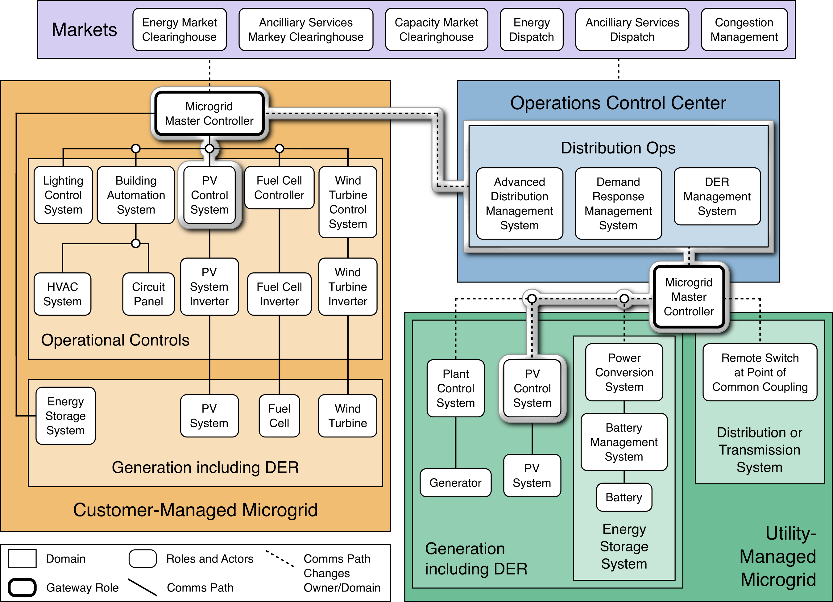
In this scenario, the Distribution Ops systems, within a utility Operations Control Center, exchange information with a Microgrid Master Control system and through this system to a PV Control System. This architecture addresses the security of these information exchanges. This architecture is not a complete cybersecurity architecture for a utility or a microgrid operator. This architecture enhances the trustworthiness of operational information exchanges between a utility and DER or microgrid operators.
This architecture helps ensure that both the DER or microgrid operator and the local utility have confidence that the information exchanges are legitimate.
4.1 Architecture Description
The project reference architecture demonstrates the following capabilities to protect, monitor, and audit DER information exchanges.
All information exchanges are by and between authenticated and authorized entities.
The networks used to exchange information are monitored, and suspicious activity is detected and reported.
A distributed ledger of information exchanges is maintained by a third party to allow both DER operators and the utility to independently verify the information exchanges.
A DER operator log collection, data analysis and visualization capability provides controlled results sharing with the utility and other DER operators.
Figure 4‑2 and Figure 4‑3 depict the reference architectures used to protect information exchanges.
Figure 4-2 Information Exchange, Monitoring, and Distributed Ledger Reference Architecture
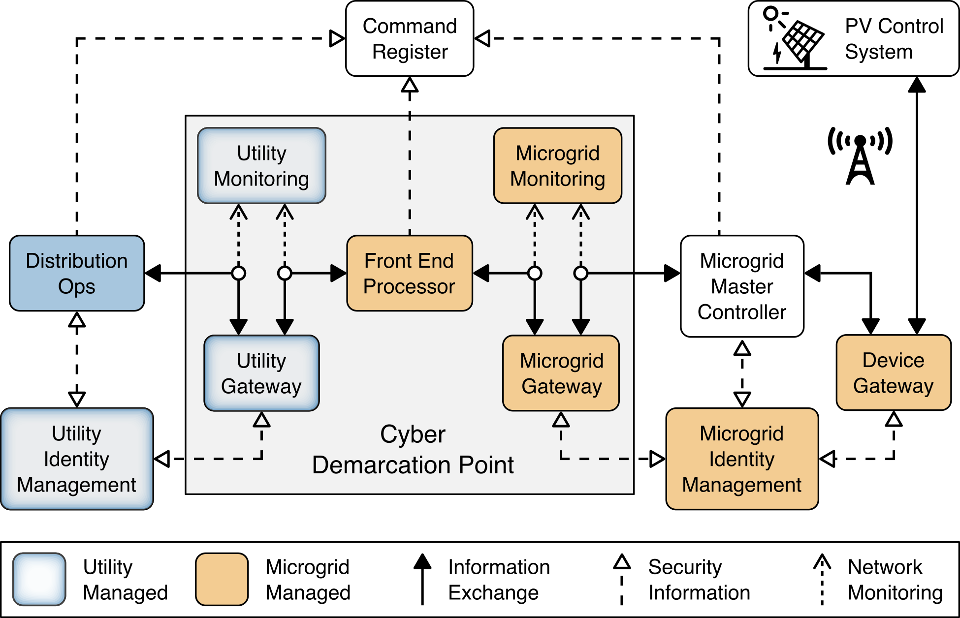
Figure 4‑2 shows the elements of the reference architecture for protecting information exchanges, monitoring network traffic, and recoding information exchanges in a distributed ledger. The core element of this architecture is the cyber demarcation point. The cyber demarcation point separates a utility network and a microgrid network that is owned and controlled by a DER operator. The cyber demarcation point is responsible for independently enforcing two distinct security policies—the utility’s security policy and the microgrid owner’s security policy. There is a cyber demarcation point at each DER operator site. It contains the following:
The utility gateway component implements the utility’s access policy. It verifies the identity of utility distribution ops systems exchanging information with the microgrid master controller and allows access based on the utility’s defined access policy. The utility gateway’s access policy uses the identity of the originating system to determine if a given information exchange is authorized. The identities and access policies are managed by the utility identity management element of the architecture. This gateway and the utility identity management element are owned, managed, and operated by the utility. We assume all information exchanges originate on the utility network via a request from the utility’s distribution ops systems to the microgrid master controller.
The front-end processor component receives information requests from the utility gateway, records them in the command register, and forwards them to the microgrid gateway.
The microgrid gateway component implements the microgrid access policy. It receives information requests from the front-end processor and passes authorized requests into the microgrid master controller. This gateway is owned, managed, and operated by the microgrid operator.
The utility cyber monitoring component examines network and application traffic on the utility network and alerts utility cybersecurity personnel if suspicious activity is detected. This component is owned, managed, and operated by the utility. This component monitors traffic to and from a DER or microgrid operator’s network.
The microgrid cyber monitoring component examines network and application traffic on the microgrid network and alerts microgrid cybersecurity personnel if suspicious activity is detected. This component is owned, managed, and operated by the microgrid operator. This component monitors traffic coming into the DER or microgrid operator’s network. It is not a complete monitoring solution for the DER or microgrid operator’s network.
In addition to the cyber demarcation point, other elements of the architecture contribute to cybersecurity.
The distribution ops systems record every information exchange they originate in the command register.
The microgrid master controller records every information exchange it receives from the microgrid gateway in the command register and forwards appropriate commands to the device gateway.
The device gateway implements a device-specific access policy. It receives requests from the microgrid master controller and passes authorized requests to the PV control system. The device gateway’s access policy uses the identity of the microgrid master controller to determine if a given information exchange is authorized. The identities and access policies are managed by the microgrid identity management element of the architecture. A device gateway allows the microgrid gateway to implement coarse-grained access policies that are not device specific. The microgrid gateway can allow a request independent of the device. The device gateways can then implement fine-grained policies that are device specific. This allows the microgrid gateway policies to be independent of the specific devices currently accessible on the microgrid network. Note that the reference architecture allows but does not require the microgrid gateway policy to be independent of the specific devices on the microgrid network. Use of the device gateway also allows micro-segmentation of the microgrid network.
This architecture allows both the utility and the microgrid operator to control access to DERs on the microgrid. Both must agree to allow access to a specific PV control system. Similarly, both the utility and the microgrid operator can detect suspicious activity. There is no requirement for the utility or the microgrid operator to use the same products to implement these capabilities. There is a potential security benefit in each organization choosing different products, which provides a degree of diversity in an implementation. The selected products, however, must be able to exchange information via defined protocols such as Sunspec Modbus.
Device gateways may connect to PV control systems via wired or wireless network segments. Figure 4‑2 shows a wireless connection.
The reference architecture assumes the DER microgrid is neither owned nor operated by the utility. The microgrid operator and the utility may each independently collect audit trails that record information exchanges. In this way, there is no single authoritative record of these exchanges. A complete audit trail would have to be constructed by combining audit records from the utility and the microgrid operator.
The distribution ops, front-end processor, and microgrid master controller in the reference architecture record information exchanges in the command register. The command register is a distributed ledger operated by a trusted third party. It provides an accurate, immutable record of all information exchanges that may be reviewed by both the utility and the DER or microgrid operators. The ledger provides an authoritative source for determining who said what to whom when and is a complete audit trail of information exchanges.
Figure 4‑3 Log Collection, Data Analysis and Visualization Reference Architecture
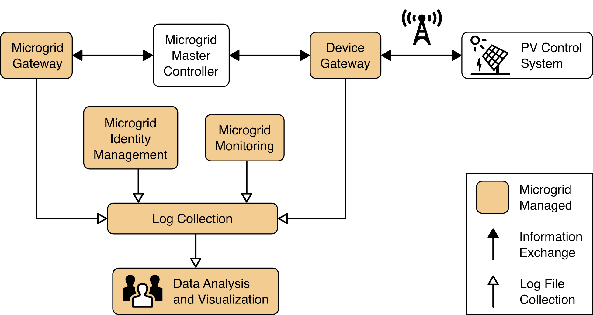
Figure 4‑3 illustrates the capabilities to collect, analyze, and visualize information from the log files generated by microgrid systems. These log files are gathered from microgrid systems by a log collector which aggregates the log data and sends it to a cloud-based analysis and visualization capability. The microgrid operator’s cyber defense analysts have full access to all the log information and analysis results. The microgrid operator may choose to share select results with the utility. It is easier to realize this selective sharing by using a cloud platform than it would be using an on-premises analysis platform. The cloud analytics platform can also enable select information sharing between and among microgrid operators.
Figure 4‑4 Privileged User Management
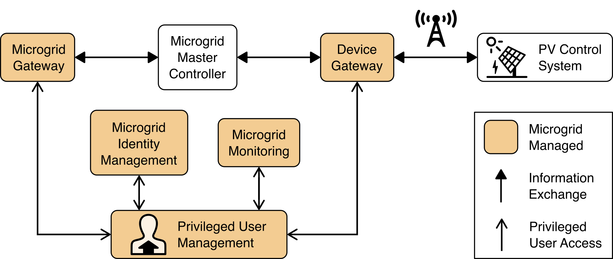
Figure 4‑4 illustrates a capability to manage the privileged users responsible for installation, configuration, operation, and maintenance of elements of the reference architecture. Privileged user management capabilities protect privileged access credentials, control access to management interfaces, and provide accountability for all privileged user actions in managing products on the microgrid.
4.2 Example Solution Description
A laboratory prototype instance of the reference architecture, called an “example solution,” was constructed to verify the design. The example solution consists of a combination of logical and physical infrastructure at the NCCoE and on the UMD campus.
The utility network and the cyber demarcation point are represented in the example solution by virtual infrastructure in the NCCoE lab.
The microgrid network is represented by three distinct components: a virtual network in the NCCoE lab, the UMD campus network, and an LTE network installed on the UMD campus. Virtual private networks (VPNs) are used to connect the NCCoE lab to the UMD campus network and to connect the UMD campus network, via an LTE network, to solar arrays on two UMD parking garages.
The distribution ops system was implemented by NCCoE-developed software that can send Sunspec Modbus commands to a PV control system and record those commands in the command register.
The utility gateway and utility identity management elements of the architecture were implemented using the Xage Security Fabric product. Identities, devices, and access policies are defined within the product and no external identity store is needed. Identities, device definitions, and access policies are managed from a central manager and distributed to edge nodes at each microgrid location for use.
The utility monitoring element of the architecture was implemented using the Radiflow iSID industrial control network monitoring product. iSID learns normal network behaviors and then detects anomalous activity.
The front-end processor (FEP) was implemented by NCCoE-developed software that receives Sunspec Modbus commands, records them in the command register, and forwards the command to the microgrid gateway.
The microgrid identity management element was implemented using the Cisco Identity Services Engine (ISE). Identities and access policies are created and managed in ISE. ISE authenticates requests to access resources on the microgrid network and, based on policy, decides if the request should be allowed. The access decisions are enforced by an ISE-enabled switch and Cisco Firepower Threat Defense next-generation firewall implementing the microgrid and device gateways.
The microgrid gateway was implemented using a Cisco Catalyst 3650 ISE-enabled network switch. The switch enforces access decision made by ISE. Connections through the switch must first authenticate to ISE. ISE makes an access decision and tells the switch to allow or deny the connection. The only connection allowed is a connection between the FEP and the Microgrid Master Controller.
The microgrid monitoring element was implemented using Cisco Cyber Vision. Cyber Vision monitors network traffic, learns normal traffic flows and behaviors, and then detects deviations from normal and other anomalies.
The Microgrid Master Controller was implemented by NCCoE-developed software that receives Sunspec Modbus commands, records them in the command register, and forwards the command to the device gateway.
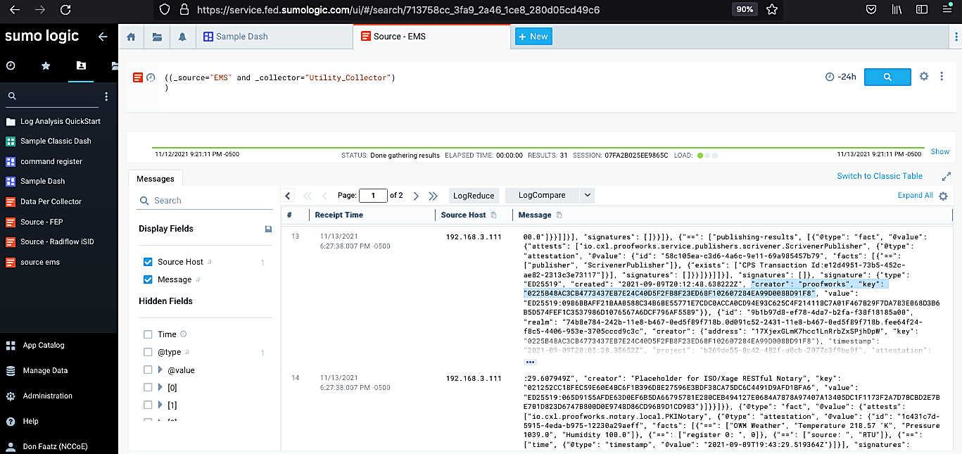
The command register was implemented using the Spherical Analytics Immutably software as a service product. Via a restful API, this product receives copies of information exchanges from the distribution ops systems, the microgrid front-end processor, and the microgrid master controller. These copies of information exchanges are enriched with configurable proofs and stored in a distributed ledger using blockchain technology. The information stored in the distributed ledger allows information exchange recipients to verify that the information received is the same as the information sent. Additionally, the command register provides a complete audit trail of information exchanges among the utility and microgrid operators. Figure 4-6 shows example records captured in the command register.
The device gateway was implemented using a Cisco Firepower Threat Defense next-generation firewall. The firewall enforces access decision made by ISE. Connections through the firewall must first authenticate to ISE. ISE makes an access decision and tells the firewall to allow or deny the connection. The only connection allowed is a connection between the Microgrid Master Controller and the PV control system.
The PV control system and associated PV array were implemented by solar array systems installed on parking garages at UMD.
Connectivity between the device gateway and PV control systems at UMD parking garages was provided by an LTE network installed by Anterix at UMD.
The log collection element was implemented with the open-source version of syslog-ng. Microgrid components that generated log data in syslog format were configured to send that data to a syslog-ng instance where it was aggregated.
The data analysis and visualization element was implemented by Sumo Logic’s software as a service cloud-based data collection, analysis, and visualization product. Figure 4‑5 shows an example visualization of analysis results. This example was produced by replaying network traffic provided by a utility over our network and observing that traffic with elements of the reference architecture. On the left side of the example, the large green and blue graph shows the amount of data provided by various collectors. Above that is a graph of login activity to systems. Below that is a graphic showing operational power faults. On the right side of the example, is a list of the top communication failure alarms and a pie chart showing what percentage of alarms are generated by each source.
The privileged user management element was implemented using TDi Technologies ConsoleWorks product. ConsoleWorks acts as a jump box that manages privileged access credentials, controls access to privileged functions and management interfaces, and captures all privileged user activity in an audit trail.
Figure 4‑5 Example of Analysis and Visualization
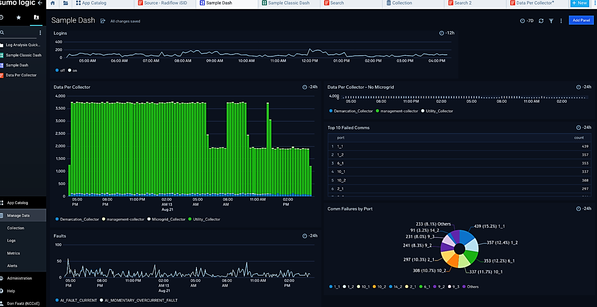
Figure 4‑6 Example Command Register Data
Details of the installation, configuration, and integration of these products into the example solution are provided in Volume C of this guide.
While the NCCoE used a suite of commercial products to address this challenge, this guide does not endorse these products, nor does it guarantee compliance with any regulatory initiatives. Neither the architecture nor the example solution addresses all cybersecurity needs for a utility or a microgrid operator. Your organization’s information security experts should identify the architecture and products that will best integrate with your existing tools and IT or operational technology (OT) system infrastructure to provide the necessary cybersecurity protection Your organization can adopt this solution or one that adheres to these guidelines in whole, or you can use this guide as a starting point for tailoring and implementing parts of a solution.
5 Security Characteristic Analysis
This section discusses the results of a security evaluation of the reference architecture shown in Figure 4‑2 and how it supports the Cybersecurity Framework Subcategories that we identified and mapped in Table 3‑1. The purpose of the security characteristic analysis is to understand the extent to which the project example solution meets its objective of demonstrating that information exchanges among DERs and electric distribution grid operations can be monitored and protected from certain cybersecurity compromises. In addition, it seeks to understand the security benefits and drawbacks of the example solution.
5.1 Assumptions and Limitations
The security characteristic analysis has the following limitations:
The analysis is not a comprehensive test of all security components nor a red-team exercise.
The analysis cannot identify all weaknesses.
The analysis does not include the lab infrastructure. We assume that the IT infrastructure used in the example solution is configured securely and properly managed. Testing this infrastructure would reveal only weaknesses in implementation that would not be relevant to those adopting this reference architecture.
The analysis considers only those product capabilities explicitly used in the example solution. Products may have additional capabilities that are not considered.
The products used to implement the utility, microgrid, and DER gateways use identity to grant or allow access. The gateways are not firewalls and do not provide network protocol-level access control.
While identities are used to control access, identity and access management technologies and processes are not addressed in the reference architecture or the example solution. See NIST SP 1800-2, Identity and Access Management for Electric Utilities, for more information.
The example solution includes a limited privileged user management capability. NIST SP 1800-18, Privileged Account Management for the Financial Services Sector, provides additional guidance on managing privileged user access.
5.2 Build Testing
Testing verifies that the products we integrated in the lab environment work together as intended by the reference architecture. For this project, we designed six test scenarios that are defined in Table 5‑1 through Table 5‑6. These test scenarios are presented in terms of the reference architecture element and are independent of the specific products used to implement the example solution.
5.2.1 Test Scenario 1: Communication Between the Utility and a DER Is Secure
This test case verifies that authenticated and authorized systems on the utility network can communicate with a DER connected to the microgrid network.
Table 5‑1 Test Procedures: Communication Between the Utility and a DER Is Secure
Procedure |
|
Architectural Requirements |
|
Capabilities/ Requirements |
|
Expected Results |
|
Actual Results |
|
Overall Results |
|
5.2.2 Test Scenario 2: Integrity of Command Register Data and Communication Is Verified
This test case verifies data providence and integrity across the system for commands being exchanged between the utility and the PV control system.
Table 5‑2 Test Procedure: Integrity of Command Register Data and Communication Is Verified
Procedure |
|
Architectural Requirements |
|
Capabilities/ Requirements |
|
Expected Results |
|
Actual Results |
|
Overall Results |
|
5.2.3 Test Scenario 3: Log File Information Can Be Captured and Analyzed
This test case verifies the capabilities of capturing and analyzing log data within the microgrid network.
Table 5‑3 Test Procedure: Log File Information Can Be Captured and Analyzed
Procedure |
|
Architectural Requirements |
|
Capabilities/ Requirements |
|
Expected Results |
|
Actual Results |
|
Overall Results |
|
5.2.5 Test Scenario 5: Malicious Activity Is Detected
This test case verifies the system’s ability to detect anomalous or malicious behavior on the network.
Table 5‑5 Test Procedure: Malicious Activity Is Detected
Procedure |
|
Architectural Requirements |
|
Capabilities Requirements |
|
Expected Results |
|
Actual Results |
|
Overall Result |
|
5.2.6 Test Scenario 6: Privileged User Access Is Managed
This test case verifies that privileged users are authenticated and authorized to access only those devices to which they have been given proper privileges.
Table 5‑6 Test Procedure: Privileged User Access Is Managed
Procedure |
|
Architectural Requirements |
|
Capabilities Requirements |
|
Expected Results |
|
Actual Results |
|
Overall Results |
|
5.3 Scenarios and Findings
Security evaluation of the reference architecture involves assessing how well the architecture addresses the security characteristics that it is intended to support. The Cybersecurity Framework Subcategories were used to provide structure to the security assessment. Using the Cybersecurity Framework Subcategories as a basis for organizing the analysis allows systematic consideration of the reference architecture’s support for the intended security characteristics.
In the project description, we described a sequence of events that could lead to a malicious entity being able to masquerade as either a utility operator or a microgrid operator. If that were to occur, the utility could not trust the information that it would receive from the microgrid operators. Likewise, the microgrid operators could not trust the utility’s information exchange.
This section analyzes the example solution in terms of the Cybersecurity Frameworkʼs specific Subcategories supported, creating trust in information exchanges between the utility and the microgrid operation.
5.3.1 Identity Management, Authentication, and Access Control
5.3.1.1 PR.AC-1: Identities and Credentials Are Issued, Managed, Verified, Revoked, and Audited for Authorized Devices, Users, and Processes
This Cybersecurity Framework Subcategory is supported in the reference architecture by the utility identity management, microgrid identity management, and privileged user management elements of the architecture. The utility can establish identities and credentials using the utility identity management element. These identities and credentials are used by the utility gateway. The microgrid operator can establish identities, credentials, and access policies using the microgrid identity management element. These identities and access rules are used by the microgrid gateway and by the device gateway.
The privileged user management element manages the privileged access credentials used to access the management interfaces of architecture elements in the microgrid environment.
5.3.1.2 PR.AC-3: Remote Access Is Managed
This Cybersecurity Framework Subcategory is supported by the reference architecture’s cyber demarcation point. The cyber demarcation point uses identity to control access by the utility to devices on the microgrid network. The reference architecture has two separate policy domains: the utility domain and the microgrid operator domain. The cyber demarcation point consists of a utility gateway and a microgrid gateway. The utility controls the identities used and the access policy enforced by the utility gateway. The microgrid operator controls the identities used and the access policy enforced by the microgrid gateway. These two gateways control remote access by the utility to devices on the microgrid network.
5.3.1.3 PR.AC-4: Access Permissions and Authorizations Are Managed, Incorporating the Principles of Least Privilege and Separation of Duties
This Cybersecurity Framework Subcategory is supported by the reference architecture’s cyber demarcation point and the privileged user management capability. The cyber demarcation point uses identity to control access by the utility to devices on the microgrid network. The reference architecture has two separate policy domains: the utility domain and the microgrid operator domain. The cyber demarcation point consists of a utility gateway and a microgrid gateway. The utility controls the access policy enforced by the utility gateway. The microgrid operator controls the access policy enforced by the microgrid gateway. These two gateways control remote access by the utility to devices on the microgrid network.
The privileged user management capability controls access to the management interfaces of the systems and services on the microgrid network. Policy in the privileged user management capability determines who has access to perform privileged functions and defines required separation of duties to mitigate the risk of a malicious privileged user. The privileged user management capability enforces these policies for all access to management interfaces.
5.3.1.4 PR.AC-5: Network Integrity Is Protected (e.g., Network Segregation, Network Segmentation)
This Cybersecurity Framework Subcategory is supported by the reference architecture’s cyber demarcation point and by network segmentation within the microgrid.
The utility is not exchanging information directly with the microgrid, but it is exchanging information through the cyber demarcation point. The reference architecture provides gateways to represent the microgrid and utility independently. Thus, the utility would manage communications and security interactions through its gateway; the microgrid operator would also manage its gateway and the assets on its side. The device gateways within the microgrid network enable fine-grained segmentation of resources on that network.
5.3.2 Data Security
5.3.2.1 PR.DS-1: Data at Rest Is Protected
This Cybersecurity Framework Subcategory is supported by the reference architecture’s command register capability. The command register provides protection at rest for the audit trail of information exchanges between the utility and microgrid operator. The ledger ensures the integrity of the audit trail records. The distributed nature of the ledger ensures availability of the audit trail records.
5.3.2.2 PR.DS-2: Data in Transit Is Protected
This Cybersecurity Framework Subcategory is supported using VPNs to encrypt traffic between the NCCoE lab, the UMD campus network, and the solar arrays located on parking garages at UMD. In addition to the VPN, the data is further protected in transit between the UMD campus network and the DERs (solar arrays) by security measures built into LTE (Long Term Evolution), the wireless network standard implemented in the reference architecture.
5.3.2.3 PR.DS-6: Integrity-Checking Mechanisms Are Used to Verify Software, Firmware, and Information Integrity
This Cybersecurity Framework Subcategory is supported by the reference architecture’s command register.
The command register provides an immutable, fully distributed audit trail accessible by all parties involved in information exchanges. Using the command register, the full sequence of events between the utility and DER operators is observable by all parties. Information exchange recipients can use the command register to verify that the information they received is the same information sent that was sent.
5.3.3 Anomalies and Events
5.3.3.1 DE.AE-1: A Baseline of Network Operations and Expected Data Flows for Users and Systems Is Established and Managed
This Cybersecurity Framework Subcategory is supported by the utility cyber monitoring and microgrid cyber monitoring components of the cyber demarcation point in the reference architecture. The cyber monitoring components are self-training. They monitor network traffic and observe the normal behavior and flow of information into and out of the cyber demarcation.
5.3.3.2 DE.AE-2: Detected Events Are Analyzed to Understand Attack Targets and Methods
This Cybersecurity Framework Subcategory is supported by the utility cyber monitoring and microgrid cyber monitoring components of the cyber demarcation point and data analysis and visualization in the reference architecture. They monitor network traffic and observe the normal behavior and flow of information into and out of the cyber demarcation.
The data analysis and visualization element of the architecture analyzes log data from services on the microgrid network to identify suspicious behavior and to alert analysts. Log data is compared with the expected normal behavioral characteristics that are learned over time. Deviations from the expected normal behavior are reported as events.
5.3.3.4 DE.AE-5: Incident Alert Thresholds Are Established
This Cybersecurity Framework Subcategory is supported by the utility cyber monitoring and microgrid cyber monitoring components of the cyber demarcation point as well as by the data analysis and visualization capability. Each of these monitoring and analysis capabilities has established thresholds for detecting anomalies and generating alerts.
5.3.4 Security Continuous Monitoring
5.3.4.1 The Information System and Assets Are Monitored to Identify Cybersecurity Events and Verify the Effectiveness of Protective Measures
This Cybersecurity Framework Subcategory is supported by the utility cyber monitoring and microgrid cyber monitoring components of the cyber demarcation point, and by the log analysis capability. Each of these monitors aspects of the system and identifies cybersecurity events.
5.3.4.2 DE.CM-2: The Physical Environment Is Monitored to Detect Potential Cybersecurity Events
This Cybersecurity Framework Subcategory is supported by the physical security systems at the NCCoE and UMD. Both the NCCoE and UMD have physical access control systems in place to control and monitor access to the physical locations where the example solution components are installed. NIST monitors the NCCoE physical access control system. UMD monitors its physical security system.
5.3.4.3 DE.CM-4: Malicious Code Is Detected
This Cybersecurity Framework Subcategory is supported by the utility cyber monitoring and microgrid cyber monitoring components of the cyber demarcation point. These components can detect some malicious code types based on analysis of monitored network traffic.
5.3.4.4 DE.CM-7: Monitoring for Unauthorized Personnel, Connections, Devices, and Software Is Performed
This Cybersecurity Framework Subcategory is supported by the microgrid cyber monitoring component of the cyber demarcation point in the reference architecture.
The microgrid cyber monitoring component develops a model of the expected devices and information flows. Unexpected devices or connections are detected and reported.
6 Future Build Considerations
The NCCoE recognizes that the reference architecture and example solution described in this practice guide demonstrate some of the tenets and principles of a zero trust architecture as defined in NIST SP 800-207, Zero Trust Architecture. While most discussions related to zero trust architectures focus on implementations for IT business networks and use cases, future NCCoE Energy Sector projects might consider implementing a zero trust architecture in an ICS environment. For example, we might consider extending this architecture and example solution to include dynamic access control for DERs or other grid-edge devices connecting to the distribution grid.