NIST SPECIAL PUBLICATION 1800-32C
Securing Distributed Energy Resources:
An Example of Industrial Internet of Things Cybersecurity
Volume C:
How-to Guides
Jim McCarthy
National Cybersecurity Center of Excellence
National Institute of Standards and Technology
Don Faatz
Nik Urlaub
John Wiltberger
Tsion Yimer
The MITRE Corporation
McLean, Virginia
February 2022
FINAL
This publication is available free of charge from https://doi.org/10.6028/NIST.SP.1800-32

DISCLAIMER
Certain commercial entities, equipment, products, or materials may be identified by name or company logo or other insignia in order to acknowledge their participation in this collaboration or to describe an experimental procedure or concept adequately. Such identification is not intended to imply special status or relationship with NIST or recommendation or endorsement by NIST or NCCoE; neither is it intended to imply that the entities, equipment, products, or materials are necessarily the best available for the purpose.
While NIST and the NCCoE address goals of improving management of cybersecurity and privacy risk through outreach and application of standards and best practices, it is the stakeholder’s responsibility to fully perform a risk assessment to include the current threat, vulnerabilities, likelihood of a compromise, and the impact should the threat be realized before adopting cybersecurity measures such as this recommendation.
National Institute of Standards and Technology Special Publication 1800-32C, Natl. Inst. Stand. Technol. Spec. Publ. 1800-32C, 68 pages, (February 2022), CODEN: NSPUE2
FEEDBACK
As a private-public partnership, we are always seeking feedback on our practice guides. We are particularly interested in seeing how businesses apply NCCoE reference designs in the real world. If you have implemented the reference design, or have questions about applying it in your environment, please email us at energy_nccoe@nist.gov.
All comments are subject to release under the Freedom of Information Act.
NATIONAL CYBERSECURITY CENTER OF EXCELLENCE
The National Cybersecurity Center of Excellence (NCCoE), a part of the National Institute of Standards and Technology (NIST), is a collaborative hub where industry organizations, government agencies, and academic institutions work together to address businesses’ most pressing cybersecurity issues. This public-private partnership enables the creation of practical cybersecurity solutions for specific industries, as well as for broad, cross-sector technology challenges. Through consortia under Cooperative Research and Development Agreements (CRADAs), including technology partners—from Fortune 50 market leaders to smaller companies specializing in information and operational technology (OT) security—the NCCoE applies standards and best practices to develop modular, adaptable example cybersecurity solutions using commercially available technology. The NCCoE documents these example solutions in the NIST Special Publication 1800 series, which maps capabilities to the NIST Cybersecurity Framework and details the steps needed for another entity to re-create the example solution. The NCCoE was established in 2012 by NIST in partnership with the State of Maryland and Montgomery County, Maryland.
NIST CYBERSECURITY PRACTICE GUIDES
NIST Cybersecurity Practice Guides (Special Publication 1800 series) target specific cybersecurity challenges in the public and private sectors. They are practical, user-friendly guides that facilitate adoption of standards-based approaches to cybersecurity. They show members of the information security community how to implement example solutions that help them align with relevant standards and best practices, and provide users with the materials lists, configuration files, and other information they need to implement a similar approach.
The documents in this series describe example implementations of cybersecurity practices that businesses and other organizations may voluntarily adopt. These documents do not describe regulations or mandatory practices, nor do they carry statutory authority.
ABSTRACT
The Industrial Internet of Things (IIoT) refers to the application of instrumentation and connected sensors and other devices to machinery and vehicles in the transport, energy, and other critical infrastructure sectors. In the energy sector, distributed energy resources (DERs) such as solar photovoltaics including sensors, data transfer and communications systems, instruments, and other commercially available devices that are networked together. DERs introduce information exchanges between a utility’s distribution control system and the DERs to manage the flow of energy in the distribution grid.
This practice guide explores how information exchanges among commercial- and utility-scale DERs and electric distribution grid operations can be monitored and protected from certain cybersecurity threats and vulnerabilities.
The NCCoE built a reference architecture using commercially available products to show organizations how several cybersecurity capabilities, including communications and data integrity, malware detection, network monitoring, authentication and access control, and cloud-based analysis and visualization can be applied to protect distributed end points and reduce the IIoT attack surface for DERs.
KEYWORDS
data integrity; distributed energy resource; industrial internet of things; malware; microgrid; smart grid
ACKNOWLEDGMENTS
We are grateful to the following individuals for their generous contributions of expertise and time.
Name |
Organization |
|---|---|
Mike Brozek |
Anterix |
Mark Poulin |
Anterix |
Moin Shaikh |
Bedrock Systems |
John Walsh |
Bedrock Systems |
Michael Harttree |
Cisco |
Matthew Hyatt |
Cisco |
Peter Romness |
Cisco |
Shanna Ramirez |
CPS Energy |
Pete Tseronis |
Dots and Bridges |
TJ Roe |
Radiflow |
Gavin Nicol |
Spherical Analytics |
Chris Rezendes |
Spherical Analytics |
Jon Rezendes |
Spherical Analytics |
Scott Miller |
Sumo Logic |
Doug Natal |
Sumo Logic |
Rusty Hale |
TDi Technologies |
Bill Johnson |
TDi Technologies |
Samantha Pelletier |
TDi Technologies |
Don Hill |
University of Maryland |
Kip Gering |
Xage Security |
Justin Stunich |
Xage Security |
Andy Sugiarto |
Xage Security |
The Technology Partners/Collaborators who participated in this build submitted their capabilities in response to a notice in the Federal Register. Respondents with relevant capabilities or product components were invited to sign a Cooperative Research and Development Agreement (CRADA) with NIST, allowing them to participate in a consortium to build this example solution. We worked with:
Technology Partner/Collaborator |
Product |
|---|---|
LTE infrastructure and communications |
|
Cisco Identity Services Engine; Cisco Cyber Vision; Cisco Firepower Threat Defense |
|
subject matter expertise |
|
iSID Industrial Threat Detection |
|
Immutably™, Proofworks™, and Scrivener™ |
|
Sumo Logic Enterprise |
|
ConsoleWorks |
|
campus DER microgrid infrastructure |
|
Xage Security Fabric |
DOCUMENT CONVENTIONS
The terms “shall” and “shall not” indicate requirements to be followed strictly to conform to the publication and from which no deviation is permitted. The terms “should” and “should not” indicate that among several possibilities, one is recommended as particularly suitable without mentioning or excluding others, or that a certain course of action is preferred but not necessarily required, or that (in the negative form) a certain possibility or course of action is discouraged but not prohibited. The terms “may” and “need not” indicate a course of action permissible within the limits of the publication. The terms “can” and “cannot” indicate a possibility and capability, whether material, physical, or causal.
PATENT DISCLOSURE NOTICE
NOTICE: The Information Technology Laboratory (ITL) has requested that holders of patent claims whose use may be required for compliance with the guidance or requirements of this publication disclose such patent claims to ITL. However, holders of patents are not obligated to respond to ITL calls for patents and ITL has not undertaken a patent search in order to identify which, if any, patents may apply to this publication.
As of the date of publication and following call(s) for the identification of patent claims whose use may be required for compliance with the guidance or requirements of this publication, no such patent claims have been identified to ITL.
No representation is made or implied by ITL that licenses are not required to avoid patent infringement in the use of this publication.
List of Figures
Figure 1‑1 Information Exchange, Monitoring, and Command Register
Figure 1‑2 Log Collection, Data Analysis, and Visualization
Figure 1‑3 Privileged User Management
Figure 1‑4 Overview of Laboratory Infrastructure
Figure 1‑5 Project Virtual Networks
Figure 1‑6 Project Infrastructure at UMD
Figure 1‑7 Commercial Products Integrated into Example Solution
Figure 2‑1 Anterix Cellular Network Implementation
Figure 2‑2 Cisco Cyber Vision in the Example Solution
Figure 2‑3 Cisco ISE Position in the Example Solution
Figure 2‑4 Radiflow iSID position in the example solution
Figure 2‑5 Sumo Logic Role in the Example Solution
Figure 2‑6 Sumo Logic Location in the Example Solution
Figure 2‑7 ConsoleWorks Position in the Example Solution
Figure 2‑8 Xage Implementation of Reference Architecture Elements
Figure 2‑9 Xage Location in the Example Solution
Figure 2‑10 syslog-ng Location in the Example Solution
1 Introduction
This volume of the guide shows information technology (IT) professionals and security engineers how we implemented the example solution. We cover all of the products employed in this reference design. We do not re-create the product manufacturers’ documentation, which is presumed to be widely available. Rather, these volumes show how we incorporated the products together in our environment.
Note: These are not comprehensive tutorials. There are many possible service and security configurations for these products that are out of scope for this reference design. The instructions provided herein include default credentials for product installation. These credentials should be changed following successful installation.
1.1 How to Use this Guide
This National Institute of Standards and Technology (NIST) Cybersecurity Practice Guide demonstrates a standards-based reference architecture and provides users with the information they need to use this architecture to ensure trustworthy information exchange between a utility’s distribution operations systems and a microgrid control system. This reference architecture is modular and can be deployed in whole or in part.
This guide contains three volumes:
NIST Special Publication (SP) 1800-32A: Executive Summary
NIST SP 1800-32B: Approach, Architecture, and Security Characteristics – what we built and why
NIST SP 1800-32C: How-To Guides – instructions for building the example solution (you are here)
Depending on your role in your organization, you might use this guide in different ways:
Business decision makers, including chief security and technology officers, will be interested in the Executive Summary, NIST SP 1800-32A, which describes the following topics:
challenges utilities and microgrid operators can face in securely exchanging control and status information
example solution built at the National Cybersecurity Center of Excellence (NCCoE)
benefits of adopting the example solution
Technology or security program managers who are concerned with how to identify, understand, assess, and mitigate risk will be interested in NIST SP 1800-32B, which describes what we did and why. The following sections will be of particular interest:
Section 3.4, Risk Assessment, describes the risk analysis we performed.
Section 3.4.4, Security Control Map and Technologies, maps the security characteristics of this reference architecture to cybersecurity standards and best practices.
You might share the Executive Summary, NIST SP 1800-32A, with your leadership team members to help them understand the importance of adopting standards-based approaches to trustworthy information exchanges between distribution operations (distribution ops) and microgrid control systems.
IT and operational technology (OT) professionals who want to implement an approach like this will find this whole practice guide useful. You can use this How-To portion of the guide, NIST SP 1800-32C, to replicate all or parts of the example solution created in our lab. This How-To portion of the guide provides specific product installation, configuration, and integration instructions for implementing the example solution. We do not recreate the product manufacturers’ documentation, which is generally widely available. Rather, we show how we incorporated the products together in our environment to create an example solution.
This guide assumes that IT and OT professionals have experience implementing security products within the enterprise. While we have used a suite of commercial products to address this challenge, this guide does not endorse these particular products. Your organization can adopt this solution or one that adheres to these guidelines in whole, or you can use this guide as a starting point for tailoring and implementing parts of the example solution to provide trustworthy information exchanges. Your organization’s security experts should identify the products that will best integrate with your existing tools and OT infrastructure. We hope that you will seek products that are congruent with applicable standards and best practices. Section 2, Product Installation Guides, lists the products that we used and explain how they are used in the example solution to implement the reference architecture.
A NIST Cybersecurity Practice Guide does not describe “the” solution, but a possible solution. This is a draft guide. We seek feedback on its contents and welcome your input. Comments, suggestions, and success stories will improve subsequent versions of this guide. Please contribute your thoughts to energy_nccoe@nist.gov.
1.2 Typographic Conventions
The following table presents typographic conventions used in this volume.
Typeface/ Symbol |
Meaning |
Example |
|---|---|---|
Italics |
file names and path names; references to documents that are not hyperlinks; new terms; and placeholders |
For language use and style guidance, see the NCCoE Style Guide. |
Bold |
names of menus, options, command buttons, and fields |
Choose File > Edit. |
Monospace |
command-line input, onscreen computer output, sample code examples, and status codes |
|
Monospace (block) |
multi-line input, on-screen computer output, sample code examples, status codes |
% mkdir -v nccoe_projects
mkdir: created directory 'nccoe_projects'
|
blue text |
link to other parts of the document, a web URL, or an email address |
All publications from NIST’s NCCoE are available at https://www.nccoe.nist.gov. |
1.3 Reference Architecture Summary
The reference architecture has three parts:
information exchange, monitoring, and command register (Figure 1-1)
log collection, data analysis and visualization (Figure 1-2)
privileged user management (Figure 1-3)
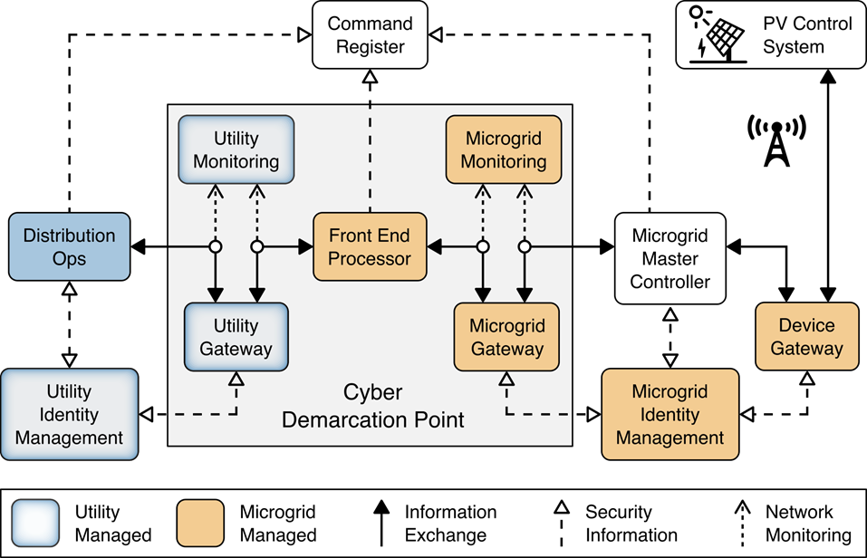
The information exchange, monitoring, and command register portion of the reference architecture provides those gateway (GW) elements that ensure only authorized entities can exchange information, monitoring elements that detect anomalous and potentially malicious activities, and a command register that captures a complete record of all information exchanges. This portion of the reference architecture consists of:
The utility GW component implements the utility’s access policy.
The front-end processor component receives information requests from the utility GW, records them in the command register, and forwards them to the microgrid GW.
The microgrid GW component implements the microgrid access policy.
The utility cyber monitoring component examines network and application traffic on the utility network and alerts utility cybersecurity personnel if anomalous activity is detected.
The microgrid cyber monitoring component examines network and application traffic on the microgrid network and alerts microgrid cybersecurity personnel if anomalous activity is detected.
The distribution ops systems record every information exchange they originate in the command register.
The microgrid master controller records every information exchange it receives from the microgrid GW in the command register and forwards appropriate commands to the device GW.
The device GW implements a device-specific access policy.
* The command register records all information exchanges in a distributed ledger.
The photovoltaic (PV) control system controls the PV DER.
Figure 1‑1 Information Exchange, Monitoring, and Command Register
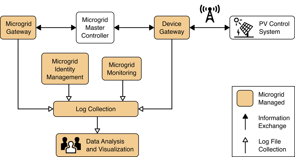
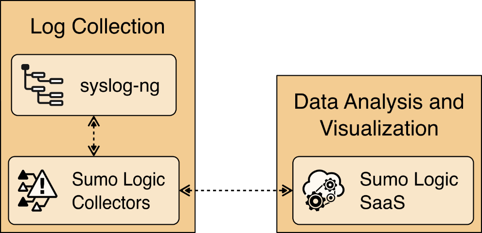
The log collection, data analysis and visualization portion of the reference architecture provides security information and event management capabilities for the microgrid operator and the ability to selectively share security-relevant information with the utility platform. The microgrid GW, microgrid monitoring device GW, and microgrid identity management elements of the reference architecture report event information to a log collection element. The log collection element forwards event information to an analysis and visualization capability that detects anomalies and reports them to microgrid operations personnel.
Figure 1‑2 Log Collection, Data Analysis, and Visualization
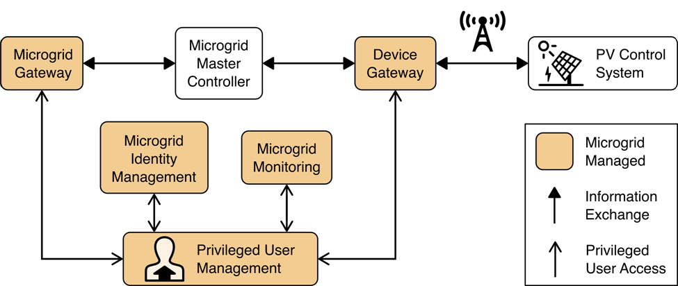
The privileged user management portion of the reference architecture provides capabilities to manage the privileged users responsible for installation, configuration, operation, and maintenance of elements of the reference architecture. Privileged user management capabilities protect privileged access credentials, control access to management interfaces, and provide accountability for all privileged user actions in managing products on the microgrid.
Figure 1‑3 Privileged User Management
1.4 Laboratory Infrastructure
We constructed a laboratory prototype of the reference architecture, called the “example solution,” to verify the design. The example solution is described in Section 1.5. The example solution consists of a combination of logical and physical infrastructure at the NCCoE and on the University of Maryland (UMD) campus. This section describes that laboratory infrastructure. Figure 1‑4 presents a high-level overview of the project’s lab infrastructure.
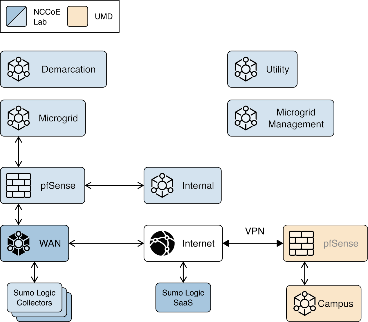
Figure 1‑4 Overview of Laboratory Infrastructure
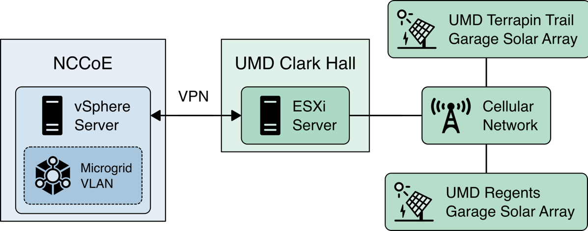
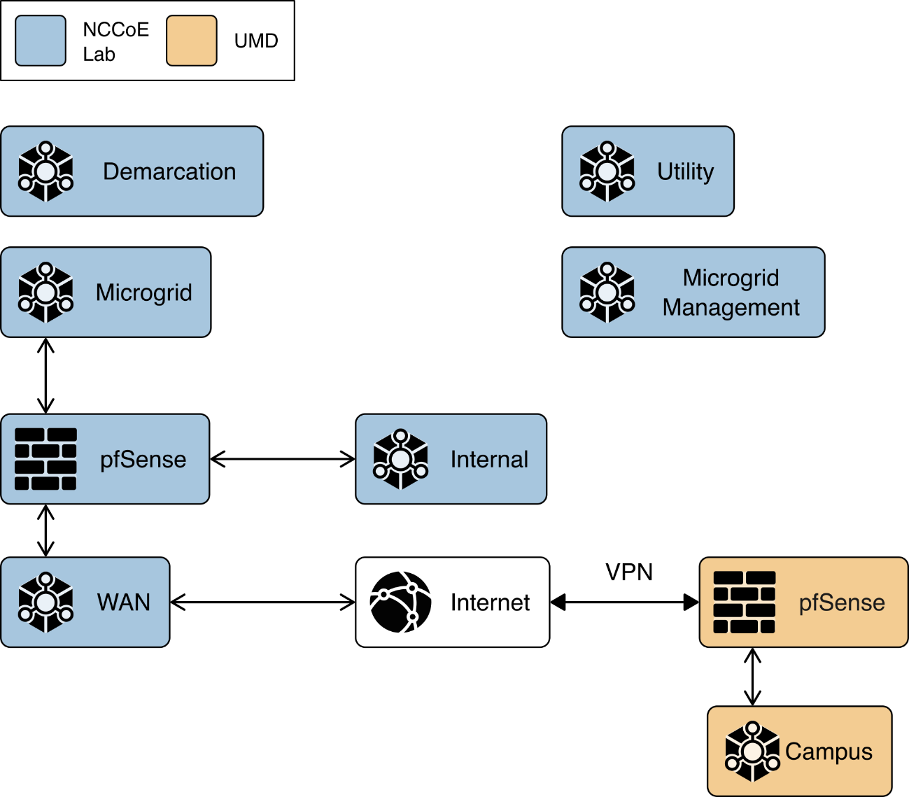
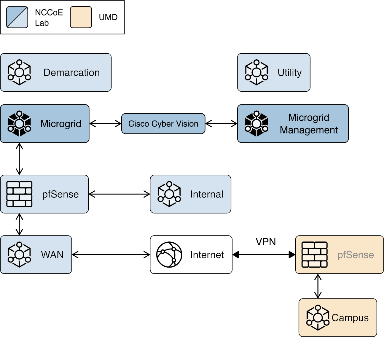
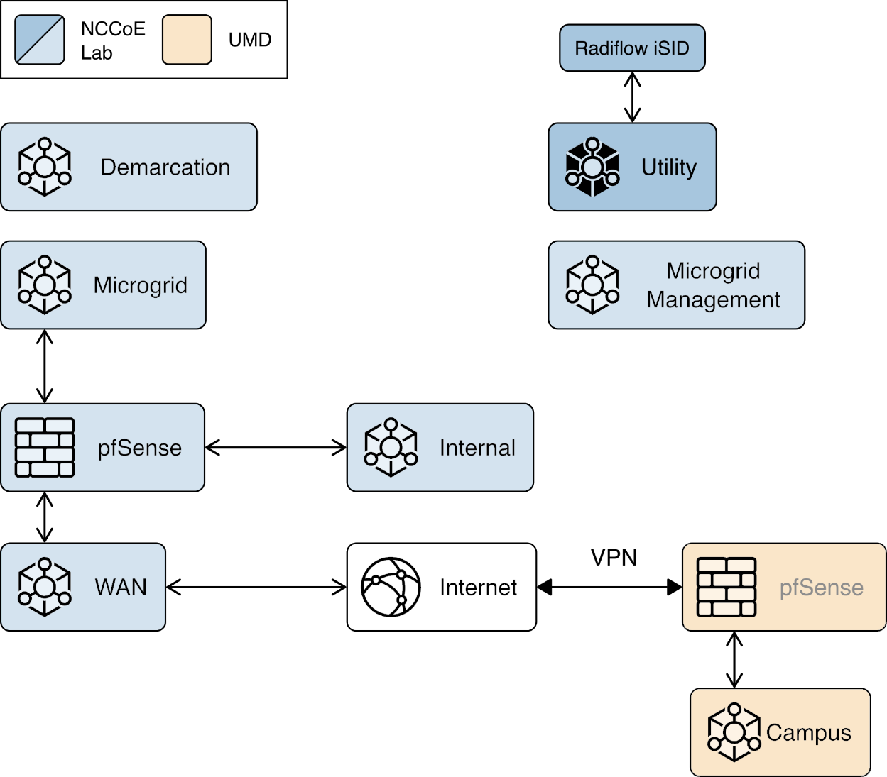
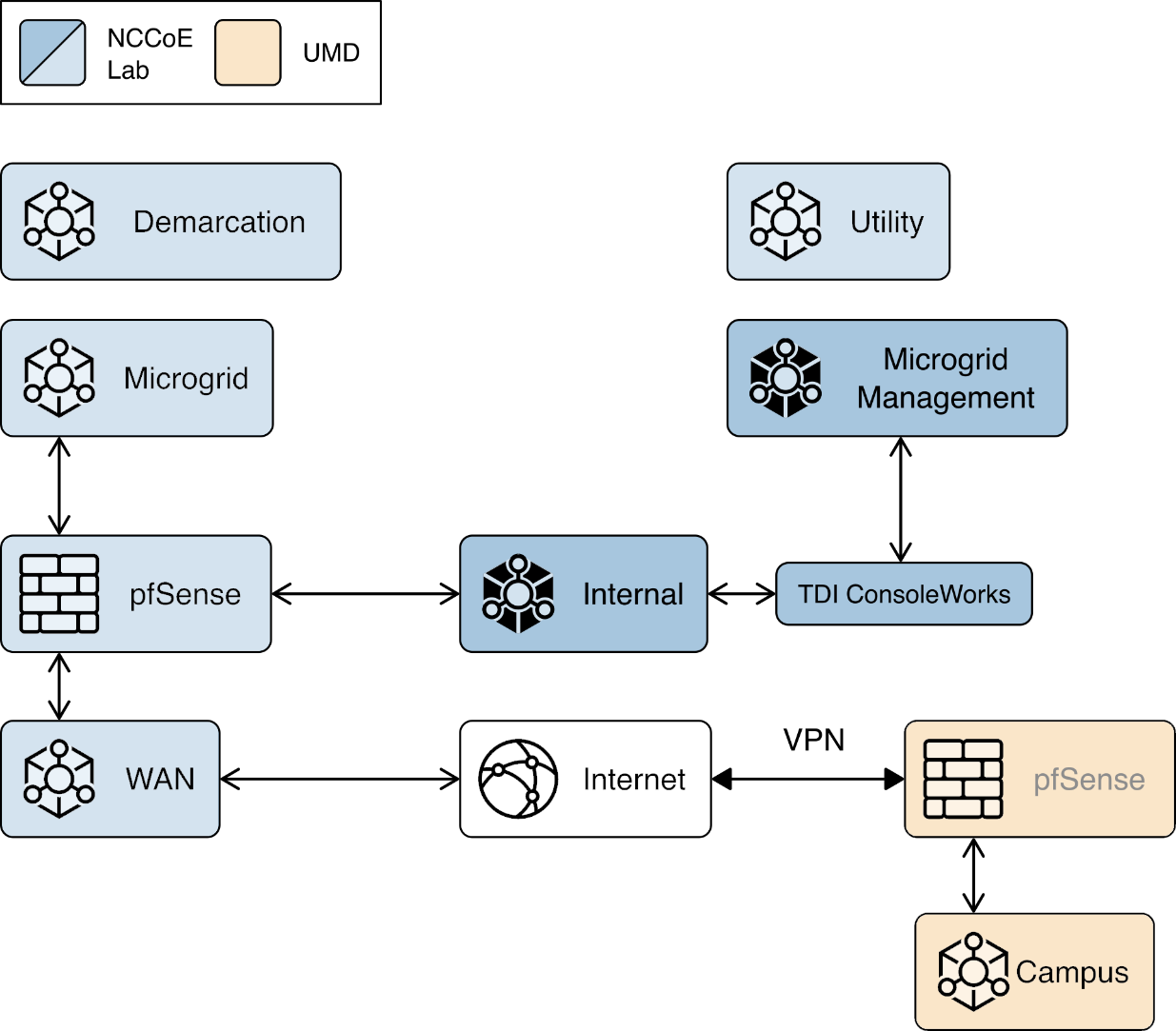
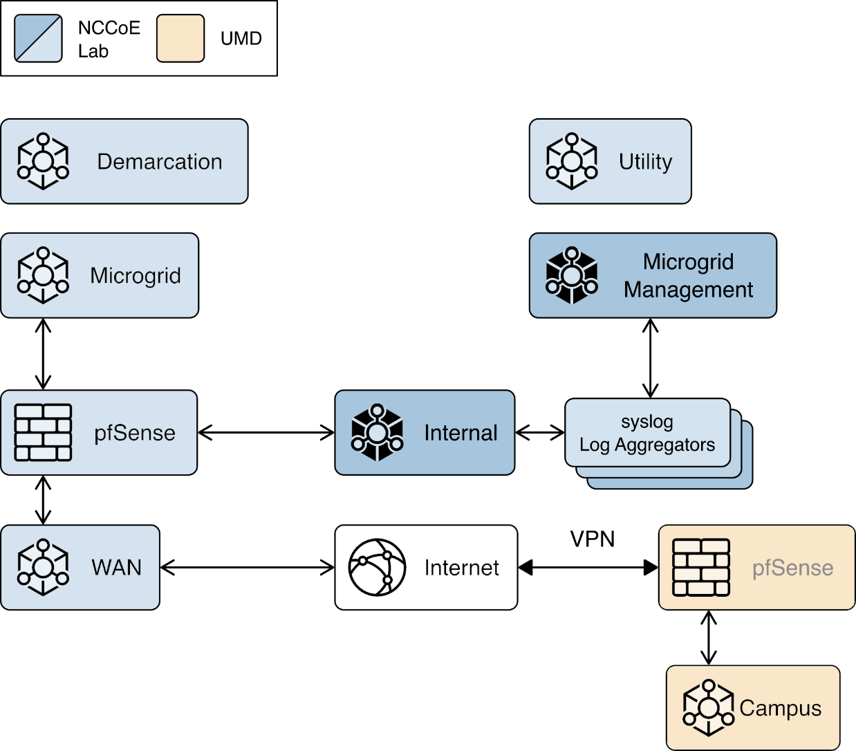
The core of our laboratory infrastructure is a virtual lab located at NCCoE and created in VMware vSphere 6.7. Within vSphere we defined six virtual networks. Each of these virtual networks represents a real-world network that would be part of a deployed instance of the reference architecture. Figure 1‑5 illustrates these virtual networks.
The Utility virtual network represents the network a distribution utility uses to manage equipment related to power flow on its distribution grid.
The Demarcation virtual network represents a network in each cyber demarcation point that provides the controlled interface between a utility’s network and a DER or microgrid operator’s network.
The Microgrid virtual network represents the network a DER or microgrid operator uses to manage power generation and storage resources.
The Microgrid Management virtual network represents a dedicated network for managing the cyber systems used on the Microgrid network.
The Internal virtual network represents networks used by a DER or microgrid operator for activities other than managing power generation and storage resources such as general business functions.
The WAN virtual network is a lab network that provides access from the virtual lab to the Internet.
A Virtual Private Network (VPN) connects the vSphere environment at NCCoE to UMD.
The reference architecture and the example solution provide an approach to ensuring information exchanges between a utility and a DER or microgrid operator are trustworthy. Neither the reference architecture nor the example solution provides a complete cybersecurity solution for utility networks, DER and microgrid operator networks, or interfacing of these networks to the Internet. Use of the reference architecture or example solution does not guarantee compliance with any regulatory initiatives.
Figure 1‑5 Project Virtual Networks
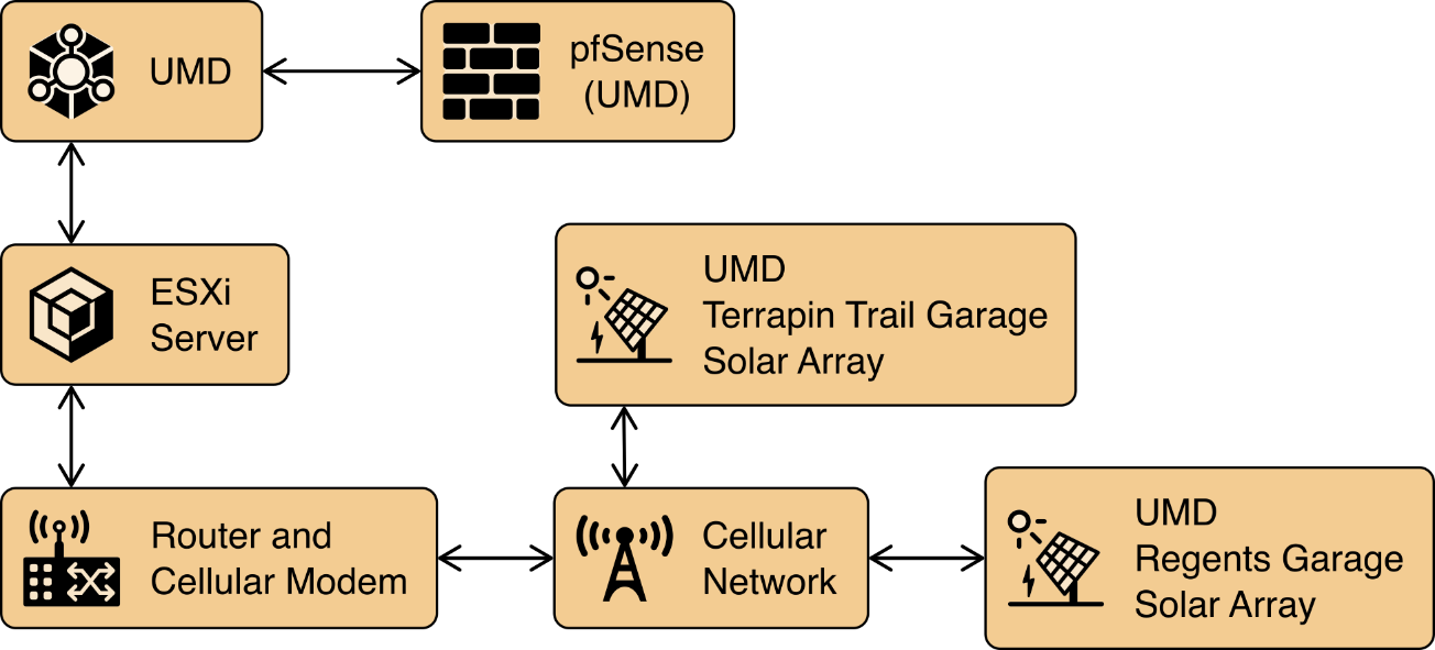
In addition to the core laboratory infrastructure, additional virtual and physical infrastructure is located at UMD’s Clark Hall, Terrapin Trail parking garage, and Regents parking garage.
A vmWare ESXI server is located in Clark Hall and connected to the UMD campus network. This server allows us to deploy software to UMD. A cellular network provides connectivity from the ESXI server to solar arrays on the Terrapin Trail and Regents parking garages.
Figure 1‑6 illustrates the extended infrastructure at UMD.
Figure 1‑6 Project Infrastructure at UMD
1.5 Example Solution Overview
Figure 1‑7 shows how different products are integrated to create the example solution.
The utility network and the cyber demarcation point of the reference architecture are represented in the example solution by virtual infrastructure in the NCCoE lab. The microgrid network is represented in the example solution by a virtual network in the NCCoE lab, the UMD campus network, and a Long Term Evolution (LTE network) installed on the UMD campus.
The components of the reference architecture’s cyber demarcation are implemented using these products.
Figure 1‑7 Commercial Products Integrated into Example Solution
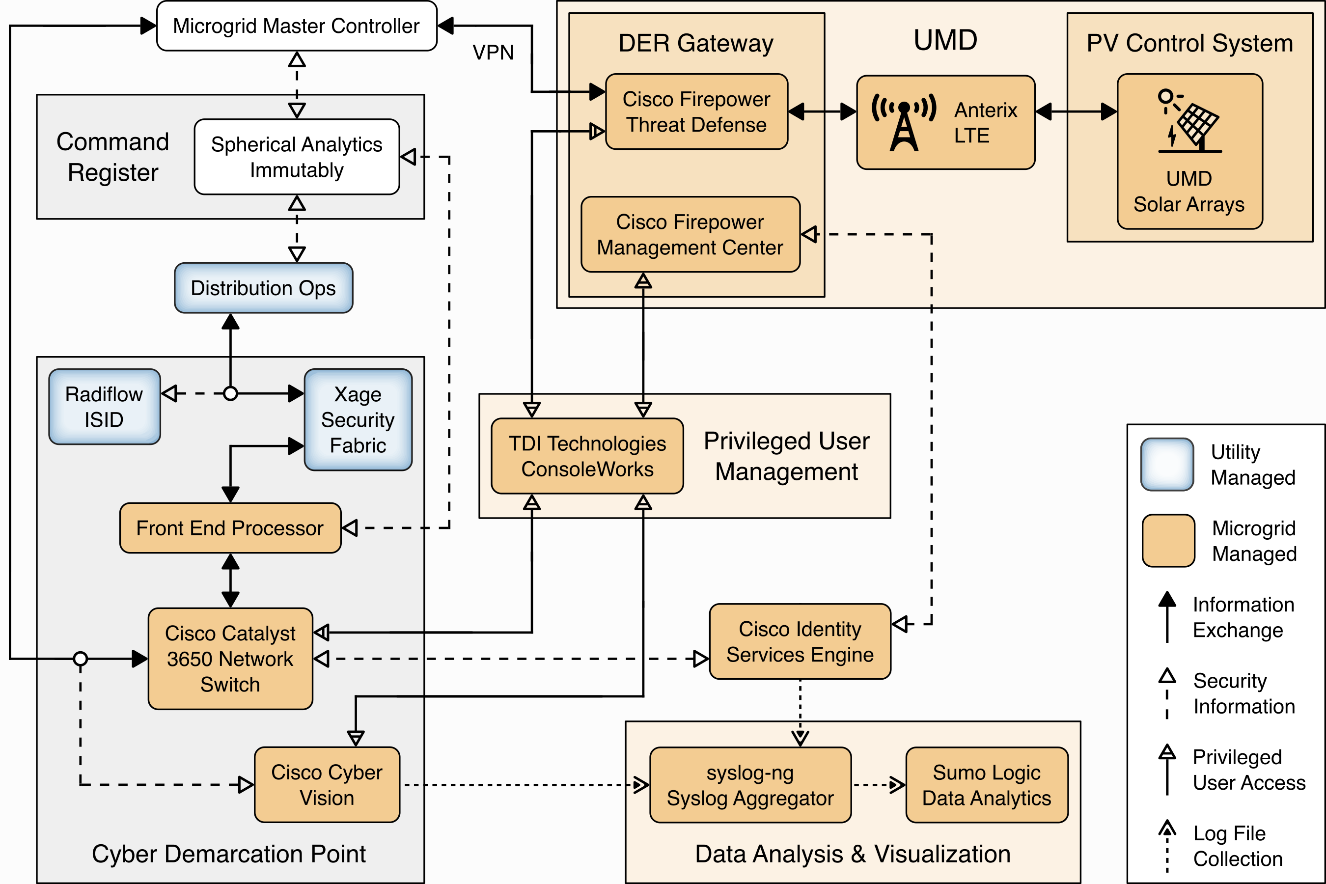
The Xage Security Fabric is used to implement the utility identity management and utility GW component of the reference architecture. The Xage Security Fabric consists of five services, the Xage Broker, the Xage Manager, Xage Center nodes, a Xage Edge Node, and a Xage Enforcement Point. Installation and configuration of the Xage Security Fabric are described in Section 2.8.
Radiflow iSID is used to implement the utility monitoring component of the reference architecture. iSID is a single virtual appliance. Installation and configuration of Radiflow iSID are described in Section 2.4.1.
A Cisco Catalyst 3650 ISE-capable switch implements the microgrid GW component of the reference architecture. This switch requires the front-end processor to authenticate to connect. Further, the switch is the policy enforcement point for access decisions made by ISE. ISE policy only allows the front-end processor to communicate with the Microgrid Master Controller.
A Cisco Firepower Threat Defense next-generation firewall implements the DER GW component of the reference architecture. This firewall requires the Microgrid Master Controller to authenticate to connect. Further, the firewall is a policy enforcement point for access decisions made by ISE. ISE policy only allows the Microgrid Master Controller to communicate with DERs.
Cisco Cyber Vision implements the microgrid monitoring component of the reference architecture. Cyber Vision is a single virtual appliance. Installation and configuration of Cisco Cyber Vision are described in Section 2.2.
The UMD solar arrays are not connected to the UMD campus network. Anterix designed and installed an LTE network to connect the solar arrays with our VPN enabling communication from the NCCoE lab to the solar arrays. Section 2.1 describes the Anterix design and implementation.
Cisco Identity Services Engine (ISE) provides the microgrid identity management component of the reference architecture. Authenticated identities and access policy decisions from Cisco ISE are enforced by the Cisco ISE-capable switches to control access to the Microgrid Master Controller and the DERs. Installation and configuration of Cisco ISE are described in Section 2.3.
Spherical Analytics Immutably implements the command register. Distribution ops systems, the front-end processor, and the microgrid master controller all send copies of information exchanges to Immutably’s distributed ledger. Immutably is cloud-based software-as-a-service. Our configuration and use of Immutably are described in Section 2.5.
The distribution ops system, the front-end processor, and the microgrid master controller are emulated by NCCoE-developed software that sends copies of Modbus commands destined for the UMD solar arrays to Immutability.
The control systems of the UMD solar arrays represent the PV control system.
Sumo Logic implements the data analytics and visualization element of the reference architecture. Syslog data from the products and services in the cyber demarcation point and the microgrid are sent to Sumo Logic for aggregation, analysis, and visualization. Sumo Logic is a cloud-based software-as-a-service. Our configuration and use of Sumo Logic are described in Section 2.6.
TDi Technologies ConsoleWorks provides the privileged user management for products and services used on the microgrid. Access by privileged users to manage Cisco CyberVision and Cisco ISE is controlled by ConsoleWorks. Installation and configuration of ConsoleWorks are described in Section 2.7.
pfSense is used to create a virtual private network between the NCCoE lab and UMD. pfSense is also used to control traffic out of the virtual lab to the Sumo Logic and Spherical Analytics cloud services. pfSense installation and configuration are described in Section 2.9.
syslog-ng is used to aggregate syslog data from products and services before sending the data to Sumo Logic. Installation and configuration of syslog-ng are described in Section 2.10.
2 Product Installation Guides
This section of the practice guide contains detailed instructions for installing and configuring all the products used in the example solution.
2.1 Anterix Long Term Evolution (LTE) Network
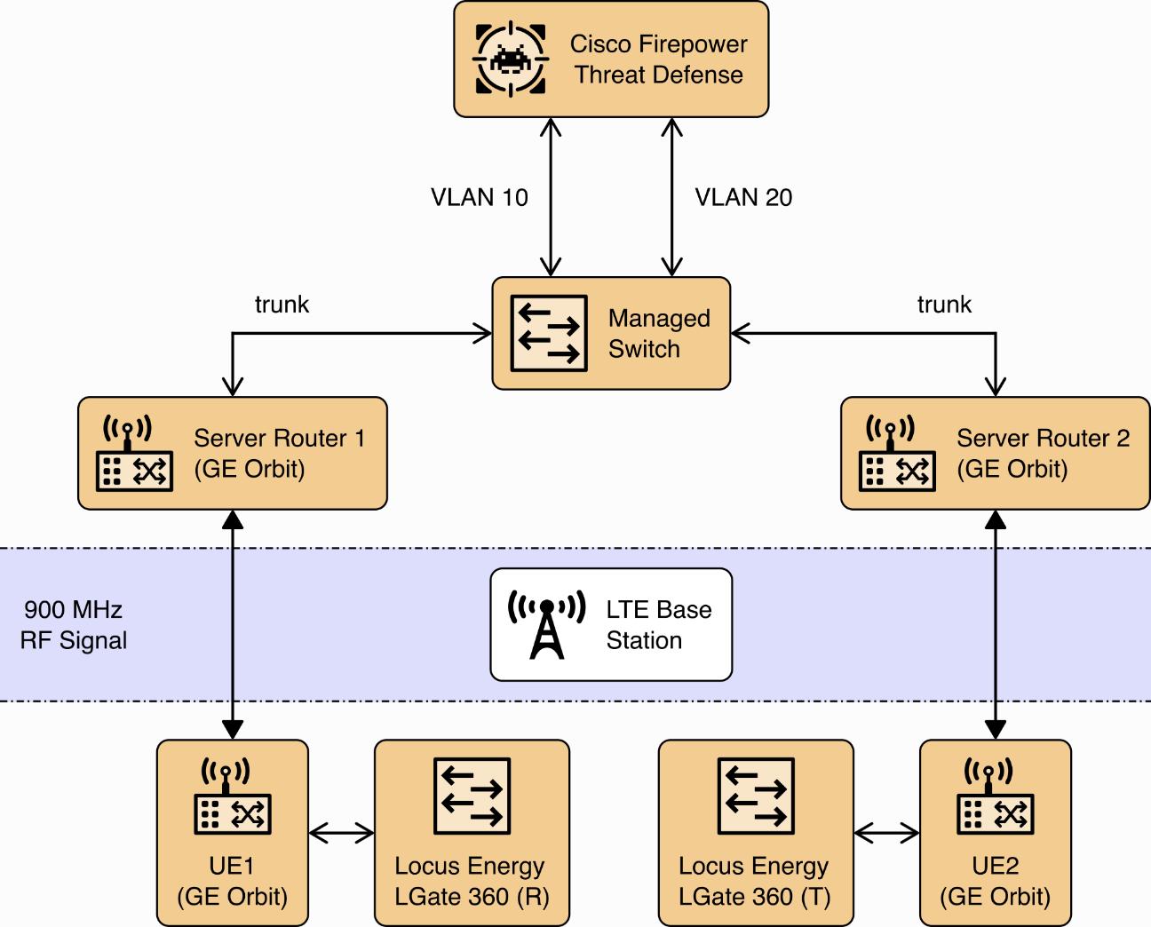
Anterix installed an LTE cellular network at UMD to provide connectivity from Clark Hall, where the NCCoE ESXI server is located, to the Regents and Terrapin Trail parking garages where the solar arrays are located. The installation included placing a router with a cellular interface at each parking garage and a managed network switch and two routers with cellular interfaces at Clark Hall. A point-to-point VPN is established over a cellular connection from a router in Clark Hall to a router at a parking garage.
A virtual Cisco Firepower Threat Defense next-generation firewall installed on the NCCoE ESXI server at Clark Hall implements the reference architecture’s device GW. This firewall controls access to the Anterix-managed switch which provides connectivity to a cellular point-to-point VPN that connects to the solar arrays. The LGate 360s provide a connection point to the solar array control systems that implement the PV Control System of the reference architecture. Figure 2‑1 illustrates the cellular network installation.
Figure 2‑1 Anterix Cellular Network Implementation
2.2 Cisco Cyber Vision
Cisco Cyber Vision implements the microgrid monitoring component of the reference architecture. It monitors the microgrid network for anomalous activity and provides alerts via syslog. These alerts are collected and sent to the data analysis and visualization component for presentation to microgrid operators.
Cisco Cyber Vision was provided as a virtual appliance in an open virtualization appliance (OVA) file. The OVA file was deployed as a virtual machine in Sphere. We followed the instructions in Cisco’s Cyber Vision All-in-One guide to complete the installation.
After the OVA has been deployed, check and verify the first network device (eth0) is used as the management interface by ensuring it has received an Internet Protocol IP address. The second network device (eth1) should not have an IP address as that will be the monitoring port in this deployment. Note the MAC address (link/ether in the screenshot below) for eth1 for the next step. When the MAC address is noted, type
sbs-netconfto start the configuration process.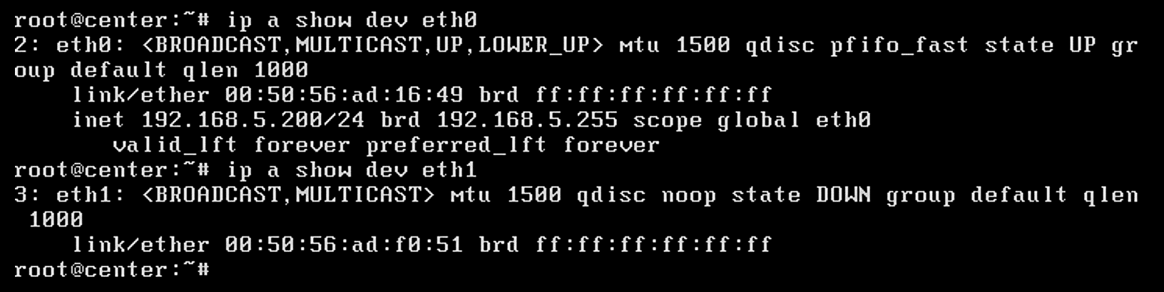
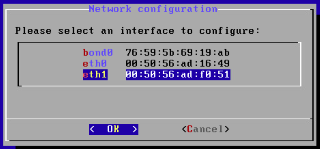
Using the MAC address in the previous step, select the correct interface to activate the monitoring connection, then click OK.
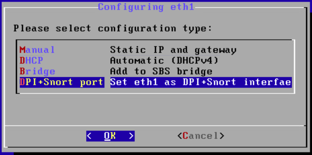
Select DPI+Snort port and click OK.
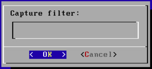
Leave the Capture filter: block empty and click OK.
Verify that the service is running by entering
systemctl status flowand verifying that the service is active and running.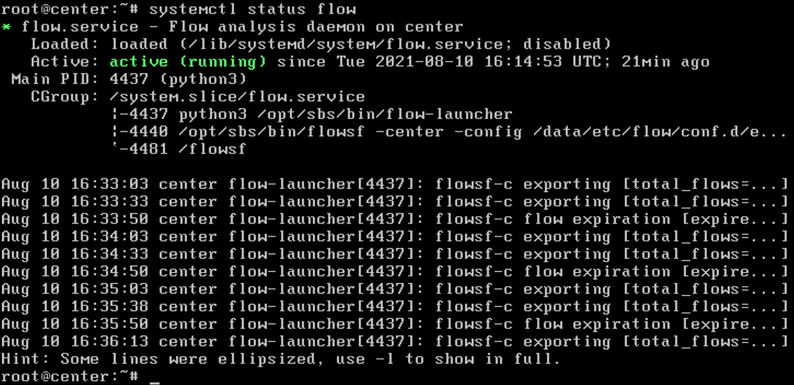
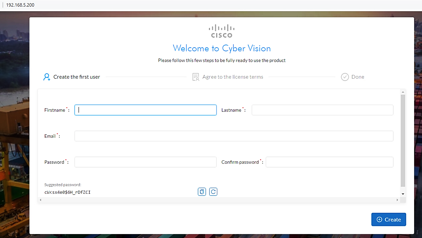
Open up a browser on a system that is network routable to the Cyber Vision system and type the IP address into the URL. The Welcome to Cyber Vision screen shown below displays. Enter the user information and click Create.
Read the EULA and click Agree.
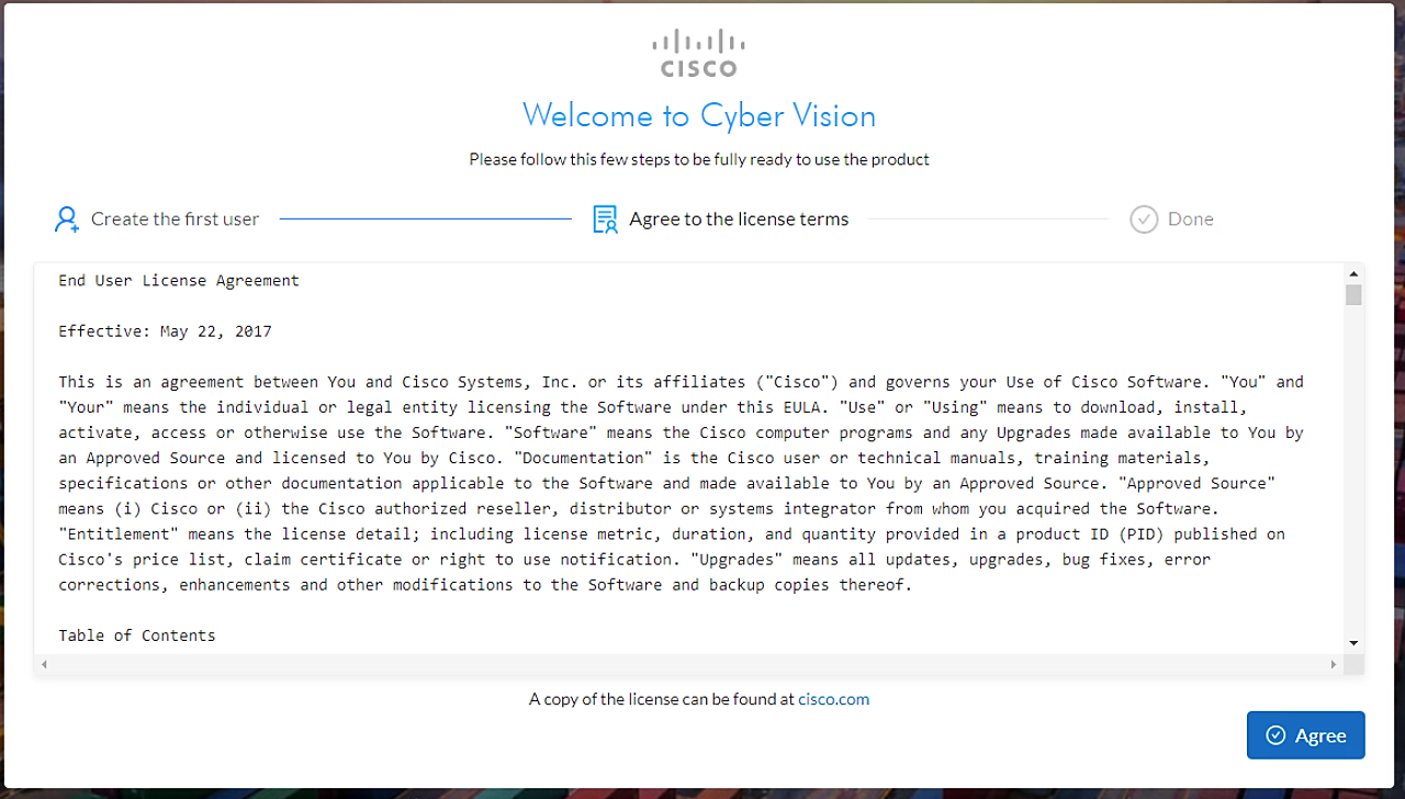
Figure 2‑2 shows the location of Cisco Cyber Vision in the example solution.
Figure 2‑2 Cisco Cyber Vision in the Example Solution
2.3 Cisco Identity Services Engine (ISE)
Cisco ISE provides the microgrid identity management component of the reference architecture. It works with Cisco ISE-enabled switches to provide authenticated identities that are used for access control.
2.3.1 Cisco ISE Installation and Configuration
ISE was installed using the ISE 2.7 Installation Guide available at https://www.cisco.com/c/en/us/td/docs/security/ise/2-7/InstallGuide27/b_ise_InstallationGuide27/b_ise_InstallationGuide27_chapter_011.html#ID-1417-00000271
We followed steps 1 through 17 in the section titled “Configure a VMware Server” with the following selections:
Step 8: Small,
16 coresStep 12: 200Gb,
thick-provisioned hard drive
After completing the installation we used the setup guide at https://www.cisco.com/c/en/us/td/docs/security/ise/2-7/InstallGuide27/b_ise_InstallationGuide27/b_ise_InstallationGuide27_chapter_010.html#id_11096 to configure ISE.
Start up the virtual machine (VM) for ISE that was created and enter
setupon the login screen: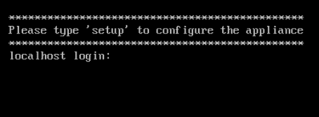
Fill in the appropriate information to configure the installation of ISE (as seen below):
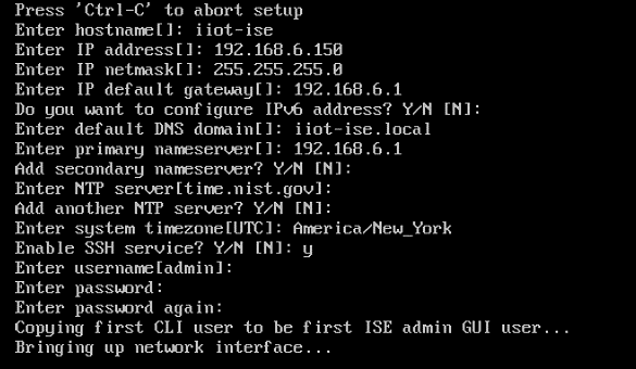
Once all configuration steps are complete, the ISE installation will begin. This may take several minutes.
Once installation is complete, log in to ISE and run
show
application status ise
to verify ISE installation is complete.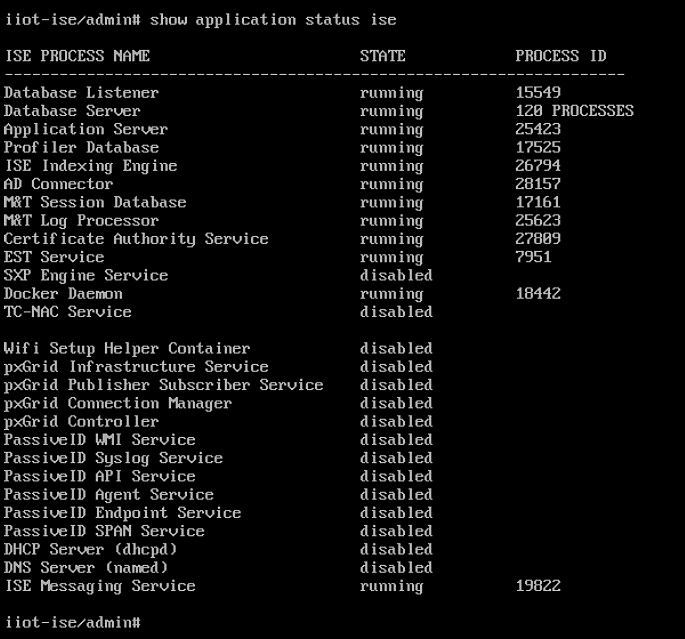
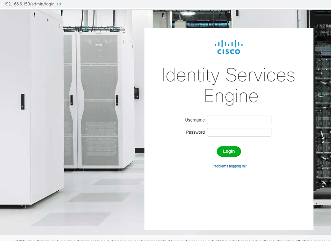
Open a web browser and log into the Cisco ISE webserver.
Once complete, go to Administration > Network Resources > Network Devices and click New Network Device. Add the switch that will be configured to control access with the settings shown below.

We configured three identities in ISE:
One identity was given access to both UMD solar arrays.
One identity was given access to only one UMD solar array.
One identity was given no access to the UMD solar arrays.
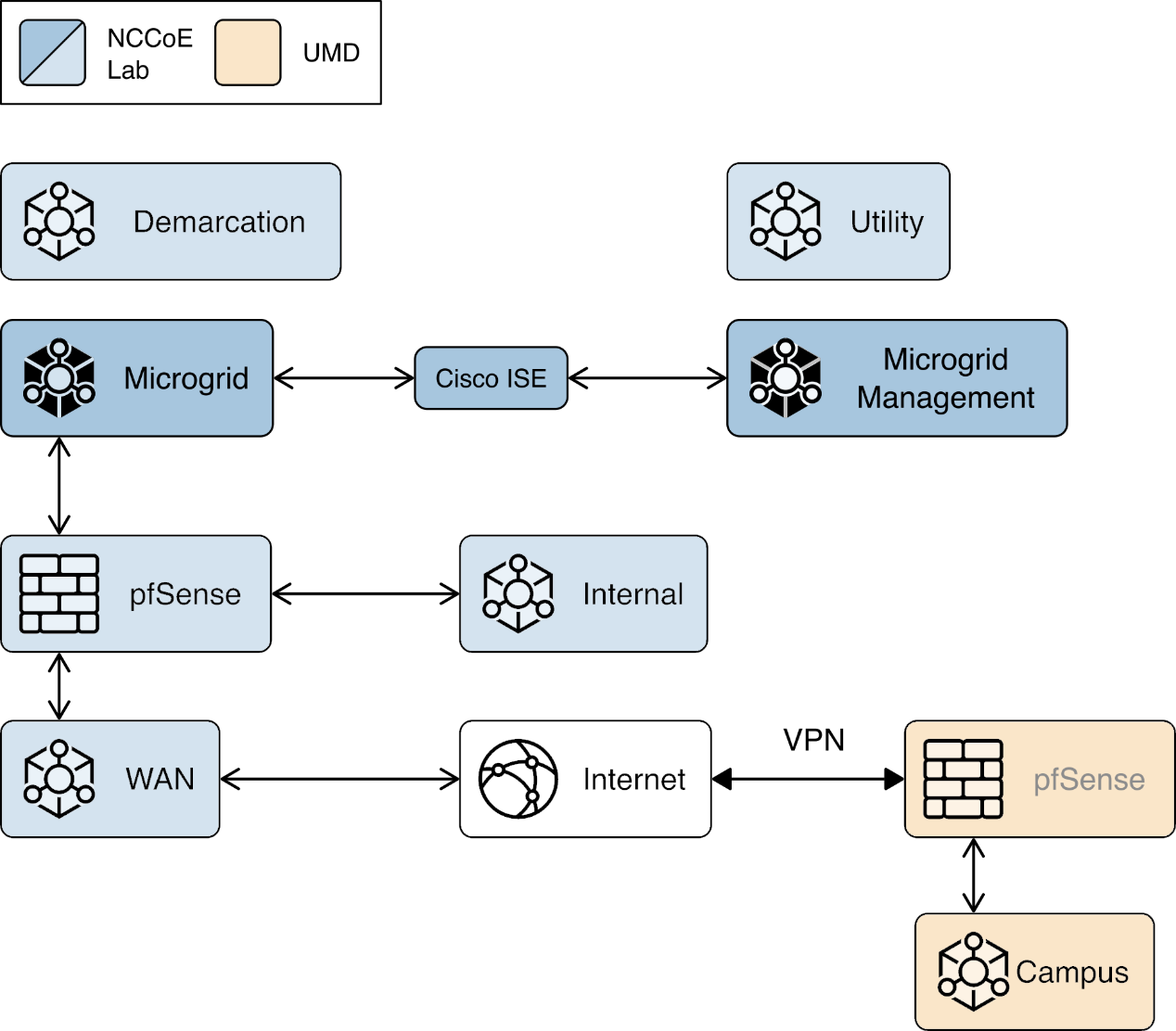
Figure 2‑3 shows how Cisco ISE in positioned the example solution.
Figure 2‑3 Cisco ISE Position in the Example Solution
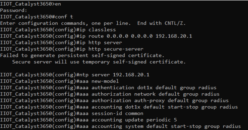
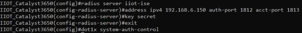
2.3.2 Cisco ISE Switch Settings
In order to integrate Cisco ISE with the switches in the NCCoE lab, switch configuration is required. Run the required commands as shown in the following two screenshots.
After completing the commands listed above, enter exit then copy
running-config startup-config to save the configuration to the switch.
2.3.3 Cisco Firepower Installation and Configuration
To handle identity authentication and authorization for protected resources at UMD, Cisco Firepower was utilized. Implementation included Firepower Management Center (FMC) and Firepower Threat Detection (FTD).
2.3.3.1 Cisco Firepower Threat Detection Installation and Configuration
Obtain OVF and VMDK file from Cisco representative and deploy to virtual environment. Power on VM after deployment is completed.
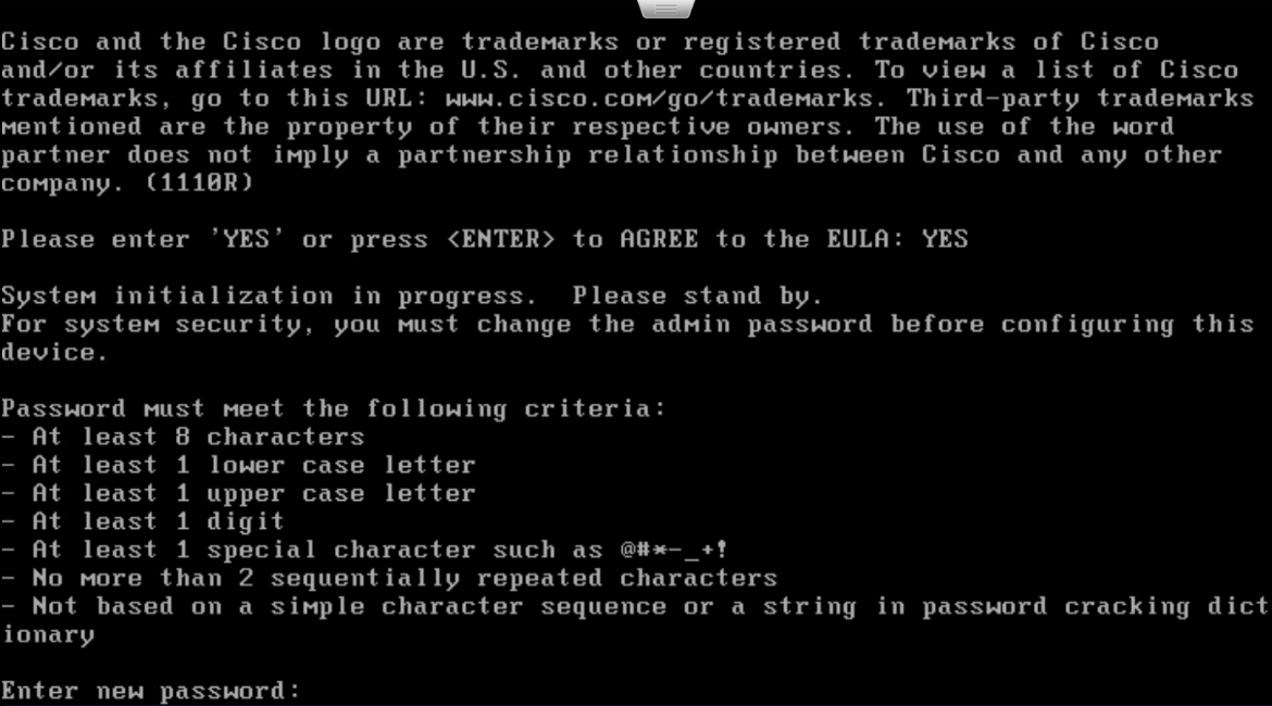
Open VM Console and log in with username admin and password Admin123. Once logged in, view and accept the EULA.
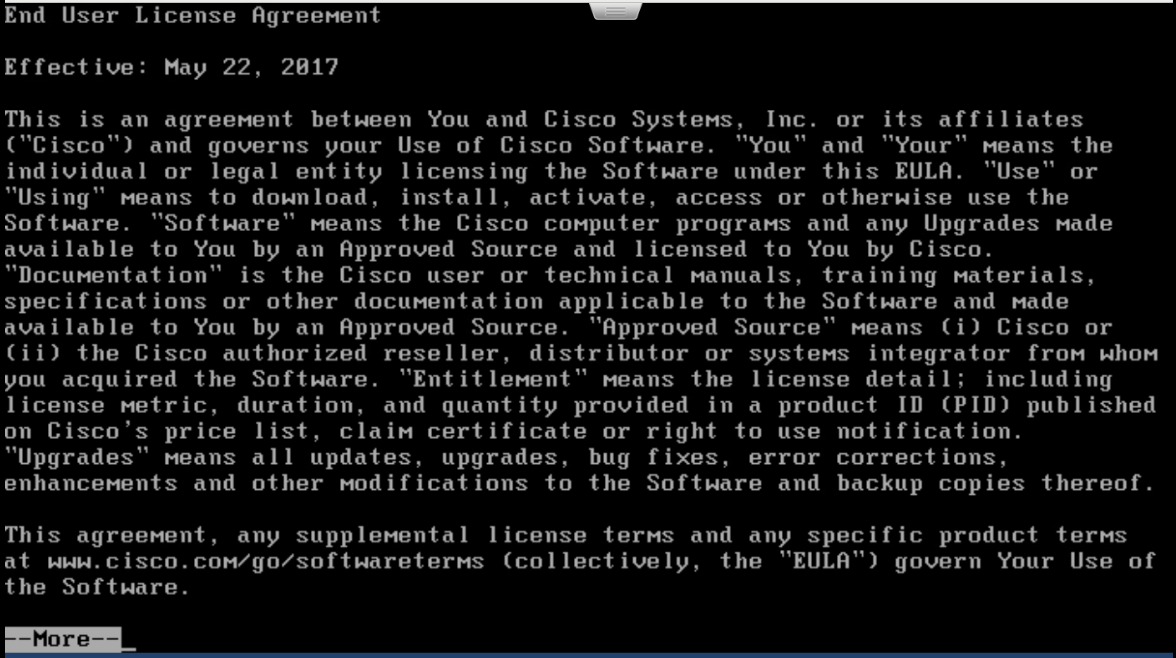
Once completed, create a new password for the admin user.
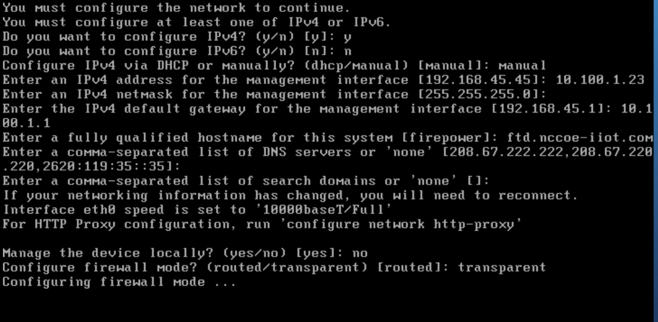
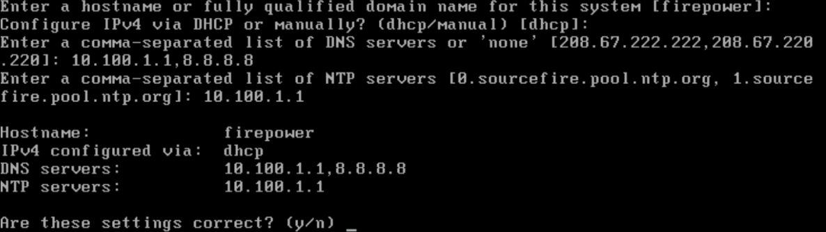
Setup and configure network settings for FTD. Ensure that the device will not be managed locally and that the FTD system will run in transparent mode.
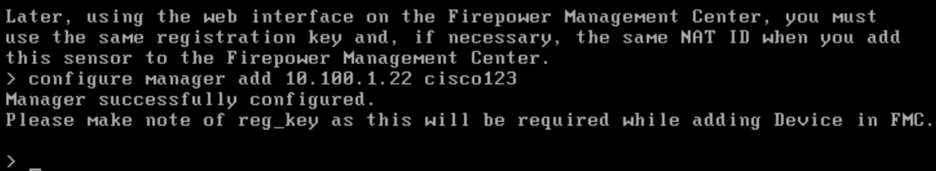
Configure the manager settings with the IP address of ISE and a registration key. The key opted to use in this build is cisco123. This key is required for integration into FMC.
2.3.3.2 Cisco Firepower Management Center Installation and Configuration
Obtain OVF and VMDK file from Cisco representative and deploy to virtual environment. Power on VM after deployment is completed.
Open VM Console and log in with username admin and password Admin123. Once logged in, view and accept the EULA.
Configure network for FMC system. DHCP was utilized in this setup. Type y to verify configuration.
Once logging in to the web interface for FMC, click the gear icon in the top left, then select Integration. Select the tab at the top entitled Identity Sources.
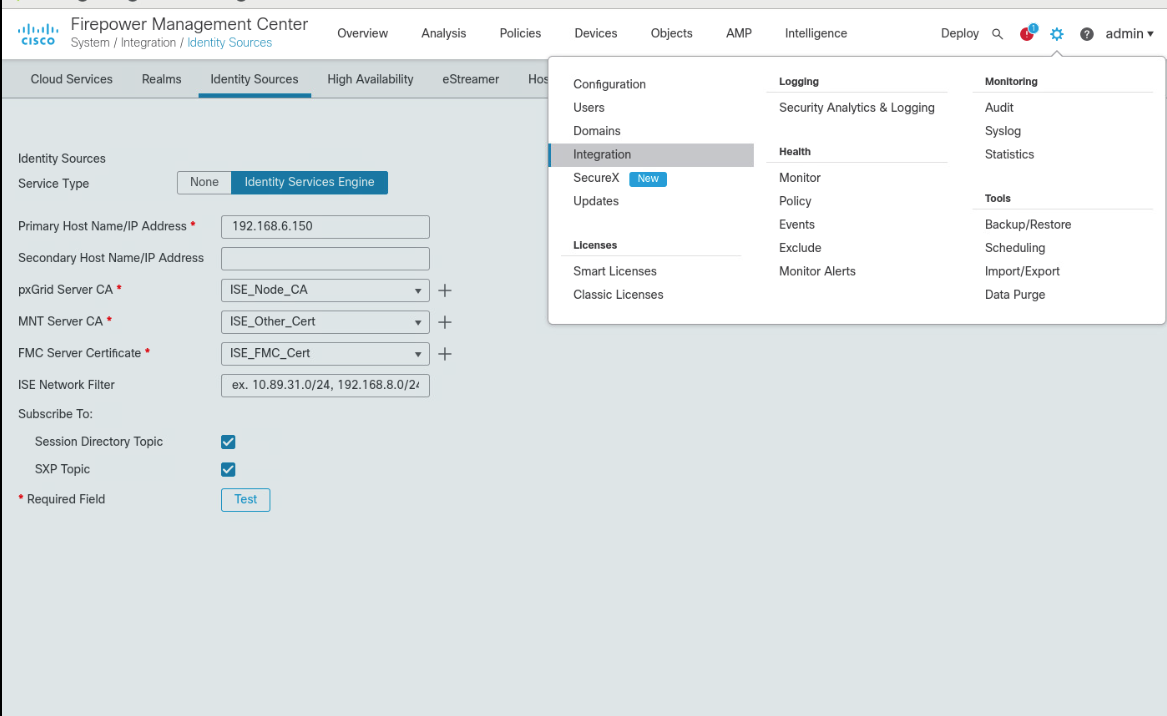
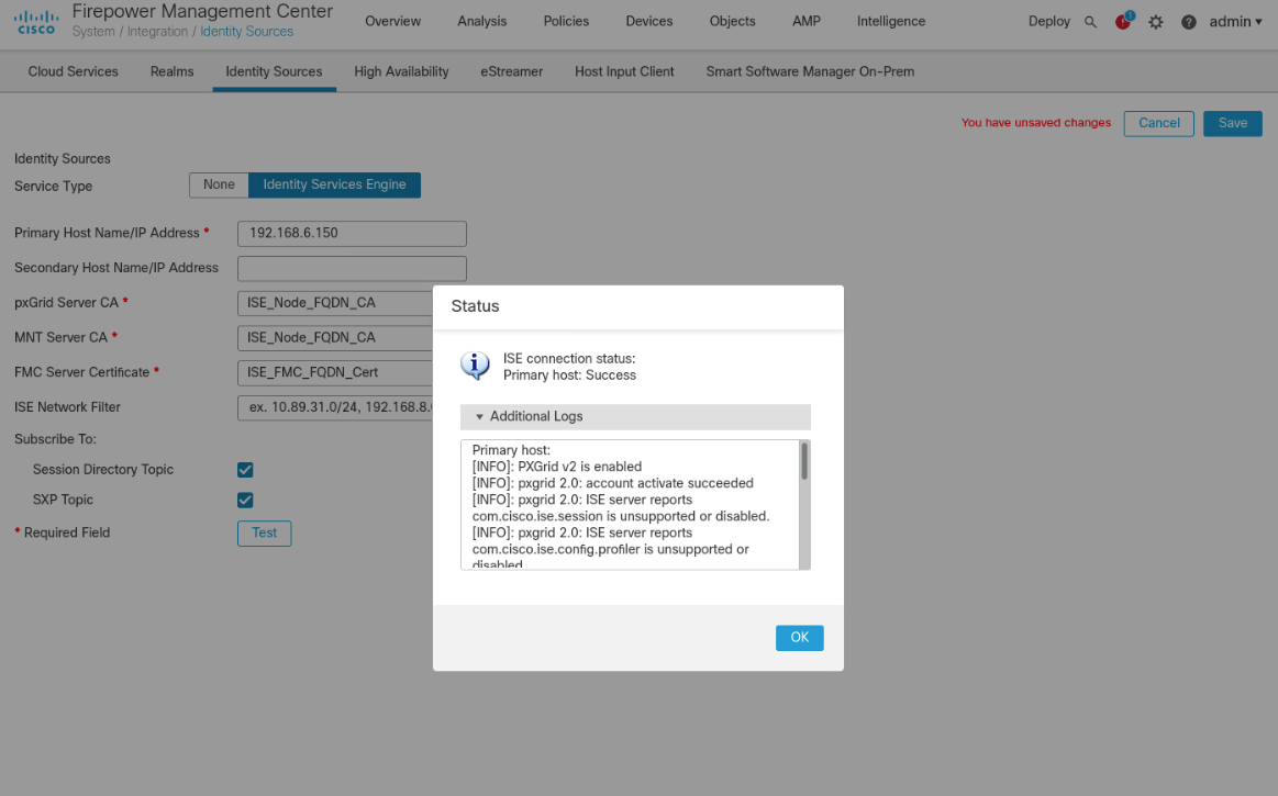
Fill out each line for the ISE instance. IP address or Fully Qualified Domain Name (FQDN), the pxGrid Server certificate authority is the self-signed certificate in ISE, the same certificate is used for the MNT certificate, and the FMC Server Certificate is the certificate generated in ISE for the pxGrid. Ensure that the checkboxes for Session Directory Topic and SXP Topic are selected. Click Test to verify successful connection, then click Save.
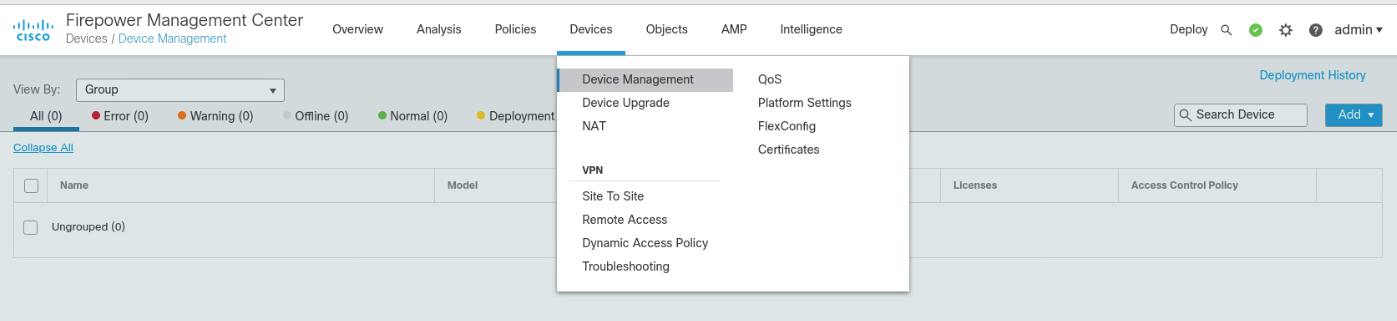
To add the FTD, select Device > Device Management, then click Add.
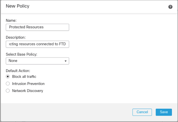
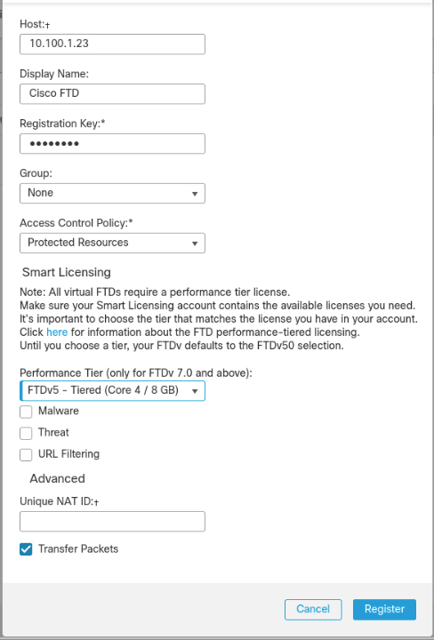
On the pop-up window, fill in all blanks, with the Host as the IP address of the FTD, a Display Name, and place copy the registration key created earlier to Registration Key. The lab used cisco123 as the registration key. For Access Control Policy, click the drop-down box, then select Create New Policy. Give it a name, description, and ensure Block all traffic is selected as the default action. Click Save.
Select FTDv5 for the Performance Tier and click Register.
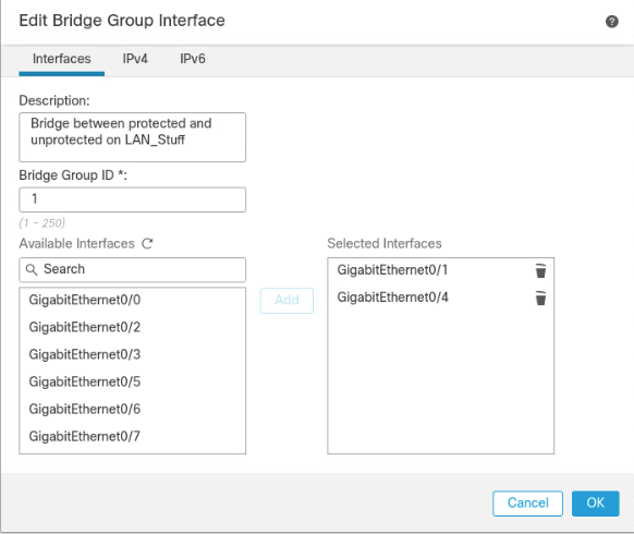
The final setup required is to add a virtual interface. On the Device Management page, click the Interfaces tab if it is not already added, then click Add Interfaces on the left side of the screen. Then select Bridge Group Interface. Here we selected one interface for each side of the transparent connection, then on the IPv4 tab assigned an IP address. The click OK.
2.4 Radiflow iSID
We implemented the utility cyber monitoring element of the reference architecture using Radiflow iSID. iSID is a passive monitoring, analysis, and detection platform that can be provided as either a physical or logical appliance. iSID learns the basic topology and behavior of the industrial control devices on the networks that it monitors. A typical deployment places an iSID appliance at a central location on the utility network and deploys iSAP smart collectors to various locations of interest on the utility network. In the example solution, for example, we could have placed smart collectors at UMD and in the NCCoE lab. To simplify the NCCoE lab example solution, a single virtual appliance was deployed in the NCCoE lab that acts as both the analysis and detection engine and the network collector.
iSID allows the utility operator to see all devices connected to the utility network, detect anomalous behavior on the network, and detect policy violations in communications occurring over the network. This information is made available to utility cyber analysts both through a collection of dashboards and through syslog data that can be collected by a Security Information and Event Management (SIEM) system.
In the NCCoE example solution, iSID was placed on the utility virtual network (vLAN) between the distribution ops systems and the utility GW. This placement provides information about traffic bound for the microgrid network from the utility network. Sensors could also be placed between the utility GW and the front-end processor.
2.4.1 Radiflow iSID Installation and Configuration
This section discusses the Radiflow iSID installation and configuration procedures.
Setup a Radiflow Installation Manager (RIM) Server
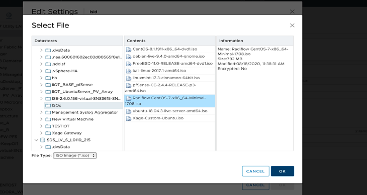
Create a Radiflow virtual machine (VM) using CentOS 1708 minimal International Standards Organization (ISO) file – CentOS-7-x86_64-Minimal-1708.iso.
Once the VM is up, use it to download the RIM from the download site.
Download the file from the website for install.
We downloaded the file on the TEST machine, and then secure copied it to the Radiflow machine we created. Inside the Radiflow VM, files are uploaded into the ‘radiflow’ directory in the radiflow home directory (cd/radiflow). The files include iSID latest version – isid-5.7.7.13.5-0.tar, Radiflow Installation Manager (RIM) – rim-5.7.7.13-0.tar and iSID Signature file - isid-5.7.7.13.5.signature.txt– needed for installing iSID using RIM.

Extract RIM and run it.
tar -xvf rim-5.7.7.13-0.tarcd rim-5.7.7.13-0su root./start.sh
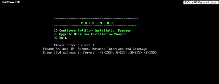
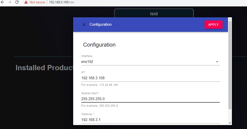
Enter
1to configure the RIM server with the following:IP address: 192.168.3.108
Subnet mask: 255.255.255.0
Gateway: 192.168.3.1
Interface name: ens192
Access and Test the RIM and iSID User Interface
To access the RIM, open a web browser from the TEST VM (192.168.3.101) and navigate to the RIM server at https:192.168.3.108/rim.
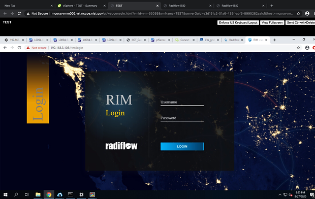
To get access inside the RIM user interface login, enter the username and password:
Username: radiflow
Password: Secured1492
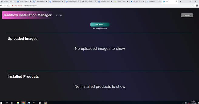
Inside this TEST machine, we have the files isid-5.7.7.13.5-0.tar and iSID Signature file isid-5.7.7.13.5.signature.txt
Click Browse and select the isid-5.7.7.13.5-0.tar.
Click Add signature file and select isid-5.7.7.13.5.signature.txt, then click Upload.
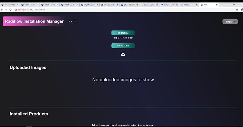
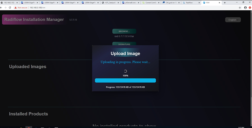
Successfully uploaded the image.
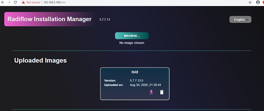
Install the uploaded image.
Note: If you configured the RIM server from step 6 above, then there is no need to reconfigure.
Product installation window:
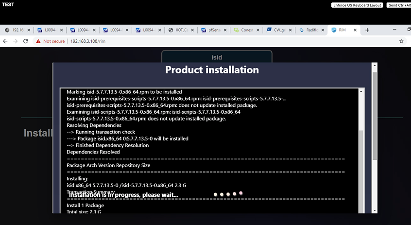
Once the installation is complete, the installed iSID image displays.
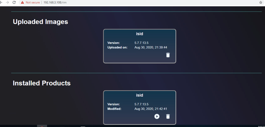
Run an installed iSID image, click Finish when it is complete.
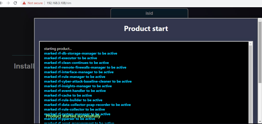
Test the installed and running iSID.
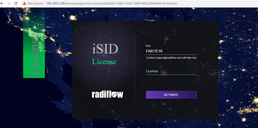
Navigate to https://192.168.3.108/isid to enter the activation key:
Contact Radiflow to get the license and enter the license key and select Activate. We need to enter: E7ICAMY8.
Enter the following credentials for iSID:
Username: radiflow
Password: safe@Rad1flow
View the Radiflow iSID web application.
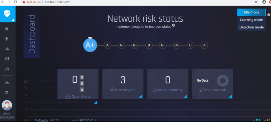
Figure 2‑4 shows the location of Radiflow iSID in the example solution.
Figure 2‑4 Radiflow iSID position in the example solution
2.5 Spherical Analytics Immutably TM
We implemented the command register element of the reference architecture using the Spherical Analytics Immutably service. Immutably receives records of information exchanges from the distribution ops systems, the front-end processor, and the microgrid master controller. It digitally signs the records, augments them with information from notaries providing time stamps and source information, and places them on a distributed ledger. This ledger provides an immutable audit trail of information exchanges between the utility and microgrid DER devices.
The records in the ledger are cryptographically chained together to provide tamper detection. The utility and all participating microgrid operators can read and verify the audit trail maintained by the Immutably distributed ledger.
2.5.1 Spherical Analytics Immutably Installation and Configuration
Immutably is a software-as-a-service product and no installation was required. We developed three pieces of software to send data to Immutably. The source for this software is provided in Appendix B.
The records are sent using an Immutably representational state transfer (REST) application programming interface.
2.6 Sumo Logic
Sumo Logic provides a cloud-based SIEM capability for analyzing and visualizing security information and events that implement the data analysis and visualization elements of the reference architecture. Sumo Logic data analytics and visualization are software-as-a-service products. No installation was required for the analytic and visualization services. Figure 2-5 shows Sumo Logic’s role in the reference architecture.
Figure 2‑5 Sumo Logic Role in the Example Solution
2.6.1 Sumo Logic syslog Collector Installation
We installed the Sumo Logic syslog collector on a Linux system to send syslog data to Sumo Logic for analysis. The Sumo Logic collector provides one of the two parts that make up the log collection element of the reference architecture. We combined the Sumo Logic syslog collector with the open-source version of syslog ng to create the log collector element of the reference architecture.
We set up an Ubuntu Linux VM and installed the collector using a command provided by Sumo Logic:
sudo wget "https://collectors.us2.sumologic.com/rest/download/linux/64” -O
SumoCollector.sh && sudo chmod +x SumoCollector.sh && sudo
./SumoCollector.sh && chmod +x SumoCollector.sh

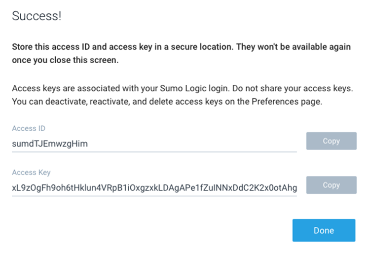
Next, an authentication method is required to get the access key and access ID or installation token strings from the Sumologic account, which will be used to register installed collectors. Navigate to Preferences from the menu options.
Click Add Access Key and add a username for your collector.
Click Create Key to see the access ID and Access Key you created.
Run the command:
sudo ./SumoCollector.sh -q -Vsumo.accessid=<accessId>
-Vsumo.accesskey=<accessKey> -Vsources=<filepath>
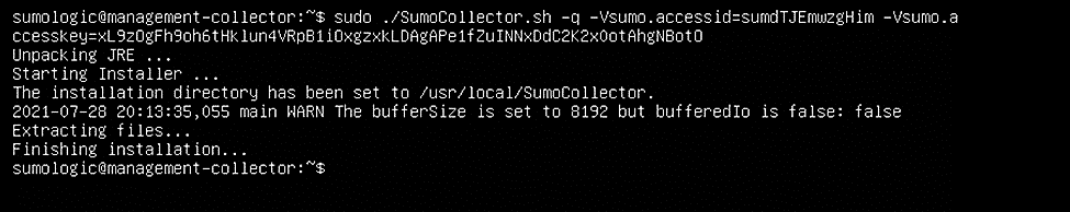
Figure 2‑6 shows the location of Sumo Logic collectors and Sumo Logic Software as a Service in the example solution.
Figure 2‑6 Sumo Logic Location in the Example Solution
2.6.2 Configuring Sources for syslog Collectors
For each installed collector, we are using Syslog or remote file as our source type. Each product’s log data goes to a syslog aggregator, implemented with Syslog ng, before reaching the Sumo Logic collector. Installation and configuration guide for Syslog-ng is described in Section 2.10.
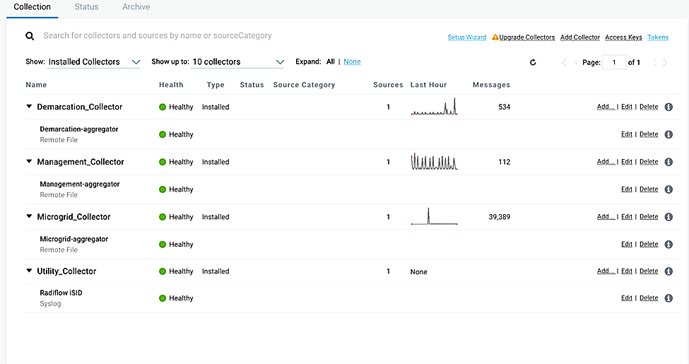
Navigate to Manage Data > Collection on the Collector menu.
Click Add Source for Collector management-collector.
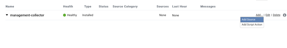
Select the Remote File source and provide the following information for source and destination:
Name:
management-aggregatorHost:
193.168.20.116Port:
22Path Expression:
cd /var/log/syslog-ng/logs.txt
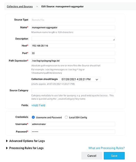
Click Save.
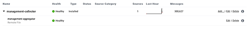
We configured four collectors, one for each of the eight networks used in the example solution, microgrid, microgrid management, demarcation, and utility. This configuration is shown below.
2.7 TDi Technologies ConsoleWorks
TDi Technologies ConsoleWorks serves as a ”jump box” to control privileged user access to the management interfaces of Cisco ISE and Cisco Cyber Vision. ConsoleWorks maintains the credentials used to access the dedicated management interfaces of these products. Privileged users have credentials that allow them to access ConsoleWorks. ConsoleWorks uses “user profiles” to define the management interfaces that each privileged user is allowed to access, and the credentials used to access that interface. ConsoleWorks authenticates authorized users to product management interfaces and records all privileged user actions in an audit trail.
2.7.1 Console Works Installation and Configuration
Create a virtual machine running Centos 7.5 with one network interface,
dynamic host configuration protocol disabled, and an IP address
192.168.20.109, then:
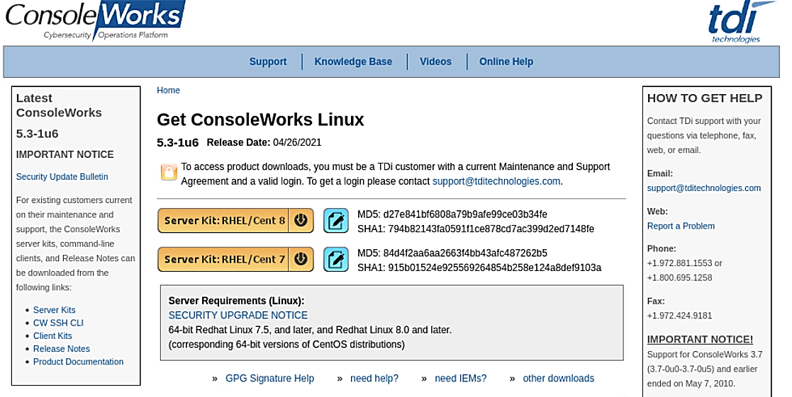
Download the installation kit from the TDi website at http://support.TDitechnologies.com. A username and password are required. Contact TDi Support at support@TDitechnologies.com to request a username and password. You will also need a unique link from TDi Technologies for the ConsoleWorks License ZIP file. Download this file (do not unzip it) to your chosen directory.
Create a directory to contain the ConsoleWorks installation files:
$mkdir -p temp/conworks.Inside the new directory, run the install script:
$sudo ./cw_install.sh.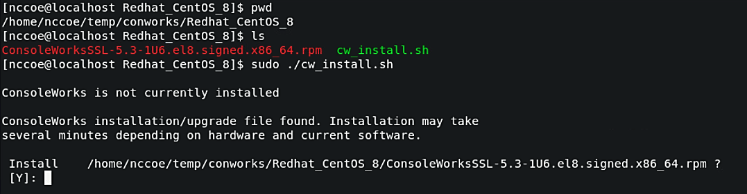
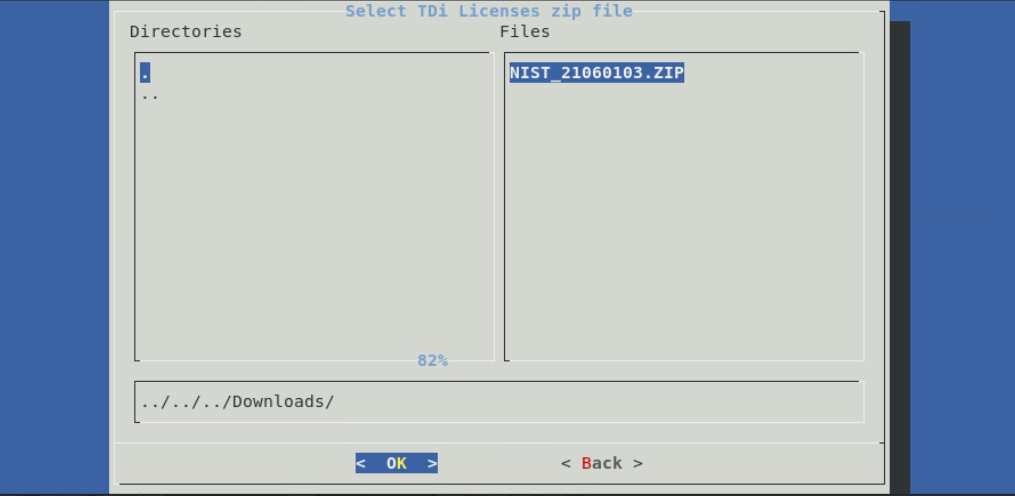
Follow the installer script to select the previously downloaded license file.
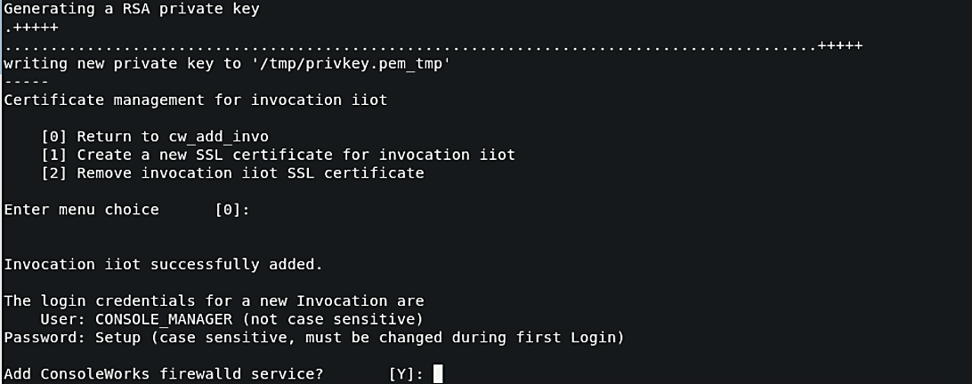
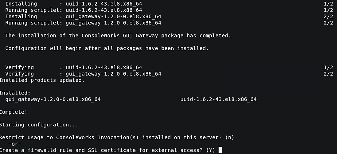
Follow the prompts to add an invocation, configure the firewall, install the Graphical Gateway, and any other network management settings.
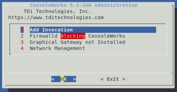
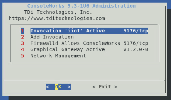
When the ConsoleWorks Administration script shows the details of the invocation and firewall settings, installation is complete. Click Exit to close the script.
If ConsoleWorks did not autostart, run the following command:
# /opt/ConsoleWorks/bin/cw_start <invocation name>.Log in to the ConsoleWorks local instance at
https://localhost:5176(or a different port number if configured) with the username CONSOLE_MANAGER and the password “Setup”. You will be required to set up a new password when complete.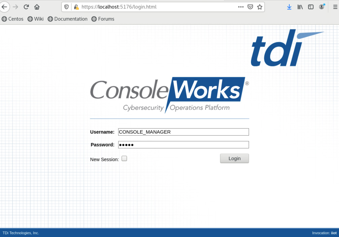
Three privileged users were defined in ConsoleWorks:
One user has permission and credentials to access Cisco Cyber Vision.
One user has permission and credentials to access Cisco ISE.
One user has permission and credentials to access both Cisco Cyber Vision and Cisco ISE.
Figure 2‑7 shows ConsoleWorks position in the example solution.
Figure 2‑7 ConsoleWorks Position in the Example Solution
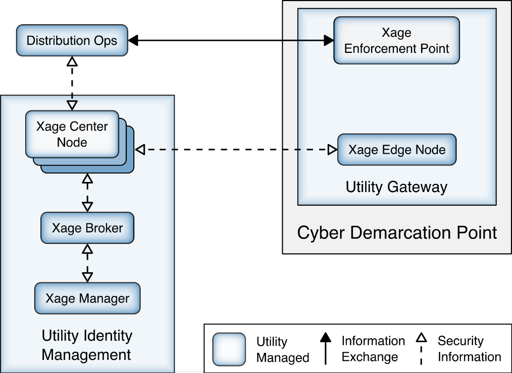
2.8 Xage Security Fabric
The Xage Security Fabric implements the utility identity management and utility GW elements of the reference architecture. The fabric consists of five services, the Xage Manager, Xage Broker, Xage Cener Fabric Node, the Xage Edge Node, and the Xage Enforcement Point. The Xage Manager, Xage Broker, and Xage Center Nodes combine to implement the utility identity management element. The Xage Edge Node and Xage Enforcement Point implement the utility GW.
The Xage Manager configures users, devices, and access policies. The policies are then sent to Xage Broker. There is one Xage Manager operated by the utility and used to configure security policies for access to all DERs.
The Xage Broker is a liaison between the Xage Manager and the Xage Center Nodes. The broker copies information such as identities and credentials from the Xage Manager to the Xage Edge nodes. In the NCCoE example solution, there is one Xage Broker operated by the utility to distribute access policies for all DERs via the distributed ledger operated on the Xage Center Nodes.
The Xage Center Nodes use a distributed ledger to provide a geographically distributed information store that is tamper-resistant. The Xage Broker distributes policy information to the Xage Center Nodes. This distributed information store provides policy information for the Xage Edge Nodes.
A Xage Edge Node is in the cyber demarcation point at each microgrid operator site. The Xage Edge Node retrieves security information for its site from the Xage Center Nodes and stores it locally within the cyber demarcation point.
The Xage Enforcement Point (XEP) in the cyber demarcation point uses the security information to allow or deny access to the front-end processor.
Figure 2‑8 Xage Implementation of Reference Architecture Elements
2.8.1 Xage Installation and Configuration
Xage provides a Linux ISO file configured with all the packages needed by the Xage services. We used this ISO to create all the VMs needed by the installation.
We followed the instructions in the XSG_Release_3.2.0_Install guide provided by Xage.
Starting on page 7 of the guide, we used Xage Built ISOs (2.1.1)
Starting on page 13, the install happens.
We created the VM for the Xage Manager using the provided ISO
The Xage Manager IP address id 192.168.3.102.
We then created three more VMs using the Xage-provided ISO, one each for:
Xage Broker
Xage Center Fabric Node
Xage Edge Node
During the install starting on page 13, we configure the Xage manager with the IP addresses of the three different VMs, and the Xage manager deploys the appropriate software to those other VMs.
Begin the install and follow the Custom ISO install guide: Create a VM with 2 cores in the CPU, 8Gb RAM, and 60Gb Hard Drive size. Load the Xage Custom ISO into the virtual CD Drive and start the installer. Once completed, continue with the install.
During the install, Xage creates a user that is used with the username xage and password secret. Log in to the VM using these credentials.
Type
sudo vi /etc/ssh/sshd_config(or a different text editor) and ensure PubkeyAuthentication and PasswordAuthentication are uncommented and are set to yes. Then runifconfigto get the IP address from the ethernet device.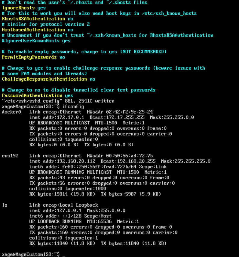
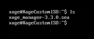
Using secure copy (SCP), copy the xage SEA file for installation to the Xage home drive.
Beginning with the install guide, we opted to utilize Xage for managing users and user groups internally (as opposed to LDAP or Active Directory).
Begin installation by running
sudo bash xage_manager-3.3.0.seaand accepting the EULA. Xage will then extract all the files.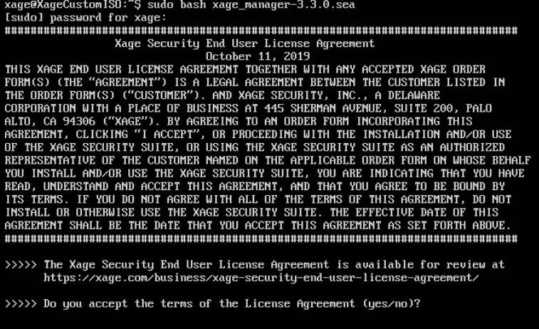
The installer will then prompt for IP addresses. Select the default. Enter
yesto accept the default configurations. Xage finishes the installation.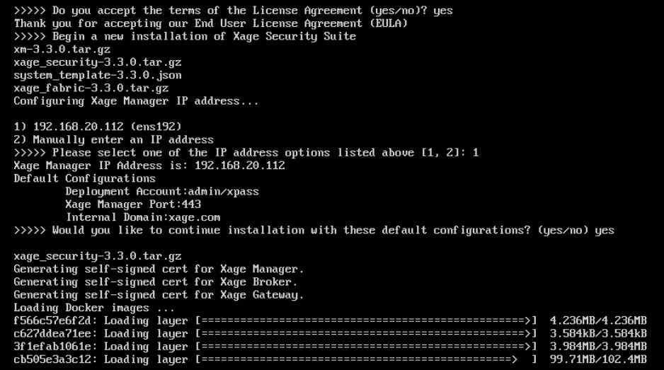
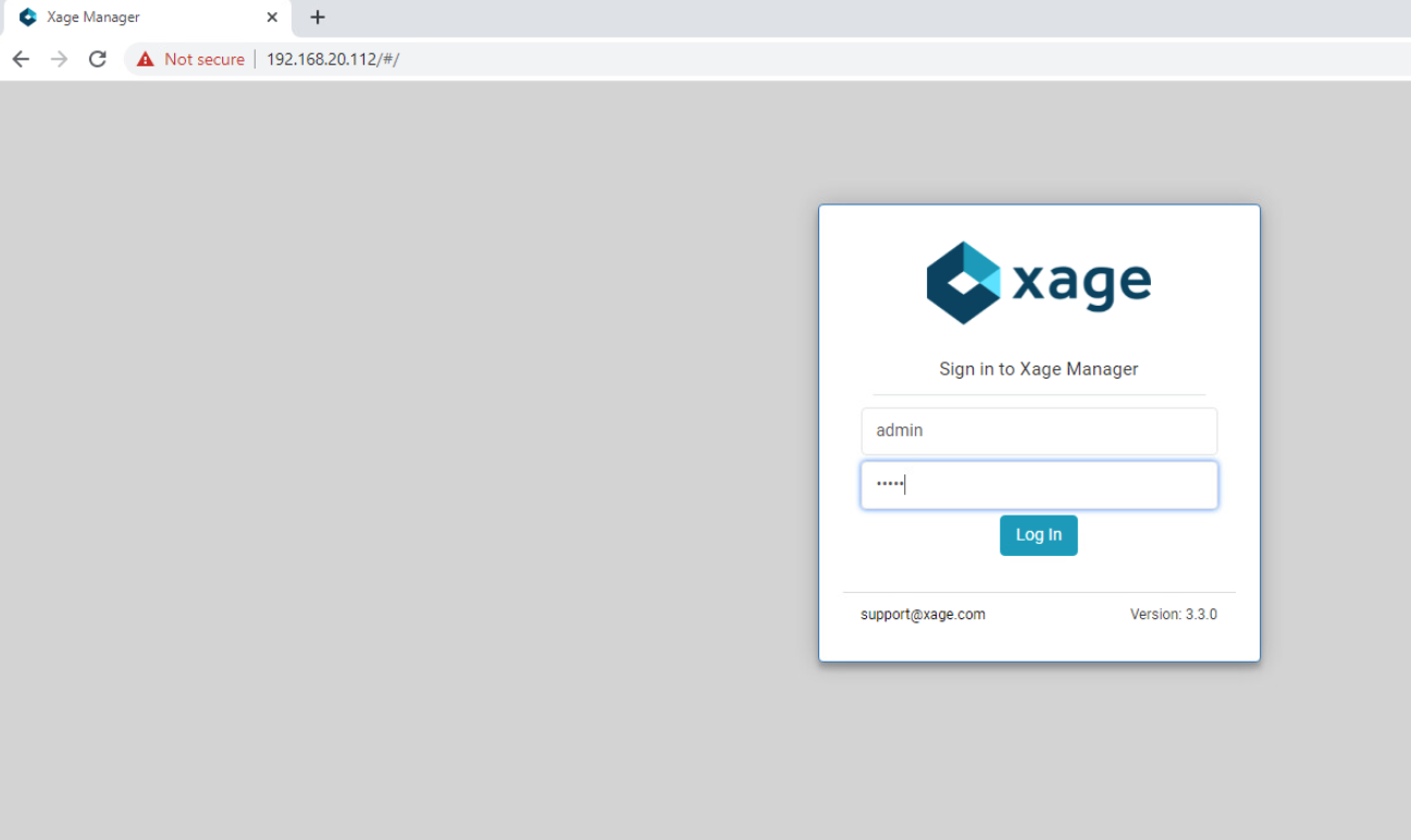
Once completed, Xage will give information on how to log in with a web server.
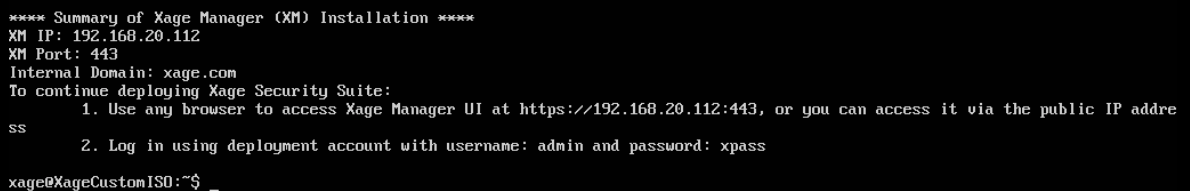
Log in to the web server at the IP address listed with the username and password listed.
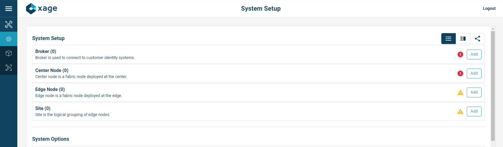
After logging in, you will be prompted to add a Xage Broker, Xage Center Node, and Xage Edge Node. These need to be VMs installed in the environment, using the Xage Custom ISO. Following Step 3 of this section we will install the required base operating systems, then use those IP addresses for the individual installations.
Gather the IP addresses of the devices that will be added. In this installation, the IP addresses are as follows:
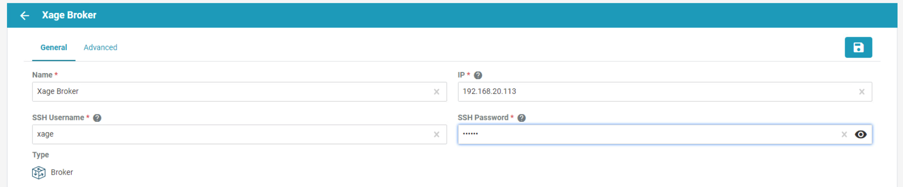
Broker: 192.168.20.113
Center Nodes (four is the minimum): 192.168.20.114, 192.168.20.117, 192.168.20.118, 192.168.20.119
Edge Node: 192.168.20.115
Starting with the Xage Broker, click Add on the far right of the Broker row. Fill in the required information and click the create icon in the top right of the frame.
Repeat the previous step for Center Node and Edge Node.
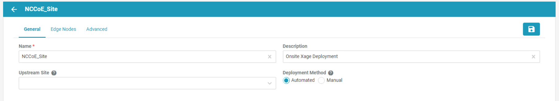
Click Add on the far right of the Site row to add a new site. The General Configuration screen opens. Fill in the information as needed.
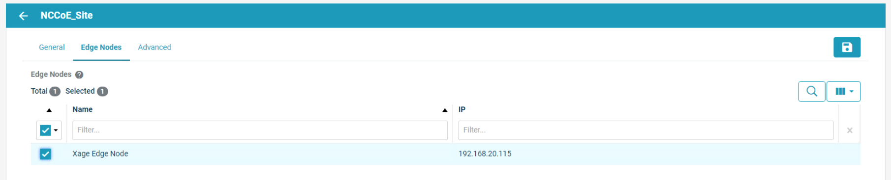
Next, click Edge Nodes on the top bar and select the Xage Edge Node created earlier then, click Create.
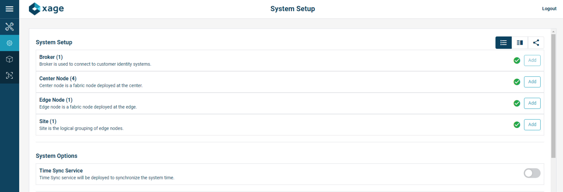
Once all devices are configured completely, the System Setup page displays all green checks.
At the bottom of the screen, Click Start to start the system. Then click Start again to confirm.
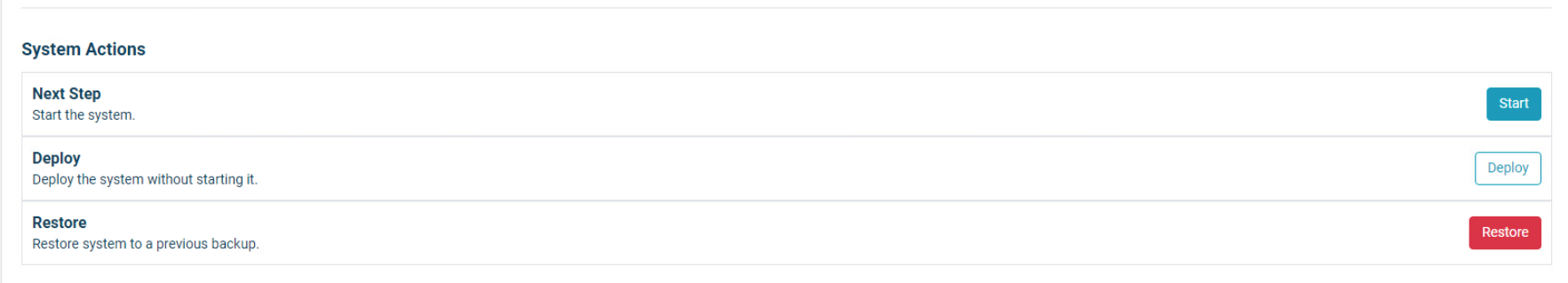
Starting begins for the system, including deploying all nodes. Current Status will show what the system is currently doing.
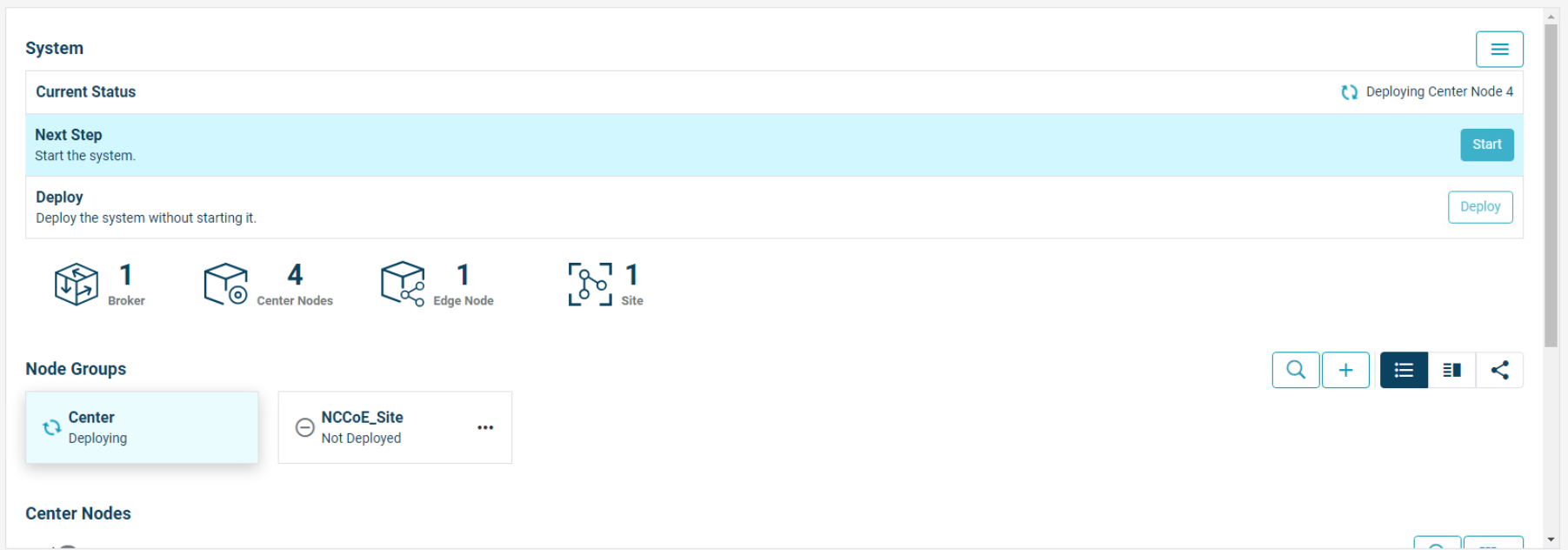
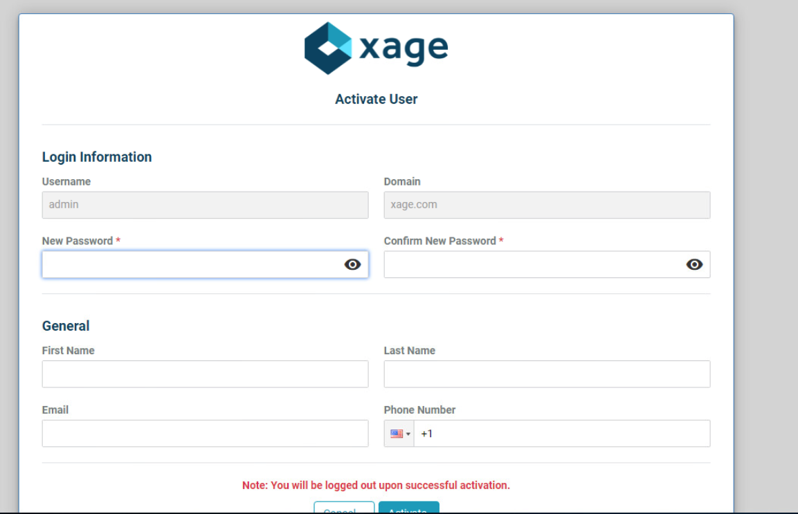
After deployment is finished, you will have to login again and change your password to activate the manager.
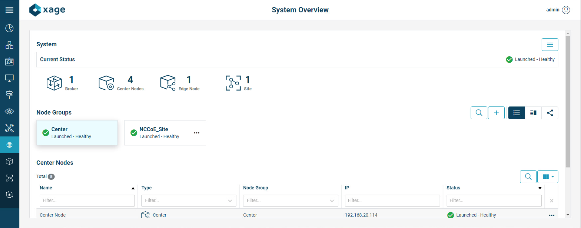
Once logged back in, Xage will show a green check mark labeled Launched – Healthy.
We configured three identities and two devices in the Xage Security Fabric using the Xage manager:
One device was configured for each solar array at UMD.
Three identities were configured:
One identity was given access to both UMD solar arrays.
One identity was given access to only one UMD solar array.
One identity was given no access to the UMD solar arrays.
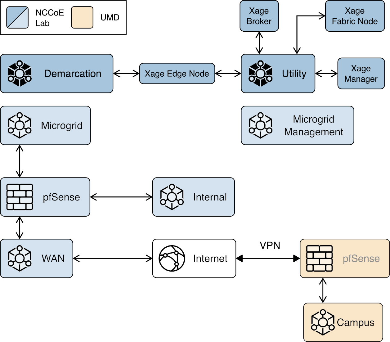
Figure 2‑9 shows the location of the Xage components in the example solution.
Figure 2‑9 Xage Location in the Example Solution
2.8.2 Configure Xage Devices
Follow these steps to configure Xage devices:
From the main Xage System Overview page, select Devices > Devices to create new devices for Xage.
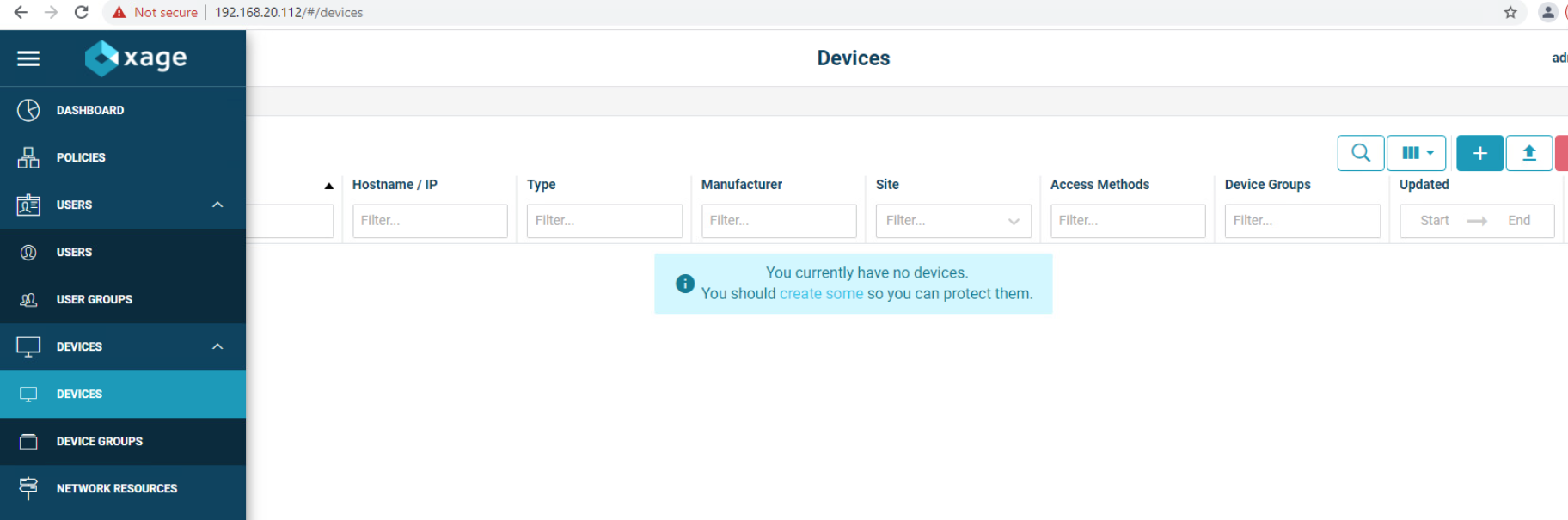
Click the + to create a new device, then fill in the details for that device.
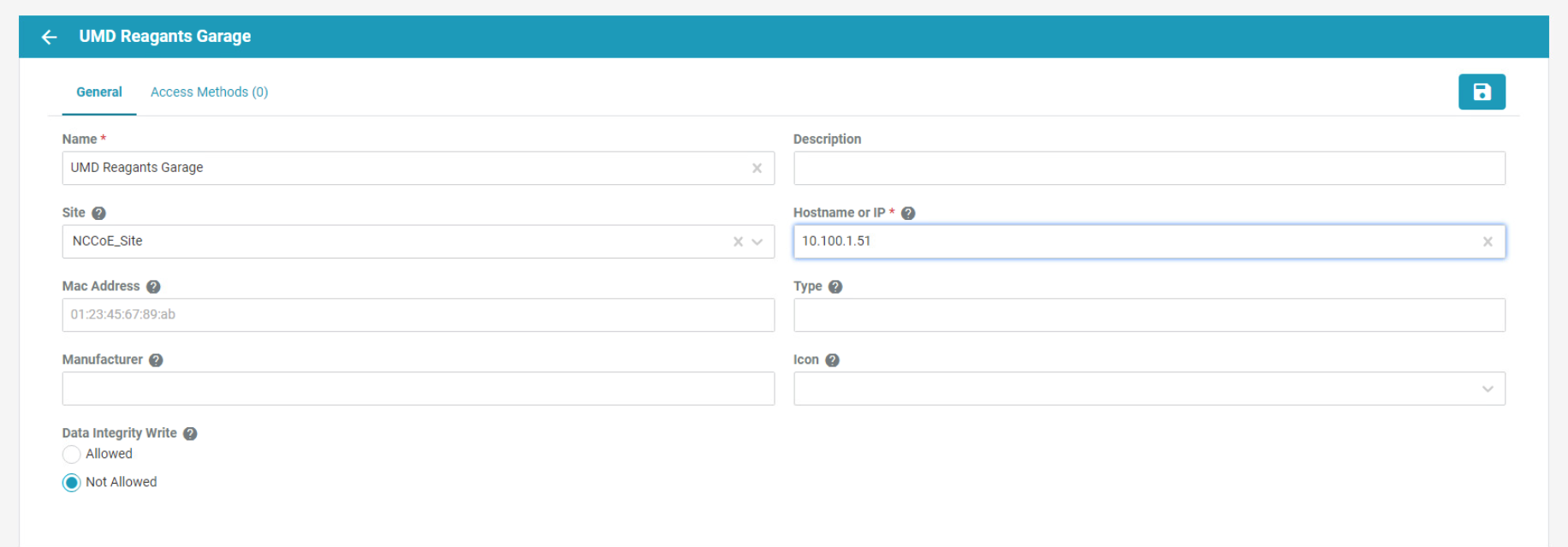
Click the Access Methods tab and fill in the details for an HTTP Proxy. Then click the Create button.
Repeat this method for the second device.
2.8.3 Configure Xage Identities
Follow these steps to configure Xage identities:
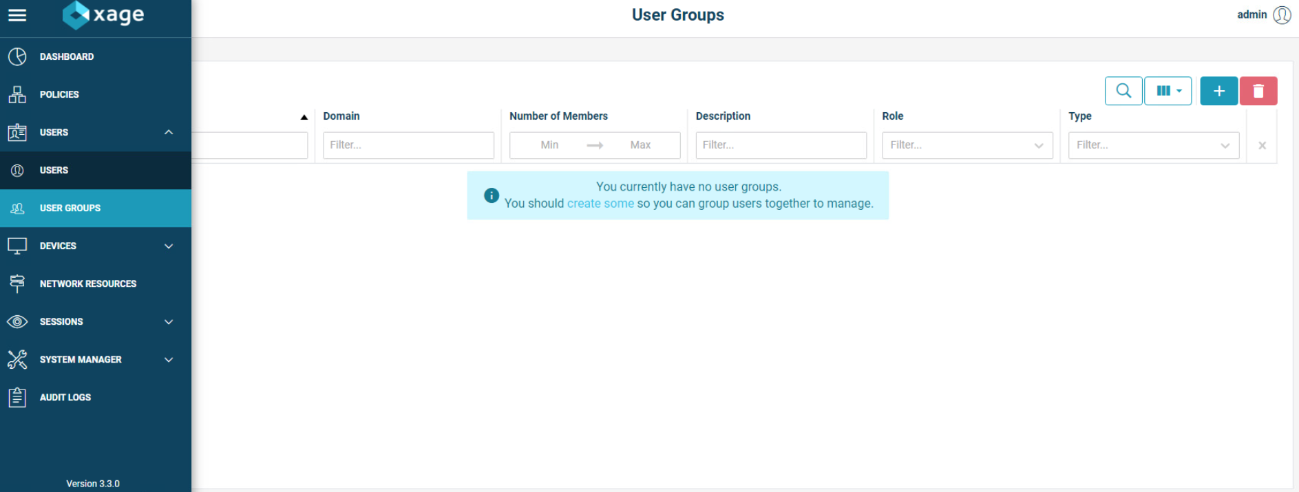
From the main Xage System Overview page, select Users > Users to create new identities for Xage.
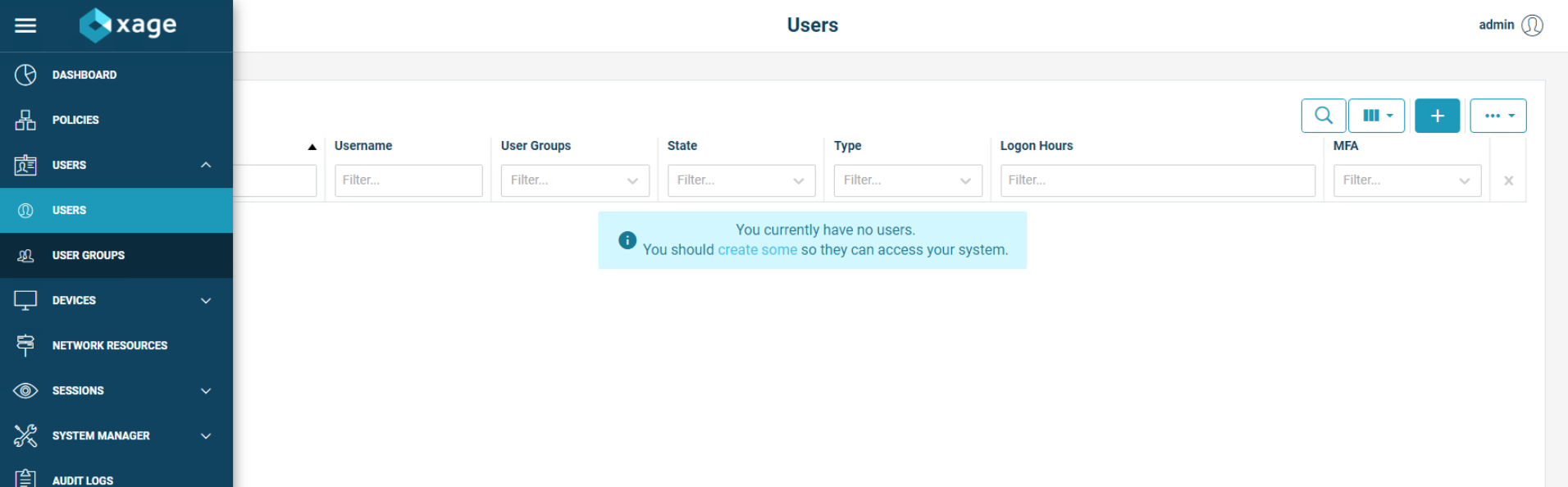
Click the + to create a new user, then fill in the details for that user. This example shows a user that does not use session recording and does not restrict logon hours. The user also does not use multi-factor authentication. When finished, click the Create button.
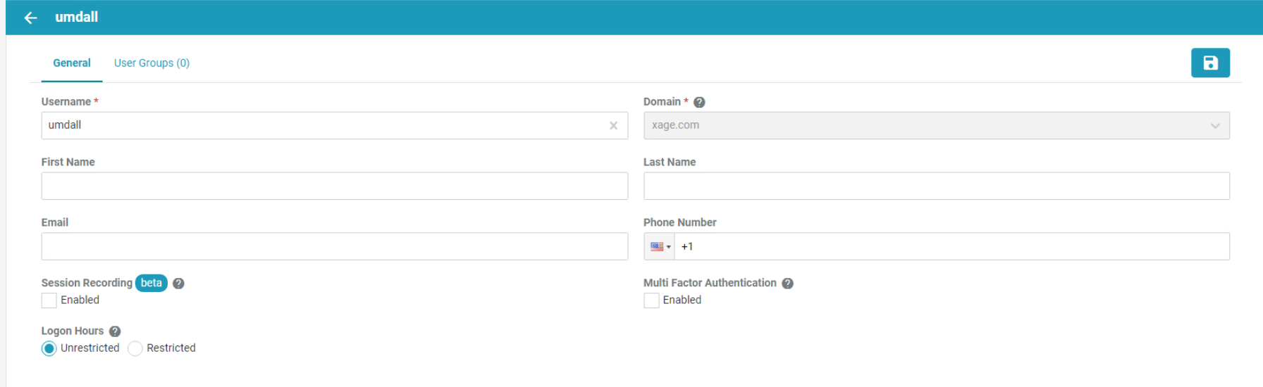
Add in other users as needed.
The next step is to create user groups for the users. Go to Users > User Groups and click the + sign.
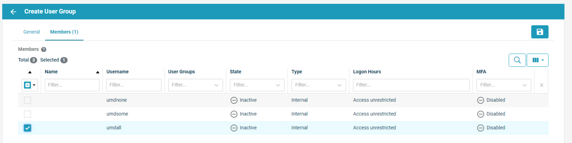
Add in details for the General tab, then move to the Members tab.
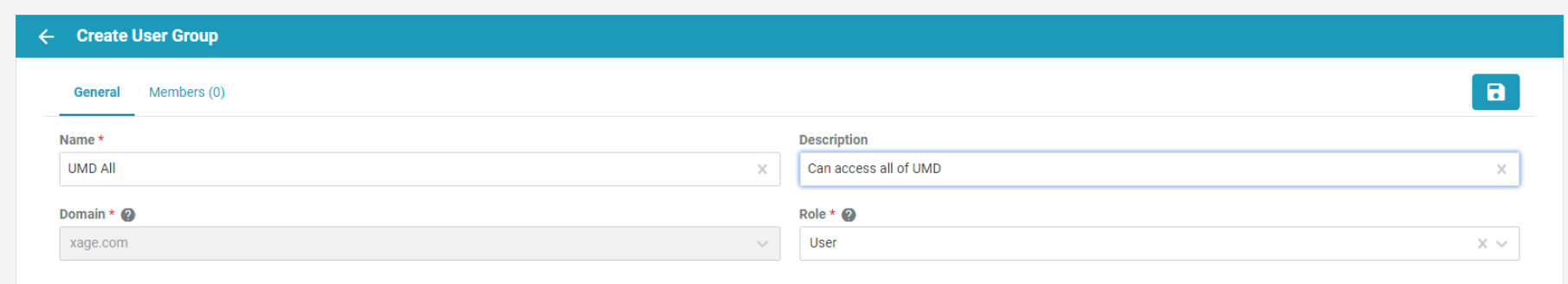
Select users for addition to the current group, then click the Create button. Repeat for all necessary groups.
2.9 pfSense Open-source Firewall
pfSense is an open-source firewall/router used to create a site-to-site VPN tunnel between the NCCoE lab and the UMD campus network.
We installed pfSense using the installation guide at https://docs.netgate.com/pfsense/en/latest/install/download-installer-image.html. We installed pfSense in a Linux virtual machine in our virtual lab using the ISO installation media option.
We used the instructions at https://docs.netgate.com/pfsense/en/latest/vpn/openvpn/index.html to configure the VPN.
2.10 Syslog-ng Open-Source Log Management
Syslog-ng is an open source log server (https://github.com/syslog-ng/syslog-ng). Syslog ng provides the second part of the log collector component of the reference architecture. Syslog ng serves as a syslog aggregator. Cisco ISE and Cisco Cyber Vision send their syslog data to syslog ng. Syslog ng then sends the aggregated data to the Sumo Logic syslog collector for transport to the Sumo Logic software-as-a-service analysis and visualization capabilities to process. Figure 8 shows syslog-ng implementing the reference architecture log aggregator element.
We used Linux Centos 8 VMs to host our syslog-ng instances -ng.
2.10.1 Installing Syslog-ng
Follow these steps to install Syslog-ng:
On a VM that will host syslog-ng, run the command
sudo apt-get install syslog-ng -y.When this completes, check the syslog-ng version with the command
syslog-ng –version.Verify syslog-ng is running with the command
syslog-ngstatus.
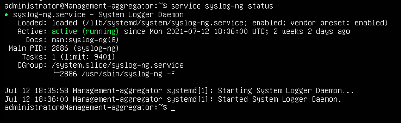
Figure 2‑10 shows the location of the syslog-ng log aggregators in the example solution.
Figure 2‑10 syslog-ng Location in the Example Solution
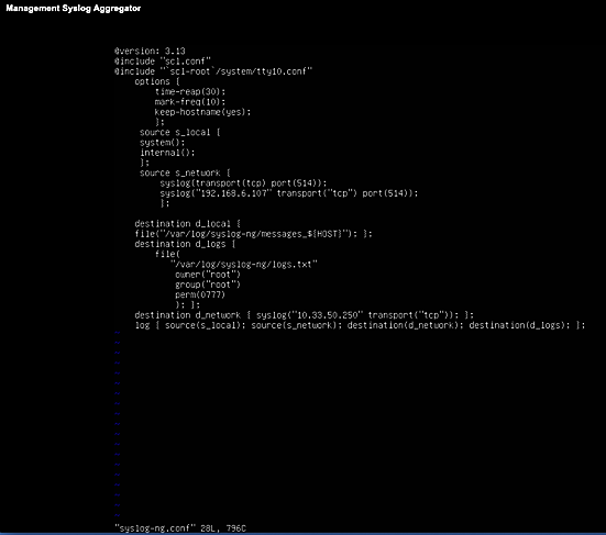
2.10.2 Configuring Syslog-ng
Follow these steps to configure Syslog-ng:
Navigate to the
/etc/syslog-ngdirectory using the commandcd /etc/syslog-ngand run the commandvim syslog-ng.confto configurescl.conf.For each product that sends log data to syslog-ng, edit the source and destination configuration information to add the IP address, protocol, and port number.