NIST SPECIAL PUBLICATION 1800-34C
Validating the Integrity of Computing Devices
Volume C:
How-to Guides
Tyler Diamond*
Nakia Grayson
William T. Polk
Andrew Regenscheid
Murugiah Souppaya
National Institute of Standards and Technology
Information Technology Laboratory
Christopher Brown
Chelsea Deane
Jason Hulburt
The MITRE Corporation
McLean, Virginia
Karen Scarfone
Scarfone Cybersecurity
Clifton, Virgina
* Former employee; all work for this publication was done while at employer
December 2022
FINAL
This publication is available free of charge from https://doi.org/10.6028/NIST.SP.1800-34

DISCLAIMER
Certain commercial entities, equipment, products, or materials may be identified by name or company logo or other insignia in order to acknowledge their participation in this collaboration or to describe an experimental procedure or concept adequately. Such identification is not intended to imply special status or relationship with NIST or recommendation or endorsement by NIST or NCCoE; neither is it intended to imply that the entities, equipment, products, or materials are necessarily the best available for the purpose.
While NIST and the NCCoE address goals of improving management of cybersecurity and privacy risk through outreach and application of standards and best practices, it is the stakeholder’s responsibility to fully perform a risk assessment to include the current threat, vulnerabilities, likelihood of a compromise, and the impact should the threat be realized before adopting cybersecurity measures such as this recommendation.
National Institute of Standards and Technology Special Publication 1800-34C, Natl. Inst. Stand. Technol. Spec. Publ. 1800-34C, 141 pages, (December 2022), CODEN: NSPUE2
FEEDBACK
As a private-public partnership, we are always seeking feedback on our practice guides. We are particularly interested in seeing how businesses apply NCCoE reference designs in the real world. If you have implemented the reference design, or have questions about applying it in your environment, please email us at supplychain-nccoe@nist.gov.
All comments are subject to release under the Freedom of Information Act.
NATIONAL CYBERSECURITY CENTER OF EXCELLENCE
The National Cybersecurity Center of Excellence (NCCoE), a part of the National Institute of Standards and Technology (NIST), is a collaborative hub where industry organizations, government agencies, and academic institutions work together to address businesses’ most pressing cybersecurity issues. This public-private partnership enables the creation of practical cybersecurity solutions for specific industries, as well as for broad, cross-sector technology challenges. Through consortia under Cooperative Research and Development Agreements (CRADAs), including technology partners—from Fortune 50 market leaders to smaller companies specializing in information technology security—the NCCoE applies standards and best practices to develop modular, adaptable example cybersecurity solutions using commercially available technology. The NCCoE documents these example solutions in the NIST Special Publication 1800 series, which maps capabilities to the NIST Cybersecurity Framework and details the steps needed for another entity to re-create the example solution. The NCCoE was established in 2012 by NIST in partnership with the State of Maryland and Montgomery County, Maryland.
NIST CYBERSECURITY PRACTICE GUIDES
NIST Cybersecurity Practice Guides (Special Publication 1800 series) target specific cybersecurity challenges in the public and private sectors. They are practical, user-friendly guides that facilitate the adoption of standards-based approaches to cybersecurity. They show members of the information security community how to implement example solutions that help them align with relevant standards and best practices, and provide users with the materials lists, configuration files, and other information they need to implement a similar approach.
The documents in this series describe example implementations of cybersecurity practices that businesses and other organizations may voluntarily adopt. These documents do not describe regulations or mandatory practices, nor do they carry statutory authority.
ABSTRACT
Organizations are increasingly at risk of cyber supply chain compromise, whether intentional or unintentional. Cyber supply chain risks include counterfeiting, unauthorized production, tampering, theft, and insertion of unexpected software and hardware. Managing these risks requires ensuring the integrity of the cyber supply chain and its products and services. This project demonstrates how organizations can verify that the internal components of the computing devices they acquire, whether laptops or servers, are genuine and have not been tampered with. This solution relies on device vendors storing information within each device, and organizations using a combination of commercial off-the-shelf and open-source tools that work together to validate the stored information. This NIST Cybersecurity Practice Guide describes the work performed to build and test the full solution.
KEYWORDS
Computing devices; cyber supply chain; cyber supply chain risk management (C-SCRM); hardware root of trust; integrity; provenance; supply chain; tampering.
ACKNOWLEDGMENTS
We are grateful to the following individuals for their generous contributions of expertise and time.
Name |
Organization |
|---|---|
Themistocles Chronis |
Archer |
Dan Carayiannis |
Archer |
Jon Amis |
Dell Technologies |
Charles Robison |
Dell Technologies |
Mukund Khatri |
Dell Technologies |
Rick Martinez |
Dell Technologies |
Daniel Carroll |
Dell Technologies |
Jason Young |
Dell Technologies |
Travis Raines |
Eclypsium |
John Loucaides |
Eclypsium |
Jason Cohen |
Hewlett Packard Enterprise |
CJ Coppersmith |
Hewlett Packard Enterprise |
Ludovic Jacquin |
Hewlett Packard Enterprise |
Boris Balacheff |
HP Inc. |
Jeff Jeansonne |
HP Inc. |
Joshua Schiffman |
HP Inc. |
Harmeet Singh |
IBM |
Tom Dodson |
Intel |
Jason Ajmo |
The MITRE Corporation |
Chelsea Deane |
The MITRE Corporation |
Spike E. Dog |
The MITRE Corporation |
Joe Sain |
The MITRE Corporation |
Thomas Walters |
The MITRE Corporation |
Andrew Medak |
National Security Agency (NSA) |
Lawrence Reinert |
NSA |
Manuel Offenberg |
Seagate |
David Kaiser |
Seagate |
Paul Gatten |
Seagate |
Simon Phatigaraphong |
Seagate |
Bill Downer |
Seagate Government Solutions |
Jack Fabian |
Seagate Government Solutions |
The Technology Partners/Collaborators who participated in this build submitted their capabilities in response to a notice in the Federal Register. Respondents with relevant capabilities or product components were invited to sign a Cooperative Research and Development Agreement (CRADA) with NIST, allowing them to participate in a consortium to build this example solution. We worked with:
Technology Partner/Collaborator |
Build Involvement |
|---|---|
Archer Suite 6.9 |
|
PowerEdge R650, Secured Component Verification tool; Precision 3530, CSG Secured Component Verification tool |
|
Eclypsium Analytics Service, Eclypsium Device Scanner |
|
(2) Elitebook 840 G7, HP Sure Start, HP Sure Recover, Sure Admin, HP Client Management Script Library (CMSL), HP Tamperlock |
|
Proliant DL360 Gen 10, Platform Certificate Verification Tool (PCVT) |
|
QRadar SIEM |
|
HP Inc. Elitebook 360 830 G5, Lenovo ThinkPad T480, Transparent Supply Chain Tools, Key Generation Facility, Cloud Based Storage, TSCVerify and AutoVerify software tools |
|
Host Integrity at Runtime and Start-Up (HIRS), Subject Matter Expertise |
|
(3) 18TB Exos X18 hard drives, 2U12 Enclosure, Firmware Attestation API, Secure Device Authentication API |
DOCUMENT CONVENTIONS
The terms “shall” and “shall not” indicate requirements to be followed strictly to conform to the publication and from which no deviation is permitted. The terms “should” and “should not” indicate that among several possibilities, one is recommended as particularly suitable without mentioning or excluding others, or that a certain course of action is preferred but not necessarily required, or that (in the negative form) a certain possibility or course of action is discouraged but not prohibited. The terms “may” and “need not” indicate a course of action permissible within the limits of the publication. The terms “can” and “cannot” indicate a possibility and capability, whether material, physical, or causal.
PATENT DISCLOSURE NOTICE
NOTICE: The Information Technology Laboratory (ITL) has requested that holders of patent claims whose use may be required for compliance with the guidance or requirements of this publication disclose such patent claims to ITL. However, holders of patents are not obligated to respond to ITL calls for patents and ITL has not undertaken a patent search in order to identify which, if any, patents may apply to this publication.
As of the date of publication and following call(s) for the identification of patent claims whose use may be required for compliance with the guidance or requirements of this publication, no such patent claims have been identified to ITL.
No representation is made or implied by ITL that licenses are not required to avoid patent infringement in the use of this publication.
List of Figures
Figure 1‑1 Demonstration Network Architecture
Figure 3‑1 Archer Solution Menu
Figure 3‑2 Enterprise Computing Devices Listing
Figure 3‑3 Asset Inventory Screenshot
Figure 3‑4 Eclypsium Acceptance Testing Firmware Data
Figure 3‑5 Out of Policy Computing Device
Figure 3‑6 Dashboard with No Integrity Issues Detected
Figure 3‑7 Dashboard with Integrity Issues Detected
Figure 3‑8 HP Inc. Laptop Continuous Monitoring
Figure 3‑9 New Security Incident
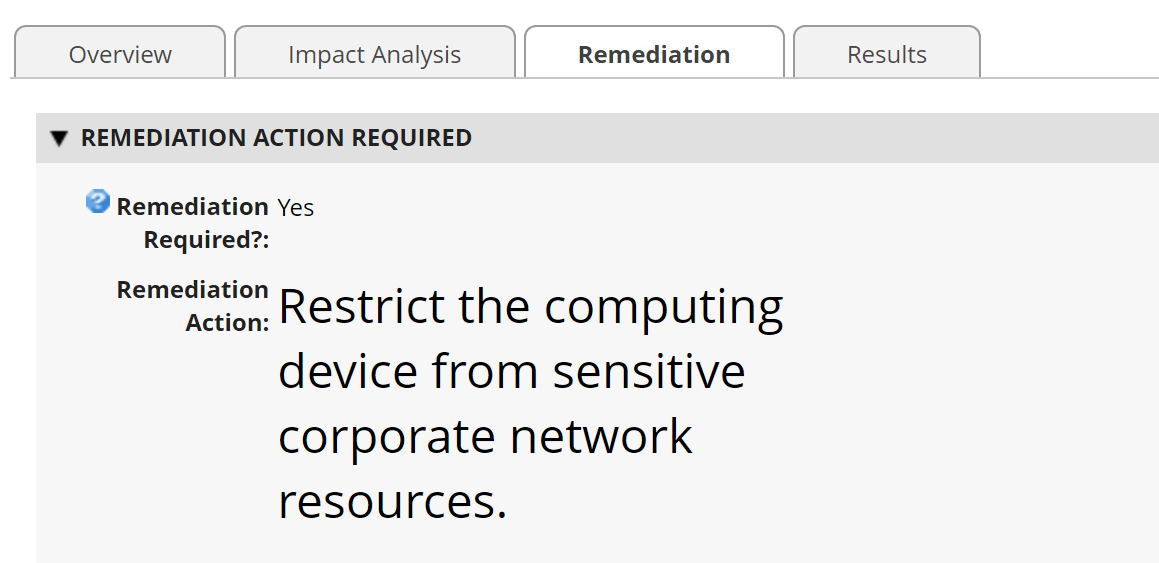
Figure 3‑12 Incident Remediation Action
List of Tables
Table 2‑1 DHCP Proxy System Information
Table 2‑2 HIRS-ACA System Information
Table 2‑3 Intel-Contributed Laptops
Table 2‑4 Intel-Contributed Server
Table 2‑5 Archer IRM System Information
Table 2‑6 Seagate Hardware Contribution
Table 2‑7 Security Incidents Application Custom Data Fields
Table 2‑8 PMCS Data Feed Source Field to Destination Field Mapping
Table 2‑9 QRadar Data Feed Source Field to Destination Field Mapping
Table 2‑10 Seagate Drive Data Feed Field Mapping
Table 2‑11 QRadar Security Event Mapping
Table 3‑2 Calculated Fields (Devices)
Table 3‑3 Components Application
Table 3‑4 HP UEFI Configuration Variables Application
Table 3‑5 Calculated Fields (HP UEFI Configuration Variables)
Table 3‑6 Seagate Firmware Attestation Application
Table 3‑7 Seagate Firmware Hash Application
Table 3‑8 Calculated Fields (Seagate Firmware Hash)
1 Introduction
The following volumes of this guide show information technology (IT) professionals and security engineers how we implemented this example solution. We cover all of the products employed in this reference design. We do not re-create the product manufacturers’ documentation, which is presumed to be widely available. Rather, these volumes show how we incorporated the products together in our environment.
Note: These are not comprehensive tutorials. There are many possible service and security configurations for these products that are out of scope for this reference design.
1.1 How to Use This Guide
This National Institute of Standards and Technology (NIST) Cybersecurity Practice Guide demonstrates a standards-based reference design and provides users with the information they need to replicate verifying that the internal components of the computing devices they acquire are genuine and have not been tampered with. This reference design is modular and can be deployed in whole or in part.
This guide contains three volumes:
NIST Special Publication (SP) 1800-34A: Executive Summary
NIST SP 1800-34B: Approach, Architecture, and Security Characteristics – what we built and why
NIST SP 1800-34C: How-To Guides – instructions for building the example solution (you are here)
Depending on your role in your organization, you might use this guide in different ways:
Business decision makers, including chief security and technology officers, will be interested in the Executive Summary, NIST SP 1800-34A, which describes the following topics:
challenges that enterprises face in decreasing the risk of a compromise to products in their supply chain
example solution built at the NCCoE
benefits of adopting the example solution
Technology or security program managers who are concerned with how to identify, understand, assess, and mitigate risk will be interested in NIST SP 1800-34B, which describes what we did and why. The following sections will be of particular interest:
Section 3.4, Risk, describes the risk analysis we performed.
Section 3.5, Security Control Map, maps the security characteristics of this example solution to cybersecurity standards and best practices.
You might share the Executive Summary, NIST SP 1800-34A, with your leadership team members to help them understand the importance of adopting a standards-based solution for verifying that the internal components of the computing devices they acquire are genuine and have not been tampered with.
IT professionals who want to implement an approach like this will find this whole practice guide useful. You can use this How-To portion of the guide, NIST SP 1800-34C, to replicate all or parts of the build created in our lab. This How-To portion of the guide provides specific product installation, configuration, and integration instructions for implementing the example solution.
This guide assumes that IT professionals have experience implementing security products within the enterprise. While we have used a suite of commercial products to address this challenge, this guide does not endorse these particular products. Your organization can adopt this solution or one that adheres to these guidelines in whole, or you can use this guide as a starting point for tailoring and implementing parts of verifying that the internal components of the computing devices they acquire are genuine and have not been tampered with. Your organization’s security experts should identify the products that will best integrate with your existing tools and IT system infrastructure. We hope that you will seek products that are congruent with applicable standards and best practices. Section 3.6, Technologies, of NIST SP 1800-34B lists the products that we used and maps them to the cybersecurity controls provided by this reference solution.
A NIST Cybersecurity Practice Guide does not describe “the” solution, but a possible solution. Comments, suggestions, and success stories will improve subsequent versions of this guide. Please contribute your thoughts to supplychain-nccoe@nist.gov.
1.1.1 Supplemental Material
Throughout this document there are references to code, scripts, and/or configuration files. Due to the size of some of the files, and to provide a more efficient method of access, we have made these assets available via a NIST GitHub repository. This also enables quicker updates of published code to those interested in replicating parts or all of our demonstration.
1.2 Build Overview
This volume describes the steps necessary to set up an environment that focuses on laptop (sometimes referred to by industry as client) computing devices. It also provides guidance on the operational usage of manufacturers’ tools that may be useful to your IT personnel who verify that the computing device is acceptable to receive into the acquiring organization. This volume also describes validating the integrity of servers and including additional enterprise services as required to support this capability.
1.3 Typographic Conventions
The following table presents typographic conventions used in this volume.
Typeface/ Symbol |
Meaning |
Example |
|---|---|---|
Italics |
file names and path names; references to documents that are not hyperlinks; new terms; and placeholders |
For language use and style guidance, see the NCCoE Style Guide. |
Bold |
names of menus, options, command buttons, and fields |
Choose File > Edit. |
|
command-line input, onscreen computer output, sample code examples, and status codes |
|
Monospace (block)
|
multi-line input, on-screen computer output, sample code examples, status codes |
% mkdir -v nccoe_projects
mkdir: created directory 'nccoe_projects'
|
link to other parts of the document, a web URL, or an email address |
All publications from NIST’s NCCoE are available at https://www.nccoe.nist.gov. |
1.4 Logical Architecture Summary
Figure 1‑1 depicts the architecture for the prototype demonstration environment used within the NCCoE network boundaries. The environment uses a combination of physical and virtual systems to emulate an enterprise architecture. We recommend the reader start with Volume B, Section 4 of this publication for a component-level view of the completed architecture before implementing the systems in this section.
Common enterprise services, such as Active Directory (AD) and Domain Name System (DNS), are provided by NCCoE’s Trusted Enterprise Infrastructure (TEI). TEI provides common services that labs can use. Previously each lab would spend time and resources to set up common services at the beginning of each project and tear them down after the end of the project. To provide efficiency and consistency across projects, and to represent a true enterprise infrastructure, NCCoE has initiated the TEI effort, which offers common services such as core services and shared security services for those labs who would like to use them.
Figure 1‑1 Demonstration Network Architecture
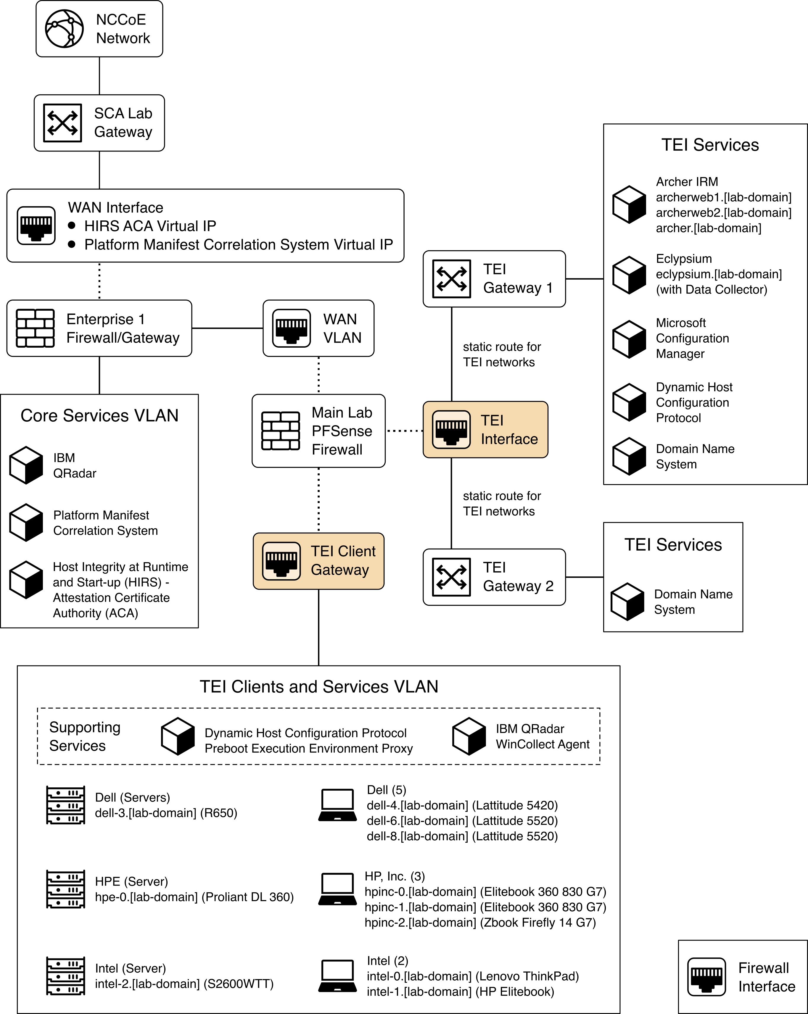
Services specific to the capabilities of this prototype demonstration are instantiated on the Core Services virtual network. This virtual network represents the integration of supply chain risk management (SCRM) requirements into an enterprise architecture to support the SCRM controls, as described in the Risk Assessment section of Volume B.
2 Product Installation Guides
This section of the practice guide contains detailed instructions for installing and configuring all of the products used to build an instance of the example solution.
2.1 Supporting Systems and Infrastructure
This section describes the supporting infrastructure required to execute the acceptance testing and continuous monitoring capabilities provided by our collaborators.
2.1.1 Network Boot Services
The following procedures will create an environment that will enable the acceptance testing of computing devices into an enterprise. First, we create CentOS 7, CentOS 8, and WinPE images that will be booted on computing devices via a Preboot Execution Environment (PXE). We then configure the PXE environment to boot the images.
2.1.1.1 Linux-Based Acceptance Testing Image Creation
On a development CentOS 7 system, install the latest version of the Host Integrity at Runtime and Start-Up (HIRS) Trusted Platform Module (TPM) Provisioner. We’ll use the system as a basis to create the network booted image. Note that there are a number of dependencies that you’ll need to satisfy before installing the HIRS TPM Provisioner package. One of those dependencies, PACCOR, is maintained by the HIRS project. In our prototype demonstration, we used version 1.1.4 revision 5 but recommend using the latest version available. Note that any version prior to revision 5 will not successfully complete the provisioning process with the laptop computing devices used in this demonstration.
2.1.1.1.1 HIRS TPM Provisioner Configuration
The HIRS TPM provisioner is the core application in the computing device acceptance testing process. The system running the provisioner must be configured for your local environment before use.
Use a text editor to configure the HIRS TPM Provisioner for your local environment.
$ [your favorite editor] /etc/hirs/hirs-site.configChange the variables noted below and save the file.
#******************************************\*
#\* HIRS site configuration properties file
#******************************************\*

# Client configuration
CLIENT_HOSTNAME=localhost
TPM_ENABLED=true
IMA_ENABLED=false

# Site-specific configuration
ATTESTATION_CA_FQDN=hirs-server.yourdomain.test
ATTESTATION_CA_PORT=8443
BROKER_FQDN=hirs-server.yourdomain.test
# Change this port number to your local configuration
BROKER_PORT=61616
PORTAL_FQDN=hirs-server.yourdomain.test
# Change this port number to your local configuration
PORTAL_PORT=8443
If using a network boot environment, use the configuration file (step 2) in the kickstart file that creates the CentOS 7 provisioner image in the
%postsection.
2.1.1.1.2 Eclypsium Agent Configuration
On the same CentOS 7 system described in Section 2.1.1.1.1, install the Eclypsium Linux agent using the following procedures.
Navigate to the Eclypsium Management Console in a web browser.
Select Deployment > Download.
Download the Linux (RPM) Portable Scanner. The filename will have the format
eclypsium_agent_builder-x.x.x.run.Install the prerequisites for the builder script.
# yum groupinstall "Development Tools"

# yum install kernel-devel
Run the builder script downloaded above as a user with root privileges. This will build the Eclypsium Portable Scanner drivers, extract the application binaries, and place them into a directory named
eclypsium_agent.# ./eclypsium_agent_builder-X.X.X.run –out [PATH]Confirm the previous step was successful by listing the
eclypsium_agentdirectory and ensuring the portable scanner was created with the nameEclypsiumAppPortable. This executable is referenced by our customized acceptance testing script.
2.1.1.1.3 CentOS 7 Image Creation
The CentOS 7 image we created enables quick revisions and simultaneous measurements on our devices. The image runs the required kernel, configures the system for reaching our infrastructure, and includes vendor tools to perform platform measurements. In order to generate the CentOS 7 image, the livecd-creator tool is utilized on a separate CentOS 7-based system. This tool uses Anaconda, Kickstart, and Lorax to generate the image. The following steps are performed:
Install the latest livecd-tools package, preferably built directly from the project GitHub repository.
Create your own kickstart file or use the kickstart that will be provided by this project as a basis for your own. In our kickstart, we will insert commands to install required dependencies of our vendor products. Your environment will require further configuration to include networking, host file modification, and user management. You will also need to adjust hostnames and IP addresses to fit your environment.
Some tools, such as required drivers, were installed into a local repository (repo) on the image generating system using the
createrepocommand. This repo can be accessed by kickstart during the image generation. Copy HIRS_Provisioner_TPM_2_0-X.X.X.x86_64.rpm and paccor-X.X.X-X.noarch.rpm into the newly created repository.$ createrepo -u file:///sca-packages sca-packagesGenerate the ISO image from the kickstart file.
$ livecd-creator –-config=kickstart-filename.ksThe ISO file will be created in the local directory with a filename indicating the time of generation. Once this is done, the pxeboot directory can be generated:
$ livecd-iso-to-pxeboot imagename.isoThe pxeboot directory will be created, containing the required vmlinuz and initrd0.img files. It will also create a directory named pxelinux.cfg which contains a file named default. default contains the kernel flags necessary to boot the image. Use these files in the PXE environment detailed in Section 2.1.1.3.
2.1.1.1.4 CentOS 8 Image Creation
Before continuing with CentOS 8 image creation, create the prerequisite files in Section 2.6. This set of procedures creates an acceptance testing environment similar to what is described in Section 2.1.1.1.3 with the following deviations:
In Step 2, retrieve the CentOS 8 kickstart file (Integration-Scripts\Acceptance Testing Environment Build Scripts\HPE PCVT - Centos8\HPE - Centos8.ks) from the project repository.
In Step 3, retrieve the latest version of the Java 11 Java Development Kit (JDK). This demonstration uses Azul Zulu build, but other builds may also work. Additionally, create a folder named
HPE
Tooling
in your working directory. Copy the provisioning scripts (Integration-Scripts\Manufacturer-specific Scripts and Tools\HPE Tooling) from our repository into the directory as well as the HPE Platform Certificate Verification Tool (PCVT) binaries built in Section 2.6.Complete the remaining steps as documented.
2.1.1.2 Windows-Based Acceptance Testing Image Creation
The following procedures will produce a Windows Preinstallation Environment (WinPE) bootable image that can be used in computing device acceptance testing. You will need to have a Windows Server (2016 or above) environment available to complete the following steps.
2.1.1.2.1 Build WinPE
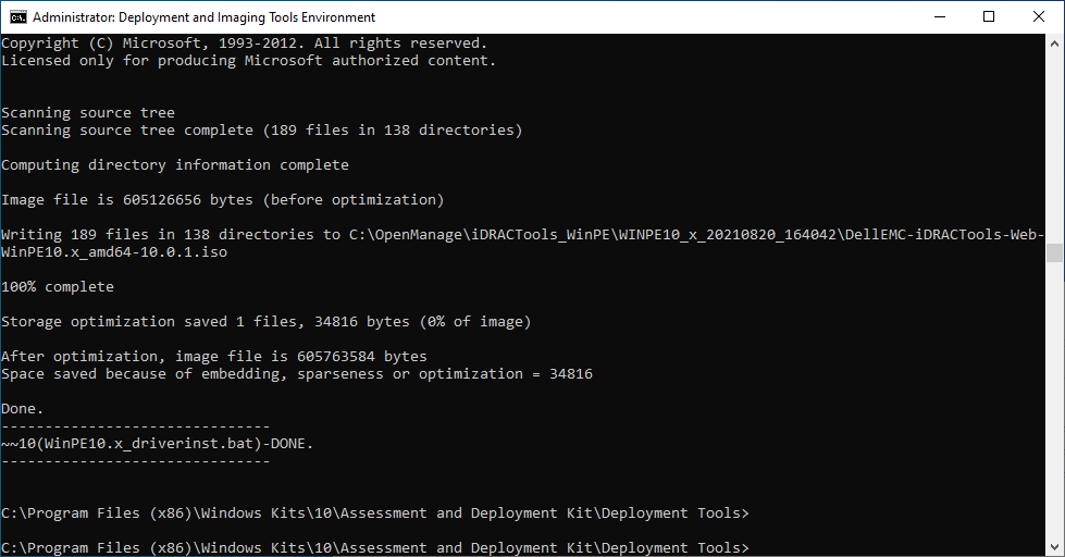
Download and install the Windows Assessment and Deployment Kit (ADK) and WinPE add-on.
Download the Dell EMC iDRAC Tools for Microsoft WinPE (R), v10.1.0.0 software package.
Run the self-extractor and choose all defaults.
Launch cmd.exe as an administrator and change directory to the extracted folder, then run our modified batch file (WinPE10.x_driverinst - ps1.bat).
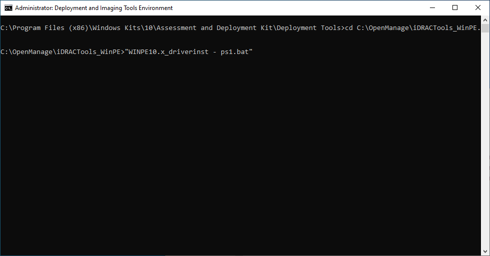
If successful, the preceding batch script will create a folder in the same directory with a name similar to WINPE10.x-%timestamp% or WINPE5.x-%timestamp%.
2.1.1.3 Preboot Execution Environment (PXE)
2.1.1.3.1 Dynamic Host Configuration Protocol (DHCP) Proxy
In this prototype demonstration, we use a combination of DNSMasq and the iPXE project to deliver the acceptance testing capabilities to computing devices. DNSMasq provides network boot services via DHCP on a network that already has other DHCP services present, such as assigning IP addresses to hosts. Since our network used DHCP services that could not easily be modified for network boot, we made the design decision to use DNSMasq as a proxy. However, for your setup you may want to include network boot services directly into the DHCP product that is used in your environment.
The iPXE project provides open-source network boot firmware. Using iPXE enabled a script-based boot process from an HTTP server. We also chainload the iPXE boot process from a Trivial File Transfer Protocol (TFTP) server, avoiding the need to replace the network card firmware with an iPXE client.
The system specification and procedures follow below. Note that this project uses computing devices that support Unified Extensible Firmware Interface (UEFI) booting and does not support legacy personal computer (PC) Basic Input/Output System (BIOS) booting. Table 2‑1 shows the system information used in our prototype demonstration.
Table 2‑1 DHCP Proxy System Information
Operating System |
Version |
Platform |
|---|---|---|
Ubuntu Server |
Release 20.04 |
Virtual Machine |
Install DNSMasq, the TFTP server, and the HTTP server using the software package manager of your chosen operating system (OS). On Ubuntu, use the following command.
$ apt install dnsmasq tftpd-hpa apache2Create a custom iPXE bootloader that directs iPXE to boot from a fixed URL.
Create a file named embed.ipxe with the following contents.
#!ipxe

dhcp

chain http://<IP or Hostname>/ipxe/boot.ipxe || shell
Download and extract the iPXE source files. Install all software dependencies noted on the download page.
Change directory to ipxe/src and run the following command.
$ make bin-x86_64-efi/ipxe.efi EMBED=/path/to/embed.ipxe
Copy the newly built iPXE efi boot file to /var/lib/tftpboot.
Edit the DNSMasq configuration file to suit your environment.
$ [your favorite editor] /etc/dnsmasq.confEnsure the following configuration variables are set in the configuration file:
pxe-service=x86-64_efi,"Network Boot EFI",ipxe.efi

enable-tftp

tftp-root=/var/lib/tftpboot
Restart DNSMasq.
$ systemctl restart dnsmasqCopy the WinPE, CentOS 7, and CentOS 8 images to the HTTP server.
In the root of your HTTP server, create two directories to store the images.
$ mkdir -p images/winpe images/centos7Copy the /media directory created in Section 2.1.1.2.1 to images/winpe.
Copy initrd.img and vmlinuz created in Section 2.1.1.1.2 to images/centos7.
Copy initrd.img and vmlinuz created in Section 2.1.1.1.4 to images/centos8.
Download the latest wimboot binary from the iPXE repository and store it in the images directory.
Create a directory named ipxe in the HTTP server root, and copy the boot.ipxe file supplied by this project’s repository to this location. Consider our configuration file as a starting point and ensure the contents of this file match your environment. Errors may result in a non-functioning network boot service.
2.1.2 Platform Manifest Correlation System (PMCS)
The PMCS is custom software that allows original equipment manufacturer (OEM) platform manifests (post-acceptance testing) to be translated into a format that is suitable for the Asset Discovery and Repository System (Archer Integrated Risk Management [IRM]). The system provides a web user interface (UI) for the IT administrator, and representational state transfer (REST) application programming interfaces (APIs) are provided for programmatic access. The following steps will set up the environment.
The system is based on Node.js, an open-source JavaScript runtime built on Chrome’s V8 JavaScript engine designed to build scalable network applications. Download and install Node.js on a system best suited for your environment. This demonstration uses an Ubuntu 20.04.2 LTS virtual machine.
Install the node package manager (npm).
Install git on the platform chosen in Step 1. Git provides source code management capabilities used in later steps.
Install Process Manager 2 (PM2). This package will manage the Node.js processes that run the PMCS codebase.
$ npm install pm2 -gStart the application using pm2 from the cloned copy of the project repository:
$ cd platform-manifest-collation-system

$ pm2 start index.js
The PMCS should now be running as a background process. Consider using a startup script to keep your process list intact across expected or unexpected machine restarts.
2.2 Dell
2.2.1 Laptops
The following section describes how to prepare Dell laptops for acceptance testing and continuous monitoring scenarios. Note that the Dell Trusted Device agent requires access to the Dell cloud. Consult the Dell website to determine the ports and IP addresses. Additionally, download the custom scripts for the scheduled tasks from our repository and store them on each target Dell laptop. In this demonstration, we chose c:\Dell\HIRS and c:\Dell\TrustedDevice.
2.2.1.1 Extract the Platform Certificate
Perform the following preparatory steps to create an acceptance testing environment suitable for Dell laptops. Contact your Dell representative to ensure the target laptop has been provisioned with a Platform Certificate from the factory.
Boot the target Dell laptop to the Windows 10 environment.
Start cmd.exe as an Administrator and run the following command:
mountvol o: /sCopy o:\EFI\tcg\cert\platform\Dell.[Line of Business].[Servicetag].ver2.Base.cer to a system with a text editor available. Note that Line of Business and Servicetag will be specific to your laptop.
Separate the Platform Certificate from the signing certificate:
Cut the signing certificate out of the file and save the Platform Certificate.
-----BEGIN CERTIFICATE-----<cert content> -----END CERTIFICATE-----

{Ctrl} + X

{Ctrl} + S
Create a new file and save it as the signing certificate.
{Ctrl} + N

{Ctrl} + V

{Ctrl} + S
Name the signing certificate.
<HSM-Signing-Certificate.cer>
Create a dedicated CentOS 7 host for running the HIRS Attestation Certificate Authority (ACA) portal that is accessible to the computing device undergoing acceptance testing. This step is detailed in Section 2.4.
Create a network bootable CentOS 7 image. This step is detailed in Section 2.1.1.
Note that to perform acceptance testing with Dell laptops, two settings in the BIOS are modified:
Power-on the laptop and boot to the BIOS setup by pressing the Function 2 (F2) key.
Clear the TPM to remove Windows ownership of the device. Navigate to Security > TPM 2.0 Security > Clear in the main menu. Click the Clear radio box and select Yes in the dialog box.
Turn off Secure Boot. Navigate Secure Boot > Secure Boot Enable in the main menu. Click the Clear radio box and select Yes in the dialog box.
Reboot the laptop by clicking Apply and Yes in the dialog box followed by Exit.
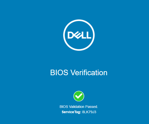
2.2.1.2 Install the Dell Trusted Device Agent
General installation instructions are posted on the Dell website. Below, we use the interactive graphical installation wizard, but other deployment options are also available.
Download the latest version of the Dell Trusted Agent from the Dell website.
Open a command prompt as an Administrator. Install the agent with the following command:
msiexec.exe /i Trusted-Device-<version>\Win64R\TrustedDevice-64bit.msiAn installation wizard will launch. Click Next and then the Install button. The installation package will warn that the laptop will require a reboot. Accept the warning.
Follow the prompt to reboot the laptop. After the reboot, check the installation by manually launching the agent. If successful, a browser window will launch with a message similar to the following.
2.2.1.3 Create the Scheduled Tasks
These procedures will create two tasks that periodically execute our custom scripts, which silently launch the Dell Trusted Device (DTD) agent/HIRS Provisioner Agent and detect platform integrity issues.
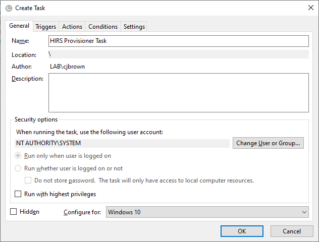
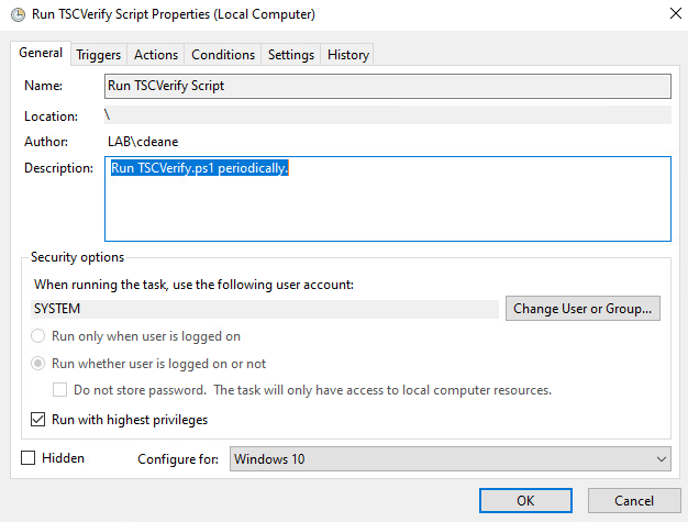
Open the Task Scheduler as an Administrator on the target laptop.
Select Action > Create New Task.
In the General tab, enter a name for the task in the Name field. Click the Change User or Group button and select the System account. Select Windows 10 from the Configure for pull-down menu.
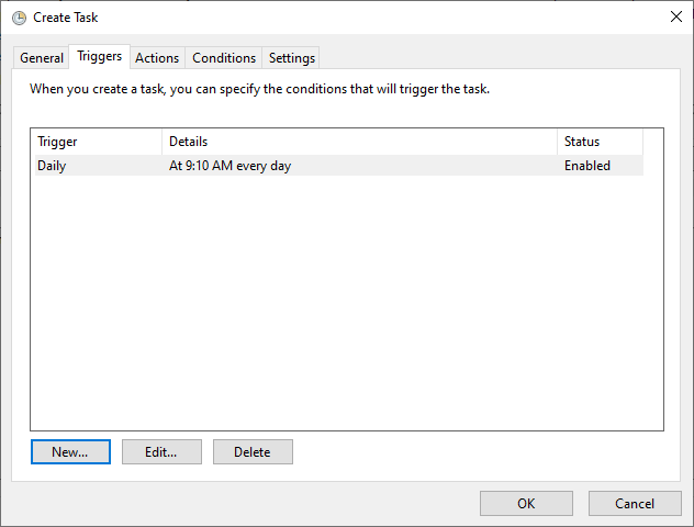
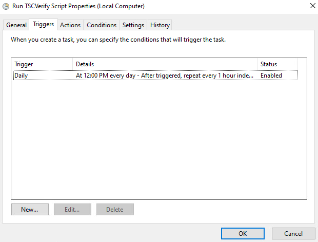
In the Triggers tab, click the New… button. Select a scheduled time appropriate for your environment. Once per day is shown in the example below.
In the Action tab, click the New… button. Enter powershell.exe in the Program/script field. Enter -file “C:\DellHIRS\hirs_script.ps1” in the Add arguments (optional) field. Adjust this value if needed if the custom script is installed in a different location. Click the OK button.
Click the OK button to save the new scheduled task.
Repeat this section to create a scheduled task that will periodically execute the Dell Trusted Device agent using the custom script.
2.2.2 Servers
The Dell R650 used in this demonstration does not require any preparatory activities for acceptance testing. All platform validation tools are included in the network-booted acceptance testing environment. Continue with creating the WinPE acceptance testing environment as described in Section 2.1.1.2.
2.3 Eclypsium
Eclypsium is a firmware security solution with cloud-based and on-premises deployment options. It secures firmware in servers, endpoints, and network devices by:
identifying devices that contain firmware and creating detailed profiles of each component;
verifying these profiles are free of vulnerabilities, have maintained their integrity, and are properly configured; and
fortifying device firmware through a combination of configuration hardening, automated updates, and packaged guidance.
For this demonstration, Eclypsium is leveraged in the acceptance testing and continuous monitoring scenarios. The procedures below will install the Eclypsium agent and continuously monitor Windows-based laptops and Linux-based servers. In the server use case, we configured the agent to communicate with the on-premises deployment of the Eclypsium analytic backend. Refer to Section 3 in NIST SP 1800-31C for installation procedures.
2.3.1 Download Eclypsium Agent
Navigate to the Eclypsium Management Console in a web browser.
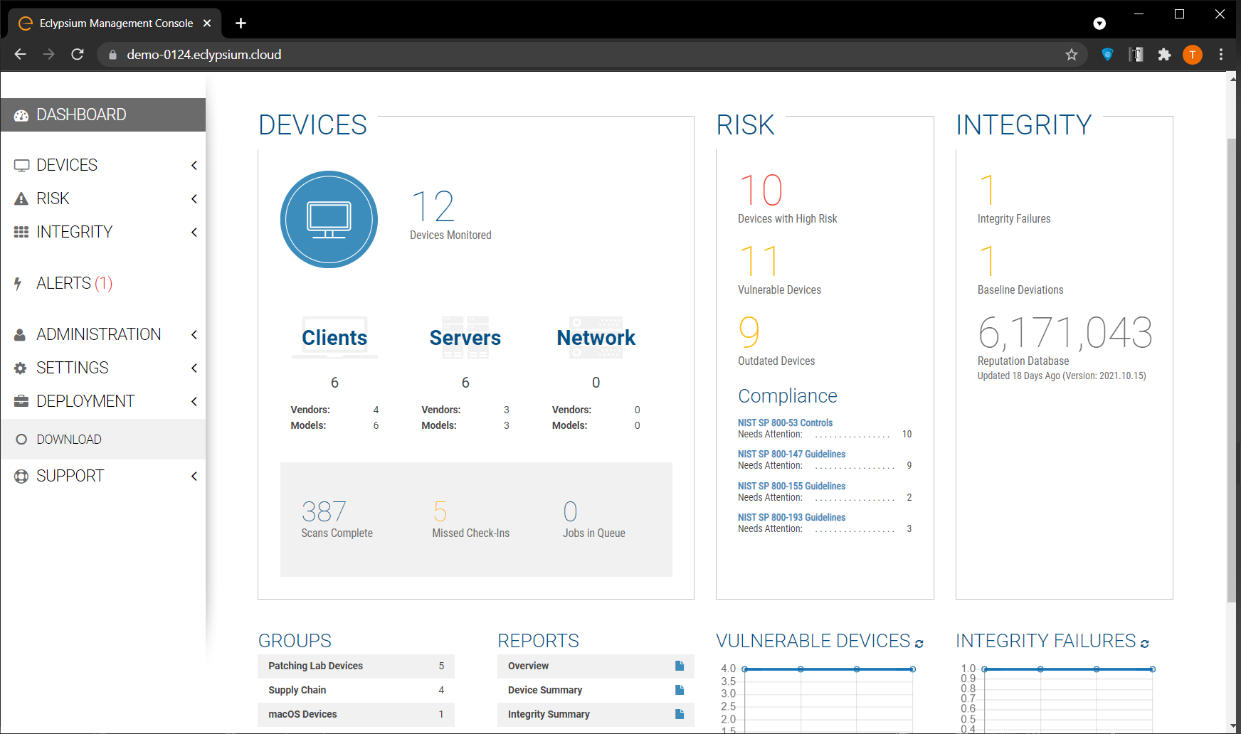
Select Deployment > Download.
Download the installer for the appropriate OS (Windows, macOS, Linux (Deb), or Linux (RPM)).
2.3.2 Install Eclypsium Agent for Windows
Start the Eclypsium bundled installer, Eclypsium-<version>.exe.
Select Next.
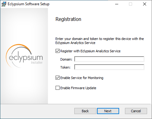
Ensure Register with Eclypsium Analytics Service and Enable Service for Monitoring are selected. Enter the Domain and Registration Token that can be found on the Download page of the Eclypsium Management Console, then select Next.
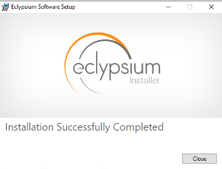
Select Install to start the Eclypsium installation.
When prompted, select Finish.
The Eclypsium agent has successfully installed once the page depicted below is reached. Select Close.
When the system scan completes on a newly installed system, the Eclypsium console will identify supply chain integrity concerns and recommend a resolution.
2.3.3 Install Eclypsium Agent for Linux
Ensure the App and Driver installation packages that are appropriate for your distribution are available on the host server system. The example below is an Ubuntu distribution.
Install the packages with the following command with root privileges. Note that there may be prerequisite packages that are required before installing the Eclypsium packages.
dpkg -i eclypsiumapp-2.8.1.deb eclypsiumdriver-2.8.1.debRegister the Eclypsium agent with the on-premises backend with the following command with root privileges.
EclypsiumApp -s2 <Eclypsium-backend-hostname> reg_<token>
If successful, the server is registered and an initial scan is performed. The output should be similar to the following.
Scan data dumped to
'/home/<user>/<hostname>-21ee761e90f38bb0-2022-05-09T12_26_27Z.tar.gz'

Basic info updated successfully. Check the device at
https://<backend-hostname>/resolve-job/6279087374e1ae0726c3d68f

Successful registration.

[Dumping system firmware through SPI] \\ 16777KB

[Dumping system firmware through MMIO] / 16777KB

[Uploaded 100%] [##############################] 12999KB/12999KB

Scan data dumped to
'/home/<user>/<hostname>-21ee761e90f38bb0-2022-05-09T12_26_27Z.tar.gz'

Scan data updated successfully. Check the device at
<backend-hostname>/resolve-job/627908e374e1ae3a06c3d800
2.4 Host Integrity at Runtime and Start-Up (HIRS) Attestation Certificate Authority (ACA)
This section describes the installation and configuration of the HIRS-ACA backend components used in the acceptance testing scenario. HIRS-ACA is an open-source tool with three components that are used in this demonstration – the Attestation Certificate Authority, dashboard, and provisioner. The ACA issues identity credentials to devices that have a TPM 2.0 security module; these credentials are requested by the provisioner software. The HIRS-ACA dashboard is available to administrators to view and configure validation reports, credentials, and certificate trust chains. Table 2‑2 shows the system information used in our prototype demonstration.
Table 2‑2 HIRS-ACA System Information
Operating System |
Version |
Platform |
|---|---|---|
Centos |
7 |
Virtual Machine |
2.4.1 Installing the HIRS-ACA
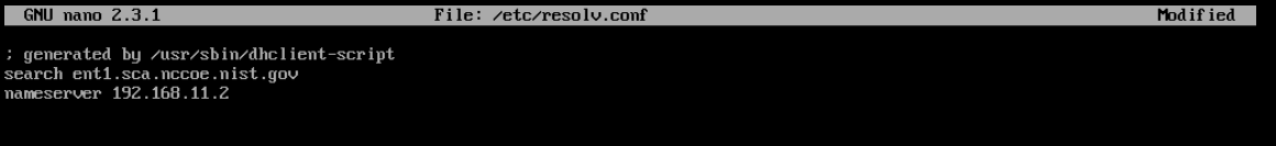
Before installing the required packages, ensure the target system has a fully qualified distinguished hostname. Modify the /etc/hosts, /etc/hostname, and /etc/resolv.conf system configuration files as appropriate.


Install the HIRS-ACA dependencies using the following command. This will install MySQL/MariaDB, OpenSSL, Tomcat, Java, RPM Dev Tools, GNU Core Utilities, and other Linux commands (initscripts, chkconfig, sed, grep, firewalld, and policycoreutils).
# sudo yum install mariadb-server openssl tomcat java-1.8.0
rpmdevtools coreutils initscripts chkconfig sed grep firewalld
policycoreutils
Download the latest version of HIRS ACA from the Release page on GitHub and execute the following command to install the HIRS ACA.
# sudo yum install HIRS_AttestationCA*.rpm
Ensure the installation was successful by navigating to the dashboard using the fully qualified domain name (FQDN) configured above. It should look like the screenshot below.
2.5 HP Inc.
The following steps install the HP Client Management Script Library (CMSL) and execute prerequisite provisioning for HP Inc. laptops. The CMSL installs several PowerShell commands on the laptop that will assist in platform validation. Once CMSL is installed, an administrator configures the HP Inc. specific device security feature. In this prototype demonstration, the target computing devices were an HP Inc. Elitebook 840 G7 and Zbook Firefly 14 G7.
2.5.1 Install the HP CMSL
Download the latest CSML from the HP Developers website onto the target HP Inc. laptop.
Launch the executable file and proceed through the wizard. Accept the agreement and click Next.
Select Install into PowerShell path and click Next.
Click Install.
Click Finish.
Test the installation by opening PowerShell as an administrator and executing a CMSL command such as
Get-HPBIOSVersion.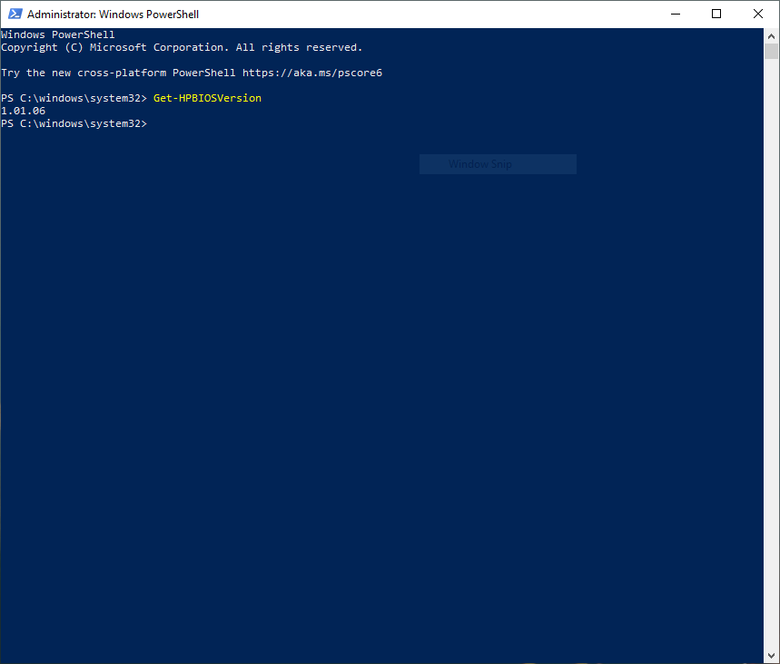
2.5.2 Execute Provisioning Steps
The next steps are used to provision the HP Inc. specific firmware and device security features, HP Sure Start, HP Sure Admin, HP Tamperlock, and HP Sure Recover. Implementers may also want to consult the HP Inc. Developers Blog for more information on how these payloads were created. Using the example provisioning payloads available from our project repository, use the CMSL to apply the six provisioning payloads as shown below:
Open PowerShell as an administrative user. Execute the following commands.
Set-HPSecurePlatformPayload -PayloadFile EKProvisionPayload.dat

Set-HPSecurePlatformPayload -PayloadFile SKProvisionPayload.dat
Reboot the laptop. A local administrator must accept the Physical Presence Prompt to complete provisioning of the Endorsement and Signing Key.
Execute the following commands from PowerShell as an administrator.
Set-HPSecurePlatformPayload -PayloadFile EnableEBAMPayload.dat

Set-HPSecurePlatformPayload -PayloadFile LAKProvisionPayload.dat
Reboot the laptop. This will expose settings that require a BIOS administrator be configured before the next step can be completed.
Execute the following commands from PowerShell as an administrator.
Set-HPSecurePlatformPayload -PayloadFile BIOSsettingsPayloadFile.dat

Set-HPSecurePlatformPayload -PayloadFile SureRecoverProvision.dat
2.6 Hewlett Packard Enterprise (HPE)
We demonstrate HPE’s Platform Certificate Verification Tool (PCVT) in this project by creating a network bootable acceptance testing environment which has PCVT tools and dependencies pre-installed on the image. This image also includes a bash script which executes the PCVT command and, if successful, uploads the hardware manifest to the PMCS.
First, compile the PCVT tools on a separate CentOS 8 system. The general procedures are on the HPE GitHub site and our specific commands follow.
Download and extract the source code from the HPE repository.
Install the software prerequisites onto the system.
yum -y install systemd-devel golang maven java-11-openjdk java-11-openjdk-develChange directory into the PCVT source code. Run the following command:
mvn install:install-file
-Dfile=/<pcvt_source_directory>/PCVT-pcvt_v1.0.0/lib/HIRS_Utils-1.1.1.jar
-DgroupId=HIRS_Utils -DartifactId=HIRS_Utils -Dversion=1.1.1
-Dpackaging=jar
-DlocalRepositoryPath=/<pcvt_source_directory>/.m2/repository
mvn install:install-file
-Dfile=/<pcvt_source_directory>/PCVT-pcvt_v1.0.0/lib/HIRS_Structs-1.1.1.jar
-DgroupId=HIRS_Structs -DartifactId=HIRS_Structs -Dversion=1.1.1
-Dpackaging=jar
-DlocalRepositoryPath=/<pcvt_source_directory>/.m2/repository
mvn install:install-file
-Dfile=/<pcvt_source_directory>/PCVT-pcvt_v1.0.0/lib/paccor-1.1.3-2.jar
-DgroupId=paccor -DartifactId=paccor -Dversion=1.1.3-2
-Dpackaging=jar
-DlocalRepositoryPath=/<pcvt_source_directory>/.m2/repository
Build the PCVT.
mvn clean compile assembly:singleChange to the diskScan directory.
Set the GOPATH to a local directory and set GO11Module to off.
export GOPATH=$HOME/<local_path>/gowork

go env -w GO111MODULE=off
Execute the build script in the build directory.
./build/create_install_bundle.sh
Ensure two files named pcvt-mvn-0.0.1-jar-with-dependencies.jar and libdiskscan.so are generated. Next, the acceptance testing environment is built. Continue with the procedures documented in Section 2.1.1.1.4.
2.7 Intel
The Intel Transparent Supply Chain (TSC) requires two client applications to support acceptance testing and continuous monitoring scenarios: TSCVerifyUtil and AutoVerifyTool. Contact your Intel representative to download the installation packages for both utilities.
2.7.1 Laptops
Once the binaries have been retrieved, follow these procedures on the target laptop. Table 2‑3 lists the laptops used within this demonstration.
Table 2‑3 Intel-Contributed Laptops
Machine Name |
Operating System |
Manufacturer |
Model |
|---|---|---|---|
intel-0 |
Windows 10 |
HP Inc. |
Elitebook 360 830 G5 |
intel-1 |
Windows 10 |
Lenovo |
ThinkPad T480 |
Download and install the latest Microsoft Visual C++ Redistributable for Visual Studio.
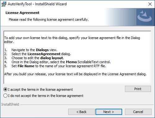
Launch the AutoVerifyTool installation wizard. Click Next.
Accept the license and client Next.
Enter your Name and Organization. Click Next.
Select the Typical installation. Click Next.
Click Install.
2.7.2 Servers
The server contributed by Intel requires the installation of the TSCVerifyUtil application. Contact your Intel representative to determine the best method in your use case. In this prototype implementation, we opted to execute TSCVerifyUtil from a directory created at /opt/intel/tsc. Table 2‑4 lists the server contributed by Intel for this demonstration.
Table 2‑4 Intel-Contributed Server
Machine Name |
Operating System |
Ma nufacturer |
Model |
|---|---|---|---|
intel-2 |
CentOS 8 |
Intel |
S2600WTT Server Board |
Additionally, to complete the implementation we connected the Seagate enclosure to this server board. Refer to Section 2.9 for a description of this process.
2.8 Archer Integrated Risk Management (IRM)
This section describes the installation of the Archer IRM system for this demonstration. Our instantiation of Archer IRM is viable for a lab environment, but the reader is encouraged to refer to the architecture planning guide on the Archer IRM website for specific guidance for your environment. We elected to install the Archer IRM system across two virtual machines—one hosting a Microsoft SQL database and the other hosting the remainder of the Archer IRM services. Note that the screenshots below are from our original installation of Archer IRM 6.9. During the course of the project, we updated our Archer IRM instance to version 6.10. As a result, some screenshots may differ in your implementation from what is presented in this document.
Table 2‑5 shows the system information used in this prototype demonstration for Archer IRM.
Table 2‑5 Archer IRM System Information
Machine Name |
Machine Type |
Operating System |
|---|---|---|
Archer Database Server |
Virtual |
Windows 2019 Server |
Archer Services |
Virtual |
Windows 2019 Server |
2.8.1 Prerequisites
Before installing Archer IRM services, several prerequisites must be fulfilled. In this section, we describe those prerequisites involving the database server and Microsoft’s Internet Information Services (IIS) web server.
2.8.1.1 Install SQL Server on Database Server
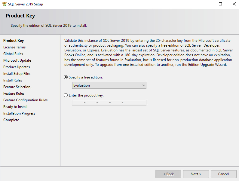
Download SQL Server 2019 from https://www.microsoft.com/en-us/sql-server/sql-server-downloads onto the database server.
Run the SQL Server 2019 executable.
Select the Custom installation type.
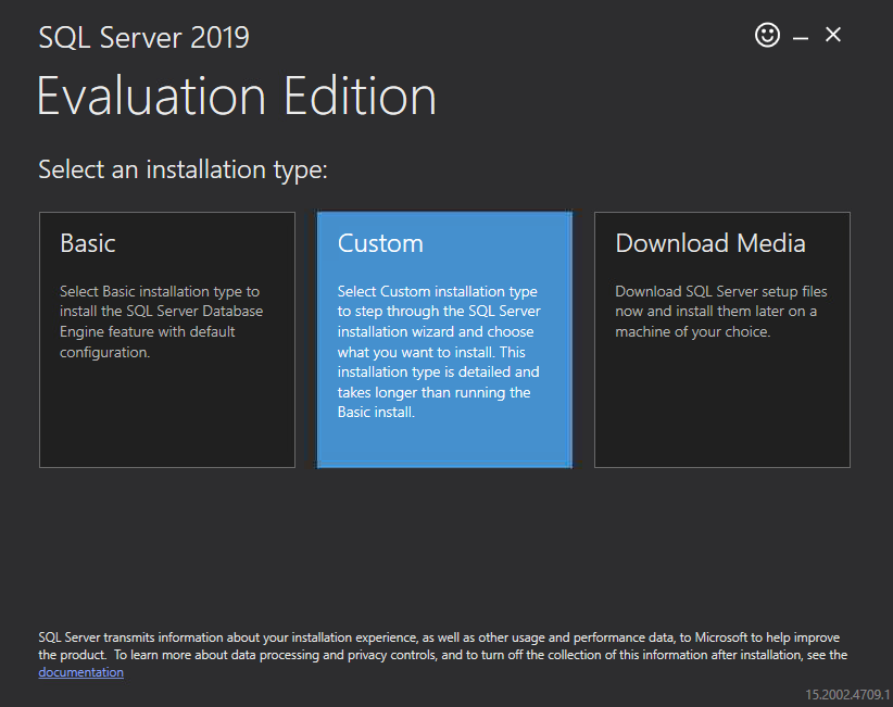
Specify the download location and select Install.
Allow the installer to download the SQL Server 2019 package.
The SQL Server Installation Center should automatically open. From the left menu panel, select Installation. Select the option New SQL Server stand-alone installation or add features to an existing installation.
Enter the product key or select a free edition of the software. Then select Next.
Read and accept the License Terms. Then select Next.
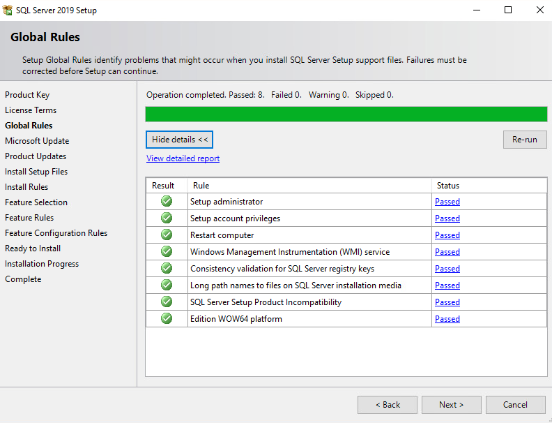
Ensure that all the Global Rules have passed. Then select Next.
To use Microsoft Update to automatically deliver updates, check the box Use Microsoft Update to check for updates (recommended). Then select Next.
Ensure that all the Install Rules have passed. Then select Next.
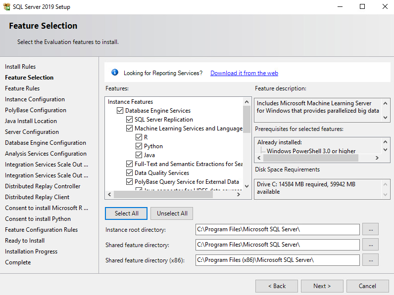
Select the desired features to install. Then select Next. Complete the sections for the selected features.
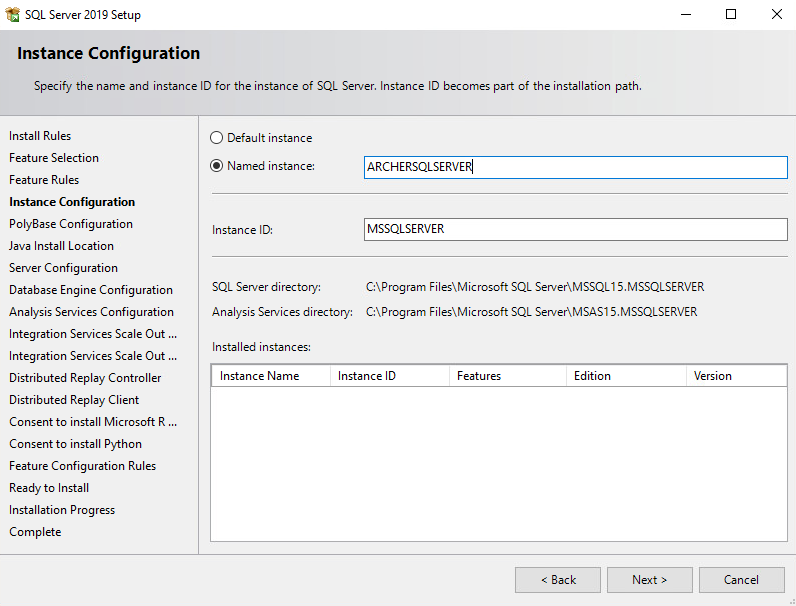
In the Instance Configuration section, select the Named instance radio button and choose a name for the database server, or select the Default instance radio button to use the default name. Then select Next.
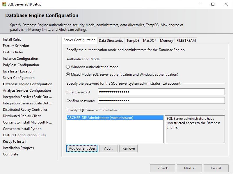
In the Database Engine Configuration section, select the desired Authentication Mode. Select Add Current User to add the current user as a SQL Server administrator and select Next.
Ensure that all the Feature Configuration Rules have passed and select Next.
Confirm the selected settings are desired and select Install.
Once the installation completes, select Close.
2.8.1.2 Create the Archer IRM Databases
Download SQL Server Management Studio (SSMS) from https://aka.ms/ssmsfullsetup. Follow the installation steps.
Once installed, open SSMS.
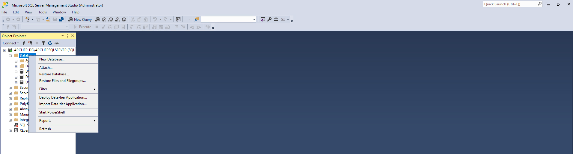
Expand the ARCHERSQLSERVER tree. Right-click on Databases and select New Database. Create three databases: ArcherInstanceDB, ArcherConfigurationDB, and ArcherLoggingDB.
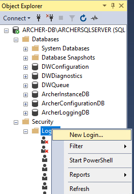
Next, create a local Administrator user. Right-click Security and select New Login.
Under the General tab, input the Login Name and select the SQL Server Authentication radio button. Create a password for this user. These credentials will be used during the Archer IRM installation.
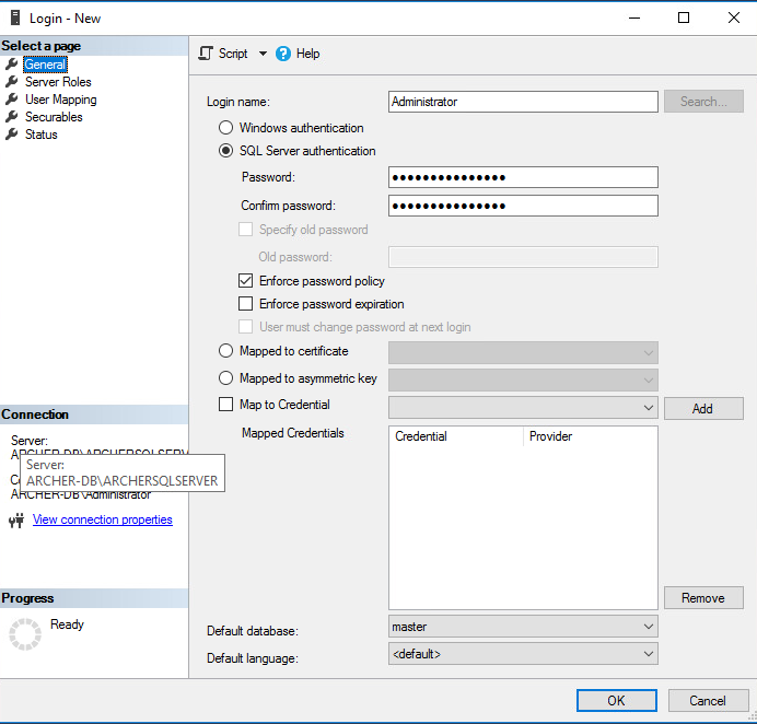
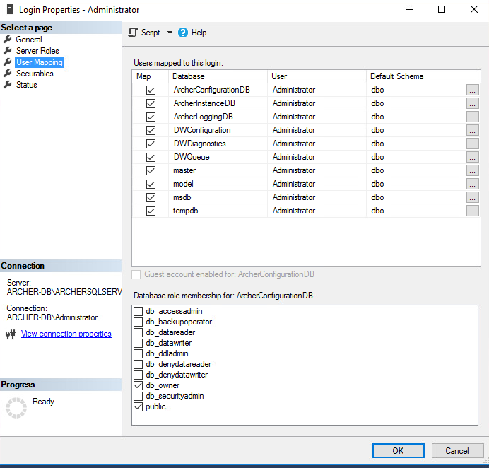
Navigate to the User Mapping tab. Ensure all the databases have the Default Schema set to dbo. Also, ensure that db_owner is selected for each database under the Database role membership section. Select OK.
2.8.1.3 Install Internet Information Services on the Web Server
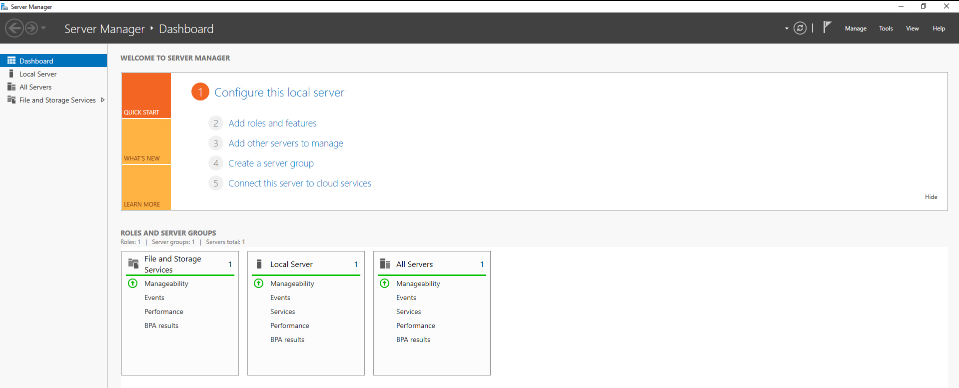
On the web server, open Server Manager.
Under Manage, select Add Roles and Features.
Select Next.
Select the Role-based or feature-based installation radio button. Select Next.
Select the Web Server (IIS) server role. Then select Next.
In the pop-up window, select Add Features.
Select Next.
Select Next.
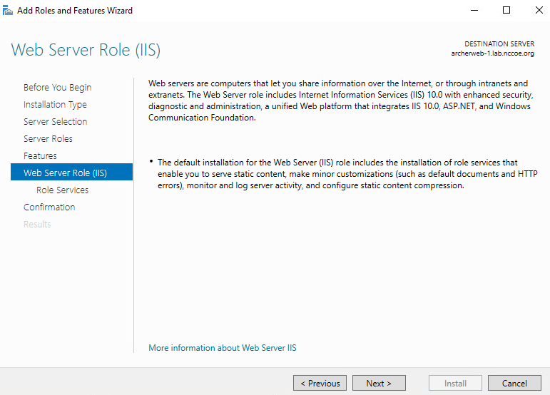
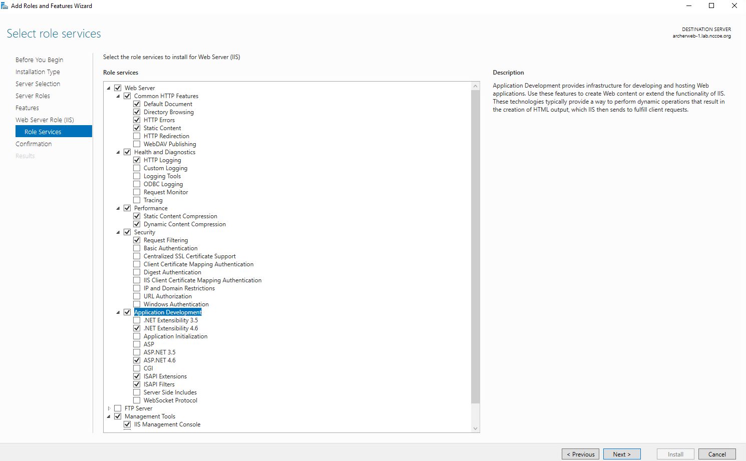
Ensure that the Role Services shown below are selected. Then select Next.
Confirm that the selected options are correct and select Install.
Once the installation completes, select Close.
Restart the computer.
2.8.1.4 Configure IIS
Open the IIS application.
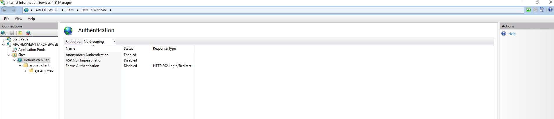
Click on the web server in the left pane. Select Authentication.
Ensure that Anonymous Authentication is enabled and ASP.NET Impersonation and Forms Authentication are disabled for the Default Web Site.
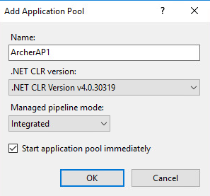
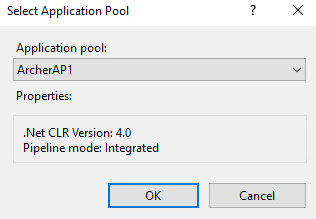
Expand the web server tree and select Application Pools. In the far-right pane, select Add Application Pool.
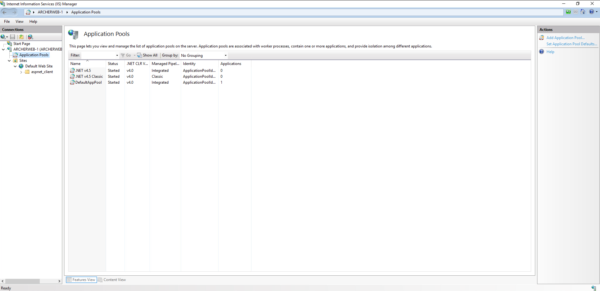
Add a name to the Name input field. Ensure that Managed pipeline mode is set to Integrated and that Start application pool immediately is selected. Then, select OK.
Right-click on the newly created application pool and select Advanced Settings. Under Process Model, select the ellipsis button that is next to the Identity field.
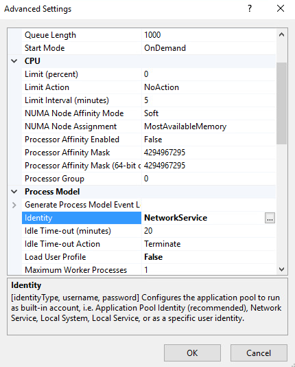
Select Custom account, select Set, and enter the appropriate information. Then select OK.
Click on the web server. In the far-right pane, select Restart.
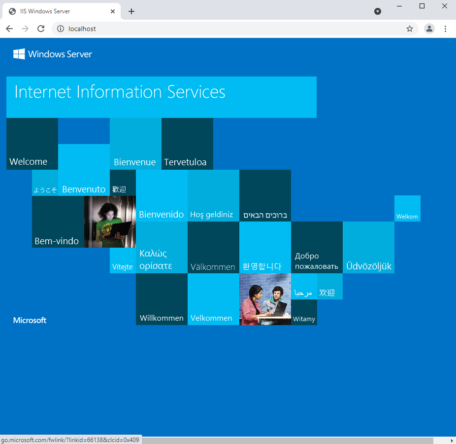
Open a browser and navigate to localhost. If the screen below is shown, then the web server is running properly, and Archer IRM can now be installed.
2.8.2 Archer IRM Installation
Before installing Archer IRM, .NET Framework version 4.7.2 must be installed. It can be downloaded at https://dotnet.microsoft.com/download/dotnet-framework/net472.
Extract the zip file that was downloaded from the Archer IRM download page.
Open the folder and run the executable ArcherInstall.
Accept the License Agreement and select Next.
Select Next.
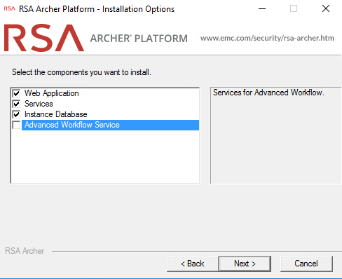
For the web server, make sure the components Web Application, Services, and Instance Database are selected, then select Next.
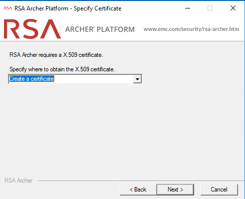
Select Create a certificate from the dropdown menu and select Next.
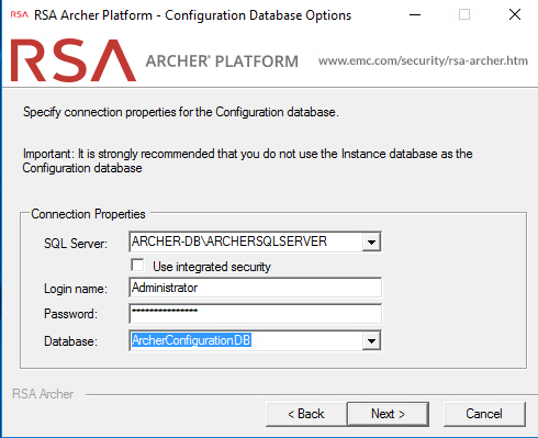
Select the database server that was previously created. Enter the credentials that were created in SSMS. Then select the configuration database from the dropdown menu and click Next.
Select the preferred language from the dropdown menu and select Next.
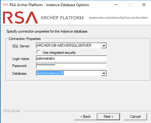
Repeat step 8 and select the instance database from the dropdown menu. Then select Next.
Select the time zone and select Next.
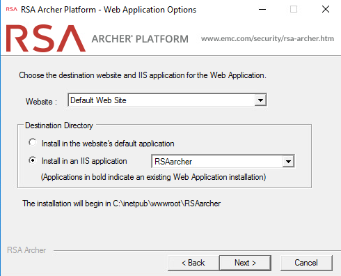
Select Default Web Site as the website location and choose the Install an IIS application radio button. Select RSAarcher from the dropdown menu. Then select Next.
To add an Instrumentation Database, repeat step 8 and use the ArcherLogging database that was created in SSMS. Otherwise, select Not using Archer IRM Instrumentation service. Select Next.
Specify the account to run the services. Then select Next.
Confirm or edit the installation paths for the services and application files. Select the Create Archer IRM program group for all users radio button. Then select Next.
Confirm or edit the path for installation logs. Then select Next.
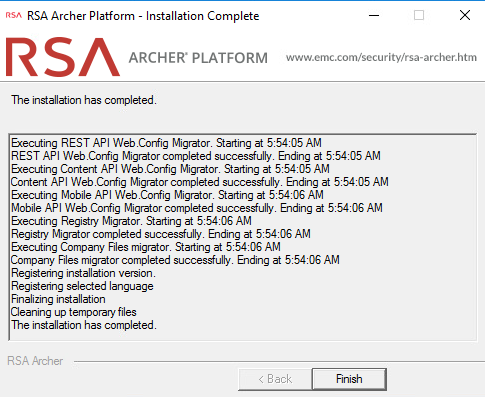
Select Install and wait for the installation to complete. Once completed, select Finish.
2.8.2.1 Configure Options in the Control Panel
Open the RSA Control Panel.
In the left pane, select Add New Instance.
Enter a name for the instance in the Instance Name field. Select Go.
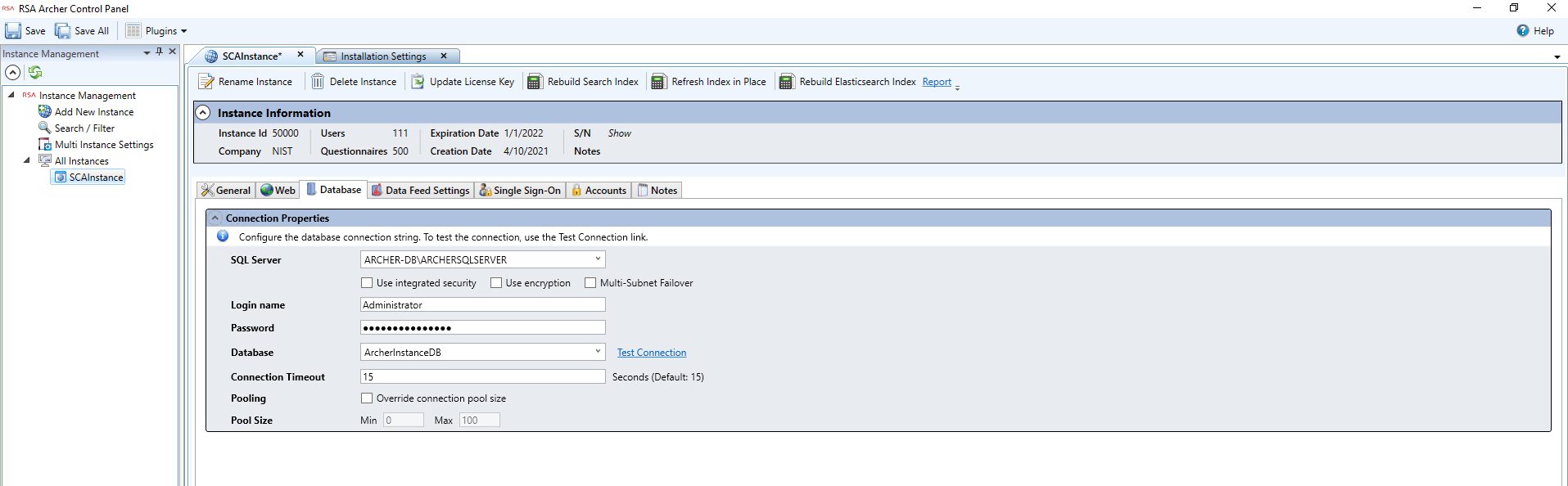
Double-click on the new instance. Input the required information in the General, Web, and Database tabs. When completed, click Save in the top left corner.
2.8.2.2 Add New Application to Application Pool
Navigate back to IIS. Expand the web server directory, expand the Sites directory, and expand the Default Web Site directory.
Select the RSAarcher site. Click on Authentication and ensure that Anonymous Authentication is the only thing that is enabled.
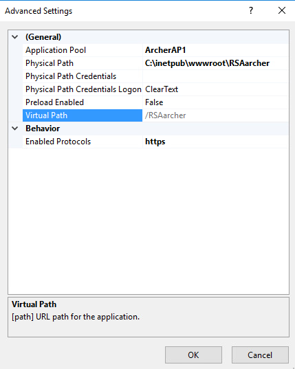
Right-click on the RSAarcher site and select Manage Application > Advanced Settings.
Click on Application Pool and select the ellipsis button. You will see a screen similar to the following:
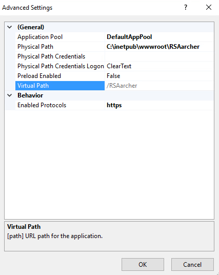
Select the application pool that was previously created and select OK.
Select OK. You should see something similar to the screenshot below:
Restart the Archer IRM site.
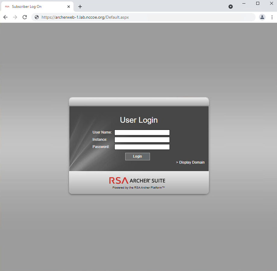
Open a browser and navigate to the URL that was set in the RSA Control Panel application. If the following page displays, then Archer IRM installed successfully.
2.9 Seagate
Seagate contributed three hard drives (Table 2‑6) stored within a 2U12 enclosure. As described in Section 2.7.2, the enclosure is connected to our demonstration Intel server via a Serial Attached SCSI (SAS) interface. The demonstration server did not have the required SAS interface, so we purchased a Broadcom 9500-8e Tri-Mode Storage Adapter to complete the connection.
Table 2‑6 Seagate Hardware Contribution
Machine Name |
Operating System |
Manufacturer |
Model |
|---|---|---|---|
N/A |
N/A |
Seagate |
Exos 18TB Self Encrypting Hard Disk Drive x 3 |
N/A |
N/A |
Seagate |
Exos E 2U12 Rackmount Enclosure |
Once the enclosure is connected to the server, power on the server into the native Linux environment. Execute the lshw command which prints detailed hardware information about the server. The output should resemble the following for one of the Seagate drives. Note that because these are SAS drives there are two paths to the drive. As a result, you will notice two /dev/sdx devices pointing to the same physical drive.
\*-disk:0
               description: SCSI Disk
               product: ST18000NM005J
               vendor: SEAGATE
               physical id: 0.0.0
               bus info: scsi@0:0.0.0
               logical name: /dev/sdb
               version: ET02
               serial: ZR5056HD0000C107GP5G
               size: 16TiB (18TB)
               capacity: 45TiB (50TB)
               capabilities: 7200rpm
               configuration: ansiversion=7 logicalsectorsize=512 sectorsize=4096
Additionally, we recommend using Seagate’s command line interface tool that communicates with the drives via the Trusted Computing Group (TCG) Storage API to confirm successful integration. Use the following command to print drive information:
python3 sed_cli.py --device=/dev/sdb --operation=printdriveinfo
2.10 IBM QRadar
This section describes the installation of the IBM QRadar system for this demonstration. Our instantiation of IBM QRadar is viable for a lab environment, but the reader is encouraged to refer to the architecture planning guide on the IBM website for specific guidance for your environment.
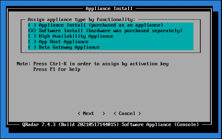
We opted to install the full IBM QRadar suite onto a single virtual machine via an ISO provided by the IBM engineering team. Note that Red Hat Enterprise Linux Server V7.6 (or binary equivalent) must be deployed on the virtual machine before the QRadar installation. Once this prerequisite is met, boot the virtual machine using the ISO provided by IBM. This process will be unique to your environment. Next, follow the instructions provided by the IBM documentation website. The remainder of this section includes example screenshots from the installation wizard we used in our environment.
Select the Software Install option for the appliance type.
For the functionality, select “All-In-One” Console.
Select Normal Setup (default) as the type of setup.
Either manually adjust the date and time, or add the name or IP address of a Network Time Protocol (NTP) server to automatically update the date and time.
Select the appropriate time zone.
Select the appropriate network adapter that will allow communication with the installed system.
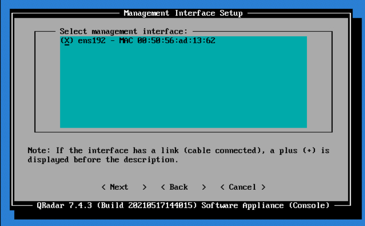
Enter the network information for this installation. Note that only static addresses are supported.
Set the Admin user password.
Set the Root password for console access.
2.10.1 WinCollect Agent
On a separate Windows Server system, configure and install the WinCollect agent. This component polls the remote hosts (laptops), and then sends event information to QRadar.
Install the WinCollect application on the QRadar system if not already present or upgrade to the latest version. This process is documented on the IBM website.
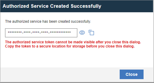
Create an authentication token so that the managed WinCollect agents can exchange data with QRadar appliances. This process is documented on the IBM website. Note that you will not be able to retrieve the token from QRadar after it has been created.
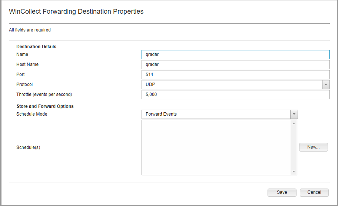
Configure a forwarding destination host for the log source data. This process is documented on the IBM website. Enter the appropriate values for your environment.
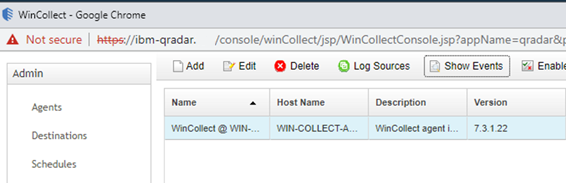
Install the managed WinCollect agent on the Windows Server host. This process is documented on the IBM website. If successful, the agent will appear in the QRadar console under Admin > Data Sources > WinCollect > Agents.
2.11 Integrations
This section describes the steps we took to configure and integrate the products described earlier in this volume. The integrations are generally network-based and require connectivity both between the systems and to Internet-based cloud services.
2.11.1 Microsoft Endpoint Configuration Manager and Platform Validation Tools
For the Intel laptops, a command-line version of the AutoVerify tool named TSCVerifyUtil periodically monitors the changes to laptop components. A custom PowerShell script installed on each laptop and run every hour via task scheduler captures the result of TSCVerifyUtil execution and stores it in the Windows registry. This section describes how to configure Microsoft Endpoint Configuration Manager to run a configuration baseline which monitors the results of the customized PowerShell script. This data is reflected in the Archer IRM dashboard.
Similarly for HP Inc. and Dell laptops, the HIRS-ACA Windows-based Provisioner periodically monitors the changes to laptop components. We chose to use the same monitoring approach for consistency – the Windows task scheduler captures the result of the Provisioner execution and stores it in the Windows registry. Repeat this section to configure Microsoft Endpoint Configuration Manager with the HIRS Provisioner, changing input where noted.
2.11.1.1 Set Up Configuration Item
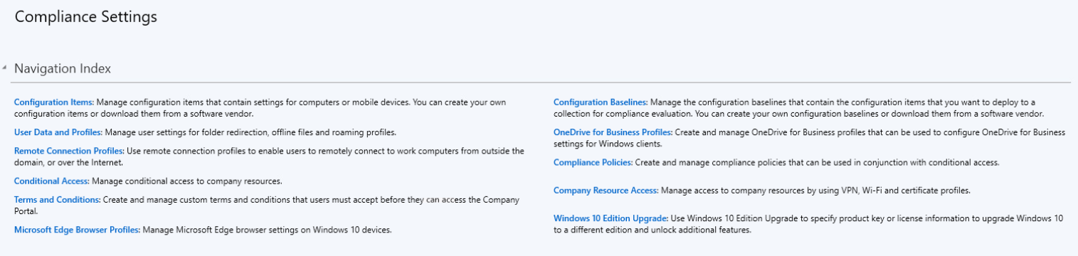
In the Microsoft Endpoint Configuration Manager console, under Assets and Compliance > Overview, select Compliance Settings.
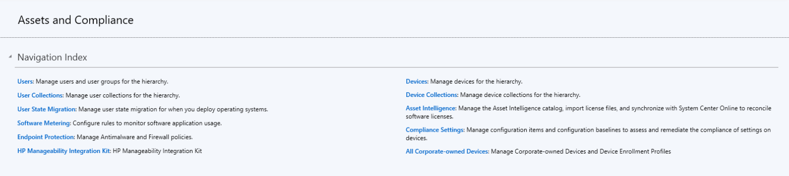
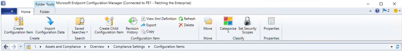
Next, select Configuration Items.
From the Home panel at the top, select Create Configuration Item.
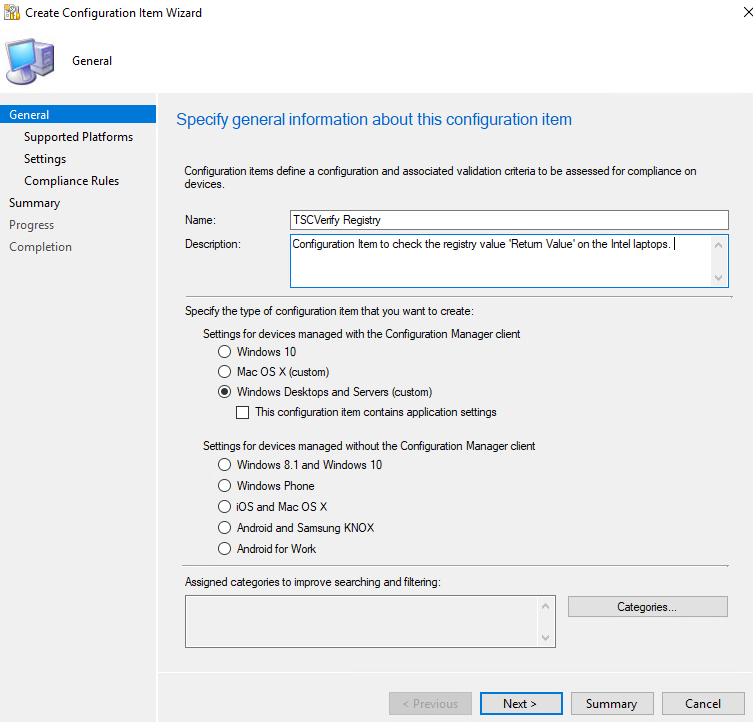
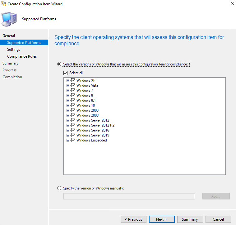
Enter a name and description for the configuration item in the Name and Description fields. Ensure that Windows Desktops and Servers (custom) is selected. Then select Next.
Ensure that all versions are selected and click Next.
On the Settings tab, select New.
On the General tab, enter a name and description in the Name and Description fields. For Setting type, select Registry value from the dropdown. For Data type, selection String from the dropdown. To specify the registry value, select the appropriate Hive Name and enter the Key Name and Value Name in their respective fields (Note: When configuring the HIRS Provisioner, use
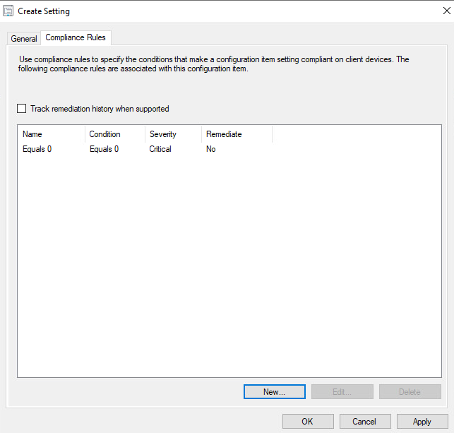
SOFTWARE\HIRS\provisioneras the Key Name). Next, switch to the Compliance Rules tab.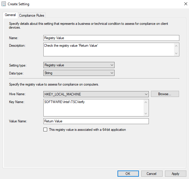
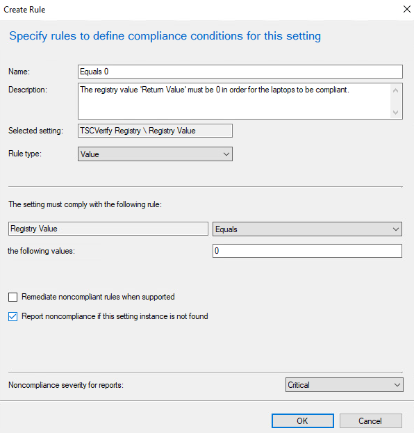
Select New.
Specify the name and description for the rule in the Name and Description fields. For Rule type, select Value from the dropdown. Under The setting must comply with the following rule, select Registry Value and Equals, and enter 0 (zero) in the following values: field. Ensure that Report noncompliance if this setting instance is not found is selected. Choose the Noncompliance severity for reports appropriate for your environment. Then select OK.
Select Apply. Then select OK.
Review the configurations on the Summary page. After confirming that the configurations are correct, select Next.
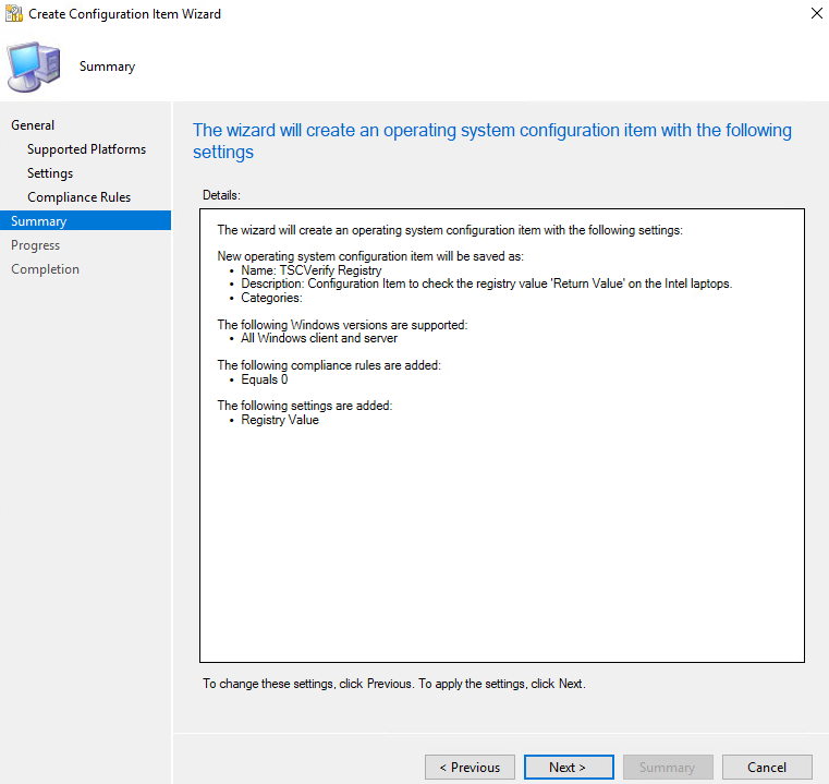
After the wizard completes, select Close.
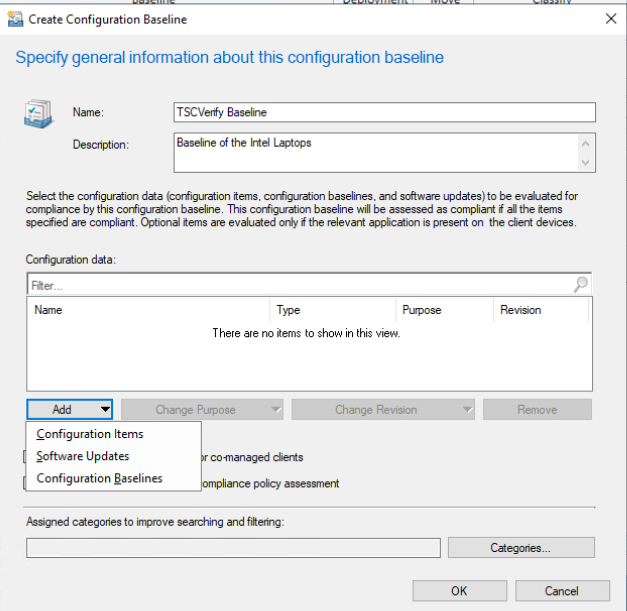
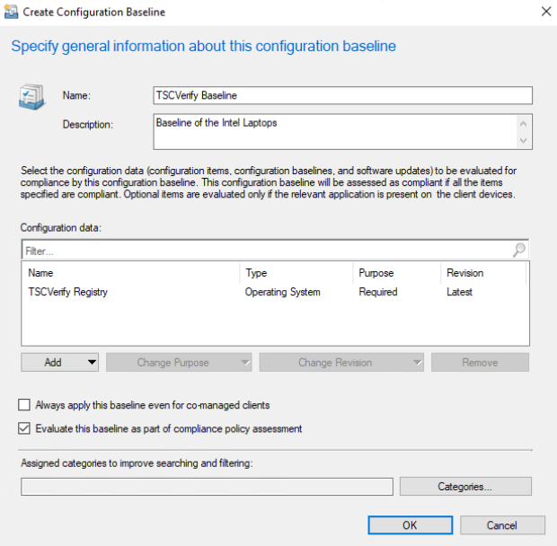
2.11.1.2 Set Up Configuration Baseline
In the Microsoft Endpoint Configuration Manager console, under Assets and Compliance > Overview, select Compliance Settings.
Next, select Configuration Baselines.
From the Home panel at the top, select Create Configuration Baseline.
Provide a name and description for the configuration baseline in the Name and Description fields. Next, select Add and choose Configuration Items.
Select the previously created configuration item from the list and select Add.
Select OK.
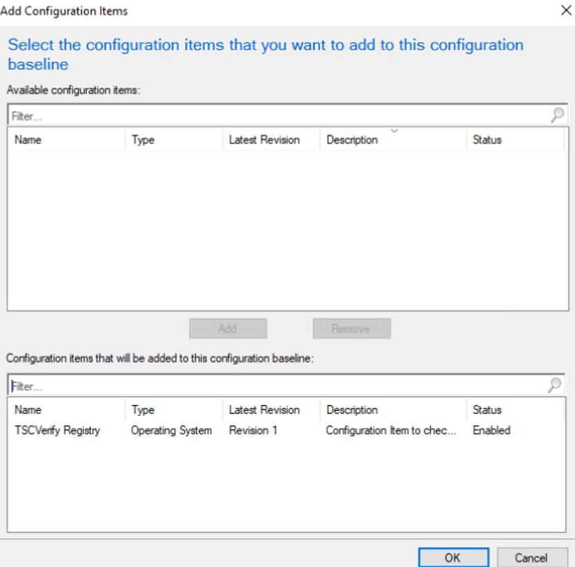
Select OK.
2.11.1.3 Set Up Registry Entry on Intel Devices
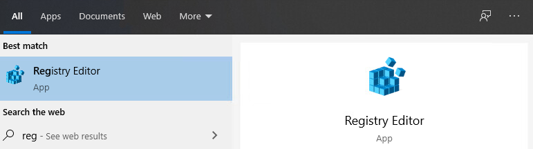
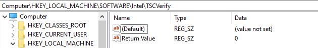
On the Windows 10 laptop, go to Start, search for the Registry Editor, and open that program.
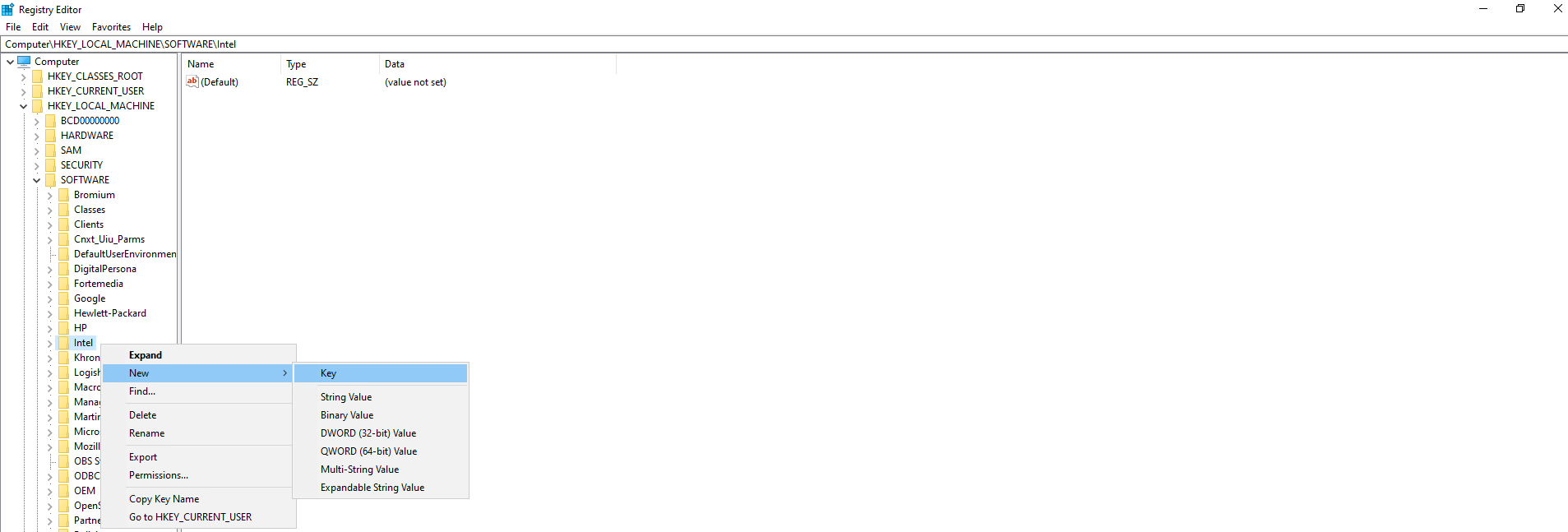
Find the Intel folder located in HKEY_LOCAL_MACHINESOFTWARE. Right click and select New > Key. Name the key TSCVerify.
Select the TSCVerify key, right-click and select New > String Value.
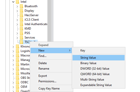
Enter Return Value in the Name field.
2.11.1.4 Run Script Via Task Manager
Place the script onto the local machine (snippet shown below). A copy of this script can be obtained from our repository.
# Run Scan and capture exit code.
# 0=No components have changed and platform certificate validation
passed
# 1=At least one component has changed OR platform certificate
validation failed
# 2=At least one component has changed AND Platform Certificate
validation failed

# Write-Output "Starting DPD file scan and compare..."
$tscpinfo = New-Object System.Diagnostics.ProcessStartInfo
$tscpinfo.FileName = "TSCVerifyTool_3.40.exe"
$tscpinfo.WorkingDirectory = $artifactdirectory
$tscpinfo.RedirectStandardError = $true
$tscpinfo.RedirectStandardOutput = $true
$tscpinfo.UseShellExecute = $false
$tscpinfo.Arguments = "SCANREADCOMP -in $dpdfile"
$dpdprocess = New-Object System.Diagnostics.Process
$dpdprocess.StartInfo = $tscpinfo
$dpdprocess.Start() \| Out-Null
$stdout = $dpdprocess.StandardOutput.ReadToEnd()
$dpdprocess.WaitForExit()

# Write-Output "Starting Platform Certificate validation ..."
$tscpinfo.Arguments = "PFORMCRTCOMP -in $platformcertificatefile"
$platformcertprocess = New-Object System.Diagnostics.Process
$platformcertprocess.StartInfo = $tscpinfo
$platformcertprocess.Start() \| Out-Null
$stdout = $platformcertprocess.StandardOutput.ReadToEnd()
$platformcertprocess.WaitForExit()

# If the return value is nonzero, then the computer is not compliant
$retValue = $dpdprocess.ExitCode + $platformcertprocess.ExitCode
Write-Output $retValue

# Add retValue to registry location
$regPath = "HKLM:\SOFTWARE\Intel\TSCVerify"
Set-ItemProperty -Path $regPath -Name "Return Value" -Value $retValue
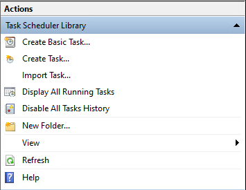
From the Start Menu, search for Task Scheduler and open the program.
Under the Actions panel, select Create Basic Task.
Fill in the Name and Description fields. Then select Next.
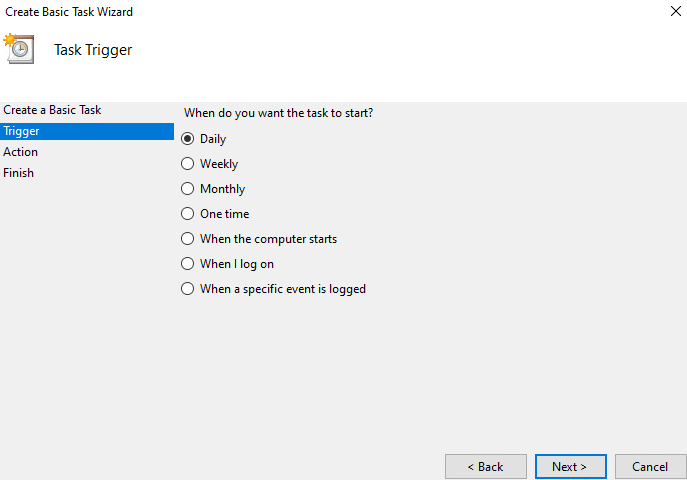
Select the frequency for this task to run. Then select Next.
Select the start date and time for the task. Then select Next.
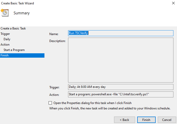
Select the action Start a program. Then select Next.
In the Start a program section, type the following in the Program/script field: powershell.exe. Next, add the following to the add arguments (optional) field: -file “<Location of script>”. Then select Next.
Confirm the settings are correct and select Finish.
On the main page of Task Scheduler, select the newly created task, right-click it, and select Properties.
On the General tab, under Security Options, change the user to SYSTEM. Next, ensure that the option Run with highest privileges is checked.
Navigate to the Triggers tab. Select the existing trigger and select Edit.
Under the Advanced Settings section, ensure that Repeat task every 1 hour for a duration of Indefinitely is checked, as well as Enabled. Select OK.
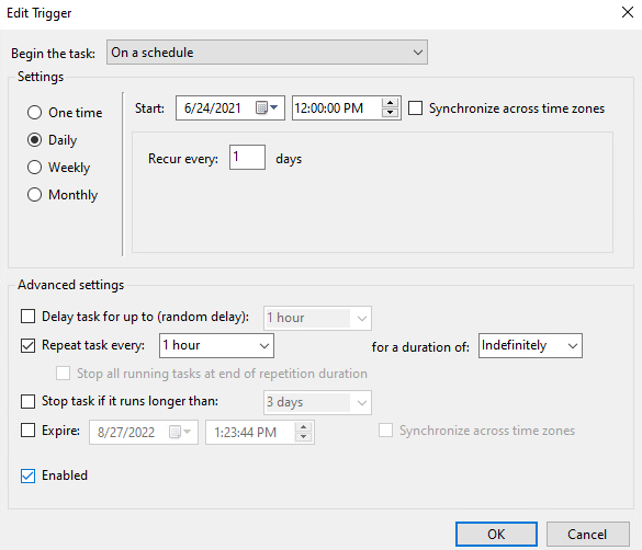
Select OK.
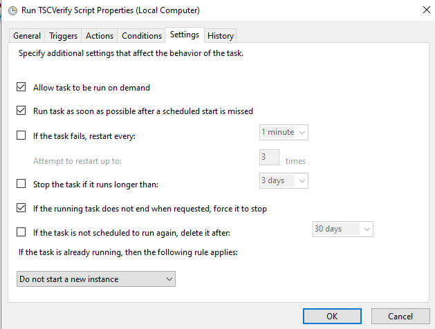
Navigate to the Settings Tab and ensure the following are checked, then select OK.
Allow task to be run on demand
Run task as soon as possible after a scheduled start is missed
If the running task does not end when requested, force it to stop
Select other options to suit your environment.
2.11.2 Archer IRM DataFeed Integrations
Archer IRM serves a dual role in the prototype demonstration - the Asset Management and Discovery System and the IT Administrator Dashboard. This section will detail the steps necessary to integrate Archer IRM with the PMCS, the Eclypsium Firmware Analytics Platform, and Microsoft Configuration Manager, which will form the basis of the Asset Management and Discovery System. From there, we will describe how to create a dashboard using the data gathered from the preceding integrations.
2.11.2.1 Create the Devices Application
Before platform and firmware data can be stored in the in the Asset Management and Discovery System, the Archer IRM application must be created. For this task, we leverage the default Devices application described as the central repository of knowledge about your business-critical devices.
We use the Devices application as a starting point for our customizations that are described in the section. Your organization may have additional requirements that can also be integrated into this solution. As a user with administrative privileges, ensure your installation has the IT Asset Catalog solution included before starting the following procedures.
In the administration menu, navigate to Application Builder > Solutions. Select Add New.
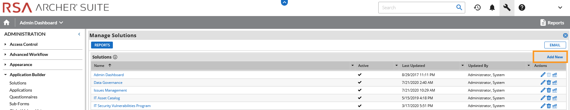
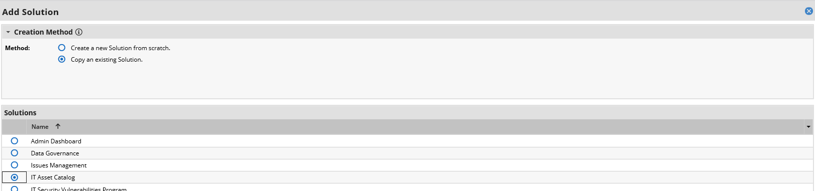
Select Copy an existing Solution and the IT Asset Catalog. Click OK.
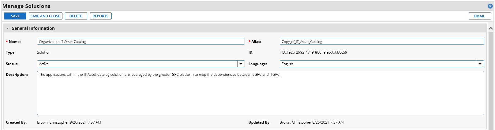
Enter an identifier for the catalog in the Name field. Click SAVE AND CLOSE.
2.11.2.1.1 Create Supporting Applications
Next, create custom applications that will augment the default Devices application. Refer to Appendix B as you work through creating the supporting application. The application in the following steps, named Components, will store the components associated with each computing device that satisfies acceptance testing.
In the administration menu, navigate to Application Builder > Applications. Select Add New.
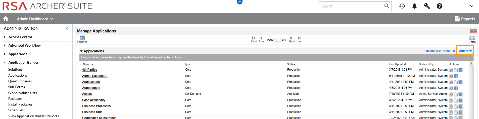
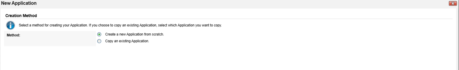
Select Create a new Application from scratch and click OK.
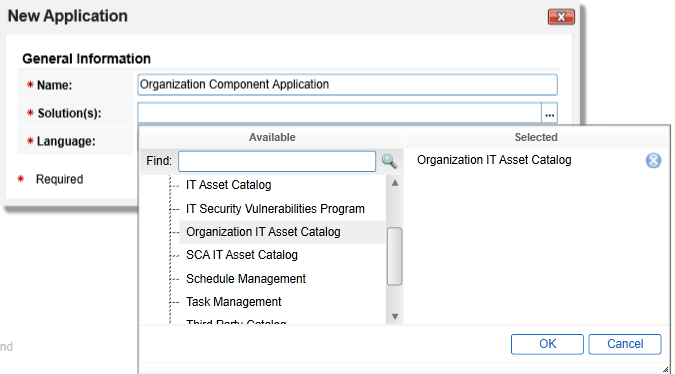
Create an identifier in the Name field and select the solution created earlier. Click OK.
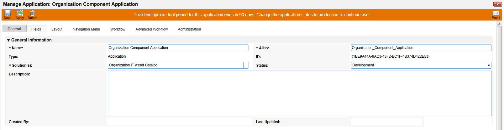
Click Save.
In the next series of steps, we will add several Data Fields to the newly created application. These are like table columns you might define in a relational database. Note that we will only walk through one example, but the steps can be repeated for the remaining data fields. Before starting these steps, download and open the Components application schema from our repository. Some data fields, such as Tracking ID, First Published, and Last Updated are automatically created with each new application and do not need to be repeated.
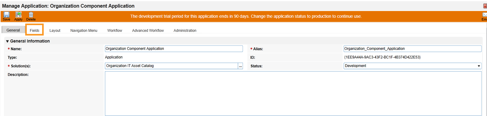
Open the target Components application from the Administration menu under Application Builder > Applications.
Click the Fields tab.
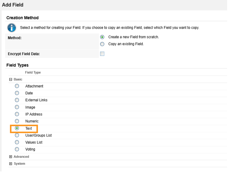
Click Add New. Match the Field Type from Appendix B to the Field Type field in Archer IRM. Click OK.
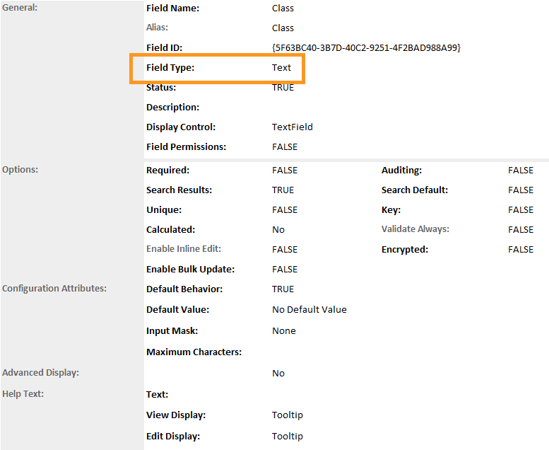
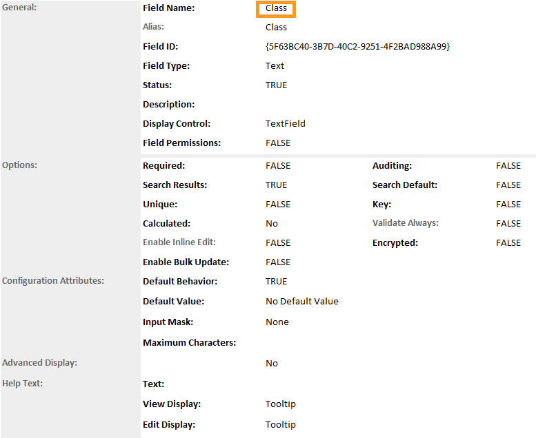
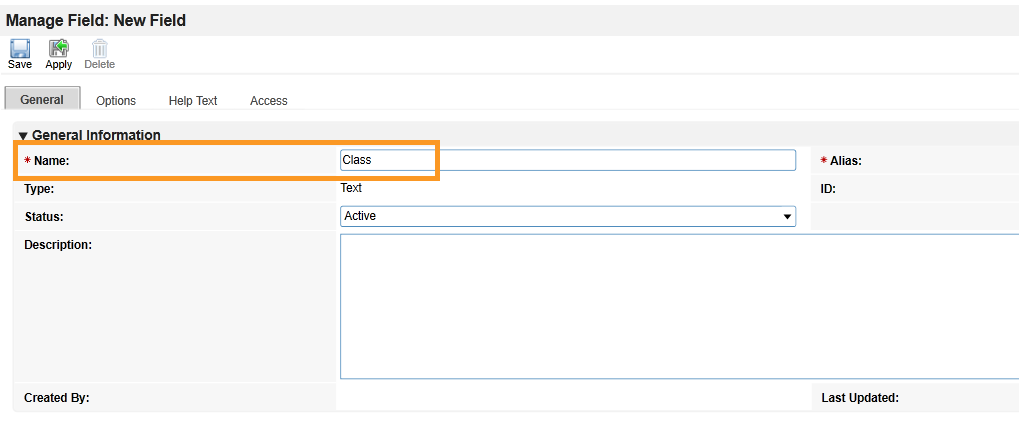
Match the Field Name from Appendix B to the Field Name field in Archer IRM. Click Save.
Repeat this process for all remaining data fields in Appendix B. Refer to the online documentation for other data types that might require additional configuration.
At this point, you have created the first supporting application for the Asset Discovery and Inventory system. Repeat these procedures to create the HP UEFI Configuration Variables, Seagate Firmware Attestation, and Seagate Firmware Hash applications. These applications support the demonstration’s dashboard capability that continuously monitors HP Inc.’s laptop platform security configurations and Seagate measurement values respectively. Make note of these applications as they are also referenced in the integration procedures (Section 2.11.2.2).
2.11.2.1.2 Modify Default Devices Application
In the next series of steps, modify the Devices with custom data fields that support the capabilities of this demonstration. You will also link this application to the supporting applications created in Section 2.11.2.1.1.
Using the Devices table in Appendix B, add the custom data fields using the same method as described in Section 2.11.2.1.1. Note that cross-referenced data fields are links that will automatically create a new data field in the associated application.
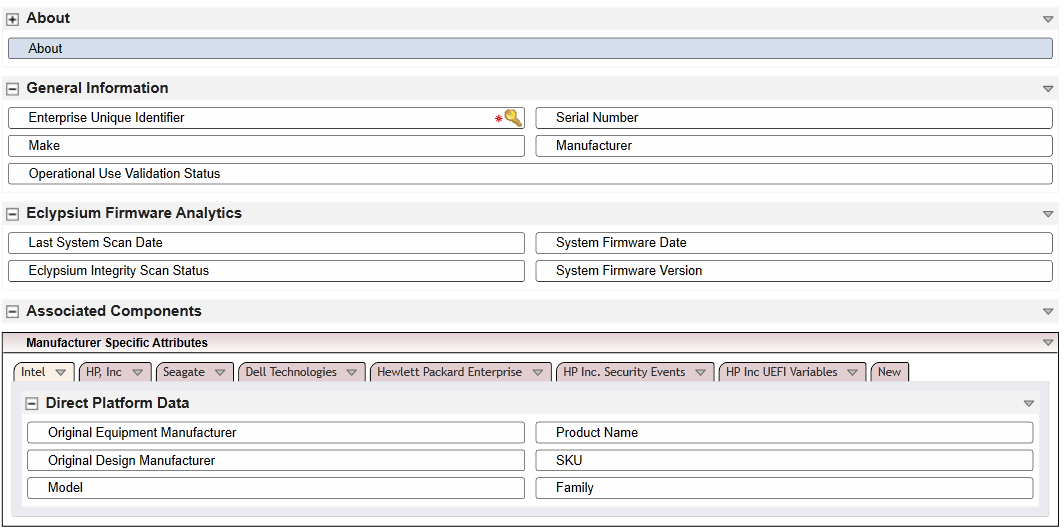
Modify the layout of the Devices application to include data field customizations created in this section. The layout will be used to display detailed information about a computing device that has completed the acceptance testing process. Of note, we have added three sections—General Information, Eclypsium Firmware Analytics, and Associated Components. Use the screenshots below as a starting point for customizations that fit into your organization’s workflow. More information regarding layouts can be found on RSA’s website.
2.11.2.1.3 Modify Default Security Incidents Application
Modify the Security Incidents application with custom data fields that support the capabilities of this demonstration. Using Table 2‑7, add the custom data fields using the same method as described in Section 2.11.2.1.1. Note that cross-referenced data fields are links that will automatically create a new data field in the associated application.
Table 2‑7 Security Incidents Application Custom Data Fields
Data Field Name |
Data Field Type |
Notes |
|---|---|---|
Date/Time QRadar LastUpdate |
Date |
Stores the date from each QRadar Offense |
Incident ID (QRadar) |
Text |
Stores the QRadar Offense unique identifier |
SCA Computing Device |
Cros s-Reference |
Links to the Devices application computing device unique identifier |
2.11.2.2 Create Data Feed Integrations
In this section, the implementer will create data feeds in Archer IRM that will complete the integration with the PMCS, Microsoft Configuration Manager, IBM QRadar, and Eclypsium. The data feeds will periodically pull data from the three data sources and map it to the Devices application created in the preceding section.
2.11.2.2.1 Create Eclypsium Data Feeds
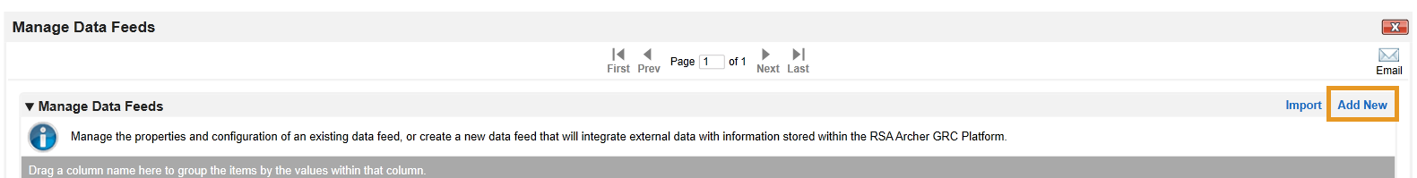
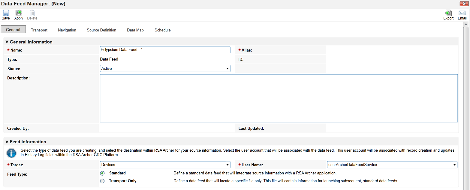
In the Administration menu, navigate to Integration > Data Feeds. Click Add New.
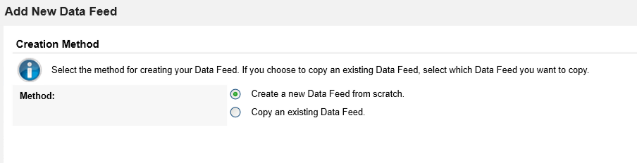
Select Create a new Data Feed from scratch. Click OK.
Create an identifier in the Name field. Select the Devices application created in Section 2.11.2.1 in the Target field.
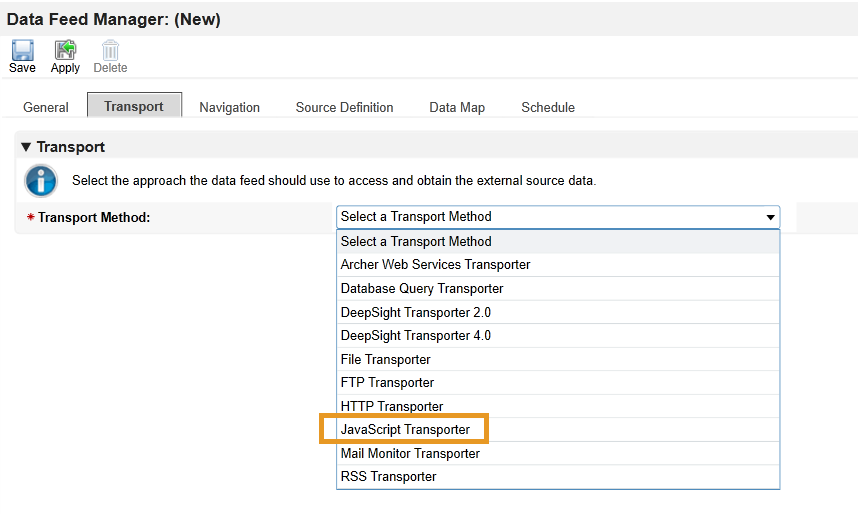
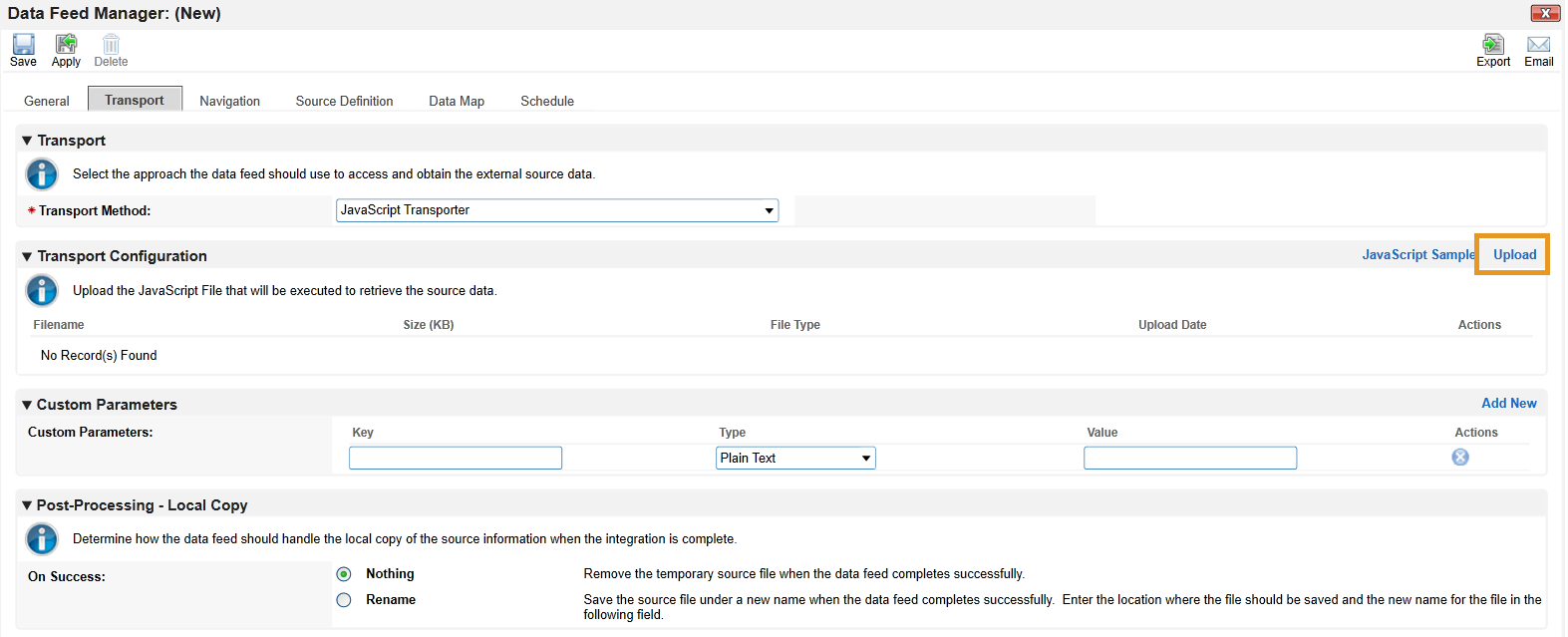
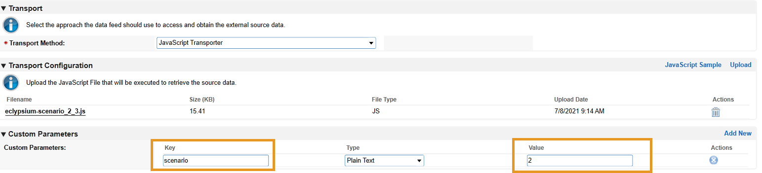
Click the Transport tab. Select JavaScript Transporter.
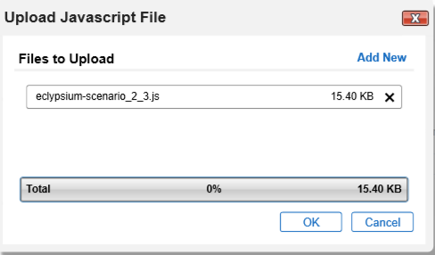
Click Upload in the Transport Configuration section.
Click Add New.
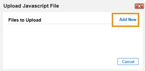
In the file selection modal, select the Eclypsium JavaScript data feed file from the repository. Click OK.
Enter “scenario” in the Key field and “2” in the Value field.
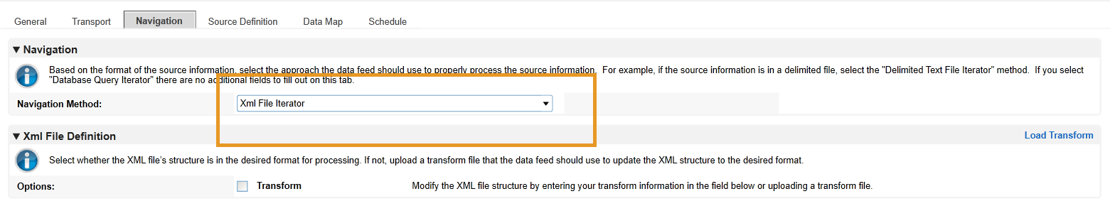
Click the Navigation tab. Ensure XML File Iterator is selected in the Navigation Method dropdown menu.
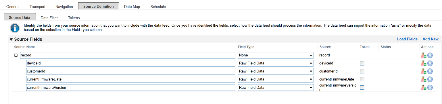
Click the Source Definition tab. In the Source Data sub-tab, select Load Fields. Select the Eclypsium example XML file. The configuration in Archer should populate the Source Fields as follows.
Click the Data Map and tab which will default to the Field Map sub-tab. Drag and drop the source fields onto the application data fields. Due to the large amount of data fields in the Devices application, below we present a truncated view of the mapping.
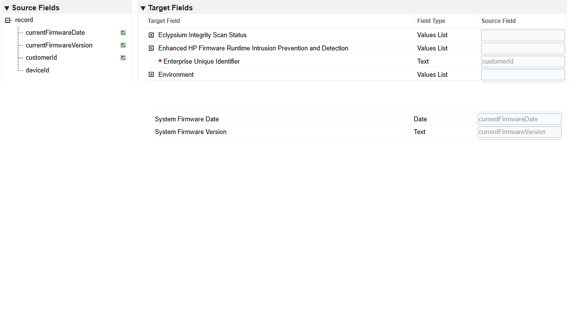
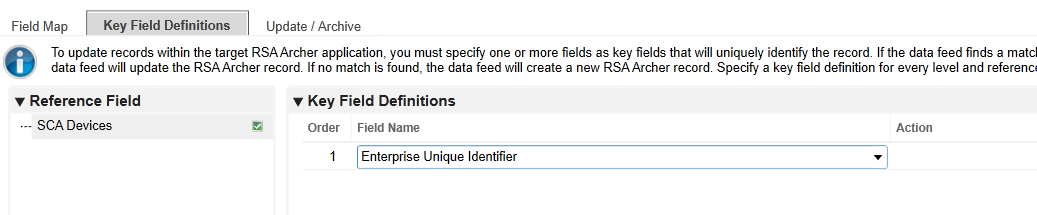
Click the Key Field Definitions tab. Select Enterprise Unique Identifier in the Field Name column.
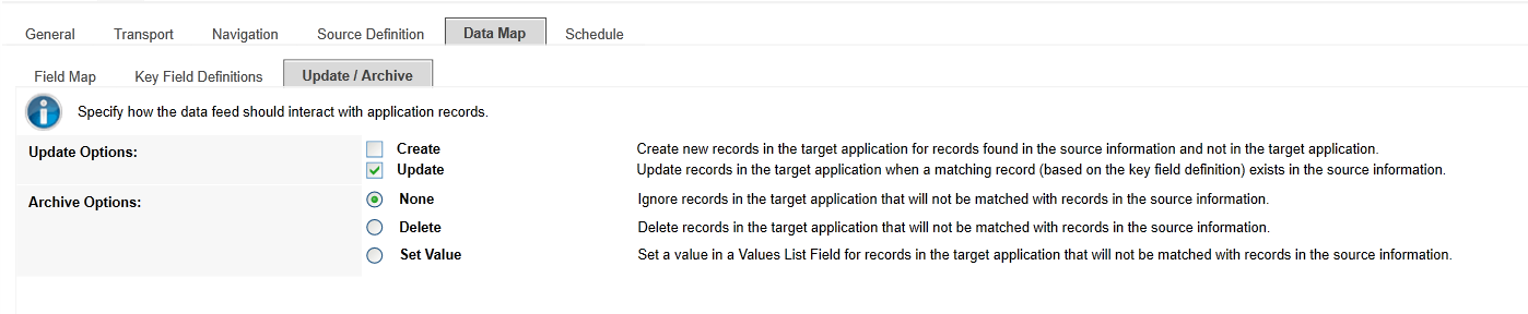
Click the Update / Archive tab. Ensure only the Update option is selected. Choose None for the Archive Options.
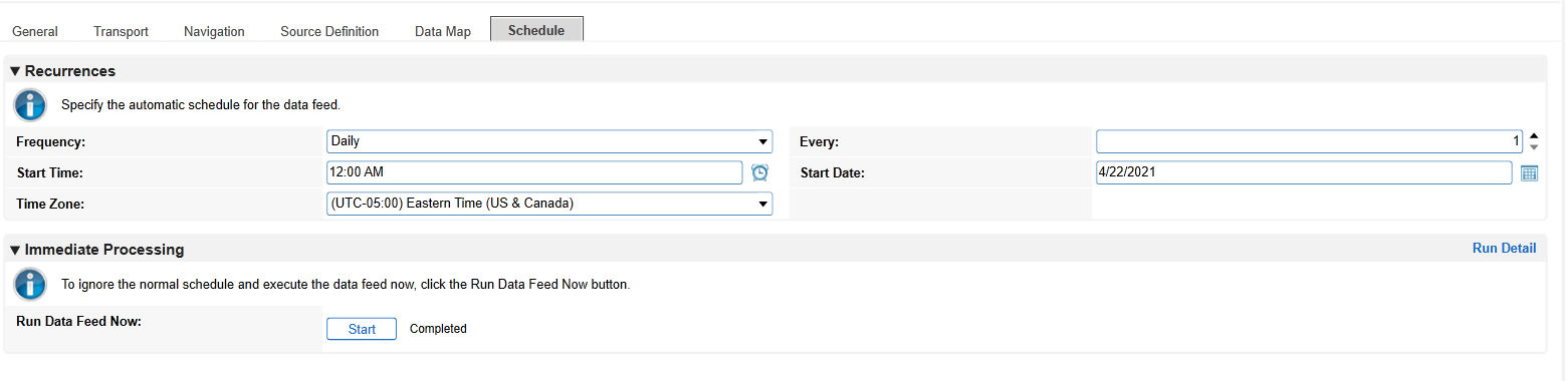
Click the Schedule tab. Select a cadence appropriate for your organization. In this example, we’ve chosen to run the data feed on a daily frequency at 12:00AM.
At this point, the data feed for Eclypsium (Scenario 2) is configured. Scenario 3 is configured with the same process, except that in Step 8, a “3” is used in the Value field instead of a “2”. Click the Start button to confirm that the data feed has been properly configured. Archer IRM will report any errors that are useful for debugging.
2.11.2.2.2 Create Microsoft Configuration Manager Data Feed
Repeat the preceding steps to add the Microsoft Configuration Manager Data Feed with the following modifications:
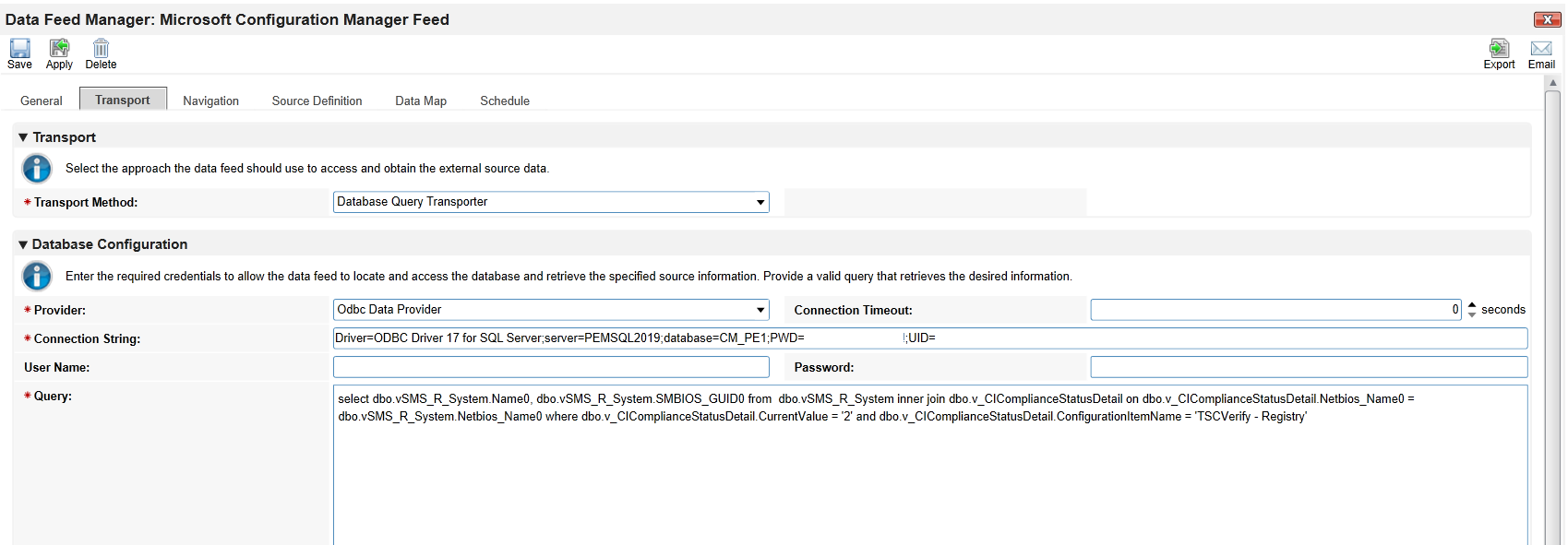
In the Transport tab, select Database Query Transporter. Insert the following values in the form:
Provider
Odbc Data Provider
Connection String
Driver=ODBC Driver 17 for SQL Server;server=PEMSQL2019;database=CM_PE1;PWD=[SQL USER PASSWORD];UID=[SQL USER]
Query
select dbo.vSMS_R_System.Name0, dbo.vSMS_R_System.SMBIOS_GUID0 from dbo.vSMS_R_System inner join dbo.v_CIComplianceStatusDetail on dbo.v_CIComplianceStatusDetail.Netbios_Name0 = dbo.vSMS_R_System.Netbios_Name0 where dbo.v_CIComplianceStatusDetail.CurrentValue = ‘2’ and dbo.v_CIComplianceStatusDetail.ConfigurationItemName = ‘TSCVerify - Registry’
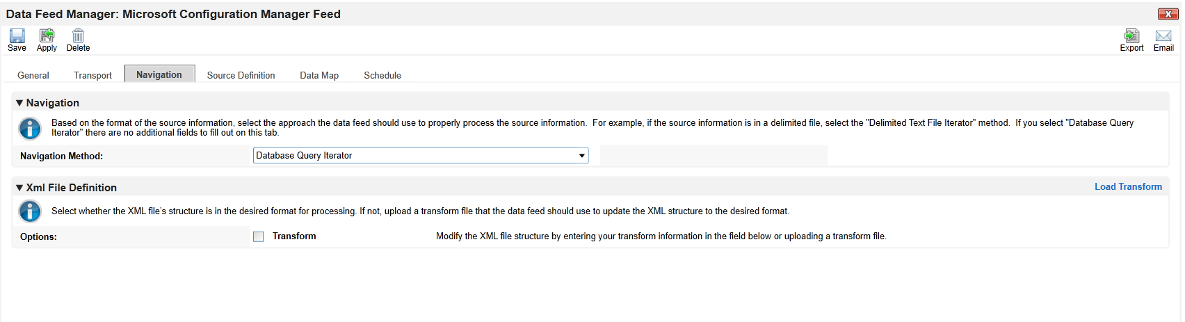
In the Navigation tab, select Database Query Iterator.
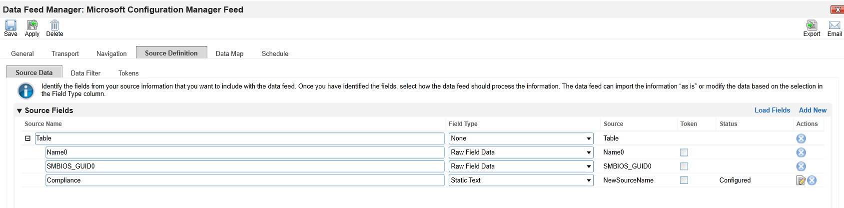
- In the Source Definition tab, add a new Source Field named
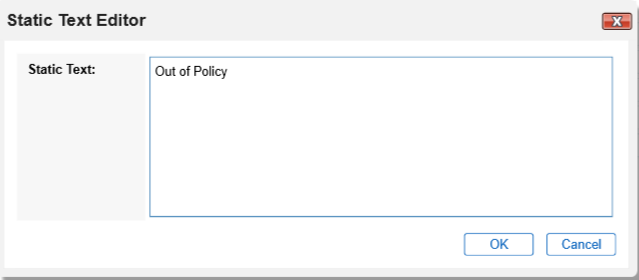
Compliance.
Edit the new Source Field with the static text “Out of Policy”.
In the Field Map sub-tab in the Data Map tab, drag and drop the Source Fields onto the Target Fields as shown in the images below.
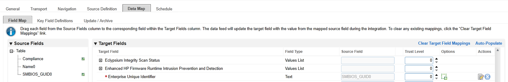

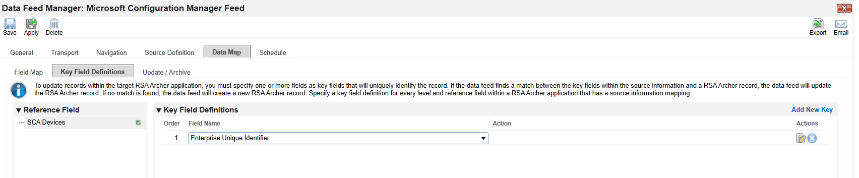
In the Key Field Definitions sub-tab in the Data Map tab, select Enterprise Unique Identifier.
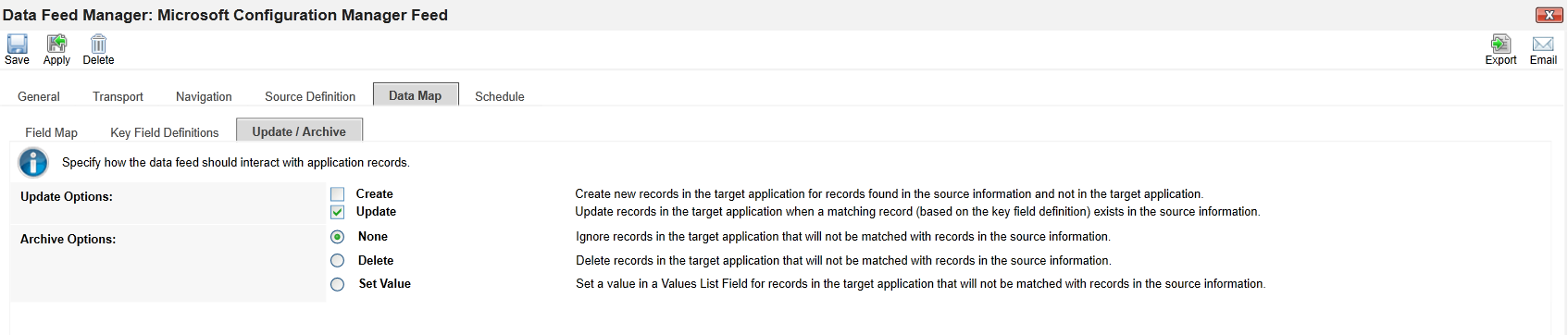
In the Update / Archive sub-tab in the Data Map tab, ensure only Update is selected.
At this point, the Data Feed for the Microsoft Configuration Manager is configured. Click the Start button to confirm that the Data Feed has been properly configured. Archer will report any errors that are useful for debugging.
2.11.2.2.3 Create the PMCS Data Feed
Repeat the initial steps to add the Data Feed for the PMCS with the following modifications:
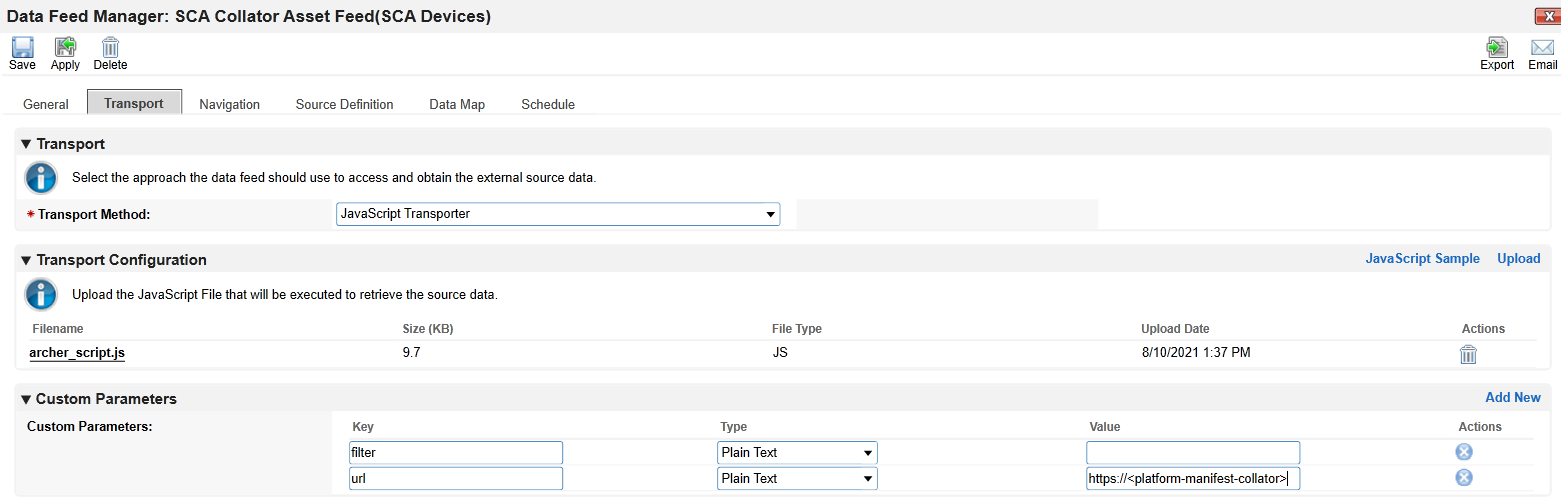
In the Transport tab, upload the custom JavaScript from the project repository. In the Custom Parameters fields, add filter and url keys as shown below. The value for filter may be blank or set to a specific manufacturer (refer to comments in the script for the specific values we used). Set url to the location of the PMCS in your environment.
In the Source Definition tab, upload the example XML file from the project repository. The Source Fields should resemble the following screenshot.
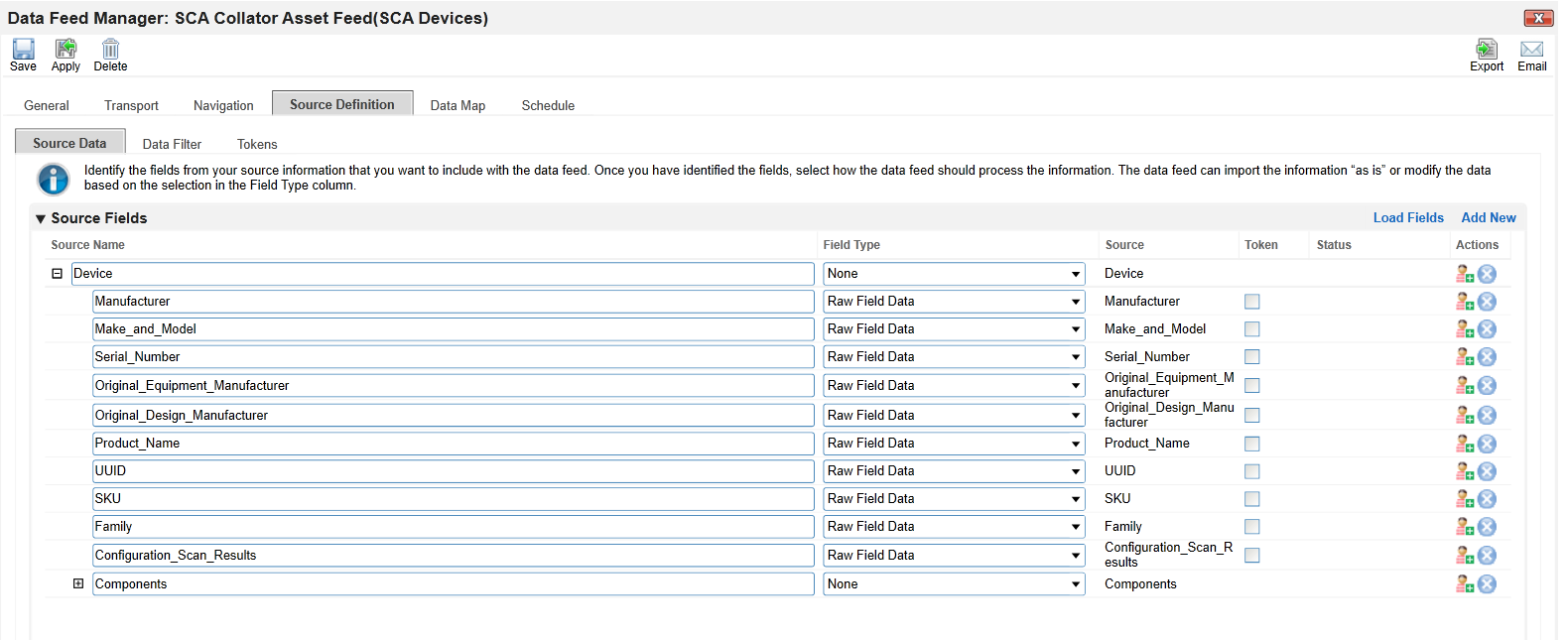
Map the Source Fields to the Target Fields and the Field Map sub-tab in the Data Map tab. Use Table 2‑8 for reference.
Table 2‑8 PMCS Data Feed Source Field to Destination Field Mapping
Source Field |
Destination Field |
|---|---|
/Component/Addresses/Address |
Associated Components/Addresses/Address |
/Component/Class |
Associated Components/Class |
/Component/Field_Replaceable |
Associated Components/Field Replaceable |
/Component/Manufacturer |
Associated Components/Manufacturer |
/Component/Model |
Associated Components/Model |
/Co mponent/Platform_Certificate |
Associated Components/Platform Certificate |
/Compon ent/Platform_Certificate_URI |
Associated Components/Platform Certificate URI |
/Component/Revision |
Associated Components/Revision |
/Component/Serial |
Associated Components/Serial |
/Component/Version |
Associated Components/Version |
UUID |
Enterprise Unique Identifier |
Family |
Family |
Make_and_Model |
Make |
Manufacturer |
Manufacturer/Value |
Original_Design_Manufacturer |
Original Design Manufacturer |
Ori ginal_Equipment_Manufacturer |
Original Equipment Manufacturer |
Product_Name |
Product Name |
Serial_Number |
Serial Number |
SKU |
SKU |
In the Key Field Definitions sub-tab in the Data Map tab, choose Enterprise Unique Identifier as the Key Field definition.
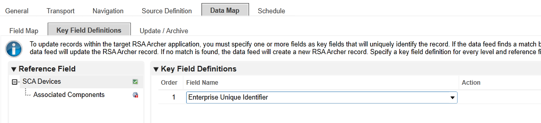
The Data Feed for the PMCS is configured. Click the Start button to confirm that the Data Feed has been properly configured. Archer will report any errors that are useful for debugging.
2.11.2.2.4 Create IBM QRadar Offenses Data Feed
Repeat the steps from Section 2.11.2.2.1 to add the Data Feed for IBM QRadar with the following modifications:
In the Transport Settings section of Source Settings, choose the IBM QRadar script (Integration-ScriptsArcher Integrated Risk Management Data Feed IntegrationsIBM QRadarapp.js) from the project repository.
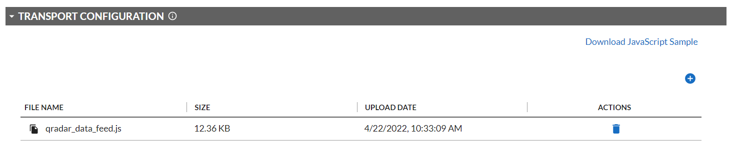
In the Custom Parameters section of the Source Connection tab, enter the hostname of the QRadar system and the API key created in Section 2.11.3.2.4. Ensure that the QRadarAPIKey is of type Protected.
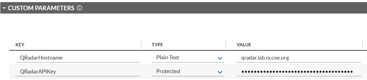
In the Source Data section of the Source Definition tab, upload the example XML QRadar response file.
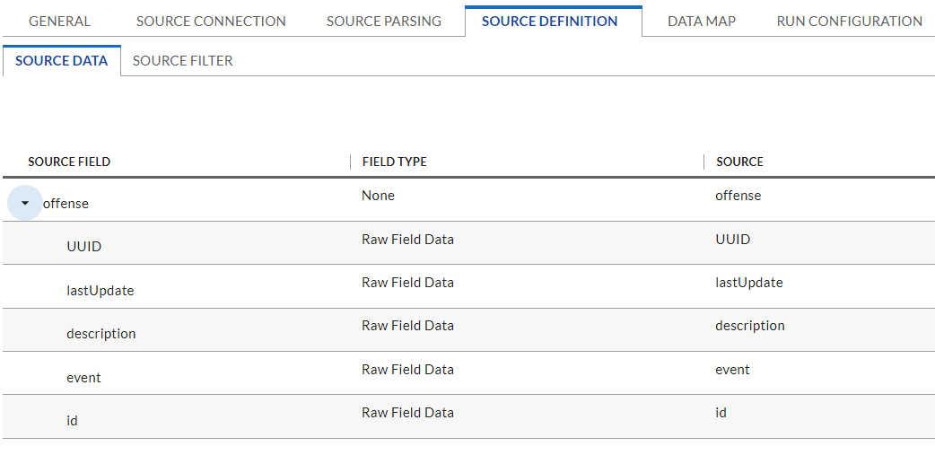
Map the Source Fields to the Target Fields in the Field Map sub-tab in the Data Map tab. Use Table 2‑9 for reference.
Table 2‑9 QRadar Data Feed Source Field to Destination Field Mapping
Source Field |
Destination Field |
|---|---|
UUID |
/SCA Computing Device/Enterprise Unique Identifier |
lastUpdate |
Date/Time QRadar LastUpdate |
description |
Incident Summary |
event |
Title |
id |
Incident ID (QRadar) |
In the Key Field Definition sub-tab in the Data Map tab, choose Incident ID (QRadar) as the Key Field Definition. Additionally, choose Enterprise Unique Identifier as the Key Field definition for the SCA Computing Device reference field.
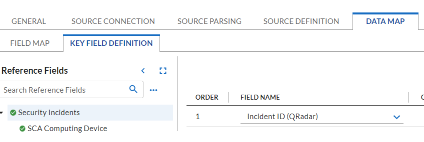
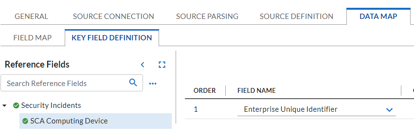
2.11.2.2.5 Create Seagate API Data Feeds
Repeat steps from Section 2.11.2.2.1 to add the Data Feed for Seagate drive firmware attestation and firmware hash data with the following modifications:
Enter Seagate Attestation Feed in the Name field section of the General tab. In the Feed Information section of the same tab, select Seagate Firmware Attestation from the Target Application pull-down menu.
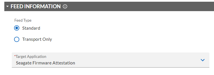
In the Transport Configuration section of Source Settings, choose the Seagate script from the project repository.
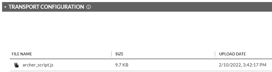
In the Custom Parameters section of Source Connection tab, enter the PMCS URL and the filter value of seagate.fw.attestation.
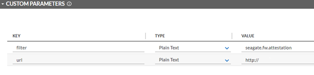
In the Source Data section of the Source Definition tab, upload the example Seagate Firmware Attestation XML response file.
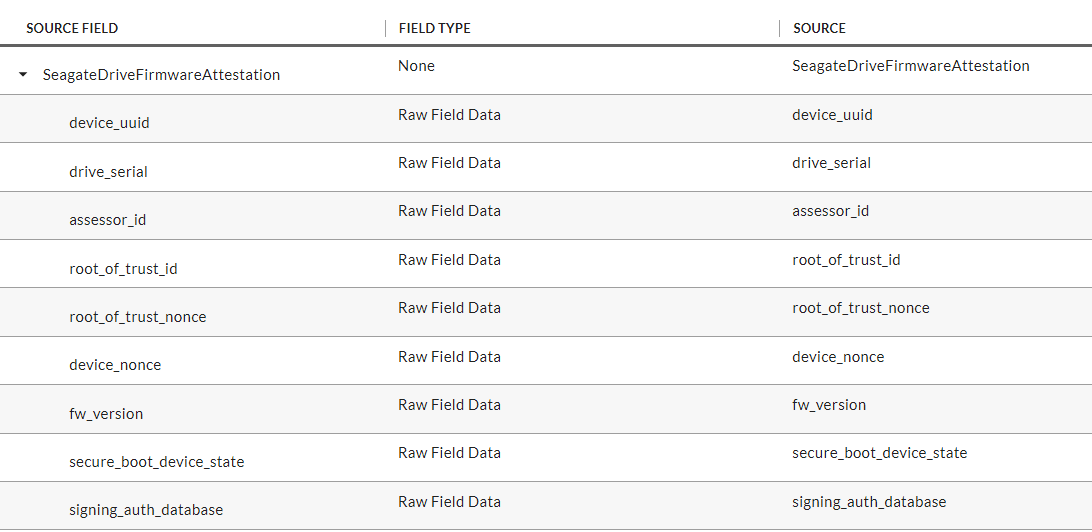
Map the Source Fields to the Target Fields and the Field Map sub-tab in the Data Map tab. Use Table 2‑10 for reference.
Table 2‑10 Seagate Drive Data Feed Field Mapping
Source Field |
Destination Field |
|---|---|
drive_serial |
/Seagate Drive Serial/Serial |
assessor_id |
Assessor Identifier |
root_of_trust_id |
Root of Trust Identifier |
root_of_trust_nonce |
Root of Trust Nonce |
device_nonce |
Device Nonce |
fw_version |
Firmware Version |
secure_boot_device_state |
Secure Boot Device State |
signing_auth_database |
Signing Auth Database |
In the Key Field Definition tab within the Data Map tab, select Serial in the pull-down Field Name column.
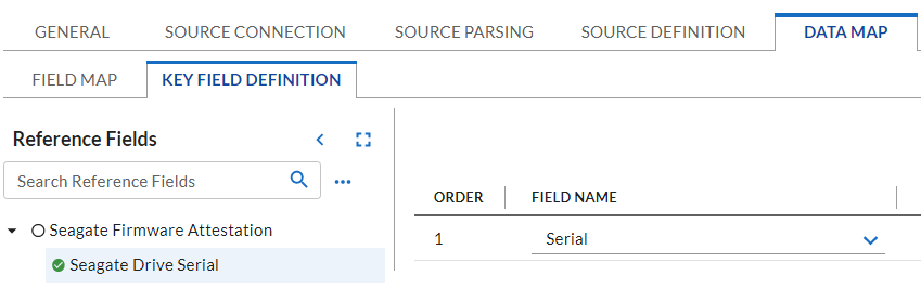
Save the new Data Feed.
Repeat the procedures in this section to create a Data Feed that will collect the Seagate drive firmware hash values. Note that this Data Feed will target the Seagate Firmware Hash application.
2.11.2.3 Create the Dashboard
Create a new report by clicking Reports in the administrative console and Add New.

Select the Devices application that was created in the preceding steps—in this case, Enterprise Computing Devices.
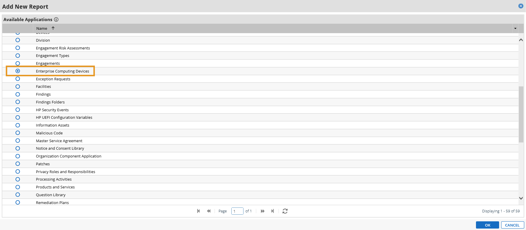
Click the Statistics Mode option. In the Fields to Display section, select Operational Use Validation Status and remove the default selections.
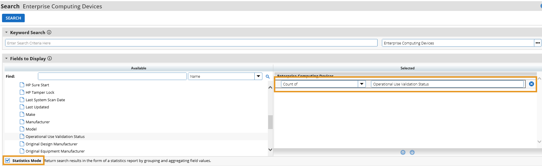
In the Filters section, select Operational Use Validation Status for Field to Evaluate, Equals for Operator, and Policy violation for Value(s).

Select Display Totals in the Display Options section.
Select Chart Only and click Save and supply a unique name for the report.
Create a new iView by navigating to Workspaces and Dashboards > Global iViews in the administrative menu. Click Add New.
In the iView Types section, select Report and click OK.
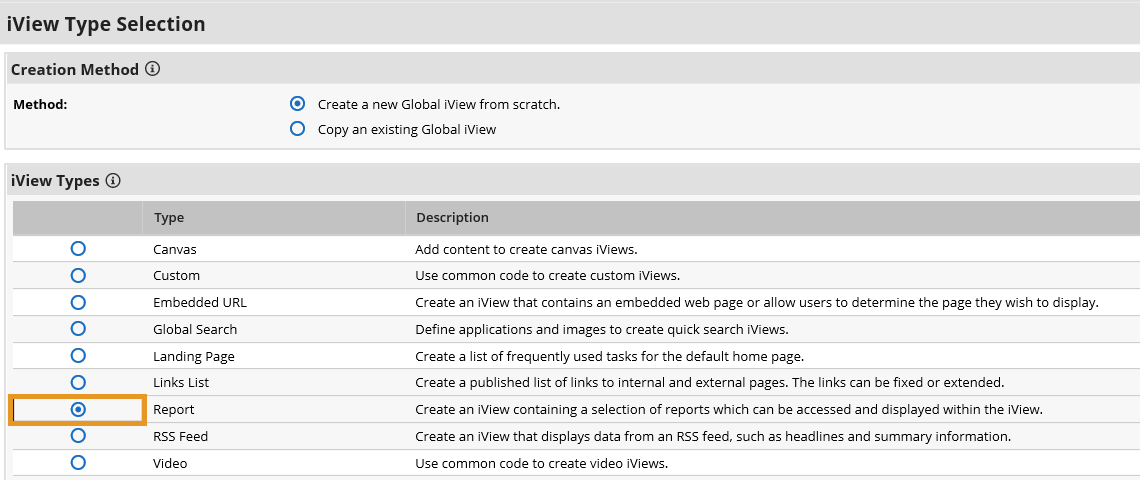
In the General Information section, supply a name and a folder to store the new iView.
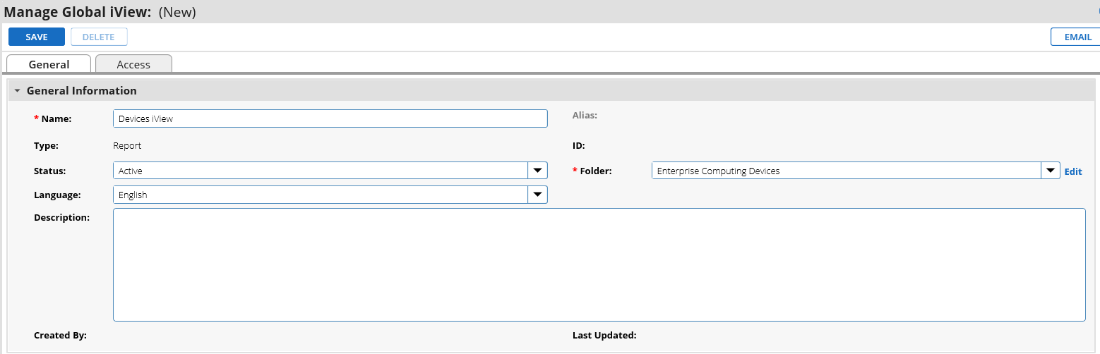
In the Options section, choose the report that was created in the preceding steps and save the iView.
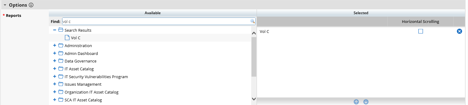
Create a new Dashboard by navigating to Workspaces and Dashboards > Dashboards in the administration menu. Click Add New.
Select Create a new Dashboard from scratch and click OK.
In the General tab, supply a name for the Dashboard.
In the Layout tab, click Select iViews. Choose Select from Global iView Library for the Creation Method. Choose the iView created in the preceding steps and click OK.
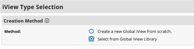
The selected iView will appear in the layout. Save the Dashboard.
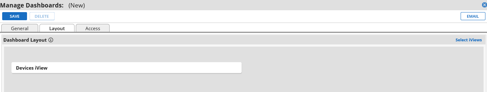
Open the solution workspace by navigating to Workspaces and Dashboards > Workspaces in the administration menu. In the Dashboards tab, choose the Dashboard created in the preceding steps by clicking Select Dashboards.
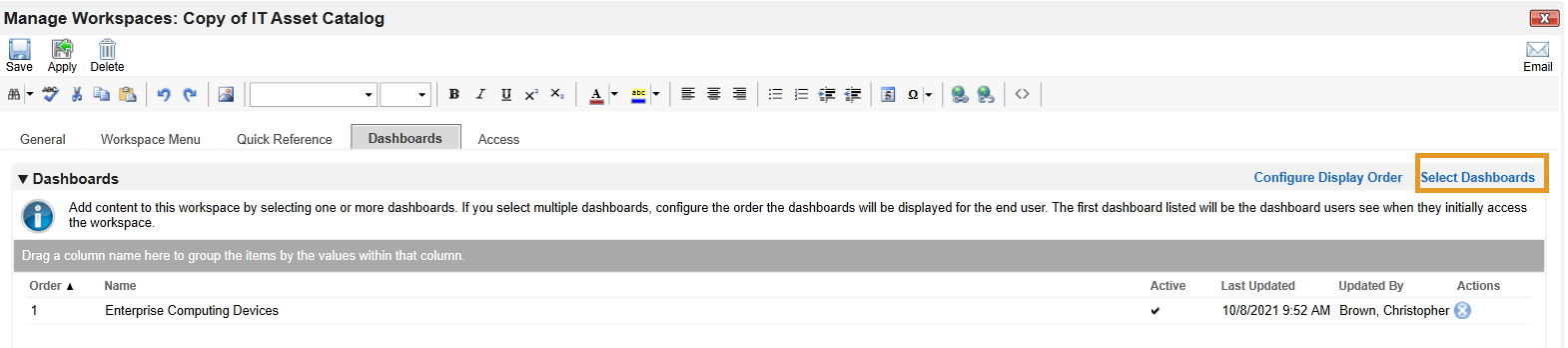
Save the workspace. At this point, the new Dashboard will appear as part of the workspace. For further customization options, refer to the RSA website.
Repeat the steps in this section to create a report that tracks platform integrity issues that are detected from the following sources:
Platform |
Archer Application |
Archer Data Field |
|---|---|---|
Eclypsium Analytic Platform |
Enterprise Computing Devices |
Eclypsium Integrity Scan Status |
HP Inc |
HP UEFI Configuration Variables |
HP Inc BIOS Configuration Status |
Seagate |
Seagate Firmware Hash |
Firmware Hash Status |
2.11.3 IBM QRadar Integrations
The following sections describe how to integrate Dell and HP Inc. laptops with QRadar so that the laptops transmit continuous monitoring event logs to the QRadar console.
2.11.3.1 Dell and HP Inc. Laptops
Perform the prerequisite steps in Section 2.2.1.3, then on each target laptop:
Ensure Remote Event Log Management is enabled for each laptop.
(Optional) In the QRadar console, create a new log source group which may be desirable to help organize target laptops. In our demonstration, we created a group for each manufacturer.
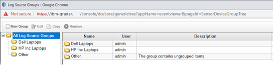
Create a new log source for the WinCollect Agent (see Section 2.10.1). Note that when configuring the Log Source parameters, a Windows account is required to retrieve the relevant security event. This demonstration created a domain account with privileges limited to the scope of this capability (Manage auditing and security log permission enabled).
2.11.3.2 IBM QRadar
The section describes the procedures that will create Offenses generated from detected laptop platform integrity security events. Additionally, it also describes an API key that is used to access the QRadar REST API. The key is used as input to Section 2.11.2.2.4.
2.11.3.2.1 Create Custom Event Property (UUID)
This property uses a regular expression (regex) to identify universally unique identifiers (UUIDs) that are embedded in Windows 10 Event Logs that are sent from laptops when a platform integrity issue is detected.
In the QRadar console, navigate to Admin > Custom Event Properties. Click Add and a new window pops up. In the Test Field, paste in the example event log.
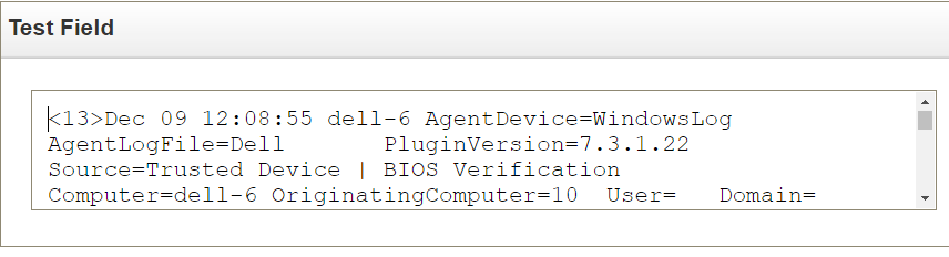
In the Property Definition section, select New Property and enter UUID for Supply Chain. Check Enable for use in Rules, Forwarding Profiles and Search Indexing.
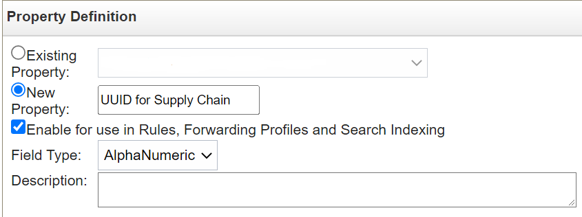
In the Property Expression Definition section, ensure Enabled is checked. In the Log Source Type pull-down, select Microsoft Windows Security Event Log and select All in the Log Source pull-down. Select the Category radio button. Choose Any in both the High Level Category and Low Level Category pull-downs. In the Regex field, insert the value below.
([0-9a-fA-F]{8}\-[0-9a-fA-F]{4}\-[0-9a-fA-F]{4}\-[0-9a-fA-F]{4}\-[0-9a-fA-F]{12})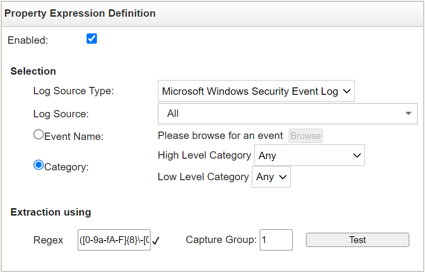
Click the Test button. If successful, a message will appear that the expression has been highlighted in the payload. Click the Save button.
2.11.3.2.2 Create Custom Event Properties (Security Events)
This section describes how to create filters that will identify the individual HP Inc. and Dell platform integrity events that have been detected and reported to QRadar. Use Table 2‑11 as a guide. We used existing QRadar Categories which group manufacturer security events. These procedures also require an example of the security event payload that is created on the manufacturer’s laptop when a platform integrity issue is detected. For HP Inc laptops, the payloads are generated by custom PowerShell scripts which consume the output from the CMSL Get-HPFirmwareAuditLog command. Dell security event payloads are generated directly by the Dell Trusted Devices platform.
Table 2‑11 QRadar Security Event Mapping
QRadar Category |
Manufacturer Event Category |
Manufacturer Event Value |
|---|---|---|
Custom Policy 1 |
HP_Sure_Start |
Integrity violation |
Custom Policy 2 |
HP_Sure_Start |
Policy violation |
Custom Policy 3 |
HP_Sure_Start |
Recovery |
Custom Policy 4 |
HP_Sure_Start |
Revert to default |
Custom Policy 5 |
Sys_Config |
Policy violation |
Custom Policy 6 |
HP_Sure_Start |
Attack mitigation |
Custom Policy 7 |
HP_Sure_Start |
SMM execution halted |
Custom Policy 8 |
Secure_Platform |
Management Attack mitigation |
Custom Policy 9 |
HP_Sure_Recover |
Recovery initiated |
Custom User 1 |
HP_Sure_Recover |
Recovery success |
Custom User 2 |
HP_Sure_Recover |
Recovery failure |
Custom User 3 |
HP_Sure_Start |
Illegal DMA Blocked |
Custom User 4 |
HP_Sure_Admin |
Power off due to failure authentication |
Custom User 5 |
HP_Sure_Admin |
WMI blocked due to failed authentication |
Custom User 6 |
HP_Sure_Start |
EpSC execution halted |
Custom User 7 |
HP_TamperLock |
Cover removed |
Custom User 8 |
HP_TamperLock |
TPM cleared based on Policy |
Custom User Medium |
Dell Laptop DTD BIOS Violation |
N/A |
In the QRadar console, navigate to Admin > Custom Event Properties. Click Add and a new window pops up. In the Test Field, paste in the example event payload. In the screenshots below, we are using a payload which includes a HP_Sure_Start Policy violation.
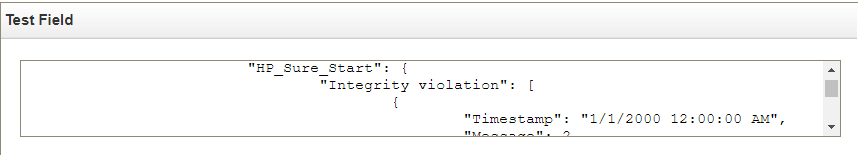
In the Property Definition, select New Property. Name the new property “[Event Category] [Event Value]”. Check Enable for use in Rules, Forwarding Profiles and Search Indexing.
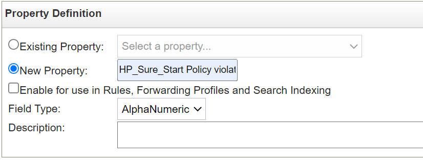
In the Property Expression Definition section, make sure Enabled is checked. In Log Source Type, select Microsoft Windows Security Event Log. In Log Source select All. Select the Event Name radio button.
Click Browse and search for “Application Information Event” (with quotes) in the QID/Name field. Select it and click OK.
Select Extraction using JSON Keypath. “HP_Sure_Start Policy violation” will look like the following as an example:
/"data"/"Events"/"HP_Sure_Start"/"Policy violation"[]
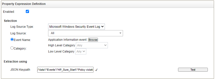
Click the Test button. If successful, the security event is found in the Test Field. Click Save.
Continue the process for all events listed in Table 2‑11.
2.11.3.2.3 Create QRadar Rules
In the QRadar console, click Log Activity. Select Rules > Rules then Actions > New Rule.
Ensure Events is selected, then click Next.
Enter a name for the rule. We used the following pattern: “[Event Category] [Event Value] rule”.
In the rules editor, search for “event matches this AQL filte query”. Click the “this” hyperlink to launch the Ariel Query Language (AQL) filter query. Enter the query below and click Submit.
"Event ID"=3001Create another criteria by using “when the event matches this search filter”. Click “this search filter” and locate the matching Custom Property. Select “is not N/A” and click Add. Click Submit.
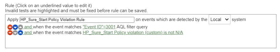
(Optional) Make the rule part of a group to organize platform integrity offenses. We created a custom group named “Supply Chain Security Event”.
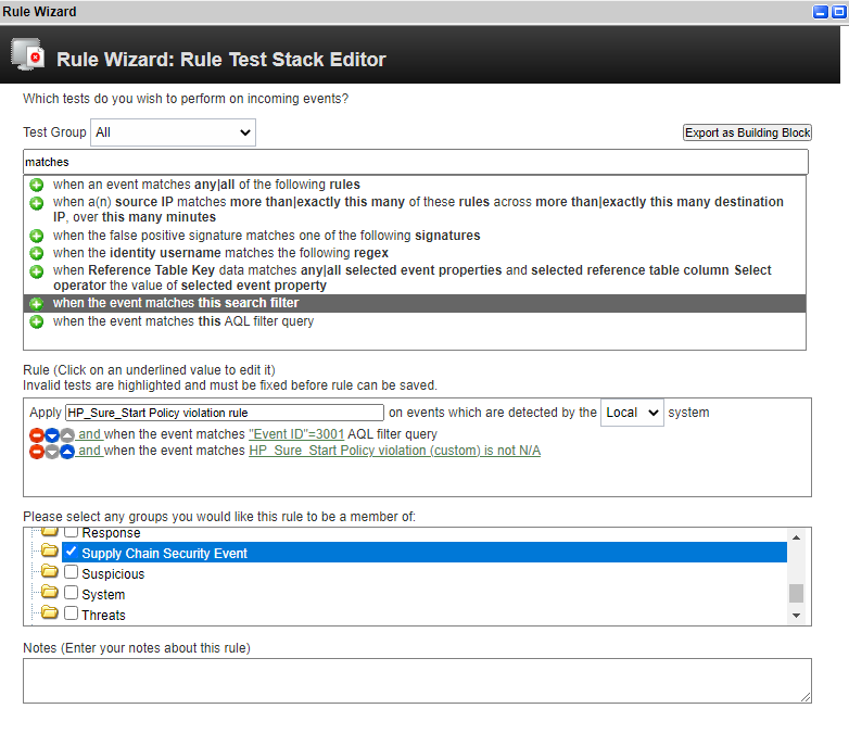
Click Next. In the Rule Response section, select Dispatch New Event. Create an Event Name and Event Description following the same pattern as above.
In the Event Details section, select the High-Level Category of “User Defined” and choose the Low-Level Category noted in Table 2‑11.
Check “Ensure the dispatched event is part of an offense”. Index offense based on “UUID for Supply Chain” in the pull-down menu.
In the Offense Naming section, select the second option (replace).
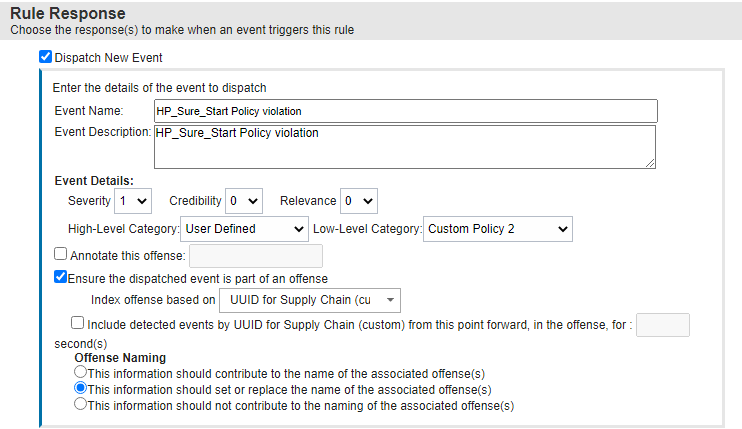
Click Finish. The new rule will appear in the Offenses > Rules tab.
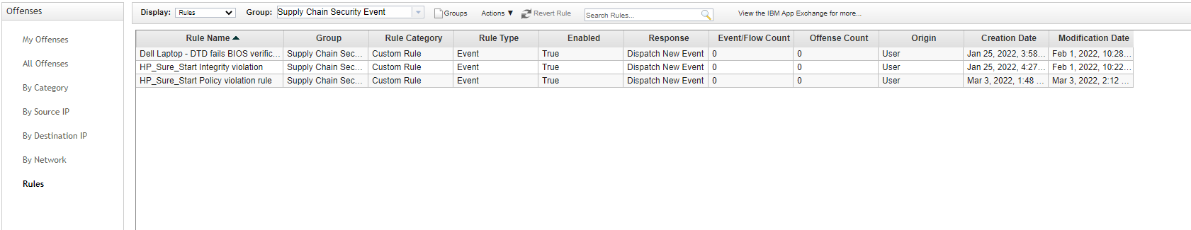
Repeat this section for every security event listed in Table 2‑11.
2.11.3.2.4 Create an Authorized Service Token
In the administration console, click Authorized Services, then Add New. Enter an Authorized Service Label and appropriate Security Profile and User Role for your environment. Click Save.
The QRadar console will display the following dialog. Click the “eye” to reveal the secret token. Store the token securely.
3 Operational Considerations
This section describes the execution steps of an IT administrator assigned to the acceptance testing or monitoring of computing devices during their operational lifecycle. Each subsection restates the scenarios from the project description, but this prototype demonstration does not address each scenario in totality
Create an environment as described in Section 2 before attempting to use the proof-of-concept tools below.
3.1 Scenario 2: Verification of Components During Acceptance Testing
In this scenario, an IT administrator receives a computing device through nonverifiable channels (e.g., off the shelf at a retailer) and wishes to confirm its provenance and authenticity to establish an authoritative asset inventory as part of an asset management program.
The general execution steps are as follows:
As part of the acceptance testing process, the IT administrator uses tools to extract or obtain the verifiable platform artifact associated with the computing device.
The IT administrator verifies the provenance of the device’s hardware components by validating the source and authenticity of the artifact.
The IT administrator validates the verifiable artifact by interrogating the device to obtain platform attributes that can be compared against those listed in the artifact.
The computing device is provisioned into the physical asset management system and is associated with a unique enterprise identifier. If the administrator updates the configuration of the platform (e.g., adding hardware components, updating firmware), then the administrator might create new platform artifacts to establish a new baseline.
3.1.1 Technology Configurations
3.1.1.1 Configure the HIRS ACA
Before running the acceptance test on Dell and HP Inc. laptops, the HIRS ACA must be configured with the target laptop’s platform attribute certificate and any trust chains associated with the platform attribute certificate and endorsement credential.
On the HIRS ACA web portal, under the Configuration panel, select Policy.
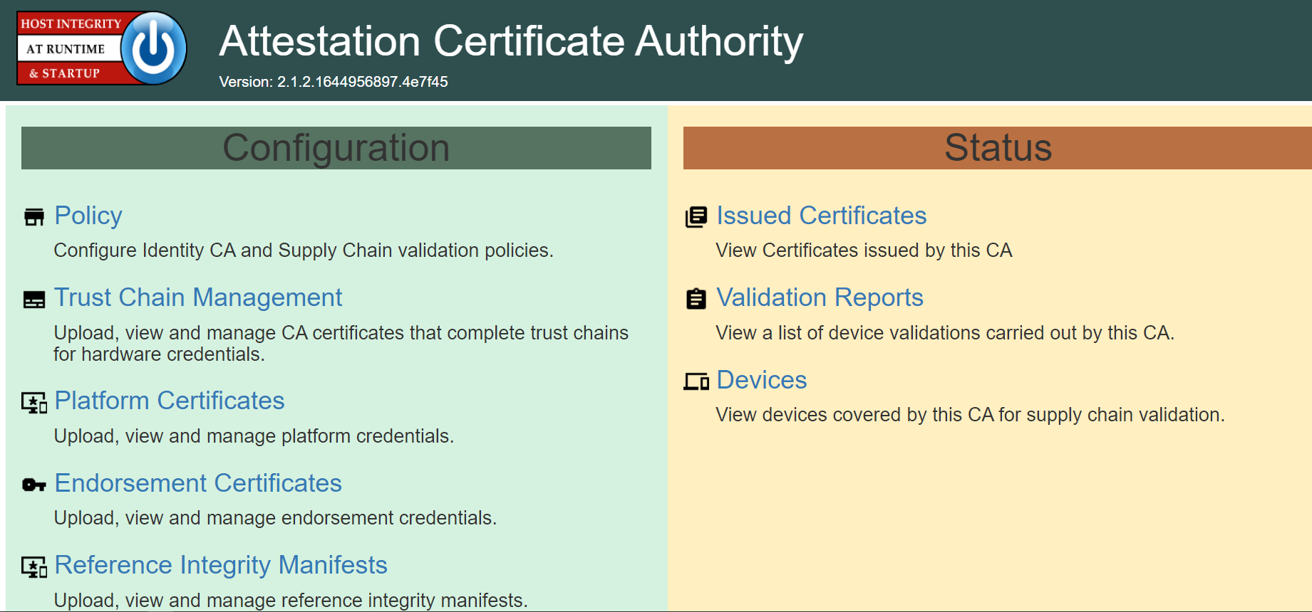
For this prototype demonstration, make sure the following policy options are set as listed in the table below.
Policy Option
Setting
Endorsement Credential Validation
Enabled
Platform Credential Validation
Enabled
Platform Attribute Credential Validation
Enabled
Firmware Validation
Disabled
Ignore IMA PCR Entry
Disabled
Ignore TBOOT PCRs Entry
Disabled
Ignore GPT PCRs Entry
Disabled
Ignore OS Events
Disabled
Generate Attestation Certificate
Enabled
Attestation Certificate Validity period
Disabled
Attestation Certificate Renewal period
Disabled
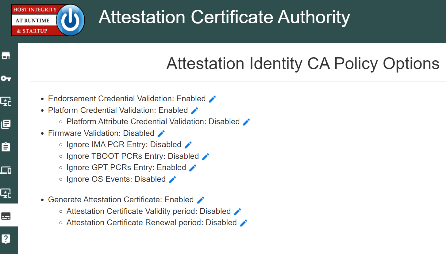
Upload the trust chain certificates by navigating to the Configuration panel, then selecting Trust Chain Management.
Select the icon beside Import Trust Chain CA Certificates.
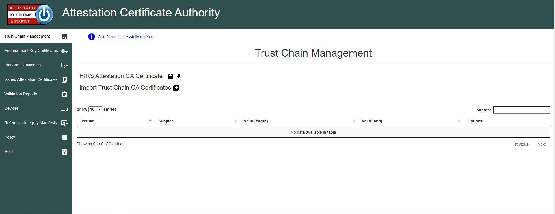
Select Choose Files.
Select the Trust Chain Certificate from the local computer. In the example below, the .crt file is named PCTestCA.example.com. Optionally, select multiple certificates if your implementation includes computing devices from distinct manufacturers. Click Open.
Select Save.
The Trust Chain certificate should appear under the Trust Chain Management tab. Repeat this process for all root and intermediate certificates.
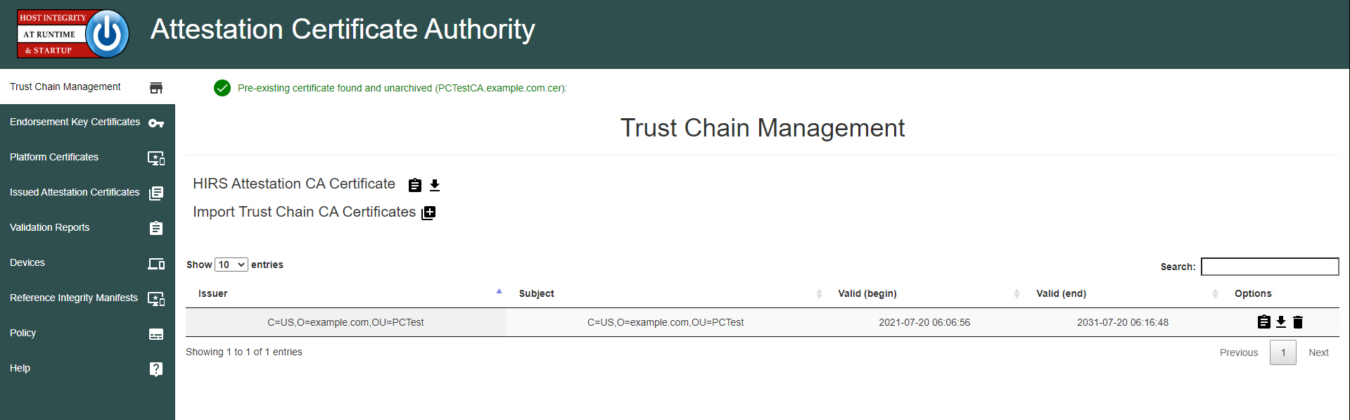
Update the Platform Attribute certificates by navigating to the Configurations panel, then selecting Platform Certificates.
Select the icon beside Import Platform Certificates.
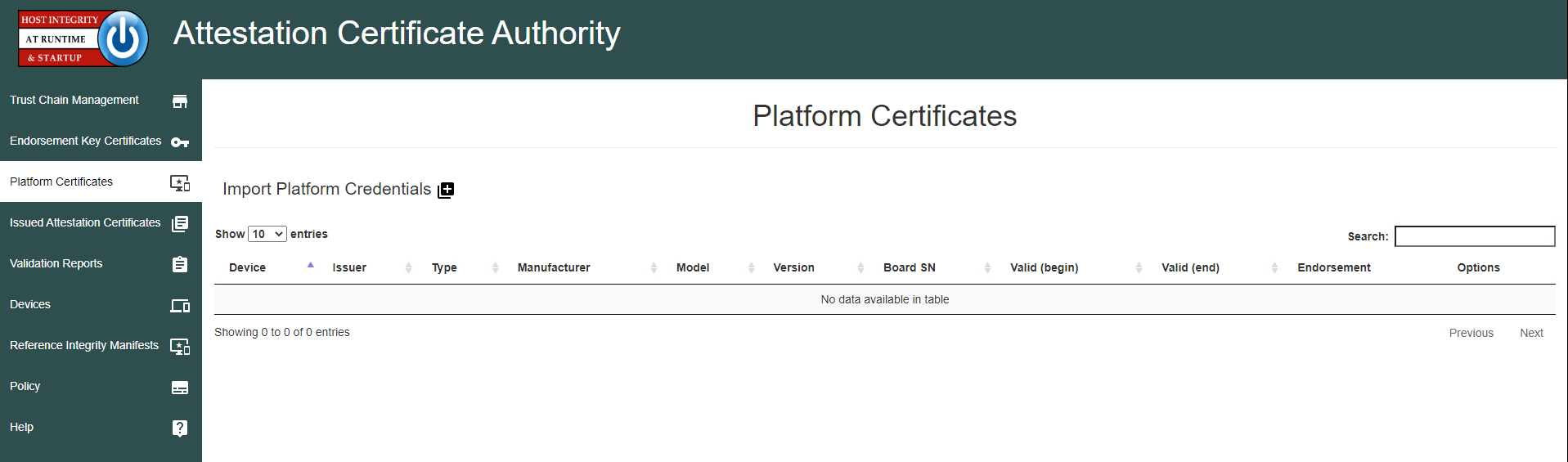
Select Choose Files.
Select the Platform Certificate from the local computer. In the example below, the .crt file is named PlatformCredential_1. Select the file and click Open.
Select Save.
The Platform certificate should appear under the Platform Certificates tab.
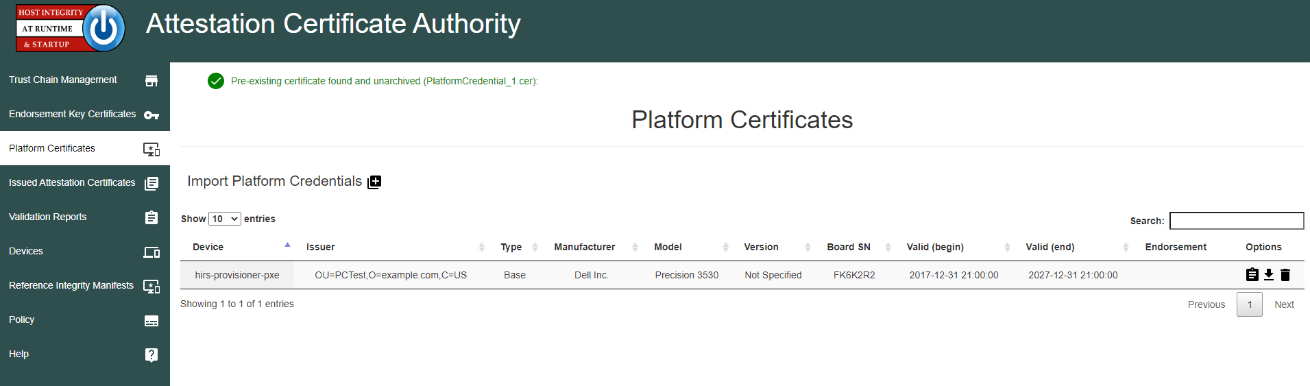
Upload the Endorsement Key certificate by navigating to the Configuration panel, then selecting Endorsement Certificates.
Select the icon beside Import Endorsement Key Certificates.
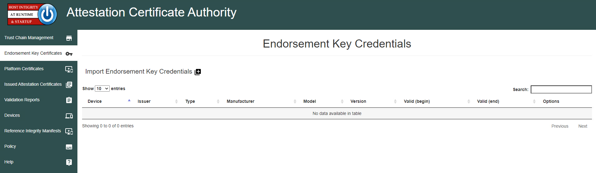
Select Choose Files.
Select the Endorsement Credential from the local computer. For this project, the .crt file is EndorsementCredential_17751206596310784982788. Select the file and click Open.
Select Save.
The Endorsement Key certificate should appear under the Endorsement Key Credentials tab.
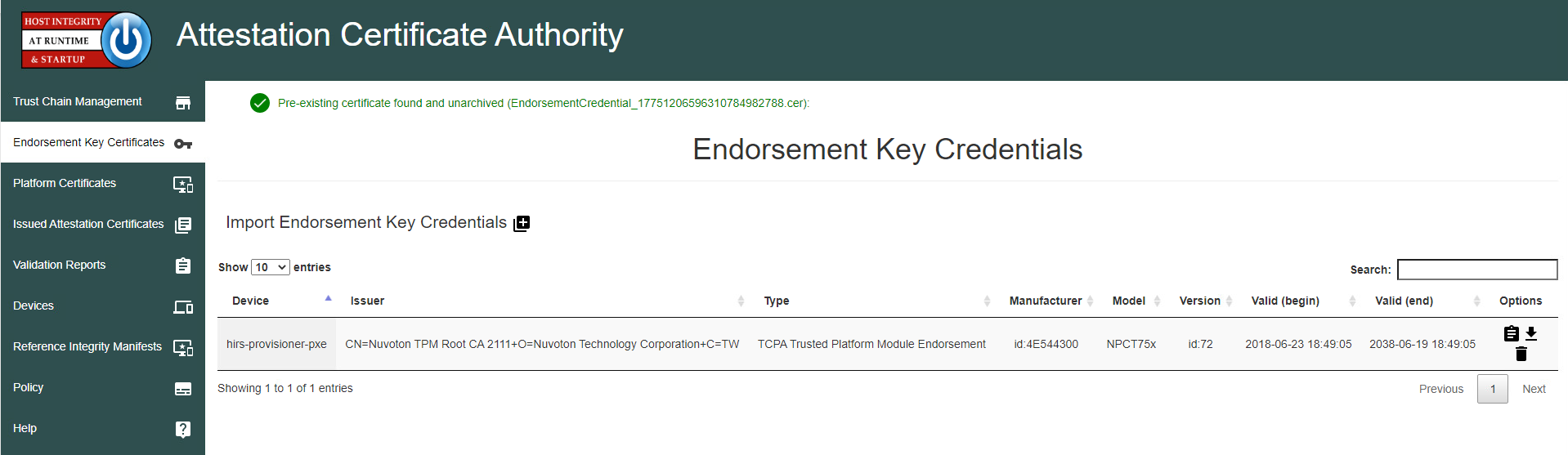
3.1.1.2 Dell and HP Inc. Laptops
Boot the target laptop into the CentOS 7 acceptance testing environment via iPXE. This typically requires a one-time boot execution to prevent the laptop from loading the native OS. Consult the manufacturer’s documentation for the appropriate steps. Choose HIRS Provisioner Live from the iPXE boot menu.
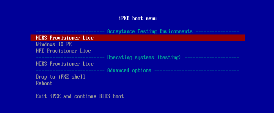
Once the live environment has loaded, log in as a user with root privileges. Run the provision.sh script. The script will attempt to:
Change the hostname of the live environment. This assists the administrator in locating the target machine in the Eclypsium console.
Run the Eclypsium scanner and submit results to the Eclypsium Analytic cloud platform.
Run the HIRS provisioning script. If successful, post the results to the PMCS.
The script will exit at any point an error is detected. Refer to the comments in the script to set this up in your own environment. Up-to-date information related to debugging the HIRS provisioning process can be found on the project site.
3.1.1.3 Intel-Contributed Laptops
The Auto Verify tool is central to scenario 2 acceptance testing. The tool compares the Direct Platform Data (DPD), allowing the customer to identify certain system changes from the time of manufacturing to the time of first boot. Install the Auto Verify Tool on the target system before attempting to execute the steps in this section.
The DPD files and platform certificate files for the target laptop are available from Intel’s Transparent Supply Chain demo page, https://tsc.intel.com. Work with your Intel representative to obtain credentials for your organization.
3.1.1.3.1 Download DPD File and Platform Certificate
Authenticate to the Intel TSC Client Demo portal page.
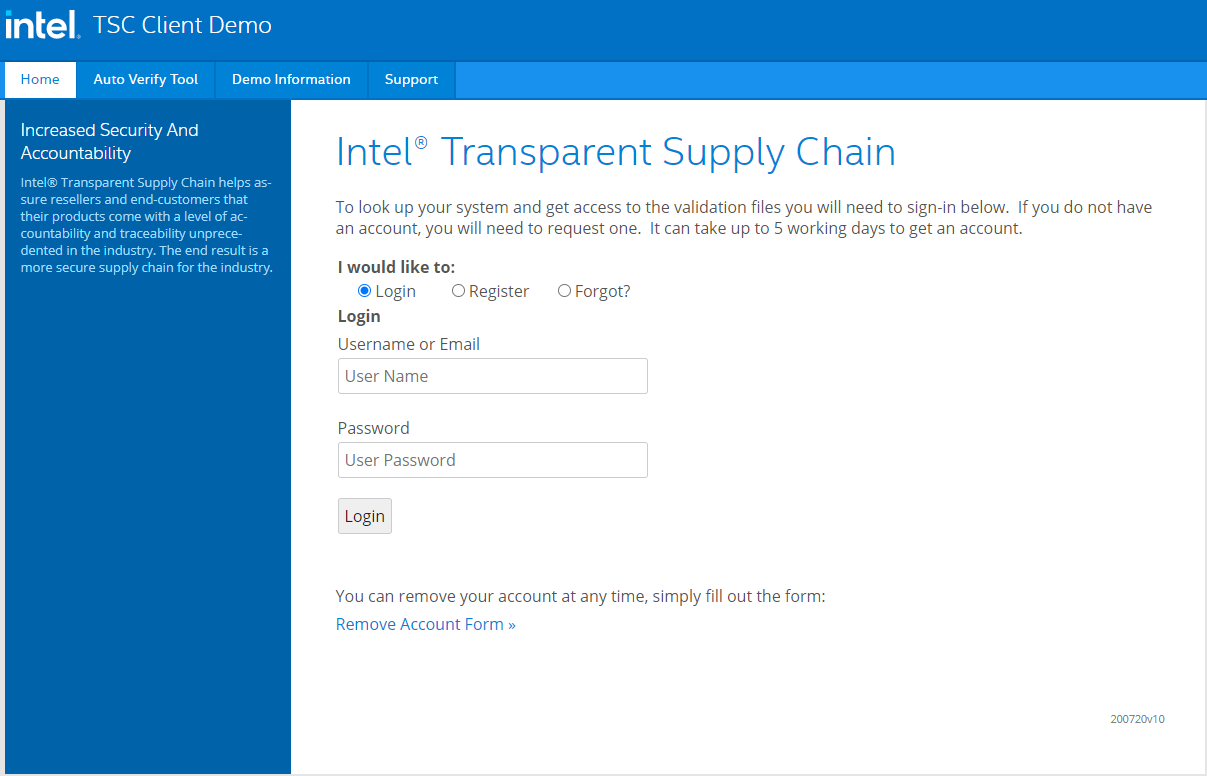
Enter the serial number of the Intel laptop. Select Search.
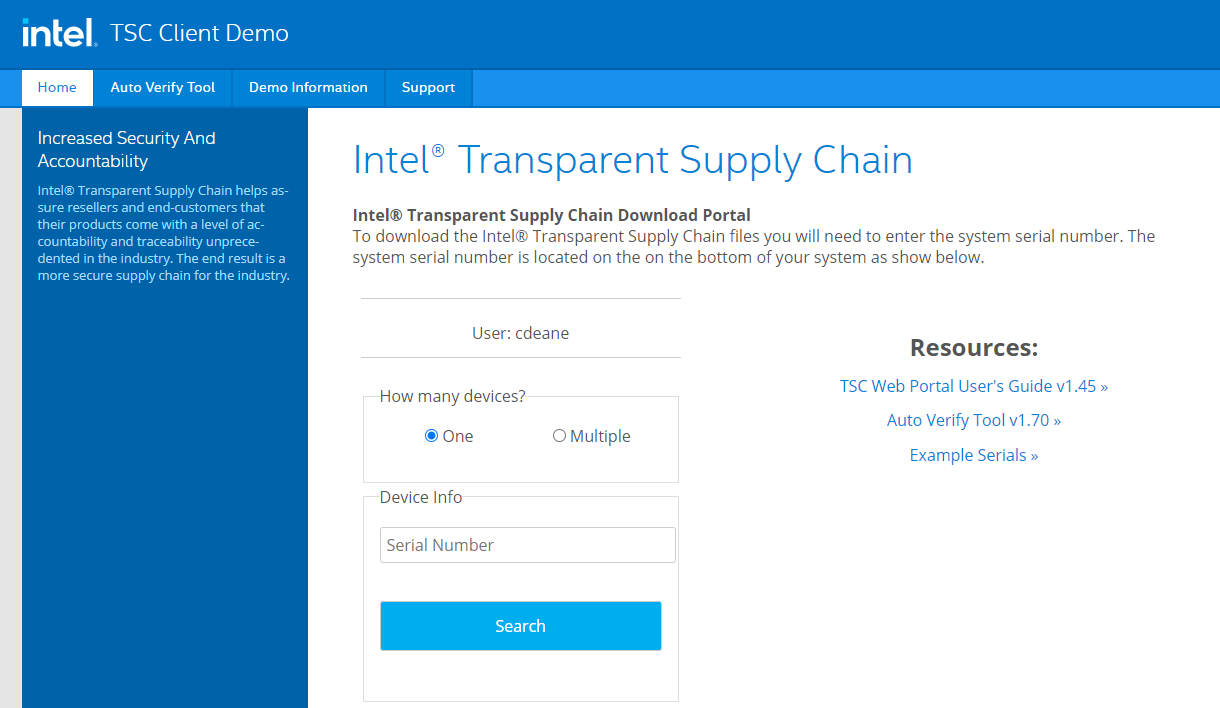
Download the zip file containing the DPD files and platform certificate. Save and unzip the file on the target laptop. These files will be used with the Auto Verify tool to determine if any components have been changed.
Launch the Auto Verify Tool.
Click the Scan System button.
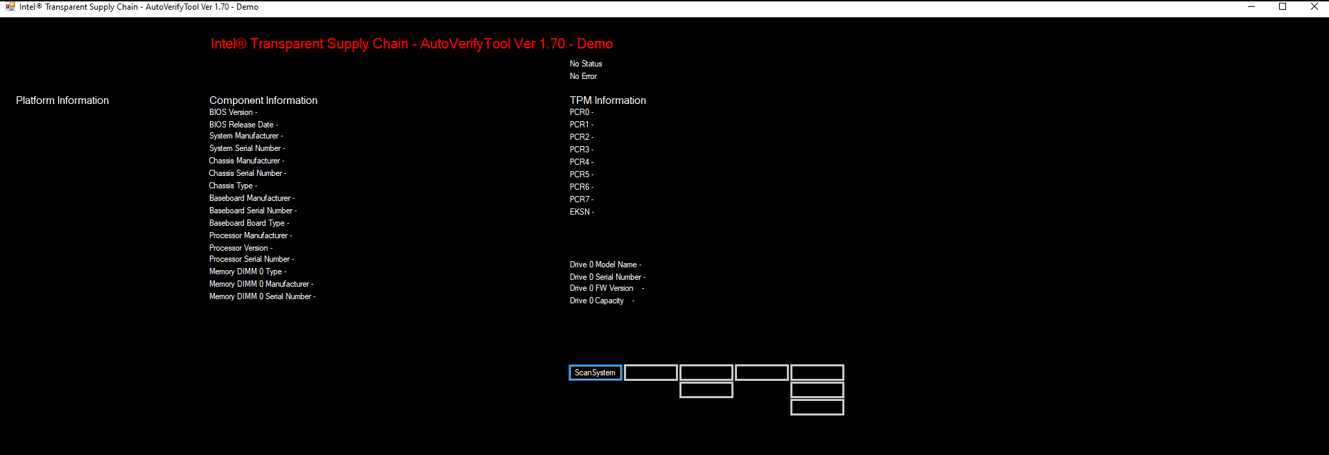
The Auto Verify Tool should populate the Component Information entries with the platform details of the computer. To compare the data to the DPD file stored on the local computer, click ReadFile.
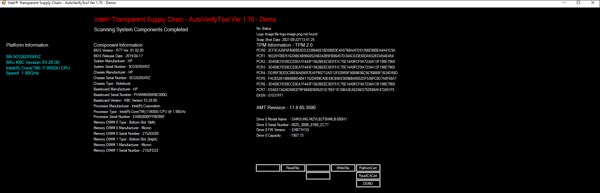
Navigate to the downloaded DPD file and select Open.
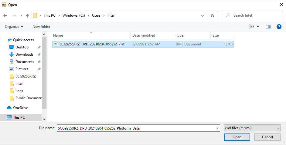
Next, click the Compare button.
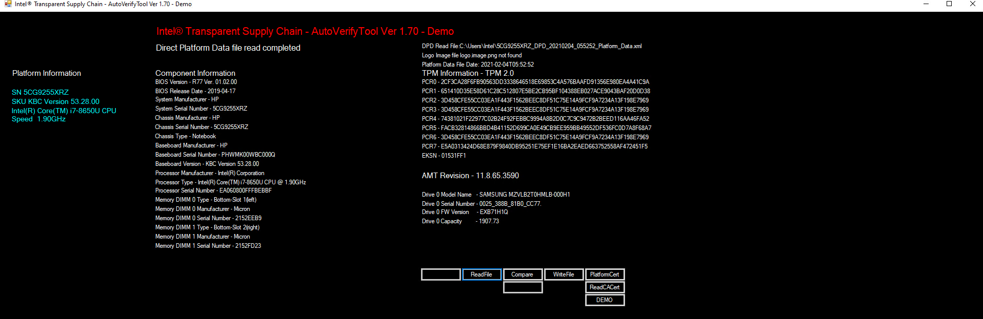
If no changes have been made, the Auto Verify tool should output a green message that says, “No Component Changes have been detected.” To compare the certificate file, click the PlatformCert button.
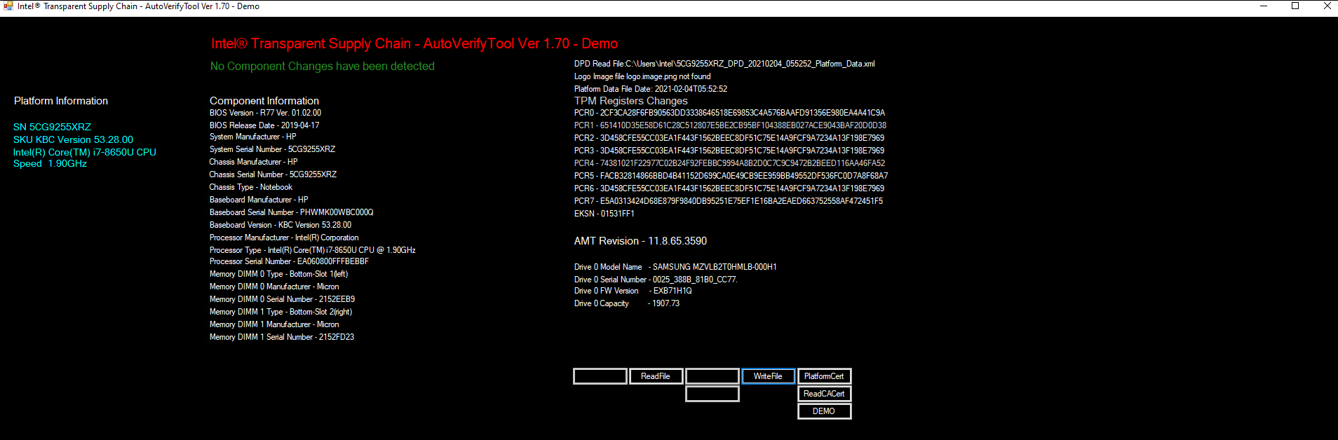
Navigate to the location of the platform certificate and select Open.
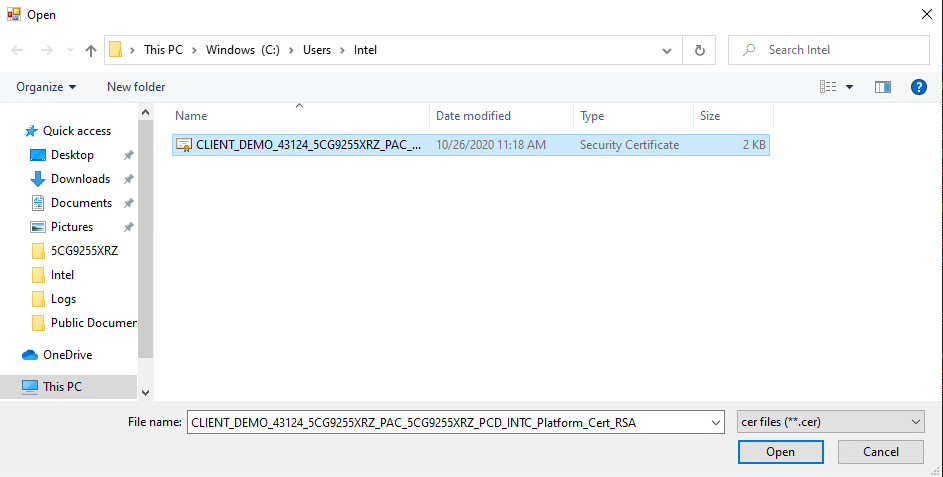
If the certificate matches the certificate that the AutoVerify tool detected, the tool will output another green message that reads “Platform Certificate Matches.”
3.1.1.4 HPE Servers
Boot the target HPE server into the CentOS 8 acceptance testing environment via iPXE. This requires a one-time boot execution to prevent the server from loading the native OS. Press F11 in the POST screen after a server reboot to access the one-time boot menu and choose the appropriate network interface card. Then choose HPE Provisioner Live from the iPXE boot menu.
Once the live environment has loaded, log in as a user with root privileges. Run the hpe_provision.sh script. The script will attempt to execute the PCVT against the verifiable artifacts stored in the image. If successful, the script posts the platform manifest to the PMCS.
The script will exit when an error is detected. Refer to the comments in the script to set this up in your own environment.
3.1.1.5 Dell Servers
Boot the target Dell server into the Windows PE acceptance testing environment via iPXE. This requires a one-time boot execution to prevent the server from loading the native OS. Press F12 in the POST screen after a server reboot to access the one-time PXE boot option and choose the appropriate network interface card. Then choose Windows 10 PE from the iPXE boot menu.
Once the live environment has loaded, log in as a user with root privileges. Run the dell-server-scv.ps1 script. The script will attempt to execute the Dell Secured Component Verification (SCV) tool against the verifiable artifacts stored on the server. If successful, the script posts the platform manifest to the PMCS.
The script will exit when an error is detected. Refer to the comments in the script to set this up in your own environment.
3.1.1.6 Intel Server
Boot the Intel Server into the CentOS 8 host OS environment. Note that for the demonstration Intel server, a network-booted acceptance testing environment was not implemented.
Once the operating system has completed booting, log in as a user with root privileges. Run the provision.sh script. The script will attempt to execute the TSCVerifyUtil against the verifiable artifacts stored on the server. If successful, the script posts the platform manifest to the PMCS.
The script will run TSCVerifyUtil again with different command arguments which directs the program to access the Seagate drive APIs. If successful, the drive attestation data and measurements are posted to the PMCS.
The script will exit when an error is detected. Refer to the comments in the script to set this up in your own environment.
3.1.2 Asset Inventory and Discovery
Organizational members with access to the enterprise database of computing devices can access a listing by authenticating to the Archer system. We have configured our instance to display only the relevant Archer solution menus. In Figure 3‑1, the administrator clicks the SCA Devices menu link to retrieve the listing.
Figure 3‑1 Archer Solution Menu
Figure 3‑2 shows a listing of all enterprise computing devices that have had their platform validated in accordance with Scenario 2. The computing device Enterprise Unique Identifier is hyperlinked and when clicked displays additional data, as described below.
Figure 3‑2 Enterprise Computing Devices Listing
Figure 3‑3 shows a representative laptop computing device that has completed the acceptance testing process by an IT administrator. In the General Information section, we have opted to display characteristics that are common across all the manufacturers in our project such as the serial number and the make of the computing device. Separately in the Associated Components section, we store and track the components from the initial manufacturer manifest. We will continue to iterate on the asset inventory user interface to surface meaningful and easily understandable information that is appropriate for individuals responsible for IT security.
Figure 3‑3 Asset Inventory Screenshot
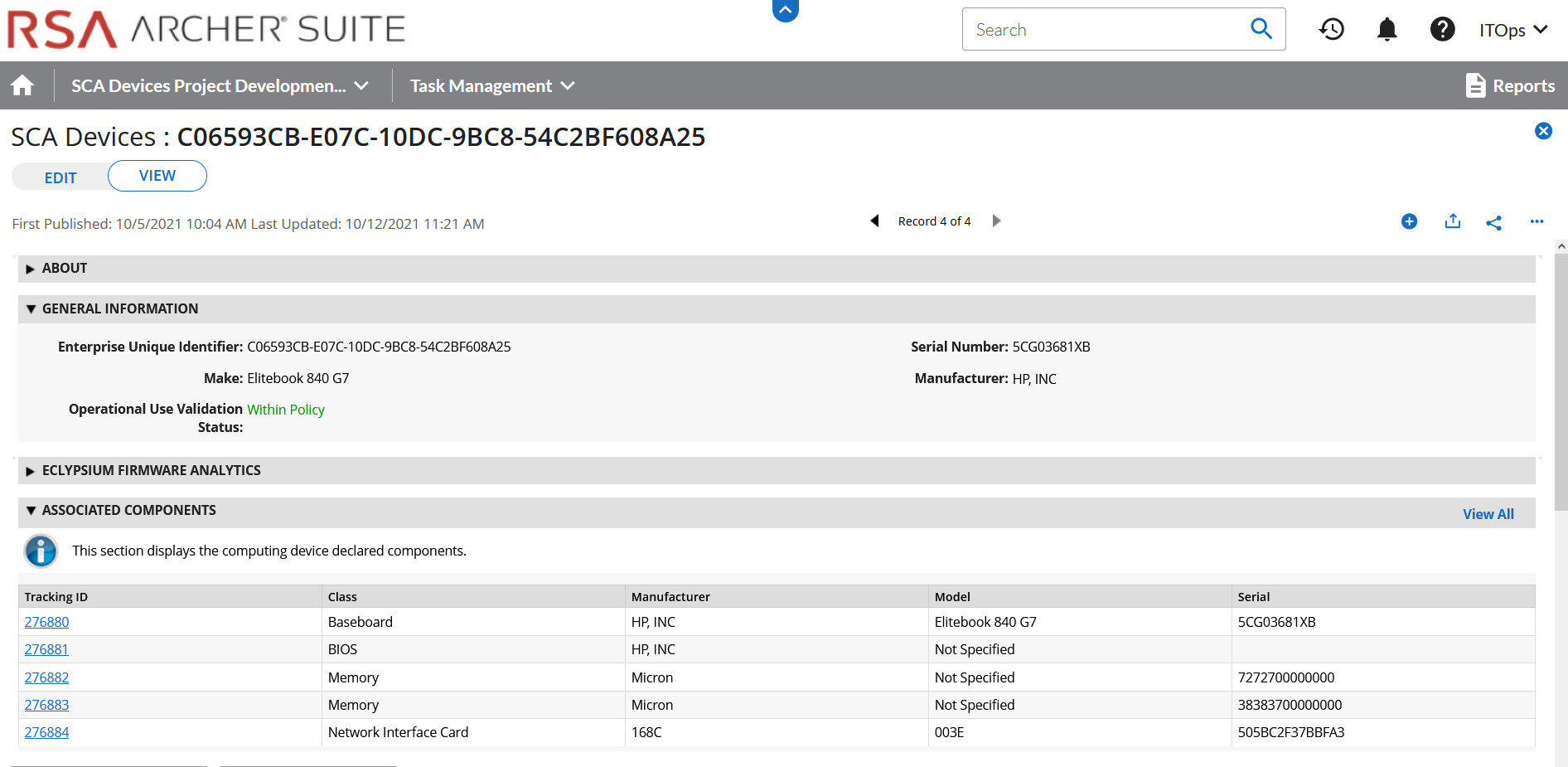
For those computing devices that support Eclypsium during acceptance testing, Archer retrieves the initial firmware data from the Eclypsium backend (cloud or on-premises) and displays it in the Eclypsium Firmware Analytics section of the record as shown in Figure 3‑4.
Figure 3‑4 Eclypsium Acceptance Testing Firmware Data
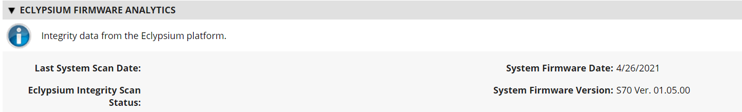
3.1.2.1 Manufacturer-Specific Attributes
As described in Volume B of this guide, this demonstration also collects manufacturer-specific platform integrity attributes in addition to the agnostic data described above. For HP Inc. laptops, BIOS configuration settings, represented as UEFI variables, are associated with the laptop in the asset inventory when available. From this perspective the security operator is able to view each variable value, description, and the recommended setting for each value. The operator is also alerted if the variable value has changed since the initial baseline (column 2), where a remediation action could be initiated.
Computing devices that use the Intel Transparent Supply Chain platform declare (if present) additional attributes such as values for the OEM, original design manufacturer (ODM), model, product name, stock keeping unit (SKU), and product family. The screenshot below is an example from a demonstration laptop asset inventory record.
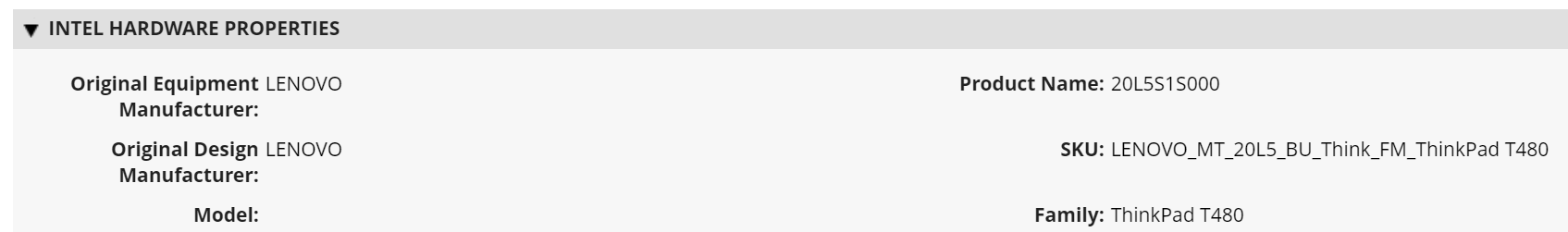
Finally, each Seagate drive asset inventory entry displays associated data from its firmware attestation and measurement capabilities. The security operator can view the currently running version of the firmware and click on the Tracking ID hyperlink for more details associated with the firmware. In the lower section, the Firmware Hash Status column informs the operator if measurement values have changed since the baseline, which may indicate an integrity issue that requires remediation.
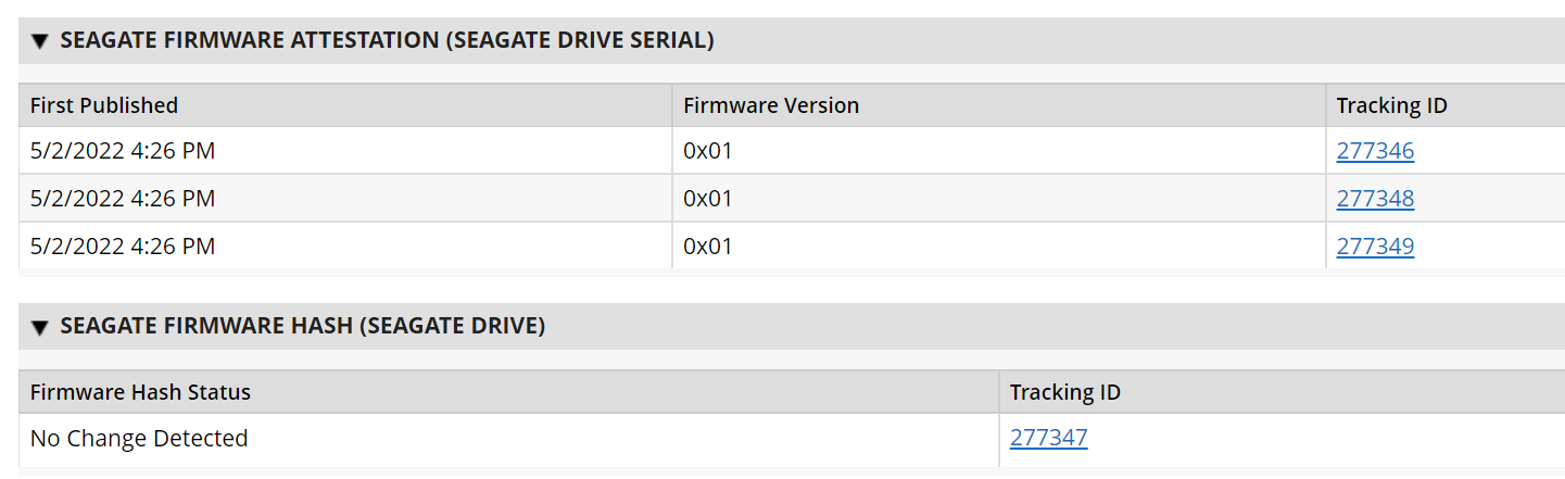
3.2 Scenario 3: Verification of Components During Use
In this scenario, the computing device has been accepted by the organization (Scenario 2) and has been provisioned for the end user. The computing device components are verified against the attributes and measurements declared by the manufacturer or purchasing organization during operational usage.
The general execution steps are as follows:
The end user takes ownership of the computing device from the IT department and uses it to perform daily work tasks within the scope of normal duties.
The computing device creates a report that attests to the platform attributes, such as device identity, hardware components, and firmware measurements that can be identified by interrogating the platform.
The attestation is consumed and validated by existing configuration management systems used by the IT organization as part of a continuous monitoring program.
The measured state of the device is maintained and updated as the authorized components of the device are being maintained and associated firmware is updated throughout the device’s operational life cycle.
Optionally, the IT administrator takes a remediation action against the computing device if it is deemed out of compliance. For example, the computing device could be restricted from accessing certain corporate network resources.
3.2.1 Technology Configurations
3.2.1.1 Monitoring Using Intel and HIRS-ACA Validation Clients
This section describes the steps that monitor for unexpected component changes using Intel TSC/HIRS-ACA tooling and Microsoft Configuration Manager capabilities.
3.2.1.1.1 Deploy Baseline
Navigate to the newly created configuration baseline located at Assets and Compliance > Overview > Compliance Settings > Configuration Baselines.
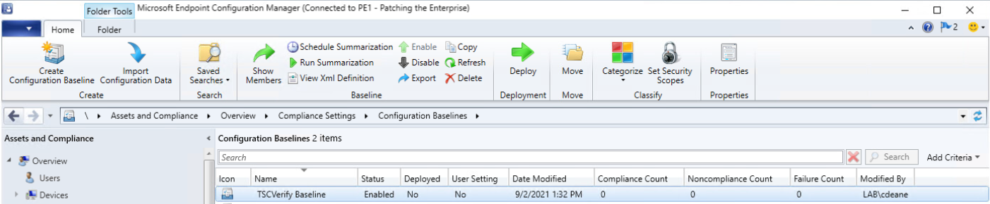
Right-click on the configuration baseline and select Deploy.
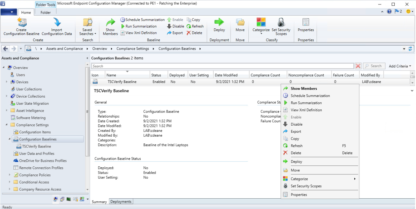
Select the device collection for the Intel TSC-supported machines. For this project, the device collection is named Intel. Select OK.
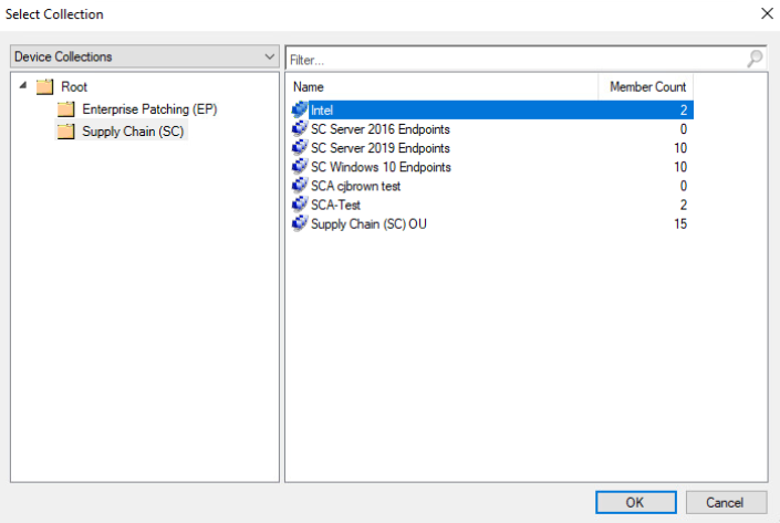
Ensure that the baseline is selected and then select the desired frequency of when to run the baseline. Select OK.
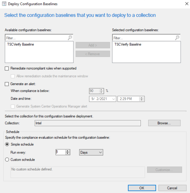
This completes the configuration for Intel TSC platform validation tools. Repeat this section to create a similar baseline for Dell and HP Inc. laptops that leverage HIRS-ACA platform validation tools.
3.2.1.2 Updating the Platform Verifiable Artifact During Operational Use
During the operational use of a computing device, a member of security operations may observe a warning in a computing device’s asset record that it is out of compliance. This could indicate that the platform has been updated but the change has not been reflected in the verifiable artifact. Archer will continue to display this warning until the verifiable artifact is updated with the new platform manifest. Figure 3‑5 illustrates this scenario.
Figure 3‑5 Out of Policy Computing Device
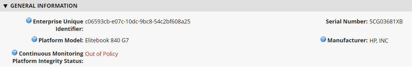
Address the policy warning by using the following procedures to create a Delta Platform Certificate on HP Inc. and Dell laptops which reflects changes in the target platform components. A Delta Platform Certificate can be created in Linux or Windows; however, this demonstration only exercises creation on the Windows platform.
Ensure the following prerequisites are met:
The administrator has installed PACCOR onto the target laptop.
A base Platform Certificate has been created and configured in the HIRS ACA. Creation of a Delta Platform Certificate is dependent on the existence of another base Platform Certificate for the same laptop.
Next, complete the following procedures to create a Delta Platform Certificate.
Open a command prompt as an Administrator on the target laptop. Change directories to the following:
<paccor install folder>\scripts\windowsCreate a directory named pc_testgen in the working directory from the previous step if it does not already exist.
Retrieve the base Platform Certificate from the HIRS ACA portal or other means. Change the filename of the Platform Certificate to holder.crt and place it into the pc_testgen directory.
Execute PACCOR’s component gathering script and capture the output with the following command.
powershell -ExecutionPolicy Bypass ./allcomponents.ps1 components.jsonThe component list needs to be manually edited to reflect added, modified, or removed components of the system. Using a JSON file editor, open the components.json file.
In the COMPONENTS object, identify the objects that represent components to be saved in the new Delta Platform Certificate. Add a STATUS field at the end of these components with a value of ADDED, MODIFIED, or REMOVED. For example, to modify the chassis serial number, create a COMPONENTS entry similar to the following.
{
   "COMPONENTS": [
      {
         "COMPONENTCLASS": {
         "COMPONENTCLASSREGISTRY": "2.23.133.18.3.1",
         "COMPONENTCLASSVALUE": "00020001"
      },
      "MANUFACTURER": "Example Manufacturer",
      "MODEL": "1",
      "SERIAL": "1234",
      "STATUS": "MODIFIED"
      }
   ]
}
Delete all other objects under COMPONENTS.
Once finished editing the components.json file, move it to the pc_testgen folder.
Using a text editor, modify the pc_certgen script header variables.
Set the ekcert variable to point to holder.crt from step 3.
Set the componentlist variable to point to components.json from step 5.
Change the value of serialnumber to 0002.
If you have a specific signing key and cert, move those files to pc_testgen as well and update the sigkey and pcsigncert variables to point to them.
Execute the pc_certgen.ps1 script using the following command:
powershell -ExecutionPolicy Bypass ./pc_certgen.ps1The resulting Delta Platform Certificate will be stored in the pc_testgen folder.
Upload the new Delta Platform Certificate to the HIRS-ACA portal.
Note that laptops that are continuously monitored with the Windows-based HIRS Provisioner will be evaluated against this new baseline.
3.2.2 Dashboards
The dashboard created in Section 2.11.2.3 attempts to consolidate and communicate potential integrity issues to the IT administrator while computing devices are in operational use. The timeliness of this information will depend on the cadence that your organization follows for updating the various data feeds from Microsoft Configuration Manager and the Eclypsium Analytic platform. This demonstration displays to the administrator if there are detected component swaps from computing devices that can leverage Intel TSC and HIRS-ACA platforms. Further, it displays any detected firmware platform integrity issues from the Eclypsium Analytic cloud and on-premises platform across all manufacturers in this prototype.
The Archer IRM dashboard should resemble the screenshots below, where a count of computing devices with potential integrity issues is displayed (Figure 3‑6 and Figure 3‑7). Your organization’s security operations team may also want to access the Eclypsium Analytic platform directly to obtain detailed information, including remediation actions, for computing devices with detected integrity issues.
Figure 3‑6 Dashboard with No Integrity Issues Detected
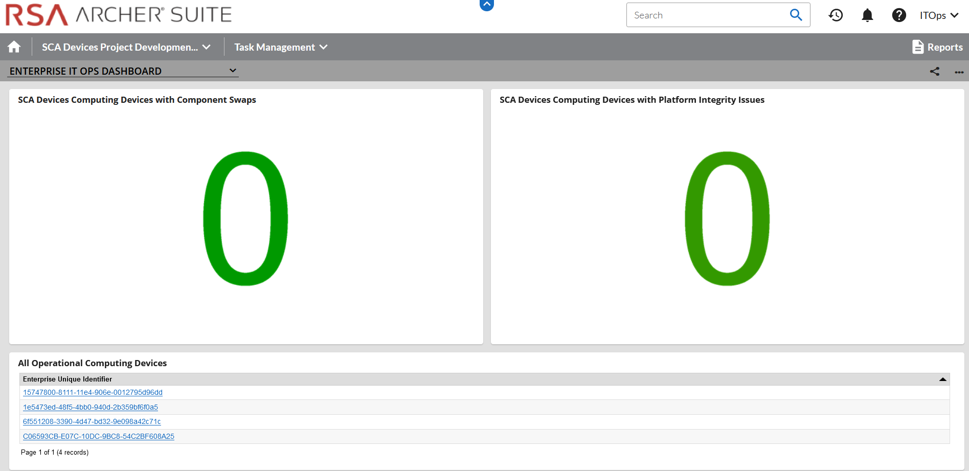
Figure 3‑7 Dashboard with Integrity Issues Detected
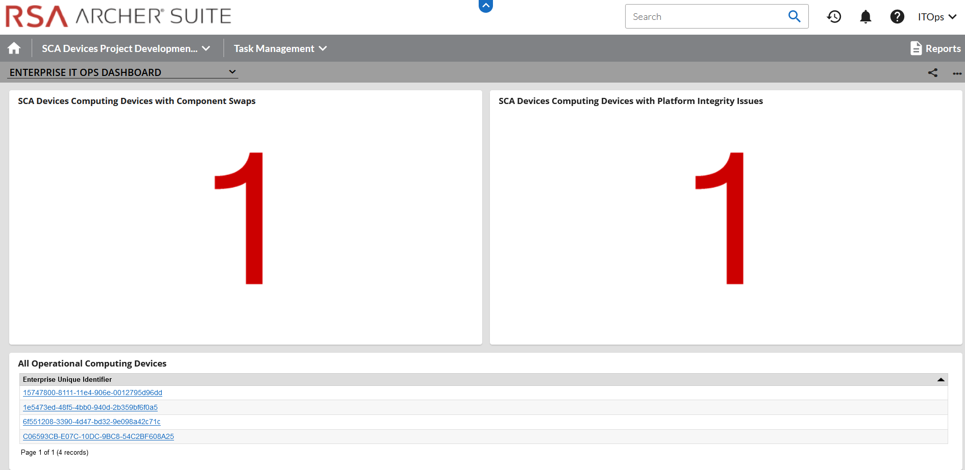
The demonstration dashboards are also capable of monitoring manufacturer-specific platform integrity datapoints. In Figure 3‑8, we show a dashboard component that captures the number of UEFI configuration parameters that have changed from the baseline values (Y-axis) for each HP Inc. computing device (X-axis).
Figure 3‑8 HP Inc. Laptop Continuous Monitoring
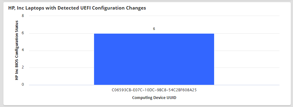
In the final dashboard component, the security operator can display the number of Seagate drives with firmware hash values that have changed since the initial acceptance testing baseline. In a production setting, it could be more useful to compare the drive measurements against known values communicated directly from the manufacturer (Seagate).
3.2.3 Platform Integrity Incident Management
The final continuous monitoring scenario we demonstrate is the automated creation of Archer Incidents when the QRadar continuous monitoring data feed (Section 2.11.2.2.4) retrieves a platform integrity issue. In the asset inventory record shown in Figure 3‑9, we have triggered a platform integrity issue in one of our demonstration HP Inc. laptops, which has automatically created an Archer Security Incident. Note that the Archer platform offers workflow customization options that are not documented here that can support more complex organizational structures.
Figure 3‑9 New Security Incident
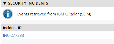
The security operator can click the hyperlink, which displays more detailed information about the issue. In the case depicted in Figure 3‑10, the HP Sure Start capability has flagged a potential issue.
Figure 3‑10 Incident Summary
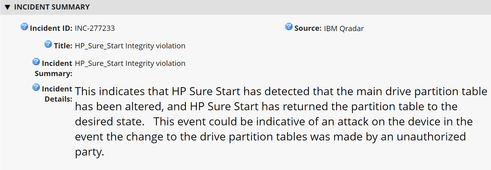
In the Incident Status section, metadata associated with the incident is displayed, including whether remediation is requested by the security operator. Figure 3‑11 shown an example of this.
Figure 3‑11 Incident Status
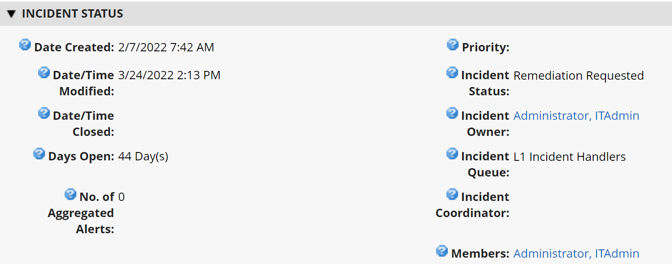
If remediation is requested, the security operator clicks the Remediation tab within the Security Incident where a suggested action is displayed (see Figure 3‑12).
Figure 3‑12 Incident Remediation Action