NIST SPECIAL PUBLICATION 1800-34B
Validating the Integrity of Computing Devices
Volume B:
Approach, Architecture, and Security Characteristics
Tyler Diamond*
Nakia Grayson
William T. Polk
Andrew Regenscheid
Murugiah Souppaya
National Institute of Standards and Technology
Information Technology Laboratory
Christopher Brown
The MITRE Corporation
McLean, Virginia
Karen Scarfone
Scarfone Cybersecurity
Clifton, Virgina
* Former employee; all work for this publication was done while at employer
December 2022
FINAL
This publication is available free of charge from https://doi.org/10.6028/NIST.SP.1800-34

DISCLAIMER
Certain commercial entities, equipment, products, or materials may be identified by name or company logo or other insignia in order to acknowledge their participation in this collaboration or to describe an experimental procedure or concept adequately. Such identification is not intended to imply special status or relationship with NIST or recommendation or endorsement by NIST or NCCoE; neither is it intended to imply that the entities, equipment, products, or materials are necessarily the best available for the purpose.
National Institute of Standards and Technology Special Publication 1800-34B, Natl. Inst. Stand. Technol. Spec. Publ. 1800-34B, 72 pages, (December 2022), CODEN: NSPUE2
FEEDBACK
As a private-public partnership, we are always seeking feedback on our practice guides. We are particularly interested in seeing how businesses apply NCCoE reference designs in the real world. If you have implemented the reference design, or have questions about applying it in your environment, please email us at supplychain-nccoe@nist.gov.
All comments are subject to release under the Freedom of Information Act.
NATIONAL CYBERSECURITY CENTER OF EXCELLENCE
The National Cybersecurity Center of Excellence (NCCoE), a part of the National Institute of Standards and Technology (NIST), is a collaborative hub where industry organizations, government agencies, and academic institutions work together to address businesses’ most pressing cybersecurity issues. This public-private partnership enables the creation of practical cybersecurity solutions for specific industries, as well as for broad, cross-sector technology challenges. Through consortia under Cooperative Research and Development Agreements (CRADAs), including technology partners—from Fortune 50 market leaders to smaller companies specializing in information technology security—the NCCoE applies standards and best practices to develop modular, adaptable example cybersecurity solutions using commercially available technology. The NCCoE documents these example solutions in the NIST Special Publication 1800 series, which maps capabilities to the NIST Cybersecurity Framework and details the steps needed for another entity to re-create the example solution. The NCCoE was established in 2012 by NIST in partnership with the State of Maryland and Montgomery County, Maryland.
NIST CYBERSECURITY PRACTICE GUIDES
NIST Cybersecurity Practice Guides (Special Publication 1800 series) target specific cybersecurity challenges in the public and private sectors. They are practical, user-friendly guides that facilitate the adoption of standards-based approaches to cybersecurity. They show members of the information security community how to implement example solutions that help them align with relevant standards and best practices, and provide users with the materials lists, configuration files, and other information they need to implement a similar approach.
The documents in this series describe example implementations of cybersecurity practices that businesses and other organizations may voluntarily adopt. These documents do not describe regulations or mandatory practices, nor do they carry statutory authority.
ABSTRACT
Organizations are increasingly at risk of cyber supply chain compromise, whether intentional or unintentional. Cyber supply chain risks include counterfeiting, unauthorized production, tampering, theft, and insertion of unexpected software and hardware. Managing these risks requires ensuring the integrity of the cyber supply chain and its products and services. This project demonstrates how organizations can verify that the internal components of the computing devices they acquire, whether laptops or servers, are genuine and have not been tampered with. This solution relies on device vendors storing information within each device, and organizations using a combination of commercial off-the-shelf and open-source tools that work together to validate the stored information. This NIST Cybersecurity Practice Guide describes the work performed to build and test the full solution.
KEYWORDS
computing devices; cyber supply chain; cyber supply chain risk management (C-SCRM); hardware root of trust; integrity; provenance; supply chain; tampering.
ACKNOWLEDGMENTS
We are grateful to the following individuals for their generous contributions of expertise and time. This document reflects each Individual’s affiliation as of the writing of this document, not subsequent changes.
Name |
Organization |
|---|---|
Themistocles Chronis |
Archer |
Dan Carayiannis |
Archer |
Jon Amis |
Dell Technologies |
Charles Robison |
Dell Technologies |
Mukund Khatri |
Dell Technologies |
Rick Martinez |
Dell Technologies |
Daniel Carroll |
Dell Technologies |
Jason Young |
Dell Technologies |
Travis Raines |
Eclypsium |
John Loucaides |
Eclypsium |
Jason Cohen |
Hewlett Packard Enterprise |
CJ Coppersmith |
Hewlett Packard Enterprise |
Ludovic Jacquin |
Hewlett Packard Enterprise |
Boris Balacheff |
HP Inc. |
Jeff Jeansonne |
HP Inc. |
Joshua Schiffman |
HP Inc. |
Harmeet Singh |
IBM |
Tom Dodson |
Intel |
Jason Ajmo |
The MITRE Corporation |
Chelsea Deane |
The MITRE Corporation |
Spike E. Dog |
The MITRE Corporation |
Joe Sain |
The MITRE Corporation |
Thomas Walters |
The MITRE Corporation |
Andrew Medak |
National Security Agency (NSA) |
Lawrence Reinert |
NSA |
Manuel Offenberg |
Seagate |
David Kaiser |
Seagate |
Paul Gatten |
Seagate |
Simon Phatigaraphong |
Seagate |
Bill Downer |
Seagate Government Solutions |
Jack Fabian |
Seagate Government Solutions |
The Technology Partners/Collaborators who participated in this build submitted their capabilities in response to a notice in the Federal Register. Respondents with relevant capabilities or product components were invited to sign a Cooperative Research and Development Agreement (CRADA) with NIST, allowing them to participate in a consortium to build this example solution. We worked with:
Technology Partner/Collaborator |
Build Involvement |
|---|---|
Archer Suite 6.9 |
|
PowerEdge R650, Secured Component Verification tool; Precision 3530, CSG Secured Component Verification tool |
|
Eclypsium Analytics Service, Eclypsium Device Scanner |
|
(2) Elitebook 840 G7, HP Sure Start, HP Sure Recover, Sure Admin, HP Client Management Script Library (CMSL), HP Tamperlock |
|
Proliant DL360 Gen 10, Platform Certificate Verification Tool (PCVT) |
|
QRadar SIEM |
|
HP Inc. Elitebook 360 830 G5, Lenovo ThinkPad T480, Transparent Supply Chain Tools, Key Generation Facility, Cloud Based Storage, TSCVerify and AutoVerify software tools |
|
Host Integrity at Runtime and Start-Up (HIRS), Subject Matter Expertise |
|
(3) 18TB Exos X18 hard drives, 2U12 Enclosure, Firmware Attestation API, Secure Device Authentication API |
DOCUMENT CONVENTIONS
The terms “shall” and “shall not” indicate requirements to be followed strictly to conform to the publication and from which no deviation is permitted. The terms “should” and “should not” indicate that among several possibilities, one is recommended as particularly suitable without mentioning or excluding others, or that a certain course of action is preferred but not necessarily required, or that (in the negative form) a certain possibility or course of action is discouraged but not prohibited. The terms “may” and “need not” indicate a course of action permissible within the limits of the publication. The terms “can” and “cannot” indicate a possibility and capability, whether material, physical, or causal.
PATENT DISCLOSURE NOTICE
NOTICE: The Information Technology Laboratory (ITL) has requested that holders of patent claims whose use may be required for compliance with the guidance or requirements of this publication disclose such patent claims to ITL. However, holders of patents are not obligated to respond to ITL calls for patents and ITL has not undertaken a patent search in order to identify which, if any, patents may apply to this publication.
As of the date of publication and following call(s) for the identification of patent claims whose use may be required for compliance with the guidance or requirements of this publication, no such patent claims have been identified to ITL.
No representation is made or implied by ITL that licenses are not required to avoid patent infringement in the use of this publication.
List of Figures
Figure 4‑1 Notional Architecture
Figure 4‑2 Component-Level Architecture
Figure 4‑4 Network Boot Services Environment
Figure 4‑5 Platform Manifest Correlation System
Figure 4‑6 Eclypsium Management Console
Figure 4‑7 Eclypsium Analytic Platform Server Implementation
Figure 4‑8 Eclypsium Analytic Platform Laptop Implementation
Figure 4‑9 Seagate Secure Drive Authentication Integration
Figure 4‑10 Seagate Firmware Attestation Integration
Figure 5‑1 Platform Certificate Binding to Endorsement Credential
Figure 5‑2 Intel Transparent Supply Chain Download Portal
Figure 5‑3 HIRS ACA Validation Dashboard
Figure 5‑4 Asset Inventory and Discovery Example 1
Figure 5‑5 Asset Inventory and Discovery Example 2
Figure 5‑6 Asset Inventory and Discovery Example 3
Figure 5‑7 Scenario 3 Dashboard
Figure 5‑8 Scenario 3 Security Event
Figure 5‑9 Scenario 3 Security Event Summary
Figure 5‑10 Scenario 3 Security Event Remediation
Figure C‑1 Dell and HP Inc. Laptop Scenario 2 Part 1
Figure C‑2 Dell and HP Inc. Laptop Scenario 2 Part 2
Figure C‑3 Intel Laptop Scenario 2 Part 1
Figure C‑4 Intel Laptop Scenario 2 Part 2
Figure C‑5 Intel Server Scenario 2 Part 1
Figure C‑6 Intel Server Scenario 2 Part 2
Figure C‑7 Dell Server Scenario 2
Figure C‑8 HPE Server Scenario 2
Figure C‑9 Intel Laptop Scenario 3
Figure C‑10 Dell Laptops Scenario 3
Figure C‑11 HP Inc. Laptops Scenario 3
List of Tables
Table 3‑1 NIST SP 800-161 Revision 1 Threat Events
Table 3‑2 C-SCRM Example Threat Scenario
Table 3‑3 Security Characteristics
Table 3‑4 Security Characteristics and Controls Mapping
Table 3‑5 Products and Technologies
Table 5‑1 Demonstration Verifiable Artifact
Table 5‑2 Seagate Drive Verifiable Artifacts
1 Summary
The supply chains of information and communications technologies are increasingly at risk of compromise. Additional risks causing supply chain disruptions include counterfeiting, unauthorized production, tampering, theft, and insertion of unexpected software and hardware. Managing these risks requires ensuring the integrity of the cyber supply chain and its products and services. This prototype implementation demonstrates how organizations can verify that the internal components of the computing devices they acquire are genuine and have not been unexpectedly altered during manufacturing or distribution processes.
This guide includes proof-of-concept software tools and services which have not been commercialized as of this writing. We encourage adopters to experiment with the guidelines in a test or development environment, with the understanding that they will encounter gaps and challenges.
This project was conducted in two phases: laptop and server builds. The first phase focused on validating the integrity of laptop hardware contributed by our technology partners. In the second phase, we incorporated hardware from our server and component manufacturing partners. The server build leveraged and extended much of the laptop build architecture. The second phase also added a Security Information and Event Management (SIEM) component to the architecture that enhanced our ability to monitor and detect unauthorized component swaps and firmware changes. We hope that this approach will provide organizations with a holistic methodology for managing supply chain risk.
For ease of use, the following provides a short description of each section in this volume.
Section 1, Summary, presents the challenge addressed by this National Cybersecurity Center of Excellence (NCCoE) project, including our approach to addressing the challenge, the solution demonstrated, and the benefits of the solution.
Section 2, How to Use This Guide, explains how business decision makers, program managers, and information technology (IT) and operational technology (OT) professionals might use each volume of the guide.
Section 3, Approach, offers a detailed treatment of the scope of the project, the risk assessment that informed the solution, and the technologies and components that industry collaborators supplied to build the example solution.
Section 4, Architecture, specifies the components of the prototype implementation and details how data and communications flow between validation systems.
Section 5, Security Characteristic Analysis, provides details about the tools and techniques used to test and understand the extent to which the project prototype implementation meets its objective: demonstrating how organizations can verify that the components of their acquired computing devices are genuine and have not been tampered with or otherwise modified throughout the devices’ life cycles.
Section 6, Future Build Considerations, conveys the technical characteristics we plan to incorporate as we continue to prototype with our collaborators.
Appendices A through C provide acronyms, a list of references cited in this volume, and project scenario sequence diagrams, respectively.
1.1 Challenge
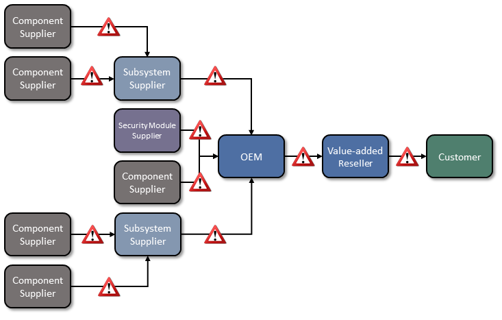
Technologies today rely on complex, globally distributed, and interconnected supply chain ecosystems to provide highly refined, cost-effective, versatile, and reusable solutions. Most organizations’ security processes consider only the visible state of computing devices. The provenance and integrity of a delivered device and its components are typically accepted without validating through technology that there have been no unexpected modifications. Provenance is the comprehensive history of a device throughout the entire life cycle from creation to ownership, including changes made within the device or its components. Assuming that all acquired computing devices are genuine and unmodified increases the risk that a compromise will affect products in an organization’s supply chain, which in turn increases risks to customers and end users, as illustrated in Figure 1‑1. Mitigating this risk is not addressed at all in many cases.
Figure 1‑1 Supply Chain Risk
Organizations currently lack the ability to readily distinguish trustworthy products from others. At best, government organizations could access an information source on counterfeit components such as the Government-Industry Data Exchange Program (GIDEP), which contains information on equipment, parts, and assemblies that are suspected to be counterfeit. Additionally, organizations with sufficient resources could have acquisition quality assurance programs that examine manufacturer supply chain practices, perform spot-checks of deliveries, and/or require certificates of conformity.
Having the ability to distinguish trustworthy and untrustworthy products is a critical foundation of cyber supply chain risk management (C-SCRM). C-SCRM is the process of identifying, assessing, and mitigating the risks associated with the distributed and interconnected nature of supply chains. C-SCRM presents challenges to many industries and sectors, requiring a coordinated set of technical and procedural controls to mitigate cyber supply chain risks throughout manufacturing, acquisition, provisioning, and operations.
1.2 Solution
To address these challenges, the NCCoE has collaborated with technology vendors to develop a prototype implementation. This project [B1] demonstrates how organizations can verify that the internal components of the computing devices they acquire are genuine and have not been tampered with. This solution relies on device vendors storing information within each device, and implementers using a combination of commercial off-the-shelf and open-source tools that work together to validate the stored information. By doing this, organizations can reduce the risk of compromise to products within their supply chains.
In this approach, device vendors create one or more artifacts within each device that securely bind the device’s attributes to the device’s identity. An organization that acquires the device can validate the artifacts’ source and authenticity, then check the attributes stored in the artifacts against the device’s actual attributes to ensure they match before fielding the device to the end user. A similar process can be used to periodically verify the integrity of computing devices while they are in use.
Attributes are bound to hardware roots of trust. A hardware root of trust is a set of highly reliable firmware and software components upon which the computing system’s trust model is built. They form a foundation in hardware for providing one or more critical security functions for the system. By leveraging hardware roots of trust while a computing device traverses the supply chain, we can maintain trust in the computing device throughout its operational lifecycle.
Platform firmware and its associated configuration data is critical to the trustworthiness of a computing system [B2]. Because of the highly privileged position platform firmware has with hardware, in this prototype we also leverage a system firmware integrity detection component that includes mechanisms for detecting when platform firmware code and critical data have been corrupted. These mechanisms complement the hardware authenticity process described above.
This project addresses several processes, including:
how to create verifiable descriptions of components and platforms, which may be done by original equipment manufacturers (OEMs), platform integrators, and even IT departments;
how to verify the integrity and provenance of computing devices and components within the single transaction between an OEM and a customer; and
how to continuously monitor the integrity of computing devices and components at subsequent stages in the system lifecycle in the operational environment.
1.3 Benefits
This practice guide can help organizations, including but not limited to OEMs and third-party component suppliers, to:
avoid using compromised technology components in your products
enable customers to readily verify that OEM products are genuine and trustworthy
prevent compromises of your organization’s information and systems caused by acquiring and using compromised technology products
avoid future compromises to the organization by continuously monitoring computing devices for platform integrity issues
implement zero trust architecture solutions and take advantage of the results of this project to help inform their policy to determine if access is authorized
2 How to Use This Guide
This NIST Cybersecurity Practice Guide demonstrates a standards-based reference design for verifying that the internal components of the computing devices organizations acquire are genuine and have not been tampered with, and provides readers with the information they need to replicate the reference design. This reference design is modular and can be deployed in whole or in part.
This guide contains three volumes:
NIST Special Publication (SP) 1800-34A: Executive Summary
NIST SP 1800-34B: Approach, Architecture, and Security Characteristics—what we built and why (you are here)
NIST SP 1800-34C: How-To Guides—instructions for building the example solution
Depending on your role in your organization, you might use this guide in different ways:
Business decision makers, including chief security and technology officers, will be interested in the Executive Summary, NIST SP 1800-34A, which describes the following topics:
challenges that enterprises face in decreasing the risk of a compromise to products in their supply chain
example solution built at the NCCoE
benefits of adopting the example solution
Technology or security program managers who are concerned with how to identify, understand, assess, and mitigate risk will be interested in this part of the guide, NIST SP 1800-34B, which describes what we did and why. The following sections will be of particular interest:
Section 3.4, Risk Assessment, provides a description of the risk analysis we performed
Section 3.5, Security Control Map, maps the security characteristics of this example solution to cybersecurity standards and best practices
You might share the Executive Summary, NIST SP 1800-34A, with your leadership team members to help them understand the importance of adopting a standards-based method for verifying that the internal components of the computing devices they acquire are genuine and have not been tampered with.
IT professionals who want to implement an approach like this will find the whole practice guide useful. You can use the how-to portion of the guide, NIST SP 1800-34C, to replicate all or parts of the build created in our lab. The how-to portion of the guide provides specific product installation, configuration, and integration instructions for implementing the example solution. We do not re-create the product manufacturers’ documentation, which is generally widely available. Rather, we show how we incorporated the products together in our environment to create an example solution.
This guide assumes that IT professionals have experience implementing security products within the enterprise. While we have used a suite of commercial and open-source products to address this challenge, this guide does not endorse these particular products. Your organization can adopt this solution or one that adheres to these guidelines in whole, or you can use this guide as a starting point for tailoring and implementing parts of a prototype implementation for verifying that the internal components of the computing devices your organization acquires are genuine and have not been tampered with. Your organization’s security experts should identify the products that will best integrate with your existing tools and IT system infrastructure. We hope that you will seek products that are congruent with applicable standards and best practices. Section 3.6, Technologies, lists the products we used and maps them to the cybersecurity controls provided by this reference solution.
A NIST Cybersecurity Practice Guide does not describe “the” solution, but a possible solution. Comments, suggestions, and success stories will improve subsequent versions of this guide. Please contribute your thoughts to supplychain-nccoe@nist.gov.
2.1 Typographic Conventions
The following table presents typographic conventions used in this volume.
Typeface/ Symbol |
Meaning |
Example |
|---|---|---|
Italics |
file names and path names; references to documents that are not hyperlinks; new terms; and placeholders |
For language use and style guidance, see the NCCoE Style Guide. |
Bold |
names of menus, options, command buttons, and fields |
Choose File > Edit. |
|
command-line input, onscreen computer output, sample code examples, and status codes |
|
Monospace (block)
|
multi-line input, on-screen computer output, sample code examples, status codes |
% mkdir -v nccoe_projects
mkdir: created directory 'nccoe_projects'
|
link to other parts of the document, a web URL, or an email address |
All publications from NIST’s NCCoE are available at https://www.nccoe.nist.gov. |
3 Approach
To help organizations cost-effectively distinguish trustworthy products from others, this guide describes an adaptable prototype implementation that organizations can use to verify that the internal components of the computing devices they acquire are genuine and have not been tampered with. The NCCoE leveraged the existing ongoing work from the NIST C-SCRM program, including workshop proceedings, research findings, and use case studies, and gathered expert opinion from technology and cybersecurity vendors, academia, and government to define the project scope and reference architecture.
3.1 Audience
This guide is intended for organizations and individuals who are responsible for the acquisition, provisioning, and configuration control of computing devices. Examples include IT administrators/system administrators, incident response team members, and Security Operations Center (SOC) staff. OEMs, value-added resellers (VARs), and component suppliers may also benefit from the prototype and lessons-learned at the conclusion of this project.
3.2 Scope
The scope of the project is limited to technical activities that can be undertaken by OEMs and their approved manufacturers to prevent and detect counterfeits, tampering, and undocumented changes to firmware and hardware, and the corresponding customer processes to verify that client and server computing devices and components have not been tampered with or otherwise modified. Protection against undocumented changes to the operating system (OS) is considered out of scope for this project. Activities or security protections that cannot be electronically verified by the customer are also explicitly out of scope.
Further, this project is not intended to cover the entire supply chain risk management process; it focuses on the acceptance testing portion of a more holistic defense-in-depth/defense-in breadth supply chain risk management strategy. The project enables verification of the identity of computing devices (including replacement parts and updates or upgrades) once they have been acquired but before they are implemented or installed.
Finally, this volume documents our experiences with laptop (client) computing devices in a Windows 10 environment and servers that use Linux operationally in the prototype. From this perspective, we have defined the following three project scenarios which outline the prototype scope.
3.2.1 Scenario 1: Creation of Verifiable Platform Artifacts
An OEM, VAR, or other authoritative source creates a verifiable artifact that binds reference platform attributes to unique, trusted, hardware-based components of the computing device. The platform attributes in this artifact (e.g., serial number, embedded components, firmware and software information, platform configuration) are used by the purchasing organization during acceptance and provisioning of the computing device. Customers may also create their own platform artifacts to establish a baseline that could be used to validate devices in the field.
3.2.2 Scenario 2: Verification of Components During Acceptance Testing
In this scenario, an IT administrator receives a computing device through non-verifiable channels (e.g., off the shelf at a retailer) and wishes to confirm its provenance and authenticity as part of acceptance testing and to establish an authoritative asset inventory as part of an asset management program.
3.2.3 Scenario 3: Verification of Components During Use
In this scenario, the computing device has been accepted by the organization (Scenario 2) and has been provisioned for the end user. The computing device components are verified against the attributes and measurements declared by the manufacturer or purchasing organization during operational usage.
3.3 Assumptions
This project is guided by the following assumptions:
The scenario activities above will augment, not replace, the capabilities of existing acceptance testing tools, asset management systems, and configuration management systems.
Hardware roots of trust represent one technique that can be used to bind attributes to a product. However, OEMs may use different approaches to implement equivalent capabilities.
Organizational computing devices lifecycle phases for technology include (among others) the following activities described in NIST SP 800-161 Revision 1, Cybersecurity Supply Chain Risk Management Practices for Systems and Organizations [B3]: integration (including acceptance testing as described in this demonstration), operations, and disposal.
3.4 Risk Assessment
NIST SP 800-30 Revision 1, Guide for Conducting Risk Assessments [B4], states that risk is “a measure of the extent to which an entity is threatened by a potential circumstance or event, and typically a function of: (i) the adverse impacts that would arise if the circumstance or event occurs; and (ii) the likelihood of occurrence.” The guide further defines risk assessment as “the process of identifying, estimating, and prioritizing risks to organizational operations (including mission, functions, image, reputation), organizational assets, individuals, other organizations, and the Nation, resulting from the operation of an information system. Part of risk management incorporates threat and vulnerability analyses, and considers mitigations provided by security controls planned or in place.”
The NCCoE recommends that any discussion of supply chain risk management should begin with a comprehensive review of NIST SP 800-161 Revision 1, Cybersecurity Supply Chain Risk Management Practices for Systems and Organizations [B3] (publicly available). While NIST SP 800-161 is targeted to U.S. federal agencies, much of the guidance is beneficial to private organizations interested in reducing Information and Communications Technology (ICT) supply chain risk. An ICT supply chain compromise can occur anywhere within the system development life cycle of the product or service.
In addition, NIST SP 800-37 Revision 2, Risk Management Framework for Information Systems and Organizations [B5] provides Risk Management Framework guidance that gives a baseline for assessing risks to information system assets, including threats to the IT system supply chain.
3.4.1 Threats
NIST SP 800-161 Revision 1 provides a framework of ICT supply chain threats including insertion of counterfeits, unauthorized production, tampering, theft, and insertion of malicious software and hardware, as well as poor manufacturing and development practices in the ICT supply chain. These threats are associated with an organization’s decreased visibility into, and understanding of, how the technology that it acquires is developed, integrated, and deployed, as well as the processes, procedures, and practices used to assure the integrity, security, resilience, and quality of the products and services. Exploits created by malicious actors (individuals, organizations, or nation states) are often especially sophisticated, difficult to detect, and have the potential to result in significant and lasting impact. This prototype implementation does not defend against all ICT threats, but Table 3‑1 captures threats from NIST SP 800-161 Revision 1 that are relevant to this project.
Table 3‑1 NIST SP 800-161 Revision 1 Threat Events
Threat Events |
Description |
|---|---|
Craft attacks specifically based on deployed IT environment. |
Adversary develops attacks (e.g., crafts targeted malware) that take advantage of knowledge of the organizational IT environment. |
Create counterfeit/spoof website. |
Adversary creates duplicates of legitimate websites; when users visit a counterfeit site, the site can gather information or download malware. |
Craft counterfeit certificates. |
Adversary counterfeits or compromises a certificate authority (CA) so that malware or connections will appear legitimate. |
Create and operate false front organizations to inject malicious components into the supply chain. |
Adversary creates false front organizations with the appearance of legitimate suppliers in the critical life cycle path that then inject corrupted/malicious information system components into the organizational supply chain. |
Insert counterfeit or tampered hardware into the supply chain. |
Adversary intercepts hardware from legitimate suppliers. Adversary modifies the hardware or replaces it with faulty or otherwise modified hardware. |
Insert tampered critical components into organizational systems. |
Adversary replaces, through supply chain, subverted insider, or some combination thereof, critical information system components with modified or corrupted components. |
Compromise design, manufacture, and/or distribution of information system components (including hardware, software, and firmware). |
Adversary compromises the design, manufacture, and/or distribution of critical information system components at selected suppliers. |
Conduct supply chain attacks targeting and exploiting critical hardware, software, or firmware. |
Adversary targets and compromises the operation of software (e.g., through malware injections), firmware, or hardware that performs critical functions for organizations. This is largely accomplished as supply chain attacks on both commercial off-the-shelf and custom information systems and components. |
Obtain unauthorized access. |
Adversary with authorized access to organizational information systems gains access to resources that exceeds authorization. |
Inadvertently introduce vulnerabilities into software products. |
Due to inherent weaknesses in programming languages and software development environments, errors and vulnerabilities are introduced into commonly used software products. |
3.4.2 Vulnerabilities
This document is guided by NIST SP 800-161 Revision 1 [B3], which describes an ICT supply chain vulnerability as the following:
“A vulnerability is a weakness in an information system, system security procedures, internal controls, or implementation that could be exploited or triggered by a threat source […]. Within the ICT SCRM context, it is any weakness in the system/component design, development, manufacturing, production, shipping and receiving, delivery, operation, and component end-of life that can be exploited by a threat agent. This definition applies to both the systems/components being developed and integrated (i.e., within the SDLC) and to the ICT supply chain infrastructure, including any security mitigations and techniques, such as identity management or access control systems. ICT supply chain vulnerabilities may be found in:
The systems/components within the SDLC (i.e., being developed and integrated);
The development and operational environment directly impacting the SDLC; and
The logistics/delivery environment that transports ICT systems and components (logically or physically).”
In the context of this project, ICT products (including libraries, frameworks, and toolkits) or services originating anywhere (domestically or abroad) might contain vulnerabilities that can present opportunities for ICT supply chain compromises. For example, an adversary may have the power to insert a malicious component into a product. While it is important to consider all ICT vulnerabilities, in practice it is impossible to completely eliminate all of them. Therefore, organizations should prioritize vulnerabilities that may have a greater potential to severely impact their environment if exploited by an adversary.
Additionally, a goal of this prototype implementation is to document a capability that enables organizations to detect the exploitation of vulnerabilities that may exist in firmware over-the-air processes that would allow an attacker to gain a privileged position on the computing device. In this project, we introduce a continuous monitoring component within system firmware that organizations can incorporate into their continuous monitoring programs.
3.4.3 Risk
SP 800-161 Revision 1 [B3] provides an analysis framework for organizations to assess supply chain risk by creating a threat scenario—a summary of potential consequences of the successful exploitation of a specific vulnerability or vulnerabilities by a threat agent. By performing this exercise, organizations can identify areas requiring increased controls. Here, we walk through a truncated example scenario that may be similar to a threat scenario faced by organizations who implement some or all parts of this prototype demonstration. Readers are encouraged to develop their own threat scenario assessment for their organization as part of a larger risk management program.
3.4.3.1 Threat Scenario
A company purchases replacement server computing devices from a third-party VAR with whom it has done business in the past. The business side of the company is pressuring the IT Operations staff to rapidly replace the servers during off-hours to avoid downtime during regular business hours. The IT department responds by accelerating its deployment schedule to nights and weekends, using existing staff augmented with VAR technicians.
Following deployment of the new hardware, the IT department observes that computing performance is slower in the subnets where the equipment has been installed. Two weeks of load tests are conducted to validate the performance issues, culminating with a report that the new hardware is 25% slower than the previous hardware.
At the same time, the company’s Information Security department notices traffic they don’t recognize coming from the new servers in the upgraded subnets. Their investigation finds that these servers in the affected subnets are beaconing out to international IP addresses where the company has no business presence or need. The servers generating the suspicious traffic are taken offline for further investigation.
The VAR is called, and their technicians perform a separate analysis, confirming the reduction in computing performance. The VAR launches an investigation into the source of the servers that they sold to the company and finds some of the components in the equipment in question, as well as a portion of their warehouse stock of components, are counterfeit. The VAR sends a representative server to a security company for analysis. The security company finds that in addition to counterfeit and substandard components, embedded malware has been installed, enabling attackers to take control of the servers and to deliver second-stage malware that enabled them to move laterally through the affected subnets and compromise computers of interest. This also gave the attackers a persistent foothold inside the company.
An internal audit finds multiple failures on the part of the purchasing department, the IT department, and the Information Security group to have in place measures to ensure the provenance of the equipment and the secure deployment of devices on the network.
As a result of the supply chain breach leading to the installation of compromised hardware, the company suffered several adverse effects, including:
loss of intellectual property through data exfiltration
loss of employee productivity as computers and network equipment were taken offline
additional costs to investigate and replace computers and network equipment
loss of confidence with the company’s client base
potential loss of revenue due to clients severing their relationship with the company
Consequently, the organization develops three mitigation strategies to address the identified risks, in which two are chosen as shown in Table 3‑2. One of the chosen strategies, Increase provenance and information requirements, can be at least partially addressed by the final implementation of this project. Table 3‑2 presents a summary of an example threat scenario analysis framework that an organization may use to determine the controls to implement that would cause the estimated residual risk of counterfeit hardware to drop to an acceptable level.
Table 3‑2 C-SCRM Example Threat Scenario
Threat Scenario |
Threat Source: |
Industrial espionage/cyber criminals |
Vulnerability: |
Internal: Loss of intellectual property following system compromise |
|
Threat Event Description: Existing Practices: |
Counterfeit hardware with embedded malware introduced into company’s network Hardware system test prior to deployment; network scanning |
|
Outcome: |
Data exfiltration, system degradation, loss of productivity, loss of revenue |
|
Risk |
Impact: |
30% chance of successful targeting and infiltration |
Likelihood: |
40% chance of undetected compromise |
|
Risk Score (Impact x Likelihood): |
High |
|
Acceptable Level of Risk: |
Low (under 25%) |
|
Mitigation |
Potential Mitigating Strategies/ SCRM Controls: |
|
Estimated Cost of Mitigating Strategies: |
|
|
New Risk Score: |
Low |
|
Selected Strategies: |
|
|
Estimated Residual Risk: |
10% |
3.5 Security Control Map
The following tables map the security characteristics defined in our project description (Table 3‑3) to the applicable NIST Cybersecurity Framework [B6] Functions, Categories, and Subcategories (Table 3‑4) to assist organizations better manage and reduce C-SCRM risk. We have also included a mapping to specific SP 800-53 r5 security controls [B7] and indicated (in bold) if the control is part of the SP 800-161 Revision 1 [B3] baseline security controls to assist organizations interested in alignment with NIST C-SCRM best practices.
Table 3‑3 Security Characteristics
Identifier |
Security Characteristic |
|---|---|
1 |
Establish a unique device identity to support binding artifacts to a specific device. |
2 |
Cryptographically bind platform attributes and other manufacturing information to a given computer system. |
3 |
Maintain assurance for multi-supplier production in which components are embedded at various stages. |
4 |
Perform acceptance testing to validate source and integrity of assembled components for the recipient organization of the computer system. |
5 |
Detect unexpected component (firmware) swaps or tampering during the life cycle of the computing device in an operational environment. |
Table 3‑4 Security Characteristics and Controls Mapping
Cybersecurity Framework v1.1 |
SP 800-53 R5 |
Security Characteristics Addressed |
||
|---|---|---|---|---|
Function |
Category |
Subcategory |
||
Identify (ID) |
Supply Chain Risk Management (ID.SC) |
ID.SC-4: Suppliers and third-party partners are routinely assessed using audits, test results, or other forms of evaluations to confirm they are meeting their contractual obligations. |
AU-6 |
5 |
Asset Management (ID.AM) |
ID.AM-1: Physical devices and systems within the organization are inventoried. |
CM-8 |
4 |
|
Protect (PR) |
Identity Management, Authentication and Access Control (PR.AC) |
PR.AC-6: Identities are proofed and bound to credentials and asserted in interactions. |
IA-4 |
1 |
Data Security (PR.DS) |
PR.DS-6: Integrity checking mechanisms are used to verify software, firmware, and information integrity. |
SI-7 |
4, 5 |
|
PR.DS-8: Integrity checking mechanisms are used to verify hardware integrity. |
SA-10 |
4, 5 |
||
Protective Technology (PR.PT) |
PR.PT-1: Audit/log records are determined, documented, implemented, and reviewed in accordance with policy. |
AU-2 |
5 |
|
Detect (DE) |
Security Continuous Monitoring (DE.CM) |
DE.CM-7: Monitoring for unauthorized personnel, connections, devices, and software is performed. |
PE-20 |
5 |
Detection Processes (DE.DP) |
DE.DP-2: Detection activities comply with all applicable requirements. |
SR-9 |
1 |
|
NA |
NA |
NA |
SR-10 |
5 |
NA |
NA |
NA |
SR-11 |
1,3 |
NA |
NA |
NA |
AU-10 |
4 |
3.6 Technologies
Table 3‑5 lists all of the technologies used in this project and provides a mapping among the generic component term, the specific product or technology used, the function or capability it provides, and the Cybersecurity Framework Subcategories that the product helps support. Refer to Table 3‑4 for an explanation of the NIST Cybersecurity Framework Subcategory codes. While Archer is presented as an Integrated Risk Management (IRM) platform in Table 3‑5, we are only leveraging a subset of capabilities of the platform in the project to manage risk by providing visibility, reporting, and alerting for the managed assets at the firmware level.
Table 3‑5 Products and Technologies
Component |
Product/Technology |
Function/Capability |
Cybersecurity Framework Subcategories |
|---|---|---|---|
Component or Subsystem Manufacturer |
Intel Transparent Supply Chain |
Tools and processes to ensure supply chain security from the manufacturer to the purchasing organization |
ID.SC-4, |
Seagate EXOS X18 18 Terabyte Hard Drive |
Secure device authentication, firmware attestation |
ID.SC-4, |
|
OEM or VAR |
Dell Technologies |
Manufactures computing devices and binds them to verifiable artifacts |
ID.SC-4 |
Hewlett Packard Enterprise |
|||
HP Inc. |
|||
Intel |
|||
Computing Device |
Dell PowerEdge R650 Server |
A client device (laptop) or server purchased by an organization to execute tasks by end users |
ID.SC-4, |
Dell Latitude 5420/5520 |
|||
HPE ProLiant DL360 |
|||
HP Inc. Elitebook 360 830 G5 |
|||
HP Inc. 840 G7/Zbook Firefly 14 G7 |
|||
Intel Server Board S2600WTT |
|||
Lenovo ThinkPad T480 |
|||
Integrated Risk Management Platform |
Archer IRM Platform |
Ensures computing devices and associated components are tracked, uniquely identified, and managed through integrations with Asset Discovery tools. Provides visibility and workflows for addressing security incidents imported from SIEM tools |
ID.AM-1, |
Configuration Management System |
Microsoft Configuration Manager |
Enforces corporate governance and policies through actions such as applying software patches and updates, removing denylisted software, and automatically updating configurations |
DE.CM-7 |
Security Information and Event Management Tool |
IBM QRadar |
Performs real-time analysis of alerts and notifications generated by organizational information systems |
DE.CM-7 |
Certificate Authority (CA) |
Host Integrity at Runtime and Start-up (HIRS) Attestation Certificate Authority (ACA) |
Issues an Attestation Identity Credential in accordance with Trusted Computing Group (TCG) specifications |
PR.AC-6, |
Platform Integrity Validation System |
Eclypsium Analytic Platform |
Validates the integrity of firmware installed on computing devices |
PR.DS-6 |
HIRS ACA |
Validates platform components in accordance with TCG specifications |
PR.DS-8 |
|
Platform Certificate Verification Tool (PCVT) |
Validates platform components in accordance with TCG specifications |
PR.DS-8 |
|
Secure Component Verification (SCV) |
Validates platform components in accordance with TCG specifications |
PR.DS-8 |
|
Platform Manifest Correlation System |
Ingests platform manifest data from participating manufacturers |
ID.AM-1 |
3.6.1 Trusted Computing Group
The technology providers for this prototype implement standards from the TCG, a not-for-profit organization formed to develop, define, and promote open, vendor-neutral, global industry standards supportive of hardware-based roots of trust for interoperable trusted computing platforms. TCG developed and maintains the Trusted Platform Module (TPM) 2.0 specification [B8], which defines a cryptographic microprocessor designed to secure hardware by integrating cryptographic keys and services. A TPM functions as a root of trust for storage, measurement, and reporting. TPMs are currently included in many computing devices.
This project applies this foundational technology to address the challenge of operational security by verifying the provenance of a delivered system from the time it leaves the manufacturer until it is introduced in the organization’s operational environment. The TPM can be leveraged to measure and validate the state of the system, including:
binding attributes about the computing device to a strong cryptographic device identity held by the TPM, and
supporting measurement and attestation capabilities that allow an organization to inspect and verify device components and compare them to those found in the platform attribute credential and OEM-provided reference measurements.
4 Architecture
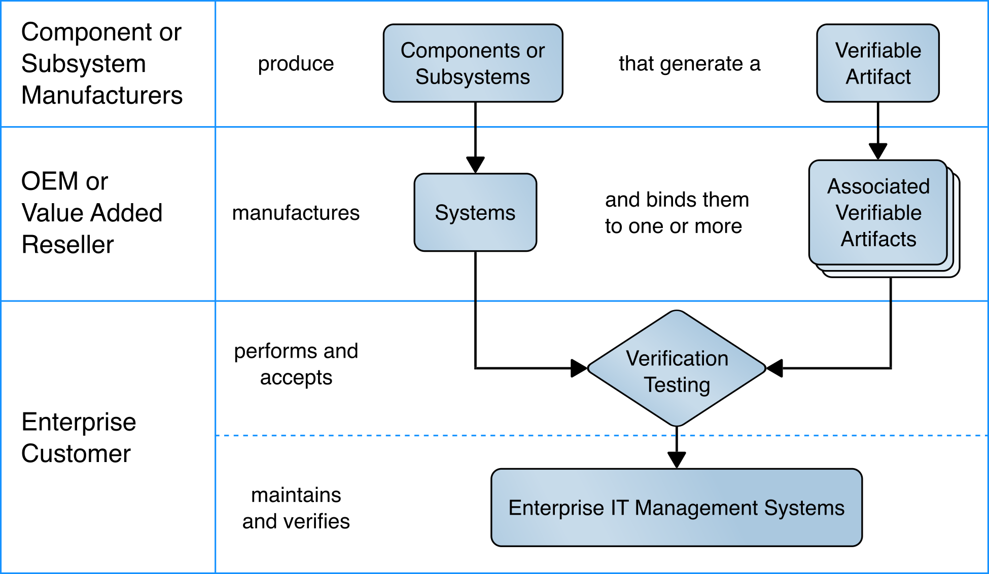
This project is based on the notional high-level architecture depicted in Figure 4‑1 for an organization incorporating C-SCRM technologies into its existing infrastructure. The architecture depicts a manufacturer that creates a hardware-root-of-trust-backed verifiable artifact associated with a computing device. The verifiable artifact is then associated with existing enterprise IT management systems, such as asset and configuration management systems, during the provisioning process. Finally, an inspection component measures and reports on hardware attributes and firmware measurements during acceptance testing and operational use.
Figure 4‑1 Notional Architecture
4.1 Architecture Description
The prototype architecture consists of two focus areas: 1) an implementation of a manufacturer that creates a hardware-root-of-trust-backed verifiable artifact associated with a computing device, and 2) the representational architecture of an organization where end users are issued computing devices that require access to enterprise services for initial acceptance testing of the device and operational validation of the platform.
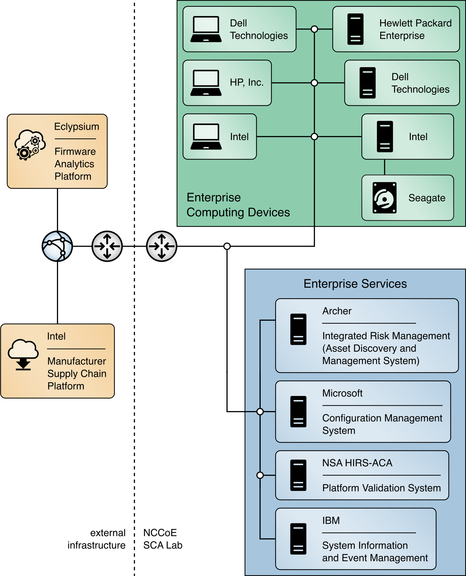
This prototype implementation combines on-premises software and infrastructure, cloud platforms, and end-user hardware to demonstrate the security characteristics defined in the project description (Table 3‑3). Figure 4‑2 presents a component-level view of the prototype. The remaining sections discuss the existing IT components an organization may have deployed before the prototype has been implemented and how they can be augmented to support a hardware integrity validation capability. They also discuss additional services and platforms that are integrated into the enterprise architecture.
Figure 4‑2 Component-Level Architecture
4.2 Existing Enterprise IT Management Systems
This prototype solution aims to augment, not replace, the capabilities of existing acceptance testing tools, asset management systems, configuration management systems, and SIEM systems. The following sections describe each existing capability a typical enterprise may have in operation before deciding to adopt the security characteristics defined in Section 3.5. Each section also describes the specific product that we used to demonstrate each security characteristic.
4.2.1 SIEM Tools
SIEM tools monitor and provide real-time analysis of alerts and notifications generated by organizational information systems. They support the Cybersecurity Framework’s Detect function to enable the timely discovery of cybersecurity events. A typical use case of SIEM is to consolidate security-related information from organizational client endpoints, where they can be correlated to identify significant events. This demonstration extends this use case to include platform integrity security events collected during operational use from agents installed on laptops.
SIEM tools commonly have a dashboard capability as well, which organizations use to present security event data in a human-friendly, unified view, sometimes referred to as “single pane of glass.” In this demonstration, we use dashboards to gain better visibility into potential supply chain attacks.
4.2.1.1 IBM QRadar
We demonstrate the capabilities described above with IBM QRadar—a SIEM platform which supports the collection of security events and automated processing of events by way of rules that align with an organization’s risk posture. We leverage two of its core capabilities, the log manager and the SIEM. The log manager is the component that collects, analyzes, stores, and reports on security event logs from Dell and HP Inc. laptop endpoints. The SIEM consolidates data gathered by the log manager and executes our custom ruleset which detects potential platform integrity events. This results in identifying offenses, events that security operations personnel may need to take remediation action on, which can be consumed by other enterprise systems (such as Dashboards) via the QRadar Representational State Transfer (REST) application programming interface (API).
4.2.2 Asset Discovery and Management System
SP 800-128 [B9] states that a system component is a discrete identifiable IT asset that represents a building block of a system. An accurate component inventory is essential to record the components that compose the system. The component inventory helps to improve the security of the system by providing a comprehensive view of the components that need to be managed and secured. The organization can determine the granularity of the components, and in the context of this prototype, the system is the computing device platform, and the components represent the internal hardware such as motherboard, hard drive, and memory.
For enabling such an inventory capability, in our project description [B1] we described an Asset Discovery and Management System as part of an enterprise architecture which helps organizations ensure that critical assets (systems) are uniquely identified using known identifiers and device attributes. This capability could include discovery tools that identify endpoints and interrogate the platform for device attributes. However, this prototype demonstration uses alternative platforms for these functions that are described in Section 4.2.4.
4.2.2.1 Archer Integrated Risk Management (IRM) Platform
To demonstrate this capability, we used the Archer IRM Platform which supports organizational management of governance, risk, and compliance programs. The IRM Platform serves as the foundation for the Archer asset management and Cyber Incident and Breach Response solutions and allows an organization to adapt it to C-SCRM requirements and integrate it with other external data sources. This prototype demonstration incorporates and extends Archer use cases centered on asset management and security operations.
Archer is a web-based platform that can be deployed on-premises or via a Software as a Service (SaaS) model that operates on a Microsoft stack consisting of Windows Server, Internet Information Services, and SQL Server. This prototype demonstration leverages the Archer Data Feed Manager capability that allows consumption of external data via delimited text files, Extensible Markup Language (XML) or JavaScript Object Notation (JSON) data on network locations, File Transfer Protocol (FTP), or Hypertext Transfer Protocol (HTTP) or HTTP Secure (HTTPS) sites. We exercise HTTP(S) data feeds via XML and JSON payloads to import enterprise asset data and platform integrity data, respectively.
Additionally, the Archer Platform has several built-in applications (repositories) which assist organizations with risk management by way of business processes and workflows. In this prototype demonstration, we extend the Devices application to serve as the central repository for knowledge for platform attributes and other manufacturing information about computing devices within an organization.
The default Devices application enables an organization to manage physical IT assets, such as computing devices, to ensure that they are protected, and vulnerabilities are addressed when detected. However, while the default Devices application tracks computing device platforms, it does not provide the granularity needed to store and track components associated with computing devices. The ability to monitor component changes within the operational use of the computing device is a core capability to ensure computing devices within the organization have not been tampered with or otherwise modified. Therefore, this demonstration extends the Devices application through configuration to fit our use case by creating an additional Archer application named Components that stores component information that is cross-referenced with each computing device.
We modeled the structure of the Components application and made configurations to the Devices application via data fields to mimic the structure of the TCG Platform Certificate Profile as a vendor-agnostic method of storing data such as manufacturer, model, and version information. For organizations using the broader Archer IRM platform capabilities, such as their Enterprise and Operational Risk Management or Third-Party Risk Management solutions, records (computing devices) stored in the Devices application can also be associated with other aspects of the enterprise infrastructure [B10].
Finally, we leveraged Archer’s Security Incidents application, part of its Cyber Incident & Breach Response solution, which provides a central location for managing incidents. This demonstration adapted the application to automatically create incident records when a platform security event was detected by our continuous monitoring capability. The platform also allows IT administrators to manually create incident records. In this demonstration we only considered the creation and assignment of security incidents to IT security operations personnel; however, in an operational environment the solution additionally supports escalation, root cause analysis, and the establishment and execution of response procedures.
4.2.3 Configuration Management System
The focus of this document is on implementing the information system security aspects of configuration management, and as such the term security-focused configuration management (SecCM) is used to emphasize the concentration on information security. The goal of SecCM activities is to manage and monitor the configurations of information systems to achieve adequate security and minimize organizational risk while supporting the desired business functionality and services [B9].
As defined in the project description [B1], a configuration management system is a component that enforces corporate governance and policies through actions such as applying software patches and updates, removing denylisted software, and automatically updating configurations. These components may also assist in management and remediation of firmware vulnerabilities.
NIST SP 800-128 [B9] further defines two fundamental concepts that this prototype demonstration references: baseline configuration and configuration monitoring.
A baseline configuration is a set of specifications for a system, or configuration items within a system, that has been formally reviewed and agreed on at a given point in time, and which can be changed only through change control procedures. The baseline configuration is used as a basis for future builds, releases, and/or changes. In the context of this prototype demonstration, the baseline configuration represents the platform attributes (e.g., serial number, embedded components, firmware and software information, platform configuration) asserted in the OEM’s verifiable artifact. The baseline configuration may be updated if a configuration change (e.g., adding hardware components, updating firmware) is approved by an organization’s change management process.
Configuration monitoring is the process for assessing or testing the level of compliance with the established baseline configuration and mechanisms for reporting on the configuration status of items placed under configuration management. This prototype demonstration uses a combination of monitoring capabilities provided by the configuration management system and OEM platform validation tooling to assess whether the computing device has deviated from the defined baseline configuration.
4.2.3.1 Microsoft Endpoint Configuration Manager
Many organizations may already use Microsoft Endpoint Configuration Manager capabilities such as application management, organizational resource access, and OS deployment. This prototype demonstration leverages the existing configuration management activities and extends them to include compliance settings (a set of tools and resources that can help you to assess, track, and remediate the configuration compliance of client devices in the enterprise) and reporting (a set of tools and resources that help you use the advanced reporting capabilities of SQL Server Reporting Services from the Configuration Manager console [B11]). These capabilities align to the NIST SP 800-128 best practice of using automation, where possible, to enable interoperability of tools and uniformity of baseline configurations across the computing device.
The computing device baseline configuration (defined above) was evaluated using the compliance settings capability. In the Intel laptop use case, we defined a
configuration item which deployed a custom PowerShell script (see Volume C) to each Intel computing device. The script executed the TSCVerifyUtil tool that is
part of the Intel Transparent Supply Chain platform to perform two tests:
a comparison of scanned components to the OEM-generated platform manifest, and
validation of the Platform Certificate bound to the computing device.
If either of the tests fail, an error code is returned to Configuration Manager, where an IT administrator could take remediation action.
Similarly, we created a device baseline configuration for the Dell and HP Inc. laptops which evaluated the success or failure of executing a Windows-based version of the HIRS ACA provisioner. When executed, the provisioner scans the laptop and creates a hardware manifest which is compared against the Platform Certificate stored in the HIRS ACA backend during acceptance testing. A failure in the process is detected by Configuration Manager, where remediation action could be taken, such as the creation of a delta Platform Certificate to indicate an authorized platform modification.
4.2.4 Enterprise Dashboards
Many organizations leverage informational dashboards that provide security information on a continuing basis to give, as NIST SP 800-53 Revision 5 notes, “organizational officials the ability to make effective and timely risk management decisions, including ongoing authorization decisions.” An information management console or dashboard in the context of this prototype is a tool that consolidates and communicates platform integrity status relevant to the organizational security posture in near-real-time to security management stakeholders [B9]. This demonstration uses an enterprise SIEM dashboard capability to support the continuous monitoring described in Scenario 3.
4.2.4.1 Archer Integrated Risk Management (IRM) Platform
This demonstration leverages the Archer IRM platform to create customized dashboards that alert the appropriate audience of a potential platform integrity issue. Depending on the size of the organization, the targeted audience could be individuals or groups who perform separate roles, such as IT Operations, system administrators, incident response teams, or a SOC. When the appropriate organizational member is alerted by the dashboard of an integrity issue, the Archer platform enables the following actions:
Act and investigate the computing device by viewing the associated asset management data.
Review and initiate remediation and recovery capabilities.
Our dashboards import platform integrity data from three sources—IBM QRadar, Microsoft Endpoint Configuration Manager, and the Eclypsium Analytic Platform (see Section 4.3.4). The monitored integrity data is also correlated with individual computing devices, integrating the asset management capabilities discussed in Section 4.2.2.
4.3 Supporting Platform Integrity Validation Systems
This section describes supplemental services and systems that support the security characteristics defined in Section 3.5. These systems integrate with existing services that an enterprise may already have fielded, as described in Section 4.2.
4.3.1 Host Integrity at Runtime and Start-up Attestation Certificate Authority (HIRS ACA)
The HIRS ACA [B12] is described by the project owners, the National Security Agency, as a proof of concept/prototype intended to spur interest and adoption of Trusted Computing Group standards that leverage the TPM. It is intended for testing and development purposes only, such as this prototype demonstration, and is not intended for production environments. The ACA’s functionality supports the provisioning of both the TPM 1.2 and TPM 2.0 with an Attestation Identity Credential (AIC) as defined by the TCG; however, in this prototype we have only exercised TPM 2.0 capabilities.
The HIRS ACA includes a flexible validation policy configuration capability, and in this demonstration’s defined scenarios, is configured to enforce the Validation of Endorsement and Platform Credentials to illustrate a supply chain validation capability.
The HIRS ACA project is comprised of multiple components and services that are utilized in this prototype demonstration. The first component, named the TPM Provisioner, is a software utility executed on the target computing device. It takes control of the TPM if it is not already owned and requests an AIC for the TPM from the Attestation Certificate Authority (ACA, described below). The Provisioner communicates with the ACA through a REST API interface to complete the transaction. As part of the transaction, the TPM Provisioner reads the Endorsement Key credentials from the TPM’s non-volatile random-access memory (NVRAM) and interrogates the computing device’s hardware, network, firmware, and OS info for platform validation. The first phase of this project documented the TPM Provisioner as applied to acceptance testing of the computing devices. In the second phase, we demonstrated the use of a pre-release version of a Windows-based version of the TPM Provisioner for continuous monitoring-based scenarios.
The ACA is the server component that issues AICs to validated devices holding a TPM. It performs TCG-based supply chain validation of connecting clients by validating endorsement and Platform Credentials. The ACA is in alignment with the TCG EK Credential Profile For TPM Family 2.0 specification to ensure the endorsement key used by the TPM was placed there by the manufacturer. It also aligns with TCG Platform Attribute Credential Profile Specification Version 1.1 Revision 15 [B13] while processing platform credentials to verify the provenance of the system’s hardware components, such as the motherboard and chassis, by comparing measured component information against the manufacturers, models, and serial numbers listed in the Platform Credential.
Finally, the ACA Dashboard is the Endorsement and Platform Credential policy configuration front end, enabling the IT administrator to view all validation reports, credentials, and trust chains. IT administrators also use this interface to upload, and if necessary, remove certificate trust chains and endorsement and platform credentials.
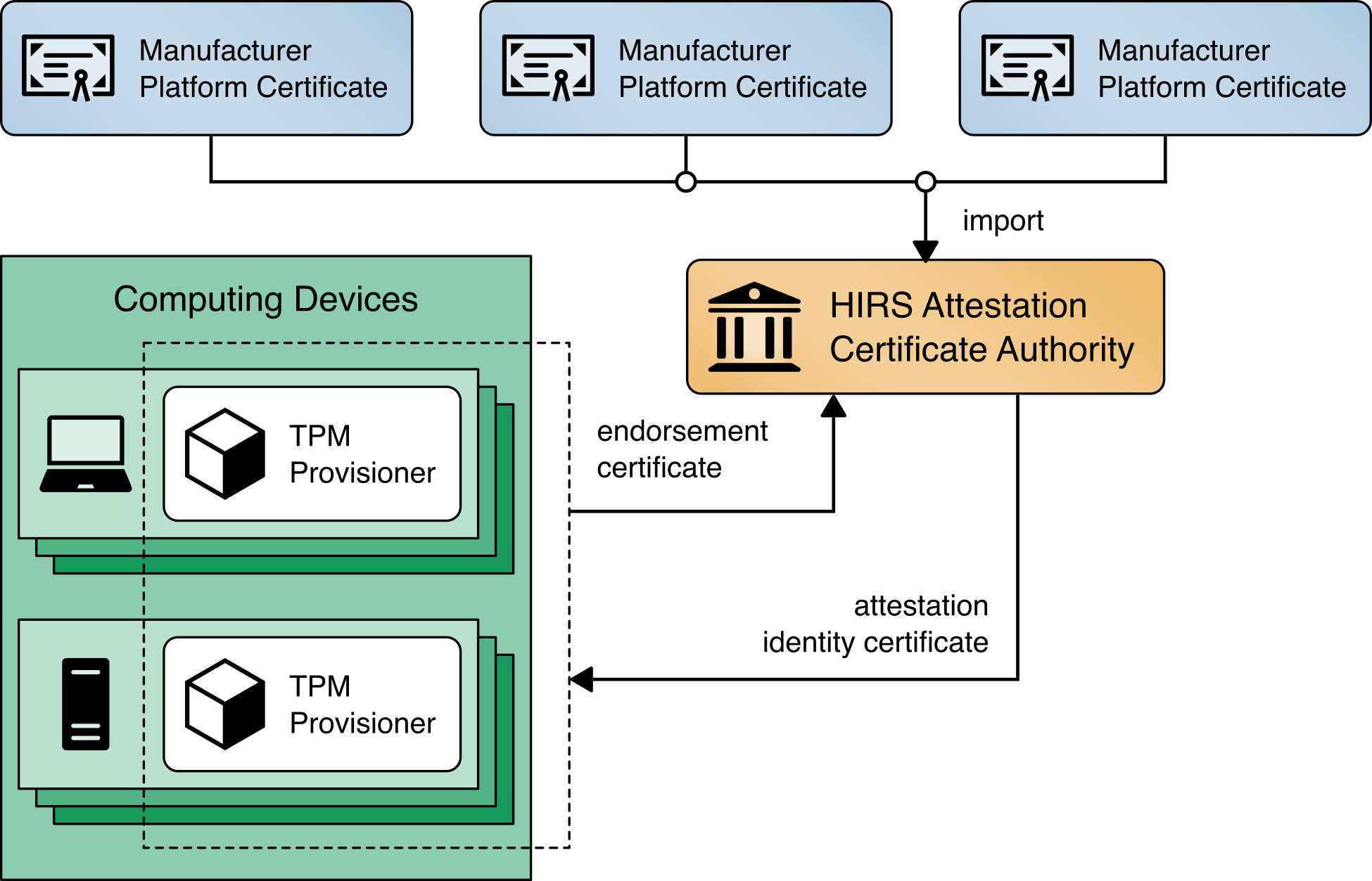
Figure 4‑3 presents a high-level view of how the HIRS system integrates with our prototype demonstration.
Figure 4‑3 HIRS ACA Platform
4.3.2 Network Boot Services
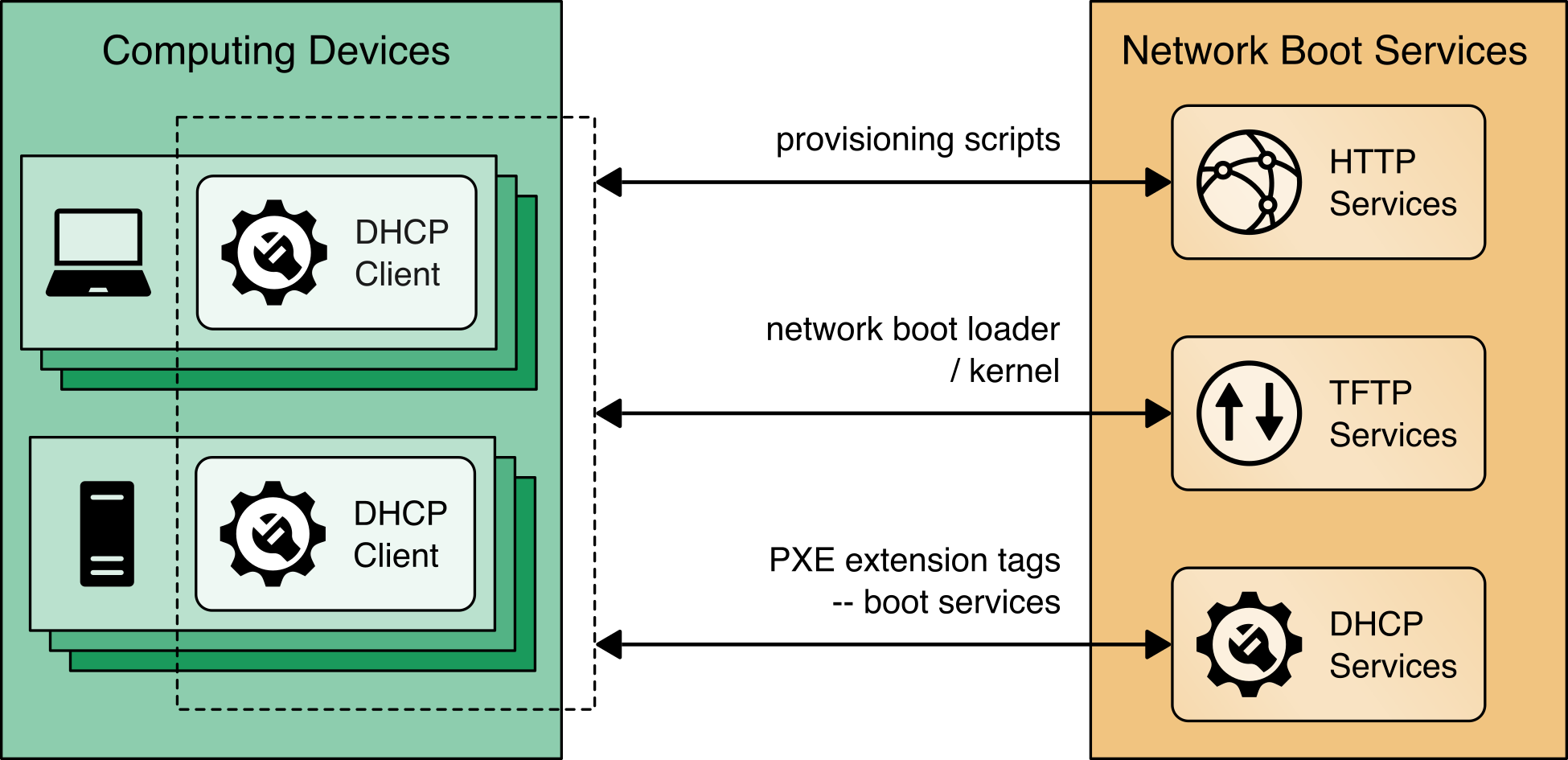
The computing devices in this prototype demonstration support a Dynamic Host Client Protocol (DHCP) based Preboot Execution Environment (PXE), which enables an IT administrator to boot the device over the network. In our environment, the IT administrator can boot into either a customized CentOS7 or a WinPE OS, depending on the platform validation tools that are needed. The CentOS7 environment supports the TPM Provisioner component of the HIRS ACA Platform, the Eclypsium Portable Scanner, and automation scripts. Figure 4‑4 details the flow of the boot environment:
Computing devices are configured to boot over the network via a network interface card (NIC). The DHCP server presents the boot options to the IT administrator. Once the OS is chosen, the DHCP server directs the DHCP client to the Trivial File Transfer Protocol (TFTP) server.
The DHCP client downloads and executes boot loaders and kernels associated with the target OS.
The IT administrator downloads the latest provisioning script from a centralized repository.
Figure 4‑4 Network Boot Services Environment
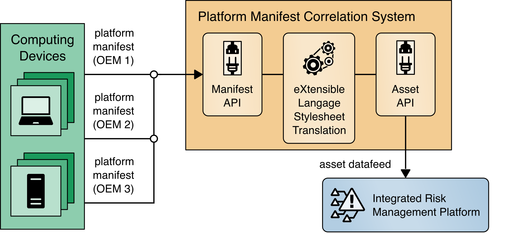
4.3.3 Platform Manifest Correlation System
This system assists in providing computing device manifest attributes to the asset management system. The system was built specifically for this demonstration and was built on open-source projects to include the node.js server platform. The requirements of this system were defined as:
Provide a web interface for the IT administrator to upload platform manifests.
Provide a REST API for scripts to upload platform manifests.
Provide a REST API for the asset management system to periodically poll for new computing devices to import in the repository.
Once the platform manifest is uploaded, it is converted to a common XML format that has been defined within the Archer platform console via eXtensible Stylesheet Language Translation (XSLT). XSLTs have been defined that support manifests from the HIRS ACA Provisioner, Intel’s TSC applications, HPE’s PCVT tool, Dell’s SCV tool, and HP Inc. custom scripts.
Figure 4‑5 presents how it is integrated into the larger architecture.
Figure 4‑5 Platform Manifest Correlation System
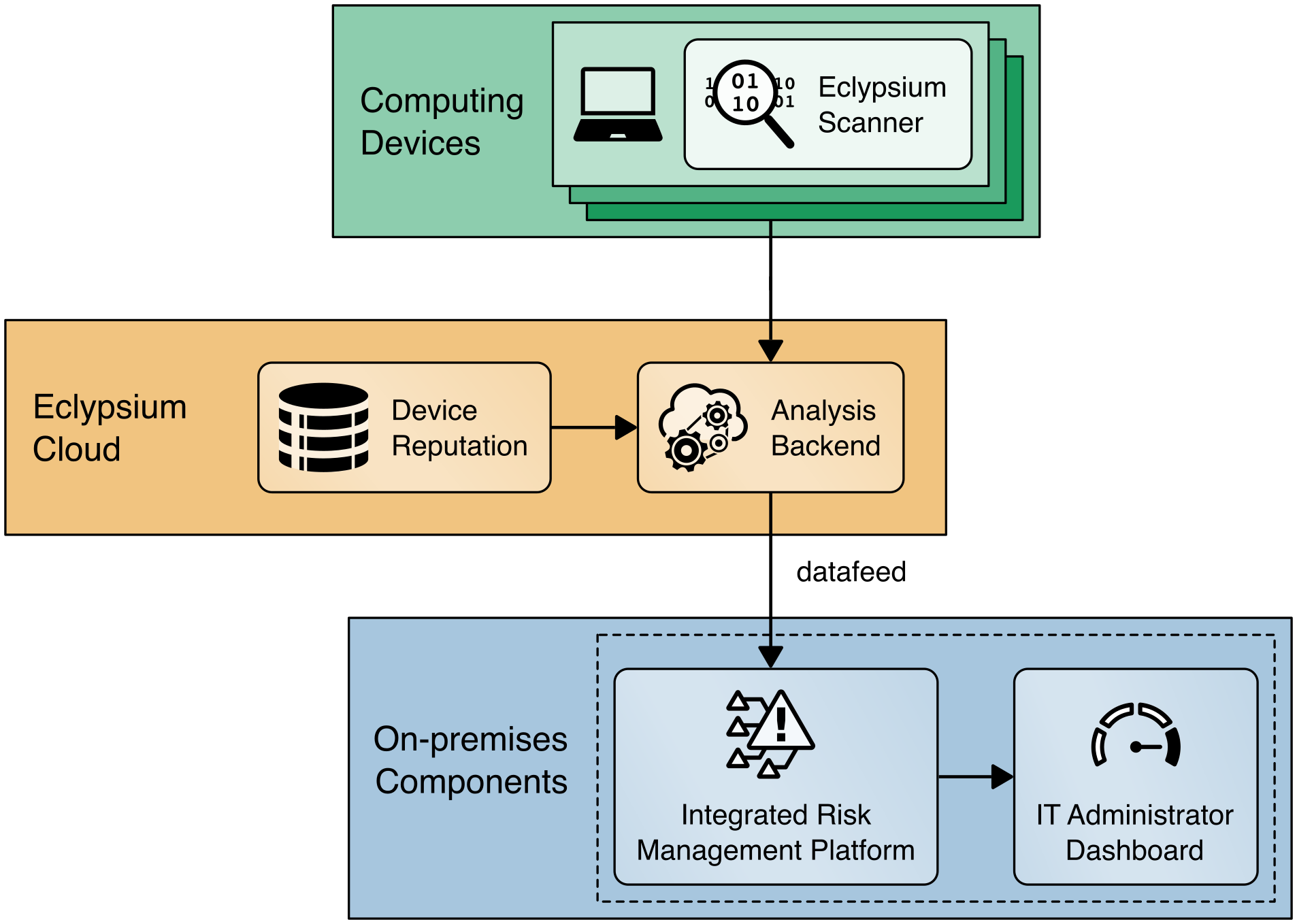
4.3.4 Eclypsium Analytic Platform
The Eclypsium Analytic Platform is a security solution that focuses on vulnerabilities and threats below the OS layer, to include firmware and component hardware. The platform consists of an endpoint agent, which can be deployed from an enterprise systems configuration manager on each computing device, the analysis backend (either cloud or on-premises), and the device reputation cloud service. The platform continuously updates a profile for each device and collects telemetry about each computing device into the analysis backend. The device reputation cloud provides a database of collected vulnerabilities that could potentially affect computing device components within an organization.
The user performs an initial endpoint agent scan of a computing device, which forms a baseline profile. The baseline is stored in the Analysis Backend and is used for later comparisons. Any deviations from the baseline are detected and can be communicated to an organization’s IT Security department as an integrity issue in multiple ways according to organization policy. For example, the IT Security department can be alerted when the system firmware version has changed from the baseline, which could indicate an unexpected firmware swap or tampering with the computing device in the operational environment. This prototype demonstration leverages a combination of Eclypsium’s REST API (Scenario 3—operational monitoring) and web-based dashboard captured in Figure 4‑6 (Scenario 2—provisioning of the computing device).
Figure 4‑6 Eclypsium Management Console
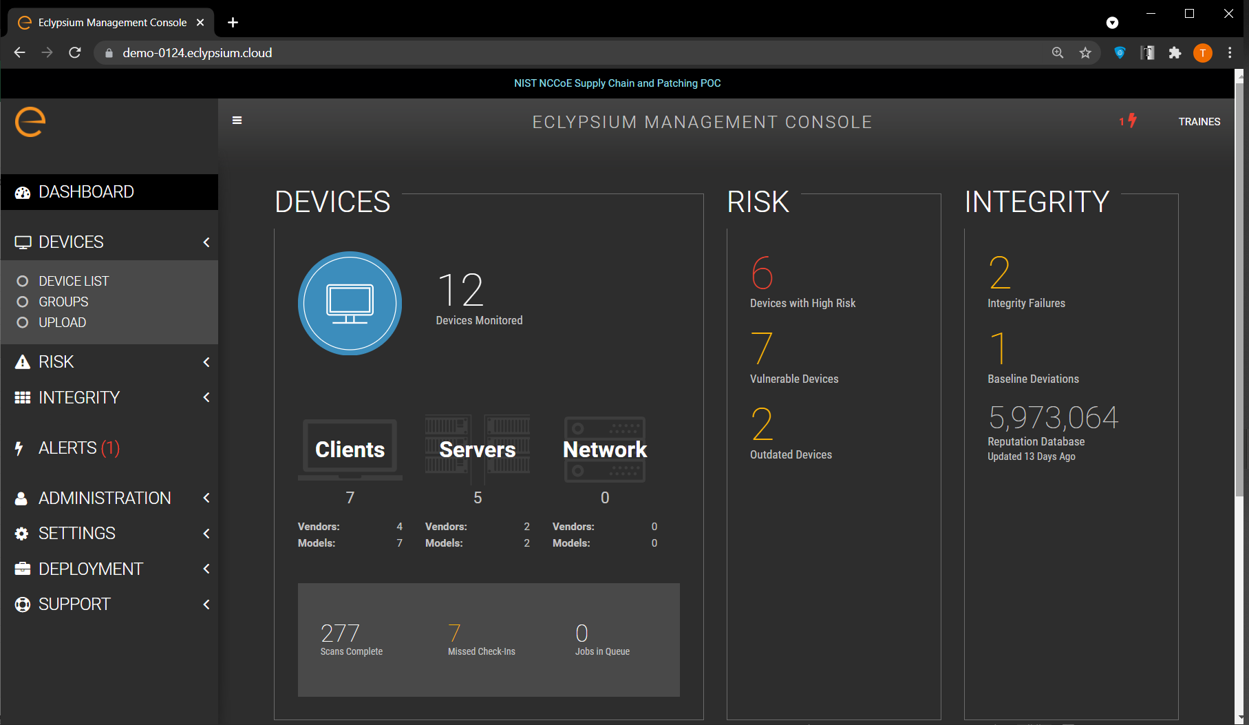
In Scenario 2, this demonstration uses a portable version of the Eclypsium agent, as opposed to the installer-based version used in Scenario 3. This is to support an ephemeral environment for the IT administrator where computing device acceptance testing is performed. We have integrated this portable version of the agent into the CentOS7 discussed in Section 4.3.2.
The Eclypsium Analytic Platform also supports a disconnected deployment, where the computing devices that are continuously monitored by the Eclypsium agent communicate directly with an on-premises analytics backend. This type of deployment is useful for environments where a computing device, such as a datacenter server, has restricted network access due to an organization’s security posture. We demonstrate this use case using the servers contributed to the project (Sections 4.4.3 and 4.4.4), and it is represented in Figure 4‑7.
Figure 4‑7 Eclypsium Analytic Platform Server Implementation
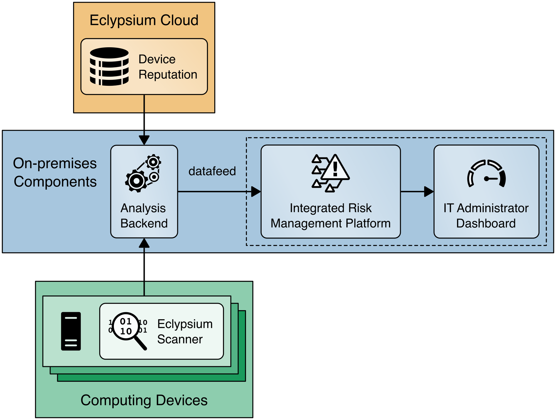
Figure 4‑8 presents how this project integrates Eclypsium’s cloud services into the demonstration architecture for laptops.
Figure 4‑8 Eclypsium Analytic Platform Laptop Implementation
4.4 Computing Devices
In this prototype demonstration we define a computing device as client and server devices associated with verifiable artifacts. These devices may contain several integrated platform components or subsystems from multiple manufacturers. Our manufacturing partners, HP Inc., Dell Technologies, Hewlett Packard Enterprise, Seagate, and Intel have contributed hardware to the project.
4.4.1 HP Inc.
HP Inc. functions as an OEM within this prototype demonstration and contributed two HP Inc. Elitebook 360 830 G5 laptops. Each laptop has a TCG-Certified TPM v2.0 with embedded Endorsement Key (EK) Certificate.
In the first phase of this project, in support of Scenario 1 the NCCoE lab utilized the HIRS Platform Attribute Certificate Creator (PACCOR) project to generate a representative Platform Certificate bound to the device identity. The Platform Certificate was signed by HP Inc.’s internal test CA. In the project’s second phase, the NCCoE worked with the HP Inc. technical team to have a demonstration laptop with a Platform Certificate embedded on the device, resulting in a process that aligns with the desired outcome of Scenario 1—a manufacturer-created verifiable artifact.
In support of Scenario 2, acceptance testing of the HP Inc. laptops is performed via the HIRS ACA TPM Provisioner described in Section 4.3.1.
In support of Scenario 3, the demonstration is utilizing Microsoft Endpoint Configuration Manager integrated with the HP Client Management Script Library (CMSL) PowerShell scripting library for enterprise manageability of platform hardware and firmware security capabilities (e.g., firmware integrity breach detection and physical tampering detection). As described in Section 4.2.1, this demonstration makes use of HP Inc.’s CMSL PowerShell modules. Specifically, the BIOS and Device module provides basic querying of device attributes and secure manipulation of HP Basic Input/Output System (BIOS) settings and managing the HP BIOS, while the Firmware module provides functionality for interfacing with the HP BIOS firmware, such as gathering security-related events from the HP Endpoint Security Controller hardware.
Finally, this demonstration utilizes HP Inc. capabilities that augment tooling used to verify the integrity of computing device components during use. These capabilities are intended to be provisioned during the computing device acceptance testing process before issuance to the end user for operational use and can optionally be provisioned in manufacturing and included in the device acceptance testing process.
HP Sure Admin enforces a certificate-based authorization model that enables firmware setting security management by an IT administrator. The model is composed of two keys, an Endorsement Key and a Signing Key (note: the Endorsement Key in this context is not related to the TPM Endorsement Key). The Endorsement Key’s primary purpose is to protect against unauthorized changes to the Signing Key. The Signing Key is used by the platform to authorize commands sent to the firmware (BIOS) [B14] [B15].
HP Sure Start is a built-in hardware security system that protects platform firmware code and data (including HP BIOS, HP Endpoint Security Controller firmware, and Intel Management Engine firmware) from accidental or malicious corruption by (1) detecting corruption and then (2) automatically restoring the firmware to its last installed HP-certified version and the data (settings) to the last authorized state. The capability also stores events related to firmware integrity that can provide visibility into attempted firmware integrity breaches [B16].
HP Sure Recover is an OS recovery mechanism that is completely self-contained within the hardware and firmware to allow secure OS recovery from the network or from a local OS recovery copy stored in dedicated flash on the system board. It includes settings that control when, how, and from where BIOS installs the OS recovery image, and which public keys are used by BIOS to validate the integrity of the recovery image. It can also record events due to OS recovery image integrity failures [B16].
HP TamperLock provides a general protection mechanism against classes of physical attacks that involve removal of the system cover to obtain access to the system board. This is achieved by providing a cover removal sensor to detect and lock down a system that has been disassembled, along with fully manageable policy controls to configure what action to take in the event a cover removal is detected. Cover removal events and history are stored in platform hardware and can be queried via CMSL PowerShell commands [B17].
The HP Endpoint Security Controller is HP’s hardware root of trust that enables all the features above and provides isolated/dedicated non-volatile storage on the system board that (1) enables recovery of firmware code and data, policies, and OS images, as well as (2) provides secure hardware-based storage for tampering-related events associated with each of the capabilities described above.
4.4.2 Dell Technologies
Dell contributed hardware and supporting software as part of a pilot program that are aligned with the defined security characteristics of this prototype demonstration.
4.4.2.1 Laptops
The demonstration uses four Dell Latitude laptops as the client computing devices that are evaluated through an enterprise acceptance testing process. These computing devices are equipped with a TPM that is compatible with the TCG’s 2.0 specification as discussed in Section 3.6.1. In alignment with the TCG specifications, the TPM endorsement keys were generated by Nuvoton, a supplier of TPMs to OEMs.
In support of Scenario 1, Dell supplied the NCCoE with the infrastructure and tooling to support TCG Platform Certificate generation during Dell computing device manufacturing. Once executed, the tooling collected the computing devices component data and created a Platform Certificate. The Platform Certificate was bound to the device identity (TPM) and digitally signed by a Dell factory Hardware Security Module. The Platform Certificate was stored within the Extensible Firmware Interface (EFI) system partition, where it was later extracted for use in supporting platform integrity validation systems.
In support of Scenario 2, the validation of component authenticity during acceptance testing of the Dell laptops was performed via the HIRS ACA TPM Provisioner described in Section 4.3.1.
Dell contributed the Dell Trusted Device (DTD) platform to the project in support of Scenario 3. Among other capabilities, DTD can detect indicators of hardware attack, which can alert a security operator that a remediation action is required. The DTD platform uses an agent which is installed on the client laptop and a cloud analysis engine hosted by Dell Technologies.
4.4.2.2 Servers
Dell also contributed an R650 PowerEdge server to the demonstration. The R650 along with the PowerEdge portfolio of servers can be shipped with the Secured Component Verification (SCV) feature, which is used to ensure that the server was delivered exactly as it was built at the factory. As part of this capability, an organization can place an order for a customized server, where it is built to their specification. After assembly the server’s component data is collected and the Dell Remote Access Controller (iDRAC) is leveraged to create cryptographic keys which are protected by the iDRAC Hardware Root of Trust, to create the x509 Certificate that is then signed by the Dell Manufacturing Certificate Authority. The x509 Certificate (SCV Certificate) that is stored in iDRAC is validated prior to shipment from factory.
SCV provides a strong cryptographic platform identity that is not only bound to the platform’s unique hardware but also to Dell’s possession of that hardware during assembly due to the creation process requiring the unique hardware to cryptographically sign the Certificate Signing Request (CSR). At the core of the SCV platform is the SCV command-line verification application, which performs the following functions without internet or intranet connectivity:
Downloads SCV Certificate that is stored in the iDRAC via SCV Validation Tool.
Validates the SCV Certificate signature is valid and has not been tampered with
Verifies the SCV Certificate Chain of Trust to ensure it chains back to the Dell SCV Root Certificate Authority
Cryptographically challenges iDRAC for possession of the platform-unique SCV private key to ensure the platform matches the SCV Certificate
Any error in SCV Certificate signature verification, chain of trust verification, or proof of possession will result in a Fail output before component data is compared or trusted.
Interrogates the system to obtain the current inventory and iDRAC Hardware ID Certificate, and collects the TPM Endorsement Key Certificate Serial Number.
Compares current system inventory against the manifest in the Platform Certificate, including the cryptographic identities for the iDRAC Hardware ID Certificate and the TPM Endorsement Key Serial Number
Any swapping or removal of the components that are captured in the certificate will be identified as a Mismatch in the SCV application output. An additional detailed log is created describing all the components which were expected (present in factory) versus what has been detected (currently present in platform).
The Trusted Platform Module (TPM) Endorsement Key (EK) and iDRAC Hardware ID Certificate as represented in the signed SCV Certificate can then be used as permanent cryptographic identities for the life of the PowerEdge platform in addition to the SCV Certificate.
4.4.3 Intel
Intel contributed hardware, supporting software, and cloud services that are aligned with the defined security characteristics of this prototype demonstration through its Transparent Supply Chain (TSC) platform [B18]. TSC enables organizations to verify the authenticity and firmware version of systems and their components. The remainder of this section summarizes the TSC components used within this prototype demonstration; however, it is not an exhaustive description of the complete platform. Refer to Intel’s TSC website for complete documentation.
The TSC process starts at the OEM, where an Intel-provided tool called TSCMFGUtil enables the creation of a Platform Certificate data file that is compliant
with the TCG Platform Certificate Profile Specification Version 1.1. The TSCMFGUtil also generates the Direct Platform Data (DPD) file capturing the Platform
Snapshot before shipping the platform out to the customer. The Platform Certificate data file contains TPM information such as the Platform Configuration
Registers (PCRs), the TPM Serial Number, and the TPM Endorsement Key. The DPD file contains information about the components within the computing device such as
component manufacturer part number, batch number, and serial and lot number, as well as sourcing information. The OEM then uploads these files to Intel’s Secure
File Transport Protocol (SFTP) site where they are processed and digitally signed.
Next, after the computing device is purchased by an organization’s IT department, an administrator downloads the DPD file and Platform Certificate from the
Transparent Supply Chain Web Portal as part of the computing device acceptance testing process. The aforementioned files are processed by Intel software
intended for the end customer, the AutoVerifyTool. In this prototype demonstration, we use the AutoVerifyTool with our demonstration laptops to enable the
following capabilities for the IT administrator:
The
ScanSystemfunction initiates the scanning of the system components and the TPM information. The scanning operation will perform the following operations:Read the following platform components: BIOS, system, motherboard, chassis, processor, dual in-line memory modules (DIMMs), batteries, Intel Active Management Technology firmware version, power supplies
Read the TPM PCRs, public Endorsement Key, and the Endorsement Key serial number
Read the internal drive information
Read the Windows Management Instrumentation (WMI) Information for internal keyboard, pointer, and network devices
After the system has been scanned, the IT administrator executes the
Read Direct Platform Data Filefunction which opens and displays the DPD associated with the platform.The IT administrator executes the
Comparefunction, which compares the current system component value information that was captured byScanSystemoperation to the component value information that was read in from the DPD file.The IT administrator executes the
Platform Certificate Verifyfunction, which validates the Platform Certificate issued for the platform using the TPM as the hardware root of trust. ThePlatform Certificate Verifywill check that the TPM Endorsement Key serial number matches the Endorsement Key serial number in the Platform Certificate. The function will also check that the manufacturer, version, and serial number match the values in the Platform Certificate.
In addition to the AutoVerifyTool, Intel provided a similar utility named TSCVerifyUtil that has the same capabilities but is intended to be executed from the command line on Windows and Linux systems. The TSCVerifyUtil is well-suited for automated scripts that run continuously without administrator intervention. We have used TSCVerifyUtil to demonstrate acceptance testing on server platforms and continuous monitoring for laptops.
To demonstrate the TSC platform, Intel contributed laptop computing devices from OEMs Lenovo and HP Inc. (T490 Thinkpad and HP EliteBook x360 830 G5, respectively) and a server based on an Intel S2600WT family server board. Intel also provisioned accounts for the NCCoE project team to use the TSC Web Portal for demonstrating computing device acceptance testing described in Scenario 2.
4.4.4 Hewlett Packard Enterprise (HPE)
HPE contributed hardware and supporting software that are aligned with the defined security characteristics of this prototype demonstration through its HPE Trusted Supply Chain program. The HPE demonstration server’s platform integrity is validated using the HPE-developed open-source Platform Certificate Verification Tool (PCVT) [B19], leveraging a hardware root of trust (TPM) via TCG Platform Certificate specifications. Our demonstration used an HPE Proliant DL360; however, an implementer of this guide should consult the HPE website for the current roster of servers that support the capabilities described below.
In our demonstration server, the HPE Platform Certificate and trusted root certificate was provisioned during the manufacturing process in secure storage and digitally signed by an HPE demonstration CA. This enables an offline or “air-gapped” use case for server platform integrity verification. In addition to Platform Certificates, the HPE demonstration implements system Device Identity (IDevID) certificates as a TCG-defined method for platform identity cryptographic attestation via the TPM.
The PCVT enables an organization to ensure that the shipped server configuration matches the configuration from the factory using the following tests:
Ensures the validity of the trust chain and signature of the factory installed initial DevID signing key and initial Attestation Key (IAK) created by HPE. The initial DevID is a unique, permanent cryptographically protected identifier for the HPE server. The IDevID certificate is TCG and IEEE 802.1 AR compliant. The IAK is a restricted signing key that is used when performing remote attestation of the HPE server using its TPM.
Performs TCG certificate trust chain verification, verifying the chain from the signed certificate to the HPE Root CA certificate. This step verifies the certificate signature against the intermediate certificate that signed the Platform Certificate, system IDevID certificate, and associated system IAK Certificate.
Verifies the demonstration server’s hardware manifest against the Platform Certificate that HPE issued at its manufacturing facility.
The PCVT is available via the HPE GitHub repository as a bootable optical disc image (ISO) that an administrator can run via HPE server management tools, which is documented in PCVT’s User Guide. However, in our demonstration we created a customized acceptance testing environment based on CentOS 8. This environment incorporated a compiled version of the PCVT with additional scripts that provision the server into the enterprise asset management and discovery system upon successful execution of the PCVT.
4.4.5 Seagate
Seagate contributed three Exos 18 Terabyte Hard Drives delivered in a 2U12 enclosure. We demonstrated how an organization could verify the drives are genuine Seagate products through two capabilities—Secure Device Authentication and Firmware Attestation. Both capabilities are facilitated via the TCG Storage API (GitHub repository), which we utilized in an integration with Intel TSC platform integrity tools. Secure Device Authentication (SDA) and Firmware Attestation in conjunction provide cryptographically assured methods to trace the drive and firmware to the manufacturer (Seagate). Both features are certificate-driven and verifiable by way of Seagate’s root certificate from its internal CA.
As noted above, both capabilities are available via API, and Seagate has published a command-line utility via GitHub to demonstrate interacting with the drive. The command-line utility provides a roadmap that organizations can use to strengthen and expand platform integrity verification use cases. To illustrate a use case in this demonstration, we connected the Seagate enclosure to our Intel-contributed server. An enterprise may use a server-connected drive enclosure to increase the storage capacity of critical applications hosted in a datacenter. This organization prioritizes the integrity of the data, and by extension the integrity of the drive itself. Therefore, the validation of the server platform integrity—to include measurements from the attached drives—mitigates the risk of an integrity-related breach to an acceptable level.
With the scenario described above in mind, Seagate, in collaboration with Intel developers, integrated Transparent Supply Chain validation utilities with the Seagate drive APIs. As a result, this integration enables an implementing organization to simultaneously derive the benefits of TSC tooling described in Section 4.4.3 and verify drive integrity measurements with one command. The process of Secure Device Authentication (SDA) and Firmware Attestation is illustrated in Figure 4‑9.
Figure 4‑9 Seagate Secure Drive Authentication Integration
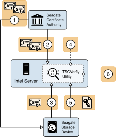
During the manufacturing process, Seagate creates a Trusted Peripheral signing certificate (tperSign Certificate) and Attestation Certificate (tperAttestation Certificate) that are signed by the Seagate Intermediate CA. The tperSign Certificate and tperAttestation Certificate are stored in the drive’s firmware. The drive is now capable of responding to challenges from host computing devices.
The host, in this case the Intel server, stores the Seagate Root and Intermediate CA certificates in the TSCVerifyUtil application binary. They are used later in the validation process.
The Security Operator executes the TSCVerifyUtil application and directs it to initiate the SDA verification. The drive’s certificate is returned in the initial invocation of SDA.
The drive’s signing certificate is returned to TSCVerify where it is validated against the Seagate Root and Intermediate CA certificates. If validation succeeds, the process continues.
TSCVerifyUtil generates a challenge (timestamp) that is transmitted to the drive. The drive returns a cryptographically signed response based on the challenge.
TSCVerifyUtil verifies the digital signature on the response with the drive’s public key retrieved in Step 3.
Upon the successful completion of the SDA process, Seagate’s Firmware Attestation capability is exercised. The Firmware Attestation process is illustrated in Figure 4‑10.
Figure 4‑10 Seagate Firmware Attestation Integration
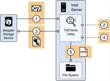
TSCVerifyUtil requests the tperAttestation Certificate from the drive. The certificate path is validated against the Seagate Intermediate and Root CAs.
TSCVerifyUtil generates an Assessor Identifier and a nonce. The Assessor Identifier is a static host server identifier (such as the hostname) and the nonce is a randomly generated set of 16 bytes for each invocation of the firmware attestation method. These values, in addition to the common name of the tperAttestation Certificate, are stored for the next step.
The values from Step 2 are transmitted to the drive via the Get Signed Firmware Message command and the response is returned.
The digital signature on the response is verified using the drive’s public key from the tperAttestation Certificate retrieved in step 1.
If Step 4 succeeds, the associated firmware hashes are exported from TSCVerifyUtil as a JSON-formatted file.
The firmware attestation outputs multiple integrity measurement values, which in isolation give the verifier information about the current running version of the drive firmware. Ideally, measurements are compared against a manufacturer-published baseline set of integrity measurements for the drive which are known by the verifier before the attestation is produced. For the purposes of this demonstration, the measurements produced by the firmware attestation capability were validated against values that were communicated to the project team and incorporated into the TSCVerifyUtil.
5 Security Characteristic Analysis
The purpose of the security characteristic analysis is to understand the extent to which the project meets its objective of creating a prototype that demonstrates how organizations can verify that the components of their acquired computing devices are genuine and have not been tampered with or otherwise modified throughout the devices’ life cycles. In addition, it seeks to understand the security benefits and drawbacks of the prototype solution.
5.1 Assumptions and Limitations
The security characteristic analysis has the following limitations:
It is neither a comprehensive test of all security components nor a red-team exercise.
It cannot identify all weaknesses.
It does not include the lab infrastructure. It is assumed that devices are hardened. Testing these devices would reveal only weaknesses in implementation that would not be relevant to those adopting this reference architecture.
5.2 Build Testing
This section addresses how this prototype demonstration addresses each scenario and identifies gaps that will be addressed as the project progresses.
5.2.1 Scenario 1
The desired outcome of Scenario 1 is the creation of verifiable platform artifacts, either by the manufacturer or the customer in the field. In the case of Intel laptops, this demonstration uses a manufacturer-created platform artifacts by way of Intel’s Transparent Supply Chain platform (Section 4.4.3).
In the first phase of this project, we emulated a customer-created platform artifact using the HIRS ACA project’s PACCOR software for Dell and HP Inc. laptops. In the second phase, Dell and HP Inc. contributed laptops with pre-installed verifiable artifacts created at the factory, where they were signed by manufacturer-specific certificate authorities as opposed to NCCoE-generated authorities. Additionally, Dell made their root certificate publicly available to those customers who participate in this pilot program.
The Platform Certificates are subsequently stored in the laptop’s EFI partition where they are accessible to the customer for validation, in alignment with the TCG’s PC Client Platform Firmware Integrity Measurement specification which defines the Platform Certificate format, naming convention, and common directory location when stored locally on the laptop. In this demonstration, we simulate the process of an IT administrator taking delivery of the laptops by accessing and uploading the Dell and HP Inc. verifiable artifacts to the HIRS ACA validation system for use in Scenarios 2 and 3.
The server contributed by Intel uses the same TSC platform as the laptops to deliver platform artifacts to the customer. HPE servers that support platform artifacts are generated at the factory (Section 4.4.4) and are available to the customer via the Integrated Lights-Out API. Dell server platform artifacts are generated at the factory through the Secure Component Validation program (Section 4.4.2).
In all cases, the platform artifact is instantiated as a Platform Attribute Certificate defined in the TCG Platform Attribute Credential Profile Specification version 1.0. The profile defines structures that extend the X.509 certificate definitions to achieve interoperability between platform validation systems that ingest artifacts. Figure 5‑1 shows the relationship between the Platform Certificate and the TPM Endorsement Credential, based on a graphic from the TCG Credential Profiles for TPM [B20].
Figure 5‑1 Platform Certificate Binding to Endorsement Credential
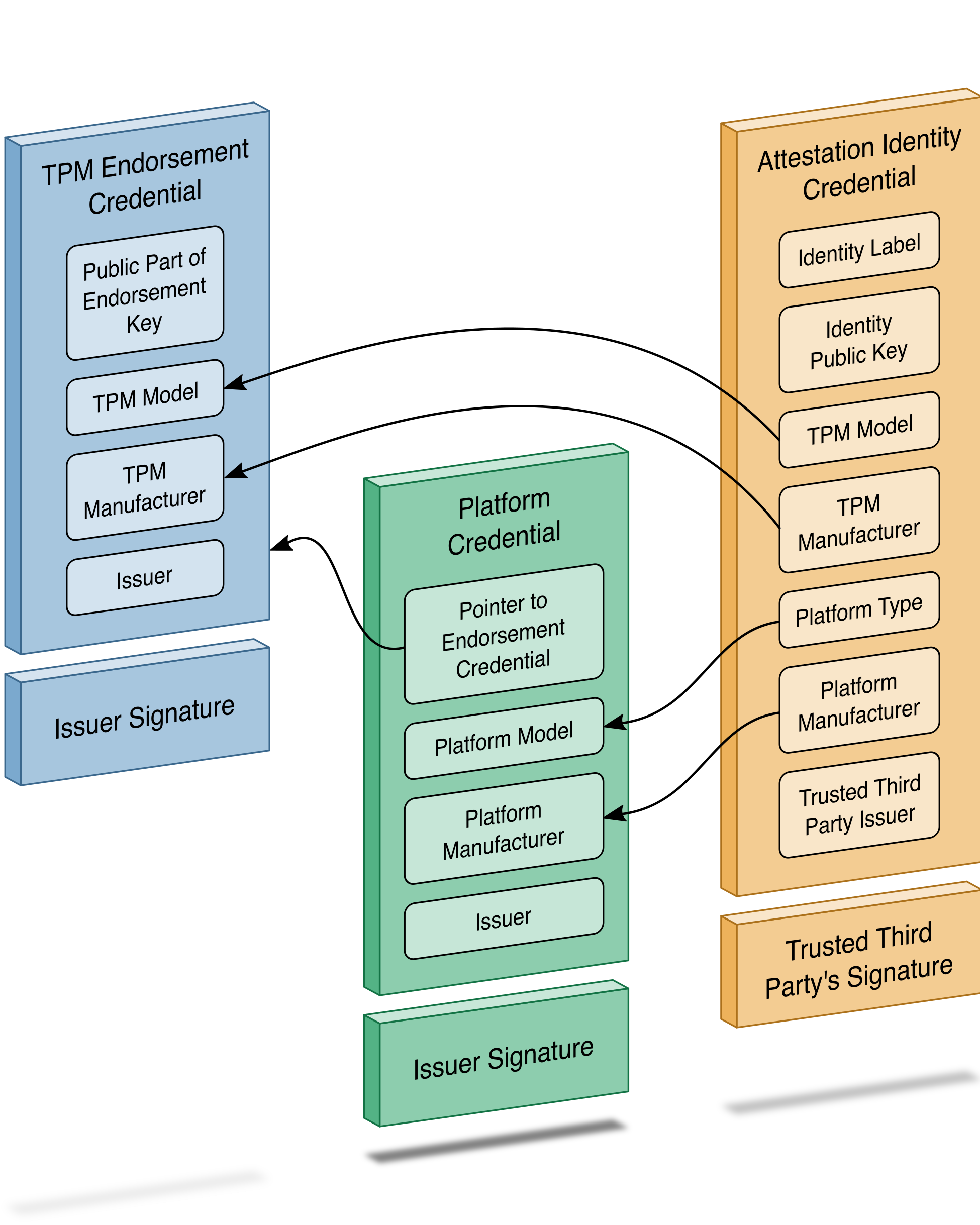
Below, we use an open-source tool (openssl) to parse one of our demonstration platform artifacts to validate alignment with the TCG specification. Note that the current profile allows the manufacturer to choose between Attribute Certificate or Public Key Certificate format. The example in Table 5‑1 uses the Attribute Certificate format and is not an exhaustive comparison of all requirements within the profile. It is intended to highlight the binding of authoritative attributes (Attribute Extension) to the hardware itself (Holder).
Table 5‑1 Demonstration Verifiable Artifact
Platform Certificate Assertion |
Field Name |
Field Description |
|---|---|---|
C=US, ST=California, L=Palo Alto, O=HP Inc., OU=HP Labs Pilot, CN=HP Inc. NCCOE-Test |
Issuer |
Distinguished name of the Platform Certificate issuer |
C=DE, O=Infineon Technologies AG, OU=OPTIGA(TM), CN=Infineon OPTIGA(TM) TPM 2.0 RSA CA 042 |
Holder |
Identity of the associated TPM EK Certificate |
2.23.133.18.3.1 |
Component Class Registry |
Example Component Identifier |
00020001 |
Component Class Value (Chassis) |
|
HP |
Component Manufacturer |
|
10 |
Component Model |
In addition to a Platform Certificate, a manufacturer may implement IDevID and IAK certificates as complementary capabilities. This is demonstrated by our HPE server with the PCVT described in Section 4.4.4. As noted above, Platform Certificates are defined as attribute certificates without a key. IDevID certificates are defined by TCG’s TPM 2.0 Keys for Device Identity and Attestation [B21], and its purpose is to bind a key to a device’s TPM using carefully constructed protocols that align with TCG specifications. TCG IDevID certificates provide evidence that a key belongs to a specific computing device by binding that key to the device’s TPM. Further, the private key associated with the IDevID certificate is created such that it cannot be exported from the TPM. Applications, such as network onboarding, can leverage the IDevID certificate for automated provisioning.
This prototype demonstrates only the validation of IDevID certificates via HPE’s Platform Certificate Validation Tool. Interested readers should follow the progress NCCoE’s Trusted Internet of Things (IoT) Device Network-Layer Onboarding and Lifecycle Management project and/or review the Trusted Internet of Things (IoT) Device Network-Layer Onboarding and Lifecycle Management (Draft) White Paper [B22] for an in-depth discussion of device identity use cases.
Finally, the Trusted Peripheral (TPer) signing certificates that are embedded in the Seagate drive firmware serve as verifiable artifacts in this demonstration. These certificates support the Secure Device Authentication and Firmware Attestation capabilities, and attributes in the certificates are used to uniquely identify the drive. Table 5‑2 identifies these attributes.
Table 5‑2 Seagate Drive Verifiable Artifacts
Seagate Drive Certificate Assertion |
Field Name |
Field Description |
|---|---|---|
CN=ZR5056HD, OU=DriveTrust, O=Seagate Technology, C=US |
Subject |
Distinguished name of the Seagate drive device certificate |
SN=ZR5056HD |
Subject Alternative Name |
Alternative name of the Seagate drive device certificate |
C=US, O=Seagate Technology LLC, OU=Seagate Technology TDCI, CN=Seagate Technology TPer Attestation [022300085000C500CAD93EA3] |
Subject |
Distinguished name of the Seagate firmware attestation certificate |
5.2.2 Scenario 2
The desired outcome of Scenario 2 is to verify the provenance and authenticity of a computing device that has been received through non-verifiable channels. The project description defined four notional steps that an IT administrator might perform to augment, not replace, an existing asset management acceptance testing process. We recommend the implementer perform acceptance testing within a quarantine network or, in case of a zero-trust deployment, the newly introduced computing device is isolated until it has passed the validation. The remainder of this section discusses the status of each step, with supplemental sequence diagrams available in Appendix C and in our online repository.
Step 1:As part of the acceptance testing process, the IT administrator uses tools to extract or obtain the verifiable platform artifact associated with the computing device.
Using the Intel Transparent Supply Chain platform, an IT administrator obtains the verifiable artifact for compatible laptops and servers from the download portal in one of two ways—manually via the web interface, or programmatically through the download portal API, depending on the organizational use case. In our lab, we demonstrated a manual process where an IT administrator uses a web browser to access the Intel download portal, input the computing device serial number, and download the associated verifiable artifacts. The download portal API may be useful for organizations that have an automated computing device acceptance testing process. The download portal screenshot in Figure 5‑2 provides a visual of the interface viewed from the IT administrator’s perspective.
Figure 5‑2 Intel Transparent Supply Chain Download Portal
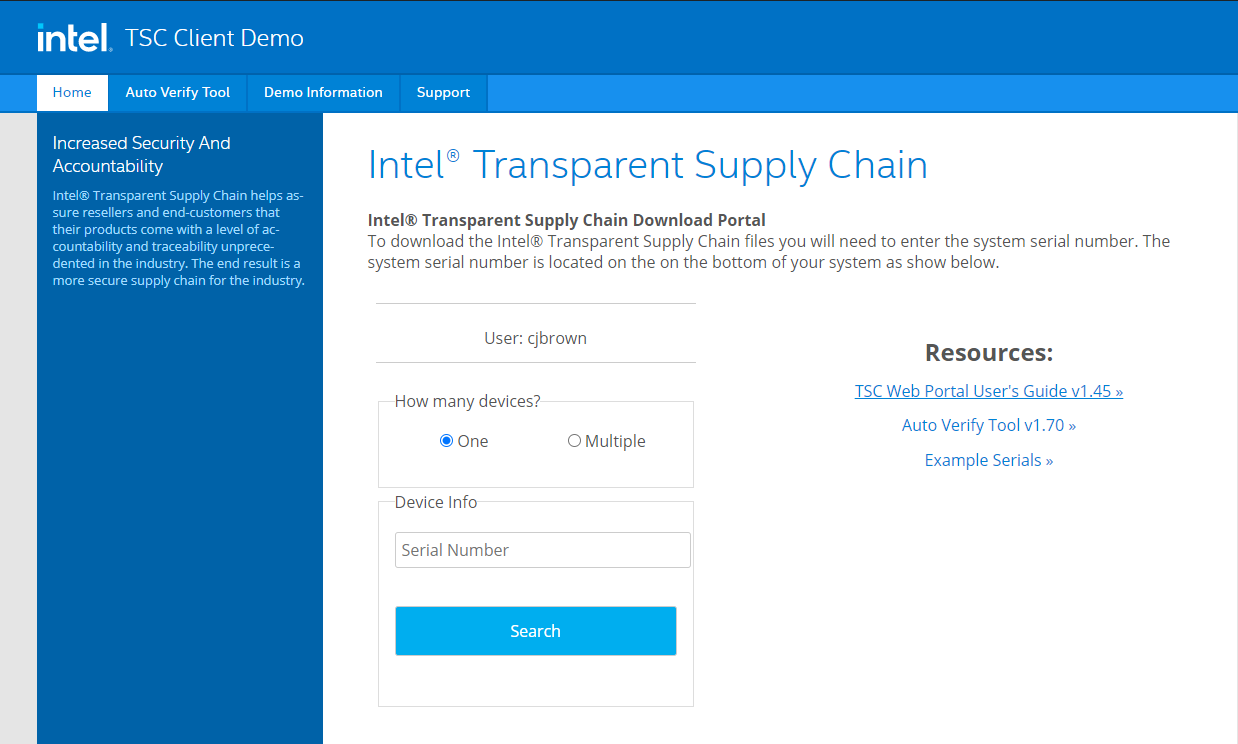
In this prototype demonstration for the Dell and HP Inc. laptop platforms, the IT administrator obtains the platform verifiable artifact from the EFI system partition storage (ESP). The ESP provides a convenient storage mechanism because it is available by all manufacturers that support Unified Extensible Firmware Interface (UEFI) and is OS-independent. Therefore, it is accessible either through our Linux network boot environment or the native OS (Windows 10). Alternatively, the verifiable artifact can be delivered to the IT administrator through an out-of-band process or stored directly on the TPM, if available on the computing device.
For the Dell and HPE server platforms, the verifiable artifact is extracted using via the SCV and PCVT tools, respectively.
Step 2:The IT administrator verifies the provenance of the device’s hardware components by validating the source and authenticity of the artifact.
Step 3:The IT administrator validates the verifiable artifact by interrogating the device to obtain platform attributes that can be compared against those listed in the artifact.
For simplicity, we have combined discussion of steps 2 and 3 because they are performed in tandem using platform validation tools.
In the Intel TSC platform, we execute the AutoVerifyTool described in Section 4.4.2 to verify the provenance of the device’s hardware
components in the native Windows 10 environment using the verifiable artifact retrieved from Step 1. The tool is preconfigured with trusted manufacturer signing
certificates that are used in the validation process. Second, the IT administrator scans the machine using the AutoVerifyTool, where the results are compared
against those listed in the artifact. The tool subsequently gives the IT administrator a visual indicator of whether or not the validation process was
successful. The tool can be accessible to the IT administrator in several ways, depending on the existing acceptance testing process. For this prototype, the
tool is available to the IT administrator via a network share accessible to IT staff with sufficient privileges.
In this prototype demonstration for the Dell and HP Inc. platforms, prior to the acceptance testing process, the IT administrator supplies the verifiable artifact’s (Platform Certificate’s) root (and potentially intermediate) CA certificates to the HIRS ACA portal to form a chain used later in the validation process. This process is repeated for the endorsement credential issuing certificates. We recommend that readers of this guide contact their specific manufacturer to retrieve the correct certificate chain to reduce the risk of false-negative validation failures.
Next, the IT administrator boots the target computing device into the ephemeral Linux CentOS7 environment described in Section 4.3.2 where the HIRS ACA Provisioner component is installed. Here, the IT administrator runs a script where the Provisioner is invoked, and the provenance of the device’s hardware components is verified by the HIRS ACA backend component. The IT administrator confirms validation of the verifiable artifact by observing the output of the script and optionally accessing the HIRS ACA portal web interface, as shown in Figure 5‑3. The checkmark in the Result column indicates the verifiable artifact has been validated and the assertions made by the artifact have been validated against the interrogation process.
Figure 5‑3 HIRS ACA Validation Dashboard
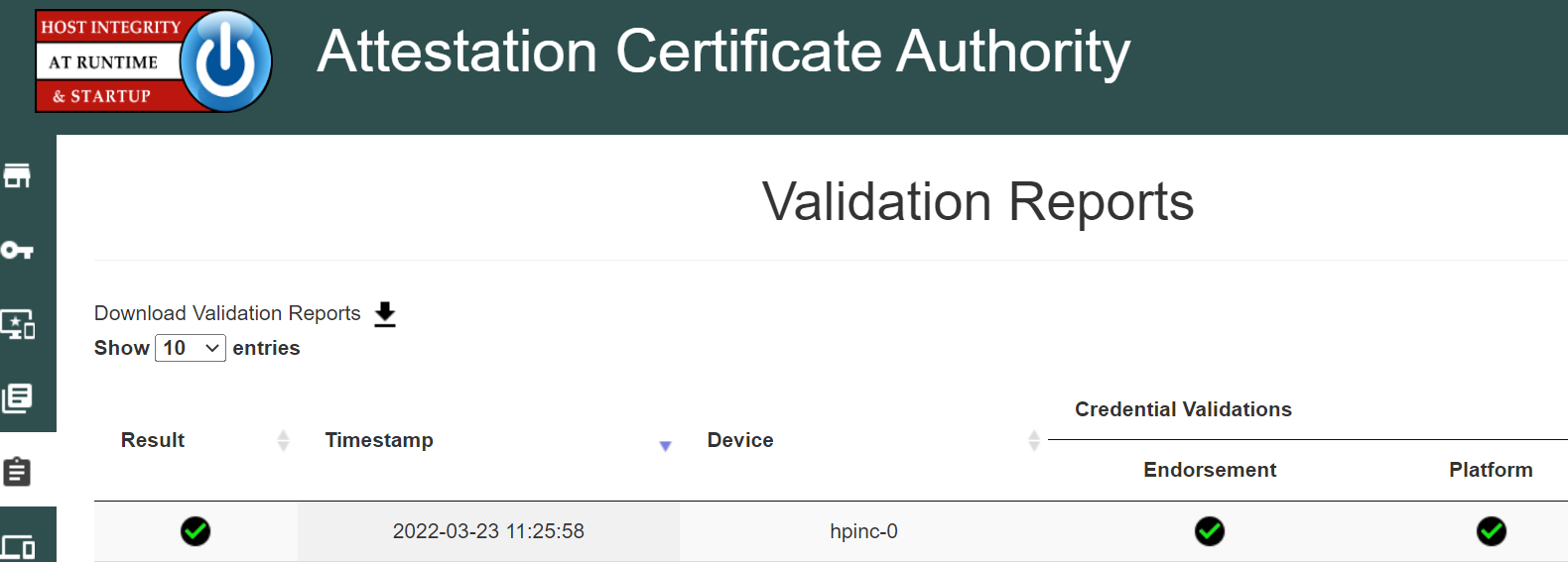
Finally, in addition to the platform validation steps described above, this prototype demonstration interrogates and analyzes the target computing device across all participating manufacturers using the Eclypsium platform described in Section 4.3.4. This analysis gives the IT administrator immediate feedback on any firmware integrity issues, such as an unexpected or outdated firmware version, so they can be corrected before being fielded to the end user.
Dell and HPE servers follow a similar process. Dell servers are network booted into a custom WinPE environment where the SCV tool and project-specific automation scripts are available. The IT administrator runs the script which executes the SCV tool described in Section 4.4.2 and collects the validation status from the SCV tool exit code. HPE servers are network booted into a custom CentOS8 environment where the PCVT and project-specific automation scripts are available and collect the validation status from the PCVT exit code.
Step 4:The computing device is provisioned into the Asset Discovery and Management System and is associated with a unique enterprise identifier. If the administrator updates the configuration of the platform (e.g., adding hardware components, updating firmware), then the administrator might create new platform artifacts to establish a new baseline.
Following the successful platform validation of the target computing device, it is provisioned into the Asset Discovery and Management System described in Section 4.2.1. This demonstration associates the system’s Universally Unique Identifier (UUID), available via the System Management BIOS (SMBIOS), with the computing device in the asset management system. The SMBIOS is a standard for delivering management information via system firmware developed by the DMTF (formerly known as the Distributed Management Task Force). The standard presentation format of the SMBIOS provides a benefit to this prototype in that it is available in an OS-independent manner, and therefore available using any of our network boot environments. We also associate the system UUID with each computing device that has been provisioned into the Eclypsium platform. This enables the Asset Discovery and Management System to correlate device data from the Eclypsium cloud to existing assets. Organizations that adopt the UUID model described here can extend it to other data sources that store device platform data, provided that the Asset Discovery and Management System is configured to update existing records based on the UUID, and the platform data is mapped to the appropriate data fields in the Asset Discovery and Management System.
The provisioning process for computing devices in this prototype demonstration that are included in the Intel TSC platform uses TSCVerifyUtil (Section
4.4.3) to export a platform manifest that is uploaded to the Platform Manifest Correlation System’s web-based interface (Section
4.3.3) by the IT administrator.
For Dell and HP Inc. laptops which use the HIRS ACA platform, we opted to use a script-based approach to automatically upload the platform manifest to the Platform Manifest Correlation System’s REST API. Similarly, for HPE and Dell server platforms, the manifests produced by each manufacturer’s validation tool is uploaded via the REST API. The use of a web interface or REST API demonstrates flexibility in the architecture that can assist organizations with a heterogeneous manufacturer environment or use cases where automation is not feasible.
Once the platform manifests across manufacturers are uploaded, a JavaScript based Data Feed within the Archer IRM platform continuously polls the Platform Manifest Correlation System database API for new computing devices (Section 4.3.3). A DataFeed can be thought of as a scheduled task that aggregates data within the Archer Platform.
5.2.2.1 Provisioning Example
Figure 5‑4 presents a representative example for an individual computing device that has been provisioned into the Asset Inventory component of the Archer Platform using the Intel TSC platform. The screenshot shows the baseline data available across all demonstration computing devices including manufacturer, device model, and serial number.
Figure 5‑4 Asset Inventory and Discovery Example 1
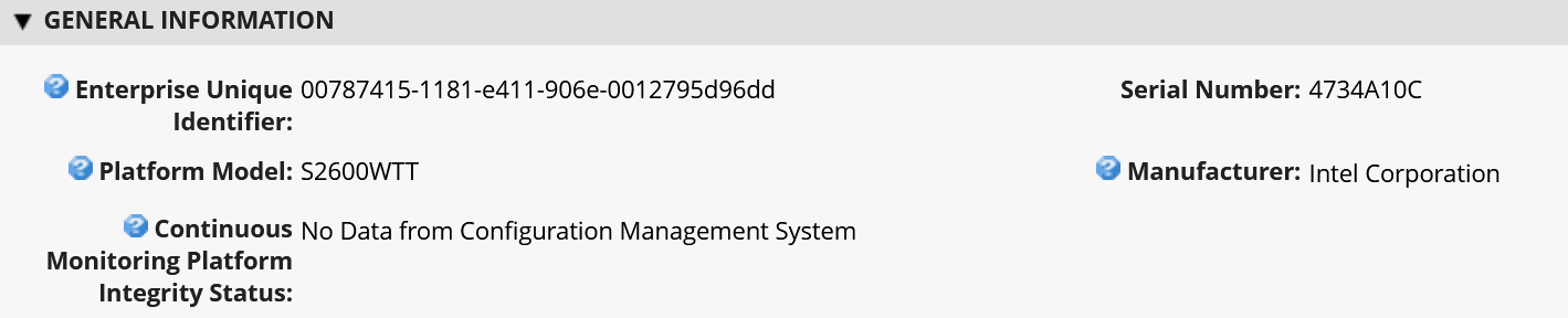
Figure 5‑5 below shows a partial listing of the components associated with the server in Figure 5‑4. Note that in this case, the three demonstration Seagate drives (Section 4.4.5) are also associated with the platform.
Figure 5‑5 Asset Inventory and Discovery Example 2

Once the Archer’s JavaScript DataFeed that retrieves data from the Eclypsium Analytic Backend (cloud or on-premises) executes, the asset record is updated accordingly with system firmware data, as Figure 5‑6 shows.
Figure 5‑6 Asset Inventory and Discovery Example 3
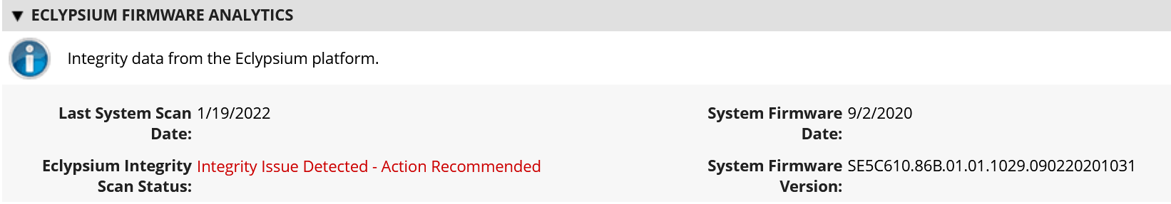
Step 4b:If the administrator updates the configuration of the platform (e.g., adding hardware components, updating firmware), then the administrator might create new platform artifacts to establish a new baseline.
A common use case for IT organizations is the replacement of a component in a fielded computing device. For example, an end user may request additional memory or the replacement of a broken component. This will cause future platform validation errors because the fielded computing device manifest will be updated to reflect the changed components and will differ from the as-built manifest. Below, we discuss three examples of updating the configuration of the platform that were demonstrated during the project.
In the first phase of this project, for laptop systems that leveraged the HIRS ACA platform, the verifiable artifact (Platform Certificate) is re-generated and uploaded to the HIRS ACA backend, and the device is re-provisioned by the IT administrator. In the second phase, we utilized delta certificates, which are defined as part of the TCG Platform Certificate Profile Specification 1.1. The specification defines a “base” Platform Certificate (Section 5.2.1) and a “delta” which attests to specific changes made to the platform that are not reflected in the original Platform Certificate. Generally, the Delta Platform Certificate is issued by the organizational owner of the computing device, as opposed to the base Platform Certificate, which is issued by the manufacturer. Once the HIRS-ACA has been updated with a new Delta Platform Certificate, it is able to track changes to the platform, forming a “chain” of Delta Platform Certificates which reference the Base Platform Certificate.
For systems that use Intel’s TSC platform, the IT administrator uploads the new computing device configuration to the TSC Web Portal using Intel’s software tools. The Intel TSC platform subsequently regenerates the verifiable artifacts, and the IT administrator makes them available for download when the provisioning process is restarted. We were able to exercise this process successfully using Intel-contributed laptops.
Finally, Dell server manifests are updated in the field by manufacturer technicians using specialized tools. The tooling generates a new manifest for the server, which is delivered to Dell’s environment and re-signed by Dell’s high-assurance certificate issuing authority that previously signed the original verifiable artifact embedded from the factory.
5.2.3 Scenario 3
The desired outcome of Scenario 3 is to ensure computing device components are verified against the attributes and measurements declared by the manufacturer or purchasing organization during operational usage. This scenario is primarily enabled by the Configuration Management System (Section 4.2.3), Eclypsium Analytic Platform (Section 4.3.4), and manufacturer-specific integrity monitoring tools. Supplemental sequence diagrams are available in Appendix C.
To support build testing of Intel TSC platforms in this scenario, we implemented a negative test case to simulate a platform integrity issue, such as a component swap. The scenario used the DPD intended for another system in place of the correct DPD to ensure the Intel platform validation would fail. We repeated this test with an incorrect Platform Certificate, which also failed validation as expected. The failed validation was subsequently detected by the configuration management system, which monitored the validation status of the Intel TSC tools as described in Section 4.2.3.
Similarly, we performed build testing of laptops that were continuously monitored by the HIRS-ACA Windows agent. In this test case we used a virtual machine to perform initial acceptance testing with the network-booted TPM Provisioner. The Windows-based TPM Provisioner was subsequently installed and monitored by the Configuration Management System. We then updated the virtual hardware to produce an integrity error (component swap) which was detected by the Configuration Management System.
HP Inc. supplied additional integrity event continuous monitoring scenarios and remediations that were demonstrated in our lab environment. In the first, we simulated an attempt by a locally present user to gain access to the firmware configuration user interface, and the system was rebooted to block a brute force attack. This event may be an indication of a malicious, locally present actor attempting to modify firmware settings. In the second demonstration, we simulated an event that indicated there was a repeated programmatic attempt made to modify a firmware (BIOS) setting without the proper authorization and that interface has been disabled until the next reboot. A reboot is required to re-enable the WMI interfaces that can be used to modify BIOS setting with proper authorization. This event may be an indication of malicious software present on the target device attempting to modify firmware settings. The two previous events may cause an action by the IT administrator, such as removing access to network enterprise resources. Finally, we ran a scenario in which the physical cover was removed from the laptop. This is indicative of potential physical tampering by an unauthorized party and the laptop is disabled. The remediation in this case is for the IT administrator to unlock the laptop.
The final use case we examined across all manufacturers is when system firmware is updated on the fielded laptop. This may be initiated by the end user who is guided by a helpdesk or by the IT administrator. In either case, the Eclypsium scanner that is installed during Scenario 2 detects this change and reflects it in the Eclypsium Analytic Backend. The Archer JavaScript Transporter Data Feed subsequently ingests the change, and it is reflected in the asset repository. Similarly, the Eclypsium Analytic Backend will detect out-of-date firmware versions and other potential platform integrity issues from laptops and servers that are monitored by the Eclypsium Analytic Platform. The demonstration observed this behavior through the normal lifecycle of manufacturer-provided firmware updates that include modifications to address vulnerabilities and active threats.
Similarly, firmware measurements produced by the Seagate Firmware Attestation capability are tracked for changes, and those changes are associated with the Intel server that the drives are connected to in this demonstration. A firmware measurement change in this case could be indicative of a non-malicious act, such as a firmware update. However, it could also represent an attack on the drive firmware that requires a recovery mechanism by the Security Operator.
With the platform and monitoring data collected from Scenario 3, we created a dashboard that enables an organization to achieve better visibility into supply chain attacks and detect advanced persistent threats and other advanced attacks. Depending on the size of the organization, the targeted audience may all be the same person. In the Validating the Integrity of Computing Devices project description of an IT administrator, it is possible that for some organizations, one person performs all those functions. In other organizations, functions might be addressed by separate teams within a SOC.
5.2.3.1 Continuous Monitoring Example
A snippet of the demonstration enterprise dashboard is provided in Figure 5‑7. There are two security event panels shown, which enable the IT administrator to quickly identify enterprise computing devices that are out of compliance and may require a remediation action. Enterprise Computing Devices with Out of Compliance Platform Manifests refers to the number of inventoried computing devices that have failed a compliance rule in the Configuration Management System. Enterprise Computing Devices with Out of Compliance Platform Integrity refers to the number of inventoried computing devices that the Eclypsium Analytic Platform (either on-premises or cloud) has identified as having an integrity issue. When either panel is clicked, a list of computing devices is presented, and the systems security engineer can make a risk management decision on the individual computing device.
Figure 5‑7 Scenario 3 Dashboard
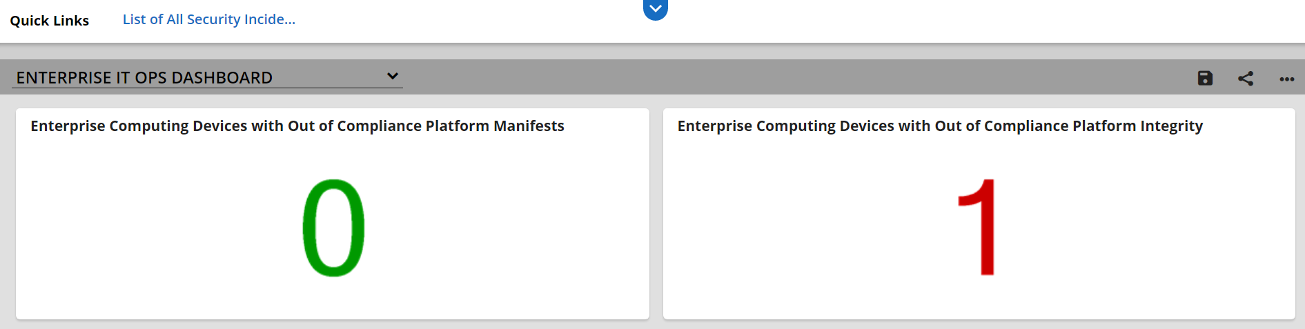
In addition to the dashboard described above, we demonstrated the capability to automatically create an incident tracking record when our SIEM detects a platform integrity security event for a SOC’s incident response team. The record is associated with the computing device as shown in Figure 5‑8. In this example incident, Archer has imported a security event (offense) from the SIEM involving a continuously monitored HP Inc. laptop.
Figure 5‑8 Scenario 3 Security Event
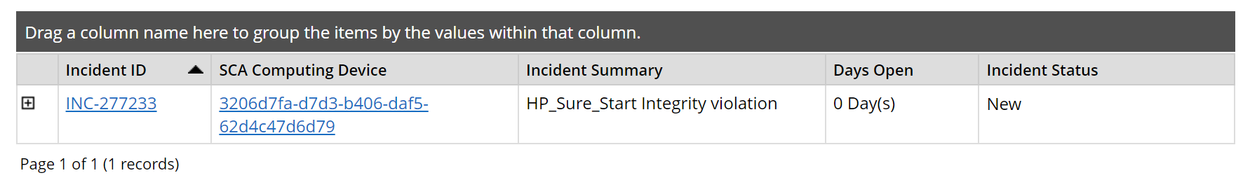
Clicking on the Incident ID reveals more details about the incident for the personnel assigned to investigate the incident for additional context. This is pictured in Figure 5‑9.
Figure 5‑9 Scenario 3 Security Event Summary
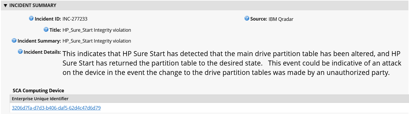
Finally, the Incident summary can provide a set of remediation actions for the security personnel. In the example (Figure 5‑10), an analyst has recommended that the incident response personnel remove the computing device in question from the environment. Other remediation actions related to platform integrity security events could include replacing a system component, updating or changing the firmware configuration, or executing manufacturer-specific platform recovery capabilities that are aligned with NIST SP 800-193, Platform Firmware Resiliency Guidelines.
Figure 5‑10 Scenario 3 Security Event Remediation
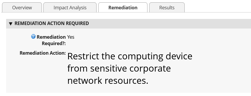
5.3 Scenarios and Findings
One aspect of our security evaluation involved assessing how well the reference design addresses the security characteristics that it was intended to support. The Cybersecurity Framework Subcategories were used to provide structure to the security assessment by consulting the specific sections of each standard that are cited in reference to a Subcategory. The cited sections provide validation points that the example solution would be expected to exhibit. Using the Cybersecurity Framework Subcategories as a basis for organizing our analysis allowed us to systematically consider how well the reference design supports the intended security characteristics. Refer to NIST’s Cybersecurity Framework website for category descriptions.
5.3.1 Supply Chain Risk Management (ID.SC)
5.3.1.1 ID.SC-4: Suppliers and third-party partners are routinely assessed using audits, test results, or other forms of evaluations, to confirm they are meeting their contractual obligations.
This Cybersecurity Framework Subcategory is supported in the prototype implementation by the manufacturer-specific validation tools and the HIRS ACA platforms. Specifically, Scenario 2 acceptance testing acts as an initial evaluation of the manufacturer (supplier) to validate the source and integrity of assembled components for the recipient organization of the computing device.
5.3.2 Asset Management (ID.AM)
5.3.2.1 ID.AM-1: Physical devices and systems within the organization are inventoried
This Cybersecurity Framework Subcategory is supported in the prototype implementation by Archer and the Platform Manifest Correlation System. When used in conjunction, they form the basis of an Asset Discovery and Management System that accurately reflects computing devices within an organization, including all components therein.
5.3.3 Identity Management, Authentication and Access Control (PR.AC)
5.3.3.1 PR.AC-6: Identities are proofed and bound to credentials and asserted in interactions
This Cybersecurity Framework Subcategory is supported in the prototype implementation by Archer and all hardware contributors. The manufacturers in this prototype support device-unique identifiers which are associated with organizational computing devices. Identifiers are prevented from being re-used through Archer data integrity (primary key) constraints.
5.3.4 Data Security (PR.DS)
5.3.4.1 PR.DS-6: Integrity-checking mechanisms are used to verify software, firmware, and information integrity
This Cybersecurity Framework Subcategory is supported in the prototype implementation by Archer and the Eclypsium Analytic Platform. Together, they provide the capability to detect unauthorized changes to firmware. All participating manufacturers provide capabilities to report firmware version information.
5.3.4.2 PR.DS-8: Integrity-checking mechanisms are used to verify hardware integrity
This Cybersecurity Framework Subcategory is supported in the prototype implementation by Archer, Microsoft Configuration Manager, IBM QRadar, and manufacturer-specific integrity validation tools. Together, these products provide the capability to document, manage, and control the integrity of changes to organizational computing devices.
5.3.5 Security Continuous Monitoring (DE.CM)
5.3.5.1 DE.CM-7: Monitoring for unauthorized personnel, connections, devices, and software is performed
This Cybersecurity Framework Subcategory is supported in the prototype implementation by Archer, Microsoft Configuration Manager, IBM QRadar, and the Eclypsium Analytic Platform. Together, these products form part of an organizational continuous monitoring program. Microsoft Endpoint Configuration Manager, IBM QRadar, and the Eclypsium platform enable automated monitoring of computing devices for hardware and firmware integrity issues at an organization-defined frequency. This security information is made available to organizational officials through an Archer dashboard, where a risk management decision can be made when a computing device is deemed out of compliance.
6 Future Build Considerations
In this publication, we have described an architecture that decreases the risk of a compromise to products in an organization’s supply chain, which in turn may reduce risks to customers and end users that use computing devices operationally. The second phase of this project built on the demonstration prototype from the first phase and incorporated servers into the architecture, to include hardware contributed by Dell, Hewlett Packard Enterprise, Intel, and Seagate. Additionally, we extended the architecture to include a SIEM contributed by IBM to support continuous monitoring scenarios. As we’ve demonstrated in this project, the TPM module provides a basis for a laptop or server’s root of trust. Newer specifications, such as the TCG’s Device Identifier Composition Engine (DICE) implementation, which currently addresses IoT devices, can be extended to platform components where a hardware root of trust is not feasible. Further, the Security Protocol and Data Model (SPDM) will provide the ability to securely communicate with the platform components, providing a similar mechanism that exists today with the Platform Certificates.
Similarly, TCG’s Reference Integrity Manifest (RIM) specification could extend our acceptance testing capability to provide firmware validation. This capability is dependent on manufacturer support in the form of a digitally signed “bundle” as a reference to the as-shipped firmware measurements.
Further, the concepts we have demonstrated in this project and described in this section could be integrated into a zero trust architecture. NIST SP 800-207, Zero Trust Architecture addresses this capability as part of a continuous diagnostics and mitigation (CDM) system. A CDM system is a core component of a zero trust architecture, which, among other functions, can detect the presence of non-approved components.
In closing, the NCCoE Supply Chain Assurance project team will continue to monitor the development of best practices and standards from industry and organizations such as the Trusted Computing Group that address platform integrity. We invite comments and suggestions from the C-SCRM community of interest that will enable organizations to operationalize the prototype demonstrations presented in this publication.