NIST SPECIAL PUBLICATION 1800-22C
Mobile Device Security:
Bring Your Own Device (BYOD)
Volume C:
How-to Guides
Kaitlin Boeckl
Nakia Grayson
Gema Howell
Naomi Lefkovitz
Applied Cybersecurity Division
Information Technology Laboratory
Jason Ajmo
R. Eugene Craft
Milissa McGinnis*
Kenneth Sandlin
Oksana Slivina
Julie Snyder
Paul Ward
The MITRE Corporation
McLean, VA
*Former employee; all work for this publication done while at employer
September 2023
FINAL
This publication is available free of charge from https://doi.org/10.6028/NIST.SP.1800-22

DISCLAIMER
Certain commercial entities, equipment, products, or materials may be identified by name or company logo or other insignia in order to acknowledge their participation in this collaboration or to describe an experimental procedure or concept adequately. Such identification is not intended to imply special status or relationship with NIST or recommendation or endorsement by NIST or NCCoE; neither is it intended to imply that the entities, equipment, products, or materials are necessarily the best available for the purpose.
National Institute of Standards and Technology Special Publication 1800-22C Natl. Inst. Stand. Technol. Spec. Publ. 1800-22C, 99 pages, (September 2023), CODEN: NSPUE2
FEEDBACK
As a private-public partnership, we are always seeking feedback on our practice guides. We are particularly interested in seeing how businesses apply NCCoE reference designs in the real world. If you have implemented the reference design, or have questions about applying it in your environment, please email us at mobile-nccoe@nist.gov.
All comments are subject to release under the Freedom of Information Act.
NATIONAL CYBERSECURITY CENTER OF EXCELLENCE
The National Cybersecurity Center of Excellence (NCCoE), a part of the National Institute of Standards and Technology (NIST), is a collaborative hub where industry organizations, government agencies, and academic institutions work together to address businesses’ most pressing cybersecurity issues. This public-private partnership enables the creation of practical cybersecurity solutions for specific industries, as well as for broad, cross-sector technology challenges. Through consortia under Cooperative Research and Development Agreements (CRADAs), including technology partners—from Fortune 50 market leaders to smaller companies specializing in information technology security—the NCCoE applies standards and best practices to develop modular, easily adaptable example cybersecurity solutions using commercially available technology. The NCCoE documents these example solutions in the NIST Special Publication 1800 series, which maps capabilities to the NIST Cyber Security Framework and details the steps needed for another entity to recreate the example solution. The NCCoE was established in 2012 by NIST in partnership with the State of Maryland and Montgomery County, Maryland.
NIST CYBERSECURITY PRACTICE GUIDES
NIST Cybersecurity Practice Guides (Special Publication Series 1800) target specific cybersecurity challenges in the public and private sectors. They are practical, user-friendly guides that facilitate the adoption of standards-based approaches to cybersecurity. They show members of the information security community how to implement example solutions that help them align with relevant standards and best practices, and provide users with the materials lists, configuration files, and other information they need to implement a similar approach.
The documents in this series describe example implementations of cybersecurity practices that businesses and other organizations may voluntarily adopt. These documents do not describe regulations or mandatory practices, nor do they carry statutory authority.
This Practice Guide demonstrates a standards-based reference design and provides users with the information they need to replicate enhancing the security of bring your own device (BYOD) solutions. This reference design is modular and can be deployed in whole or in part.
This guide contains four volumes:
NIST SP 1800-22A: Executive Summary
NIST SP 1800-22B: Approach, Architecture, and Security Characteristics – what we built and why
NIST SP 1800-22 Supplement: Example Scenario: Putting Guidance into Practice – how organizations can implement this example solution’s guidance
NIST SP 1800-22C: How-To Guides – instructions for building the example solution
ABSTRACT
Bring Your Own Device (BYOD) refers to the practice of performing work-related activities on personally owned devices. This practice guide provides an example solution demonstrating how to enhance security and privacy in Android and Apple phones and tablets used in BYOD deployments.
Incorporating BYOD deployments into an organization can increase the opportunities and methods available to access organizational resources. For some organizations, the combination of traditional in-office processes with mobile device technologies enables portable communication approaches and adaptive workflows. For others, it fosters a mobile-first approach in which their employees communicate and collaborate primarily using their mobile devices.
However, some of the features that make BYOD mobile devices increasingly flexible and functional also present unique security and privacy challenges to both organizations and device owners. The unique nature of these challenges is driven by the differing risks posed by the type, age, operating system (OS), and other variances in mobile devices.
Enabling BYOD capabilities in the enterprise introduces new cybersecurity risks. Solutions that are designed to secure corporate devices and on-premises data do not provide an effective cybersecurity solution for BYOD. Finding an effective solution can be challenging due to the unique risks that BYOD deployments impose. Additionally, enabling BYOD capabilities introduces new privacy risks to employees by providing their employer a degree of access to their personal devices, opening up the possibility of observation and control that would not otherwise exist.
To help organizations benefit from BYOD’s flexibility while protecting themselves from critical security and privacy challenges, this practice guide provides an example solution using standards-based, commercially available products and step-by-step implementation guidance.
KEYWORDS
Bring your own device; BYOD; mobile device management; mobile device security.
ACKNOWLEDGMENTS
We are grateful to the following individuals for their generous contributions of expertise and time.
Name |
Organization |
|---|---|
Donna Dodson* |
NIST |
Joshua M. Franklin* |
NIST |
Dylan Gilbert |
NIST |
Jeff Greene* |
NIST |
Natalia Martin |
NIST |
William Newhouse |
NIST |
Cherilyn Pascoe |
NIST |
Murugiah Souppaya |
NIST |
Kevin Stine |
NIST |
Chris Brown |
The MITRE Corporation |
Nancy Correll* |
The MITRE Corporation |
Spike E. Dog |
The MITRE Corporation |
Sallie Edwards |
The MITRE Corporation |
Parisa Grayeli |
The MITRE Corporation |
Marisa Harriston* |
The MITRE Corporation |
Brian Johnson* |
The MITRE Corporation |
Karri Meldorf |
The MITRE Corporation |
Steven Sharma* |
The MITRE Corporation |
Jessica Walton |
The MITRE Corporation |
Erin Wheeler* |
The MITRE Corporation |
Dr. Behnam Shariati |
University of Maryland, Baltimore County |
Jeffrey Ward* |
IBM |
Cesare Coscia* |
IBM |
Chris Gogoel |
Kryptowire (now known as Quokka) |
Tom Karygiannis* |
Kryptowire (now known as Quokka) |
Jeff Lamoureaux |
Palo Alto Networks |
Sean Morgan |
Palo Alto Networks |
Kabir Kasargod |
Qualcomm |
Viji Raveendran |
Qualcomm |
Mikel Draghici* |
Zimperium |
*Former employee; all work for this publication done while at employer.
The Technology Partners/Collaborators who participated in this build submitted their capabilities in response to a notice in the Federal Register. Respondents with relevant capabilities or product components were invited to sign a Cooperative Research and Development Agreement (CRADA) with NIST, allowing them to participate in a consortium to build this example solution. We worked with:
Technology Partner/Collaborator |
Build Involvement |
|---|---|
IBM |
Mobile Device Management |
Kryptowire (now known as Quokka) |
Application Vetting |
Palo Alto Networks |
Firewall; Virtual Private Network |
Qualcomm |
Trusted Execution Environment |
Zimperium |
Mobile Threat Defense |
DOCUMENT CONVENTIONS
The terms “shall” and “shall not” indicate requirements to be followed strictly to conform to the publication and from which no deviation is permitted. The terms “should” and “should not” indicate that among several possibilities, one is recommended as particularly suitable without mentioning or excluding others, or that a certain course of action is preferred but not necessarily required, or that (in the negative form) a certain possibility or course of action is discouraged but not prohibited. The terms “may” and “need not” indicate a course of action permissible within the limits of the publication. The terms “can” and “cannot” indicate a possibility and capability, whether material, physical, or causal.
PATENT DISCLOSURE NOTICE
NOTICE: The Information Technology Laboratory (ITL) has requested that holders of patent claims whose use may be required for compliance with the guidance or requirements of this publication disclose such patent claims to ITL. However, holders of patents are not obligated to respond to ITL calls for patents and ITL has not undertaken a patent search in order to identify which, if any, patents may apply to this publication.
As of the date of publication and following call(s) for the identification of patent claims whose use may be required for compliance with the guidance or requirements of this publication, no such patent claims have been identified to ITL.
No representation is made or implied by ITL that licenses are not required to avoid patent infringement in the use of this publication.
List of Figures
Figure 1‑1 High-Level Build Architecture
Figure 2‑1 Post-Deployment Configuration
Figure 2‑2 PasswordMax Registry Configuration
Figure 2‑3 NDES Domain Bindings
Figure 2‑4 Cloud Extender Architecture
Figure 2‑5 Old Cloud Extender Interface
Figure 2‑6 Cloud Extender Service Account Details
Figure 2‑7 Administrator Settings
Figure 2‑8 Administrator Configuration Options
Figure 2‑9 Cloud Extender SCEP Configuration
Figure 2‑10 Cloud Extender Certificate Properties
Figure 2‑11 Enterprise Binding Settings Confirmation
Figure 2‑12 Where to Click to Download the Public Key
Figure 2‑13 MDM configuration in Apple Business Manager
Figure 2‑14 Creating the DEP token
Figure 2‑15 VPP token in MaaS360
Figure 2‑16 iOS Enrollment Configuration
Figure 2‑17 Android GlobalProtect Application Compliance
Figure 2‑18 Zimperium MaaS360 Integration Configuration
Figure 2‑19 Zimperium zIPS iOS Configuration
Figure 2‑20 Zimperium zIPS Android Configuration
Figure 2‑22 Zimperium Risk Posture Alert Configuration
Figure 2‑23 DNS Proxy Object Configuration
Figure 2‑24 Original Packet Network Address Translation Configuration
Figure 2‑25 Certificate Profile
Figure 2‑26 Custom URL Category
Figure 2‑27 URL Filtering Profile
Figure 2‑28 URL Filtering Security Policy
Figure 2‑29 Generating the Root CA
Figure 2‑30 Blocked Website Notification
Figure 2‑31 Service Route Configuration
Figure 2‑32 LDAP Server Profile
Figure 2‑33 LDAP Group Mapping
Figure 2‑34 LDAP User Authentication Profile
Figure 2‑35 Configured Tunnel Interfaces
Figure 2‑36 SSL VPN Tunnel Interface Configuration
Figure 2‑37 GlobalProtect iOS Authentication Profile
Figure 2‑38 LDAP Authentication Group Configuration
Figure 2‑39 VPN Zone Configuration
Figure 2‑40 GlobalProtect Portal General Configuration
Figure 2‑41 GlobalProtect Portal Authentication Configuration
Figure 2‑42 GlobalProtect Portal Agent Authentication Configuration
Figure 2‑43 GlobalProtect Portal Agent Configuration
Figure 2‑44 Captive Portal Configuration
Figure 2‑45 GlobalProtect Portal
Figure 2‑46 Downloaded Threats and Applications
Figure 2‑47 Schedule Time Hyperlink
Figure 2‑48 Application and Threats Update Schedule
Figure D‑1 Contact Created in Work Profile
Figure D‑2 Personal Profile Can’t See Work Contacts
Figure D‑3 Contact Created in Managed App
Figure D‑4 Unmanaged App Can’t See Managed Contacts
Figure D‑5 Fictitious Phishing Webpage Blocked
Figure D‑6 iOS MaaS360 OS Compliance Alert
Figure D‑7 Zimperium Risk Detected
Figure D‑8 Kryptowire Application Report
Figure D‑9 Android Passcode Configuration
Figure D‑10 iOS Passcode Configuration
Figure D‑11 Zimperium Detecting Disabled Lock screen
Figure D‑12 Application Report with Hardcoded Credentials
Figure D‑13 Attempting to Access the VPN on an Unmanaged iOS Device
Figure D‑14 Attempting to Access the VPN on an Unmanaged Android Device
Figure D‑15 Attempting to Access the VPN on a Managed Android Device
Figure D‑16 Selective Wiping a Device
Figure D‑17 Selective Wipe Complete
Figure D‑18 Corporate Data Removal Confirmation Notification on iOS
Figure D‑19 Work Profile Removal Notification on Android
Figure D‑20 iOS DLP Configuration Options
Figure D‑21 Android DLP Configuration
Figure D‑22 Attempting to Paste Text on iOS Between Unmanaged and Managed Apps
Figure D‑24 Application Inventory Information
Figure D‑25 Location Information Restricted
Figure D‑26 Non-Administrator Failed Portal Login
Figure D‑27 Admin Login Settings
Figure D‑28 Administrator Levels
Figure D‑29 Mobile Device Information Collection Notification
Figure D‑30 Mobile Device Information Collection Notification
Figure D‑31 Privacy and Information Access of the Application
Figure D‑32 Application Analysis
1 Introduction
The following volumes of this guide show information technology (IT) professionals and security engineers how we implemented this example solution. We cover all of the products employed in this reference design. We do not re-create the product manufacturers’ documentation, which is presumed to be widely available. Rather, these volumes show how we incorporated the products together in our environment.
Note: These are not comprehensive tutorials. There are many possible service and security configurations for these products that are out of scope for this reference design.
1.1 Practice Guide Structure
This National Institute of Standards and Technology (NIST) Cybersecurity Practice Guide demonstrates a standards-based reference design and provides users with the information they need to replicate enhancing the security of bring your own device (BYOD) solutions. This reference design is modular and can be deployed in whole or in part.
This guide contains four volumes:
NIST SP 1800-22B: Approach, Architecture, and Security Characteristics – what we built and why
NIST SP 1800-22 Supplement: Example Scenario: Putting Guidance into Practice – how organizations can implement this example solution’s guidance
NIST SP 1800-22C: How-To Guides – instructions for building the example solution (you are here)
Depending on your role in your organization, you might use this guide in different ways:
Business decision makers, including chief security and technology officers, will be interested in the Executive Summary, NIST SP 1800-22A*, which describes the following topics:
challenges that enterprises face in managing the security of BYOD deployments
the example solution built at the NCCoE
benefits of adopting the example solution
Technology or security program managers who are concerned with how to identify, understand, assess, and mitigate risk will be interested in NIST SP 1800-22B, which describes what we did and why. The following sections will be of particular interest:
Section 3.4, Conduct a Risk Assessment, describes the risk analysis we performed.
Appendix E in Volume B, Example Security Subcategory and Control Map, maps the security characteristics of this example solution to cybersecurity standards and best practices.
You might share the Executive Summary, NIST SP 1800-22A, with your leadership team members to help them understand the importance of adopting standards-based BYOD solutions.
IT professionals who want to implement an approach like this will find this whole practice guide useful. You can use this How-To portion of the guide, NIST SP 1800-22C, to replicate all or parts of the build created in our lab. This How-To portion of the guide provides specific product installation, configuration, and integration instructions for implementing the example solution. We do not recreate the product manufacturers’ documentation, which is generally widely available. Rather, we show how we incorporated the products together in our environment to create an example solution.
This guide assumes that IT professionals have experience implementing security products within the enterprise. While we have used a suite of commercial products to address this challenge, this guide does not endorse these particular products. Your organization can adopt this solution or one that adheres to these guidelines in whole, or you can use this guide as a starting point for tailoring and implementing parts of a BYOD solution. Your organization’s security experts should identify the products that will best integrate with your existing tools and IT system infrastructure. We hope that you will seek products that are congruent with applicable standards and best practices. Volume B, Section 4.3, Technologies that Support the Security and Privacy Objectives of the Example Solution, lists the products that we used and maps them to the cybersecurity controls provided by this reference solution.
For those who would like to see how the example solution can be implemented, this practice guide contains an example scenario about a fictional company called Great Seneca Accounting. The example scenario shows how BYOD objectives can align with an organization’s priority security and privacy capabilities through NIST risk management standards, guidance, and tools. It is provided in this practice guide’s supplement, NIST SP 1800-22 Example Scenario: Putting Guidance into Practice.
A NIST Cybersecurity Practice Guide does not describe “the” solution, but a possible solution. This is a draft guide. We seek feedback on its contents and welcome your input. Comments, suggestions, and success stories will improve subsequent versions of this guide. Please contribute your thoughts to mobile-nccoe@nist.gov.
1.2 Build Overview
In our lab at the National Cybersecurity Center of Excellence (NCCoE), NIST engineers built an environment that contains an example solution for managing the security of BYOD deployments. In this guide, we show how an enterprise can leverage this example solution’s concepts to implement Enterprise Mobility Management (EMM), mobile threat defense, application vetting, secure boot/image authentication, and virtual private network (VPN) services in support of a BYOD solution.
These technologies were configured to protect organizational assets and end-user privacy, providing methodologies to enhance the data protection posture of the adopting organization. The standards, best practices, and certification programs that this example solution is based upon help ensure the confidentiality, integrity, and availability of enterprise data on mobile systems.
1.3 Typographic Conventions
The following table presents typographic conventions used in this volume.
Typeface/Symbol |
Meaning |
Example |
|---|---|---|
Italics |
file names and path names; references to documents that are not hyperlinks; new terms; and placeholders |
For language use and style guidance, see the NCCoE Style Guide. |
Bold |
names of menus, options, command buttons, and fields |
Choose File > Edit. |
Monospace |
command-line input, onscreen computer output, sample code examples, and status codes |
mkdir |
Monospace Bold |
command-line user input contrasted with computer output |
service sshd start |
blue text |
link to other parts of the document, a web URL, or an email address |
All publications from NIST’s NCCoE are available at https://www.nccoe.nist.gov. |
Acronyms can be found in Appendix A.
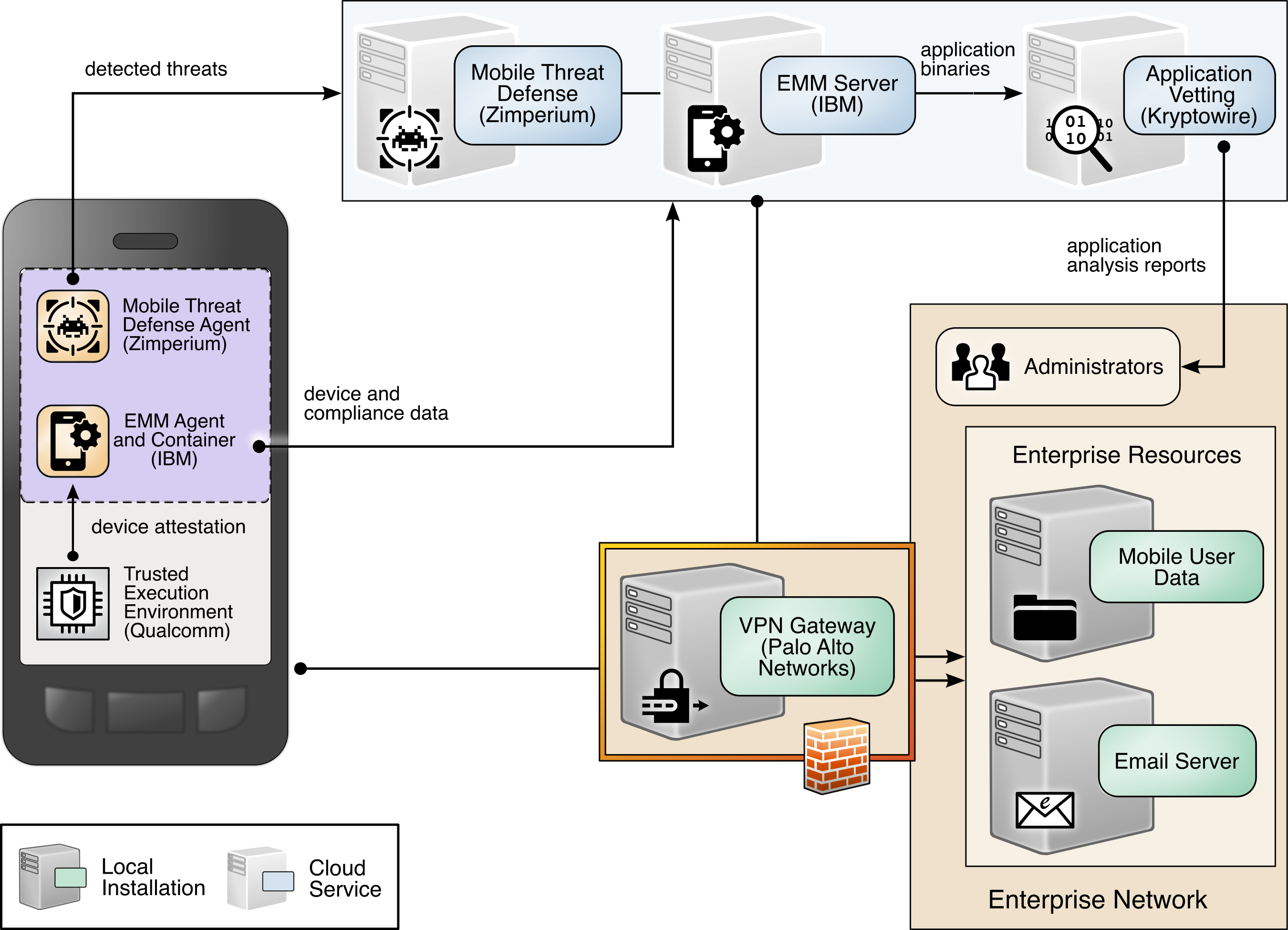
1.4 Logical Architecture Summary
Figure 1-1 shows the components of the build architecture and how they interact on a high level.
Figure 1‑1 High-Level Build Architecture
2 Product Installation Guides
This section of the practice guide contains detailed instructions for installing and configuring all the products used to build an instance of the example solution.
This guide assumes that a basic active directory (AD) infrastructure has been configured. The domain controller (DC) is used to authenticate users when enrolling devices as well as when connecting to the virtual private network (VPN). In this implementation, the domain enterprise.mds.local was used.
2.1 Network Device Enrollment Services Server
A Network Device Enrollment Service (NDES)/Simple Certificate Enrollment Protocol (SCEP) server was used to issue client certificates to new devices that were enrolled by using MaaS360. This guide assumes that a basic AD and certificate authority (CA) are in place, containing a root and subordinate CA, and that their certificates have been exported.
2.1.1 NDES Configuration
This section outlines configuration of an NDES that resides on its own server. Alternatively, the NDES can be installed on the SUB-CA. This section assumes a new domain-attached Windows Server is running.
From the Server Manager, select Manage > Add Roles and Features.
Click Next three times until Server Roles is highlighted.
Check the box next to Active Directory Certificate Services.
Click Next three times until Role Services is highlighted.
Uncheck Certification Authority. Check Network Device Enrollment Service.
Click Add Features on the pop-up.
Click Next three times.
Click Install.
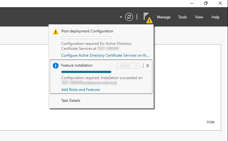
When the installation completes, click the flag in the upper right-hand corner, and click Configure Active Directory Certificate Services.
Figure 2‑1 Post-Deployment Configuration
Specify the credentials of a Domain Administrator. Click Next.
Note: The domain administrator credentials are required only to configure the NDES. Once the service is configured, the service is executed as the NDES service account, which does not require domain administrator permissions, created in step 12 below.
Check Network Device Enrollment Service. Click Next.
Configure an NDES service account by performing the following actions:
On the active directory server, open Active Directory Users and Computers.
Click Users and create a new user for the service. For this example, it will be named NDES. Be sure the password never expires.
On the NDES server, open Edit local users and groups.
Click Groups. Right-click IIS_IUSRS, click Add to Group, and click Add.
Search for the service account name—in this case, NDES. Click Check Names, then click OK if no errors were displayed.
Click Apply and click OK.
Close all windows except the NDES configuration window.
Click Select next to the box and enter the service account credentials. Click Next.
Because the NDES runs on its own server, we will target it at the SUB-CA. Select Computer name and click Select. Type in the computer name—in this case, SUB-CA. Click Check Names, and if no errors occurred, click OK.
Click Next three times.
Click Configure.
On the SUB-CA, open the Certification Authority application.
Expand the SUB-CA node, right-click on Certificate Templates, and click Manage.
Right-click on IPSec (Offline Request) and click Duplicate Template.
Under the General tab, set the template display name to NDES.
Under the Security tab, click Add.
Select the previously configured NDES service account.
Click OK. Ensure the NDES service account is highlighted, and check Read and Enroll.
Click Apply.
In the Certification Authority program, right-click on Certificate Templates, and select New > Certificate Template to Issue.
Select the NDES template created in step 24.
Click OK.
On the NDES server, open the Registry Editor (
regedit).Expand the following key:
HKLM\SOFTWARE\Microsoft\Cryptography.Select the MSCEP key and update all entries besides (Default) to be NDES.
Expand the following key:
HKLM\SOFTWARE\Microsoft\Cryptography\MSCEP.Right-click on MSCEP and select New > Key. Name it PasswordMax.
Right-click on the newly created key and select New > DWORD (32-bit) Value.
Name it PasswordMax and give it a value of 0x00003e8. This increases the NDES password cache to 1,000 entries instead of the default 5. This value can be further adjusted based on NDES demands.
Figure 2‑2 PasswordMax Registry Configuration
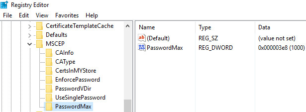
Note: The PasswordMax key governs the maximum number of NDES passwords that can reside in the cache. A password is cached when a valid certificate request is received, and it is removed from the cache when the password is used or when 60 minutes have elapsed, whichever occurs first. If the PasswordMax key is not present, the default value of 5 is used.
In an elevated command prompt, execute
%windir%\system32\inetsrv\appcmd set config /section:requestFiltering /requestLimits.maxQueryString:8192to increase the maximum query string. This prevents requests longer than 2,048 bytes from being dropped.Open the Internet Information Services (IIS) Manager.
On the left, expand NDES > Sites, and select Default Web Site.
On the right, click Bindings…
Click Add.
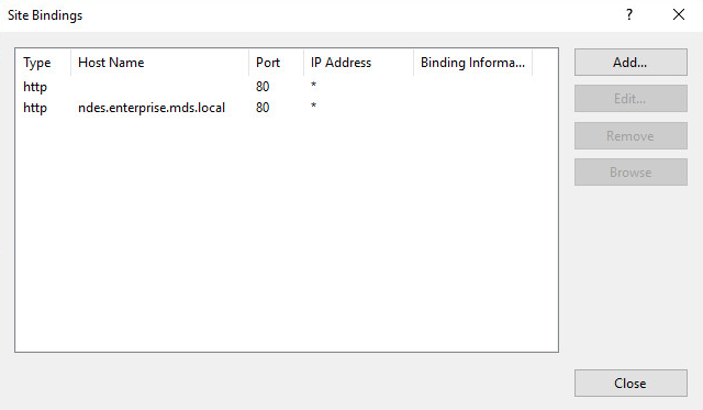
Below Host Name, enter the host name of the server. For this implementation, ndes.enterprise.mds.local was used.
Click OK.
Figure 2‑3 NDES Domain Bindings
Click Close and close the IIS Manager.
In an elevated command prompt, execute
iisreset, or reboot the NDES server.
2.2 International Business Machines MaaS360
International Business Machines (IBM) contributed an instance of MaaS360 to deploy as the mobile device management (MDM) solution.
2.2.1 Cloud Extender
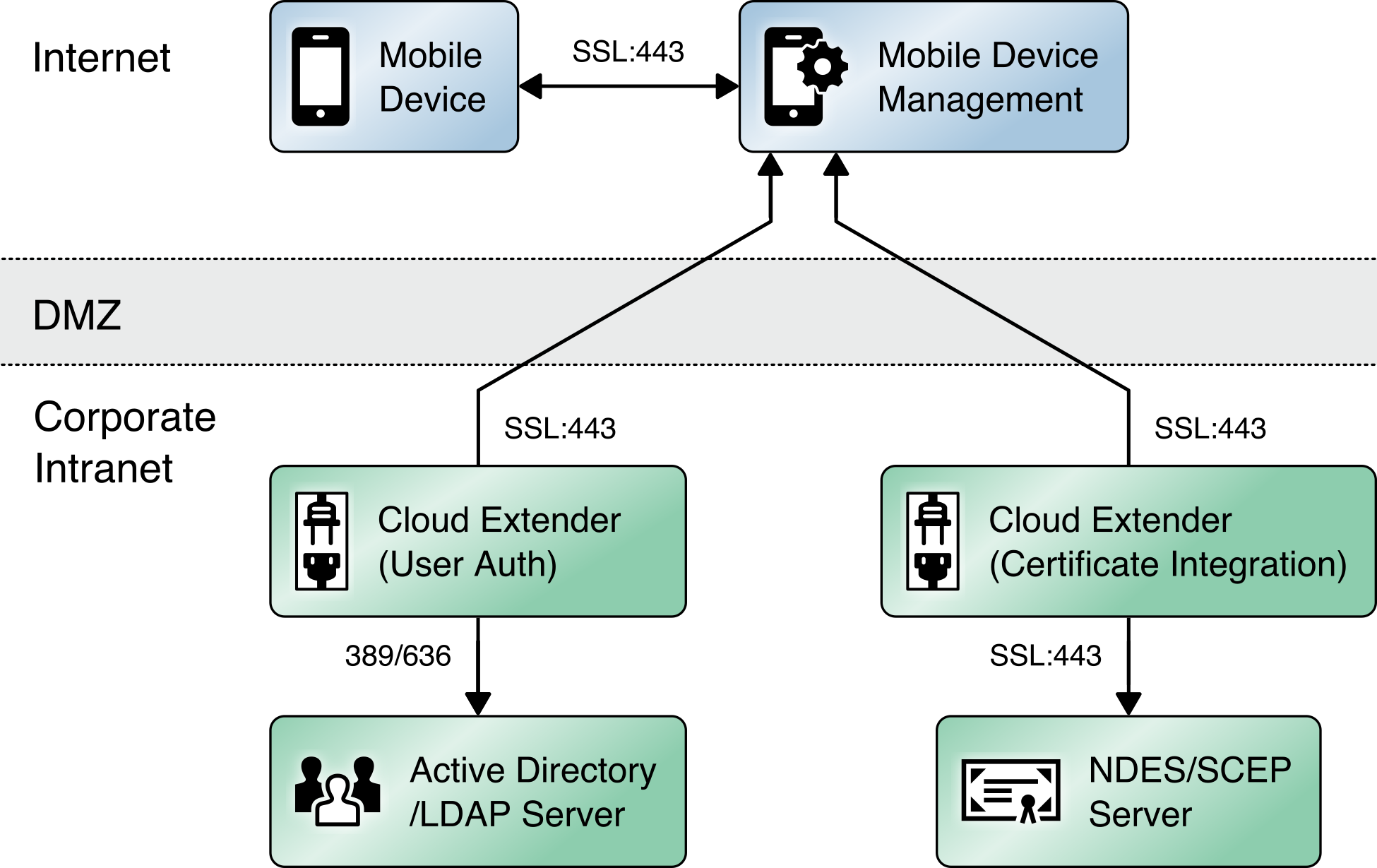
The IBM MaaS360 Cloud Extender is installed within the AD domain to provide AD and lightweight directory access protocol (LDAP) authentication methods for the MaaS360 web portal, as well as corporate VPN capabilities. The cloud extender architecture [C1], as shown in Figure 2‑4, gives a visual overview of how information flows between the web portal and the MaaS360 Cloud Extender.
Figure 2‑4 Cloud Extender Architecture
2.2.1.1 Cloud Extender Download
Log in to the MaaS360 web portal.
Click Setup > Cloud Extender.
Click the link that says Click here to get your License Key. The license key will be emailed to the currently logged-in user’s email address.
Click the link that says Click here to download the Cloud Extender. Save the binary.
Move the binary to a machine behind the corporate firewall that is always online. Recommendation: Install it while logged in as a domain user on a machine that is not the domain controller.
Install .NET 3.5 Features in the Server Manager on the machine where the MaaS360 Cloud Extender will run.
2.2.1.2 Cloud Extender Active Directory Configuration
On the target machine, run the installation binary.
Enter the license key when prompted.
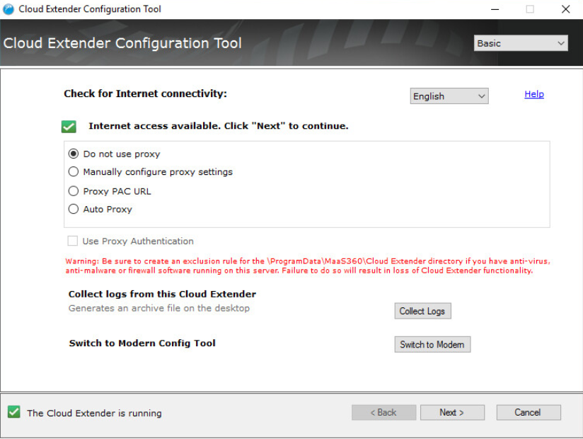
Proceed through the setup until the Cloud Extender Configuration Utility opens.
If using the old cloud extender interface, click Switch to Modern.
Figure 2‑5 Old Cloud Extender Interface
Enable the toggle below User Authentication.
Create a new authentication profile by entering the username, password, and domain of the created service account.
Figure 2‑6 Cloud Extender Service Account Details
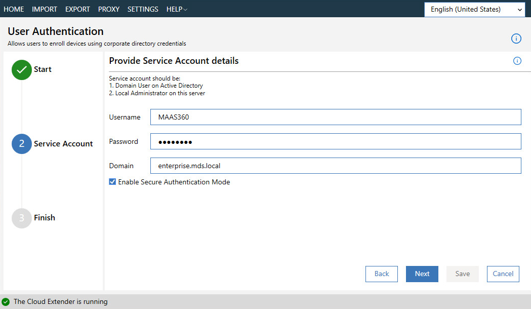
Click Next.
(optional) Use the next page to test the active directory integration.
Click Save.
In MaaS360, navigate to Setup > Cloud Extender. Ensure that configuration information is displayed, indicating that the MaaS360 Cloud Extender is running.
2.2.1.3 MaaS360 Portal Active Directory Authentication Configuration
Log in to the MaaS360 web portal as an administrator.
Go to Setup > Settings.
Expand Administrator Settings and click Advanced.
Figure 2‑7 Administrator Settings
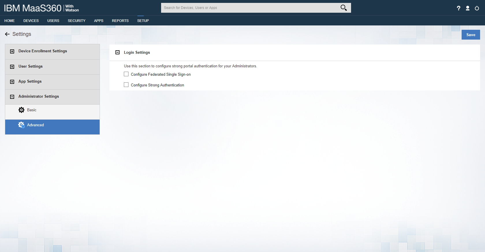
Select Configure Federated Single Sign-on.
Select Authenticate against Corporate User Directory.
Next to Default Domain, enter the active directory domain. In this implementation, enterprise.mds.local was used.
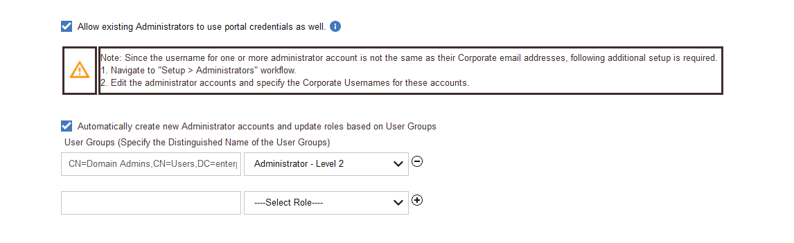
Check the box next to Allow existing Administrators to use portal credentials as well.
Check the box next to Automatically create new Administrator accounts and update roles based on user groups.
Under User Groups, enter the distinguished name of the group(s) that should be allowed to log in. In this implementation, CN=Domain Admins, CN=Users, DC=enterprise, DC=mds, DC=local was used.
Next to the box, select Administrator–Level 2. This allows domain admins to log in as MaaS360 administrators.
Figure 2‑8 Administrator Configuration Options
Click Save.
2.2.1.4 Cloud Extender NDES Integration
To properly generate device certificates, MaaS360 must be integrated with the on-premises public key infrastructure (PKI).
Log in to the server running the MaaS360 Cloud Extender.
Launch the Cloud Extender Configuration Tool.
Toggle the button below Certificate Integration.
Click Add New Template.
Ensure Microsoft CA and Device Identity Certificates are selected.
Click Next.
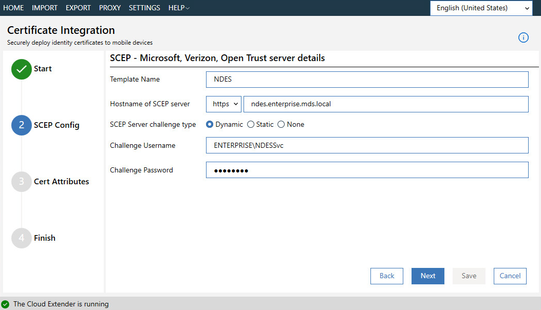
Enter NDES for the Template Name and SCEP Default Template.
Enter the uniform resource locator (URL) of the NDES server next to SCEP Server.
Enter credentials of a user with enroll permissions on the template for Challenge Username and Challenge Password. For this demo implementation, we use the NDES service account.
Figure 2‑9 Cloud Extender SCEP Configuration
Click Next.
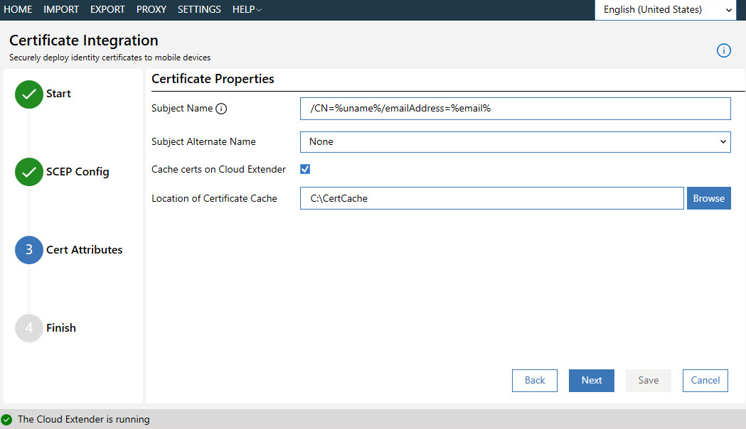
(optional) Check the box next to Cache certs on Cloud Extender and specify a cache path on the machine.
Figure 2‑10 Cloud Extender Certificate Properties
Click Next.
(optional) Enter values for uname and email and generate a test certificate to test the configuration.
Click Save.
Note: If a file access message appears, delete the file, and re-save the file.
2.2.2 Android Enterprise Configuration
A Google account was used to provision Android Enterprise on the mobile devices. A managed domain can be used, but in this use case it was not necessary. A managed domain is necessary only if the corporation already has data stored in Google’s cloud.
Create a Google account if you do not have one you wish to bind with.
From the MaaS360 portal, navigate to Setup > Services.
Click Mobile Device Management.
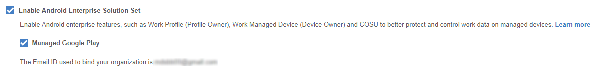
Check the box next to Enable Android Enterprise Solution Set.
Enter your password and click Enable.
Click Mobile Device Management.
Click the radio button next to Enable via Managed Google Play Accounts (no G Suite).
Ensure all pop-up blockers are disabled. Click the link on the word here.
Enter your password and click Enable.
In the new page that opens, ensure you are signed into the Google account you wish to bind.
Click Get started.
Enter your business name and click Next.
If General Data Protection Regulation compliance is not required, scroll to the bottom, check the I agree box, and click Confirm. If compliance is required, fill out the requested information first.
Click Complete Registration.
Confirm binding on the Setup page under Mobile Device Management. The settings should look like Figure 2‑11, where the blurred-out portion is the Google email address used to bind.
Figure 2‑11 Enterprise Binding Settings Confirmation
2.2.3 iOS APNs Certificate Configuration
For the iOS Apple Push Notification services (APNs) certificate configuration, the build team followed the IBM documentation.
2.2.4 Apple User Enrollment (UE) Configuration
The following sections detail the configuration process for Apple User Enrollment, which enables BYOD on iOS devices.
2.2.4.1 Apple Business Manager (ABM) Configuration
In MaaS360, navigate to Setup > Settings > Enrollment Programs, and click Configure next to Apple Device Enrollment Program.
In the popup, click Continue.
Click Tokens > Add Token.
In the popup, give the token a name and click on the here link in step 2 of the popup to download the public key file.
Figure 2‑12 Where to Click to Download the Public Key

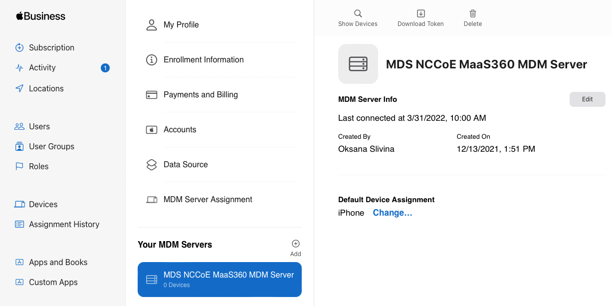
In Apple Business Manager, sign in with an administrator account.
Click the user’s name in the bottom left corner > Settings.
Click Add next to “Your MDM Servers” and enter a unique name for the server.
Upload the public key certificate file downloaded in step (4), then click Save.
Click Download Token to save the server token.
Figure 2‑13 MDM configuration in Apple Business Manager
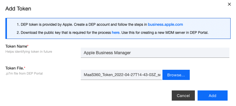
In MaaS360, click Browse and select the token downloaded in step (9).
Click Add.
Figure 2‑14 Creating the DEP token
In Apple Business Manager, click the user’s name in the bottom left corner and click Payments and Billing.
Under Server Tokens, click the token that corresponds to the Apple Business Manager tenant and save the token.
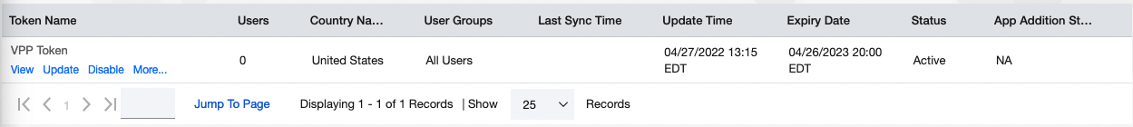
In MaaS360, navigate to Apps > Catalogue. Click More > Apple VPP Licenses.
Click Add Token and give the token a name. Click Browse and select the token file downloaded in step (13).
Click Policies and configure the VPP token policy based on organizational requirements.
Click Distribution and configure based on organizational requirements.
Click Submit.
Figure 2‑15 VPP token in MaaS360
2.2.4.2 MaaS360 Configuration
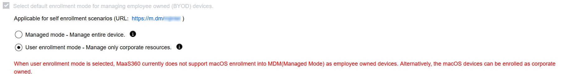
In the MaaS360 web portal, navigate to Setup > Settings.
Navigate to Device Enrollment Settings > Advanced.
Under Advanced Management for Apple Devices > Select default enrollment mode for managing employee owned (BYOD) devices, select the radio button next to User enrollment mode.
Scroll to the top of the page and click Save.
Figure 2‑16 iOS Enrollment Configuration
2.2.5 Android Configuration
The following sections detail the configuration policies applied to enrolled Android devices.
2.2.5.1 Policy Configuration
Navigate to Security > Policies.
Click the appropriate deployed Android policy.
Click Edit.
Navigate to Android Enterprise Settings > Passcode.
Check the box next to Configure Passcode Policy.
Configure the passcode settings based on corporate requirements.
Navigate to Android Enterprise Settings > Restrictions.
Check the box next to Configure Restrictions.
Configure restrictions based on corporate requirements.
Click Save.
2.2.5.2 VPN Configuration
Navigate to Security > Policies.
Click the currently deployed Android device policy.
Click Edit.
Navigate to Android Enterprise Settings > Certificates.
Check the box next to Configure CA Certificates.
Click Add New.
Give the certificate a name, such as Internal Root.
Click Browse and navigate to the exported root CA certificate from earlier in the document.
Click Save.
Select Internal Root from the drop-down next to CA Certificate.
Click the + icon on the far right.
Repeat steps 6–10 with the internal sub-CA certificate.
Check the box next to Configure Identity Certificates.
From the drop-down next to Identity Certificate, select the profile that matches the name configured on the MaaS360 Cloud Extender—for this example, NDES.
Click Save and Publish and follow the prompts to publish the updated policy. Click Apps.
Click Add > Android > Google Play App.
Select the radio button next to Add via Public Google Play Store.
Search for GlobalProtect.
Select the matching result.
Click I Agree when prompted to accept the permissions.
Check the three boxes next to Remove App on.
Check the box next to Instant Install.
Select All Devices next to Distribute to.
Click Add.
Next to the newly added GlobalProtect application, select More > Edit App Configurations.
Click Check for Settings.
Next to Portal, enter the GlobalProtect portal address. In this implementation, vpn.ent.mdse.nccoe.org was used.
Next to Username, enter %username%.
Next to Connection Method, enter user-logon. (Note: This will enable an always-on VPN connection for the work profile. The user will always see the VPN key icon, but it will apply only to applications contained within the work profile.)
Click Save and follow the prompts to update the application configuration.
Navigate to Security > Policies.
Click the used Android policy.
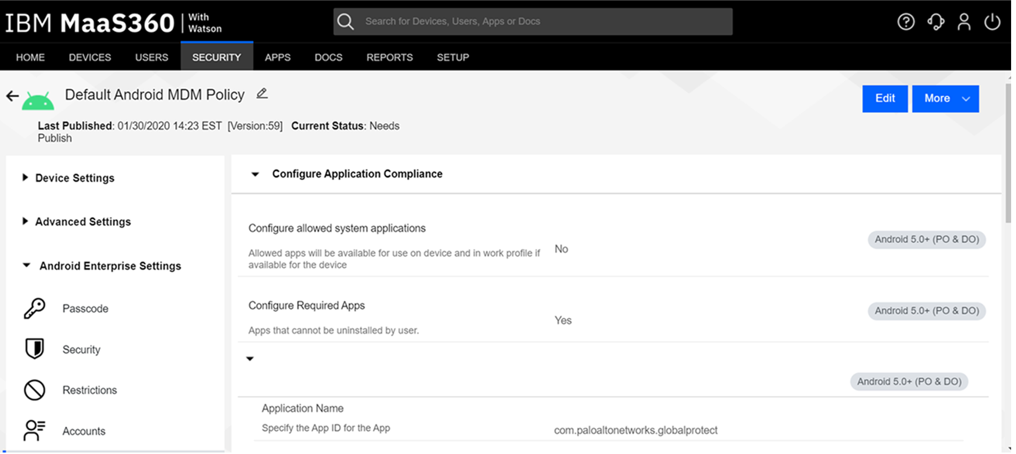
Select Android Enterprise Settings > App Compliance.
Click Edit.
Click the + on the row below Configure Required Apps.
Enter the App Name, GlobalProtect.
Enter the App ID, com.paloaltonetworks.globalprotect.
Click Save And Publish and follow the prompts to publish the policy.
Figure 2‑17 Android GlobalProtect Application Compliance
2.2.6 iOS Configuration
The following sections detail the configuration policies applied to enrolled iOS devices.
2.2.6.1 Policy Configuration
Navigate to Security > Policies.
Click the deployed iOS policy.
Click Edit.
Check the box next to Configure Passcode Policy.
Check the box next to Enforce Passcode on Mobile Device.
Configure the rest of the displayed options based on corporate requirements.
Click Restrictions.
Check the box next to Configure Device Restrictions.
Configure restrictions based on corporate requirements.
Click Save.
2.2.6.2 VPN Configuration
Click Device Settings > VPN.
Click Edit.
Next to Configure for Type, select Custom SSL.
Enter a name next to VPN Connection Name. In this sample implementation, Great Seneca VPN was used.
Next to Identifier, enter com.paloaltonetworks.globalprotect.vpn.
Next to Host name of the VPN Server, enter the URL of the VPN endpoint without http or https.
Next to VPN User Account, enter %username%.
Next to User Authentication Type, select Certificate.
Next to Identity Certificate, select the name of the certificate profile created during the NDES configuration steps. In this sample implementation, NDES was used.
Next to Custom Data 1, enter allowPortalProfile=0.
Next to Custom Data 2, enter fromAspen=1.
Next to Apps to use this VPN, enter the application identifications (IDs) of applications to go through the VPN. This will be the applications deployed to the devices as work applications.
Next to Provider Type, select Packet Tunnel.
In Apple Business Manager, click Apps and Books.
Search for GlobalProtect.
Select the non-legacy search result.
Select the business’s location and enter the desired number of licenses (installations) and click Get.
In MaaS360, navigate to Apps > Catalog.
Navigate to More > Apple VPP Licenses.
In the VPP line, select More > Sync. Follow the confirmation pop-ups to confirm the sync with Apple Business Manager.
Navigate to Apps > Catalog.
Click Add > iOS > iTunes App Store App.
Search for GlobalProtect.
Select the non-Legacy version.
Click Policies and Distribution.
Check all three boxes next to Remove App on.
Select All Devices next to Distribute to.
Check the box next to Instant Install.
Click Add.
Navigate to Security > Policies.
Click the used iOS policy.
Click Application Compliance.
Click Edit.
Click the + next to the first row under Configure Required Applications.
Search for GlobalProtect.
Select the non-Legacy result.
Navigate to Advanced Settings > Certificate Credentials.
Check the box next to Configure Credentials for Adding Certificates on the Device.
Click Add New.
Give the certificate a name, such as Internal Root.
Click Browse and navigate to the exported root CA certificate from earlier in the document.
Click Save.
Select Internal Root from the drop-down next to CA Certificate.
Click the + icon on the far right.
Repeat steps 33–35 with the internal sub-CA certificate.
From the drop-down next to Identity Certificate, select the profile that matches the name configured on the MaaS360 Cloud Extender—for this example, NDES.
Click Save And Publish and follow the prompts to publish the policy.
2.3 Zimperium
Zimperium was used as a mobile threat defense service via a MaaS360 integration.
Note: For Zimperium automatic enrollment to function properly, users must have an email address associated with their MaaS360 user account.
2.3.1 Zimperium and MaaS360 Integration
This section assumes that IBM has provisioned an application programming interface (API) key for Zimperium within MaaS360.
Log in to the zConsole.
Navigate to Manage > MDM.
Select Add MDM > MaaS360.
Fill out the MDM URL, MDM username, MDM password, and API key.
Note: For the MDM URL, append the account ID to the end. For example, if the account ID is 12345, the MDM URL would be https://services.fiberlink.com/12345.
Check the box next to Sync users.
Figure 2‑18 Zimperium MaaS360 Integration Configuration

Click Next.
Select the MaaS360 groups to synchronize with Zimperium. In this case, All Devices was selected.
Click Finish. Click Sync Now to synchronize all current MaaS360 users and devices.
2.3.2 Automatic Device Activation
Note: This requires contacting Zimperium support to get required application configuration values.
In Apple Business Manager, click Apps and Books.
Search for Zimperium zIPS.
Select the non-legacy search result.
Select the business’s location and enter the desired number of licenses (installations) and click Get.
In MaaS360, navigate to Apps > Catalog.
Navigate to More > Apple VPP Licenses.
In the VPP line, select More > Sync. Follow the confirmation pop-ups to confirm the sync with Apple Business Manager.
Click Apps on the navigation bar.
Click Add > iOS > iTunes App Store App.
Search for Zimperium zIPS. Click the result that matches the name.
Click Policies and Distribution.
Check the three checkboxes next to Remove App on.
Next to Distribute to, select All Devices.
Click Configuration.
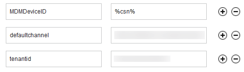
Set App Config Source to Key/Value.
The configuration requires three parameters: uuid, defaultchannel, and tenantid. uuid can be set to %csn%, but defaultchannel and tenantid must come from Zimperium support.
Figure 2‑19 Zimperium zIPS iOS Configuration
Click Add.
Click Add > Android > Google Play App.
Select the radio button next to Add via Public Google Play Store.
Search for Zimperium Mobile IPS (zIPS).
Click the matching result.
Click I Agree when prompted to accept permissions.
Click Policies and Distribution.
Check all three boxes next to Remove App on.
Check Instant Install.
Select All Devices next to Distribute to.
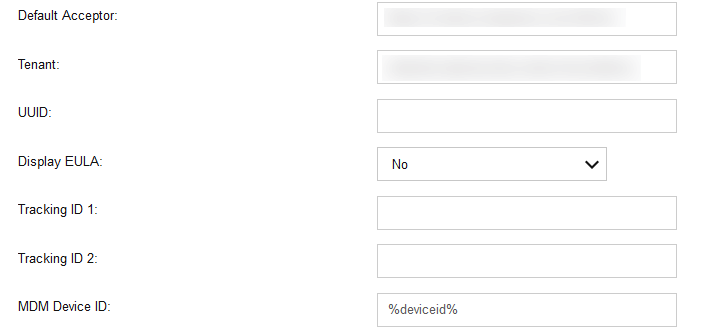
Click App Configurations.
Check Configure App Settings.
Enter the values provided by Zimperium next to Default Acceptor and Tenant.
Next to MDM Device ID, insert %deviceid%.
Adjust any other configuration parameters as appropriate for your deployment scenario.
Figure 2‑20 Zimperium zIPS Android Configuration
Click Add.
2.3.3 Enforce Application Compliance
From the IBM MaaS360 web portal:
Navigate to Security > Policies.
Select the default Android policy.
Navigate to Android Enterprise Settings > App Compliance.
Click Edit.
Check the box next to Configure Required Apps if not checked already. If it is, click the + icon.
Enter com.zimperium.zips as the App ID.
Click Save And Publish. This will prevent the user from uninstalling zIPS once it is installed.
Navigate to Security > Policies.
Select the default iOS policy.
Click Application Compliance.
Click Edit.
Check the box next to Configure Required Applications if not checked already. If it is, click the + icon.
Enter Zimperium zIPS for the Application Name.
Click Save And Publish and follow the prompts to publish the policy.
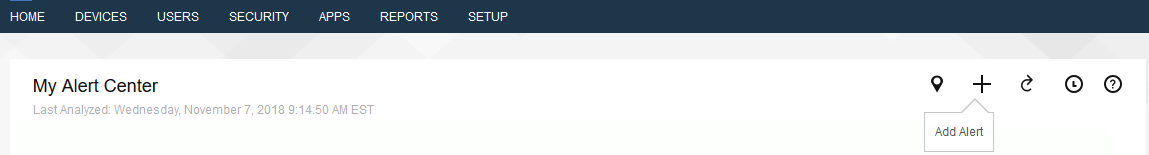
2.3.4 MaaS360 Risk Posture Alerts
From the MaaS360 home screen, click the + button that says Add Alert.
Figure 2‑21 Add Alert Button
Next to Available for select All Administrators.
For Name, enter Zimperium Risk Posture Elevated.
Under Condition 1, select Custom Attributes for the Category.
Select zimperium_risk_posture for Attribute.
Select Equal To for Criteria.
For Value, select Elevated for the count of risk posture elevated devices or Critical for risk posture critical devices.
Figure 2‑22 Zimperium Risk Posture Alert Configuration
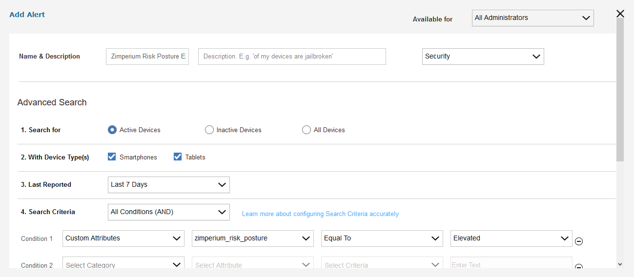
Click Update.
2.4 Palo Alto Networks Virtual Firewall
Palo Alto Networks contributed an instance of its VM-100 series firewall for use on the project.
2.4.1 Network Configuration
Ensure that all Ethernet cables are connected or assigned to the virtual machine and that the management web user interface is accessible. Setup will require four Ethernet connections: one for management, one for wide area network (WAN), one for local area network, and one for the demilitarized zone (DMZ).
Reboot the machine if cables were attached while running.
Navigate to Network > Interfaces > Ethernet.
Click ethernet1/1 and set the Interface Type to be Layer3.
Click IPv4, ensure that Static is selected under Type, and click Add to add a new static address.
If the appropriate address does not exist yet, click New Address at the bottom of the prompt.
Once the appropriate interfaces are configured, commit the changes. The Link State icon should turn green for the configured interfaces. The commit dialogue will warn about unconfigured zones. That is an expected dialogue warning.
Navigate to Network > Zones.
Click Add. Give the zone an appropriate name, set the Type to Layer3, and assign it an interface.
Commit the changes.
Navigate to Network > Virtual Routers.
Click Add.
Give the router an appropriate name and add the internal and external interfaces.
Click Static Routes > Add. Give the static route an appropriate name, e.g., WAN. Set the destination to be 0.0.0.0/0, set the interface to be the WAN interface, and set the next hop internet protocol (IP) address to be the upstream gateway’s IP address.
(optional) Delete the default router by clicking the checkbox next to it and clicking Delete at the bottom of the page.
Commit the changes. The commit window should not display any more warnings.
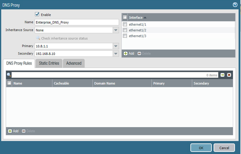
Navigate to Network > DNS Proxy.
Click Add.
Give the proxy an appropriate name. Under Primary, enter the primary domain name system (DNS) IP address.
(optional) Enter the secondary DNS IP address.
Add the interfaces under Interface. Click OK.
Figure 2‑23 DNS Proxy Object Configuration
Navigate to Device > Services.
Click the gear in the top-right corner of the Services panel.
Under DNS settings, click the radio button next to DNS Proxy Object. Select the created DNS proxy object from the drop-down.
Click OK and commit the changes. This is where static DNS entries will be added in the future.
Navigate to Objects > Addresses.
For each device on the network, click Add. Give the device an appropriate name, enter an optional description, and enter the IP address.
Click OK.
Once all devices are added, commit the changes.
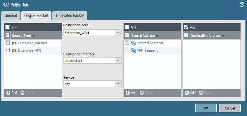
Navigate to Policies > NAT.
Click Add.
Give the network address translation rule a meaningful name, such as External Internet Access.
Click Original Packet.
Click Add and add the zone representing the intranet—in this case, Enterprise_Intranet.
Repeat step 34 for the secure sockets layer (SSL) VPN zone.
Under Source Address, click Add.
Enter the subnet corresponding to the intranet segment.
Repeat step 37 for the SSL VPN segment.
Click Translated Packet. Set the translation type to Dynamic IP and Port. Set Address Type to be Interface Address. Set Interface to be the WAN interface and set the IP address to be the WAN IP of the firewall.
Click OK and commit the changes.
Figure 2‑24 Original Packet Network Address Translation Configuration
2.4.2 Demilitarized Zone Configuration
Navigate to Network > Interfaces.
Click the interface that has the DMZ connection.
Add a comment, set the Interface Type to Layer3, and assign it to the virtual router created earlier.
Click IPv4 > Add > New Address. Assign it an IP block and give it a meaningful name. Click OK.
Navigate to Network > Zones.
Click Add. Give it a meaningful name, such as Enterprise_DMZ.
Set the Type to Layer3 and assign it the new interface that was configured—in this case, ethernet1/3.
Click OK.
Navigate to Network > DNS Proxy. Click Add under Interface and add the newly created interface. Click OK.
Commit the changes.
Navigate to Network > Interfaces, and the configured interfaces should be green.
2.4.3 Firewall Configuration
Navigate to Policies > Security.
Click Add.
Give the rule a meaningful name, such as Intranet Outbound.
Click Source. Click Add under Source Zone and set the source zone to be the internal network.
Click Destination. Click Add under Destination Zone and set the destination zone to be the WAN zone.
Click Service/URL Category. Under Service, click Add, and add service-dns. Do the same for service-http and service-https.
Click OK.
Click Add.
Click Destination. Add the IP address of the Simple Mail Transfer Protocol (SMTP) server.
Click Application. Click Add.
Search for smtp. Select it.
Click OK.
Commit the changes.
Internal hosts should now be able to communicate on the internet.
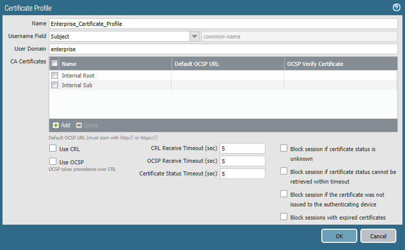
2.4.4 Certificate Configuration
Navigate to Device > Certificate Management > Certificate Profile.
Click Add.
Give the profile a meaningful name, such as Enterprise_Certificate_Profile.
Select Subject under Username Field.
Select the radio button next to Principal Name.
Enter the domain under User Domain—in this case, enterprise.
Click Add under CA Certificates. Select the internal root CA certificate.
Click Add under CA Certificates. Select the internal sub-CA certificate. (Note: The entire certificate chain must be included in the certificate profile.)
Click OK.
Commit the changes.
Figure 2‑25 Certificate Profile
2.4.5 Website Filtering Configuration
The following sections detail the configuration of website blocking on the Palo Alto firewall.
2.4.5.1 Configure Basic Website Blocking
Navigate to Objects > URL Category.
Click Add.
Enter a name for the URL Category. Click Add on the bottom.
Add websites that should be blocked. Use the form *.example.com for all subdomains and example.com for the root domain.
Figure 2‑26 Custom URL Category
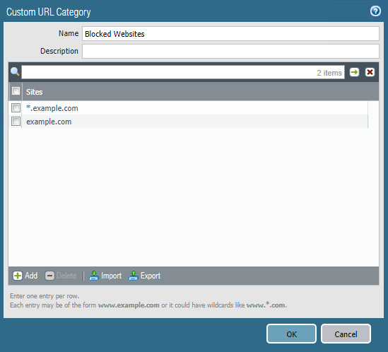
Click OK.
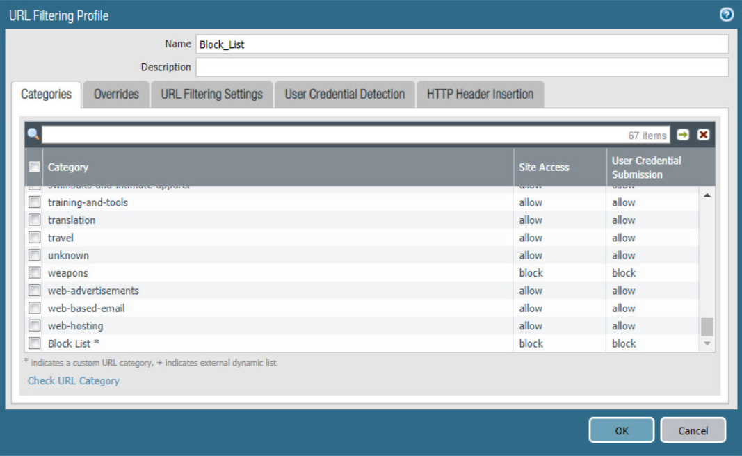
Navigate to Objects > URL Filtering.
Click Add.
Give the filtering profile a name.
Scroll to the bottom of the categories table. The profile created in step 4 should be the last item in the list, with an asterisk next to it. Click where it says allow and change the value to block.
Configure any additional categories to allow, alert, continue, block, or override.
Figure 2‑27 URL Filtering Profile
Click OK.
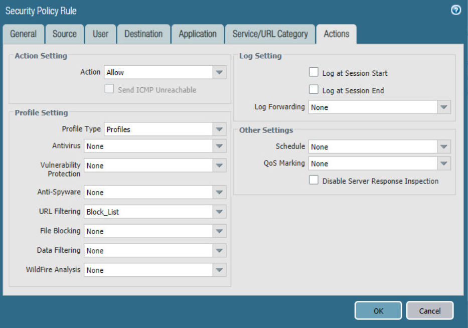
Navigate to Policies > Security.
Select a policy to apply the URL filtering to.
Select Actions.
Next to Profile Type, select Profiles.
Next to URL Filtering, select the created URL filtering profile.
Figure 2‑28 URL Filtering Security Policy
Click OK.
Repeat steps 13–17 for any policies that need the filtering profile applied.
Commit the changes.
2.4.5.2 Configure SSL Website Blocking
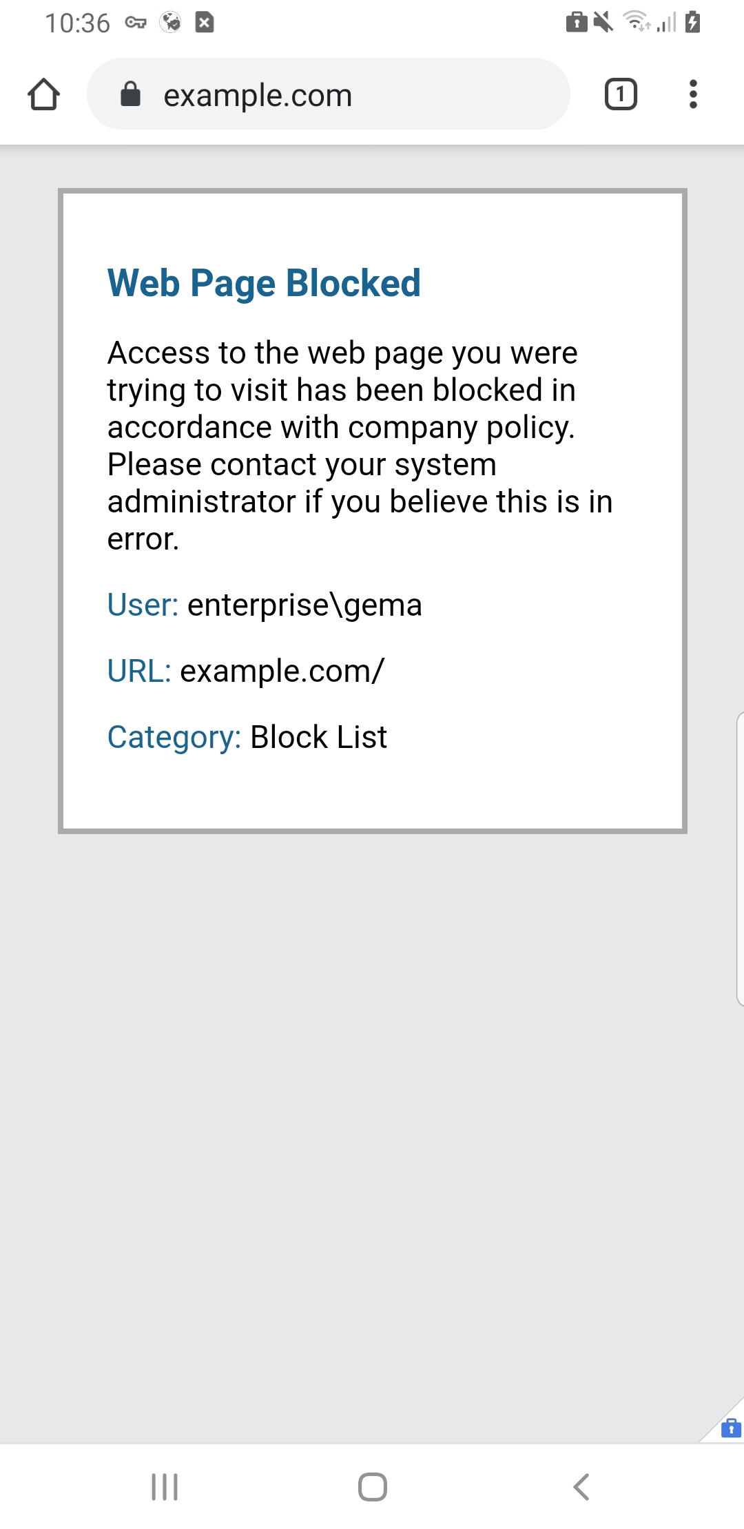
Note: This section is optional. Section 2.4.5.1 outlines how to configure basic URL filtering, which will serve a URL blocked page for unencrypted (http [hypertext transfer protocol]) connections, and it will send a transmission control protocol reset for encrypted (https [hypertext transfer protocol secure]) connections, which will show a default browser error page. This section outlines how to configure the firewall so that it can serve the same error page for https connections as it does for http connections. This is purely for user experience and has no impact on blocking functionality.
Navigate to Device > Certificates.
Click Generate on the bottom of the page.
Give the root certificate a name, such as SSL Decryption Root; and a common name (CN) such as PA Root.
Check the box next to Certificate Authority.
Figure 2‑29 Generating the Root CA
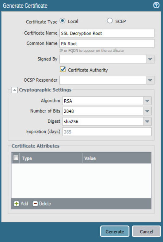
Click Generate.
Click Generate at the bottom of the page.
Give the certificate a name, such as SSL Decryption Intermediate.
Give the certificate a CN, such as PA Intermediate.
Next to Signed By, select the generated root CA. In this case, SSL Decryption Root was selected.
Check the box next to Certificate Authority.
Click Generate.
Click the newly created certificate.
Check the boxes next to Forward Trust Certificate and Forward Untrust Certificate.
Click OK.
Navigate to Policies > Decryption.
Click Add.
Give the policy a name and description.
Click Source.
Under Source Zone, click Add.
Select the source zone(s) that matches the security policy that uses URL filtering. In this implementation, the Intranet and SSL VPN zones were selected.
Click Destination.
Under Destination Zone, click Add.
Select the destination zone that matches the security policy that uses URL filtering. Most likely it is the WAN zone.
Click Service/URL Category.
Under URL Category, click Add.
Select the created block list. This ensures that only sites matching the block list are decrypted.
Click Options.
Next to Action, select Decrypt.
Next to Type, select SSL Forward Proxy.
Next to Decryption Profile, select None.
Click OK.
Commit the changes.
Figure 2‑30 Blocked Website Notification
2.4.6 User Authentication Configuration
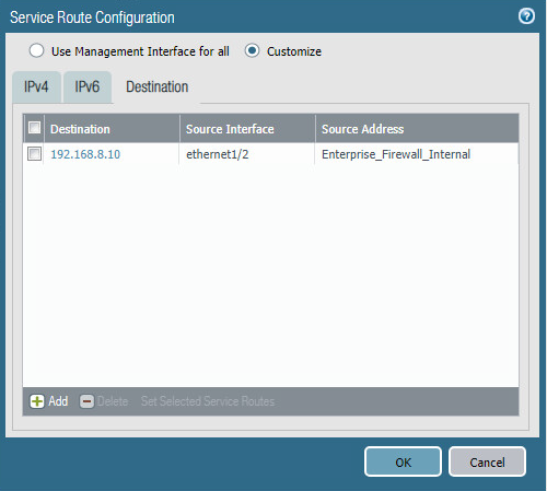
Navigate to Device > Setup > Services > Service Route Configuration.
Click Destination.
Click Add.
Enter the IP address of the internal LDAP server for Destination.
Select the internal network adapter for Source Interface.
Select the firewall’s internal IP address for Source Address.
Click OK twice and commit the changes.
Figure 2‑31 Service Route Configuration
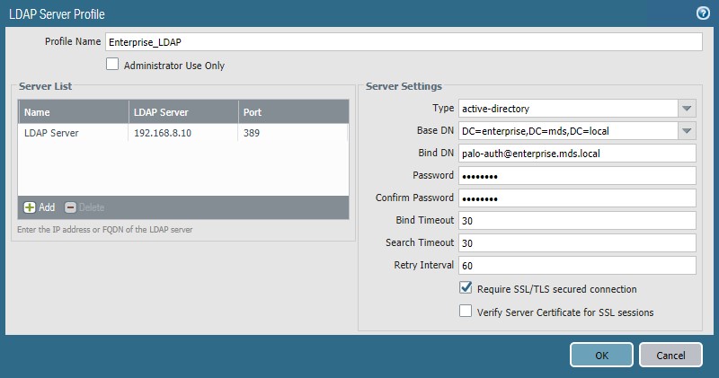
Navigate to Device > Server Profiles > LDAP.
Click Add.
Give the profile a meaningful name, such as Enterprise_LDAP_Server.
Click Add in the server list. Enter the name for the server and the IP.
Under Server Settings, set the Type drop-down to active-directory.
Enter the Bind DN and the password for the Bind DN.
Note: In this implementation, a new user, palo-auth, was created in Active Directory. This user does not require any special permissions or groups beyond the standard Domain Users group.
Ensure that Require SSL/TLS secured connection is checked.
Click the down arrow next to Base DN. If the connection is successful, the Base DN (Distinguished Name) should display.
Click OK.
Figure 2‑32 LDAP Server Profile
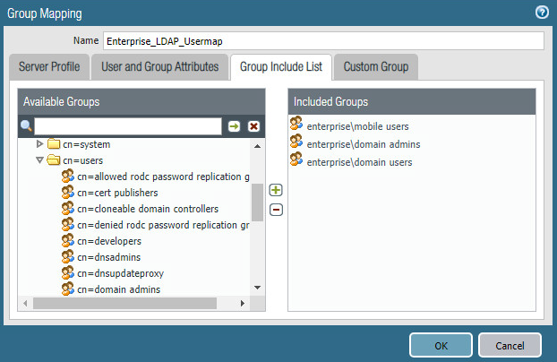
Navigate to Device > User Identification > Group Mapping Settings.
Click Add.
Give the mapping a name, such as Enterprise_LDAP_Usermap.
Select the server profile, and enter the user domain—in this case, Enterprise.
Click Group Include List.
Expand the arrow next to the base DN and then again next to cn=users.
For each group that should be allowed to connect to the VPN, click the proper entry and then the + button. In this example implementation, mobile users, domain users, and domain admins were used.
Figure 2‑33 LDAP Group Mapping
Click OK.
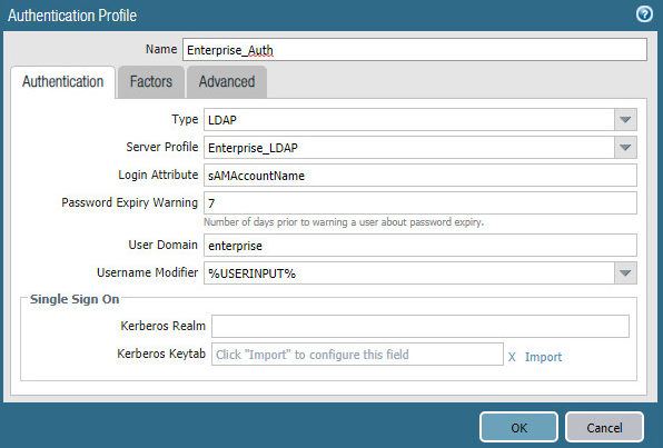
Navigate to Device > Authentication Profile.
Click Add.
Give the profile a meaningful name, such as Enterprise_Auth.
For the Type, select LDAP.
Select the newly created LDAP profile next to Server Profile.
Set the Login Attribute to be sAMAcountName.
Set the User Domain to be the LDAP domain name—in this case, enterprise.
Figure 2‑34 LDAP User Authentication Profile
Click on Advanced.
Click Add. Select enterprisedomain users.
Repeat step 33 for mobile users and domain admins.
Click OK.
Commit the changes.
2.4.7 VPN Configuration
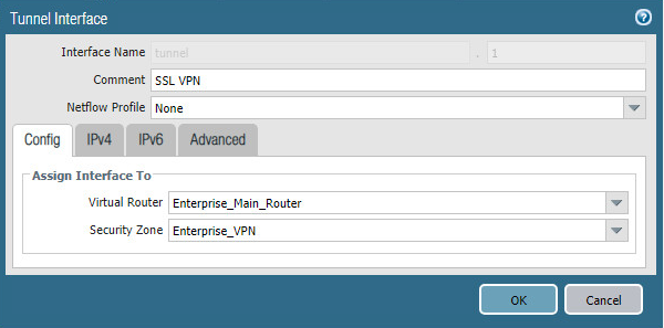
Navigate to Network > Interfaces > Tunnel.
Click Add.
Enter a tunnel number. Assign it to the main virtual router. Click OK.
Figure 2‑35 Configured Tunnel Interfaces

Click the newly created tunnel.
Click the drop-down next to Security Zone. Select New Zone.
Give it a name and assign it to the newly created tunnel. Click OK twice.
Figure 2‑36 SSL VPN Tunnel Interface Configuration
Commit the changes.
Navigate to Policies > Authentication.
Click Add.
Give the policy a descriptive name. For this example, the rule was named VPN_Auth.
Click Source.
Click Add and add the VPN and WAN zones.
Click Destination.
Check the Any box above Destination Zone.
Click Service/URL Category.
Click Add under Service and add service-https.
Click Actions.
Next to Authentication Enforcement, select default-web-form.
Click OK.
2.4.7.1 Configure the GlobalProtect Gateway
Navigate to Network > GlobalProtect > Gateways.
Click Add.
Give the gateway a meaningful name. For this implementation, the name Enterprise_VPN_Gateway was used.
Under Interface, select the WAN Ethernet interface.
Ensure that IPv4 Only is selected next to IP Address Type.
Select the WAN IP of the firewall next to IPv4 Address. Ensure that end clients can resolve it.
Click Authentication.
Select the created SSL/TLS service profile next to SSL/TLS Service Profile.
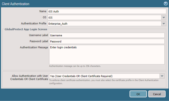
Click Add under Client Authentication.
Give the object a meaningful name, such as iOS Auth.
Next to OS, select iOS.
Next to Authentication Profile, select the created Authentication Profile.
Next to Allow Authentication with User Credentials OR Client Certificate, select Yes.
Figure 2‑37 GlobalProtect iOS Authentication Profile
Click OK.
Click Add under Client Authentication.
Give the object a meaningful name, such as Android Auth.
Next to OS, select Android.
Next to Authentication Profile, select the created Authentication Profile.
Next to Allow Authentication with User Credentials OR Client Certificate, select No.
Click Agent.
Check the box next to Tunnel Mode.
Select the created tunnel interface next to Tunnel Interface.
Uncheck Enable IPSec.
Click Timeout Settings.
Set Disconnect On Idle to an organization defined time.
Click Client IP Pool.
Click Add and assign an IP subnet to the clients—in this case, 10.3.3.0/24.
Click Client Settings.
Click Add.
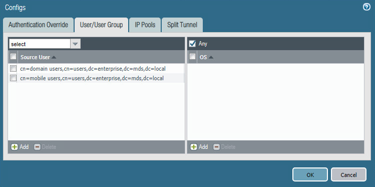
Give the config a meaningful name, such as Enterprise_Remote_Access.
Click User/User Group.
Click Add under Source User.
Enter the LDAP information of the group allowed to use this rule. In this example, implementation, domain users, and mobile users were used.
Figure 2‑38 LDAP Authentication Group Configuration
Click Split Tunnel.
Click Add under Include.
Enter 0.0.0.0/0 to enable full tunneling.
Click OK.
Click Network Services.
Set Primary DNS to be the internal domain controller/DNS server—in this case, 192.168.8.10.
Click OK.
Navigate to Network > Zones.
Click the created VPN zone.
Check the box next to Enable User Identification.
Figure 2‑39 VPN Zone Configuration
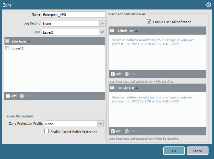
Click OK.
Commit the changes.
2.4.7.2 Configure the GlobalProtect Portal
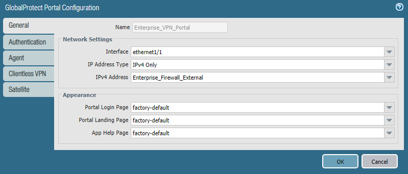
Navigate to Network > GlobalProtect > Portals.
Click Add.
Give the profile a meaningful name, such as Enterprise_VPN_Portal.
For Interface, assign it the firewall’s WAN interface.
Set IP Address Type to IPv4 Only.
Set the IPv4 address to the firewall’s WAN address.
Set all three appearance options to be factory-default.
Figure ‑ GlobalProtect Portal General Configuration
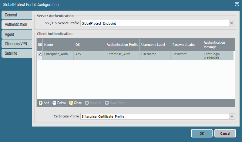
Click Authentication.
Select the created SSL/TLS service profile.
Click Add under Client Authentication.
Give the profile a meaningful name, such as Enterprise_Auth.
Select the created authentication profile next to Authentication Profile.
Click OK.
Figure 2‑41 GlobalProtect Portal Authentication Configuration
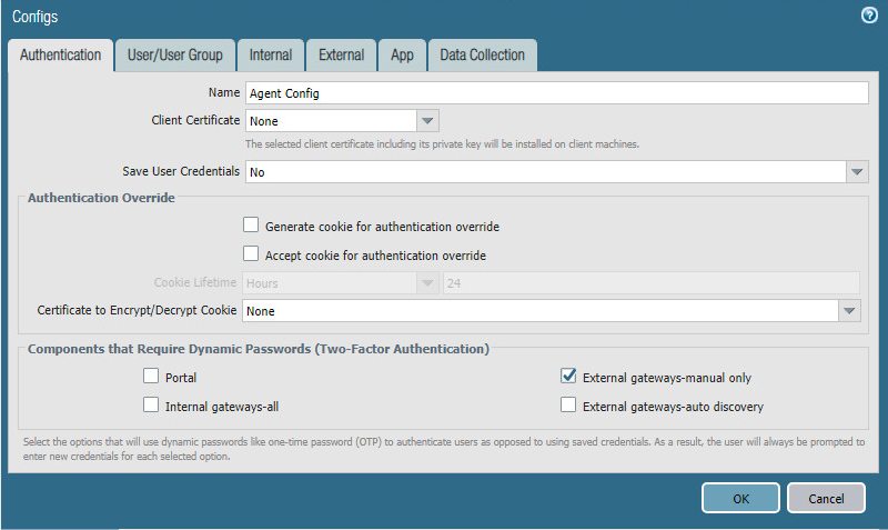
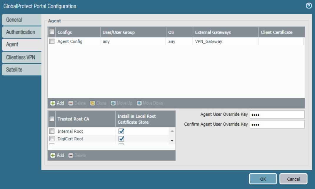
Click Agent and click Add under Agent.
Give the agent configuration a name.
Ensure that the Client Certificate is set to None, and Save User Credentials is set to No.
Check the box next to External gateways-manual only.
Figure 2‑42 GlobalProtect Portal Agent Authentication Configuration
Click External.
Click Add under External Gateways.
Give the gateway a name and enter the fully qualified domain name (FQDN) of the VPN end point.
Click Add under Source Region and select Any.
Check the box next to Manual.
Click OK.
Click App.
Under App Configurations > Connect Method, select On-demand.
Next to Welcome Page, select factory-default.
Click OK.
Click Add under Trusted Root CA.
Select the internal root certificate used to generate device certificates.
Click Add again. Select the root certificate used to create the VPN end-point SSL certificate. For this implementation, it is a DigiCert root certificate.
Click Add again. Select the root certificate used for SSL URL filtering, created in a previous section.
Check the box next to Install in Local Root Certificate Store for all three certificates.
Figure 2‑43 GlobalProtect Portal Agent Configuration
Click OK.
2.4.7.3 Activate Captive Portal
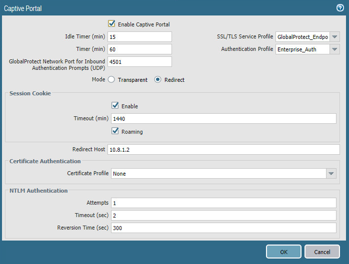
Navigate to Device > User Identification > Captive Portal Settings.
Click the gear icon on the top right of the Captive Portal box.
Select the created SSL/TLS service profile and authentication profile.
Click the radio button next to Redirect.
Next to Redirect Host, enter the IP address of the firewall’s WAN interface—in this case, 10.8.1.2.
Figure 2‑44 Captive Portal Configuration
Click OK.
Commit the changes.
2.4.7.4 Activate the GlobalProtect Client
Navigate to Device > GlobalProtect Client.
Acknowledge pop up messages.
Click Check Now at the bottom of the page.
Click Download next to the first release that comes up. In this implementation, version 5.0.2atewas used.
Click Activate next to the downloaded release.
Navigate to the FQDN of the VPN. You should see the Palo Alto Networks logo and the GlobalProtect portal login prompt, potentially with a message indicating that a required certificate cannot be found. This is expected on desktops because there is nothing in place to seamlessly deploy client certificates.
Figure 2‑45 GlobalProtect Portal
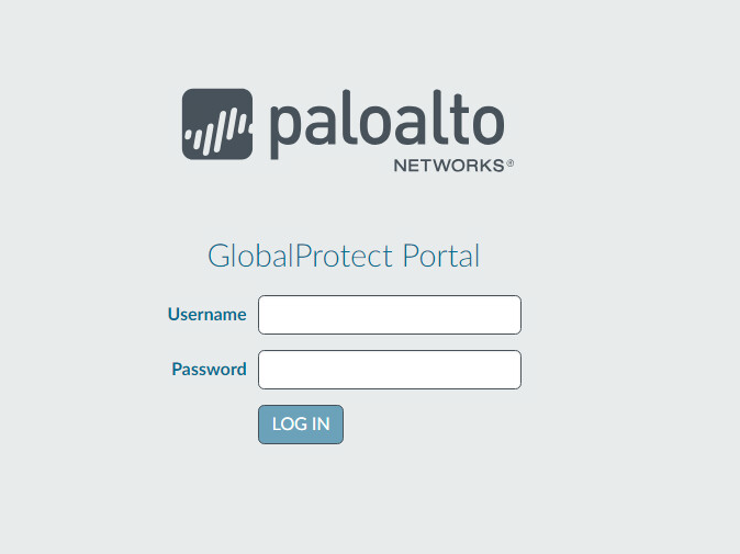
Note: If you intend to use the GlobalProtect agent with a self-signed certificate (e.g., internal PKI), be sure to download the SSL certificate from the VPN website and install it in the trusted root CA store.
2.4.8 Enable Automatic Application and Threat Updates
In the PAN-OS portal, navigate to Device > Dynamic Updates.
Install the latest updates.
At the bottom of the page, click Check Now.
Under Applications and Threats, click Download next to the last item in the list with the latest Release Date. This will take a few minutes.
When the download completes click Close. (Figure 2-46)
Click Install on the first row.
Click Continue Installation, leaving the displayed box unchecked. Installation will take a few minutes.
When the installation completes click Close.
Enable automatic threat updates. (Note: Automatic threat updates are performed in the background and do not require a reboot of the appliance.)
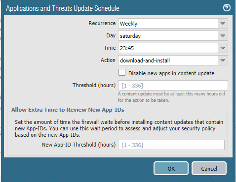
At the top of the page, next to Schedule, click the hyperlink with the date and time, as shown in Figure 2‑47.
Select the desired recurrence. For this implementation, weekly was used.
Select the desired day and time for the update to occur. For this implementation, Saturday at 23:45 was used.
Next to Action, select download-and-install.
Click OK. (Figure 2-48)
Commit the changes.
Figure 2‑46 Downloaded Threats and Applications
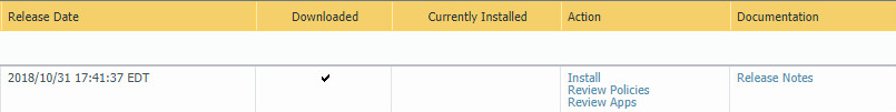
Figure 2‑47 Schedule Time Hyperlink

Figure 2‑48 Application and Threats Update Schedule
2.5 Kryptowire
Kryptowire was used as an application vetting service via a custom active directory-integrated web application.
2.5.1 Kryptowire and MaaS360 Integration
Contact IBM support to provision API credentials for Kryptowire.
Contact Kryptowire support to enable the MaaS360 integration, including the MaaS360 API credentials.
In the Kryptowire portal, click the logged-in user’s email address in the upper right-hand corner of the portal. Navigate to Settings > Analysis.
Set the Threat Score Threshold to the desired amount. In this sample implementation, 75 was used.
Enter an email address where email alerts should be delivered.
Click Save Settings. Kryptowire will now send an email to the email address configured in step 5 when an analyzed application is at or above the configured alert threshold.