NIST SPECIAL PUBLICATION 1800-10B
Protecting Information and System Integrity in Industrial Control System Environments:
Cybersecurity for the Manufacturing Sector
Volume B:
Approach, Architecture, and Security Characteristics
Michael Powell
National Cybersecurity Center of Excellence
National Institute of Standards and Technology
Michael Pease
Keith Stouffer
CheeYee Tang
Timothy Zimmerman
Engineering Laboratory
National Institute of Standards and Technology
Joseph Brule
Chelsea Deane
John Hoyt
Mary Raguso
Aslam Sherule
Kangmin Zheng
The MITRE Corporation
McLean, Virginia
Matthew Zopf
Strativia
Largo, Maryland
March 2022
FINAL
This publication is available free of charge from https://doi.org/10.6028/NIST.SP.1800-10
The first draft of this publication is available free of charge from https://www.nccoe.nist.gov/publications/practice-guide/protecting-information-and-system-integrity-industrial-control-system-draft

DISCLAIMER
Certain commercial entities, equipment, products, or materials may be identified by name or company logo or other insignia in order to acknowledge their participation in this collaboration or to describe an experimental procedure or concept adequately. Such identification is not intended to imply special status or relationship with NIST or recommendation or endorsement by NIST or NCCoE; neither is it intended to imply that the entities, equipment, products, or materials are necessarily the best available for the purpose.
Domain name and IP addresses shown in this guide represent an example domain and network environment to demonstrate the NCCoE project use case scenarios and the security capabilities.
National Institute of Standards and Technology Special Publication 1800-10B, Natl. Inst. Stand. Technol. Spec. Publ. 1800-10B, 149 pages, March 2022, CODEN: NSPUE2
FEEDBACK
As a private-public partnership, we are always seeking feedback on our practice guides. We are particularly interested in seeing how businesses apply NCCoE reference designs in the real world. If you have implemented the reference design, or have questions about applying it in your environment, please email us at manufacturing_nccoe@nist.gov.
All comments are subject to release under the Freedom of Information Act (FOIA).
NATIONAL CYBERSECURITY CENTER OF EXCELLENCE
The National Cybersecurity Center of Excellence (NCCoE), a part of the National Institute of Standards and Technology (NIST), is a collaborative hub where industry organizations, government agencies, and academic institutions work together to address businesses’ most pressing cybersecurity issues. This public-private partnership enables the creation of practical cybersecurity solutions for specific industries, as well as for broad, cross-sector technology challenges. Through consortia under Cooperative Research and Development Agreements (CRADAs), including technology partners—from Fortune 50 market leaders to smaller companies specializing in information technology security—the NCCoE applies standards and best practices to develop modular, easily adaptable example cybersecurity solutions using commercially available technology. The NCCoE documents these example solutions in the NIST Special Publication 1800 series, which maps capabilities to the NIST Cybersecurity Framework (CSF) and details the steps needed for another entity to re-create the example solution. The NCCoE was established in 2012 by NIST in partnership with the State of Maryland and Montgomery County, Maryland.
To learn more about the NCCoE, visit https://www.nccoe.nist.gov/. To learn more about NIST, visit https://www.nist.gov.
NIST CYBERSECURITY PRACTICE GUIDES
NIST Cybersecurity Practice Guides (Special Publication 1800 series) target specific cybersecurity challenges in the public and private sectors. They are practical, user-friendly guides that facilitate the adoption of standards-based approaches to cybersecurity. They show members of the information security community how to implement example solutions that help them align more easily with relevant standards and best practices, and provide users with the materials lists, configuration files, and other information they need to implement a similar approach.
The documents in this series describe example implementations of cybersecurity practices that businesses and other organizations may voluntarily adopt. These documents do not describe regulations or mandatory practices, nor do they carry statutory authority.
ABSTRACT
Today’s manufacturing organizations rely on industrial control systems (ICS) to conduct their operations. Increasingly, ICS are facing more frequent, sophisticated cyber attacks—making manufacturing the second-most-targeted industry [B1]. Cyber attacks against ICS threaten operations and worker safety, resulting in financial loss and harm to the organization’s reputation.
The architecture and solutions presented in this guide are built upon standards-based, commercially available products, and represent some of the possible solutions. The solutions implement standard cybersecurity capabilities such as behavioral anomaly detection (BAD), application allowlisting (AAL), file integrity-checking, change control management, and user authentication and authorization. The solution was tested in two distinct lab settings: a discrete manufacturing workcell, which represents an assembly line production, and a continuous process control system (PCS), which represents chemical manufacturing industries.
An organization that is interested in protecting the integrity of a manufacturing system and information from destructive malware, insider threats, and unauthorized software should first conduct a risk assessment and determine the appropriate security capabilities required to mitigate those risks. Once the security capabilities are identified, the sample architecture and solution presented in this document may be used.
The security capabilities of the example solution are mapped to the NIST Cybersecurity Framework, the National Initiative for Cybersecurity Education Framework, and NIST Special Publication 800-53.
KEYWORDS
Application allowlisting; behavioral anomaly detection; file integrity checking; firmware modification; industrial control systems; manufacturing; remote access; software modification; user authentication; user authorization.
ACKNOWLEDGEMENTS
We are grateful to the following individuals for their generous contributions of expertise and time.
Name |
Organization |
|---|---|
Dan Frechette |
Microsoft |
Ian Schmertzler |
Dispel |
Ben Burke |
Dispel |
Chris Jensen |
Tenable |
Bethany Brower |
VMWare |
Dennis Hui |
OSIsoft (now part of AVEVA) |
John Matranga |
OSIsoft (now part of AVEVA) |
Michael A. Piccalo |
Forescout |
Tim Jones |
Forescout |
Yejin Jang |
Forescout |
Samantha Pelletier |
TDI Technologies |
Rusty Hale |
TDI Technologies |
Steve Petruzzo |
GreenTec |
Josh Carlson |
Dragos |
Alex Baretta |
Dragos |
The Technology Partners/Collaborators who participated in this build submitted their capabilities in response to a notice in the Federal Register. Respondents with relevant capabilities or product components were invited to sign a Cooperative Research and Development Agreement (CRADA) with NIST, allowing them to participate in a consortium to build this example solution. We worked with:
Technology Partner/Collaborator |
Product |
|---|---|
Carbon Black App Control |
|
Azure Defender for the internet of things (IoT) (incorporating technology from the acquisition of CyberX) |
|
Dispel Wicket ESI Dispel Enclave Dispel VDI (Virtual Desktop Interface) |
|
Dragos Platform |
|
eyeInspect (Formerly SilentDefense)
ICS Patrol
EyeSight |
|
WORMdisk and ForceField |
|
PI System (which comprises products such as PI Server, PI Vision and others) |
|
ConsoleWorks |
|
Tenable.ot |
DOCUMENT CONVENTIONS
The terms “shall” and “shall not” indicate requirements to be followed strictly to conform to the publication and from which no deviation is permitted. The terms “should” and “should not” indicate that among several possibilities, one is recommended as particularly suitable without mentioning or excluding others, or that a certain course of action is preferred but not necessarily required, or that (in the negative form) a certain possibility or course of action is discouraged but not prohibited. The terms “may” and “need not” indicate a course of action permissible within the limits of the publication. The terms “can” and “cannot” indicate a possibility and capability, whether material, physical, or causal.
PATENT DISCLOSURE NOTICE
NOTICE: The Information Technology Laboratory (ITL) has requested that holders of patent claims whose use may be required for compliance with the guidance or requirements of this publication disclose such patent claims to ITL. However, holders of patents are not obligated to respond to ITL calls for patents and ITL has not undertaken a patent search in order to identify which, if any, patents may apply to this publication.
As of the date of publication and following call(s) for the identification of patent claims whose use may be required for compliance with the guidance or requirements of this publication, no such patent claims have been identified to ITL.
No representation is made or implied by ITL that licenses are not required to avoid patent infringement in the use of this publication.
List of Figures
Figure 4‑1: CSMS Network Architecture
Figure 4‑2 Simplified Tennessee Eastman Process Model
Figure 4‑3 HMI Screenshot for the PCS Showing the Main Components in the Process
Figure 4‑7 Build 1, PCS Complete Architecture with Security Components
Figure 4‑8 Build 2, PCS Complete Architecture with Security Components
Figure 4‑9 Build 3, CRS Complete Architecture with Security Components
Figure 4‑10 Build 4, CRS Complete Architecture with Security Components
Figure D-1 An Alert from Carbon Black Showing that Malware (1.exe) was Blocked from Executing
Figure D-2: Carbon Black’s Server Provides Additional Details and Logs of the Event
Figure D-3 Carbon Black’s Server Log of the Event
Figure D-4 Windows 7 Alert as a Result of Windows SRP Blocking the Execution of 1.exe
Figure D-5 Windows 10 Alert as a Result of Windows SRP Blocking the Execution of 1.exe
Figure D-6 Carbon Black Blocks the Execution of 1.exe for Build 4
Figure D-7 Tenable.ot Dashboard Showing the Events that were Detected
Figure D-8 Detected RDP Session Activity from External System to DMZ System
Figure D-10 Tenable.ot Detected VNC Connection Between the DMZ and the Testbed LAN
Figure D-12 Detected RDP from a DMZ system to a Testbed LAN system
Figure D-14 Attempt to Execute 1.exe Failed
Figure D-15 Alert Dashboard Showing Detection of an RDP Session
Figure D-16 Details of the Detected RDP Session Activity from an External System to DMZ System
Figure D-17 Detection of Scanning Traffic and RDP Connection into Manufacturing Environment
Figure D-18 Details of One of the Port Scan Alerts
Figure D-19 Details of Alert for RDP Connection into Manufacturing Environment
Figure D-20 Dialog Message Showing 1.exe was Blocked from Executing
Figure D-21 Windows SRP blocked 1.exe From Executing
Figure D-22 Log of Alerts Detected by Dragos
Figure D-23 Detail of RDP Session Activity Between an External System and a DMZ System
Figure D-24 Detail for Network Scanning Alert
Figure D-25 Detail of RDP Session Activity Between a DMZ System and a Testbed LAN System
Figure D-26 Azure Defender for IoT “info” Event Identified Remote Access Connection to the DMZ
Figure D-27 Alert for Scanning Activity
Figure D-28 Details for the Scanning Alert
Figure D-29 Detection of RDP Connection into the Manufacturing Environment
Figure D-30 Carbon Black Shows an Alert for Blocking File 1.exe
Figure D-31 Secured VPN Connection to Environment with Cisco AnyConnect
Figure D-32 Remote Access is Being Established Through ConsoleWorks
Figure D-33 Dispel VDI with Interface for Connecting Through Dispel Enclave to Dispel Wicket ESI
Figure D-34 Nested RDP Session Showing Dispel Connection into the PCS Workstation
Figure D-35 VPN Connection to Manufacturing Environment
Figure D-36 Remote Access is Being Established Through ConsoleWorks
Figure D-37 Dispel VDI Showing Interface for Connecting Through Dispel Enclave to Dispel Wicket
Figure D-38 Nested RDP Session Showing Dispel Connection into the CRS Workstation
Figure D-39 Carbon Black Blocks the Execution of putty.exe and Other Files
Figure D-40 Tenable.ot Alert With the SMB Connection Between the HMI and the GreenTec Server
Figure D-42 Putty.exe is Not Permitted to Run Based on the Windows SRP Configuration
Figure D-43 putty-64bit-0.74-installer.msi is blocked by Windows SRP
Figure D-44 Forescout Alert on the File Transfer Activity
Figure D-45 Forescout Alert Details for the File Transfer Activity
Figure D-46 Putty.exe is Not Permitted to Run Based on the Windows SRP Configuration
Figure D-47 putty-64bit-0.74-installer.msi is Blocked by Windows SRP
Figure D-48 Dragos Alert on the File Transfer Activity
Figure D-49 Dragos Alert Details of the File Transfer Alert
Figure D-50 Carbon Black Alert Showing that putty.exe is Blocked from Executing
Figure D-51 Carbon Black Alert Showing Execution of putty-64bit-0.74-installer.msi Being Blocked
Figure D-52 Azure Defender for IoT Alert Dashboard Showing Detection of a New Activity
Figure D-54 Azure Defender for IoT Event Alert Timeline Showing the File Transfer
Figure D-55 Tenable.ot Event Showing a New Asset has Been Discovered
Figure D-56 Tenable.ot Event Showing Unauthorized SSH Activities
Figure D-57 Forescout Alert on the DNS Request from the New Device
Figure D-58 Forescout alert showing the SSH connection
Figure D-59 Detailed Forescout alert of the Unauthorized SSH Connection
Figure D-60 Dragos Dashboard Showing Alerts Generated upon Detecting New Device and Network Scanning
Figure D-61 Details of Network Scanning Activity
Figure D-62 Additional Details of Network Scanning Activity
Figure D-63 Alert for New Asset on the Network
Figure D-64 Azure Defender for IoT Dashboard Showing the Alerts, Including for the New Asset
Figure D-65 Azure Defender for IoT Detects New Asset in the Environment
Figure D-66 Azure Defender for IoT Alert Management Options
Figure D-67 Details for Network Scanning Alert
Figure D-68 Tenable.ot Event Log Showing the Unapproved SSH Traffic
Figure D-69 Forescout Alert Showing the Unapproved SSH Traffic
Figure D-70 Dragos Alert Showing the Unapproved SSH Connection Between Devices
Figure D-71 Azure Defender for IoT Event Identified the Unauthorized SSH Connection
Figure D-72 Event Messages from Carbon Black Showing File Deletion Attempts
Figure D-73 Security Onion Wazuh Alert Showing a File Has Been Deleted
Figure D-74 Alert from Security Onion for a File Deletion
Figure D-75 Carbon Black Alerts Showing That a File Has Been Deleted
Figure D-76 Remote Access to Systems in PCS Network is Established Through ConsoleWorks
Figure D-77 Remote Session into Studio 5000 to Perform PLC File Operations
Figure D-78 Tenable.ot Detected the Transfer of PLC Logic File to the Rockwell PLC
Figure D-79 Tenable.ot PLC Stop alert details
Figure D-80 Tenable.ot PLC Program Download Alert Details
Figure D-81 Remote Access to Systems in PCS Network is Being Established Through Dispel
Figure D-82 Modifying the Parameters for the Allen-Bradley PLC Controller Using Studio 5000
Figure D-84 Forescout Alert Details for the Stop Command Issued to the PLC
Figure D-85 Forescout Alert Details for the Configuration Download Command
Figure D-86 VPN Connection to the Manufacturing Environment
Figure D-87 Remote Access is Being Established through ConsoleWorks
Figure D-89 Dragos Alert Details for the PLC Logic File Download
Figure D-90 Dispel VDI with Interface for Connecting Through Dispel Enclave to Dispel Wicket
Figure D-91 Nested RDP Connections Showing Dispel Connection into the CRS Workstation
Figure D-92 Azure Defender for IoT Alert for Unauthorized PLC Programming
Figure D-93 Tenable.ot alert Shows SMB Connection from External Workstation to the Historian
Figure D-94 GreenTec Denies Modification and Deletion File Operations in the Protected Drive
Figure D-95 Forescout Alert Shows Network Connection from Corporate Network to the Historian
Figure D-96 GreenTec Denies Modification and Deletion File Operations in the Protected Drive
Figure D-97 Dragos Detection of RDP Session from an External Network to the Historian
Figure D-98 GreenTec Denies Modification and Deletion File Operations in the Protected Drive
Figure D-100 GreenTec Denies Modification and Deletion File Operations in the Protected Drive
Figure D-101 PI Server’s Event Frames Showing Out-of-Range Sensor Readings for the Reactor Pressure
Figure D-102 Tenable.ot Detects a Collection of Events Generated by a Firmware Change
Figure D-103 Details for One of the Alerts Showing the Firmware Change
Figure D-104 Forescout Detects a Collection of Alerts Associated with the Firmware Change
Figure D-105 Alert Details Detected by Forescout for the Firmware Change
Figure D-106 ICS Patrol Scan Results Showing a Change Configuration was Made
Figure D-107 Dragos Dashboard Showing an Alert for Firmware Change
Figure D-108 Details for Firmware Change Alert
Figure D-109 Azure Defender for IoT Alert Showing a Version Mismatch in the Firmware Build
List of Tables
Table 3‑1 Security Control Map
Table 3‑2 Products and Technologies
Table 4‑1 Summary of What Products Were Used in Each Build
Table 4‑2 Build 1 Technology Stack to Capabilities Map
Table 4‑3 Build 2 Technology Stack to Capabilities Map
Table 4‑4 Build 3 Technology Stack to Capabilities Map
Table 4‑5 Build 4 Technology Stack to Capabilities Map
1 Summary
While availability is always a critical aspect of manufacturing system environments, manufacturers also need to consider maintaining the integrity of their systems and information to ensure continued operations. The integrity of information can be degraded or lost as a result of behaviors by authorized users (e.g., failure to perform backups or record their actions) or malicious actors seeking to disrupt manufacturing operations for illicit profits, political statements, or other reasons.
Manufacturers are unique because of their reliance on industrial control systems (ICS) to monitor and control their manufacturing operations. ICS typically prioritize information availability and integrity over confidentiality. As a result, cybersecurity solutions used in traditional information technology (IT) settings are not optimized to protect ICS from cyber threats.
This guide, prepared by the National Cybersecurity Center of Excellence (NCCoE) and the NIST Engineering Laboratory (EL), contains four examples of practical solutions that organizations can implement in their environments to protect ICS from information and system integrity attacks.
The goal of this NIST Cybersecurity Practice Guide is to help organizations protect the integrity of systems and information by:
securing historical system data
preventing execution or installation of unapproved software
detecting anomalous behavior on the network
identifying hardware, software, or firmware modifications
enabling secure remote access
authenticating and authorizing users
This document provides a detailed description of how each solution was implemented and what technologies were used to achieve each of the above listed goals across four example builds. Scenarios are used to demonstrate the efficacy of the solutions. The results and challenges of each scenario in the four example builds are also presented and discussed.
Ultimately, manufacturing organizations that rely on ICS can use the example solutions described in this guide to safeguard their information and system integrity from:
destructive malware
insider threats
unauthorized software
unauthorized remote access
loss of historical data
anomalous network traffic
unauthorized modification of systems
This document contains the following sections:
Section 1, Summary, presents the challenges addressed by the NCCoE project, with a look at the solutions demonstrated to address the challenge, as well as benefits of the solutions.
Section 2, How to Use This Guide, explains how readers—business decision makers, program managers, control system engineers, cybersecurity practitioners, and IT professionals (e.g., systems administrators)— might use each volume of this guide.
Section 3, Approach, offers a description of the intended audience and the scope of the project. This section also describes the assumptions on which the security architecture and solution development was based, the risk assessment that informed architecture development, the NIST Cybersecurity Framework functions supported by each component of the architecture and reference design, and which industry collaborators contributed support in building, demonstrating, and documenting the solutions. This section also includes a mapping of the NIST Cybersecurity Framework Subcategories to other industry guidance, and identifies the products used to address each subcategory.
Section 4, Architecture, summarizes the Cybersecurity for Smart Manufacturing Systems (CSMS) demonstration environment, which emulates real-world manufacturing processes and their ICS by using software simulators and commercial off-the-shelf hardware in a laboratory environment. The implementation of the information and system integrity solutions is also described.
Section 5, Security Characteristic Analysis, summarizes the scenarios and findings that were employed to demonstrate the example implementations’ functionality. Each of the scenarios is mapped to the relevant NIST Cybersecurity Framework functions and Subcategories and the security capabilities of the products that were implemented. Additionally, it briefly describes how the security capabilities that were used in the solution implementation help detect cyber attacks and protect the integrity of the manufacturing systems and information.
Section 6, Future Build Considerations, identifies additional areas that should be reviewed in future practice guides.
Section Appendix D, Scenario Execution Results, describes, in detail, the test results of the scenarios, including screenshots from the security products captured during the tests.
1.1 Challenge
Manufacturing organizations that rely on ICS to monitor and control physical processes face risks from malicious and non-malicious insiders along with external threats in the form of increasingly sophisticated cyber attacks. A compromise to system or information integrity may very well pose a significant threat to human safety and can adversely impact an organization’s operations, resulting in financial loss and harm production for years to come.
Manufacturing organizations may be the targets of malicious cyber actors or may be incidentally impacted by a broader malware event such as ransomware attacks. ICS components remain vulnerable to cyber attacks for numerous reasons, including adoption and integration of enhanced connectivity, remote access, the use of legacy technologies, flat network topologies, lack of network segmentation, and the lack of cybersecurity technologies (e.g., anti-virus, host-based firewalls, encryption) typically found on IT systems.
Organizations are increasingly adopting and integrating IT into the ICS environment to enhance connectivity to business systems and to enable remote access. As a result, ICS are no longer isolated from the outside world, making them more vulnerable to cyber attacks. Security controls designed for the IT environment may impact the performance of ICS when implemented within the operational technology (OT) environment, so special precautions are required when introducing these controls. In some cases, new security techniques tailored to the specific ICS environment are needed.
Another challenge facing manufacturing organizations comes from authorized users who accidentally or intentionally compromise information and system integrity. For example, a user may install an unapproved software utility to perform maintenance activities or update the logic of a programmable logic controller (PLC) to fix a bug. Even if the software or logic changes are not malicious, they may inadvertently disrupt information flows, starve critical software of processing resources, or degrade the operation of the system. In a worst-case scenario, malware may be inadvertently installed on the manufacturing system, causing disruptions to system operations, or opening a backdoor to remote attackers.
1.2 Solution
This NCCoE Cybersecurity Practice Guide demonstrates how manufacturing organizations can use commercially available technologies that are consistent with cybersecurity standards to detect and prevent cyber incidents on their ICS.
Manufacturers use a wide range of ICS equipment and manufacturing processes. This guide contains four different example solutions that are applicable to a range of manufacturing environments, focusing on discrete and continuous manufacturing processes.
This project provides example solutions, composed of the following capabilities, for manufacturing environments:
application allowlisting (AAL)
behavior anomaly detection (BAD)
file integrity
user authentication and authorization
remote access
1.2.1 Relevant Standards and Guidance
The solutions presented in this guide are consistent with the practices and guidance provided by the following references:
NIST Special Publication (SP) 800-167: Guide to Application Whitelisting [B2]
Department of Homeland Security, Critical Manufacturing Sector Cybersecurity Framework Implementation Guidance [B3]
Executive Order no. 13636: Improving Critical Infrastructure Cybersecurity [B4]
NIST, Framework for Improving Critical Infrastructure Cybersecurity [B5]
NIST Interagency Report (NISTIR) 8219: Securing Manufacturing Industrial Control Systems: Behavioral Anomaly Detection [B6]
NIST Internal Report (NISTIR) 8183: Cybersecurity Framework Manufacturing Profile [B7]
NISTIR 8089: An Industrial Control System Cybersecurity Performance Testbed [B8]
NIST SP 800-53 Rev. 5: Security and Privacy Controls for Federal Information Systems and Organizations [B9]
NIST SP 800-181: National Initiative for Cybersecurity Education (NICE) Cybersecurity Workforce Framework [B10]
NIST Special Publication 1800-25: Data Integrity: Identifying and Protecting Assets Against Ransomware and Other Destructive Events [B11]
NIST Interagency or Internal Report 7298 Rev 3: Glossary of Key Information Security Terms [B12]
U.S.-Canada Power System Outage Task Force [B13]
NIST SP 800-82 Rev. 2: Guide to Industrial Control Systems (ICS) Security [B14]
1.3 Benefits
This NCCoE practice guide can help organizations:
mitigate cybersecurity risk
reduce downtime for operations
provide a reliable environment that can detect cyber anomalies
respond to security alerts through automated cybersecurity-event products
develop and execute an OT cybersecurity strategy for which continuous OT cybersecurity monitoring is a foundational building block
implement current cybersecurity standards and best practices
2 How to Use This Guide
This NIST Cybersecurity Practice Guide demonstrates a modular design and provides users with the information they need to replicate the described manufacturing ICS security solutions, specifically focusing on information and system integrity. This reference design is modular and can be deployed in whole or in part.
This guide contains three volumes:
NIST SP 1800-10A: Executive Summary
NIST SP 1800-10B: Approach, Architecture, and Security Characteristics – what we built and why (this document)
NIST SP 1800-10C: How-To Guide – instructions for building the example solution
Depending on your role in your organization, you might use this guide in different ways:
Senior information technology (IT) executives, including chief information security and technology officers, will be interested in the Executive Summary, NIST SP 1800-10A, which describes the following topics:
challenges that enterprises face in ICS environments in the manufacturing sector
example solution built at the NCCoE
benefits of adopting the example solution
Technology or security program managers might share the Executive Summary, NIST SP 1800-10A, with your leadership to help them understand the importance of adopting a standards-based solution. Doing so can strengthen their information and system integrity practices by leveraging capabilities that may already exist within their operating environment or by implementing new capabilities.
Technology or security program managers who are concerned with how to identify, understand, assess, and mitigate risk will be interested in NIST SP 1800-10B (this document), which describes what we did and why. The following section will be of particular interest:
Section 3.4.4, which maps the security characteristics of the example solutions to cybersecurity standards and best practices
IT and OT professionals who want to implement an approach like this will find the whole practice guide useful, particularly the how-to portion, NIST SP 1800-10C, which provides step-by-step details to replicate all, or parts of the example solutions created in our lab. Volume C does not re-create the product manufacturers’ documentation, which is generally widely available. Rather, Volume C shows how we integrated the products together to create an example solution.
This guide assumes that IT and OT professionals have experience implementing security products within the enterprise. While we have used a suite of commercial products to address this challenge, this guide does not endorse these particular products. Your organization can adopt this solution or one that adheres to these guidelines in whole, or you can use this guide as a starting point for tailoring and implementing parts of the manufacturing ICS solution. Your organization’s security experts should identify the products that will best integrate with your existing tools and IT system infrastructure. We hope that you will seek products that are congruent with applicable standards and best practices. Section 3.5, Technologies, lists the products we used and maps them to the cybersecurity controls provided by this reference solution.
A NIST Cybersecurity Practice Guide does not describe “the” solution. Every organization is unique in its priorities, risk tolerance, and the cyber ecosystem they operate in. This document presents a possible solution that may be tailored or augmented to meet an organization’s own needs.
This document provides initial guidance. We seek feedback on its contents and welcome your input. Comments, suggestions, and success stories will improve subsequent versions of this guide. Please contribute your thoughts to manufacturing_nccoe@nist.gov.
2.1 Typographic Conventions
The following table presents typographic conventions used in this volume.
Typeface/ Symbol |
Meaning |
Example |
|---|---|---|
Italics |
file names and path names; references to documents that are not hyperlinks; new terms; and placeholders |
For language use and style guidance, see the NCCoE Style Guide. |
Bold |
names of menus, options, command buttons, and fields |
Choose File > Edit. |
Monospace |
command-line input, onscreen computer output, sample code examples, and status codes |
|
Monospace (block) |
multi-line input, on-screen computer output, sample code examples, status codes |
% mkdir -v nccoe_projects
mkdir: created directory 'nccoe_projects'
|
blue text |
link to other parts of the document, a web URL, or an email address |
All publications from NIST’s NCCoE are available at https://www.nccoe.nist.gov. |
3 Approach
This practice guide documents the approach the NCCoE used to develop example solutions, called builds, to support information and system integrity objectives. The approach includes a logical design, example build development, testing, security control mapping, and analysis.
Based on our discussions with cybersecurity practitioners in the manufacturing sector, the NCCoE pursued the Information and System Integrity in ICS Environments project to illustrate the broad set of capabilities available to manage and protect OT assets.
The NCCoE collaborated with the NIST Engineering Lab (EL), Community of Interest (COI) members, and the participating vendors to produce an example architecture and its corresponding implementations. Vendors provided technologies that met project requirements and assisted in installation and configuration of those technologies. This practice guide highlights the implementation of example architectures, including supporting elements such as functional tests, security characteristic analysis, and future build considerations.
3.1 Audience
This guide is intended for individuals or entities responsible for cybersecurity of ICS and for those interested in understanding information and system integrity capabilities for OT and how one approaches the implementation of an architecture. It may also be of interest to anyone in industry, academia, or government who seeks general knowledge of an OT information and system integrity solution for manufacturing-sector organizations.
3.2 Scope
This document focuses on information and system integrity in ICS environments typical of manufacturing organizations. It provides real-world guidance on implementing a solution for manufacturing ICS environments.
The scope of this project is to assist organizations in maintaining the integrity of information and systems by:
Preventing execution or installation of unapproved software
preventing unauthorized access to systems and information
detecting anomalous behavior on the network that affects system or information integrity
detecting hardware, software, or firmware modification
Organizational cybersecurity policies and procedures, as well as response and recovery functions, are out of scope for this document. The scenarios and security capabilities covered in this practice guide should be part of a comprehensive OT/ICS security plan that addresses the NIST Cybersecurity Framework Protect and Detect functions.
The security capabilities used in this demonstration for protecting information and system integrity in ICS environments are briefly described below. These capabilities are implemented using commercially available third-party and open source solutions that provide the following capabilities:
Application Allowlisting (AAL): A list of applications and application components (libraries, configuration files, etc.) that are authorized to be present or active on a host according to a well-defined baseline. [B2]
Behavioral Anomaly Detection (BAD): A mechanism providing a multifaceted approach to detecting cybersecurity attacks. [B6]
Hardware/Software/Firmware Modification Detection: A mechanism providing the ability to detect changes to hardware, software, and firmware on systems or network connected devices.
File Integrity Checking: A mechanism providing the ability to detect changes to files on systems or network-connected devices.
User Authentication and Authorization: A mechanism for verifying the identity and the access privileges granted to a user, process, or device. [B12]
Remote Access: A mechanism supporting access to an organizational information system by a user (or an information system acting on behalf of a user) communicating through an external network (e.g., the Internet). [B12]
3.3 Assumptions
This project makes the following assumptions:
Each solution is comprised of several readily available products. The modularity of the solutions might allow organizations to consider swapping one or more products, depending on their specific requirements.
A cybersecurity stakeholder might implement all or part of a solution in a manner that is compatible with their existing environment.
Organizations will test and evaluate the compatibility of the solutions with their ICS devices prior to production implementation and deployment. Response and recovery functions are beyond the scope of this guide.
Events detected by the security tools are passed on to the security operation team for further action.
3.4 Risk Assessment
NIST SP 800-30 Revision 1, Guide for Conducting Risk Assessments, states that risk is “a measure of the extent to which an entity is threatened by a potential circumstance or event, and typically a function of: (i) the adverse impacts that would arise if the circumstance or event occurs; and (ii) the likelihood of occurrence.” The guide further defines risk assessment as “the process of identifying, estimating, and prioritizing risks to organizational operations (including mission, functions, image, reputation), organizational assets, individuals, other organizations, and the Nation, resulting from the operation of an information system. Part of risk management incorporates threat and vulnerability analyses, and considers mitigations provided by security controls planned or in place.”
The NCCoE recommends that any discussion of risk management, particularly at the enterprise level, begins with a comprehensive review of NIST SP 800-37 Revision 2, Risk Management Framework for Information Systems and Organizations, material that is available to the public. The Risk Management Framework (RMF) guidance, as a whole, proved to be invaluable in giving us a baseline to assess risks, from which we developed the project, the security characteristics of the build, and this guide.
3.4.1 Threats
A threat is “any circumstance or event with the potential to adversely impact organizational operations” [B11]. Within an IT environment, threats are typically thought of in terms of threats to confidentiality, integrity, or availability.
The realization of a threat to confidentiality, integrity, and availability may have different impacts to the OT versus the IT environments. OT environments are sensitive to loss of safety, availability, and integrity, while traditional IT environments tend to direct more resources toward confidentiality. Organizations that combine IT and OT operations are advised to evaluate the threats from both perspectives.
In a cyber-physical system, cybersecurity stakeholders are advised to consider events that occur in the OT environment may have impact to physical assets and events that occur in the physical world may impact the OT environment. For example, in 2021 a ransomware attack against an American oil pipeline system led to a disruption of operations and ultimately resulted in fuel shortages at airports and filling stations on the United States east coast. At the time of this writing, a full assessment has not been completed, but the economic impact to the pipeline was substantial.
An integrity loss need not be malicious to cause a significant impact. For example, a race condition in a supervisory control and data acquisition (SCADA) program caused a loss of information integrity. This led to alarm and notification failures and ultimately caused the Northeast Blackout of 2003. In excess of 55 million people were affected by this blackout and more than 100 people died. [B13] Similarly, a sensor or metrology malfunction can lead to corrupted values in databases, logs, or other repositories.
Examples of integrity loss that may have an impact on the physical system include:
Data corruption of alarm thresholds or control setpoints may lead to poor production quality in products or, in the extreme case, damage and destruction to physical manufacturing equipment.
A loss of integrity of telemetry data may cause control algorithms to produce erroneous or even detrimental commands to manufacturing or control equipment.
Corrupted routing tables or a denial-of-service attack on the communications infrastructure may cause the manufacturing processes to enter into a fail-safe state, thus inhibiting production. If the process is not designed to be fail-safe, an attack could result in equipment damage and lead to a greater disaster.
Unauthorized remote access to the plant network could enable an attacker to stop production or operate the plant and equipment beyond its intended operating range. An attacker succeeding in disabling the safety instrument systems or changing its threshold parameters—operating the plant beyond its intended range—could lead to severe equipment damage.
3.4.2 Vulnerabilities
A vulnerability as defined in NISTIR 7298, Glossary of Key Information Security Terms [B12] is a “weakness in an information system, system security procedures, internal controls, or implementation that could be exploited by a threat source.”
As indicated in Section 1 of this document, when IT and OT environments are integrated, each domain inherits the vulnerabilities of the other. Increasing complexity of the interfaces typically results in the vulnerability of the overall system being much greater than the sum of the vulnerabilities of the subsystems.
NIST SP 800-82 categorizes ICS vulnerabilities into the following categories with examples [B14]:
Policy and Procedure: incomplete, inappropriate, or nonexistent security policy, including its documentation, implementation guides (e.g., procedures), and enforcement
Architecture and Design: design flaws, development flaws, poor administration, and connections with other systems and networks
Configuration and Maintenance: misconfiguration and poor maintenance
Physical: lack of or improper access control, malfunctioning equipment
Software Development: improper data validation, security capabilities not enabled, inadequate authentication privileges
Communication and Network: nonexistent authentication, insecure protocols, improper firewall configuration
The first step in understanding the vulnerabilities and securing an organization’s ICS infrastructure is knowledge of deployed assets and their interfaces. The knowledge of an asset’s location and baselining its behavior enable detection of anomalous behavior, via network monitoring, that may be the result of a successfully exploited vulnerability. The ability to reliably detect changes in asset behavior and knowing an asset’s attributes are key in responding to potential cybersecurity incidents.
3.4.3 Risk
The risk to an organization is the intersection of:
the vulnerabilities and threats to the organization
the likelihood that the vulnerability and threat event will be realized
the impact to the organization should the event be realized
A meaningful risk assessment must be performed in the context of the cyber-ecosystem and the impact to an organization should a loss or degradation occur. The usefulness of the risk assessment is limited by how well the organization identifies and prioritizes the criticality of its assets, identifies the threats, and estimates the likelihood of the threats being realized.
Though risk analysis is a mature discipline, careful deliberations and analyses are necessary to determine the effect integrating IT and OT assets has on the threats, vulnerabilities, and impact to the organization. Once a baseline risk assessment has been completed, information assurance controls, such as the integrity protection measures investigated in this project, can be evaluated on how well they reduce the likelihood of the threat and subsequent reduction of risk. Cybersecurity stakeholders are strongly encouraged to leverage the NIST Cybersecurity Framework and manufacturing overlays to identify the components, elements, or items for which a risk assessment must be conducted. In addition, NIST SP 800-82 [B14] mentions special considerations for performing an ICS risk assessment.
3.4.4 Security Control Map
Implementation of cybersecurity architectures is most effective when executed in the context of an overall cybersecurity framework. Frameworks include a holistic set of activities or functions (i.e., what needs to be done) and a selection of controls (i.e., how these are done) that are appropriate for a given cyber-ecosystem. For this project, the NIST Cybersecurity Framework provided the overarching framework.
The subset of NIST Cybersecurity Framework Functions, Categories, and Subcategories that are supported by this example solution are listed below in Table 3-1, along with the subset of mappings to NIST SP 800-53 Rev. 5 and to the National Initiative for Cybersecurity Education (NICE) Workforce Framework. NIST SP 800-53 Rev 5: Security and Privacy Controls for Information Systems and Organizations provides a list of controls for protecting operations, assets, and individuals. The controls detail requirements necessary to meet organizational needs. The NICE Cybersecurity Workforce Framework identifies knowledge, skills, and abilities needed to perform cybersecurity tasks. It is a reference guide on how to recruit and retain talent for various cybersecurity roles.
For more information on the security controls, the NIST SP 800-53 Rev.5, Security and Privacy Controls for Information Systems and Organizations is available at https://csrc.nist.gov/publications/detail/sp/800-53/rev-5/final.
For more information about NICE and resources that are available to employers, education and training providers, students, and job seekers, the NIST SP-181 Rev. 1, NICE Cybersecurity Workforce Framework, and other NICE resources are available at https://nist.gov/itl/applied-cybersecurity/nice/nice-framework-resource-center.
3‑1 Security Control Map
Function |
Category |
Subcategory |
NIST SP 800-53 Rev.5 |
NIST SP 800-181 Rev. 1 (NICE Framework) Work Roles |
|---|---|---|---|---|
PROTECT (PR) |
Identity Management, Authentication, and Access Control (PR.AC): Access to physical and logical assets and associated facilities is limited to authorized users, processes, and devices, and is managed consistent with the assessed risk of unauthorized access to authorized activities and transactions. |
PR.AC-1: Identities and credentials are issued, managed, verified, revoked, and audited for authorized devices, users, and processes |
IA-2,
IA-4,
IA-5,
IA-7,
IA-9,
IA-10,
IA-12
|
SP-DEV-001,
OM-ADM-001,
OV-PMA-003
|
PR.AC-3: Remote access is managed |
AC-17,
AC-19
|
SP-SYS-001,
OM-ADM-001,
PR-INF-001
|
||
PR.AC-4: Access permissions and authorizations are managed, incorporating the principles of least privilege and separation of duties |
AC-2,
AC-3,
AC-14,
AC-24
|
OM-STS-001,
OM-ADM-001
|
||
PR.AC-7: Users, devices, and other assets are authenticated (e.g., single-factor, multi-factor) commensurate with the risk of the transaction (e.g., individuals’ security and privacy risks and other organizational risks) |
AC-14,
IA-2,
IA-4,
IA-5
|
OM-STS-001,
OM-ADM-001
|
||
Data Security (PR.DS): Information and records (data) are managed consistent with the organization’s risk strategy to protect the confidentiality, integrity, and availability of information. |
PR.DS-1: Data-at-rest is protected |
MP-7,
SC-28
|
SP-DEV-002,
SP-SYS-002,
OM-DTA-001
|
|
PR.DS-6: Integrity checking mechanisms are used to verify software, firmware, and information integrity |
SI-7
|
OM-DTA-001
|
||
Information Protection Processes and Procedures (PR.IP): Security policies (that address purpose, scope, roles, responsibilities, management commitment, and coordination among organizational entities), processes, and procedures are maintained and used to manage protection of information systems and assets. |
PR.IP-4: Backups of information are conducted, maintained, and tested |
CP-9
|
SP-SYS-001,
SP-SYS-002,
OM-DTA-001
|
|
Maintenance (PR.MA): Maintenance and repairs of industrial control and information system components is performed consistent with policies and procedures. |
PR.MA-1: Maintenance and repair of organizational assets are performed and logged, with approved and controlled tools |
MA-3
|
SP-SYS-001,
OM-ANA-001
|
|
PR.MA-2: Remote maintenance of organizational assets is approved, logged, and performed in a manner that prevents unauthorized access. |
MA-4
|
SP-SYS-001,
OM-ANA-001
|
||
DETECT (DE) |
Anomalies and Events (DE.AE): Anomalous activity is detected in a timely manner and the potential impact of events is understood. |
DE.AE-1: A baseline of network operations and expected data flows for users and systems is established and managed |
CM-2,
SI-4
|
SP-ARC-001,
PR-CDA-001
|
DE.AE-2: Detected events are analyzed to understand attack targets and methods |
CA-7,
SI-4,
RA-5
|
OM-DTA-002,
PR-CDA-001,
CO-OPS-001
|
||
DE.AE-3: Event data are collected and correlated from multiple sources and sensors |
CA-7,
SI-4
|
OM-DTA-002,
PR-CDA-001,
PR-CIR-001,
CO-OPS-001
|
||
Security Continuous Monitoring (DE.CM): The information system and assets are monitored at discrete intervals to identify cybersecurity events and verify the effectiveness of protective measures. |
DE.CM-1: The network is monitored to detect potential cybersecurity events |
AU-12,
CA-7,
CM-3,
SC-7,
SI-4
|
OM-NET-001,
PR-CDA-001,
PR-CIR-001
|
|
DE.CM-3: Personnel activity is monitored to detect potential cybersecurity events |
AU-12,
CA-7,
CM-11
|
PR-CDA-001,
AN-TWA-001
|
||
DE.CM-7: Monitoring for unauthorized personnel, connections, devices, and software is performed |
AU-12,
CA-7,
CM-3,
SI-4
|
PR-CDA-001,
PR-CIR-001,
AN-TWA-001,
CO-OPS-001
|
3.5 Technologies
Table 3‑2 lists the capabilities demonstrated in this project, the products, and their functions, along with a mapping of the capabilities to the NIST Cybersecurity Framework. Refer to Table 3‑1 for an explanation of the NIST Cybersecurity Framework subcategory codes.
Table 3‑2 Products and Technologies
Capability |
Product |
Function |
NIST Cybersecurity Framework Subcategories Mapping |
|---|---|---|---|
AAL |
VMWare Carbon Black |
Allow approved ICS applications to execute. |
DE.AE-2, DE.AE-3, DE.CM-3, DE.CM-7 |
Windows Software Restriction Policies (SRP) (Note: This component was not provided by collaborator. It is a feature of the Windows operating system product.) |
|||
File Integrity Checking |
GreenTec WORMdisk and ForceField |
Provides immutable storage for data, system, and configuration files. |
PR.DS-1, PR.IP-4, PR.MA-1 |
VMWare Carbon Black |
Provides integrity checks for files and software. |
PR.DS-6, PR.MA-1, DE.AE-2, DE.CM-3 |
|
Wazuh Security Onion (Note: This component was not provided by collaborator. It is an open source product.) |
|||
BAD, Hardware/ Software/ Firmware Modification Detection |
Microsoft Azure Defender for IoT |
Passively scans the OT network to create a baseline of devices and network traffic. Alerts when activity deviates from the baseline. |
PR.DS-6, PR.MA-1, DE.AE-1, DE.AE-2, DE.AE-3, DE.CM-1, DE.CM-3, DE.CM-7 |
Dragos Platform |
|||
Forescout eyeInspect (formerly SilentDefense) |
|||
Tenable Tenable.ot |
|||
PI System |
Collects, analyzes, and visualizes time-series data from multiple sources. Alerts when activity deviates from the baseline. |
PR.IP-4, PR.MA-1, DE.AE-1, DE.AE-2, DE.AE-3 |
|
User Authentication and User Authorization |
TDi ConsoleWorks |
Provides a central location for managing password changes. Provides a security perimeter for all devices within the OT environment. |
PR.AC-1, PR.AC-3, PR.AC-4, PR.MA-1, PR.MA-2, DE.AE-2, DE.AE-3, DE.CM-3, DE.CM-7 |
Dispel |
|||
Remote Access |
Dispel |
Provides secure remote access. Records and logs user activity for each session. |
PR.AC-3, PR.MA-2, DE.AE-2, DE.CM-7 |
Cisco AnyConnect (Note: This component was not provided by collaborator. It was a component of the existing lab infrastructure.) |
4 Architecture
These mechanisms and technologies were integrated into the existing NIST CSMS lab environment [B8]. This cybersecurity performance testbed for ICS is comprised of the Process Control System (PCS) and the Collaborative Robotic System (CRS) ICS environments along with additional networking capabilities to emulate common manufacturing environments.
Typically, manufacturing organizations have unique cyber-ecosystems and specific needs for their operation. To demonstrate the modularity and interoperability of the provided solutions, this project used available CRADA partner technologies to assemble four “builds” deployed across both the PCS and CRS. Additionally, to increase the diversity of technologies between builds, two of the builds also utilized open source solutions (Security Onion Wazuh), native operating system features (Windows SRP), and a Cisco Adaptive Security Appliance (ASA) device configured with the AnyConnect virtual private network (VPN) client.
This modular approach, focusing on specific products and outcomes, demonstrates how solutions might be tailored to the operating environment. Table 4‑1 provides a summary of the four builds and how the products were distributed across them. Detailed descriptions of the installation, configuration, and integration of these builds are included in Volume C of this guide.
Table 4‑1 Summary of What Products Were Used in Each Build
Capability |
Build 1 |
Build 2 |
Build 3 |
Build 4 |
|---|---|---|---|---|
PCS |
CRS |
|||
AAL |
Carbon Black |
Windows SRP |
Windows SRP |
Carbon Black |
BAD, Hardware/Software/Firmware Modification Detection |
PI Server |
PI Server |
PI Server |
PI Server |
Tenable.ot |
eyeInspect |
Dragos |
Azure Defender for IoT |
|
File Integrity Checking |
Carbon Black |
Wazuh |
Wazuh |
Carbon Black |
ForceField, WORMdisk |
ForceField, WORMdisk |
ForceField, WORMdisk |
ForceField, WORMdisk |
|
User Authentication and Authorization |
ConsoleWorks |
Dispel |
ConsoleWorks |
Dispel |
Remote Access |
AnyConnect |
Dispel |
AnyConnect |
Dispel |
Sections 4.1, 4.2, 4.3, and 4.4, present descriptions of the manufacturing processes and control systems of the testbed that are used for demonstrating the security capabilities required for protecting information and system integrity in ICS environments. Section 4.5 describes the network and security architectures that are used to implement the above security capabilities.
4.1 Manufacturing Process and Control System Description
The CSMS demonstration environment emulates real-world manufacturing processes and their ICS by using software simulators and commercial off-the-shelf (COTS) hardware in a laboratory environment [B8]. The CSMS environment was designed to measure the performance impact on ICS that is induced by cybersecurity technologies. For this effort, the CSMS and the integrated PCS and CRS are used to demonstrate the information and system integrity capabilities and are described in Sections 4.3 and 4.4.
4.2 Cybersecurity for Smart Manufacturing Systems Architecture
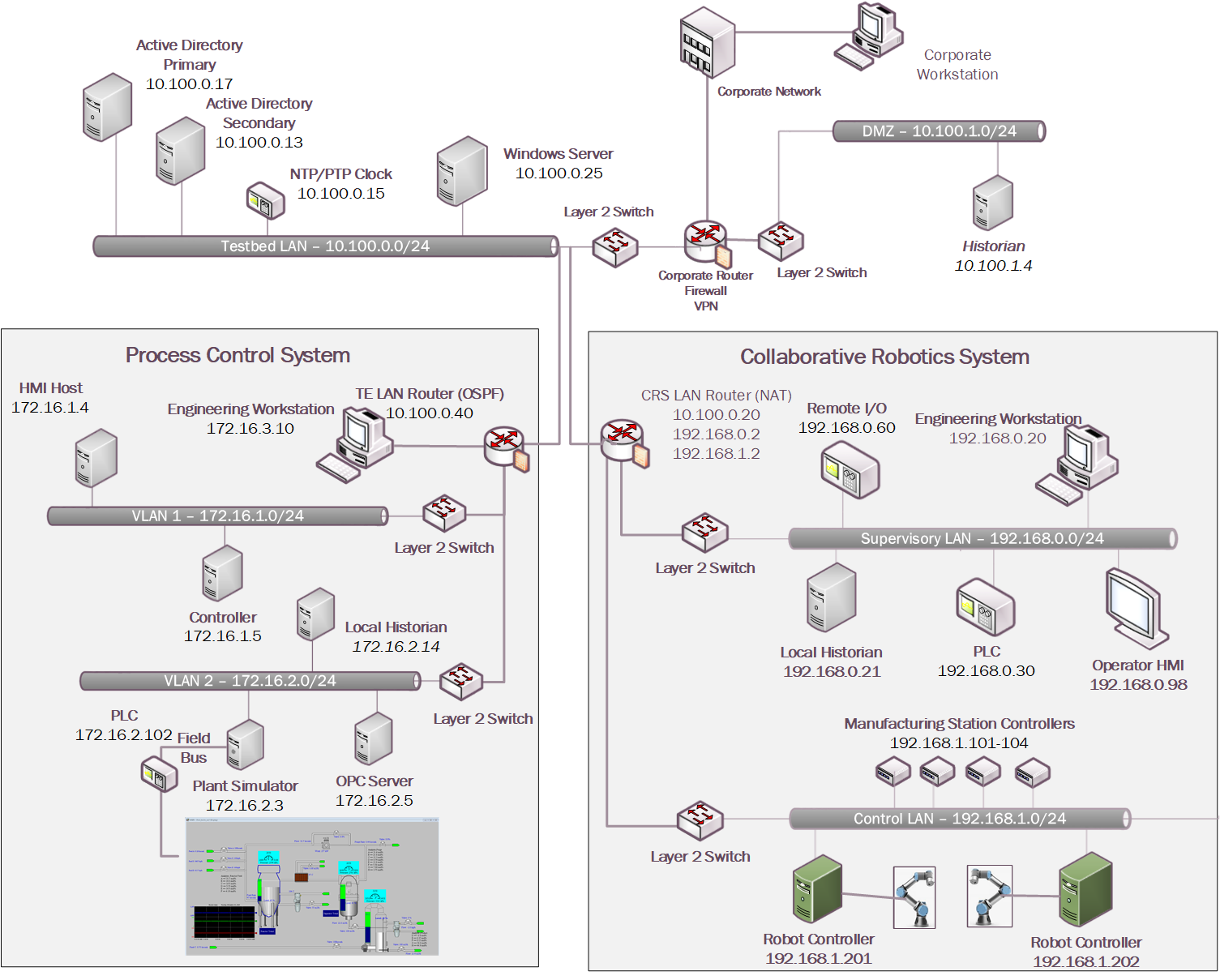
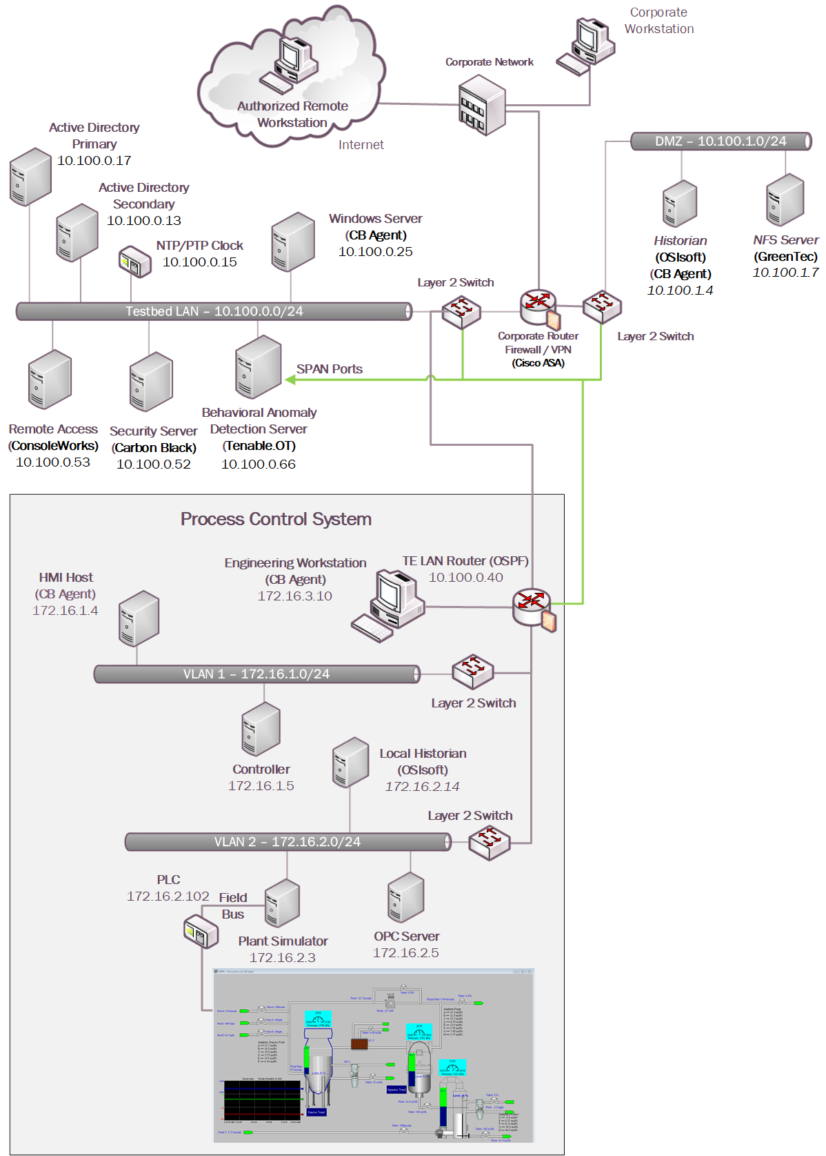
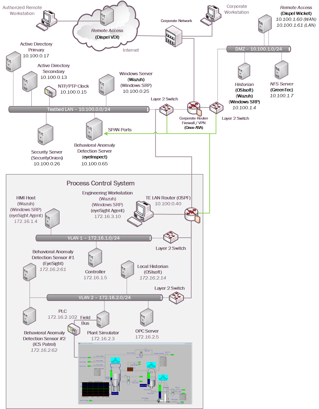
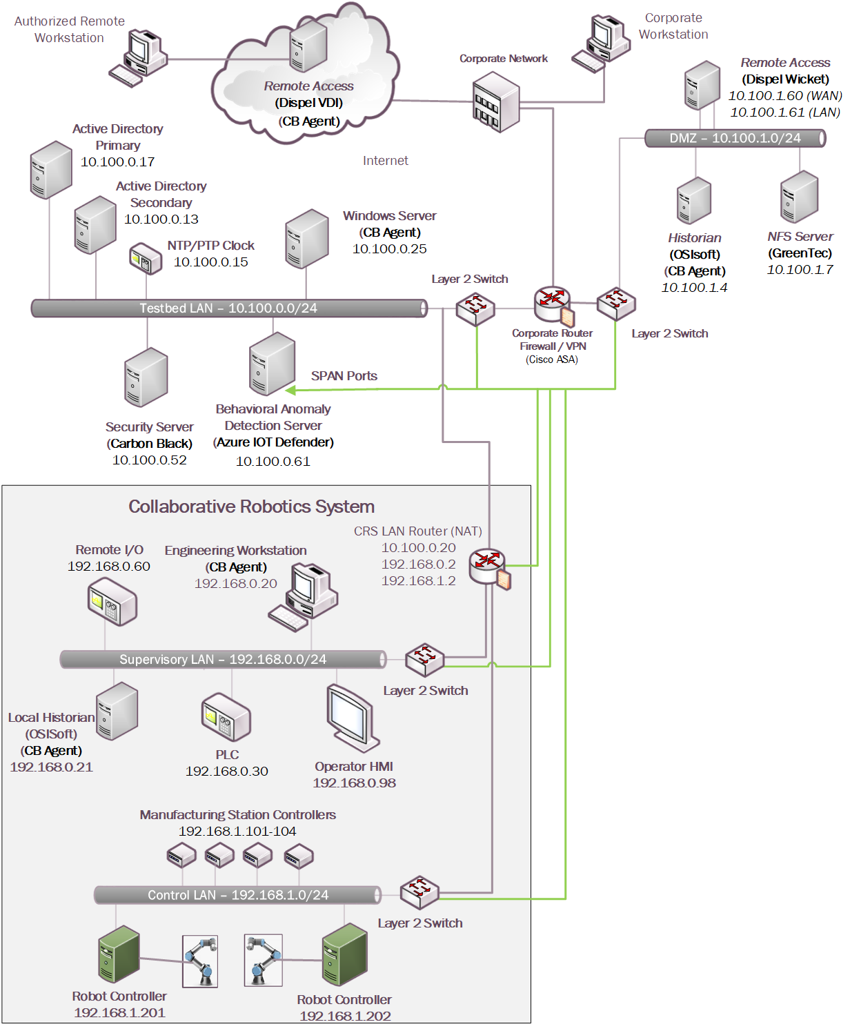
Figure 4‑1 depicts a high-level architecture for the demonstration environment consisting of a testbed local area network (LAN), a demilitarized zone (DMZ), the PCS, and the CRS. The environment utilizes a combination of physical and virtual systems and maintains a local network time protocol server for time synchronization. Additionally, the environment utilizes virtualized Active Directory servers for domain services. The tools used to support information and system integrity are deployed and integrated in the DMZ, Testbed LAN, PCS, and CRS according to vendor recommendations and standard practices as described in the detailed sections for each build.
Figure 4‑1: CSMS Network Architecture
4.3 Process Control System
A continuous manufacturing process is a type of manufacturing process that produces or processes materials continuously and in which the materials are continuously moving, going through chemical reactions, or undergoing mechanical or thermal treatment. Continuous manufacturing usually implies a 24-hours a day, seven days a week (24/7) operation with infrequent maintenance shutdowns. Examples of continuous manufacturing systems are chemical production, oil refining, natural gas processing, and wastewater treatment.
The PCS emulates the Tennessee-Eastman (TE) chemical reaction process. The TE problem, presented by Downs and Vogel [B15], is a well-known process-control problem in continuous chemical manufacturing. A control loop is required in the PCS to maintain a steady and stable chemical production. The PCS presents a real-world scenario in which a cybersecurity attack could represent a real risk to human safety, environmental safety, and economic viability. This allows the PCS to be used to assess the impact of cybersecurity attacks on the continuous process manufacturing environment.
The PCS includes a software simulator to emulate the TE chemical reaction process. The simulator is written in C code and is executed on a workstation-class computer. In addition, the system includes a series of COTS hardware, including an Allen-Bradley ControlLogix 5571 PLC, a software controller implemented in MATLAB for process control, a Rockwell FactoryTalk Human Machine Interface (HMI), an object linking and embedding for process control (OPC) data access (DA) server, a data historian, an engineering workstation, and several virtual LAN (VLAN) switches and network routers. Figure 4‑2 and Figure 4‑3 outline the process flow of the TE manufacturing process. The simulated TE process includes five major units with multiple input feeds, products, and byproducts that has 41 measured variables (sensors) and 12 manipulated variables (actuators). The PCS consists of a software simulated chemical manufacturing process (TE process), integrated with a series of COTS hardware, including PLCs, industrial network switches, protocol converters, and hardware modules to connect the simulated process and the control loop.
Figure 4‑2 Simplified Tennessee Eastman Process Model
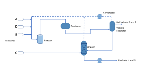
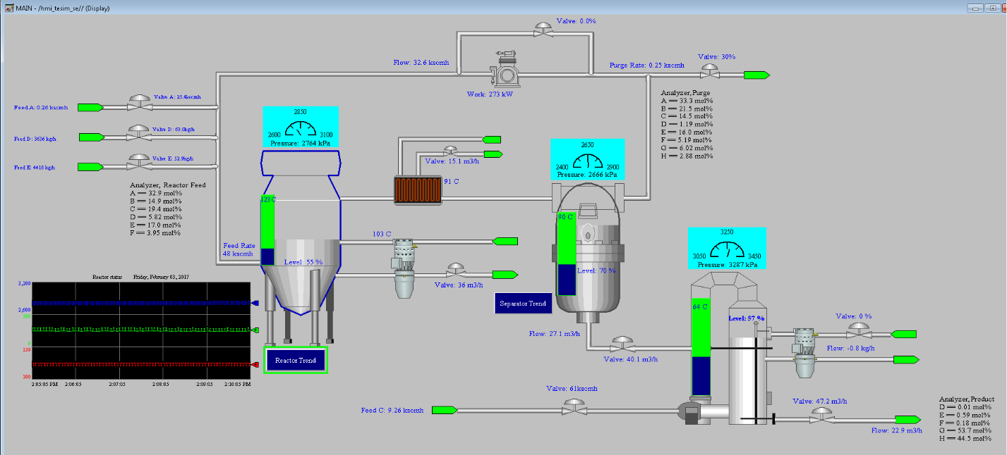
Figure 4‑3 HMI Screenshot for the PCS Showing the Main Components in the Process
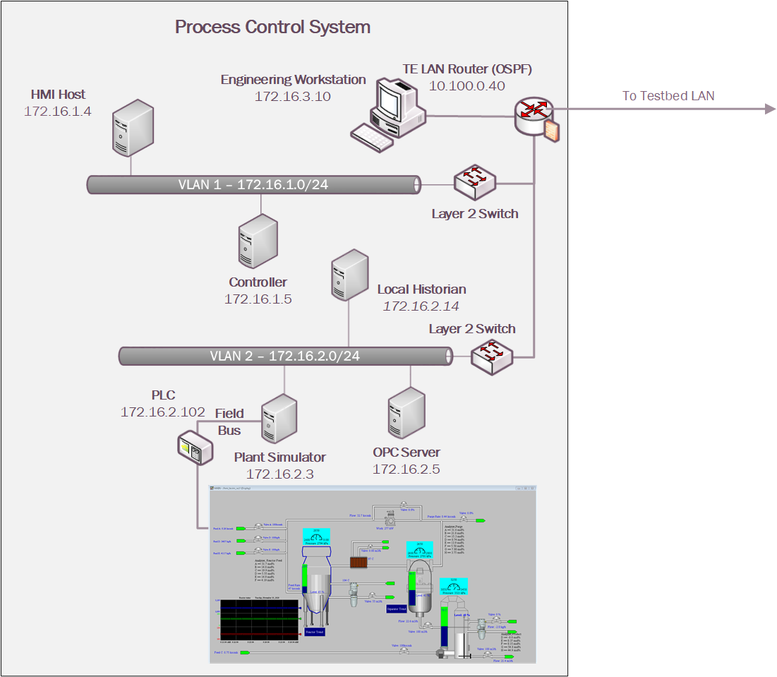
The PCS network architecture is shown in Figure 4‑4. The PCS network is connected to the Testbed LAN via a boundary router. The boundary router is an Allen-Bradley Stratix 8300. All network traffic is going through the boundary router to access the Testbed LAN and the DMZ. The PCS environment is segmented into three local networks, namely the engineering LAN, Operations LAN (VLAN1), and the Supervisory LAN (VLAN2). Each of these local networks is connected using an industrial network switch, an Allen-Bradley Stratix 5700. The engineering workstation is hosted in the engineering LAN. The HMI and the Plant Controller are hosted in the operations LAN. The Plant Simulator is hosted in the supervisory LAN along with the Local Historian, OPC Server, and the Supervisory PLC.
The Operations LAN (VLAN1) simulates a central control room environment. The supervisory LAN (VLAN2) simulates the process operation/ manufacturing environment, which typically consists of the operating plant, PLCs, OPC server, and data historian.
An OPC DA server is the main data gateway for the PLC and the simulated controller. The PLC reads in the manufacturing process sensor data from the Plant Simulator using the DeviceNet connection and communicates the data to the OPC DA server. The PLC also retrieves actuator information from the controller through the OPC DA and transmits to the Plant Simulator. The controller uses a MATLAB Simulink interface to communicate with the OPC DA server directly.
Figure 4‑4 PCS Network
4.4 Collaborative Robotics System (CRS)
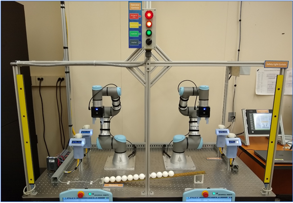
The CRS workcell, shown in Figure 4‑5, contains two robotic arms that perform a material handling process called machine tending [B8]. Robotic machine tending utilizes robots to interact with machinery, performing physical operations a human operator would normally perform (e.g., loading and unloading of parts in a machine, opening and closing machine doors, activating operator control panel buttons, etc.).
Parts are transported by two Universal Robots UR3e robotic arms through four simulated machining stations. Each station communicates with the Supervisory PLC (a Beckhoff CX9020) over the workcell network, which monitors and controls all aspects of the manufacturing process. An HMI (Red Lion G310) allows the workcell operator to monitor and control process parameters.
Figure 4‑5 The CRS Workcell
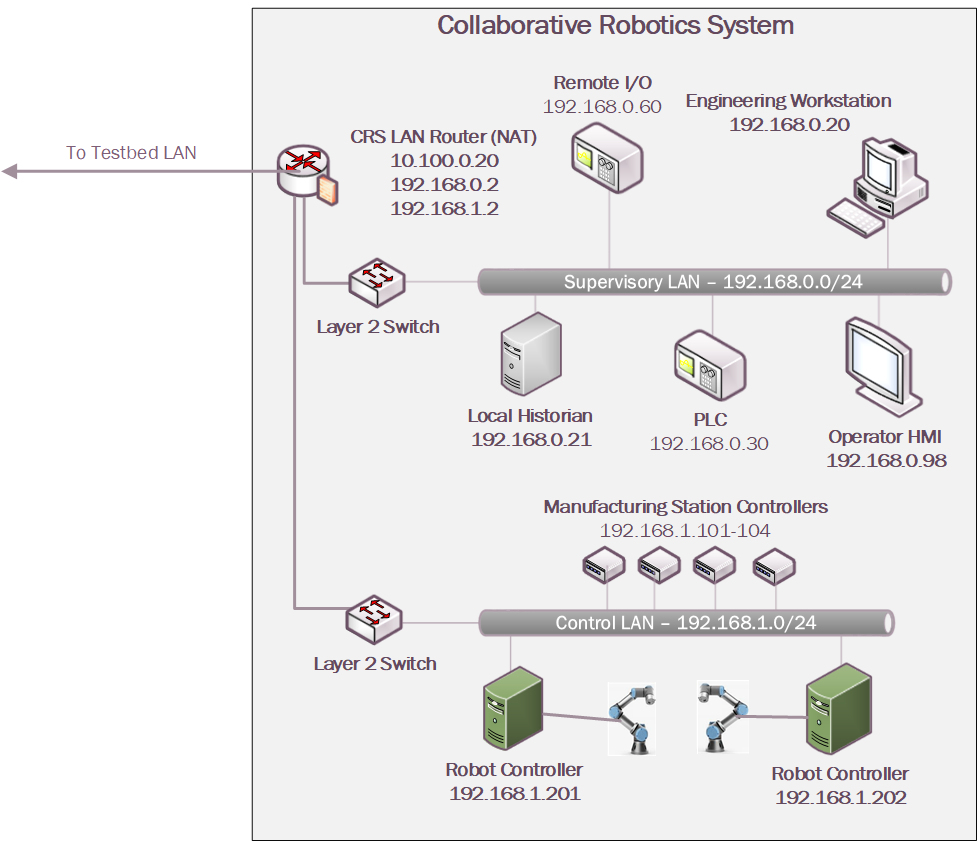
The CRS network, shown in Figure 4‑6, is hierarchically architected, separating the supervisory devices from the low-level OT that control the manufacturing process. The top-level router is a Siemens RUGGEDCOM RX1510, which provides firewall capabilities, logical access to the Testbed LAN network, network address translation (NAT), and other cybersecurity capabilities. The router is connected to the Testbed LAN (identified in Figure 4‑1 as the Testbed LAN) using NAT. Layer 2 network traffic for the Supervisory LAN is handled by a Netgear GS724T-managed Ethernet switch, and network traffic for the Control LAN is handled by a Siemens i800-managed Ethernet switch.
Figure 4‑6 CRS Network
4.5 Logical Network and Security Architectures
The following sections provide a high-level overview of the technology integration into the ICS environments for each solution, also referred to as a build. Additional details related to the installation and configuration of these tools are provided in Volume C of this guide.
4.5.1 Build 1
For Build 1, the technologies in Table 4‑2 were integrated into the PCS environment, Testbed LAN, and DMZ segments of the testbed environment to enhance system and information integrity capabilities.
Table 4‑2 Build 1 Technology Stack to Capabilities Map
Capability |
Products |
Description |
|---|---|---|
AAL |
Carbon Black |
Carbon Black Server is deployed within the Testbed LAN with the Carbon Black Agents installed on key workstations and servers in the Testbed LAN, PCS environment, and DMZ to control application execution. |
BAD, Hardware/Software/Firmware Modification Detection |
PI Server |
Deployed in the DMZ and PCS environments, the PI Server provides the historian repository for process data through its Data Archive and generates Event Frames upon detection of abnormal manufacturing system behavior. |
Tenable.ot |
Passively monitors the PCS network, Testbed LAN, and DMZ for abnormal network activity via SPAN ports, and is also configured to capture detailed asset information for supporting inventory, change via both passive and active scanning. |
|
File Integrity Checking |
Carbon Black |
Deployed within the Testbed LAN environment with the Carbon Black Agents installed on key workstations and servers to monitor the integrity of local files. |
ForceField, WORMdisk |
A GreenTec fileserver is added to the DMZ environment and configured with both a ForceField and WORM drive to provide a protected archive for the historian data and the approved versions of configuration, source (PLC Programs), and executable files for the ICS environment. |
|
User Authentication and Authorization |
ConsoleWorks |
Deployed to centralize the access and management of the systems and credentials. ConsoleWorks is deployed to the Testbed LAN to allow connections to the PCS environment. |
Remote Access |
AnyConnect |
Supports authenticated VPN connections to the environment with limited access to only the TDI ConsoleWorks web interface. |
The technology was integrated into the lab environment as shown in Figure 4‑7.
Figure 4‑7 Build 1, PCS Complete Architecture with Security Components
4.5.2 Build 2
For Build 2, the technologies in Table 4‑3 were integrated into the PCS, Testbed LAN, and DMZ segments of the testbed environment to enhance system and information integrity capabilities.
Table 4‑3 Build 2 Technology Stack to Capabilities Map
Capability |
Product |
Description |
|---|---|---|
AAL |
Windows SRP |
AD Group Policy Objects (GPOs) are used to configure and administer the Windows Software Restriction Policy (SRP) capabilities within the Testbed LAN environment and PCS environments. For non-domain systems (e.g., Dispel VDI and DMZ systems), the GPO was applied as local settings on the systems. |
BAD, Hardware/Software/Firmware Modification Detection |
PI Server |
Deployed in the DMZ and PCS environments, the PI Server provides the historian repository for process data through its Data Archive and generates Event Frames upon detection of abnormal manufacturing system behavior. |
eyeInspect ICSPatrol |
Passively monitors the PCS network, Testbed LAN, and DMZ for abnormal network activity via SPAN ports, and is also configured to capture detailed asset information for supporting inventory and change management capabilities using the ICSPatrol server, which can perform scans on ICS components. |
|
File Integrity Checking |
Wazuh |
The Security Onion server is used to manage and monitor the integrity of local files using the Wazuh agents deployed on the Dispel VDI, DMZ, Testbed LAN, and PCS. |
ForceField, WORMdisk |
A GreenTec fileserver is added to the DMZ environment and configured with both a ForceField and WORM drive to provide a protected archive for the historian data and the approved versions of configuration, source, and executable files for the ICS environment. |
|
User Authentication and Authorization |
Dispel |
The Dispel Wicket is deployed to the DMZ environment and integrated with the Dispel cloud-based environment to provide a virtual desktop interface (VDI) with a secure remote connection to the testbed environment. Through this connection, authorized users are permitted to access resources in both the Testbed LAN and PCS environment. |
Remote Access |
The technology was integrated into the lab environment as shown in Figure 4‑8.
Figure 4‑8 Build 2, PCS Complete Architecture with Security Components
4.5.3 Build 3
The technologies in Table 4‑4 were integrated into the CRS for Build 3 to enhance system and data integrity capabilities.
Table 4‑4 Build 3 Technology Stack to Capabilities Map
Capability |
Products |
Description |
|---|---|---|
AAL |
Windows SRP |
AD Group Policy Objects (GPOs) are used to configure and administer the Windows Software Restriction Policy (SRP) capabilities within the Testbed LAN environment and CRS environments. |
BAD, Hardware/Software/Firmware Modification Detection |
PI Server |
Deployed in the DMZ and CRS environments, the PI Server provides the historian repository for process data through its Data Archive and generates Event Frames upon detection of abnormal manufacturing system behavior |
Dragos |
Passively monitors the CRS network, Testbed LAN, and DMZ for abnormal network activity via SPAN ports and receives Event Frames from the DMZ PI system through the PI Web API interface. |
|
File Integrity Checking |
Wazuh |
The Security Onion server is used to manage and monitor the integrity of local files using the Wazuh agents deployed on the DMZ, Testbed LAN, and CRS. |
ForceField, WORMdisk |
A GreenTec fileserver is added to the DMZ environment and configured with both a ForceField and WORM drive to provide a protected archive for the historian data and the approved versions of configuration and coding files for the ICS environment. |
|
User Authentication and Authorization |
ConsoleWorks |
Deployed to centralize the access and management of the systems and credentials. ConsoleWorks is deployed to allow connections within the CRS environment. |
Remote Access |
AnyConnect |
Supports authenticated VPN connections to the environment with limited access to only the TDI ConsoleWorks web interface. |
The technology was integrated into the lab environment as shown in Figure 4‑9.
Figure 4‑9 Build 3, CRS Complete Architecture with Security Components
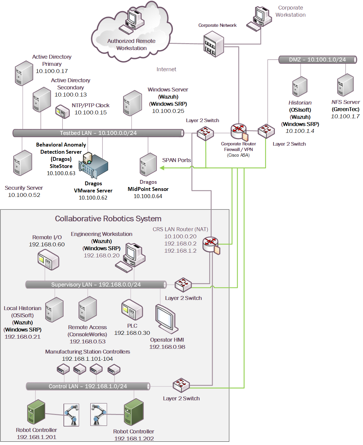
4.5.4 Build 4
For Build 4, the technologies in Table 4‑5 were integrated into the CRS, Testbed LAN, and DMZ segments of the testbed environment to enhance system and data integrity capabilities.
Table 4‑5 Build 4 Technology Stack to Capabilities Map
Capability |
Pro ducts |
Description |
|---|---|---|
AAL |
Carbon Black |
Deployed within the Testbed LAN environment with the Carbon Black agents installed on key workstations and servers to control application execution. |
BAD, Hardware/are/Software/Firmware Modification Detection |
PI Server |
Deployed in the DMZ and CRS environments, the PI Server provides the historian repository for process data through its Data Archive and generates Event Frames upon detection of abnormal manufacturing system behavior. |
Azure Defender for IoT |
Passively monitors the CRS network, Testbed LAN, and DMZ for abnormal network activity via SPAN ports and is also configured to capture detailed asset information for supporting inventory and change management capabilities. |
|
File Integrity Checking |
Carbon Black |
Deployed within the Testbed LAN environment with the Carbon Black agents installed on key workstations and servers to monitor the integrity of local files. |
ForceField, W ORMdisk |
A GreenTec fileserver is added to the DMZ environment and configured with both a ForceField and WORM drive to provide a protected archive for the historian data and the approved versions of configuration and coding files for the ICS environment. |
|
User Authentication and Authorization |
Dispel |
The Dispel Wicket is deployed to the DMZ environment and integrated with the Dispel cloud-based environment to provide a VDI with a secure remote connection to the testbed environment. Through this connection, authorized users are permitted to access resources in both the Testbed LAN and CRS environment. |
Remote Access |
The technology was integrated into the lab environment as shown in Figure 4‑10.
Figure 4‑10 Build 4, CRS Complete Architecture with Security Components
5 Security Characteristic Analysis
The purpose of the security characteristic analysis is to understand the extent to which the project meets its objective to demonstrate protecting information and system integrity in ICS environments. In addition, it seeks to understand the security benefits and drawbacks of the example solution.
5.1 Assumptions and Limitations
The security characteristic analysis has the following limitations:
It is neither a comprehensive test of all security components nor a red-team exercise.
It cannot identify all weaknesses.
It does not include the lab infrastructure.
5.2 Example Solution Testing
This section presents a summary of the solution testing and results. A total of eleven tests were developed for the builds. The following information is provided for each scenario:
Objective: Purpose of the scenario and what it will demonstrate
Description: Brief description of the scenario and the actions performed
Relevant NIST Cybersecurity Framework Subcategories: Mapping of NIST Cybersecurity Framework subcategories relevant to the scenario
Assumptions: Assumptions about the cyber-environment
Security Capabilities and Products: Capabilities and products demonstrated during the scenario
Test Procedures: Steps performed to execute the scenario
Expected Results: Expected results from each capability and product demonstrated during the scenario, and for each build
Actual Test Results: Confirm the expected results
Overall Result: Were the security capabilities and products able to meet the objective when the scenario was executed (PASS/FAIL rating).
Additional information for each scenario such as screenshots captured during the execution of the test procedures and detailed results from the security capabilities are presented in Appendix D.
5.2.1 Scenario 1: Protect Host from Malware Infection via USB
Objective |
This test demonstrates blocking the introduction of malware through physical access to a workstation within the manufacturing environment. |
Description |
An authorized user transports executable files into the manufacturing system via a USB flash drive that contains malware. |
Relevant NIST Cybersecurity Framework Subcategories |
PR.DS-6, PR.MA-2, DE.AE-2 |
Assumptions |
|
Security Capabilities and Products |
Build 1:
Build 2:
Build 3:
Build 4:
|
Test Procedures |
|
Expected Results |
|
Actual Test Results |
|
Overall Result |
PASS |
5.2.2 Scenario 2: Protect Host from Malware Infection via Network Vector
Objective |
This test demonstrates the detection of malware introduced from the network. |
Description |
An attacker pivoting from the corporate network into the manufacturing environment attempts to insert malware to establish persistence in the manufacturing environment. |
Relevant NIST Cybersecurity Framework Subcategories |
PR.DS-6, PR.MA-1, DE.AE-1, DE.AE-2, DE.AE-3, DE.CM-1, DE.CM-3, DE.CM-7 |
Assumptions |
|
Security Capabilities and Products |
Build 1:
Build 2:
Build 3:
Build 4:
|
Test Procedures |
|
Expected Results |
|
Actual Test Results |
|
Overall Result |
PASS |
5.2.3 Scenario 3: Protect Host from Malware via Remote Access Connections
Objective |
This test demonstrates blocking malware that is attempting to infect the manufacturing system through authorized remote access connections. |
Description |
A remote workstation authorized to use a remote access connection has been infected with malware. When the workstation is connected to the manufacturing environment through the remote access connection, the malware attempts to pivot and spread to vulnerable host(s). |
Relevant NIST Cybersecurity Framework Subcategories |
PR.AC-1, PR.AC-3, PR.AC-4, PR.AC-7, PR.MA-1, PR.MA-2, DE.CM-3, DE.CM-7 |
Assumptions |
|
Security Capabilities and Products |
Build 1:
Build 2:
Build 3:
Build 4:
|
Test Procedures |
|
Expected Results |
|
Actual Test Results |
|
Overall Result |
PASS |
5.2.4 Scenario 4: Protect Host from Unauthorized Application Installation
Objective |
This test demonstrates blocking installation and execution of unauthorized applications on a workstation in the manufacturing system. |
Description |
An authorized user copies downloaded software installation files from a shared network drive accessible from the workstation in the manufacturing system. The user then attempts to install the unauthorized software on the workstation. |
Relevant NIST Cybersecurity Framework Subcategories |
PR.DS-6, PR.MA-1, DE.AE-1, DE.AE-2, DE.AE-3, DE.CM-1, DE.CM-3, DE.CM-7 |
Assumptions |
|
Security Capabilities and Products |
Build 1:
Build 2:
Build 3:
Build 4:
|
Test Procedures |
|
Expected Results |
|
Actual Test Results |
|
Overall Result |
PASS |
5.2.5 Scenario 5: Protect from Unauthorized Addition of a Device
Objective |
This test demonstrates detection of an unauthorized device connecting to the manufacturing system. |
Description |
An individual authorized to access the physical premises connects and uses an unauthorized device on the manufacturing network. |
Relevant NIST Cybersecurity Framework Subcategories |
PR.DS-6, PR.MA-1, DE.AE-1, DE.AE-2, DE.AE-3, DE.CM-1, DE.CM-3, DE.CM-7 |
Assumptions |
|
Security Capabilities and Products |
Build 1:
Build 2:
Build 3:
Build 4:
|
Test Procedures |
|
Expected Results |
|
Actual Test Results |
|
Overall Result |
PASS |
5.2.6 Scenario 6: Detect Unauthorized Device-to-Device Communications
Objective |
This test demonstrates detection of unauthorized communications between devices. |
Description |
A device authorized to be on the network attempts to establish an unapproved connection. |
Relevant NIST Cybersecurity Framework Subcategories |
PR.DS-6, PR.MA-1, DE.AE-1, DE.AE-2, DE.AE-3, DE.CM-1, DE.CM-3, DE.CM-7 |
Assumptions |
|
Security Capabilities and Products |
Build 1:
Build 2:
Build 3:
Build 4:
|
Test Procedures |
|
Expected Results |
|
Actual Test Results |
|
Overall Result |
PASS |
5.2.7 Scenario 7: Protect from Unauthorized Deletion of Files
Objective |
This test demonstrates protection of files from unauthorized deletion both locally and on network file share. |
Description |
An authorized user attempts to delete files on an engineering workstation and a shared network drive within the manufacturing system. |
Relevant NIST Cybersecurity Framework Subcategories |
PR.DS-1, PR.DS-6, PR.IP-4, PR.MA-1, DE.AE-2 |
Assumptions |
|
Security Capabilities and Products |
Build 1:
Build 2:
Build 3:
Build 4:
|
Test Procedures |
|
Expected Results |
|
Actual Test Results |
|
Overall Result |
PASS |
5.2.8 Scenario 8: Detect Unauthorized Modification of PLC Logic
Objective |
This test demonstrates detection of PLC logic modification. |
Description |
An authorized user performs an unapproved or unauthorized modification of the PLC logic from an engineering workstation. |
Relevant NIST Cybersecurity Framework Subcategories |
PR.AC-3,PR.AC-7, PR.DS-6, PR.MA-1, PR.MA-2, DE.AE-1, DE.AE-2, DE.AE-3, DE.CM-1, DE.CM-3, DE.CM-7 |
Assumptions |
None |
Security Capabilities and Products |
Build 1:
Build 2:
Build 3:
Build 4:
|
Test Procedures |
|
Expected Results |
|
Actual Test Results |
|
Overall Result |
PASS |
5.2.9 Scenario 9: Protect from Modification of Historian Data
Objective |
This test demonstrates blocking of modification of historian archive data. |
Description |
An attacker coming from the corporate network pivots into the manufacturing environment and attempts to modify historian archive data. |
Relevant NIST Cybersecurity Framework Subcategories |
PR.DS-6, PR.MA-1, DE.AE-2 |
Assumptions |
|
Security Capabilities and Products |
Build 1:
Build 2:
Build 3:
Build 4:
|
Test Procedures |
|
Expected Results |
|
Actual Test Results |
|
Overall Result |
PASS |
5.2.9.1 Scenario 10: Detect Sensor Data Manipulation
Objective |
This test demonstrates detection of atypical data reported to the historian. |
Description |
A sensor in the manufacturing system begins sending atypical data values to the historian. |
Relevant NIST Cybersecurity Framework Subcategories |
PR.IP-4, PR.DS-6, PR.MA-1, DE.AE-1, DE.AE-2, DE.AE-3, DE.CM-1, DE.CM-3, DE.CM-7 |
Assumptions |
|
Security Capabilities and Products |
|
Test Procedures |
|
Expected Results |
|
Actual Test Results |
|
Overall Result |
PASS |
5.2.9.2 Scenario 11: Detect Unauthorized Firmware Modification
Objective |
This test demonstrates detection of device firmware modification. |
Description |
An authorized user performs a change of the firmware on a PLC. |
Relevant NIST Cybersecurity Framework Subcategories |
PR.DS-6, PR.MA-1, DE.AE-1, DE.AE-2, DE.AE-3, DE.CM-1, DE.CM-3, DE.CM-7 |
Assumptions |
None |
Security Capabilities and Products |
Build 1:
Build 2:
Build 3:
Build 4:
|
Test Procedures |
|
Expected Results |
|
Actual Test Results |
|
Overall Result |
PASS |
5.3 Scenarios and Findings
One aspect of our security evaluation involved assessing how well the reference design addresses the security characteristics that it was intended to support. The NIST Cybersecurity Framework Subcategories were used to provide structure to the security assessment by consulting the specific sections of each standard that are cited in reference to a Subcategory. The cited sections provide validation points that the example solution would be expected to exhibit. Using the NIST Cybersecurity Framework Subcategories as a basis for organizing our analysis allowed us to systematically consider how well the reference design supports the necessary security characteristics.
5.3.1 PR.AC-1: Identities and Credentials are Issued, Managed, Verified, Revoked, and Audited for Authorized Devices, Users, and Processes
This NIST Cybersecurity Framework Subcategory is supported through user authentication and user authorization capabilities in addition to the native credential management capabilities associated with the tools. In each of the systems, user accounts were issued, managed, verified, revoked, and audited.
5.3.2 PR.AC-3: Remote Access is Managed
This NIST Cybersecurity Framework Subcategory is supported by remote access tools integrated with the user authentication and authorization systems. Together, these tools provide a secure channel for an authorized user to access the manufacturing environment from a remote location. These tools are configurable to allow organizations to control who can remotely access the system, what the user can access, and when access is allowed by a user.
5.3.3 PR.AC-4: Access Permissions and Authorizations are Managed, Incorporating the Principles of Least Privilege and Separation of Duties
This NIST Cybersecurity Framework Subcategory is supported by the user authentication and user authorization capabilities. These tools are used to grant access rights to each user and notify if suspicious activity is detected. This includes granting access to maintenance personnel responsible for certain sub-systems or components of ICS environments while preventing them from accessing other sub-systems or components. Suspicious activities include operations attempted by an unauthorized user, restricted operations performed by an authenticated user who is not authorized to perform those operations, and operations that are performed outside of the designated time frame.
5.3.4 PR.AC-7: Users, Devices, and Other Assets are Authenticated (e.g., single-factor, multi-factor) Commensurate with the Risk of the Transaction (e.g., Individual Security and Privacy Risks and Other Organizational Risks)
This NIST Cybersecurity Framework Subcategory is supported through user authentication and user authorization capabilities in addition to the native credential management capabilities associated with the tools. Based on the lab’s risk assessment, the authentication and authorization systems used user passwords as one factor to verify identity and grant access to the environment. To bolster security in the environment, IP addresses were used as a secondary factor for remote access.
5.3.5 PR.DS-1: Data-at-Rest is Protected
This NIST Cybersecurity Framework Subcategory is supported using file integrity checking. For end points, the file integrity tools alert when changes to local files are detected. For historian backups and system program and configuration backups, data was stored on read only or write-once drives to prevent data manipulation.
5.3.6 PR.DS-6: Integrity Checking Mechanisms are Used to Verify Software, Firmware, and Information Integrity
This NIST Cybersecurity Framework Subcategory is supported through file integrity checking tools and the BAD tools. The file integrity checking tools monitor the information on the manufacturing end points for changes. The BAD tools monitor the environments for changes made to software, firmware, and validate sensor and actuator information.
5.3.7 PR.IP-4: Backups of Information are Conducted, Maintained, and Tested
This NIST Cybersecurity Framework Subcategory is supported by file integrity checking using secure storage to protect backup data. System configuration settings, PLC logic files, and historian databases all have backups stored on secure storage disks. The secure storage is constructed in a way that prohibits modifying or deleting data that is on the disk.
5.3.8 PR.MA-1: Maintenance and Repair of Organizational Assets are Performed and Logged, with Approved and Controlled Tools
This NIST Cybersecurity Framework Subcategory is supported by a combination of tools including AAL, the user authentication and user authorization tools, and the behavior anomaly detection tools. User authentication and user authorization tools provide a controlled environment for authorized users to interact with the manufacturing environment. Behavior anomaly detection tools provide a means to detect maintenance activities in the environment such as PLC logic modification or PLC firmware updates via the network. This information can be combined with data from a computerized maintenance management system to ensure that all maintenance activities are appropriately approved and logged. Also, AAL prevents unapproved software from running on systems to ensure that only approved tools are used for maintenance activities.
5.3.9 PR.MA-2: Remote Maintenance of Organizational Assets is Approved, Logged, and Performed in a Manner that Prevents Unauthorized Access
This NIST Cybersecurity Framework Subcategory is supported by the remote access capability integrated with the user authentication and user authorization system. The tools in the solution were used to grant access for performing remote maintenance on specific assets. The tools prevent unauthorized users from gaining access to the manufacturing environment.
5.3.10 DE.AE-1: A Baseline of Network Operations and Expected Data Flows for Users and Systems is Established and Managed
This NIST Cybersecurity Framework Subcategory is supported by behavior anomaly detection tools. Network baselines were established and approved based on an understanding of normal operations and data flows identified by the behavior anomaly detection tools.
5.3.11 DE.AE-2: Detected Events are Analyzed to Understand Attack Targets And Methods
This NIST Cybersecurity Framework Subcategory is supported by all the capabilities included in the solutions. Logs of suspicious activities from the tools can be used by security managers and engineers to understand what unusual activity has occurred in the manufacturing system. Analyzing these logs provides a mechanism to determine what systems were accessed and what actions may have been performed on them. Although not demonstrated in these solutions, an analytic engine would enhance the detection capability of the solution.
5.3.13 DE.CM-1: The Network is Monitored to Detect Potential Cybersecurity Events
This NIST Cybersecurity Framework Subcategory is supported by the BAD and remote access capabilities used in the example solutions to monitor the manufacturing network to detect potential cybersecurity events. The BAD tools monitor network communications at the external boundary of the system and at key internal points within the network, along with user activities and traffic patterns, and compare it to the established baseline. The remote access capabilities monitor the network communications at the external boundary of the system. This helps detect unauthorized local, network, and remote connections and identify unauthorized use of the manufacturing system.
5.3.14 DE.CM-3: Personnel Activity is Monitored to Detect Potential Cybersecurity Events
This NIST Cybersecurity Framework Subcategory is supported by the authentication and authorization tools that allow for monitoring personnel activity while connected through these tools. Further, AAL and file integrity checking tools provide the ability to monitor user actions on hosts. Additionally, BAD tools monitor and record events associated with personnel actions traversing network traffic. Each tool provides a different perspective in monitoring personnel activity within the environment. The resulting alerts and logs from these tools can be monitored individually or collectively to support investigations for potential malicious or unauthorized activity within the environment.
5.3.15 DE.CM-7: Monitoring for Unauthorized Personnel, Connections, Devices, and Software is Performed
This NIST Cybersecurity Framework Subcategory is supported by BAD, AAL, user authentication and user authorization, and remote access capabilities of the solutions. The BAD tools established an information baseline for approved assets and connections. Then the manufacturing network is monitored using the BAD capability for any deviation by the assets and connections from the established baseline. If any deviation is detected, an alert is generated. Additionally, the AAL tool blocks any unauthorized application installation or execution and generates an alert on these events. User authentication and user authorization tools monitor for unauthorized personnel connecting to the environment. Remote access capabilities monitor for unauthorized connections to the environment.
6 Future Build Considerations
This guide has presented technical solutions for maintaining and monitoring system and information integrity, which will help detect and prevent incidents in a manufacturing environment. Future builds should demonstrate methods and techniques for fusing event and log data from multiple platforms into a security operations center to improve monitoring and detection capabilities for an organization. Future builds should also demonstrate how to recover from a loss of system or information integrity such as a ransomware attack for ICS environments.
Additionally, trends in manufacturing such as Industry 4.0 and the industrial IoT are increasing connectivity, increasing the attack surface, and increasing the potential for vulnerabilities. Future builds should consider how these advances can be securely integrated into manufacturing environments.