NIST SPECIAL PUBLICATION 1800-30B
Securing Telehealth Remote Patient Monitoring Ecosystem
Volume B:
Approach, Architecture, and Security Characteristics
Jennifer Cawthra*
Nakia Grayson
Ronald Pulivarti
National Cybersecurity Center of Excellence
National Institute of Standards and Technology
Bronwyn Hodges
Jason Kuruvilla*
Kevin Littlefield
Julie Snyder
Sue Wang
Ryan Williams*
Kangmin Zheng
The MITRE Corporation
McLean, Virginia
*Former employee; all work for this publication done while at employer.
February 2022
FINAL
This publication is available free of charge from https://doi.org/10.6028/NIST.SP.1800-30
The second draft of this publication is available free of charge from https://www.nccoe.nist.gov/sites/default/files/legacy-files/rpm-nist-sp1800-30-2nd-draft.pdf

DISCLAIMER
Certain commercial entities, equipment, products, or materials may be identified by name or company logo or other insignia in order to acknowledge their participation in this collaboration or to describe an experimental procedure or concept adequately. Such identification is not intended to imply special status or relationship with NIST or recommendation or endorsement by NIST or NCCoE; neither is it intended to imply that the entities, equipment, products, or materials are necessarily the best available for the purpose.
National Institute of Standards and Technology Special Publication 1800-30B, Natl. Inst. Stand. Technol. Spec. Publ. 1800-30B, 202 pages, (February 2022), CODEN: NSPUE2
FEEDBACK
As a private-public partnership, we are always seeking feedback on our practice guides. We are particularly interested in seeing how businesses apply NCCoE reference designs in the real world. If you have implemented the reference design, or have questions about applying it in your environment, please email us at hit_nccoe@nist.gov.
All comments are subject to release under the Freedom of Information Act.
NATIONAL CYBERSECURITY CENTER OF EXCELLENCE
The National Cybersecurity Center of Excellence (NCCoE), a part of the National Institute of Standards and Technology (NIST), is a collaborative hub where industry organizations, government agencies, and academic institutions work together to address businesses’ most pressing cybersecurity issues. This public-private partnership enables the creation of practical cybersecurity solutions for specific industries, as well as for broad, cross-sector technology challenges. Through consortia under Cooperative Research and Development Agreements (CRADAs), including technology partners—from Fortune 50 market leaders to smaller companies specializing in information technology security—the NCCoE applies standards and best practices to develop modular, adaptable example cybersecurity solutions using commercially available technology. The NCCoE documents these example solutions in the NIST Special Publication 1800 series, which maps capabilities to the NIST Cybersecurity Framework and details the steps needed for another entity to re-create the example solution. The NCCoE was established in 2012 by NIST in partnership with the State of Maryland and Montgomery County, Maryland.
NIST CYBERSECURITY PRACTICE GUIDES
NIST Cybersecurity Practice Guides (Special Publication 1800 series) target specific cybersecurity challenges in the public and private sectors. They are practical, user-friendly guides that facilitate the adoption of standards-based approaches to cybersecurity. They show members of the information security community how to implement example solutions that help them align with relevant standards and best practices and provide users with the lists of materials, configuration files, and other information they need to implement a similar approach.
The documents in this series describe example implementations of cybersecurity practices that businesses and other organizations may voluntarily adopt. These documents do not describe regulations or mandatory practices nor do they carry statutory authority.
ABSTRACT
Increasingly, healthcare delivery organizations (HDOs) are relying on telehealth and remote patient monitoring (RPM) capabilities to treat patients at home. RPM is convenient and cost-effective, and its adoption rate has increased. However, without adequate privacy and cybersecurity measures, unauthorized individuals may expose sensitive data or disrupt patient monitoring services.
RPM solutions engage multiple actors as participants in patients’ clinical care. These actors include HDOs, telehealth platform providers, and the patients themselves. Each participant uses, manages, and maintains different technology components within an interconnected ecosystem, and each is responsible for safeguarding their piece against unique threats and risks associated with RPM technologies.
This practice guide assumes that the HDO engages with a telehealth platform provider that is a separate entity from the HDO and patient. The telehealth platform provider manages a distinct infrastructure, applications, and set of services. The telehealth platform provider coordinates with the HDO to provision, configure, and deploy the RPM components to the patient home and assures secure communication between the patient and clinician.
The NCCoE analyzed RPM ecosystem risk factors by applying methods described in the NIST Risk Management Framework. The NCCoE also leveraged the NIST Cybersecurity Framework, NIST Privacy Framework, and other relevant standards to identify measures to safeguard the ecosystem. In collaboration with healthcare, technology, and telehealth partners, the NCCoE built an RPM ecosystem in a laboratory environment to explore methods to improve the cybersecurity of an RPM.
Technology solutions alone may not be sufficient to maintain privacy and security controls on external environments. This practice guide notes the application of people, process, and technology as necessary to implement a holistic risk mitigation strategy.
This practice guide’s benefits include helping organizations assure the confidentiality, integrity, and availability of an RPM solution, enhancing patient privacy and limiting HDO risk when implementing an RPM solution.
KEYWORDS
access control; authentication; authorization; behavioral analytics; cloud storage; data privacy; data security; encryption; HDO; healthcare; healthcare delivery organization; remote patient monitoring; RPM; telehealth; zero trust
ACKNOWLEDGMENTS
We are grateful to the following individuals for their generous contributions of expertise and time.
Name |
Organization |
|---|---|
Alex Mohseni |
Accuhealth |
Stephen Samson |
Accuhealth |
Brian Butler |
Cisco |
Matthew Hyatt |
Cisco |
Kevin McFadden |
Cisco |
Peter Romness |
Cisco |
Brad Hoehn |
Huntington Ingalls Industries-Mission Driven Innovative Solutions (HII-MDIS) |
David Lemire |
Huntington Ingalls Industries-Mission Driven Innovative Solutions (HII-MDIS) |
Steven Dean |
Inova Health System |
Zach Furness |
Inova Health System |
James Carder |
LogRhythm |
Brian Coulson |
LogRhythm |
Steven Forsyth |
LogRhythm |
Jake Haldeman |
LogRhythm |
Andrew Hollister |
LogRhythm |
Zack Hollister |
LogRhythm |
Dan Kaiser |
LogRhythm |
Sally Vincent |
LogRhythm |
Vidya Murthy |
MedCrypt |
Axel Wirth |
MedCrypt |
Stephanie Domas |
MedSec |
Garrett Sipple |
MedSec |
Nancy Correll |
The MITRE Corporation |
Spike Dog |
The MITRE Corporation |
Robin Drake |
The MITRE Corporation |
Sallie Edwards |
The MITRE Corporation |
Donald Faatz |
The MITRE Corporation |
Nedu Irrechukwu |
The MITRE Corporation |
Karri Meldorf |
The MITRE Corporation |
Stuart Shapiro |
The MITRE Corporation |
Barbara Cuthill |
NIST |
Jeffrey Marron |
NIST |
Paul Watrobski |
NIST |
John Dwyier |
Onclave Networks, Inc. (Onclave) |
Chris Grodzickyj |
Onclave |
Marianne Meins |
Onclave |
Dennis Perry |
Onclave |
Christina Phillips |
Onclave |
Robert Schwendinger |
Onclave |
James Taylor |
Onclave |
Chris Jensen |
Tenable |
Joshua Moll |
Tenable |
Jeremiah Stallcup |
Tenable |
Rebecca Herold |
The Privacy Professor Consultancy |
Julio C. Cespedes |
The University of Mississippi Medical Center |
Saurabh Chandra |
The University of Mississippi Medical Center |
Donald Clark |
The University of Mississippi Medical Center |
Alan Jones |
The University of Mississippi Medical Center |
Kristy Simms |
The University of Mississippi Medical Center |
Richard Summers |
The University of Mississippi Medical Center |
Steve Waite |
The University of Mississippi Medical Center |
Dele Atunrase |
Vivify Health |
Aaron Gatz |
Vivify Health |
Michael Hawkins |
Vivify Health |
Robin Hill |
Vivify Health |
Dennis Leonard |
Vivify Health |
David Norman |
Vivify Health |
Bill Paschall |
Vivify Health |
Eric Rock |
Vivify Health |
Alan Stryker |
Vivify Health |
Dave Sutherland |
Vivify Health |
Michael Tayler |
Vivify Health |
The Technology Partners/Collaborators who participated in this build submitted their capabilities in response to a notice in the Federal Register. Respondents with relevant capabilities or product components were invited to sign a Cooperative Research and Development Agreement (CRADA) with NIST, allowing them to participate in a consortium to build this example solution. We worked with:
Technology Partner/Collaborator |
Build Involvement |
|---|---|
Accuhealth Evelyn |
|
Cisco Firepower Version 6.3.0 Cisco Umbrella Cisco Stealthwatch Version 7.0.0 |
|
subject matter expertise |
|
LogRhythm XDR Version 7.4.9 LogRhythm NetworkXDR Version 4.0.2 |
|
subject matter expertise |
|
subject matter expertise |
|
Onclave Zero Trust Platform Version 1.1.0 |
|
Tenable.sc Vulnerability Management Version 5.13.0 with Nessus |
|
subject matter expertise |
|
Vivify Pathways Home Vivify Pathways Care Team Portal |
DOCUMENT CONVENTIONS
The terms “shall” and “shall not” indicate requirements to be followed strictly to conform to the publication and from which no deviation is permitted. The terms “should” and “should not” indicate that among several possibilities, one is recommended as particularly suitable without mentioning or excluding others, or that a certain course of action is preferred but not necessarily required, or that (in the negative form) a certain possibility or course of action is discouraged but not prohibited. The terms “may” and “need not” indicate a course of action permissible within the limits of the publication. The terms “can” and “cannot” indicate a possibility and capability, whether material, physical, or causal.
PATENT DISCLOSURE NOTICE
NOTICE: The Information Technology Laboratory (ITL) has requested that holders of patent claims whose use may be required for compliance with the guidance or requirements of this publication disclose such patent claims to ITL. However, holders of patents are not obligated to respond to ITL calls for patents and ITL has not undertaken a patent search in order to identify which, if any, patents may apply to this publication.
As of the date of publication and following call(s) for the identification of patent claims whose use may be required for compliance with the guidance or requirements of this publication, no such patent claims have been identified to ITL.
No representation is made or implied by ITL that licenses are not required to avoid patent infringement in the use of this publication.
List of Figures
Figure 4‑2 Architecture Layers
Figure 4‑3 RPM Communications Paths
Figure 4‑4 RPM Dataflow Option 1
Figure 4‑5 RPM Dataflow Option 2
Figure 4‑6 Network Segmentation and VLAN Within the RPM Lab
Figure C-1 Risk Management Framework
Figure D-1 Privacy View of RPM Solution Dataflow
Figure F-1 Enclave Gateway Model
List of Tables
Table 3‑2 Problematic Data Action Taxonomy
Table 3‑3 Cybersecurity Risk Taxonomy
Table 3‑4 Privacy Risk Taxonomy
Table 3‑5 Security Characteristics and Controls Mapping–NIST Cybersecurity Framework
Table 3‑6 Privacy Characteristics and Controls Mapping–NIST Privacy Framework
Table 3‑7 Products and Technologies
Table 6‑1 Functional Evaluation Requirements
Table C-1 Information Types and Categorizations
Table C-2 Assessment Scale: Likelihood of Threat Event Initiation
Table C-3 Threats Applied to the Patient Home
Table C-4 Threats Applied to the Telehealth Platform Provider
Table C-5 Threats Applied to the HDO
Table C-6 Taxonomy of Threat Sources
Table C-7 RPM Functions and Processes
Table C-8 Vulnerability Taxonomy
Table C-9 Components in the Patient Home Environment
Table C-10 Biometric Device Subcomponent Breakdown
Table C-11 Interface Device Subcomponent Breakdown
Table C-12 Laptop Subcomponent Breakdown
Table C-13 Desktop Subcomponent Breakdown
Table C-14 Threat Event to Adverse Action Mapping
1 Summary¶
This practice guide demonstrates how healthcare delivery organizations (HDOs) can implement cybersecurity and privacy controls to enhance the resiliency of telehealth services. In collaboration with industry partners, the National Cybersecurity Center of Excellence (NCCoE) at the National Institute of Standards and Technology (NIST) built a laboratory environment to simulate the telehealth ecosystem and enable remote patient monitoring (RPM) services for patients.
RPM is convenient, cost-effective, and growing, but it comes with security and privacy risks. Patient monitoring systems are often found in controlled healthcare facility environments. RPM is different in that monitoring equipment is deployed in the patient’s home, which may not offer the same level of cybersecurity or physical security control to prevent misuse or compromise. Without privacy or cybersecurity controls in place within the RPM ecosystem, patient data and the ability to communicate with the care providers may be compromised.
This practice guide explores a situation in which a care provider prescribes deploying an RPM device to the patient home. The RPM device captures biometric data on regular intervals, conveys the data to the clinical care team, and allows patient-clinician communication without the patient making an in-person visit to the HDO. RPM enables care based on the patient’s needs, regardless of geographic constraints.
Capturing biometric data at regular intervals allows clinicians to have broader insight into a patient’s condition. With larger data sets, clinicians can monitor the patient’s condition and make diagnosis and treatment decisions with more robust information. RPM solutions allow audio and video communication in addition to utilizing biometric data, and they support the patient-clinician relationship.
Implementing an RPM ecosystem involves multiple parties and environments. In developing the reference architecture for this practice guide, the NCCoE considered components that would be deployed in three distinct domains that encompass the RPM ecosystem: the patient home environment, the telehealth platform provider, and the HDO. The project team engaged with a telehealth platform provider that leveraged cloud services and facilitated audio- and videoconferencing between the patient home and the HDO. The telehealth platform provider provisioned and managed biometric devices that were deployed in the patient home, and routed data and communication between the patient home and the HDO.
The NCCoE built a laboratory environment to simulate the telehealth ecosystem, performed a risk assessment, and developed an example implementation that demonstrates how HDOs can use standards-based, commercially available cybersecurity technologies and collaborate with telehealth platform providers to assure privacy and security biometric devices that are deployed to the patient home.
For ease of use, the following paragraphs provide a short description of each section of this volume.
Section 1, Summary, presents: the challenge addressed by the NCCoE project with an in-depth look at our approach, the architecture, and the security characteristics we used; the solution demonstrated to address the challenge; benefits of the solution; and the collaborators who participated in building, demonstrating, and documenting the solution.
Section 2, How to Use This Guide, explains how business decision makers, program managers, information technology (IT) professionals (e.g., systems administrators), and biometric engineers might use each volume of the guide.
Section 3, Approach, offers a detailed treatment of the scope of the project, the risk assessment that informed platform development, and the technologies and components that industry collaborators gave us to enable platform development.
Section 4, Architecture, specifies the components within the RPM ecosystem from business, security, and infrastructure perspectives and details how data and processes flow throughout the ecosystem. This section also describes the security capabilities and controls referenced in the NIST Cybersecurity Framework through tools provided by the project collaborators.
Section 5, Security and Privacy Characteristic Analysis, provides details about the tools and techniques used to perform risk assessments pertaining to RPM.
Section 6, Functional Evaluation, summarizes the test sequences employed to demonstrate security platform services, the NIST Cybersecurity Framework Functions to which each test sequence is relevant, and the NIST Special Publication (SP) 800-53 Revision 5 controls demonstrated in the example implementation.
Section 7, Future Build Considerations, is a brief treatment of other applications that NIST might explore in the future to further protect a telehealth environment.
The appendices provide acronym translations, references, a deeper dive into the threats and risks associated with RPM, the review of the NIST Privacy Risk Assessment Methodology (PRAM), and a list of additional informative security references cited in the framework.
1.1 Challenge¶
Telehealth RPM solutions deploy components across multiple infrastructure domains that are maintained uniquely. When HDOs deploy RPM solutions, those solutions implement architectures that distribute components across the HDO, telehealth platform providers, and patient homes. Each of these respective environments is managed by different groups of people, often with different sets of resources and technical capabilities. Risks are distributed across the solution architecture, and the methods by which one may mitigate those risks vary in complexity. While HDOs do not have the ability to manage and deploy privacy and cybersecurity controls unilaterally, they retain the responsibility to ensure that appropriate controls and risk mitigation are applied.
This practice guide can help your organization: |
|---|
|
1.2 Solution¶
Technology solutions alone may not be sufficient to maintain privacy and security controls on external environments. This practice guide notes the involvement of people, process, and technology as necessary to implement a holistic risk mitigation strategy. When developing this practice guide, the NCCoE team applied risk assessment approaches to determine where risks may occur and used assessment processes to identify applicable controls.
The NCCoE collaborated with healthcare, technology, and telehealth partners to build a distributed RPM solution. The RPM solution implemented controls that safeguard the HDO environment and documented approaches that the telehealth platform provider addresses. Telehealth platform providers assure that RPM components are isolated within the patient home environment. The telehealth platform provider assures end-to-end data security between the patient and the HDO.
2 How to Use This Guide¶
This NIST Cybersecurity Practice Guide demonstrates a standards-based reference design and provides users with the information they need to replicate an RPM environment. This reference design is modular and can be deployed in whole or in part.
This guide contains three volumes:
NIST SP 1800-30A: Executive Summary
NIST SP 1800-30B: Approach, Architecture, and Security Characteristics–what we built and why (you are here)
NIST SP 1800-30C: How-To Guides–instructions for building the example solution
Depending on your role in your organization, you might use this guide in different ways:
Business decision makers, including chief security and technology officers, will be interested in the Executive Summary, NIST SP 1800-30A, which describes the following topics:
challenges that enterprises face in securing the RPM ecosystem
example solution built at the NCCoE
benefits of adopting the example solution
Technology or security program managers who are concerned with how to identify, understand, assess, and mitigate risk will be interested in this part of the guide, NIST SP 1800-30B, which describes what we did and why. The following sections will be of particular interest:
Section 3.4, Risk Assessment, provides a description of the risk analysis we performed
Section 3.5, Security Control Map, maps the security characteristics of this example solution to cybersecurity standards and best practices
You might share the Executive Summary, NIST SP 1800-30A, with your leadership team members to help them understand the importance of adopting standards-based commercially available technologies that can help secure the RPM ecosystem.
IT professionals who want to implement an approach like this will find the whole practice guide useful. You can use the how-to portion of the guide, NIST SP 1800-30C:, to replicate all or parts of the build created in our lab. The how-to portion of the guide provides specific product installation, configuration, and integration instructions for implementing the example solution. We do not re-create the product manufacturers’ documentation, which is generally widely available. Rather, we show how we incorporated the products together in our environment to create an example solution.
This guide assumes that IT professionals have experience implementing security products within the enterprise. While we have used a suite of commercial products to address this challenge, this guide does not endorse these particular products. Your organization can adopt this solution or one that adheres to these guidelines in whole, or you can use this guide as a starting point for tailoring and implementing parts of the NCCoE’s risk assessment and deployment of a defense-in-depth strategy in a distributed RPM solution. Your organization’s security experts should identify the products that will best integrate with your existing tools and IT system infrastructure. We hope that you will seek products that are congruent with applicable standards and best practices. Section 3.6, Technologies, lists the products we used and maps them to the cybersecurity controls provided by this reference solution.
A NIST Cybersecurity Practice Guide does not describe “the” solution but a possible solution. Comments, suggestions, and success stories will improve subsequent versions of this guide. Please contribute your thoughts to hit_nccoe@nist.gov.
Acronyms used in figures are in the List of Acronyms appendix.
2.1 Typographic Conventions¶
The following table presents typographic conventions used in this volume.
Typeface/ Symbol |
Meaning |
Example |
|---|---|---|
Italics |
file names and path names; references to documents that are not hyperlinks; new terms; and placeholders |
For language use and style guidance, see the NCCoE Style Guide. |
Bold |
names of menus, options, command buttons, and fields |
Choose File > Edit. |
Monospace |
command-line input, onscreen computer output, sample code examples, and status codes |
|
Monospace (block) |
multi-line input, on-screen computer output, sample code examples, status codes |
% mkdir -v nccoe_projects
mkdir: created directory 'nccoe_projects'
|
blue text |
link to other parts of the document, a web URL, or an email address |
All publications from NIST’s NCCoE are available at https://www.nccoe.nist.gov. |
3 Approach¶
RPM is a telehealth use case wherein healthcare providers can use internet-based technologies to track biometric data from the patient’s home. Patients may have chronic or recurring health conditions that require regular clinical monitoring; however, in-person visitation may be impractical or undesirable. Technology enables capturing biometric and patient-generated data, having those data relayed to systems that clinicians may use to evaluate a patient, and bidirectional communication of the data between the patient and clinician. RPM may be an appropriate means for performing healthcare in pandemic scenarios or to address patients who may live in parts of the country where healthcare settings or practitioners are scarce.
The NCCoE collaborated with a healthcare Community of Interest (COI) that included technology and cybersecurity vendors, healthcare cybersecurity subject matter experts, and healthcare systems to identify RPM use cases, data workflows, ecosystem actor, and general deployment architecture. Further, with the assistance of the COI and external cybersecurity subject matter experts, a risk assessment was performed and reviewed, thereby confirming the measures and outcomes that were determined from the risk assessment activity.
Additionally, this project reviewed NIST SP 800-171 Rev. 2, Protecting Controlled Unclassified Information in Nonfederal Systems and Organizations [B1], as well as NIST SP 800-181 Rev. 1, Workforce Framework for Cybersecurity (NICE Framework) [B2], for further guidance. These documents serve as background for this project, with primary emphasis on the NIST Cybersecurity Framework [B3], the NIST Risk Management Framework [B4], and the NIST Privacy Framework [B5].
3.1 Audience¶
This guide is intended for professionals implementing an RPM ecosystem for HDOs that use third-party telehealth platform providers. This guide examines scenarios where HDOs partner with a third-party telehealth platform provider where that telehealth platform provider manages devices that are used by the patient in their home setting. The telehealth platform provider implements technology that collects and makes biometric data available to clinicians, thus allowing the HDO to focus on patient care delivery. Approaches and controls focus on securing end-to-end communications and safeguarding assets and data that reside at HDO facilities; and they also discuss measures that HDOs and telehealth platform providers should implement in the patient home.
3.2 Scope¶
This RPM practice guide focuses on scenarios where patients with chronic or recurring conditions have biometric devices in their home that enable clinicians to regularly receive biometric data. The scope of this practice guide is limited to remote patient monitoring and does not include remote care. Patients and clinicians may use audio- and videoconferencing. The solution includes a third-party telehealth platform provider that provisions and manages biometric devices and provides means of communication.
3.3 Assumptions¶
This practice guide makes the following assumptions:
RPM architecture includes deploying components to three distinct domains: the patient home, the telehealth platform provider, and the HDO.
HDOs are regulated entities and must comply with federal, state, and local laws and regulations. In complying with laws and regulations, HDOs have implemented adequate privacy and security programs that include activities to address risk to both the organization and individuals when deploying an RPM architecture. Controls that have been implemented in accordance with laws and regulations provide an enterprise scope that this document refers to as pervasive controls.
The telehealth platform provider maintains an adequate privacy and security control environment.
The telehealth platform provider manages the configuration of patient home-deployed equipment.
The patient home may have different communications options such as cellular data connectivity or broadband internet.
RPM solutions emphasize collaboration. An RPM program’s efficacy depends on the patient, the telehealth platform provider, and the HDO to participate in the program and apply adequate privacy and security practices. The HDO does not define the control environments for the telehealth platform provider or the patient home. Each participant needs sufficient awareness and exercises appropriate control over components that operate in their domain.
Patient engagement activities provide the patient a clear understanding of privacy practices and expectations that address the specifics of the RPM architecture.
For this practice guide, telehealth platform providers deployed biometric devices with cellular data capabilities. Additionally, this practice guide implemented a solution for biometric devices that used patient home Wi-Fi communications.
3.4 Risk Assessment¶
NIST SP 800-30 Revision 1, Guide for Conducting Risk Assessments, states that risk is “a measure of the extent to which an entity is threatened by a potential circumstance or event, and typically a function of: (i) the adverse impacts that would arise if the circumstance or event occurs; and (ii) the likelihood of occurrence”. The guide further defines risk assessment as “the process of identifying, estimating, and prioritizing risks to organizational operations (including mission, functions, image, reputation), organizational assets, individuals, other organizations, and the Nation, resulting from the operation of an information system. Part of risk management incorporates threat and vulnerability analyses, and considers mitigations provided by security controls planned or in place”.
The NCCoE recommends that any discussion of risk management, particularly at the enterprise level, begins with a comprehensive review of NIST SP 800-37 Revision 2, Risk Management Framework for Information Systems and Organizations.
The Risk Management Framework (RMF) guidance, as a whole, proved to be invaluable in giving us a baseline to assess risks, from which we developed the project, the security characteristics of the build, and this guide.
In this practice guide, the NCCoE implements multiple approaches in assessing risk. An RPM environment is composed of multiple domains, with different constituents managing each domain. When analyzing risk, this practice guide contextualizes that risk and selects mitigating controls by disrupting threats. A description of how this practice guide addresses these concepts is in Appendix C, Threats and Risks. The risk assessments included in Appendix C represent how the practice guide examines risks. Organizations may find that the threats, vulnerabilities, and risks that they observe may differ from this practice guide’s assessment. The risk assessments in this practice guide serve as examples that may catalyze how organizations perform their own risk assessments.
3.4.1 Threats¶
NIST SP 800-30 Revision 1 defines a threat as “[a]ny circumstance or event with the potential to adversely impact organizational operations and assets, individuals, other organizations, or the Nation through an information system via unauthorized access, destruction, disclosure, or modification of information, and/or denial of service”. Threats are actions that may compromise a system’s confidentiality, integrity, or availability [B6]. Table 3‑1 describes threats that have been evaluated for this project. Threats evolve, and an organization needs to perform its own analysis when evaluating threats and risks that the organization faces.
Table 3‑1 below is a sample threat taxonomy as it applies across the entire RPM ecosystem. The threat taxonomy uses: a confidentiality (C), integrity (I), and availability (A) categorization; the threat event considered; and a description of the threat event. While the threat taxonomy provides a landscape view of threats, organizations may want to perform threat modeling to determine contextual application of threats. Appendix C, Threats and Risks, describes concepts on how to examine contextualized threats.
Table 3‑1 Threat Taxonomy
C, I, A |
Threat Event |
Description |
|---|---|---|
C |
phishing |
Phishing attacks are a form of social engineering, where the attacker presents themselves as a trusted party to gain the confidence of the victim. |
I, A |
malicious software |
Malicious software (malware) is unauthorized code that may be introduced to a system. It performs unintended actions that may disrupt normal system function. Malware may masquerade as desirable apps or applications. |
I, A |
command and control |
Command and control attacks may begin with deployment of malware. Malware may allow a system to be operated remotely by unauthorized entities. Should a system fall victim to a command-and-control attack, that system may then be used as a pivot point to attack other components, either within the organization’s infrastructure or as a point where attacks may be launched against other organizations. |
A |
ransomware |
Ransomware is a form of malware that disrupts access to system resources. A typical form of ransomware involves the malware employing encryption that disables a legitimate system user from accessing files. Ransomware attacks generally involve a demand for payment to restore files. Payment does not ensure that the attacker will decrypt files, however. |
C |
credential escalation |
Credential escalation attacks seek to take user account capabilities and extend those to a privileged level of capability. |
I, A |
operating system or application disruption |
The operating system or application may be adversely affected by malicious actors who successfully implement malware on the target device. Data may be altered or the device or application may not function properly. |
C |
data exfiltration |
Malicious actors may be able to retrieve sensitive information from vulnerable devices. Malware may be used for this purpose. |
A |
denial of service attack |
Flooding network connections with high-volume traffic to disrupt communication in patient home, between home and telehealth platform, or between telehealth platform provider and HDO. This type of attack could also be used to damage a device, e.g., through accelerated battery depletion. |
I |
transmitted data manipulation |
Unauthorized individuals may intercept and alter data transmissions. |
3.4.2 Vulnerabilities¶
This practice guide uses a customized application for identifying vulnerabilities, which aggregates vulnerabilities identified in NIST SP 800-30 Revision 1. As noted in this special publication, a vulnerability is a deficiency or weakness that a threat source may exploit, resulting in a threat event. The document further describes how vulnerabilities may exist in a broader context, i.e., that they may be found in organizational governance structures, external relationships, and mission/business processes. The table in Section C-6 of Appendix C, Threats and Risks, enumerates those vulnerabilities by using a holistic approach and represents those vulnerabilities that this project identified and for which it offers guidance.
3.4.3 Problematic Data Actions for Privacy¶
This build considered operational activities of the example solution that interact with patient data during RPM processes (“data actions”) and identified those that potentially cause problems to individuals.
The NIST Privacy Framework defines a problematic data action as “a data action that could cause an adverse effect for individuals” [B5]. Problematic data actions can result in privacy risk to individuals and prevent an organization from developing a solution that meets the privacy engineering objectives of:
predictability: enabling reliable assumptions by individuals, owners, and operators about data and their processing by a system, product, or service
manageability: providing the capability for granular administration of data, including alteration, deletion, and selective disclosure
disassociability: enabling the processing of data or events without association to individuals or devices beyond the operational requirements of the system
Table 3‑2 below demonstrates the problematic data action taxonomy identified for the entire RPM ecosystem. This Problematic Data Action Taxonomy uses: a predictability (P), manageability (M), and disassociability (D) designation; the problematic data action considered; and the description of the problematic data action. While the Problematic Data Action Taxonomy provides a landscape view of problematic data action, an organization may want to perform a risk assessment to determine contextual application of the problematic data action. The discussion about problematic data actions and risks in Appendix D introduces the PRAM [B7] and provides a more detailed analysis.
Table 3‑2 Problematic Data Action Taxonomy
P, M, D |
Problematic Data Action |
Description |
|---|---|---|
P, M |
distortion |
Inaccurate or misleadingly incomplete data are used or disseminated. Distortion can present users in an inaccurate, unflattering, or disparaging manner, opening the door for stigmatization, discrimination, or loss of liberty. |
M |
insecurity |
Lapses in data security can result in various problems, including loss of trust, exposure to economic loss and other identity theft-related harms, and dignity losses. |
D, M |
re-identification |
De-identified data, or data otherwise disassociated from specific individuals, become identifiable or associated with specific individuals again. It can lead to problems such as discrimination, loss of trust, and dignity losses. |
P, M |
unanticipated revelation |
Data reveal or expose an individual or facets of an individual in unexpected ways. Unanticipated revelation can arise from aggregation and analysis of large and/or diverse data sets. Unanticipated revelation can give rise to dignity losses, discrimination, and loss of trust and autonomy. |
The project team used the NIST PRAM [B7] and accompanying Catalog of Problematic Data Actions and Problems [B8] to conduct this analysis. Table 3‑2, Problematic Data Action Taxonomy, provides the results of this analysis. See Appendix D for additional considerations regarding examples of problematic data actions for RPM solutions.
3.4.4 Risk¶
As noted in Section 3.4, NIST SP 800-30 Revision 1, Guide for Conducting Risk Assessments, defines risk as “a measure of the extent to which an entity is threatened by potential circumstance or event, and is typically a function of: (i) the adverse impacts that would arise if the circumstance or event occurs; and (ii) the likelihood of occurrence” [B9].
Risk is the adverse impact; that is, risk is the result when a threat (attack) successfully leverages one or more vulnerabilities. As organizations consider risk, they should note that risk is not discrete; that is, one may realize multiple risks based on a successful attack. Notwithstanding, we consider those risks identified below. In reviewing these risks, please note that we consider unique scenarios that presume certain attack types for the two risks categorized as availability risks, those being ransomware and pivot point attacks.
Table 3‑3, Cybersecurity Risk Taxonomy, describes high-level cybersecurity risks that affect the RPM environment. The risk taxonomy table captures key risks, assigning where the risk may impact the organization across a confidentiality, integrity, and availability (CIA) [B6] dimension.
Table 3‑3 Cybersecurity Risk Taxonomy
C,I,A |
Risk |
Description |
Risk Level |
|---|---|---|---|
C |
fraudulent use of health-related information |
Health-related information may be used for several different fraudulent means, such as identity theft, insurance fraud, or extortion. |
medium |
I |
patient diagnoses disrupted based on timeliness interruption, leading to patient safety concerns |
Unavailability or significant delay in delivering biometric data may negate the benefits of remote patient monitoring. Clinicians may not be able to provide appropriate care should biometric data transmission be disrupted. |
medium |
I |
incorrect patient diagnosis due to change of data |
A critical patient event is missed due to changes in the data stream between device and HDO. |
high |
A |
process disruption due to ransomware |
Ransomware may prevent normal device operations. Data may be irretrievable and, therefore, may prevent clinical care. |
high |
I, A |
systemic disruption due to component compromise |
Disruptions to the system that affect its availability or integrity may compromise the benefits derived from remote patient monitoring. |
high |
I |
clinician misdiagnosis |
If data are altered inappropriately, clinicians may make inaccurate diagnoses, resulting in patient safety issues. |
high |
Table 3‑4, Privacy Risk Taxonomy, describes high-level privacy risks that affect the RPM environment. Table 3‑4 captures key risks, assigning where the risk may impact individuals, in the areas of predictability, manageability, and disassociability [B5]. Privacy risk levels to individuals depend on the context of specific RPM solution deployment and are not included. These risks are discussed further in Appendix D.
Table 3‑4 Privacy Risk Taxonomy
P, M, D |
Risk |
Description |
|---|---|---|
M |
Storage and movement of data create multiple points of potential exposure after data are collected from the patient. |
Insecurity: Storage and movement of data create multiple points of potential exposure after they are collected from the patient. RPM context: Biometric data and patient health information flow through various entities in the RPM solution, each of which plays a role in protecting the information. |
P, M |
Biometric device types can indicate patient health problems that individuals would prefer not to disclose beyond their healthcare provider. |
Unanticipated revelation: Biometric device types can indicate patient health problems that individuals would prefer not to disclose beyond their healthcare provider. RPM context: Using one or more biometric devices can indicate—to others beyond the patient’s healthcare provider—potential health problems for which a patient is being monitored. |
P, M |
Incorrect data capture of readings by devices may impact quality of patient care. |
Distortion: Device misuse may cause a failure to monitor patients in accordance with their healthcare plan. RPM context: Incorrect or unintended use of biometric devices may introduce data quality issues into the RPM environment, resulting in inaccurate or incomplete data being used to make decisions regarding patient care. |
D, M |
Aggregated data may expose patient information. |
Re-identification: Associating biometric data with patient identifiers can expose health conditions. RPM context: Associating biometric data in a way that exposes information about the patient could cause issues such as embarrassment and discrimination. Disassociated processing is intentionally used during some dataflows within the RPM solution to mitigate the risk of exposing identifiable patient information to vendors, administrators, and other practitioners who are outside the patient’s care team. |
P, M |
Exposure of patient information through multiple providers of system components increases the likelihood of exposure of patient data to unintended recipients. |
Unanticipated Revelation: Data processing is handled by multiple parties within the background of the ecosystem and is transparent to the patient. RPM context: Patient health information may be revealed in ways or to parties that the individual may not expect. Additionally, using one or more biometric devices can indicate potential health problems—to others beyond the patient’s healthcare provider—for which a patient is being monitored. |
3.4.5 Mitigating Risk¶
As noted above, risk is the adverse outcome when a threat successfully leverages a vulnerability. Mitigating risk may take many different forms. This practice guide addresses risk by performing a threat modeling exercise and by mitigating threats. The previous sections discussed threat from a holistic perspective. That is, the noted threats enumerate a broad survey of attack types that may adversely affect the RPM ecosystem. RPM decomposes to the following three distinct domains: patient home, telehealth platform provider, and HDO. As organizations consider measures to disrupt threats and adverse actions made against the ecosystem, an opportunity exists where organizations examine threats to identify controls that mitigate adverse actions identified by threat modeling.
3.5 Security Control Map¶
As this practice guide considered RPM ecosystem risks, the team performed a mapping to the NIST Cybersecurity Framework [B3]. This mapping established an initial set of appropriate control Functions, Categories, and Subcategories. The mapping demonstrated how selected Cybersecurity Framework Subcategories map to controls in NIST SP 800-53 Revision 5 [B10] as well as to the Workforce Framework for Cybersecurity (NICE Framework), NIST SP 800-181 [B2]. The table also lists sector-specific standards and best practices (e.g., the International Electrotechnical Commission [IEC] Technical Reports [TR], International Organization for Standardization [ISO]) as well as from the Health Insurance Portability and Accountability Act (HIPAA) [B11], [B12], [B13]). The security control map, shown in Table 3‑5, identifies a set of controls, including those specifically implemented in the lab build, as well as the pervasive set of controls as described in Section 5.2, Pervasive Controls, that HDOs should deploy. Practitioners should refer to Appendix C of NIST SP 1800-24, Securing Picture Archiving and Communication System (PACS) for further description of pervasive controls [B14].
Table 3‑5 Security Characteristics and Controls Mapping–NIST Cybersecurity Framework
NIST Cybersecurity Framework v1.1 |
NIST NICE Framework (NIST SP 800-181) |
NIST Sector-Specific Standards and Best Practices |
|||||
Function |
Category |
Subcategory |
NIST SP 800-53 Revision 5 |
IEC TR 80001-2-2 |
HIPAA Security Rule |
ISO/IEC 27001 |
|
IDENTIFY (ID) |
Asset Management (ID.AM) |
ID.AM-1: Physical devices and systems within the organization are inventoried |
CM-8
PM-5
|
N/A |
45 C.F.R. §§
164.308(a)(1)(ii)(A)
164.308(a)(4)(ii)(A)
164.308(a)(7)(ii)(E)
164.308(b)
164.310(d)
164.310(d)(2)(iii)
|
A.8.1.1
A.8.1.2
|
|
ID.AM-2: Software platforms and applications within the organization are inventoried. |
CM-8
|
45 C.F.R. §§
164.308(a)(1)(ii)(A)
164.308(a)(7)(ii)(E)
|
A.8.1.1
A.8.1.2
A.12.5.1
|
||||
ID.AM-4: External information systems are catalogued |
AC-20
PM-5
SA-9
|
45 C.F.R. §§
164.308(a)(4)(ii)(A)
164.308(b)
164.314(a)(1)
164.314(a)(2)(i)(B)
164.314(a)(2)(ii)
164.316(b)(2)
|
A.11.2.6
|
||||
ID.AM-5: Resources (e.g., hardware, devices, data, time, personnel, and software) are prioritized based on their classification, criticality, and business value |
CP-2
RA-2
RA-9
SA-20
SC-6
|
CO-OPL-001
|
SGUD |
45 C.F.R. §§
164.308(a)(7)(ii)(E)
|
A.8.2.1
|
||
Risk Assessment (ID.RA) |
ID.RA-1: Asset vulnerabilities are identified and documented |
CA-2
CA-5
CA-7
CA-8
PM-4
PM-15
RA-3
RA-5
SA-5
SA-11
SI-2
SA-4
SI-5
|
AN-ASA-001
AN-ASA-002
AN-TWA-001
CO-CLO-002
CO-OPS-001
SP-ARC-001
|
MLDP RDMP SGUD |
45 C.F.R. §§
164.308(a)(1)(i)
164.308(a)(1)(ii)(A)
164.308(a)(1)(ii)(B)
164.308(a)(7)(ii)(E)
164.308(a)(8)
164.310(a)(1)
|
A.12.6.1
A.18.2.3
|
|
ID.RA-4: Potential business impacts and likelihoods are identified |
CP-2
PM-9
PM-11
RA-2
RA-3
RA-9
|
AN-ASA-001
AN-ASA-002
AN-EXP-001
AN-LNG-001
AN-TGT-001
AN-TGT-002
AN-TWA-001
CO-CLO-001
CO-CLO-002
CO-OPL-001
CO-OPL-002
|
DTBK SGUD |
45 C.F.R. §§
164.308(a)(1)(i)
164.308(a)(1)(ii)(A)
164.308(a)(1)(ii)(B)
164.308(a)(6)
164.308(a)(7)(ii)(E)
164.308(a)(8)
|
A.16.1.6
Clause
6.1.2
|
||
ID.RA-5: Threats, vulnerabilities, likelihoods, and impacts are used to determine risk |
CA-2
CA-7
PM-16
PM-28
RA-2
RA-3
|
SP-SYS-001
|
SGUD |
45 C.F.R. §§
164.308(a)(1)(ii)(A)
164.308(a)(1)(ii)(B)
164.308(a)(1)(ii)(D)
164.308(a)(7)(ii)(D)
164.308(a)(7)(ii)(E)
164.316(a)
|
A.12.6.1 |
||
ID.RA-6: Risk responses are identified and prioritized |
CA-5
PM-4
PM-9
PM-28
RA-7
|
SP-SYS-001
|
DTBK SGUD |
45 C.F.R. §§
164.308(a)(1)(ii)(B)
164.314(a)(2)(i)(C)
164.314(b)(2)(iv)
|
Clause
6.1.3
|
||
PROTECT (PR) |
Identity Management, Authentication and Access Control (PR.AC) |
PR.AC-1: Identities and credentials are issued, managed, verified, revoked, and audited for authorized devices, users and processes |
IA-1
IA-2
IA-3
IA-4
IA-5
IA-7
IA-8
IA-9
IA-10
IA-11
IA-12
|
OM-ADM-001
|
ALOF AUTH EMRG NAUT PAUT |
45 C.F.R. §§
164.308(a)(3)(ii)(B)
164.308(a)(3)(ii)(C)
164.308(a)(4)(i)
164.308(a)(4)(ii)(B)
164.308(a)(4)(ii)(C)
164.312(a)(2)(i)
|
A.9.2.1
A.9.2.2
A.9.2.3
A.9.2.4
A.9.2.6
A.9.3.1
A.9.4.2
A.9.4.3
|
PR.AC-2: Physical access to assets is managed and protected |
PE-1
PE-2
PE-3
PE-4
PE-5
PE-6
PE-8
PE-9
|
OM-ADM-001
|
PLOK TXCF TXIG |
45 C.F.R. §§
164.308(a)(1)(ii)(B)
164.308(a)(7)(i)
164.308(a)(7)(ii)(A)
164.310(a)(1)
164.310(a)(2)(i)
164.310(a)(2)(ii)
|
A.11.1.1
A.11.1.2
A.11.1.3
A.11.1.4
A.11.1.5
A.11.1.6
A.11.2.1
A.11.2.3
A.11.2.5
A.11.2.6
A.11.2.7
A.11.2.8
|
||
PR.AC: Remote access is managed |
AC-1
AC-17
AC-19
AC-20
SC-15
|
OM-ADM-001
|
ALOF AUTH CSUP EMRG NAUT PAUT |
45 C.F.R. §§
164.308(a)(4)(i)
164.308(b)(1)
164.308(b)(3)
164.310(b)
164.312(e)(1)
164.312(e)(2)(ii)
|
A.6.2.1
A.6.2.2
A.11.2.6
A.13.1.1
A.13.2.1
|
||
PR.AC-4: Access permissions and authorizations are managed, incorporating the principles of least privilege and separation of duties |
AC-1
AC-2
AC-3
AC-5
AC-6
AC-14
AC-16
AC-24
|
OM-ADM-001
OM-KMG-001
PR-INF-001
|
ALOF AUTH CNFS EMRG NAUT PAUT |
45 C.F.R. §§
164.308(a)(3)
164.308(a)(4)
164.310(a)(2)(iii)
164.310(b)
164.312(a)(1)
164.312(a)(2)(i)
|
A.6.1.2
A.9.1.2
A.9.2.3
A.9.4.1
A.9.4.4
A.9.4.5
|
||
PR.AC-5: Network integrity is protected (e.g., network segregation, network segmentation) |
AC-4
AC-10
SC-7
SC-10
SC-20
|
MLDP NAUT |
45 C.F.R. §§
164.308(a)(4)(ii)(B)
164.310(a)(1)
164.310(b)
164.312(a)(1)
164.312(b)
164.312(c)
|
A.13.1.1
A.13.1.3
A.13.2.1
A.14.1.2
A.14.1.3
|
|||
PR.AC-6: Identities are proofed and bound to credentials and asserted in interactions |
AC-16
IA-1
IA-2
IA-4
IA-5
IA-8
IA-12
PE-2
PS-3
|
SP-RSK-002
OV-PMA-003
|
AUTH CNFS EMRG NAUT PLOK SGUD |
N/A |
A.7.1.1
A.9.1.2
|
||
PR.AC-7: Users, devices and other assets are authenticated (e.g., single-factor, multi-factor) commensurate with the risk of the interaction (e.g., individuals’ security and privacy risks and other organizational risks) |
AC-14
IA-1
IA-2
IA-3
IA-5
IA-8
IA-9
IA-10
IA-11
|
ALOF AUTH NAUT PAUT |
A.9.2.1
A.9.2.4
A.9.3.1
A.9.4.2
A.9.4.3
A.18.1.4
|
||||
Data Security (PR.DS) |
PR.DS-1: data-at-rest is protected |
MP-2
MP-3
MP-4
MP-5
MP-6
MP-7
MP-8
SC-28
|
IGAU MLDP NAUT SAHD STCF TXCF |
45 C.F.R. §§
164.308(a)(1)(ii)(D)
164.308(b)(1)
164.310(d)
164.312(a)(1)
164.312(a)(2)(iii)
164.312(a)(2)(iv)
|
A.8.2.3
|
||
PR.DS-2: Data-in-transit is protected |
SC-8
SC-11
|
OM-DTA-002
PR-CDA-001
|
IGAU NAUT STCF TXCF TXIG |
45 C.F.R. §§
164.308(b)(1)
164.308(b)(2)
164.312(e)(1)
164.312(e)(2)(i)
164.312(e)(2)(ii)
164.314(b)(2)(i)
|
A.8.2.3
A.13.1.1
A.13.2.1
A.13.2.3
A.14.1.2
A.14.1.3
|
||
PR.DS-3: Assets are formally managed throughout removal, transfers, and disposition |
CM-8
MP-6
PE-16
PE-20
|
N/A |
45 C.F.R. §§
164.308(a)(1)(ii)(A)
164.310(a)(2)(ii)
164.310(a)(2)(iii)
164.310(a)(2)(iv)
164.310(d)(1)
164.310(d)(2)
|
A.8.2.3
A.8.3.1
A.8.3.2
A.8.3.3
A.11.2.5
A.11.2.7
|
|||
PR.DS-4: Adequate capacity to ensure availability is maintained |
AU-4
CP-2
PE-11
SC-5
|
AUDT DTBK |
45 C.F.R. §§
164.308(a)(1)(ii)(A)
164.308(a)(1)(ii)(B)
164.308(a)(7)
164.310(a)(2)(i)
164.310(d)(2)(iv)
164.312(a)(2)(ii)
|
A.12.1.3
A.17.2.1
|
|||
PR-DS.5: Protections against data leaks are implemented |
AC-4
AC-5
AC-6
AU-13
PE-19
PS-6
SC-7
SI-4
|
SP-SYS-001
|
AUTH IGAU MLDP PLOK STCF TXCF TXIG |
45 C.F.R. §§
164.308(a)(1)(ii)(D)
164.308(a)(3)
164.308(a)(4)
164.310(b)
164.310(c)
164.312(a)
|
A.6.1.2
A.7.1.1
A.7.1.2
A.7.3.1
A.8.2.2
A.8.2.3
A.9.1.1
A.9.1.2
A.9.2.3
A.9.4.1
A.9.4.4
A.9.4.5
A.10.1.1
A.11.1.4
A.11.1.5
A.11.2.1
A.13.1.1
A.13.1.3
A.13.2.1
A.13.2.3
A.13.2.4
A.14.1.2
A.14.1.3
|
||
PR.DS-6: Integrity checking mechanisms are used to verify software, firmware, and information integrity |
SI-7
SI-10
|
IGUA MLDP |
45 C.F.R. §§
164.308(a)(1)(ii)(D)
164.312(b)
164.312(c)(1)
164.312(c)(2)
164.312(e)(2)(i)
|
A.12.2.1
A.12.5.1
A.14.1.2
A.14.1.3
A.14.2.4
|
|||
Information Protection (PR.IP) |
PR.IP-4: Backups of information are conducted, maintained, and tested |
CP-4
CP-6
CP-9
|
DTBK PLOK |
164.308(a)(7)(ii)(A)
164.308(a)(7)(ii)(B)
164.308(a)(7)(ii)(D)
164.310(a)(2)(i)
164.310(d)(2)(iv)
|
A.12.3.1
A.1.1.2
A.17.1.3
A.18.1.3
|
||
PR.IP-6: Data is destroyed according to policy |
MP-6
SR-12
|
DIDT |
45 C.F.R. §§
164.310(d)(2)(i)
164.310(d)(2)(ii)
|
A.8.2.3
A.8.3.1
A.8.3.2
A.11.2.7
|
|||
PR.IP-9: Response plans (Incident Response and Business Continuity) and recovery plans (Incident Recovery and Disaster Recovery) are in place and managed |
CP-1
CP-2
CP-7
CP-10
IR-1
IR-7
IR-8
IR-9
|
DTBK SGUD |
45 C.F.R. §§
164.308(a)(6)
164.308(a)(6)(i)
164.308(a)(7)
164.310(a)(2)(i)
164.312(a)(2)(ii)
|
A.16.1.1
A.17.1.1
A.17.1.2
A.17.1.3
|
|||
PR.IP-10: Response and recovery plans are tested |
CP-4
IR-3
PM-14
|
OM-NET-001
|
DTBK SGUD |
45 C.F.R. §§
164.308(a)(7)(ii)(D)
|
A.17.1.3
|
||
PR.IP-12: A Vulnerability management plan is developed and implemented |
RA-1
RA-3
RA-5
SI-2
|
OV-PMA-001
|
MLDP |
45 C.F.R. §§
164.308(a)(1)(i)
164.308(a)(1)(ii)(A)
164.308(a)(1)(ii)(A)
|
A.12.6.1
A.14.2.3
A.16.1.3
A.18.2.2
A.18.2.3
|
||
Maintenance (PR.MA) |
PR.MA-1: Maintenance and and repair of organizational assets are performed and logged, with approved and controlled tools |
MA-1
MA-2
MA-3
MA-5
MA-6
|
OM-ADM-001
PR-INF-001
|
CSUP RDMP |
45 C.F.R. §§
164.308(a)(3)(ii)(A)
164.310(a)(2)(iv)
|
A.11.1.2
A.11.2.4
A.11.2.5
A.11.2.6
|
|
PR.MA-2: Remote maintenance of organizational assets is approved, logged, and performed in a manner that prevents unauthorized access |
MA-4
|
CSUP |
45 C.F.R. §§
164.308(a)(1)(ii)(D)
164.308(a)(3)(ii)(A)
164.310(d)(1)
164.310(d)(2)(ii)
164.310(d)(2)(iii)
164.312(a)
164.312(a)(2)(ii)
164.312(a)(2)(iv)
164.312(b)
164.312(d)
164.312(e)
|
A.11.2.4
A.15.1.1
A.15.2.1
|
|||
Protective Technology (PR.PT) |
PR.PT-1: Audit/log records are determined, implemented, and reviewed in accordance with policy |
AU-1
AU-2
AU-3
AU-6
AU-7
AU-12
AU-13
AU-14
AU-16
|
OV-PMA-001
OV-PMA-002
OV-PMA-003
OV-PMA-004
OV-PMA-005
OV-SPP-001
OV-SPP-002
|
45 C.F.R. §§
164.308(a)(1)(i)
164.308(a)(1)(ii)(D)
164.308(a)(5)(ii)(B)
164.308(a)(5)(ii)(C)
164.308(a)(2)
164.308(a)(3)(ii)(A)
|
A.12.4.1
A.12.4.2
A.12.4.3
A.12.4.4
A.12.7.1
|
||
PR.PT-3: The principle of least functionality is incorporated by configuring systems to provide only essential capabilities |
AC-3
CM-7
|
AUTH CNFS SAHD |
45 C.F.R. §§
164.308(a)(3)
164.308(a)(4)
164.310(a)(2)(iii)
164.310(b)
164.310(c)
164.312(a)(1)
|
A.9.1.2
|
|||
PR.PT-4: Communications and control networks are protected |
AC-12
AC-17
AC-18
CP-8
SC-5
SC-7
SC-10
SC-20
SC-21
SC-22
SC-23
SC-31
SC-37
SC-38
SC-47
|
AUTH MLDP PAUT SAHD |
45 C.F.R. §§
164.308(a)(1)(ii)(D)
164.312(a)(1)
164.312(b)
164.312(e)
|
A.13.1.1
A.13.2.1
A.14.1.3
|
|||
DETECT (DE) |
Anomalies and Events (DE.AE) |
DE.AE-1: A baseline of network operations and expected data flows for users and systems is established and managed |
AC-4
CA-3
CM-2
SC-16
SI-4
|
OV-EXL-001
OV-MGT-001
|
CNFS CSUP MLDP |
45 C.F.R. §§
164.308(a)(1)(ii)(D)
164.312(b)
|
A.12.1.1
A.12.1.2
A.13.1.1
A.13.1.2
|
DE.AE-2: Detected events are analyzed to understand attack targets and methods |
AU-6
CA-7
RA-5
IR-4
SI-4
|
AN-LNG-001
CO-CLO-002
IN-FOR-001
OM-DTA-002
OM-STS-001
PR-CDA-001
|
45 C.F.R. §§
164.308(a)(1)(i)
164.308(a)(1)(ii)(D)
164.308(a)(5)(ii)(B)
164.308(a)(5)(ii)(C)
164.308(6)(i)
164.308(a)(6)(i)
|
A.12.4.1
A.16.1.1
A.16.1.4
|
|||
Security Continuous Monistoring (DE.CM) |
DE.CM-1: The network is monitored to detect potential cybersecurity events |
AU-12
CA-7
CM-3
SC-5
SC-7
SI-4
|
AN-ASA-001
AN-ASA-002
AN-EXP-001
AN-TWA-001
CO-CLO-001
OM-DTA-001
OM-KMG-001
OM-NET-001
OV-EXL-001
OV-LGA-002
OV-MGT-001
|
AUDT CNFS CSUP MLDP NAUT |
45 C.F.R. §§
164.308(a)(1)(i)
164.308(a)(1)(ii)(D)
164.308(a)(5)(ii)(B)
164.308(a)(5)(ii)(C)
164.308(a)(2)
164.308(a)(3)(ii)(A)
|
N/A |
|
DE.CM-2: The physical environment is monitored to detect potential cybersecurity events |
CA-7
PE-6
PE-20
|
AN-ASA-001
AN-ASA-002
AN-TWA-001
|
MLDP |
45 C.F.R. §§
164.310(a)(2)(ii)
164.310(a)(2)(iii)
|
A.11.1.1
A.11.1.2
|
||
DE.CM-4: Malicious code is detected |
SC-44
SI-3
SI-4
SI-8
|
IGAU MLDP |
45 C.F.R. §§
164.308(a)(1)(ii)(D)
164.308(a)(5)(ii)(B)
|
A.12.2.1
|
|||
DE.CM-5: Unauthorized mobile code is detected |
SC-18
SC-44
SI-4
|
MLDP SGUD |
45 C.F.R. §§
164.308(a)(1)(ii)(D)
164.308(a)(5)(ii)(B)
|
A.12.5.1
A.12.6.2
|
|||
DE.CM-7: Monitoring for unauthorized personnel, connections, devices, and software is performed |
AU-12
CA-7
CM-3
CM-8
PE-6
PE-20
SI-4
|
AUDT PAUT PLOK |
45 C.F.R. §§
164.308(a)(1)(ii)(D)
164.308(a)(5)(ii)(B)
164.308(a)(5)(ii)(C)
164.310(a)(1)
164.310(a)(2)(ii)
164.310(a)(2)(iii)
|
A.12.4.1
A.14.2.7
A.15.2.1
|
|||
DE.CM-8: Vulnerability scans are performed |
RA-5
|
AN-EXP-001
IN-FOR-002
SP-DEV-002
|
MLDP PLOK |
45 C.F.R. §§
164.308(a)(1)(i)
164.308(a)(8)
|
A.12.6.1
|
||
RESPOND (RS) |
Response Planning (RS.RP) |
RS.RP-1: Response plan is executed during or after an event |
CP-2
CP-10
IR-4
IR-8
|
DTBK MLDP SGUD |
45 C.F.R. §§
164.308(a)(6)(ii)
164.308(a)(7)(i)
164.308(a)(7)(ii)(A)
164.308(a)(7)(ii)(B)
164.308(a)(7)(ii)(C)
164.310(a)(2)(i)
164.312(a)(2)(ii)
|
A.16.1.5
|
|
Improvements (RS.IM) |
RS.IM-1: Response plans incorporate lessons learned |
CP-2
IR-4
IR-8
|
DTBK |
45 C.F.R. §§
164.308(a)(7)(ii)(D)
164.308(a)(8)
164.316(b)(2)(iii)
|
A.16.1.6
Clause 10
|
||
RS.IM-2: Response strategies are updated |
CP-2
IR-4
IR-8
|
DTBK |
45 C.F.R. §§
164.308(a)(7)(ii)(D)
164.308(a)(8)
|
A.16.1.6
Clause 10
|
|||
RECOVER (RC) |
Recovery Planning (RC.RP) |
RC.RP-1: Recovery plan is executed during or after a cybersecurity incident |
CP-10
IR-4
IR-8
|
OM-ADM-001
|
DTBK MLDP SGUD |
45 C.F.R. §§
164.308(a)(7)
164.308(a)(7)(i)
164.308(a)(7)(ii)
164.308(a)(7)(ii)(C)
164.310(a)(2)(i)
164.312(a)(2)(ii)
|
A.16.1.5
|
Table 3‑6 identifies the NIST Privacy Framework v1.0 Functions, Categories, and Subcategories implemented in the lab build that the solution supports and demonstrates how they map to controls in the final published version of NIST SP 800-53, Revision 5 [B5], [B10]. Practitioners should refer to the Privacy Framework Resource Repository for the comprehensive mapping of the Privacy Framework and Cybersecurity Framework to NIST SP 800-53, Revision 5. HDOs should evaluate controls that align with their identified risks [B15] .
Table 3‑6 Privacy Characteristics and Controls Mapping–NIST Privacy Framework
NIST Privacy Framework v1.0 |
|||
Function |
Category |
Subcategory |
NIST SP 800-53 Revision 5 |
Identify-P |
Inventory and
Mapping |
ID.IM-P1: Systems/products/services that process data are inventoried. |
CM-8, CM-12,
CM-13, PM-5
|
ID.IM-P2: Owners or operators (e.g., the organization or third parties such as service providers, partners, customers, and developers) and their roles with respect to the systems/products/services and components (e.g., internal or external) that process data are inventoried. |
CM-8(4), CM-13 |
||
ID.IM-P7: The data processing environment is identified (e.g., geographic location, internal, cloud, third parties). |
CM-8, CM-12,
CM-13
|
||
Risk Assessment (ID.RA-P) |
ID.RA-P3: Potential problematic data actions and associated problems are identified. |
CM-13, RA-3,
RA-8
|
|
ID.RA-P4: Problematic data actions, likelihoods, and impacts are used to determine and prioritize risk. |
PM-28, RA-2,
RA-3, RA-8
|
||
ID.RA-P5: Risk responses are identified, prioritized, and implemented. |
CA-5, PM-4,
PM-9, PM-28,
RA-7, RA-8
|
||
Control-P |
Data Processing Management (CT.DM-P) |
CT.DM-P5: Data are destroyed according to policy. |
MP-6, SI-12(3),
SR-12
|
CT.DM-P8: Audit/log records are determined, documented, implemented, and reviewed in accordance with policy and incorporating the principle of data minimization. |
AU-1, AU-2, AU-3,
AU-6, AU-7,
AU-12, AU-13,
AU-14, AU-16
|
||
Protect-P |
Data Protection Policies, Processes, and Procedures |
PR.PO-P3: Backups of information are conducted, maintained, and tested. |
CP-4, CP-6, CP-9
|
PR.PO-P7: Response plans (Incident Response and Business Continuity) and recovery plans (Incident Recovery and Disaster Recovery) are established, in place, and managed. |
CP-1, CP-2, CP-7,
CP-10, IR-1,
IR-7, IR-8, IR-9
|
||
PR.PO-P8: Response and recovery plans are tested. |
CP-4, IR-3, PM-14
|
||
PR.PO-P10: A vulnerability management plan is developed and implemented. |
RA-1, RA-3, RA-5,
SI-2
|
||
Identity Management, Authentication, and Access Control |
PR.AC-P1: Identities and credentials are issued, managed, verified, revoked, and audited for authorized individuals, processes, and devices. |
IA-1, IA-2, IA-3,
IA-4, IA-5, IA-7,
IA-8, IA-9,
IA-10, IA-11,
IA-12
|
|
PR.AC-P2: Physical access to data and devices is managed. |
PE-1, PE-2, PE-3,
PE-4, PE-5, PE-6,
PE-8, PE-9
|
||
PR.AC-P3: Remote access is managed. |
AC-1, AC-17,
AC-19, AC-20,
SC-15
|
||
PR.AC-P4: Access permissions and authorizations are managed, incorporating the principles of least privilege and separation of duties. |
AC-1, AC-2, AC-3,
AC-5, AC-6,
AC-14, AC-16,
AC-24
|
||
PR.AC-P5: Network integrity is protected (e.g., network segregation, network segmentation). |
AC-4, AC-10,
SC-7, SC-10,
SC-20
|
||
PR.AC-P6: Individuals and devices are proofed and bound to credentials, and authenticated commensurate with the risk of the transaction (e.g., individuals’ security and privacy risks and other organizational risks). |
AC-14, AC-16,
IA-1, IA-2, IA-3,
IA-4, IA-5, IA-8,
IA-9, IA-10,
IA-11, IA-12,
PE-2, PS-3
|
||
Data Security (PR.DS-P) |
PR.DS-P1: Data-at-rest are protected. |
MP-2, MP-3, MP-4,
MP-5, MP-6, MP-7,
MP-8, SC-28
|
|
PR.DS-P2: Data-in-transit are protected. |
SC-8, SC-11
|
||
PR.DS-P3: Systems/products/services and associated data are formally managed throughout removal, transfers, and disposition. |
CM-8, MP-6,
PE-16, PE-20
|
||
PR.DS-P4: Adequate capacity to ensure availability is maintained. |
AU-4, CP-2,
PE-11, SC-5
|
||
PR.DS-P5: Protections against data leaks are implemented. |
AC-4, AC-5, AC-6,
AU-13, PE-19,
PS-6, SC-7, SI-4
|
||
PR.DS-P6: Integrity checking mechanisms are used to verify software, firmware, and information integrity. |
SC-16, SI-7,
SI-10
|
||
Maintenance (PR.MA-P) |
PR.MA-P1: Maintenance and repair of organizational assets are performed and logged, with approved and controlled tools. |
MA-1, MA-2, MA-3,
MA-5, MA-6
|
|
PR.MA-P2: Remote maintenance of organizational assets is approved, logged, and performed in a manner that prevents unauthorized access. |
MA-4 |
||
Protective Technology (PR.PT-P) |
PR.PT-P2: The principle of least functionality is incorporated by configuring systems to provide only essential capabilities. |
AC-3, CM-7
|
|
PR.PT-P3: Communications and control networks are protected. |
AC-12, AC-17,
AC-18, CP-8,
SC-5, SC-7,
SC-10, SC-11,
SC-20, SC-21,
SC-22, SC-23,
SC-31, SC-37,
SC-38, SC-47
|
||
3.6 Technologies¶
Table 3‑7 lists all of the technologies used in this project and provides a mapping among the generic application terms, the specific product used, and the security control(s) that the product provides. Refer to Table 3‑5 for an explanation of the NIST Cybersecurity Framework Subcategory codes and Table 3‑6 for an explanation of the NIST Privacy Framework Subcategory codes.
While this practice guide notes that the RPM solution is deployed across three domains, HDOs must recognize that the responsibility for risk management remains with the HDO. Risk mitigation may be achieved through tools or practices, where privacy and security measures are applied as appropriate in each of the domains. HDOs may find that deploying privacy and security tools to the patient home involves challenges, and that, therefore an HDO may collaborate with the telehealth platform provider to provide adequate education and awareness training to patients. Training may address appropriate use of the equipment that is sent to the patient home, awareness that patient data are involved, and that the patient needs to assure that data are shared only with authorized individuals.
For this practice guide, the telehealth platform provider is a third-party entity distinct from the patient and the HDO. Telehealth platform providers should implement an adequate control environment that enables the telehealth platform provider to collaborate with HDOs in delivering RPM solutions. The scope of this practice guide does not discuss all controls that a telehealth platform provider should deploy. Rather, this practice guide focuses on controls that are deployed in the HDO. The telehealth platform provider is a separate entity and should ensure that adequate controls are implemented in its environment. Further, telehealth platform providers must ensure that equipment deployed to the patient home includes appropriate safeguards.
Table 3‑7 Products and Technologies
Component/ Capability |
Product |
Function |
NIST Cybersecurity Framework and Privacy Framework Subcategories |
Domain |
|---|---|---|---|---|
telehealth platform provider |
Accuhealth Evelyn Vivify Pathways Home Vivify Pathways Care Team Portal |
|
ID.AM-1
ID.AM-2
ID.AM-4
ID.AM-5
PR.AC-1
PR.AC-4
PR.AC-5
PR.AC-6
PR.AC-7
PR.DS-1
PR.DS-2
PR.DS-3
PR.DS-4
PR.DS-6
PR.PT-1
PR.PT-3
PR.PT-4
ID.IM-P1
ID.IM-P2
ID.IM-P7
PR.AC-P1
PR.AC-P4
PR.AC-P5
PR.AC-P6
PR.DS-P1
PR.DS-P2
PR.DS-P3
PR.PT-P2
PR.PT-P3
|
patient home telehealth platform provider |
risk assessment controls |
Tenable.sc Vulnerability Management Version 5.13.0 with Nessus |
|
ID.RA-5
ID.RA-P4
|
HDO |
identity management, authentication, and access control |
Active Directory (AD) |
|
PR.AC-1
PR.AC-4
PR.AC-P1
PR.AC-P4
|
HDO |
Cisco Firepower Version 6.3.0 |
|
PR.AC-5
PR.PT-4
DE.AE-2
DE.CM-1
DE.CM-4
DE.CM-5
PR.AC-P5
PR.PT-P3
|
HDO |
|
Cisco Umbrella |
|
DE.CM-4
DE.CM-5
|
HDO |
|
Cisco Stealthwatch Version 7.0.0 |
|
PR.DS-5
PR.PT-4
DE.AE-1
DE.CM-1
DE.CM-4
DE.CM-5
PR.DS-P5
PR.PT-P3
|
HDO |
|
Onclave Zero Trust Platform Version 1.1.0 |
|
PR.AC-1
PR.AC-3
PR.AC-4
PR.PT-4
PR.AC-P1
PR.AC-P3
PR.AC-P4
PR.PT-P3
|
telehealth platform provider |
|
data security |
Accuhealth Vivify Health |
|
PR.DS-1
PR.DS-2
PR.DS-3
PR.DS-P1
PR.DS-P2
PR.DS-P3
|
patient home telehealth platform provider HDO |
Onclave Secure IoT Bridge Version 1.1.0 |
|
PR.DS-2
PR.DS-P2
|
telehealth platform provider |
|
Onclave Secure IoT Gateway Version 1.1.0 |
|
PR.AC-5
PR.DS-5
PR.AC-P5
PR.DS-P5
|
patient home telehealth platform provider |
|
anomalies and events and security continuous monitoring |
LogRhythmXDR Version 7.4.9 LogRhythm NetworkXDR Version 4.0.2 |
|
ID.RA-5
PR.PT-1
DE.AE-1
DE.AE-2
DE.CM-7
ID.RA-P4
CT.DM-P8
|
HDO |
4 Architecture¶
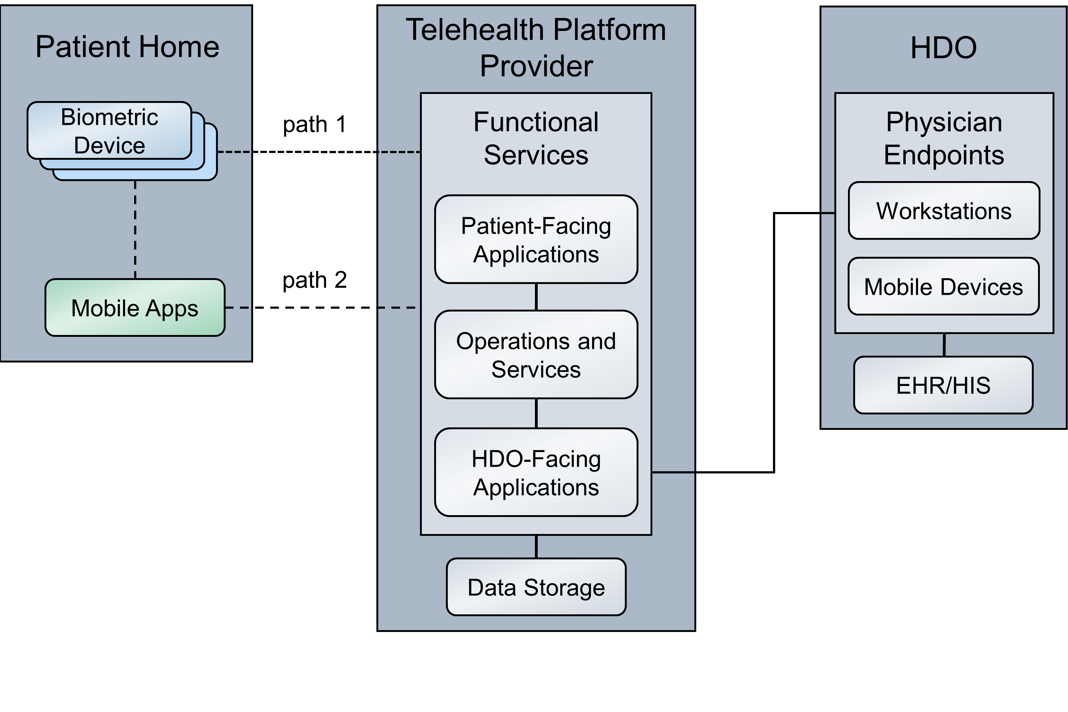
This practice guide implements a representative RPM solution as a distributed architecture. The solution deployed components across three domains that consist of the patient home, the telehealth platform provider, and the HDO. The patient home is the environment in which the patient lives and uses RPM components that include biometric monitoring devices, devices that the patient uses to communicate with their care team, and devices that the patient operates for personal use. This practice guide incorporates cloud-hosted telehealth platform providers within the architecture. The telehealth platform provider maintains components that include virtual or physical components with servers to manage, maintain, and receive data communications from either the patient home or the HDO. The HDO maintains its own environment and includes components such as workstations and clinical systems to receive and interpret patient data and record patient interactions in an electronic health record (EHR) system.
Figure 4‑1 illustrates a high-level RPM distributed architecture. The depicted architecture notes two primary paths by which network communications traverse. Path 1 shows biometric devices communicating with the telehealth platform provider whereas Path 2 shows the use of a mobile app. The mobile app operates on an interface device (i.e., a provisioned tablet). For Path 2, patients use the tablet to collect data from the biometric devices. Path 2 does not involve data transfer between the biometric device to the telehealth platform provider directly. Rather, patients collect biometric data with the tablet. Patients use the tablet for communications with data exchanges between the patient home and the telehealth platform provider.
Figure 4‑1 RPM Architecture
4.1 Layering the Architecture¶
The NCCoE healthcare lab stratified the distributed architecture with three layers: business, security, and infrastructure. The business layer focuses on functional capabilities that include biometric readings and patient interactions. The security layer conceptually describes how the NCCoE lab implements security capabilities. The NCCoE also implements an infrastructure layer that represents the network and communications environment.
The layers intersect each of the three domains. The patient home domain implements the business layer by using the biometric devices and interface device(s) that capture and relay biometric data from the patient and allow the patient to communicate with the clinical care team, respectively. The patient home may include a security layer component that segregates network traffic between the RPM components and personally-owned devices when the RPM devices use the same network infrastructure (e.g., over Wi-Fi) as the personally-owned devices. When devices operate and communicate over Wi-Fi, the infrastructure layer would consist of Wi-Fi access points, routers, and switches that the patient operates.
The telehealth platform provider domain also implements three layers. The business layer consists of services that facilitate handling patient data and web- or audioconferencing capabilities. The security layer consists of components used to secure the environment, such as authentication mechanisms, certificate management systems, and security logging capabilities. The infrastructure layer consists of network and server components that may be implemented as cloud services. Practitioners should note that this practice guide does not go into significant detail regarding security or infrastructure layer configurations for telehealth platform providers. As noted in this practice guide’s list of assumptions, it is assumed that telehealth platform providers have adequate privacy and security controls. These controls would align with the layer concept. HDOs should evaluate telehealth platform providers to determine control adequacy.
The HDO domain implements the business layer with applications and clinical systems used to support the RPM program. The security layer represents security capability deployment, which includes authentication mechanisms, network monitoring capabilities, and vulnerability scanning for example. The HDO implements the infrastructure layer with fundamental IT services such as Active Directory (AD), DNS, and networking devices.
Figure 4‑2 depicts a high-level view of the three layers intersecting each domain of these components and how we approached implementing them in the lab environment.
Figure 4‑2 Architecture Layers
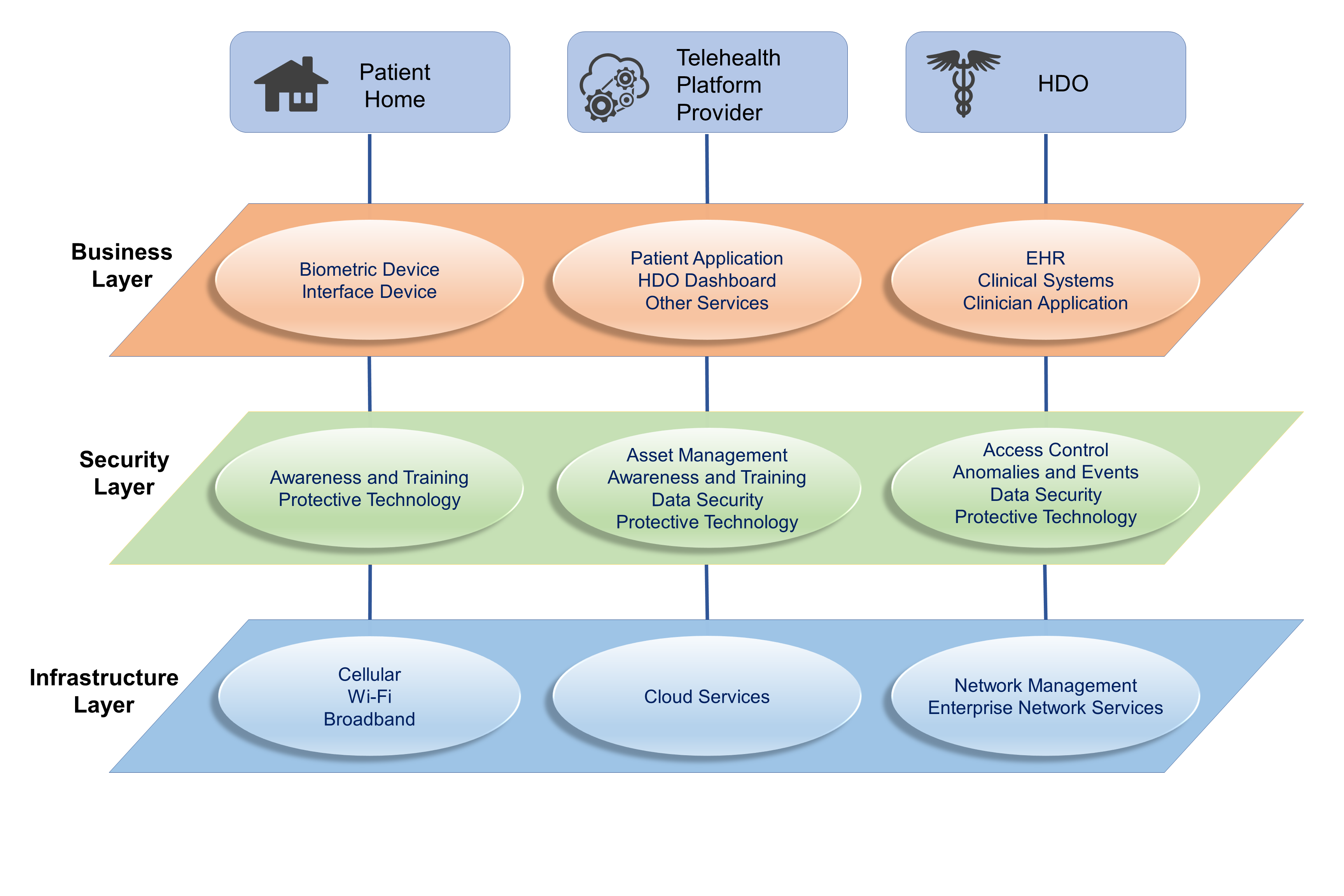
4.2 High-Level Architecture Communications Pathways¶
This practice guide describes an architecture that considers six different communications paths among the patient home, telehealth platform provider, and HDO. Figure 4‑3, RPM Communications Paths, shows the different paths labeled A through F. The different communications paths represent the varying modes by which the patient shares data with the clinician. Each path leads to the telehealth platform provider who receives the data and presents the data in an HDO-facing application. The clinician accesses data presented within an HDO-facing application via an app or application.
4.2.1 Cellular Data Pathways¶
The following communications pathways describe how patients use devices that are preconfigured with cellular data services. Telehealth platform providers may provision devices with cellular data capability to support ease of use and connectivity assurance and to ensure that the device may not be reachable by an untrusted internet connection (e.g., an arbitrary Wi-Fi hot spot).
Path A assumes that the biometric device has cellular communications. The telehealth platform provider deploys the biometric device with a preconfigured subscriber identity module, commonly referred to as a subscriber identity module (SIM) card. Option A does not include an RPM interface, such as a mobile device that may be a laptop, cellular phone, or tablet. The biometric device sends data over cellular data networks, which then route the data to the telehealth platform provider. The telehealth platform provider receives the data and displays it for clinicians to view through a portal or dashboard application. The clinician accesses the data through a clinician-facing app or application.
Path B assumes that the telehealth platform provider has deployed a biometric device and an RPM interface to the patient home. The RPM interface may be a mobile device such as a cellular phone or tablet. For this path, the biometric device forwards data to the RPM interface via Bluetooth. The RPM interface would include a SIM card that enables cellular data communication to the telehealth platform provider. The RPM interface would be deployed with an app to be used by the patient. The app would include an interface that allows the patient to forward the data to the telehealth platform provider.
4.2.2 Broadband Pathways¶
Telehealth platform providers may provide devices that leverage broadband internet connectivity provisioned at the patient home. Devices may use Wi-Fi or other communications protocols. Devices may transmit data that traverse a patient-provided internet router. The following pathways describe how data may flow when internet broadband is available.
Path C assumes that the telehealth platform provider has deployed a biometric device and an RPM interface to the patient home. The dataflow within the patient home domain is the same as Path B. However, rather than cellular communication, the RPM interface communicates with the telehealth platform provider via a broadband connection provided by the patient.
Path D has the same dataflow as Path C; however, external network transmissions traverse an add-on security device such as a Layer 2 over Layer 3 gateway.
Path E is like Path A; however, rather than cellular data, the path leverages a patient home broadband connection traversing an add-on security device such as a Layer 2 over Layer 3 gateway.
Path F is like Paths A and E. Path F leverages a patient home broadband connection; however, no other gateway is used. Data are sent directly to the telehealth platform provider over the public internet.
Figure 4‑3 RPM Communications Paths
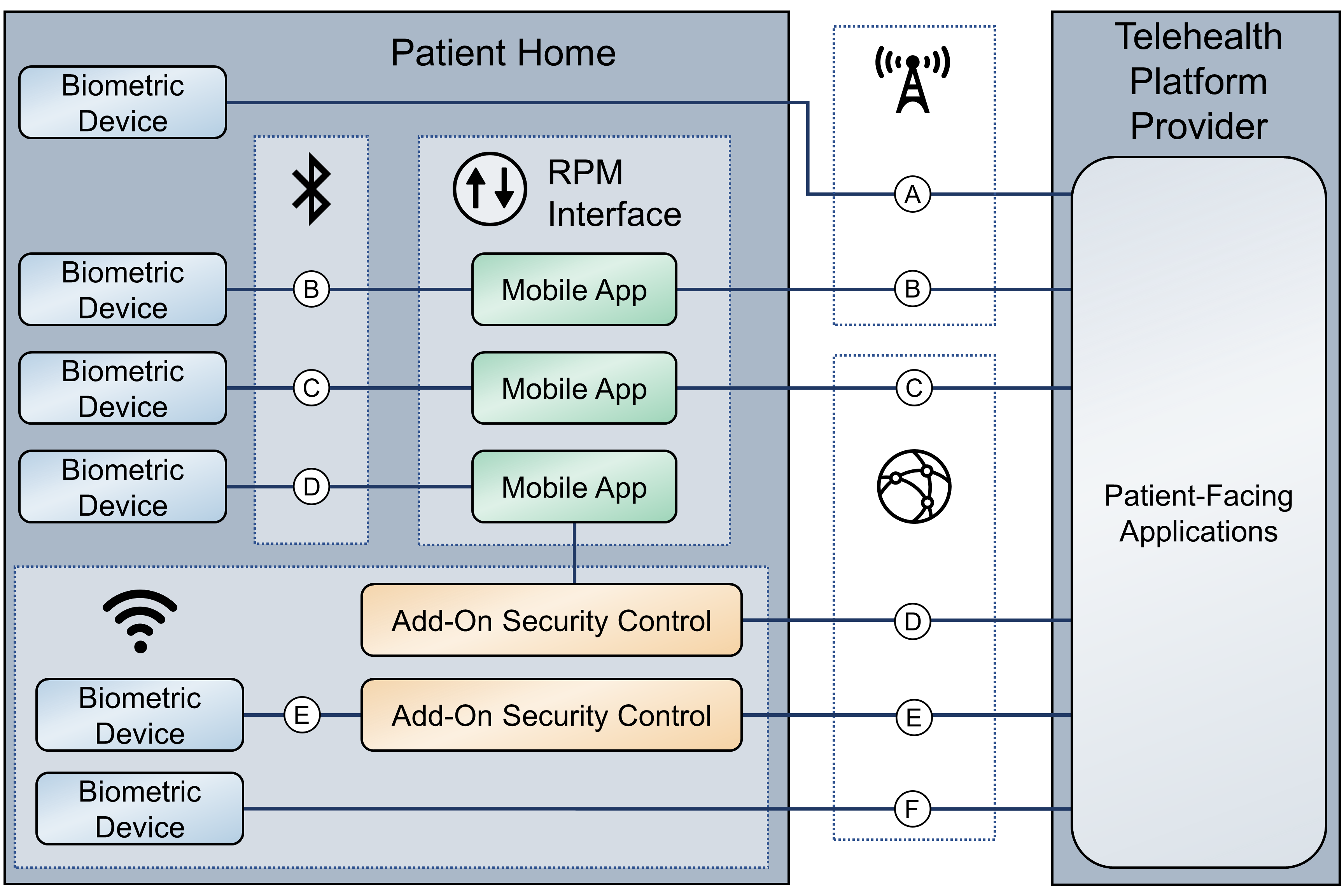
4.3 Data and Process Flows¶
To gain a high-level understanding of how RPM programs operate, this practice guide evaluates two use cases: diabetes and cardiac and pulmonary rehabilitation.
The World Health Organization defines diabetes as “a chronic, metabolic disease characterized by elevated levels of blood glucose (or blood sugar), which leads over time to serious damage to the heart, blood vessels, eyes, kidneys, and nerves” [B16]. A diabetes RPM program could be beneficial in identifying when a patient’s blood glucose levels are higher/lower than normal. Ensuring that a patient’s blood glucose levels remain in a normal range helps prevent long-term complications that diabetes could cause [B17]. Patients may receive biometric devices such as glucometers, blood pressure monitors, weight scales, and activity trackers. These biometric devices may be enabled with Bluetooth, Wi-Fi, or cellular data communications capabilities that allow patients to share biometric data with physicians. Physicians may continuously monitor patients’ biometric data to identify and prevent a potential problem from occurring.
HDOs may enroll patients with chronic heart or lung conditions such as chronic obstructive pulmonary disease or coronary heart disease into cardiac and pulmonary RPM rehabilitation programs. These programs help patients return to a normal life and reduce other risk factors such as high blood pressure, high blood cholesterol, and stress [B18], [B19].
Telehealth platform providers implement solutions by using biometric devices, services, and applications. While telehealth platform providers may develop and maintain services and applications, they collaborate with manufacturers to procure and manage biometric devices. Conceptually, the device manufacturer operates as an extension of the telehealth platform provider when delivering RPM solutions to patients.
As noted in Section 4.2, High-Level Architecture Communications Pathways, practitioners may implement RPM ecosystems where data communications involve different communications protocols or paths.
This practice guide examines two distinct dataflows. The first dataflow begins when the patient transmits data from the biometric device. The biometric device sends data to the device manufacturer. The telehealth platform provider retrieves the data and presents the data through an HDO-facing application. The clinician views the data from an app or application that interfaces with the patient data residing in the telehealth platform provider HDO-facing application.
The second dataflow begins when the patient transmits the data from the biometric device. A field gateway device, such as a mobile device that may be a tablet, mobile phone, or laptop, pulls the data from the biometric device. The patient uses the field gateway device to transport the data to the telehealth platform provider. The telehealth platform provider receives the data and presents it through an HDO-facing application. The clinician views the data from an app or application that interfaces with the patient data residing in the telehealth platform provider HDO-facing application.
Figure 4‑4 depicts the first dataflow sequence. This dataflow sequence demonstrates an RPM implementation that uses device vendor platforms to transmit data from a patient’s home to the telehealth platform provider. A patient begins the process by interfacing with the biometric device provided by the third-party platform, which in turn gathers the required medical readings. Once the device gathers the desired readings, the device transmits and stores the data to the device vendor’s local storage server. The third-party platform connects to the vendor’s storage server and pulls that data into its own local storage server. The platform then evaluates the received data and creates correlations among the retrieved data, the associated patient, and the primary care provider. If the platform identifies any areas of concern (such as high blood glucose readings for a diabetes use case) while evaluating the data, the platform sends an alert to the patient’s primary care provider for immediate action. Otherwise, the primary care provider will connect to the third-party platform’s web server to view the patient’s data on a dashboard. The physician/clinician will evaluate the data, modify the patient’s care plan, update the patient’s EHR, and contact the patient via video or audio call to update them on their new care plan.
Figure 4‑4 RPM Dataflow Option 1
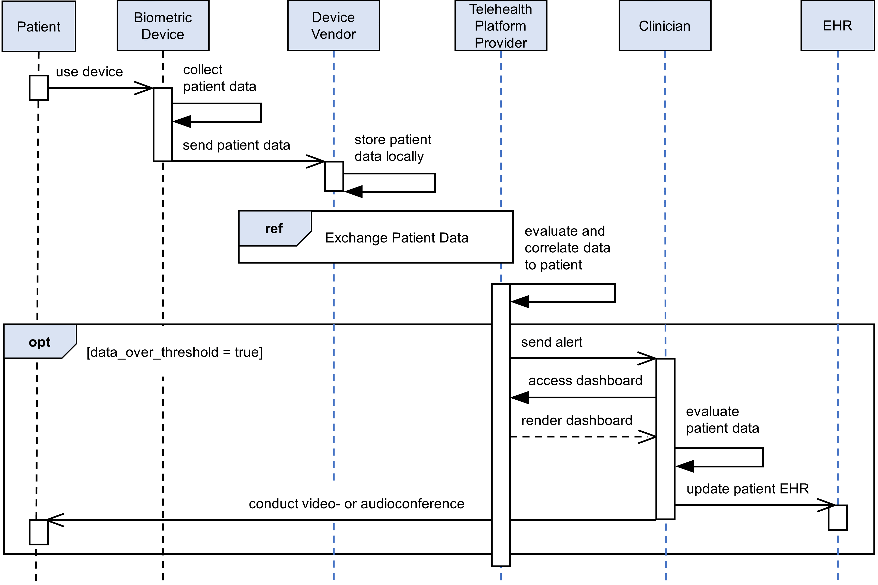
Figure 4‑5 depicts the second dataflow sequence. In this dataflow sequence, a patient begins the process by interfacing with the biometric device provided by the telehealth platform provider, which in turn collects the required medical readings. Once the data are collected, the device transmits the data to the mobile device. The patient interacts with the mobile device to answer survey questions associated with their program, providing a clinician more insight on the patient’s health. The patient uses the mobile device to collect data from all biometric devices associated with their RPM regimen. The patient then uses the mobile device to transmit the biometric device data and survey results. The mobile device pushes the grouped data to the telehealth platform provider. The telehealth platform provider presents the data to the primary care provider. The clinician connects to the telehealth platform provider’s web server to view the patient’s data on a dashboard. The clinician evaluates the data and may update the patient’s care plan. Then, the clinician may update the patient’s EHR and contact the patient via a mobile device to update them on their new care plan.
Figure 4‑5 RPM Dataflow Option 2
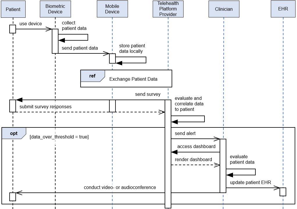
4.4 Security Capabilities¶
The project team implemented a lab environment that represented the three domains described in Section 4, Architecture. When building the HDO environment, the team built upon the zoned network architecture described in NIST SP 1800-8, Securing Wireless Infusion Pumps in Healthcare Delivery Organizations [B20]. The team used the network zoning approach as a baseline for the RPM ecosystem infrastructure. On top of the baseline, the team selected relevant security capabilities for appropriate domains. The selected security capabilities are:
telehealth platform provider
risk assessment controls
identity management, authentication, and access control
data security
anomalies and events and security continuous monitoring
HDOs bear risk when implementing RPM practices. The RPM environment is distributed across three domains and requires participation of the patient, the telehealth platform provider, and the HDO to assure that risks are adequately mitigated. This practice guide’s architecture describes deploying components in three domains, with threats and risks that may affect each domain distinctly. As organizations implement RPM solutions, they must include parties involved in managing the individual domains in recognizing and safeguarding against privacy and cybersecurity events that may occur within the respective domains.
Practitioners will note that the security capability descriptions focus primarily on the HDO domain. Capabilities are deployed to other domains to the extent that the HDO may have influence. HDOs may not authoritatively determine the control environment implemented by the telehealth platform provider. HDOs may obtain assurance that similar controls are implemented by the telehealth platform provider before establishing the relationship with the provider. HDOs should establish questionnaires or audit approaches that they may use in evaluating third parties such as telehealth platform providers. HDOs and telehealth platform providers are subject to regulatory requirements to ensure patient privacy and cybersecurity.
Telehealth platform providers are third parties that may implement security capabilities that do not necessarily use the tools standard to the HDO. Telehealth platform providers may provide services for many HDOs, and implementing the same tools for all HDOs may not be feasible from a technical perspective. Telehealth platform providers apply risk management approaches that are appropriate for their business model. While telehealth platform providers may manage risk by using different tools and techniques from the HDO, these providers should address the risk concerns for the HDO. Telehealth platform providers should apply similar measures, e.g., the NIST Cybersecurity Framework [B3] and Risk Management Framework [B4], that describe risk and control approaches. When evaluating telehealth platform providers, HDOs should review the privacy and security control policies and other documentation to ensure that the mitigation approaches that the telehealth platform provider implements are consistent with the HDO’s requirements.
HDOs and telehealth platform providers may find difficulties when implementing security capabilities on the patient home domain. Patients may find complex controls or practices onerous, and, therefore, they may be less likely to participate in the RPM program. Telehealth platform providers may implement security capabilities for end-point devices, such as biometric sensors or mobile devices, that are part of the RPM program. HDOs, in collaboration with telehealth platform providers, may offer education and awareness material to discuss appropriate use of RPM-deployed equipment with the patient.
4.4.1 Telehealth Platform Provider¶
Telehealth platform providers are discussed in this practice guide as a security capability. HDOs implementing RPM programs will depend on telehealth platform providers to enable communications between patients and clinicians. Also, for this practice guide, telehealth platform providers configure, manage, and maintain biometric devices and potentially other technology provided to the patient. HDOs engaging with telehealth platform providers to enable their RPM programs are responsible for ensuring that they apply due diligence and understand the privacy and security capabilities that the telehealth platform provider maintains. HDOs and partners with whom HDOs engage may be responsible for adhering to regulatory compliance and should ensure that HDOs have implemented measures that address compliance concerns as a baseline. Telehealth platform providers represent a third-party partner, and HDOs should evaluate their partners accordingly.
In addition to safeguarding systems that aggregate patient information, telehealth platform providers are responsible for assuring that the biometric devices that are deployed to the patient home include adequate controls that mitigate privacy and security risk. Biometric devices have characteristics that are similar to Internet of Things (IoT) architecture. Telehealth platform providers should consider clinical efficacy of the devices as well as assure that devices do not pose privacy or cybersecurity harm to the patient home or the broader RPM ecosystem. Appendix E, Benefits of Device Cybersecurity Requirements, discusses challenges that may be found in biometric devices that may be regarded as IoT. Appendix Eʼs roots are founded in a new set of guidance focused on IoT security. NIST is developing several documents that discuss how IoT device manufacturers may incorporate privacy and security measures in products. Telehealth platform providers may review IoT Device Cybersecurity Guidance for the Federal Government: Establishing IoT Device Cybersecurity Requirements (NIST SP 800-213) [B21]. While NIST SP 800-213 focuses on the federal government’s IoT deployment efforts, concepts found in the document may inform telehealth platform providers as they evolve their biometric device acquisition processes.
The NIST Cybersecurity Framework includes risk assessment under the Identify Function. This practice guide implements tools for vulnerability management.
The practice guide uses Tenable.sc with Nessus to perform vulnerability scanning and provide dashboard reports. Vulnerability scanning operates by applying signatures of known vulnerabilities. Components that operate within the HDO domain are subject to regular vulnerability scanning. As vulnerabilities are identified, patching or other mitigating approaches may be applied. Patches or updates to operating systems, apps, or applications may be applied as available.
4.4.2 Identity Management, Authentication, and Access Control¶
Identity management involves activities that discuss identity proofing and establishing credentials. Authentication for this practice guide provides the mechanisms that assure that authorized entities access the system after telehealth platform providers and HDOs establish respective credentials. Practitioners should refer to NIST SP 1800-24 (reference Section 5.3.3), Securing Picture Archiving and Communication System (PACS) [B14], which provides more in-depth discussion on identity management and access control. While that practice guide uses different tools and addresses a clinical practice different from RPM, concepts regarding identity management and authentication are relevant for this practice guide.
This practice guide builds upon a network zoning concept that was discussed in NIST SP 1800-8, Securing Wireless Infusion Pumps in Healthcare Delivery Organizations [B20]. Figure 4‑6 depicts the lab environment built for this practice guide. The diagram splits the infrastructure between the NCCoE and the RPM lab, with the latter representing the configured simulated environments for this practice guide. Focusing on the HDO cloud depiction, this practice guide simulates the HDO environment that is made up of enterprise services, health information system (HIS) services, remote services, databases, clinical workstations, and security services virtual local area networks (VLANs).
Figure 4‑6 Network Segmentation and VLAN Within the RPM Lab
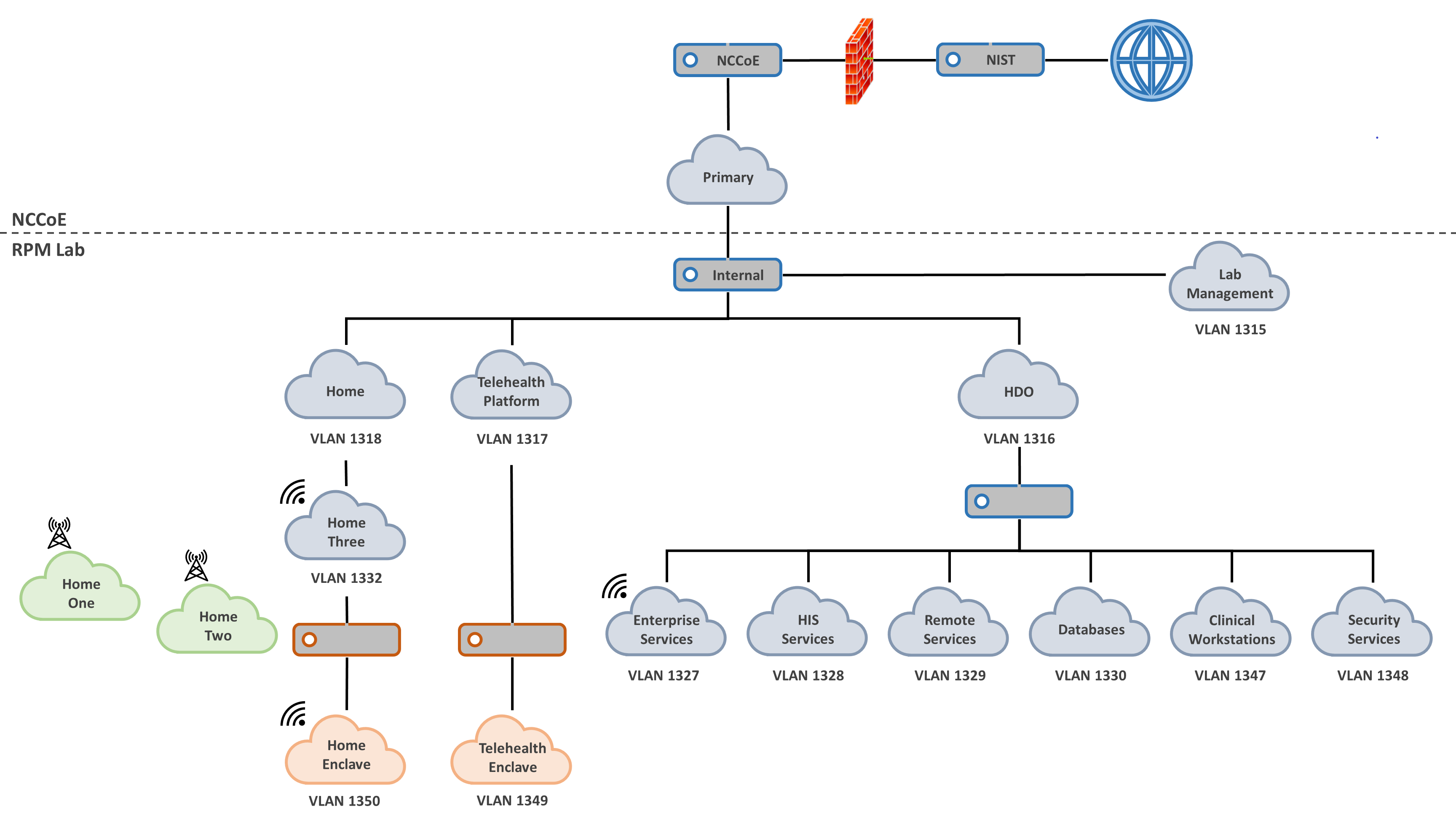
The practice guide extends the network zoning concept between the patient home and the telehealth platform provider. Biometric devices in the patient home using a Wi-Fi communications pathway that traverses a patient-provided broadband connection are secured using a layer 2 over layer 3 solution. In a simulated cloud environment, engineers deployed the layer 2 over layer 3 solution between zones that represent the patient home and a telehealth platform provider. The layer 2 over layer 3 solution segmented the biometric devices from the patient home network into a secured enclave. The enclave assures that network traffic from the patient home is not introduced or have visibility to the biometric devices. The layer 2 over layer 3 solution secures the data-in-transit communications between the patient home and telehealth platform provider domains respectively and adopts an approach that is consistent with concepts described in NIST SP 800-207, Zero Trust Architecture [B22].
4.4.3 Data Security¶
This practice guide examines challenges associated with data loss and data alteration. Communications initiate from the patient home, traversing a public communications channel, and are made accessible to clinicians via internet connectivity. This practice guide addresses the need to provide end-to-end data protection as a vital requirement to ensure RPM viability.
Network sessions are encrypted. Telehealth platform providers implement data security as they manage biometric devices and the dataflow between the patient home and solutions hosted by the telehealth platform provider. Stored data are protected through encryption. The project team examined dataflows and applied a privacy risk assessment that analyzed communications between the implemented components and identified how data-in-transit security controls are implemented.
4.4.4 Anomalies and Events and Security Continuous Monitoring¶
Managing anomalies and events and performing security continuous monitoring provides a proactive, real-time measure to determine that threats and vulnerabilities are appropriately recognized and mitigated within HDO environments. This practice guide implements several controls that address managing anomalies and events and performing security continuous monitoring. Security engineers require tools and processes to manage anomalies and events that include applying cyber threat intelligence (CTI), collecting and managing log information, and applying behavioral analytics. NIST describes CTI in NIST SP 800-150, Guide to Cyber Threat Information Sharing [B23]. NIST provides additional detail regarding security continuous monitoring in NIST SP 800-137 [B24].
4.5 Final Architecture¶
The project team built a reference architecture to include two communications pathways for biometric devices. In the first case, biometric devices in the patient home communicated to the telehealth platform provider over cellular data communications. The team built an architecture that addressed communications pathways A and B that were described in Section 4.2, High-Level Architecture Communications Pathways. In the second case, biometric devices communicated to a mobile device, and the mobile device leveraged the patient home Wi-Fi infrastructure. Mobile device communications to the telehealth platform provider are secured by a layer 2 over layer 3 solution through Onclave’s Secure IoT platform. Layer 2 over Layer 3 concepts are further described in Appendix F. This scenario aligns with pathway D described in Section 4.2.
Figure 4‑7 depicts the final architecture of the lab environment. The two telehealth platform providers, Accuhealth and Vivify, provided cloud-hosted solutions, with biometric devices deployed in respective home environments, described as Home One and Home Two. Biometric devices were provisioned and managed by the telehealth platform providers, with data communications over cellular data. A Home Three environment was provisioned to deploy biometric devices that would communicate over Wi-Fi. The architecture includes a telehealth platform provider hosted in a simulated cloud environment. Engineers implemented a layer 2 over layer 3 solution between Home 3 and the simulated cloud environment.
The architecture also includes an HDO environment with six network zones: Remote Services, Clinical Workstations, Enterprise Services, Databases, HIS Services, and Security Services.
Figure 4‑7 Final Architecture
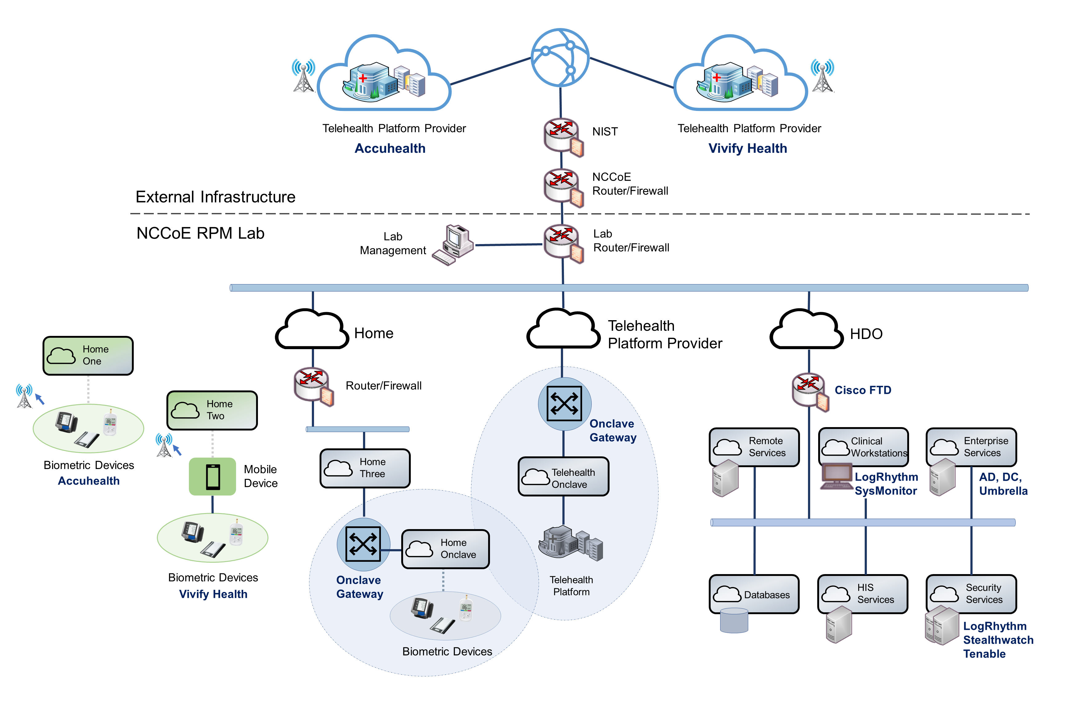
5 Security and Privacy Characteristic Analysis¶
The purpose of the security and privacy characteristic analysis is to understand the extent to which the project meets its objective of demonstrating the privacy and security capabilities described in the reference architecture in Section 4. In addition, it seeks to understand the security and privacy benefits and drawbacks of the example solution.
5.1 Assumptions and Limitations¶
The security characteristic analysis has the following limitations:
It is neither a comprehensive test of all security components nor a red-team exercise.
It cannot identify all weaknesses.
It does not include the lab infrastructure. It is assumed that devices are hardened. Testing these devices would reveal only weaknesses in implementation that would not be relevant to those adopting this reference architecture.
HDOs and telehealth platform providers implement an array of risk mitigation approaches that extend beyond what is discussed in this document. The broader array of controls consists of organizational structures, policies and procedures, and tools to support enterprise privacy and cybersecurity programs that this practice guide refers to as a set of pervasive controls.
HDOs and telehealth platform providers evaluate privacy risks throughout the RPM solution ecosystem and coordinate risk management roles and expectations with organizations that are part of the RPM solution.
5.2 Pervasive Controls¶
NIST SP 1800-24, Securing Picture Archiving and Communication System (PACS) [B14], described the use of controls that were termed “pervasive”. Subsequent practice guides such as this RPM practice guide discuss implementing controls that narrowly apply to the practice guide’s lab construction. Notwithstanding, HDOs and telehealth platform providers are enterprise organizations that may face a broader set of risks, including regulatory requirements, that extend beyond the narrow topic. The pervasive control concept assumes that HDOs and telehealth platform providers have implemented a comprehensive control set to address their risk and regulatory obligation.
For example, onboarding workforce members may involve identity proofing and creating and managing accounts and credentials. Organizations need to perform these activities to appropriately implement an enterprise risk management program. The requirement is not specific to RPM programs. These functions should be established prior to implementing an RPM program. Other controls, such as performing asset management, having incident response teams, and establishing incident response programs, should also be pervasive across the enterprise.
Another example is asset management. Asset management is a critical control that should be implemented by telehealth platform providers. Telehealth platform providers should maintain accurate inventories and manage configuration settings, patching, updates, and the overall life cycle for devices that are deployed to the patient home. While this is a requirement, the project team partnered with multiple telehealth platform providers. The team did not deploy security or privacy capabilities to the telehealth platform providers. Rather, it relied upon telehealth platform providers to implement an adequate and appropriate set of pervasive controls for their environment and for the services that they provide.
The NIST Cybersecurity Framework [B3] describes cybersecurity activities and outcomes that organizations should achieve for establishing or improving enterprise security programs. These activities and outcomes are articulated in the Subcategories of the Cybersecurity Framework Core. The Cybersecurity Framework provides the basis for pervasive controls, whereas this practice guide highlights implementation of selected controls. Readers should not regard the selected controls as the only controls that an HDO must implement. The selected controls that are described in this practice guide are a small subset of controls that HDOs and telehealth platform providers should implement. This practice guide’s descriptions of controls indicate how the selected controls were implemented in the lab environment.
5.3 Telehealth Platform Providers¶
Telehealth platform providers address several controls for the RPM solution. Telehealth platform providers configure, maintain, and manage devices that are deployed to the patient home domain. Telehealth platform providers provision devices to patients who have been enrolled in an RPM program by their HDO. Telehealth platform providers perform asset management for the provisioned devices and, thus, address ID.AM-1, ID.AM-2, ID.AM-4, ID.AM-5, ID.IM-P1, ID.IM-P2, and ID.IM-P7. Telehealth platform providers are responsible for addressing ID.RA-1.
Telehealth platform providers authenticate sessions based on the device identifier. When patients send or transfer data from biometric devices, data are routed to the telehealth platform provider. The telehealth platform provider receives the data and makes it available to clinicians and system users via a portal. Portals use unique identifiers for credentials (e.g., username/password) and role-based access control and ensure that connections to the portal are protected by using Transport Layer Security (TLS) 1.2.
For this practice guide, telehealth platform providers provisioned two classes of biometric devices: those that used cellular data communications and those that used the patient home-provided Wi-Fi network. In the first category, devices were explicitly not permitted to access Wi-Fi networks. Removing Wi-Fi capability separated RPM communication from network traffic that may have been present in the patient home domain. In the second case that deployed biometric devices that included Wi-Fi capability, those devices leveraged the patient home Wi-Fi environment and used a layer 2 over layer 3 solution to secure connectivity between the RPM devices and the telehealth platform provider.
For biometric devices that focused on cellular data communications, the project team used devices that were equipped to communicate over 4G Long-Term Evolution (LTE), which uses asymmetric encryption between the device and the cellular tower [B25]. Further investigation in data-in-transit protection was not determined in this practice guide.
The second case included biometric devices leveraged in the patient home Wi-Fi environment. Network sessions were secured using another product that provided in-transit protection using a layer 2 over layer 3 solution. The project team deployed dedicated gateway devices used to implement a network infrastructure that was consistent with NIST SP 800-207, Zero Trust Architecture [B22].
The telehealth platform provider addressed PR.AC-1, PR.AC-4, PR.DS-1, PR.DS-2, PR.DS-4, PR.DS-6, PR.PT-1, PR.PT-3, PR.PT-4, PR.AC-P1, PR.AC-P4, PR.DS-P1, PR.DS-P2, PR.DS-P4, PR.DS-P6, CT.DM-P8, PR.PT-P2, and PR.PT-P3.
The project team implemented telehealth platform provider services with Accuhealth and Vivify Health.
5.4 Risk Assessment (ID.RA and ID.RA-P)¶
This practice guide implemented tools that address elements of ID.RA-5 (threats, vulnerabilities, likelihoods, and impacts are used to determine risk) and ID.RA-P4. The project team implemented Tenable.sc to address vulnerability management. Tenable includes vulnerability scanning and dashboards that display identified vulnerabilities with scoring and other metrics that enable security engineers to prioritize.
Telehealth platform providers have separate infrastructures and organizational structures that require similar approaches. Telehealth platform providers may host their services with various implementations and may deploy similar solutions for their environments.
5.5 Identity Management, Authentication, and Access Control (PR.AC and PR.AC-P) Protective Technology
(PR.PT-P)¶
The engineers regarded many of the identity management Subcategories as part of a set of pervasive controls that have been discussed in NIST SP 1800-24, Securing Picture Archiving and Communication System (PACS) [B14]. HDOs and telehealth platform providers should apply similar solutions to address managing human, device, and system identities. Sample solutions are provided in NIST SP 1800-24.
Extending the network zoning concepts that were described in NIST SP 1800-8, Securing Wireless Infusion Pumps in Healthcare Delivery Organizations [B20], the project team implemented VLANs with firewall feature sets by using Cisco Firepower Threat Defense (FTD). This practice guide addresses PR.AC-5 by implementing VLANs that represent network zones found within an HDO. Telehealth platform providers may implement similar measures within their infrastructures.
The NIST Cybersecurity Framework implements identity management, authentication, and access control under the Protect Function by using the PR.AC Category. Within the HDO, the engineers implemented PR.AC-5 by using Cisco FTD to establish network zones as a set of VLANs. The network zones assure that components from each zone do not have implicit trust, and, thus, compromises on end points found in one zone are limited in their ability to affect devices that operate in other zones.
The Onclave Secure IoT platform creates unique enclaves within the patient home and the telehealth platform provider with their own root of trust for implicit trust.
The engineers implemented three primary Cisco tools for the HDO environment: Cisco Firepower, Cisco Umbrella, and Cisco Stealthwatch. As noted, the project team used Firepower to create and manage VLANs within the environment. Cisco Firepower includes a central management dashboard that allowed security engineers to configure and manage other features within the Cisco suite of tools. Firepower also includes intrusion detection capability and visibility into network traffic and network analytics that enabled engineers to detect and analyze events, monitor the network, and detect malicious code and, thus, addressed DE.AE-2, DE.CM-1, and DE.CM-4. Cisco Firepower addressed PR.AC-5, PR.PT-4, PR.AC-P5, and PR.PT-P3. The engineers implemented Cisco Umbrella for DNS and IP layer security and provided content and application filtering. Cisco Umbrella addressed DE.CM-4. The team also used Cisco Stealthwatch that implemented behavioral analytics capabilities and provided malware detection. Cisco Stealthwatch addressed PR.DS-5, PR.PT-4, DE.AE-1, DE.CM-1, PR.DS-P5, and PR.PT-P3.
Within the HDO domain, engineers implemented an AD to establish user accounts. AD credentials provided engineers with authentication for several components deployed in the lab. The lab’s AD implementation addresses PR.AC-1, PR.AC-4, PR.AC-P1, and PR.AC-P4.
The telehealth platform provider assures that PR.AC-5, PR.AC-6, PR.AC-7, PR.AC-P5, and PR.AC-P6 are met by managing components that are deployed to the patient home. Components that are deployed by the telehealth platform provider are fully managed devices that have been preconfigured and distributed by Accuhealth. The RPM components that Accuhealth provided for the patient home use a cellular communication pathway where unauthorized individuals may not remove or alter SIM cards. The cellular data communication pathway assures that the RPM components are segregated from untrusted devices that may operate in the patient home and, thus, implements PR.AC-5 and PR.AC-P5.
This practice guide also simulated a use case where a telehealth platform provider provides RPM components that use patient-provided broadband. The simulated test case implements Vivify components; however, it does not reflect how Vivify hosts its services. Biometric devices communicate with an interface device (e.g., the tablet). The simulated environment includes centralized configuration management for interface devices such as the tablet. Management prevents end users from modifying tablet configuration settings or installing unauthorized software. In this use case, biometric devices leverage the patient home Wi-Fi. Engineers secured the devices by leveraging a layer 2 over layer 3 solution to create a secure enclave. The solution segments the biometric devices from the patient home network, with only the biometric devices enabled to communicate over the secure enclave. The secure enclave solution included gateways implemented at the patient home and the simulated telehealth provider. The secure enclave solution supports PR.AC-1, PR.AC-3, PR.AC-4, PR.AC-5, and PR.PT-4.
RPM-enrolled patients are predetermined by the HDO, and the telehealth platform provider provisions RPM components to an established, known set of patients. HDOs enrolling patients in the RPM program partially addresses PR.AC-1 and PR.AC-P1. Clinicians identifying patients may be regarded as performing an identity-proofing activity, whereas telehealth platform providers may complete PR.AC-1 and PR.AC-P1 activities by creating accounts or records that relate to the patient and the RPM equipment that the patient receives.
Patient-provided (e.g., “bring your own device”) biometric devices were excluded in this practice guide’s architecture. The telehealth platform provider manages patient home-deployed components and, thus, assures that PR.AC-6 and PR.AC-P6 are addressed.
For this practice guide, the telehealth platform provider manages components that it procured and configured. The telehealth platform provider configures the devices to include authenticators that enforce component authentication. For this practice guide, only biometric devices that are managed by telehealth platform providers are provisioned authenticators. This implements PR.AC-7 and PR.AC-P6. Patient homes may include other devices, such as personally-owned devices, that are not a part of the RPM ecosystem. Devices that are not managed by telehealth platform providers do not have authentication credentials for the RPM solution. One should note that this practice guide simulated a telehealth platform provider when exploring biometric devices that communicate over broadband.
5.6 Data Security (PR.DS and PR.DS-P)¶
This practice guide implemented PR.DS-2 and PR.DS-P2 to ensure that data-in-transit are protected. HDOs connecting to cloud-hosted consoles used TLS 1.2 [B26]. The telehealth platform provider assured implementation of PR.DS-3 and PR.DS-P3 for RPM biometric devices deployed to the patient home.
For biometric devices that communicate over broadband, the project team secured network sessions using a layer 2 over layer 3 solution that is established using the Onclave Secure IoT platform. The solution segmented biometric devices and their communication from the patient home network. Network sessions between the patient home and the simulated telehealth platform provider used TLS 1.2. The Onclave Secure IoT platform used a key management mechanism that is consistent with guidance from NIST SP 800-57 Part 1, Revision 5, Recommendation for Key Management: Part 1–General [B27]. The Onclave IoT Platform solution secured sessions using a private blockchain. Data-in-transit used Advanced Encryption Standard (AES)-256 encryption [B28]. This addresses PR-DS-2 and PR-DS.5 for communications between the patient home and the simulated telehealth platform provider.
Accuhealth and Vivify Health use AES-256 encryption [B28] for data-at-rest and address PR.DS-1 and PR.DS-P1.
5.7 Anomalies and Events, Security Continuous Monitoring (DE.AE, DE.CM), and Data Processing Management
(CT.DM-P)¶
The project team implemented LogRhythmXDR as a security incident and event management (SIEM) tool. End-point devices that include servers and network infrastructure components generate log data that were aggregated in the SIEM tool for analysis. LogRhythm included two components: LogRhythmXDR and LogRhythm NetworkXDR. SIEM capabilities provide security engineers a baseline of network operations and allow security engineers to determine expected dataflows for users and systems. Engineers can detect events and analyze potential threats. LogRhythmXDR, therefore, is a SIEM that addresses NIST Cybersecurity Framework Subcategories ID.RA-5, PR.PT-1, DE.AE-1, DE.AE-2, ID.RA-P4, and CT.DM-P8. LogRhythm NetworkXDR provides capabilities that assure that the network is monitored for potential cybersecurity threats. It also provides assurance that unauthorized mobile code is detected and, thus, addresses DE.CM-7. This practice guide assures implementation of a network monitoring capability based on regular log collection and applies the SIEM analytics and automated response capabilities. The project team implemented Cisco Firepower, Cisco Stealthwatch, and Cisco Umbrella, which detects malicious code, detects unauthorized mobile code and provides continuous network monitoring and analytics. Therefore, the Cisco suite addresses DE.CM-4 and DE.CM-5.
6 Functional Evaluation¶
This practice guide uses the NIST Cybersecurity Framework. The Cybersecurity Framework includes Category and Subcategory concepts that allowed the project team to develop a reference architecture. The reference architecture reflects use cases and dataflows analyzed by the NCCoE. This practice guide aligns privacy and cybersecurity tools to Cybersecurity Framework Subcategories. The reference architecture depicts where tools were deployed.
6.1 RPM Functional Test Plan¶
One aspect of our security evaluation involved assessing how well the reference design addresses the security characteristics that it was intended to support. The Cybersecurity Framework Categories and Subcategories were used to provide structure to the security assessment by consulting the specific sections of each standard that are cited in reference to a Subcategory. The cited sections provide validation points that the example solution would be expected to exhibit. Using the Cybersecurity Framework Subcategories as a basis for organizing our analysis allowed us to systematically consider how well the reference design supports the intended security characteristics.
6.1.1 RPM Functional Evaluation¶
Table 6‑1 identifies the RPM functional evaluation addressed in the test plan and associated test cases. The evaluations are align ed with the basic architecture design and capability requirements from Section 4, Architecture.
Table 6‑1 Functional Evaluation Requirements
Cybersecurity Framework Category |
Relevant Cybersecurity Framework Subcategories |
Identifier |
Requirement |
Domain |
Test Case |
|---|---|---|---|---|---|
asset management |
ID.AM-1 ID.AM-5 |
CR-1 |
device management |
home telehealth platform provider |
RPM-1 |
risk assessment |
ID.RA-1 ID.RA-4 ID.RA-5 ID.RA-6 |
CR-2 |
end-point vulnerability scanning |
HDO |
RPM-2 |
identity management, authentication, and access control |
PR.AC-1 PR.AC-2 PR.AC-3 PR.AC-4 PR.AC-5 PR.AC-6 |
CR-3 |
role-based access |
telehealth platform provider |
RPM-3 |
CR-4 |
domain user authentication |
HDO |
RPM-4 |
||
CR-5 |
domain user authorization |
HDO |
RPM-4 |
||
CR-6 |
network segmentation |
HDO |
RPM-5 |
||
CR-7 |
access control policy |
HDO |
RPM-5 |
||
security continuous monitoring |
DE.CM-1 DE.CM-2 DE.CM-4 DE.CM-7 DE.CM-8 |
CR-8 |
malware protection |
HDO |
RPM-6 |
CR-9 |
anomaly detection |
HDO |
RPM-7 |
||
CR-10 |
LogRhythm |
HDO |
RPM-8 |
||
CR-11 |
LogRhythm |
HDO |
RPM-9 |
||
data security |
PR.DS-2 |
CR-12 |
data-in-transit is protected. |
home telehealth platform provider |
RPM-10 |
N/A |
N/A |
CR-13 |
business workflow |
home telehealth platform provider HDO |
RPM-11 |
6.1.2 Test Case: RPM-1¶
Cybersecurity Framework Category |
Asset Management |
Testable Requirement(s) |
(CR-1) device management |
Description |
Demonstrate the ability to verify that provisioned devices are associated with the intended patient who has enrolled in an RPM program. |
Preconditions |
|
Procedure |
Verify the patient/device association in the Accuhealth system.
Verify that data from the RPM devices are being sent to Accuhealth and associated with the correct patient.
|
Expected Results |
|
Actual Results |
Accuhealth provisioned an instance of its telehealth platform along with doctor-level accounts and sample patients associated with these accounts. We also received three RPM devices from Accuhealth: blood pressure monitor, blood glucose monitor, and digital scale. Accuhealth associated these RPM devices with the sample patients, which we verified by checking the Device ID information for each patient. Once the devices were received, we configured them and recorded sample measurements from each one. With the measurements taken, we logged in to the Accuhealth platform with the doctor-level account and viewed the Vitals information for each patient. As expected, the blood pressure and weight measurements were associated with Regina Houston’s patient record, and the blood glucose measurement was associated with Janelle Kouma’s patient record. |
6.1.3 Test Case: RPM-2¶
Cybersecurity Framework Category |
Risk Assessment |
Testable Requirement(s) |
(CR-2) end-point vulnerability scanning |
Description |
Demonstrate the ability to perform vulnerability scans on assets and view results in a dashboard format with risk-scoring evaluations. |
Preconditions |
|
Procedure |
Perform scans and view the results.
|
Expected Results |
|
Actual Results |
Using Tenable.sc, we ran a host discovery scan followed by a basic network scan. Once both scans were finished, we returned to the Tenable.sc dashboard and were able to view the results. The Nessus scanner was able to identify end points in the scan zones (VLANs) as well as potential vulnerabilities with associated risk scores. |
6.1.4 Test Case: RPM-3¶
Cybersecurity Framework Category |
Identity Management, Authentication, and Access Control |
Testable Requirement(s) |
(CR-3) role-based access |
Description |
Demonstrate the ability to limit and disable access to data by implementing role-based access control on the Vivify platform. |
Preconditions |
|
Procedure |
Create a Clinical Level 1 user account, and test account privileges.
Create a Clinical Level 2 user account, and test account privileges.
Create a Clinical Level 3 user account, and test account privileges.
|
Expected Results |
|
Actual Results |
We started by logging in to the provisioned Vivify portal with our admin credentials and creating three new Care Team users, each with their own access levels. The first user was granted Clinical Level 1 and was added as Care Team of the test patient; the second was granted Clinical Levels 1 and 2 and was added as Care Team of the test patient; and the third was granted Clinical Levels 1 through 3. Then we logged in as each new user and tested their privileges. The first user was able to only view patient records that were assigned to her. The second user was able to view and modify patient records that associated only with those assigned to her. The third user was able to view and modify all patient records. |
6.1.5 Test Case: RPM-4¶
Cybersecurity Framework Category |
Identity Management, Authentication, and Access Control |
Testable Requirement(s) |
(CR-4) domain user authentication (CR-5) domain user authorization |
Description |
Demonstrate the ability to create new domain users and enforce restrictions on nonadmin users. |
Preconditions |
|
Procedure |
Create a nonadmin domain user.
Create an admin domain user.
Create network share folder.
Test ability to access network share folder with nonadmin user.
Test ability to access network share folder with admin user.
|
Expected Results |
|
Actual Results |
Once the user accounts were created and the network share folder was created and configured, we began by logging in to a domain computer with the nonadmin domain user. The user was able to successfully log in. Next, we tested the user’s ability to access the network share folder. The nonadmin domain user was not able to access the network share folder, receiving a network error stating that the user did not have the proper permissions. Finally, we were able to successfully log in to a domain computer with the admin domain user’s account. With this user, we were also able to successfully access the network share folder and view the files within. |
6.1.6 Test Case: RPM-5¶
Cybersecurity Framework Category |
Identity Management, Authentication, and Access Control |
Testable Requirement(s) |
(CR-6) network segmentation (CR-7) access control policy |
Description |
Demonstrate the use of network segmentation and an access control policy to allow permitted traffic to selected network devices. |
Preconditions |
|
Procedure |
Test connectivity between devices in the same subnet.
Test connectivity between devices in separate subnets with no access control policy rules set.
Test connectivity between devices in separate subnets with an access control policy rule set to allow.
|
Expected Results |
|
Actual Results |
When the workstation and server were both placed inside the Clinical Workstations VLAN, the workstation was able to access the server’s web service, successfully displaying the server’s default IIS web page. After the server was moved to the HIS Services VLAN, the workstation was no longer able to reach the server’s web service. Instead of displaying the default IIS web page, the workstation’s internet browser returned an error code and stated that the web service could not be reached. A new access control policy rule was created and applied to the Cisco FTD, allowing hypertext transfer protocol (HTTP) traffic from the workstation to the server. Once the rule was created, the workstation was able to access the server’s web service and display the default IIS web page. |
6.1.7 Test Case: RPM-6¶
Cybersecurity Framework Category |
Security Continuous Monitoring |
Testable Requirement(s) |
(CR-8) malware protection |
Description |
Demonstrate the ability to protect the network and end points from malicious services by blocking the service before a connection is made. |
Preconditions |
|
Procedure |
Test connectivity to outside malicious service with no Umbrella policy.
Test connectivity to outside malicious service with Umbrella policy.
|
Expected Results |
|
Actual Results |
To start, the Cisco Umbrella policy applied to the Forwarder appliances was not configured to block external sites that have been flagged for potential malware. Using a workstation in the Clinical Workstations VLAN, we navigated to a test malware site hosted by Cisco (examplemalwaredomain.com) to verify Cisco Umbrella’s effectiveness. Without the malware policy in place, the workstation was able to successfully reach the test malware site. After this, the Cisco Umbrella policy was configured to block external sites that have been flagged for potential malware. With the policy in place, the workstation was used again to connect to the test malware site, this time receiving a Cisco Umbrella block page notifying us that access to the site was not permitted. |
6.1.8 Test Case: RPM-7¶
Cybersecurity Framework Category |
Security Continuous Monitoring |
Testable Requirement(s) |
(CR-9) malicious activity detection |
Description |
Demonstrate the ability to detect anomalous network traffic and create an alert for further investigation. |
Preconditions |
|
Procedure |
Configure Cisco Stealthwatch policy rule.
Test ability for Cisco Stealthwatch to detect a network discovery scan and create an alert.
|
Expected Results |
|
Actual Results |
Once the Cisco Stealthwatch policy rule had been created, it took roughly a minute after the Nmap scan had run to begin displaying alerts on the Cisco Stealthwatch dashboard. The Ubuntu workstation from which the scans originated, 192.168.41.10, was listed on the dashboard under Top Alarming Hosts and was also listed in the Recon category under Today’s Alarms. On top of triggering the Recon rule that we had created, the scans also triggered a New Flows Initiated alarm for exceeding a threshold number of new flows within a set period. |
6.1.9 Test Case: RPM-8¶
Cybersecurity Framework Category |
Security Continuous Monitoring |
Testable Requirement(s) |
(CR-10) end-point monitoring and protection |
Description |
Demonstrate the ability to detect unusual authentication behaviors and file integrity changes on protected end points. |
Preconditions |
|
Procedure |
Enable user activity monitor services on the Clinical Workstation.
Create a file integrity monitor policy for the Clinical Workstation.
Create an artificial intelligence (AI) engine rule.
Test user activity monitoring.
View user authentication failure alerts.
Test file integrity monitoring.
|
Expected Results |
|
Actual Results |
Once LogRhythmXDR was configured to provide user activity monitoring and file integrity monitoring, we began by testing the user activity monitoring. For this test, we powered on the Windows Server in the Clinical Workstations VLAN that had been configured with a LogRhythm System Monitor Agent. We made five consecutive login attempts using an invalid password, which was then detected by LogRhythm, and an alert was created that was visible on the LogRhythm Web Console. Next, we tested the file integrity monitoring. For this test, we logged in to the Windows Server in the Clinical Workstations VLAN and made some modifications to the testfile text document in the C:testdirectory folder. Once the changes had been saved, an alarm was triggered and visible in the LogRhythm Web Console. From the alert, we could also drill down to the event and determine what user had made the modification. |
6.1.10 Test Case: RPM-9¶
Cybersecurity Framework Category |
Security Continuous Monitoring |
Testable Requirement(s) |
(CR-11) end-point network access monitoring |
Associated Test Case(s) |
|
Description |
This test case demonstrates the ability to create alarms for unauthorized network traffic. |
Preconditions |
|
Procedure |
Enable user network connection monitor on the Clinical Workstation.
Create an AI engine rule.
Test user network connectivity monitoring.
View user network connectivity monitoring alerts.
|
Expected Results |
|
Actual Results |
Once LogRhythmXDR and NetworkXDR were configured to provide user network connection monitoring, we powered on the Windows Server in the Clinical Workstations VLAN that had been configured with a LogRhythm System Monitor Agent. After logging in, we opened a web browser and connected to http://www.msn.com/. LogRhythm detected use of the http protocol and created an alert that was visible on the LogRhythm Web Console. |
6.1.11 Test Case: RPM-10¶
Cybersecurity Framework Category |
Data Security |
Testable Requirement(s) |
(CR-12) data-in-transit is protected |
Description |
Demonstrate the ability to protect data-in-transit between the patient home and the telehealth platform. |
Preconditions |
|
Procedure |
Verify that the Vivify Pathways Care Team Portal is operational.
Test connectivity between the mobile device and Vivify Portal when connected to the Onclave Wireless Home Gateway.
Test connectivity between the mobile device and Vivify Portal when not connected to the Wireless Onclave Home Gateway.
|
Expected Results |
|
Actual Results |
The mobile device successfully transmitted data to the Vivify Portal when connected to the Wireless Onclave Home Gateway. The Wireshark packet analysis tool was used to capture network traffic. Captured traffic was observed to be encrypted. When the mobile device was not connected to the Wireless Onclave Home Gateway, data were not transmitted to the Vivify Portal. |
6.1.12 Test Case: RPM-11¶
Cybersecurity Framework Category |
N/A |
Testable Requirement(s) |
(CR-13) business workflow |
Description |
Demonstrate that the telehealth platform provider can receive a patient’s biomedical data from the patient home and present this data to the HDO. |
Preconditions |
|
Procedure |
Accuhealth–gather biomedical readings from devices with a cellular connection.
Accuhealth–view and verify that patient data were stored in the telehealth platform from the HDO network.
Vivify—gather biomedical readings from devices with a broadband connection.
Vivify–view and verify that patient data were stored in the telehealth platform from the HDO network.
|
Expected Results |
|
Actual Results |
Biomedical readings were transmitted from the patient’s home to the telehealth platform provider. Clinicians were also able to access and view the patient’s biomedical readings from the HDO network by logging in to the third party’s platform and using their provided credentials. |
7 Future Build Considerations¶
This practice guide implemented biometric devices that used cellular data communications. This guide also addressed biometric devices using broadband communications. The practice guide implemented Onclave Networks as a proof-of-concept solution that provides layer 2 over layer 3 protection in a zero trust architecture model. This practice guide simulated a telehealth platform provider and deployed the Onclave solution to demonstrate how data communications between the patient home and telehealth platform provider may be secured. The solution assures that biometric devices are segmented from other devices that may appear in a patient home network.
A future build may also implement an EHR system that would receive automated data from the telehealth platform provider. Patient-initiated messages from RPM components deployed to the patient home were contained within the RPM systems hosted within an application to which HDOs connected for review and analysis. The future build may include direct messaging from the RPM systems to the EHR.