NIST SPECIAL PUBLICATION 1800-24C
Securing Picture Archiving and Communication System (PACS):
Cybersecurity for the Healthcare Sector
Volume C:
How-to Guides
Jennifer Cawthra
National Cybersecurity Center of Excellence
National Institute of Standards and Technology
Bronwyn Hodges
Kevin Littlefield
Chris Peloquin
Sue Wang
Ryan Williams
Kangmin Zheng
The MITRE Corporation
McLean, Virginia
December 2020
FINAL
This publication is available free of charge from: https://doi.org/10.6028/NIST.SP.1800-24
The first draft of this publication is available free of charge from: https://www.nccoe.nist.gov/library/securing-picture-archiving-and-communication-system-nist-sp-1800-24-practice-guide

DISCLAIMER
Certain commercial entities, equipment, products, or materials may be identified by name of company logo or other insignia in order to acknowledge their participation in this collaboration or to describe an experimental procedure or concept adequately. Such identification is not intended to imply special status or relationship with NIST or recommendation or endorsement by NIST or NCCoE; neither is it intended to imply that the entities, equipment, products, or materials are necessarily the best available for the purpose.
National Institute of Standards and Technology Special Publication 1800-24C, Natl. Inst. Stand. Technol. Spec. Publ. 1800-24C, 255 pages, (December 2020), CODEN: NSPUE2
FEEDBACK
As a private-public partnership, we are always seeking feedback on our practice guides. We are particularly interested in seeing how businesses apply NCCoE reference designs in the real world. If you have implemented the reference design, or have questions about applying it in your environment, please email us at hit_nccoe@nist.gov.
All comments are subject to release under the Freedom of Information Act.
NATIONAL CYBERSECURITY CENTER OF EXCELLENCE
The National Cybersecurity Center of Excellence (NCCoE), a part of the National Institute of Standards and Technology (NIST), is a collaborative hub where industry organizations, government agencies, and academic institutions work together to address businesses’ most pressing cybersecurity issues. This public-private partnership enables the creation of practical cybersecurity solutions for specific industries, as well as for broad, cross-sector technology challenges. Through consortia under Cooperative Research and Development Agreements (CRADAs), including technology partners—from Fortune 50 market leaders to smaller companies specializing in information technology security—the NCCoE applies standards and best practices to develop modular, adaptable example cybersecurity solutions using commercially available technology. The NCCoE documents these example solutions in the NIST Special Publication 1800 series, which maps capabilities to the NIST Cybersecurity Framework and details the steps needed for another entity to re-create the example solution. The NCCoE was established in 2012 by NIST in partnership with the State of Maryland and Montgomery County, Maryland.
NIST CYBERSECURITY PRACTICE GUIDES
NIST Cybersecurity Practice Guides (Special Publication 1800 series) target specific cybersecurity challenges in the public and private sectors. They are practical, user-friendly guides that facilitate the adoption of standards-based approaches to cybersecurity. They show members of the information security community how to implement example solutions that help them align with relevant standards and best practices, and provide users with the materials lists, configuration files, and other information they need to implement a similar approach.
The documents in this series describe example implementations of cybersecurity practices that businesses and other organizations may voluntarily adopt. These documents do not describe regulations or mandatory practices, nor do they carry statutory authority.
ABSTRACT
Medical imaging plays an important role in diagnosing and treating patients. The system that manages medical images is known as the picture archiving communication system (PACS) and is nearly ubiquitous in healthcare environments. PACS is defined by the Food and Drug Administration as a Class II device that “provides one or more capabilities relating to the acceptance, transfer, display, storage, and digital processing of medical images.” PACS centralizes functions surrounding medical imaging workflows and serves as an authoritative repository of medical image information.
PACS fits within a highly complex healthcare delivery organization (HDO) environment that involves interfacing with a range of interconnected systems. PACS may connect with clinical information systems and medical devices and engage with HDO-internal and affiliated health professionals. Complexity may introduce or expose opportunities that allow malicious actors to compromise the confidentiality, integrity, and availability of a PACS ecosystem.
The NCCoE at NIST analyzed risk factors regarding a PACS ecosystem by using a risk assessment based on the NIST Risk Management Framework. The NCCoE also leveraged the NIST Cybersecurity Framework and other relevant standards to identify measures to safeguard the ecosystem. The NCCoE developed an example implementation that demonstrates how HDOs can use standards-based, commercially available cybersecurity technologies to better protect a PACS ecosystem. This practice guide helps HDOs implement current cybersecurity standards and best practices to reduce their cybersecurity risk and protect patient privacy while maintaining the performance and usability of PACS.
KEYWORDS
access control; auditing; authentication; authorization; behavioral analytics; cloud storage; DICOM; EHR; electronic health records; encryption; microsegmentation; multifactor authentication; PACS; PAM; picture archiving and communication system; privileged account management; vendor neutral archive; VNA
ACKNOWLEDGMENTS
We are grateful to the following individuals for their generous contributions of expertise and time.
Name |
Organization |
|---|---|
Matthew Hyatt |
Cisco |
Kevin McFadden |
Cisco |
Cletis McLean |
Cisco |
Peter Romness |
Cisco |
Deidre Cruit |
Clearwater Compliance |
Mike Nelson |
DigiCert |
Taylor Williams |
DigiCert |
Andy Gray |
Forescout |
Katherine Gronberg |
Forescout |
William Canter |
Hyland |
Kevin Dietz |
Hyland |
Joseph Davis |
Microsoft |
Janet Jones |
Microsoft |
Dan Menicucci |
Microsoft |
Mehwish Akram |
The MITRE Corporation |
Steve Edson |
The MITRE Corporation |
Sallie Edwards |
The MITRE Corporation |
Donald Faatz |
The MITRE Corporation |
Harry Perper |
The MITRE Corporation |
David Alfonso |
Philips Healthcare |
Jonathan Bagnall |
Philips Healthcare |
Julian Castro |
Philips Healthcare |
Sukanta Das |
Philips Healthcare |
Jason Dupuis |
Philips Healthcare |
Michael McNeil |
Philips Healthcare |
Dwayne Thaele |
Philips Healthcare |
Steve Kruse |
Symantec |
Derek Peters |
Symantec |
Axel Wirth |
Symantec |
Bill Johnson |
TDi Technologies |
Pam Johnson |
TDi Technologies |
Robert Armstrong |
Tempered Networks |
Nicholas Ringborg |
Tempered Networks |
Randy Esser |
Tripwire |
Onyeka Jones |
Tripwire |
Jim Wachhaus |
Tripwire |
Sandra Osafo |
University of Maryland University College |
Henrik Holm |
Virta Labs |
Michael Holt |
Virta Labs |
Ben Ransford |
Virta Labs |
Jun Du |
Zingbox |
Damon Mosk-Aoyama |
Zingbox |
David Xiao |
Zingbox |
The Technology Partners/Collaborators who participated in this build submitted their capabilities in response to a notice in the Federal Register. Respondents with relevant capabilities or product components were invited to sign a Cooperative Research and Development Agreement (CRADA) with NIST, allowing them to participate in a consortium to build this example solution. We worked with:
Technology Partner/Collaborator |
Build Involvement |
|---|---|
Cisco Firepower Version 6.3.0 Cisco Stealthwatch Version 7.0.0 |
|
Clearwater Information Risk Management Analysis |
|
DigiCert PKI Platform |
|
Forescout CounterACT 8 |
|
Hyland Acuo Vendor Neutral Archive Version 6.0.4 Hyland NilRead Enterprise Version 4.3.31.98805 Hyland PACSgear Version 4.1.0.64 |
|
Azure Active Directory Azure Key Vault Version Azure Monitor Azure Storage Azure Security Center Version Standard Azure Private Link |
|
Philips Enterprise Imaging Domain Controller Philips Enterprise Imaging IntelliSpace PACS Philips Enterprise Imaging Universal Data Manager |
|
Symantec Endpoint Detection and Response (EDR) Version 4.1.0 Symantec Data Center Security: Server Advanced (DCS:SA) Version 6.7 Symantec Endpoint Protection (SEP 14) Version 14.2 Symantec Validation and ID Protection Version 9.8.4 Windows |
|
TDI Technologies ConsoleWorks Version 5.1-0u1 |
|
Tempered Networks Identity Defined Networking (IDN) Conductor and HIPSwitch Version 2.1 |
|
Tripwire Enterprise Version 8.7 |
|
BlueFlow Version 2.6.4 |
|
Zingbox IoT Guardian |
List of Figures
Figure 1‑1 PACS Final Architecture
Figure 2‑1 Hyland Systems and Applications Connectivity
Figure 2‑2 Architecture of Networks IDN
List of Tables
Table 2‑1 Base VM Configuration Requirements
1 Introduction
The following volumes of this guide show information technology (IT) professionals and security engineers how we implemented this example solution. We cover all of the products employed in this reference design. We do not re-create the product manufacturers’ documentation, which is presumed to be widely available. Rather, these volumes show how we incorporated the products together in our environment.
Note: These are not comprehensive tutorials. There are many possible service and security configurations for these products that are out of scope for this reference design.
1.1 How to Use this Guide
This National Institute of Standards and Technology (NIST) Cybersecurity Practice Guide demonstrates a standards-based reference design and provides users with the information they need to replicate all or parts of the example implementation that was built in the National Cybersecurity Center of Excellence (NCCoE) lab. This reference design is modular and can be deployed in whole or in part.
This guide contains three volumes:
NIST SP 1800-24A: Executive Summary
NIST SP 1800-24B: Approach, Architecture, and Security Characteristics – what we built and why
NIST SP 1800-24C: How-To Guides – instructions for building the example solution (you are here)
Depending on your role in your organization, you might use this guide in different ways:
Business decision makers, including chief security and technology officers, will be interested in the Executive Summary, NIST SP 1800-24A, which describes the following topics:
challenges that enterprises face in securing a Picture Archiving and Communication System (PACS)
example solution built at the NCCoE
benefits of adopting the example solution
Technology or security program managers who are concerned with how to identify, understand, assess, and mitigate risk will be interested in NIST SP 1800-24B, which describes what we did and why. The following sections will be of particular interest:
Section 3.4, Risk Assessment, describes the risk analysis we performed.
Section 3.5, Security Control Map, maps the security characteristics of this example solution to cybersecurity standards and best practices.
You might share the Executive Summary, NIST SP 1800-24A, with your leadership team members to help them understand the importance of adopting standards-based, commercially available technologies that can help secure a PACS ecosystem.
IT professionals who want to implement an approach like this will find this whole practice guide useful. You can use this How-To portion of the guide, NIST SP 1800-24C, to replicate all or parts of the build created in our lab. This How-To portion of the guide provides specific product installation, configuration, and integration instructions for implementing the example solution. We do not recreate the product manufacturers’ documentation, which is generally widely available. Rather, we show how we incorporated the products together in our environment to create an example solution.
This guide assumes that IT professionals have experience implementing security products within the enterprise. While we have used a suite of commercial products to address this challenge, this guide does not endorse these particular products. Your organization can adopt this solution or one that adheres to these guidelines in whole, or you can use this guide as a starting point for tailoring and implementing parts of a PACS security solution. Your organization’s security experts should identify the products that will best integrate with your existing tools and IT system infrastructure. We hope that you will seek products that are congruent with applicable standards and best practices. Section 3.6, Technologies, in NIST SP 1800-24B lists the products that we used and maps them to the cybersecurity controls provided by this reference solution.
A NIST Cybersecurity Practice Guide does not describe “the” solution, but a possible solution. Comments, suggestions, and success stories will improve subsequent versions of this guide. Please contribute your thoughts to hit_nccoe@nist.gov.
Acronyms used in figures can be found in Appendix A.
1.2 Build Overview
The NCCoE built a hybrid virtual-physical laboratory environment to explore methods to effectively demonstrate the capabilities in securing a PACS ecosystem. While the project implemented PACS and vendor neutral archive (VNA) solutions as well as security controls, the environment leveraged modality emulation to simulate medical image acquisition. The project also implemented an emulated radiology information system (RIS), used to generate modality work lists and therefore, support common medical imaging workflows. The project then applied security controls to the lab environment. Refer to NIST Special Publication (SP) 1800-24B, Approach, Architecture, and Security Characteristics, for an explanation of why we used each technology.
1.3 Typographic Conventions
The following table presents typographic conventions used in this volume.
Typeface/Symbol |
Meaning |
Example |
|---|---|---|
Italics |
file names and path names; references to documents that are not hyperlinks; new terms; and placeholders |
For language use and style guidance, see the NCCoE Style Guide. |
Bold |
names of menus, options, command buttons, and fields |
Choose File > Edit. |
Monospace |
command-line input, onscreen computer output, sample code examples, and status codes |
|
Monospace (block) |
multi-line input, on-screen computer output, sample code examples, status codes |
% mkdir -v nccoe_projects
mkdir: created directory 'nccoe_projects'
|
blue text |
link to other parts of the document, a web URL, or an email address |
All publications from NIST’s NCCoE are available at https://www.nccoe.nist.gov. |
1.4 Logical Architecture Summary
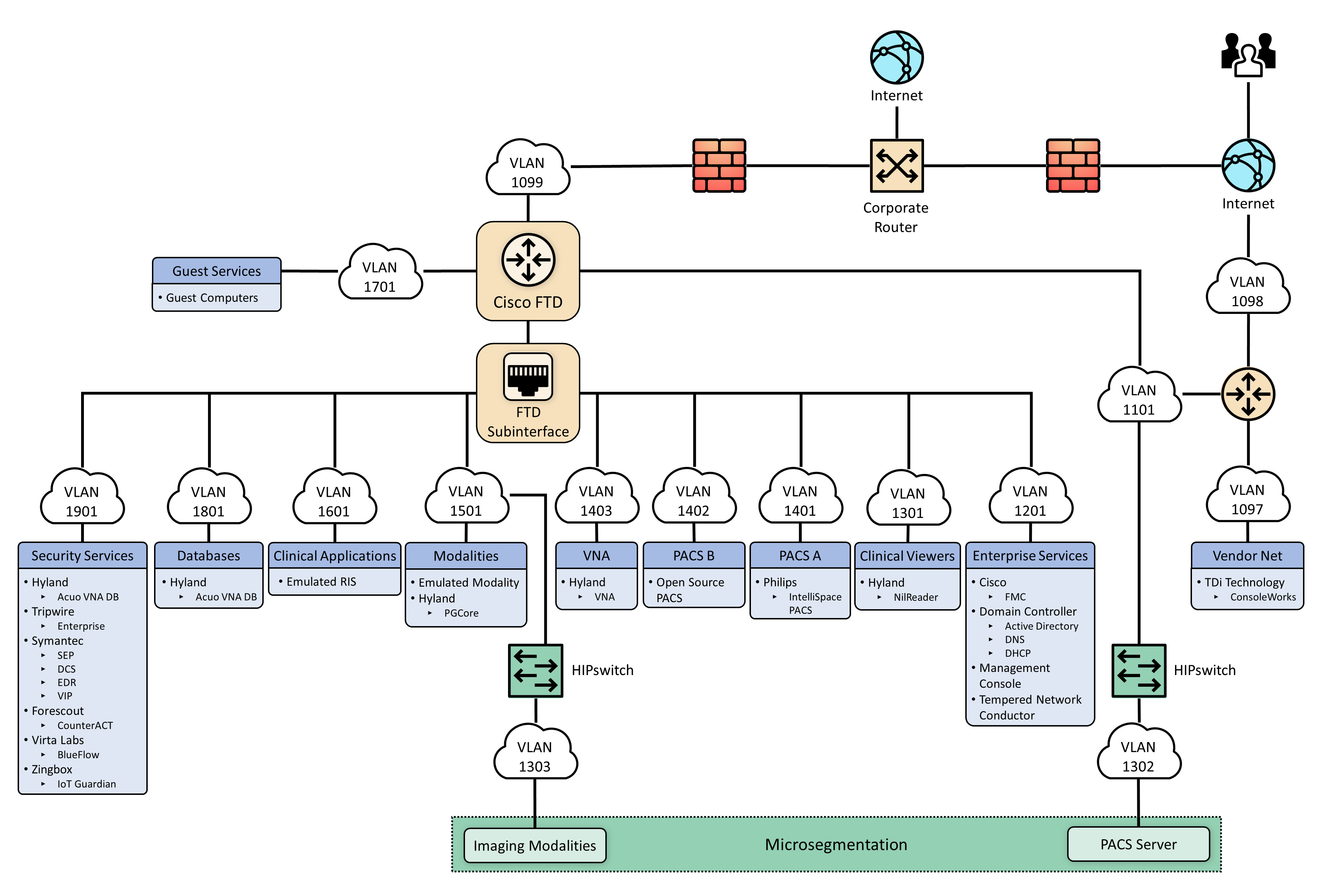
Figure 1‑1 depicts a reference network architecture, introduced in NIST SP 1800-24B, Section 4.2, Final Architecture, which defines groupings that translate to network segments or zones. The rationale behind segmentation and zoning is to limit trust between areas of the network. In considering a hospital infrastructure, the NCCoE identified devices and usage and grouped them by usage. The grouping facilitated network zone identification. Once zones are defined, infrastructure components may be configured so that those zones do not inherently have network access to other zones within the hospital network infrastructure. Segmenting the network in this fashion limits the overall attack surface posed to the PACS environment and considers the network infrastructure configuration as part of an overall defense-in-depth strategy.
Figure 1‑1 PACS Final Architecture
2 Product Installation Guides
This section of the practice guide contains detailed instructions for installing and configuring the products that the NCCoE used to build an instance of the example solution.
The project implemented security capabilities across the laboratory infrastructure to safeguard the emulated modalities, emulated RIS, viewer workstations, and PACS and VNA systems. Security control products that align with capabilities were implemented for the environment. Products that align with the security capabilities are enumerated in NIST 1800-24B, Section 3.6, Technologies, Table 3-5.
2.1 Picture Archiving and Communication System (PACS)
This project implemented two separate PACS: Philips IntelliSpace solution and an open-source PACS (DCM4CHEE). These PACS emulate the case where a healthcare delivery organization (HDO) may have different PACS vendors installed in its environment.
2.1.1 Philips IntelliSpace PACS
The project implemented the Philips IntelliSpace PACS solution as a central component to the lab build. IntelliSpace includes several common features, such as the ability to integrate Digital Imaging and Communications in Medicine (DICOM) and non-DICOM images and allowed the project team to emulate common medical-imaging workflow processes. The project deploys an IntelliSpace instance to receive images from an open-source modality emulator tool, which allows the project to simulate working HDO environments. The project integrates IntelliSpace with the Hyland VNA solution also installed in the lab.
System Requirements
The Philips IntelliSpace system consists of several components installed on different VMware virtual machines (VMs). Table 2‑1 depicts base configuration requirements to construct the IntelliSpace VMs.
Table 2‑1 Base VM Configuration Requirements
VM Name |
Description |
Central Processing Unit (CPU) |
Memory |
Storage |
Operating System |
Software |
|---|---|---|---|---|---|---|
DC1 |
Domain Controller (DC) |
4 |
8 gigabytes (GB) of random access memory (RAM) |
200 GB |
Microsoft Windows Server 2012 |
Microsoft Structured Query Language (SQL) 2012, Internet Information Services (IIS) 7 |
IntelliSpace Server |
Infrastructure, Integration, Rhapsody Health Level 7 (HL7), DICOM processor, SQL Database (DB), Anywhere Viewer (web client) |
4 |
8 GB RAM |
200 GB |
Microsoft Windows Server 2012 |
Microsoft SQL 2012, IIS 7 |
Universal Data Manager (UDM) |
UDM, WEB DICOM services Image Lifecycle Management Image pre-fetching from VNA |
4 |
8 GB RAM |
200 GB |
Microsoft Windows Server 2012 |
Microsoft SQL 2012, IIS 7 |
IntelliSpace PACS Client Installation
The project team collaborated with a team of Philips Healthcare deployment engineers to install the environment. Based on the base VM configuration requirements, the NCCoE team created the VMs by using the open virtualization format (OVF) files provided by Philips Healthcare. Philips engineers deployed the applications on the VMs and created instances for DC1, IntelliSpace server, and UDM, as noted in Table 2‑1. VM instances were deployed on respective servers.
IntelliSpace PACS is a web-based distributed system. Clinicians, referring physicians, nurses, or bioengineers use web-based client applications on workstations to view, analyze, and qualify medical images. Once the server components were installed, the web-based client installation was performed using the following procedures:
Open Internet Explorer from a workstation and assign the IntelliSpace server with the internet protocol (IP) address 192.168.140.131. Enter the IntelliSpace server IP address in the address bar by using the following uniform resource locator (URL): https://192.168.140.131/clientweb/installers.
Select IntelliSpacePACSEnterpriseSetup.exe under the Standalone Installers bullet list of available IntelliSpace PACS Installers screen to start the installation.

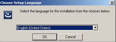
An option to choose setup language displays. Select the English (United States) from the drop-down and click OK.
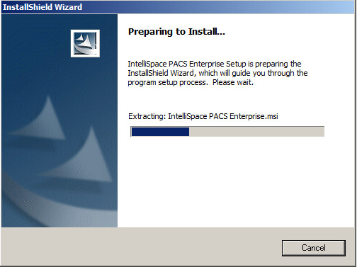
After the setup language has been set, the InstallShield Wizard begins the installation process.
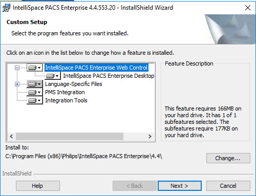
Use the default setting for the Custom Setup and click the Next > button that appears at the bottom of this window.
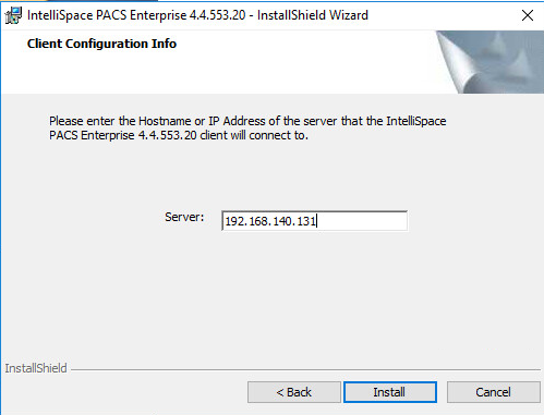
On the Client Configuration Info window, enter 192.168.140.131 as the Server IP address, and click Install.
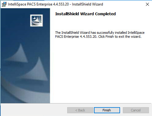
When installation is finished, the InstallShield Wizard provides a message indicating successful installation. Click Finish.
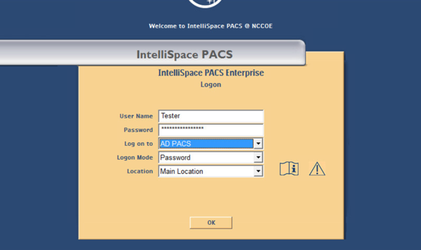
Once the installation is done, the installer places an IntelliSpace PACS Enterprise icon on the desktop. Type Tester in the User Name field and the corresponding password in the Password field, then click OK to log in.
When the program launches, the default page launches the Patient Lookup screen.
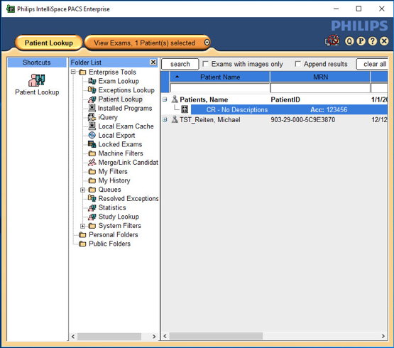
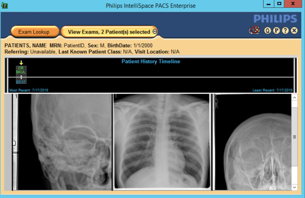
To view an exam, navigate to Exam Lookup, which lists a summary of a patient’s exams. Double-click an exam in the list. If the exam has an image, it will be displayed. An example is below.
IntelliSpace PACS Client Configuration
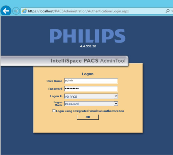
Philips Deployment Engineers accomplished deployment and configuration by using PowerCLI and scripts. Other basic configurations can be implemented through the administration web page provided by the IntelliSpace PACS by using the URL https://192.168.140.131/PACSAdministration.
Enter the admin as the User Name, enter the proper Password, select AD PACS from the Logon to drop-down list, select Password from the Logon Mode, then click OK.
On the admin home page, add a new user by navigating to Security, found on the far-left column of the Common Tasks screen. Click Users, then click Add a New User.
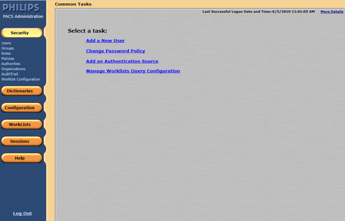
To add a new user, navigate to SECURITY, found on the far-left column of the Common Tasks screen, and click Users.
Enter the User ID.
Enter the user’s First Name.
Enter the user’s Middle Name (optional).
Enter the user’s Last Name.
Enter the user’s Email Address (optional).
Assign an IntelliSpace PACS AdminTool Password for the user (required). Enter the password again to confirm it.
Configure Sources for User Authentication
IntelliSpace supports either a locally hosted or an external authentication source. An authentication source provides a directory structure that authenticates and manages user and group accounts. The internal authentication source, called iSite, implements a local DB of users and groups. IntelliSpace also supports a lightweight directory access protocol (LDAP) server connected to a Microsoft Active Directory (AD). The external user authentication is used as the configuration source. The following steps describe how to create an LDAP authentication source:
From the navigation bar, click the Security button, then click Authorities.
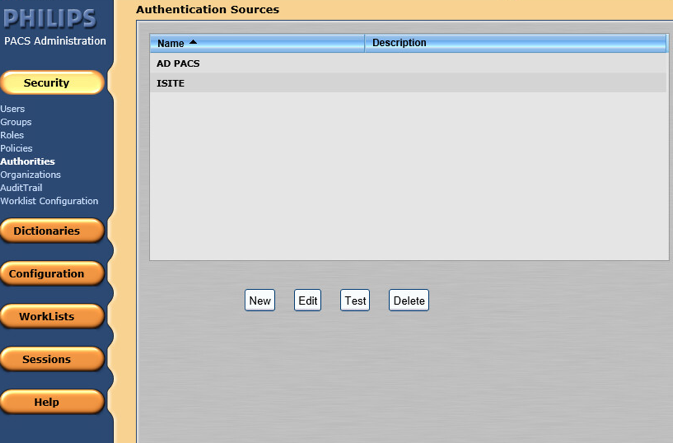
Click New to open the External Authentication Source wizard.
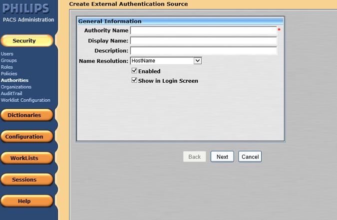
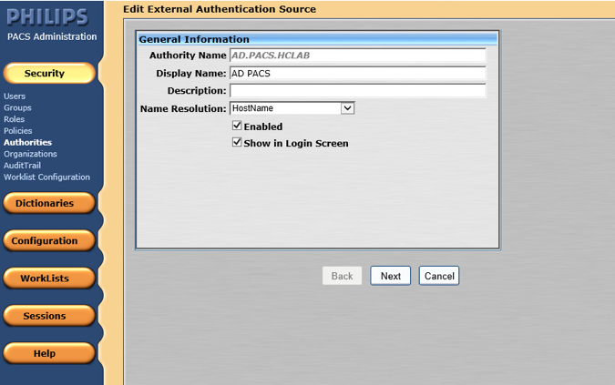
On the External Authentication Source page, set the following values, then click Next.
Set Authority Name to AD.PACS.HCLAB.
Set the Display Name to AD PACS.
Select HostName for Name Resolution.
Check the box next to Enabled.
Check the box next to Show in Login Screen.
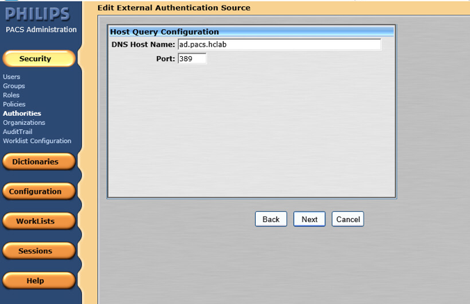
In the Advanced Directory Configuration, set DNS Host Name as ad.pacs.hclab and Port as 389.
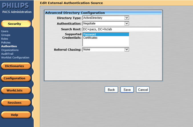
Navigate to the Edit External Authentication Source screen. In this project, the Directory Type is ActiveDirectory, and the Supported Credentials is Password. Click Save to save the settings.
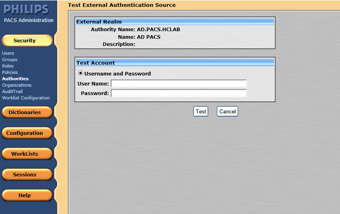
The interface provides a test feature to allow engineers to determine connectivity with the external authentication source. From the navigation bar, select Security > Authorities. Click the name of the External Authentication Source, and click Test.
Configure Connection to Modality Emulator
We used the open-source DVTk Modality Emulator as a modality for testing the communication between IntelliSpace PACS and a modality. Installation of the DVTk Modality Emulator can be found in Section 2.4.1. The following procedures configure several components. These components include the Radiology information system (RIS), modality performed procedure step manager (MPPS manager), and PACS/Workstation systems storage.
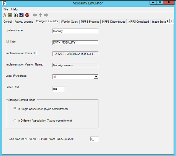
From the DVTk Modality application, click the Configure Emulator tab to set up a proper System Name, e.g., Modality; an application entity title (AE Title), e.g., DVTK_MODALITY; and a communication Listen Port, e.g., 104 for the emulator itself.
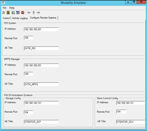
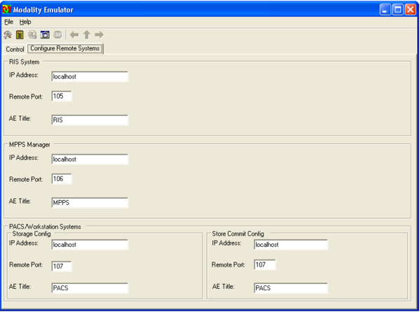
From the DVTk Modality application, click the Remote Systems tab to configure the remote systems, including RIS System, MPPS Manager, and PACS/Workstation Systems. Information for each system’s IP address as well as the port number is needed. Particularly, the AE Title for the Philips IntelliSpace PACS is required for the AE Title field. These are the input values:
RIS System
IP Address: 192.168.160.201
Remote Port: 105
AE Title: DVTK_RIS
MPPS Manager
IP Address: 192.168.160.201
Remote Port: 108
AE Title: DVTK_MPPS
PACS/Workstation Systems–Storage Config
IP Address: 192.168.140.131
Remote Port: 104
AE Title: STENTOR_SCP
PACS/Workstation Systems–Storage Commit Config
IP Address: 192.168.140.131
Remote Port: 104
AE Title: STENTOR_SCU
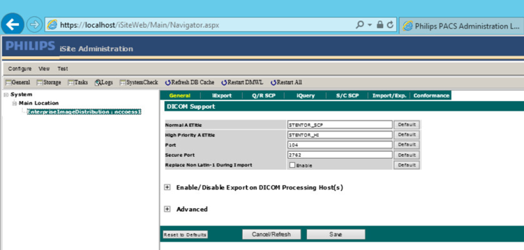
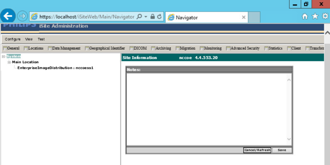
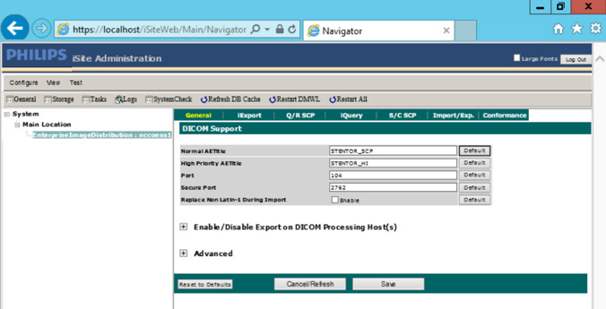
To configure the Philips IntelliSpace PACS AE Title and communication port, log on to the iSite Administration web site by using the URL https://192.168.140.131/iSiteWeb. Select Configure > DICOM > General, set the following values, and then click Save to save the settings.
Normal AE Title: STENTOR_SCP
High-Priority AE Title: STENTOR_HI
Port: 104
Secure Port: 2762
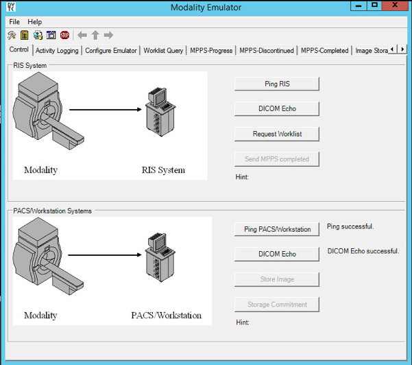
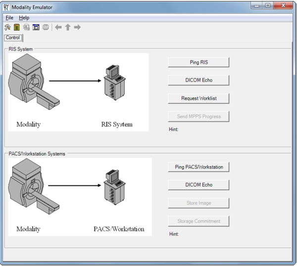
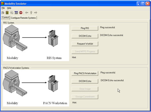
To test the connectivity, go to the DVTk Emulator application, then go to the Modality Emulator home page as shown below. Click the Ping PACS/Workstation and DICOM Echo buttons to verify the success of the pings. You should receive Ping Successful and DICOM Echo Successful messages.
Configure IntelliSpace PACS to Communicate with Hyland VNA
Refer to Section 2.2.2 for detailed installation guidance for Hyland VNA.
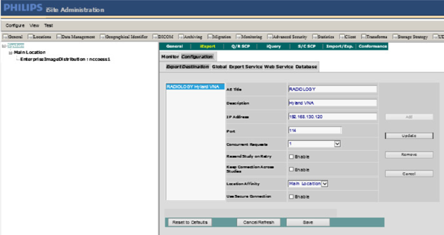
Obtain the Hyland VNA AE Title and port information for communication. Log in to the iSite Administration page by using the URL https://192.168.140.131/iSiteWeb.
From the Configure drop-down list, select DICOM to open the DICOM configuration page.
Fill in the known Hyland AE Title (e.g., RADIOLOGY), IP Address (e.g., 192.168.130.120), Port (e.g., 114), and other necessary information.
Log in to the IntelliSpace PACS Administration page by using https://192.168.140.131/PACSAdministration.
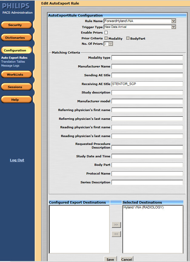
Click the Configuration button on the left panel to configure the Auto Export Rule.
Click the New button to create a new rule named ForwardHylandVNA.
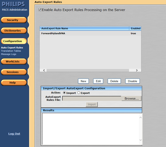
Set the Trigger Type as New Data Arrival.
Set the Receiving AE Title as Stentor_SCP, which is the AE Title for Philips IntelliSpace PACS.
Choose Hyland VNA (RADIOLOGY) from the Selected Destination box.
2.1.2 DCM4CHEE
DCM4CHEE is a collection of open-source applications that communicate with each other using DICOM and HL7 standards for clinical image management and archival. In this study, DCM4CHEE listens for connection requests from specific application entities like DVTk’s Modality Emulator to receive patient studies. DCM4CHEE will store these patient studies in a PostgreSQL DB and can archive these studies to the Hyland VNA. This build utilizes Docker to deploy the DCM4CHEE software.
System Requirements
CPUs: 2
Memory: 4 GB
Storage: 80 GB
Operating System: Ubuntu Linux 18.04
Network Adapter: VLAN 1402
Software: Docker
DCM4CHEE Installation
The guide for installing Docker on Ubuntu 18.04 can be found at [C1].
Go to https://github.com/dcm4che-dockerfiles/dcm4chee-arc-psql/tree/5.21.0 to download the software.
On the right-hand side of the page, click the Clone button to begin the file download.
Extract the downloaded content from the dcm4chee-arc-psql-5.21.0.zip file to a preferred directory.
Open a terminal with root privileges.
Navigate to the directory where the extracted content is located.
Run
docker-compose up.Open a web browser and navigate to https://localhost:8443/dcm4chee-arc/ui2.
DCM4CHEE to VNA Configuration
Click the dark blue menu dongle (
 ) on the left-hand side of the screen.
Select Configuration.
Select AE list.
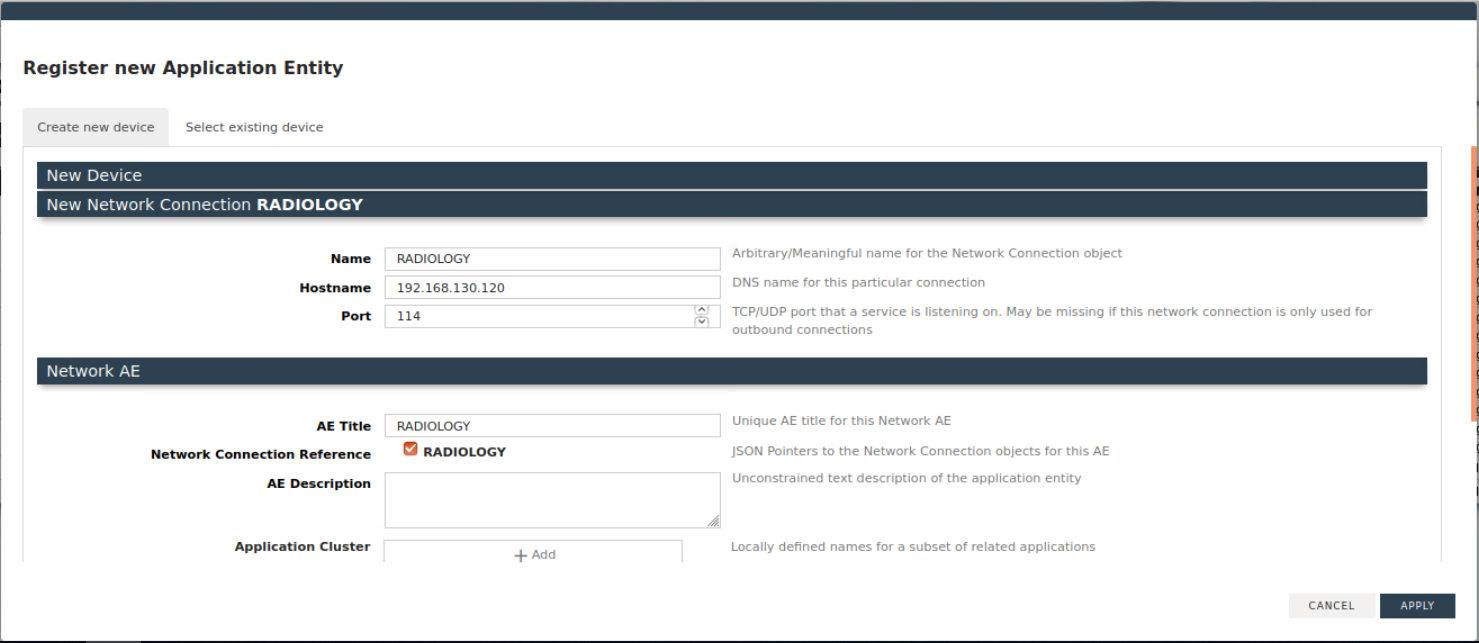
Click New AET, and provide the following information:
Name: RADIOLOGY
Hostname: 192.168.130.120
Port: 114
AE Title: RADIOLOGY
Click Apply.
DCM4CHEE to DVTk Modality Configuration
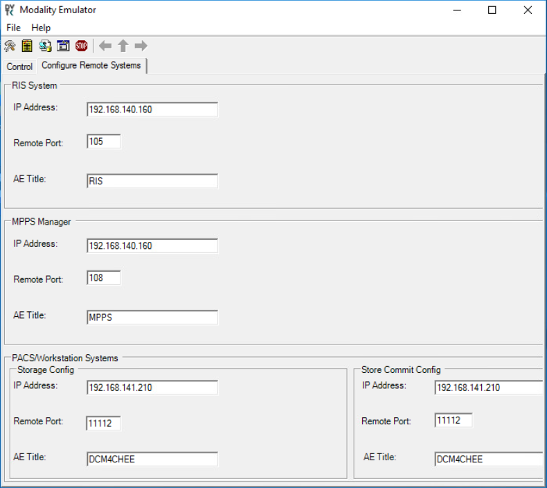
In the Modality Emulator, click the Configure Remote Systems tab at the top of the window.
Navigate to the PACS\Workstation Systems section, and input the information with the following values:
RIS System
IP Address: 192.168.140.160
Remote Port: 105
AE Title: RIS
MPPS Manager
IP Address: 192.168.140.160
Remote Port: 108
AE Title: MPPS
PACS/Workstation System–Storage Config
IP Address: 192.168.141.210
Remote Port: 11112
AE Title: PACS
PACS/Workstation System–Storage Commit Config
IP Address: 192.168.141.210
Remote Port: 11112
AE Title: PACS
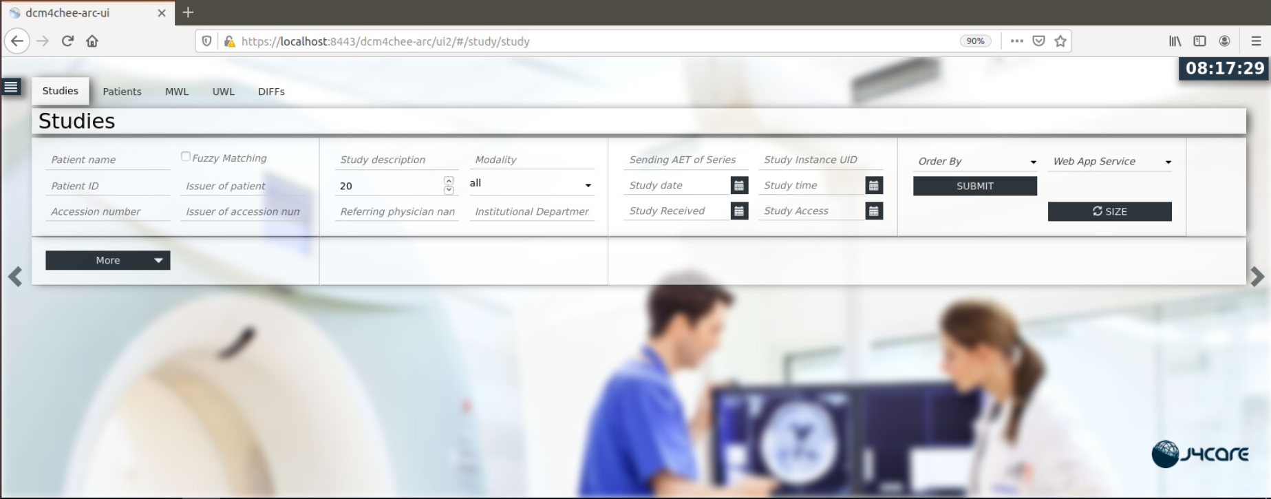
DCM4CHEE View Stored Data and Archive to VNA
Click the dark blue menu dongle (
) on the left-hand side of the screen.Select Navigation.
Select DCM4CHEE under Web App Service on the right-hand side of the screen.
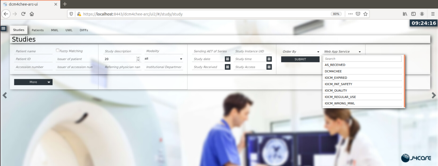
Select Submit to see stored patient studies.
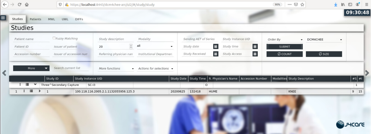
Click the dark blue ellipsis (
 ) on the left-hand side of the study on the second row.
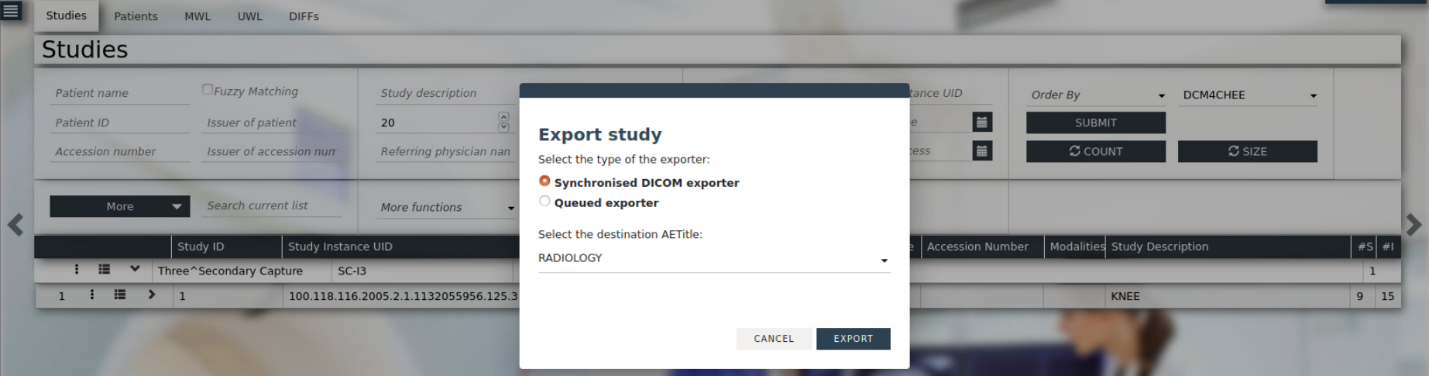
Click the Export (
 ) icon.
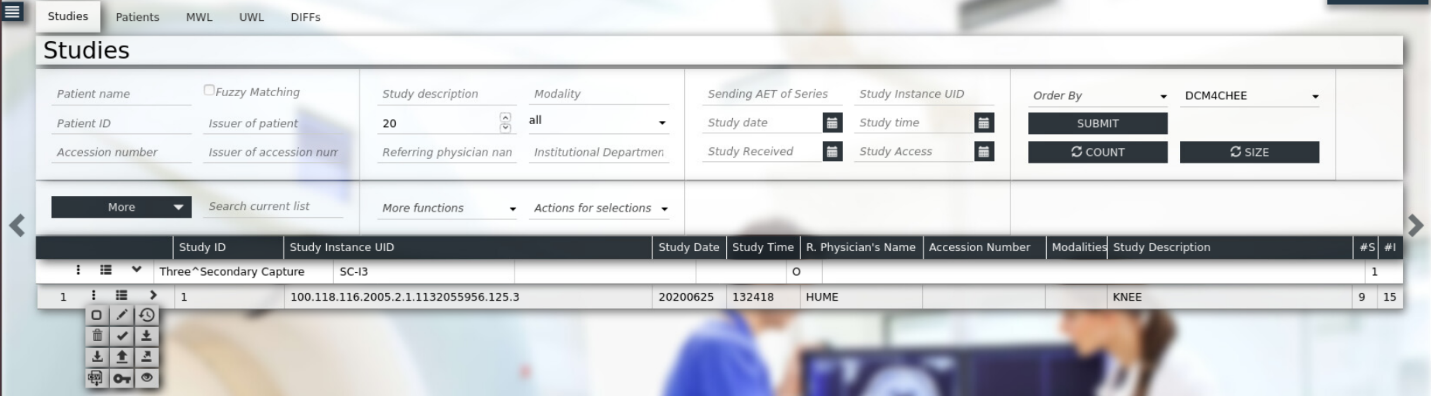
Select RADIOLOGY from the drop-down list.
Click Export.
2.2 VNA
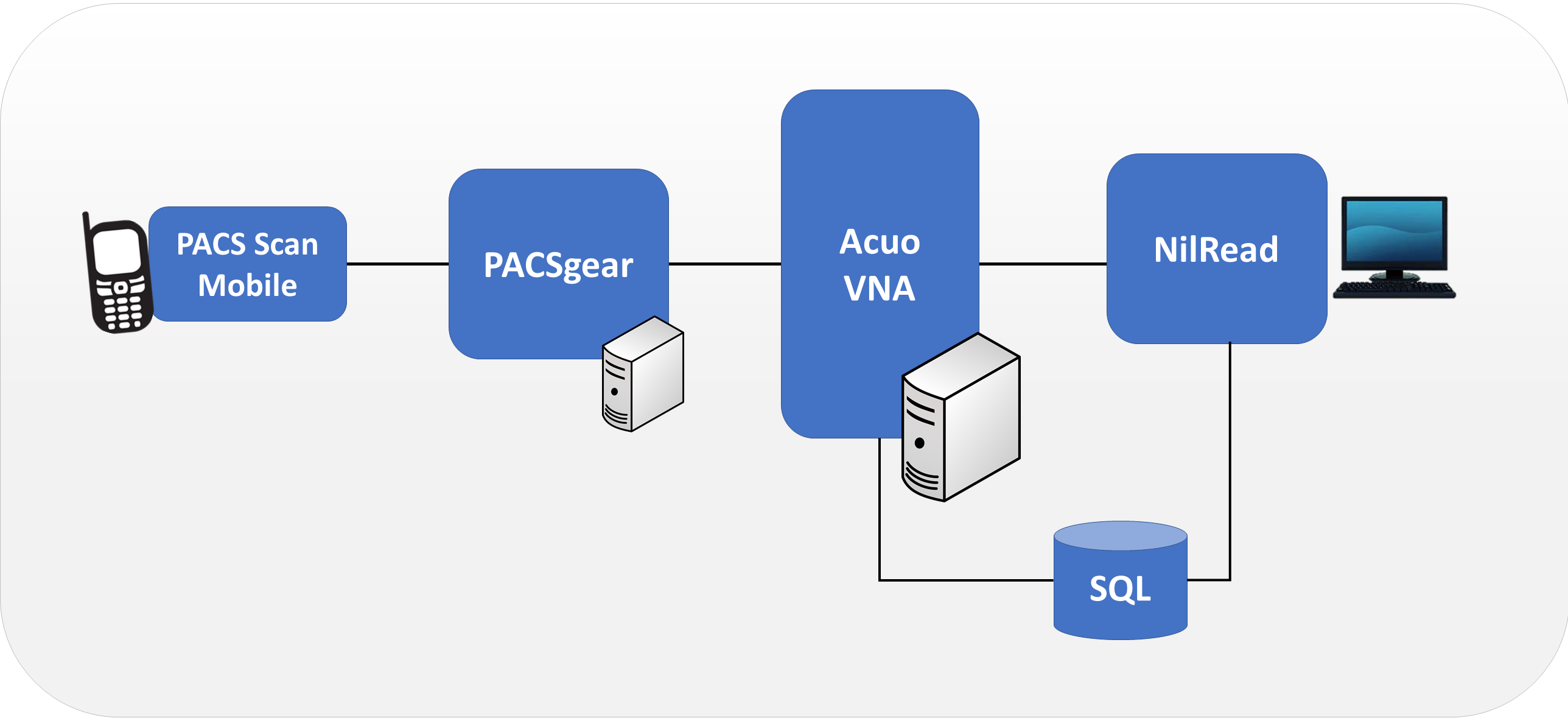
Hyland Acuo VNA features several different systems and applications, which include:
Acuo VNA: core application server with services used to store, track, and retrieve digital assets stored in an archive
PACSgear Core Server: image processing and routing server, and back-end services
PACS Scan Mobile/Web: mobile device image acquisition and file-import application
NilRead: enterprise image-viewing application
The diagram in Figure 2‑1 shows the connectivity between the Hyland Acuo VNA systems and applications.
Figure 2‑1 Hyland Systems and Applications Connectivity
Installation procedures for the above Hyland products are described in the sections that follow.
2.2.1 Hyland Database Server
Hyland Database Server supports operations for other Hyland products, including Hyland Acuo VNA and Hyland NilRead. The installation and configuration procedures can be found below:
System Requirements
CPUs: 4
Memory: 12 GB RAM
Storage:
Hard Drive (HD)1: 80 GB (operating system [OS] installation)
HD 2: 20 GB (DB drives)
HD 3: 10 GB (Tx logs)
Operating System: Microsoft Windows Server 2016
Network Adapter: VLAN 1801
Hyland Database Server Installation
Install the SQL Server 2017 according to the instructions detailed in Install SQL Server from the Installation Wizard (Setup) [C2].
Hyland Database Configuration
The installation creates default service accounts for each service. The project used these default service accounts. User and privileged login accounts were created for the Hyland application suite and linked to unique Microsoft domain users. The project created the PACS\AcuoServiceUser and PACS\Administrator accounts.
The project implemented Windows Authentication Mode for the SQL Server.
Application DB instances were created as needed automatically when product applications were installed.
This project implemented the following DB instances through the SQL Server Management Studio: AcuoMed, HUBDB, NILDB, and PGCORE.
The project also implemented instances for OPHTHALMOLOGY, RADIOLOGY, and WOUND_CARE.
2.2.2 Hyland Acuo VNA
Hyland Acuo VNA provides access to medical images and documents through interactions with a variety of different PACS, modalities, and image viewers. Acuo VNA also supports various standards, including HL7 and DICOM. The installation and configuration procedures can be found below.
System Requirements
CPUs: 6
Memory: 12 GB RAM
Storage:
HD 1: 80 GB (OS installation)
HD 2: 80 GB (Dilib cache drive)
HD 3: 500 GB (image cache drive) was installed
Operating System: Microsoft Windows Server 2016
Network Adapter: VLAN 1301
Hyland Acuo VNA Installation
In the NCCoE test environment, the Hyland Acuo VNA was installed on a VM preconfigured with the OS and network requirements provided by Hyland. Engineers supplied by Hyland performed the installation.
Upon completion of the installation, three Windows services were created: AcuoMed, AcuoAudit, and AcuoStore. AcuoMed is associated with a DICOM DB containing the patient, study, and series record information that describes the images physically present on the Acuo VNA archive system. The AcuoStore also has its own DB for storing information related to bulk storage of digital images and related data, including information about the shares and about the applications that use those shares.
The installation created a web application for the AcuoAdmin Portal, where a secure sockets layer (SSL) certificate signed by DigiCert was created and assigned to the application for hypertext transfer protocol secure (https) enforcement.
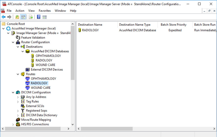
Hyland Acuo VNA Configuration
Hyland engineers performed configurations using the Microsoft MMC console and the AcuoAdmin Portal (https://192.168.130.120:8099/vnaweb/#1/home). The screenshots of the console management for these administration approaches are below:
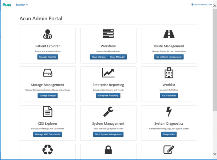
To verify successful completion of the VNA installation, the Hyland engineers launched the Acuo Administrator Portal application from the VNA server (local host). The Acuo Administrator Portal screen sample is below.
2.2.3 PACSgear Core Server
PACSgear Core Server is a capture and connectivity suite used to process DICOM and non-DICOM medical data, including patient demographics, images, videos, and HL7 messages. PACSgear Core Server can be accessed from a web browser to handle user accounts, security, and client connectivity configuration. Installation and configuration procedures are described below.
System Requirements
CPUs: 4
Memory: 8 GB RAM
Storage:
HD 1: 80 GB (OS installation)
HD 2: 170 GB (application)
Operating System: Microsoft Windows Server 2016
Network Adapter: VLAN 1501
PACSgear Core Server Installation
Hyland engineers installed the Hyland PACSgear Core Server as listed below:
Hyland engineers installed the PACSgear Core Server following their technical guidelines.
The installation created a web application for the PACSgear Core Portal, where an SSL certificate signed by DigiCert was created and assigned to the application for https enforcement.
PACSgear Core Server Configuration
The Hyland engineers configured the PACSgear Core Server. The basic configuration involves managing connection settings to external devices, lookup data sources, and event trace-managing departments for multitenancy architecture, and managing user access, among many more features. Each organization will configure the PACSgear based on its specific needs.
During the DB configuration, the Hyland engineers created instances for representative departments (e.g., ophthalmology, radiology, and departments that may see patients who need wound treatment).
Add New Departments: To add the ophthalmology department, complete the following steps:
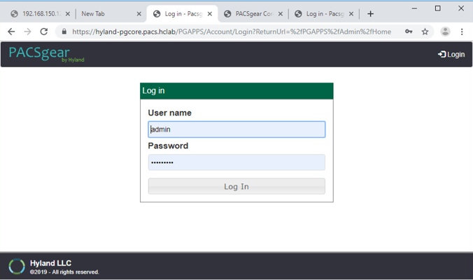
The Hyland engineers logged on to the PACSgear Admin portal by using https://hyland-pgcore.pacs.hclab/PGAPPS/Admin.
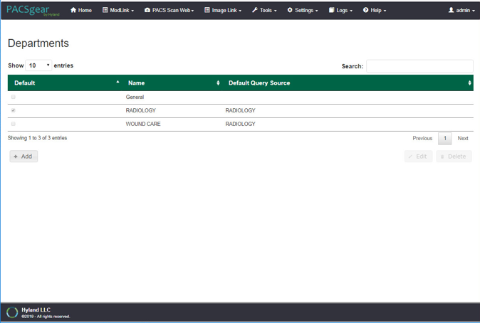
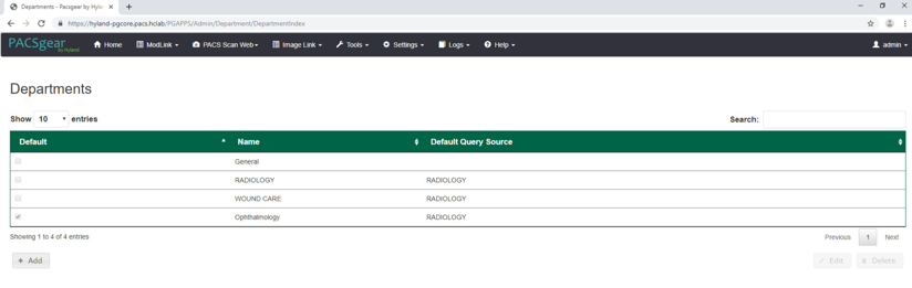
On the Settings menu, select Departments.
After selecting Departments from the Settings pull-down, the screen advances to a Departments screen. The Departments screen lists sample hospital departments created during the installation. The project then added a new department by clicking the + Add button.
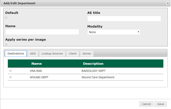
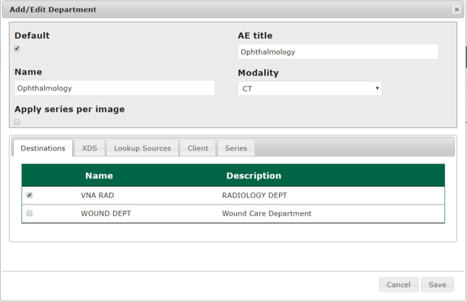
After clicking the + Add button, the Add/Edit Department screen opened and allowed the engineers to enter corresponding information.
In the Name text box, the engineers entered Ophthalmology to create a department that ties with the ophthalmology database instance created during DB configuration. Engineers also added the AE title as Ophthalmology and selected a CT Scan for the modality.
On the Destinations and Lookup Sources tabs, the engineers set up the destination and lookup sources for each department.
On the Client tab, the engineers set up the client access permissions to this department’s resources.
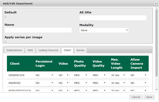
On the Series tab, click Add, type a description, click Save.
Verify that the department has been added to the list, based on what is displayed.
Add LDAP/Active Directory Server: To use an LDAP/Active Directory server, configure these parameters:
Create an LDAP_User account in Active Directory before proceeding.
Using a browser, log on to the PACSgear Admin portal by using https://hyland-pgcore.pacs.hclab/PGAPPS/Admin.
On the Settings menu, select Users.
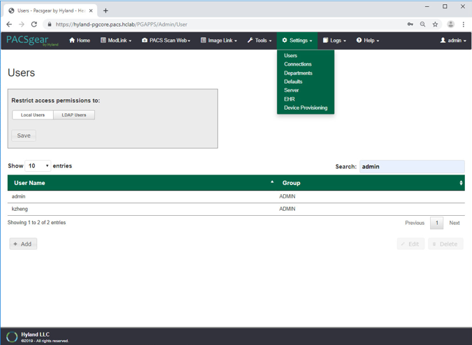
On the Users screen, navigate to Restrict access permissions to: and click the LDAP Users button. Enter 192.168.120.100 to populate the Server text box, and then enter pacs.hclab for Domain.
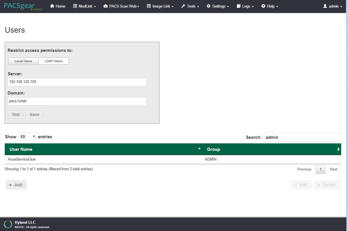
Click the Test button located under the Domain entry box.
Enter the LDAP_User credentials to verify connectivity to the AD.
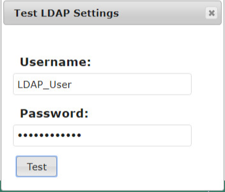
A message box displays indicating the test is successful. Click OK.

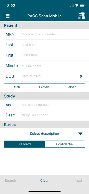
PACS Scan Mobile Configuration: Install and configure the PACS Scan application to an Apple iPhone by applying these steps:
On the iPhone, navigate to the App Store. Search for PACS Scan Mobile, from Perceptive Software. Perceptive Software is a Hyland business unit. Select the GET button to install the software, and then select the OPEN button. Select Allow to permit the software to send notifications.
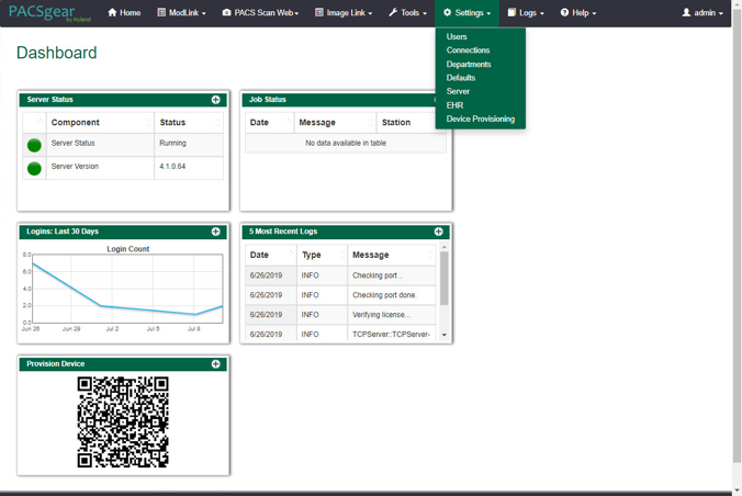
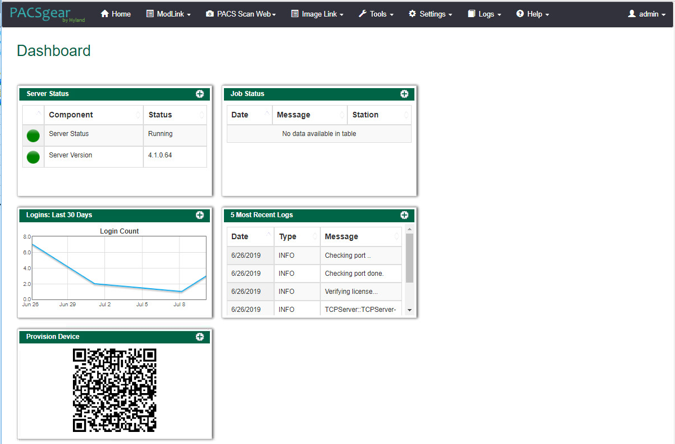
On a workstation, log in to PACSgear Core Server by using the administrator credentials; a dashboard displays and provide a Provision Device QR code.
On the mobile device PACS Scan App, tap the Quick Response (QR) code icon that appears under the Log In button. This turns on the built-in camera on the iPhone.
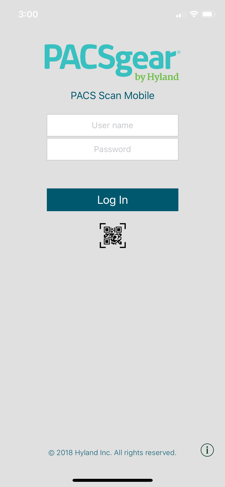
Point the camera at the QR code on the PC screen until a message box appears indicating Setting Updated Your settings have been updated. This setting configures the mobile PACS Scan application to the address of its PACSgear Core Server instance.
From a workstation, acquire the trusted root certificate from DigiCert. Further information for using DigiCert is described in Section 2.6.2.
Download the root certificate to the workstation local drive and attach the certificate as an email attachment sent to the installer.
The installer opens the email from the iPhone and double-clicks on the attachment to install the certificate to the device.
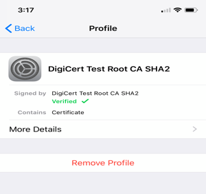
To verify the certificate installation, go to Settings > General > Profiles & Device Management to list all the certificate profiles.
Find the certificate you installed and click to display the detail. An example appears below:
To verify the PACS Scan Mobile App functionality, from the iPhone, double-click the PACS Scan App. The login page displays. Use an account and password that has been associated with a clinical department to log in. Successful login displays a patient information input page, as shown below:
2.2.4 Hyland NilRead
Hyland NilRead provides image access and viewing from various devices, including clinical viewing stations, tablets, and mobile devices. NilRead also provides image manipulation, interpretation, and collaboration across departments. The installation and configuration procedures are below.
System Requirements
CPUs: 6
Memory: 12 GB RAM
Storage:
HD 1: 80 GB (OS installation)
HD 2: 200 GB (web application)
HD 3: 100 GB (image cache)
Operating System: Microsoft Windows Server 2016
Network Adapter: VLAN 1301
Hyland NilRead Installation
Hyland engineers installed Hyland NilRead based on Hyland’s proprietary installation package and installation guides. NilRead has three services: Hub Front End service, Nil Back End service, and Nil Front End service. The Hub Front End service provides management service for multitenant configuration. The operation context is defined by the Nil DB content and includes user accounts, data life-cycle rules, hanging protocols, DICOM connectivity setup, and cached DICOM data index.
The installation created two web applications for the NilHub and NilRead Viewer, where SSL certificates signed by DigiCert were created and assigned to the applications for https enforcement.
Hyland NilRead Configuration
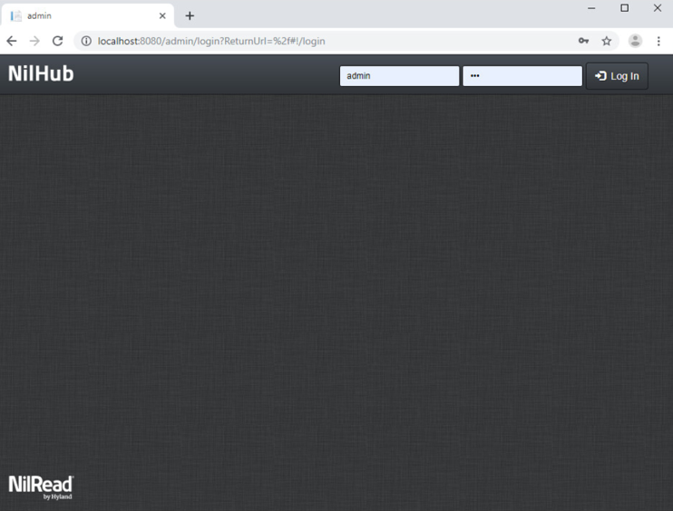
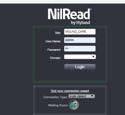
NilHub configuration is done from the NilHub web application. Launch a web browser from the NilHub server, and authenticate as admin, using the URL https://localhost:8080/, as follows:
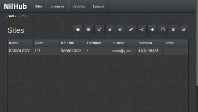
To add a new site from the NilHub home page, click the Sites tab in the top left-hand side of the screen.
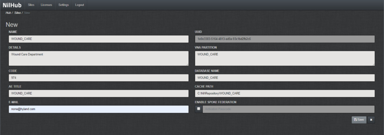
Click the + icon on the right-hand side of the screen to create a new site for the WOUND_CARE department, provide the information below, then click Save.
Name: WOUND_CARE
Details: Wound Care Department
Code: 974
AE Title: WOUND_CARE
VNA Partition: WOUND_CARE
Database Name: WOUND_CARE
Email: none@hyland.com
Log back in to NilHub specifying the WOUND_CARE Site in the top section of the login screen.
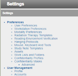
Click the Settings tab. Navigate to the User Management section and click Accounts.
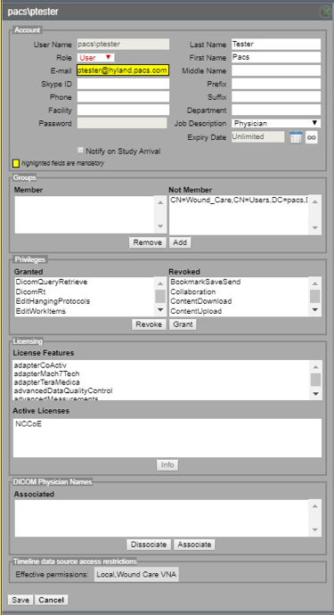
Click Add on the bottom left-hand side of the screen, and provide this information:
User Name: pacs\ptester
Last Name: Tester
First Name: Pacs
Role: User
E-Mail: ptester@hyland.pacs.com
Password: *****
Identify Member Groups to which the user needs access and click the Add button.
Specify the Granted Privileges that the user needs and click the Grant button.
Click the Save button on the bottom left-hand side of the screen.
Hyland engineers repeated the above steps to have multiple sites that accessed different VNA partitions/tenants, such as Radiology with access to all VNA tenants and Ophthalmology with access to only the Ophthalmology VNA partition/tenant.
2.3 Secure DICOM Communication Between PACS and VNA
Hyland Acuo VNA and Philips IntelliSpace PACS support DICOM Transport Layer Security (TLS). DICOM TLS provides a means to secure data in transit. This project implemented DICOM TLS between the Acuo VNA and IntelliSpace PACS via mutual authentication as part of the TLS handshake protocol [C3].
2.3.1 Public Key Infrastructure (PKI) Certificate Creation
Server/client digital certificates are created for the Hyland Acuo VNA and Philips IntelliSpace server. This project used DigiCert for certificate creation and management. The procedures that follow assume familiarity with DigiCert. Refer to Section 2.6.2 for further detail.
2.3.1.1 Create PKI Certificate for Hyland Acuo VNA
Use the DigiCert Certificate Utility for Windows to generate a certificate signing request (CSR) for Hyland Acuo VNA. Information needed for requesting the certificate for Hyland Acuo VAN is below:
Common Name: Hyland-VNA.pacs.hclab
Subject Alternative Name: Hyland-VNA.pacs.hclab
Organization: NIST
Department: NCCoE
City: Rockville
State: Maryland
Country: USA
Key Size: 2048
Submit the created CSR to DigiCert portal for certificate signing.
Download and save the signed certificate along with its root certificate authority (CA) certificate in the .pem file format.
Import the saved certificate to DigiCert Certificate Utility for Windows, then export the certificate with its private key in the .pfx format.
The certificate is ready for installation.
2.3.1.2 Create PKI Certificate for Philips IntelliSpace PACS
Use DigiCert Certificate Utility for Windows to generate a CSR for PACS server. Information needed for requesting the certificate is below:
Common Name: nccoess1.stnccoe.isyntax.net
Subject Alternative Name: nccoess1.stnccoe.isyntax.net
Organization: NIST
Department: NCCoE
City: Rockville
State: Maryland
Country: USA
Key Size: 2048
Submit the created CSR to DigiCert portal for certificate signing.
Download and save the signed certificate along with its root CA certificate in the .pem format.
Import the saved certificate to DigiCert Certificate Utility for Windows, then export the certificate with its private key in the .pfx format.
The certificate is ready for installation.
2.3.2 Public Key Infrastructure (PKI) Certification Installation
After creating the signed certificates for Acuo and IntelliSpace respectively, the certificates must be installed to the servers. The steps that follow describe how to install those certificates. Certificates must be applied for each server instance and assume access to both.
2.3.2.1 Install PKI Certificate for Hyland Acuo VNA
Install the certificate on Hyland Acuo VNA server by using the procedures below:
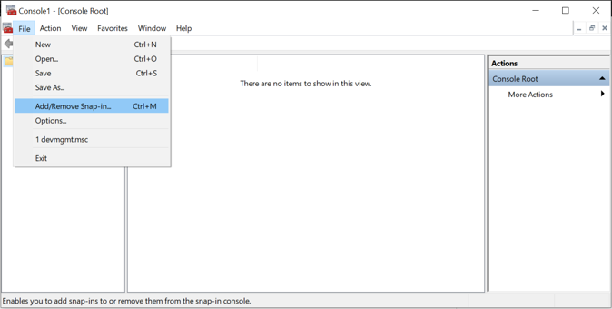
From the Acuo server, click Start > Run > mmc.
Select File > Add/Remove Snap-in…

Select Certificates and click Add.
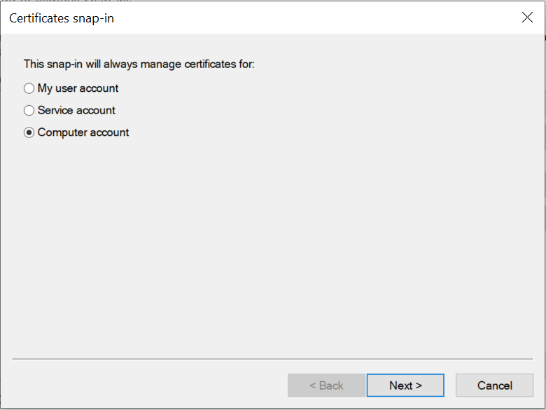
Choose Computer Account.
Choose Local Computer.
Click Finish, then click OK.
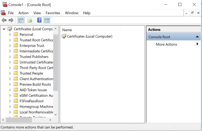
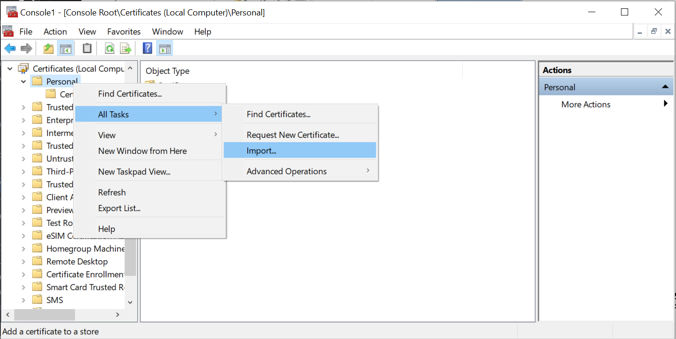
Once the snap-in has been added, navigate to Certificates (local computer)/Personal/Certificates.
Right-click and select All Tasks/Import.
Browse to the exported .pfx certificate.
Select the file and click Open.
Add the appropriate permissions to the newly generated certificate private key.
Navigate to Certificates > Personal > Certificates.
Right-click the certificate, select All Tasks > Manage Private Keys…
Add the AcuoServiceUser and grant full control permissions. Click OK.
This procedure also installs the signing root CA certificate (DigiCert Test Root CA SHA2) and its Intermediate Root certificate (DigiCert Test Intermediate Root CA SHA2) into the server computer.
2.3.2.2 Install PKI Certificate for Philips IntelliSpace PACS
Install the certificate on the PACS server by using the procedures that follow:
From the IntelliSpace server, click Start > Run > mmc.
Select File > Add/Remove Snap-in…
Select Certificates and click Add.
Choose Computer Account.
Choose Local Computer.
Click Finish; click OK.

Once the snap-in has been added, navigate to Certificates (local computer)/Personal/Certificates.
Right-click and select All Tasks/Import.
Browse to the exported .pfx certificate.
Select the file and click Open.
This procedure also installs the signing root CA certificate (DigiCert Test Root CA SHA2) and its Intermediate Root certificate (DigiCert Test Intermediate Root CA SHA2) into the server computer.
2.3.3 TLS Secure DICOM Configuration
With the signed certificates installed to the Acuo VNA and IntelliSpace PACS servers, proceed to configuring DICOM TLS. The procedures that follow describe TLS configuration that must be performed on both Acuo VNA and IntelliSpace PACS. This will enable DICOM TLS communications between these two end points, and secure data-in-transit communications bidirectionally between the VNA and PACS.
2.3.3.1 TLS Configuration for Hyland Acuo VNA
For receiving TLS DICOM messages from IntelliSpace PACS, configure a new service-class provider (SCP) in Acuo VNA using Microsoft Windows Console. Configuration is done from the Acuo VNA server.
Open Microsoft MMC to access the AcuoMed Image Manager (local):
From the Console > AcuoMed Image Manager (local) > DICOM Configuration, right-click Any IP Address > New SCP … to create a new service class provider (SCP) for TLS encryption.
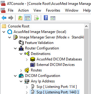
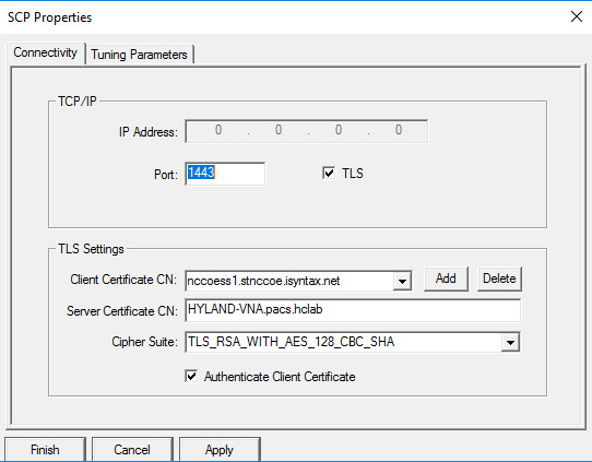
On the Connectivity tab of the SCP Properties page, provide the information below and click Add, Apply, then Finish:
Port: 1443
Check the TLS checkbox.
Client Certificate CN: nccoess1.stnccoe.issyntax.net
Server Certificate CN: HYLAND-VNA.pacs.hclab
Cipher Suite: TLS_RSA_WITH_AES_128_CBC_SHA
Check the Authenticate Client Certificate checkbox.
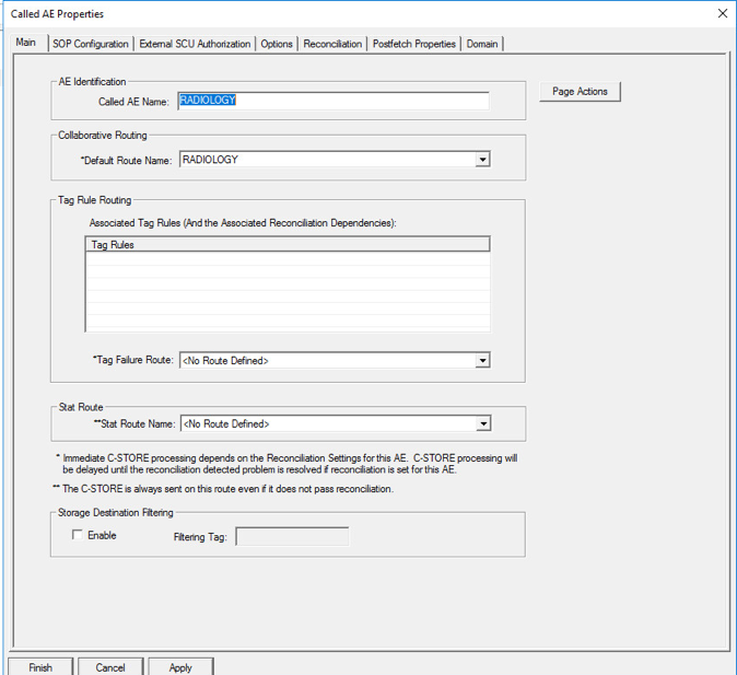
To add the Called AE to the SCP, right-click the created SCP [Listening Port:1443] and select New > Called AE … to open the AE Properties form.
Fill in the Called AE Name: e.g., RADIOLOGY; and Default Route Name: e.g., RADIOLOGY. After populating the information, click Add.
For sending a TLS DICOM message to IntelliSpace PACS, configure an External DICOM Device from the Acuo VNA by using Microsoft Windows Console.
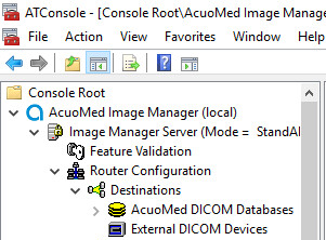
Open Microsoft MMC to access the Image Manager Server:
Navigate to Image Manager Server > Router Configuration > External DICOM Devices, right-click External DICOM Devices, and click New.
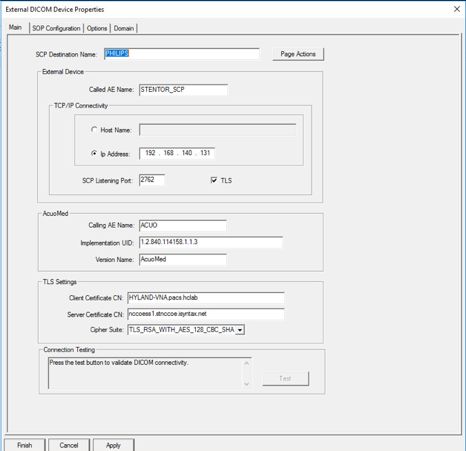
On the Main tab of the External DICOM Devices Properties page, provide the information below and click Apply, then click Finish:
SCP Destination Name: PHILIPS
Called AE Name: STENTOR_SCP
IP Address: 192.168.140.131
SCP Listening Port: 2762
Enable TLS by clicking the TLS checkbox next to the listening port number.
Called AE Name: ACUO
Implementation UID: 1.2.840.114158.1.1.3
Client Certificate CN: HYLAND-VNA.pacs.hclab
Server Certificate CN: nccoess1.stnccoe.isyntax.net
Cipher Suite: TLS_RSA_WITH_AES_128_CBC_SHA
Restart the AcuoMed service.
2.3.3.2 TLS Configuration for Philips IntelliSpace PACS
Next, configure TLS on the IntelliSpace PACS server. Take the steps below to enable this feature on the PACS:
Access the Philips iSite Administration web site https://192.168.140.131/iSiteWeb by using administrator credentials.
Click Configuration > DICOM to navigate to the DICOM configuration screen.
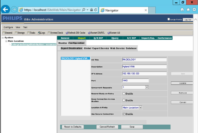
On the top menu, click iExport to open the iExport screen. Provide the information below, and click Save:
AE Title: RADIOLOGY
Description: Hyland VNA
IP Address: 192.168.130.120
Port: 1443
Use Secure Connection: checked
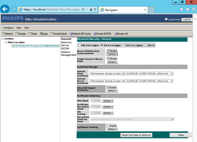
Click Configuration > Advanced Security, and make these selections:
TLS 1.0 or higher: Selected
Enable Secure Web Services Communication.
Enable Image Access in Secure Mode.
Default Client Certificate: CN= nccoess1.stnccoe.isyntax.net
Default Server Certificate: CN=HYLAND-VNA.pacs.hclab
Click Save to save the settings.
On the iSite Administration screen, click Next, and click Next again to open the page that follows:
Enable Validate Client Certificate for DICOM.
Enable Validate Server Certificate for DICOM.
Click Save to save the settings.
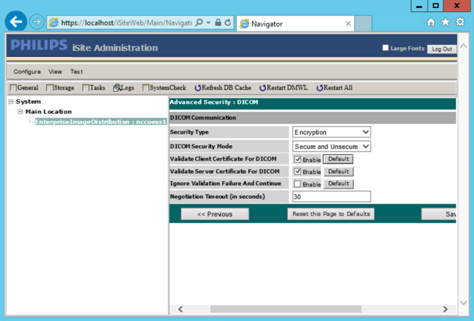
Restart the iSite Monitor Service.
2.3.4 PACS and VNA TLS Integration Tests
After implementing the above PKI-certification installation and TLS-enabling configuration, the Acuo VNA and IntelliSpace PACS servers are ready to perform the TLS secure DICOM communication tests. The secure DICOM communication tests were conducted for bidirectional data exchanges between Acuo VNA and IntelliSpace PACS to confirm:
DICOM communication is still functional.
DICOM communication is encrypted.
The test proves the DICOM communication was successful, with the accurate data exchange between the Acuo VNA and IntelliSpace PACS.
The network flow and dataflows monitoring tool indicate that the mutual authentication between Acuo VNA and IntelliSpace PACS is established. Encrypted application data were exchanged.
2.4 Modalities
Modalities represent medical devices used to capture medical images. The build did not implement physical devices but rather used virtualized or simulated modalities to source image files. The RIS was also emulated using open-source tools.
2.4.1 DVTk Modality Emulator
DVTk Modality is a modality emulator that can emulate all the DICOM functions of a modality system. It can simulate a real modality to test and verify communication with all the DICOM services. It uses DICOM files as input for queries, MPPS, and storage actions. Consequently, this project used the DVTk Modality as an emulator to test the connectivity, communication, workflow, and interaction between PACS and modality in the lab.
System Requirements
Operating System: Microsoft Windows 7 (with Microsoft .NET 4.0 Framework)
Network Adapter: VLAN 1402
DVTk Modality Installation
Download the installation software from the DVTK site [C4].
Click the Modality Installation file (e.g., DVTk-Modality-Emulator-5.0.0.msi) to start the installation process.
Follow the wizard instructions to continue the installation until it successfully completes.
Close the installation window.
The DVTk Modality Emulator can be launched from the PC Start menu. The Modality Emulator interface is below.
DVTk Modality Configuration
Configuration of the DVTk Modality involves configuration of the communications with different external systems, including the RIS, which is the worklist provider or a work-list broker connected to the RIS; the MPPS manager that handles the MPPS messages for status reporting; and the PACS and its DB where the images will be stored. The information needed for these external systems should include the correct IP address, Port number, and Application Entity Title (AE Title). Input the information with these values:
RIS System
IP Address: 192.168.160.201
Remote Port: 105
AE Title: RIS
MPPS Manager
IP Address: localhost
Remote Port: 105
AE Title: RIS
PACS/Workstation Systems–Storage Config
IP Address: localhost
Remote Port: 106
AE Title: MPPS
PACS/Workstation Systems–Storage Commit Config
IP Address: localhost
Remote Port: 107
AE Title: PACS
Store Commit Config
IP Address: localhost
Remote Port: 107
AE Title: PACS
The configuration of the modality itself is also needed to indicate its AE Title (e.g., DVTK_MODALITY), Local IP Address (e.g., 172.31.138.126), and Listen Port (e.g., 104) to be paired for association negation with other remote systems. The screenshot that follows indicates the options for the Modality Emulator configuration:
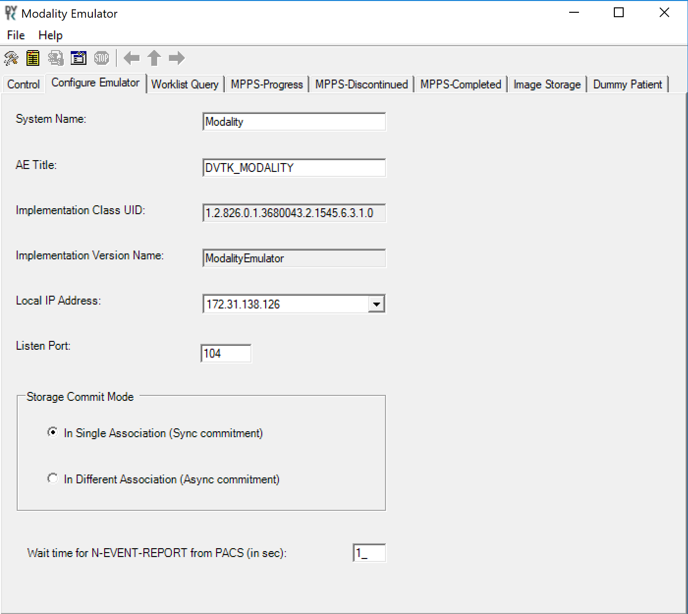
Several tabs exist for configuring the behavior of the emulator. They can be configured as needed or by using the default settings. Once the configuration is done, the emulator front graphical user interface (GUI) provides some test buttons for verifying the connectivity, including RIS System and PACS/Workstation Systems server Internet Control Message Protocol pings and DICOM echo:
2.4.2 DVTk RIS Emulator
DVTk, the Health Validation Toolkit, is an open-source software. The DVTk RIS Emulator is an application that handles Modality Worklist and Modality Performance Procedure Step requests from remote applications and then responds with the emulated results using the DICOM files specified by the users.
System Requirements
Operating System: Microsoft Windows 7 (Microsoft .NET Framework 2.0)
DVTk RIS Emulator Installation
Download the DVTk RIS Software installer RIS Emulator .msi file from http://www.dvtk.org.
Start the installation procedure by double-clicking the .msi installation file.
Follow the wizard screen instructions to continue the installation until the end of successful installation displays.
- Close the installation window and start the RIS Emulator. The user interface of the RIS Emulator tool that follows is shown with the tabs that
follow for selecting the modes:
Worklist
MPPS
Edit DCM Files
Activity Logging
Results
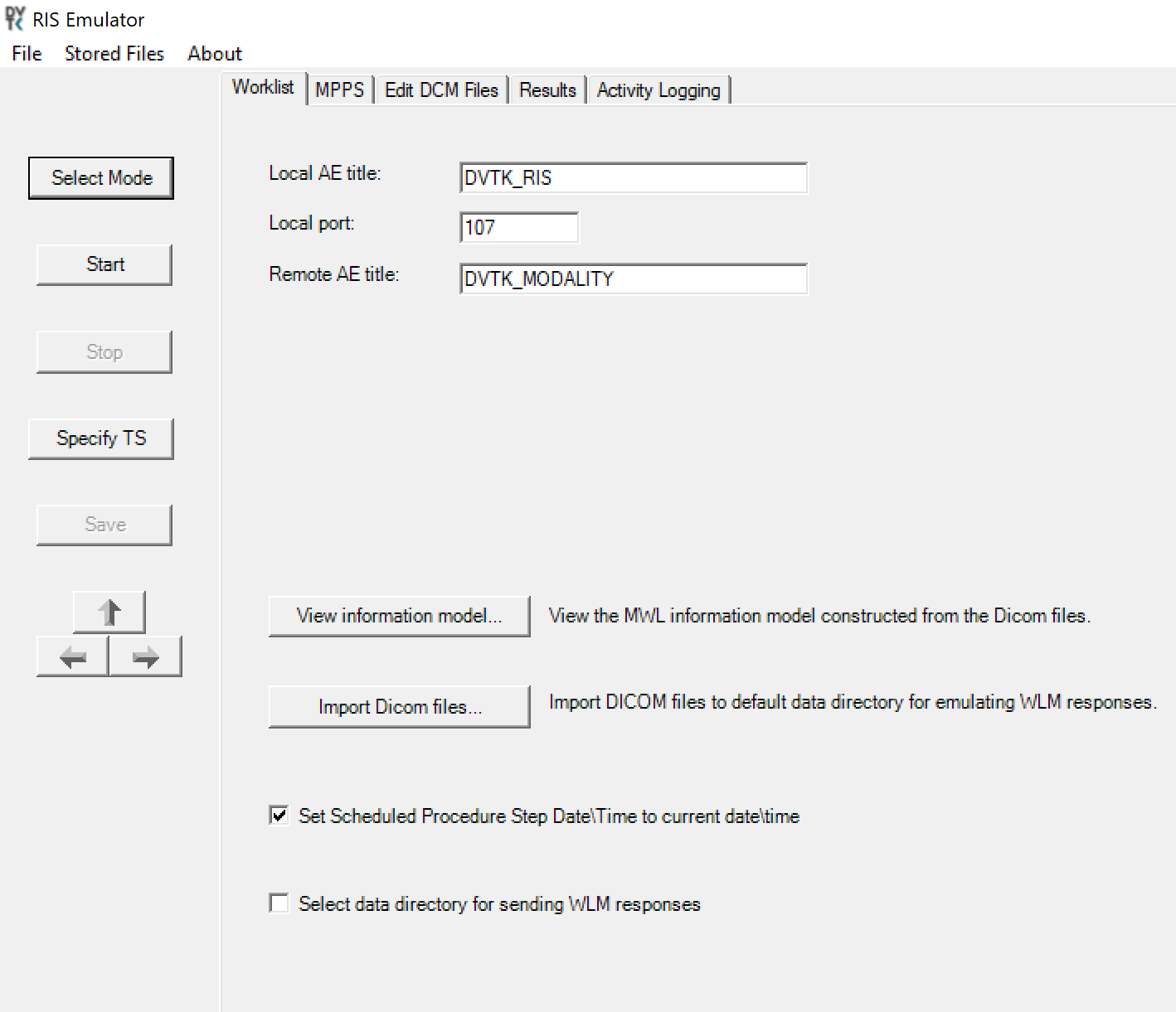
DVTk RIS Emulator Configuration
Worklist Configuration
Local AE title: AE title of the RIS Emulator
Local Port: the port of the RIS Emulator for incoming association
Remote AE title: AE title for the service-class user paired with the RIS Emulator
View Information Model: information model used for sending the emulator response; default value is taken
Select Data Directory for sending WLM responses: location for storing the emulated responses to the Worklist requests. A default setting can be used, which is C:\Progam Files\DVTk\RIS Emulator\Data\Worklist\
The RIS Emulator also supports other parameter configurations such as MPPS and Store Files functionality. These can be done as needed.
Configuration of the RIS Emulator and the modality storage emulator should be done accordingly so they can communicate with each other.
2.5 Asset and Risk Management
The build includes commercially available tools used to implement asset and risk management for medical devices. The implemented tool provides an asset inventory of medical devices that are identified via NetFlow traffic data. The tool also automates vulnerability detection and depicts a risk score. In addition to modality devices, we used other tools to manage server components.
2.5.1 Virta Labs BlueFlow
Virta Labs BlueFlow is a medical asset management software that allows discovery and management of medical devices on the network. This project used BlueFlow to create an organized inventory of the medical devices in the PACS architecture.
System Requirements
CPUs: 2
Memory: 8 GB RAM
Storage: 100 GB (thin provision)
Operating System: CentOS 7
Network Adapter: VLAN 1201
Virta Labs BlueFlow Installation
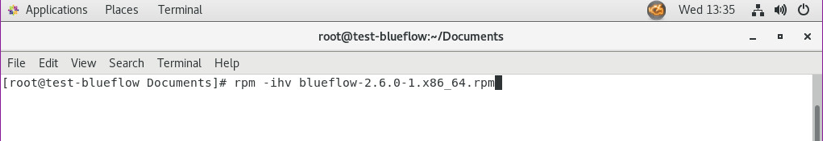
Run
rpm -ihv blueflow-2.6.0-1.x86_64.rpmin the CentOS 7 terminal.Wait for the package installation process to complete.
Depending on your environment, you may need to install some dependencies before the BlueFlow package can be successfully installed.
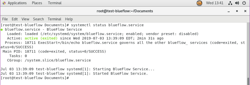
Run
sysyemctl status blueflow.servicein the CentOS 7 terminal.Ensure blueflow.service is active.
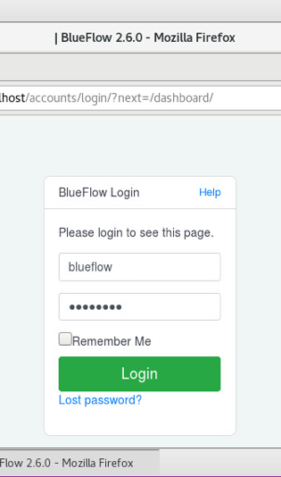
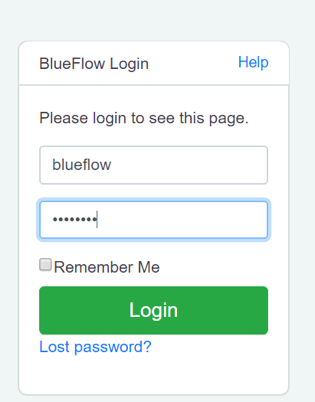
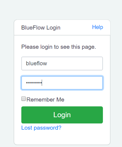
Visit https://localhost to verify that BlueFlow web service is operating as expected, with a BlueFlow Login page.
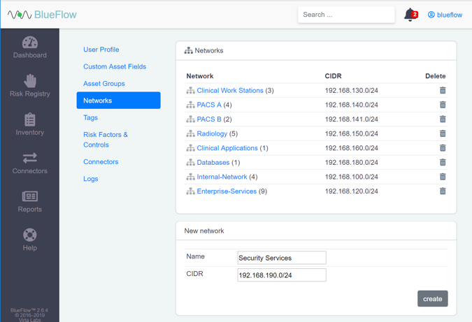
Virta Labs BlueFlow Network Groups Configuration
Log in to the BlueFlow web console.
Navigate to the Inventory tab.
Under the Networks section, click the gear icon.
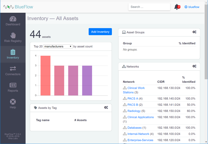
Enter Security Service as a Name for the new network group.
Enter 192.168.190.0/24 as a classless inter-domain routing (CIDR) for the new network group.
Click create.
Verify that the new network group (Security Services) has been created.
Click the name of the new network group.
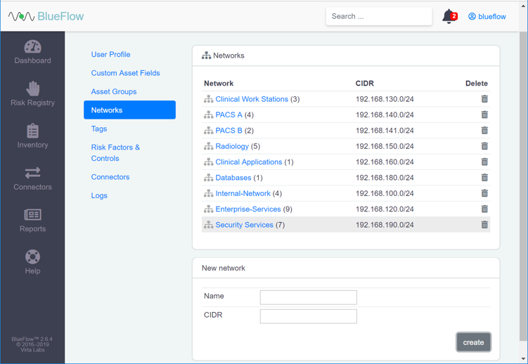
Assets will be listed on this page if they match the network group’s criteria.
If there are no assets currently listed, you can manually add them by navigating to Inventory > Add Inventory or by running an IP discovery scan (detailed in the next section).

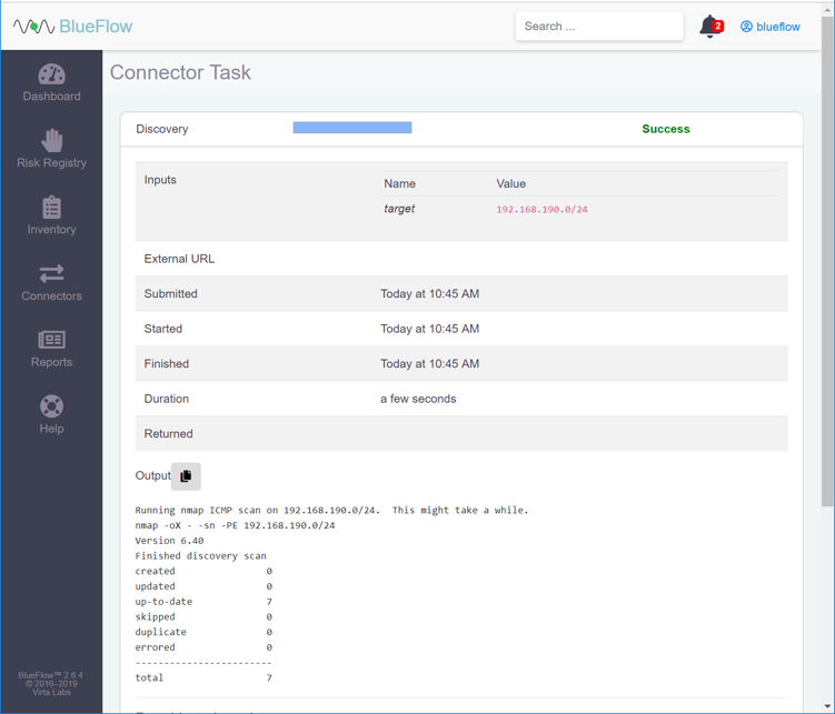
Running an IP Discovery Scan in Virta Labs BlueFlow
Log in to the BlueFlow web console.
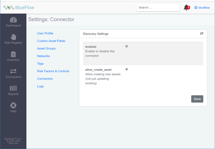
Navigate to Connectors > Discovery.
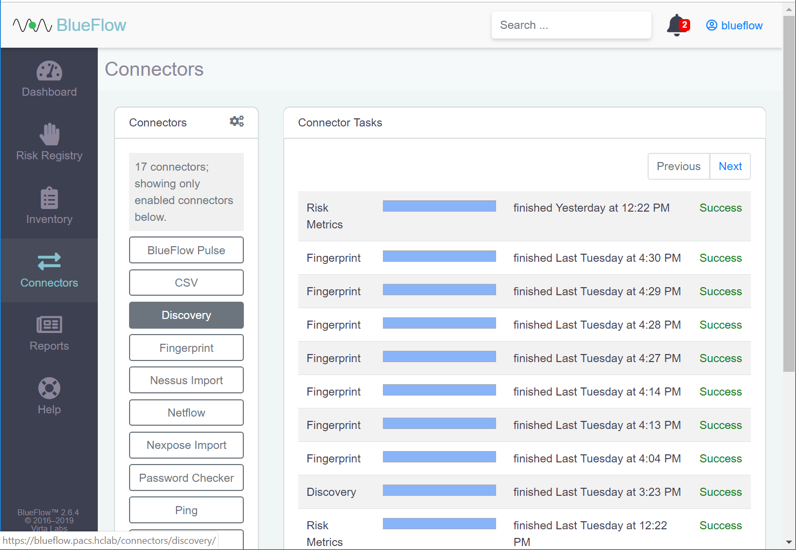
Under Discovery, click the gear icon.
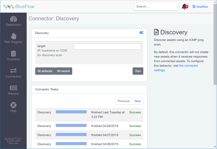
Check the box next to allow_create_asset.
Click Save.
Enter an IP (e.g., 192.168.190.0/24), host name, or CIDR that you would like to scan.
Click Run.
Wait for the discovery scan to finish.
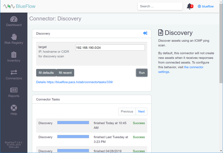
Click the row of the completed scan to view more details.
Note: From this page, you can view the output of the scan, including how many devices were discovered within the provided network range.
2.5.2 Tripwire Enterprise
Tripwire Enterprise is a security configuration management software that monitors file integrity through software-based agents. For this project, we used Tripwire Enterprise to monitor file changes on PACS servers and the VNA DB.
System Requirements
CPU: 1
Memory: 4 GB RAM
Storage: 120 GB (thin provision)
Operating System: Microsoft Windows Server 2016
Network Adapter: VLAN 1201
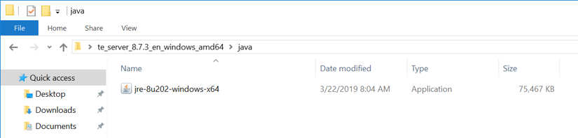
Tripwire Enterprise Console Installation
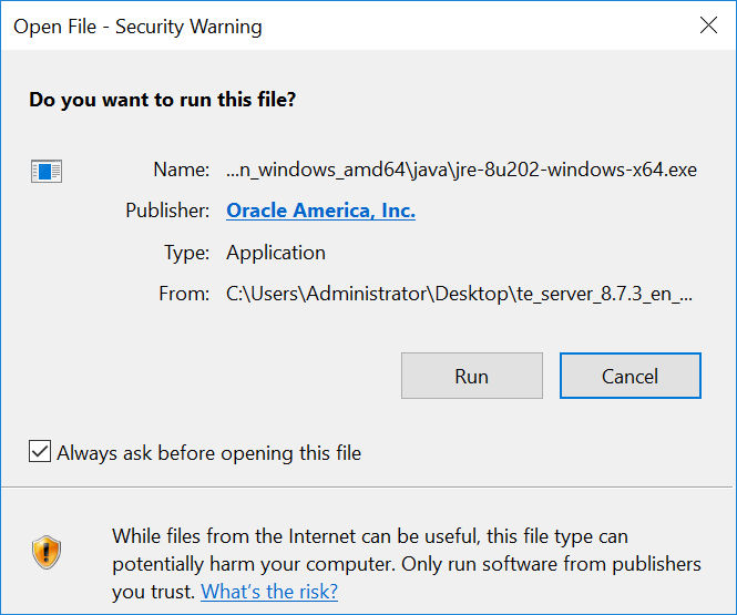
In the tripwire install folder under java, double-click the jre-8u202-windows-x64 application file.
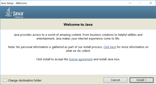
Click Run.
Click Install >.
Click OK.
Wait for the installation process to complete.
Click Close.
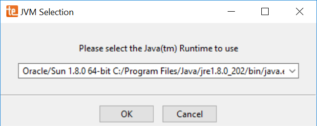
With Java installed, double-click the Tripwire install application, install-server-windows-amd64.
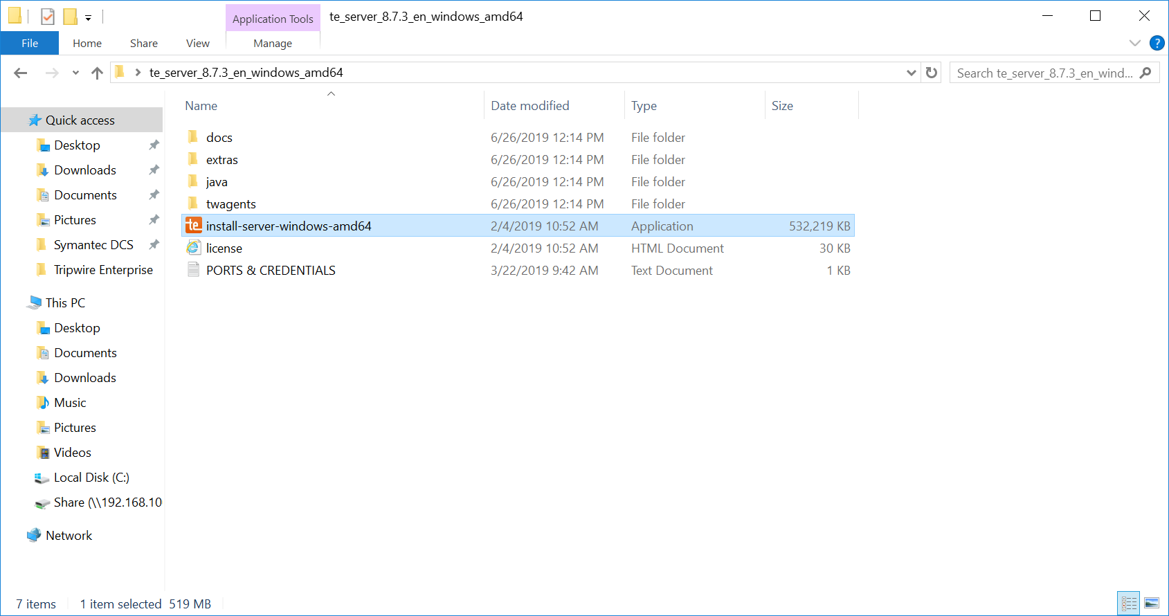
Select the version of Java, Oracle/Sun 1.8.0 64-bit, that was previously installed.
Click OK.
Click Next >.
Check I accept the agreement.
Click Next >.
Specify an installation directory, C:\Program Files\Tripwire\TE, for the Tripwire installation.
Click Next >.
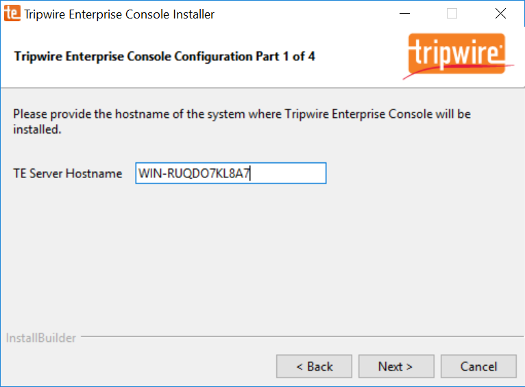
Verify the host name for the machine on which you are installing Tripwire (e.g., WIN-RUQDO7KL8A7).
Click Next >.
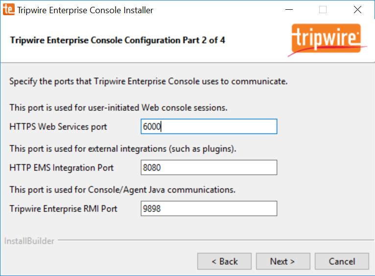
Specify the HTTPS Web Services port as 6000, HTTP EMS Integration Port as 8080, and Tripwire Enterprise RMI Port as 9898.
Click Next >.
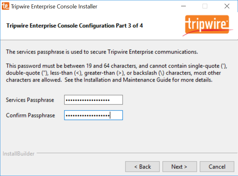
Create a password for Tripwire Enterprise services.
Click Next >.
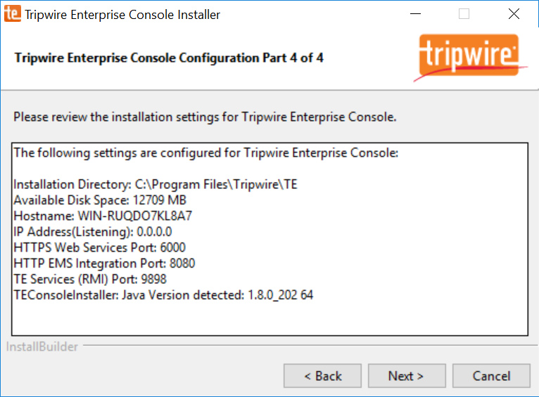
Verify that planned installation settings are correct.
Click Next >.
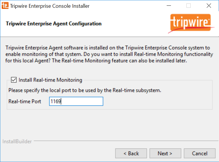
Check Install Real-time Monitoring.
Specify Real-time Port as 1169 for monitoring.
Click Next >.
Click Next >.
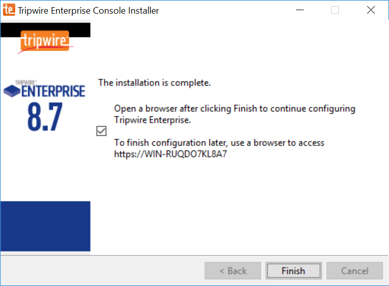
Wait for Tripwire Enterprise installation to complete.
Click Finish.
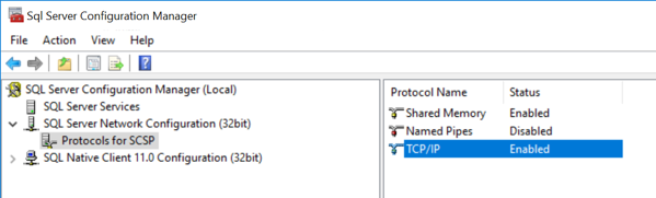
Open SQL Server Configuration Manger.
Under SQL Server Network Configuration > Protocols for SQL Server, ensure that the TCP/IP protocol is set to Enabled.
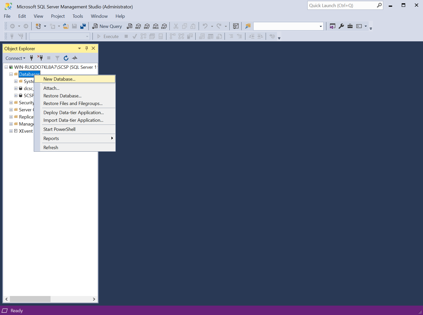
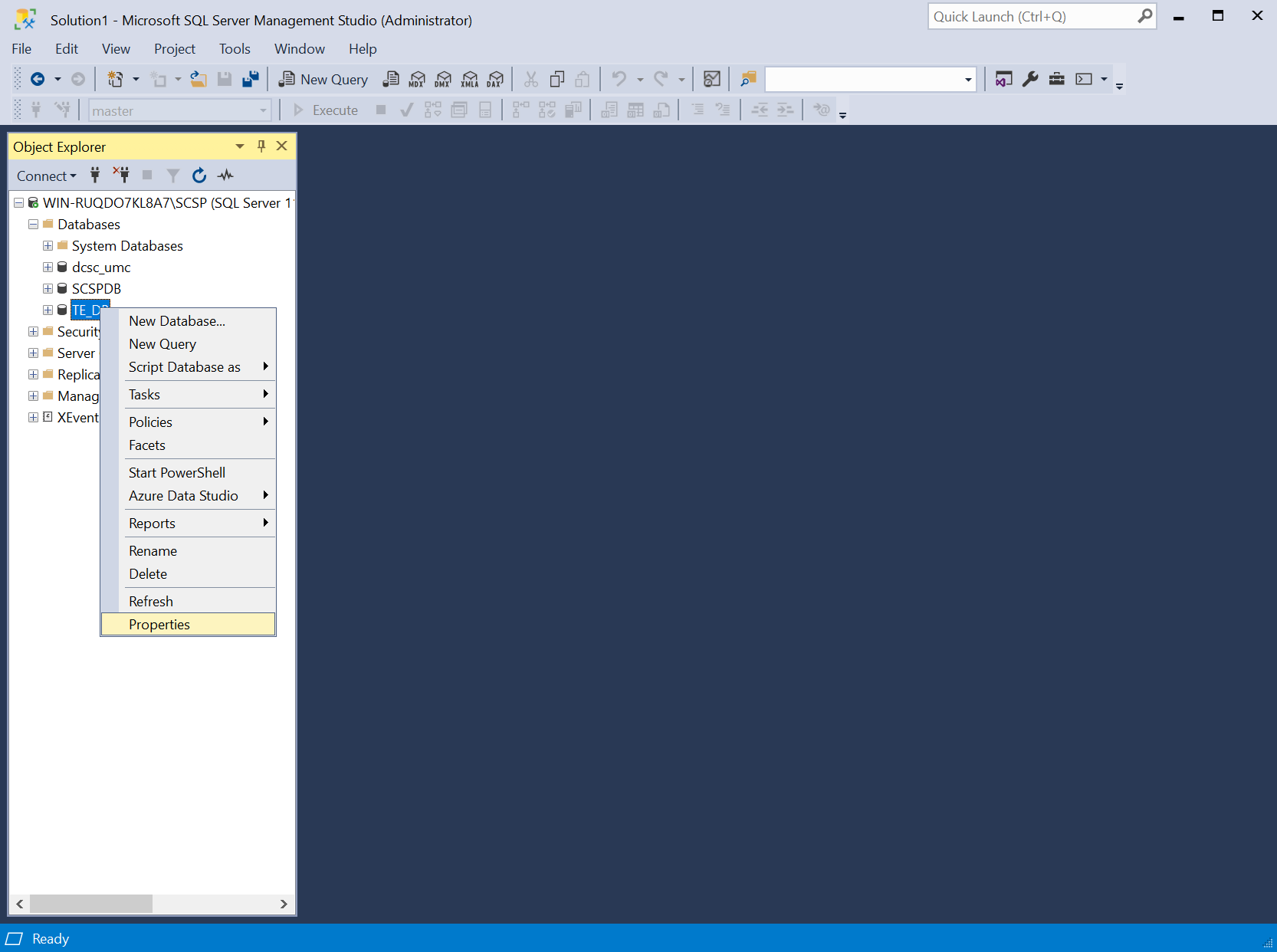
Open SQL Server Management Studio.

In the Object Explorer, expand the selection for your DB, right-click Databases, and select New Database…
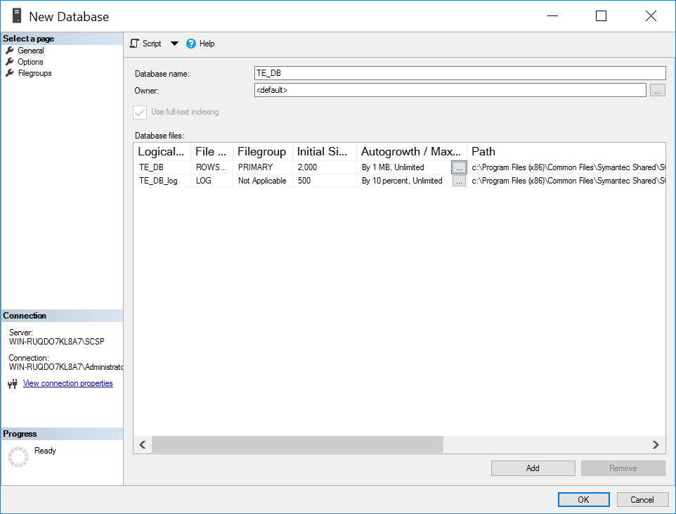
On the left, under Select a page, select General.
Enter a Database name as TE_DB.
Under Database files, for the data file, set Initial Size to at least 2,000.
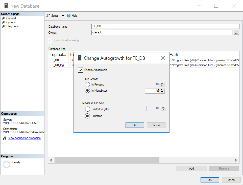
Click the button under Autogrowth.
Check Enable Autogrowth, set File Growth to at least 20 MB, and set Maximum File Size to Unlimited.
Click OK.
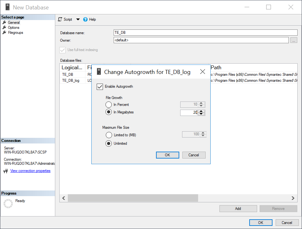
Under Database files, for the log file, set Initial Size to at least 500.
Click the in Megabytes button under Enable Autogrowth.
Check Enable Autogrowth, set File Growth to at least 20 MB, and set Maximum File Size to Unlimited.
Click OK.
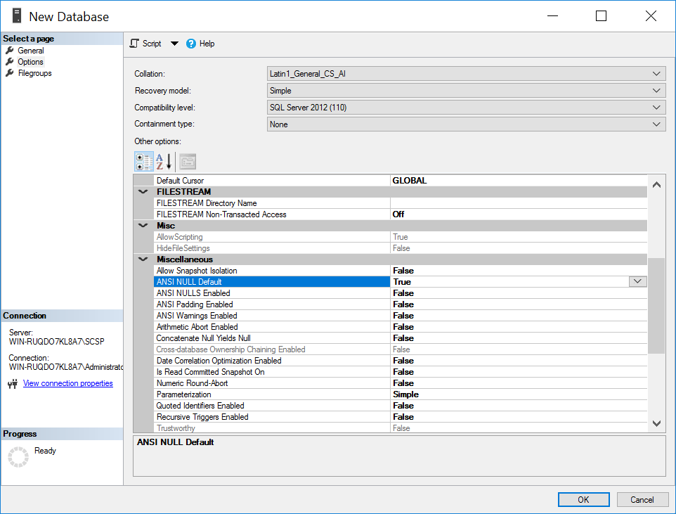
On the left, under select a page, select Options.
Set Collation to Latin1_General_CS_AI.
Set Recovery model to Simple.
Under Other Options > Miscellaneous, set ANSI NULL Default to True.
Click OK.
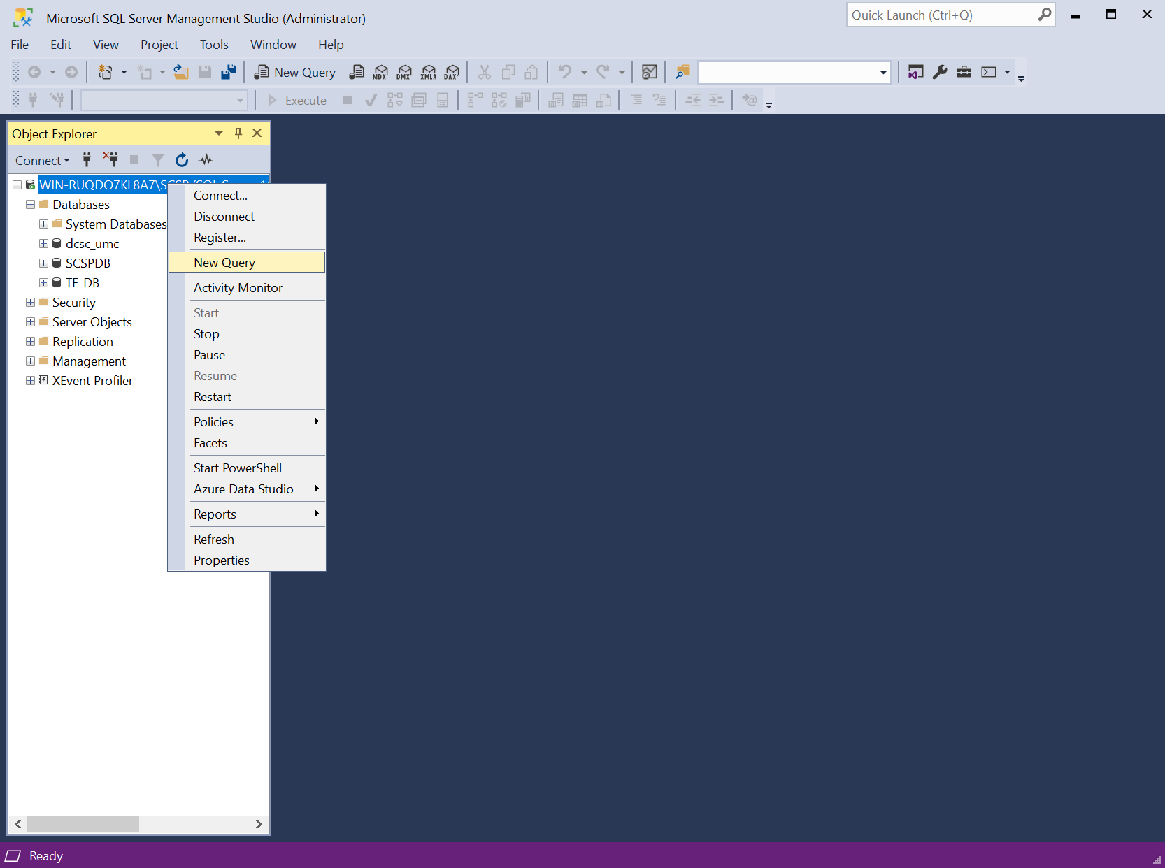
In the Object Explorer, right-click your DB and select New Query.
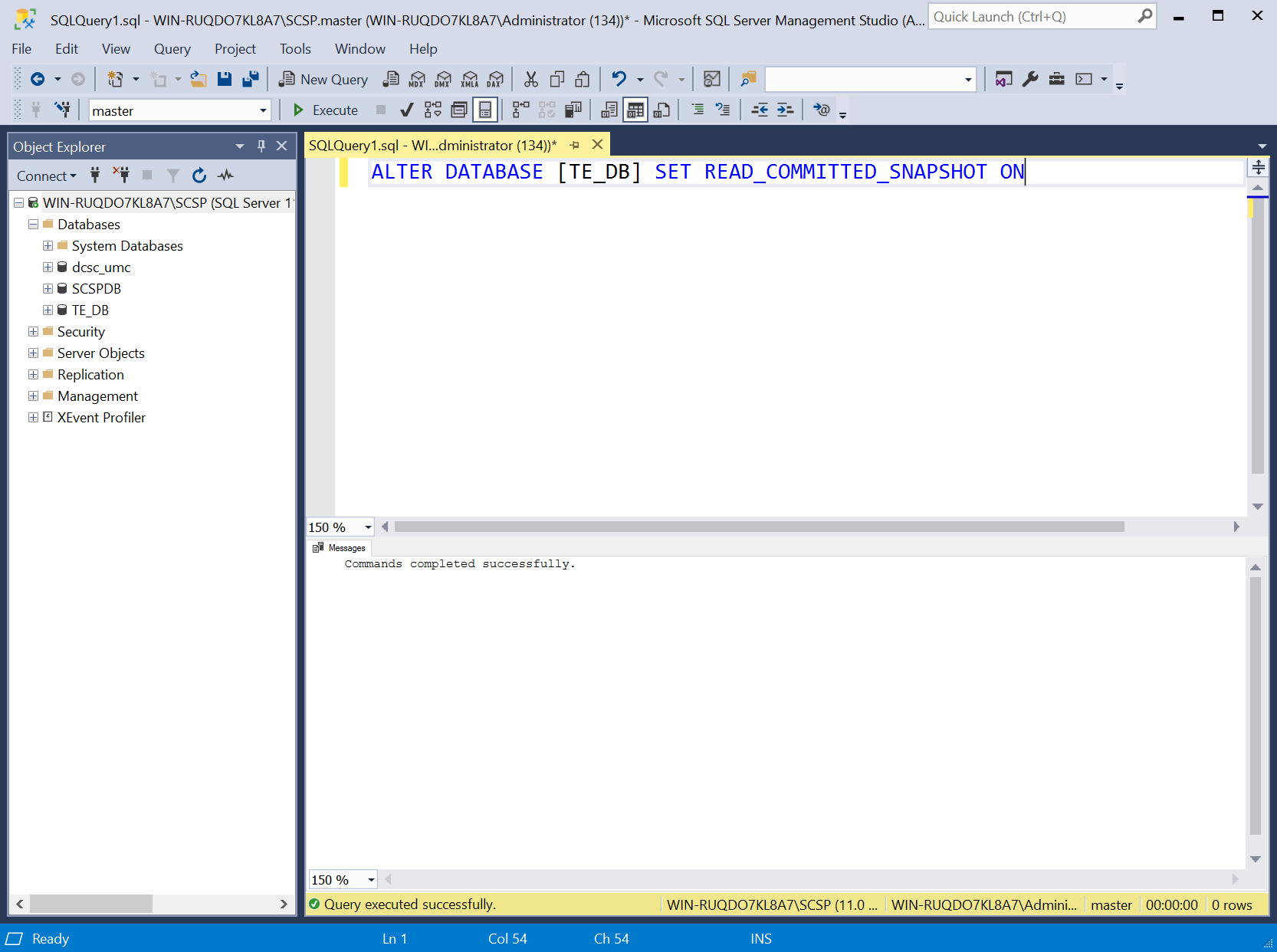
Type the following query:
ALTER DATABASE [TE_DB] SET READ_COMMITTED_SNAPSHOT ONClick Execute in the toolbar above the SQL Query window.
Under the SQL Query window, in the Messages window, verify that the command completed successfully.
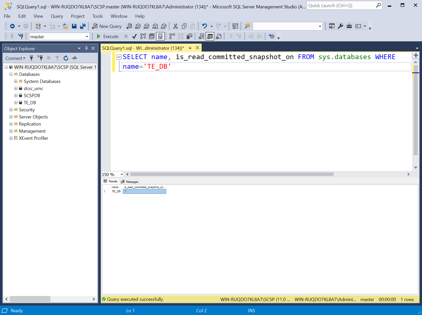
Clear the SQL Query window, then type the following query:
SELECT name, is_read_committed_snapshot_on FROM sys.databases WHERE name='<db_name>'Click Execute in the toolbar above the SQL Query window.
Under the SQL Query window, in the Messages window, verify the value for is_read_committed_snapshot_on is set to 1.
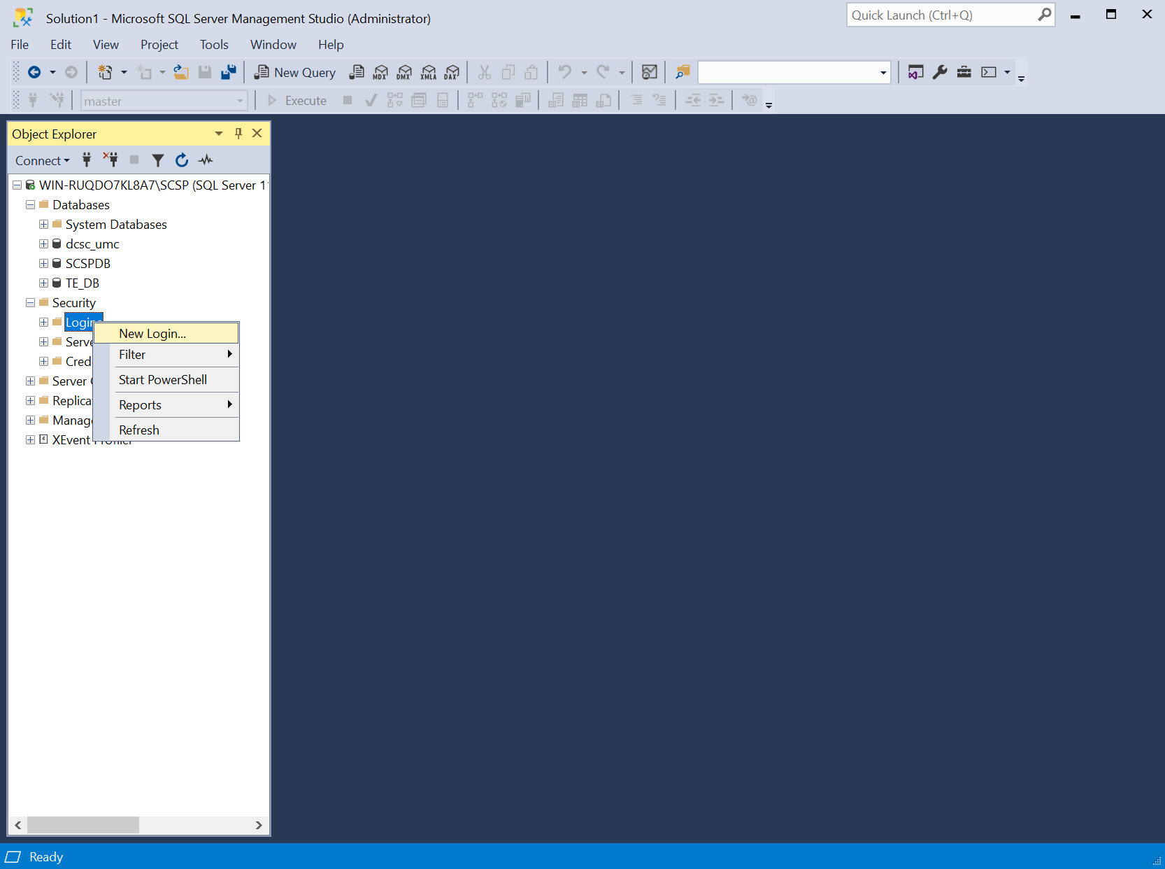
In the Object Explorer, expand the selection for your DB, expand the Security section, right-click Logins, and select New Login…
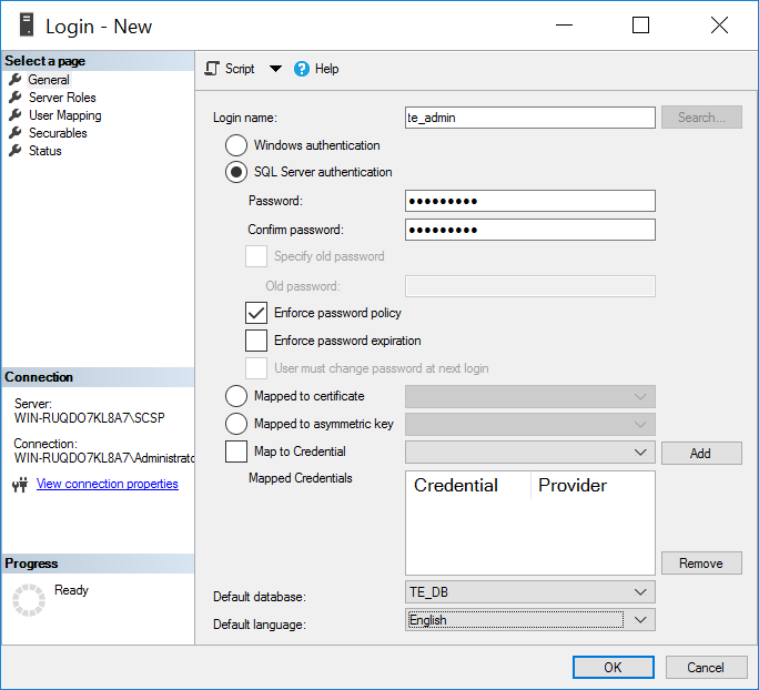
On the left, under Select a page, select General.
Create a Login name.
Select SQL Server authentication.
Create a password.
For Default database, select the DB previously created.
For Default language, select English.
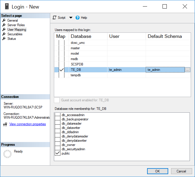
On the left, under Select a page, select User Mapping.
Under the Users mapped to this login window, perform these actions for the row containing the previously created DB:
Check the box in the Map column.
In the Default Schema column, type the name of the new user being created.
Click OK.
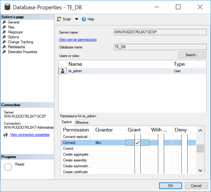
In the Object Explorer, expand the selection for your DB, expand the Databases section, right-click the DB created previously, and select Properties.
On the left, under select a page, select Permissions.
Under Permissions for user, check the box in the Grant column for the following permissions:
Connect
Create Function
Create Procedure
Create Table
Create View
Delete
Insert
Select
Update
Click OK.
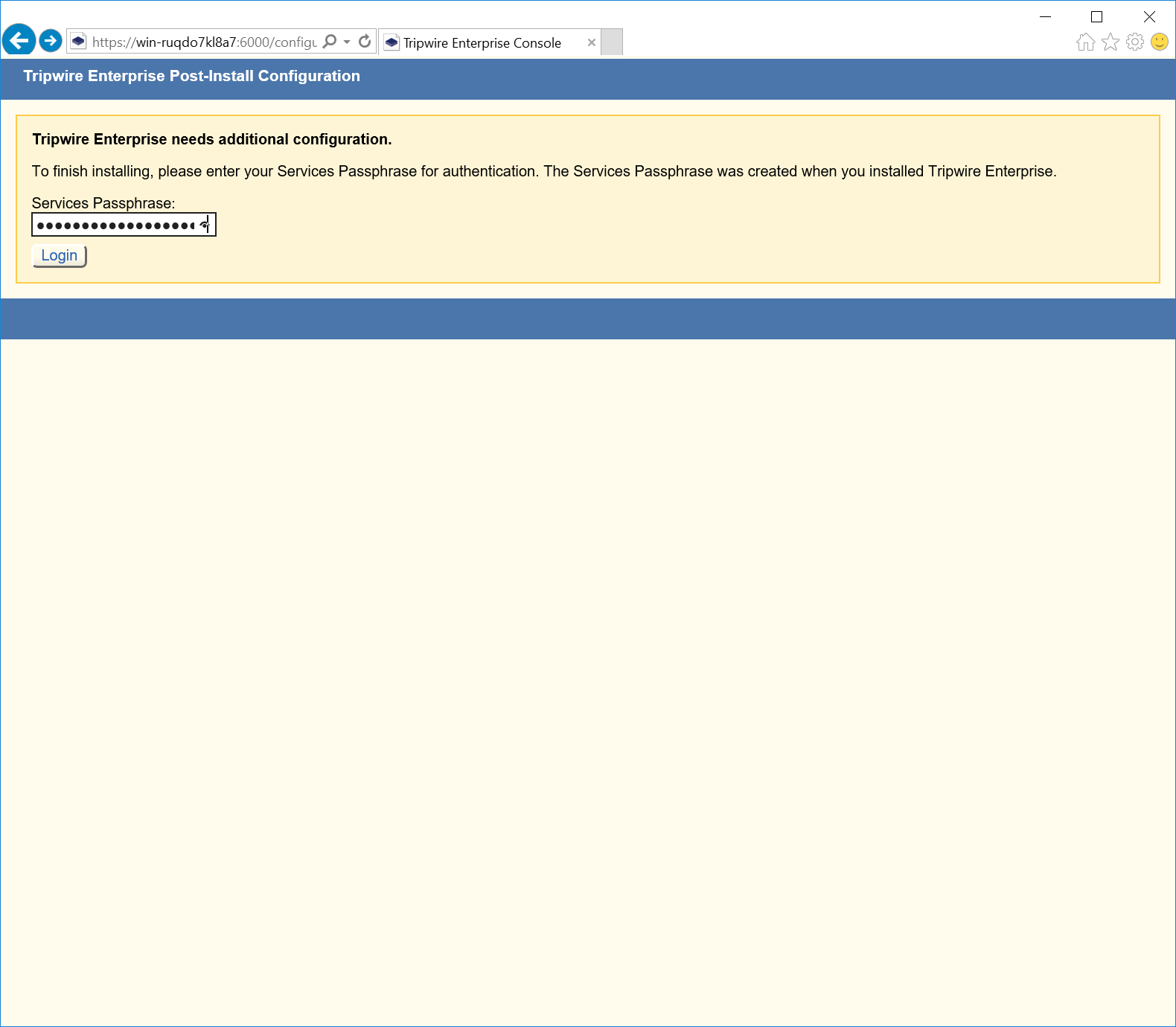
Open Internet Explorer and navigate to the web page of the server where Tripwire Enterprise was installed.
Enter the services password created during the installation process.
Click Login.
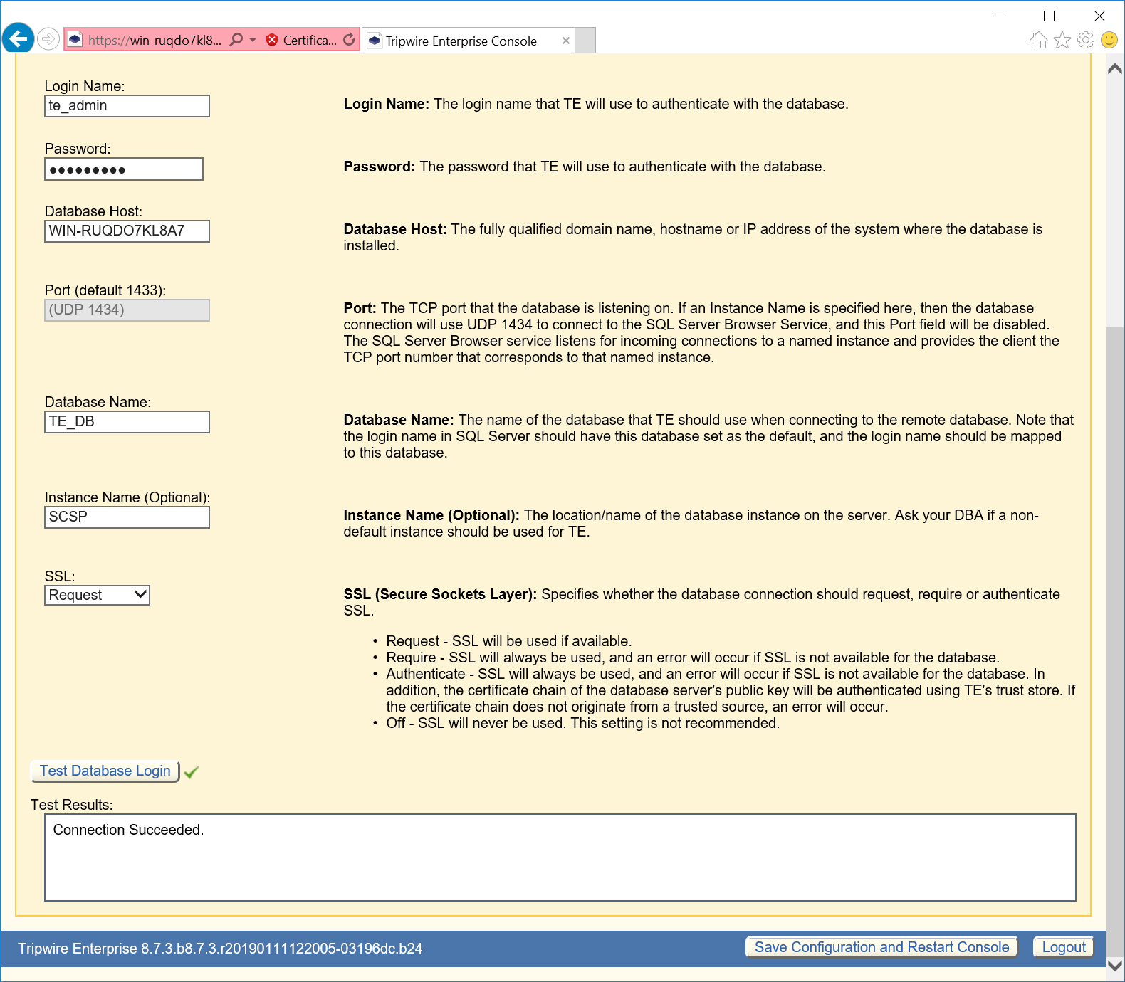
Under Database Configuration Settings, provide the information that follows:
Remote Database Type: Microsoft SQL Server
Authentication Type: SQL Server
Login Name: ********
Password: *********
Database Host: WIN-RUQDO7KL8A7
Database Name: TE_DB
Instance Name: SCSP (Note: This may not be necessary, depending on how your SQL Server Database is configured.)
SSL: Request
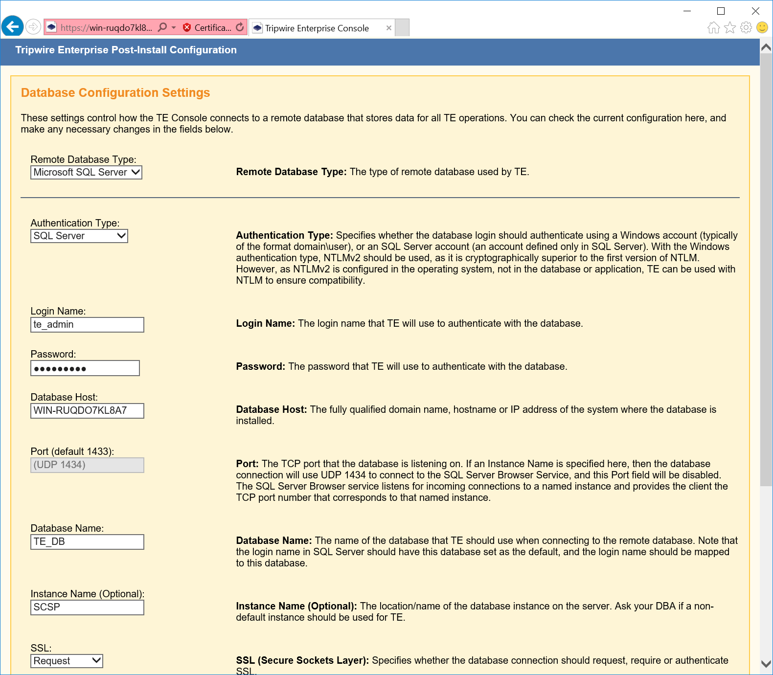
Click Test Database Login and verify that the connection is successful.
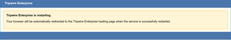
Click Save Configuration and Restart Console.
Wait for Tripwire Enterprise to restart and redirect you to the login page.
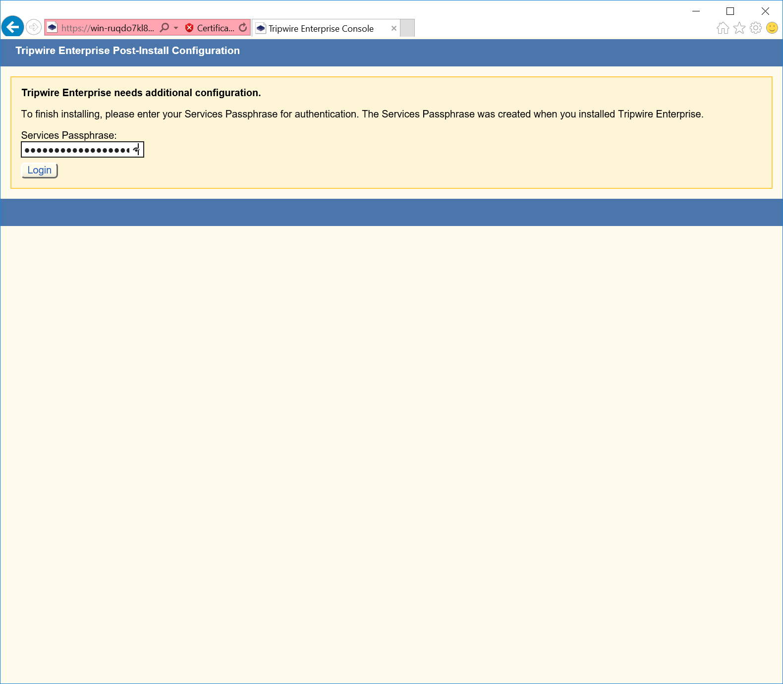
Enter the services password created during the installation process.
Click Login.
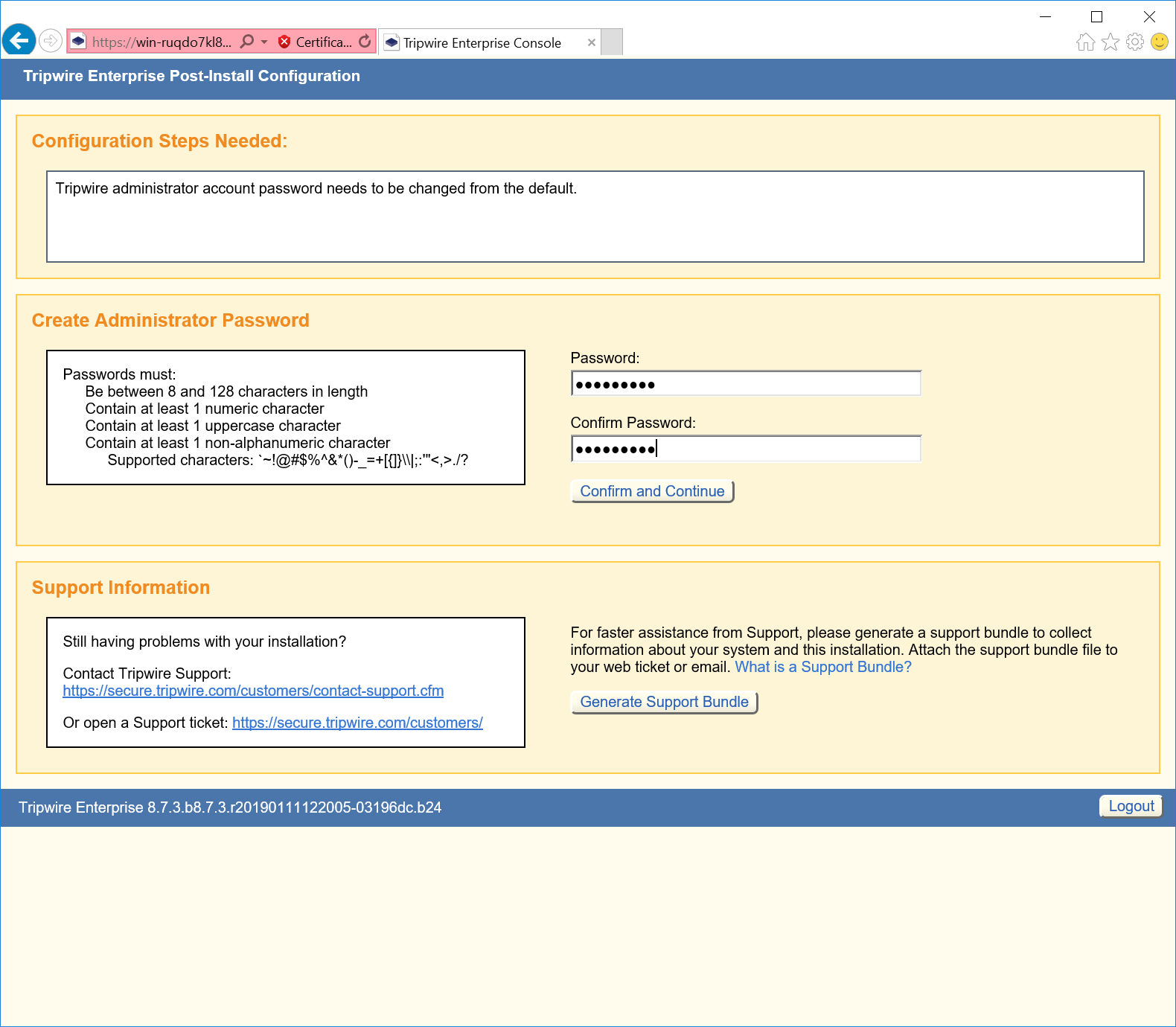
Under Create Administrator Password, create a password for the Tripwire Enterprise administrator account.
Click Confirm and Continue.
Enter the username and password for the Tripwire Enterprise administrator account.
Click Sign In.
Click Configure Tripwire Enterprise to begin the configuration process.
Tripwire Enterprise Agent Installation
Run
te_agent.msi.Click Next >.
Check I accept the terms in the license agreement.
Click Next >.
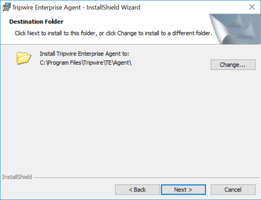
Specify an installation directory for the Tripwire Enterprise Agent.
Click Next >.
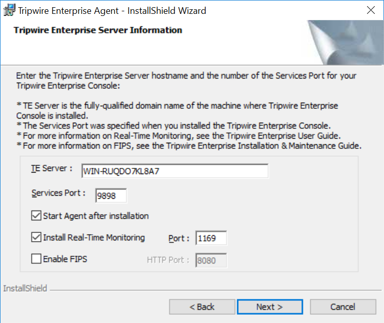
Enter the TE Server identifier (e.g., WIN-RUQDO7KL8A7) of the server where Tripwire Enterprise is installed.
Enter 9898 as the Services Port established during the installation process of Tripwire Enterprise.
After installation, check Start Agent.
Check Install Real-Time Monitoring and specify a Monitoring Port.
Uncheck Enable FIPS.
Click Next >.
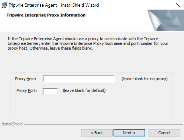
Specify a Proxy Host and Proxy Port if necessary.
Click Next >.
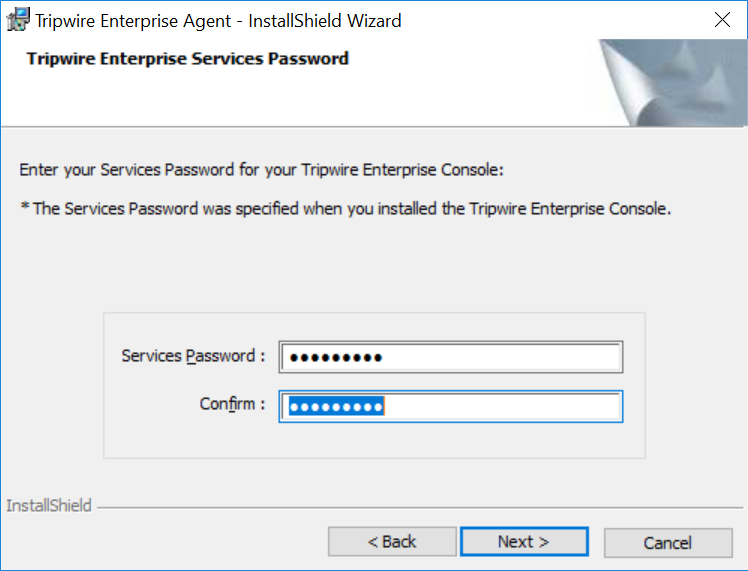
Enter the Services Password created during the installation process for Tripwire Enterprise.
Click Next >.
Click Install.
Wait for the installation process to complete.
Click Finish.
2.6 Enterprise Domain Identity Management
For this build, enterprise domain identity management relied upon Microsoft Active Directory, domain name system (DNS), and dynamic host configuration protocol (DHCP). Digital certificates were also implemented for services that enable certificate-based authentication. The build implemented these core services.
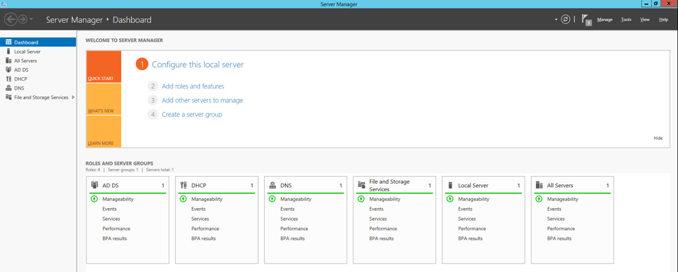
2.6.1 Domain Controller with AD, DNS, and DHCP
Within the PACS architecture, we established a Windows Server 2012 R2 Domain Controller to manage AD, DNS, and DHCP services for the enterprise. The following section details how the services were installed.
System Requirements
CPU: 1
Memory: 4 GB RAM
Storage: 120 GB (thin provision)
Operating System: Microsoft Windows Server 2012 R2
Network Adapter: VLAN 1201
Enterprise Domain Services Installation
Install the DC, AD, and DNS appliances according to the instructions detailed in Building Your First Domain Controller on 2012 R2 [C5].
DNS Server Forward Lookup Zone Configuration
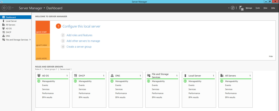
Open Server Manager.
In the top right, click Tools > DNS.
The DNS forward lookup zone should have already been created during the DNS setup process performed previously. If not, follow these instructions:
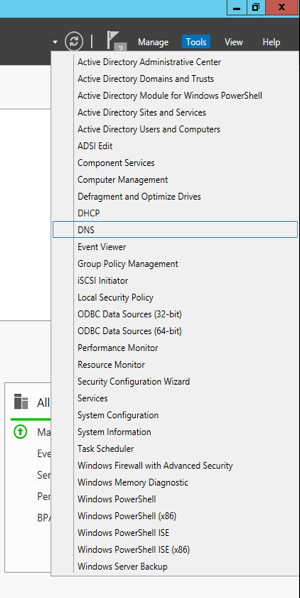
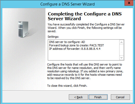
Right-click your server’s name, and select Configure a DNS Server…
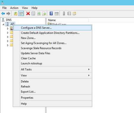
Click Next >.
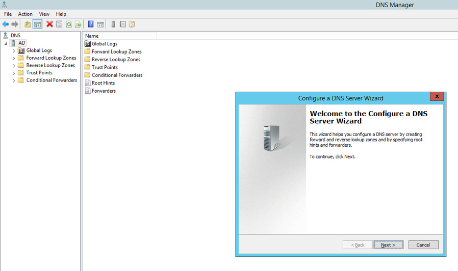
Click Next >.
Under Select Configuration Action, select Create a forward loading zone…
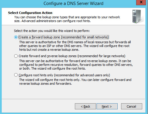
Click Next >.
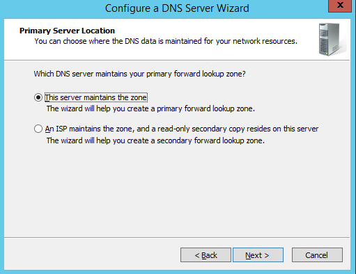
Under Primary Server Location, select This server maintains the zone
Click Next >.
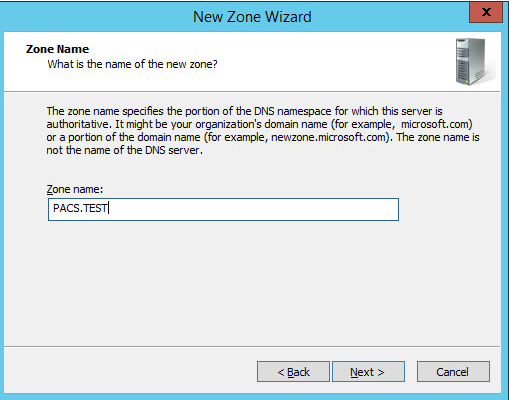
Enter PACS.TEST as the Zone name that was established previously during setup.
Click Next >.
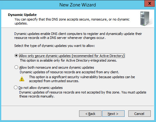
Select Allow only secure dynamic updates.
Click Next >.
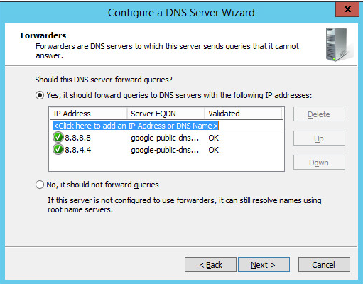
Add Forwarders (8.8.8.8 and 8.8.4.4 are Google’s DNS servers).
Click Next >.
Click Finish.
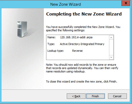
DNS Server Reverse Lookup Zone Configuration
Open Server Manager.
In the top right, click Tools > DNS.

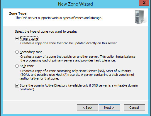
Right-click Reverse Lookup Zones folder, and select New Zone…
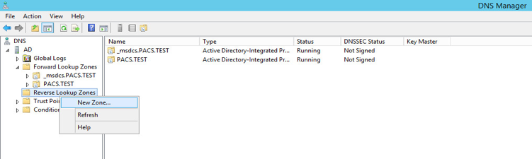
Click Next >.
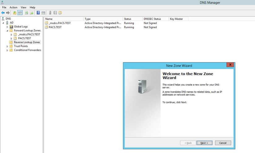
Click Next >.
Under Zone Type, select Primary zone.
Select the Store the zone in Active Directory… checkbox.
Click Next >.
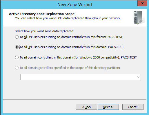
Click Next >.
Under Active Directory Zone Replication Scope, Select To all DNS servers running…
Click Next>.
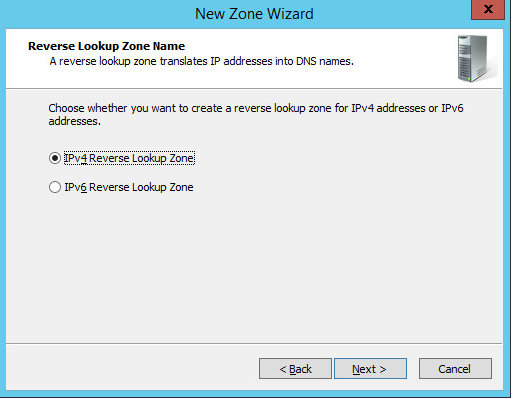
Choose the Internet Protocol version 4 (IPv4)—IPv4 Reverse Lookup Zone option—and click Next >.
Establish what IP addresses should be included in reverse lookup (the example above encompasses all devices in the 192.168.120.0/24 subnet), then click Next >.
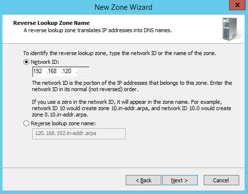
Choose the Allow only secure dynamic updates (recommended for Active Directory) option, then click Next >.
Click Finish.
DHCP Server Installation
Install the DHCP server according to the instructions detailed in Installing and Configuring DHCP Role on Windows Server 2012 [C6].
DHCP Server Configuration
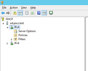
Open Server Manager.

In the top right, click Tools > DHCP.
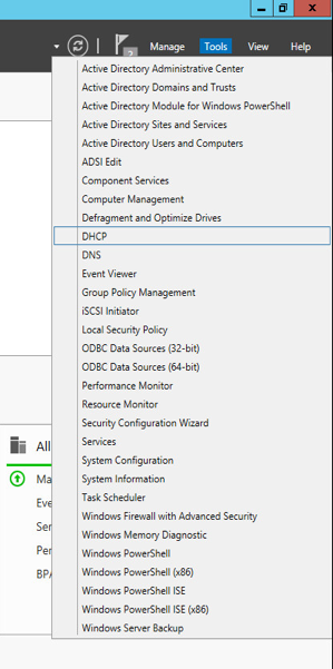
If you see a green check mark on the IPv4 server, the DHCP server is up and running.
DHCP Scopes Configuration
Performed on Windows Server 2012 R2
Open Server Manager.

In the top right, click Tools > DHCP.
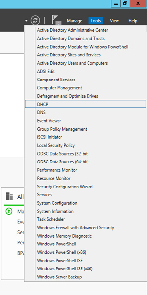
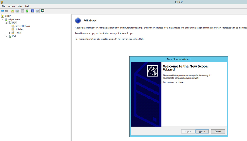
Right-click IPv4, and select New Scope…
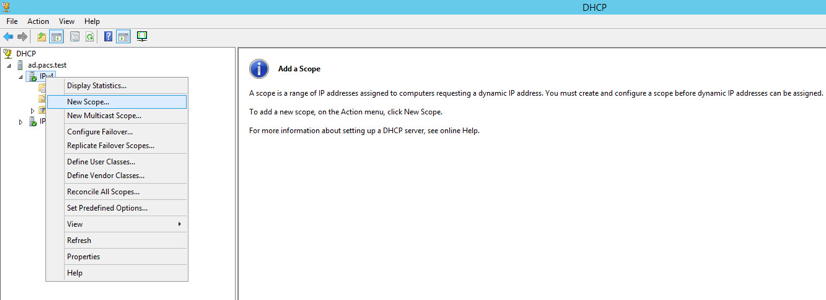
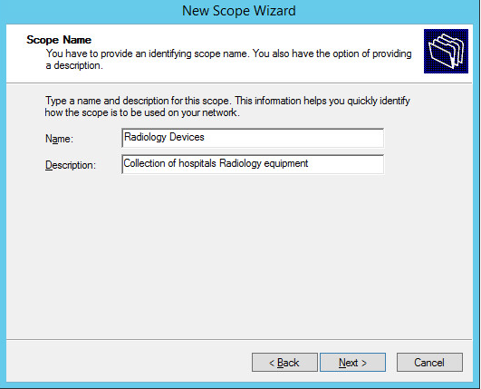
Click Next >.
Provide a Name such as Radiology Devices and a Description such as Collection of hospitals Radiology equipment in the New Scope Wizard.
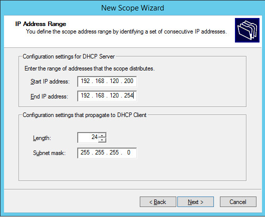
Click Next >.
Establish the IP range (192.168.120.200–192.168.120.254) from which the DHCP server should hand out IPs for devices in this scope.
Click Next >.
Click Next >.
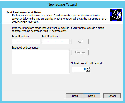
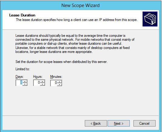
Configure preferred Lease Duration (e.g., 8 days), and click Next >.
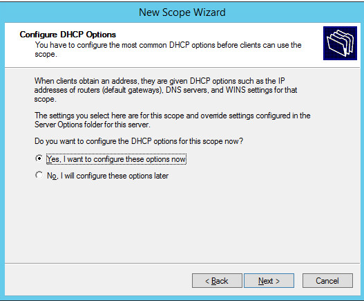
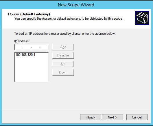
Choose Yes, I want to configure these options now, then click Next >.
Enter the subnet’s Default Gateway as 192.168.120.1.
Click Add.
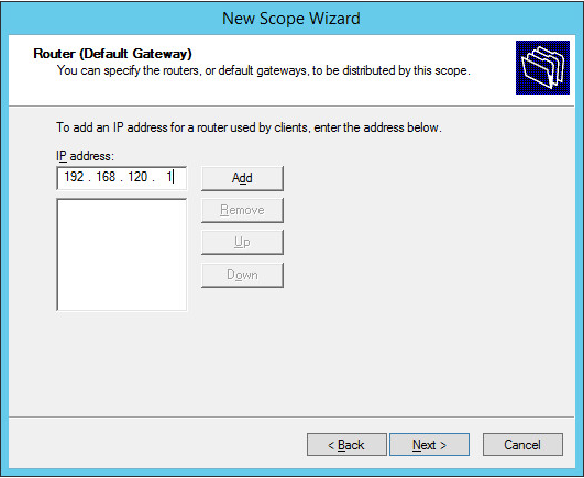
Click Next >.
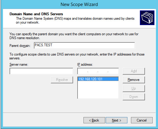
Ensure IP address in bottom-right box is the IP address (192.168.120.101) for the DNS server configured earlier.
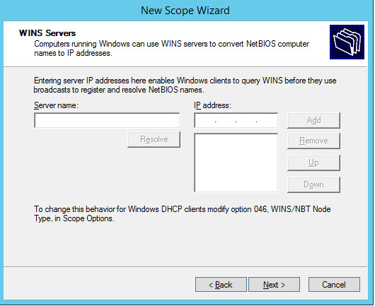
Click Next >.
Click Next >.
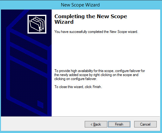
Choose Yes, I want to activate this scope now option, then click Next >.
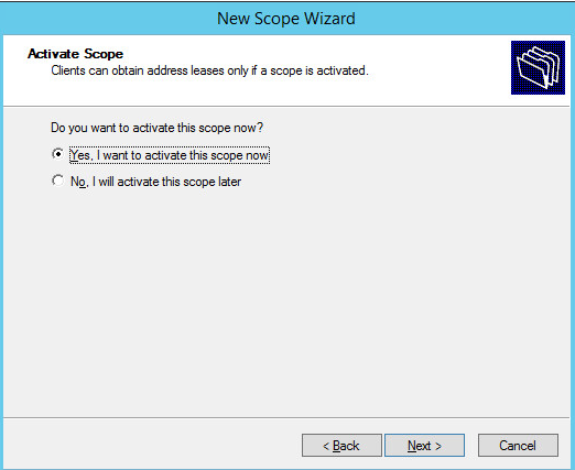
Click Finish.
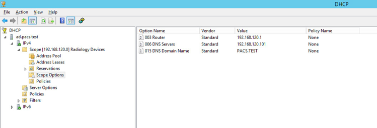
Scope should appear under the IPv4 drop-down. Ensure Scope Options are correctly established with these values:
003 Router: 192.168.120.1
006 DNS Servers: 192.168.120.101
015 DNS Domain Name: PACS.TEST
2.6.2 DigiCert PKI
DigiCert is a cloud-based platform designed to provide a full line of SSL certificates, tools, and platforms for optimal certificate life-cycle management. To use the service, an account must be established with DigiCert. Once an account is established, access to a DigiCert dashboard is enabled. From the dashboard, DigiCert provides a set of certificate management tools to issue PKI certificates for network authentication and encryption for data-at-rest or data-in-transit as needed.
The instructions below describe the process to obtain an SSL certificate on behalf of medical devices using the DigiCert certificate signing services.
Create CSR
A CSR is represented as a block Base64 encoded Public Key Cryptography Standards (PKCS)#10 binary format text that will be sent to a CA for digital signature when applying for an SSL certificate. The CSR identifies the applicant’s distinguished common name (domain name), organization name, locality, country, and the public key. The CSR is usually generated from the device where the certificate will be installed, but it can also be generated using tools and utilities on behalf of the device to generate a CSR. Below are instructions on how to use the Certificate Utility for Windows (DigiCertUtil.exe) provided by DigiCert to generate CSRs for a medical device or a server.
Download and save the DigiCertUtil.exe from the DigiCert site [C7].
Double-click DigiCertUtil.exe to run the utility.
Click the Create CSR link to open a CSR request window.
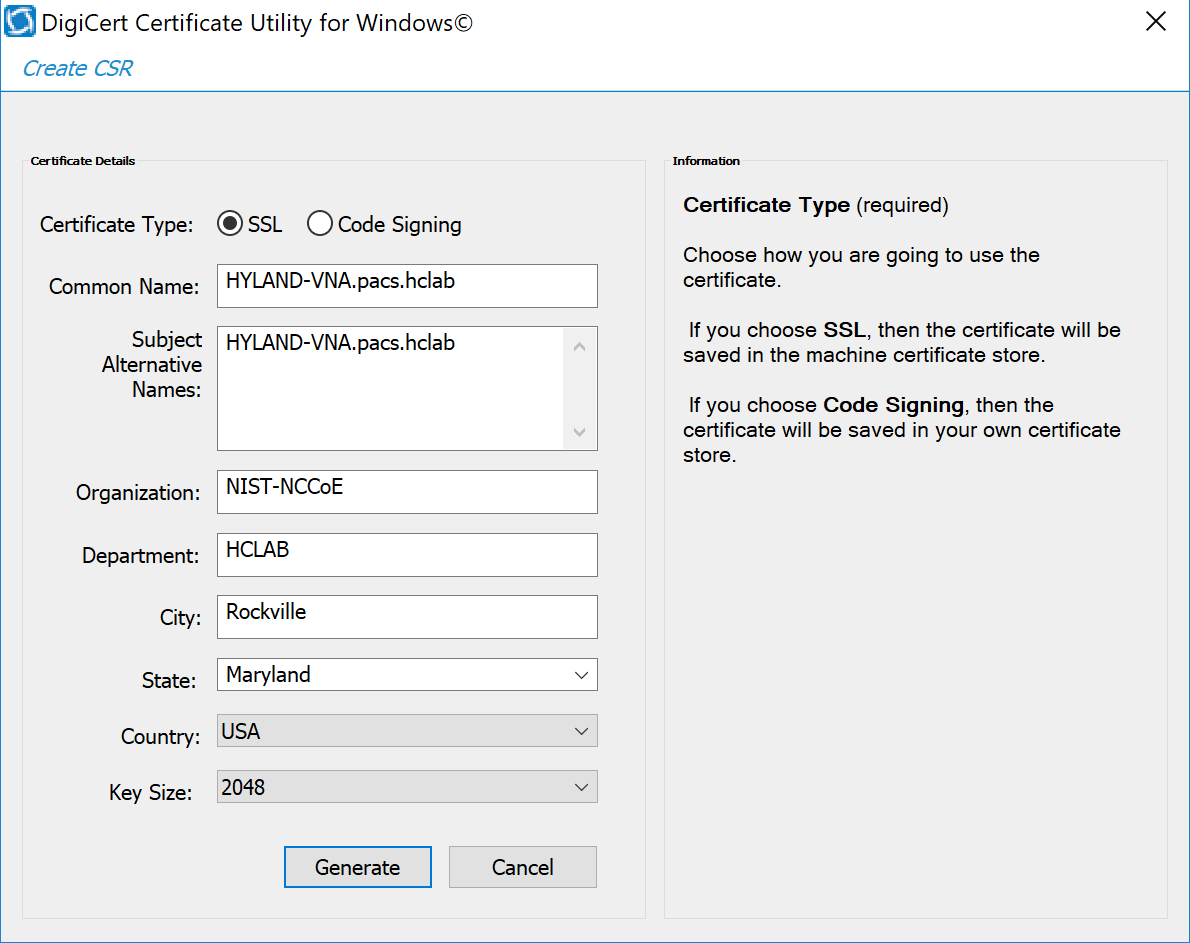
On the Create CSR window, fill in the key information (some of the information is optional).
Certificate Type: Select SSL
Common Name: HYLAND-VNA.pacs.hclab
Subject Alternative Names: HYLAND-VNA.pacs.hclab
Organization: ********
Department: HCLAB
City: Rockville
State: Maryland
Country: USA
Key Size: 2048
Click Generate to create a CSR. This will also generate a corresponding private key in the Windows computer from which the CSR is requested. The Certificate Enrollment Request is stored under Console Root\Certificates(Local Computer)\Certificate Enrollment Requests\Certificates.
The figure below is a sample CSR.
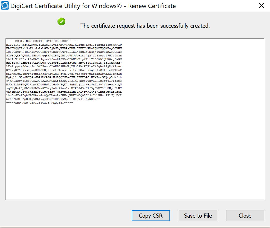
Select and copy the certificate contents to the clipboard or save to an American Standard Code for Information Interchange text file. Use the text contents to paste into the DigiCert order form.
Issue Signed Certificates. With a created applicant CSR, request a signed certificate using DigiCert CertCentral portal by following these steps:
Log in to a DigiCert dashboard (https://www.digicert.com/account/login.php) with your account username and password. In the portal, select CERTIFICATES > Requests, then navigate to Request a Certificate, and select Private SSL to open a certificate request form.
Paste the CSR information to the area called Add Your CSR, including the —–BEGIN NEW CERTIFICATE REQUEST—– and —–END NEW CERTIFICATE REQUEST—– tags. Once the pasting is done, some of the fields will be populated automatically.
After filling in all the required information, scroll down to the bottom of the page, and select the I Agree to the Certificate Services Agreement Above checkbox. Next, click the Submit Certificate Request button at the bottom of the form to submit the certificate for signing approval.
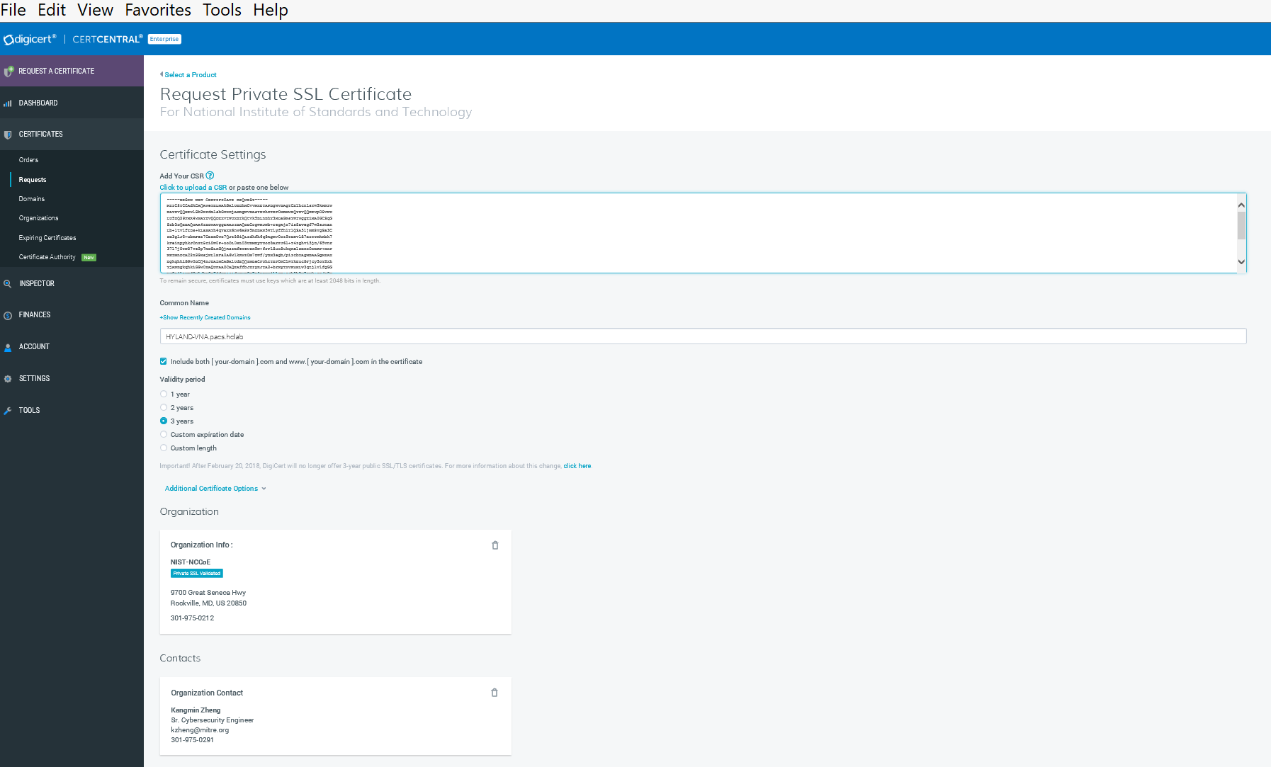
The certificate is listed under Orders. Once the order status changes to Issued, the certificate is ready for download.
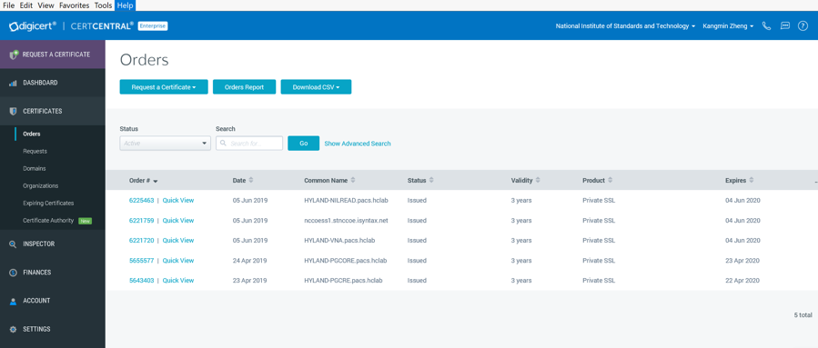
Click a specific order number to display the certificate details with a list of actions that can be performed. Click Download Certificate As to download certificates with signed CA and Root CA certificates. A variety of certificate formats can be downloaded, such as .crt, .p7b, .pem.
Save the downloaded certificate in a location where it can be used for further processing if needed.
Import and Export the Signed Certification
After downloading the SSL certificate from DigiCert, you can use the DigiCert Certificate Utility for Windows to install it. With the DigiCert Utility tool, you can further manipulate the certificates to combine with the private key and export the signed certificate to the certificate requesting device server.
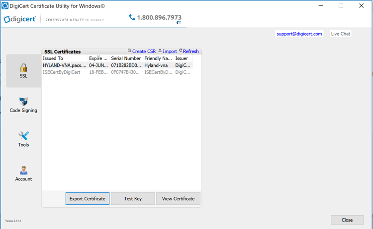
From the DigiCert Certificate Utility for Windows, click the Import button to load the downloaded signed Certificate file to the utility. The downloaded file was saved in step 10 of Section 2.6.2. Click the Next button to import.
From the DigiCert Certificate Utility for Windows, click SSL to list all the imported files.
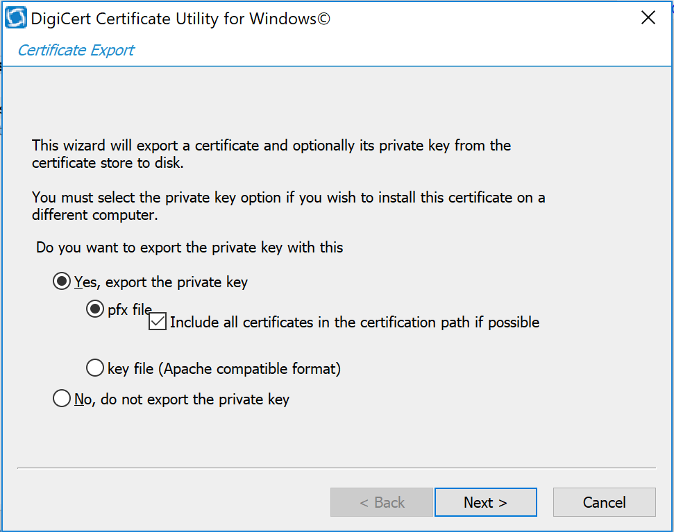
To export the certificate, select the certificate you want to export as a combined certificate file and key file in a .pfx file or separated as a certificate file and key file, then click Export Certificate.
Click the Next > button, then follow the wizard instructions to save the certificate file and private key file to a desired location in the device.
2.7 Network Control and Security
Network control and security was implemented throughout the network infrastructure. The build features perimeter security that includes firewall feature sets and network traffic monitoring. The internal lab environment implements VLANs to establish network zones. Modality devices are further isolated by using micro-segmentation. The build also includes behavioral analysis tools that alert upon anomalous activity.
2.7.1 Cisco Firepower
Cisco Firepower, consisting of Cisco Firepower Management Center and Cisco Firepower Threat Defense, is a network management solution that provides firewall, intrusion prevention, and other networking services. For this project, Firepower was used to provide network segmentation and both internal and external routing. Access control and intrusion prevention policies were also implemented.
Cisco Firepower Management Center Appliance Information
CPUs: 8
RAM: 16 GB
Storage: 250 GB (thin provision)
Network Adapter 1: VLAN 1201
Operating System: Cisco Fire Linux
Cisco Firepower Management Center Virtual Installation Guide
Install the Cisco Firepower Management Center Virtual appliance according to the instructions detailed in Cisco Firepower Management Center Virtual for VMware Deployment Quick Start Guide [C8].
Cisco Firepower Threat Defense Appliance Information
CPUs: 8
RAM: 16 GB
Storage: 48.5 GB (thin provision)
Network Adapter 1: VLAN 1201
Network Adapter 2: VLAN 1201
Network Adapter 3: VLAN 1099
Network Adapter 4: VLAN 1099
Network Adapter 5: Trunk Port
Network Adapter 6: Trunk Port
Network Adapter 7: VLAN 1101
Network Adapter 8: VLAN 1101
Network Adapter 9: VLAN 1701
Operating System: Cisco Fire Linux
Cisco Firepower Threat Defense Virtual Installation Guide
Install the Cisco Firepower Threat Defense Virtual appliance, according to the instructions detailed at Cisco Firepower Threat Defense Virtual for VMware Getting Started Guide [C9].
Adding Firepower Threat Defense (FTD) Appliance to Firepower Management Center (FMC)
Log in to the FMC Console.
Navigate to Devices > Device Management.
Click the Add drop-down button and select Add Device.
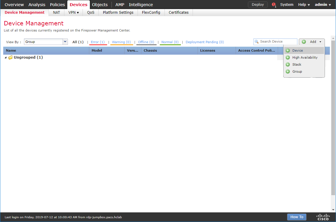
Enter 192.168.120.141 as the IP address of the FTD appliance.
Enter FTD-PACS as a display name to identify the FTD appliance.
Enter the manager key created when configuring the manager on the FTD appliance.
Click the Access Control Policy drop-down and select Create New Policy.
Create a name for the policy.
Select Block All Traffic.
Click Save.
Under Smart Licensing, check the boxes next to Malware, Threat, and URL.
Under Advanced, check the box next to Transfer Packets.
Click Register.
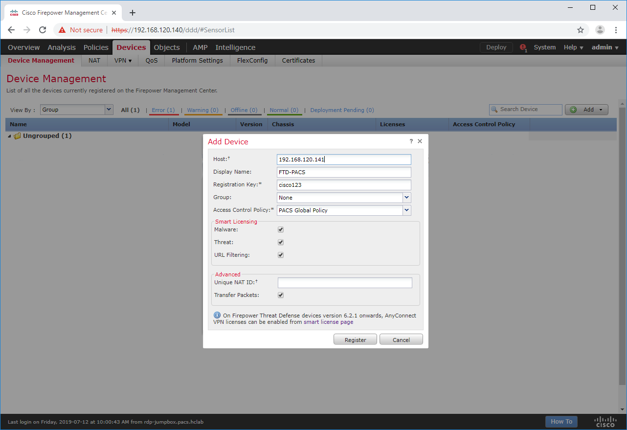
The FTD appliance will be added to the FMC’s device list.
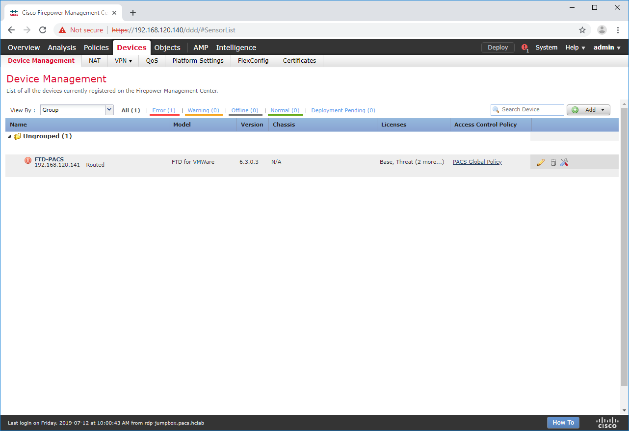
FTD Interfaces for PACS Architecture Configuration
Each physical interface connected to the Cisco FTD will appear in the FMC device management section under the interface tab. To configure the eight subnets needed for the PACS architecture while also allowing management, diagnostic, and wide area network (WAN) traffic, we dedicated two interfaces set up as a redundant pair for all internal subnet traffic. To accomplish this, a sub-interface was created for each of the eight PACS subnets (e.g., Enterprise Services, Imaging Modalities, Security Services) and established redundant interfaces for WAN traffic and traffic on VLAN 1101. The following guidance describes how the redundant interfaces and sub-interfaces were created.
Log in to the FMC Console.
Navigate to Devices > Device Management.
Find your FTD device and click the edit icon.
Navigate to Add Interfaces > Redundant Interface.
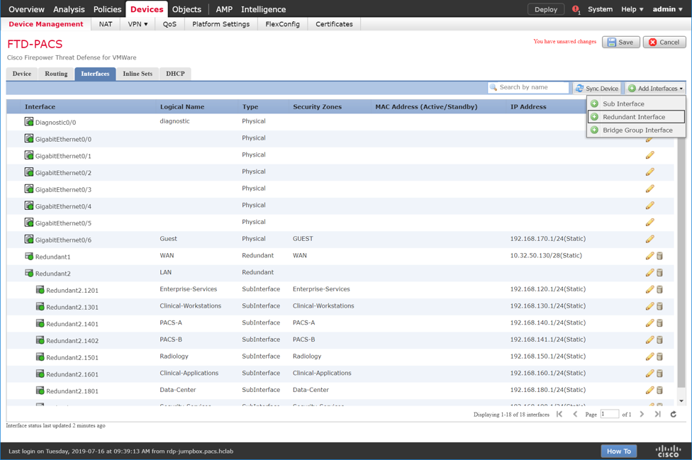
Enter Internal-Network as the name for the redundant interface.
Create and/or add a security zone to the redundant interface.
Assign a Redundant ID (e.g., Internal-Network) to the redundant interface.
Select a primary interface and secondary interface for the redundant pair.
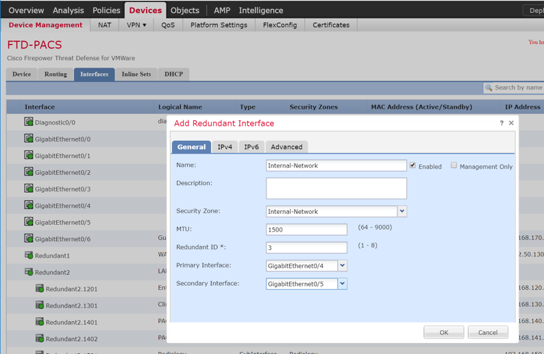
Navigate to the IPv4 tab.
Assign an IP address and netmask (e.g., 192.168.100.101/24) to the interface.
Click OK.
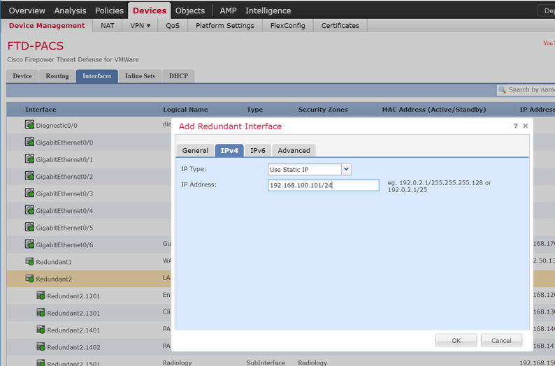
Navigate to Add Interfaces > Sub Interface.
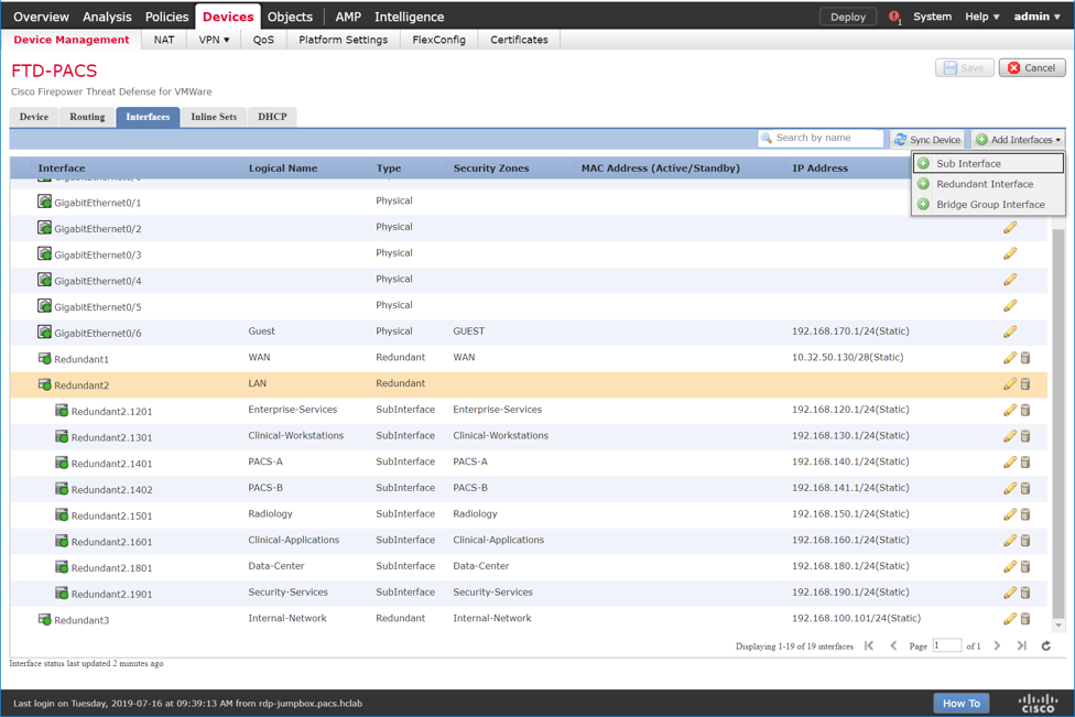
Enter VNA as the name for the subinterface.
Create and/or add a security zone, VNA, to the subinterface.
Select an interface under which the subinterface will operate.
Note: For our build, we placed each subinterface under Redundant 2, the redundant interface for GigabitEthernet0/2 and GigabitEthernet0/3. These two physical interfaces were the destination for each VLAN’s traffic.
Assign 1403 as the Sub Interface ID to the subinterface.
Assign 1403 as the VLAN ID to the subinterface.
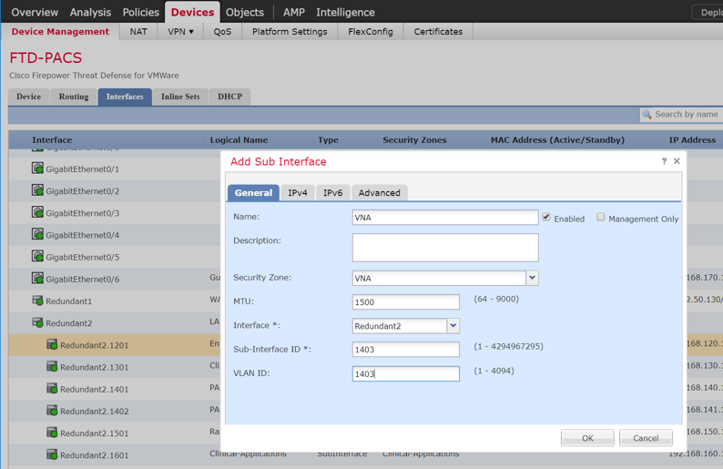
Navigate to the IPv4 tab.
Assign an IP address and netmask (e.g., 192.168.142.1/24) to the subinterface.
Click OK.
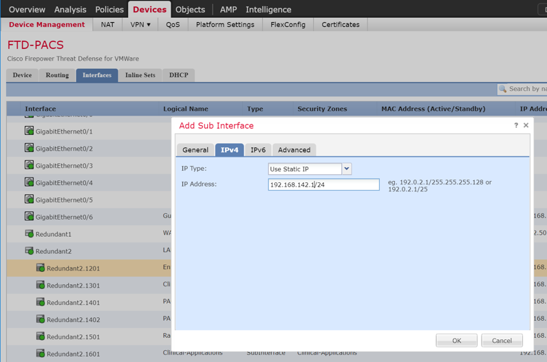
Click Save.
Click Deploy and wait for deployment to FTD to complete.
Refresh the page and confirm that the redundant interface and subinterface are running (shown with a green dot on the interface’s icon).
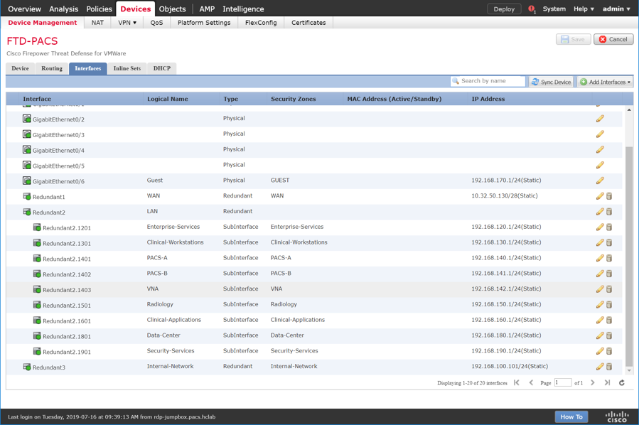
DHCP Relay Through Cisco Firepower Management Center Configuration
Log in to the FMC Console.
Navigate to Devices > Device Management.
Find your FTD device and click the edit icon.
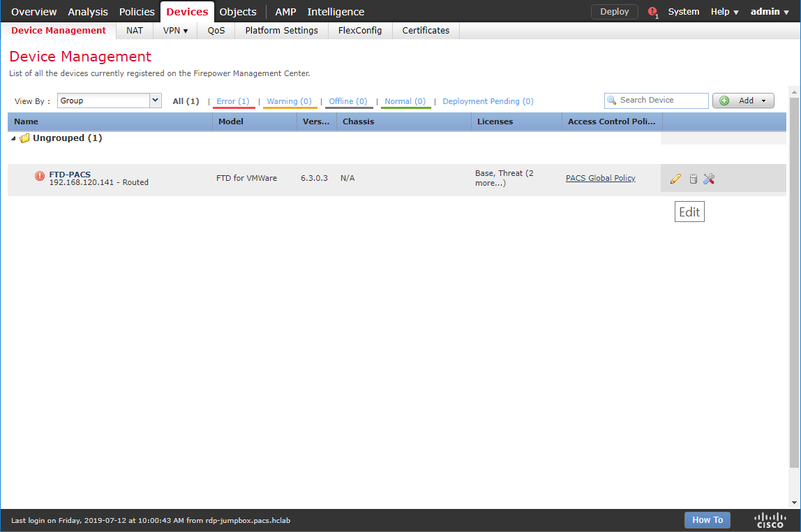
Navigate to the DHCP tab.
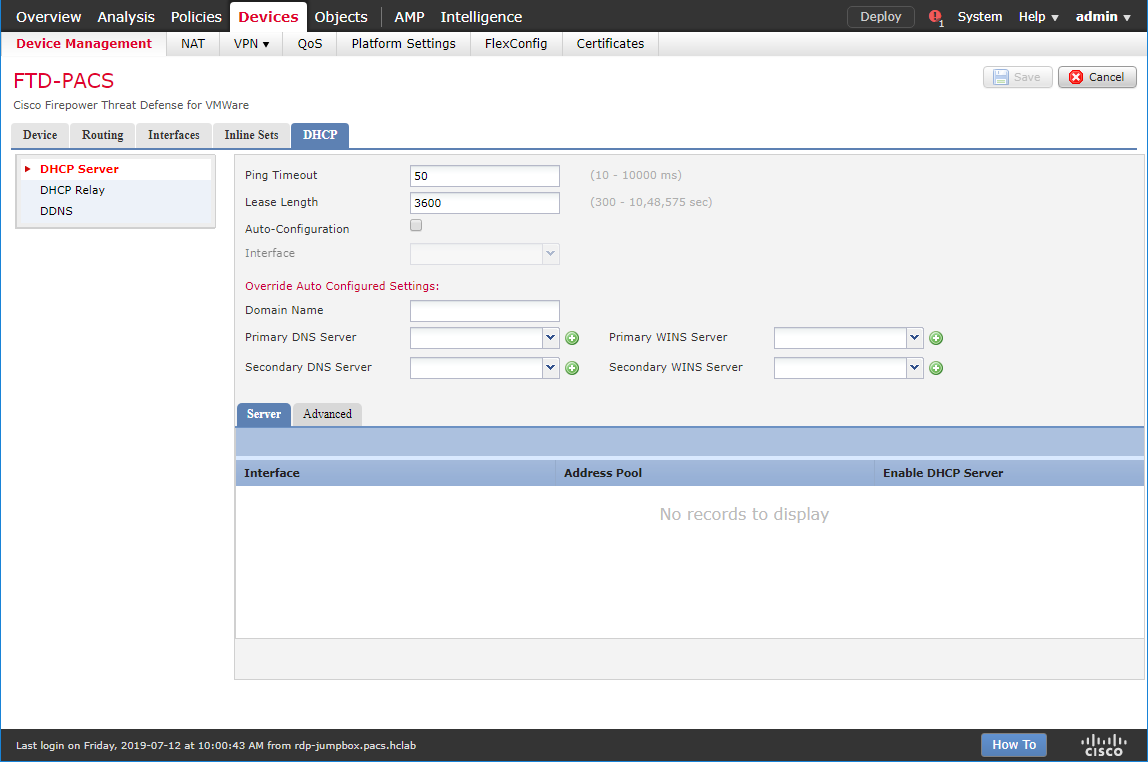
Navigate to the DHCP Relay Agent section.
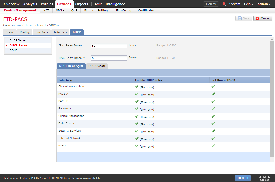
Under DHCP Relay Agent, click Add.
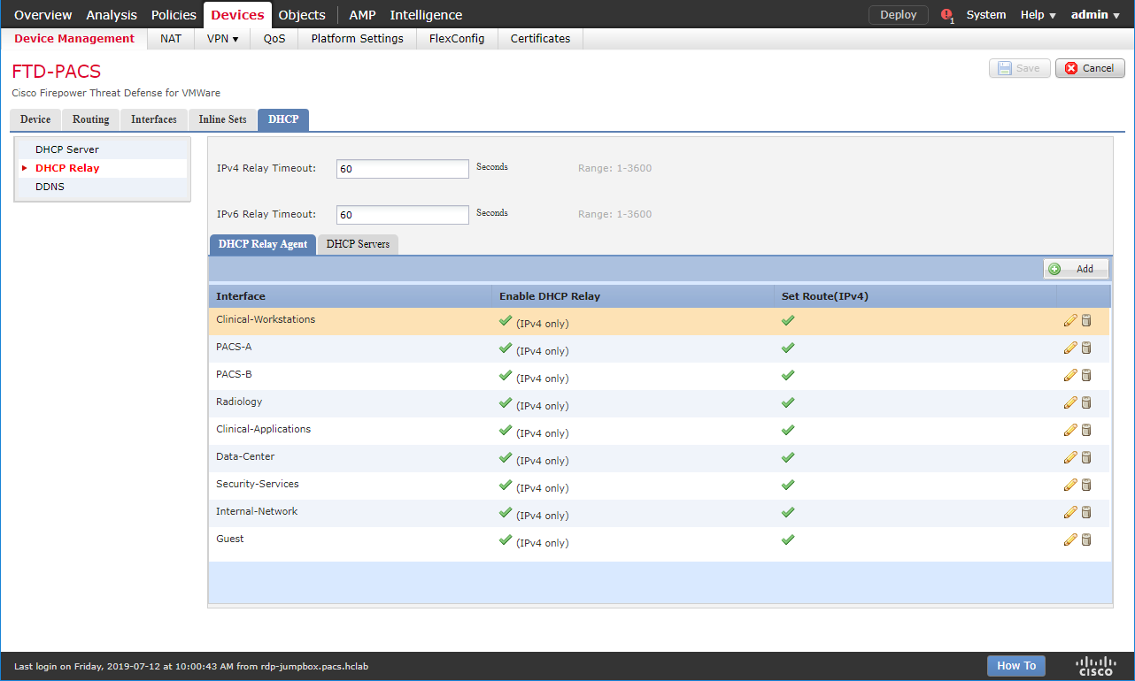
Assign an FTD interface as LAN.
Check the box next to Enable IPv4 Relay.
Check the box next to Set Route.
Click OK.
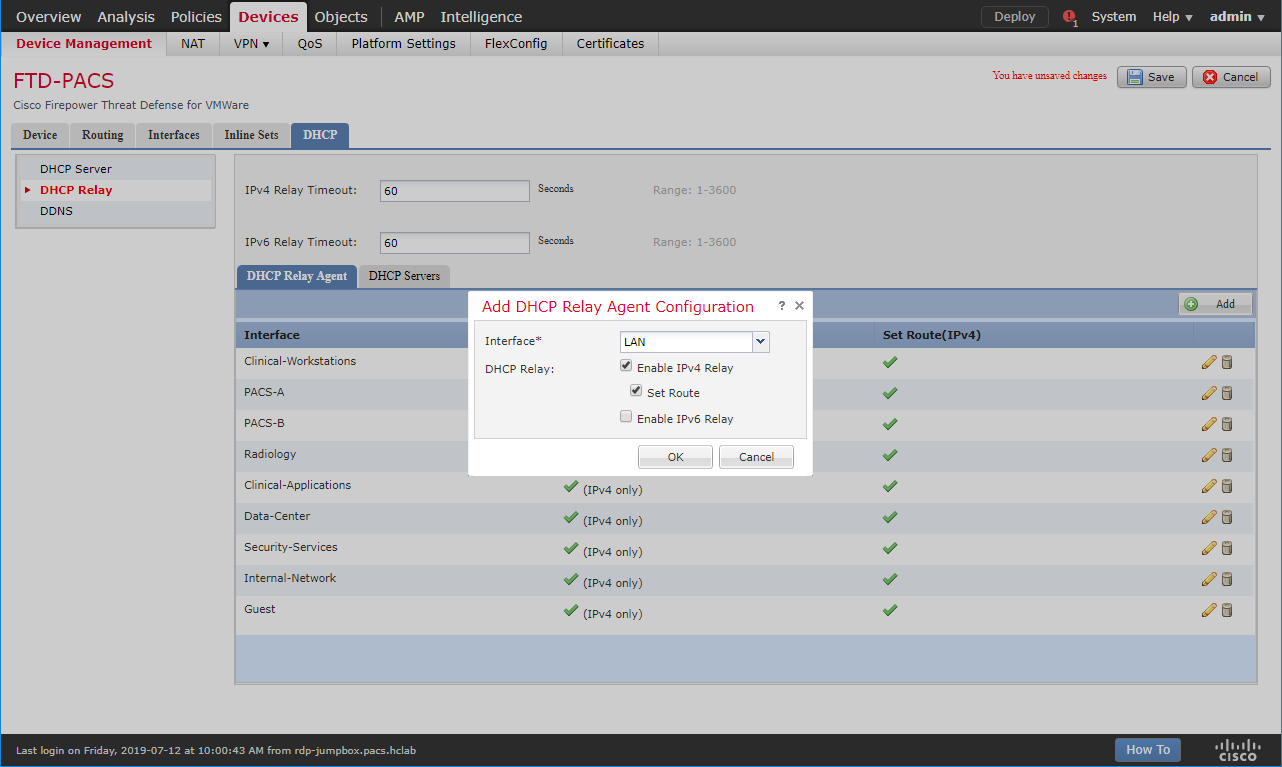
Ensure that the new relay, LAN, is in the DHCP Relay Agent list.
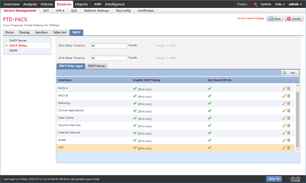
Under DHCP Servers, click Add.
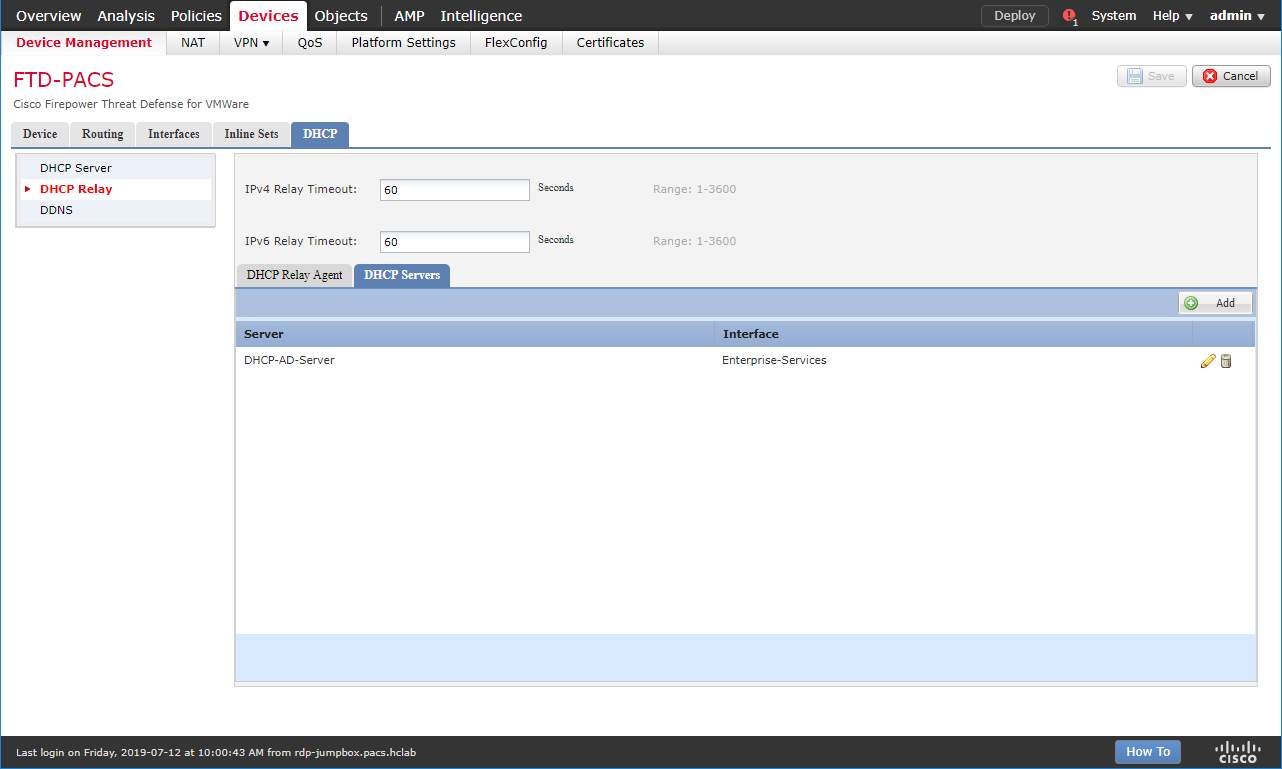
Click the green + button to create a new object for the DHCP server.
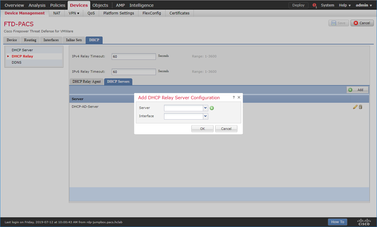
Enter Test-DHCP-Server as a name for the DHCP server.
Enter 192.168.100.170 as an IP address for the DHCP server.
Click Save.
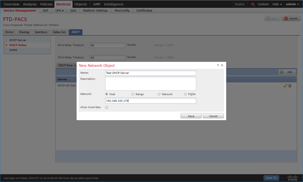
Select the newly created DHCP server.
Select an FTD interface through which the DHCP server can be connected.
Click OK.
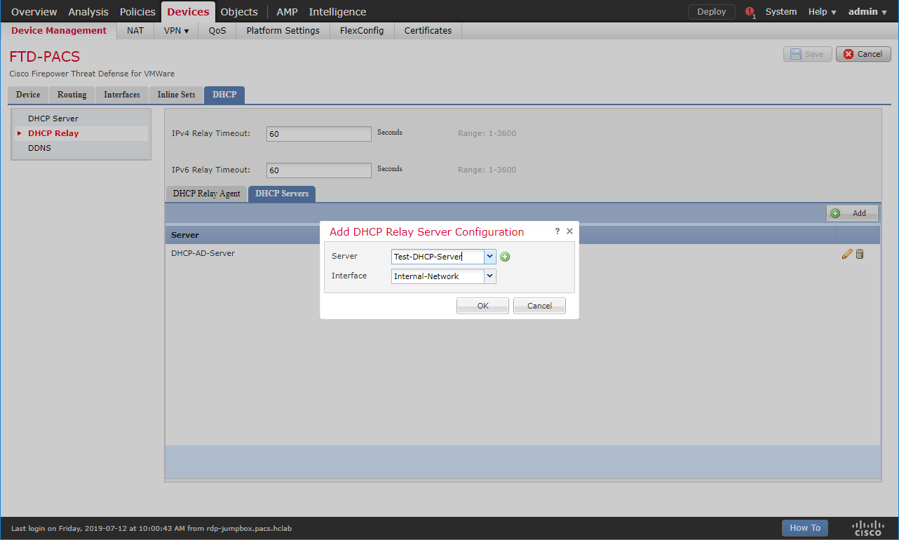
Ensure that the new server is in the DHCP Server list.
Click Save.
Click Deploy to add the new configuration settings to the FTD appliance.
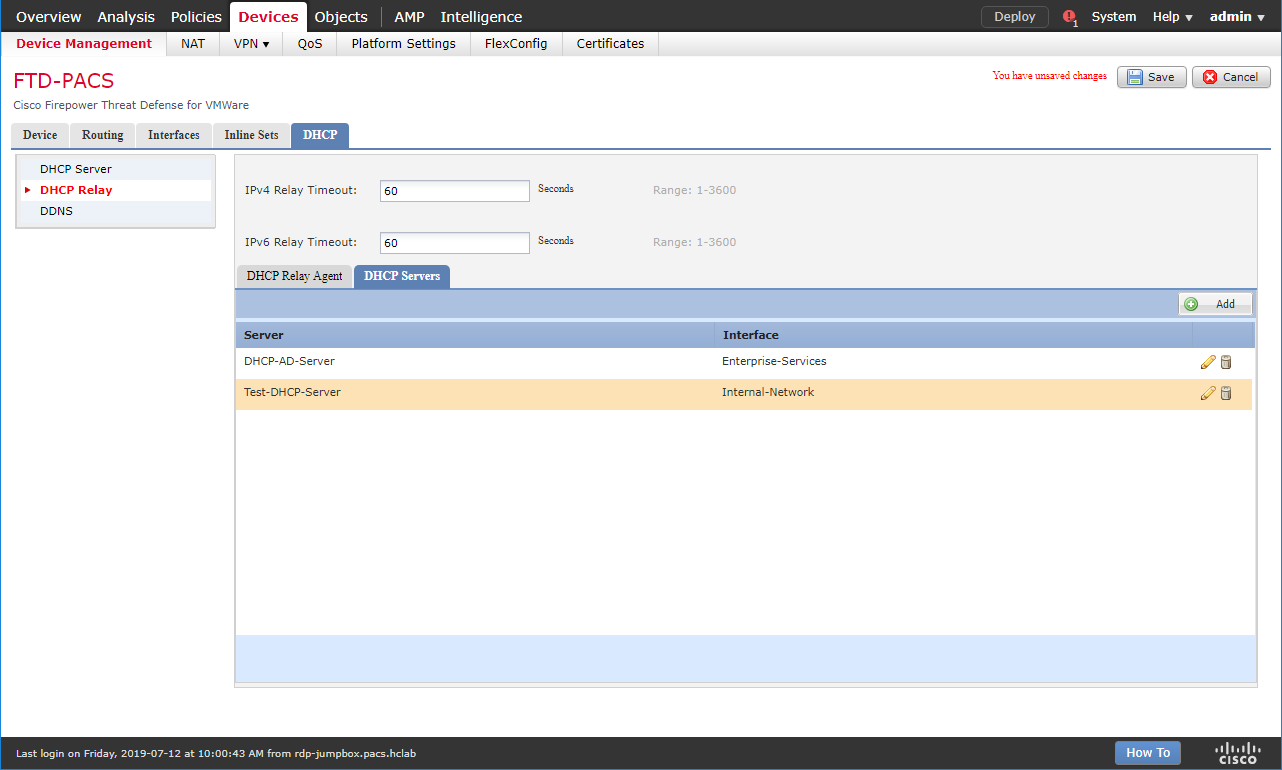
Network Address Translation (NAT) Rules Configuration
Navigate to Devices > NAT.
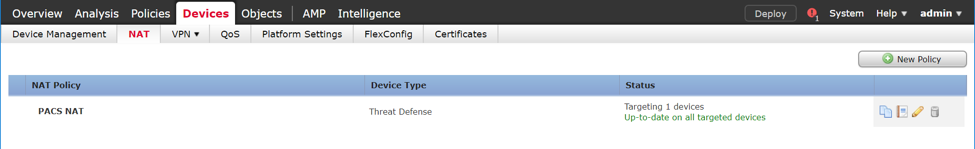
Click New Policy > Threat Defense NAT.
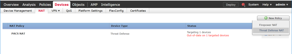
Give the new policy a Name as PACS NAT.
Assign the FTD appliance to the new NAT policy.
Click Save.
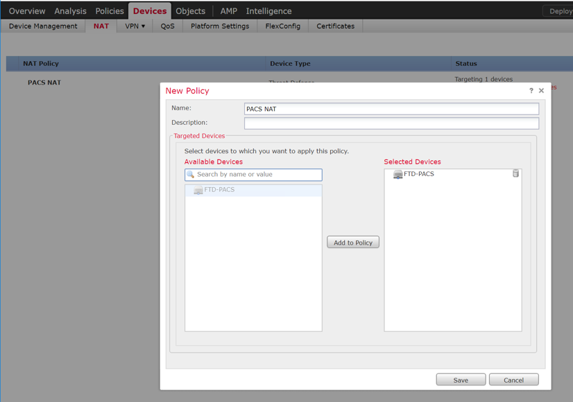
Click the NAT policy’s edit icon.
Click Add Rule.
Set NAT Rule to Auto NAT Rule.
Set Type to Dynamic.
Under Interface Objects, set Source Interface Object to one of the FTD appliance’s LAN interfaces.
Set Destination Interface Object to the FTD appliance’s WAN interface.
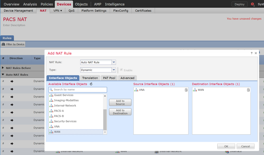
Under Translation, set Original Source to the network that corresponds with the source interface object established in the previous step.
Set Translated Source to Destination Interface IP.
Click OK.
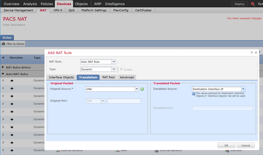
Ensure that the new NAT Rule has been created.
Repeat these steps if needed for each LAN interface attached to FTD appliance.
Click Save.
Click Deploy to add the changes to the FTD appliance.
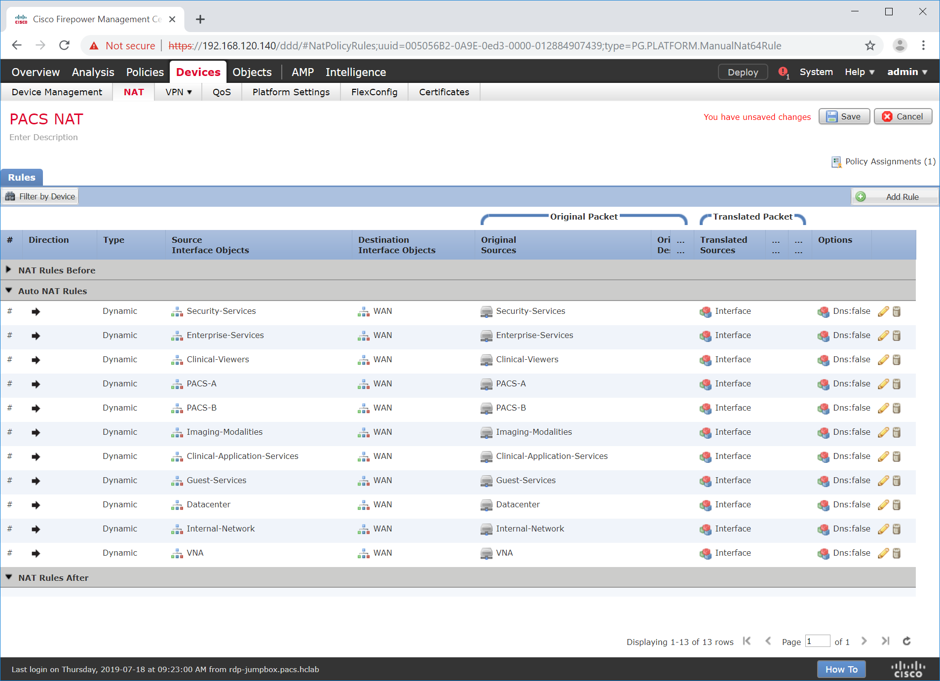
Access Control Policy Through Firepower Management Center Configuration
The Firepower Management Center allows configuration of access-control policies that can then be applied to individual FTD appliances. The purpose of the access-control policy is to create rules that specify how traffic is managed within the network. Each access-control policy contains multiple rules followed by a default action established when the policy is created. For the PACS architecture, one access-control policy was established to manage the traffic on each FTD interface. The steps below describe how the policy and rules were created, as well as how to utilize an intrusion policy with the access-control policy. Additional information on the Cisco Firepower access control list and intrusion prevention configuration is available [C10].
Navigate to Policies > Access Control > Access Control.
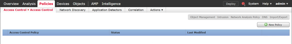
Click New Policy.
Enter PACS Global Policy as the name for the access control policy.
For Select Base Policy, select None.
For Default Action, select Block all traffic.
Add the FTD appliance to the policy.
Click Save.
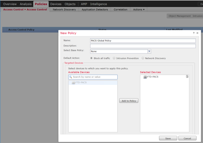
Click the access-control policy’s edit icon.
Note: The policy in the screenshots that follow contains categories created during the process of building the PACS architecture. These categories are not preconfigured.
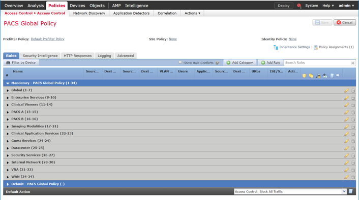
Create a Category
Click Add Category.
Enter PACS as the name for the category.
Insert the category into the Mandatory section.
Click OK.
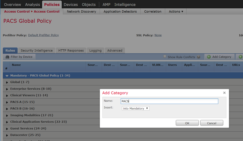
Create a Rule that Allows Application Traffic Between Security Zones
Click Add Rule.
Enter PACS-VNA as the name for the rule.
Insert the rule into the category created in the previous step.
Set Action to Allow.
Note: Because we set the default action to block all traffic when creating the policy, all of the rules we created were set to Allow.
Add security zone(s) to the Source Zone, and add security zone(s) to the Destination Zone.
Note: The two primary methods for adding source and destination networks to an access control rule are through security zones or networks. Security zones are objects that can contain multiple FTD interfaces. Networks can be different types of network objects, including network segments (192.168.1.0/24) or individual devices (192.168.1.1).
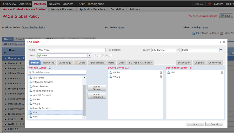
Under Applications, add the application(s) you would like to allow between the specified zones.
Note: This can also be accomplished by specifying the port you would like to allow under the Ports tab. By specifying a specific port, this will open the port to all traffic regardless of the type of traffic (e.g., DICOM) being sent.
Click Add.
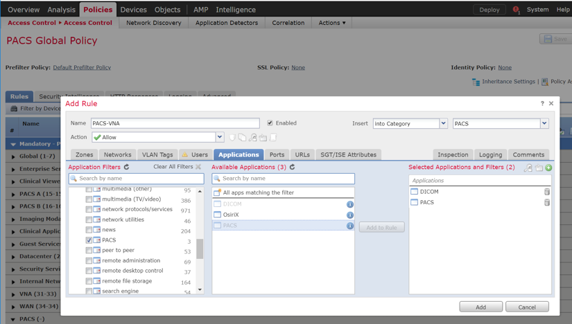
Verify that the Rule has been created.
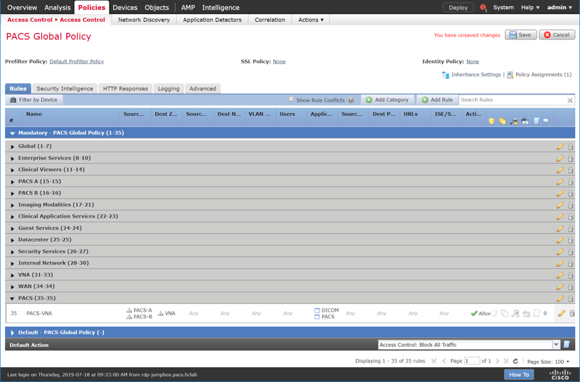
Create a Rule that Allows Traffic on a Specific Port Between Networks
Click Add Rule.
Enter PACS-Internet as the name for the rule.
Insert the rule into the category created previously.
Set Action to Allow.
Under Networks, add a source network(s) and destination network(s).
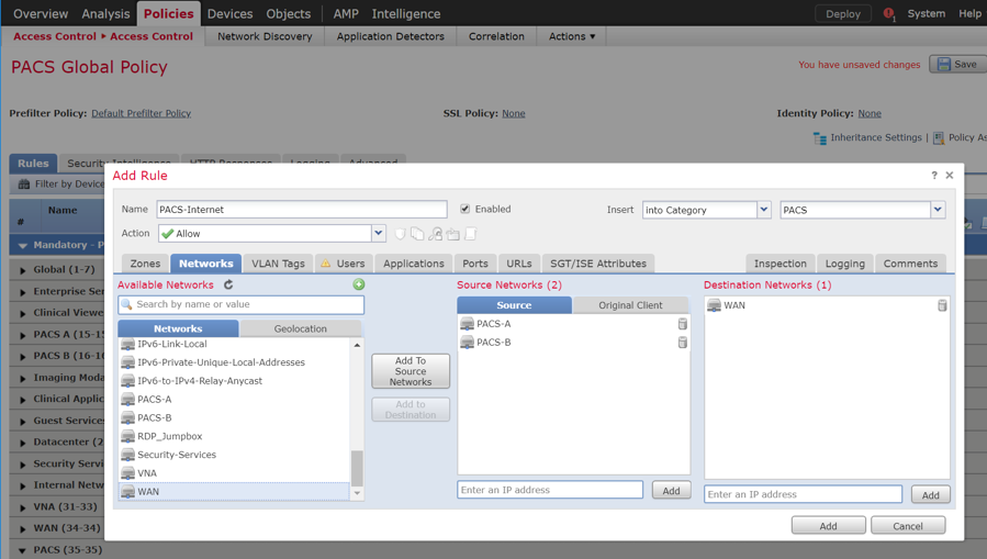
Under Ports, add (a) port(s) to the Selected Destination Ports.
Note: Select from a group of pre-created ports or add your own port by filling out the protocol and port boxes, then click Add under the selected destination ports.
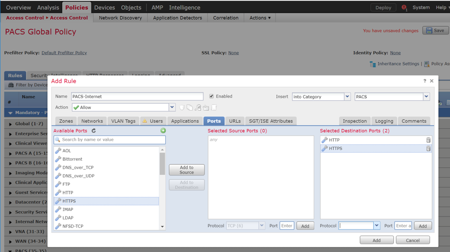
Under URLs, add URL categories that will be allowed (or leave this section blank).
Note: Cisco Firepower generates the URL categories and updates them regularly. Within each URL category, you can specify the reputation level that the URL must meet for the rule to match.
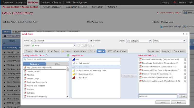
Under Inspection, add an intrusion policy, or leave this section blank.
Note: Intrusion policies are created separately from the access-control policy. Once created, an intrusion policy can be applied to a specific access-control rule or an entire access-control policy. See the link posted [C10] at the beginning of this section for more information on how to create and use intrusion policies in Cisco Firepower.
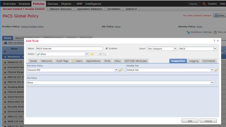
Under Logging, select Log at End of Connection, or leave this section blank.
Note: If logging is enabled, select Event Viewer.
Click Add.
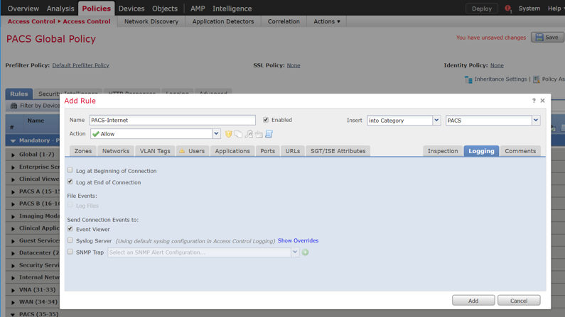
Verify that the access control rules have been created and placed in the proper category.
Click Save.
Click Deploy to add changes to the FTD appliance.
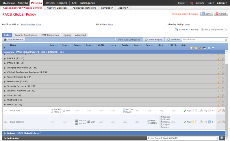
2.7.2 Cisco Stealthwatch
Cisco Stealthwatch provides network visibility and analysis through network telemetry. It provides threat detection and remediation as well as network segmentation using machine learning and behavioral modeling. This project integrates Cisco Stealthwatch with Cisco Firepower to allow Cisco FTD to send NetFlow directly to Stealthwatch for analysis.
Cisco Stealthwatch Management Console Appliance Information
CPUs: 3
RAM: 16 GB
Storage: 60 GB (thin provision)
Network Adapter 1: VLAN 1901
Operating System: Linux
Cisco Stealthwatch Management Console Virtual Edition Installation Guide
Install the Cisco Stealthwatch Management Console appliance according to the instructions detailed in the Cisco installation guide [C11].
Cisco Stealthwatch User Datagram Protocol (UDP) Director Appliance Information
CPU: 1
RAM: 4 GB
Storage: 60 GB (thin provision)
Network Adapter 1: VLAN 1901
Network Adapter 2: VLAN 1901
Operating System: Linux
Cisco Stealthwatch UDP Director Virtual Edition Installation Guide
Install the Cisco Stealthwatch UDP Director appliance according to the instructions provided in the Cisco installation guide [C11].
Cisco Stealthwatch Flow Collector Appliance Information
CPUs: 2
RAM: 16 GB
Storage: 60 GB (thin provision)
Network Adapter 1: VLAN 1901
Operating System: Linux
Cisco Stealthwatch Flow Collector Virtual Edition Installation Guide
Install the Cisco Stealthwatch Flow Collector appliance according to the instructions provided in the Cisco installation guide [C11].
Configure NetFlow Parameters for Cisco Firepower
Log in to the Cisco Firepower Management Console.
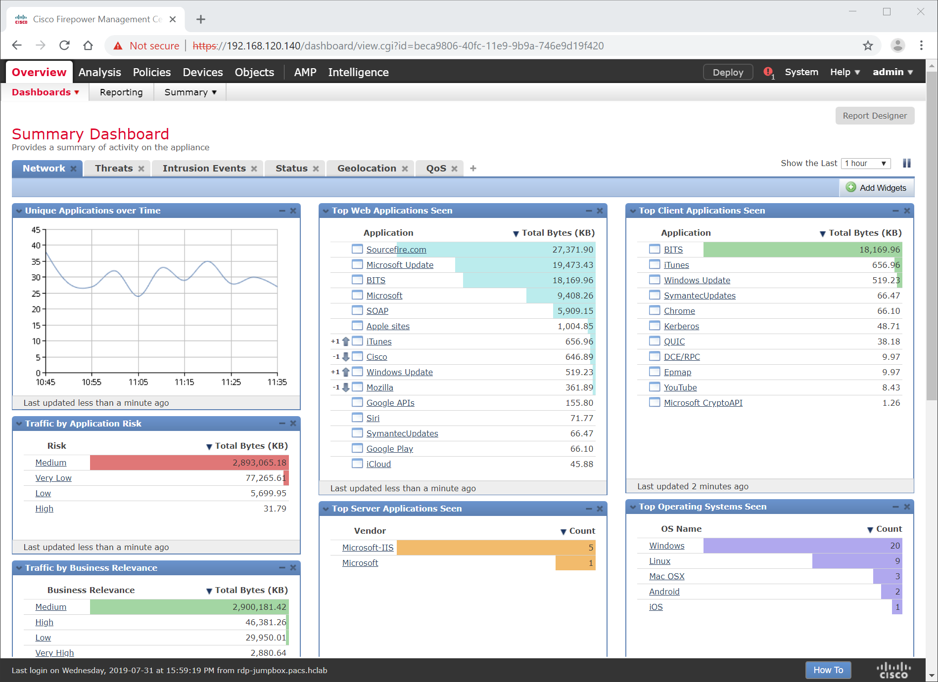
Navigate to Objects.
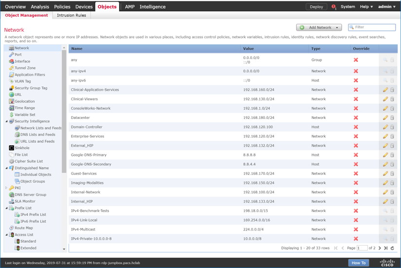
Navigate to FlexConfig > Text Object.
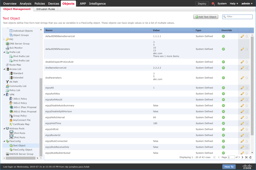
Under the Name column, find netflow_Destination.
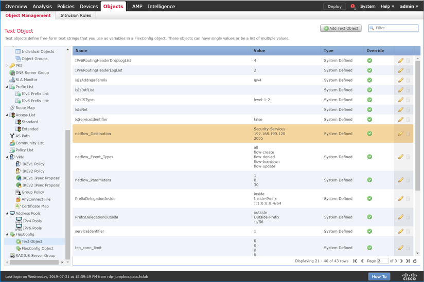
Click the edit icon for netflow_Destination.
Set Variable Type to Multiple.
Set Count to 3.
For Row 1, enter Security-Service to set the name of the Cisco FTD interface to which the Cisco Stealthwatch UDP appliance is connected.
For Row 2, enter 192.168.190.120 to set the IP address of the Cisco Stealthwatch UDP appliance.
For Row 3, enter 2055 to set a port from which the Cisco Stealthwatch UDP appliance will receive NetFlow traffic.
Click Save.
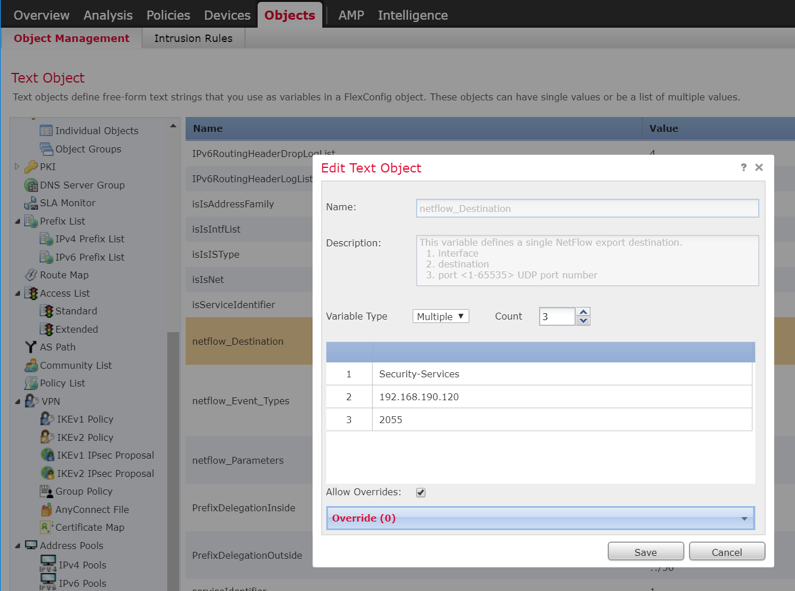
Under the Name column, find netflow_Parameters.
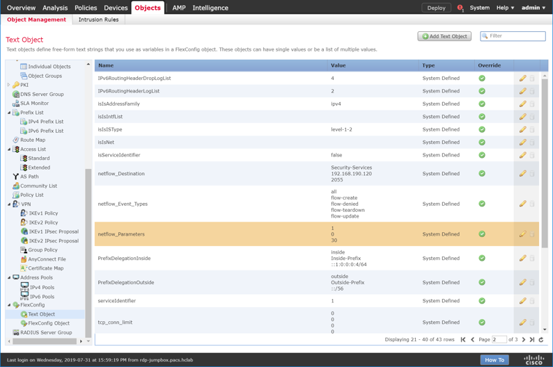
Click the edit icon for netflow_Parameters.
Set Variable Type to Multiple.
Set Count to 3.
For Row 1, enter 1 as a number for minutes between flow update events.
For Row 2, enter 0 as a number for seconds to delay flow create.
For Row 3, enter 30 as a number for minutes for template time-out rate.
Click Save.
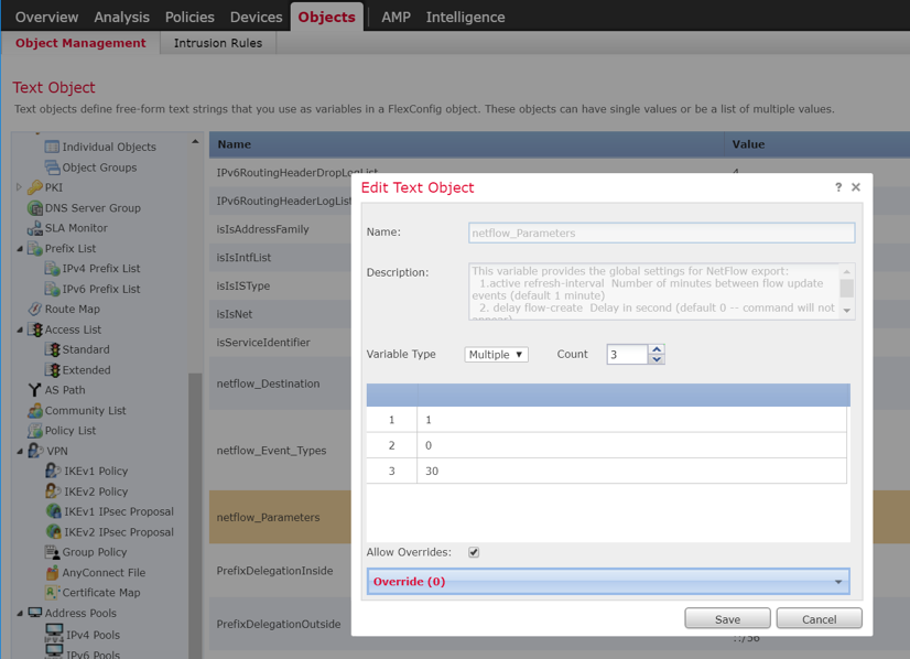
Navigate to Devices > FlexConfig.
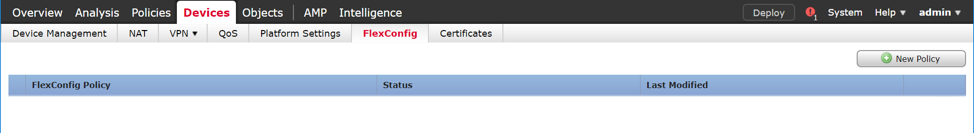
Click New Policy.
Enter a Name (e.g., Netflow) for the policy.
Under Selected Devices, add the Cisco FTD.
Click Save.
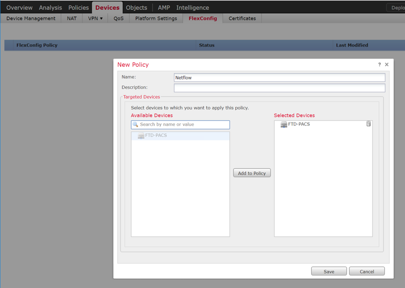
Click the edit icon for the new policy.
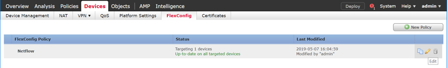
Under Available FlexConfig, find Netflow_Set_Parameters, and add it to Selected Append FlexConfigs.
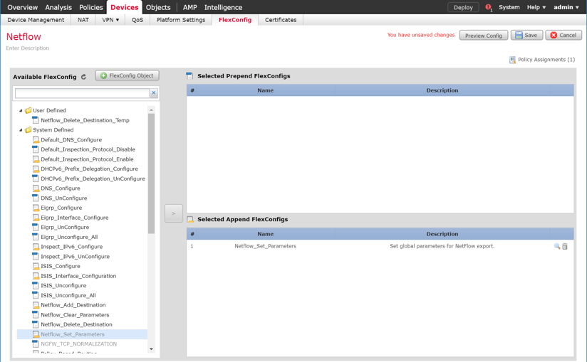
Click the magnifier icon for Netflow_Set_Parameters.
Under Variables > Default Value, verify the minutes between flow data events, seconds to delay flow create, and minutes for template time-out rate that were set for netflow_Parameters.
Click Close.
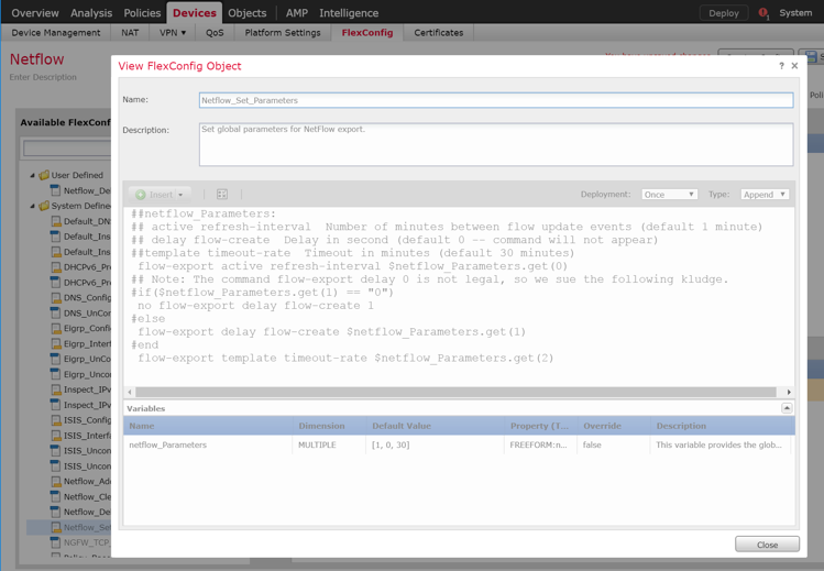
Under Available FlexConfig, find Netflow_Add_Destination, and add it to Selected Append FlexConfigs.
Click the magnifier icon for Netflow_Add_Destination.
Under Variables > Default Value, verify the Cisco FTD interface name, IP address of the Cisco Stealthwatch, and the NetFlow traffic port.
Click Close.
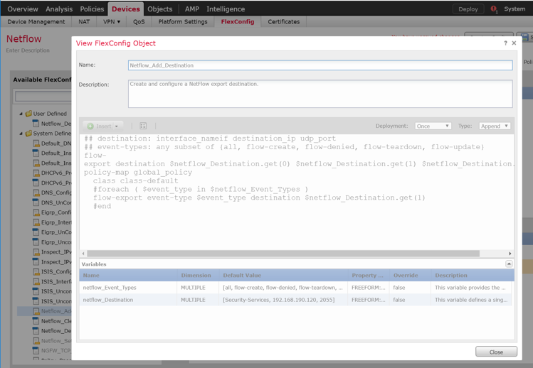
Click Save.
Deploy changes to the Cisco FTD.
Forwarding Rules for Cisco Stealthwatch UDP Configuration
Log in to the web dashboard of the Cisco Stealthwatch Management Console.
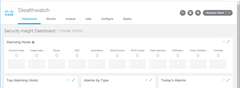
Navigate to Settings > Central Management.
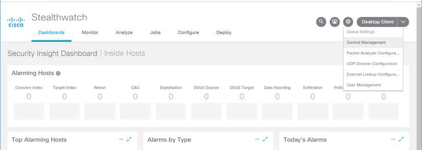
Click the ellipsis for the Cisco Stealthwatch UDP appliance and select Edit Forwarding Rules.
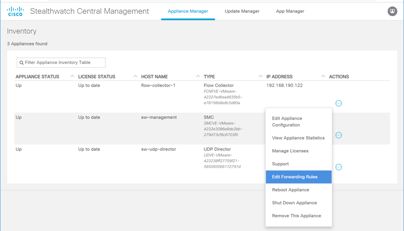
Click the ellipsis for the Cisco Stealthwatch UDP appliance, select Configure Forwarding Rules.
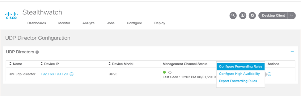
Under Forwarding Rules, select Add New Rule.
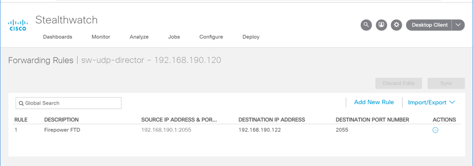
Enter a description (e.g., Firepower FTD) for the rule.
For source IP address and source port, enter the IP address and port (e.g., 192.168.190.1:2055) of the Cisco FTD interface sending the NetFlow traffic.
Note: These parameters were established in Cisco FTD, found in the previous section, for the netflow_Destination object.
For destination IP address, enter the IP address (e.g., 192.168.190.122) of the Cisco Stealthwatch Flow Collector.
For destination port, enter the port (e.g., 2055) of the Cisco Stealthwatch Flow Collector.
Note: This port was configured during setup of the Flow Collector.
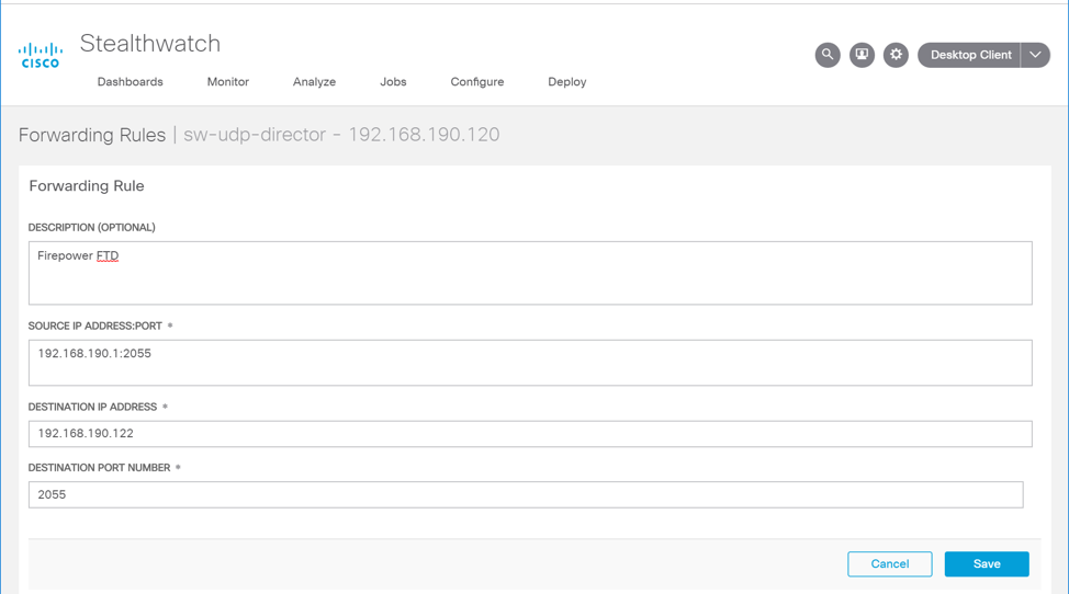
On the Cisco Stealthwatch Management Console dashboard, view the Flow Collection Trend graph to verify that the Cisco Stealthwatch Flow Collector is receiving packets from the Cisco Stealthwatch UDP.
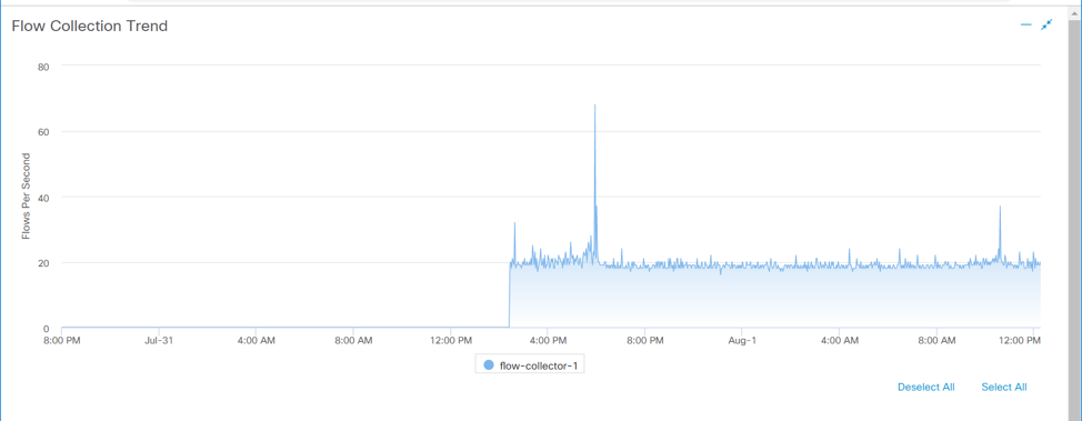
2.7.3 Tempered Networks Identity Defined Networking (IDN)
Tempered Networks IDN provides cryptographically defined host identifiers using the HIP protocol rather than IP addressing. Network traffic traverses an overlay network using HIPswitches that effectively cloak that traffic from the production network. A notional architecture appears in Figure 2‑2 below.
Figure 2‑2 Architecture of Networks IDN
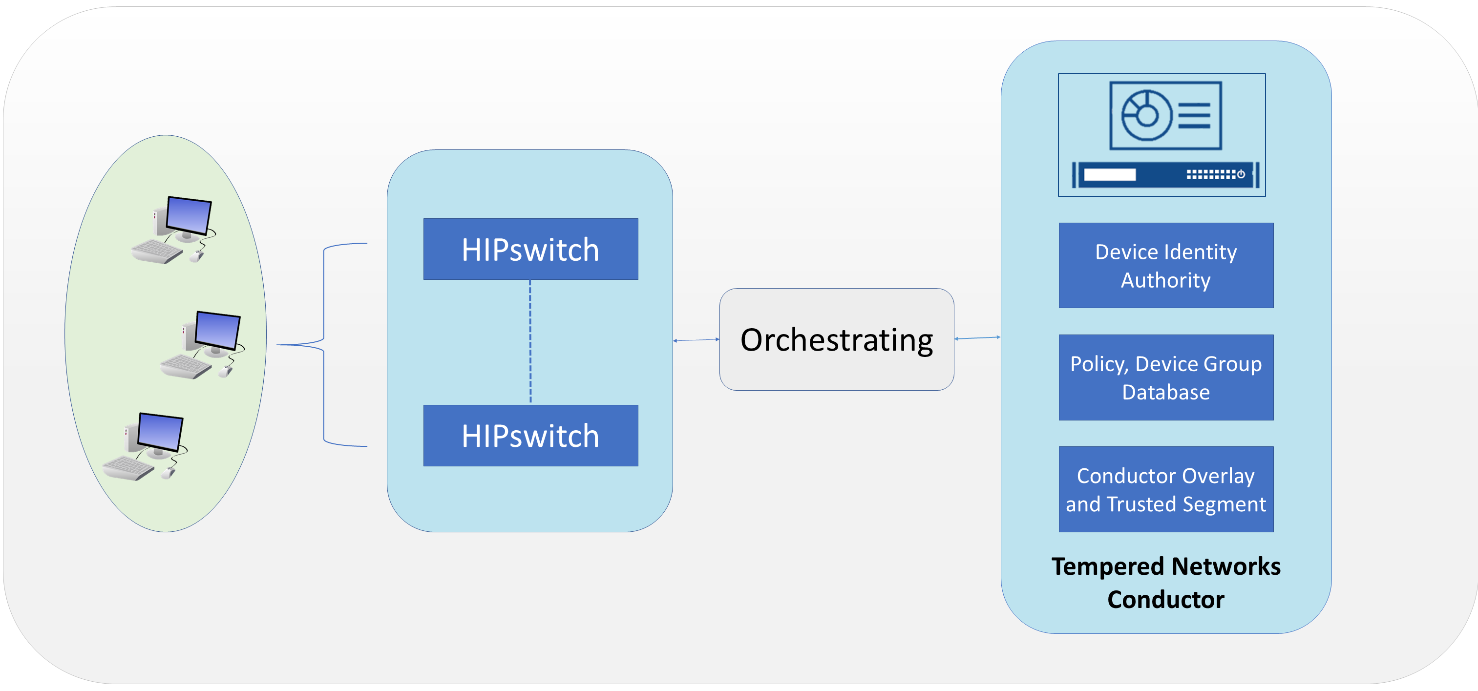
Tempered Networks Conductor is the orchestration engine and intelligence behind an IDN. As shown in the above figure, the Conductor is responsible for creating and executing security policies and overlays. It is also responsible for issuing unique cryptographic IDs to the IDN end points that enforce explicit trust relationships through device-based allow-listing.
HIPswitches are typically deployed in front of devices or hosts that cannot protect themselves, like medical devices such as modalities and other legacy systems and machines, or when customers are unable to install the proper endpoint-protection applications.
Installation involves deployments of the Tempered Networks Conductor and HIPswitches. Tempered Networks provided a conductor open virtual appliance or application (OVA) file and a HIPswitches OVA file.
2.7.3.1 Conductor Installation
System Requirements
CPUs: 4
Memory: 4 GB RAM
Storage: 120 GB
Operating System: Linux Red Hat
Network Adapter: VLAN 1201
Tempered Networks Conductor Installation
Log in to the vSphere Client.
Select File > Deploy OVF Template.
Respond to the prompts with information specific to your deployment, including the ova package location, name and location, storage, networking, and provisioning.
Click Power On After Deployment, and click Finish.
Once the installation is done, power on the Conductor server, and log in with username macinfo and the corresponding password to set up the necessary MAC address and IP address.
2.7.3.2 HIPswitch Installation
System Requirements
CPUs: 4
Memory: 1 GB RAM
Storage: 1 GB
Operating System: Linux Red Hat
Network Adapter: VLAN 1201
HIPswitch Installation
Log in to the vSphere Client.
Select File > Deploy OVF Template.
Respond to the prompts with information specific to your deployment, including the ova package location, name and location, storage, networking, and provisioning.
Click Power On After Deployment, and click Finish.
After the installation, use the username and password to connect the HIPswitch to the conductor.
Use the username underlayaddress and its corresponding password to set up the IP address, netmask, gateway, and DNS for the HIPswitch.
Repeat the above installation procedures to install additional HIPswitches.
Tempered Networks Conductor and HIPswitch Configuration
Configuration for the Conductor and HIPswitches is done through the browser connected to the Conductor https://ConductorIP. The login page appears below.
Enter the username and password to open the dashboard.
Click the Settings tab.
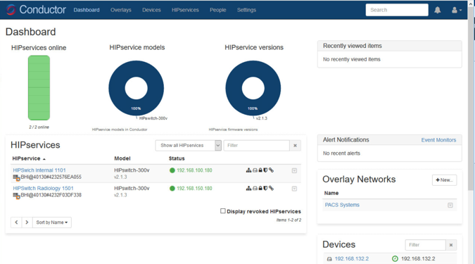
From this page, you can set up the license and perform the system setup. Click the Setup button to enter the system setup.
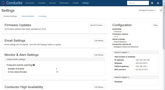
Enter the proper network parameters for the Conductor, including the IP address (e.g., 192.168.120.180), Netmask (e.g., 255.255.255.0), Default gateway (e.g., 192.168.120.1), and DNS (e.g., 8.8.8.8, 4.4.8.8), then click Configure.
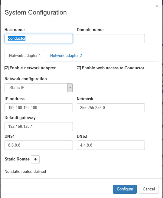
An overlay is configured to support the micro-segmentation. Click the Overlay tab to open the following page and add a new overlay by clicking the + New Overlay Network… The screenshot below shows a configured overlay called PACS Systems.
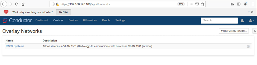
Two HIPswitches were installed to test for this project. These two HIPswitches are Model HIPswtich-300v, and they are named HIPswitch Internal and HIPswitch Radiology. Both were configured to participate in the PACS Systems overlay network.
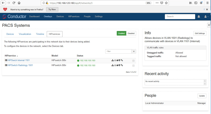
Two special VLANs were created for each of these two HIPswitches under PACS Systems overlay:
VLAN 1302 for HIPswitch Internal 1101
VLAN 1303 for HIPswitch Radiology 1501
Devices to be protected under the HIP network will be connected to these two HIPswitches through the VLANs:
PACS servers are connected to VLAN 1302 under the HIPswitch Internal 1101.
Medical imaging devices are connected to VLAN 1303 under the HIPswitch Radiology 1501.
After creating a secure layer in the Conductor and adding those medical imaging devices and PACS servers to that layer, the medical imaging device and PACS server can be set up as trusted by selecting the Enable button on the overlay page. Once they are trusted, communication between those medical imaging devices and PACS servers will be established. All the communication will be encrypted.
The microsegmentation is achieved by using the HIPswitch. Other VMs will not be able to communicate with these two devices unless they are configured to do so.
2.7.4 Zingbox IoT Guardian
Zingbox IoT Guardian consists of two separate components that work together to monitor and analyze network traffic. The first component is a cloud-based platform called Zingbox Cloud, which aggregates and analyzes data to provide insights into the devices on the local network. The second component is Zingbox Inspector, a local appliance that receives network flows from devices on the local network and sends specific metadata to Zingbox Cloud for further analysis.
Zingbox Cloud Setup
Visit https://zingbox.com and register for an account.
Log in to the Zingbox console and navigate to Administration > My Inspectors > Download Inspector.
Download either the .ova or the .iso file, depending on your environment’s requirements.
System Requirements
CPUs: 4
Memory: 8 GB RAM
Storage: 256 GB (thin provision)
Operating System: CentOS 7
Network Adapter 1: VLAN 1101
Network Adapter 2: Trunk Port
Zingbox Inspector Installation
Create a new virtual machine, and under configuration, select Typical.
Click Next >.
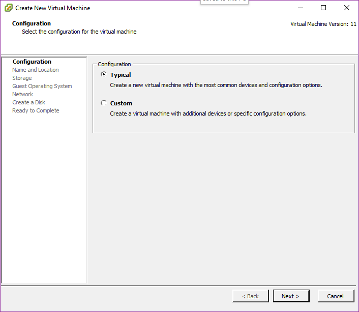
Create a Name for the virtual machine and assign it an Inventory Location.
Click Next >.
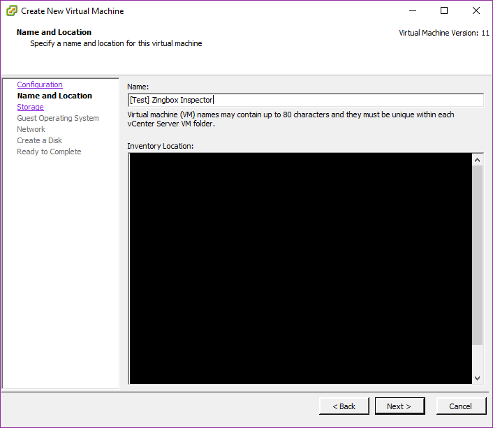
Select a destination storage for the VM.
Click Next >.
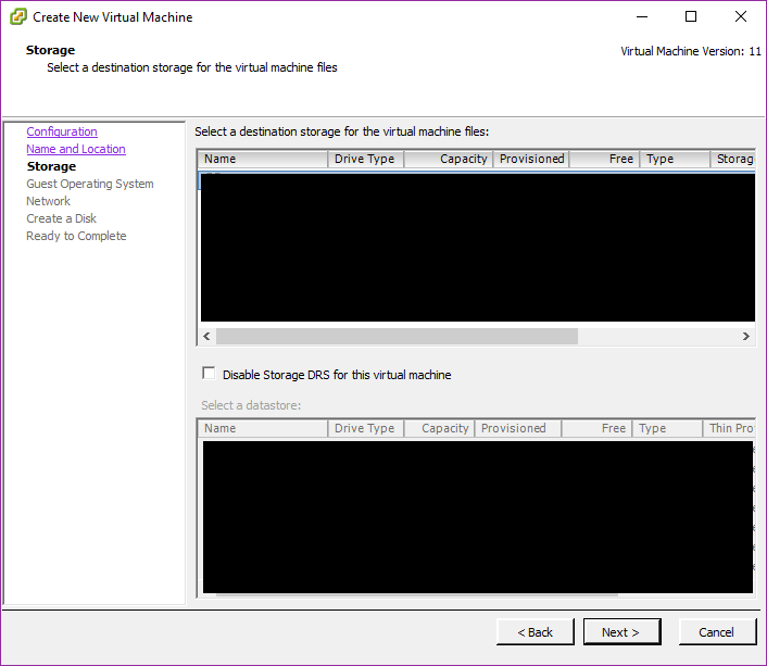
Check Linux and set the version to CentOS 4/5/6/7 (64-bit).
Click Next >.
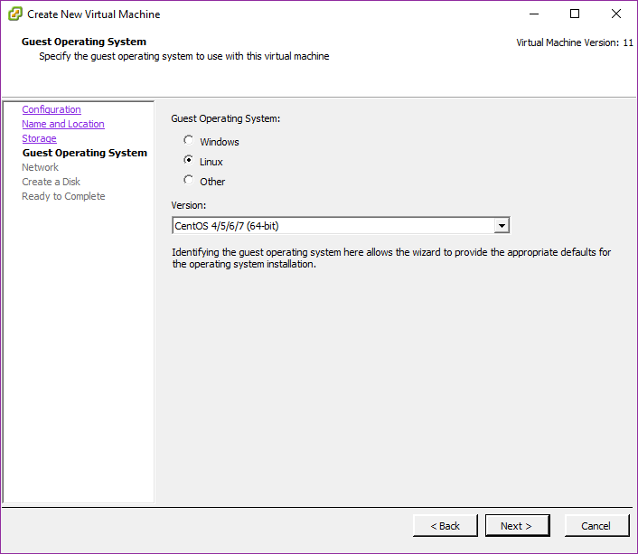
Connect 2 NICs to the virtual machine and assign them to a network.
Check Connect at Power On for both NICs.
Click Next >.
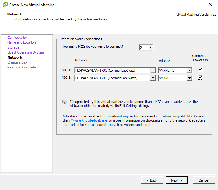
Set a Virtual disk size and Provisioning method.
Click Next >.
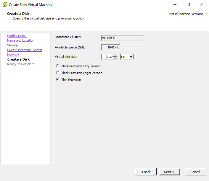
Verify that virtual machine settings are correct.
Check Edit the virtual machine settings before completion.
Click Continue.
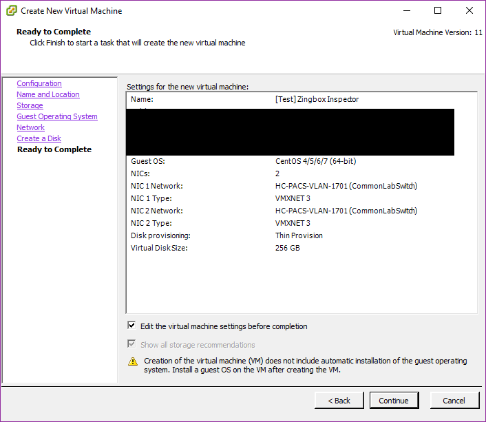
Set memory to 8 GB.
Set CPUs to 4.
Under New CD/DVD (adding), set these parameters:
Check Connect at power on.
Select Datastore ISO File, then browse for the ZingOS.iso file in your data store.
Click Finish.
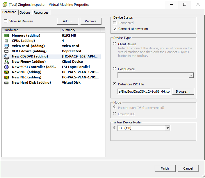
Connect to the inspector console and follow the onscreen prompts to finish the configuration.
In a web browser, enter the URL of your Zingbox Cloud instance.
Enter your Zingbox Cloud credentials.
Click Login.
On the home page, navigate to Administration > My Inspectors.
Verify that the host name of the Zingbox Inspector set up previously is visible and connected (shown by the green cloud icon).
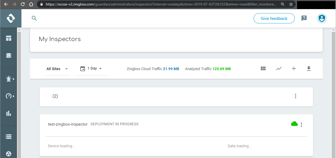
2.7.5 Forescout CounterACT 8
Forescout CounterACT is a network access control tool that can perform device discovery and classification, risk assessment, and control automation through passive and active techniques. For this project, the intended use of Forescout is to manage device compliance and perform necessary remediation when devices fall out of compliance.
System Requirements
CPUs: 2
Memory: 8 GB RAM
Storage: 80 GB (thin provision)
Operating System: Linux Kernel 3.10
Network Adapter 1: VLAN 1201
Network Adapter 2: Trunk Port
Forescout Appliance Installation
To begin installation, obtain the Forescout ISO file. Load the Forescout ISO file into the VM’s compact disc/digital versatile disc (CD/DVD) drive. Make sure the CD/DVD drive is set to Connect at Power On.
Boot up the VM and begin the installation process.
Select Install CounterACT.
Press Enter to reboot.
Select option 1 to configure CounterACT.
Select option 1 for standard installation.
Press enter to proceed.
Select option 1 for CounterACT Appliance.
Select option 1 for Per Appliance Licensing Mode.
Enter appliance description.
Give appliance a password.
Enter ForescoutCA and apply this as the appliance host name.
Assign the appliance IP address 192.168.120.160.
Assign appliance network mask 255.255.255.0.
Enter 192.168.120.1 as the appliance’s gateway.
Enter domain name ********
Enter DNS server address 192.168.120.100.
Review configuration and run test.
Once the test passes, select done.
Forescout CounterACT Console Installation
Run Install_Management.exe.
Click Next >.
Verify Installation Directory as C:\Users\Administrator\ForeScout CounterACT 8.0.1; click Next >.
When the Ready to Install screen appears, click Next > to begin the installation process.
- An Installing screen will appear that provides a status bar indicating the degree of installation completion. Click the Next > button to allow the
installation to proceed.
As the installation nears completion, a screen indicating Completing the ForeScout 8.0.1 Setup Wizard displays. Check Create Desktop shortcut; then click Finish.
Launch Forescout CounterACT Console, and enter the information that follows, then click Login:
Enter 192.168.120.160 in the IP/Name text box.
Select Password as the Login Method.
Enter Administrator in the User Name text box.
Enter the password in the Password box.
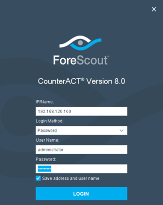
Forescout CounterACT Configuration
To use the full function offered by the Forescout CounterACT, proper network configuration is required, which may include the monitor and response interface assignments at the data center, the network VLAN and segmentation information, the IP address range that the CounterACT appliance will protect, user directory account information, domain credentials, the core switch IP address, and vendor and Simple Network Management Protocol parameters.
After completing the installation, log in to the CounterACT Console by using the steps below:
Select the CounterACT icon from the server on which you installed the CounterACT Console. A logon page displays, as depicted below.

Provide the following information, and select Login to open the console:
Enter the IP address 192.168.120.160 in the IP/Name field.
In the User Name field, enter admin.
In the Password field, enter the admin password, which is defined during the installation.
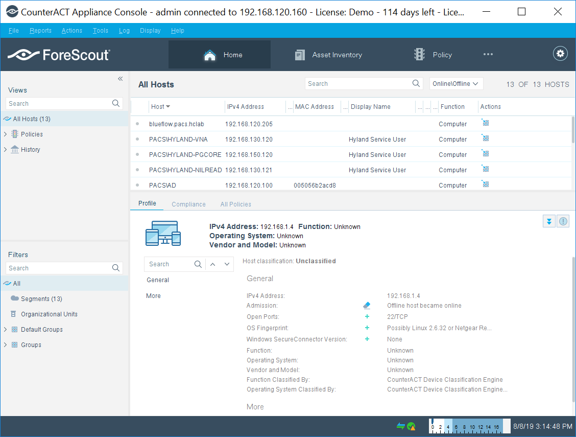
The console manager can be used to view, track, and analyze network activities detected by the appliance. It can also be used to define the threat protection, firewall, and other polices.
The figure below shows the sample asset inventory page. (Further network configuration will be needed for complete inventory information.)
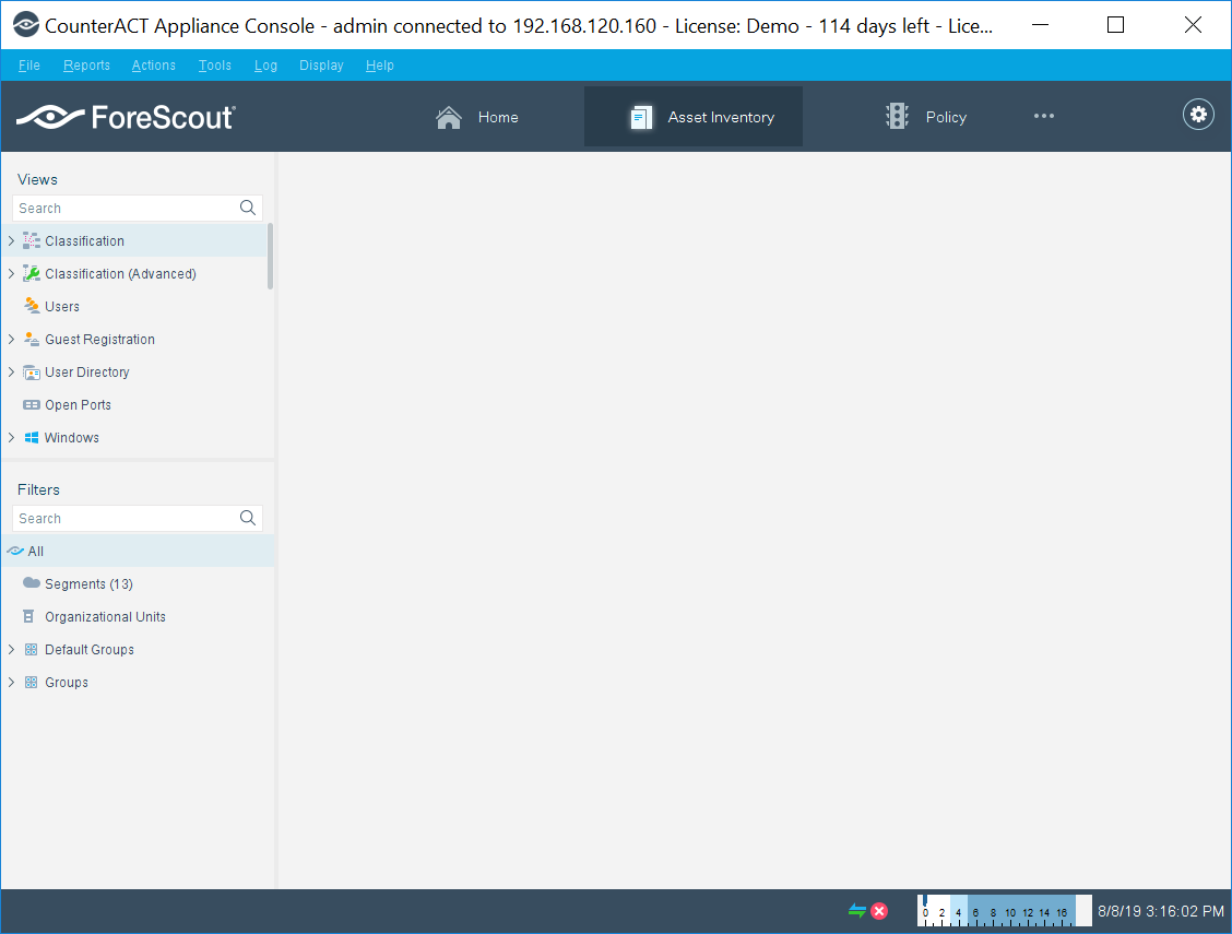
The figure below shows the sample Policy Manager page. Further network configuration and policy definition will be needed for complete policy information.
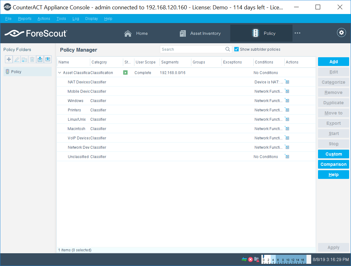
2.7.6 Symantec Endpoint Detection and Response (EDR)
Symantec Endpoint Detection and Response performs behavioral analytics on endpoint events from Symantec Endpoint Protection to identify potentially malicious behavior. It can sandbox impacted endpoints, prioritize risks, and provide tailored remediation guides.
System Requirements
CPUs: 12
Memory: 5 GB RAM
Storage: 500 GB (thin provision)
Operating System: CentOS 7
Network Adapter 1: VLAN 1901
Network Adapter 2: SPAN_PACS
Symantec EDR Installation
Launch the virtual appliance after deployment of the vendor-provided SEDR-4.0.0-483-VE.ova file.
Enter default username admin and default password. You will be required to change the default password by entering a new password.
After changing the default password, the bootstrap will automatically launch. Enter the following options during the bootstrap:
IPv4 address []: 192.168.190.17
IPv4 netmask []: 255.255.255.0
Gateway []: 192.168.190.1
Name server (IPv4) []: 192.168.120.100
Configure another nameserver? [y/n]: n
Configure IPv4 static routes? [y/n]: n
What do you want to call this device?: EDR
Set NTP server []: X.X.X.X
After verifying the correct details, enter Y to save changes. The appliance will restart.
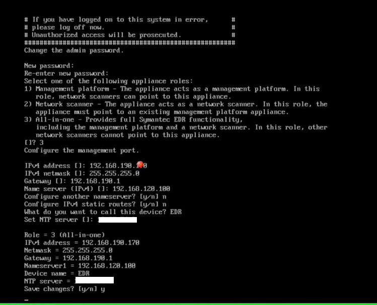
Open a web browser, and travel to the virtual appliance at https://192.168.190.170. Enter the username setup and password *****.
Follow the prompts to create the initial admin account.
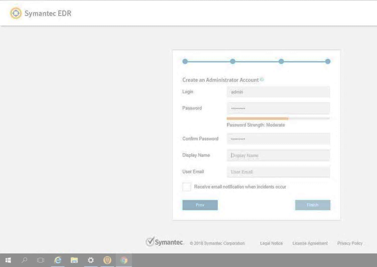
Select the Settings menu, and then select the Global submenu.
Ensure Enable Symantec Endpoint Protection Correlation is checked.
Select Add SEPM Database.
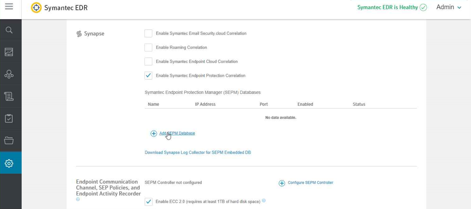
Provide the information that follows, and click Save:
DB Type: Embedded DB
Entry Name: SEPM
Address: 192.168.190.172
Port: 8081
Connection Password: Enter your connection password.
Enabled: checked
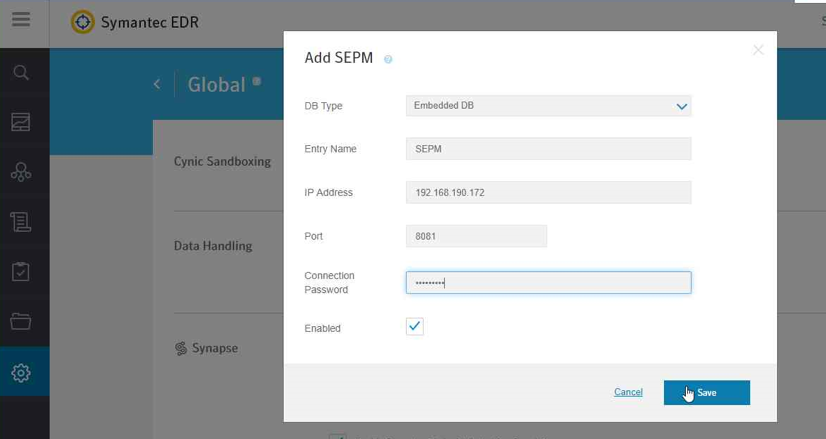
After completing the integration with SEPM, select the Settings menu, then select the Appliances submenu.
Select Edit Default Appliance.
Select Add Internal Network to create and add a Subnet, Netmask, and Description for each internal network listed below. Make sure to save after entering the network details.
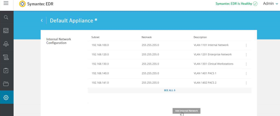
Subnet: 192.168.100.0 Netmask: 255.255.255.0 Description: VLAN 1101
Subnet: 192.168.120.0 Netmask: 255.255.255.0 Description: VLAN 1201
Subnet: 192.168.130.0 Netmask: 255.255.255.0 Description: VLAN 1301
Subnet: 192.168.140.0 Netmask: 255.255.255.0 Description: VLAN 1401
Subnet: 192.168.141.0 Netmask: 255.255.255.0 Description: VLAN1402
Subnet: 192.168.150.0 Netmask: 255.255.255.0 Description: VLAN 1501
Subnet: 192.168.160.0 Netmask: 255.255.255.0 Description: VLAN 1601
Subnet: 192.168.180.0 Netmask: 255.255.255.0 Description: VLAN 1801
Subnet: 192.168.190.0 Netmask: 255.255.255.0 Description: VLAN 1901
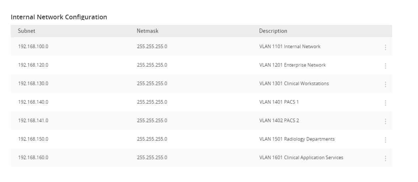
Select Settings and then Global.
Uncheck Enable ECC 2.0 under Endpoint Communication Channel, SEP Policies, and Endpoint Activity Recorder.
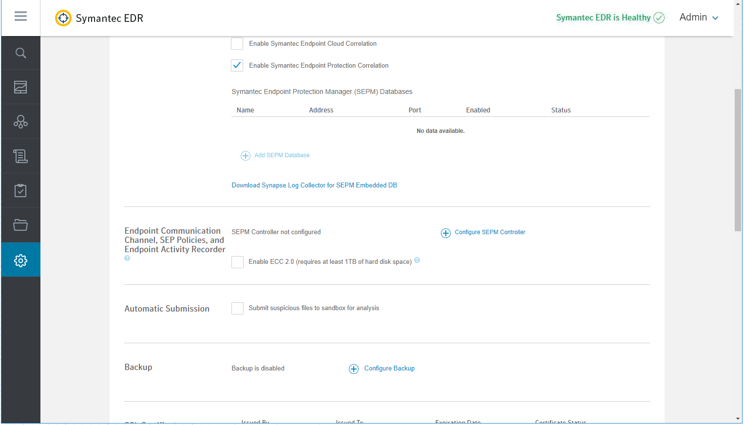
Select Settings and then Appliances.
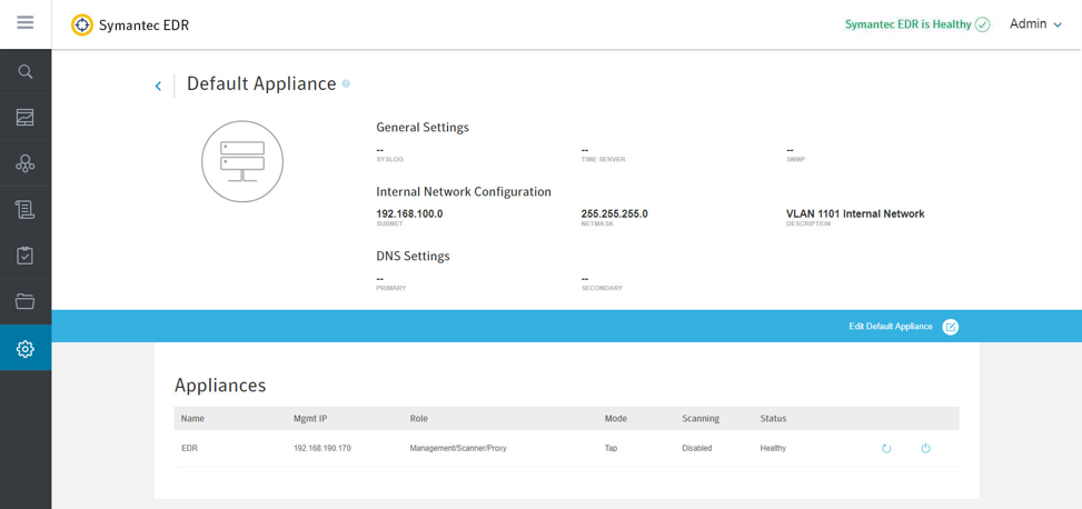
Select EDR from the appliances list.
Turn on Scanning under the Network Interface Settings.
Symantec EDR and SEP Correlation
Open a web browser and navigate to the virtual appliance at https://192.168.190.170. Log in with your administrator account.
From the settings menu, select global settings.
Select Download Synapse Log Collector for SEPM Embedded DB.
After the SEPMLogCollector.msi finishes downloading, move to the SEP Manager (SEPM).
Launch the SEPMLogCollector.msi file from SEPM.
Continue through the setup wizard prompts by clicking Next to use the default settings.
After installation is complete, launch the Log Collection for SEPM embedded DB configuration utility, and enter the values below:
Service Hostname (optional): Leave blank.
Service IP address: 192.168.190.172
Service port: 8082
Log Collector connection password: Enter connection password.
Confirm connection password: Enter connection password again.
SEPM embedded database configuration password: Enter the embedded DB password.
After entering values into the configuration utility, click Confirm.
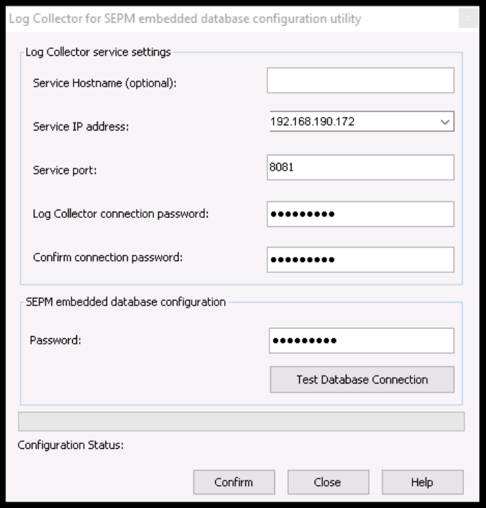
2.8 Endpoint Protection and Security
Endpoint protection and security measures are deployed to workstation end points to further emphasize defense in depth. The build includes an agent-based endpoint protection solution that is centrally managed within the enterprise. Endpoint protection provides anti-malware features with centralized servers assuring that managed assets receive regular updates.
2.8.1 Symantec Data Center Security: Server Advanced (DCS:SA)
Symantec DCS:SA utilizes a software agent to provide various server protections, including application allow-listing, intrusion prevention, and file integrity monitoring. For this project, a DCS:SA agent was installed on both PACS servers in our architecture.
System Requirements
CPUs: 4
Memory: 8 GB RAM
Storage: 120 GB (thin provision)
Operating System: Microsoft Windows Server 2016 Datacenter
Network Adapter: VLAN 1901
Symantec Data Center Security Installation
Launch server.exe.
Click Next >.
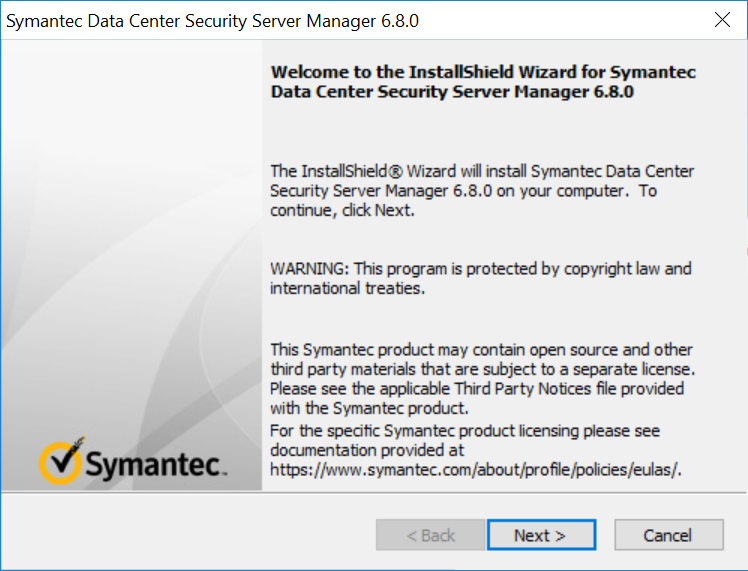
Check I accept the terms of the license agreement.
Click Next >.
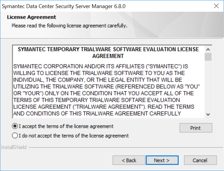
Verify installation location.
Click Next >.
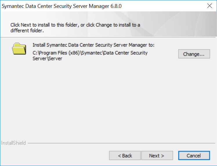
Review settings.
Click Install >.
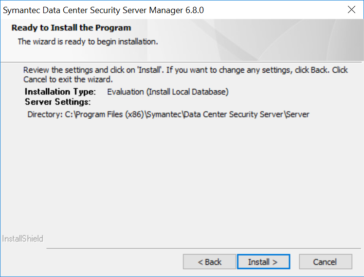
Wait for the setup and installation process to complete.
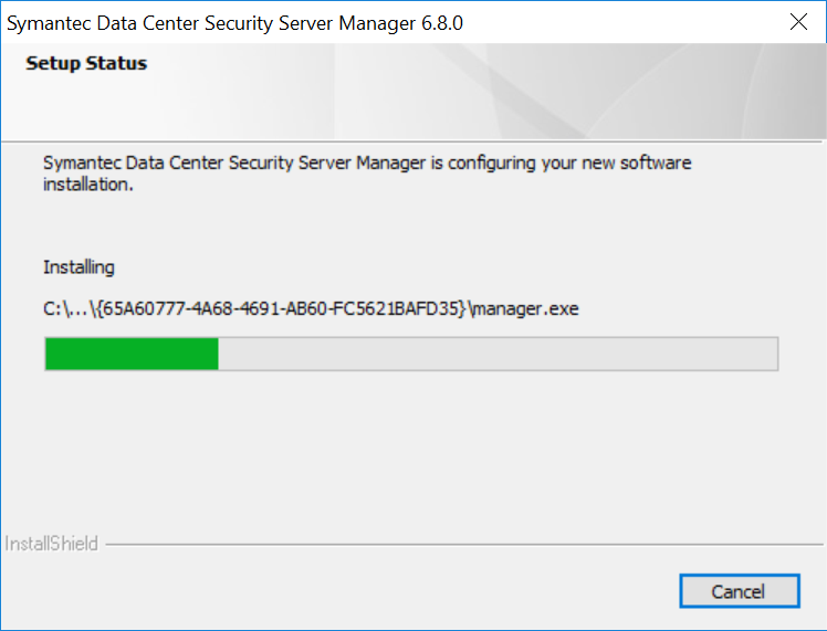
SQL Server will be installed automatically during the setup process.
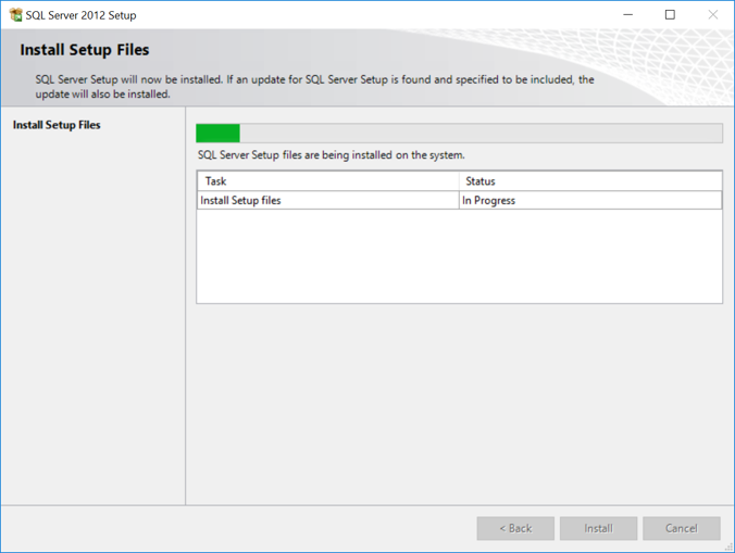
Provide the information below, and click Next:
Agent port: 443
Bridge port: 2443
Console port: 4443
Web server administration port: 8081
Web server shutdown port: 8006
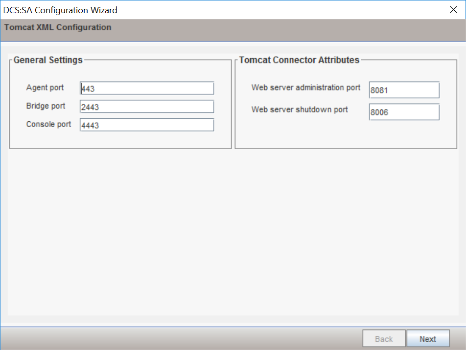
Uncheck Enable CWP Bridge and click Next.
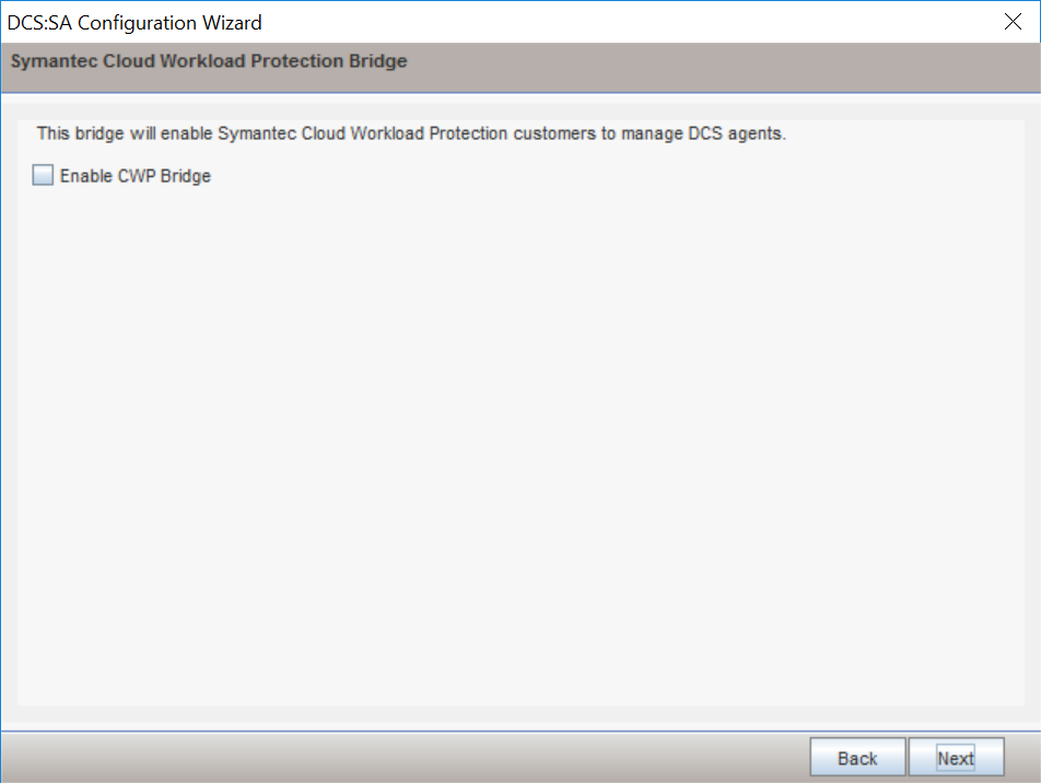
Verify settings for FQDN Hostname as WIN-RUQDO7KL8A7, Static IP Address as 192.168.120.207, and Java Heap Size as 6144, then click Next.
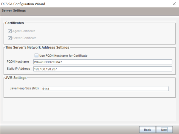
Create a password for the DB connection.
Click Next.
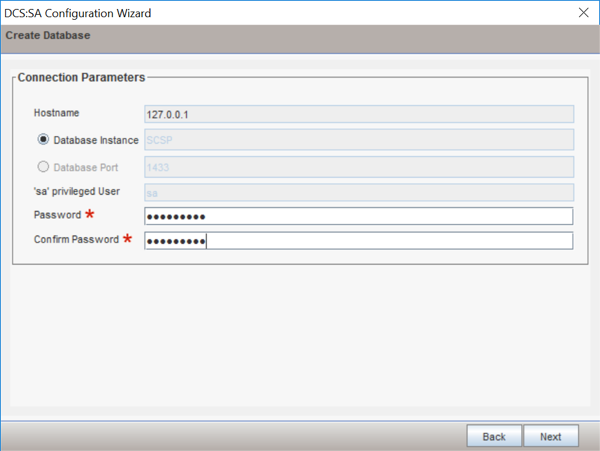
Verify Unified Management Console connection settings.
Create a password for the Unified Management Console connection.
Click Next.
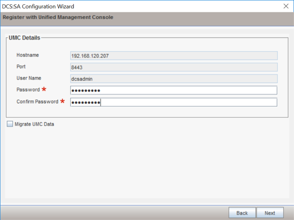
Verify the configuration settings and click Next.
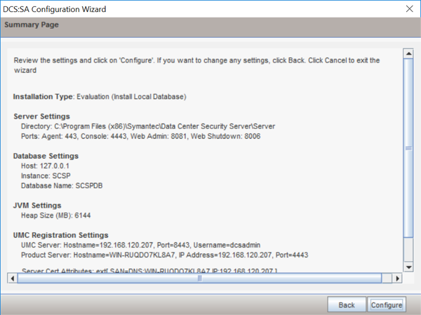
Wait for the configuration process to complete.
Click Finish.
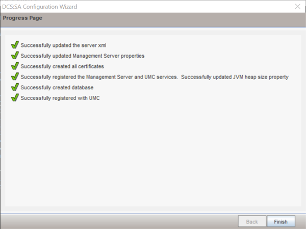
Wait for the installation to complete and click OK.
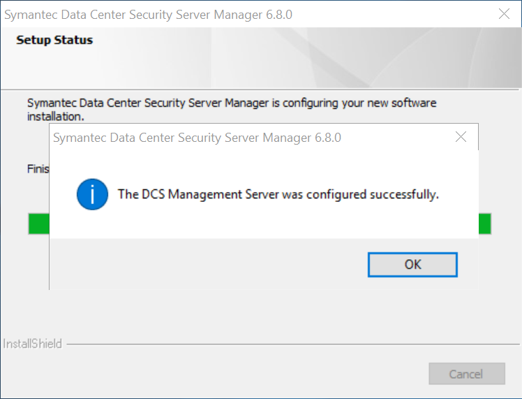
Symantec Datacenter Security Windows Agent Install
Run agent.exe.
Click Next >.
Check I accept the terms in the license agreement.
Click Next >.
Verify the installation and log files directories.
Click Next >.
Provide the information below, and click Next >:
Agent Name: WIN-RUQDO7KL8A
Polling Interval (sec): 300
Check Enable Intrusion Prevention.
Notification Port: 2222
Agent Protocol: HTTPS
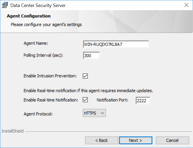
Provide the information below, and click Next:
Primary Management Server: 192.168.120.207
Agent Port: 443
Alternate Management Servers:
Management Server Certificate: C:\User\Administrator\Desktop\agent-cert.ssh
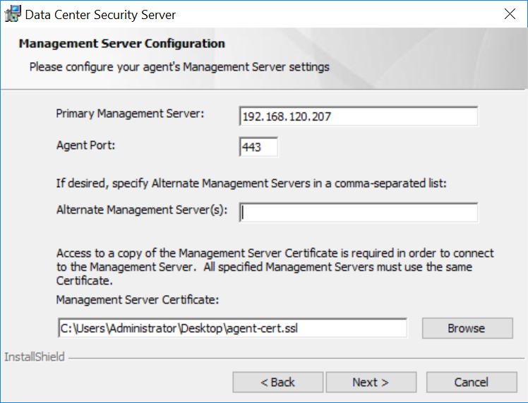
Specify a Server Security Group created through Symantec Datacenter Security Server or leave it blank to use the default security group.
Click Next >.
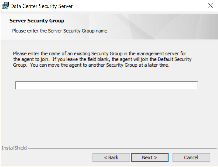
Verify installation and configuration settings and click Install.
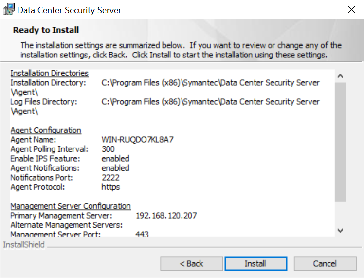
Wait for the installation process to complete.
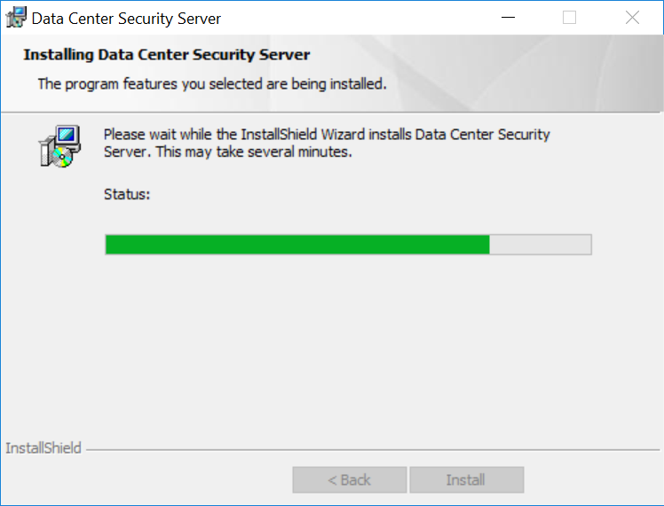
Click Finish.
Click Yes to restart the agent machine.
2.8.2 Symantec Endpoint Protection
Symantec Endpoint Protection is an agent-based security solution that provides anti-virus, intrusion prevention, application allow-listing, and other capabilities. For this project, Symantec SEP protects endpoints from malicious software and integrates with Symantec Endpoint Detection and Response to detect suspicious behavior.
System Requirements
CPUs: 4
Memory: 8GB RAM
Storage: 240 GB (thin provision)
Operating System: Microsoft Windows Server 2016
Network Adapter: VLAN 1901
Symantec Endpoint Protection Manager Installation
Launch Symantec_Endpoint_Protection_14.2.0.MP1_Part1_Trialware_EN.exe file.
Select the Install Symantec Protection Endpoint Manager option.
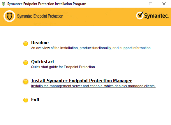
Proceed through the installation wizard by clicking Next >.
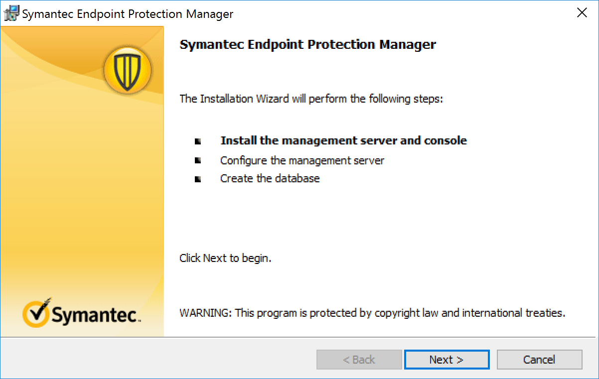
Check I accept the terms in the license agreement.
Click Next >.
Select the location you want to install Symantec Endpoint Protection Manager and click Next >. Keep the default location of C:\Program Files (x86)Symantec\Symantec Endpoint Protection Manager\.
Select Install.
After installation is complete, click Next > to continue with configuration of the management server.
Select Default configuration for new installation…; then click Next >.
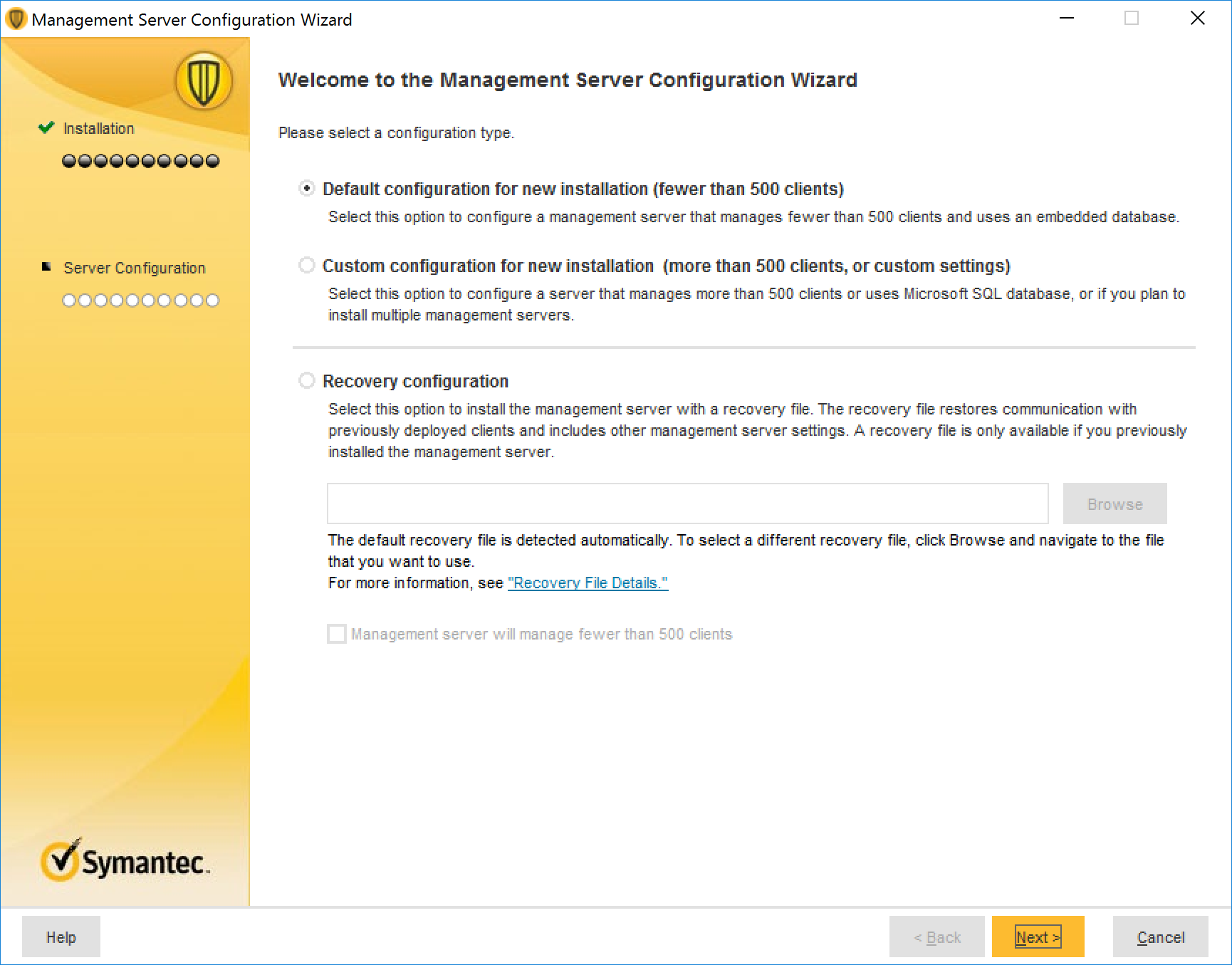
Provide the following information and click Next >.
Company Name: ********
User name: ********
Password: ********
Confirm password: ********
Email address: ********
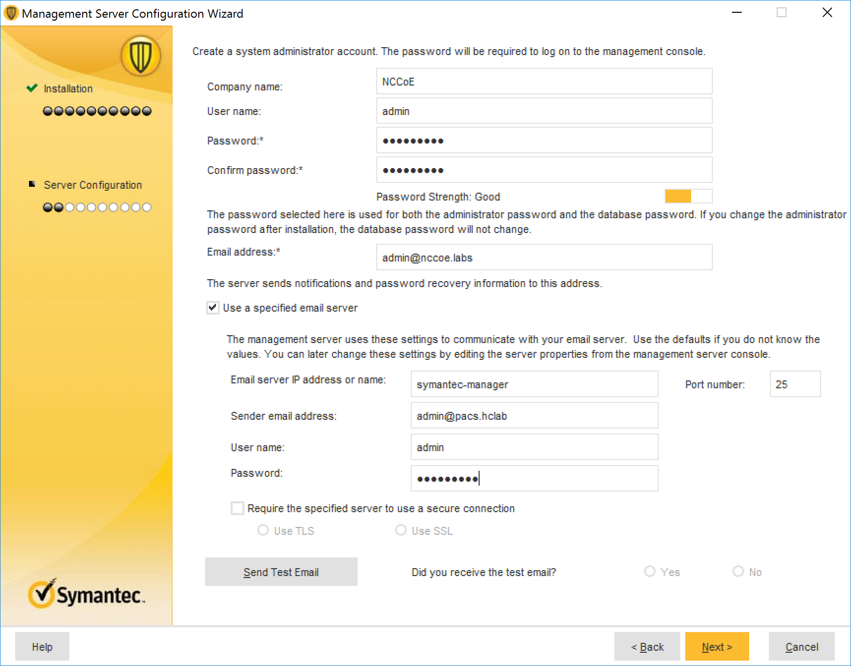
Confirm that Run LiveUpdate during installation is checked; click Next >.
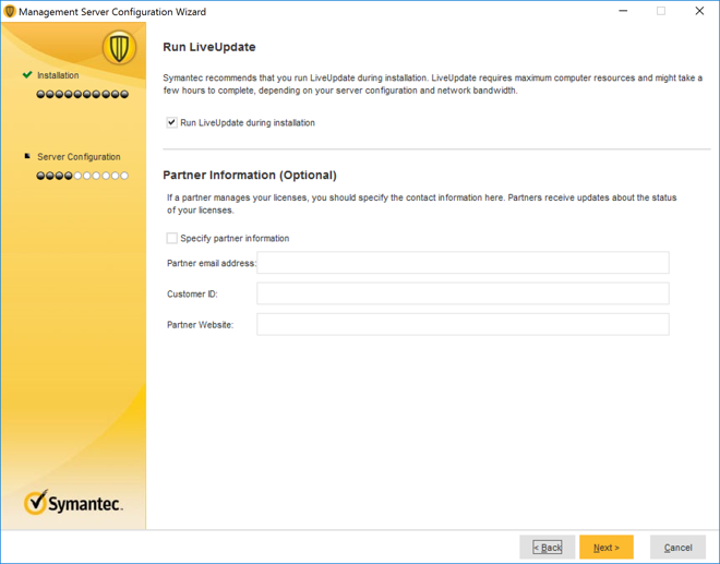
Uncheck Send anonymous data to Symantec to receive enhanced threat protection intelligence and click Next >.
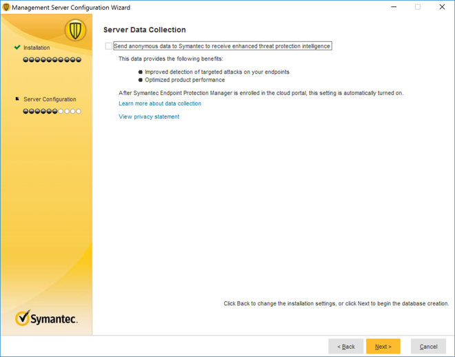
After installation is completed, check Launch the Symantec Endpoint Protection Manager to configure your hosts; click Finish.
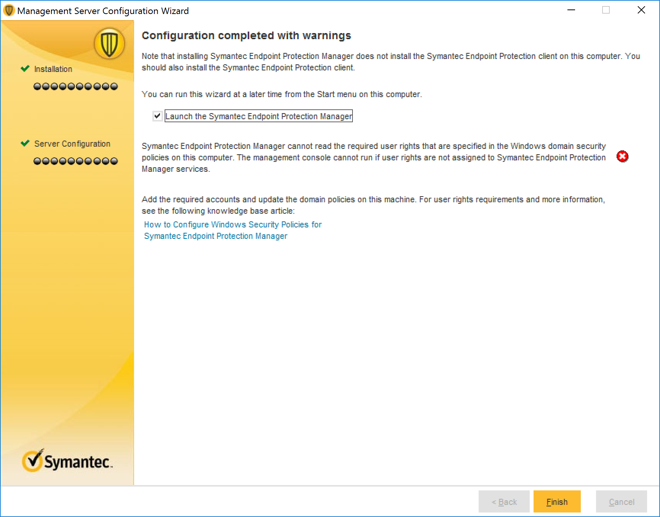
Symantec Endpoint Protection Host Windows Installation
Launch the Symantec Endpoint Protection Manager, and log in as the admin.
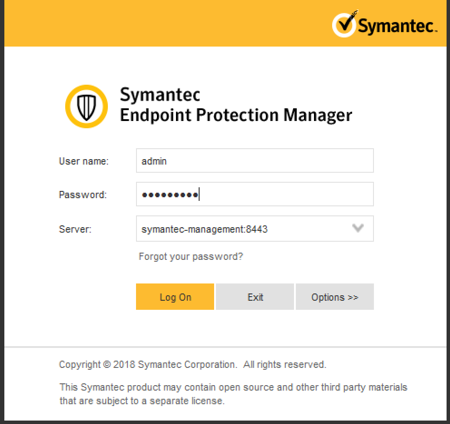
Select Install the client software on your computers from the Getting Started screen.
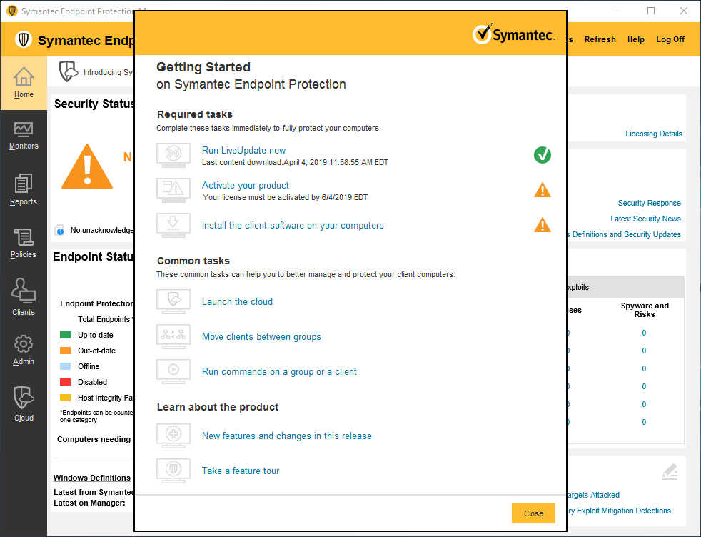
Confirm that New Package Deployment is checked and click Next >.
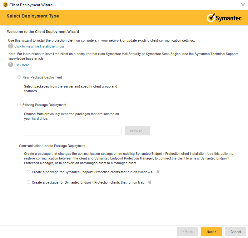
Confirm the settings for the Install Packages: Windows—Symantec Endpoint Protection version 14.2.1023.0100—English, Group: My Company, Install Feature Sets: Full Protection for Clients, Install Settings: Default Standard client installation settings for Windows. Click Next >.
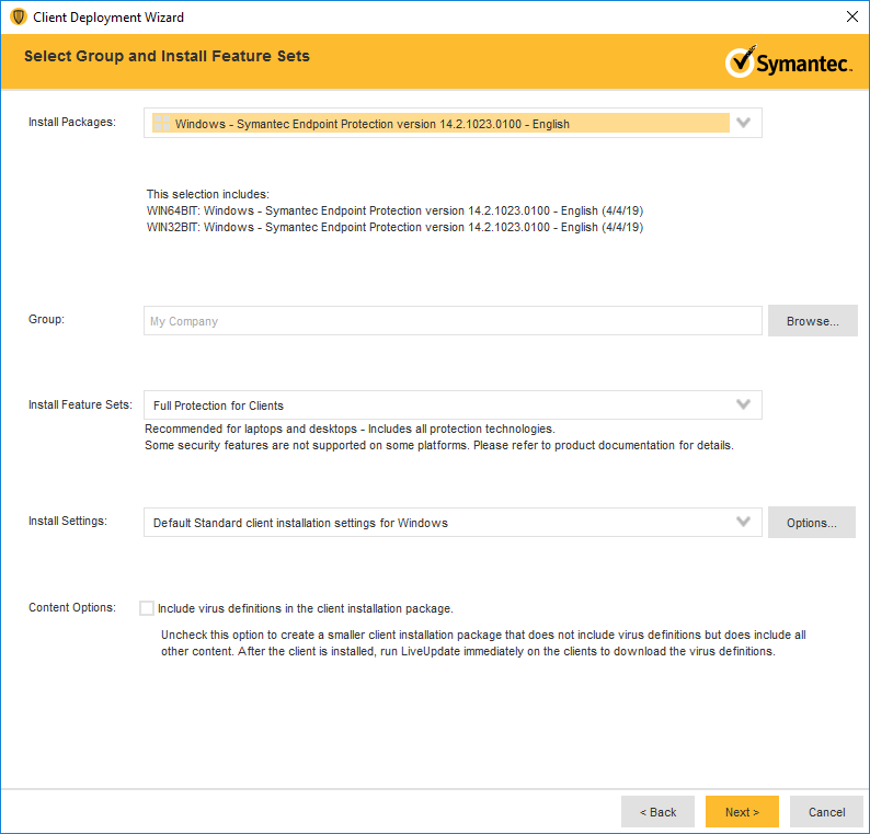
Confirm that Save Package is selected and click Next >.
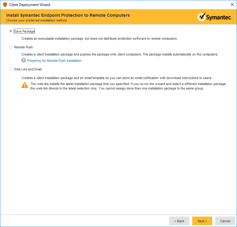
Specify the location to save the installation files and click Next >.
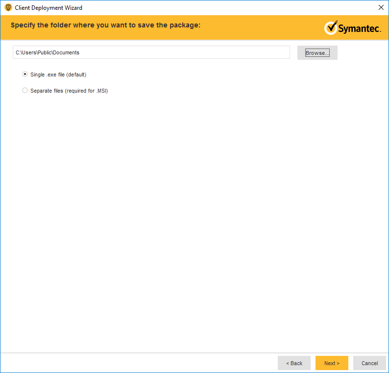
Confirm the details of the custom installation files and click Next >.
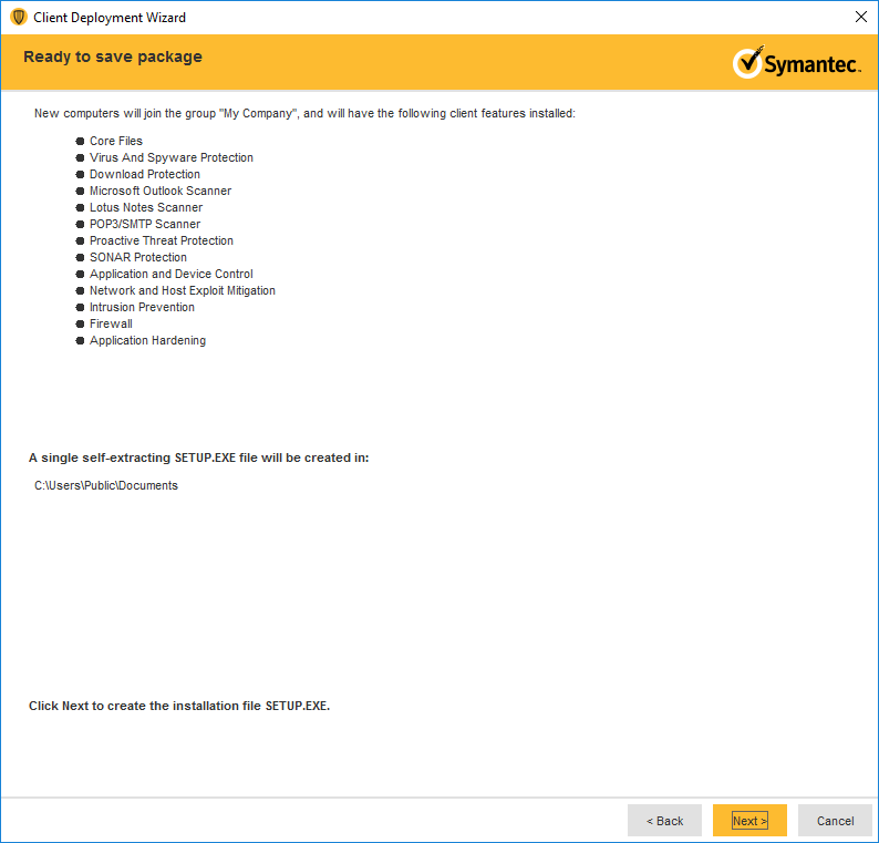
Move the installation package to the operating system where you want to install Symantec Endpoint Protection.
Launch the executable file and follow the prompts to install Symantec Endpoint Protection.
2.9 Data Security
A cloud storage solution, Microsoft Azure, was used to provide data security safeguards for medical images. The Azure solution provides data-at-rest encryption and, through a combination of access control and encryption, provides data security assurance.
The NCCoE lab used several different solutions to address data-in-transit encryption. As described in Section 2.6.2, DigiCert PKI, the lab implemented SSL/TLS encryption using DigiCert-issued certificates. Communications between modalities and clinical systems are secured using HIP, as described in Section 2.7.3, Tempered Networks Identity Defined Networking (IDN).
2.9.1 Microsoft Azure Cloud Storage
Microsoft Azure is a cloud service provider that provides storage and encryption for unstructured data in a remote location separate from the HDO environment. This project used an Azure blob storage account as a remote archive for medical images managed by the VNA. For more information on configuring Azure Storage accounts, including recommended security practices, visit Microsoft’s Azure Blob Storage Documentation [C13].
Microsoft Azure Blob Storage Creation
To proceed with the following steps, a Microsoft Storage account needs to be established.
From a web browser, navigate to https://portal.azure.com/.
Log in to the Microsoft account.
On the home screen, click Create a resource.
Type storage account into the search bar, then click Storage account.
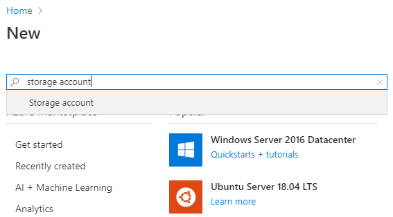
- On the Storage Account screen, click the Create button. A new screen will appear that requires information to be populated, found in the Basics tab.
When complete, click the Next: Networking button. Populate the Basics information using the following values:
On the Subscription field, select Enterprise from the pull-down menu.
Navigate to the Resource Group field. Select the corresponding resource group. If one is not available, create a new resource group.
Navigate to the Storage Account Name field. From the pull-down menu, select the storage account name that had previously been created.
Navigate to the Location field. From the pull-down menu, select (US) East US.
Navigate to the Performance field and select Standard.
Navigate to the Account Kind field. From the pull-down menu, select StorageV2.
Navigate to the Replication field. From the pull-down menu, select Geo-redundant storage (GRS).
Navigate to the Access Tier field and select Hot.
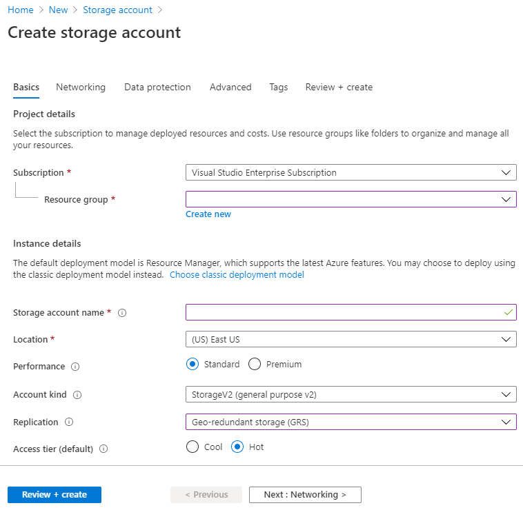
- Select the Networking tab. This will display a form with a series of fields that need to be populated. Fill out the Networking information using the
following respective values.
Navigate to the Connectivity Method field and select Public endpoint (all network).
Navigate to the Network Routing Preference field and select Microsoft network routing.
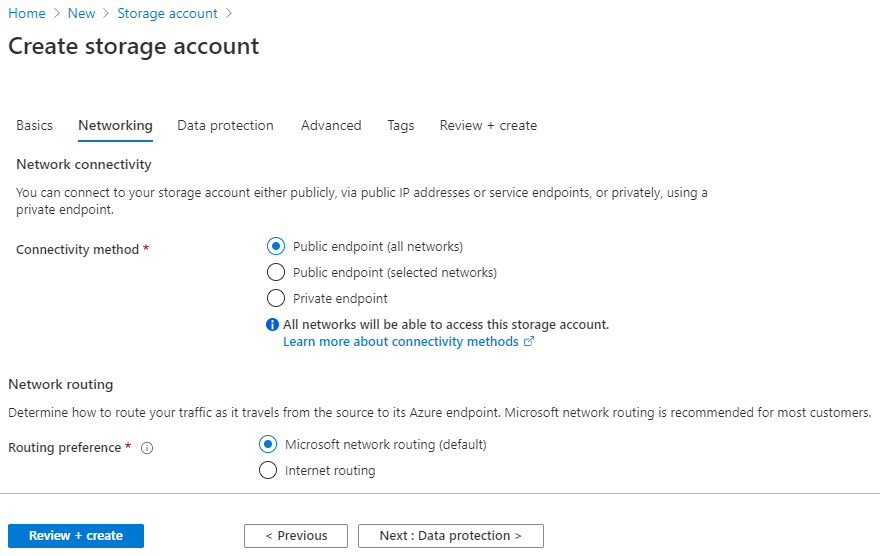
After supplying the values above, click the Next: Data Protection button.
Select the Data Protection tab, and populate the information as follows:
Navigate to the Blob Soft Delete field and select Enabled.
Navigate to the Blob Retainment Period in Days field and enter 60.
Navigate to the File Share Soft Delete field and select Disabled.
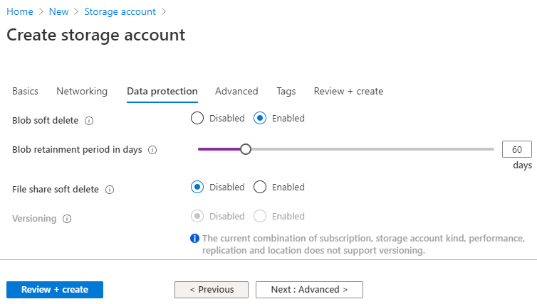
Click the Next: Advanced button.
Populate the Advanced information as follows:
Navigate to the Secure Transfer Required: field and select Enabled.
Navigate to the Blob Public Access field and select Disabled.
Navigate to the Minimum TLS Version pull-down menu and select Version 1.2.
Click Next: Tags button.
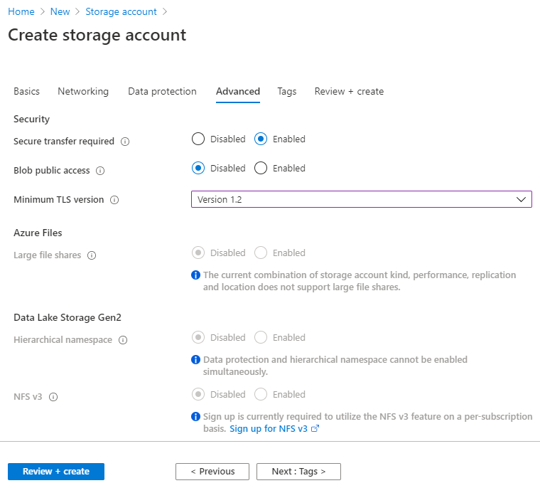
Fill out the Tags information, then click Next: Review + create.
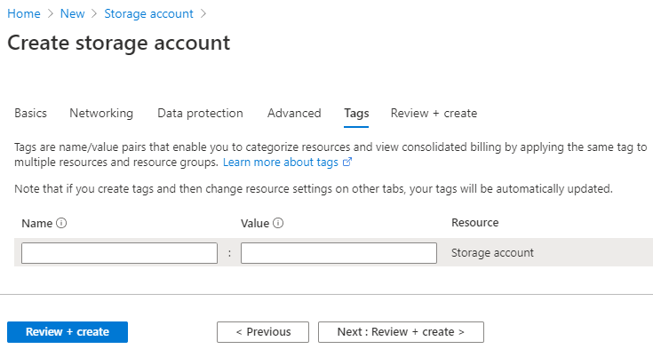
Review the Create storage account configuration page, verify the configuration information, then click Create.
Basics
Subscription: Visual Studio Enterprise Subscription
Resource group: ********
Location: East US
Storage account name: ********
Deployment model: Resource manager
Account kind: StorageV2 (general purpose v2)
Replication: Geo-redundant storage (GRS)
Performance: Standard
Access tier (default): Hot
Networking
Connectivity method: Public endpoint (all networks)
Default routing tier: Microsoft network routing (default)
Data protection
Blob soft delete: Enabled
Blob Retainment Period in Days: 60
File share soft delete: Disabled
Blob change feed: Disabled
Versioning: Disabled
Advanced
Secure transfer required: Enabled
Blob public access: Disabled
Minimum TLS version: TLS 1.2
Large File Shares: Disabled
Hierarchical namespace: Disabled
NSF v3: Disabled
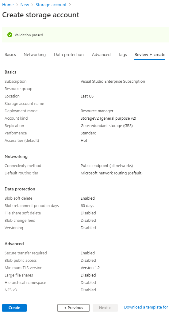
Wait for the deployment process to finish. When the deployment is ready, a screen will announce that the deployment has been created.
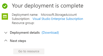
Navigate to the home screen and click All resources.

Click the newly created storage account.
Navigate to Firewalls and virtual networks on the left.
Make the following modifications, then click Save:
Allow access from: Selected networks
Address range: ********

Navigate to Encryption on the left.
Under Encryption type, select Customer-managed keys.
Under Encryption key, select Select from key vault.
Under Key vault and key, click Select a key vault and key.
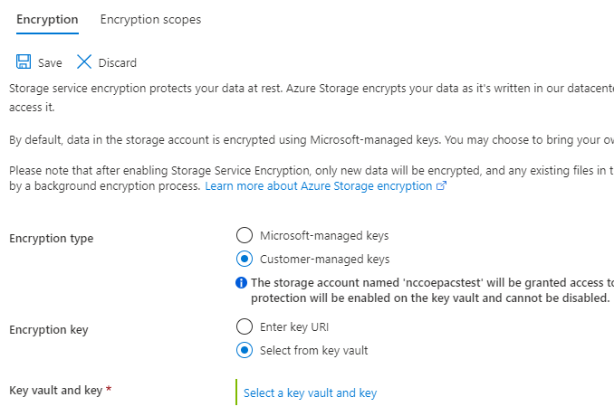
Under Key Vault, click Create New.
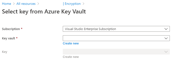
On the Create key vault screen, select the Basics tab, and populate the information as follows:
Navigate to the Resource Group field, select the corresponding resource group.
Navigate to the Key Vault Name field, select the corresponding key vault name.
Navigate to the Pricing Tier field; select Premium.
Navigate to the Soft-Delete field; select Enabled.
Navigate to the Days to Retain Deleted Vaults field; enter 60.
Navigate to the Purge Protection field; select Allow purging.
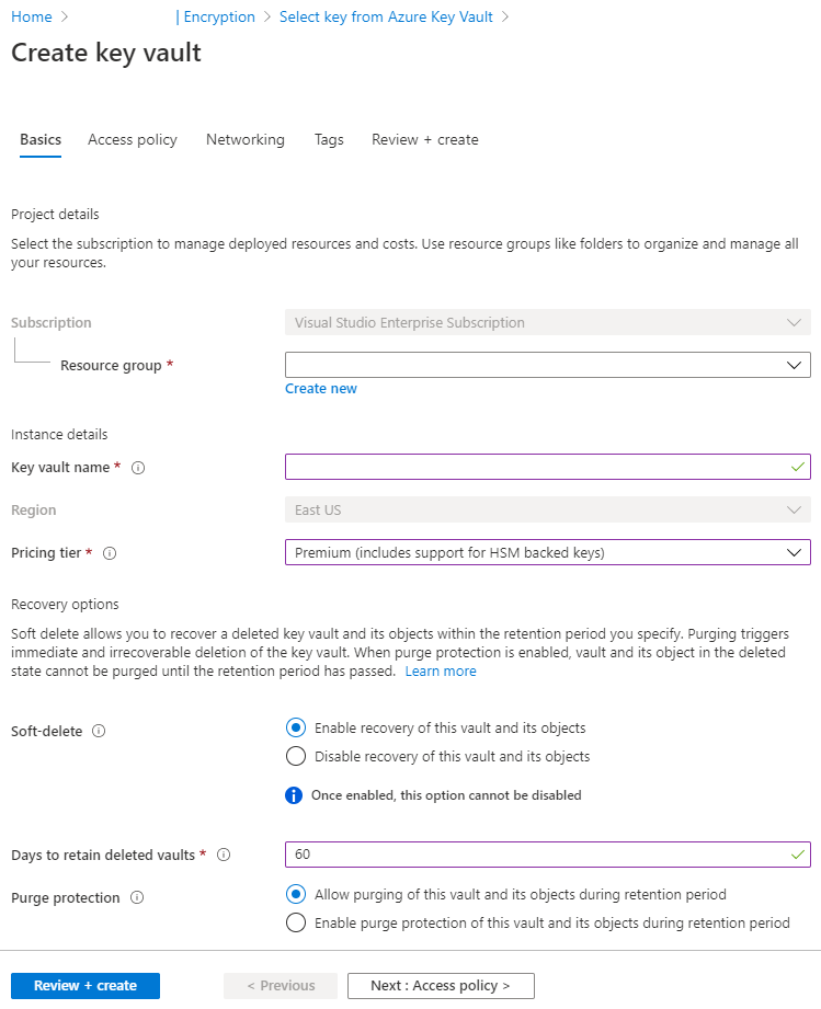
Click the Next: Access Policy button.
Fill out the Access Policy information, then click Next: Networking.
Navigate to the Enable Access to group, and set the following checkboxes:
Azure Virtual Machines for deployment: Unchecked
Azure Resource Manager for template deployment: Unchecked
Azure Disk Encryption for volume encryption: Unchecked
Navigate to the Current Access Policies: group and keep the Default User Permissions.
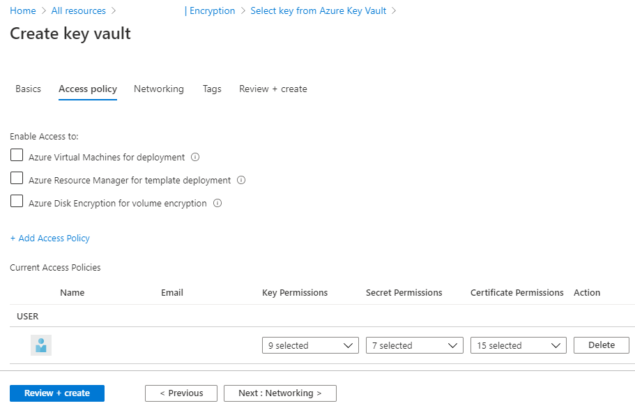
On the Create key vault screen, under the Networking tab, navigate to the line labelled Connectivity method and select Public endpoint(all networks) and then click on Next:Tags>.
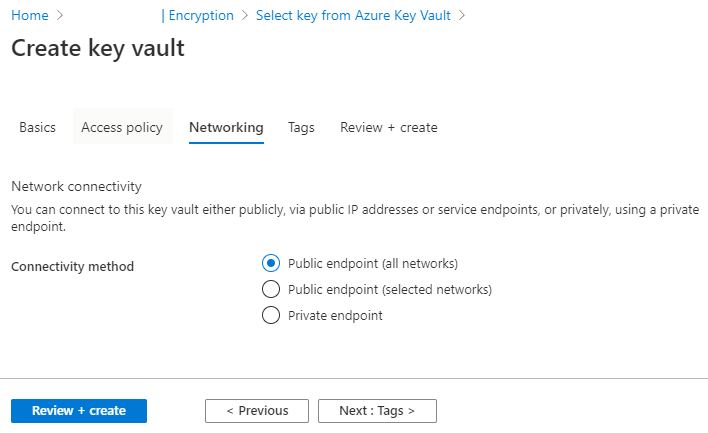
Fill out the Tags information, then click Next: Review + create.
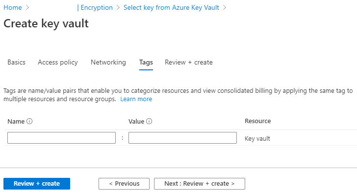
Review the Create key value configuration page, verify the configuration information, then click Create.
Basics
Subscription: Visual Studio Enterprise Subscription
Resource group: ********
Key vault name: ********
Region: East US
Pricing tier: Premium
Soft-Delete: Enabled
Purge Protection During Retention Period: Disabled
Retention period (days): 60 days
Access policy
Azure Virtual Machines for deployment: Disabled
Azure Resource Manager for template deployment: Disabled
Azure Disk Encryption for volume encryption: Disabled
Permission model: Access control list
Access policies: 1
Networking
Connectivity method: Public endpoint (all networks)
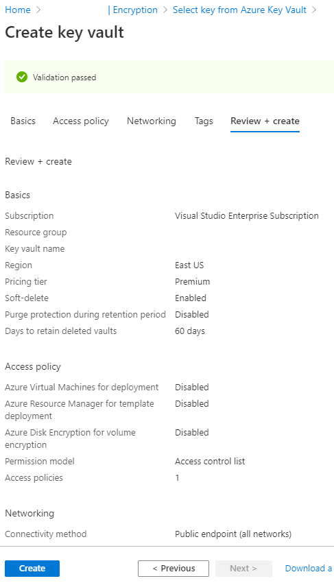
Wait for the creation process to finish.
Navigate to the Key field and click Create New.
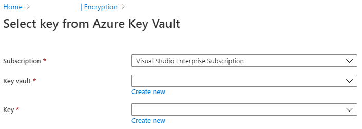
Fill out the form with the following information, then click Create:
Options: Generate
Name: ********
Key Type: RSA
RSA Key Size: 2048
Enabled?: Yes
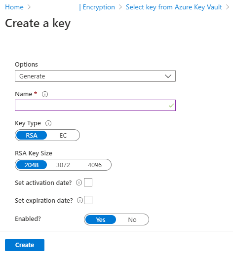
Once the key has been successfully created, ensure the values for Subscription, Key Vault, and Key are correct as follows, then click Select:
Subscription: Visual Studio Enterprise Subscription
Key vault: ********
Key: ********
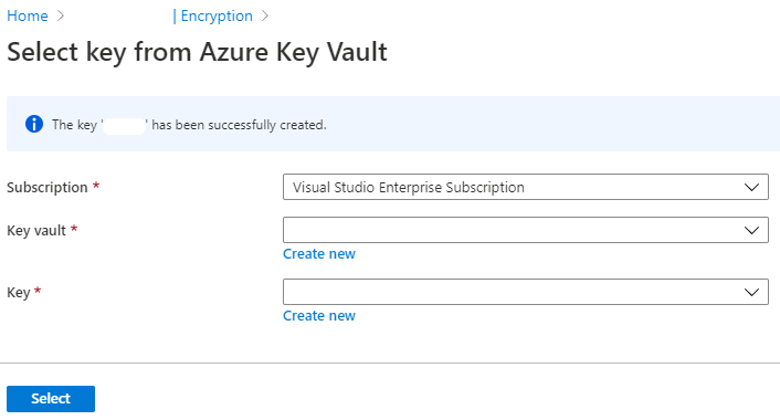
Verify the following Encryption information, then click Save:
Encryption type: Customer-managed keys
Encryption key: Select from key vault
Key vault: ********
Key: ********
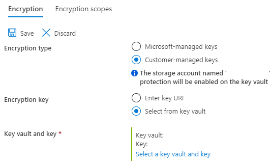
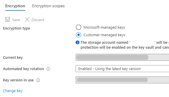
Take note of the key strings. These will be used to authenticate the VNA’s requests to the storage account:
Storage account name: ********
Key: ********
Connection string: ********
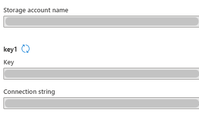
Navigate to Storage Explorer on the left of the Storage Explorer (preview) page.
Right-click BLOB CONTAINERS, then click Create blob container.
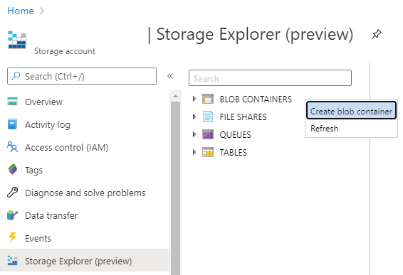
Fill out value of the Name field for the New container, then click Create.
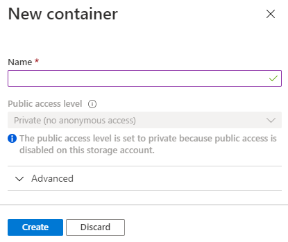
The established storage account is ready for use, and the VNA can be configured to send and receive medical images to and from the storage account container.
2.9.2 Hyland VNA Cloud Archive Device
For this project, a Hyland engineer upgraded the Hyland Acuo VNA v6.0.4 and NilRead Enterprise v4.3.31.98805 to Acuo VNA v6.0.4.2798_H2_P2 and NilRead Enterprise v4.4.32.103830. These upgrades enabled the Hyland VNA to store patient studies in a Microsoft Azure storage account. When configuring the connection to the Azure account, the VNA allowed an engineer to determine the number of days that patient studies were held in the cache. For testing purposes, this project kept studies in the VNA cache for three days and immediately stored these studies in the Azure storage. When configuring for production, identify time frames for cache and cloud storage that coincide with an HDO’s business practices.
Hyland NilRead Archive Device Configuration
Open a web browser and navigate to the Acuo Admin Portal created in Section 2.2.2, Hyland Acuo VNA.
Enter the Username and Password for the Admin Portal, and click Sign In.
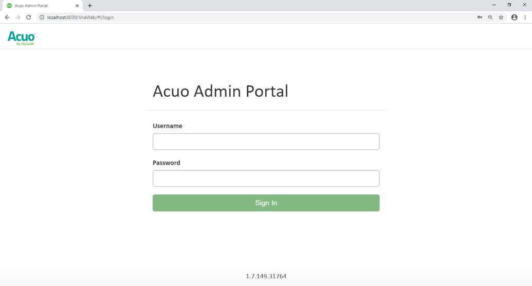
Navigate to the Archive Devices section of the portal by clicking the drop-down list on the top left corner of the screen and selecting Storage Management and then Archive Devices.
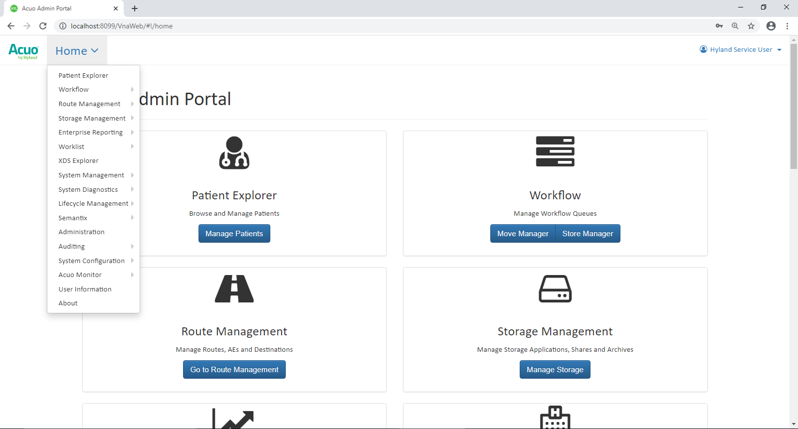
Click Add New Archive Device in the top of the screen, then select Azure.
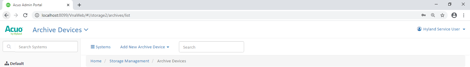
In the Add New Azure Archive Device window, provide the following Azure account information:
Name: ********
Container Size: 20 MB
Account Name: ********
Account Key: ******************
Click Add Archive Device.
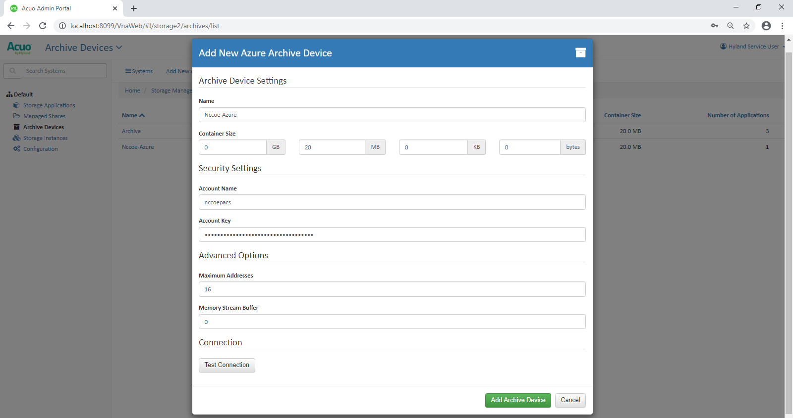
Connect Microsoft Azure Archive Device to the RADIOLOGY Storage Application
Click Storage Applications on the left-hand side of the screen.
Click RADIOLOGY.
Scroll down and click Add Archive.
Device: ********
Write files older than: 1 day(s)
Enable Write files to archive.
Click Add Archive.
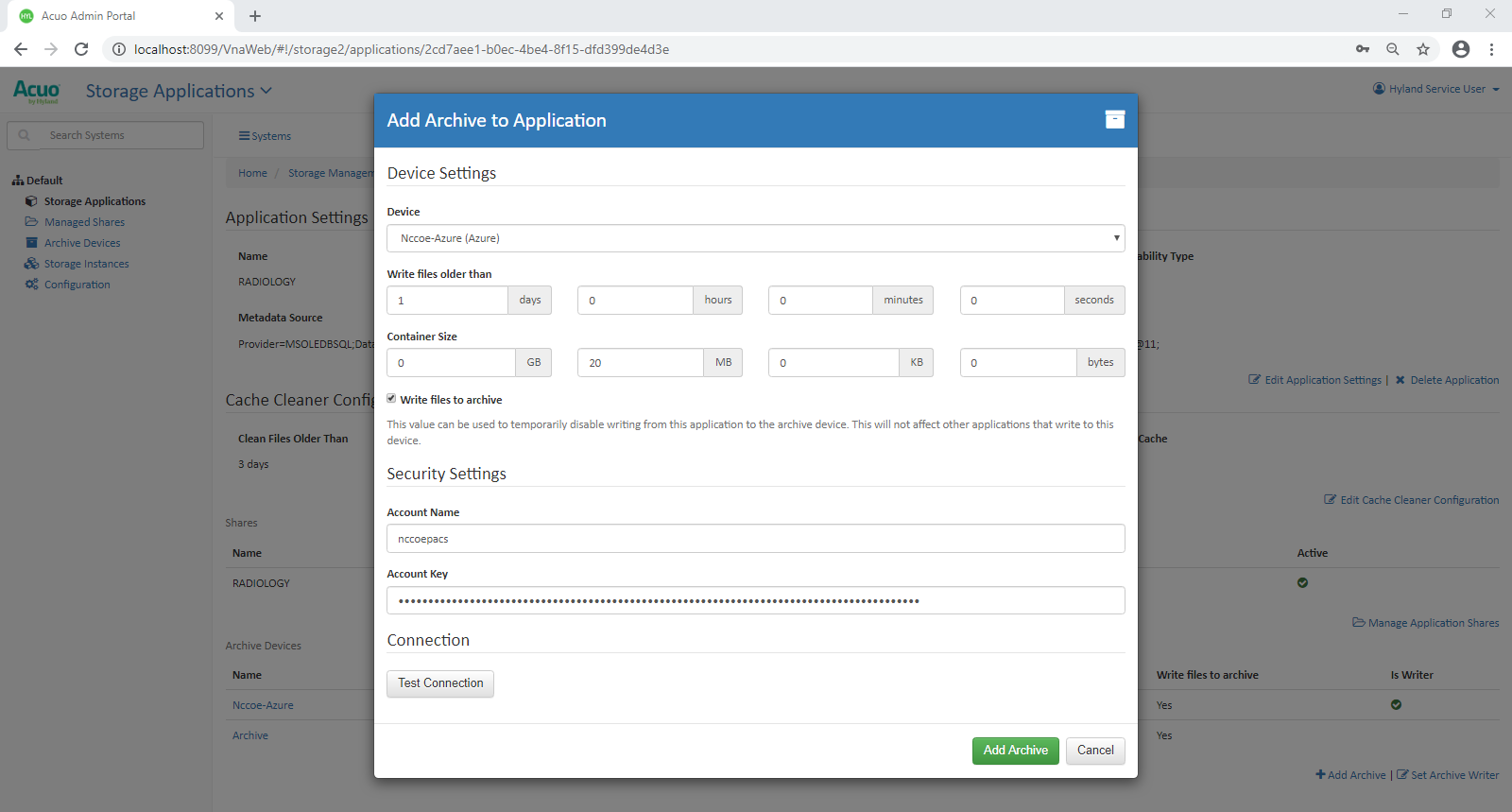
Set Parameters for Image Archival to Microsoft Azure
Select Nccoe-Azure under Archive Devices at the bottom of the screen.
Set Write files older than to 0 days.
Click Save Changes.
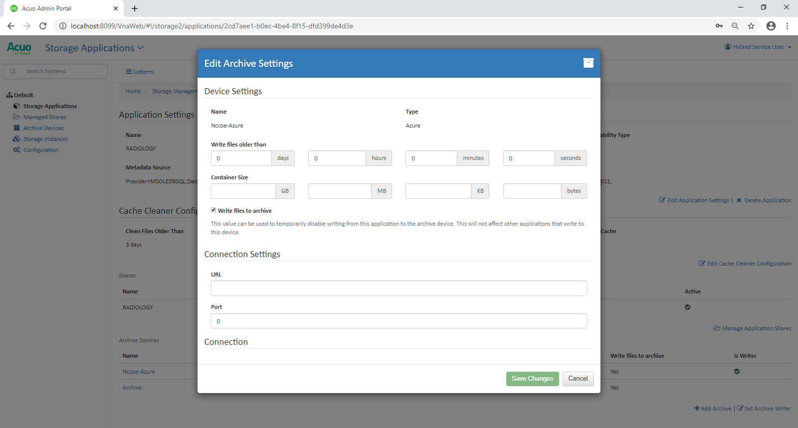
Set Parameters for Storing Images in the VNA’s Cache
Click Edit Cache Cleaner Configuration.
Set Clean Files Older Than to 3 days.
Click Save Changes.
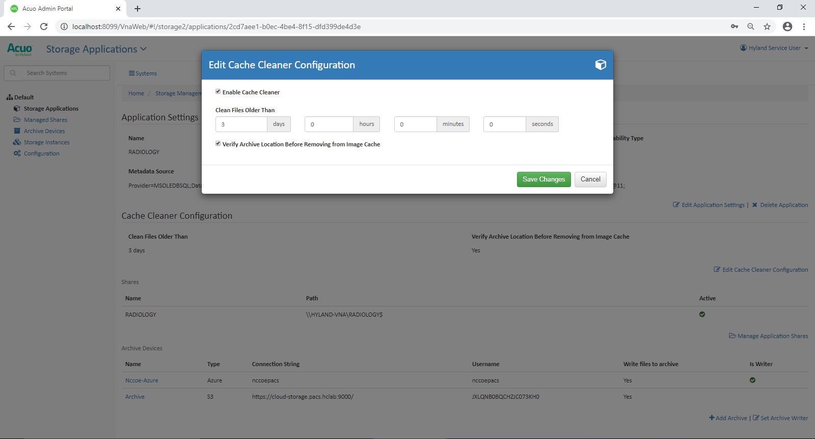
2.10 Secure Remote Access
Both healthcare and IT systems require access by vendor support technicians for remote configuration, maintenance, patching, and updates to software and firmware. This project implemented secure remote access by integrating Symantec Validation and ID Protection (VIP) into the ConsoleWorks authentication mechanism. This implementation enforced two-factor authentication with username, password, and a onetime passcode.
2.10.1 TDi Technologies ConsoleWorks
The NCCoE lab implemented a VendorNet using TDi ConsoleWorks, which is a browser interface that enables HDOs to manage, monitor, and record activities from external vendors in the IT infrastructure.
System Requirements
CPUs: 1
Memory: 8 GB RAM
Storage: 40 GB
Operating System: CentOS 7
Network Adapter: VLAN 1097
TDi ConsoleWorks Installation
The TDi ConsoleWorks installation in this PACS environment replicates the installation in the Wireless Infusion Pumps Project. For detailed installation guidance, please refer to Section 2.1.8, TDi ConsoleWorks External Remote Access, in NIST SP 1800-8C, Securing Wireless Infusion Pumps [C12].
TDi ConsoleWorks Radius Authentication Configuration
In our project, we integrated TDi ConsoleWorks with the Symantec VIP for two-factor authentication. This section explains how to enable external authentications for ConsoleWorks. In the next section, we explain how we configured Symantec VIP to integrate with ConsoleWorks.
Download extern_auth_radius.so file from ConsoleWorks support site [C14].
Move extern_auth_radius.so file to /opt/ConsoleWorks/bin directory.
Restart ConsoleWorks by executing cw_stop and cw_start scripts located in the /opt/ConsoleWorks/bin directory.
From the ConsoleWorks web interface, navigate to Security, and click External Authentication.
Click add to create a new external authentication source.
Fill out the required fields. The setup we used is below:
Record Name: Radius
Ensure Enable is checked.
For Library, select radius.
Parameter 1: 192.168.120.190:1812/*******
Parameter 2: 30
Parameter 6: 15
Template User: CONSOLE_MANAGER
Continue through the prompt by clicking Next; click Save on the final prompt.
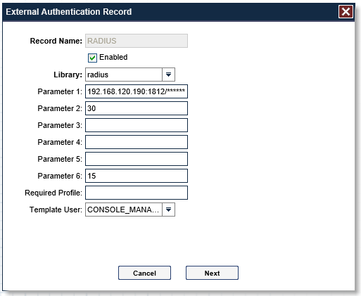
Ensure that Enable External Authentication is checked.
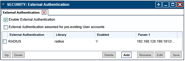
2.10.2 Symantec Validation and ID Protection (VIP)
Symantec Validation and ID Protection is an authentication service that provides various forms of authentication such as push, short message service (SMS), and biometric. This project used Symantec VIP as a second form of authentication for remote access to the PACS architecture through TDi Technologies ConsoleWorks.
System Requirements
CPUs: 4
Memory: 8192 MB RAM
Storage: 240 GB (thin provision)
Operating System: Microsoft Windows Server 2016
Network Adapter: VLAN 1201
Symantec VIP Installation
Right-click on setup.exe file for VIP Enterprise Gateway 9.8.0; select Run as administrator.
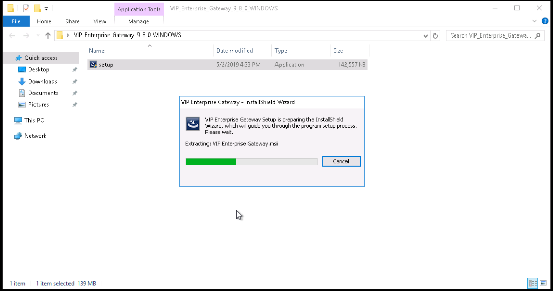
Proceed through the installation wizard by clicking Next >.
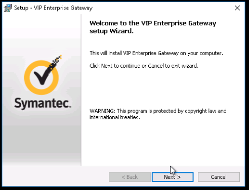
Check I accept the agreement.
Click Next >.
Create a username as admin and a password and click Next >.
Keep the default installation location by clicking Next >.
Click Install.
Click Finish after installer is complete.
On the Symantec VIP local machine, open a web browser, and navigate to http://localhost:8232. Sign in with the User Name as admin and corresponding Password specified during installation.
Select User Store from the menu bar.
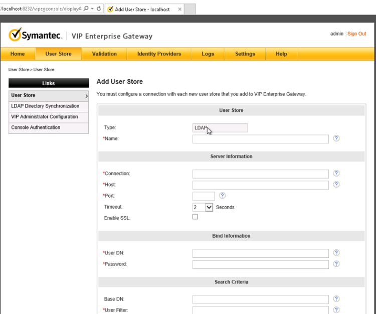
Add a user store with the following information:
Name: AD PACS
Connection: ad-main
Host: ad.pacs.hclab
Port: 389
User DN: CN=symantec, DC=pacs, DC=hclab
Password: *********
Base DN: DC=pacs, DC=hclab
User Filter: (&(&objectClass=user)(objectCategory=person))(sAMAcountName=%s))
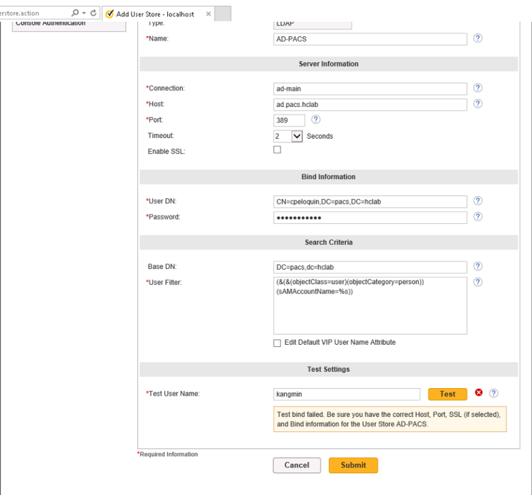
Log into VIP Manager by navigating to https://manager.vip.symantec.com/vipmgr. Use the account provided by Symantec.
Select Register Your VIP Credential. Provide the Credential ID and Security Code of your credentials. Credentials can be downloaded by navigating to https://vip.symantec.com/.
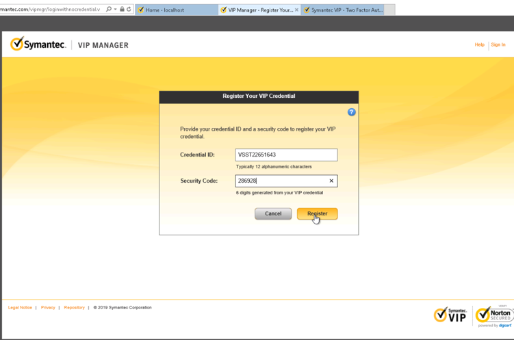
After registering the credential, select Go to My Account.
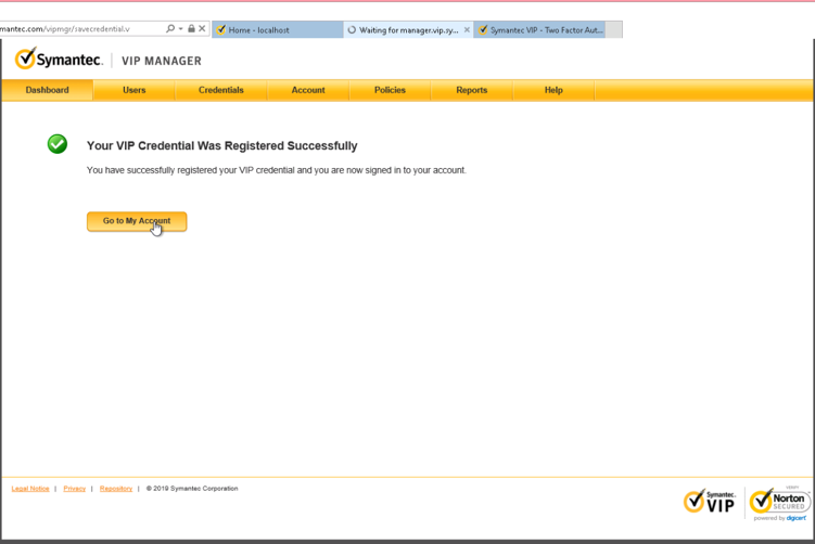
Select Account from menu bar, then select Manage VIP Credentials.
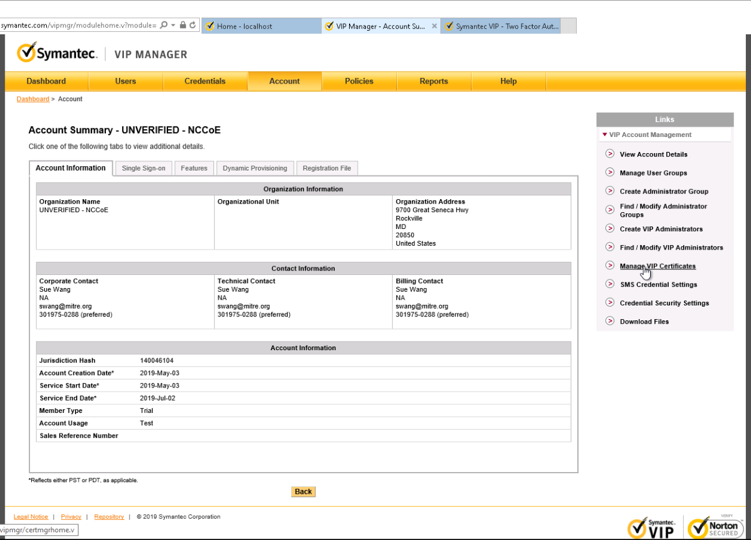
Select Request a Certificate.
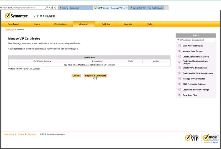
Provide a Certificate Name as NCCoE_VIP_Cert. Click Submit Request.
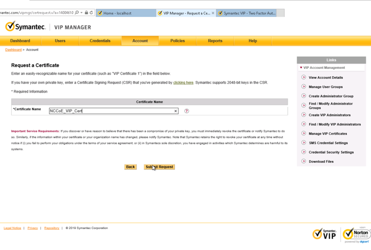
Select PKCS#12 format and create a password for the requested certificate. Then select Download Certificate.
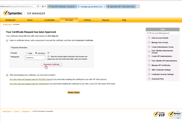
Save the certificate on the Symantec VIP local machine.
Navigate to http://localhost:8232. After logging, select Add VIP Certificate.
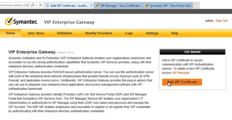
Select Browse and upload the certificate from the previous step. Enter the correct password and alias for the certificate, then click Submit.
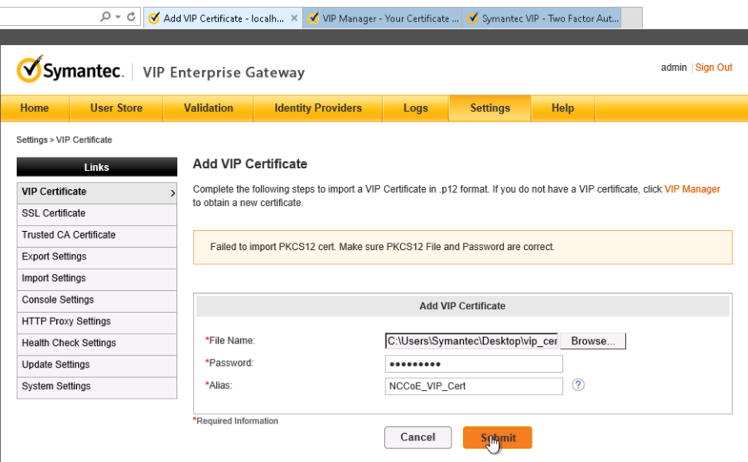
Select Validation from the menu bar, select Custom configuration, and provide the information that follows:
Server Name: vip
Local IP: 192.168.120.190
Port: 1812
RADIUS Shared Secret: *****
Confirm RADIUS Shared Secret: *****
Enable First Factor: Checked
Authentication on: Enterprise
Authentication Sequence: LDAP Password–VIP Authentication
User Store: AD PACS
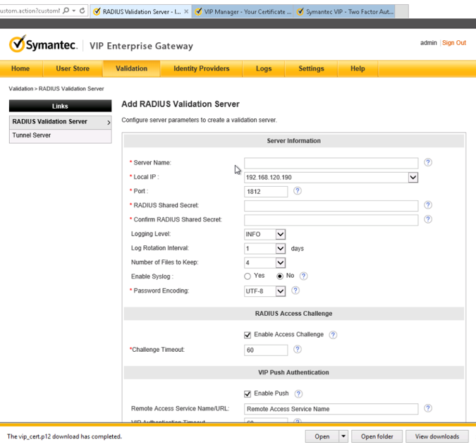
Click Submit.
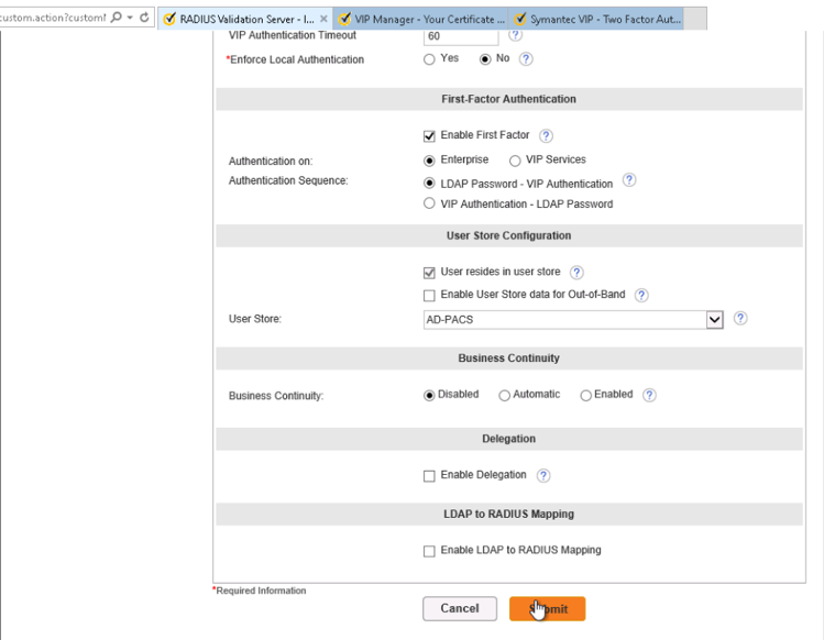
Ensure that VIP Server Status is set to ON.