NIST SPECIAL PUBLICATION 1800-24B
Securing Picture Archiving and Communication System (PACS):
Cybersecurity for the Healthcare Sector
Volume B:
Approach, Architecture, and Security Characteristics
Jennifer Cawthra
National Cybersecurity Center of Excellence
National Institute of Standards and Technology
Bronwyn Hodges
Jason Kuruvilla*
Kevin Littlefield
Bob Niemeyer
Chris Peloquin
Sue Wang
Ryan Williams
Kangmin Zheng
The MITRE Corporation
McLean, Virginia
*Former employee; all work for this publication done while at employer.
December 2020
FINAL
This publication is available free of charge from: https://doi.org/10.6028/NIST.SP.1800-24
The first draft of this publication is available free of charge from: https://www.nccoe.nist.gov/library/securing-picture-archiving-and-communication-system-nist-sp-1800-24-practice-guide

DISCLAIMER
Certain commercial entities, equipment, products, or materials may be identified by name of company logo or other insignia in order to acknowledge their participation in this collaboration or to describe an experimental procedure or concept adequately. Such identification is not intended to imply special status or relationship with NIST or recommendation or endorsement by NIST or NCCoE; neither is it intended to imply that the entities, equipment, products, or materials are necessarily the best available for the purpose.
National Institute of Standards and Technology Special Publication 1800-24B, Natl. Inst. Stand. Technol. Spec. Publ. 1800-24B, 102 pages, (December 2020), CODEN: NSPUE2
FEEDBACK
As a private-public partnership, we are always seeking feedback on our practice guides. We are particularly interested in seeing how businesses apply NCCoE reference designs in the real world. If you have implemented the reference design, or have questions about applying it in your environment, please email us at hit_nccoe@nist.gov.
All comments are subject to release under the Freedom of Information Act.
NATIONAL CYBERSECURITY CENTER OF EXCELLENCE
The National Cybersecurity Center of Excellence (NCCoE), a part of the National Institute of Standards and Technology (NIST), is a collaborative hub where industry organizations, government agencies, and academic institutions work together to address businesses’ most pressing cybersecurity issues. This public-private partnership enables the creation of practical cybersecurity solutions for specific industries, as well as for broad, cross-sector technology challenges. Through consortia under Cooperative Research and Development Agreements (CRADAs), including technology partners—from Fortune 50 market leaders to smaller companies specializing in information technology security—the NCCoE applies standards and best practices to develop modular, adaptable example cybersecurity solutions using commercially available technology. The NCCoE documents these example solutions in the NIST Special Publication 1800 series, which maps capabilities to the NIST Cybersecurity Framework and details the steps needed for another entity to re-create the example solution. The NCCoE was established in 2012 by NIST in partnership with the State of Maryland and Montgomery County, Maryland.
NIST CYBERSECURITY PRACTICE GUIDES
NIST Cybersecurity Practice Guides (Special Publication 1800 series) target specific cybersecurity challenges in the public and private sectors. They are practical, user-friendly guides that facilitate the adoption of standards-based approaches to cybersecurity. They show members of the information security community how to implement example solutions that help them align with relevant standards and best practices, and provide users with the materials lists, configuration files, and other information they need to implement a similar approach.
The documents in this series describe example implementations of cybersecurity practices that businesses and other organizations may voluntarily adopt. These documents do not describe regulations or mandatory practices, nor do they carry statutory authority.
ABSTRACT
Medical imaging plays an important role in diagnosing and treating patients. The system that manages medical images is known as the picture archiving communication system (PACS) and is nearly ubiquitous in healthcare environments. PACS is defined by the Food and Drug Administration (FDA) as a Class II device that “provides one or more capabilities relating to the acceptance, transfer, display, storage, and digital processing of medical images.” PACS centralizes functions surrounding medical imaging workflows and serves as an authoritative repository of medical image information.
PACS fits within a highly complex healthcare delivery organization (HDO) environment that involves interfacing with a range of interconnected systems. PACS may connect with clinical information systems and medical devices and engage with HDO-internal and affiliated health professionals. Complexity may introduce or expose opportunities that allow malicious actors to compromise the confidentiality, integrity, and availability of a PACS ecosystem.
The NCCoE at NIST analyzed risk factors regarding a PACS ecosystem by using a risk assessment based on the NIST Risk Management Framework. The NCCoE also leveraged the NIST Cybersecurity Framework and other relevant standards to identify measures to safeguard the ecosystem. The NCCoE developed an example implementation that demonstrates how HDOs can use standards-based, commercially available cybersecurity technologies to better protect a PACS ecosystem. This practice guide helps HDOs implement current cybersecurity standards and best practices to reduce their cybersecurity risk and protect patient privacy while maintaining the performance and usability of PACS.
KEYWORDS
access control; auditing; authentication; authorization; behavioral analytics; cloud storage; DICOM; EHR; electronic health records; encryption; microsegmentation; multifactor authentication; PACS; PAM; picture archiving and communication system; privileged account management; vendor neutral archive; VNA
ACKNOWLEDGMENTS
We are grateful to the following individuals for their generous contributions of expertise and time.
Name |
Organization |
|---|---|
Matthew Hyatt |
Cisco |
Kevin McFadden |
Cisco |
Cletis McLean |
Cisco |
Peter Romness |
Cisco |
Deidre Cruit |
Clearwater Compliance |
Mike Nelson |
DigiCert |
Taylor Williams |
DigiCert |
Andy Gray |
Forescout |
Katherine Gronberg |
Forescout |
William Canter |
Hyland |
Kevin Dietz |
Hyland |
Joseph Davis |
Microsoft |
Janet Jones |
Microsoft |
Dan Menicucci |
Microsoft |
Mehwish Akram |
The MITRE Corporation |
Steve Edson |
The MITRE Corporation |
Sallie Edwards |
The MITRE Corporation |
Donald Faatz |
The MITRE Corporation |
Harry Perper |
The MITRE Corporation |
David Alfonso |
Philips Healthcare |
Jonathan Bagnall |
Philips Healthcare |
Julian Castro |
Philips Healthcare |
Sukanta Das |
Philips Healthcare |
Jason Dupuis |
Philips Healthcare |
Michael McNeil |
Philips Healthcare |
Dwayne Thaele |
Philips Healthcare |
Steve Kruse |
Symantec |
Derek Peters |
Symantec |
Axel Wirth |
Symantec |
Bill Johnson |
TDi Technologies |
Pam Johnson |
TDi Technologies |
Robert Armstrong |
Tempered Networks |
Nicholas Ringborg |
Tempered Networks |
Randy Esser |
Tripwire |
Onyeka Jones |
Tripwire |
Jim Wachhaus |
Tripwire |
Sandra Osafo |
University of Maryland University College |
Henrik Holm |
Virta Labs |
Michael Holt |
Virta Labs |
Ben Ransford |
Virta Labs |
Jun Du |
Zingbox |
Damon Mosk-Aoyama |
Zingbox |
David Xiao |
Zingbox |
The Technology Partners/Collaborators who participated in this build submitted their capabilities in response to a notice in the Federal Register. Respondents with relevant capabilities or product components were invited to sign a Cooperative Research and Development Agreement (CRADA) with NIST, allowing them to participate in a consortium to build this example solution. We worked with:
Technology Partner/Collaborator |
Build Involvement |
|---|---|
Cisco Firepower Version 6.3.0 Cisco Stealthwatch Version 7.0.0 |
|
Clearwater Information Risk Management Analysis |
|
DigiCert PKI Platform |
|
Forescout CounterACT 8 |
|
Hyland Acuo Vendor Neutral Archive Version 6.0.4 Hyland NilRead Enterprise Version 4.3.31.98805 Hyland PACSgear Version 4.1.0.64 |
|
Azure Active Directory (AD) Azure Key Vault Version Azure Monitor Azure Storage Azure Security Center Version Standard Azure Private Link |
|
Philips Enterprise Imaging Domain Controller Philips Enterprise Imaging IntelliSpace PACS Philips Enterprise Imaging Universal Data Manager |
|
Symantec Endpoint Detection and Response (EDR) Version 4.1.0 Symantec Data Center Security: Server Advanced (DCS:SA) Version 6.7 Symantec Endpoint Protection (SEP 14) Version 14.2 Symantec Validation and ID Protection Version 9.8.4 Windows |
|
TDI Technologies ConsoleWorks Version 5.1-0u1 |
|
Tempered Networks Identity Defined Networking (IDN) Conductor and HIPSwitch Version 2.1 |
|
Tripwire Enterprise Version 8.7 |
|
BlueFlow Version 2.6.4 |
|
Zingbox IoT Guardian |
List of Figures
Figure 3‑1 Notional High-Level Architecture
Figure 3‑2 Scenario One: Sample Radiology Practice Workflows
Figure 3‑3 Scenario Two: Image Data Access Across the Enterprise
Figure 3‑4 Scenario Three: Accessing, Monitoring, and Auditing
Figure 3‑5 Scenario Four: Imaging Object Change Management
Figure 3‑6 Scenario Five: Remote Access
Figure 4‑1 High-Level PACS Architecture
Figure 4‑2 PACS Ecosystem Components
Figure 4‑3 PACS Ecosystem Data Communication Flow
Figure 4‑4 Base Controls on Test Build Components
Figure 4‑5 NCCoE Lab Environment Network Architecture
Figure 4‑6 Microsegmentation Architecture
Figure 4‑7 PACS Final Architecture
List of Tables
Table 3‑4 Security Characteristics and Controls Mapping–NIST Cybersecurity Framework
Table 3‑5 Products and Technologies
Table 5‑1 Identity Management Characteristics
Table 6‑2 Functional Evaluation Requirements
Table C‑1 Pervasive Security Controls
1 Summary¶
Medical imaging is a critical component in rendering patient care. The system that provides the acceptance, transfer, display, storage, and digital processing of medical images is known as a picture archiving and communication system (PACS) [B1] and is nearly ubiquitous in healthcare environments. The PACS environment serves as the repository to manage these images and accompanying clinical information within the healthcare delivery organization (HDO). Vendor neutral archive systems (VNAs) perform archive management functions similar to PACS, and hereafter, this practice guide includes VNAs when it refers to PACS. PACS fits within a highly complex HDO environment and may interface with a range of enterprise information technology (IT) systems and healthcare professionals internal and external to the HDO. This complexity leads to cybersecurity challenges.
To develop practical cybersecurity guidance for securing PACS, we must consider the ecosystem surrounding PACS, which includes interconnected medical imaging equipment generally described as modalities. The ecosystem also includes modalities; connected clinical systems such as radiology information systems (RIS), health information systems (HIS), or the electronic health record (EHR); cloud storage capabilities; viewer and administration workstations; VNAs; and the PACS itself.
The National Cybersecurity Center of Excellence (NCCoE) at the National Institute of Standards and Technology (NIST) built a laboratory that emulates a medical imaging environment, performed a risk assessment, and developed an example implementation that demonstrates how HDOs can use standards-based, commercially available cybersecurity technologies to better protect a PACS ecosystem. Any organization that deploys PACS and medical imaging systems can use the example implementation, which represents one of many possible solutions and architectures, but those organizations should perform their own risk assessment and implement controls based on their risk posture.
For ease of use, the following paragraphs provide a short description of each section of this volume.
Section 1, Summary, presents the challenge addressed by the NCCoE project, with an in-depth look at our approach, the architecture, and the security characteristics we used; the solution demonstrated to address the challenge; benefits of the solution; and the technology partners who participated in building, demonstrating, and documenting the solution. The Summary also explains how to provide feedback on this guide.
Section 2, How to Use This Guide, explains how business decision makers, program managers, IT professionals (e.g., systems administrators), and biomedical engineers might use each volume of the guide.
Section 3, Approach, offers a detailed treatment of the scope of the project, the risk assessment that informed platform development, and the technologies and components that industry collaborators gave us to enable platform development.
Section 4, Architecture, specifies the components within the PACS ecosystem from business, security, and infrastructure perspectives and details how data and processes flow throughout the ecosystem. This section also describes the security capabilities and controls referenced in the NIST Cybersecurity Framework through tools provided by the project collaborators.
Section 5, Security Characteristic Analysis, provides details about the tools and techniques used to perform risk assessments pertaining to PACS.
Section 6, Functional Evaluation, summarizes the test sequences employed to demonstrate security platform services, the NIST Cybersecurity Framework Functions to which each test sequence is relevant, and the NIST Special Publication (SP) 800-53 Revision 4 controls demonstrated in the example implementation.
Section 7, Future Build Considerations, is a brief treatment of other applications that NIST might explore in the future to further protect a PACS ecosystem.
The appendixes provide acronym translations, references, a mapping of the PACS project to the NIST Cybersecurity Framework, and a list of additional informative security references cited in the framework. Acronyms used in figures and tables are in the List of Acronyms appendix.
1.1 Challenge¶
The challenge with PACS is securing disparate, interconnected systems. A medical imaging infrastructure offers a broad attack surface with equipment that may have varying vulnerabilities, configurations, and control implementations. Devices deployed in the ecosystem likely come from different vendors and suppliers, and how one may implement defensive measures can vary based on the nature of the devices and how they function vis-à-vis patients and other clinical systems. The ecosystem may also include legacy devices that are potentially more vulnerable to cyber risks. The care provider team (clinicians and other healthcare professionals) may reside in different departments and may have components hosted and used across a wide geography. HDOs may leverage cloud storage environments to store and maintain medical images. Some actors may be external to the HDO, interacting with sensitive information across the internet.
As threats to the operational environment increase, PACS and other healthcare systems may become increasingly vulnerable to:
system disruption, leading to
inability to render timely diagnosis and treatment
inability to access the system for standard use, including inability to schedule procedures
compromise of image data, leading to incorrect diagnosis and treatment
compromise of components, allowing malicious actors to use the components as pivot points to attack other parts of the HDO infrastructure
privacy concerns that may lead to
fraudulent or improper use of data
patient identity theft
1.2 Solution¶
This NIST Cybersecurity Practice Guide, Securing Picture Archiving and Communication System (PACS), shows how biomedical engineers, networking engineers, security engineers, and IT professionals can help securely configure and deploy PACS within HDOs by using commercially available, open‑source tools and technologies that are consistent with cybersecurity standards.
This practice guide leveraged the NIST Cybersecurity Framework in selecting privacy and cybersecurity controls. Controls and solutions may be procured, obtained as part of an open-source solution, or internally developed. While the NCCoE obtained commercially available products for this practice guide, these do not represent the only methods available to HDOs in meeting control objectives.
The reference architecture features technical and process controls to implement the following solutions:
a defense-in-depth solution, including network zoning that allows more granular control of network traffic flows and limits communications capabilities to the minimum necessary to support business function
access control mechanisms that include multifactor authentication for care providers, certificate-based authentication for imaging devices and clinical systems, and mechanisms that limit vendor remote support to medical imaging components
a holistic risk management approach that includes medical device asset management augmenting enterprise security controls. It should also leverage behavioral analytic tools for near real-time threat and vulnerability management in conjunction with managed security solution providers
cloud storage for medical images, which makes images scalable and available for HDOs
1.3 Benefits¶
The NCCoE’s practice guide to securing PACS in HDOs can help your organization:
improve resilience in the network infrastructure, including limiting a threat actor’s ability to leverage components as pivot points to attack other parts of the HDO’s environment
limit unauthorized movement within the HDO enterprise network to address the potential risk of an insider threat or malicious actors who gain network access
analyze behavior and detect malware throughout the ecosystem to enable HDOs to determine when components evidence compromise and to enable those organizations to limit the effects of a potential threat such as ransomware
secure sensitive data (e.g., personally identifiable information or protected health information [PHI]) at rest, in transit, and in cloud environments; enhance patient privacy by limiting malicious actors’ ability to exfiltrate or expose that data
consider and address risks of potential cloud solutions to manage an HDO’s medical imaging infrastructure
2 How to Use This Guide¶
This NIST Cybersecurity Practice Guide demonstrates a standards-based reference design and provides users with the information they need to help secure a medical imaging ecosystem. This practice guide builds upon the network zoning concept described in NIST SP 1800-8, Securing Wireless Infusion Pumps in Healthcare Delivery Organizations. As part of the implementation, the project used microsegmentation, role-based access controls, and behavioral analytics in the lab’s security controls. This reference design is modular and can be deployed in whole or in part.
This guide contains three volumes:
NIST SP 1800-24A: Executive Summary
NIST SP 1800-24B: Approach, Architecture, and Security Characteristics – what we built and why (you are here)
NIST SP 1800-24C: How-To Guides – instructions for building the example solution
Depending on your role in your organization, you might use this guide in different ways:
Business decision makers, including chief security and technology officers, will be interested in the Executive Summary, NIST SP 1800-24A, which describes the following topics:
challenges that enterprises face in securing PACS
example solution built at the NCCoE
benefits of adopting the example solution
Technology or security program managers who are concerned with how to identify, understand, assess, and mitigate risk will be interested in this part of the guide, NIST SP 1800-24B, which describes what we did and why. The following sections will be of particular interest:
Section 3.4, Risk Assessment, provides a description of the risk analysis we performed.
Section 3.5, Security Control Map, maps the security characteristics of this example solution to cybersecurity standards and best practices.
You might share the Executive Summary, NIST SP 1800-24A, with your leadership team members to help them understand the importance of adopting standards-based, commercially available technologies that can help secure a PACS ecosystem.
IT professionals who want to implement an approach like this will find the whole practice guide useful. You can use the how-to portion of the guide, NIST SP 1800-24C, to replicate all or parts of the build created in our lab. The how-to portion of the guide provides specific product installation, configuration, and integration instructions for implementing the example solution. We do not re-create the product manufacturers’ documentation, which is generally widely available. Rather, we show how we incorporated the products together in our environment to create an example solution.
This guide assumes that IT professionals have experience implementing security products within the enterprise. While we have used a suite of commercial products to address this challenge, this guide does not endorse these particular products. Your organization can adopt this solution or one that adheres to these guidelines in whole, or you can use this guide as a starting point for tailoring and implementing parts of the NCCoE’s risk assessment and deployment of a defense-in-depth strategy. Your organization’s security experts should identify the products that will best integrate with your existing tools and IT system infrastructure. We hope that you will seek products that are congruent with applicable standards and best practices. Section 3.6, Technologies, lists the products we used and maps them to the cybersecurity controls provided by this reference solution.
A NIST Cybersecurity Practice Guide does not describe “the” solution, but a possible solution. Comments, suggestions, and success stories will improve subsequent versions of this guide. Please contribute your thoughts to hit_nccoe@nist.gov.
2.1 Typographic Conventions¶
The following table presents typographic conventions used in this volume.
Typeface/Symbol |
Meaning |
Example |
|---|---|---|
Italics |
file names and path names; references to documents that are not hyperlinks; new terms; and placeholders |
For language use and style guidance, see the NCCoE Style Guide. |
Bold |
names of menus, options, command buttons, and fields |
Choose File > Edit. |
Monospace |
command-line input, onscreen computer output, sample code examples, and status codes |
|
Monospace (block) |
multi-line input, on-screen computer output, sample code examples, status codes |
% mkdir -v nccoe_projects
mkdir: created directory 'nccoe_projects'
|
blue text |
link to other parts of the document, a web URL, or an email address |
All publications from NIST’s NCCoE are available at https://www.nccoe.nist.gov. |
3 Approach¶
An HDO enterprise network environment is complex, with IT infrastructure to handle a range of functions, including back office billing, supply chain and inventory management, EHRs, and a vast array of connected medical devices. PACS serves an important function within this already complex environment through its role in aggregating and centralizing the medical imaging ecosystem while interfacing with other clinical systems. Specialists involved in the workflow may reside in different departments, be in different parts of an HDO campus, and be external to the HDO, accessing systems and images from the internet. This practice guide seeks to help the healthcare community evaluate the security environment surrounding PACS and medical imaging in a clinical setting.
Throughout the Securing PACS project, we collaborated with our NCCoE Healthcare Community of Interest and technology and cybersecurity vendors to identify standard medical imaging workflows and actors, define interactions between actors and systems, and review risk factors. Based on this analysis, the NCCoE developed an architecture and reference design, identified applicable mitigating security technologies, and designed an example implementation to help better secure a PACS ecosystem. This volume provides the approach used to develop the NCCoE reference solution. Elements include risk assessment and analysis, logical design, build development, test and evaluation, and security control mapping.
To develop the reference solution, we reviewed known vulnerabilities in PACS, the Digital Imaging and Communications in Medicine (DICOM) protocol [B2], [B3], and medical imaging process flow, leveraging use cases described by Integrating the Healthcare Enterprise (IHE) [B4]. We examined how to design the architecture and component integration to increase the security of the device.
The practice guide used the systems security engineering (SSE) framework discussed in NIST SP 800-160 Volume 1 [B5] to introduce a disciplined, structured, and standards-based set of SSE activities and tasks to the project. This SSE framework provides the starting point and the forcing function to introduce engineering-driven actions that lead to more defensible and resilient systems. The SSE framework starts with and builds upon standards for systems and software engineering, then introduces SSE techniques, methods, and practices into these standard system engineering processes.
Additionally, this project reviewed NIST SP 800-171 Rev. 1, Protecting Controlled Unclassified Information in Nonfederal Systems and Organizations [B6], as well as NIST SP 800-181 Rev.1, Workforce Framework for Cybersecurity (NICE Framework) [B7], for further guidance. Organizations may refer to these documents in expanding their safeguarding environment as appropriate. These documents serve as background for this project, with primary emphasis on the NIST Cybersecurity Framework [B8] and the NIST Risk Management Framework [B9].
3.1 Audience¶
The NCCoE provides this guide for professionals implementing security solutions within an HDO. It may also be of interest to anyone responsible for securing nonstandard computing devices (i.e., the Internet of Things [IoT]). More specifically, the NCCoE designed Volume B of this practice guide (NIST SP 1800-24B) to appeal to a wide range of job functions, including IT operations, storage support engineers, network engineers, PACS support biomedical engineers, cybersecurity engineers, healthcare technology management (HTM) professionals, and support staff who are responsible for medical imaging devices, viewing or administrative workstations, PACS, or VNAs. For cybersecurity or technology decision makers within HDOs, this volume provides a view into how they can make the medical device environment more secure, to help improve their enterprise’s security posture and reduce enterprise risk. Additionally, this volume offers guidance to technical staff on building a more secure medical device network and instituting compensating controls.
3.2 Scope¶
The NCCoE project focused on securing the environment of a PACS ecosystem but not on reengineering medical devices or altering medical imaging processes themselves. This project led to a standards-based practice guide that applies to the wider healthcare ecosystem. This practice guide describes how the project secured PACS in a laboratory environment at the NCCoE that replicated parts of a typical HDO environment. The project considered PACS users internal to the HDO as well as external users and partners needing access to certain components of the HDO environment.
3.3 Assumptions¶
In building this healthcare practice guide, the NCCoE began the project with the following fundamental assumptions:
Medical devices will include flaws or weaknesses that may be leveraged as vulnerabilities.
Patches or fixes for these vulnerabilities may not be available or deployable in a timely fashion.
Other components within an HDO’s network may include flaws and vulnerabilities.
Security controls that one may deploy may themselves include flaws or weaknesses that could be used to compromise the HDO network.
This practice guide identifies controls that may be appropriate for mitigating risks associated with the medical imaging ecosystem made up of PACS and VNA. The actual build and example implementation of this architecture occurred in a lab environment at the NCCoE. Although the lab is based on a clinical environment, it does not mirror the complexity of an actual hospital network. It is assumed that any actual clinical environment would represent additional complexity. As a result, in addition to the assumptions noted above, we also assume implementation of pervasive controls, discussed in more detail in Appendix C.
3.4 Risk Assessment¶
NIST SP 800-30 Revision 1, Guide for Conducting Risk Assessments [B10], states that risk is “a measure of the extent to which an entity is threatened by a potential circumstance or event, and typically a function of: (i) the adverse impacts that would arise if the circumstance or event occurs; and (ii) the likelihood of occurrence.” The guide further defines risk assessment as “the process of identifying, estimating, and prioritizing risks to organizational operations (including mission, functions, image, reputation), organizational assets, individuals, other organizations, and the Nation, resulting from the operation of an information system. Part of risk management incorporates threat and vulnerability analyses, and considers mitigations provided by security controls planned or in place.”
The NCCoE recommends that any discussion of risk management, particularly at the enterprise level, begins with a comprehensive review of NIST SP 800-37 Revision 2, Risk Management Framework for Information Systems and Organizations [B11] —material that is available to the public. The Risk Management Framework (RMF) [B9] guidance, as a whole, proved to be invaluable in giving us a baseline to assess risks, from which we developed the project, the security characteristics of the build, and this guide.
In conducting the risk assessment, this document considers threats and risks grouped under Confidentiality, Integrity, and Availability, commonly referred to as the CIA triad [B12].
3.4.1 Establishing the Risk Context¶
As we examine risk, we begin by considering the risk context. The ecosystem itself is complex and presumes different teams of people, varying processes, and different technologies involved in acquisition, interpretation, and maintenance of medical imaging information. This section presents the risk context of the Securing PACS Project, which is established around five scenarios that represent typical processes found in a medical imaging ecosystem [B13]. The risk context, which in this practice guide is within the medical imaging ecosystem logical boundary, defines where to perform a risk assessment. Risk context of the PACS environment encompasses the physical and logical components of the medical imaging ecosystem that interconnect with PACS as well as the various stakeholders within the ecosystem. For the NCCoE PACS lab environment, risk context contains the components listed below and the system actors of the PACS, which include both human and system actors, as described in Section 3.4.2.
Figure 3‑1 depicts the notional high-level architecture that bounds the PACS and medical imaging ecosystem [B13]. This depiction provides a starting point in understanding the components addressed in this project. However, this project took a holistic approach in framing the risk context, beyond some of the technology components. This project leveraged concepts described in NIST SP 800-160 [B5] in defining context for a PACS ecosystem, understanding risk based on context, and selecting appropriate controls when designing the control environment needed to mitigate that contextual risk. NIST SP 800-160, Systems Security Engineering [B5], identifies concepts of examining system life cycle and components, performing holistic analysis on both technical and nontechnical processes, to deliver “trustworthy” systems. Trustworthiness describes a solution whose objective is to provide “adequate security” related to stakeholders’ concerns. In order to achieve systems security engineering “trustworthiness” goals, practitioners should consider system life-cycle processes and frame the risk context based on a process and entity relationship analysis [B5].
Figure 3‑1 Notional High-Level Architecture
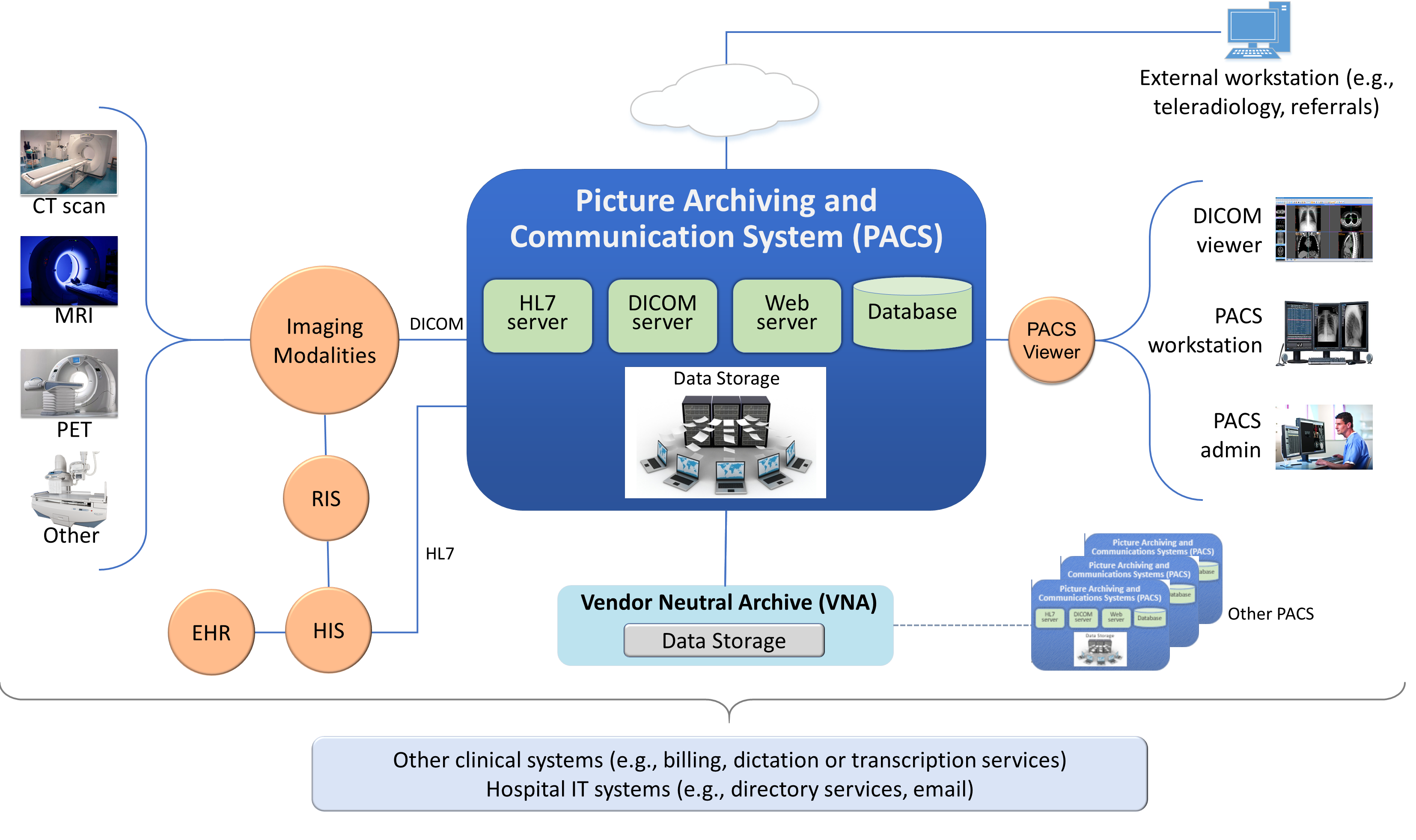
The system for this project is broadly identified as the PACS, though practically, it incorporates a set of processes and other systems that make up a medical imaging ecosystem [B13]. For purposes of this project, and in accordance with NIST SP 800-160 [B5], we consider the individual components as “systems of interest,” noted below:
workstations used to interact with the medical imaging ecosystem
viewer workstations residing within the HDO perimeter
viewer workstations residing external to the HDO perimeter, used by remote care specialists
workstations used by clinical staff to access peripheral systems, such as order entry systems, RIS, HIS, or EHR
modalities, or medical imaging devices that acquire medical images and forward those to the PACS, based on orders typically received from the EHR or HIS and following workflows typically defined by the RIS
clinical systems that interface with modalities and the PACS environment, supporting medical imaging processes such as scheduling, annotations, or reporting
PACS will support interfaces, depicted in Figure 3‑1, as “servers.” These interfaces include the Health Level 7 (HL7) interface that allow clinical systems to interact with the PACS in sharing PHI; the DICOM interface, which represents a communications and medical imaging standard that represents a standard method by which medical imaging modalities interoperate with PACS; and the web server interface, which represents the PACS’ ability to allow clinical interaction with the PACS to retrieve medical images using hypertext transfer protocol (http) via a standard web browser.
a relational database server to manage metadata about the medical images or PACS administration data
PACS and vendor neutral archive (VNA) application servers
In addition to the technology components described above and in the PACS Project Description, we considered other elements, such as stakeholders (system actors) as well as specific business process flows in which those stakeholders may participate. The processes align with profiles established by Integrating the Health Enterprise (IHE) [B4], which this project leveraged to determine process and data flows. The four selected profiles translate to the scenarios described below. Based on the PACS Project Description document, the scenarios of note are Sample Radiology Practice Workflows; Access to Aggregations and Collections of Different Types of Images; Accessing, Auditing, and Monitoring; Image Object Change Management; and Remote Access [B13].
This practice guide does not examine pervasive risks that an HDO may face but rather focuses on those risks specific to the medical imaging ecosystem. While this guide suggests specific requirements for safely and securely hosting PACS, the intent of the guide is not to serve as an omnibus guide for all facets potentially required to operate a secure HDO infrastructure. This guide addresses measures that would enhance the security posture for the overall PACS and medical imaging ecosystem, but there may be elements that HDOs should address beyond the recommendations offered in safeguarding a PACS and the overall medical imaging ecosystem.
3.4.2 System Actors¶
This project considered several roles that interact with the PACS and medical imaging system ecosystem. This project looked at both authorized human and system actors. Human actor roles consist of:
medical imaging technologists
clinicians
clinical systems IT administrators
HTM professionals
IT staff
System actors that interact with the PACS and VNA consist of:
modalities
RIS and HIS
EHRs
The system actor list excludes patients. The actions focused on medical images, which include creation of the image, annotation, storage of the image and annotations, interpretation, and changes to those images. The project limited radiology information systems and EHR systems actions to order entry/scheduling procedures and to pointing to images for reading/viewing. The scenarios below note process flows which describe use case profiles defined by IHE, a body that this project identified as authoritative in defining standard imaging workflow processes [B4].
3.4.3 Use Case Scenarios¶
This project assessed risk for the five scenarios [B13] described below. Considering threats, vulnerabilities, likelihoods, and impacts on medical imaging operations under these scenarios contributed to the risks documented in Section 3.4.6.
These scenarios frame the processes wherein we considered introduction of threats. In addition to the scenario, this document investigates those vulnerabilities, threats, and risks that may be evident based on a holistic view of the architecture, as described in Section 3.4.4, Section 3.4.5, and Section 3.4.6. Within that viewpoint, the scenarios excluded several threats that are relevant for consideration. While this document investigates addressing modality interfaces, it does not examine specific modalities or the risks potentially associated with them. Modality devices themselves are medical devices that may include vulnerabilities or opportunity for systems or data compromise, loss of data integrity, or disruption of service, and HDOs should perform independent risk assessments in addressing those risks.
3.4.3.1 Sample Radiology Practice Workflows¶
Scenario One, shown in Figure 3‑2, starts with registration of a patient who requires an imaging procedure be performed [B13]. For the purposes of this project, the assumption is that the HDO registers the patient into the EHR, determines the patient has appropriate identifiers to be admitted, and the patient is able to receive procedures. The scenario follows the process flow that begins at scheduling the procedure, acquiring the image, and allowing the care team to analyze and diagnose. The assumption is that all modality devices and clinical staff are on-premise, within the boundaries of the HDO. Systems in this sample radiology practice workflow convey patient information using the HL7 [B14] protocol (e.g., patient registration and order entry messages). Medical imaging devices would interact with the PACS/VNA by using DICOM [B2], [B3].
Figure 3‑2 Scenario One: Sample Radiology Practice Workflows
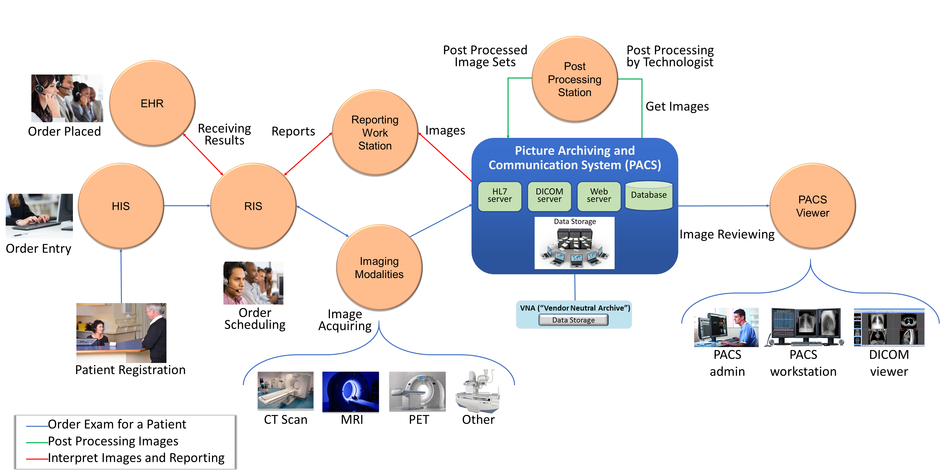
The scenario’s processes are as follows:
Patient Registration: The HDO enters a new patient’s information into an HIS. An HIS may also be referred to as a clinical information system. The function of this process flow is to establish a patient identity within a hospital where one may not previously exist and then administer the patient as appropriate.
Order Entry: Once the HDO establishes a patient identity, a clinician can order a medical imaging procedure for the patient by using some form of computerized physician order entry system.
Order Scheduling: Following a submitted order, clinicians may schedule a medical imaging procedure involving an appropriate medical imaging modality using a RIS.
Image Acquisition: After a clinician creates an order and scheduling has been performed, a clinician performs the imaging procedure using the appropriate modality. Acquisition results in creation of a medical image.
Image Post-Processing: When the modality creates the medical image, imaging technologists will examine the image and may record initial annotations. The image and annotations are then pushed to the PACS.
Image Analysis and Reporting: An imaging clinician may use a viewer workstation to examine the image, analyze, interpret, and diagnose, with subsequent notes pushed to the PACS for reporting.
Stakeholders: medical imaging technologists, clinicians (medical imaging specialists), and medical imaging devices (modalities)
Systems of Interest: order entry, RIS, medical imaging devices, viewer workstations, PACS
Protocols Used: DICOM, web (e.g., hypertext transfer protocol secure [https]), HL7, Host Identity Protocol (HIP)
3.4.3.2 Image Data Access Across the Enterprise¶
Scenario Two, as shown in Figure 3‑3, examines multiple departments that use disparate imaging devices for acquisition and may involve multiple PACS [B13]. The assumption is that different departments have separate clinical staff and different medical imaging goals and may use different means to centralize their medical images. This scenario simulates a hospital, in that radiology is not the only department that uses medical imaging, nor does the radiology department mandate use of its PACS to centralize medical images across a hospital. Aggregation and centralized management remain the goal, but the practice guide describes other components in the ecosystem that enable broader clinical functionality. While PACS implements central medical image storage, access to images is not permitted for all clinical staff.
Figure 3‑3 Scenario Two: Image Data Access Across the Enterprise
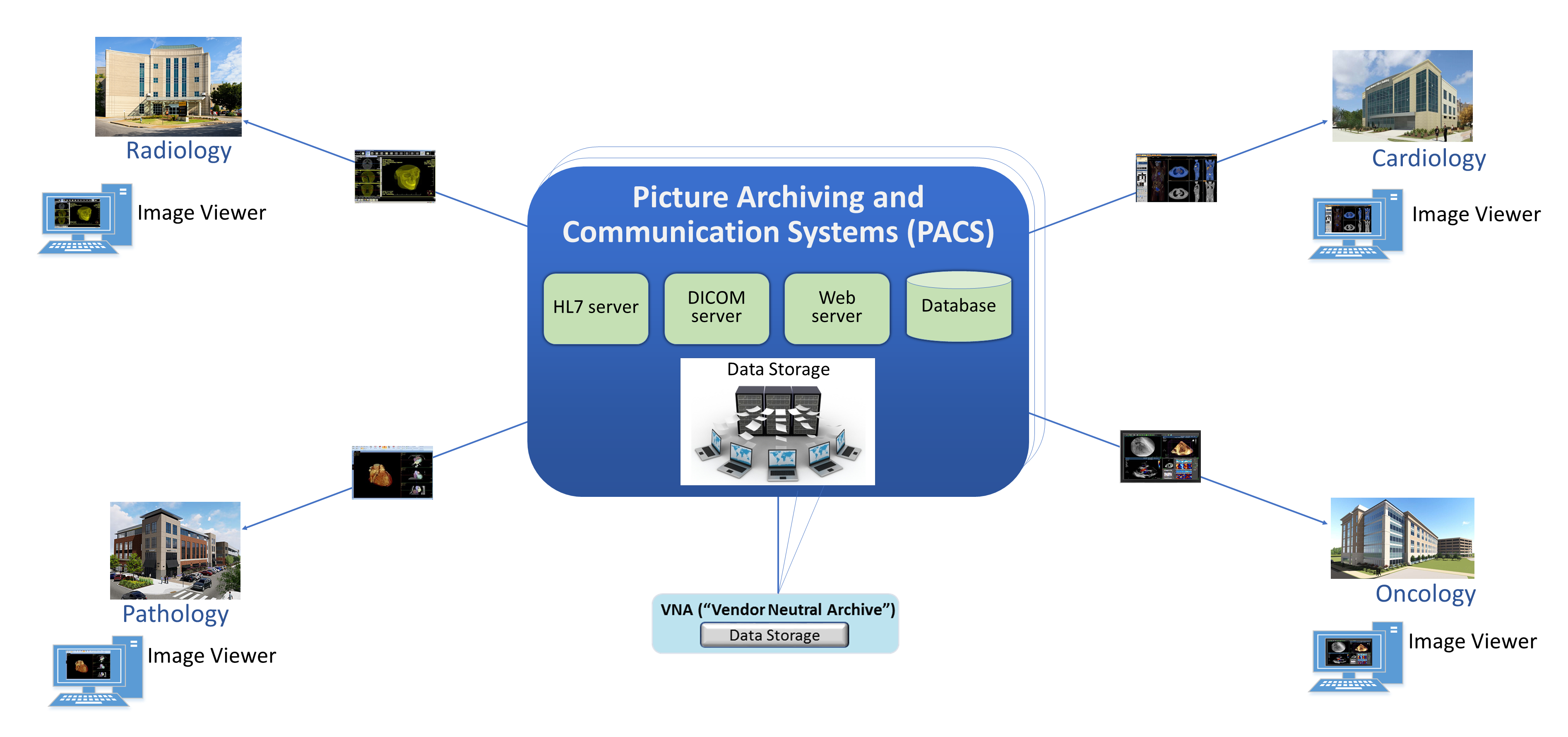
In demonstrating that different groups and technologies are involved, this project shows variables as “_a” or “_b.” This allows us to show the separation between two components that may be similar in function but are separate, e.g., “component_a” versus “component_b.”
Stakeholders: medical imaging staff_a, medical imaging staff_b, healthcare technology management professionals, PACS_a, PACS_b, VNA
Systems of Interest: image viewer_a, image viewer_b, PACS_a, PACS_b, VNA
3.4.3.3 Accessing, Monitoring, and Auditing¶
Scenario Three, as shown in Figure 3‑4, examines the infrastructure required for access control, which includes identity management and authentication for actors who interact with the PACS and VNA environments, as well as logging, auditing, and monitoring actions with the stored information [B13]. The scenario considers those actions where individuals or devices retrieve and view information (Read actions) and introduce new information (Write actions), as well as when individuals or devices modify stored information (Change actions).
Figure 3‑4 Scenario Three: Accessing, Monitoring, and Auditing
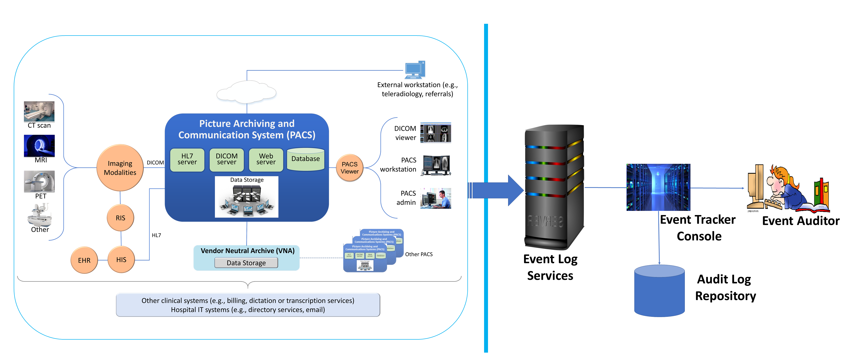
This project established identities for users (humans who interact with the system), as well as for devices and systems. This scenario assumed that individuals have been appropriately identity-proofed and are provisioned accounts with which they may access and use viewer applications. Given that this project provisioned identities and accounts for both human and machine actors, all interactions require authentication. Authentication may involve exchange of passwords, passcodes, biometrics, or cryptographic keys to validate the actor. A log file recorded all transactions, including authentication attempts.
This scenario examines clinical use system interaction and does not address privileged user access. Controls to manage privileged access are discussed in Section 4.1.5.1.1, Privileged Access Management.
Stakeholders: medical imaging staff, medical devices, PACS, VNA
Systems of Interest: directory servers, user account systems, digital certificate servers
Protocols: public key infrastructure (PKI) (associated protocols such as Certificate Management Protocol, http, https), domain name system (DNS), Active Directory
3.4.3.4 Imaging Object Change Management¶
Scenario 4, as shown in Figure 3‑5 , supports the changes that include (1) object rejection due to quality or patient safety reasons, (2) correction of incorrect modality worklist entry selection, and (3) expiration of objects due to data retention requirements [B13]. This diagram depicts the change request process. The scenario considers those actions when an authorized healthcare professional, upon review of the image, determines that errors or qualitative defects found in an image may lead to an inappropriate conclusion.
Figure 3‑5 Scenario Four: Imaging Object Change Management
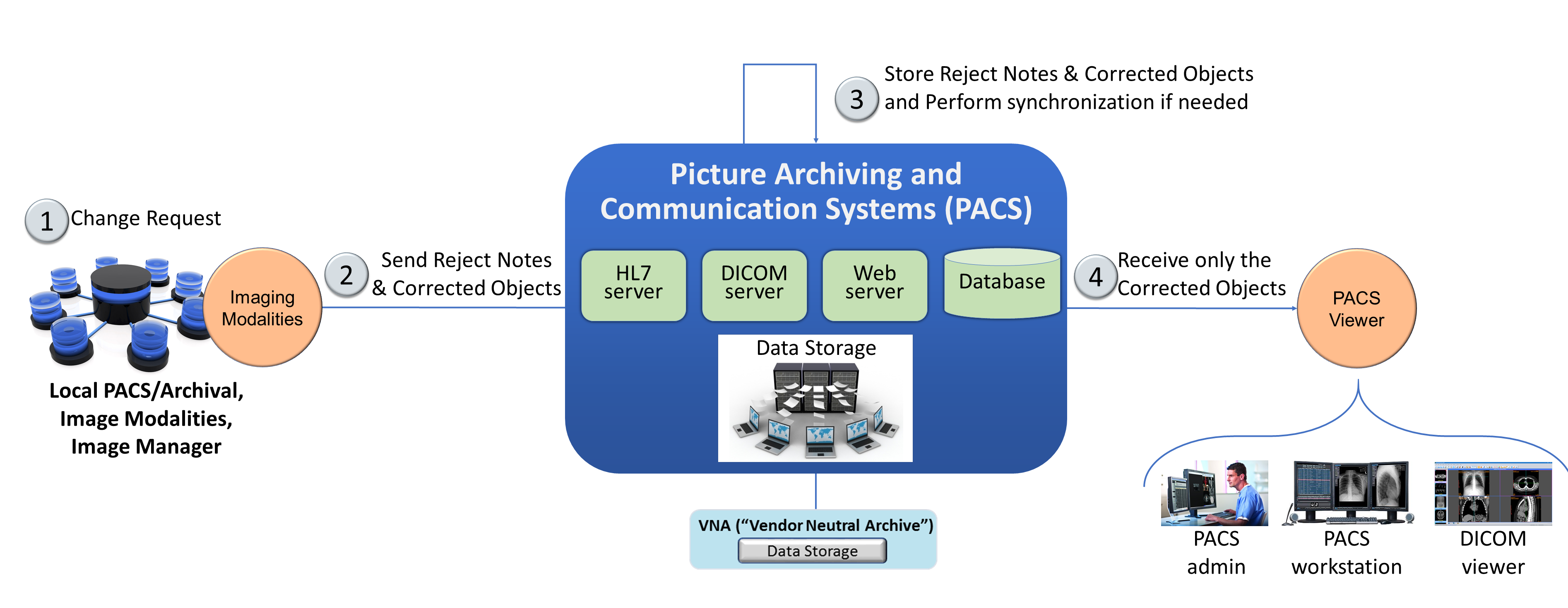
Stakeholders: medical imaging clinicians
Systems of Interest: PACS, VNA
Protocols: HL7, http, https
3.4.3.5 Remote Access¶
Scenario 5, depicted in Figure 3‑6, supports external parties who may need access to the PACS ecosystem. The scenario provides a pathway for IT vendors to provide remote systems support as well as for third-party clinical participants to interact with the PACS. IT vendors may consist of clinical systems support staff who may need to help maintain the PACS or VNA system. Third-party clinical participants may consist of medical imaging specialists or teleradiology specialists who may need to review medical images acquired at the HDO.
Figure 3‑6 Scenario Five: Remote Access
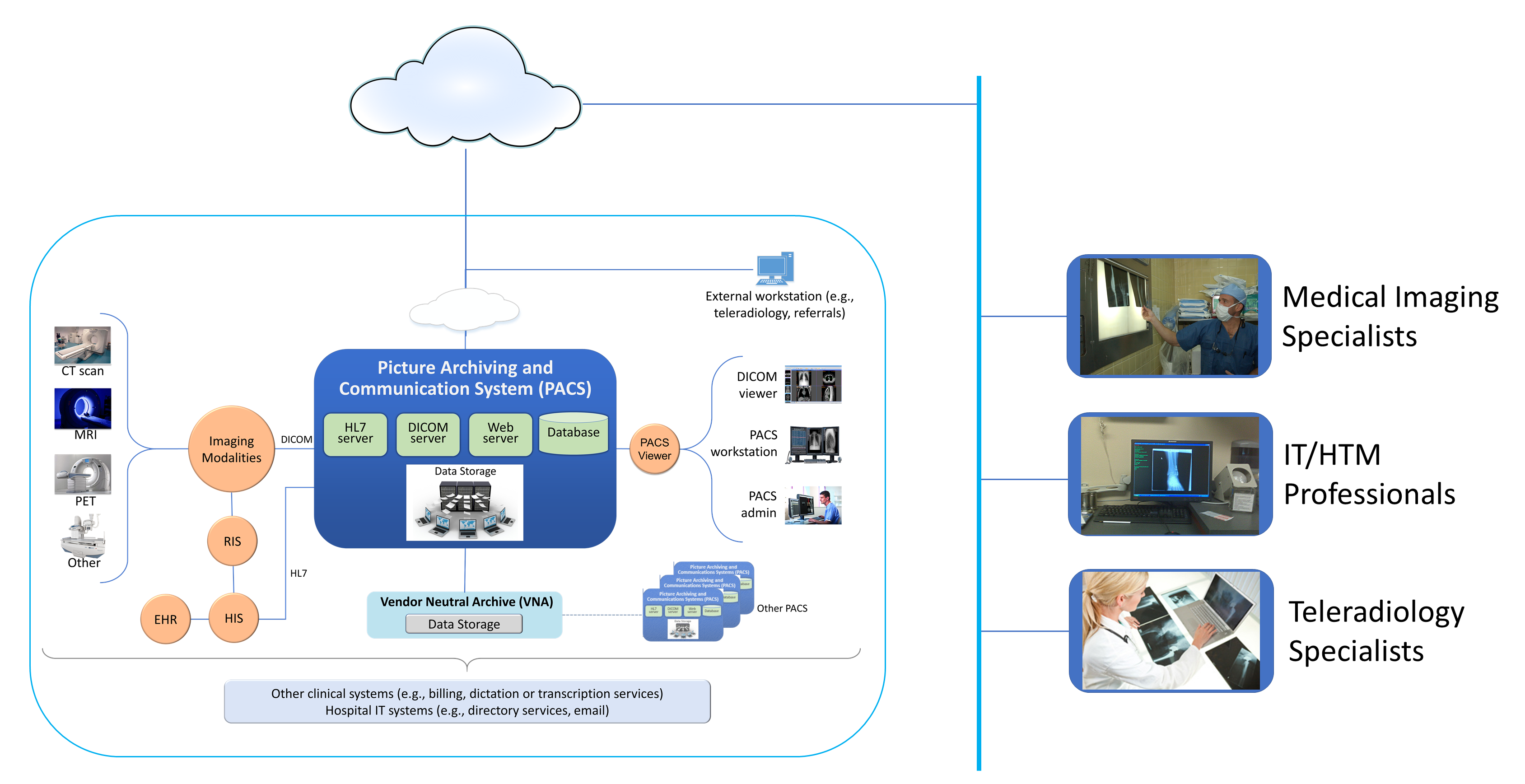
Stakeholders: medical imaging specialists, IT/HTM professionals, teleradiology specialists
Systems of Interest: PACS, VNA
3.4.4 Threats¶
From NIST SP 800-30 Revision 1, “[a] threat is any circumstance or event with the potential to adversely impact organizational operations and assets, individuals, other organizations, or the Nation through an information system via unauthorized access, destruction, disclosure, or modification of information, and/or denial of service” [B10].
In layman’s terms, threats are adverse events that may occur. Threat actors may take actions to leverage vulnerabilities (described in the subsection below). Actions may include compromising credentials and accessing, removing, or changing data or making systems not available for legitimate use. The result of threats is risks [B10]. Table 3‑1 enumerates threats considered within this practice guide.
Table 3‑1 Threats
C/I/A |
Threat Event |
Description |
Unmitigated Likelihood |
|---|---|---|---|
C |
Abuse of credentials or insider threat |
Aberrant behavior from an individual who may have legitimate access to the system; however, they may leverage granted privileges for unintended purposes. |
High |
C |
Credential compromise |
Malicious actor obtains the means to use credentials provisioned for others. Credentials may involve other users or those used by systems for process or data handling. |
High |
C |
Data exfiltration |
Removal of data to an unintended destination. Exfiltration may represent the unauthorized movement of data from one system to uncontrolled physical storage media or may represent movement to uncontrolled virtual destinations such as volatile memory, or to unknown storage such as cloud-hosted or virtual destinations. |
High |
I |
Disruption of data in transit |
Distortion or alteration of data in transit that results in potentially invalid information. The attack type seeks to distort or alter data in mid-communication stream. Received data may be unintelligible or otherwise unreadable when it arrives at the destination. |
Moderate |
I |
Data alteration |
Unauthorized changes to the content of the data. Clinicians may not detect altered information and misinterpret the image. The attack type seeks to make changes when data are in an at-rest state. |
Moderate |
I |
Time synchronization |
System components may rely on synchronizing internal clocks to ensure network session and data integrity. Attacks may seek to alter time stamping or ability for systems to synchronize with an authoritative time source. |
Moderate |
I |
Introduction of malicious software |
Introduction of foreign, unauthorized code into a system. Malicious software deployments may affect servers or workstations or both. Server components: Server components may run unauthorized code. Workstations: Workstations connected to the PACS ecosystem may run unauthorized code. |
High |
I |
Unintended use of service |
Operating systems may consist of services or processes used to support a system’s functionality; individuals with access to the system may perform unintended functions. |
High |
A |
Data storage disruption |
Physical media or file space disruption evidenced by prolonged read/write access times or by corrupted data, thereby causing unavailability of service. |
High |
A |
Network disruption |
Network disruption attacks may take the form of several different approaches. Below are some disruption approaches that this practice guide examines: Denial of service (DoS) or packet flooding: Introduction of above-normal network traffic that saturates network infrastructure components’ ability to deliver network communication appropriately Routing: inefficient network traffic flow DNS or name resolution: Networked hosts are associated with “friendly names” to facilitate interaction; however, name resolution to internet protocol (IP) addressing may be disrupted to make host discovery difficult. Similar or soundalike host and domain names may be introduced to compound confusion. ARP: Address Resolution Protocol (ARP) is a localized means by which hosts resolve IP addresses to media access control (MAC) addresses stored in host tables. Corruption of ARP tables may result in misdirected network traffic or in legitimate devices being unable to connect to the network. |
High |
A |
Backup/recovery disruption |
Measures that organizations use as a fail-over or recovery from a prolonged outage may be compromised, e.g., through introduction of malicious software to backup storage media, inability to read and restore from backup media, or introduction of a supply chain compromise (per above) at a third-party recovery site. High availability or replication scenarios may also be prone to network disruption. |
High |
A |
Supply chain compromise |
System components may be sourced from multiple vendors and may allow introduction of malicious software (noted above). |
High |
3.4.5 Vulnerabilities¶
Table 3‑2 lists identified vulnerabilities that aggregate vulnerabilities identified in NIST SP 800-30 Revision 1 [B10]. As noted in the document, a vulnerability is a deficiency or weakness that a threat source may exploit, resulting in a threat event. The document further describes that vulnerabilities may exist in a broader context, such as in organizational governance structures, external relationships, and mission/business processes. The following table enumerates those vulnerabilities using a holistic approach and represents those vulnerabilities that this project identified and for which it offers guidance. For further description, reference NIST SP 800-30 Revision 1 [B10].
Table 3‑2 Vulnerabilities
Vulnerability Description |
Vulnerability Severity (Qualitative) |
Predisposing Condition |
Pervasiveness of Predisposing Condition (Qualitative) |
|---|---|---|---|
Weak or no system use training |
Moderate |
Workforce may not be aware or may not have received training on appropriate use or configuration of the system. Users may not have sufficient awareness of action consequences. |
High |
Weak or no security training |
High |
Workforce may not be aware of procedures on how to report anomalies. Security teams may not have sufficient training on how to investigate or may not have procedures to address security incidents. |
Moderate |
Deficient supply chain security controls |
High |
Organizations may not be aware of third-party practices or downstream suppliers who may implement technology into the healthcare organization’s environment. |
High |
Deficient separation of duties |
High |
Privileged users may have extended responsibility to ensure system operations. “Super user” identities may allow escalated access to systems, data, and logging features. |
High |
Weak or no identity management |
High |
Organizations may have deficient identity proofing or review processes. |
Moderate |
Weak or no authentication controls |
Very High |
Trivial forms of authentication or using credentials with no authentication requirement. Also found in this category is the use of default credentials that tend to be generally discoverable. |
Very High |
Permissive privilege |
Very High |
Credentials may be established without examining the minimum necessary to perform the required function. As a result, credentials may exist with access to perform actions outside the work scope. Note that permissive privilege may extend to system services whereby services may run as “root” or “administrator,” granting that credential the ability to perform inappropriate actions. |
Very High |
Out-of-date or unmanaged services |
High |
Operating systems, other third-party software, and the PACS application itself include a variety of services, allowing appropriate functionality. Over time, flaws, in the form of bugs (coding errors) or the use of libraries or binaries determined to have security weakness(es), may be discovered and subsequently addressed, resulting in patches or updates. Systems that do not apply those patches and updates may operate with out-of-date services. |
Very High |
Deficient vulnerability management |
Very High |
Organizations may have deficient application and operating system vulnerability scanning and monitoring practices. Flaws or deficiencies may exist in software elements associated with the overall medical imaging system. |
Very High |
Deficient data protection |
High |
Unauthorized individuals may be able to read, modify, delete, or exfiltrate sensitive data. |
High |
Deficient logging and monitoring |
High |
System interactions may not be captured or retained sufficiently for review. Logs, when tracked, may not be reviewed for anomalies on a timely or consistent basis. |
High |
Deficient time synchronization |
Moderate |
Systems may operate on individual internal clocks and may track transactions independently. |
High |
Permissive network boundaries |
High |
Configuration may permit unauthorized network traffic to access sensitive assets. |
Very High |
Lack of network segmentation |
Very High |
Components may operate on the same network or have implied trust with other components. |
Very High |
Lack of network session security |
High |
Network sessions may not be secured. |
High |
Deficient certificate management |
High |
Organizations using certificates to safeguard network sessions (e.g., secure sockets layer [SSL]/Transport Layer Security [TLS] certificates) may allow no certificate, expired certificates, or inappropriate certificates. |
High |
Misconfigured network |
High |
Organizations may have misconfigured network routing or switch settings. |
High |
Misconfigured storage media |
High |
Medical image storage demands are great, and organizations may have misconfigured storage arrays. |
Moderate |
Recovery/restore procedures not tested or not performed |
Very High |
Organizations may not have created or tested recovery procedures. |
High |
The vulnerabilities in the table above represent types of known vulnerabilities, that is, based on vulnerabilities experienced in existing systems and networks.
3.4.6 Risk¶
NIST SP 800-30 Revision 1, Guide for Conducting Risk Assessments, defines risk as “a measure of the extent to which an entity is threatened by a potential circumstance or event, and typically a function of: (i) the adverse impacts that would arise if the circumstance or event occurs; and (ii) the likelihood of occurrence” [B10]. Risk is the adverse impact; that is, risk is the result when a threat (attack) successfully leverages one or more vulnerabilities. As organizations consider risk, they should note that risk is not discrete; that is, a successful attack may involve multiple threats or take advantage of a combination of vulnerabilities. Also, when an organization suffers from an attack campaign, the organization may realize multiple adverse outcomes.
Ransomware or a DoS attack, for example, could adversely impact an HDO by compromising the availability of systems and preventing the HDO from treating patients. This practice guide, however, considers controls and practices that may be appropriate in mitigating or responding to threats affecting confidentiality, integrity, and availability holistically.
Another risk noted below is systemic disruption. Systemic disruption may affect availability and integrity of systems or data. An attacker may compromise the targeted system’s operations, or the attacker may use the targeted system as a platform from which to conduct further attacks across an HDO’s network. Systemic disruption prevents the HDO from treating patients by either making systems inoperative or altering patient data when malware is introduced. This practice guide also considers the specific case of when targeted systems are compromised and used to attack other components within the enterprise.
Table 3‑3 is a list of unmitigated risks applicable to the PACS lab environment, based on the examples of threat types (Section 3.4.4) and vulnerabilities (Section 3.4.5). These risks are offered in terms relating to the healthcare environment, and similar risks can be expected in a typical healthcare environment. Note that the likelihood of threats and vulnerabilities would be based on having implemented effective controls, which would also affect the level of risk determined.
Table 3‑3 Risk
C/I/A |
Risk |
Description |
Risk Level |
|---|---|---|---|
C |
Fraudulent use of health-related information |
Should unauthorized individuals retrieve PHI that includes health insurance information, those actors may be able to submit fraudulent claims and receive reimbursement from a payer for services not rendered to the patient. |
High |
C |
Identity theft and fraudulent use of PHI |
Individuals may receive exfiltrated data to commit identity theft in obtaining healthcare. Fraudulent individuals may receive health services leveraging a victim patient’s information and, as a result, introduce false information into a victim patient’s medical history. This may result in a patient safety concern in that treatments performed for the fraudulent individual would be captured in the victim patient’s history, potentially leading to future inaccurate diagnoses when that patient seeks legitimate care. |
High |
I |
Patient misdiagnosed based on interpretations made from unauthorized changes to medical images |
Unauthorized imaging data alteration compromises data integrity resulting in patient safety risk. Should an individual make an unauthorized image alteration, care providers may make inaccurate diagnoses and therefore delay appropriate treatment. |
High |
A |
Patient diagnoses disrupted, leading to patient safety concerns |
Patients may have conditions that require timely and accurate diagnosis to achieve optimum mortality rates. Communications disruptions that corrupt or deny data may adversely affect this so that care teams are not able to make a timely diagnosis, and patients may have to repeat imaging processes. |
High |
A |
Process disruption due to malware |
PACS or other systems within the ecosystem may succumb to ransomware or other forms of malware, rendering those systems and associated data unavailable. Ransomware may cause complete system unavailability, while other forms of malware may delay processing capability or introduce data integrity risk. As a result, the HDO may not be able to treat patients appropriately or make diagnoses. Delays may result in patient safety concerns. |
High |
A |
Systemic disruption due to component compromise |
Unauthorized individuals may compromise components within the PACS ecosystem and use compromised components as pivot points to attack other parts of the HDO network. This may result in delays in patient care. |
High |
The project identified the risks above as requirements that the lab environment should address. Organizations should note that the tables offered here are samples and notionally representative. Characterizing threats, vulnerabilities, and risk is contextual. HDOs with different security deficiencies or unique threat situations in their systems and network environments may find their categorization to be different from what this practice guide describes. HDOs need to consider their unique profile when categorizing vulnerabilities, threats, and risk. This project identified these risk elements and scored them accordingly, based on the assessment performed on the lab environment.
3.5 Security Control Map¶
As the project considered PACS ecosystem risks, the team performed a mapping to the NIST Cybersecurity Framework [B8], establishing an initial set of appropriate control functions, categories, and subcategories, demonstrating how selected Cybersecurity Framework subcategories map to controls in NIST SP 800-53 Revision 4 [B15]. The table also lists sector-specific standards and best practices from other standards bodies (e.g., the International Electrotechnical Commission [IEC], International Organization for Standardization [ISO]), as well as from the Health Insurance Portability and Accountability Act (HIPAA) [B16], [B17], [B18]. The security control map, shown in Table 3‑4, identifies a comprehensive set of controls, including those specifically implemented in the lab build-out, as well as the pervasive set of controls as described in Appendix C that HDOs should deploy.
Table 3‑4 Security Characteristics and Controls Mapping–NIST Cybersecurity Framework
NIST Cybersecurity Framework v1.1 |
Sector-Specific Standards and Best Practices |
|||||
Function |
Category |
Subcategory |
NIST SP 800-53 Revision 4 |
IEC TR 80001-2-2 |
HIPAA Security Rule |
ISO/IEC 27001 |
IDENTIFY (ID) |
Asset Management (ID.AM) |
ID.AM-1: Physical devices and systems within the organization are inventoried. |
CM-8 PM-5 |
N/A |
45 C.F.R. §§ 164.308(a)(1)(ii)(A ) 164.308(a)(4)(ii)(A ) 164.308(a)(7)(ii)(E ) 164.308(b) 164.310(d) 164.310(d)(2)(iii) |
A.8.1.1 A.8.1.2 |
ID.AM-2: Software platforms and applications within the organization are inventoried. |
CM-8 PM-5 |
N/A |
45 C.F.R. §§ 164.308(a)(1)(ii)(A ) 164.308(a)(4)(ii)(A ) 164.308(a)(7)(ii)(E ) 164.308(b) 164.310(d) 164.310(d)(2)(iii) |
A.8.1.1 A.8.1.2 A.12.5.1 |
||
ID.AM-3: Organizational communication and data flows are mapped. |
AC-4 CA-3 CA-9 PL-8 |
SGUD |
45 C.F.R. §§ 164.308(a)(1)(ii)(A ) 164.308(a)(3)(ii)(A ) 164.308(a)(8) 164.310(d) |
A.13.2.1 A.13.2.2 |
||
ID.AM-4: External information systems are catalogued. |
AC-20 SA-9 |
RDMP |
45 C.F.R. §§ 164.308(a)(1)(ii)(A ) 164.308(a)(4)(ii)(A ) 164.308(a)(7)(ii)(E ) 164.308(b) 164.310(d) 164.310(d)(2)(iii) |
A.11.2.6 |
||
ID.AM-5: Resources (e.g., hardware, devices, data, time, personnel, and software) are prioritized based on their classification, criticality, and business value. |
CP-2 RA-2 SA-14 SC-6 |
SGUD |
45 C.F.R. §§ 164.308(a)(7)(ii)(E ) |
A.8.2.1 |
||
Risk Assessment (ID.RA) |
ID.RA-1: Asset vulnerabilities are identified and documented. |
CA-2 CA-7 CA-8 RA-3 RA-5 SA-5 SA-11 SI-2 SI-4 SI-5 |
MLDP RDMP SGUD |
45 C.F.R. §§ 164.308(a)(1)(i) 164.308(a)(1)(ii)(A ) 164.308(a)(1)(ii)(B ) 164.308(a)(7)(ii)(E ) 164.308(a)(8) 164.310(a)(1) |
A.12.6.1 A.18.2.3 |
|
ID.RA-4: Potential business impacts and likelihoods are identified. |
RA-2 RA-3 SA-14 PM-9 PM-11 |
DTBK SGUD |
45 C.F.R. §§ 164.308(a)(1)(i) 164.308(a)(1)(ii)(A ) 164.308(a)(1)(ii)(B ) 164.308(a)(6) 164.308(a)(7)(ii)(E ) 164.308(a)(8) |
A.16.1.6 Clause 6.1.2 |
||
ID.RA-5: Threats, vulnerabilities, likelihoods, and impacts are used to determine risk. |
RA-2 RA-3 PM-16 |
SGUD |
45 C.F.R. §§ 164.308(a)(1)(ii)(A ) 164.308(a)(1)(ii)(B ) 164.308(a)(1)(ii)(D ) 164.308(a)(7)(ii)(D ) 164.308(a)(7)(ii)(E ) 164.316(a) |
A.12.6.1 |
||
ID.RA-6: Risk responses are identified and prioritized. |
PM-4 PM-9 |
DTBK SGUD |
45 C.F.R. §§ 164.308(a)(1)(ii)(B ) 164.314(a)(2)(i)(C) 164.314(b)(2)(iv) |
Clause 6.1.3 |
||
PROTECT (PR) |
Identity Management and Access Control (PR.AC) |
PR.AC-1: Identities and credentials are issued, managed, verified, revoked, and audited for authorized devices, users, and processes. |
AC-1 AC-2 IA-1 IA-2 IA-3 IA-4 IA-5 IA-6 IA-7 IA-8 IA-9 IA-10 IA-11 |
ALOF AUTH EMRG NAUT PAUT |
45 C.F.R. §§ 164.308(a)(3)(ii)(B ) 164.308(a)(3)(ii)(C ) 164.308(a)(4)(i) 164.308(a)(4)(ii)(B ) 164.308(a)(4)(ii)(C ) 164.312(a)(2)(i) |
A.9.2.1 A.9.2.2 A.9.2.3 A.9.2.4 A.9.2.6 A.9.3.1 A.9.4.2 A.9.4.3 |
PR.AC-2: Physical access to assets is managed and protected. |
PE-2 PE-3 PE-4 PE-5 PE-6 PE-8 |
PLOK TXCF TXIG |
45 C.F.R. §§ 164.308(a)(1)(ii)(B ) 164.308(a)(7)(i) 164.308(a)(7)(ii)(A ) 164.310(a)(1) 164.310(a)(2)(i) 164.310(a)(2)(ii) |
A.11.1.1 A.11.1.2 A.11.1.3 A.11.1.4 A.11.1.5 A.11.1.6 A.11.2.1 A.11.2.3 A.11.2.5 A.11.2.6 A.11.2.7 A.11.2.8 |
||
PR.AC-3: Remote access is managed. |
AC-1 AC-17 AC-19 AC-20 SC-15 |
ALOF AUTH CSUP EMRG NAUT PAUT |
45 C.F.R. §§ 164.308(a)(4)(i) 164.308(b)(1) 164.308(b)(3) 164.310(b) 164.312(e)(1) 164.312(e)(2)(ii) |
A.6.2.1 A.6.2.2 A.11.2.6 A.13.1.1 A.13.2.1 |
||
PR.AC-4: Access permissions and authorizations are managed, incorporating the principles of least privilege and separation of duties. |
AC-1 AC-2 AC-3 AC-5 AC-6 AC-14 AC-16 AC-24 |
ALOF AUTH CNFS EMRG NAUT PAUT |
45 C.F.R. §§ 164.308(a)(3) 164.308(a)(4) 164.310(a)(2)(iii) 164.310(b) 164.312(a)(1) 164.312(a)(2)(i) |
A.6.1.2 A.9.1.2 A.9.2.3 A.9.4.1 A.9.4.4 A.9.4.5 |
||
PR.AC-5: Network integrity is protected (e.g., network segregation, network segmentation). |
AC-4 AC-10 SC-7 |
MLDP NAUT |
45 C.F.R. §§ 164.308(a)(4)(ii)(B ) 164.310(a)(1) 164.310(b) 164.312(a)(1) 164.312(b) 164.312(c) |
A.13.1.1 A.13.1.3 A.13.2.1 A.14.1.2 A.14.1.3 |
||
PR.AC-7: Users, devices, and other assets are authenticated (e.g., single-factor, multi-factor) commensurate with the risk of the transaction (e.g., individuals’ security and privacy risks and other organizational risks). |
AC-7 AC-8 AC-9 AC-11 AC-12 AC-14 IA-1 IA-2 IA-3 IA-4 IA-5 IA-8 IA-9 IA-10 IA-11 |
ALOF AUTH CSUP EMRG NAUT PAUT |
45 C.F.R. § 164.308(a)(4) |
A.9.2.1 A.9.2.4 A.9.3.1 A.9.4.2 A.9.4.3 A.18.1.4 |
||
Data Security (PR.DS) |
PR.DS-1: Data-at-rest is protected. |
MP-8 SC-12 SC-28 |
IGAU MLDP NAUT SAHD STCF TXCF |
45 C.F.R. §§ 164.308(a)(1)(ii)(D ) 164.308(b)(1) 164.310(d) 164.312(a)(1) 164.312(a)(2)(iii) 164.312(a)(2)(iv) |
A.8.2.3 |
|
PR.DS-2: Data-in-transit is protected. |
SC-8 SC-11 SC-12 |
IGAU NAUT STCF TXCF TXIG |
45 C.F.R. §§ 164.308(b)(1) 164.308(b)(2) 164.312(e)(1) 164.312(e)(2)(i) 164.312(e)(2)(ii) 164.314(b)(2)(i) |
A.8.2.3 A.13.1.1 A.13.2.1 A.13.2.3 A.14.1.2 A.14.1.3 |
||
PR.DS-5: Protections against data leaks are implemented. |
AC-4 AC-5 AC-6 PE-19 PS-3 PS-6 SC-7 SC-8 SC-13 SC-31 SI-4 |
AUTH IGAU MLDP PLOK STCF TXCF TXIG |
45 C.F.R. §§ 164.308(a)(1)(ii)(D ) 164.308(a)(3) 164.308(a)(4) 164.310(b) 164.310(c) 164.312(a) |
A.6.1.2 A.7.1.1 A.7.1.2 A.7.3.1 A.8.2.2 A.8.2.3 A.9.1.1 A.9.1.2 A.9.2.3 A.9.4.1 A.9.4.4 A.9.4.5 A.10.1.1 A.11.1.4 A.11.1.5 A.11.2.1 A.13.1.1 A.13.1.3 A.13.2.1 A.13.2.3 A.13.2.4 A.14.1.2 A.14.1.3 |
||
PR.DS-6: Integrity-checking mechanisms are used to verify software, firmware, and information integrity. |
SC-16 SI-7 |
IGAU MLDP |
45 C.F.R. §§ 164.308(a)(1)(ii)(D ) 164.312(b) 164.312(c)(1) 164.312(c)(2) 164.312(e)(2)(i) |
A.12.2.1 A.12.5.1 A.14.1.2 A.14.1.3 A.14.2.4 |
||
Information Protection Processes and Procedures (PR.IP) |
PR.IP-1: A baseline configuration of information technology/ industrial control systems is created and maintained, incorporating security principles (e.g., concept of least functionality). |
CM-2 CM-3 CM-4 CM-5 CM-6 CM-7 CM-9 SA-10 |
CNFS CSUP DTBK NAUT |
45 C.F.R. §§ 164.308(a)(8) 164.308(a)(7)(i) 164.308(a)(7)(ii) |
A.12.1.2 A.12.5.1 A.12.6.2 A.14.2.2 A.14.2.3 A.14.2.4 |
|
PR.IP-3: Configuration change control processes are in place. |
CM-3 CM-4 SA-10 |
CNFS CSUP DTBK |
45 C.F.R. §§ 164.308(a)(8) 164.308(a)(7)(i) 164.308(a)(7)(ii) |
A.12.1.2 A.12.5.1 A.12.6.2 A.14.2.2 A.14.2.3 A.14.2.4 |
||
PR.IP-4: Backups of information are conducted, maintained, and tested. |
CP-4 CP-6 CP-9 |
DTBK PLOK |
164.308(a)(7)(ii)(A ) 164.308(a)(7)(ii)(B ) 164.308(a)(7)(ii)(D ) 164.310(a)(2)(i) 164.310(d)(2)(iv) |
A.12.3.1 A.17.1.2 A.17.1.3 A.18.1.3 |
||
PR.IP-6: Data is destroyed according to policy. |
MP-6 |
DIDT |
45 C.F.R. §§ 164.310(d)(2)(i) 164.310(d)(2)(ii) |
A.8.2.3 A.8.3.1 A.8.3.2 A.11.2.7 |
||
PR.IP-9: Response plans (Incident Response and Business Continuity) and recovery plans (Incident Recovery and Disaster Recovery) are in place and managed. |
CP-2 CP-7 CP-12 CP-13 IR-7 IR-8 IR-9 PE-17 |
DTBK SGUD |
45 C.F.R. §§ 164.308(a)(6) 164.308(a)(6)(i) 164.308(a)(7) 164.310(a)(2)(i) 164.312(a)(2)(ii) |
A.16.1.1 A.17.1.1 A.17.1.2 A.17.1.3 |
||
PR.IP-10: Response and recovery plans are tested. |
CP-4 IR-3 PM-14 |
DTBK SGUD |
45 C.F.R. §§ 164.308(a)(7)(ii)(D ) |
A.17.1.3 |
||
Protective Technology (PR.PT) |
PR.PT-1: Audit/log records are determined, documented, implemented, and reviewed in accordance with policy. |
AU Family |
AUDT |
45 C.F.R. §§ 164.308(a)(1)(i) 164.308(a)(1)(ii)(D ) 164.308(a)(5)(ii)(B ) 164.308(a)(5)(ii)(C ) 164.308(a)(2) 164.308(a)(3)(ii)(A ) |
A.12.4.1 A.12.4.2 A.12.4.3 A.12.4.4 A.12.7.1 |
|
PR.PT-3: The principle of least functionality is incorporated by configuring systems to provide only essential capabilities. |
AC-3 CM-7 |
AUTH CNFS SAHD |
45 C.F.R. §§ 164.308(a)(3) 164.308(a)(4) 164.310(a)(2)(iii) 164.310(b) 164.310(c) 164.312(a)(1) |
A.9.1.2 |
||
PR.PT-4: Communications and control networks are protected. |
AC-4 AC-17 AC-18 CP-8 SC-7 SC-19 SC-20 SC-21 SC-22 SC-23 SC-24 SC-25 SC-29 SC-32 SC-36 SC-37 SC-38 SC-39 SC-40 SC-41 SC-43 |
AUTH MLDP PAUT SAHD |
45 C.F.R. §§ 164.308(a)(1)(ii)(D ) 164.312(a)(1) 164.312(b) 164.312(e) |
A.13.1.1 A.13.2.1 A.14.1.3 |
||
DETECT (DE) |
Anomalies and Events (DE.AE) |
DE.AE-1: A baseline of network operations and expected data flows for users and systems is established and managed. |
AC-4 CA-3 CM-2 SI-4 |
CNFS CSUP MLDP |
45 C.F.R. §§ 164.308(a)(1)(ii)(D ) 164.312(b) |
A.12.1.1 A.12.1.2 A.13.1.1 A.13.1.2 |
DE.AE-2: Detected events are analyzed to understand attack targets and methods. |
AU-6 CA-7 IR-4 SI-4 |
AUDT MLDP |
45 C.F.R. §§ 164.308(a)(1)(i) 164.308(a)(1)(ii)(D ) 164.308(a)(5)(ii)(B ) 164.308(a)(5)(ii)(C ) 164.308(6)(i) 164.308(a)(6)(i) |
A.12.4.1 A.16.1.1 A.16.1.4 |
||
DE.AE-3: Event data are collected and correlated from multiple sources and sensors. |
AU-6 CA-7 IR-4 IR-5 IR-8 SI-4 |
AUDT MLDP SGUD |
45 C.F.R. §§ 164.308(a)(1)(ii)(D ) 164.308(a)(5)(ii)(B ) 164.308(a)(5)(ii)(C ) 164.308(a)(6)(ii) 164.308(a)(8) 164.310(d)(2)(iii) |
A.12.4.1 A.16.1.7 |
||
DE.AE-5: Incident alert thresholds are established. |
IR-4 IR-5 IR-8 |
DTBK MLDP SGUD |
45 C.F.R. §§ 164.308(a)(1)(i) 164.308(a)(1)(ii)(D ) 164.308(a)(5)(ii)(B ) 164.308(a)(5)(ii)(C ) 164.308(6)(i) 164.308(a)(6)(i) |
A.16.1.4 |
||
Security Continuous Monitoring (DE.CM) |
DE.CM-1: The network is monitored to detect potential cybersecurity events. |
AC-2 AU-12 CA-7 CM-3 SC-5 SC-7 SI-4 |
AUDT CNFS CSUP MLDP NAUT |
45 C.F.R. §§ 164.308(a)(1)(i) 164.308(a)(1)(ii)(D ) 164.308(a)(5)(ii)(B ) 164.308(a)(5)(ii)(C ) 164.308(a)(2) 164.308(a)(3)(ii)(A ) |
N/A |
|
DE.CM-3: Personnel activity is monitored to detect potential cybersecurity events. |
AC-2 AU-12 AU-13 CA-7 CM-10 CM-11 |
AUDT EMRG PAUT |
45 C.F.R. §§ 164.308(a)(1)(ii)(D ) 164.308(a)(3)(ii)(A ) 164.308(a)(5)(ii)(C ) 164.312(a)(2)(i) 164.312(b) 164.312(d) |
A.12.4.1 A.12.4.3 |
||
DE.CM-4: Malicious code is detected. |
SI-3 SI-8 |
IGAU MLDP |
45 C.F.R. §§ 164.308(a)(1)(ii)(D ) 164.308(a)(5)(ii)(B ) |
A.12.2.1 |
||
DE.CM-7: Monitoring for unauthorized personnel, connections, devices, and software is performed. |
AU-12 CA-7 CM-3 CM-8 PE-3 PE-6 PE-20 SI-4 |
AUDT PAUT PLOK |
45 C.F.R. §§ 164.308(a)(1)(ii)(D ) 164.308(a)(5)(ii)(B ) 164.308(a)(5)(ii)(C ) 164.310(a)(1) 164.310(a)(2)(ii) 164.310(a)(2)(iii) |
A.12.4.1 A.14.2.7 A.15.2.1 |
||
DE.CM-8: Vulnerability scans are performed. |
RA-5 |
MLDP PLOK |
45 C.F.R. §§ 164.308(a)(1)(i) 164.308(a)(8) |
A.12.6.1 |
||
RESPOND (RS) |
Response Planning (RS.RP) |
RS.RP-1: Response plan is executed during or after an event. |
CP-2 CP-10 IR-4 IR-8 |
DTBK MLDP SGUD |
45 C.F.R. §§ 164.308(a)(6)(ii) 164.308(a)(7)(i) 164.308(a)(7)(ii)(A ) 164.308(a)(7)(ii)(B ) 164.308(a)(7)(ii)(C ) 164.310(a)(2)(i) 164.312(a)(2)(ii) |
A.16.1.5 |
RECOVER (RC) |
Recovery Planning (RC.RP) |
RC.RP-1: Recovery plan is executed during or after a cybersecurity incident. |
CP-10 IR-4 IR-8 |
DTBK MLDP SGUD |
45 C.F.R. §§ 164.308(a)(7) 164.308(a)(7)(i) 164.308(a)(7)(ii) 164.308(a)(7)(ii)(C ) 164.310(a)(2)(i) 164.312(a)(2)(ii) |
A.16.1.5 |
3.6 Technologies¶
Table 3‑5 lists all the products and technologies used in this project and provides a mapping among the generic application term, the specific product used, and the security control(s) that the product provides or supports. Refer to Table 3‑4 for an explanation of the NIST Cybersecurity Framework subcategory codes.
The Products and Technology table represents the solutions provided by the project collaborative partners and applied to the lab environment. This project selected these solutions based on their alignment to the NIST Cybersecurity Framework control objectives. Organizations should note that they may achieve control objectives through any number of means, including open-source or internally developed approaches.
Table 3‑5 Products and Technologies
Component/ Capability |
Product |
Function |
NIST Cybersecurity Framework Subcategories |
|---|---|---|---|
PACS and VNA |
Hyland Acuo Vendor Neutral Archive Version 6.0.4 |
|
PR.AC-1
PR.AC-4
PR.DS-2
PR.IP-4
PR.PT-1
|
Hyland NilRead Enterprise Version 4.3.31.98805 |
|
PR.AC-1
PR.DS-2
PR.PT-1
|
|
Hyland PACSgear Version 4.1.0.64 |
|
PR.AC-1
PR.DS-2
PR.PT-1
|
|
Philips Enterprise Imaging Domain Controller |
|
PR.AC-1 |
|
Philips Enterprise Imaging IntelliSpace PACS |
|
PR.DS-2
PR.IP-4
PR.PT-1
|
|
Philips Enterprise Imaging Universal Data Manager |
|
PR.DS-2
PR.IP-4
PR.PT-1
|
|
DCM4CHEE Open-Source Clinical Image and Object Management Enterprise Version DCM4CHEE-arc-light5 v. 5.21.0 |
|
N/A |
|
DVTk Modality Emulator |
|
N/A |
|
DVTk RIS Emulator |
|
N/A |
|
Asset Management |
Virta Labs BlueFlow Version 2.6.4 |
|
ID.AM-1
ID.AM-2
ID.AM-4
ID.AM-5
ID.RA-1
ID.RA-5
PR.IP-1
|
Clearwater Information Risk Management Analysis |
|
ID.AM-1
ID.AM-2
ID.AM-4
ID.AM-5
|
|
Tripwire Enterprise Version 8.7 |
|
ID.RA-1
ID.RA-5
PR.DS-6
PR.IP-1
PR.IP-3
PR.PT-3
|
|
Enterprise Domain and Identity Management |
Active Directory |
|
PR.AC-1
PR.AC-4
PR.AC-7
PR.PT-3
|
DigiCert PKI Platform |
|
PR.AC-1
PR.AC-4
PR.AC-7
PR.DS-2
|
|
Symantec Validation and ID Protection Version 9.8.4 Windows |
|
PR.AC-1
PR.AC-3
PR.AC-7
|
|
Network Control and Security |
Cisco Firepower Management Center (FMC) 6.3.0 |
|
PR.AC-5
PR.PT-4
|
Cisco Firepower Threat Defense (FTD) 6.3.0 |
|
PR.AC-5
PR.PT-4
|
|
Tempered Networks Identity Defined Networking (IDN) Conductor and HIPswitch Version 2.1 |
|
PR.AC-5
PR.DS-2
PR.PT-4
|
|
Zingbox IoT Guardian |
|
ID.AM-3
ID.RA-1
ID.RA-5
DE.AE-1
DE.AE-2
DE.AE-3
DE.AE-5
DE.CM-1
DE.CM-7
|
|
Forescout CounterACT 8 |
|
PR.AC-4
PR.AC-7
PR.PT-4
DE.AE-1
DE.AE-3
DE.CM-1
DE.CM-7
|
|
Symantec Endpoint Detection and Response (EDR) Version 4.1.0 |
|
DE.CM-1
DE.CM-4
|
|
Cisco Stealthwatch Version 7.0.0 |
|
ID.AM-3
DE.AE-1
DE.AE-2
DE.AE-3
DE.AE-5
DE.CM-1
DE.CM-3
DE.CM-7
|
|
Secure Remote Access |
TDi Technologies ConsoleWorks Version 5.1-0u1 |
|
PR.AC-3
PR.AC-7
|
Endpoint Protection and Security |
Symantec Data Center Security: Server Advanced (DCS:SA) Version 6.7 |
|
PR.DS-6
PR.IP-3
|
Symantec Endpoint Protection Version 14.2 |
|
DE.CM-4
DE.CM-8
|
|
Cloud Storage |
Microsoft Azure Block Blob Storage account |
|
PR.AC-1
PR.AC-4
PR.AC-7
PR.DS-1
PR.DS-2
PR.DS-6
PR.PT-4
|
Microsoft Azure Security Center Standard |
|
ID.RA-1
ID.RA-5
DE.AE-1
DE.AE-2
DE.CM-1
DE.CM-8
|
|
Microsoft Azure Key Vault Premium |
|
PR.AC-1
PR.DS-1
|
|
Microsoft Azure Monitor |
|
PR.AC-1
PR.IP-1
PR.PT-1
DE.CM-7
|
|
Microsoft Azure Active Directory |
|
PR.AC-1
PR.AC-4
PR.AC-7
PR.PT-3
DE.CM-3
|
|
Microsoft Azure Private Link |
|
PR.DS-2
PR.PT-4
|
4 Architecture¶
When designing the PACS reference architecture, this practice guide implements the PACS environment within an HDO enterprise. NIST SP 1800-8, Securing Wireless Infusion Pumps in Healthcare Delivery Organizations describes implementing the HDO enterprise infrastructure and a network zone approach. This practice guide leverages that larger enterprise described in NIST SP 1800-8 and in Section 4.1 identifies zones in as they relate to PACS. This practice guide extends data storage by provisioning a cloud storage provider for long-duration storage.
The FDA defines the PACS as “a device that provides one or more capabilities relating to the acceptance, transfer, display, storage, and digital processing of medical images. Its hardware components may include workstations, digitizers, communications devices, computers, video monitors, magnetic, optical disk, or other digital data storage devices, and hardcopy devices. The software components may provide functions for performing operations related to image manipulation, enhancement, compression or quantification” [B19]. In addition to the PACS, this project used VNA solutions that meet the Food and Drug Administration’s definition of PACS but have other features that HDOs may use to enhance their overall image management ecosystem. This guide recognizes that healthcare systems interoperate and that the reference architecture needs to accommodate a broad view of the medical imaging ecosystem.
4.1 Architecture Description¶
This practice guide’s architecture looks at components from three primary layers:
business, where we deployed our core medical imaging components
security, where we implemented security tools
infrastructure, which represents our network
Figure 4‑1 illustrates the project’s high-level architecture.
Figure 4‑1 High-Level PACS Architecture
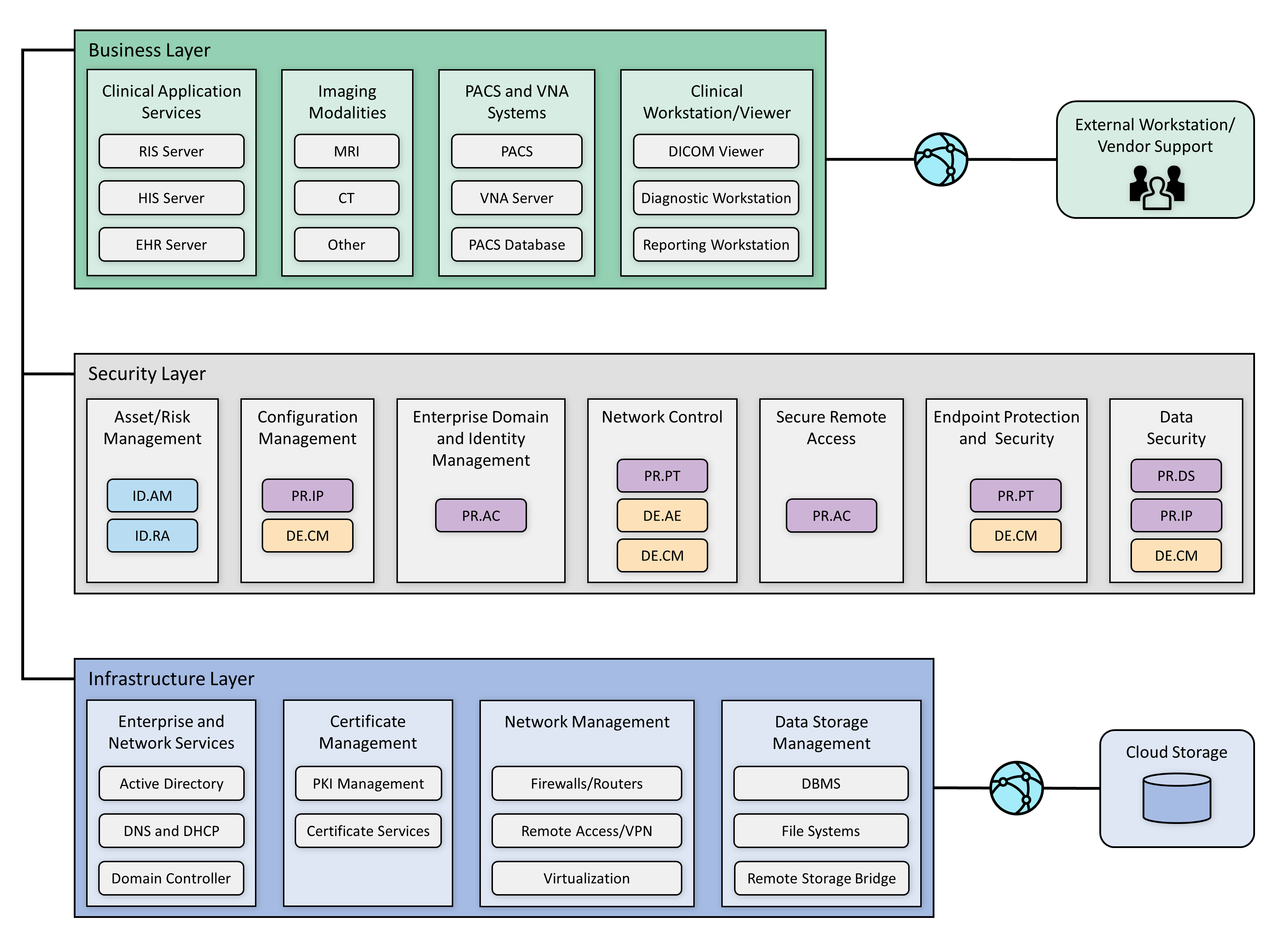
A PACS ecosystem includes components that address data in transit, data at rest, and data processing and provides applications allowing authorized individuals to review and interact with data stored in their respective systems. Clinical systems are also part of our architecture, including imaging modalities and applications such as the RIS, that each play business process roles that interact with the PACS and VNA. Medical imaging generally uses standard protocols, including DICOM.
DICOM is an international standard specific to storing, retrieving, printing, processing, and displaying medical information. The DICOM standard assures medical image information operability and provides a common standard, allowing different medical imaging product vendors to integrate their solutions into the medical imaging ecosystem [B2], [B3].
In addition to the DICOM standard, PACS uses the HL7 protocol for clinical documentation and image reporting. HL7 defines a markup standard for exchanging health information in a structured format by using a clinical document architecture [B20].
This document examines standard technology components in addition to the protocols noted above. Central to PACS are storage media, the network infrastructure, supporting operating systems, as well as application servers to support information exchange (e.g., HL7, DICOM, and web servers).
The architecture described for this project implemented several zones composed of:
Clinical application services consist of systems such as the EHR, order entry, health information systems, and others used by patient care teams in recording information during patient treatment.
Clinical workstation/viewer establishes a network zone that segregates clinical workstations from the nonclinical production network. Clinical workstations are special-purpose devices used to interact with clinical systems. Those devices may use vendor-specified operating systems, applications, and configurations that vary from the HDO standard build. Configuration and patch management may be asynchronous with how the HDO manages its productivity or standard build systems.
Enterprise network services are grouped into a separate zone for enterprise operations. Enterprise operations include services such as email communications, Active Directory, DNS, and security services that include certificate management.
Imaging modalities provide a zone for departments using imaging equipment, generally termed as modalities. These are medical devices using operating systems that are not consistent with an HDO’s baseline. Configuration and patch management are likely asynchronous with how the HDO manages its productivity or standard build systems. For purposes of this project, this zone includes emulated modalities. This project used simulation software to generate medical images.
PACS and VNA systems segregate the PACS and VNA applications from clinical applications, general workstations, and storage media. This zone provides the higher-level application functionality to interact with aggregated medical images.
Data storage management isolates large-scale storage, such as storage area networks (SANs) or network-attached storage (NAS) devices. Data stored in this zone may be unstructured, large files that may contain sensitive, personal, or PHI.
Cloud storage is external to the HDO infrastructure and represents the use of a third-party cloud storage provider where medical images are archived.
Vendor Net supports remote connectivity, e.g., remote vendor support. This zone segregates external network traffic used when vendors may need to perform maintenance on systems or other equipment while the support engineer is off premises.
4.1.1 PACS Ecosystem Components¶
The PACS ecosystem includes those components that support the clinical processes associated with medical imaging acquisition, review, annotation, and storage. Clinical applications, such as the RIS, generate image acquisition worklists and apply worklists to associated modalities. Modalities retrieve worklists from the RIS. The lab environment included two distinct PACS and a VNA systems and deployed image viewing software associated with those systems on workstations to review and annotate medical images. In building the lab environment, this project emulated some of the components rather than obtaining full-scale solutions. This project emulated both modalities and an RIS. The project also used a mobile phone device for document scanning. Figure 4‑2 depicts a high-level view of these components and how we approached implementing them in the lab environment.
Figure 4‑2 PACS Ecosystem Components
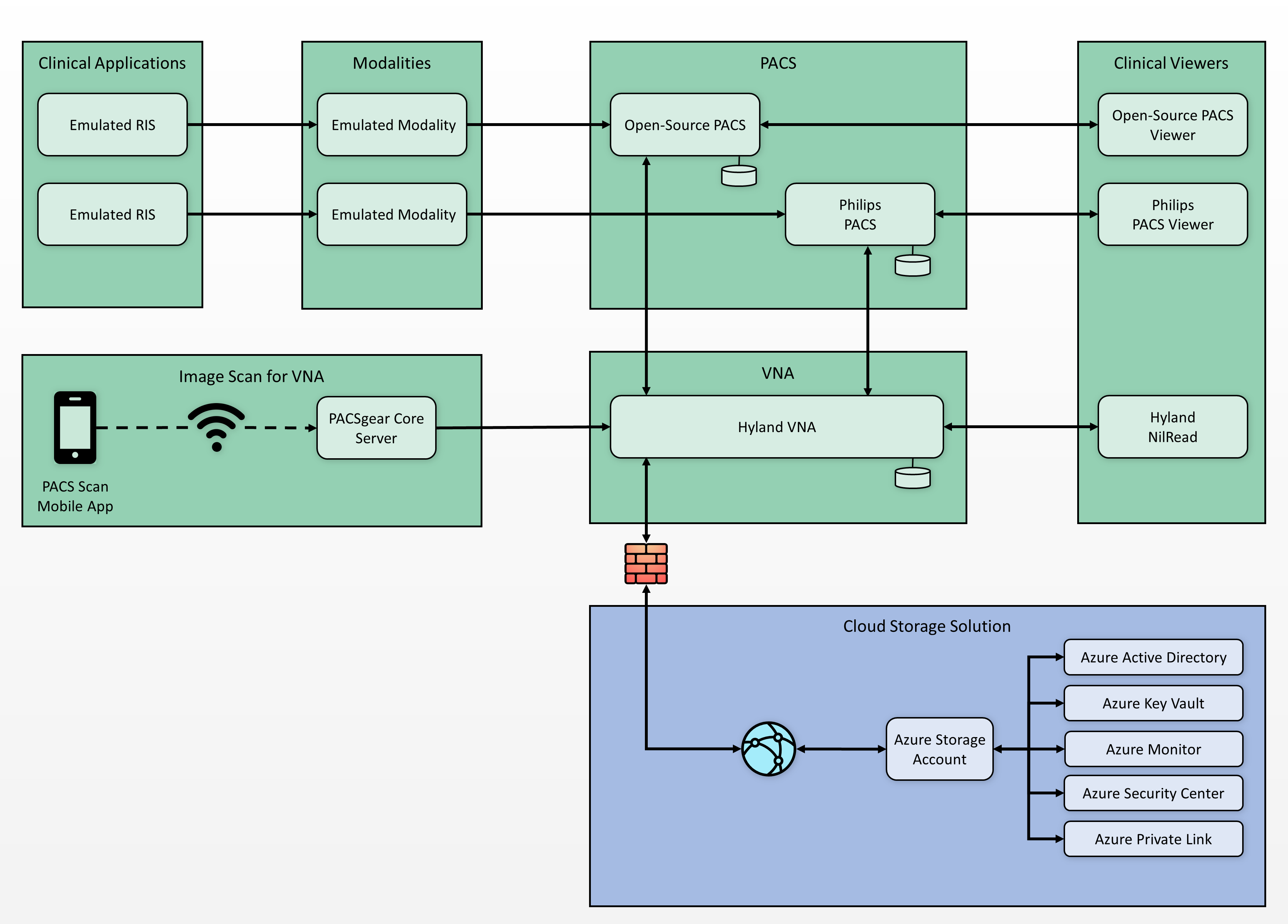
The open-source tool from DVTk (https://www.dvtk.org) includes packages that allowed this project to emulate medical imaging modalities and an RIS. The project deployed two instances of the RIS Emulator into the clinical application services zone. The DVTk RIS Emulators associate the modalities with separate PACS and provide worklists for those modalities associated with two respective PACS, reflective of an HDO that may operate multiple PACS. The project used Philips IntelliSpace PACS and DCM4CHEE (https://www.dcm4che.org/), an open-source PACS, to support this premise. Hyland Acuo VNA was deployed to model HDOs using this technology.
This project deployed the modalities to a modalities network zone. Using emulated modalities allowed the project team to simulate DICOM image acquisition, interaction with the RIS, and transferring images from the modality device to the PACS and VNA for storage and management. The project used an iPhone to operate the PACS Scan Mobile app provided by Hyland, connecting to a PACSgear Core Server. The iPhone was treated as a modality, with the application facilitating document scanning and, through the PACSgear server, transferring mobile-acquired images to the VNA.
4.1.2 Data and Process Flow¶
For this project, we examined data and process flows as described in Section 3.4.1, Establishing the Risk Context, that include the following scenarios:
sample radiology practice flows
access to aggregations and collections of different types of images
accessing monitoring and auditing
image object change management
remote access
The scenarios identify medical imaging acquisition processes, starting with scheduling the patient for a procedure, and follow the life cycle through when the patient interacts with an imaging device to when a medical imaging specialist processes and forwards the annotated image to a clinician for interpretation and diagnosis. Scenarios also examine processes after direct patient interaction, such as when authorized individuals access images for later review or when images need to be updated.
Figure 4‑3 shows a simplified data communication flow in the PACS ecosystem.
Figure 4‑3 PACS Ecosystem Data Communication Flow
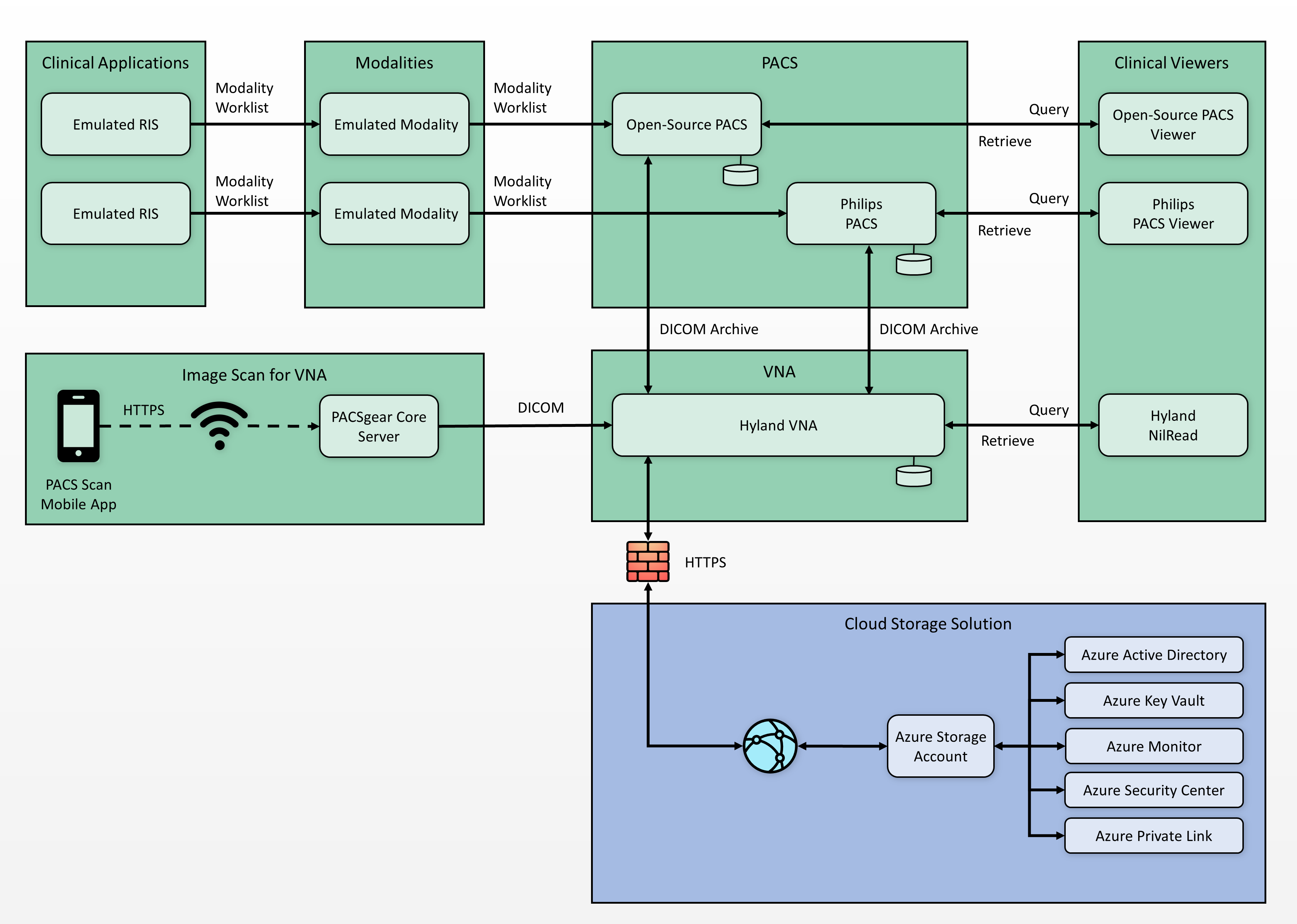
A typical radiology department workflow may begin with patient registration and admission, followed by a physician ordering an imaging procedure. The order is entered into a RIS to create a worklist. A medical imaging technologist attends to a patient and performs the image capture procedure. The medical imaging technologist may make annotations for a physician’s review. The system forwards that information to a PACS or VNA. A physician retrieves the images from the PACS or VNA and uses an image viewing station to review the images and document findings and diagnoses. On completion, the physician transfers the information back to the PACS. Results may cross-reference with the EHR system.
4.1.3 Security Capabilities¶
This practice guide built upon the zoned network architecture described in NIST SP 1800-8, Securing Wireless Infusion Pumps in Healthcare Delivery Organizations [B21]. Network zoning provided a baseline upon which engineers deployed the medical imaging ecosystem infrastructure. The practice guide identified and deployed security capabilities to the environment, consisting of the following:
asset and risk management
enterprise domain and identity management
access control
privileged access controls
user authentication
device and system authentication
data access control
network control and security
network segmentation and virtual local area networks (VLANs)
firewall and control policies
microsegmentation
anomalies and events detection (behavioral analytics)
intrusion detection and prevention systems
endpoint protection and security
device hardening and configuration
malware detection
data security
data encryption (at-rest)
data encryption (in-transit)
secure remote access
While the project takes a holistic approach when evaluating the medical imaging environment, the control scope noted in this practice guide is bound to those elements that are inherently or highly supportive of acquiring, interpreting, or storing medical images. An HDO’s infrastructure is larger in scope than that used to support the medical imaging environment. An HDO may and should implement additional pervasive controls to secure the overall environment. This document references pervasive controls not implemented during this project and assumes an organization will implement appropriate controls to address its broader risk profiles. Refer to Appendix C for details. Figure 4‑4 below depicts contextual controls deployed in the project’s test build.
Figure 4‑4 Base Controls on Test Build Components
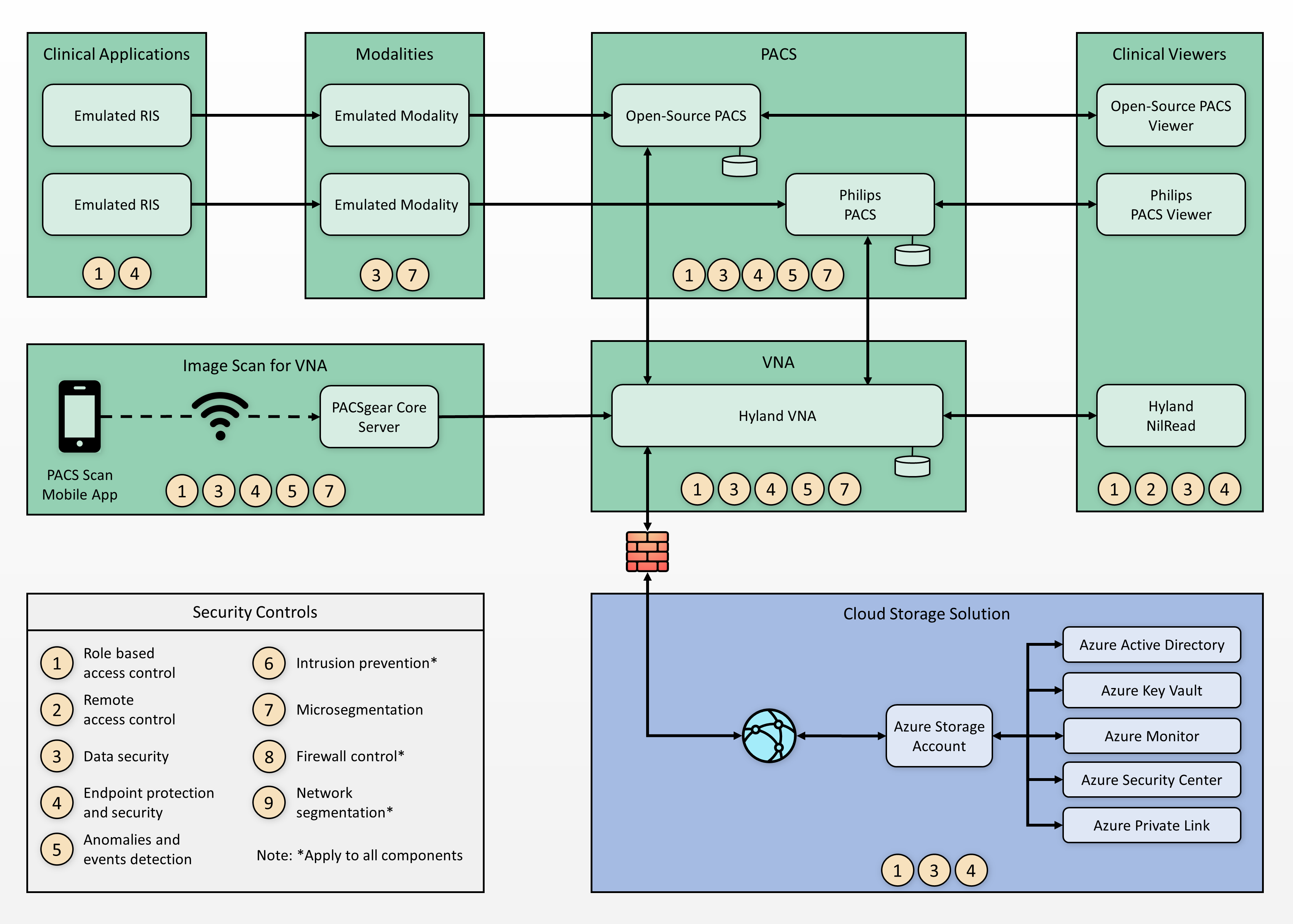
4.1.4 Asset and Risk Management¶
Asset management is a critical control that aligns with the function known as Identify in the NIST Cybersecurity Framework [B8]. This project assumes a pervasive control exists, such as a governance, risk and compliance (GRC) solution. The HDO manages IT general assets through the GRC solution. Medical imaging devices may fall outside the scope of IT general assets for many HDOs. For this reason, this project implemented Virta Labs BlueFlow for asset and inventory management for medical imaging devices. BlueFlow captures inventory, configuration, and patch management information [B16], [B22], [B23].
4.1.5 Enterprise Domain and Identity Management¶
This project looked at identity management controls as including several concepts that encompass identity proofing, credentialing, and providing a means to authenticate devices and systems. Human actors (clinical, IT administrative, and general HDO staff), medical devices, and systems may have identities established within the HDO. An identity is a broader concept than credentials or user accounts. This project assumed that HDOs perform adequate identity proofing and provisioning. This involves processes that allow HDOs to verify that an individual is who they claim to be, also ensuring that the individual has appropriate credentials to interact with clinical systems and medical imaging information. Regarding provisioning, this project assumed that following identity proofing, the organization can create and securely deliver credentials (e.g., user accounts in which the individual can select and update passwords or challenge responses known only to that individual).
Identities may include multiple user accounts or access mechanisms that may be applied. For example, an individual may have a job function as an IT administrator. As a member of the HDO workforce, they may be credentialed to access certain systems such as email or productivity software. They may also have access to separate privileged accounts to be used when they perform IT administrative duties. Having separate credentials established based on functionality or role is a common practice in healthcare and provides a form of separation of duties.
Medical devices and systems may also have identities, that are authenticated using digital certificates, keys, or other unique identifiers such as host identifiers or MAC addresses.
4.1.5.1 Access Control¶
Access control is applied contextually, based on the identity type. This project implemented access control for privileged users, clinical users, devices, and systems. Subsections below provide more detail on the project’s approach.
4.1.5.1.1 Privileged Access Management¶
Privileged access includes those credentials that have permissions to systems that are greater than standard users. Privileged access accounts often allow greater visibility of resources stored on systems and may allow modifying configuration settings or permitting installation of software components. One measure that this guide implements is segregating privileged access accounts. These accounts were unique and distinct from those accounts we created that were able to access information via DICOM viewer applications. When activities required privileged access, access actions routed through lab environment’s TDi ConsoleWorks implementation, which enforced the project’s multifactor authentication solution.
For further guidance on privileged account management, HDOs should reference NIST SP 1800-18, Privileged Account Management for the Financial Services Sector [B24]. While the document identifies solutions for financial services, the underlying technology solution applies to healthcare and other sectors.
4.1.5.1.2 User Authentication¶
User authentication involves the use of different factors. Factors are characteristics by which a user may be able to assert their identity. In many cases, users are authenticated using a single factor (e.g., a username and password combination). One means to strengthen single-factor authentication is to use pass phrases rather than passwords. This approach reduces the possibility that a malicious actor may be able to brute-force-attack the credential [B25].
Another aspect that HDOs may consider is to implement multifactor authentication where appropriate or feasible. Multifactor authentication includes a need to pass two or more factors that represent something a user knows, has, or is. Memorized passwords or pass phrases represent factors that a user knows. Including other factors, such as something a user has, which may represent a physical token; or something a user is, such as biometrics that include fingerprints, retinal, or facial scans, would provide greater assurance that the user is whom they claim to be. Multifactor authentication may not be implementable in all cases, and HDOs may need to determine their risk tolerance and implementation practicality when considering enhancing their authentication models [B26].
4.1.5.1.3 Device and System Authentication¶
For this project, we emulated medical imaging devices and implemented the HIP. Emulated modality devices authenticated to a HIPswitch, routing modality traffic across a HIP-secured software-defined network. For further information, refer to the discussion in Section 4.1.6.3, Microsegmentation.
For systems authentication within the HDO, this project used digital certificates and keys. This project deployed digital certificates to the PACS and VNA servers as well as to a mobile device where we installed software used to scan documents and images that would be added to our medical imaging store. Authentication between VNA servers and cloud data storage is achieved using access keys.
This practice guide uses digital certificates to secure network sessions using a key management solution provided by the cloud provider. The HDO configures key management to maintain private key control. However, this project did not implement a data security manager or hardware security manager on premise.
4.1.5.1.4 Data Access Control¶
PACS and VNA solutions often support a “multitenant” concept to allow for different departments, clinics, or hospitals within a larger healthcare system. These applications may implement or integrate with directory services that allow solutions administrators to provide access based on role or business function. This project used role-based access control capabilities found in the Philips IntelliSpace and Hyland Acuo systems. For this project, the VNA plays a vital role for managing medical images across the simulated HDO. The VNA manages, retrieves, and stores medical images to a cloud storage provider. Access to the data in the storage account is managed through access keys and policies.
4.1.6 Network Control and Security¶
This project continued with the network zoning and segmentation concepts established in NIST SP 1800-8 and built on those concepts by implementing several tools to advance protective and detective capabilities. As examples of these enhancements, this project deployed a next-generation firewall, introduced microsegmentation, and implemented behavioral analytics in its network control and security in its approach. Subsections below provide additional information on these topics.
4.1.6.1 Network Segmentation and VLANs¶
The PACS ecosystem is made up of a variety of different devices with independent requirements to ensure proper functionality. While some devices may require network access to remote services, others may operate effectively with limited connectivity outside their subnet. To meet these needs, we implemented VLANs to segment the PACS network based on devices of similar needs and functionalities. This complies with the concept of network zoning introduced in NIST SP 1800-8 [B21]. With this approach, we eliminated inherent trust between VLANs. The project allowed devices to communicate with only trusted devices based on carefully crafted network policies.
The PACS project implemented the architecture described in Section 4.1 by constructing a network that was segmented into VLANs. The project limited the implementation to the main components necessary for the PACS ecosystem. The project segmented the network into the following VLANs:
vendor net
enterprise services
clinical viewers
PACS A
PACS B
modalities
clinical applications
guest services
databases
remote storage
security services
This project established segmentation through virtualization, with separate subnets implemented for each VLAN listed above. The project placed each VLAN behind a router/firewall that implements policies defined by VLAN’s purpose. Figure 4‑5 below depicts the network architecture.
Figure 4‑5 NCCoE Lab Environment Network Architecture
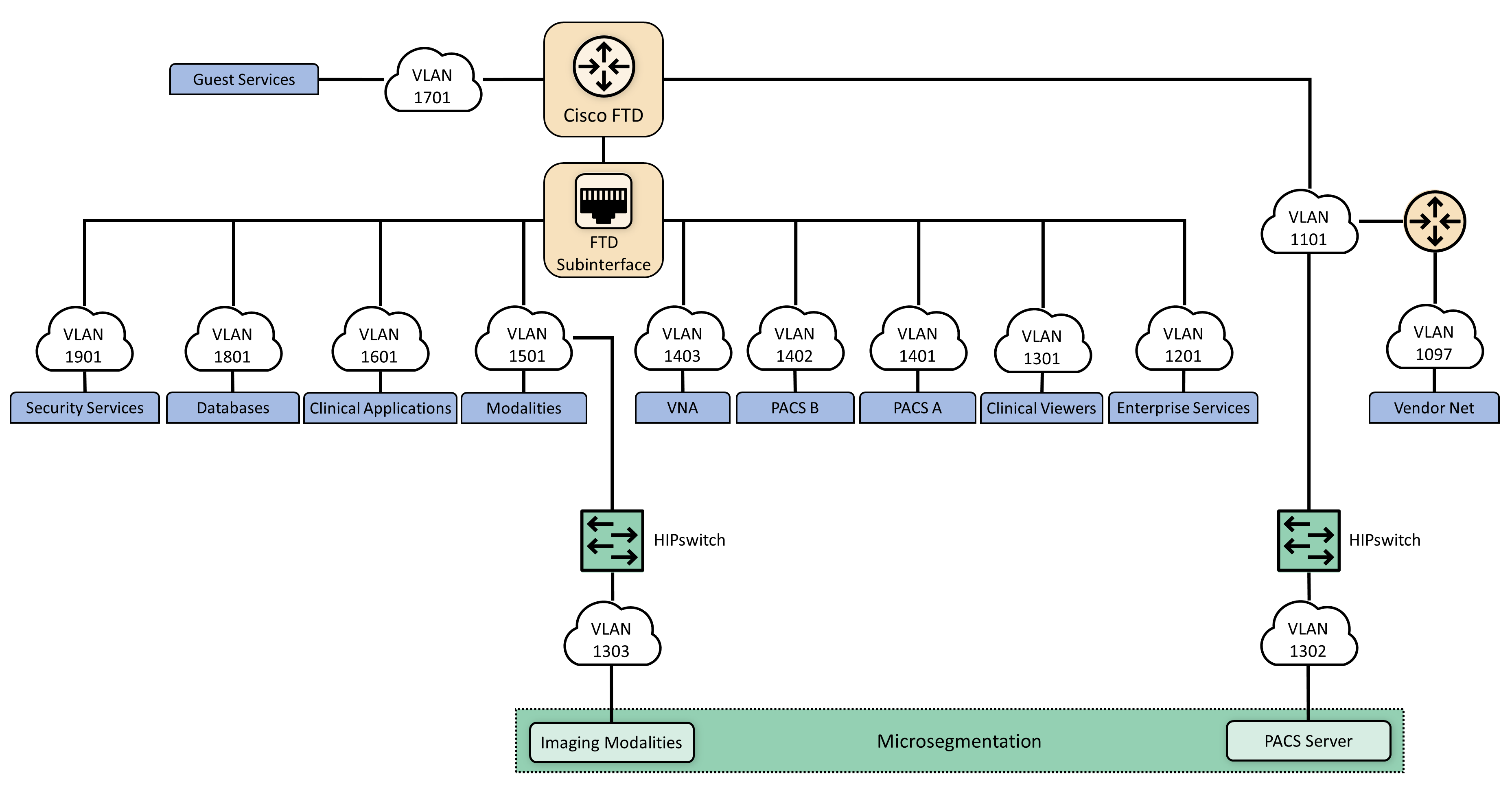
4.1.6.2 Firewall and Control Policies¶
This project used Cisco’s Firepower Next Generation Firewall (NGFW). The NGFW provides several features that combine features previously found in separate perimeter security products such as intrusion prevention systems, application firewalls, proxy servers, and network packet inspection tools. The NGFW allows integration of other tools to defend the network against malicious activity.
As network and application attacks become more advanced, network controls should be enhanced beyond stateful traffic filtering. NGFW goes beyond ports, protocols, and IP addresses, providing standard policy-based protection, while including more advanced tools such as intrusion prevention systems, application filtering, uniform resource locator (URL) filtering, and geo-location blocking. The PACS ecosystem faces a variety of threats from different sources, and a comprehensive approach to network security is vital. The lab implemented network zoning by using policy and configuration settings through Firepower. This allowed the project to implement network zoning and proactive network traffic filtering.
4.1.6.3 Microsegmentation¶
Microsegmentation uses software-defined networking (SDN) to create a virtual overlay network over the existing network infrastructure. Devices may be grouped based on usage, with developed policies that establish granular degrees of trust. This project implemented the SDN overlay using host identity protocol (HIP) over the existing network infrastructure and offers in-transit network encryption. This project used microsegmentation to establish network control for modalities. Modalities represent medical imaging devices. These endpoint devices may contain exploitable vulnerabilities and may not have practical means to mitigate compromise beyond network protection. While VLAN-defined network zoning may afford network protection, this guide implements microsegmentation for these medical devices to reduce VLAN management complexity and provide more robust network segregation for medical devices. A microsegmentation approach may offer a solution that requires less impact to network configuration while limiting adverse interaction with the modalities.
This practice guide implemented microsegmentation through Tempered Networks’ HIP solution that includes HIPswitches implementing HIP, as described in the Internet Engineering Task Force (IETF) request for comments 4423 [B27]. HIP provides a cryptographically defined host identifier bound to endpoints rather than IP addresses. Network traffic between HIP-enabled endpoints traverses a series of HIPswitches deployed in the lab network infrastructure, creating a cloaked network that operates on top of the physical network. The cloaked network uses advanced encryption standard (AES)-256 encryption to secure data in transit and uses secure hash algorithm (SHA)-256 to authenticate data packets from HIP-enabled endpoints [B27], [B28], [B29]. Figure 4‑6 below depicts the microsegmentation architecture deployed in the project’s test build.
Figure 4‑6 Microsegmentation Architecture
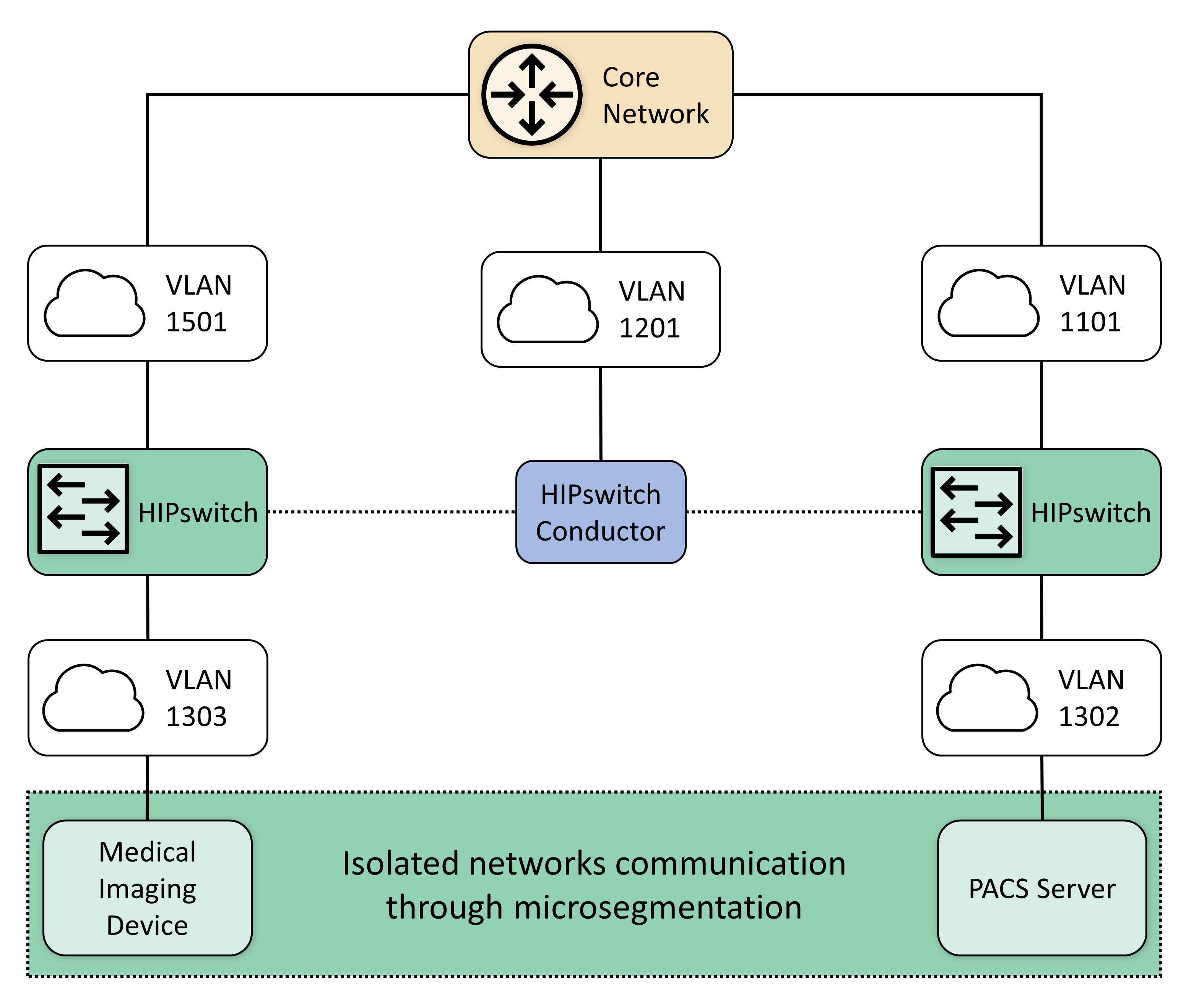
While VLAN segmentation can help reduce unwanted lateral movement within a network, it does not restrict lateral movement within that zone. For some devices and workloads, it may be necessary to isolate their operations and allow only a select few interactions with other devices. The project team determined that microsegmentation would be an appropriate control to protect medical imaging devices that may operate embedded operating systems or firmware where patch release cycles may be different from current commercial off-the-shelf operating systems. Microsegmentation provides this fine-grained approach to isolation and can be implemented within an existing network.
Within the PACS ecosystem, we identified an area where microsegmentation would improve operational security. This guide implements microsegmentation through a solution based on HIP. HIP uses cryptographic host identifiers rather than IP addresses to address and authenticate endpoints and to create secure tunnels. This guide uses this concept to abstract IP addressing away from the modalities, using identity-defined perimeters where endpoint devices are authenticated to HIPswitches and allow secure tunnel communications to other HIPswitches [B27].
For this practice guide’s architecture, it was important to secure this line of communication and ensure that appropriate defenses protect devices from potential threats. To accomplish this, the project established two identity-defined perimeters on two separate VLANs. This project then placed a modality behind one perimeter and a PACS behind the other. This project configured these perimeters to allow only authorized traffic between them, meaning the modality was allowed to communicate only with the PACS and vice versa. Additionally, the project encrypted all traffic between the two perimeters, ensuring the data were secure in-transit.
4.1.6.4 Anomalies and Events Detection (Behavioral Analytics)¶
Medical devices often operate within strict requirements and limited resources. This makes certain tasks like vulnerability assessment difficult to manage, as they often require obtrusive operations such as a host-installed agent. Network-based behavioral analytics can perform the same assessments, identifying suspicious operations without affecting medical device function or performance. Behavioral analytics is an automated feature that collects and analyzes network traffic flow and compares the results to a pre-established baseline to determine whether devices are operating abnormally.
For the PACS architecture, the project identified network flows, primarily among PACS, VNA, and modalities, where it is important to monitor for abnormal behavior. With a baseline established, the project can identify when endpoints attempt to conduct network operations outside their normal profile. With this information, we can verify and remediate the threat. The project implemented the Zingbox IoT Guardian solution.
4.1.6.5 Intrusion Detection and Prevention Systems¶
Components managed through an HDO’s IT operations team would implement control mechanisms to perform malware detection, vulnerability scanning, and remediation. This project involved several workstations (e.g., image viewing devices), as well as servers that may operate commercially available operating systems. This project deployed host-based agents, as appropriate, to permit the IT team to perform regular vulnerability scanning for those non-modality systems. This project implemented Symantec Endpoint Protection on image viewing workstations. Also, the project implemented the Cisco Firepower NGFW that included a network-based intrusion prevention mechanism [B30].
4.1.7 Endpoint Protection and Security¶
This practice guide implements endpoint protection and security through device hardening and configuration controls. Protected endpoints include both workstations and servers. This project used several workstations to represent clinical workstations and used medical image viewers as the means to connect to the PACS and VNA servers. The project deployed endpoint protection to servers by installing Symantec Endpoint Protection as the automated solution addressing vulnerability management requirements. The practice guide installed Tripwire Enterprise for configuration management on the servers.
Endpoints represent potential targets for malicious actors, and assuring appropriate control is critical to enterprise risk management. Automated tools that leverage endpoint-deployed agents that process policy may provide HDOs greater asset control and limit potential compromise.
4.1.8 Device Hardening and Configuration¶
This project deployed Tripwire Enterprise on server components (e.g., the Hyland Acuo server and the Philips IntelliSpace server) to address device hardening and configuration management.
This project deployed a host intrusion prevention system (HIPS) to protect servers performing critical functions in the HDO. The HIPS tool prevents the internals of an operating system from performing unintended or malicious activity. This mechanism can provide further protection from attackers attempting to compromise the system by preventing installation or execution of malicious software. This tool supports policy-based rules for monitoring file system changes of critical operating system application and system file directories. This allows the tool to monitor critical settings of the operating system, such as Windows registry keys. In our environment, we used these tools to ensure that new executables were not installed, thus reducing the attack surface of critical systems.
In conjunction with HIPS, a FIM system protects clinical servers in the reference architecture. This system monitors file system changes, looking for suspicious changes. The FIM system also evaluates policy compliance to ensure the critical servers comply with the HDO policies.
4.1.8.1 Malware Detection¶
An endpoint-based malware detection system, commonly referred to as anti-virus software, prevents, detects, and removes malicious software from systems. This function is critical to protecting the systems that healthcare professionals use to interact with the PACS, such as the imaging workstations. The anti-virus software implemented in our reference architecture analyzes suspicious behavior, performs firewall functions, and allows custom, policy-based enforcement. These added functions enhance the ability for HDOs to respond to the threat of malicious software on healthcare systems. This practice guide deployed the Symantec Endpoint Protection solution on workstations hosting our DICOM image viewers.
A network-based malware detection system, commonly referred to as an intrusion detection system (IDS), detects malicious activity over the network. In our reference architecture, the IDS interfaces directly with the manager of the endpoint-based malware detection system. This gives the IDS the ability to use data collected from the endpoint to better detect malicious activity on the network [B30].
4.1.9 Data Security¶
This project considered challenges associated with data loss and data alteration. A challenge noted while looking at the medical imaging ecosystem is the diversity of data types that may be prone to varying threat types, with compromise resulting in different adverse outcomes. This project examined data flows between the implemented components and identified a need to secure data in-transit and data at-rest.
4.1.9.1 Data Encryption (at-rest and in-transit)¶
Microsoft Azure provides cloud storage for this practice guide. Encrypted network sessions between the HDO and the cloud storage provider use TLS, Internet Protocol Security (IPSec) and Internet Key Exchange (IKE). Azure assigns a storage account to the HDO. Access to medical images stored in the cloud service requires storage account credentials. Azure enforces storage account access control using HTTPS with TLS, Perfect Forward Secrecy, and Rivest-Shamir-Adleman (RSA) cryptosystem 2048-bit encryption keys. Azure assures data-at-rest encryption using service-managed keys. Azure encrypts partitions or blocks of data using AES-256 bit keys [B31].
This practice guide recommends referring to NIST SP 1800-11, Data Integrity: Recovering from Ransomware and Other Destructive Events [B32], for measures that address backup and recovery. This project implemented PACS and VNA solutions on Windows servers, and this practice guide recommends implementing secure server message block best practices, e.g., as provided by Department of Homeland Security Cybersecurity and Infrastructure Security Agency [B33].
Examining the communications traffic flow, the project team determined that relevant data are sensitive in nature. Medical images and accompanying clinical notes and diagnoses are PHI and have requirements that align with confidentiality, integrity, and availability.
This project authenticates communications from the modalities to the PACS and VNA using HIP, which also provides network encryption. HIP employs AES-256 encryption [B27], [B28], [B29] to secure network sessions. By deploying HIP, this project sought to defend against network-borne attacks, including man-in-the-middle attacks where data may be altered in transit.
When multiple PACS data were aggregated into the VNA, the project enabled TLS tunneling. TLS uses DigiCert TLS certificates to implement AES-256 network encryption [B28], [B29], [B35].
Image viewers, as well as mobile devices using Hyland’s PACSgear scanning tool, use https/TLS when connecting and communicating to the VNA or PACS respectively [B35].
4.1.10 Remote Access¶
Both healthcare and IT systems require access by vendor-support technicians for remote configuration, maintenance, patching, and updates to software and firmware. The project used a remote access network segment to provide these external privileged users with privileged access to these components that reside within our reference architecture. A virtual private network (VPN) solution provides a secure way in which an organization can extend its private network across the internet, ensuring that only properly authenticated users can access their organization’s private network. This project configured and managed the NCCoE VPN in our environment using vendor-recommended practices [B36]. This project implemented TDi ConsoleWorks as a remote access mechanism into the infrastructure.
To further secure access to remote resources, the team implemented a privileged access management (PAM) solution [B24]. The PAM solution provides two-factor authentication (2FA), fine-grained access control, and monitoring user access to remote resources. 2FA is provided via domain-based username and password and an application-based security token available on the user’s mobile device. This project implemented 2FA in the test build using Symantec Validation and ID Protection (VIP) solution. The project integrated Symantec VIP into the ConsoleWorks authentication mechanism to enforce username password plus onetime passcode to make up the two factors.
4.2 Final Architecture¶
The target architecture, depicted in Figure 4‑7, demonstrates control measures such as microsegmentation and network segmentation as described by this practice guide. The architecture depicts network zones using VLANs, with the modalities zone implemented using microsegmentation. The target architecture also includes using cloud storage for long-term archiving and serves to enhance resiliency and recoverability should the HDO be subject to an adverse event.
Figure 4‑7 PACS Final Architecture
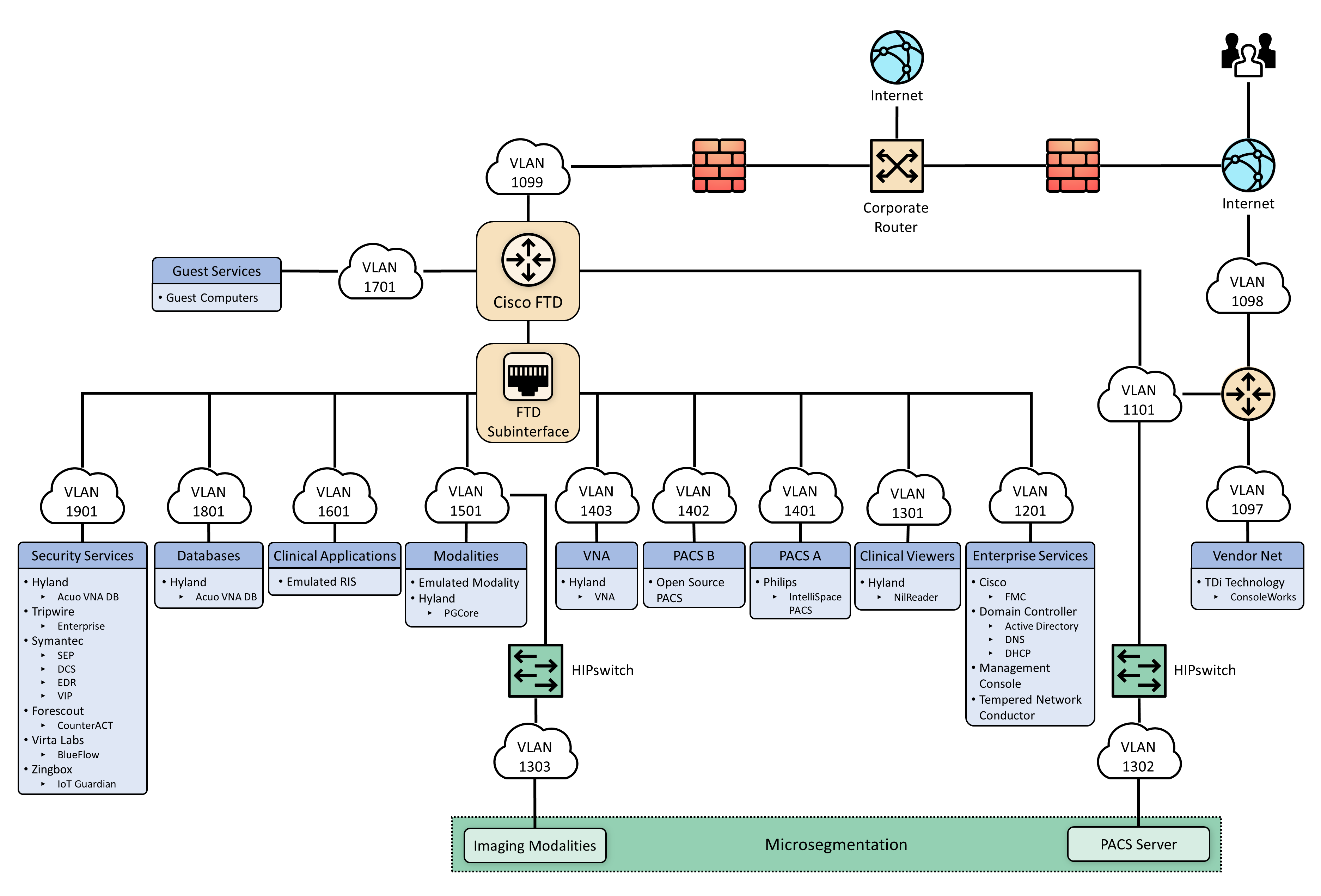
5 Security Characteristic Analysis¶
The purpose of the security characteristic analysis is to understand the extent to which the project meets its objective of demonstrating the security capabilities described in the reference architecture in Section 4. This evaluation focuses on the security of the reference design itself. In addition, it seeks to understand the security benefits and drawbacks of the example solution.
5.1 Assumptions and Limitations¶
The security characteristic analysis has the following limitations:
It is neither a comprehensive test of all security components nor a red-team exercise.
It cannot identify all weaknesses.
It does not include the lab infrastructure. It is assumed that devices are hardened. Testing these devices would reveal only weaknesses in implementation that would not be relevant to those adopting this reference architecture.
5.2 Scenarios and Findings¶
One aspect of our security evaluation involved assessing how well the reference design addresses the security characteristics that it was intended to support. The Cybersecurity Framework subcategories were used to provide structure to the security assessment by consulting the specific sections of each standard cited in reference to a subcategory. The cited sections provide validation points that the example solution would be expected to exhibit. Using the Cybersecurity Framework subcategories as a basis for organizing our analysis allowed us to systematically consider how well the reference design supports the intended security characteristics.
5.3 Analysis of the Reference Design’s Support for Cybersecurity Framework Subcategories¶
Using the NIST Cybersecurity Framework subcategories to organize our analysis also provided additional confidence that the reference design addresses our use case security objectives. The remainder of this subsection discusses how the reference design supports each of the identified Cybersecurity Framework subcategories [B8].
Table 3‑5 lists the reference design functions and the security characteristics, along with products that we used to instantiate each capability. The focus of the security evaluation is not on these specific products but on the Cybersecurity Framework subcategories. There may be other commercially available products that meet the objectives found in the NIST Cybersecurity Framework. Practitioners may substitute other products that provide comparable security control within the reference design.
5.3.1 Asset Management (ID.AM)¶
This practice guide considered ID.AM-1, ID.AM-2, ID.AM-4, and ID.AM-5 to address asset management.
The practice guide implemented ID.AM-1 using Virta Labs BlueFlow to address modality asset management. Establishing an asset inventory is a fundamental component in determining appropriate controls for the environment. The ID.AM-1 Subcategory specifies, “[p]hysical devices and systems within the organization are inventoried,” and ID.AM-2 specifies, “[s]oftware platforms and applications within the organization are inventoried.” This practice guide groups the ID.AM-1 and ID.AM-2 subcategories together. The practice guide identifies tools that align with objectives defined by one or more of the Cybersecurity Framework subcategories. Physical devices include workstation, server, and storage components, whereas software assets include those applications that run on the physical components.
The practice guide emulates HDOs in that HDOs often have separate biomedical engineering teams, distinct from central IT operations. The implication is that IT general assets and medical devices may have distinct asset-tracking mechanisms. BlueFlow captures inventory, configuration, and patch management information.
ID.AM-4 specifies, “[e]xternal information systems are catalogued.” The Clearwater Information Risk Management Analysis tool would track cloud services as part of the IT asset inventory.
Medical device asset tracking may be distinct from what is maintained in a general IT asset database. For this project, the team maintained simulated medical imaging devices and implemented the Virta Labs BlueFlow tool for asset tracking and configuration management.
ID.AM-5 specifies, “[r]esources (e.g., hardware, devices, data, time, personnel, and software) are prioritized based on their classification, criticality, and business value.” To address ID.AM-5, this project implemented solutions to identify communication and data flows between IT and biomedical engineering assets. The project implemented the Zingbox IoT Guardian and Cisco Stealthwatch solution to analyze NetFlow traffic across the laboratory infrastructure. In capturing NetFlow patterns, the project provided two primary benefits: 1) a baseline of communication flows between medical imaging devices, workstations, and PACS/VNA systems, and 2) an ability to determine when communication patterns were anomalous.
5.3.2 Risk Assessment (ID.RA)¶
This project selected ID.RA-1 and ID.RA-5 to address the Risk Assessment category. ID.RA-1 specifies, “[a]sset vulnerabilities are identified and documented,” and ID.RA-5 specifies “[t]hreats, vulnerabilities, likelihoods, and impacts are used to determine risk.” The project identified and deployed tools to address these control requirements.
This project used Symantec’s Endpoint Protection solution to address threats to image viewer workstations. The project used Tripwire Enterprise to monitor server assets. This practice guide implemented Virta Labs BlueFlow to manage and assess medical imaging devices. The project also used Zingbox IoT Guardian to perform NetFlow analysis. Practitioners may use information from these tools when needed to determine the risk profile of the HDO environment.
5.3.3 Identity Management and Access Control (PR.AC)¶
To implement identity management and access control, the project team focused on PR.AC-1, PR.AC-4, and PR.AC-7 Subcategories. PR.AC-1 specifies, “[i]dentities and credentials are issued, managed, verified, revoked, and audited for authorized devices, users and processes.” PR.AC-4 specifies, “[a]ccess permissions and authorizations are managed, incorporating the principles of least privilege and separation of duties.” PR-AC7 specifies, “[u]sers, devices, and other assets are authenticated commensurate with the risk of the transaction.”
5.3.3.1 Identity Management¶
The project used Microsoft Active Directory to provision human user access to workstations and systems. This project implemented the Symantec VIP. The Symantec VIP tool gave the project multifactor authentication (MFA) capability. MFA enhances non-repudiation within the authentication process. MFA provides additional factors, apart from a password, that assures that when an individual presents a credential, they are doing so appropriately. For further information on MFA, practitioners may consult with NIST 800-63-3 Digital Identity Guidelines [B34]. Table 5‑1 describes how the project managed different user types and describes some general characteristics of that user type.
Table 5‑1 Identity Management Characteristics
User Type |
Identity |
Tool |
Characteristics |
|---|---|---|---|
Human Users |
Active Directory |
Active Directory |
Human user authentication method dependent on interaction type |
Medical Imaging Devices |
Host Identifier |
Tempered Networks IDN |
Imaging devices abstracted from the production network over a cloaked network implementing HIP |
System to System |
Certificate |
DigiCert Managed PKI |
Automated interactions between systems authenticated |
HDO to Cloud Storage Provider |
Access Keys; Azure Active Directory |
Microsoft Azure |
Authentication to cloud storage provider is provided using access keys. |
This project emulated medical imaging devices. They authenticate using HIP, implemented in Tempered Networks’ microsegmentation capability. The Tempered Networks solution, IDN, uses the HIP, which incorporates a key exchange capability between endpoint devices and gateways, or HIPswitches.
The practice guide included a document scan utility installed on a mobile device. To enable device authentication in this case, the project used DigiCert Managed PKI, providing certificate-based authentication.
The project augmented device authorization management by limiting PACS accessibility based on workstation zone provisioning. The practice guide installed Symantec VIP to enable multifactor authentication for certain devices. The practice guide secured network sessions with TLS applying DigiCert-issued certificates [B35].
5.3.3.2 Access Control¶
To implement PR.AC-4, this project used role-based access control (RBAC) features built into the PACS and the VNA systems. Philips IntelliSpace and Hyland Acuo VNA implement RBAC, allowing least privilege access enforcement.
This project also took advantage of the network zoning concept and limited access based on firewall policies that restrict traffic between different zones. For example, the project limited image viewer workstation network traffic to the PACS and VNA for image retrieval and interaction to specified network zones.
Administrative functions are restricted and are performed through TDi ConsoleWorks sessions that enforce multifactor authentication.
The project implemented PR.AC-3 using TDi Technologies ConsoleWorks to provide remote access to the lab network. The ConsoleWorks environment provided a solution for vendor remote access as well as general user remote VPN, including access by third-party medical imaging services that may need access to patient images [B36].
To implement PR.AC-5, the project made significant use of network segmentation through VLANs implemented with Cisco Firepower NGFW and through microsegmentation implemented using Tempered Networks IDN. Identity Defined Networking (IDN) implements an SDN that this project used to secure communications between the simulated medical imaging devices and the PACS/VNA environment.
The project managed access to Azure resources in two ways. Management plane functions, which include creation, modification, and deletion of cloud resources, are protected using Azure AD and RBAC. Best practices for management plane access include least privilege, MFA, and secure administrative workstations. Access to services inside Azure resources is referred to as data plane functions. Authentication at this layer occurs in multiple ways. For storage accounts, authentication occurs using access keys and policies. The interaction between storage accounts and the Key Vault for encryption key retrieval uses Azure Active Directory.
5.3.4 Data Security (PR.DS)¶
For this project, the team identified PR.DS-1, “[d]ata-at-rest is protected;” PR.DS-2, “[d]ata-in-transit is protected;” PR.DS-6,“[i]ntegrity checking mechanisms are used to verify software, firmware, and information integrity” subcategories to address data security.
This practice guide implements Microsoft Azure for cloud storage. The HDO environment establishes a TLS tunnel using digital certificates that Azure manages. The TLS tunnel assures data-in-transit protection. Azure also implements AES-256 encryption for data-at-rest.
The project installed Symantec Encryption Platform to protect workstations in this practice guide.
This project implemented TLS and HIP to assure data in-transit protection. Image viewing workstations connecting to the PACS/VNA environments use TLS encryption to ensure data-in-transit protection [B27], [B28], [B35]. This project also implements microsegmentation with Tempered Networks and ensures data-in-transit protection by HIP-managed encryption between emulated medical imaging devices and the PACS/VNA environment.
The practice guide uses Tripwire Enterprise and Symantec DCS:SA to provide integrity monitoring of system software files.
PR.DS-6 includes a control objective to additionally manage firmware; however, the lab used emulated medical imaging devices for its modalities, operating as virtual machines. These emulated devices did not include a firmware component.
5.3.5 Information Protection and Procedures (PR.IP)¶
This project selected PR.IP-1, PR.IP-3, and PR.IP-4 to implement the Information Protection and Procedures Category. PR.IP-1 specifies, “[a] baseline configuration of information technology/industrial control systems is created and maintained incorporating security principles (e.g., concept of least functionality).” PR.IP-3 specifies, “[c]onfiguration change control processes are in place;” and PR.IP-4 specifies, “[b]ackups of information are conducted, maintained, and tested.”
Servers supporting the PACS and VNA systems were built using guidance received from Philips and Hyland, respectively. This project regarded these configurations as baseline configurations and determined them to be based on application functionality requirements. Tripwire Enterprise monitors modifications.
Virta Labs BlueFlow manages medical imaging device configurations. The practice guide emulated medical imaging devices deployed in the lab. Emulated medical devices did not involve firmware.
5.3.6 Protective Technology (PR.PT)¶
To implement Protective Technology, this project selected PR.PT-1, PR.PT-3, and PR.PT-4. PR.PT-1 specifies, “[a]udit/log records are determined, documented, implemented, and reviewed in accordance with policy.” PR.PT-3 specifies, “[t]he principle of least functionality is incorporated by configuring systems to provide only essential capabilities;” and PR.PT-4 specifies, “[c]ommunications and control networks are protected.”
To address PR.PT-1, the Hyland Acuo VNA, Hyland NilRead Enterprise, Hyland PACSgear, Philips Enterprise Imaging IntelliSpace PACS, and Philips Enterprise Imaging Universal Data Manager components provided the capability to create audit log records.
The practice guide implemented Zingbox IoT Guardian to assure regular network traffic monitoring. The tool aggregated NetFlow traffic across the lab environment and performed behavioral analytics. HDOs should also consider using a security incident event management (SIEM) system that would aggregate logs from different operating systems, applications, and component types. SIEM tools often can support scripts that may trigger alerting to incident response teams.
To address PR.PT-3, this project implemented operating systems that were configured with the minimum functionality necessary to support PACS and VNA operations, based on guidance from Hyland and Philips, respectively. These collaborators provided configuration recommendations that were applied as baseline settings. The practice guide then used Tripwire Enterprise to monitor this baseline.
This project implements PR.PT-4 through constructing network zones with VLANs and using the Tempered Networks microsegmentation solution. The project used VLANs to establish a base set of network zones, and the Tempered Networks IDN created a means to control network traffic between the simulated medical imaging devices and the PACS/VNA leveraging the HIP, which protects data on networks via data encryption.
The project used the Cisco Firepower NGFW to protect the infrastructure from malicious activity.
TLS and IPsec tunneling protected external connections where appropriate [B35], [B36].
5.3.7 Anomalies and Events (DE.AE) and Security Continuous Monitoring (DE.CM)¶
This project grouped together the Functions DE.AE Anomalies and Events and DE.CM Security Continuous Monitoring. The project then selected DE.AE-1, DE.AE-2, DE.AE-3, DE.AE-5, DE.CM-1, DE.CM-3, and DE.CM-7 to address these control areas.
Selected controls for DE.AE Anomalies and Events include DE.AE-1: “[a] baseline of network operations and expected data flows for users and systems is established and managed”; DE.AE-2: “[d]etected events are analyzed to understand attack targets and methods”; DE.AE-3: “[e]vent data are collected and correlated from multiple sources and sensors”; and DE.AE-5: “[i]ncident alert thresholds are established.” This project implemented Zingbox IoT Guardian and Cisco Stealthwatch to achieve these objectives through implementing behavioral analytics. The practice guide configured Zingbox for continuous monitoring by directing NetFlow traffic to its cloud-hosted back end where it performed analysis. The practice guide configured Stealthwatch for monitoring and analysis on-premise.
DE.CM-1 specifies, “[t]he network is monitored to detect potential cybersecurity events”; DE.CM-3: “[p]ersonnel activity is monitored to detect potential cybersecurity events”; and DE.CM-7: “[m]onitoring for unauthorized personnel, connections, devices, and software is performed.” The project addresses DE.CM-1 through the Zingbox and Stealthwatch implementations. The solutions perform network monitoring and cybersecurity event detection by analyzing NetFlow traffic. The project performed additional network monitoring using the Cisco Firepower Next Generation Firewall deployment.
DE.CM-4 specifies, “[m]alicious code is detected”; and DE.CM-7 specifies, “[m]onitoring for unauthorized personnel, connection, devices, and software is performed.” This project implemented Symantec Endpoint Protection to address DE.CM-4 and DE.CM-7. The practice guide implemented intrusion prevention with the Cisco Firepower Next Generation Firewall. The practice guide deployed Symantec Endpoint Protection on workstations, including image viewer workstations.
5.4 Security Analysis Summary¶
The practice guide’s reference design implementation of security surrounding the PACS/VNA helps reduce risk from the PACS/VNA, even when practitioners identify vulnerabilities in a PACS or VNA. The key feature is the multilayered security capabilities defined in Section 4.1.3. This practice guide followed our collaborative partners’ recommended security practices to harden devices and systems; monitor traffic; limit access to only authorized users, devices, and systems; and ensure data security across the ecosystem. Any organization following this guide must conduct its own analysis of how to employ the elements discussed here, in its own environment. It is essential that organizations follow security best practices to address potential vulnerabilities and to minimize any risk to the operational network.
6 Functional Evaluation¶
We conducted a functional evaluation of our example implementation to verify that several common provisioning functions used in our laboratory test worked as expected. We also needed to ensure that the example solution would not alter normal PACS and VNA functions.
In developing a test plan, this project identified implemented cybersecurity controls and identified a method to demonstrate control functionality. Also, this project identified five IHE use case scenarios that implemented multiple cybersecurity controls to augment business process functionality. The identified scenarios found in Section 3.4.3 served as the basis of a functional test plan to demonstrate overall security control efficacy.
Section 6.1 describes the format and components of the functional test cases. Each functional test case is designed to assess the security capabilities of the example implementation to perform the functions listed in Section 4.1.3.
6.1 PACS Functional Test Plan¶
Each test case consists of multiple fields that collectively identify the goal of the test, the specifics required to implement the test, and how to assess the results of the test. Table 6‑1 describes each field in the test case.
Table 6‑1 Test Case Fields
Test Case Field |
Description |
|---|---|
Parent Requirement |
Identifies the top-level requirement or the series of top-level requirements leading to the testable requirement |
Testable Requirement |
Drives the definition of the remainder of the test case fields and specifies the capability to be evaluated |
Associated Cybersecurity Framework Subcategories |
Lists the NIST Cybersecurity Framework Subcategories addressed by the test case |
Description |
Describes the objective of the test case |
Associated Test Cases |
In some instances, a test case may be based on the outcome of (an)other test case(s). For example, analysis-based test cases produce a result that is verifiable through various means (e.g., log entries, reports, and alerts). |
Preconditions |
The starting state of the test case. Preconditions indicate various starting-state items, such as a specific capability configuration required or specific protocol and content. |
Procedure |
The step-by-step actions required to implement the test case. A procedure may consist of a single sequence of steps or multiple sequences of steps (with delineation) to indicate variations in the test procedure. |
Expected Results |
The expected results for each variation in the test procedure |
Actual Results |
The observed results |
6.1.1 PACS Functional Evaluation Requirements¶
Table 6‑2 identifies the PACS functional evaluation requirements addressed in the test plan and associated test cases. The evaluations are aligned with the basic architecture design and capability requirements from Section 4, Architecture.
Table 6‑2 Functional Evaluation Requirements
Capability Requirement (CR) ID |
Parent Requirement |
Subrequirement |
Test Case |
|---|---|---|---|
CR-1 |
Business workflows that support image acquisition and transfer to archival (e.g., PACS and VNA) are performed. |
Sample Radiology Practice Workflows |
PACS-1
PACS-11
|
CR-2 |
Asset and Inventory Management |
PACS-2 |
|
CR-3 |
Enterprise Domain and Identity Management–Access Control |
||
CR-3.a |
Privileged Access Management |
PACS-3
PACS-10
|
|
CR-3.b |
User Authentication |
PACS-3
PACS-4
PACS-5
PACS-10
|
|
CR-3.c |
Device and System Authentication |
PACS-3
PACS-4
PACS-5
PACS-11
|
|
CR-3.d |
Data Access Control |
PACS-3
PACS-5
|
|
CR-4 |
Network Control and Security |
||
CR-4.a |
Network Segmentation and VLANs |
PACS-7 |
|
CR-4.b |
Firewall and Control Policies |
PACS-7 |
|
CR-4.c |
Microsegmentation |
PACS-4 |
|
CR-4.d |
Anomalies and Events Detection (Behavioral Analytics) |
PACS-8 |
|
CR-4.e |
Intrusion Detection and Prevention |
PACS-9 |
|
CR-5 |
Endpoint Protection and Security |
||
CR-5.a |
Device Hardening and Configuration |
PACS-9 |
|
CR-5.b |
Malware Detection and Prevention |
PACS-9 |
|
CR-6 |
Data Security |
||
CR-6.a |
In-Transit Encryption |
PACS-4
PACS-5
PACS-12
|
|
CR-7 |
Remote Access |
Remote Access |
PACS-10 |
6.1.2 Test Case: PACS-1¶
Parent Requirement |
(CR-1) Business workflows that support image acquisition and transfer to archival (e.g., PACS and VNA) are performed. |
Testable Requirement |
(CR-1) Sample Radiology Practice Workflows |
Description |
Demonstrate that the installed PACS can be used to acquire images from a simulated modality, store those images based on department, and view those images by using a DICOM viewer. |
Associated Test Case |
N/A |
Associated Cybersecurity Framework Subcategories |
N/A |
Preconditions |
|
Procedure |
|
Expected Results |
Note: If you need to repeat the same procedure using the same samples, clear the stored image from the Philips PACS. The cleared image stored in the Default folder will be moved to the Exceptions Lookup folder. Clear the image from the Exceptions Lookup folder as well. |
Actual Results |
The implemented PACS environment successfully scheduled images by using the RIS, sent and stored the images in the PACS using the modality, and viewed the stored images using a web client. |
6.1.3 Test Case: PACS-2¶
Parent Requirement |
(CR-2) Asset and Inventory Management |
Testable Requirement |
(CR-2) Asset and Inventory Management |
Description |
Demonstrate how to identify and manage medical assets. |
Associated Test Case |
N/A |
Associated Cybersecurity Framework Subcategories |
ID.AM-1, ID.AM-2, ID.AM-4, ID.AM-5, ID.RA-1, ID.RA-5, PR.IP-1 |
Preconditions |
|
Procedure |
|
Expected Results |
|
Actual Results |
More than 20 new devices were discovered within the PACS VLANs. These new devices were placed automatically into predefined network segments, and devices that did not fit into a predefined network segment were placed into an Other Assets category. The fingerprint tool populated descriptive information for several discovered devices while all other necessary information was filled in manually. |
6.1.4 Test Case: PACS-3¶
Parent Requirement |
(CR-3) Enterprise Domain and Identity Management–Access Control |
Testable Requirement |
(CR-3.a) Privileged Access Management, (CR-3.b) User Authentication, (CR-3.c) Device and System Authentication, (CR-3.d) Data Access Control |
Description |
Demonstrate the capability authentication to the PACS application by using enterprise active directory (AD). |
Associated Test Case |
N/A |
Associated Cybersecurity Framework Subcategories |
PR.AC-1, PR.AC-4, PR.AC-7 |
Preconditions |
|
Procedure |
|
Expected Results |
|
Actual Results |
A PACS-user, who is in the AD, was used to test the access setup. After entering the username and the correct password to the Philips IntelliSpace PACS Enterprise login page by using the AD PACS as the authentication source, the login was successful. The PACS-user account was validated to assure that appropriate access control settings were applied. PACS-user authentication was further tested, first by entering an incorrect password and next by incorrectly spelling the username. These attempts failed. |
6.1.5 Test Case: PACS-4¶
Parent Requirement |
(CR-4) Network Control and Security (CR-6) Data Security |
Testable Requirement |
(CR-4.c) Microsegmentation, (CR-6.a) In-Transit Encryption |
Description |
Demonstrate secure transfer of medical images from modalities to archive systems by using microsegmentation. |
Associated Test Case |
PACS-3 |
Associated Cybersecurity Framework Subcategories |
PR.DS-2, PR.PT-1, PR.PT-3, PR.PT-4 |
Preconditions |
|
Procedure |
To schedule radiology patient studies with the DVTk Modality Emulator
To store patient studies on the Philips PACS server by using DVTk Modality Emulator
To verify that data are encrypted between the modality and the PACS
|
Expected Results |
|
Actual Results |
The RIS, Modality, and the PACS succeeded in establishing DICOM connections after microsegmentation was implemented. Data being transferred from Modality to the PACS was encrypted through the secured connection. |
6.1.6 Test Case: PACS-5¶
Parent Requirement |
(CR-3) Enterprise Domain and Identity Management–Access Control (CR-6) Data Security |
Testable Requirement |
(CR-3.b) User Authentication, (CR-3.c) Device and System Authentication, (CR-3.d) Data Access Control, (CR-6.a) In-Transit Encryption |
Description |
Show how clinical departments have access to only their department’s medical images and show that an encrypted connection is used when clinical departments are accessing medical images. |
Associated Test Case |
PACS-3 |
Associated Cybersecurity Framework Subcategories |
PR.AC-1, PR.AC-4, PR.AC-7, PR.DS-2, PR.PT-1, PR.PT-3, PR.PT-4 |
Preconditions |
|
Procedure |
To transfer patient studies from the Philips PACS server to the radiology user group on the Hyland VNA server
To confirm that Hyland VNA user accounts can access only approved departments
|
Expected Results |
|
Actual Results |
PACS was able to securely transfer patient studies by using TLS encryption to the radiology group on the archiving system. User accounts with access to view radiology patient studies were able to access only studies linked to the radiology department. |
6.1.7 Test Case: PACS-6¶
Parent Requirement |
(CR-3) Enterprise Domain and Identity Management–Access Control (CR-6) Data Security |
Testable Requirement |
(CR-3.b) User Authentication, (CR-3.c) Device and System Authentication, (CR-6.a) In-Transit Encryption |
Description |
Show how to securely review archived medical images. |
Associated Test Case |
PACS-3 |
Associated Cybersecurity Framework Subcategories |
PR.AC-1, PR.AC-4, PR.AC-7, PR.DS-2, PR.PT-1, PR.PT-3, PR.PT-4 |
Preconditions |
|
Procedure |
To authenticate as a radiology user and securely view patient studies for radiology department on the VNA
To evaluate encrypted data transfers from Hyland VNA to Hyland NilRead Viewer
|
Expected Results |
|
Actual Results |
Web viewer securely connected to the archiving server and transmitted patient images to a client computer over https. |
6.1.8 Test Case: PACS-7¶
Parent Requirement |
(CR-4) Network Control and Security |
Testable Requirement |
(CR-4.a) Network Segmentation and VLANs, (CR-4.b) Firewall, and Control Policies |
Description |
Demonstrate network segmentation and routing between VLANs within the PACS architecture by restricting guest network access. |
Associated Test Case |
N/A |
Associated Cybersecurity Framework Subcategories |
PR.AC-5, PR.PT-1, PR.PT-3, PR.PT-4 |
Preconditions |
|
Procedure |
To test that DHCP services are available for Guest network
To test that DNS services are available for Guest network
To test that traffic from Guest network to internal VLANs is blocked
To test that only web traffic from Guest network to the WAN is allowed
|
Expected Results |
|
Actual Results |
Upon booting up for the first time, the Windows computer on the Guest network was allocated an IPv4 address within the DHCP scope address pool and provisioned a DNS server address and was successfully able to resolve the IP address of a provided URL. The computer was not able to communicate with other devices in the internal PACS VLANs (192.168.140.131 and 192.168.130.120) using different network protocols (https and internet control message protocol) but was able to communicate with external web servers through a web browser using http and https. |
6.1.9 Test Case: PACS-8¶
Parent Requirement |
(CR-4) Network Control and Security |
Testable Requirement |
(CR-4.d) Anomalies and Events Detection (Behavioral Analytics) |
Description |
Demonstrate the capability to detect abnormal network traffic across the PACS architecture. |
Associated Test Case |
PACS-7 |
Associated Cybersecurity Framework Subcategories |
DE.AE-1, DE.AE-2, DE.AE-3, DE.AE-5, DE.CM-1, DE.CM-3, and DE.CM-7 |
Preconditions |
|
Procedure |
|
Expected Results |
|
Actual Results |
Zingbox identified BlueFlow’s IP scan as suspicious activity and created a security alert. Zingbox also created a security alert the second time a BlueFlow IP scan was run but stopped creating alerts for subsequent IP scans from the BlueFlow device. While the BlueFlow scan was approved and not malicious, this type of scanning can be performed by malicious devices attempting to discover devices on the network. |
6.1.10 Test Case: PACS-9¶
Parent Requirement |
(CR-4) Network Control and Security (CR-5) Endpoint Protection and Security |
Testable Requirement |
(CR-4.e) Intrusion Detection and Prevention, (CR-5.a) Device Hardening and Configuration, (CR-5.b) Malware Detection and Prevention |
Description |
Demonstrate the capability to detect threats affecting PACS servers and related end points. This test also demonstrates an intrusion detection capability. |
Associated Test Case |
N/A |
Associated Cybersecurity Framework Subcategories |
DE.CM-1, DE.CM-4, PR.PT-1, PR.PT-3, PR.PT-4 |
Preconditions |
|
Procedure |
To verify that the endpoint agent is connected to the SEP management server
To verify that the endpoint receives the current policy updates
To verify that the proper protections are enforced on the endpoint
To add a System Lockdown policy to prevent unwanted applications from running
To verify that the virus and spyware protection policy works
|
Expected Results |
|
Actual Results |
Prior to the lockdown policy enforcement, the 7zFM.exe file and 7zFM file manager console were able to run on the end point. After the lockdown policy enforcement, the 7zFM.exe file was not able to run, and a warning message appeared stating, “Windows cannot access the specified device, path, or file. You may not have the appropriate permissions to access the item.” When accessing the malware test file, the following message appeared: “Symantec Endpoint Protection [SID:24461] Diagnostic: EICAR Standard Anti-Virus Test File detected, Symantec Service Framework.” |
6.1.11 Test Case: PACS-10¶
Parent Requirement |
(CR-3) Enterprise Domain and Identity Management–Access Control (CR-7) Remote Access |
Testable Requirement |
(CR-3.a) Privileged Access Management, (CR-3.b) User Authentication |
Description |
Demonstrate the capability to provide controlled remote access to PACS using two-factor authentication. |
Associated Test Case |
PACS-3 |
Associated Cybersecurity Framework Subcategories |
PR.AC-3 |
Preconditions |
|
Procedure |
To verify that username/password are not sufficient to log in
To verify the two-factor authentication using username/password with a VIP token
To verify that the user can access only the granted resources
|
Expected Results |
|
Actual Results |
Using a pre-created Hyland user as an example, the first attempt to log in to the TDi console with only a username and password failed. The second attempt to log in, this time with a 2FA token, was successful. From the dashboard, the Graphical View menu was opened, and only approved graphical connections that were visible to the Hyland user (e.g., Hyland VNA, Hyland Database). The user was able to connect to these remote servers and authenticate with a Hyland service account. |
6.1.12 Test Case: PACS-11¶
Parent Requirement |
(CR-1) Business workflows that support image archiving and retrieving from archival (e.g., PACS and VNA) are performed. (CR-3) Enterprise Domain and Identity Management–Access Control |
Testable Requirement |
(CR-1) Sample Radiology Practice Workflows, (CR-3.c) Device and System Authentication |
Description |
Demonstrate that the installed PACS and the VNA system can connect to a dedicated remote cloud storage server to archive patient images. |
Associated Test Case |
PACS-1 |
Associated Cybersecurity Framework Subcategories |
PR.AC-1, PR.AC-7 |
Preconditions |
|
Procedure |
To identify when images should be archived in the Azure cloud storage for testing purposes
To identify how long images should stay in the cache for testing purposes
To store images in Microsoft Azure Cloud Storage
To retrieve images stored in Microsoft Azure Cloud Storage
To retrieve images stored in VNA Cache
|
Expected Results |
|
Actual Results |
Microsoft Azure successfully received and stored a patient study in the dedicated storage blob. Users were able to retrieve the study stored in the cloud instance and in the VNA’s cache. |
6.1.13 Test Case: PACS-12¶
Parent Requirement |
(CR-6) Data Security |
Testable Requirement |
(CR-6.a) In-Transit Encryption |
Description |
Demonstrate secure transfer of medical images from VNA to Remote Cloud Storage using TLS. |
Associated Test Case |
N/A |
Associated Cybersecurity Framework Subcategories |
PR.DS-2, PR.PT-4 |
Preconditions |
|
Procedure |
|
Expected Results |
|
Actual Results |
VNA was able to securely transfer patient studies by using TLS encryption to the Microsoft Azure storage blob. |
7 Future Build Considerations¶
The healthcare landscape continues to evolve as industry develops and adopts new technologies and services. In the medical imaging ecosystem, one such new development is the use of cloud-based enterprise imaging solutions. These solutions can help ensure data security in the event of a disaster, increase patient access to their own data, and improve efficiencies within the HDO. However, cloud-based enterprise imaging solutions may introduce new cybersecurity risks. An update to this practice guide could review the implications and potentially improve the cybersecurity of cloud-based enterprise imaging solutions.