NIST SPECIAL PUBLICATION 1800-23
Energy Sector Asset Management
For Electric Utilities, Oil & Gas Industry
Volume B:
Approach, Architecture, and Security Characteristics
James McCarthy
Glen Joy
National Cybersecurity Center of Excellence
Information Technology Laboratory
Lauren Acierto
Jason Kuruvilla
Titilayo Ogunyale
Nikolas Urlaub
John Wiltberger
Devin Wynne
The MITRE Corporation
McLean, Virginia
May 2020
Final
This publication is available free of charge from: https://doi.org/10.6028/NIST.SP.1800-23
The first draft of this publication is available free of charge from: https://www.nccoe.nist.gov/library/energy-sector-asset-management-nist-sp-1800-23-practice-guide

DISCLAIMER
Certain commercial entities, equipment, products, or materials may be identified by name or company logo or other insignia in order to acknowledge their participation in this collaboration or to describe an experimental procedure or concept adequately. Such identification is not intended to imply special status or relationship with NIST or recommendation or endorsement by NIST or NCCoE; neither is it intended to imply that the entities, equipment, products, or materials are necessarily the best available for the purpose.
National Institute of Standards and Technology Special Publication 1800-23B, Natl. Inst. Stand. Technol. Spec. Publ. 1800-23B, 47 pages, (May 2020), CODEN: NSPUE2
FEEDBACK
As a private-public partnership, we are always seeking feedback on our practice guides. We are particularly interested in seeing how businesses apply NCCoE reference designs in the real world. If you have implemented the reference design, or have questions about applying it in your environment, please email us at energy_nccoe@nist.gov.
Comments on this publication may be submitted to: energy_nccoe@nist.gov.
All comments are subject to release under the Freedom of Information Act.
NATIONAL CYBERSECURITY CENTER OF EXCELLENCE
The National Cybersecurity Center of Excellence (NCCoE), a part of the National Institute of Standards and Technology (NIST), is a collaborative hub where industry organizations, government agencies, and academic institutions work together to address businesses’ most pressing cybersecurity issues. This public-private partnership enables the creation of practical cybersecurity solutions for specific industries, as well as for broad, cross-sector technology challenges. Through consortia under Cooperative Research and Development Agreements (CRADAs), including technology partners—from Fortune 50 market leaders to smaller companies specializing in information technology security—the NCCoE applies standards and best practices to develop modular, easily adaptable example cybersecurity solutions using commercially available technology. The NCCoE documents these example solutions in the NIST Special Publication 1800 series, which maps capabilities to the NIST Cybersecurity Framework and details the steps needed for another entity to re-create the example solution. The NCCoE was established in 2012 by NIST in partnership with the State of Maryland and Montgomery County, Maryland.
NIST CYBERSECURITY PRACTICE GUIDES
NIST Cybersecurity Practice Guides (Special Publication 1800 series) target specific cybersecurity challenges in the public and private sectors. They are practical, user-friendly guides that facilitate the adoption of standards-based approaches to cybersecurity. They show members of the information security community how to implement example solutions that help them align more easily with relevant standards and best practices, and provide users with the materials lists, configuration files, and other information they need to implement a similar approach.
The documents in this series describe example implementations of cybersecurity practices that businesses and other organizations may voluntarily adopt. These documents do not describe regulations or mandatory practices, nor do they carry statutory authority.
ABSTRACT
Industrial control systems (ICS) compose a core part of our nation’s critical infrastructure. Energy sector companies rely on ICS to generate, transmit, and distribute power and to drill, produce, refine, and transport oil and natural gas. Given the wide variety of ICS assets, such as programmable logic controllers and intelligent electronic devices, that provide command and control information on operational technology (OT) networks, it is essential to protect these devices to maintain continuity of operations. These assets must be monitored and managed to reduce the risk of a cyber attack on ICS-networked environments. Having an accurate OT asset inventory is a critical component of an overall cybersecurity strategy.
The NCCoE at NIST is responding to the energy sector’s request for an automated OT asset management solution. To remain fully operational, energy sector entities should be able to effectively identify, control, and monitor their OT assets. This document provides guidance on how to enhance OT asset management practices by leveraging capabilities that may already exist in an energy organization’s operating environment as well as implementing new capabilities.
KEYWORDS
energy sector asset management; ESAM; ICS; industrial control system; malicious actor; monitoring; operational technology; OT; SCADA; supervisory control and data acquisition
ACKNOWLEDGMENTS
We are grateful to the following individuals for their generous contributions of expertise and time.
Name |
Organization |
|---|---|
Matt Cowell |
Dragos, Inc. |
Tom VanNorman |
Dragos, Inc. |
Andrew Dunham |
Forescout Technologies, Inc. |
Tim Jones |
Forescout Technologies, Inc. |
John Norsworthy |
Forescout Technologies, Inc. |
Lindsey Hale |
FoxGuard Solutions, Inc. |
Steve Boyd |
KORE Wireless, Inc. |
Brian Hicks |
KORE Wireless, Inc. |
Adam Cohn |
Splunk Inc. |
Bill Wright |
Splunk Inc. |
Ray Erlinger |
TDi Technologies, Inc. |
Bill Johnson |
TDi Technologies, Inc. |
Samantha Pelletier |
TDi Technologies, Inc. |
Gabe Authier |
Tripwire, Inc. |
Steven Sletten |
Tripwire, Inc. |
Jim Wachhaus |
Tripwire, Inc. |
The Technology Partners/Collaborators who participated in this build submitted their capabilities in response to a notice in the Federal Register. Respondents with relevant capabilities or product components were invited to sign a Cooperative Research and Development Agreement (CRADA) with NIST, allowing them to participate in a consortium to build this example solution. We worked with:
Technology Partner/Collaborator |
Build Involvement |
|---|---|
Dragos Platform v1.5 |
|
ForeScout CounterACT v8.0.1 |
|
FoxGuard Solutions Patch and Update Management Program v1 |
|
KORE Wireless Cellular Connectivity with Cellular Gateway v2.0 |
|
Splunk Enterprise v7.1.3 |
|
TDi Technologies ConsoleWorks v5.2-0u1 |
|
Tripwire Industrial Visibility v3.2.1 |
List of Figures
Figure 3‑1 High-Level Topology
Figure 3‑2 Asset Management Characteristics
Figure 4‑1 High-Level Architecture
Figure 4‑2 Reference Architecture
Figure 4‑3 UMD In-Depth Topology
Figure 4‑4 Plano In-Depth Topology
Figure 4‑5 Enterprise In-Depth Topology
Figure 4‑6 Asset Dashboard: Asset Characteristics
Figure 4‑7 Asset Dashboard: Asset Communications
Figure 4‑8 Asset Dashboard: Asset Details, UMD
Figure 4‑9 Asset Dashboard: Asset Details, Plano
List of Tables
Table 3‑1 Security Control Map
Table 3‑2 NIST NICE Work Roles Mapped to the Cybersecurity Framework: ESAM
Table 3‑3 Products and Technologies
1 Summary
Industrial control systems (ICS) compose a core part of our nation’s critical infrastructure [B1]. Energy- sector companies rely on ICS to generate, transmit, and distribute power and to drill, produce, refine, and transport oil and natural gas. Given the wide variety of ICS assets, such as programmable logic controllers (PLCs) and intelligent electronic devices (IEDs), which provide command and control information on operational technology (OT) networks, it is essential to protect these devices to maintain continuity of operations. Having an accurate OT asset inventory is a critical component of an overall cybersecurity strategy.
Energy companies own, operate, and maintain critical OT assets that possess unique requirements for availability and reliability. These assets must be monitored and managed to reduce the risk of cyber attacks on ICS-networked environments. Key factors in strengthening OT asset management capabilities are determining which tools can collect asset information and what type of communications infrastructure is required to transmit this information.
The National Cybersecurity Center of Excellence (NCCoE) at the National Institute of Standards and Technology (NIST) is responding to the energy sector’s request for an automated OT asset management solution. To remain fully operational, energy sector entities should be able to effectively identify, control, and monitor all of their OT assets. This document provides guidance on how to enhance OT asset management practices, by leveraging capabilities that may already exist in an energy organization’s operating environment as well as implementing new capabilities.
The capabilities demonstrated in this guide were selected to address several key tenets of asset management: 1) establish a baseline of known assets, 2) establish a dynamic asset management platform that can alert operators to changes in the baseline, and 3) capture as many attributes about the assets as possible via the automated capabilities implemented.
In addition to these key tenets, this practice guide offers methods of asset management that address particular challenges in an OT environment, including the need to 1) account for geographically dispersed and remote assets, 2) have a consolidated view of the sum total of OT assets, and 3) be able to readily identify an asset’s disposition, or level of criticality, in the overall operational environment.
The capabilities showcased in this guide may provide energy-sector entities with the means to establish a comprehensive OT asset management baseline that can be monitored over the life of the asset. Implementation of these capabilities provides an automated inventory that can be viewed in near real time and can alert designated personnel to changes to the inventory. This will prove useful from both a cybersecurity and operational perspective, as it can otherwise be difficult to quickly identify any anomalies due to a cyber attack or operational issues. This document concerns itself primarily with cybersecurity; however, it is possible that other operational benefits may be realized.
1.1 Challenge
Many energy-sector companies face challenges in managing their assets, particularly when those assets are remote and geographically dispersed. Organizations may not have the tools to provide a current account of their assets or may not be leveraging existing capabilities required to produce an adequate inventory. Existing asset inventories may be static, onetime, or point-in-time snapshots of auditing activities conducted previously without a way to see the current status of those assets. Adding to the challenge, asset inventories may be kept in documents or spreadsheets that may be difficult to manually maintain and update, especially considering that inventories can change frequently. Without an effective asset management solution, organizations that are unaware of any assets in their infrastructure may be unnecessarily exposed to cybersecurity risks. It is difficult to protect what cannot be seen or is not known.
1.2 Solution
This NCCoE Cybersecurity Practice Guide demonstrates how energy organizations can use commercially available technologies that are consistent with cybersecurity standards, to address the challenge of establishing, enhancing, and automating their OT asset management.
This project demonstrates an OT asset management solution that consists of the following characteristics:
the ability to discover assets connected to a network
the ability to identify and capture as many asset attributes as possible to baseline assets, such as manufacturer, model, operating system (OS), internet protocol (IP) addresses, media access control (MAC) addresses, protocols, patch-level information, and firmware versions, along with physical and logical locations of the assets
continuous identification, monitoring, and alerting of newly connected devices, disconnected devices, and their connections to other devices (IP based and serial)
the ability to determine disposition of an asset, including the level of criticality (high, medium, or low) and its relation and communication to other assets within the OT network
the ability to alert on deviations from the expected operation of assets
Furthermore, this practice guide:
maps security characteristics to standards, regulations, and best practices from NIST and other standards organizations
provides a detailed architecture and capabilities that address asset management
describes best practices and lessons learned
provides instructions for implementers and security engineers to re-create the reference design
is modular and uses products that are readily available and interoperable with existing energy infrastructures
1.2.1 Relevant Standards and Guidance
In developing our example implementation, we were influenced by standards and guidance from the following sources, which can also provide an organization with relevant standards and best practices:
American National Standards Institute (ANSI)/International Society of Automation (ISA)-TR62443-2-3-2015, Security for industrial automation and control systems Part 2-3: Patch management in the IACS environment, 2015. https://www.isa.org/store/isa-tr62443-2-3-2015,-security-for-industrial-automation-and-control-systems-part-2-3-patch-management-in-the-iacs-environment/40228386
ANSI/ISA-62443-3-3 (99.03.03)-2013, Security for industrial automation and control systems Part 3-3: System security requirements and security levels, 2013. https://www.isa.org/store/ansi/isa-62443-3-3-990303-2013-security-for-industrial-automation-and-control-systems-part-3-3-system-security-requirements-and-security-levels/116785
ISA-62443-2-1-2009, Security for Industrial Automation and Control Systems: Establishing an Industrial Automation and Control Systems Security Program. https://www.isa.org/store/ansi/isa%E2%80%9362443-2-1-990201%E2%80%932009-security-for-industrial-automation-and-control-systems-establishing-an-industrial-automation-and-control-systems-security-program-/116731
Center for Internet Security (CIS), Critical Security Controls V6.0. https://cisecurity.org/controls
Information Systems Audit and Control Association (ISACA), Control Objectives for Information and Related Technology 5, https://www.isaca.org/cobit/pages/default.aspx
NIST, Cryptographic Standards and Guidelines. https://csrc.nist.gov/Projects/Cryptographic-Standards-and-Guidelines
Department of Energy, Electricity Subsector Cybersecurity Capability Maturity Model (ES-C2M2), Version 1.1, February 2014. https://energy.gov/sites/prod/files/2014/02/f7/ES-C2M2-v1-1-Feb2014.pdf
NIST, Framework for Improving Critical Infrastructure Cybersecurity, Version 1.1, April 16, 2018. https://www.nist.gov/publications/framework-improving-critical-infrastructure-cybersecurity-version-11
Internet Engineering Task Force (IETF) Request for Comments (RFC) 4254, The Secure Shell (SSH) Connection Protocol, January 2006. https://www.ietf.org/rfc/rfc4254.txt
IETF RFC 5246, The Transport Layer Security (TLS) Protocol Version 1.2, August 2008. https://tools.ietf.org/html/rfc5246
International Organization for Standardization (ISO) 55000:2014, Asset Management— Overview, Principles and Terminology, January 2014. https://www.iso.org/standard/55088.html
ISO 55001:2014, Asset Management—Management Systems—Requirements, January 2014. https://www.iso.org/standard/55089.html
ISO 55002:2014, Asset Management—Management Systems—Guidelines for the Application of ISO 55001, January 2014. https://www.iso.org/standard/55090.html
ISO/International Electrotechnical Commission (IEC) 19770-1:2017, Information Technology—IT Asset Management—Part 1: IT Asset Management Systems—Requirements, December 2017. https://www.iso.org/standard/68531.html
ISO/IEC 19770-5:2015, Information Technology—IT Asset Management—Part 5: Overview and Vocabulary, August 2015. https://www.iso.org/standard/68291.html
ISO/IEC 27001:2013, Information Technology—Security Techniques—Information Security Management Systems—Requirements, October 2013. https://www.iso.org/standard/54534.html
ISO/IEC 27019:2017, Information Technology—Security Techniques—Information Security Controls for the Energy Utility Industry, October 2017. https://www.iso.org/standard/68091.html
NIST Special Publication (SP) 800-40 Revision 3, Guide to Enterprise Patch Management Technologies, July 2013. https://doi.org/10.6028/NIST.SP.800-40r3
NIST SP 800-52 Revision 2, Guidelines for the Selection, Configuration, and Use of Transport Layer Security (TLS) Implementations, August 2019. https://doi.org/10.6028/NIST.SP.800-52r2
NIST SP 800-53 Revision 4, Security and Privacy Controls for Federal Information Systems and Organizations, April 2013. https://doi.org/10.6028/NIST.SP.800-53r4
NIST SP 800-82 Revision 2, Guide to Industrial Control Systems (ICS) Security, May 2015. https://doi.org/10.6028/NIST.SP.800-82r2
NIST SP 800-160 Volume 1, Systems Security Engineering: Considerations for a Multidisciplinary Approach in the Engineering of Trustworthy Secure Systems, November 2016. https://nvlpubs.nist.gov/nistpubs/SpecialPublications/NIST.SP.800-160v1.pdf
NIST SP 1800-5 (DRAFT), IT Asset Management, 2014. https://nccoe.nist.gov/library/it-asset-management-nist-sp-1800-5-practice-guide
NIST SP 1800-7 (DRAFT), Situational Awareness for Electric Utilities, 2017. https://nccoe.nist.gov/library/situational-awareness-electric-utilities-nist-sp-1800-7-practice-guide
North American Electric Reliability Corporation (NERC), Reliability Standards for the Bulk Electric Systems of North America, last updated June 5, 2019. http://www.nerc.com/pa/Stand/Reliability%20Standards%20Complete%20Set/RSCompleteSet.pdf
1.3 Benefits
This NCCoE practice guide can help your organization:
reduce cybersecurity risk and potentially reduce the impact of safety and operational risks such as power disruption
develop and execute a strategy that provides continuous OT asset management and monitoring
respond faster to security alerts through automated cybersecurity event capabilities
implement current cybersecurity standards and best practices, while maintaining the performance of energy infrastructures
strengthen awareness of remote and geographically dispersed OT assets
Other potential benefits include:
additional data for organizations to address business needs such as budget planning and technology updates
improved situational awareness and strengthened cybersecurity posture
2 How to Use This Guide
This NIST Cybersecurity Practice Guide demonstrates a standards-based reference design and provides users with the information they need to replicate the energy sector asset management (ESAM) solution that focuses on OT assets and does not include software inventory. This reference design is modular and can be deployed in whole or in part.
This guide contains three volumes:
NIST SP 1800-23A: Executive Summary
NIST SP 1800-23B: Approach, Architecture, and Security Characteristics – what we built and why (you are here)
NIST SP 1800-23C: How-To Guides – instructions for building the example solution
Depending on your role in your organization, you might use this guide in different ways:
Senior information technology (IT) executives, including chief information security and technology officers, will be interested in the Executive Summary, NIST SP 1800-23A, which describes the following topics:
challenges that enterprises face in OT asset management
example solution built at the NCCoE
benefits of adopting the example solution
Technology or security program managers who are concerned with how to identify, understand, assess, and mitigate risk will be interested in this part of the guide, NIST SP 1800-23B, which describes what we did and why. The following sections will be of particular interest:
Section 3.4, Risk Assessment, provides a description of the risk analysis we performed.
Section 3.4.4, Security Control Map, maps the security characteristics of this example solution to cybersecurity standards and best practices.
You might share the Executive Summary, NIST SP 1800-23A, with your leadership team members to help them understand the importance of adopting a standards-based solution to strengthen their OT asset management practices by leveraging capabilities that may already exist within their operating environment or by implementing new capabilities.
IT professionals who want to implement an approach like this will find the whole practice guide useful. You can use the how-to portion of the guide, NIST SP 1800-23C, to replicate all or parts of the build created in our lab. The how-to portion of the guide provides specific product installation, configuration, and integration instructions for implementing the example solution. We do not re-create the product manufacturers’ documentation, which is generally widely available. Rather, we show how we integrated the products together in our environment to create an example solution.
This guide assumes that IT professionals have experience implementing security products within the enterprise. While we have used a suite of commercial products to address this challenge, this guide does not endorse these particular products. Your organization can adopt this solution or one that adheres to these guidelines in whole, or you can use this guide as a starting point for tailoring and implementing parts of the ESAM solution. Your organization’s security experts should identify the products that will best integrate with your existing tools and IT system infrastructure. We hope that you will seek products that are congruent with applicable standards and best practices. Section 3.5,Technologies, lists the products we used and maps them to the cybersecurity controls provided by this reference solution.
A NIST Cybersecurity Practice Guide does not describe “the” solution, but a possible solution. This is a draft guide. We seek feedback on its contents and welcome your input. Comments, suggestions, and success stories will improve subsequent versions of this guide. Please contribute your thoughts to energy_nccoe@nist.gov
2.1 Typographic Conventions
The following table presents typographic conventions used in this volume. Acronyms used in figures can be found in Appendix A.
Typeface/Symbol |
Meaning |
Example |
|---|---|---|
Italics |
file names and path names; references to documents that are not hyperlinks; new terms; and placeholders |
For language use and style guidance, see the NCCoE Style Guide. |
Bold |
names of menus, options, command buttons, and fields |
Choose File > Edit. |
|
command-line input, onscreen computer output, sample code examples, and status codes |
mkdir |
Monospace Bold |
command-line user input contrasted with computer output |
service sshd start |
blue text |
link to other parts of the document, a web URL, or an email address |
All publications from NIST’s NCCoE are available at https://www.nccoe.nist.gov. |
3 Approach
This practice guide highlights the approach the NCCoE used to develop the example implementation. The approach includes a risk assessment and analysis, logical design, example build development, testing, and security control mapping.
Based on discussions with cybersecurity practitioners in the energy sector, the NCCoE pursued the ESAM Project to illustrate the broad set of capabilities available to manage OT assets. ICS infrastructures consist of both IT and OT assets; however, this guide focuses primarily on OT devices due to their unique challenges.
The NCCoE collaborated with its Community of Interest members and participating vendors to produce an example architecture and example implementation. Vendors provided technologies that met project requirements and assisted in installing and configuring those technologies. This practice guide highlights the example architecture and example implementation, including supporting elements such as a functional test plan, security characteristic analysis, lessons learned, and future build considerations.
To reasonably replicate a live ICS environment, the project consists of three distinct geographic locations: 1) Plano, Texas; 2) College Park, Maryland; and 3) Rockville, Maryland. The Plano site is TDi Technology’s lab and represents a substation. The College Park site is the University of Maryland’s (UMD’s) cogeneration plant. The Rockville site is the NCCoE’ s energy lab and represents the enterprise location. The diagram in Figure 3-1 below visually represents the physical layout of the project.
Figure 3‑1 High-Level Topology
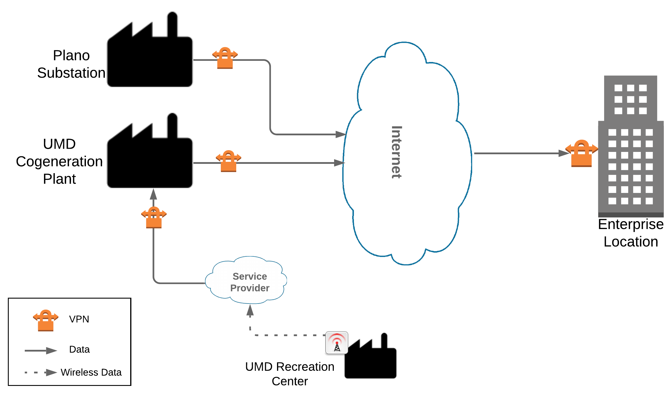
Both the Plano substation and the UMD cogeneration plant are connected through the internet to the NCCoE energy lab as the enterprise location. Each site is connected via a multipoint, always-on virtual private network (VPN). This allows the NCCoE to aggregate data from multiple sites into a single location, emulating multisite deployments found within the energy sector. The UMD site also consists of a remote site connected via wireless technology. Each site is described in more detail in Section 4.
3.1 Audience
This guide is intended for individuals or entities responsible for cybersecurity of ICS and for those interested in understanding an example architecture demonstrating asset management capabilities for OT. It may also be of interest to anyone in industry, academia, or government who seeks general knowledge of an OT asset management solution for energy-sector organizations.
3.2 Scope
This document focuses on OT asset management, namely devices used to control, monitor, and maintain generation, transmission, and distribution of various forms of energy. These devices include PLCs, IEDs, engineering workstations, historians, and human-machine interfaces (HMIs). This document does not consider software inventories or other physical assets that may be used to support energy operations, such as buildings, trucks, and physical access control systems. The solution is designed to deliver an automated OT asset inventory that provides asset information in real or near real time and can alert personnel of any changes to the inventory. Additionally, we focus on OT asset management from a cybersecurity perspective. Although operational benefits can be obtained from implementation of one or more of the components of this guide, we propose OT asset management as a fundamental and core aspect of properly maintaining an adequate cybersecurity posture.
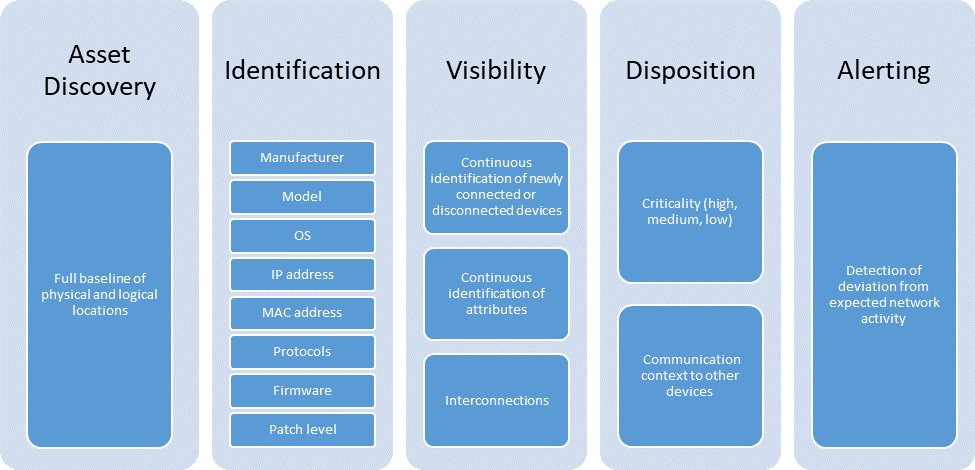
This project addresses the following characteristics of asset management:
Asset Discovery: establishment of a full baseline of physical and logical locations of assets
Asset Identification: capture of asset attributes, such as manufacturer, model, OS, IP addresses, MAC addresses, protocols, patch-level information, and firmware versions
Asset Visibility: continuous identification of newly connected or disconnected devices and IP (routable and non-routable) and serial connections to other devices
Asset Disposition: the level of criticality (high, medium, or low) of a particular asset, its relation to other assets within the OT network, and its communication (including serial) with other devices
Alerting Capabilities: detection of a deviation from the expected operation of assets
Figure 3‑2 Asset Management Characteristics
3.3 Assumptions
This project makes the following assumptions:
The solution will scale to real-world operating environments.
Some level of an asset management capability already exists within an organization.
Although we differentiate between IT and OT asset inventories, there may be some overlap.
All asset data sent to asset collection points has not been compromised.
All OT assets within an organization’s infrastructure, especially those considered critical, need to be identified, tracked, and managed.
OT networks are composed of numerous ICS devices (e.g., PLCs and IEDs) in addition to other vital components (e.g., engineering workstations, historians, and HMIs) that are typically installed on a Windows and/or Linux OS.
NIST / NCCoE considers baseline asset monitoring an essential component of an overall comprehensive cybersecurity monitoring strategy. This guide provides guidance on the asset component of the strategy only, and is not intended to showcase a comprehensive cybersecurity monitoring capability which would likely include, but not be limited to: network and device vulnerabilities, behavioral anomaly detection capabilities, and intrusion detection.
3.4 Risk Assessment
NIST SP 800-30 Revision 1, Guide for Conducting Risk Assessments, states that risk is “a measure of the extent to which an entity is threatened by a potential circumstance or event, and typically a function of: (i) the adverse impacts that would arise if the circumstance or event occurs and (ii) the likelihood of occurrence” [B2]. The guide further defines risk assessment as “the process of identifying, estimating, and prioritizing risks to organizational operations (including mission, functions, image, reputation), organizational assets, individuals, other organizations, and the Nation, resulting from the operation of an information system. Part of risk management incorporates threat and vulnerability analyses, and considers mitigations provided by security controls planned or in place.”
The NCCoE recommends that any discussion of risk management, particularly at the enterprise-level, begins with a comprehensive review of NIST SP 800-37 Revision 2, Risk Management Framework for Information Systems and Organizations—publicly-available material [B3]. The Risk Management Framework guidance, as a whole, proved to be invaluable in giving us a baseline to assess risks, from which we developed the project, the security characteristics of the build, and this guide [B4].
The basis for our assessment of the risks associated with the challenges in asset management for OT is derived from NIST SP 800-82 Revision 2, Guide to Industrial Control Systems (ICS) Security, Section 3. There are certain risks inherent in OT that are not found or that occur rarely in traditional IT environments, for example:
the physical impact a cybersecurity incident could cause to an energy organization’s OT assets and to the larger energy grid
the risk associated with non-digital control components within an OT environment and their lack of visibility within the organization
The NIST Cybersecurity Framework control mapping and related security controls found in this guide are based on these underlying risk concerns.
3.4.1 Threats
A threat is “any circumstance or event with the potential to adversely impact organizational operations” [B5]. If an organization is not aware of its deployed OT assets, it is difficult to protect them and any other assets that may contain known or unknown vulnerabilities. Such lack of awareness increases the risk of exploitation of other networks, devices, and protocol-level vulnerabilities.
The Cybersecurity and Infrastructure Security Agency (CISA) ICS-Computer Emergency Readiness Team (CERT) defines cyber-threat sources to ICS as “persons who attempt unauthorized access to a control system device and/or network using a data communications pathway” [B6]. Specifically, CISA ICS-CERT alongside NIST SP 800-82, Guide to Industrial Control Systems Security [B1], identifies various malicious actors who may pose threats to ICS infrastructure [B6]. These include:
foreign intelligence services–national government organizations whose intelligence-gathering and espionage activities seek to harm U.S. interests
criminal groups–such as organized crime groups that seek to attack for monetary gain
hackers–regarded as the most widely publicized; however, they often possess very little tradecraft to produce large-duration attacks
terrorists–adversaries of the U.S. who are less equipped in their cyber capabilities and therefore pose only a limited cyber threat
At the asset level, CISA ICS-CERT provides alerts and advisories when vulnerabilities for various OT assets are discovered that may pose a threat, if exploited, to ICS infrastructure [B7].
The vulnerabilities are enumerated in the Common Vulnerabilities and Exposures vulnerability naming standard from the MITRE Corporation [B8] and are organized according to severity by high, medium, and low, determined by the Common Vulnerability Scoring System standard from NIST. Common examples of such vulnerabilities include hard-coded credentials, unchanged default passwords, and encryption anomalies [B9].
3.4.2 Vulnerabilities
CISA ICS-CERT defines a vulnerability as a defect that may allow a malicious actor to gain unauthorized access or interfere with normal operations of systems [B10]. A vulnerability may exist inherently within a device or within the design, operation, and architecture of a system. This project does not address securing specific asset-based vulnerabilities at the device level. The key vulnerability addressed then in this guide is an organization not having visibility over its deployed assets.
NIST SP 800-82 categorizes ICS vulnerabilities into the following categories with examples [B1]:
Policy and Procedure–incomplete, inappropriate, or nonexistent security policy, including its documentation, implementation guides (e.g., procedures), and enforcement
Architecture and Design–design flaws, development flaws, poor administration, and connections with other systems and networks
Configuration and Maintenance–misconfiguration and poor maintenance
Physical–lack of or improper access control, malfunctioning equipment
Software Development–improper data validation, security capabilities not enabled, inadequate authentication privileges
Communication and Network–nonexistent authentication, insecure protocols, improper firewall configuration
Knowledge of deployed assets is paramount in securing an organization’s ICS infrastructure and mitigating risks associated with asset-based vulnerabilities. The knowledge of an asset’s location and baselining of its behavior enable detection of anomalous behavior via network monitoring that may be the result of a successfully exploited vulnerability. The ability to reliably detect changes in asset behavior and knowing an asset’s attributes are key in responding to potential cybersecurity incidents.
3.4.3 Risk
Information-system-related security risks are those risks that arise from loss of confidentiality, integrity, or availability of information or information systems and that reflect potential adverse impacts to organizational operations (including mission, functions, image, or reputation), organizational assets, individuals, other organizations, and the nation. For the energy sector, a primary risk concern to OT is a lack of awareness of the devices running on the infrastructure. If OT assets cannot be properly accounted for, they cannot be protected. The following are tactical risks associated with lack of an OT asset management solution:
lack of knowledge of an existing asset, including its configuration and intended behavior
lack of knowledge of the asset’s physical and logical location
lack of a near-real-time comprehensive asset inventory
lack of knowledge of asset vulnerabilities and available patches
lack of data visualization and analysis capabilities that help dispatchers and a security analyst view device security events
3.4.4 Security Control Map
The NIST Cybersecurity Framework security Functions, Categories, and Subcategories that the reference design supports were identified through a risk analysis [B11]. Table 3‑1 below maps NIST SP 800-53 Rev. 4 Security and Privacy Controls [B12], along with industry security references, to the NIST Cybersecurity Framework Subcategories addressed in this practice guide.
Table 3‑1 Security Control Map
Informative References |
||||||||
|---|---|---|---|---|---|---|---|---|
Function |
Category |
Subcategory |
CIS CSC 2016 |
ISA 62443- 2-1:2009 |
ISA 62443- 3-3:2013 |
ISO/IEC 27001: 2013 |
NIST SP 800-53 Rev. 4 |
NERC CIP Standards |
IDENTIFY (ID) |
Asset Management (ID.AM): The data, personnel, devices, systems, and facilities that enable the organization to achieve business purposes are identified and managed consistent with their relative importance to business objectives and the organization’s risk strategy. |
ID.AM-1: Physical devices and systems within the organization are inventoried. |
1 |
4.2.3.4 |
SR 7.8 |
A.8.1.1, A.8.1.2 |
CM-8 PM-5 |
CIP-002-5.1a:R1, R2 CIP-010-2:R1, R2 |
Risk Assessment (ID.RA): The organization understands the cybersecurity risk to organizational operations (including mission, functions, image, or reputation), organizational assets, and individuals. |
ID.RA-2: Threat and vulnerability information is received from information- sharing forums and sources. |
4 |
4.2.3, 4.2.3.9, 4.2.3.12 |
A.6.14 |
A.6.1.4 |
SI‑5, PM-15, PM-16 |
n/a |
|
PROTECT (PR) |
Data Security (PR.DS): Information and records (data) are managed consistent with the organization’s risk strategy to protect the confidentiality, integrity, and availability of information. |
PR.DS-2: Data-in-transit is protected. |
13, 14 |
n/a |
SR 3.1, SR 3.8, SR 4.1, SR 4.2 |
A.8.2.3, A.13.1.1, A.13.2.1, A.13.2.3, A.14.1.2, A.14.1.3 |
SC-8, SC-11, SC-12 |
CIP-005-5:R2 Part 2.2 CIP-011-2:R1 Part 1.2 |
PR.DS-6: Integrity‑ checking mechanisms are used to verify software, firmware, and information integrity. |
2,3 |
n/a |
SR 3.1, SR 3.3, SR 3.4, SR 3.8 |
A.12.2.1, A.12.5.1, A.14.1.2, A.14.1.3, A.14.2.4 |
SC-16, SI-7 |
CIP-010-2:R1, R2, R3 |
||
Maintenance (PR.MA): Maintenance and repair of industrial control and information system components are performed consistent with policies and procedures. |
PR.MA-1: Maintenance and repair of organizational assets are performed and logged in a timely manner, with approved and controlled tools. |
n/a |
4.3.3.3.7 |
n/a |
A.11.1.2, A.11.2.4, A.11.2.5, A.11.2.6 |
MA-2, MA-3, MA-5, MA-6 |
CIP-10-2:R1 |
|
PR.MA-2: Remote maintenance of organizational assets is approved, logged, and performed in a manner that prevents unauthorized access. |
3, 5 |
4.3.3.6.5, 4.3.3.6.6, 4.3.3.6.7, 4.3.3.6.8 |
n/a |
A.11.2.4, A.15.1.1, A.15.2.1 |
MA-4 |
CIP-010-2:R1 |
||
Protective Technology (PR.PT): Technical security solutions are managed to ensure the security and resilience of systems and assets, consistent with related policies, procedures, and agreements. |
PR.PT-4: Communications and control networks are protected. |
8, 12, 15 |
n/a |
SR 3.1, SR 3.5, SR 3.8, SR 4.1, SR 4.3, SR 5.1, SR 5.2, SR 5.3, SR 7.1, SR 7.6 |
A.13.1.1, A.13.2.1, A.14.1.3 |
AC-4, AC-17, AC-18, CP-8, SC-7, SC-19, SC-20, SC-21, SC-22, SC-23, SC-24, SC-25, SC-29, SC-32, SC-36, SC-37, SC-38, SC-39, SC-40, SC-41, SC-43 |
CIP-005-5:R1 Part 1.2 |
|
DETECT (DE) |
Anomalies and Events (DE.AE): Anomalous activity is detected in a timely manner, and the potential impact of events is understood. |
DE.AE-1: A baseline of network operations and expected data flows for users and systems is established and managed. |
1, 4, 6, 12, 13, 15, 16 |
4.4.3.3 |
n/a |
A.12.1.1, A.12.1.2, A.13.1.1, A.13.1.2 |
AC-4, CA‑3, CM‑2, SI-4 |
CIP-010-2:R1 |
DE.AE-3: Event data is aggregated and correlated from multiple sources and sensors. |
1, 3, 4, 5, 6, 7, 8, 11, 12, 13, 14, 15, 16 |
n/a |
SR 6.1 |
A.12.4.1, A.16.1.7 |
AU-6, CA-7, IR-4, IR-5, IR-8, SI-4 |
CIP-008-5:R1.4 CIP-010-2:R1 |
||
3.4.5 National Initiative for Cybersecurity Education Workforce Framework
This guide details the work roles needed to perform the tasks necessary to implement the cybersecurity Functions and Subcategories detailed in the reference design. The work roles are based on the National Initiative for Cybersecurity Education (NICE) Workforce Framework [B13].
Table 3-2 maps the Cybersecurity Framework Categories implemented in the reference design to the NICE work roles. Note that the work roles defined may apply to more than one NIST Cybersecurity Framework Category.
For more information about NICE and other work roles, the NIST SP 800-181, NICE Cybersecurity Workforce Framework, is available at https://nvlpubs.nist.gov/nistpubs/specialpublications/nist.sp.800-181.pdf.
Table 3‑2 NIST NICE Work Roles Mapped to the Cybersecurity Framework: ESAM
Work Role ID |
Work Role |
Work Role Description |
Category |
Specialty Area |
Cybersecurity Framework Subcategory Mapping |
|---|---|---|---|---|---|
OM-STS-001 |
Technical Support Specialist |
Provides technical support to customers who need assistance utilizing client-level hardware and software in accordance with established or approved organizational process components (i.e., Master Incident Management Plan, when applicable). |
Operate and Maintain |
Customer Service and Technical Support |
ID.AM-1 |
PR-VAM-001 |
Vulner-ability Assess-ment Analyst |
Performs assessments of systems and networks within the network environment or enclave and identifies where those systems/networks deviate from acceptable configurations, enclave policy, or local policy. Measures effectiveness of defense-in-depth architecture against known vulnerabilities. |
Protect and Defend |
Vulnerability Assessment Management |
ID.RA-2 |
OM-DTA-002 |
Infor-mation Systems Security Developer |
Examines data from multiple disparate sources, with the goal of providing security and privacy insight. Designs and implements custom algorithms, workflow processes, and layouts for complex, enterprise-scale data sets used for modeling, data mining, and research purposes. |
Operate and Maintain |
Data Administration |
PR.DS-2 |
PR-CDA-001 |
Cyber Defense Analyst |
Uses data collected from a variety of cyber defense tools (e.g., IDS alerts, firewalls, network traffic logs) to analyze events that occur within their environments, to mitigate threats. |
Protect and Defend |
Cyber Defense Analysis |
PR.DS-2 |
OM-DTA-001 |
Database Admin-istrator |
Administers databases and data management systems that allow secure storage, query, protection, and utilization of data. |
Operate and Maintain |
Data Administration |
PR.DS-6 |
OM-ADM-001 |
System Admin-istrator |
Responsible for setting up and maintaining a system or specific components of a system (e.g., installing, configuring, and updating hardware and software; establishing and managing user accounts; overseeing or conducting backup and recovery tasks; implementing operational and technical security controls; and adhering to organizational security policies and procedures). |
Operate and Maintain |
Systems Administration |
PR.MA-1 |
SP-TRD-001 |
Research & Develop-ment Specialist |
Conducts software and systems engineering and software systems research to develop new capabilities, ensuring cybersecurity is fully integrated. Conducts comprehensive technology research to evaluate potential vulnerabilities in cyber space systems. |
Securely Provision |
Technology R&D |
PR.MA-2 |
SP-ARC-002 |
Security Architect |
Ensures stakeholder security requirements necessary to protect the organization’s mission and business processes are adequately addressed in all aspects of enterprise architecture, including reference models, segment and solution architectures, and the resulting systems supporting those missions and business processes. |
Securely Provision |
Systems Architecture |
PR.PT-4 |
SP-ARC-001 |
Enterprise Architect |
Develops and maintains business, systems, and information processes to support enterprise mission needs; develops IT rules and requirements that describe baseline and target architectures. |
Securely Provision |
Systems Architecture |
DE.AE-1 |
CO-OPS-001 |
Cyber Operator |
Conducts collection, processing, and geo-location of systems to exploit, locate, and track targets of interest. Performs network navigation and tactical forensic analysis and, when directed, executes on-net operations. |
Collect and Operate |
Cyber Operations |
DE.AE-3 |
3.5 Technologies
Table 3-3 lists all of the technologies and their role in this project and provides a mapping among the generic application term, the specific product used, and the security control(s) that the product provides. Refer to Table 3-1 for an explanation of the NIST Cybersecurity Framework Subcategory codes.
Table 3‑3 Products and Technologies
Capability |
Product |
Project Role |
Cybersecurity Framework Subcategories |
|---|---|---|---|
Asset discovery and monitoring |
Dragos Platform v1.5 |
Passive asset discovery, threat detection, and incident response for ICS networks |
ID.AM-1, DE.AE-1, DE.AE-2 |
Data collection and inventory tool |
ForeScout CounterACT v8.0.1 |
CounterACT appliance collects data from one location and reports back to the CounterACT Enterprise Manager on the enterprise network. |
ID.AM-1, DE.AE-1, DE.AE-2 |
Asset identification, analysis, and baselining |
FoxGuard Solutions Patch and Update Management Program v1 |
Patch availability reporting is an ICS security patch management report that consolidates patch sources into one source. |
ID.RA-2 |
Vulnerability Notification Report is curated specific to your asset list, putting critical security vulnerability data at your fingertips for your assets. |
|||
ICS Update Tool consumes monthly security-patch- availability reports and translates them into a dashboard of business analytics. This visualization of patch data provides near-real-time decision-making. |
|||
Secure remote access |
KORE Wireless, Inc. Cellular Connectivity with Cellular Gateway v2.0 |
Provide a secure bridge from remote devices via one or more long-term evolution (LTE) networks to the application server on the ICS network that gathers the data from the remote asset. |
PR.DS-2, PR.MA-1 |
Analyzing and visualizing machine data |
Splunk Enterprise v7.1.3 |
Provides capabilities for data collection, indexing, searching, reporting, analysis, alerting, monitoring, and visualization. |
DE.AE-1, DE.AE-2 |
Data Collection, monitoring, and analysis |
TDi Technologies, Inc. ConsoleWorks v5.2-0u1 |
Provides data collection and interfacing with serial conversion devices. Also provides analysis and reporting. |
ID.AM-1, PR.DS-2 |
Anomaly detection |
Tripwire Industrial Visibility v3.2.1 |
Passively scans the industrial control environments at two locations. Tripwire Industrial Visibility builds a baseline of assets and network traffic between those assets then alerts on anomalous traffic. |
ID.AM-1, DE.AE-1, DE.AE-2 |
4 Architecture
The project architecture focuses on the key capabilities of asset management: asset discovery, identification, visibility, disposition, and alerting capabilities. When combined, these capabilities allow an organization to have a more robust understanding, not only of its device inventory and architecture but also of the current state of its devices and automated alerts for anomalous behavior of its assets.
This section presents a high-level architecture, a reference design, detailed topologies, and a visualization dashboard for implementing such a solution. The high-level architecture is a generic representation of the reference design. The reference design includes a broad set of capabilities available in the marketplace, to illustrate the ESAM capabilities noted above, that an organization may implement. Each topology depicts the physical architecture of the example solution. The asset management dashboard displays the network connectivity between devices and a list of known assets within the network. The NCCoE understands that an organization may not need all of the capabilities. An organization may choose to implement a subset of the capabilities, depending on its risk management decisions.
4.1 Architecture Description
4.1.1 High-Level Architecture
The ESAM solution is designed to address the Cybersecurity Framework Functions, Categories, and Subcategories described in Table 3-1 and is depicted in Figure 3-1.
Figure 4‑1 High-Level Architecture
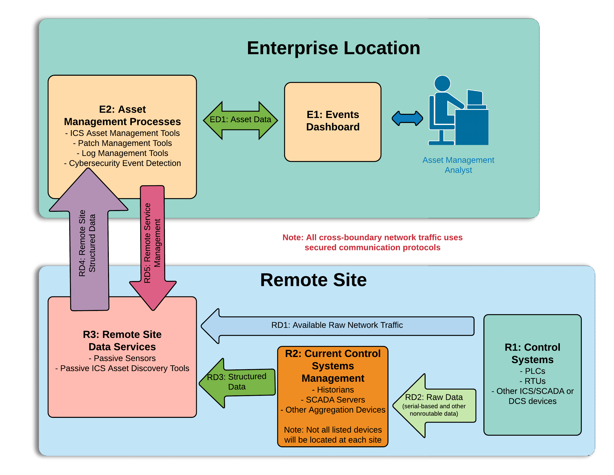
Figure 4-1 depicts the high-level architecture for monitoring ICS assets, including those located in remote sites. While one remote site is depicted, the architecture allows inclusion of multiple remote sites. This allows a repeatable and standard framework of deployment and strategy for multiple remotes sites, which can be tailored to individual site needs.
The high-level architecture (Figure 4-1) above is best described starting at the remote site control systems. Information at this level appears as raw ICS-based data (including serial communications), ICS-based network traffic (Distributed Network Protocol 3, Modbus, EtherIP, etc.), or raw networking data (Transmission Control Protocol [TCP]/User Datagram Protocol, internet control message protocol [ICMP], address resolution protocol [ARP], etc.). Serial communications are encapsulated in network protocols. All of this data is collected and stored by the remote site data servers (R3) object. These sensors are collecting ICS network traffic and raw IP networking data from the control systems (R1) and current control systems management (R2). Data collected by the remote site data servers (R3) is sent through a VPN tunnel to listening servers in the enterprise location. Once data arrives from the remote site at the enterprise-data-collection server, it is ingested into the assets management processes (E2). These tools aggregate the remote site structured data (RD4) from multiple sites, to build a holistic picture of the health and setup of the network. Next, both events and asset data from the asset management processes (E2) tools are sent directly to the events dashboard (E1). In the events dashboard (E1), events are displayed in an easily digestible format for an analyst.
In the event of needed configuration of remote site data servers (R3), remote service management connections can be established between the asset management processes (E2) and the remote site data servers (R3). This traffic is routed through the aforementioned VPN tunnel and is terminated inside the remote site data servers (R3). This allows configuration solely in the remote site data servers (R3), utilizing the established VPN tunnel for security, without allowing access to either the current control systems management (R2) or control systems (R3) devices.
4.1.2 Reference Architecture
The reference architecture shown in Figure 4-2 depicts the detailed ESAM design, including relationships among the included capabilities.
Figure 4‑2 Reference Architecture
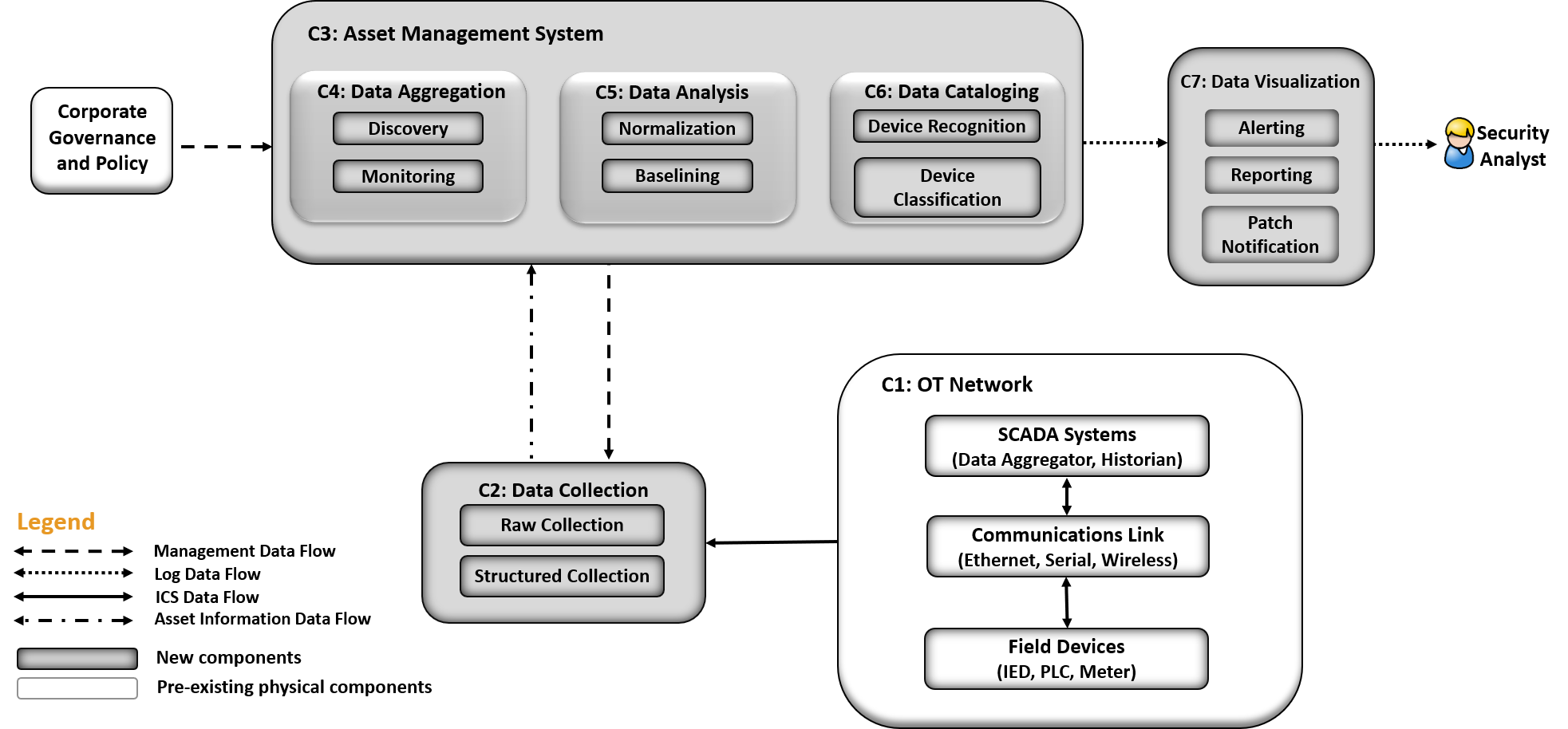
As indicated by the legend, different lines represent different types of data flowing into the various components. ICS data is depicted with solid lines. Management data flow is depicted with the dashed line. Asset information is depicted with a dot-dash line. Log data is depicted with a dotted line. Each of the clear shapes represents a preexisting or optional component. The OT network consists of devices composed of ICS-based data, ICS network traffic, or raw networking data. The example implementation includes the ICS devices in both the UMD cogeneration plant as well as TDi’s lab in Plano, Texas, in the Reference Design OT Network categorization group.
Another component that utilizes the ESAM solution is corporate governance and policy. Corporate governance and policy may guide different aspects of the ESAM solution, such as how long records will be maintained, how to classify devices, and how often reports are run. Each organization’s governance and policy will be determined by organizational risk tolerance and management decisions.
The components of the ESAM reference design, Figure 4-2, come together to form the asset management system. Each capability is described below:
The data collection capability captures the data from the in-place OT network. Data can be collected in raw packet capture form as well as any structured form that may come from tools or devices within the OT network. This capability can be configured through normal remote management channels, to ensure the most precise and policy-informed data ingestion needed for the organization.
The data aggregation component ingests data from the data collection capability and utilizes both the discovery capability and monitoring capability. The monitoring capability tracks network activity collected from the OT network. After a training period, the discovery capability identifies new devices when new IP addresses and MAC addresses are communicating on the network.
The data analysis capability utilizes both a normalization capability to bring in traffic from multiple sites into a single picture and a baselining capability to establish an informed standard of how an asset’s network traffic should behave under normal operations.
The device cataloging capability simultaneously uses information from the data collection component. The device recognition capability identifies different types of devices within the system. Devices are identified by MAC address to determine the manufacturer or by deep-packet inspection to determine the model, serial number, or both of a device if the raw ICS protocol contains such information. Figure 4-4 below depicts the option for determining the serial and model number of a device, when scanning is technically feasible. The organization should verify compliance with relevant regulations before deploying this aspect of the solution. Next, the device classification capability can determine the level of criticality for devices, both automatically as well as manually if requested.
The data visualization capability displays data from components of the asset management system. Here, the alerting capability notifies analysts of incidents, including deviations to normal behaviors. This component also includes the reporting capability to generate timely reports needed in operations of the organization. One key feature of the reporting capability is the ability to report when a cybersecurity patch is available.
4.2 Example Solution
Below are topologies for three separate sites utilized for this project along with their asset management dashboard displays. The project employs network test access points (TAPs) that fail open, allowing network traffic to continue passing in the event of device failure. There are other examples of connectivity decisions used, including the use of Switched Port Analyzer (SPAN) ports, that are utilized specifically to facilitate the capture of data for the project. This approach represents one method to collect data.
4.2.1 UMD Site Topology
Figure 4‑3 UMD In-Depth Topology
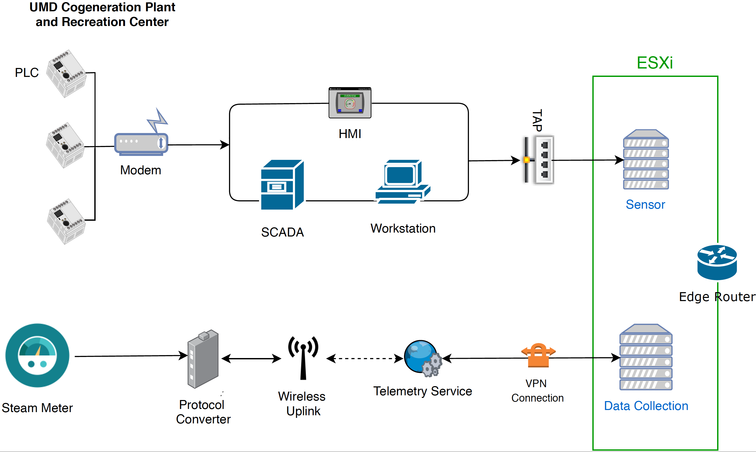
UMD’s cogeneration plant was utilized as one of the remote sites for the project. At the site, the control system network consists of PLCs, networking equipment, operator workstations, HMIs, and Supervisory Control and Data Acquisition (SCADA) servers. The control system network is fitted with network TAPs to collect network traffic from the ICS network. This traffic feeds into a port on the ESXi server that is mapped to a virtual SPAN switch. Each sensor monitors traffic on the SPAN switch. The sensor collects the raw data, processes network packets, performs deep-packet inspection, and forwards structured data through the edge router to an asset management server, as shown above in Figure 4-3.
The UMD site topology also consists of a steam-meter asset in the solution. The steam meter utilizes highway addressable remote transducer (HART) communication protocol and is in a building separate from the cogeneration plant. The steam meter is wired to a protocol converter that converts HART communications to Ethernet. The wireless uplink is a cellular connection device providing wireless connectivity to the telemetry service provider. A VPN connection links the data collection server to the telemetry service provider, which allows data to be read from the steam meter.
Following collection of data from both the control system network and the steam meter to the VMware ESXi servers, the data is then sent through a VPN tunnel out of the edge router to the enterprise location. A description of the enterprise location is found in Section 4.2.3.
4.2.2 Plano Site Topology
Figure 4‑4 Plano In-Depth Topology
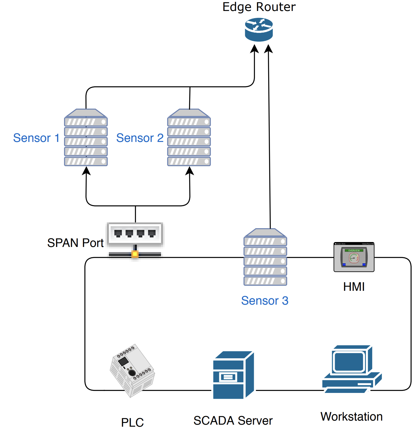
The lab in Plano, Texas, depicted in Figure 4-4, represents a second site and is set up to collect information from a variety of devices communicating on a network. The Plano site consist of PLCs, HMIs, SCADA servers, and workstations. Sensor 1 and Sensor 2 passively monitor devices via a SPAN port. Both sensors are collecting data. Sensor 3 has a network interface located on the control network, to demonstrate the ability to actively scan devices if desired. Actively scanning devices requires scripts to interrogate devices by using a method supported by the device. Methods may include using login credentials or combinations of commands to retrieve data from the device. Typically, similar devices from the same manufacturer can utilize similar scripts. Otherwise, most device types require unique scripts. Most devices can be scanned or polled to retrieve the model number, serial number, and more. All three sensors transfer their data, via the edge router, through a VPN to the enterprise location.
4.2.3 Enterprise Location Topology
Figure 4‑5 Enterprise In-Depth Topology
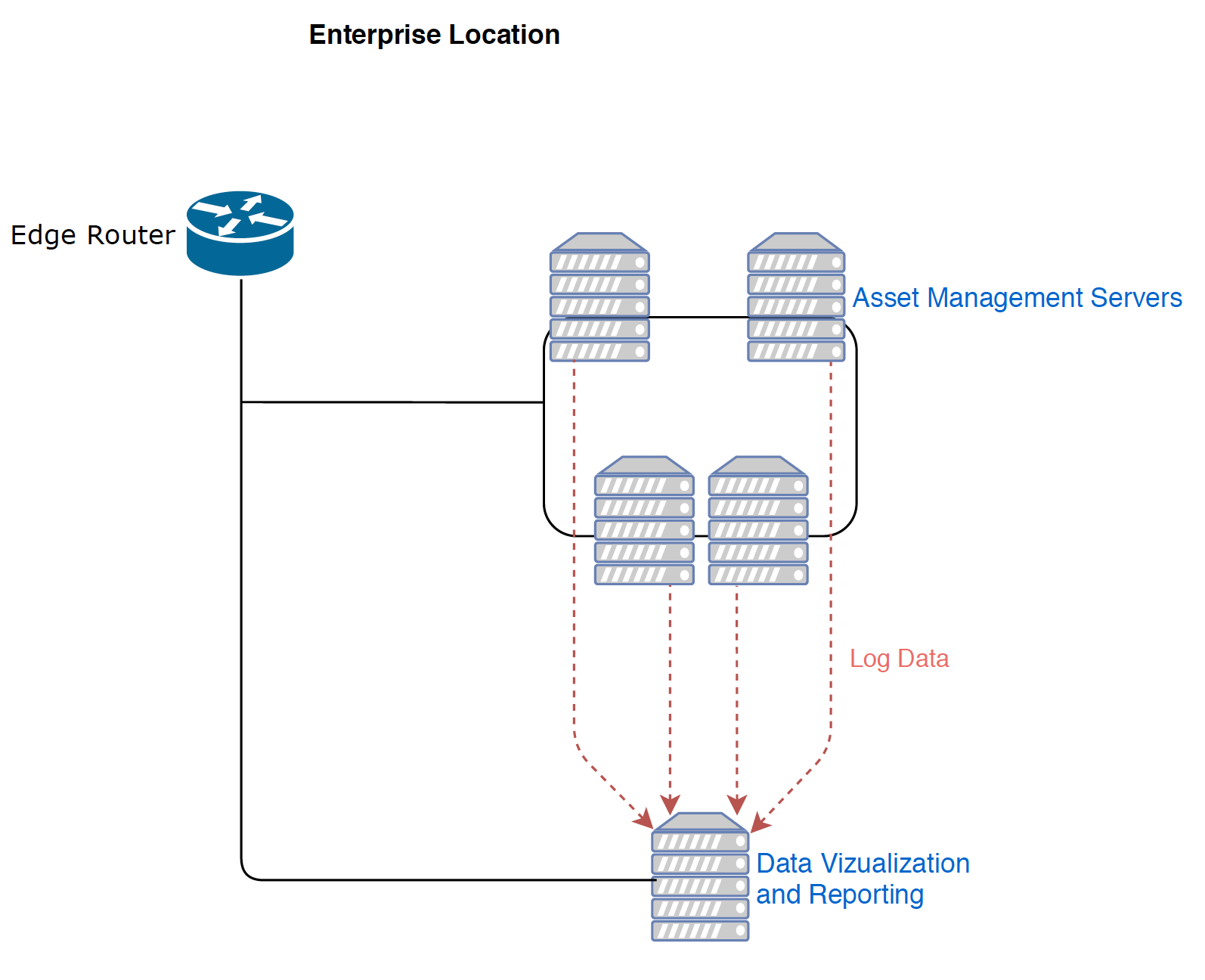
The enterprise location in the NCCoE Lab (Rockville, Maryland), depicted in Figure 4-5, represents a central operations center for an organization. Data from both the Plano and UMD sites is sent to the enterprise location, for processing through the asset management servers.
The asset management servers aggregate the data, analyze the data, and catalog the details about the assets currently on the network, incorporating both remote sites. Portions of this data are logged and forwarded to the data visualization and reporting server. First, alerts on new baselines and baseline deviations are forwarded via syslog. Alerts on asset changes, including new assets, changes in IP and MAC addresses, and offline assets, are forwarded via syslog along with identified threats to those assets. Last, a comma-separated value (CSV) asset report is automatically forwarded on a regular basis to maintain an updated and near-real-time asset inventory.
4.2.4 Asset Management Dashboard
Note: IP addresses shown in the figures below have been sanitized.
Figure 4‑6 Asset Dashboard: Asset Characteristics
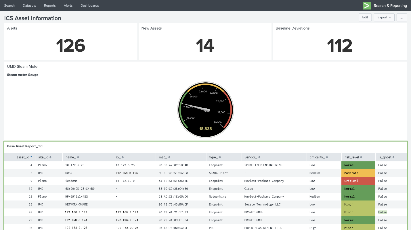
Figure 4-6 showcases how the asset management dashboard displays a list of known assets within the network. At the top of the dashboard, the total amount of alerts, number of new assets, and number of baseline deviations detected from both the Plano and UMD locations are listed. The gauge displays the meter reading from the Yokogawa steam meter at UMD. Information collected on each asset (including IP address, MAC address, asset type, criticality, and risk level) is displayed in the table.
Figure 4‑7 Asset Dashboard: Asset Communications
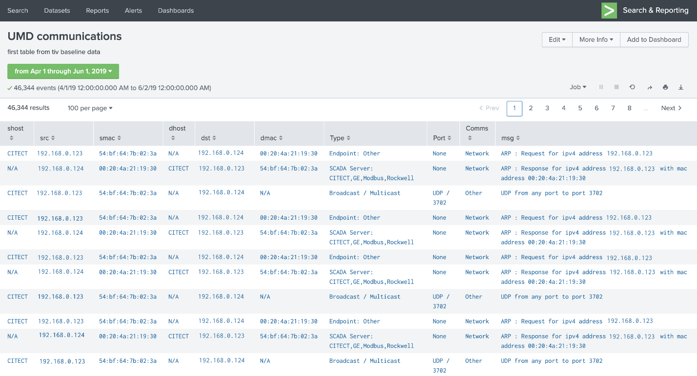
Figure 4-7 showcases the asset management dashboard visualization of network connectivity among devices. The visualization shows the interconnection among known assets, listing types of communications and messages.
Figure 4‑8 Asset Dashboard: Asset Details, UMD
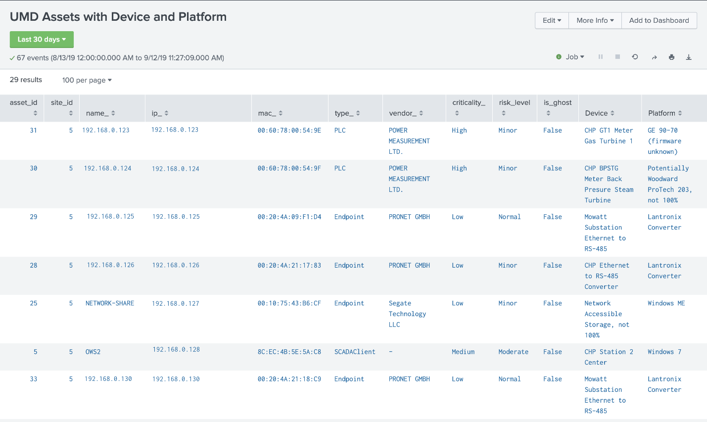
Figure 4-8 showcases more detailed information about assets at the UMD location. The asset information is supplemented with known data about the devices.
Figure 4‑9 Asset Dashboard: Asset Details, Plano
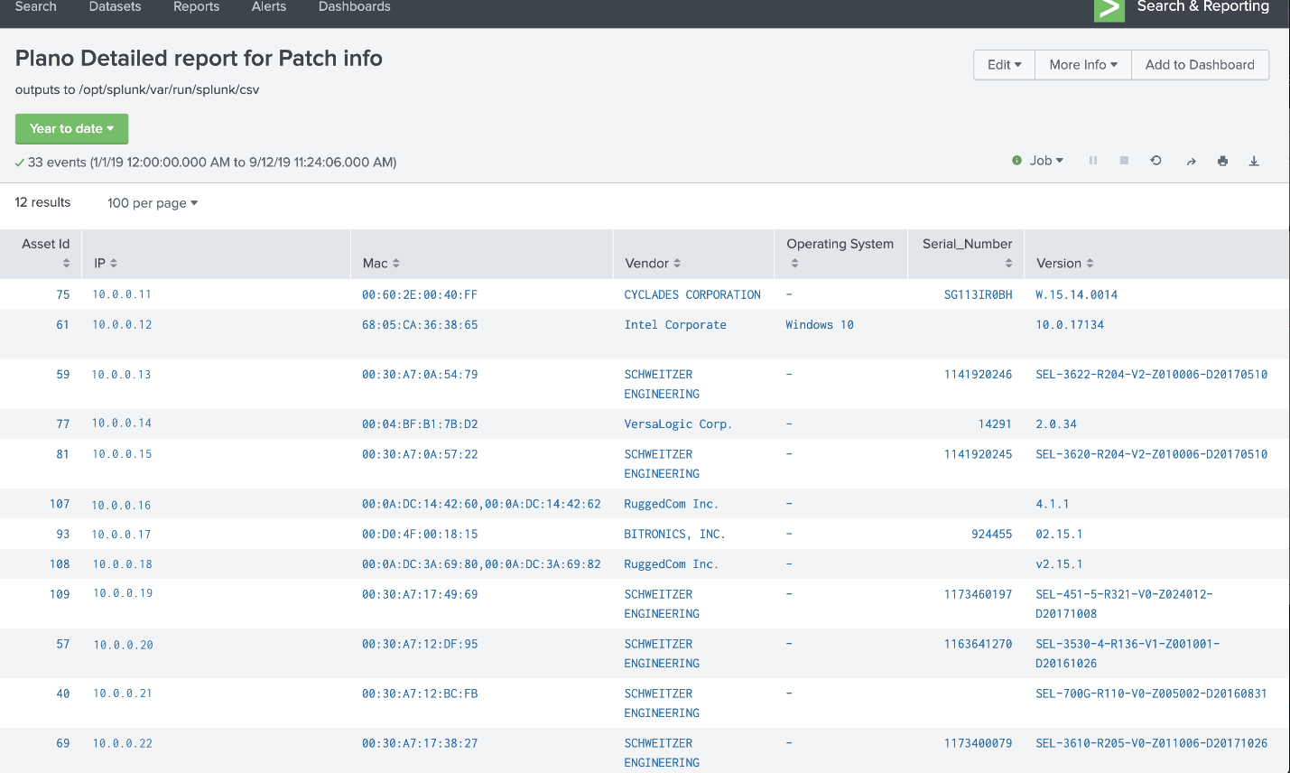
Figure 4-9 showcases more detailed information about assets at the Plano location. The asset information is supplemented via automated scripts and manual entry. This report is normalized and then analyzed for patch notifications.
5 Functional Test Plan
5.1 Test Cases
The below test cases demonstrate integration of capabilities for use in the project. For reference, components of Figure 4-1 High-Level Architecture and Figure 4-2 Reference Architecture are included with their corresponding identifier tags in parenthesis.
5.1.1 ESAM-1: New Device Attached
Description |
|
|---|---|
Procedure |
|
Architectural Requirements |
|
Capabilities Requirements |
|
Expected Results |
Events Dashboard (E1) will notify analyst via alerts for new devices. |
Actual Results |
|
Overall Result |
PASS |
5.1.2 ESAM-2: Vulnerability Notification
Description |
|
|---|---|
Procedure |
|
Architectural Requirements |
|
Capabilities Requirements |
|
Expected Results |
Analyst will receive reported information in Events Dashboard and will be able to identify potentially vulnerable devices. |
Actual Results |
|
Overall Result |
PASS |
5.1.3 ESAM-3: Device Goes Offline
Description |
|
|---|---|
Procedure |
|
Architectural Requirements |
|
Capabilities Requirements |
|
Expected Results |
Events Dashboard (E1) will notify analyst via alerts for loss of connection to device(s). |
Actual Results |
|
Overall Result |
PASS |
5.1.4 ESAM-4: Anomalous Device Communication
Description |
|
|---|---|
Procedure |
|
Architectural Requirements |
|
Capabilities Requirements |
|
Expected Results |
Events Dashboard (E1) will notify analyst via alerts for anomalous device activity. |
Actual Results |
|
Overall Result |
PASS |
5.1.5 ESAM-5: Remote Devices with Cellular Connectivity
Description |
|
|---|---|
Procedure |
|
Architectural Requirements |
|
Capabilities Requirements |
|
Expected Results |
Devices in cellular-based remote sites will also show in the Events Dashboard (E1). |
Actual Results |
|
Overall Result |
PASS |
6 Security Characteristic Analysis
The purpose of the security characteristic analysis is to understand the extent to which the project meets its objective of demonstrating asset management for OT. A key aspect of our security evaluation involved assessing how well the reference design addresses the security characteristics it was intended to support. The Cybersecurity Framework Subcategories were used to provide structure to the security assessment, by consulting the specific sections of each standard cited in reference to a Subcategory [B14]. The cited sections provide validation points that the example solution would be expected to exhibit. Using the Cybersecurity Framework Subcategories as a basis for organizing our analysis allowed us to systematically consider how well the reference design supports the intended security characteristics.
6.1 Assumptions and Limitations
The security characteristic analysis has the following limitations:
It is neither a comprehensive test of all security components nor a red-team exercise.
It cannot identify all weaknesses.
It does not include the lab infrastructure. It is assumed that devices are hardened. Testing these devices would reveal only weaknesses in implementation that would not be relevant to those adopting this reference architecture.
6.2 Analysis of the Reference Design’s Support for Cybersecurity Framework Subcategories
This section analyzes the example implementation in terms of the specific Subcategories of the Cybersecurity Framework that they support. This enables an understanding of how the example implementation achieved the goals of the design when compared against a standardized framework. This section identifies the security benefits provided by each component of the example implementation and how those components support specific cybersecurity activities, as specified in terms of Cybersecurity Framework Subcategories.
6.2.1 ID.AM-1: Physical Devices and Systems Within the Organization Are Inventoried
The ESAM reference design employs multiple applications that keep inventory of devices. Using passive analysis of network communications as well as device polling, the design captures relevant data about each asset within the scope of the build, to give an asset owner insight into what devices are deployed.
The reference design notifies on device installation, updates, and removals, helping maintain an up-to-date, complete, accurate, and readily available inventory of system components. These processes are automated, allowing an organization to have a central repository for inventory of assets as well as for specifying roles played by those assets.
Some devices may prove difficult to inventory. If a device utilizes communications not initially monitored by the ESAM reference design, the device will not be captured in the inventory. The ESAM reference design employs an optional active scanning process that can resolve this situation.
6.2.2 ID.RA-2: Threat and Vulnerability Information Is Received from Information-Sharing Forums and Sources
The ESAM reference design implements a patch and vulnerability intelligence solution through vendor-provided reporting. Utilizing asset lists described above, patch and vulnerability information is provided by the vendor product, to relay system security alerts and advisories to analysts.
The reference design allows an organization to be aware of potential vulnerabilities that may be applicable in the network and to the organization’s assets. The design informs an organization whether assets within its inventory have updates available, if any assets have vulnerabilities, and the criticality of those patches or vulnerabilities. This information is broken out into a per-device format, helping form a more informed decision on updates.
6.2.3 PR.DS-2: Data in Transit Is Protected
The ESAM reference design has multiple remote connections stemming from multiple remote sites. Data is constantly being transmitted across these connections, so protection of these connections is vital. The reference design utilizes VPN connections for all connections going out of an edge-network device.
The VPN connecting the three physically remote sites—namely the enterprise site; UMD; and Plano, Texas—utilizes an always-on, multipoint VPN connection. This connection is using TLS 1.2 and certificate authentication to ensure maximum security as well as maximum reliability.
6.2.4 PR.MA-1: Maintenance and Repair of Organizational Assets Are Performed and Logged in a Timely Manner with Approved and Controlled Tools
The ESAM reference design does not specifically track maintenance scheduling or approvals; however, predictive and preventive maintenance is supported by elements contained in the design. Patch and vulnerability information provided by vendors, combined with information from other sources, can be used by the organization to make informed cybersecurity-maintenance decisions.
This information supports any process that builds maintenance scheduling, allowing an organization to determine what assets should be included in preventive or predictive maintenance times. Although mainly software focused, asset information may include model numbers for devices, allowing an organization to locate and replace specific devices if needed.
6.2.5 PR.MA-2: Remote Maintenance of Organizational Assets Is Approved, Logged, and Performed in a Manner that Prevents Unauthorized Access
The ESAM reference design utilizes connections within the project to allow authenticated remote access to a system. This authentication is predicated on access to the enterprise network, forcing a potential user to first gain access to the asset management network before being able to remotely manage devices.
These connections are then wrapped within the established VPN tunnel, protecting systems from replay attacks or other attacks that require open, repeatable authentication techniques to gain access to a system. This allows a more secure remote management path for devices when manual configuration is required.
6.2.6 PR.PT-4: Communications and Control Networks Are Protected
The ESAM reference design is designed to protect critical devices located within the OT network. For the architecture, any connection pulling data from the control networks utilizes a one-way data connection (currently in the form of a SPAN port or a network TAP) to ensure no externally routable connectivity.
The active scanning device listed within the architecture in Section 4.2.2 is a selective aspect of the design. This would require a two-way connection with the OT network and should be implemented with due discretion. Each organization should verify compliance with the appropriate cybersecurity policies and relevant regulations before implementing this aspect of the solution.
6.2.7 DE.AE-1: A Baseline of Network Operations and Expected Data Flows for Users and Systems Is Established and Managed
The ESAM reference design utilizes passive and active scanning tools to scan the industrial control environments at the two remote locations. These tools build a baseline of assets and network traffic between those assets using machine learning, alerting to any anomalous behavior.
6.2.8 DE.AE-2: Detected Events Are Analyzed to Understand Attack Targets and Methods
The ESAM reference design utilizes discovery and monitoring tools to detect malicious activity from an established baseline of network activity. Any deviation from established baselines will notify organizational analysts to activity not recognized as normal behavior. The analyst will be informed what triggered the alert, allowing them to better respond to the incident.
Along with anomaly detection capabilities, the reference design employs alerting and reporting capabilities based on known attack tactics and techniques. Recognition of these threats also elicits an alert that is reported to the analyst.
6.3 Lessons Learned
Identifying and replicating the infrastructure(s) likely found in an OT operating environment is a challenge. The NCCoE ESAM Team did not limit this build to a lab environment. The team was able to demonstrate effective OT asset management in existing, real-world energy-sector environments with the support of collaborators who offered their infrastructure, resources, personnel, and assets.
While numerous automated capabilities are used to capture and maintain asset information, a significant manual effort will likely be needed to identify assets, especially those that are remote and not connected to an existing network infrastructure. Further, given the variety of assets deployed, we experienced instances where serial communication devices required conversion to IP-based communication protocols. It is critical to establish the necessary communication infrastructure to ensure these devices become part of the main, automated inventory that this project showcases.
While the technology we used is not complex, working through coordination and deployment of the supporting infrastructure and asset management technologies will be a rather large undertaking for any company looking to adopt this solution or any component of it. We highly recommend that executive management support be in place, whether the OT asset management solution is deployed to a specific site or across the entire enterprise.
7 Future Build Considerations
The Industrial Internet of Things, or IIoT, refers to the application of instrumentation and connected sensors and other devices to machinery and vehicles in the transport, energy, and industrial sectors. For the energy sector in particular, distributed energy resources (DERs), such as solar photovoltaic panels and wind turbines, introduce information exchanges between a utility’s distribution control system and the DERs, to manage the flow of energy in the distribution grid. Moreover, the rate at which these IIoT devices are deployed in the energy sector is projected to increase and could introduce asset management and cybersecurity challenges for the sector. Expanding the architecture to include IIoT devices and using IIoT-generated data for near-real-time asset management could ensure secure deployment of these assets and may be explored in a future project.