NIST SPECIAL PUBLICATION 1800-21C
Mobile Device Security:
Corporate-Owned Personally-Enabled (COPE)
Volume C:
How-to Guides
Joshua M. Franklin*
Gema Howell
Kaitlin Boeckl
Naomi Lefkovitz
Ellen Nadeau*
Applied Cybersecurity Division Information Technology Laboratory
Dr. Behnam Shariati
University of Maryland, Baltimore County Department of Computer Science and Electrical Engineering Baltimore, Maryland
Jason G. Ajmo
Christopher J. Brown
Spike E. Dog
Frank Javar
Michael Peck
Kenneth F. Sandlin
The MITRE Corporation McLean, Virginia
*Former employee; all work for this publication done while at employer.
September 2020
Final
This publication is available free of charge from:
https://doi.org/10.6028/NIST.SP.1800-21
The first draft of this publication is available free of charge from: https://www.nccoe.nist.gov/projects/building-blocks/mobile-device-security/enterprise
DISCLAIMER
Certain commercial entities, equipment, products, or materials may be identified by name or company logo or other insignia in order to acknowledge their participation in this collaboration or to describe an experimental procedure or concept adequately. Such identification is not intended to imply special status or relationship with NIST or recommendation or endorsement by NIST or NCCoE; neither is it intended to imply that the entities, equipment, products, or materials are necessarily the best available for the purpose.
National Institute of Standards and Technology Special Publication 1800-21C Natl. Inst. Stand. Technol. Spec. Publ. 1800-21C, 167 pages, (September 2020), CODEN: NSPUE2
FEEDBACK
As a private-public partnership, we are always seeking feedback on our practice guides. We are particularly interested in seeing how businesses apply NCCoE reference designs in the real world. If you have implemented the reference design, or have questions about applying it in your environment, please email us at mobile-nccoe@nist.gov.
All comments are subject to release under the Freedom of Information Act.
NATIONAL CYBERSECURITY CENTER OF EXCELLENCE
The National Cybersecurity Center of Excellence (NCCoE), a part of the National Institute of Standards and Technology (NIST), is a collaborative hub where industry organizations, government agencies, and academic institutions work together to address businesses’ most pressing cybersecurity issues. This public-private partnership enables the creation of practical cybersecurity solutions for specific industries, as well as for broad, cross-sector technology challenges. Through consortia under Cooperative Research and Development Agreements (CRADAs), including technology partners—from Fortune 50 market leaders to smaller companies specializing in information technology security—the NCCoE applies standards and best practices to develop modular, adaptable example cybersecurity solutions using commercially available technology. The NCCoE documents these example solutions in the NIST Special Publication 1800 series, which maps capabilities to the NIST Cybersecurity Framework and details the steps needed for another entity to re-create the example solution. The NCCoE was established in 2012 by NIST in partnership with the State of Maryland and Montgomery County, Maryland.
NIST CYBERSECURITY PRACTICE GUIDES
NIST Cybersecurity Practice Guides (Special Publication 1800 series) target specific cybersecurity challenges in the public and private sectors. They are practical, user-friendly guides that facilitate the adoption of standards-based approaches to cybersecurity. They show members of the information security community how to implement example solutions that help them align with relevant standards and best practices, and provide users with the materials lists, configuration files, and other information they need to implement a similar approach.
The documents in this series describe example implementations of cybersecurity practices that businesses and other organizations may voluntarily adopt. These documents do not describe regulations or mandatory practices, nor do they carry statutory authority.
ABSTRACT
Mobile devices provide access to vital workplace resources while giving employees the flexibility to perform their daily activities. Securing these devices is essential to the continuity of business operations.
While mobile devices can increase efficiency and productivity, they can also leave sensitive data vulnerable. Mobile device management tools can address such vulnerabilities by helping secure access to networks and resources. These tools are different from those required to secure the typical computer workstation.
This practice guide focuses on security enhancements that can be made to corporate-owned personally-enabled (COPE) mobile devices. COPE devices are owned by an enterprise and issued to an employee. Both the enterprise and the employee can install applications onto the device.
To address the challenge of securing COPE mobile devices while managing risks, the NCCoE at NIST built a reference architecture to show how various mobile security technologies can be integrated within an enterprise’s network.
This NIST Cybersecurity Practice Guide demonstrates how organizations can use standards-based, commercially available products to help meet their mobile device security and privacy needs.
KEYWORDS
Corporate-owned personally-enabled; COPE; mobile device management; mobile device security, on-premise; bring your own device; BYOD
ACKNOWLEDGEMENTS
We are grateful to the following individuals for their generous contributions of expertise and time.
Name |
Organization |
|---|---|
Donna Dodson |
NIST |
Vincent Sritapan |
Department of Homeland Security, Science and Technology Directorate |
Jason Frazell |
Appthority (acquired by Symantec—A division of Broadcom) |
Joe Midtlyng |
Appthority (acquired by Symantec—A division of Broadcom) |
Chris Gogoel |
Kryptowire |
Tom Karygiannis |
Kryptowire |
Tim LeMaster |
Lookout |
Victoria Mosby |
Lookout |
Michael Carr |
MobileIron |
Walter Holda |
MobileIron |
Farhan Saifudin |
MobileIron |
Jeff Lamoureaux |
Palo Alto Networks |
Sean Morgan |
Palo Alto Networks |
Kabir Kasargod |
Qualcomm |
Viji Raveendran |
Qualcomm |
Lura Danley |
The MITRE Corporation |
Eileen Durkin |
The MITRE Corporation |
Sallie Edwards |
The MITRE Corporation |
Marisa Harriston |
The MITRE Corporation |
Milissa McGinnis |
The MITRE Corporation |
Nick Merlino |
The MITRE Corporation |
Doug Northrip |
The MITRE Corporation |
Titilayo Ogunyale |
The MITRE Corporation |
Oksana Slivina |
The MITRE Corporation |
Tracy Teter |
The MITRE Corporation |
Paul Ward |
The MITRE Corporation |
The Technology Partners/Collaborators who participated in this build submitted their capabilities in response to a notice in the Federal Register. Respondents with relevant capabilities or product components were invited to sign a Cooperative Research and Development Agreement (CRADA) with NIST, allowing them to participate in a consortium to build this example solution. We worked with:
Technology Partner/Collaborator |
Build Involvement |
|---|---|
Appthority Cloud Service, Mobile Threat Intelligence |
|
Kryptowire Cloud Service, Application Vetting |
|
Lookout Cloud Service/Lookout Agent Version 5.10.0.142 (iOS), 5.9.0.420 (Android), Mobile Threat Defense |
|
MobileIron Core Version 9.7.0.1, MobileIron Agent Version 11.0.1A (iOS), 10.2.1.1.3R (Android), Enterprise Mobility Management |
|
Palo Alto Networks PA-220 |
|
Qualcomm Trusted Execution Environment (version is device dependent) |
*Appthority (acquired by Symantec—A division of Broadcom)
List of Figures
Figure 1‑1 Logical Architecture Summary
Figure 2‑1 MobileIron Repository Configuration
Figure 2‑2 MobileIron Core Version
Figure 2‑3 MobileIron Download Status
Figure 2‑4 Validating Database Data
Figure 2‑5 Validating Database Data Confirmation
Figure 2‑6 Database Data Validation Initiation Confirmation
Figure 2‑7 Database Data Validation Status
Figure 2‑8 Software Updates Reboot Prompt
Figure 2‑9 Software Update Reboot Confirmation
Figure 2‑10 Reboot Configuration Save Prompt
Figure 2‑12 Ability to Upgrade to 9.7.0.1
Figure 2‑15 LDAP User Configuration
Figure 2‑16 LDAP Group Configuration
Figure 2‑17 Selected LDAP Group
Figure 2‑18 LDAP Advanced Options
Figure 2‑19 Testing LDAP Configuration
Figure 2‑20 LDAP Test Result 1
Figure 2‑21 MobileIron Device Labels
Figure 2‑22 Adding a Device Label
Figure 2‑23 Device Label Matches
Figure 2‑24 MobileIron Label List
Figure 2‑25 MobileIron SCEP Configuration
Figure 2‑26 Test SCEP Certificate Configuration
Figure 2‑27 Test SCEP Certificate
Figure 2‑28 MobileIron VPN Configuration
Figure 2‑29 Palo Alto Networks Management Interface Enabled
Figure 2‑30 Management Interface Configuration
Figure 2‑31 Palo Alto Networks Firewall General Information
Figure 2‑32 Palo Alto Networks Services Configuration
Figure 2‑35 Ethernet Interfaces
Figure 2‑36 Ethernet Interface Configuration
Figure 2‑37 WAN Interface IPv4 Configuration
Figure 2‑38 WAN Interface IP Address Configuration
Figure 2‑39 Completed WAN Interface Configuration
Figure 2‑40 Security Zone List
Figure 2‑41 LAN Security Zone Configuration
Figure 2‑42 Virtual Router Configuration
Figure 2‑43 Virtual Router General Settings
Figure 2‑44 SSL VPN Tunnel Interface
Figure 2‑45 Application Categories
Figure 2‑46 MobileIron Core Palo Alto Networks Application Configuration
Figure 2‑47 MobileIron Application Port Configuration
Figure 2‑48 DMZ Access to MobileIron Firewall Rule Configuration
Figure 2‑49 DMZ Access to MobileIron Security Rule Source Zone Configuration
Figure 2‑50 DMZ Access to MobileIron Security Rule Destination Address Configuration
Figure 2‑51 DMZ Access to MobileIron Security Rule Application Protocol Configuration
Figure 2‑52 DMZ Access to MobileIron Security Rule Action Configuration
Figure 2‑54 Outbound NAT Original Packet Configuration
Figure 2‑55 Outbound NAT Translated Packet Configuration
Figure 2‑57 Authentication Profile
Figure 2‑58 Advanced Authentication Profile Settings
Figure 2‑59 LDAP Group Mapping
Figure 2‑60 LDAP Group Include List
Figure 2‑61 Authentication Policy Source Zones
Figure 2‑62 Authentication Policy Destination Zones
Figure 2‑63 Authentication Profile Actions
Figure 2‑64 Import MobileIron Certificate
Figure 2‑65 Certificate Profile
Figure 2‑66 Internal Root Certificate Profile
Figure 2‑67 SSL/TLS Service Profile
Figure 2‑68 Custom URL Category
Figure 2‑69 URL Filtering Profile
Figure 2‑70 URL Filtering Security Policy
Figure 2‑71 General GlobalProtect Gateway Configuration
Figure 2‑72 GlobalProtect Authentication Configuration
Figure 2‑73 GlobalProtect Tunnel Configuration
Figure 2‑74 VPN Client IP Pool
Figure 2‑75 VPN Client Settings
Figure 2‑76 VPN Authentication Override Configuration
Figure 2‑77 VPN User Group Configuration
Figure 2‑78 VPN Split Tunnel Configuration
Figure 2‑79 GlobalProtect Portal Configuration
Figure 2‑80 GlobalProtect Portal SSL/TLS Configuration
Figure 2‑81 GlobalProtect External Gateway Configuration
Figure 2‑82 GlobalProtect Portal Agent Configuration
Figure 2‑84 Threat Update Schedule
Figure 2‑86 Kryptowire API User Configuration
Figure 2‑87 MobileIron User List
Figure 2‑88 Kryptowire API User Space Assignment
Figure 2‑89 Kryptowire Device List
Figure 2‑90 MobileIron User List
Figure 2‑91 MobileIron Lookout User Configuration
Figure 2‑92 Lookout MobileIron Admin Account
Figure 2‑93 Lookout Account Space Assignment
Figure 2‑94 MobileIron Label List
Figure 2‑95 MTP Low Risk Label Configuration
Figure 2‑96 MobileIron App Catalog
Figure 2‑97 Adding Lookout for Work to the MobileIron App Catalog
Figure 2‑98 Lookout for Work Application Configuration
Figure 2‑99 Lookout for Work Application Configuration
Figure 2‑100 Lookout for Work AFW Configuration
Figure 2‑101 Apply Lookout for Work to Android Devices
Figure 2‑102 Apply To Labels Dialogue
Figure 2‑103 Lookout for Work with Applied Labels
Figure 2‑104 MobileIron App Catalog
Figure 2‑105 Lookout for Work Selected From iTunes
Figure 2‑106 Lookout for Work App Configuration
Figure 2‑107 Lookout for Work App Configuration
Figure 2‑108 Lookout for Work Managed App Settings
Figure 2‑109 App Catalog with Lookout for Work
Figure 2‑110 Lookout for Work Selected
Figure 2‑111 Apply To Labels Dialogue
Figure 2‑112 App Catalog with Lookout for Work
Figure 2‑113 Importing Managed Application Configuration
Figure 2‑114 plist File Configuration
Figure 2‑115 Lookout Configuration Selected
Figure 2‑116 Apply To Label Dialogue
Figure 2‑117 Lookout Configuration With Labels
Figure 2‑118 Add Lookout Connector Display
Figure 2‑119 Connector Settings
Figure 2‑120 Connector Enrollment Settings
Figure 2‑121 Connector Sync Settings
Figure 2‑122 MobileIron App Control Rule
Figure 2‑123 MobileIron App Control Rule
Figure 2‑124 MTP High Risk Compliance Action
Figure 2‑125 Baseline Policy Selection
Figure 2‑126 MTP High Risk Policy
Figure 2‑127 Security Policy Trigger
Figure 2‑129 Apply To Label Dialogue
Figure 2‑130 Appthority User Settings
Figure 2‑131 Appthority Connector User
Figure 2‑132 Appthority Connector Space Assignment
Figure 2‑133 Appthority Connector CLI Configuration
Figure 2‑134 Appthority EMM Connector Status
Figure 2‑136 Erase iPhone Confirmation
Figure 2‑137 Erase iPhone Final Confirmation
Figure 2‑138 Entering iOS Passcode
Figure 2‑139 iOS Trust Computer Confirmation
Figure 2‑140 Entering Passcode to Trust Computer
Figure 2‑141 Configurator 2 Erase Confirmation
Figure 2‑143 Device Preparation Options
Figure 2‑144 MDM Server Selection
Figure 2‑145 Signing into Apple Account
Figure 2‑146 Organization Assignment Dialogue
Figure 2‑147 Creating an Organization
Figure 2‑148 Supervisory Identity Configuration
Figure 2‑149 Organization Selection
Figure 2‑150 Supervising Identity Selection
Figure 2‑151 Selected Organization
Figure 2‑152 Create an Organization Supervision Identity Configuration
Figure 2‑153 Setup Assistant Configuration
Figure 2‑154 Waiting for iPhone
Figure 2‑155 iOS Device MobileIron Registration Page
Figure 2‑156 Opening Settings Confirmation
Figure 2‑157 Profile Installation
Figure 2‑158 Profile Installation
Figure 2‑159 Profile Installation Warning
Figure 2‑160 Profile Installation Trust Confirmation
Figure 2‑161 Profile Installation Confirmation
Figure 2‑162 Lookout for Work Splash Screen
Figure 2‑163 Lookout for Work Permission Information
Figure 2‑164 Notifications Permissions Prompt
Figure 2‑165 Locations Permission Prompt
Figure 2‑166 Lookout for Work Home Screen
Figure 2‑167 MobileIron AFW Configuration
Figure 2‑168 AFW Configuration
Figure 2‑169 MobileIron Enrollment Process
Figure 2‑171 MobileIron Installation
Figure 2‑172 Accepting AFW Terms and Conditions
Figure 2‑173 MobileIron Privacy Information
Figure 2‑174 MobileIron Configuration Required Notification
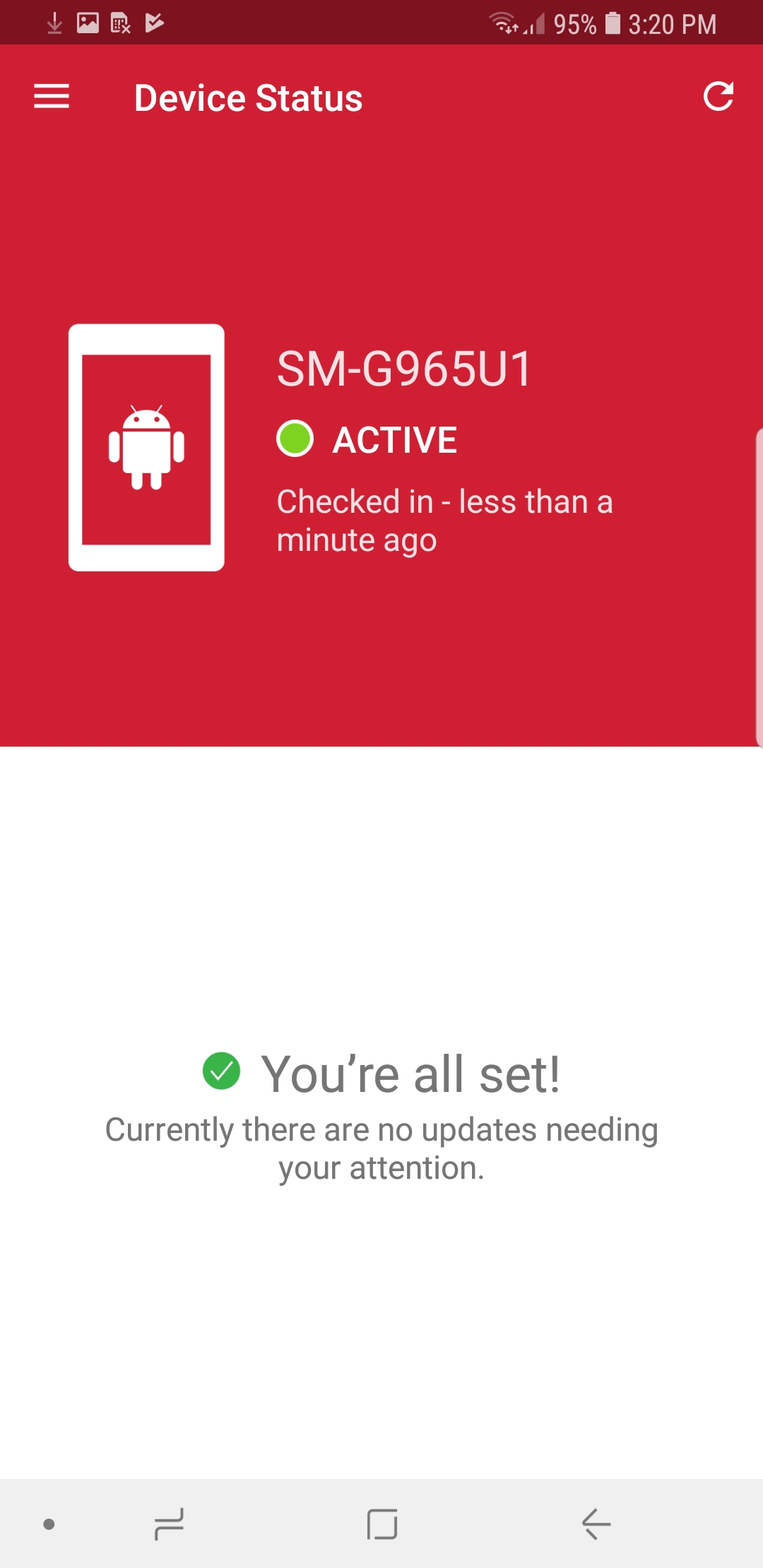
Figure 2‑175 MobileIron Device Status
Figure 2‑176 AFW Configuration
Figure 2‑177 AFW Workspace Creation
Figure 2‑178 MobileIron Work Profile Lock Preferences
Figure 2‑179 MobileIron Google Account Configuration
Figure 2‑180 MobileIron Device Status
List of Tables
Table 1‑1 Typographic Conventions
Table 2‑1 Implemented Security Policies
Table 2‑2 Implemented Security Policies
Table 2‑3 Implemented Security Policies
1 Introduction
The following volumes of this guide show information technology (IT) professionals and security engineers how we implemented this example solution. We cover all of the mobile device security products employed in this reference design. We do not re-create the product manufacturers’ documentation, which is presumed to be widely available. Rather, these volumes show how we incorporated the products together in our environment.
Note: These are not comprehensive tutorials. There are many possible service and security configurations for these products that are out of scope for this reference design.
1.1 Practice Guide Structure
This National Institute of Standards and Technology (NIST) Cybersecurity Practice Guide demonstrates a standards-based reference design and provides users with the information they need to replicate addressing mobile device security (MDS) for Corporate-Owned Personally-Enabled (COPE) implementation challenges. This reference design is modular and can be deployed in whole or in part.
This guide contains three volumes:
NIST SP 1800-21A: Executive Summary
NIST SP 1800-21B: Approach, Architecture, and Security Characteristics – what we built and why
NIST SP 1800-21C: How-To Guides – instructions for building the example solution (you are here)
Depending on your role in your organization, you might use this guide in different ways:
Business decision makers, including chief security and technology officers, will be interested in the Executive Summary, NIST SP 1800-21A, which describes the following topics:
challenges that enterprises face in securely deploying COPE mobile devices
example solution built at the National Cybersecurity Center of Excellence (NCCoE)
benefits of adopting the example solution
Technology or security program managers who are concerned with how to identify, understand, assess, and mitigate risk will be interested in NIST SP 1800-21B, which describes what we did and why. The following sections will be of particular interest:
Section 3.4, Risk Assessment, describes the risk analysis we performed.
Section 4.3, Security Control Map, discusses the security mappings of this example solution to cybersecurity standards and best practices.
You might share the Executive Summary, NIST SP 1800-21A, with your leadership team members to help them understand the importance of adopting standards-based solutions when addressing COPE mobile device security implementation challenges.
IT professionals who want to implement an approach like this will find this whole practice guide useful. You can use this How-To portion of the guide, NIST SP 1800-21C, to replicate all or parts of the build created in our lab. This How-To portion of the guide provides specific product installation, configuration, and integration instructions for implementing the example solution. We do not recreate the product manufacturers’ documentation, which is generally widely available. Rather, we show how we incorporated the products together in our environment to create an example solution.
This guide assumes that IT professionals have experience implementing security products within the enterprise. While we have used a suite of commercial products to address this challenge, this guide does not endorse these particular products. Your organization can adopt this solution or one that adheres to these guidelines in whole, or you can use this guide as a starting point for tailoring and implementing parts of this guide’s example solution for on-premises mobile device security management. Your organization’s security experts should identify the products that will best integrate with your existing tools and IT system infrastructure. We hope that you will seek products that are congruent with applicable standards and best practices. Section 3.6, Technologies, lists the products that we used and maps them to the cybersecurity controls provided by this reference solution.
A NIST Cybersecurity Practice Guide does not describe “the” solution, but a possible solution. Comments, suggestions, and success stories will improve subsequent versions of this guide. Please contribute your thoughts to mobile-nccoe@nist.gov.
1.2 Build Overview
When a business is on the go, mobile devices can serve as a temporary workstation replacement. They provide convenience of use, portability, and functionality. However, in many ways, mobile devices are different from the common computer workstation, and alternative management tools are required to secure their interactions with the enterprise. To address this security challenge, the NCCoE worked with its Community of Interest and build team partners and developed a real-world scenario for mobile deployment within an enterprise. The scenario presents a range of security challenges that an enterprise may experience when deploying mobile devices.
The lab environment used in developing this solution includes the architectural components, functionality, and standard best practices, which are described in Volume B. The build team partners provided the security technologies used to deploy the architecture components and functionality. The standard best practices are applied to the security technologies to ensure the appropriate security controls are put in place to meet the challenges presented in the devised scenario.
This section of the guide documents the build process and discusses the specific configurations used to develop a secure mobile deployment.
Note: Android for Work (AFW) has been re-branded as Android Enterprise. At the time of writing this document, it was named Android for Work.
1.3 Typographic Conventions
The following table presents typographic conventions used in this volume.
Table 1-1 Typographic Conventions
Typeface/ Symbol |
Meaning |
Example |
|---|---|---|
Italics |
file names and path names; references to documents that are not hyperlinks; new terms; and placeholders |
For language use and style guidance, see the NCCoE Style Guide. |
Bold |
names of menus, options, command buttons, and fields |
Choose File > Edit. |
|
command-line input, onscreen computer output, sample code examples, and status codes |
|
|
command-line user input contrasted with computer output |
|
link to other parts of the document, a web URL, or an email address |
All publications from NIST’s NCCoE are available at https://www.nccoe.nist.gov. |
1.4 Logical Architecture Summary
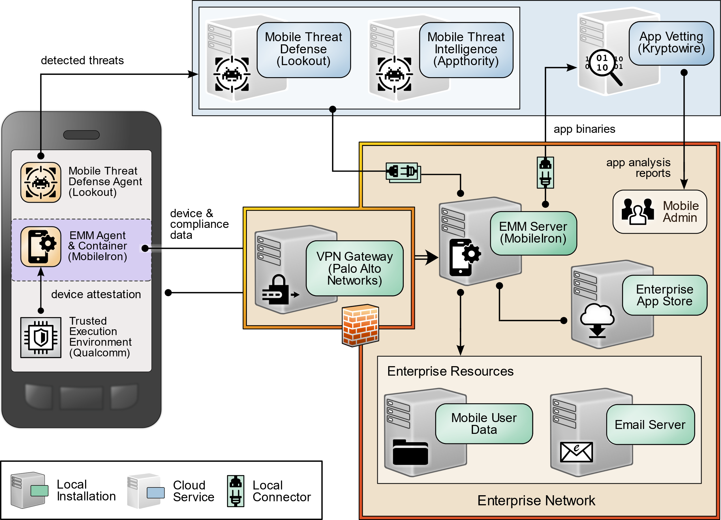
The following graphic illustrates the main components of this example implementation and provides a view of how they interact.
Figure 1‑1 Logical Architecture Summary
2 Product Installation Guides
This section of the practice guide contains detailed instructions for installing and configuring key products used for the architecture illustrated below.
In our lab environment, the example solution was logically separated by a virtual local area network (VLAN) wherein each VLAN represented a separate mock enterprise environment. The network perimeter for this example implementation was enforced by a Palo Alto Networks virtual private network (VPN)/firewall appliance. It maintains three zones: one each for the internet/wide area network (WAN), a demilitarized zone (DMZ), and the organizational local area network (LAN).
2.1 Appthority Mobile Threat Detection
Appthority contributed a test instance of its Mobile Threat Detection service. Contact Appthority (Symantec) (https://www.symantec.com/) to establish an instance for your organization.
2.2 Kryptowire EMM+S
Kryptowire contributed a test instance of its EMM+S application-vetting service. Contact Kryptowire (https://www.kryptowire.com/mobile-app-security/) to establish an instance for your organization.
2.3 Lookout Mobile Endpoint Security
Lookout contributed a test instance of its Mobile Endpoint Security (MES) service. Contact Lookout (https://www.lookout.com/products/mobile-endpoint-security) to establish an instance for your organization.
2.4 MobileIron Core
MobileIron Core is the central product in the MobileIron suite. The following sections describe the steps for installation, configuration, and integration with Active Directory (AD).
2.4.1 Installation of MobileIron Core and Stand-Alone Sentry
Follow the steps below to install MobileIron Core:
Obtain a copy of the On-Premise Installation Guide for MobileIron Core, Sentry, and Enterprise Connector from the MobileIron support portal.
Follow the MobileIron Core pre-deployment and installation steps in Chapter 1 of the On-Premise Installation Guide for MobileIron Core, Sentry, and Enterprise Connector for the version of MobileIron being deployed in your environment. In our lab implementation, we deployed MobileIron Core 9.5.0.0 as a Virtual Core running on VMware 6.0. Post-installation, we performed an upgrade to MobileIron Core 9.7.0.1 following guidance provided in CoreConnectorReleaseNotes9701_Rev12Apr2018. Direct installations to MobileIron Core 9.7.0.1 will experience slightly different results, as some added features in this version are not used with earlier versions of configuration files.
2.4.2 General MobileIron Core Setup
The following steps are necessary for mobile device administrators or users to register devices with MobileIron.
Obtain a copy of MobileIron Core Device Management Guide for iOS Devices from the MobileIron support portal.
Complete all instructions provided in Chapter 1, Setup Tasks.
2.4.3 Upgrade MobileIron Core
The following steps were used to upgrade our instance of MobileIron Core from 9.5.0.0 to 9.7.0.1. Note there was no direct upgrade path between these two versions; our selected upgrade path was 9.5.0.0 > 9.5.0.1 > 9.7.0.1.
Obtain upgrade credentials from MobileIron Support.
In MobileIron Core System Manager, navigate to Maintenance > Software Updates.
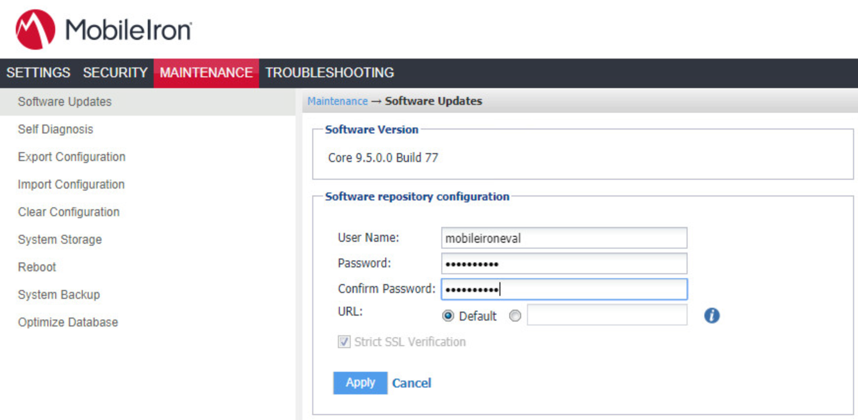
In the Software repository configuration section:
In the User Name field, enter the username provided by MobileIron Support.
In the Password field, enter the password provided by MobileIron Support.
In the Confirm Password field, reenter the password provided by MobileIron Support.
Select Apply.
Figure 2‑1 MobileIron Repository Configuration
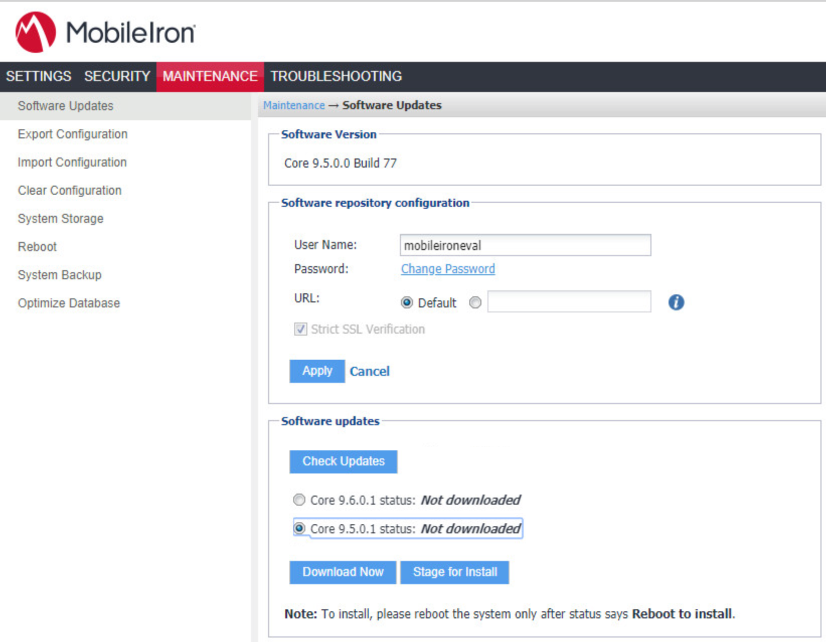
In the Software Updates section:
Select Check Updates; after a few seconds, the available upgrade path options appears.
Select the Core 9.5.0.1 status: Not Downloaded option.
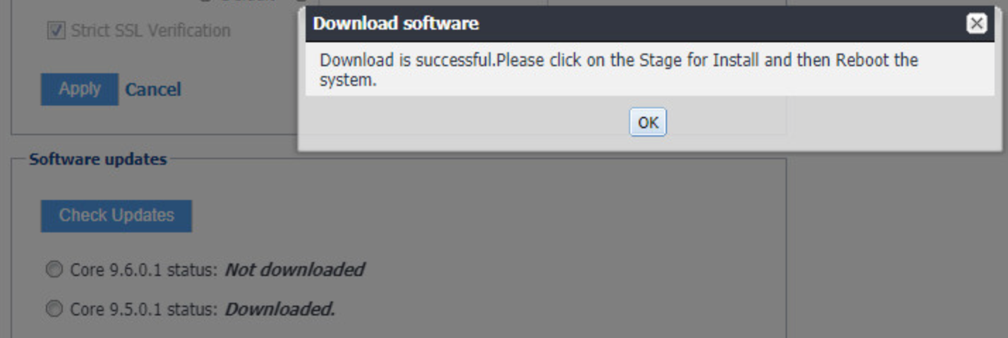
Select Download Now. After a delay, the Software Download dialogue appears.
Figure 2‑2 MobileIron Core Version
In the Download Software dialogue, click OK.
Figure 2‑3 MobileIron Download Status
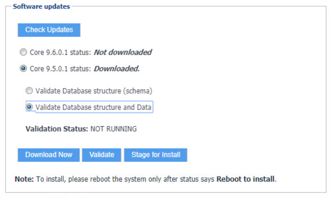
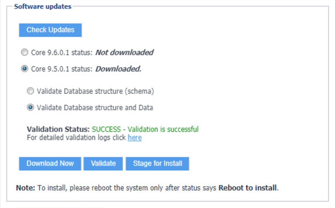
In the Software updates section:
Select the Core 9.5.0.1 status: Downloaded option.
Select the Validate Database Structure and Data option.
Select Validate.
Figure 2‑4 Validating Database Data
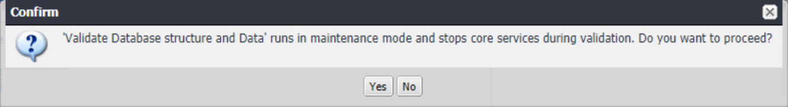
In the Confirm dialogue, click Yes to validate database structure and data.
Figure 2‑5 Validating Database Data Confirmation
In the Validate Update dialogue, click OK.
Figure 2‑6 Database Data Validation Initiation Confirmation
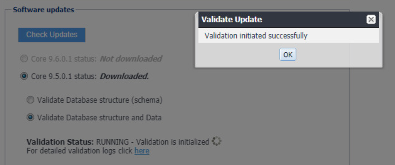
In the Software updates section, select Stage for Install.
Figure 2‑7 Database Data Validation Status
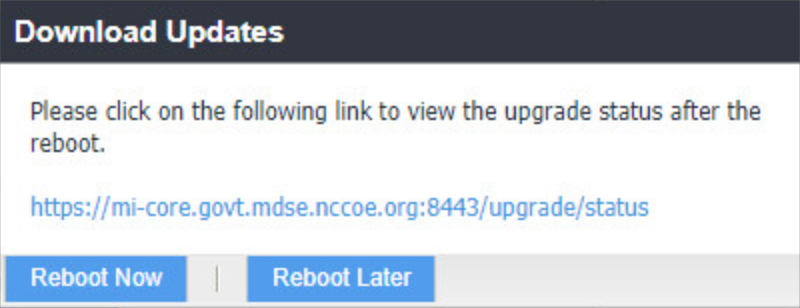
The Download Updates dialogue appears.
In the Download Updates dialogue, select Reboot Now; a series of dialogues appears.
Figure 2‑8 Software Updates Reboot Prompt
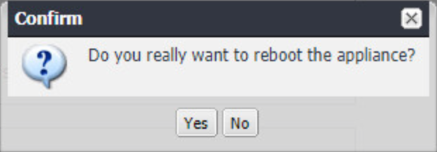
In the Confirm dialogues:
Click Yes to confirm the appliance reboot.
Figure 2‑9 Software Update Reboot Confirmation
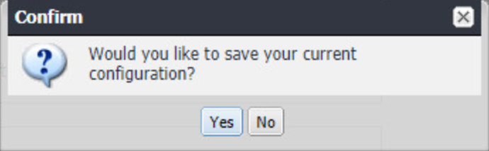
Click Yes to confirm saving the current configuration.
Figure 2‑10 Reboot Configuration Save Prompt
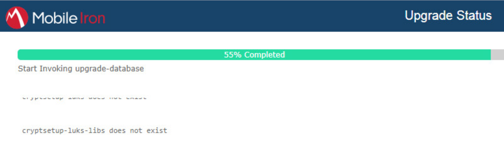
The Upgrade Status website hosted by Core automatically opens.
Figure 2‑11 Upgrade Status
Once the upgrade is complete, System Manager > Maintenance > Software Updates > Software Updates now shows the capability to upgrade to 9.7.0.1.
Figure 2‑12 Ability to Upgrade to 9.7.0.1
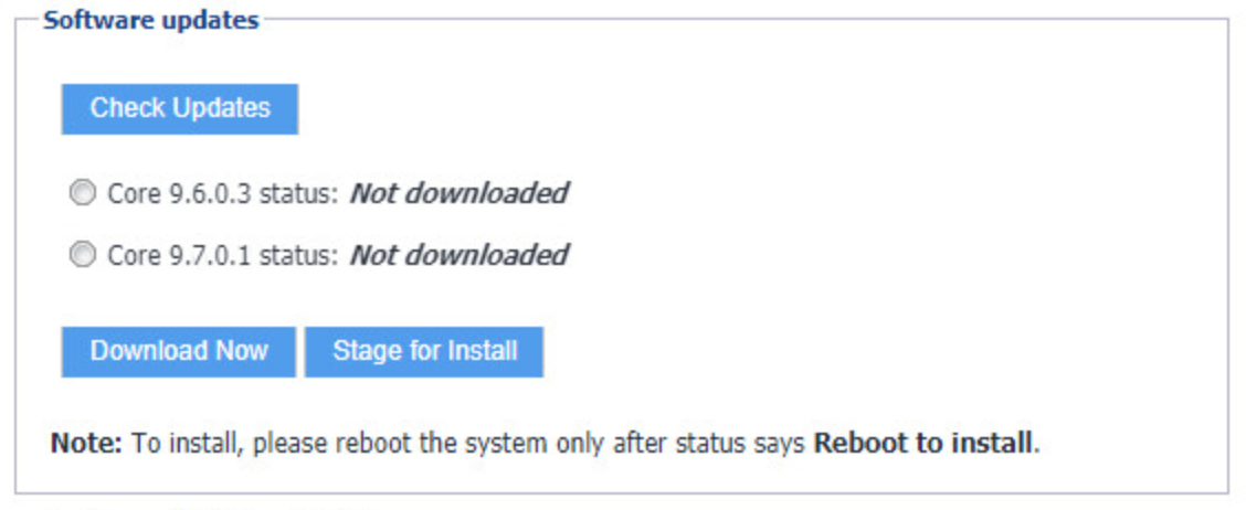
The image shows the Core patch levels this instance can upgrade to. Specifically, it shows Core 9.6.0.3 and Core 9.7.0.1.
Repeat Steps 4b through 11 above, replacing 9.5.0.1 with 9.7.0.1 during Steps 4b and 6; this will complete the upgrade path from MobileIron Core 9.5.0.0 to 9.7.0.1.
2.4.4 Integration with Microsoft Active Directory
In our implementation, we chose to integrate MobileIron Core with Active Directory using lightweight directory access protocol (LDAP). This is optional. General instructions for this process are covered in the Configuring LDAP Servers section in Chapter 2 of On-Premise Installation Guide for MobileIron Core, Sentry, and Enterprise Connector. The configuration details used during our completion of selected steps (retaining the original numbering) from that guide are given below:
From Step 4 in the MobileIron guide, in the New LDAP Server dialogue:
Directory Connection:
Figure 2‑13 LDAP Settings
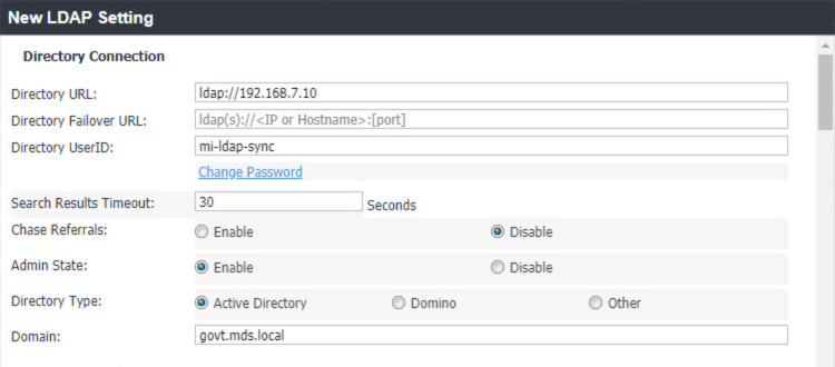
Note: The light gray text is default text, and your own directory URL should be entered.
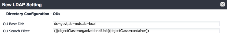
Directory Configuration—OUs (organizational units):
Figure 2‑14 LDAP OUs
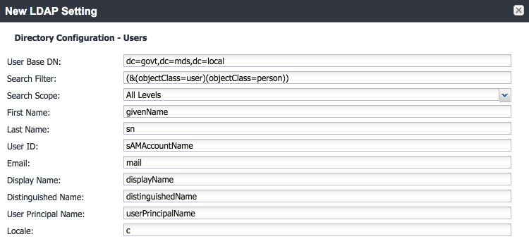
Directory Configuration—Users:
Figure 2‑15 LDAP User Configuration
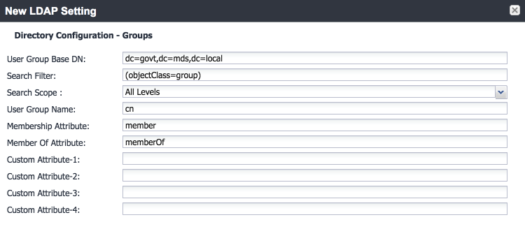
Directory Configuration—Groups:
Figure 2‑16 LDAP Group Configuration
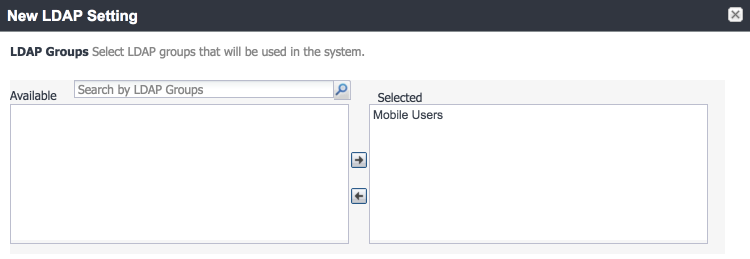
LDAP Groups:
As a preparatory step, we used Active Directory Users and Computers to create a new security group for mobile-authorized users on the Domain Controller for the govt.mds.local domain. In our example, this group is named Mobile Users.
In the search bar, enter the name of the LDAP group for mobile-authorized users.
Select the magnifying glass button; the group name should be added to the Available list.
In the Available list box:
1. Select the Mobile Users list item.
2. Select the right-arrow button; the Mobile Users list item should move to the Selected list box.
Figure 2‑17 Selected LDAP Group
In the Selected list:
1. Select the default Users group list item.
2. Select the left-arrow button; the Users list item should move to the Available list box.
Custom Settings: Custom settings were not specified.
Advanced Options: Advanced options were configured as shown in Figure 2‑18.
Figure 2‑18 LDAP Advanced Options
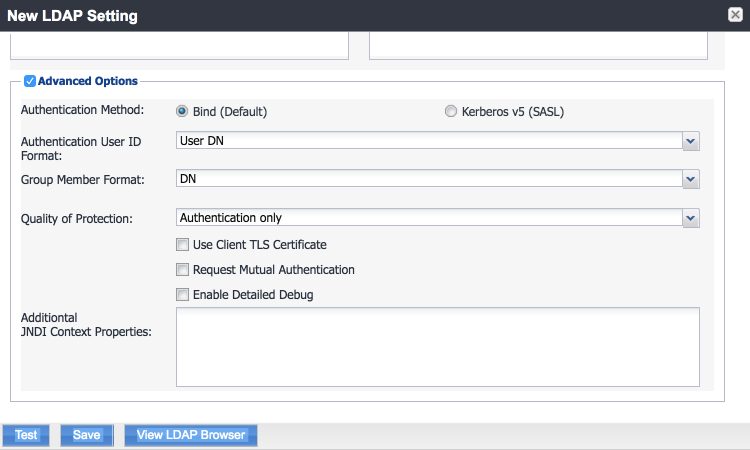
Note: In our lab environment, we did not enable stronger Quality of Protection or enable the Use of Client Transport Layer Security Certificate or Request Mutual Authentication features. However, we recommend that implementers consider using those additional mechanisms to secure communication with the LDAP server.
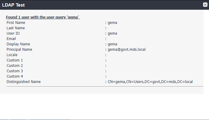
From Steps 19 through 21 from the MobileIron guide, we tested that MobileIron can successfully query LDAP for Derived Personal Identity Verification Credential (DPC) Users.
In the New LDAP Setting dialogue, click the Test button to open the LDAP Test dialogue.
In the LDAP Test dialogue, enter a User ID for a member of the DPC Users group, then click the Submit button. A member of the Mobile Users group in our environment is gema.
Figure 2‑19 Testing LDAP Configuration

The LDAP Test dialogue indicates the query was successful:
Figure 2‑20 LDAP Test Result
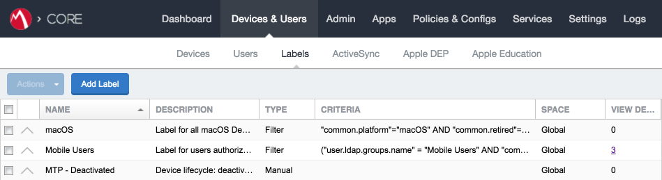
2.4.5 Create a Mobile Users Label
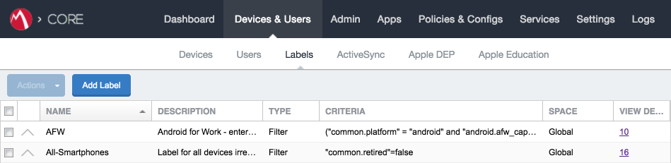
MobileIron uses labels to link policies and device configurations with users and mobile devices. Creating a unique label for each category of authorized mobile user allows mobile device administrators to apply a consistent set of controls applicable to users with a common mobile use case. Our limited usage scenario only required a single MobileIron label to be created.
In the MobileIron Core Admin Portal, navigate to Devices & Users > Labels.
Select Add Label.
Figure 2‑21 MobileIron Device Labels
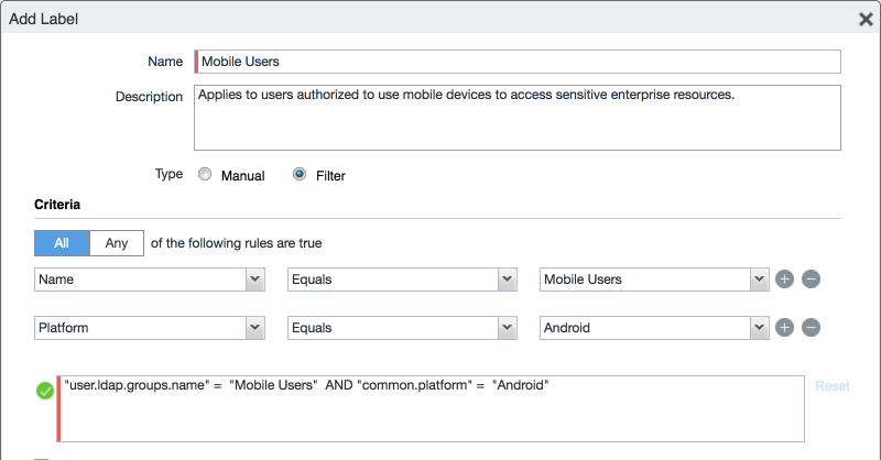
In the Name field, enter a unique name for this label (Mobile Users in this example).
In the Description field, enter a meaningful description to help others identify its purpose.
Under the Criteria section:
In the blank rule:
In the Field drop-down menu, select User > LDAP > Groups > Name.
In the Value drop-down menu, select the Active Directory group created to support mobile user policies (named Mobile User in this example).
Select the plus sign icon to add a blank rule.
In the newly created blank rule:
In the Field drop-down menu, select Common > Platform.
In the Value drop-down menu, select Android.
Figure 2‑22 Adding a Device Label
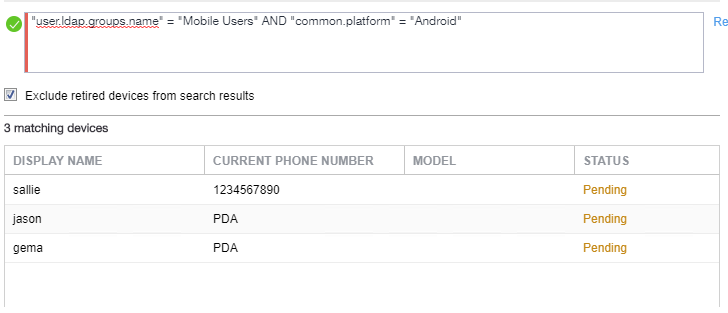
The list of matching devices appears below the specified criteria.
Select Save.
Figure 2‑23 Device Label Matches
Navigate to Devices & Users > Labels to confirm the label was successfully created.
Figure 2‑24 MobileIron Label List
2.5 Integration of Palo Alto Networks GlobalProtect with MobileIron
The following steps detail how to integrate MobileIron Core, Microsoft Certificate Authority (CA), and Palo Alto Networks GlobalProtect to allow mobile users to authenticate to the GlobalProtect gateway using user-aware device certificates issued to mobile devices by Microsoft CA during enrollment with MobileIron Core.
2.5.1 MobileIron Configuration
The following steps create the MobileIron Core configurations necessary to support integration with Palo Alto Networks GlobalProtect and Microsoft CA.
2.5.1.1 Create Simple Certificate Enrollment Protocol (SCEP) Configuration
In the MobileIron Admin Portal, navigate to Policies & Configs > Configurations.
Select Add New > Certificate Enrollment > SCEP; the New SCEP Configuration Enrollment Setting dialogue will open.
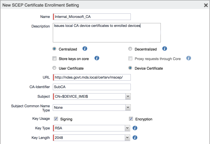
In the New SCEP Certificate Enrollment Setting dialogue:
For the Name field, enter a unique name to identify this configuration.
Enable the Device Certificate option.
In the URL field, enter the URL where SCEP is hosted within your environment.
In the CA-Identifier (ID) field, enter the subject name of the Microsoft CA that will issue the device certificates.
In the Subject drop-down menu, select $DEVICE_IMEI$.
Figure 2‑25 MobileIron SCEP Configuration
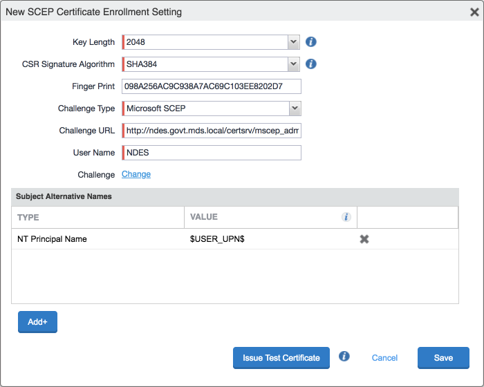
In the Fingerprint field, enter the fingerprint of the Microsoft CA that will issue the device certificates.
For the Challenge Type drop-down menu, select Microsoft SCEP.
Below the Subject Alternative Names list box, select Add; a new list item appears.
For the new list item:
i. For the Type drop-down menu, select NT Principal Name.
ii. For the Value drop-down menu, select $USER_UPN$.
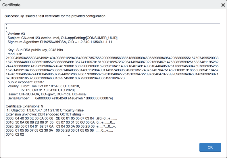
Click Issue Test Certificate; the Certificate dialogue should indicate success.
Figure 2‑26 Test SCEP Certificate Configuration
In the Certificate dialogue, click OK.
Figure 2‑27 Test SCEP Certificate
Click Save.
2.5.1.2 Create Palo Alto Networks GlobalProtect Configuration
The GlobalProtect configuration instructs the mobile client to use the provisioned device certificate and to automatically connect to the correct VPN URL; mobile users will not need to manually configure the application. The following steps will create the GlobalProtect configuration.
In the MobileIron Admin Portal, navigate to Policies & Configs > Configurations.
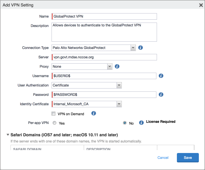
Select Add New > VPN; the Add VPN Setting dialogue will appear.
In the Add VPN Setting dialogue:
In the Name field, enter a unique name to identify this VPN setting.
In the Connection Type drop-down menu, select Palo Alto Networks GlobalProtect.
In the Server field, enter the fully qualified domain name (FQDN) of your Palo Alto Networks appliance; our sample implementation uses vpn.govt.mdse.nccoe.org.
For the User Authentication drop-down menu, select certificate.
For the Identity Certificate drop-down menu, select the SCEP enrollment profile created in the previous section.
Click Save.
Figure 2‑28 MobileIron VPN Configuration
2.5.2 Basic Palo Alto Networks Configuration
During basic configuration, internet protocol (IP) addresses are assigned to the management interface, domain name system (DNS), and network time protocol (NTP). The management interface allows the administrator to configure and implement security rules through this interface.
2.5.2.1 Configure Management Interface
The following steps will configure the Palo Alto Networks appliance management interface.
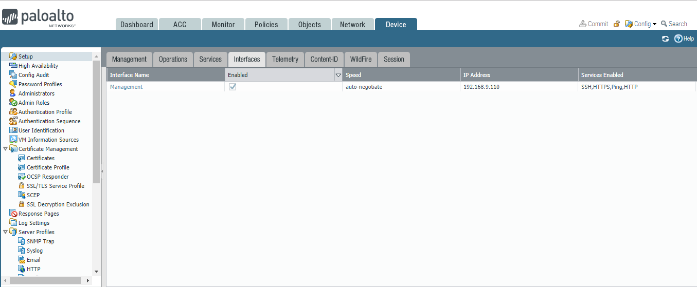
In the Palo Alto Networks portal, navigate to Device > Setup > Interfaces.
On the Interfaces tab, enable the Management option; the Management Interface Setting page opens.
Figure 2‑29 Palo Alto Networks Management Interface Enabled
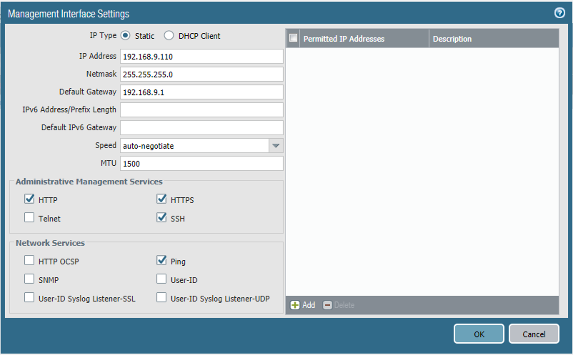
On the Management Interface Setting screen:
In the IP Address field, enter the IP address for the Palo Alto Networks appliance.
In the Netmask field, enter the netmask for the network.
In the Default Gateway field, enter the IP address of the router that provides the appliance with access to the internet.
Under Administrative Management Services: Enable the Hypertext Transfer Protocol (HTTP), Hypertext Transfer Protocol Secure (HTTPS), Secure Shell (SSH), and Ping options.
Click OK.
Figure 2‑30 Management Interface Configuration
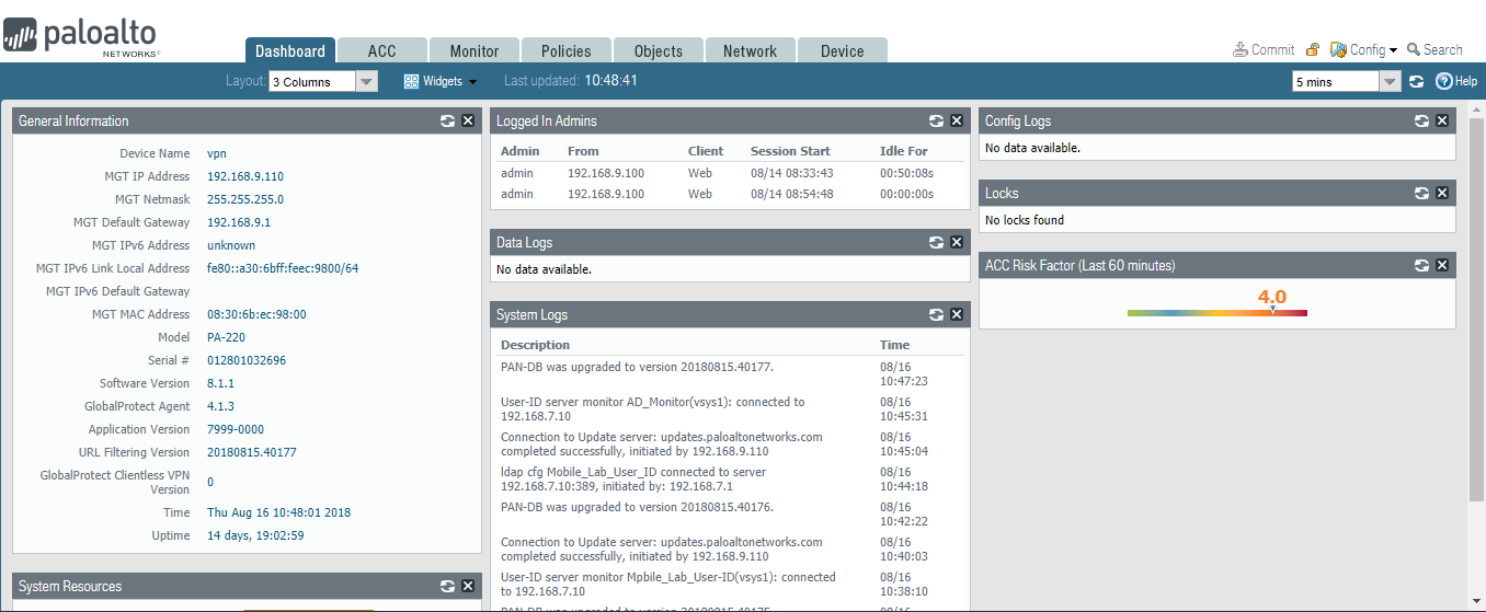
To verify the configuration, navigate to Palo Alto Networks Portal > Dashboard; the General Information section should reflect the appliance’s network configuration.
Figure 2‑31 Palo Alto Networks Firewall General Information
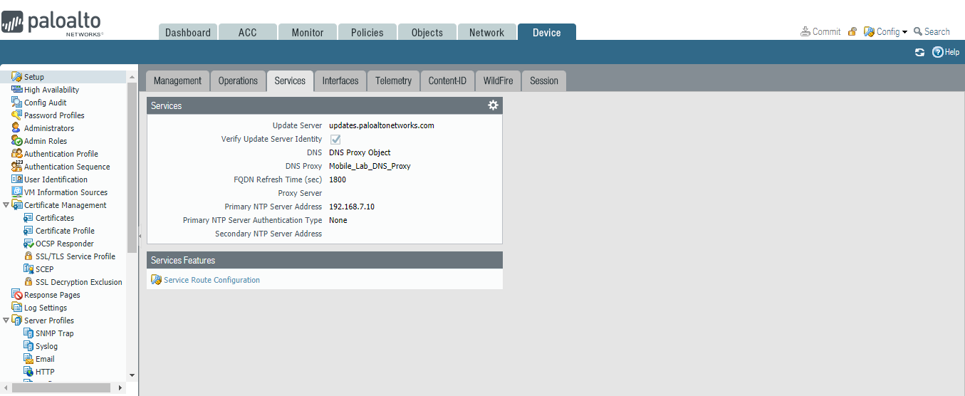
2.5.2.2 Configure DNS and NTP
In the Palo Alto Networks Portal, navigate to Device > Setup > Services.
In the Services tab, select the gear icon.
Figure 2‑32 Palo Alto Networks Services Configuration
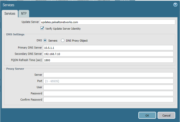
On the Services > Services tab:
For the Primary DNS Server field, enter the primary DNS server IP address.
For the Secondary DNS Server field, enter the secondary DNS server IP address, if applicable.
Select the NTP tab.
Figure 2‑33 DNS Configuration
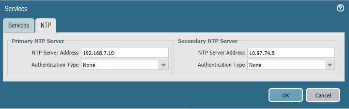
On the NTP tab:
For the Primary NTP Server > NTP Server Address field, enter the IP address of the primary NTP server to use.
For the Secondary NTP Server > NTP Server Address field, enter the IP address of the backup NTP server to use, if applicable.
Click OK.
Figure 2‑34 NTP Configuration
2.5.3 Palo Alto Networks Interfaces and Zones Configuration
Palo Alto Networks firewall model PA-220 has eight interfaces that can be configured as trusted (inside) or untrusted (outside) interfaces. This section describes creating a zone and assigning an interface to it.
2.5.3.1 Create Ethernet Interfaces and Addresses
Our example implementation uses three interfaces:
LAN: Orviliaʼs LAN, which hosts intranet web and mail services
DMZ: Orviliaʼs DMZ network subnet, which hosts MobileIron Core and MobileIron Sentry
WAN: provides access to the internet and is the inbound interface for secure sockets layer (SSL) VPN connections
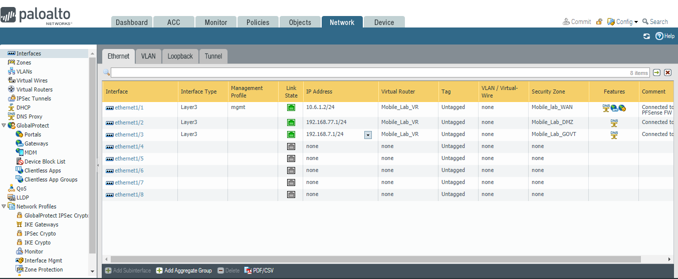
To create and configure Ethernet interfaces:
Navigate to Palo Alto Networks Portal > Network > Ethernet > Interfaces > Ethernet.
Figure 2‑35 Ethernet Interfaces
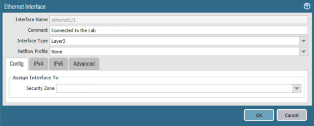
In the Ethernet tab, select the name of the interface to configure; the Ethernet Interface dialogue will appear.
In the Ethernet Interface dialogue:
In the Comment field, enter a description for this interface.
For the Interface Type drop-down menu, select Layer3.
Figure 2‑36 Ethernet Interface Configuration
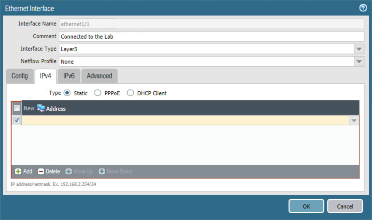
Select the IPv4 tab.
On the IPv4 tab:
In the IP list box, select Add; a blank list item appears.
In the blank list item, select New Address; the Address dialogue appears.
Figure 2‑37 WAN Interface IPv4 Configuration
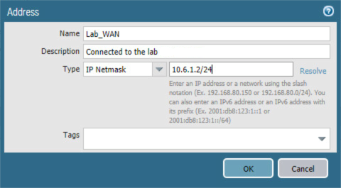
In the Address dialogue:
1. For the Name field, enter a unique name to identify this address.
2. For the Description field, enter a meaningful description of the purpose of this address.
3. In the unnamed field following the Type drop-down menu, enter the IPv4 address that this interface will use in Classless Inter-Domain Routing notation. This example uses 10.6.1.2/24 for the WAN interface in our lab environment.
4. Click OK.
Figure 2‑38 WAN Interface IP Address Configuration
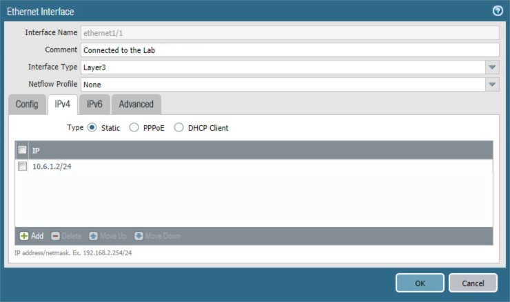
The address should now appear as an item in the IP list box; select OK; the Address dialogue closes.
Figure 2‑39 Completed WAN Interface Configuration
Click OK.
Repeat Steps 2 and 3 for each of the additional Ethernet/Layer3 interfaces.
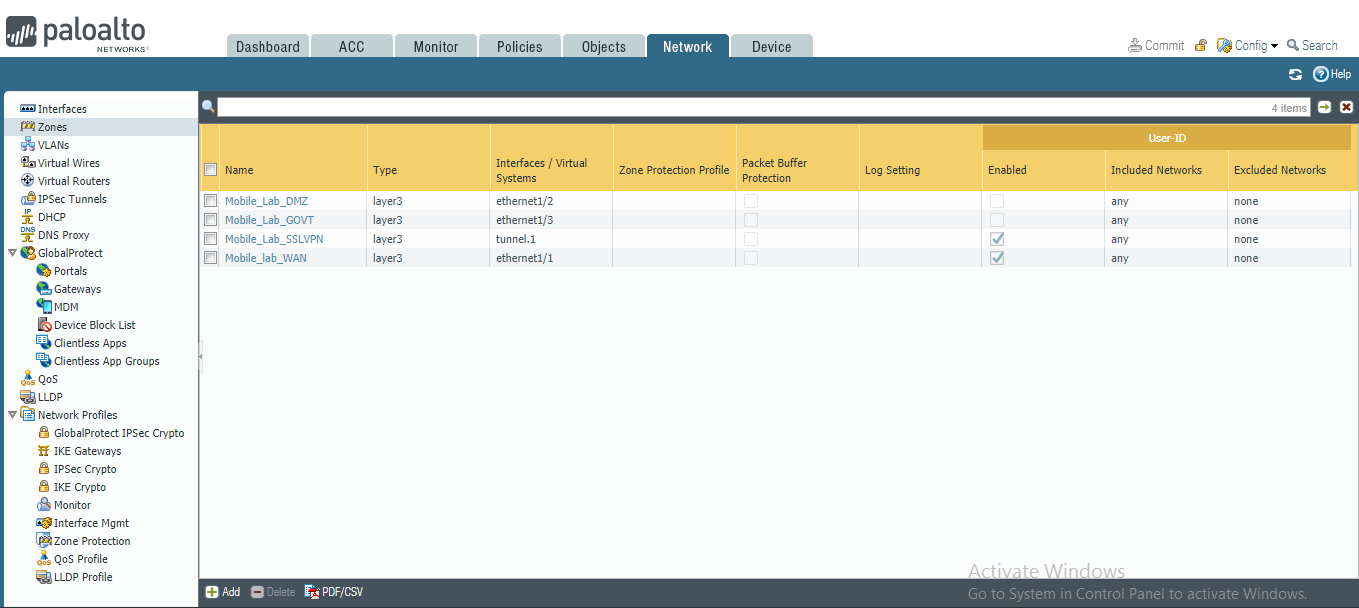
2.5.3.2 Create Security Zones
The PA Security Zone is a collection of single or multiple interfaces that have the same security rules. For this setup, four different zones have been configured:
Mobile_Lab_GOVT: inside (trusted) interface connecting to the government (GOVT) segment
Mobile_Lab_DMZ: inside (trusted) interface connecting to the DMZ segment
Mobile_Lab_WAN: outside (untrusted) interface to permit trusted inbound connections (e.g., Lookout cloud service) from the untrusted internet and allow internet access to on-premises devices
Mobile_Lab_SSLVPN: outside (untrusted) interface for VPN connections by trusted mobile devices originating from untrusted networks (e.g., public Wi-Fi)
To configure each zone:
Navigate to Palo Alto Networks Portal > Network > Zones.
Figure 2‑40 Security Zone List
In the Zones pane, select Add; the Zones page opens.
On the Zones page:
For the Name field, provide a unique name for the zone.
For the Type drop-down menu, select Layer 3.
Under Interfaces, select Add; a blank drop-down menu appears.
In the drop-down menu, select the interface to assign to this zone; this example shows selection of ethernet 1/3, which is associated with the LAN interface.
Click OK.
Figure 2‑41 LAN Security Zone Configuration
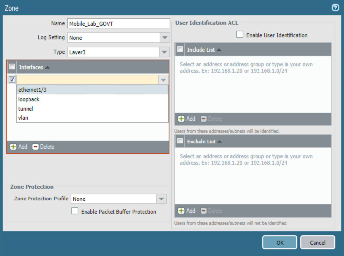
Repeat Step b for each zone.
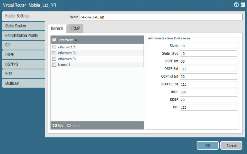
2.5.4 Configure Router
Palo Alto Networks uses a virtual router to emulate physical connectivity between interfaces in different zones. To permit systems to reach systems in other zones, the following steps will create a virtual router and add interfaces to it. The router also sets which of these interfaces will act as the local gateway to the internet.
In the Palo Alto Networks Portal, navigate to Network > Virtual Routers.
Below the details pane, select Add; the Virtual Router form opens.
In the Virtual Router form, on the Router Settings tab:
For the Name field, enter a unique name to identify this router.
On the Router Settings > General tab:
Under the Interfaces list box, select Add; a new list item appears.
In the new list item drop-down menu, select an existing interface.
Repeat Steps 3a and 3b to add all existing interfaces to this router.
Select the Static Routes tab.
On the Static Routes > IPv4 tab:
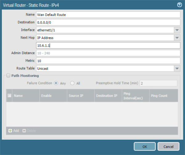
Below the list box, select Add; the Virtual Router - Static Route - IPv4 form opens.
In the Virtual Router—Static Route—IPv4 form:
For the Name field, enter a unique name to identify this route.
For the Destination field, enter 0.0.0.0/0.
For the Interface drop-down menu, select the interface that provides access to the internet.
For the Next Hop drop-down menu, select IP Address.
In the field below Next Hop, enter the IP address of the gateway that provides access to the internet.
Click OK.
Figure 2‑42 Virtual Router Configuration
Click OK.
Figure 2‑43 Virtual Router General Settings
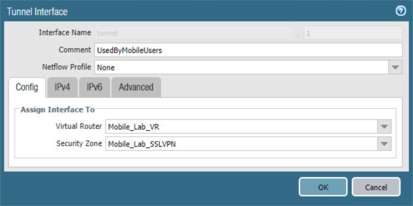
2.5.5 Configure Tunnel Interface
The SSL VPN uses a tunnel interface to secure traffic from the external zone to the internal zone where organizational resources available to mobile users are maintained. To configure the tunnel interface:
Navigate to Palo Alto Networks Portal > Network > Ethernet > Interfaces > Tunnel.
Below the details pane, select Add; the Tunnel Interface form opens.
In the Tunnel Interface form on the Config tab:
In the Assign Interface To section:
For the Virtual Router drop-down menu, select the virtual router created in the previous section.
For the Security Zone drop-down menu, select the security zone created for the SSL VPN.
Click OK.
Figure 2‑44 SSL VPN Tunnel Interface
2.5.6 Configure Applications and Security Policies
Security policies work similarly to firewall rules; they block or allow traffic between defined zones identified by a source, destination, and application(s) (contextually, Palo Alto Networks’ objects define network protocols and ports). Palo Alto Networks has built-in applications for a large number of standard and well-known protocols and ports (e.g., LDAP and Secure Shell), but we defined custom applications for MobileIron-specific traffic.
2.5.6.1 Configure Applications
The following steps will create an application:
In the Palo Alto Networks Portal, navigate to Objects > Applications.
Figure 2‑45 Application Categories
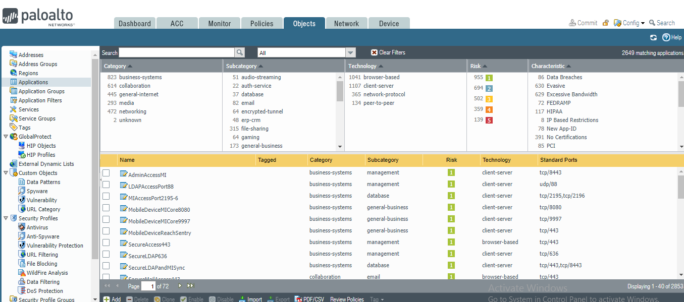
On the Applications screen:
Select Add; the Application form opens.
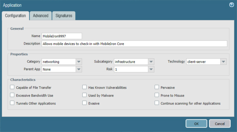
On the Application > Configuration screen:
In the General > Name field, provide a unique name to identify this application.
In the General > Description field, enter a meaningful description of its purpose.
For the Properties > Category drop-down menu, select a category appropriate to your environment; our sample implementation uses networking.
For the Properties > Subcategory drop-down menu, select a subcategory appropriate to your environment; our sample implementation uses infrastructure.
For the Properties > Technology drop-down menu, select a technology appropriate to your environment; our sample implementation uses client-server.
Figure 2‑46 MobileIron Core Palo Alto Networks Application Configuration
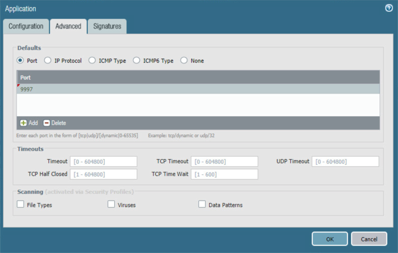
Select the Advanced tab.
On the Application > Advanced screen:
Select Defaults > Port.
Under the Ports list box, select Add; a blank list item appears.
In the blank list item, enter the port number used by the application; this example uses 9997.
Click OK.
Figure 2‑47 MobileIron Application Port Configuration
Repeat Steps 2 through 7 with the following modifications to create an application for the MobileIron Core system administration console:
Configuration > General > Name is MobileIron8443.
Configuration > Properties > Category is business-systems.
Configuration > Properties > Subcategory is management.
Advanced > Defaults > Port first entry is 8443.
2.5.6.2 Configure Security Policies
Security policies allow or explicitly deny communication within, between, or (externally) to or from Palo Alto Networks zones. For this sample implementation, several security policies were created to support communication by other components of the architecture. The first subsection covers the steps to create a given security policy. The second subsection provides a table illustrating the security policies we used; these policies would need to be adapted to host names and IP addresses specific to your network infrastructure.
2.5.6.2.1 Create Security Policies
To create a security policy:
In the Palo Alto Networks Portal, navigate to Policies > Security.
Select Add; the Security Policy Rule form will open.
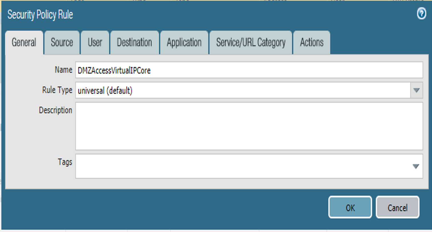
In the Security Policy Rule form:
In the Name field, enter a unique name for this security rule.
For the Rule Type drop-down menu, select the scope of the rule, following the guidance provided in the Palo Alto Networks documentation for creating firewall rules.
Figure 2‑48 DMZ Access to MobileIron Firewall Rule Configuration
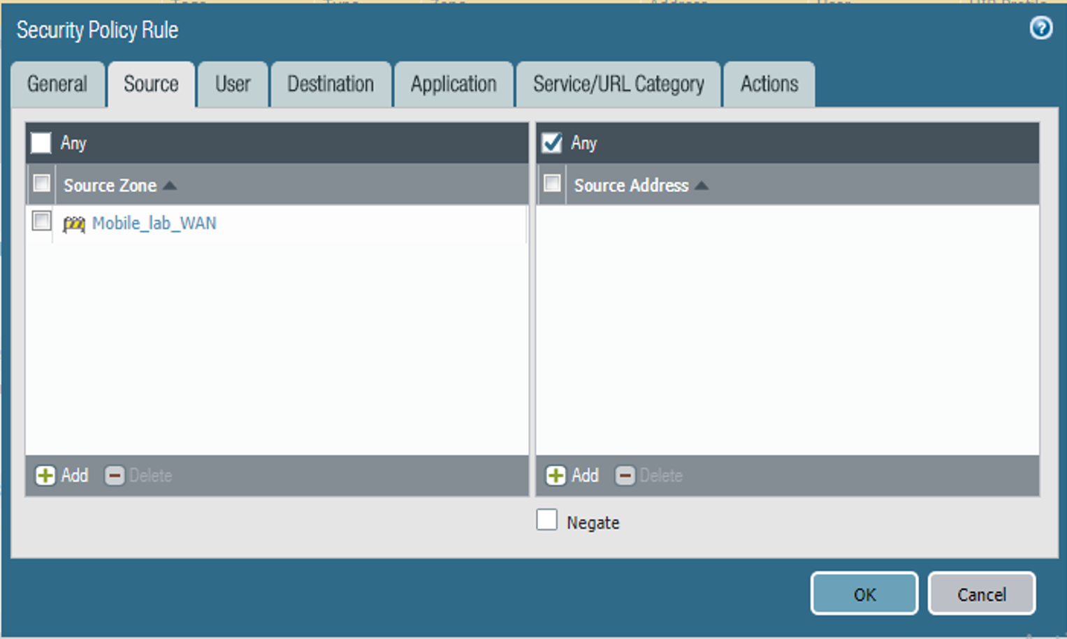
Select the Source tab.
On the Source tab:
If the security rule applies to a specific source zone:
Under the Source Zone list box, select Add; a new entry appears in the list box.
For the new list item, select the source zone for this rule.
If the rule applies to only specific source IP addresses:
Under the Source Address list box, select Add; a new list item appears.
For the new list item, select the source address for this rule.
Figure 2‑49 DMZ Access to MobileIron Security Rule Source Zone Configuration
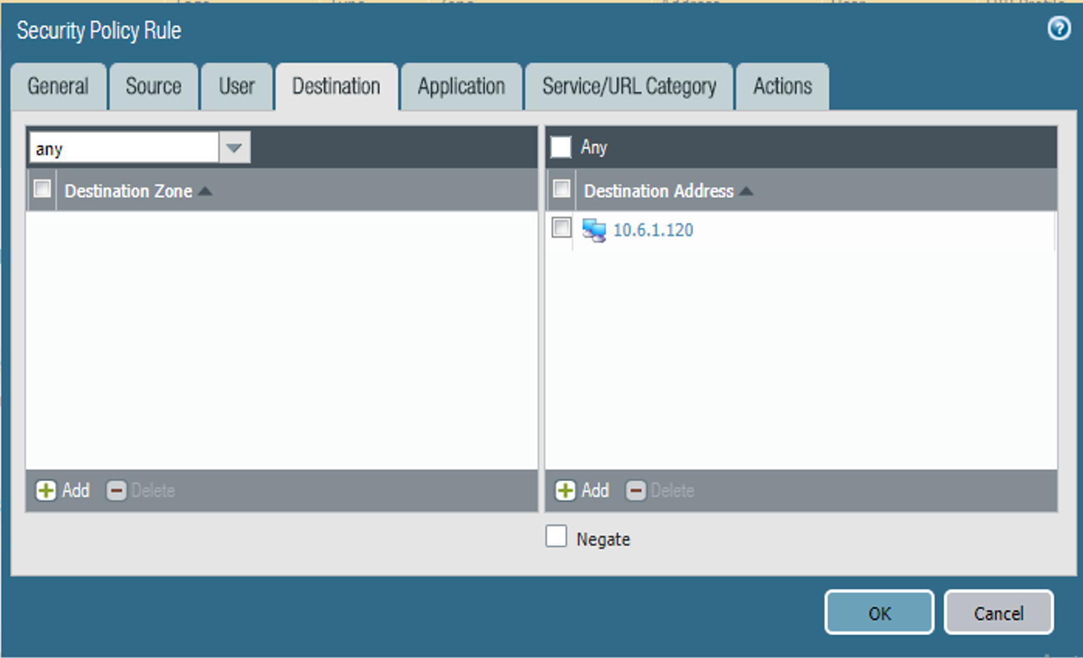
Select the Destination tab.
On the Destination tab:
If the security rule applies to a specific destination zone:
Under the Destination Zone list box, select Add; a new destination list item appears.
For the new Source Zone list item, select the destination zone for this rule.
If the rule applies to only specific destination IP addresses:
Under the Destination Address list box, select Add; a new list item appears.
For the new list item, select the destination address for this rule.
Figure 2‑50 DMZ Access to MobileIron Security Rule Destination Address Configuration
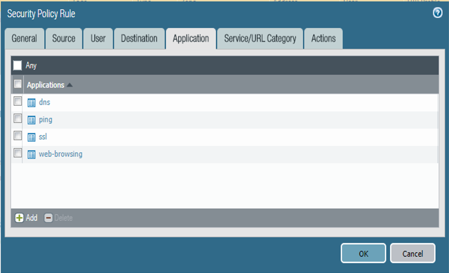
Select the Application tab.
On the Application tab:
Under the Applications list box, select Add; a new list item appears.
For the new Applications list item, select the application representing the protocol and port combination of the traffic to control.
Repeat Steps 9a and 9b for each application involving the same source and destination that would also have its traffic allowed or explicitly blocked (if otherwise allowed by a more permissive security rule).
Figure 2‑51 DMZ Access to MobileIron Security Rule Application Protocol Configuration
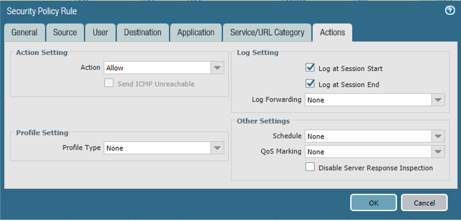
Select the Actions tab.
On the Actions tab: Unless explicitly blocking traffic permitted by a more permissive security rule, ensure that the Action Setting > Action drop-down menu is set to Allow.
Figure 2‑52 DMZ Access to MobileIron Security Rule Action Configuration
Click OK.
2.5.6.2.2 Implemented Security Policies
The implemented security policies are provided in Table 2‑1, Table 2‑2, and Table 2‑3. Configuration options that aren’t shown were left as their default values.
Table 2‑1 Implemented Security Policies
Name |
Tags |
Type |
Source Zone |
Source Address |
|---|---|---|---|---|
DMZAccessVirtualIPCore |
none |
universal |
Mobile_lab_WAN |
any |
CoretoAppleSrvs |
none |
universal |
Mobile_Lab_DMZ |
MI_Core |
AdminAccessToMI |
none |
interzone |
Mobile_Lab_GOVT |
MDS.govt.admin |
AppthorityConnectorAccessToMI-Core |
none |
interzone |
Mobile_Lab_GOVT |
govt.appthority |
MICoreObtainDeviceCERT |
none |
interzone |
Mobile_Lab_DMZ |
MI_Core |
MICoreAccessDNS |
none |
interzone |
Mobile_Lab_DMZ |
MI_Core |
MICoreRelaySMSNotifications |
none |
interzone |
Mobile_Lab_DMZ |
MI_Core |
MICoreSyncLDAP |
none |
interzone |
Mobile_Lab_DMZ |
MI_Core |
Table 2‑2 Implemented Security Policies
Name |
Source User |
Source Host Information Protocol Profile |
Destination Zone |
Destination Address |
|---|---|---|---|---|
DMZAccessVirtualIPCore |
any |
any |
any |
10.6.1.120 |
CoretoAppleSrvs |
any |
any |
any |
17.0.0.0/8 |
AdminAccessToMI |
any |
any |
Mobile_Lab_DMZ |
MI_Core;MI_Sentry |
AppthorityConnectorAccessToMI-Core |
any |
any |
Mobile_Lab_DMZ |
MI_Core |
MICoreObtainDeviceCERT |
any |
any |
Mobile_Lab_GOVT |
SCEP_server |
MICoreAccessDNS |
any |
any |
Mobile_Lab_GOVT |
DNS_Server |
MICoreRelaySMSNotifications |
any |
any |
Mobile_Lab_GOVT |
SMTP_Relay |
MICoreSyncLDAP |
any |
any |
Mobile_Lab_GOVT |
LDAP_Server |
Table 2‑3 Implemented Security Policies
Name |
Application |
Service |
Action |
Profile |
Options |
|---|---|---|---|---|---|
DMZAccessVirtualIPCore |
dns;ping;ssl;web-browsing |
any |
allow |
none |
none |
CoretoAppleSrvs |
any |
any |
allow |
none |
none |
AdminAccessToMI |
AdminAccessMI;ssh;ssl |
any |
allow |
none |
none |
AppthorityConnectorAccessToMI-Core |
AdminAccessMI;ssl;web-browsing |
any |
allow |
none |
none |
MICoreObtainDeviceCERT |
scep;web-browsing |
application-default |
allow |
none |
none |
MICoreAccessDNS |
dns |
application-default |
allow |
none |
none |
MICoreRelaySMSNotifications |
smtp |
application-default |
allow |
none |
none |
MICoreSyncLDAP |
ldap |
application-default |
allow |
none |
none |
2.5.7 Network Address Translation
To allow communication with external networks over the internet, the appliance also needs to be configured with Network Address Translation (NAT) rules. To configure NAT:
In the Palo Alto Networks Portal, navigate to Policies > NAT.
Below the details pane, select Add; the NAT Policy Rule form opens.
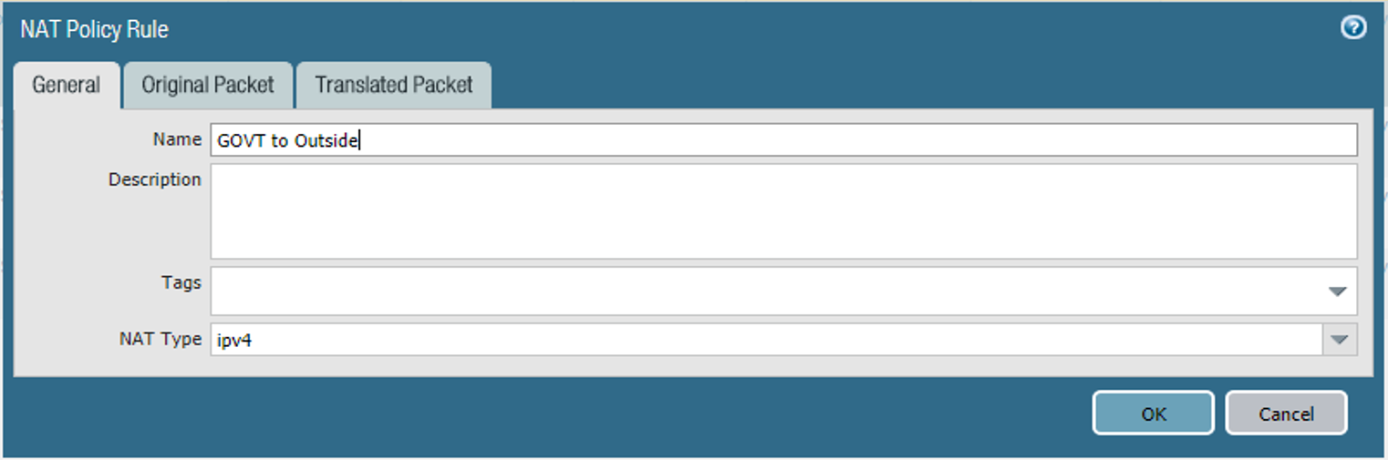
In the NAT Policy Rule form, on the General tab:
In the Name field, provide a unique name for this NAT policy rule.
Ensure the NAT Type drop-down menu is set to ipv4.
Figure 2‑53 Outbound NAT Rule
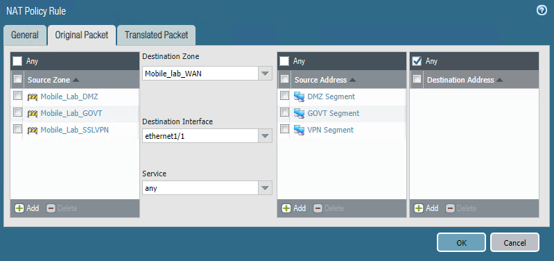
Select the Original Packet tab.
On the Original Packet tab:
Under the Source Zone list box, select Add; a new Source Zone list item appears.
For the new Source Zone list item, select the zone that represents your LAN subnet; in this sample implementation, that is Mobile_Lab_GOVT.
Repeat Steps 5a and 5b to add the zone that represents your DMZ; in this sample implementation, that is Mobile_Lab_DMZ.
Repeat Steps 5a and 5b to add the zone that represents your SSL VPN; in this sample implementation, that is Mobile_Lab_SSLVPN.
For the Destination Zone drop-down menu, select the zone that represents the internet; in this sample implementation, that is Mobile_lab_WAN.
For the Destination Interface, select the adapter that is physically connected to the same subnet as your internet gateway; in this sample implementation, that is ethernet1/1.
Under the Source Address list box, select Add; a new Source Address list item appears.
For the new Source Address list item, select the address that represents the subnet (IP address range) for the LAN.
Repeat Steps 5f and 5g to add the address representing the DMZ subnet.
Repeat Steps 5f and 5g to add the address representing the SSL VPN subnet.
Figure 2‑54 Outbound NAT Original Packet Configuration
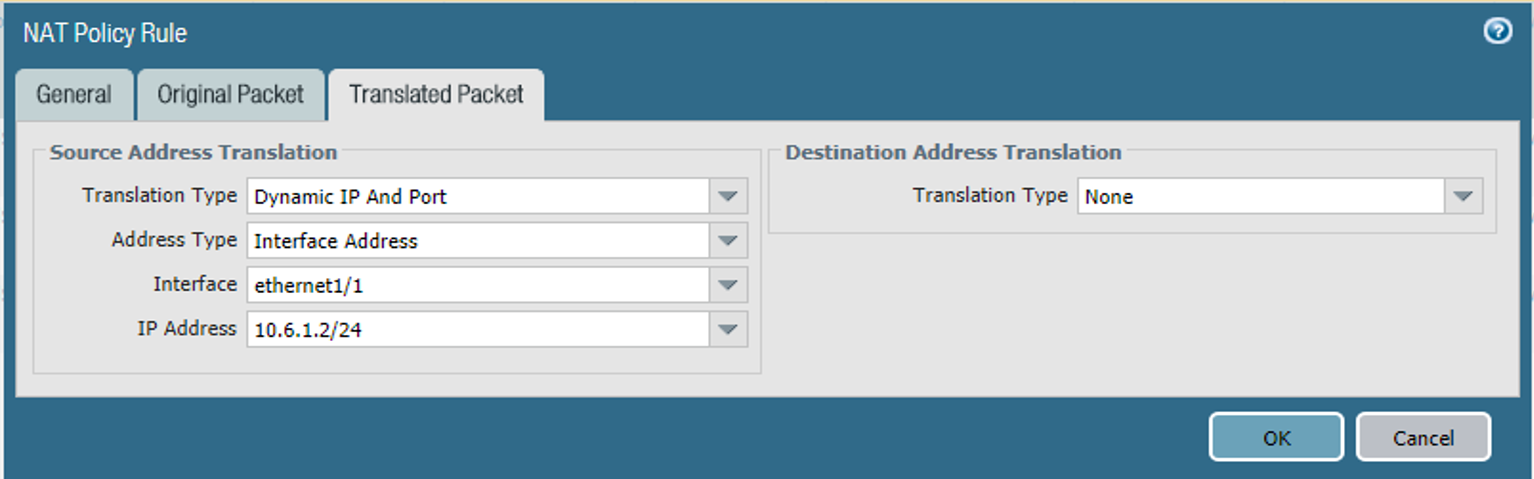
Select the Translated Packet tab.
On the Translated Packet tab, under Source Address Translation:
For the Translation Type drop-down menu, select Dynamic IP and Port.
For the Address Type drop-down menu, select Interface Address.
For the Interface drop-down menu, select the same interface selected in Step 5e.
For the IP Address drop-down menu, select the IPv4 address on the same subnet as your internet gateway.
Figure 2‑55 Outbound NAT Translated Packet Configuration
Select OK.
2.5.8 Configure SSL VPN
The SSL VPN enables remote mobile device users to create an encrypted connection to the enterprise from unencrypted networks (e.g., public Wi-Fi hot spots).
2.5.8.1 Configure End-User Authentication
The following steps establish the integrations and configurations related to mobile user identification and authentication.
2.5.8.1.1 Configured Server Profile
The following steps integrate this appliance with Microsoft Active Directory Domain Services to manage mobile user permissions via AD groups and roles.
In the Palo Alto Networks Portal, navigate to Devices > Server Profiles > LDAP.
Below the details pane, select Add; the LDAP Server Profile form opens.
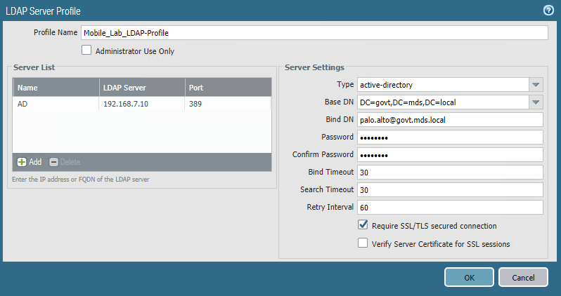
In the LDAP Server Profile form:
In the Profile Name field, enter a unique name to identify this profile.
Under the Service List box, select Add; a new Server List item appears.
In the new Service List item:
In the Name column, enter a name to identify the server.
In the LDAP Server column, enter the IP address of the LDAP server.
The value in the Port column defaults to 389; change this if your LDAP server communicates over a different port number.
Repeat Steps 3ci through 3ciii for each LDAP server that you intend to use.
Under Server Settings:
In the Type drop-down menu, select active-directory.
In the Base DN drop-down menu, select the DN for your Active Directory domain users who will use the SSL VPN.
In the Bind DN field, enter the Active Directory domain user account that will authenticate to LDAP to perform queries.
In the Password field, enter the password for the Active Directory user account specified in the previous step.
In the Confirm Password field, reenter the password entered in the previous step.
Click OK.
Figure 2‑56 LDAP Profile
2.5.8.2 Configure Authentication Profile
In the Palo Alto Networks Portal, navigate to Device > Authentication Profile.
Under the details pane, select Add; the Authentication Profile form opens.
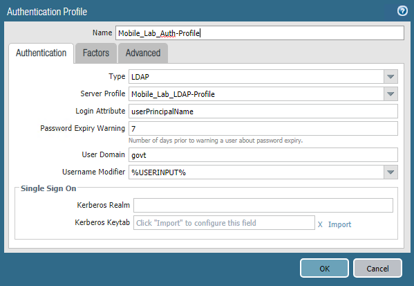
In the Authentication Profile form:
In the Name field, provide a unique name to identify this authentication profile.
On the Authentication tab:
For the Type drop-down menu, select LDAP.
For the Server Profile drop-down menu, select the name of the LDAP Server Profile created in the previous section.
For the Login Attribute field, enter userPrincipalName.
For the User Domain, enter the name of your enterprise domain; our sample implementation uses govt.
Figure 2‑57 Authentication Profile
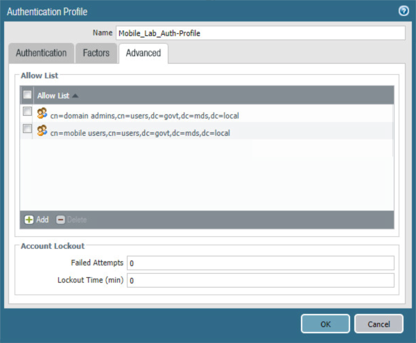
Select the Advanced tab.
On the Advanced tab:
Under the Allow List box, select Add; this creates a new list item.
In the new list item, select the Active Directory group for your mobile users.
Repeat Steps 3di and 3dii for any additional groups that should authenticate to the SSL VPN.
Click OK.
Figure 2‑58 Advanced Authentication Profile Settings
2.5.8.3 Configure User Identification
In the Palo Alto Networks Portal, navigate to Device & User Identification.
In the details pane, select the Group Mapping Settings tab.
Below the details pane, select Add. The Group Mapping form opens.
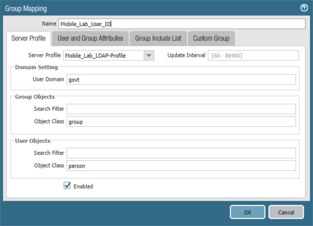
In the Group Mapping form:
In the Name field, enter a unique name to identify this group mapping.
In the Server Profile tab:
For the Server Profile drop-down menu, select the LDAP Server Profile created previously.
For Domain Setting > User Domain, enter the name of your Active Directory domain; this sample implementation uses govt.
Figure 2‑59 LDAP Group Mapping
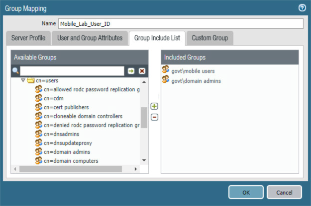
Select the Group Includes List tab.
On the Group Includes List tab:
In the Available Groups list box, expand the Active Directory domain to reveal configured user groups.
For each Active Directory group to be included in this User Identification configuration:
1. Select the Active Directory group.
2. Select the plus icon to transfer the group to the Included Groups list box.
Figure 2‑60 LDAP Group Include List
Select OK.
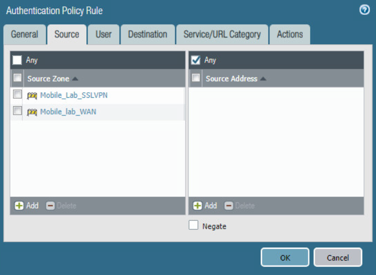
2.5.8.4 Configure Authentication Policy Rule
Navigate to Policies > Authentication.
Click Add.
Give the policy a name. In this implementation, Mobile_Lab_Auth_Rule was used.
Click Source.
Under Source Zone, click Add. Select the SSL VPN zone.
Under Source Zone, click Add. Select the WAN zone.
Figure 2‑61 Authentication Policy Source Zones
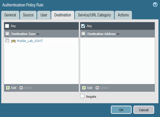
Click Destination.
Under Destination Zone, click Add.
Select the LAN zone (in this implementation, Mobile_Lab_GOVT).
Figure 2‑62 Authentication Policy Destination Zones
Click Service/URL Category.
Under service, click Add.
Select service-http.
Under service, click Add.
Select service-https.
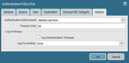
Click Actions.
Next to Authentication Enforcement, select default-web-form.
Leave Timeout and Log Settings as their default values.
Figure 2‑63 Authentication Profile Actions
Click OK and commit the changes.
2.5.9 Import Certificates
Certificates need to be imported into the appliance to configure certificate profiles that will affect how they are used in supporting communication with other systems. In particular, device certificates issued to mobile devices will be used to identify and authenticate mobile users.
Note: The certificate private keys must be password-protected to import them into the firewall.
In the Palo Alto Networks Portal, navigate to Device > Certificate Management > Certificates.
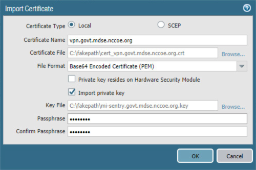
Under the details pane, select Import; the Import Certificate form opens.
In the Import Certificate form:
For the Certificate Type, select Local.
For the Certificate Name field, enter a unique name to identify this certificate.
Next to the Certificate File field, Select Browse… to specify the full path to the file containing the certificate.
For the File Format drop-down menu, select the certificate encoding appropriate to the certificate file; this example assumes the certificate and private key are in separate files, and select PEM. Note: The certificate’s private key must be password-protected to import it into Palo Alto Networks appliances.
If the certificate identifies the Palo Alto Networks appliance:
Enable the Import private key checkbox.
Next to Key File, select Browse… to specify the full path to the file containing the private key for the uploaded certificate.
For the Passphrase field, enter the pass phrase protecting the private key.
For the Confirm Passphrase field, re-enter the pass phrase protecting the private key.
Figure 2‑64 Import MobileIron Certificate
Select OK.
Repeat Step 3 for each certificate to import into the Palo Alto Networks appliance. This will include all certificates that the appliance will use to identify itself or authenticate to remote systems, all certificates in the chain of trust for each such certificate, and any chain-of-trust certificates supporting identity verification for remote systems to which this appliance will require certificate-based identification and authentication. This sample implementation uses certificates for the following systems:
server certificate for this appliance issued by DigiCert
DigiCert root CA certificate
DigiCert subordinate CA certificate
Microsoft CA enterprise root certificate
Microsoft CA enterprise subordinate CA certificate
2.5.10 Configure Certificate Profile
In the Palo Alto Networks Portal, navigate to Device > Certificate Management > Certificate Profile.
Under the details pane, select Add; the Certificate Profile form opens.
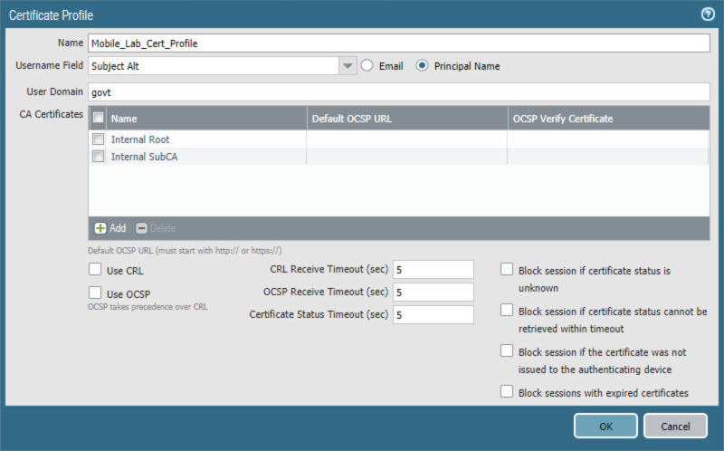
In the Certificate Profile form:
In the Name field, enter a unique name to identify this certificate profile.
In the Username Field drop-down menu, select Subject Alt.
Select the Principal Name option.
In the User Domain field, enter the Active Directory domain name for your enterprise; this sample implementation uses govt.
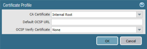
Under the CA Certificate list box, select Add; a secondary Certificate Profile form appears.
In the secondary Certificate Profile form, in the CA Certificate drop-down menu, select the Microsoft Active Directory Certificate Services root certificate uploaded in Section 2.5.9.
Click OK.
Repeat Step 3f for each intermediary certificate in the trust chain between the root certificate and the subordinate CA certificate that issues certificates to mobile devices.
Figure 2‑65 Certificate Profile
Click OK.
Figure 2‑66 Internal Root Certificate Profile
Click OK.
2.5.11 Configure SSL/TLS Service Profile
The following steps will configure the SSL/TLS profile, which determines what certificates to trust when mobile devices are connecting to the VPN and what certificate to use when establishing outbound SSL/TLS connections.
In the Palo Alto Networks Portal, navigate to Device > Certificate Management > SSL/TLS Service Profile.
Below the details pane, select Add; the SSL/TLS Service Profile form opens.
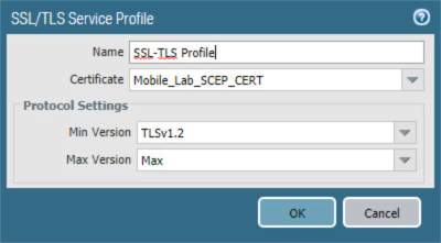
In the SSL/TLS Service Profile form:
In the Name field, enter a unique name to identify this service profile.
For the Certificate drop-down menu, select the certificate to use for this SSL/TLS service profile; our sample implementation uses a client certificate obtained from a Microsoft enterprise CA via SCEP.
For the Min Version drop-down menu, select TLSv1.2. For Max Version, select Max.
Select OK.
Figure 2‑67 SSL/TLS Service Profile
Repeat Step 3 to add an identical SSL/TLS service profile for this applianceʼs server certificate issued through DigiCert.
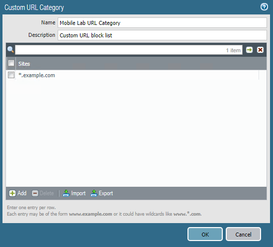
2.5.12 URL Filtering Configuration
Navigate to Objects > Custom Objects > URL Category.
Click Add.
Give the category a name and description.
Add sites to be blocked. For this example, *.example.com was used.
Figure 2‑68 Custom URL Category
Click OK.
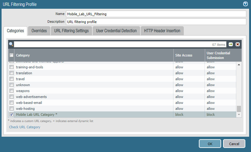
Navigate to Objects > Security Profiles > URL Filtering.
Check the box next to default and click Clone.
Select default from the window that appears.
Click OK.
Click the newly created profile, default-1.
Give the newly created profile called default-1 a meaningful name and provide a description for the new profile.
Scroll to the bottom of the list. The name of the created category will be last on the list.
Click the option below Site Access and next to your created URL category.
Set the Site Access option to block.
Figure 2‑69 URL Filtering Profile
Click OK.
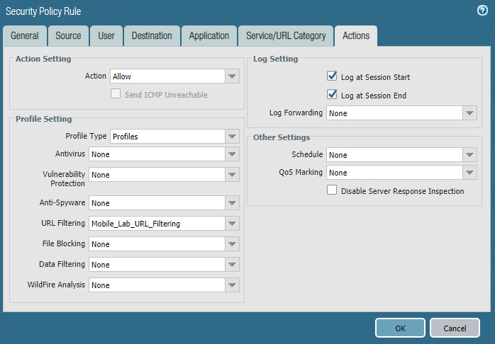
Navigate to Policies > Security.
Click the default outbound policy for the internal network (not VPN).
Click Actions.
Next to Profile Type, select Profiles.
Next to URL Filtering, select the newly created profile.
Click OK.
Repeat Steps 18 through 21 for the SSL VPN outbound traffic.
Figure 2‑70 URL Filtering Security Policy
Click Commit in the upper right-hand corner.
In the popup window, click Commit.
2.5.13 GlobalProtect Gateway and Portal Configuration
The SSL VPN configuration requires creation of both a GlobalProtect gateway and a GlobalProtect portal, the latter of which could be used to manage VPN connections across multiple gateways. In this sample implementation, only a single gateway and portal are configured.
2.5.13.1 Configure GlobalProtect Gateway
The GlobalProtect gateway provides remote users with secure access to internal resources based on their Microsoft AD group. To configure the GlobalProtect gateway:
In the Palo Alto Networks Portal, navigate to Network > GlobalProtect > Gateways.
Below the details pane, select Add; the GlobalProtect Gateway Configuration form opens.
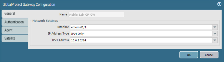
In the GlobalProtect Gateway Configuration form, on the General tab:
In the Name field, enter a unique name to identify this GlobalProtect Gateway.
Under Network Settings:
In the Interface drop-down menu, select the physical interface connected to the subnet on which the internet gateway device is located.
In the IPv4 Address drop-down menu, select the IP address associated with the physical interface specified in the previous step.
Figure 2‑71 General GlobalProtect Gateway Configuration
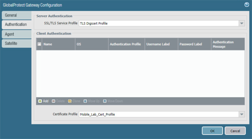
Select the Authentication tab.
In the Authentication tab:
For the Server Authentication > SSL/TLS Service Profile drop-down menu, select the TLS/SSL profile associated with the publicly trusted server certificate for this appliance.
For the Client Authentication > Certificate Profile drop-down menu, select the client TLS/SSL profile associated with the internally trusted client certificates issued to mobile devices.
Figure 2‑72 GlobalProtect Authentication Configuration
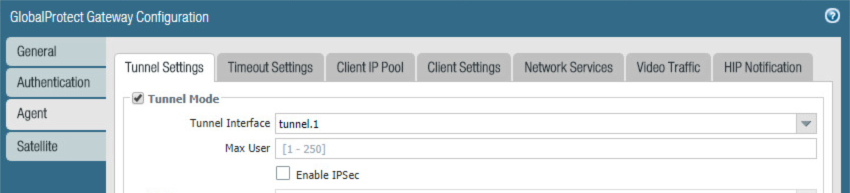
Select the Agent tab.
On the Agent > Tunnel Settings tab:
Select the Tunnel Mode checkbox.
Select the Enable IPSec checkbox to disable IPSec.
Figure 2‑73 GlobalProtect Tunnel Configuration
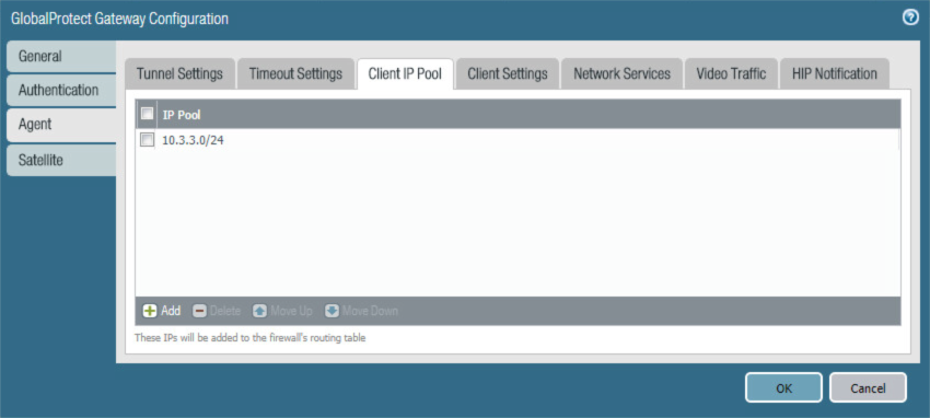
Select the Agent > Client IP Pool tab.
On the Agent > Client IP Pool tab:
Below the IP Pool list box, select Add; a new list item will appear.
For the new IP Pool list item, enter the network address for the IP address pool from which connected devices will be allocated an IP address.
Figure 2‑74 VPN Client IP Pool
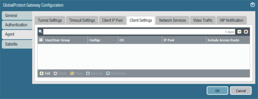
Select the Agent > Client Settings tab.
On the Agent > Client Settings tab:
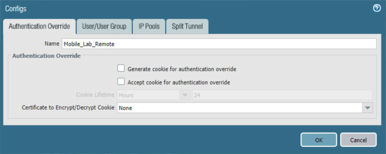
Under the Client Settings list box, select Add; the Configs form opens.
Figure 2‑75 VPN Client Settings
In the Configs form on the Authorization Override tab, enter a unique name to identify this client configuration.
Figure 2‑76 VPN Authentication Override Configuration
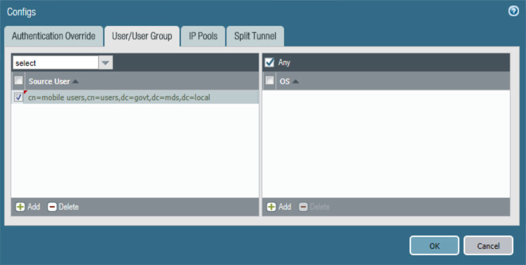
Select the User/User Group tab.
On the User/User Group tab:
1. Below the Source User list box, select Add; a new list item appears.
2. In the Source User list item, select the Microsoft AD user group to grant access to internal resources through this GlobalProtect gateway.
Figure 2‑77 VPN User Group Configuration
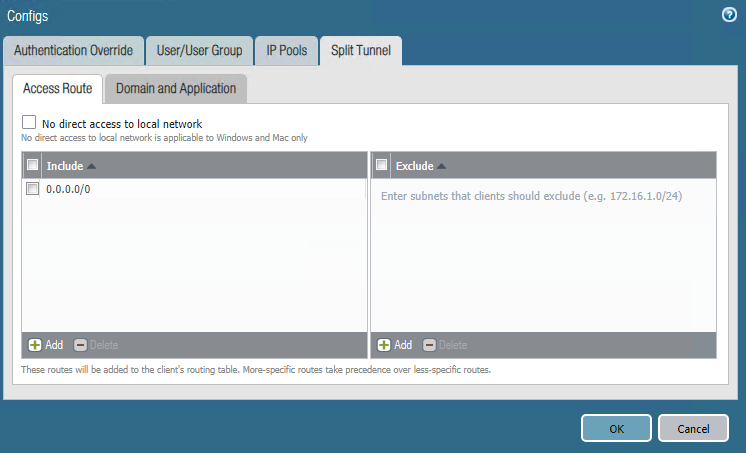
Select the Split Tunnel tab.
On the Split Tunnel tab, on the Access Route tab:
Under the Include list box, select Add; a new list item appears.
In the new Include list item, enter 0.0.0.0/0. This enforces full tunneling.
Figure 2‑78 VPN Split Tunnel Configuration
Click OK.
Click OK.
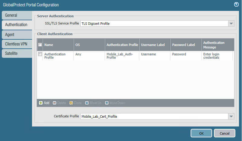
2.5.13.2 Configure GlobalProtect Portal
In the Palo Alto Networks Portal, navigate to Network > GlobalProtect > Portal.
Below the details pane, select Add; the GlobalProtect Portal Configuration form opens.
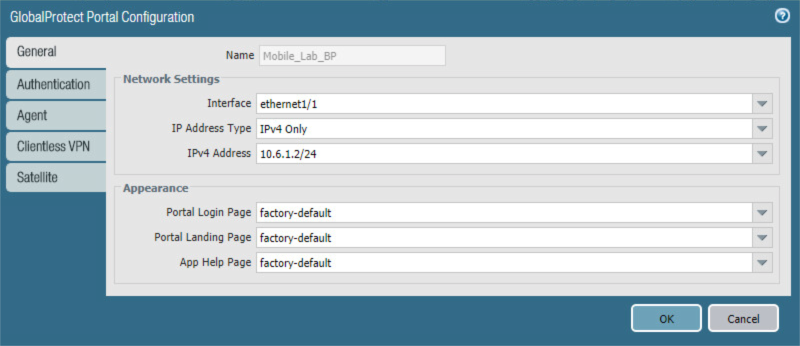
In the GlobalProtect Portal Configuration form, on the General tab:
In the Name field, enter a unique name to identify this GlobalProtect portal.
In the Interface drop-down menu, select the physical interface connected to the subnet where the internet gateway device is located.
In the IP Address Type drop-down menu, select IPv4 Only.
Figure 2‑79 GlobalProtect Portal Configuration
Select the Authentication tab.
In the Authentication tab:
For the Server Authentication > SSL/TLS Service Profile drop-down menu, select the SSL/TLS service profile based on your third-party server certificate.
For the Certificate Profile drop-down menu, select the client TLS/SSL profile associated with the internally trusted client certificates issued to mobile devices.
Click Add.
Enter a profile name. In this example implementation, Client Authentication was used.
For the Authentication Profile drop-down menu, select the previously created authentication profile.
Click OK.
Figure 2‑80 GlobalProtect Portal SSL/TLS Configuration
Select the Agent tab.
On the Agent tab:
Below the Agent list box, select Add; the Configs form will open.
In the Configs form:
In the Authentication tab, below Components that Require Dynamic Passwords, check the box next to Portal.
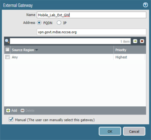
In the External tab, under the External Gateways list box select Add; the External Gateway form opens.
In the External Gateway form:
1. In the Name field, enter a unique name to identify this external gateway.
2. For the Address option, enter the FQDN for this appliance; in this sample implementation, the FQDN is vpn.govt.mdse.nccoe.org.
3. Below the Source Region list box, select Add; a new list item appears.
4. In the new Source Region list item, select Any.
5. Select the Manual checkbox.
6. Click OK.
Figure 2‑81 GlobalProtect External Gateway Configuration
Below the Trusted Root CA list box, select Add; a new list item appears.
In the new Trusted Root CA list item, select your internal CA root certificate.
Repeat Steps 7biii and 7biv to add each certificate in your internal or third-party certificate trust chains used when mobile devices contact the GlobalProtect portal.
Click App. Ensure that Connect Method is set to User-logon (Always On).
Figure 2‑82 GlobalProtect Portal Agent Configuration
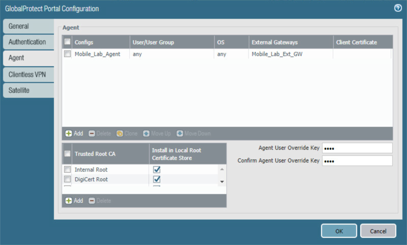
Click OK.
2.5.14 Configure Automatic Threat and Application Updates
In the PAN-OS portal, navigate to Device > Dynamic Updates.
Click Check Now at the bottom of the page.
Under Applications and Threats, click Download next to the last item in the list, with the latest Release Date. It will take a minute to download the updates.
When the download completes, click Done.
Click Install next to the downloaded update.
Click Continue Installation.
When installation completes, click Close.
Next to Schedule, click the link with the date and time.
Figure 2‑83 Schedule Link

Select the desired recurrence. For this implementation, Weekly was used.
Select the desired day and time. For this implementation, Saturday at 23:45 was used.
Next to Action, select download-and-install.
Figure 2‑84 Threat Update Schedule
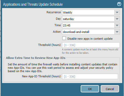
Click OK.
Click Commit in the upper right-hand corner.
In the popup window, click Commit.
2.6 Integration of Kryptowire EMM+S with MobileIron
Kryptowireʼs application vetting service uses the MobileIron application programming interface (API) to regularly pull current device application inventory information from MobileIron Core. Updated analysis results are displayed in the Kryptowire portal.
2.6.1 Add MobileIron API Account for Kryptowire
The following steps will create an administrative account that will grant Kryptowire the specific permissions it requires within MobileIron.
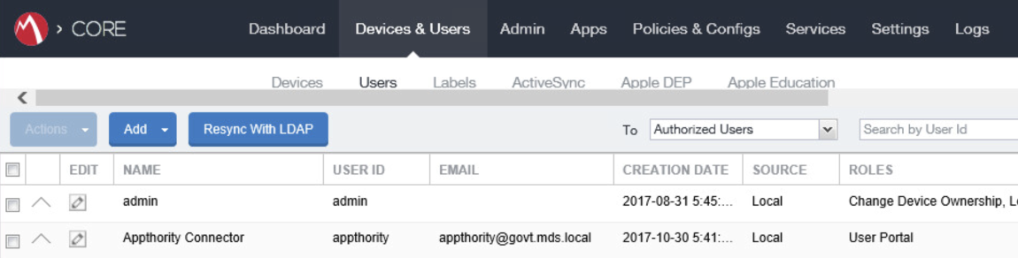
In the MobileIron Admin Portal, navigate to Devices & Users > Users.
On the Users page:
Select Add > Add Local User; the Add New User dialogue opens.
Figure 2‑85 MobileIron Users
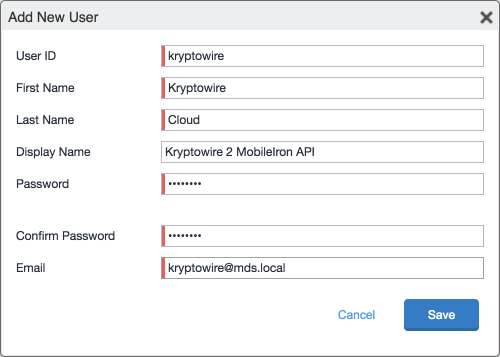
In the Add New User dialogue:
In the User ID field, enter the user identity that the Kryptowire cloud will authenticate under; our implementation uses a value of kryptowire.
In the First Name field, enter a generic first name for Kryptowire.
In the Last Name field, enter a generic last name for Kryptowire.
In the Display Name field, optionally enter a displayed name for this user account.
In the Password field, provide the password that the Kryptowire identity will use to authenticate to MobileIron.
In the Confirm Password field, enter the same password as in the preceding step.
In the Email field, provide an email account for the Kryptowire identity; this could be used in configuring automatic notifications and should be an account under the control of your organization.
Click Save.
Figure 2‑86 Kryptowire API User Configuration
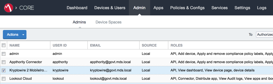
In the MobileIron Admin Portal, navigate to Admin > Admins.
On the Admins page:
Enable the account you created for Kryptowire during Step 2.
Select Actions > Assign to Space; this opens the Assign to Space dialogue for the Kryptowire account.
Figure 2‑87 MobileIron User List
In the Assign to Space dialogue:
In the Select Space drop-down menu, select Global.
Figure 2‑88 Kryptowire API User Space Assignment
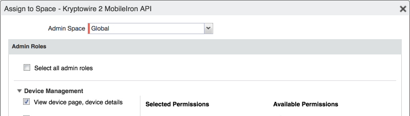
Enable each of the following settings:
Admin Roles > Device Management > View device page, device details
Admin Roles > Device Management > View dashboard
Admin Roles > Privacy Control > View apps and ibooks in device details
Admin Roles > Privacy Control > View device IP and MAC address
Admin Roles > App Management > View app
Admin Roles > App Management > View app inventory
Other Roles > Common Services Provider (CSP)
Other Roles > API
Click Save.
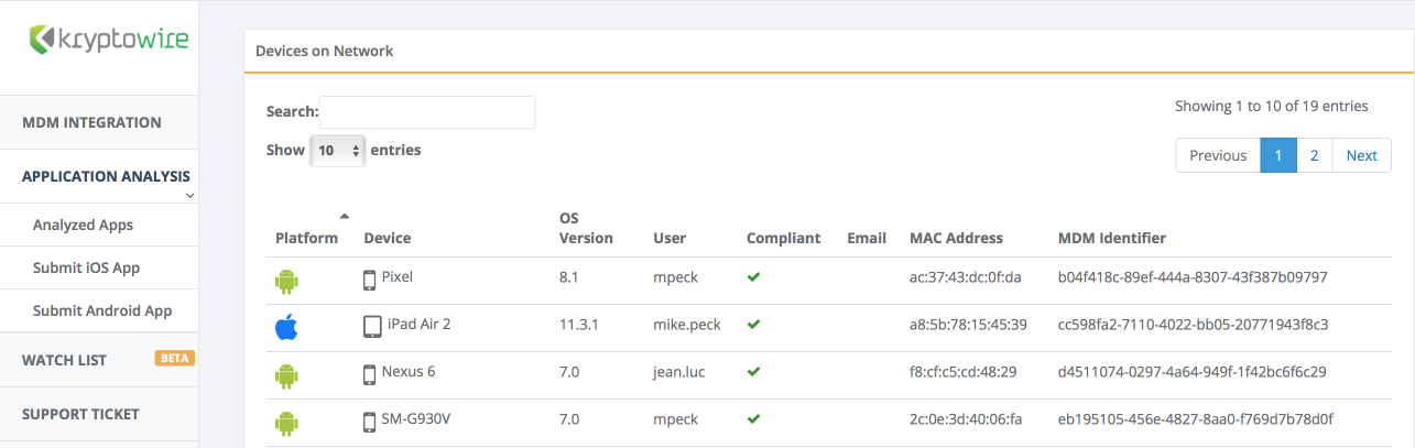
2.6.2 Contact Kryptowire to Create Inbound Connection
Once the MobileIron API account has been created, contact Kryptowire customer support to integrate your instance of MobileIron Core. Note that this will require creation of firewall rules that permit inbound connections from IP addresses designated by Kryptowire to MobileIron Core on port 443. Once the connection has been established, the Kryptowire portal will populate with information on devices registered with MobileIron. The EMM (Enterprise Mobility Management) ID presented by Kryptowire will be the same as the Universally Unique ID assigned to a device by MobileIron Core.
Figure 2‑89 Kryptowire Device List
2.7 Integration of Lookout Mobile Endpoint Security with MobileIron
Lookoutʼs Mobile Endpoint Security cloud service uses the MobileIron API to pull mobile device details and app inventory from MobileIron Core. Following analysis, Lookout uses the API to apply specific labels to devices to categorize them by the severity of any issues detected. MobileIron can be configured to automatically respond to the application of specific labels per built-in compliance actions.
2.7.1 Add MobileIron API Account for Lookout
The following steps will create an administrative account that will grant Lookout the specific permissions it requires within MobileIron.
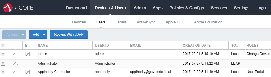
In the MobileIron Admin Portal, navigate to Devices & Users > Users.
On the Users page:
Select Add > Add Local User; the Add New User dialogue opens.
Figure 2‑90 MobileIron User List
In the Add New User dialogue:
In the User ID field, enter the user identity that the Lookout cloud will authenticate under. Our implementation uses a value of lookout.
In the First Name field, enter a generic first name for Lookout.
In the Last Name field, enter a generic last name for Lookout.
In the Display Name field, optionally enter a displayed name for this user account.
In the Password field, provide the password that the Lookout identity will use to authenticate to MobileIron.
In the Confirm Password field, enter the same password as in the preceding step.
In the Email field, provide an email account for the Lookout identity; since this may be used for alerts, it should be an account under the control of your organization.
Click Save.
Figure 2‑91 MobileIron Lookout User Configuration
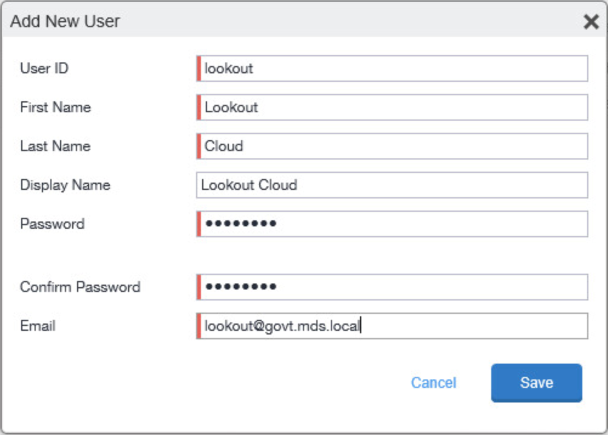
In the MobileIron Admin Portal, navigate to Admin.
On the Admin page:
Enable the account you created for Lookout during Step 2.
Select Actions > Assign to Space; this opens the Assign to Space dialogue for the Lookout account.
Figure 2‑92 Lookout MobileIron Admin Account
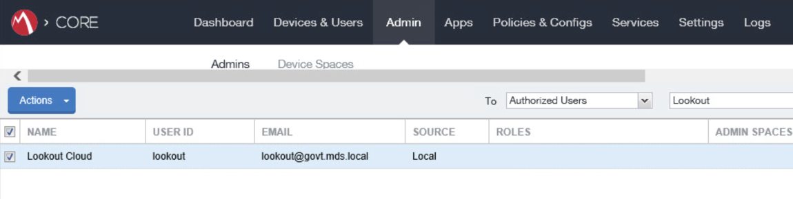
In the Assign to Space dialogue:
In the Select Space drop-down menu, select Global.
Figure 2‑93 Lookout Account Space Assignment
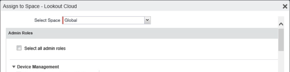
Enable each of the following settings:
Admin Roles > Device Management > View device page, device details
Admin Roles > Device Management > View dashboard
Admin Roles > Label Management > View Label
Admin Roles > Label Management > Manage Label
Admin Roles > Privacy Control > View apps and ibooks in device details
Admin Roles > Privacy Control > View device IP and MAC address
Admin Roles > App Management > Distribute app
Admin Roles > Logs and Event Management > View Audit logs
Admin Roles > Logs and Event Management > View events
Other Roles > CSP
Other Roles > Connector
Other Roles > API
Click Save.
2.7.2 Add MobileIron Labels for Lookout
Lookout will dynamically apply MobileIron labels to protected devices to communicate information about their current state. The following steps will create a group of Lookout-specific labels.
In the MobileIron Admin Portal, navigate to Devices & Users > Labels.
On the Labels page:
Select Add Label; the Add Label dialogue appears.
Figure 2‑94 MobileIron Label List
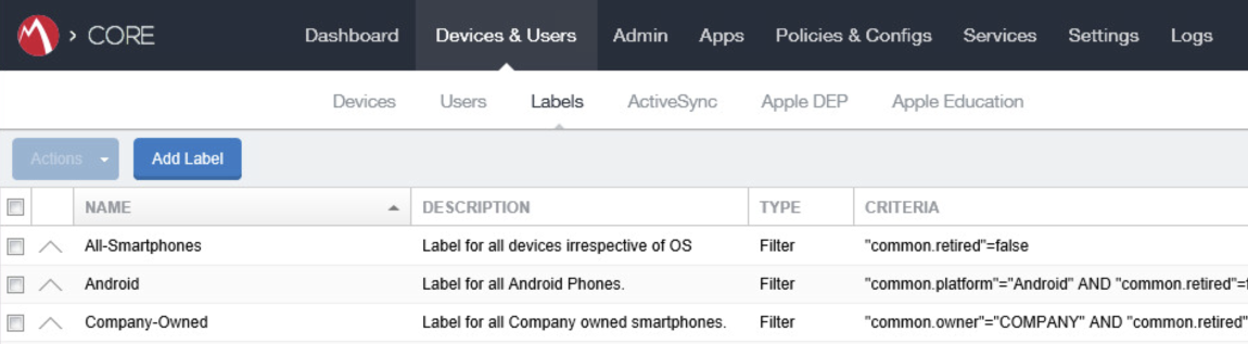
In the Add Label dialogue:
In the Name field, enter the name of the label. Note: future steps will use the Label Names presented here but use of these names is optional.
In the Description field, enter a brief description for this label.
For the Type option, select Manual; this hides all other form inputs.
Click Save.
Figure 2‑95 MTP Low Risk Label Configuration
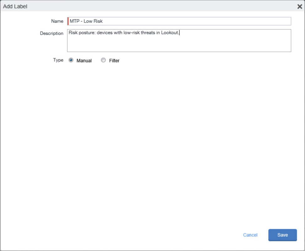
Complete Step 2 for each label in the following table:
Label Name
Purpose
Lookout for Work
Device enrollment
MTP - Pending
Lifecycle management: devices with Lookout not yet activated
MTP - Secured
Lifecycle management: devices with Lookout activated
MTP - Threats Present
Lifecycle management: devices with threats detected by Lookout
MTP - Deactivated
Lifecycle management: devices with Lookout deactivated
MTP - Low Risk
Risk posture: devices with a low risk score in Lookout
MTP - Moderate Risk
Risk posture: devices with a moderate risk score in Lookout
MTP - High Risk
Risk posture: devices with a high risk score in Lookout
Note: Administrators can choose to alter the label names to something more appropriate for their environment.
2.7.3 Add Lookout for Work for Android to MobileIron App Catalog
The following steps will add the Lookout for Work app for Android to MobileIron.
In the MobileIron Admin Portal, navigate to Apps > App Catalog.
On the App Catalog page, select Add; this starts the workflow to add a new app to the app catalog.
Figure 2‑96 MobileIron App Catalog
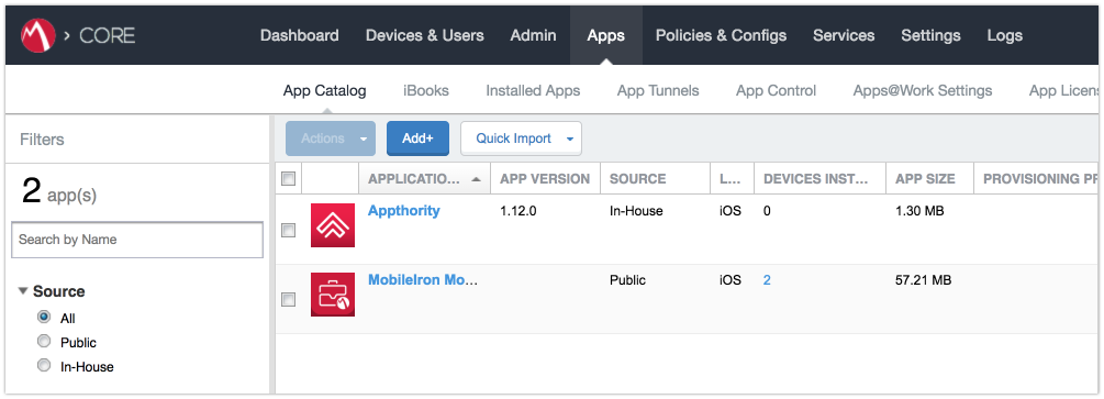
On the App Catalog > Choose page:
Select Google Play; additional controls will be displayed.
In the Application Name field, enter Lookout for Work.
Select Search; search results will be displayed in the lower pane.
In the list of search results, select the Lookout for Work app.
Select Next.
Figure 2‑97 Adding Lookout for Work to the MobileIron App Catalog
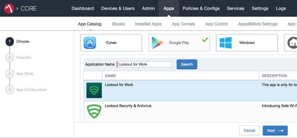
On the App Catalog > Describe page:
In Category drop-down menu, optionally assign the app to a category as appropriate to your MobileIron deployment strategy.
Select Next.
Figure 2‑98 Lookout for Work Application Configuration
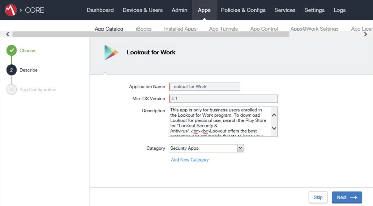
On the App Catalog > App Configuration page:
In the Apps@Work Catalog section, Enable Feature this App in the Apps@Work catalog.
Figure 2‑99 Lookout for Work Application Configuration
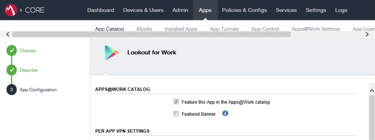
In the Android Enterprise (Android for Work [AFW]) section:
Enable Install this app for Android enterprise; additional controls display.
Enable Auto Update this App.
Ensure Silently Install is enabled.
Click Finish.
Figure 2‑100 Lookout for Work AFW Configuration
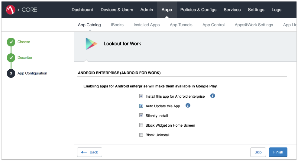
The Lookout for Work app should now appear in the App Catalog with the AFW indicator.
2.7.4 Apply Labels to Lookout for Work for Android
On the App Catalog page:
Enable Lookout for Work.
Select Actions > Apply To Labels; the Apply To Labels dialogue appears.
Figure 2‑101 Apply Lookout for Work to Android Devices
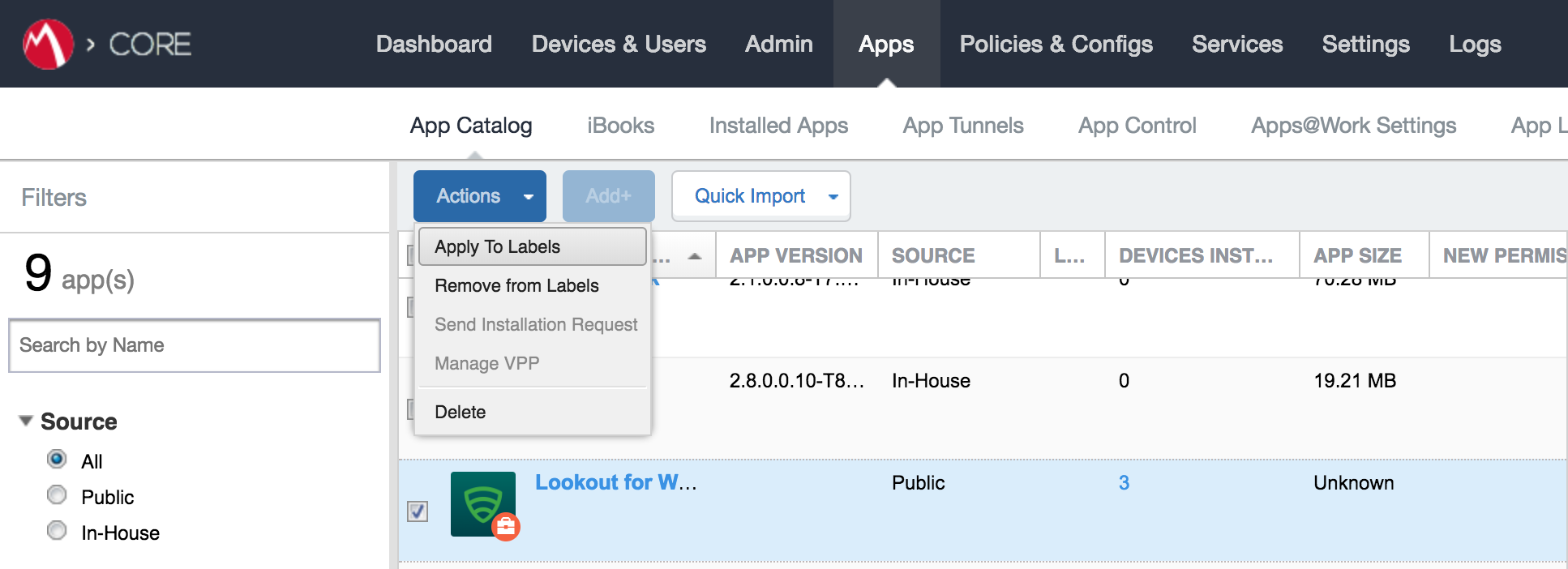
In the Apply To Labels dialogue:
Enable the Lookout for Work and Android labels, plus any other labels appropriate to your organization’s mobile security policies.
Select Apply.
Figure 2‑102 Apply To Labels Dialogue
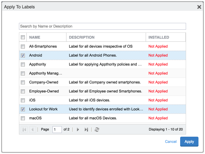
The Lookout for Work app appears with the Lookout for Work and Android labels applied.
Figure 2‑103 Lookout for Work with Applied Labels
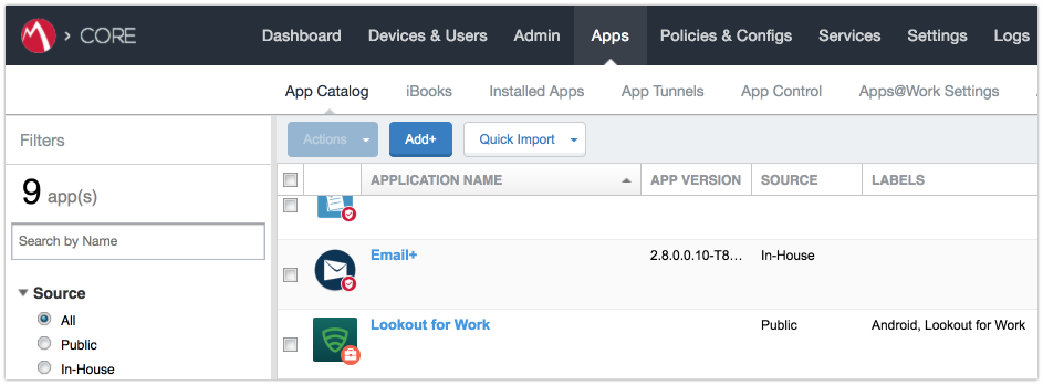
2.7.5 Add Lookout for Work app for iOS to MobileIron App Catalog
The following steps will add the Lookout for Work app for iOS to MobileIron, apply appropriate MobileIron labels, and create and upload a configuration file for one-touch activation of the app.
2.7.5.1 Import Lookout for Work App
In the MobileIron Admin Portal, navigate to Apps > App Catalog.
On the App Catalog page, select Add; this starts the workflow to add a new app to the app catalog.
Figure 2‑104 MobileIron App Catalog
On the App Catalog > Choose page:
Select iTunes; additional controls display.
In the Application Name field, enter Lookout for Work.
Select Search; the search results display in the lower pane.
In the list of search results, select the Lookout for Work app.
Select Next.
Figure 2‑105 Lookout for Work Selected From iTunes
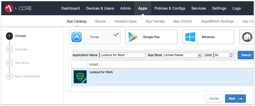
On the App Catalog > Describe page:
In Category drop-down menu, optionally assign the app to a category as appropriate to your MobileIron deployment strategy.
Select Next.
Figure 2‑106 Lookout for Work App Configuration
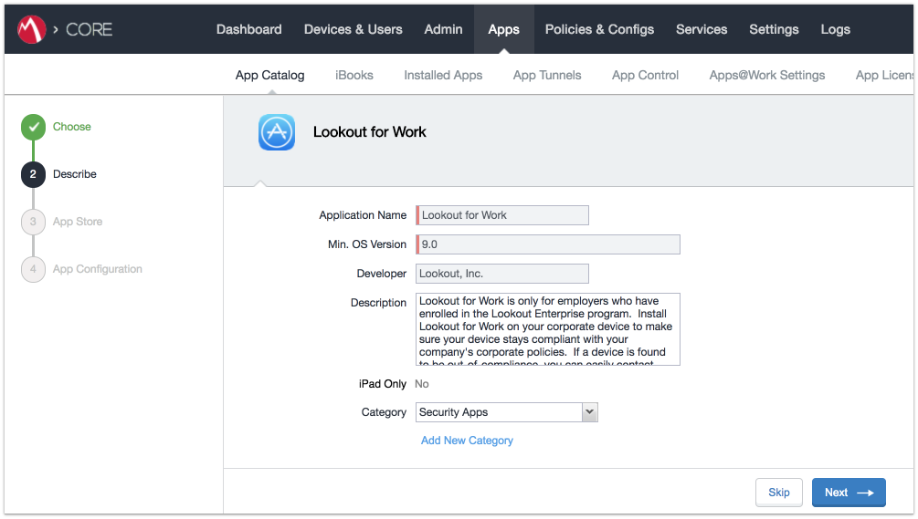
On the App Catalog > App Store page:
In the Apps@Work Catalog section:
Enable Allow conversion of app from unmanaged to managed (iOS 9 or later).
Enable Feature this App in the Apps@Work catalog.
Select Next.
Figure 2‑107 Lookout for Work App Configuration
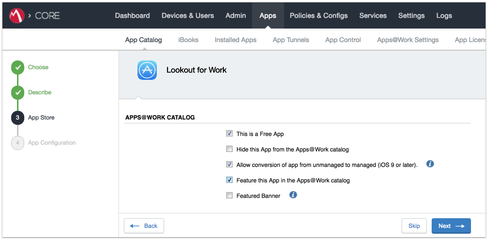
In the App Catalog > App Configuration section:
Enable Send installation request or send convert unmanaged to managed app request (iOS 9 and later) on device registration or sign-in.
Enable Advanced Settings > Automatically update app when new version is available.
Click Finish.
Figure 2‑108 Lookout for Work Managed App Settings
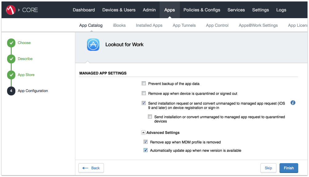
The Lookout for Work app should now appear in the App Catalog with AFW indicator.
Figure 2‑109 App Catalog with Lookout for Work
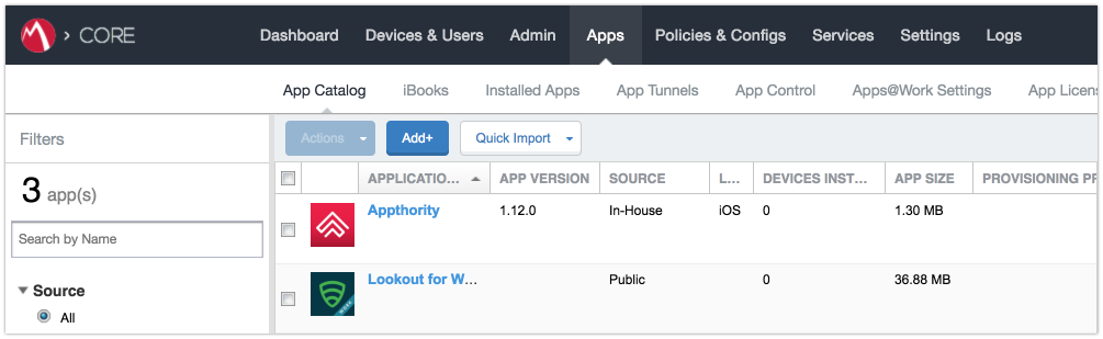
2.7.5.2 Apply MobileIron Labels to Lookout for Work App
On the App Catalog page:
Enable Lookout for Work.
Select Actions > Apply To Labels; the Apply To Labels dialogue will appear.
Figure 2‑110 Lookout for Work Selected
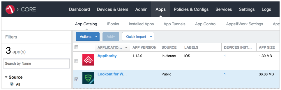
In the Apply To Labels dialogue:
Enable the Lookout for Work and iOS labels, plus any other labels appropriate to your organization’s mobile security policies.
Select Apply.
Figure 2‑111 Apply To Labels Dialogue
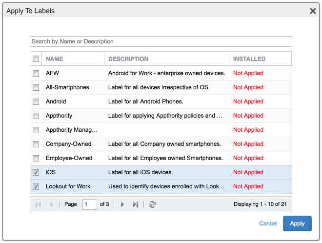
The Lookout for Work app appears with the Lookout for Work and iOS labels applied.
Figure 2‑112 App Catalog with Lookout for Work
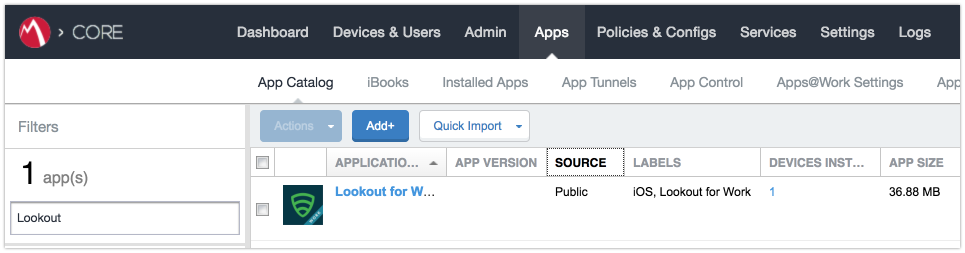
2.7.5.3 Create Managed App Configuration File for Lookout for Work
MobileIron can push a configuration file down to managed iOS devices to allow users to activate Lookout for Work. The following steps will create and upload the necessary file.
Using a plain text editor, create the following text file by replacing the asterisks on line 13 with your organization’s Global Enrollment Code.
<?xml version="1.0" encoding="UTF-8"?>

<!DOCTYPE plist PUBLIC "-//Apple//DTD PLIST 1.0//EN"

"https://www.apple.com/DTDs/PropertyList-1.0.dtd">

<plist version="1.0">

<dict>

<key>MDM</key>

<string>MOBILEIRON</string>

<key>DEVICE_UDID</key>

<string>$DEVICE_UDID$</string>

<key>EMAIL</key>

<string>$EMAIL$</string>

<key>GLOBAL_ENROLLMENT_CODE</key>

<string>*******</string>

</dict>

</plist>
In the MobileIron Admin Portal, navigate to Policies & Configs > Configurations.
On the Configurations Page:
Select Add New > iOS and OS X > iOS Only > Managed App Config; the New Managed App Config Setting dialogue opens.
Figure 2‑113 Importing Managed Application Configuration
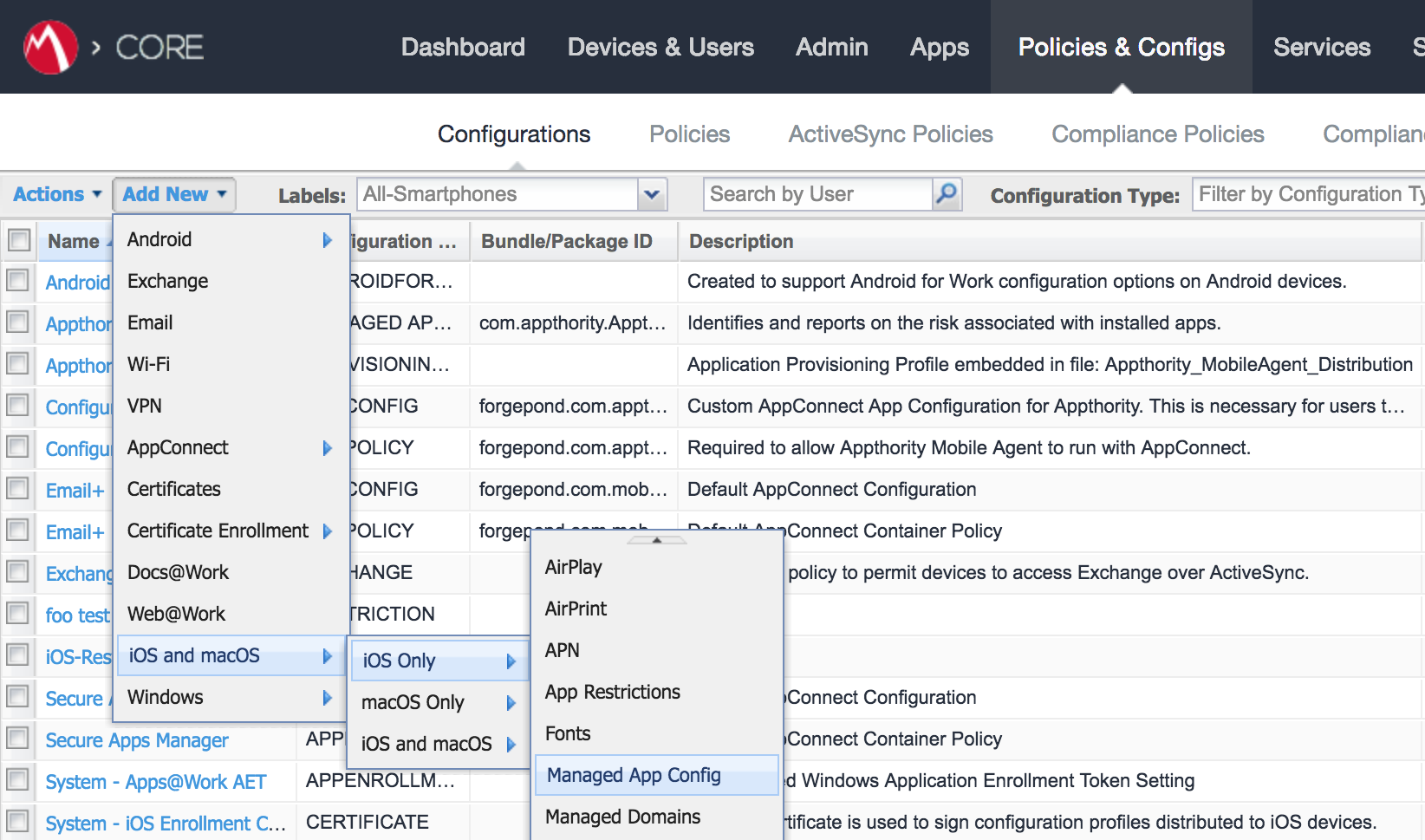
In the Managed App Config Setting dialogue:
In the Name field, provide a name for this configuration; our implementation used Activate Lookout.
In the Description field, provide the purpose for this configuration.
In the BundleId field, enter the bundle ID for Lookout at Work, which for our version was com.lookout.work.
Select Choose File… to upload the plist file created during Step 1.
Click Save.
Figure 2‑114 plist File Configuration
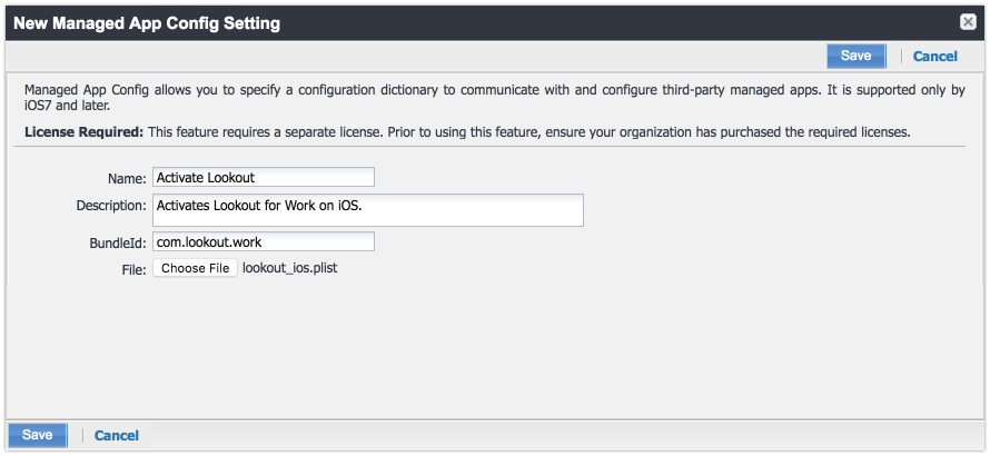
2.7.5.4 Apply Labels to Managed App Configuration for Lookout for Work
The following steps will apply the managed app configuration created in the previous section to labels.
In the MobileIron Admin Portal, navigate to Policies & Configs > Configurations.
On the Configurations page:
Enable the Lookout Activation managed app configuration created in the previous section.
Select Actions > Apply To Label; the Apply To Label dialogue opens.
Figure 2‑115 Lookout Configuration Selected
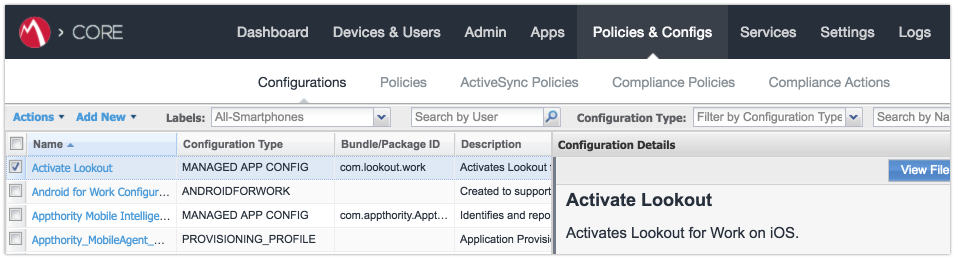
In the Apply To Label dialogue:
Enable the iOS and Lookout for Work labels.
Select Apply.
Figure 2‑116 Apply To Label Dialogue
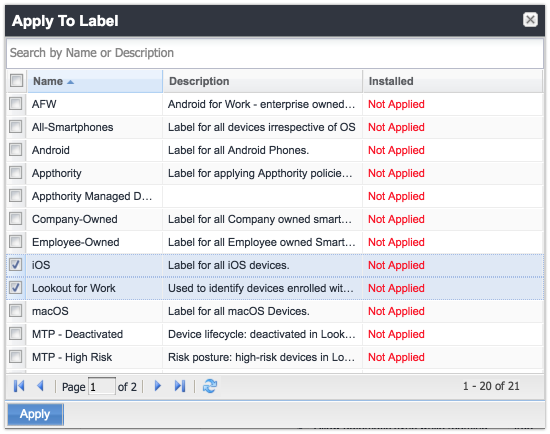
The system should now reflect that the Lookout for iOS and iOS labels have been applied to the Activate Lookout configuration.
Figure 2‑117 Lookout Configuration With Labels
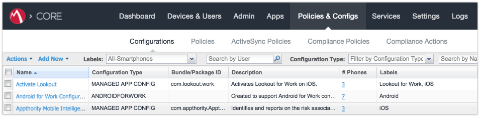
2.7.6 Add MDM Connector for MobileIron to Lookout MES
The following instructions will connect Lookout with your MobileIron instance and associate Lookout device states with the MobileIron labels created previously.
Using the most-recent version of MDM Service IP allowed addresses available from the Lookout support portal, configure your organization’s firewalls to permit inbound connections from the IP addresses provided on port 443 to your instance of MobileIron Core.
In the Lookout MES portal, navigate to Lookout > System > Connectors.
On the Connectors page:
Select Add Connector > MobileIron; a new form opens.
Figure 2‑118 Add Lookout Connector Display
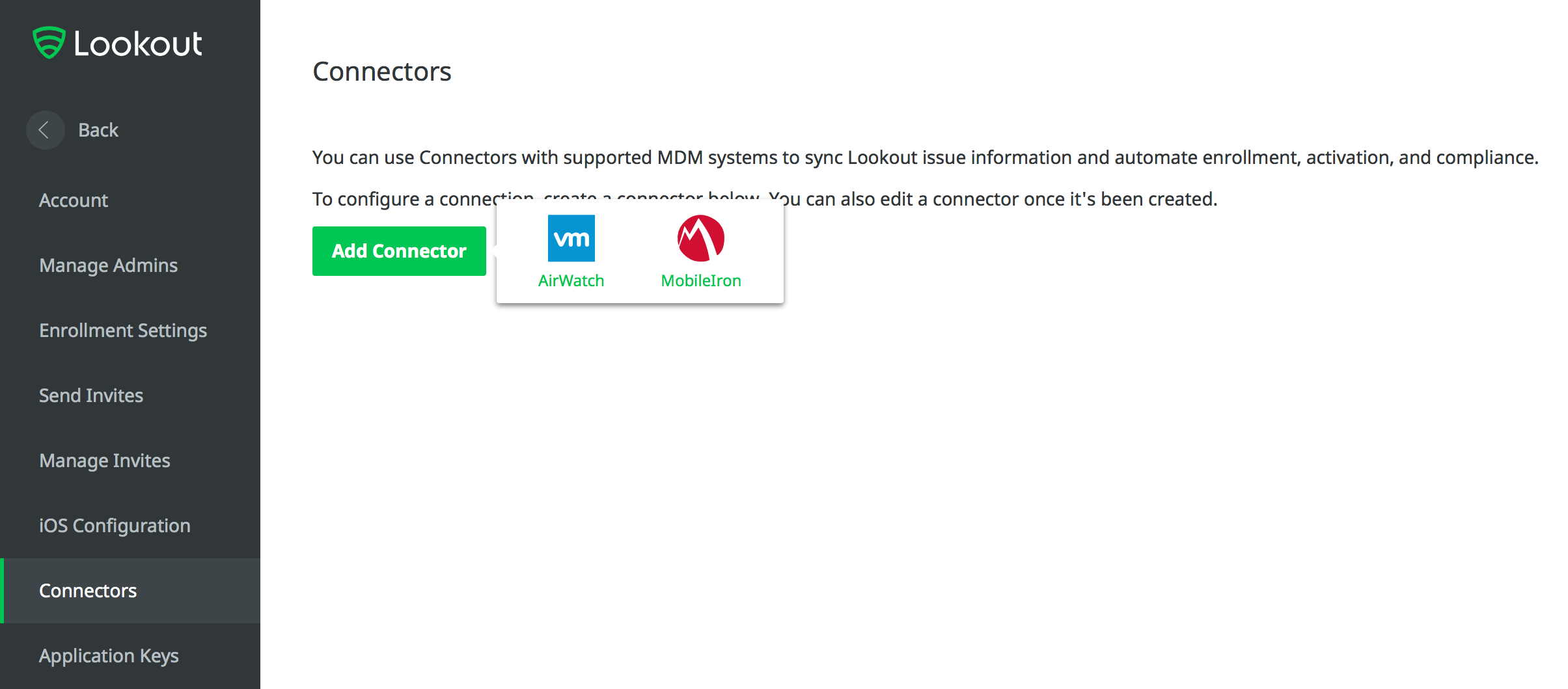
In the Connector Settings section of the form:
For the MobileIron URL field, enter the FQDN for your instance of MobileIron. In our example implementation, the URL was mi-core.govt.mdse.nccoe.org.
For the Username field, enter the User ID of the MobileIron admin account created in 2.7.1. In our example implementation, the User ID is lookout.
For the Password field, enter the password associated with that MobileIron admin account.
Select Create Connector; this enables additional sections of the form.
Figure 2‑119 Connector Settings
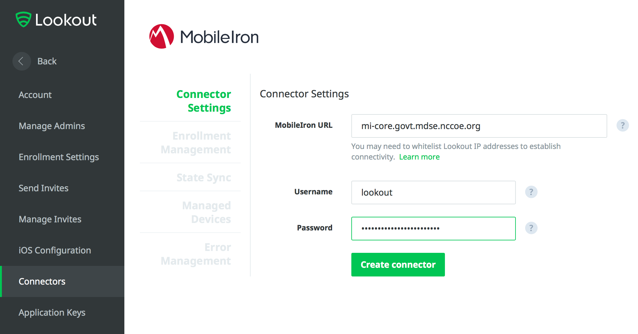
In the Enrollment Management section of the form:
Toggle Device Enrollment > Automatically drive Lookout for Work enrollment on MobileIron managed devices to On.
For the Device Enrollment > Use the following label to identify devices that should have the Lookout for Work app activated drop-down menu, select the Lookout for Work label.
Toggle Device Enrollment > Automatically send activation emails to MobileIron managed devices to On.
Select Save Changes.
Figure 2‑120 Connector Enrollment Settings
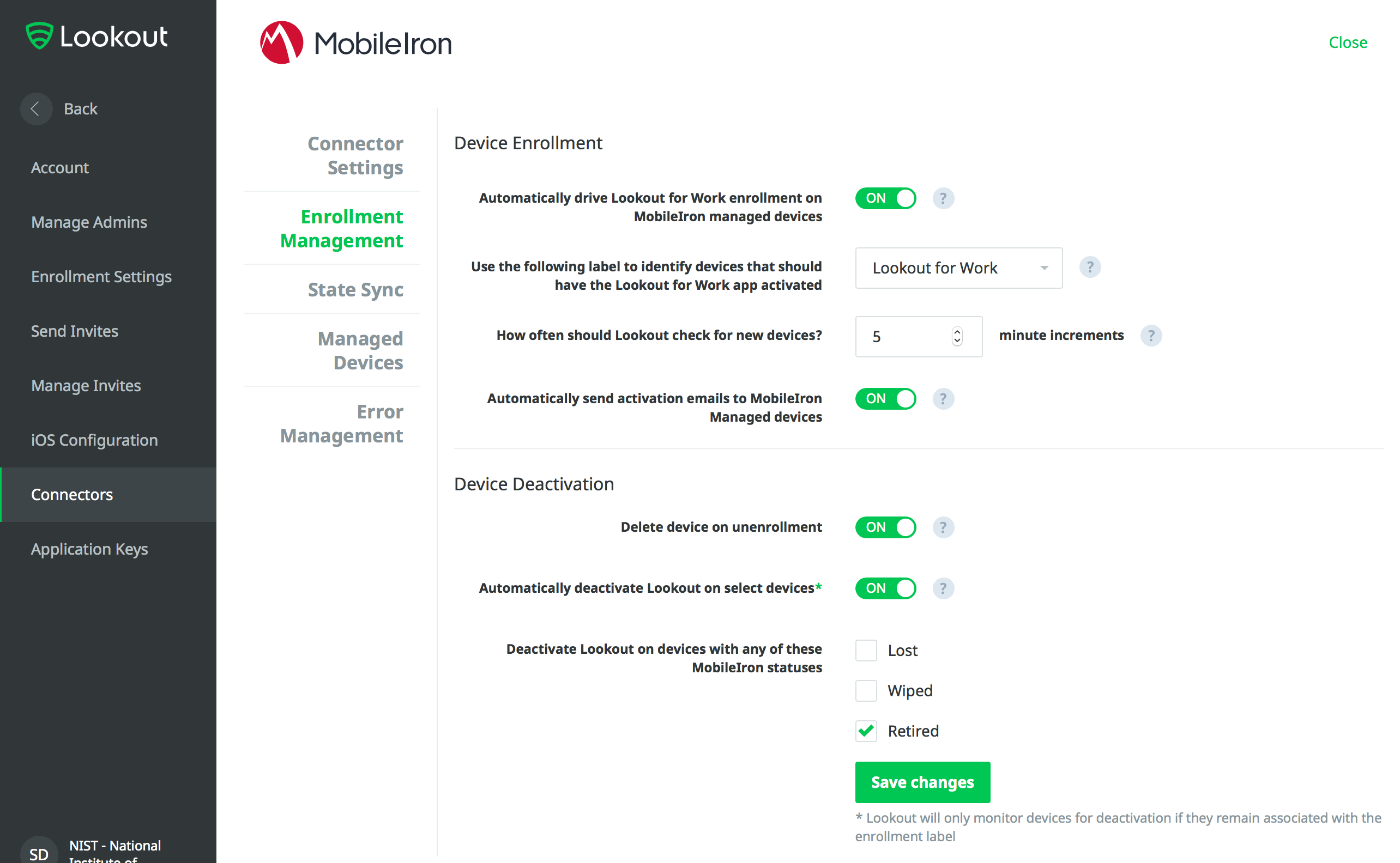
In the State Sync section of the form:
Toggle State Sync > Synchronize Device Status to MobileIron to On.
For each entry in the table below:
1. Toggle the control to On.
2. From the drop-down menu, select the MobileIron Label with the associated Purpose from the table in Section 2.6.2 Add MobileIron Labels for Lookout. We provide the Label Name we used for each Purpose in our example implementation.
State
Purpose
Label Name
Devices that have not activated Lookout yet
Lifecycle management: devices with Lookout not yet activated
MTP - Pending
Devices with Lookout activated
Lifecycle management: devices with Lookout activated
MTP - Secured
Devices on which Lookout is deactivated
Lifecycle management: devices with Lookout deactivated
MTP - Deactivated
Devices with any issues present
Lifecycle management: devices with threats detected by Lookout
MTP - Threats Detected
Devices with Low Risk issues present
Risk posture: devices with a low risk score in Lookout
MTP - Low Risk
Devices with Medium Risk issues present
Risk posture: devices with a moderate risk score in Lookout
MTP - Moderate Risk
Devices with High Risk issues present
Risk posture: devices with a high risk score in Lookout
MTP - High Risk
Note: Administrators can choose to alter the label names to something more appropriate for their environment.
Select Save Changes.
Figure 2‑121 Connector Sync Settings
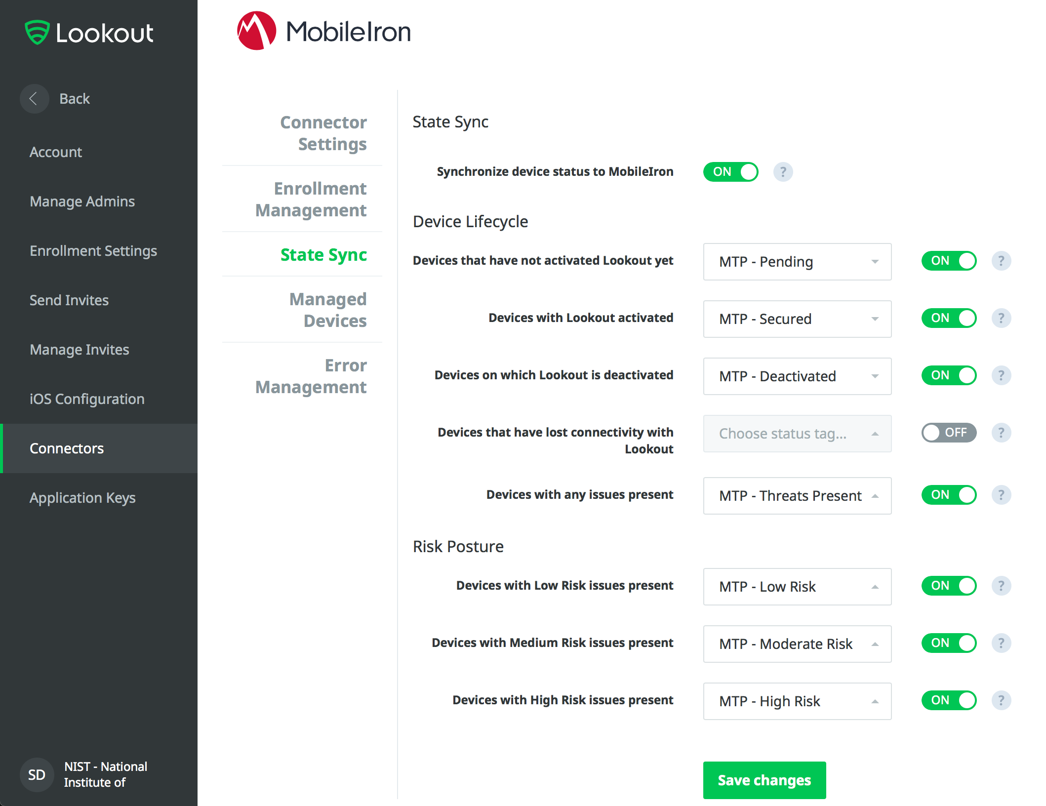
2.7.7 Configure MobileIron Risk Response
The following steps will allow MobileIron to generate responses to various device states as assigned to devices by Lookout (e.g., MTP - High Risk).
2.7.7.1 Add MobileIron App Control Rule
In the MobileIron Admin Portal, navigate to Apps > App Control.
Select Add; the Add App Control Rule dialogue appears.
In the Add App Control Rule dialogue:
In the Name field, enter Threats Present Trigger.
Of the Type options, select Required.
In the App Identifier/Name field enter app does not exist.
In the Device Platform drop-down menu, select All.
In the Comment field, optionally enter Forces non-compliant state.
Click Save.
Figure 2‑122 MobileIron App Control Rule
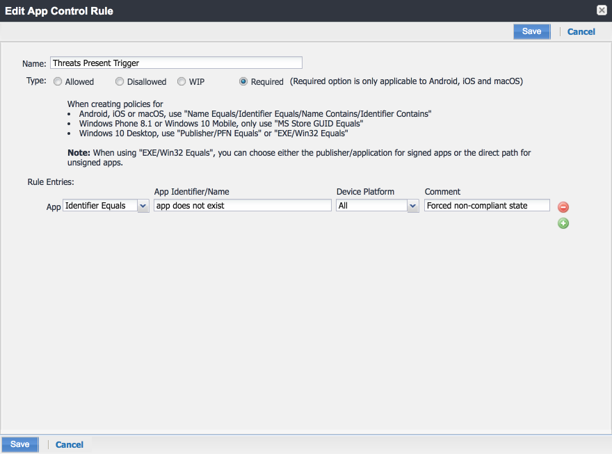
The new app control rule should now appear on the Apps > App Control page.
Figure ‑ MobileIron App Control Rule
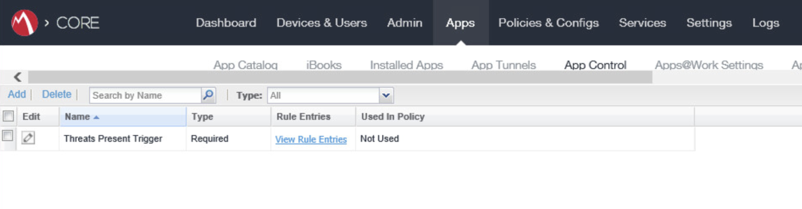
2.7.7.2 Add MobileIron Compliance Actions
A Compliance Action defines what actions MobileIron will take when an App Control policy, like the one created in the previous section, is violated by a managed mobile device. The following steps will create and configure an example Compliance Action in response to the MTP - High Risk App Control rule. Note that a single Compliance Action can be associated with multiple App Control rules if the same response would be configured for each. Otherwise, a new Compliance Action should be created.
In the MobileIron Admin Portal, navigate to Policies & Configs > Compliance Actions.
Select Add; the Add Compliance Action dialogue opens.
In the Add Compliance Action dialogue:
In the Name field, add a description of the compliance action; we recommend indicating the kind of action taken. This example illustrates creating a compliance action that will be associated with the MTP - High Risk label.
Select the Enforce Compliance Actions Locally on Devices check box.
Select the Send a compliance notification or alert to the user check box.
Select the Block email access and AppConnect apps check box.
Select the Quarantine the device check box.
Deselect the Remove All Configurations check box.
Click Save.
Figure 2‑124 MTP High Risk Compliance Action
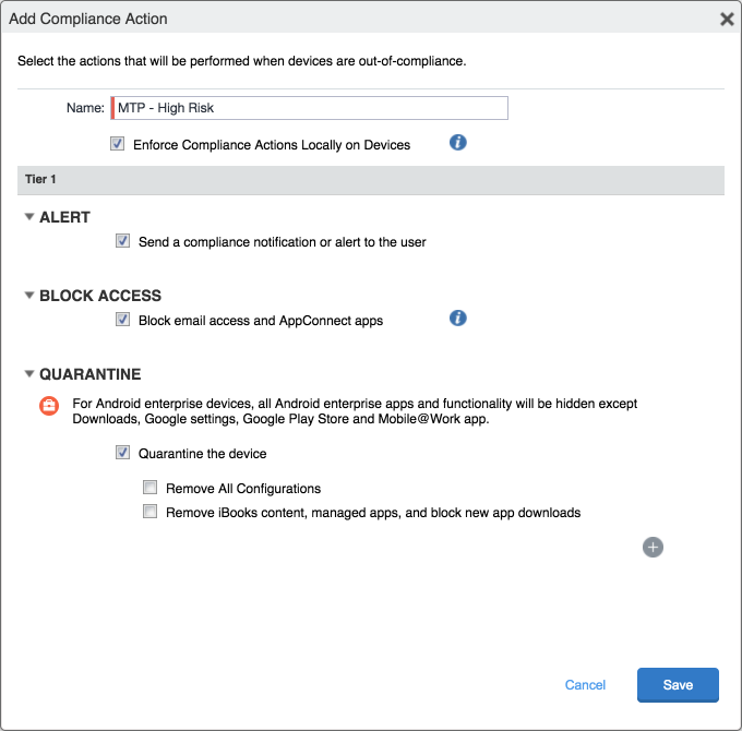
2.7.7.3 Create MobileIron Security Policy for Lookout MES
In addition to potentially defining other controls, such as password requirements, a Security Policy can map a Compliance Action to an App Control rule, enabling MobileIron to execute the configured actions whenever a device that applies the policy violates the App Control rule. The following steps will create a new Security Policy for Lookout MES High Risk devices using an existing policy as a baseline from which to apply more stringent controls.
In the MobileIron Admin Portal, navigate to Policies & Configs > Policies.
On the Policies page:
Select the security policy to use as a baseline.
Select More Actions > Save As; this opens the New Security Policy dialogue.
Figure 2‑125 Baseline Policy Selection
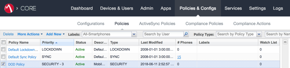
In the New Security Policy dialogue:
In the Name field, rename the policy to MTP - High Risk.
In the Priority drop-down menu, select a current policy. The new policy will be prioritized based on the selection. In this example, the new policy is higher than the MTP Medium Risk policy. Note: for ease of setting priority, it is recommended to add new security policies in ascending order (lowest to highest priority).
Figure 2‑126 MTP High Risk Policy
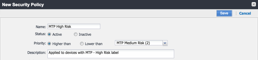
Under Access Control > For All Platforms section:
1. For the when a device violates the following app control rules drop-down menu, select the MTP - High Risk compliance action.
2. In the Available list of app control rules, highlight MTP High Risk Trigger.
3. Select the right arrow to move MTP High Risk Trigger item into the Enabled List.
Click Save.
Figure 2‑127 Security Policy Trigger
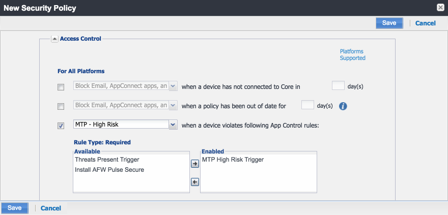
2.7.7.4 Apply Lookout MES Label to MobileIron Security Policy
The following steps will apply the MTP - High Risk label to the security policy created in the previous section. As a result, once the Lookout cloud service applies the label to any device with a detected high-risk threat and such a device checks in with MobileIron, the security policy will automatically be applied to it (provided it is of higher priority than the policy currently applied). In turn, that will cause the MTP High Risk Trigger App Control policy to be violated and the MTP - High Risk Compliance Action to be taken. Once Lookout detects that the threat has been resolved, the Lookout service will remove the MTP - High Risk label, and on device check-in, MobileIron will then apply the next-lower-priority security policy.
In the MobileIron Admin Portal, navigate to Policies & Configs > Policies.
On the Policies page:
Select the check box in the MTP High Risk security policy item.
Select More Actions > Apply to Label; the Apply to Label dialogue opens.
Figure 2‑128 Policy List
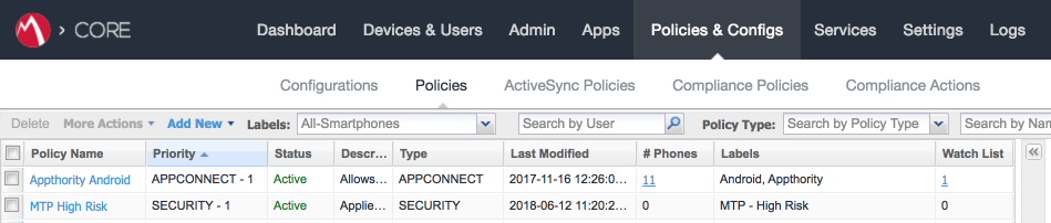
In the Apply to Label dialogue:
Select the check box for the MTP - High Risk item.
Select Apply.
Figure 2‑129 Apply To Label Dialogue
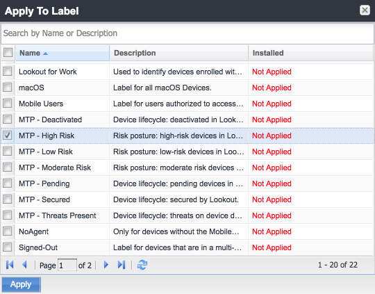
2.8 Integration of Appthority Mobile Threat Detection with MobileIron
Appthority provides an on-premises connector for MobileIron that runs as a Docker container on RedHat Linux. The connector uses the MobileIron API to obtain information on managed devices and their installed apps, which is then synchronized with the cloud service instance to obtain app and device risk scores, which are assigned to devices using custom attributes. The following sections provide the steps to create a MobileIron API account and deploy and configure the Appthority connector.
2.8.1 Create MobileIron API Account for Appthority Connector
The following steps will create an administrative account that will grant Appthority the specific permissions it requires within MobileIron.
In the MobileIron Admin Portal, navigate to Devices & Users > Users.
On the Users page:
Select Add > Add Local User; the Add New User dialogue opens.
In the Add New User dialogue:
In the User ID field, enter the user identity the Appthority connector will authenticate under. Our implementation uses a value of Appthority.
In the First Name field, enter a generic first name for Appthority.
In the Last Name field, enter a generic last name for Appthority.
In the Display Name field, optionally enter a displayed name for this user account.
In the Password field, provide the password the Appthority identity will use to authenticate to MobileIron.
In the Confirm Password field, enter the same password as in the preceding step.
In the Email field, provide an email account for the Appthority identity; this should be an account under the control of your organization.
Click Save.
Figure 2‑130 Appthority User Settings
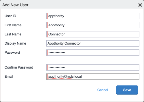
In the MobileIron Admin Portal, navigate to Admin.
On the Admin page:
Enable the account you created for Appthority during Step 2.
Select Actions > Assign to Space; this opens the Assign to Space dialogue for the Appthority account.
Figure 2‑131 Appthority Connector User
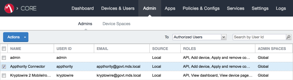
In the Assign to Space dialogue:
In the Select Space drop-down menu, select Global.
Figure 2‑132 Appthority Connector Space Assignment
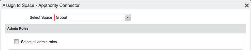
Enable each of the following settings:
Device Management > View device page, device details |
Privacy Control > View apps and ibooks in device details |
App Management > Apply and remove application label |
Other Roles > API |
Click Save.
2.8.2 Deploy Appthority Connector Open Virtualization Appliance
One deployment option for the Appthority connector is a pre-built RedHat virtual machine distributed as an Open Virtualization Appliance (OVA). We imported the OVA into our virtual lab environment following guidance provided in Connector On-Premises: Virtual Machine Setup available from the Appthority support portal: https://support.appthority.com/.
2.8.3 Run the Enterprise Mobility Management Connector Deployment Script
Once the Appthority docker container is running, the setup script will configure it to use the MobileIron API account created previously. Detailed instructions on using the script are available on the Appthority support portal at https://help-mtp.appthority.com/SetUp/EMM/EMM_Script/RunEMMDeployScript.html. The first two steps ask for Appthority-supplied credentials necessary to verify your subscription and to link the connector with the correct instance of their cloud service. In the third step you will provide details to integrate with your on-premises instance of MobileIron core. Our results from completing the third step are shown below.
Obtain a copy of Run the EMM Connector Deployment Script from the Appthority support portal at https://help-mtp.appthority.com/SetUp/EMM/EMM_Script/RunEMMDeployScript.html (authentication to the portal is required).
Execute the script. The third step in the script involves providing settings to enable the Appthority Connector to communicate with MobileIron Core. The results of our completion of that step are provided below as a reference.
Figure 2-133 Appthority Connector CLI Configuration
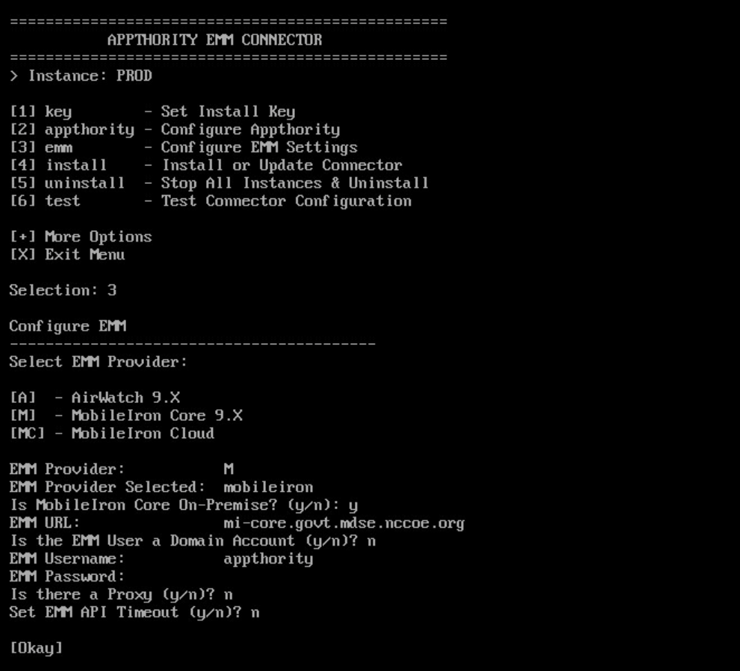
Once the script has been completed, verify successful synchronization with the Appthority cloud service by accessing the Appthority MTP portal and navigating to Admin > EMM and viewing items under Connector Status.
Figure 2‑134 Appthority EMM Connector Status
2.9 Registering Devices with MobileIron Core
In this scenario, the employee manages their own personal apps, data, and many device functions. The organization manages work-related apps and data, and has control over specific device functions, such as requiring a complex device unlock PIN or being able to remotely wipe a lost device. The mechanisms to achieve similar security characteristics between iOS and Android devices differ.
2.9.1 Supervising and Registering iOS Devices
Many MDM-based security controls are only applicable to iOS devices that are running in Supervised Mode. The following steps outline how to place an iOS device into this mode, and then register with MobileIron Core.
2.9.1.1 Resetting the iOS Device
Before a device can be placed into Supervised Mode, it must be in a factory-reset state with the Activation Lock on the device removed. If Activation Lock is in-place, Configurator 2 will be unable to place the device into Supervised Mode.
2.9.1.1.1 Reset an Unsupervised Device Using Settings App
If a device is not already in Supervised Mode, it is recommended to have the current device user manually reset and activate the device to factory settings using the following steps:
Navigate to Settings > General > Reset.
Select Erase All Content and Settings.
Figure 2‑135 iOS Reset Screen
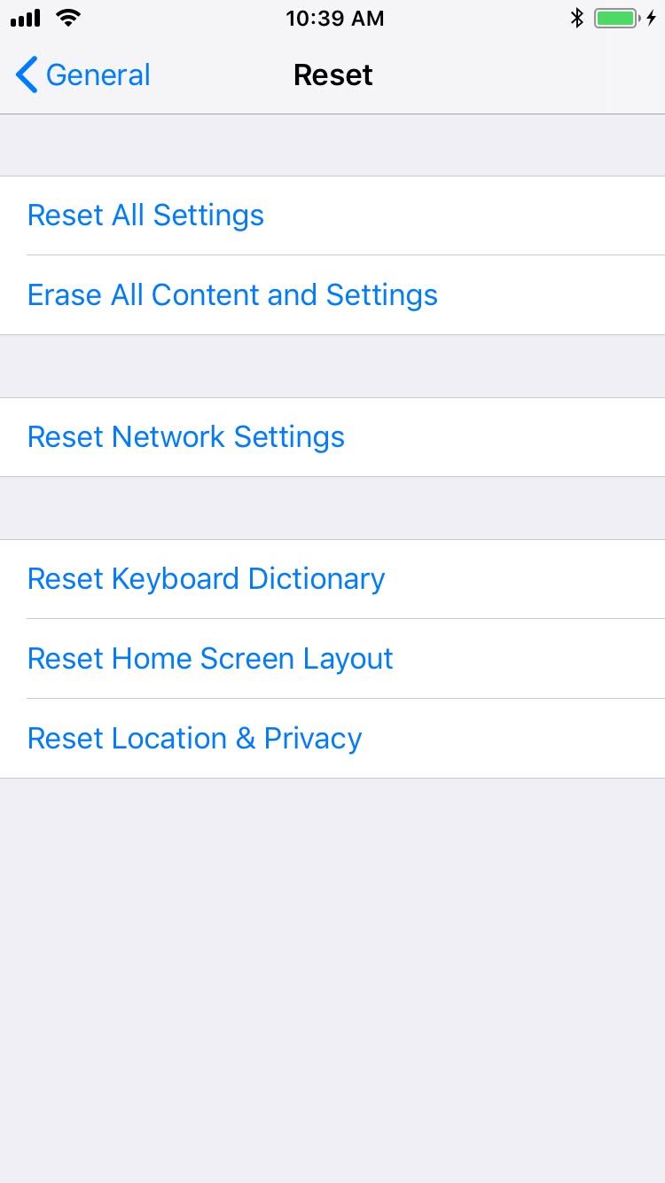
At the warning that this will delete all media and data and reset all settings, select Erase iPhone.
Figure 2‑136 Erase iPhone Confirmation
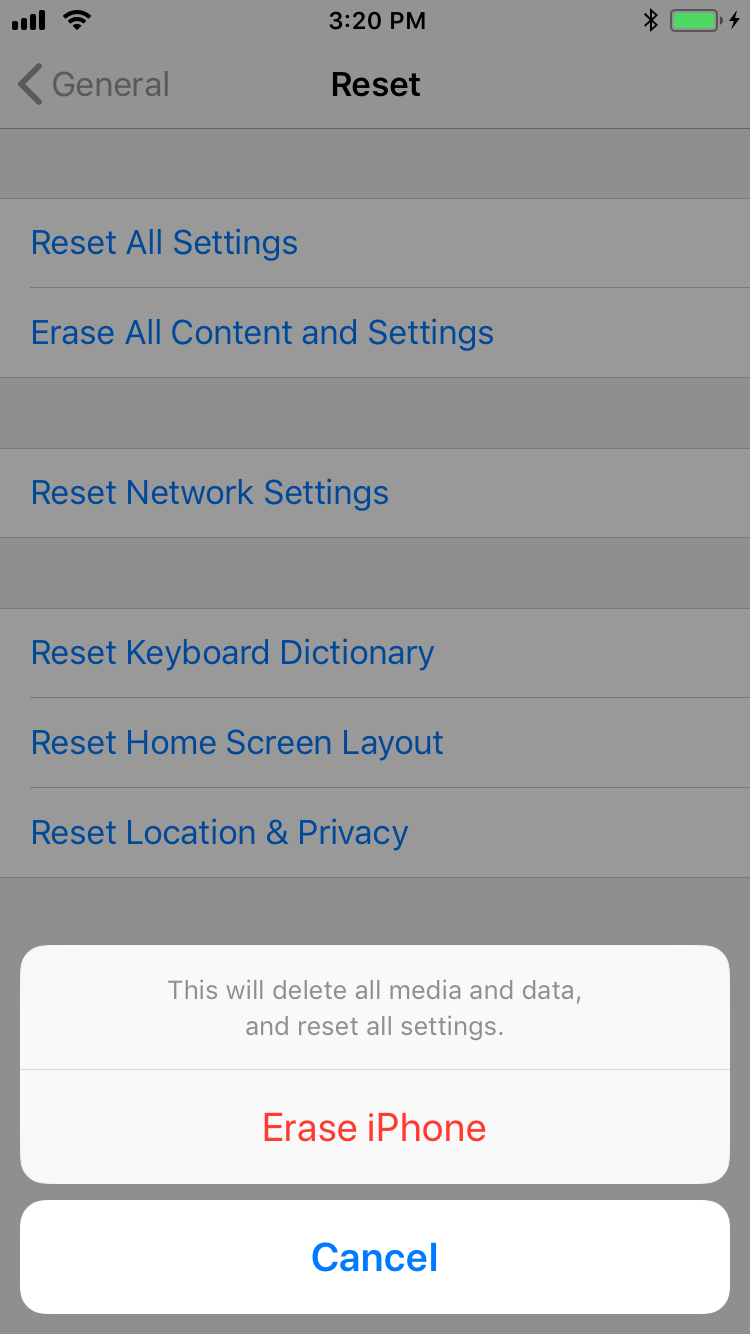
At the warning that all media, data, and settings will be irreversibly erased, select Erase iPhone. Once the reset process is complete, the device will reboot and need to be activated.
Figure 2‑137 Erase iPhone Final Confirmation
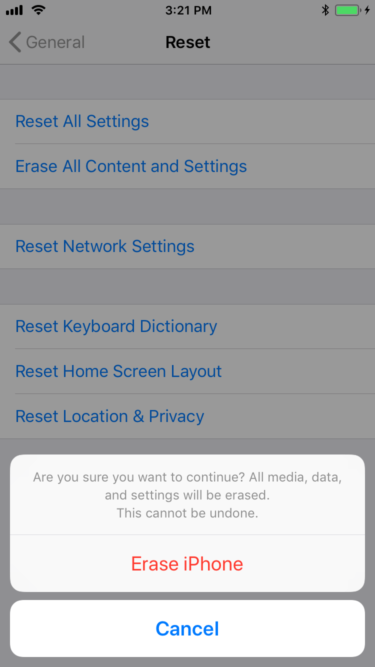
Once the device displays the Hello screen, press the Home key.
At the Select Your Language screen, select English.
At the Select Your Country or Region screen, select United States.
At the Quick Start screen select Set up Manually.
At the Choose a Wi-Fi Network screen, select the Service Set Identifier (SSID) for the network and authenticate to your on-premises SSID Wi-Fi network; the device should indicate it is being activated. Note: you may need to attempt activation again if there is a delay in the device establishing connectivity to the internet.
Stop at the Data & Privacy screen. At this point, the device should be placed into Supervised Mode using Configurator 2.
2.9.1.1.2 Reset a Supervised Device Using Configurator 2
Connect the iOS device with the system running Configurator 2 over Universal Serial Bus (USB).
On the device at the Enter Passcode screen (if locked), enter the device unlock passcode.
Figure 2‑138 Entering iOS Passcode
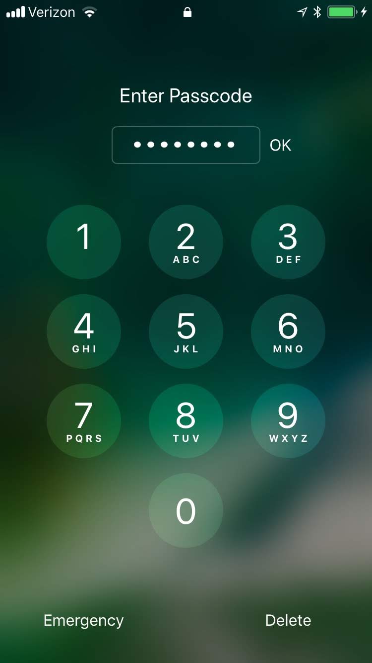
At the Trust this Computer? dialogue, select Trust. Note that this step, along with step that follows, is only encountered the first time a device is paired with a given system.
Figure 2‑139 iOS Trust Computer Confirmation
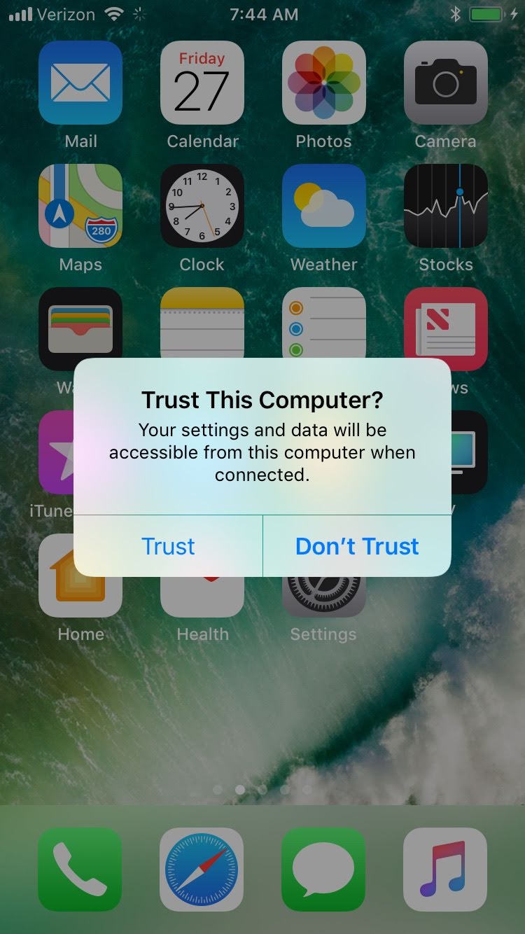
At the Enter Device Passcode to Trust This Computer screen:
Enter the device unlock passcode.
Click OK.
Figure 2‑140 Entering Passcode to Trust Computer
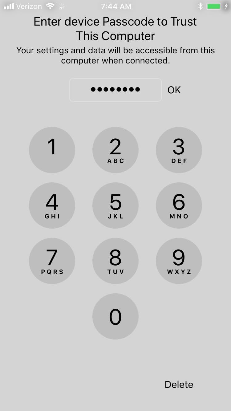
In Configurator 2, select the representation of the connected device.
From the context menu, select Advanced > Erase All Content and Settings.
At the Are you sure you want to erase “<device name>”? dialogue, select Erase.
Figure 2‑141 Configurator 2 Erase Confirmation
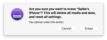
At the License Agreement screen:
Review the license agreement.
Select Accept to agree to the license and continue using the software.
Configurator 2 will take several minutes to restore the device to factory default settings. Configurator 2 will also activate the device following restoration.
Figure 2‑142 Restoring iPhone
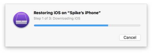
2.9.1.2 Placing an iOS Device into Supervised Mode
iOS devices that have been factory reset and subsequently activated (the Activation Lock has been removed) can be placed into Supervised Mode using software available from Apple, Configurator 2, by the following steps:
Pair the target iOS device with the system running Configurator 2 over USB.
Navigate to Configurator 2 > Unsupervised; a representation of the connected device should appear.
On the All Devices tab:
Select the representation of the paired device.
From the context menu, select Prepare; a wizard opens to guide the process.
For the Prepare Devices step:
Enable Supervise Devices.
Select Next.
Figure 2‑143 Device Preparation Options
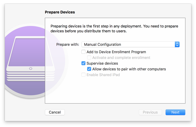
For the Enroll in MDM Server step:
Ensure the Server drop-down menu has Do not enroll in MDM selected.
Select Next.
Figure 2‑144 MDM Server Selection
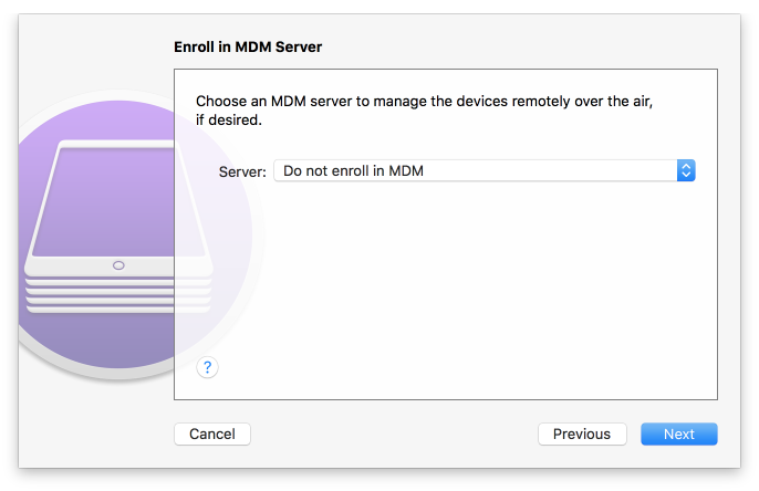
For the Sign into the Device Enrollment Program step, select Skip.
Figure 2‑145 Signing into Apple Account
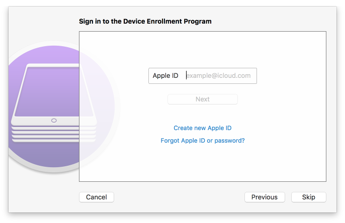
For the Assign to Organization step:
If you have previously created your organization, select Next and continue with Step 9.
If you have not created your organization, from the Organization drop-down menu, select New Organization…
Figure 2‑146 Organization Assignment Dialogue
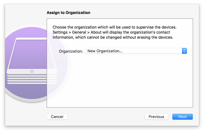
At the Create an Organization screen:
In the Name field, enter the name of your organization.
In the Phone field, enter an appropriate support number for your mobility program
In the Email field, enter an appropriate support email for your mobility program
In the Address field, enter the address for your organization
Select Next.
Figure 2‑147 Creating an Organization
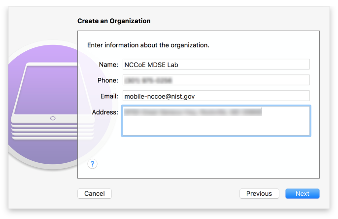
If your organization has established a digital identity for placing devices into Supervised Mode:
Continue with Step 10. Note: that the same digital identity must be used for any given device.
Otherwise, continue with Step 14.
In the Create an Organization screen:
For the Generate or choose a supervision identity option, select Choose an existing supervision identity.
Select Next.
Figure 2‑148 Supervisory Identity Configuration
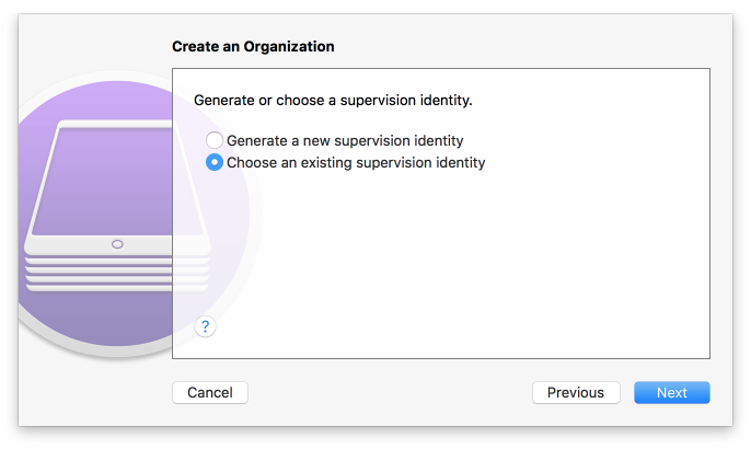
Select Choose…
Figure 2‑149 Organization Selection
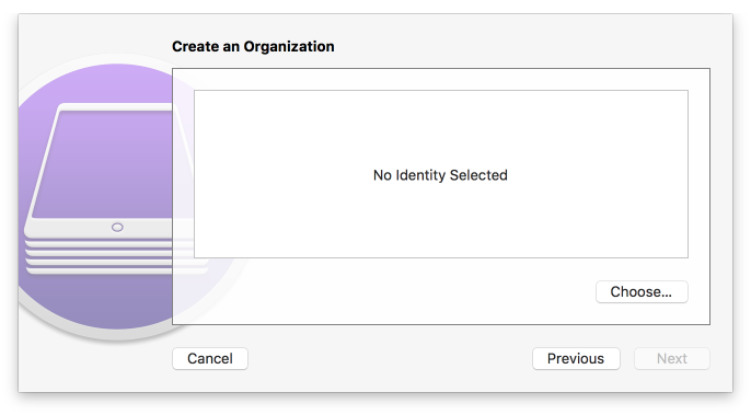
At the Choose a supervising identity for the organization dialogue:
Select the digital certificate from the list of those available to the system.
Select Choose.
Figure 2‑150 Supervising Identity Selection
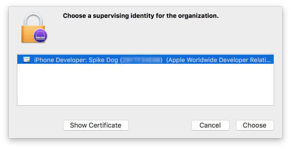
At the Create an Organization screen, select Next.
Figure 2-151 Selected Organization
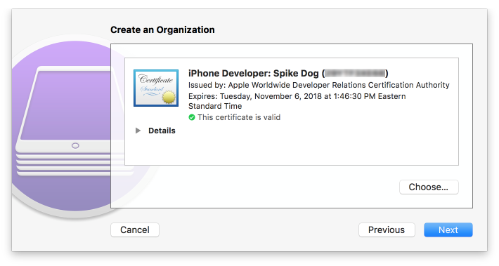
In the Create an Organization screen:
For the Generate or choose a supervision identity option, select Generate a new supervision identity.
Select Next.
Figure 2‑152 Create an Organization Supervision Identity Configuration

For the Configure iOS Setup Assistant step:
Ensure the Setup Assistant drop-down menu shows Show only some steps selected; additional options will appear.
Enable each of the Privacy, Passcode, Apple ID, and Location Services check-boxes.
Select Prepare.
Figure 2‑153 Setup Assistant Configuration
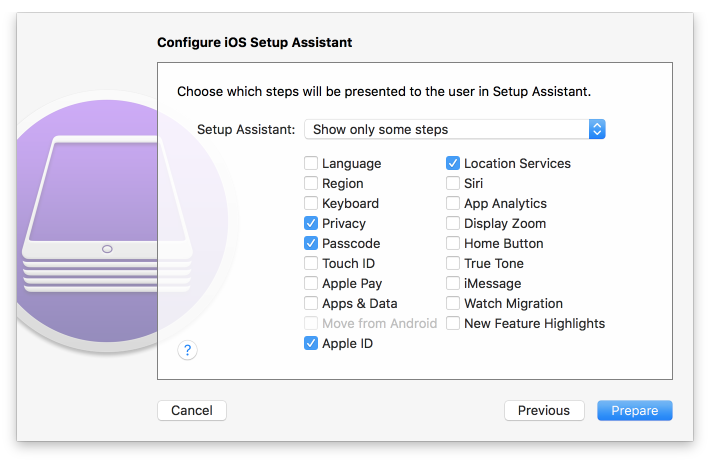
Configurator 2 will take several minutes to prepare the device and place it into Supervised Mode.
Figure 2‑154 Waiting for iPhone
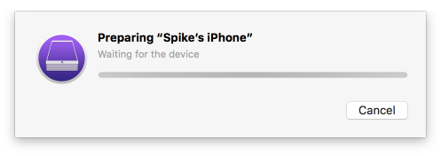
2.9.1.3 Registration with MobileIron Core
The following steps will register an iOS device in Supervised Mode with MobileIron Core, which uses a web-based process rather than the Mobile@Work app.
Using Safari, navigate to the MobileIron Core page, substituting <FQDN> for your organization’s instance of MobileIron Core. In our example implementation, the resulting URL is https://mi-core.govt.mdse.nccoe.org/go.
Figure 2‑155 iOS Device MobileIron Registration Page
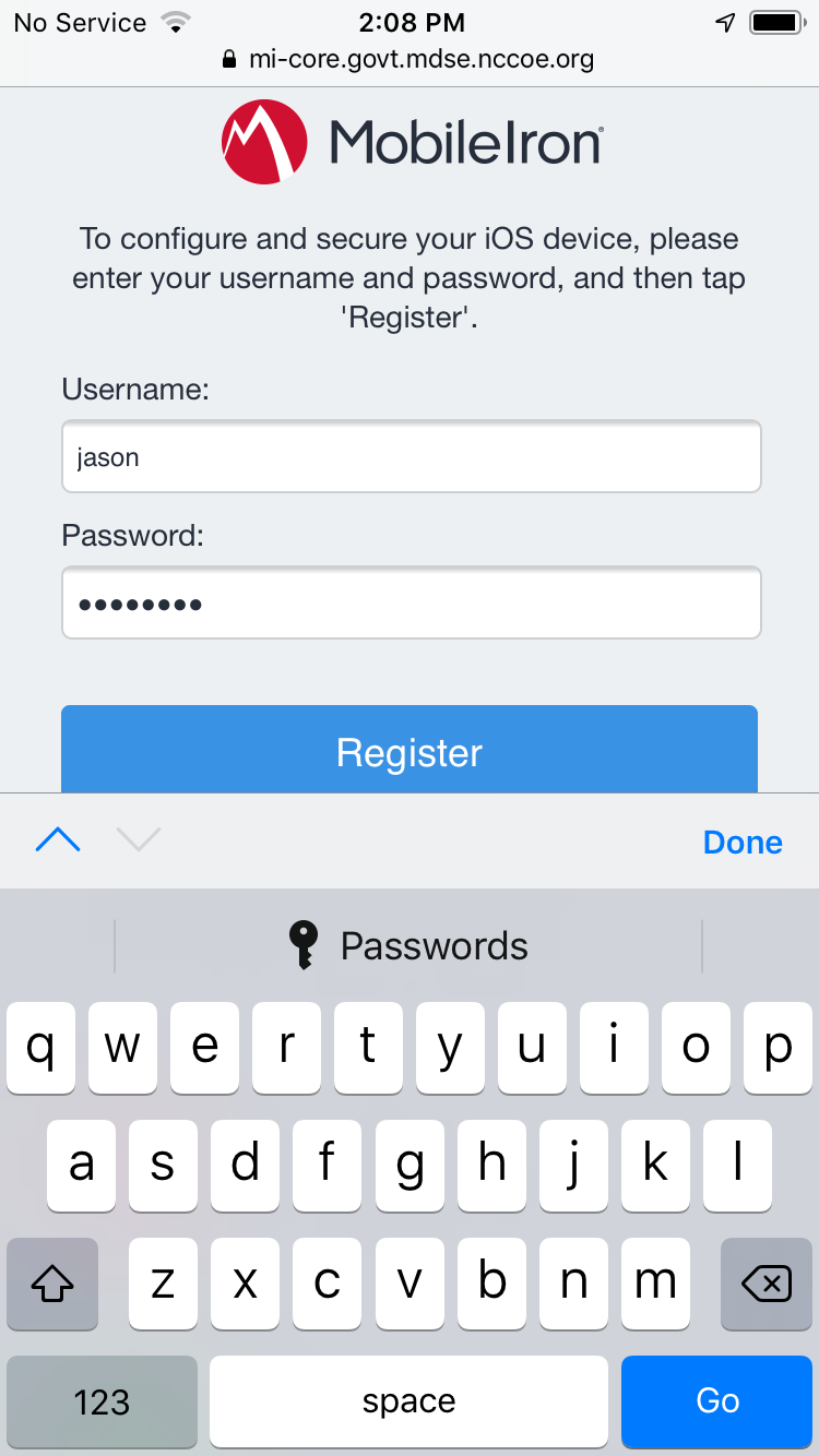
At the warning that the web site is trying to open Settings to show a configuration profile, select Allow; the Settings built-in app opens.
Figure 2‑156 Opening Settings Confirmation
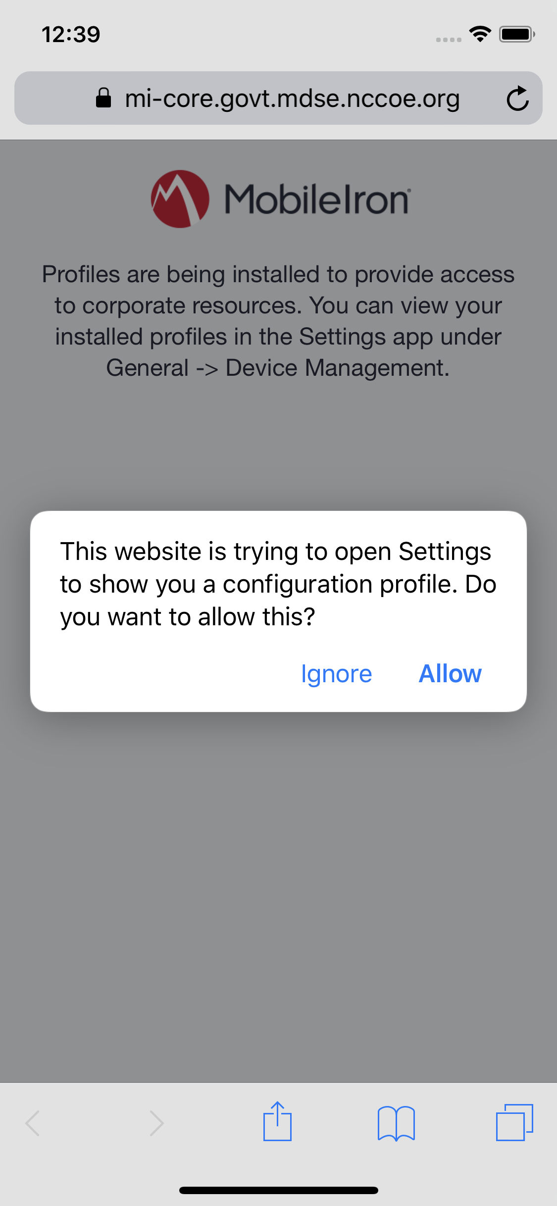
At the Settings > Install Profile screen:
Verify the Signed by field indicates the server identity is Verified.
Select Install.
Figure 2‑157 Profile Installation
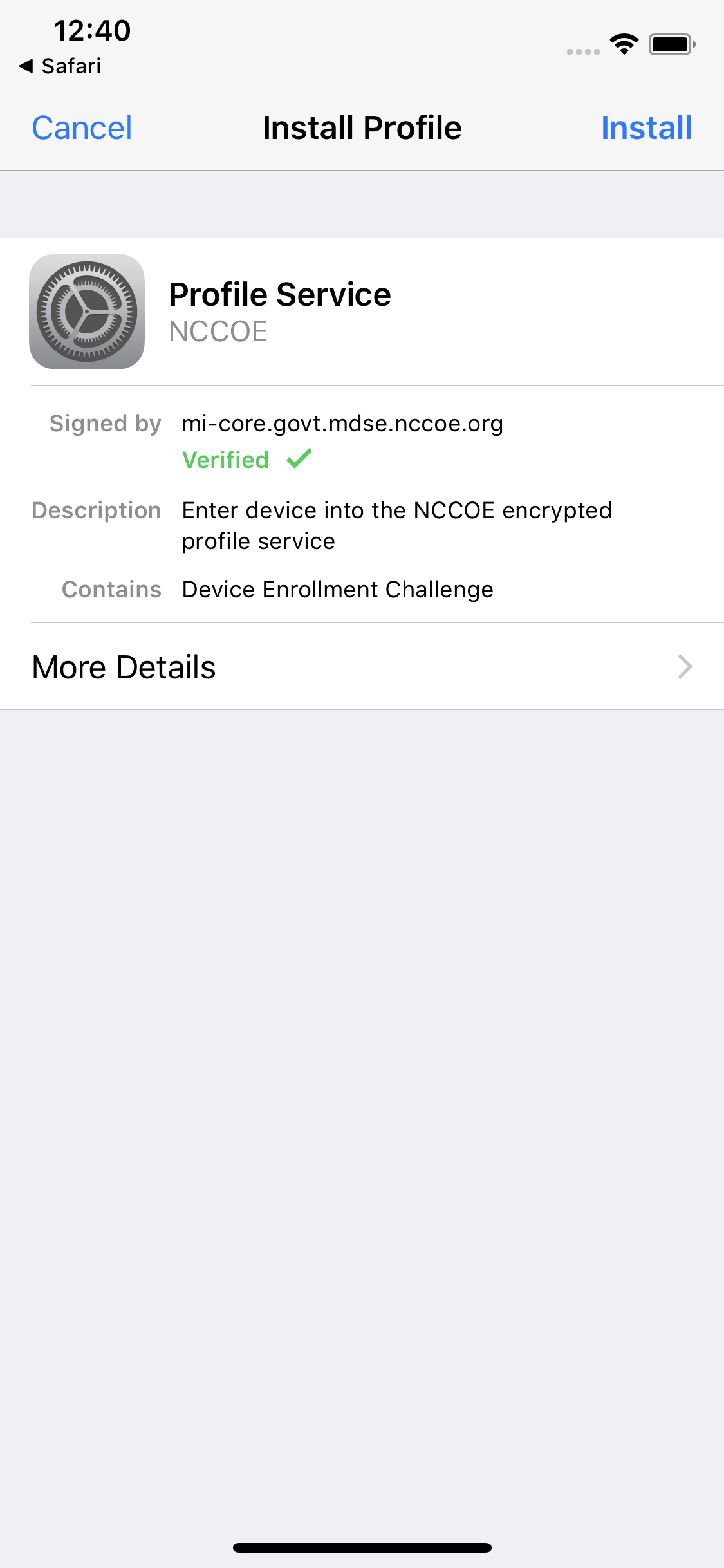
At the Installing Profile screen, select Install.
Figure 2‑158 Profile Installation
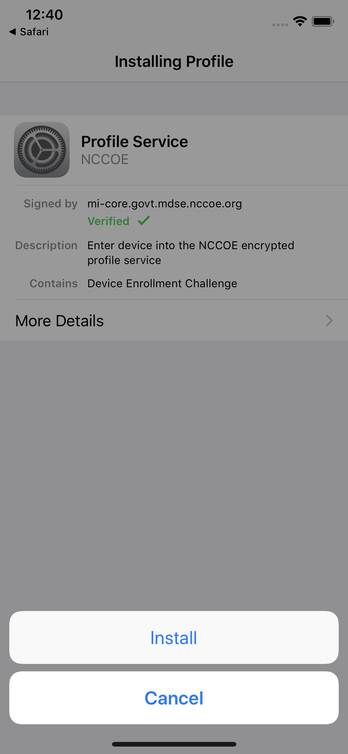
At the Warning screen:
Verify that information under Root Certificate and MDM is consistent with information provided by your mobile device administrator.
Select Install.
Figure 2‑159 Profile Installation Warning
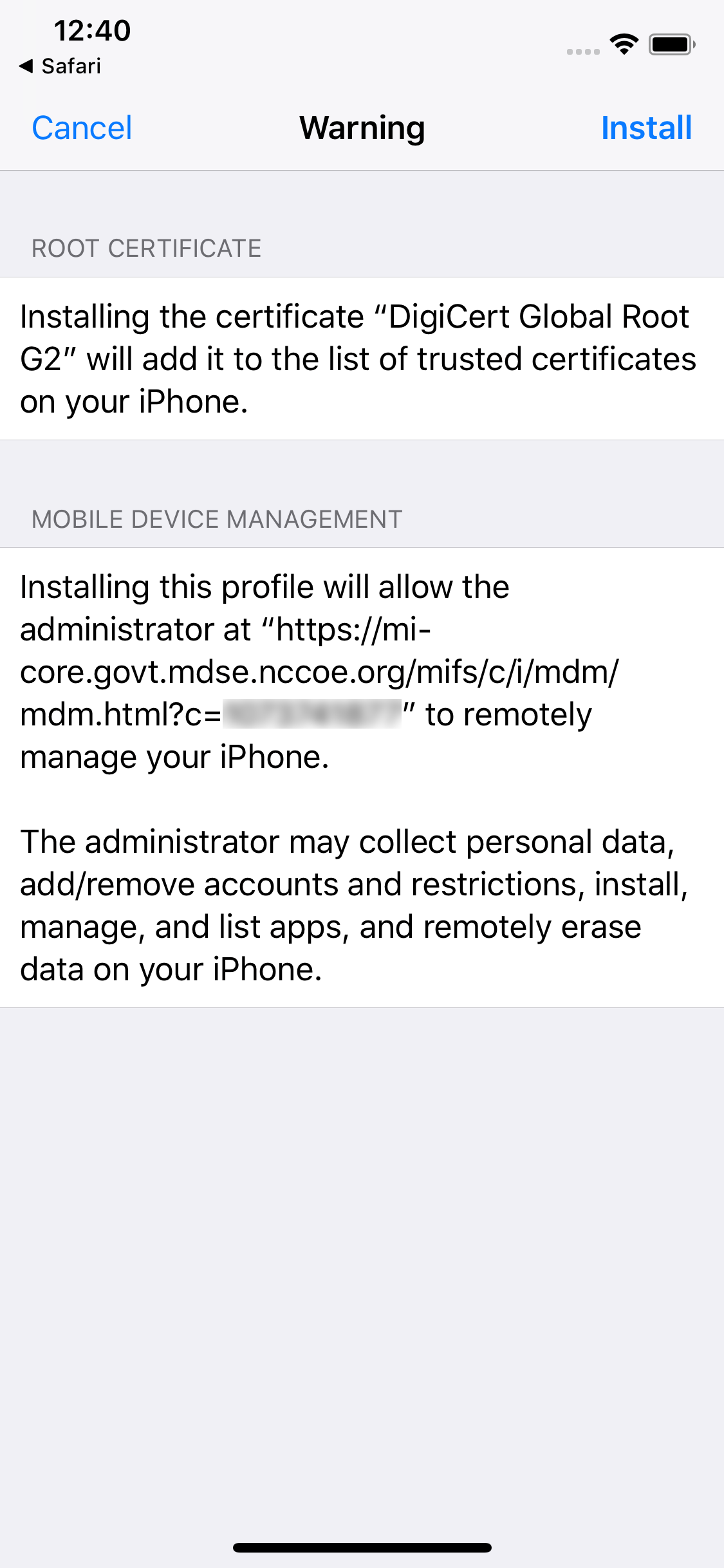
In the Remote Management dialogue, select Trust.
Figure 2‑160 Profile Installation Trust Confirmation

At the Profile Installed screen, select Done. The device is now registered with MobileIron.
Figure 2‑161 Profile Installation Confirmation
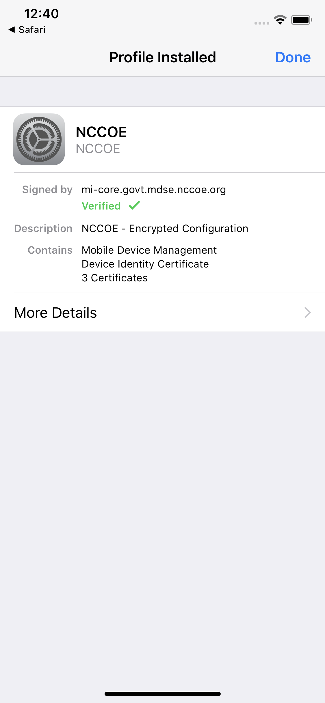
2.9.2 Activating Lookout for Work on iOS
The configuration of the Lookout for Work (iOS) app in the MobileIron app catalogue causes a configuration file to be included during the automatic install.
Upon launching the app, additional action is required to grant Lookout for Work the permissions necessary for it to provide optimal protection.
Launch the Lookout for Work app; activation occurs silently at the splash screen.
Figure 2‑162 Lookout for Work Splash Screen

At the welcome screen, select Continue.
Figure 2‑163 Lookout for Work Permission Information
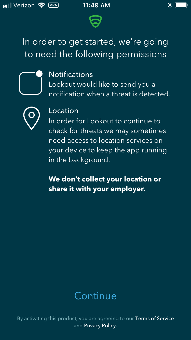
At the “Lookout Work” Would Like to Send You Notifications dialogue, select Allow.
Figure 2‑164 Notifications Permissions Prompt
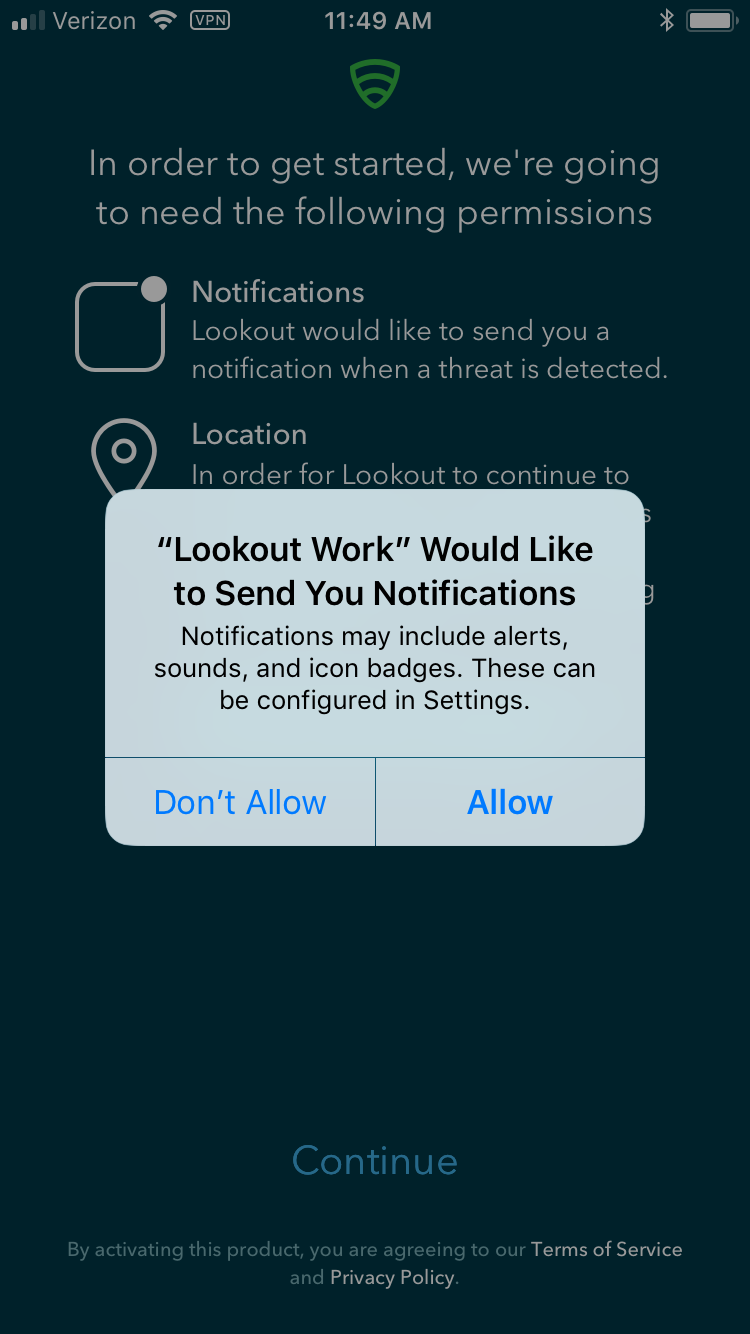
At the Allow “Lookout Work” To Access Your Location? dialogue, select Always Allow.
Figure 2‑165 Locations Permission Prompt
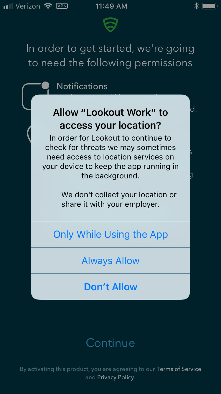
Lookout for Work should automatically perform scans of device and app activity and provide feedback to the user.
Figure 2‑166 Lookout for Work Home Screen
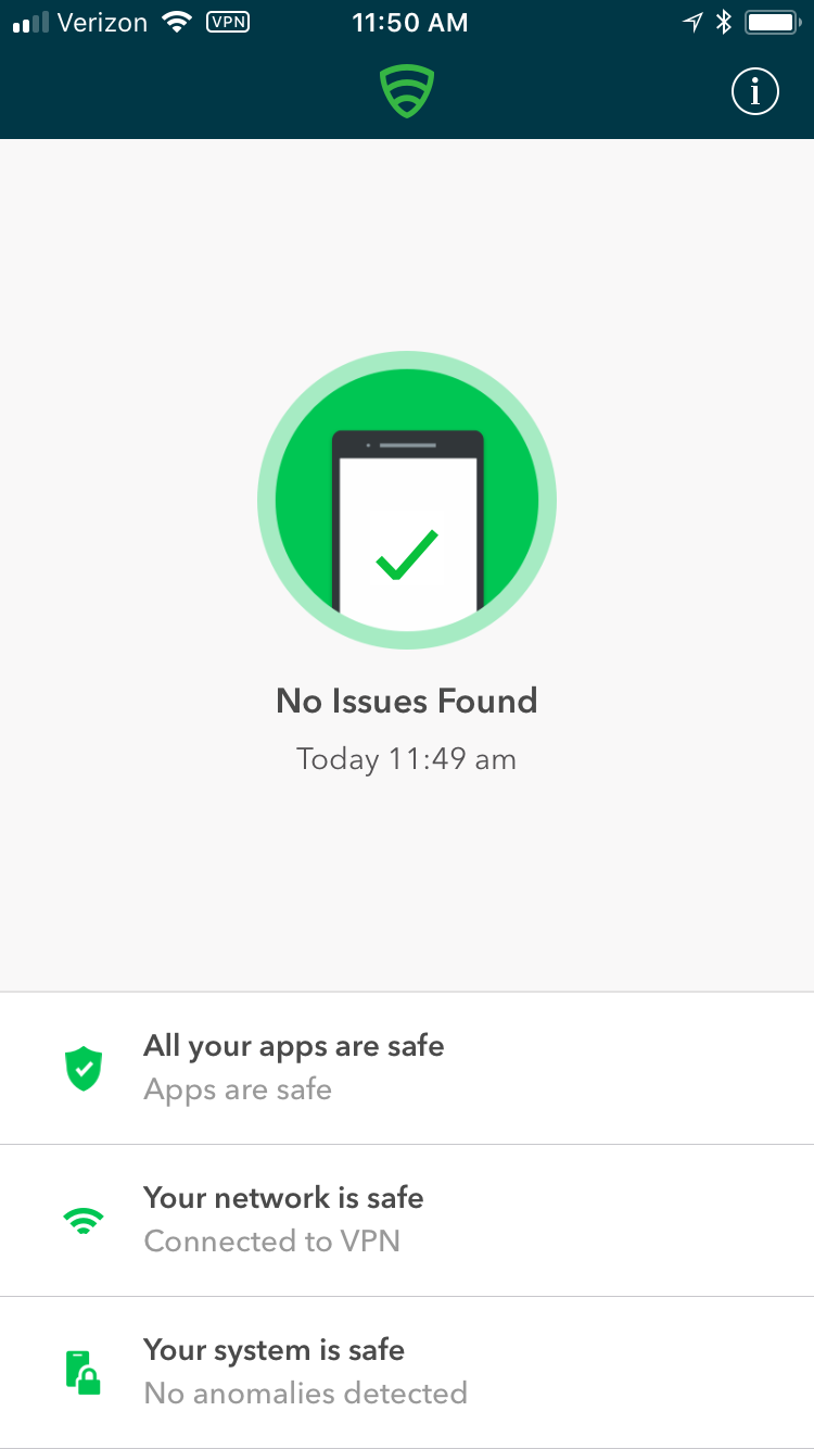
2.9.3 Provisioning Work-Managed Android Devices with a Work Profile
In this scenario, Android devices are deployed as work-managed with a work profile. Enabling this feature for AFW-capable devices requires a change to the AFW configuration. It also requires that the device user already has a personal Google account to provision the work profile; it is not created as part of the workflow to register a device with MobileIron Core.
2.9.3.1 Enable Work Profile on Work-Managed Devices
In the MobileIron Admin Portal, navigate to Policies > Configs > Configurations.
Enable the check box in the row for the AFW configuration.
In the Configuration Details pane, select Edit.
Figure 2‑167 MobileIron AFW Configuration
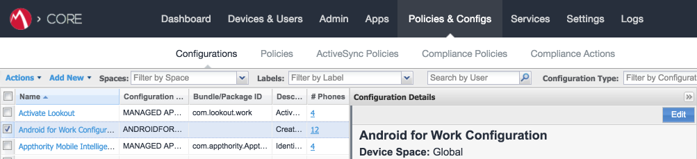
In the Edit Android enterprise (all modes) Setting dialogue:
Enable Enable Managed Devices with Work Profile on the devices.
Enable Add Google account.
In the Google Account text box, provide a valid Google domain account. The example in our reference implementation will map a MobileIron user ID of gema to an email address of mdse.gema@gmail.com. This needs to be done for each user. See MobileIron Core 9.4.0.0 Device Management Guide for AFW for a list of variables to appropriately adapt this field to your existing identity management strategy.
Click Save.
Figure 2‑168 AFW Configuration
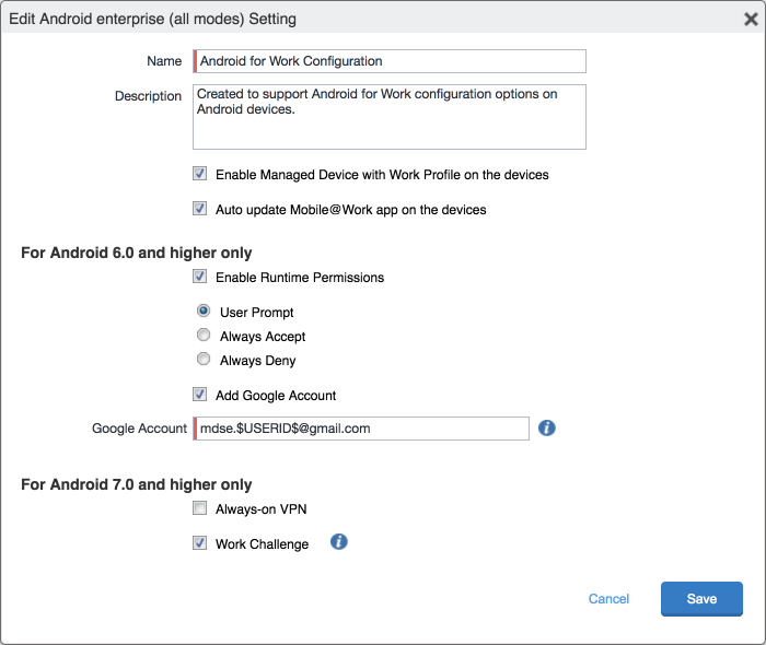
2.9.3.2 Registering Android Devices
The following steps can only be completed when working with an Android device that is still set to (or has been reset to) factory default settings.
When prompted to sign in with your Google Account:
In the Email or phone field, enter afw#mobileiron.core.
Select Next.
Figure 2‑169 MobileIron Enrollment Process
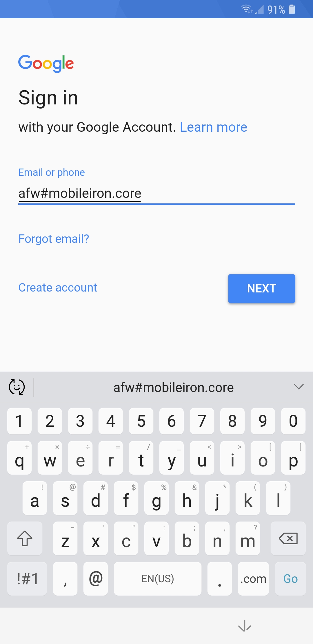
- When AFW prompts you to install Mobile@Work, select Install; this downloads theMobile@Work client to the device.
Figure 2‑170 AFW Enrollment
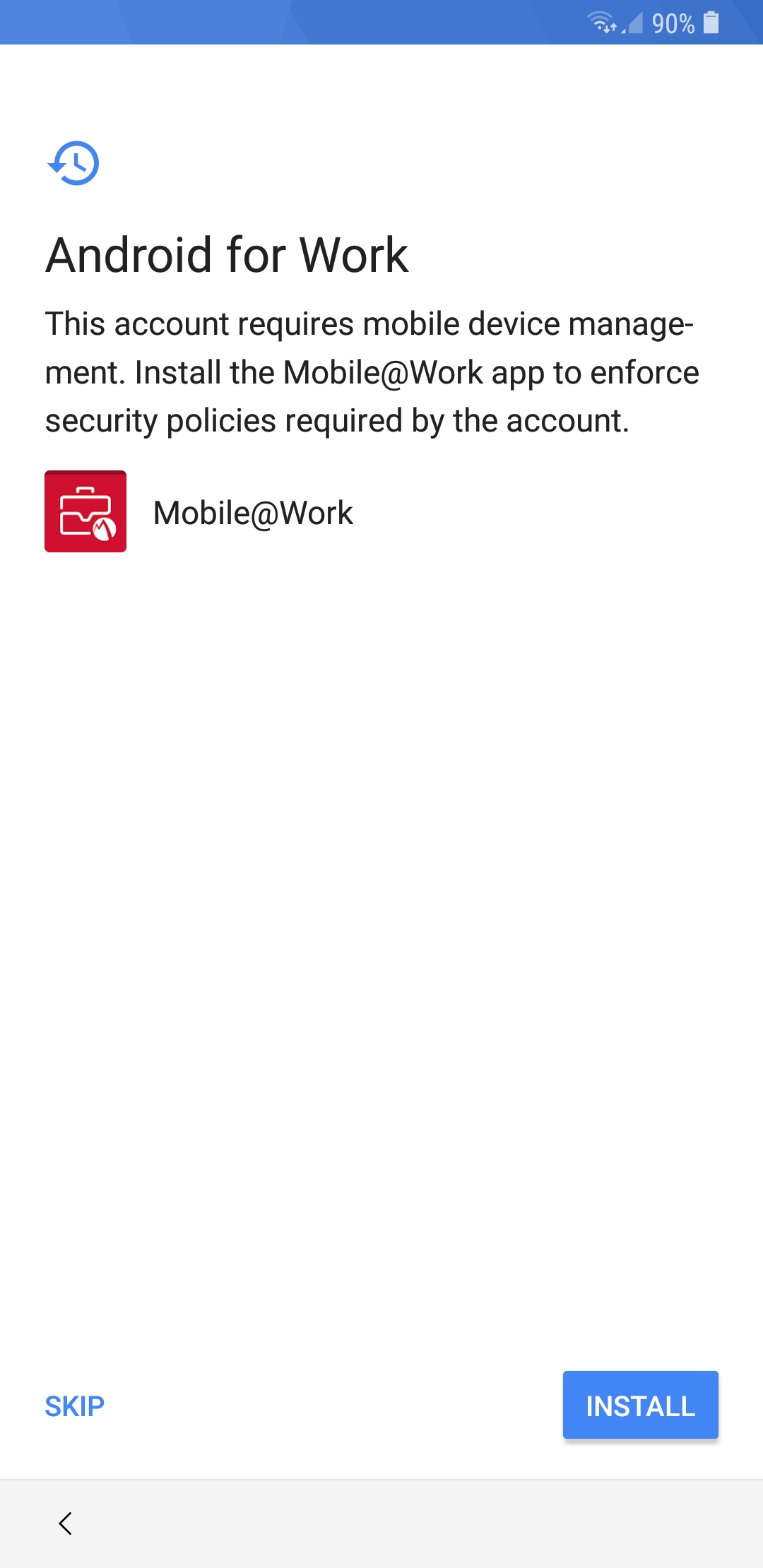
At the prompt to install MobileIron, select Install.
Figure 2‑171 MobileIron Installation
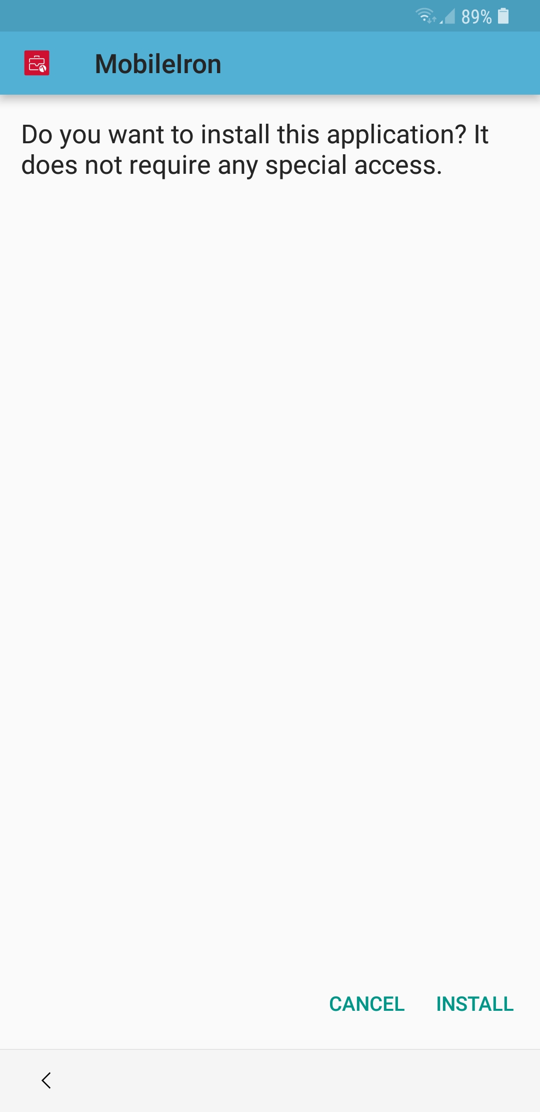
At the Set up your device screen, select Accept.
Figure 2‑172 Accepting AFW Terms and Conditions
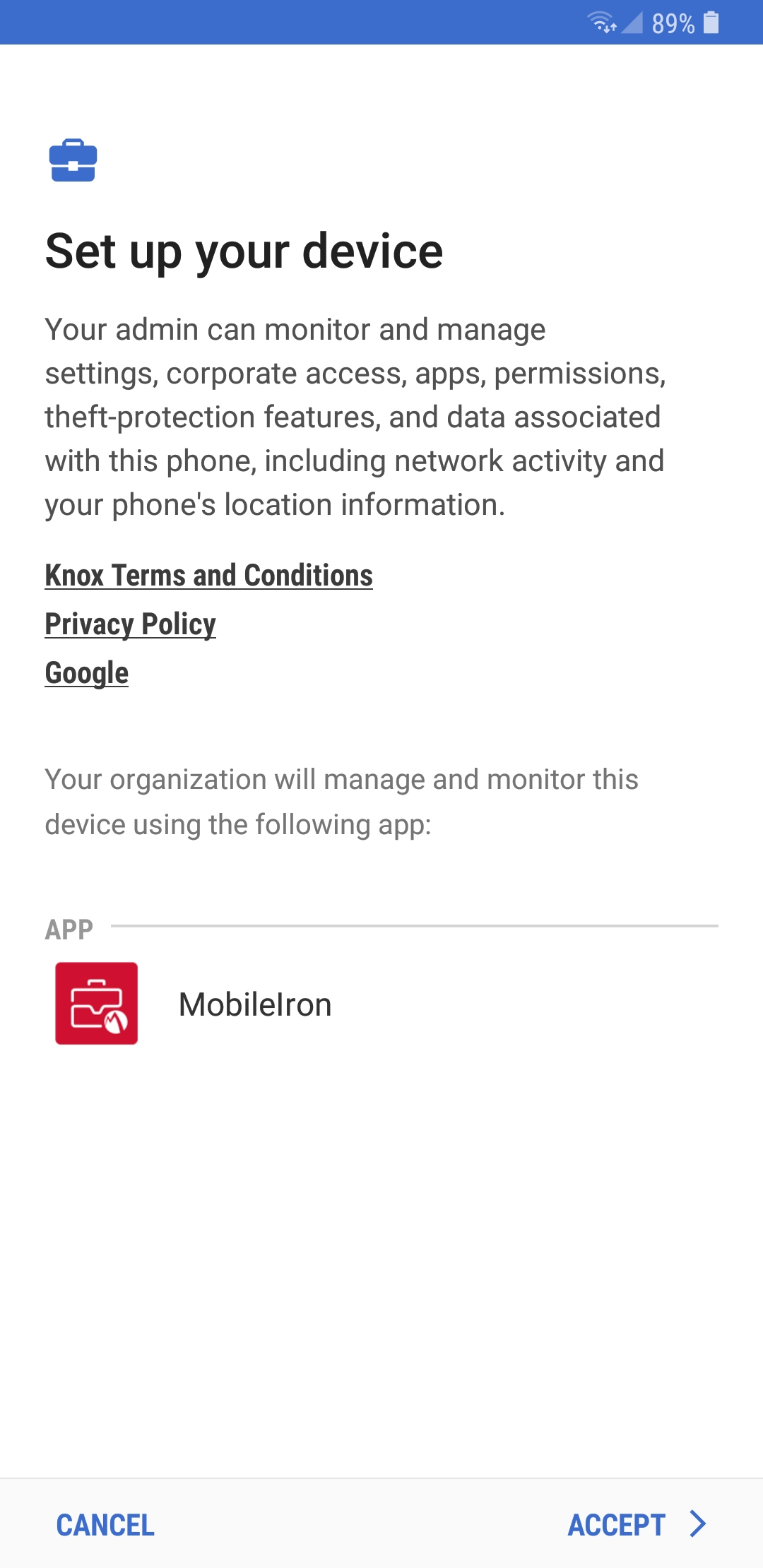
This screen notifies the user of the data that Mobile@Work collects and how it is used. When this information has been reviewed, select Accept. Mobile@Work minimizes and returns to the operating system home screen.
Figure 2‑173 MobileIron Privacy Information
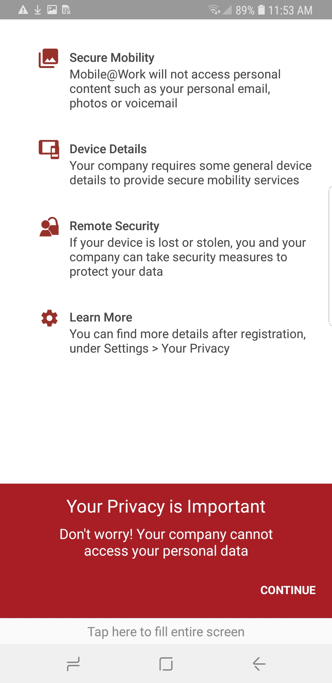
When MobileIron sends a Configuration Required notification, select the notification.
Figure 2‑174 MobileIron Configuration Required Notification
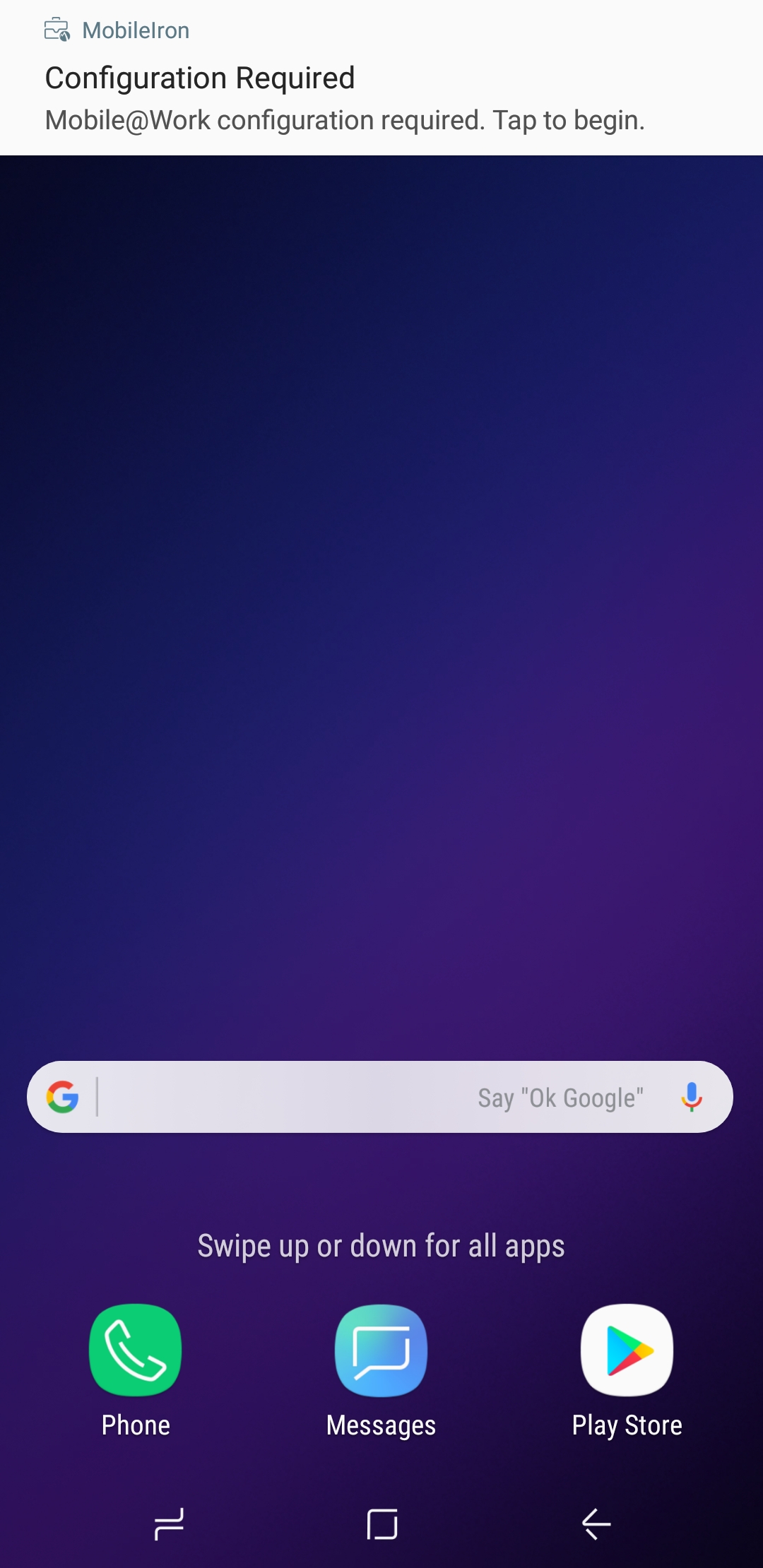
On the Device Status > Create Work Profile screen, select Continue.
Figure 2‑175 MobileIron Device Status
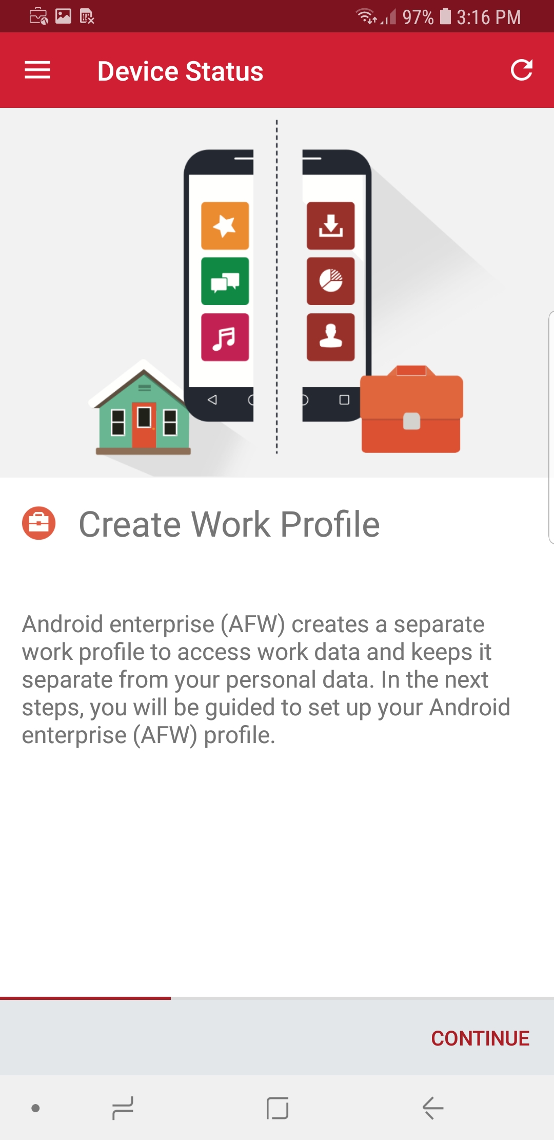
At the AFW prompt, select Continue.
Figure 2‑176 AFW Configuration
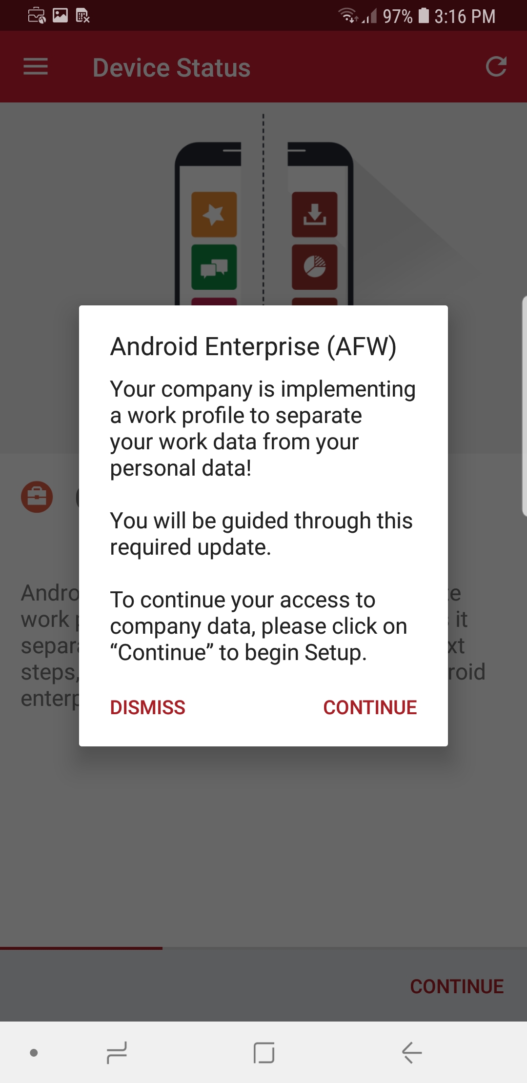
AFW notifies the user that it is creating the personal workspace. The next two screens repeat Steps 3 and 4 as above.
Figure 2‑177 AFW Workspace Creation
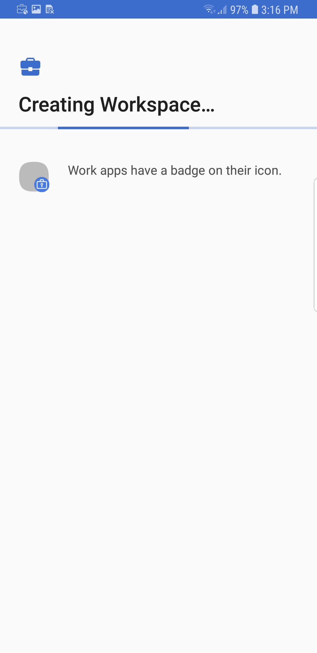
At the Device Status > Work Profile Lock Preferences screen, select Continue.
Figure 2‑178 MobileIron Work Profile Lock Preferences
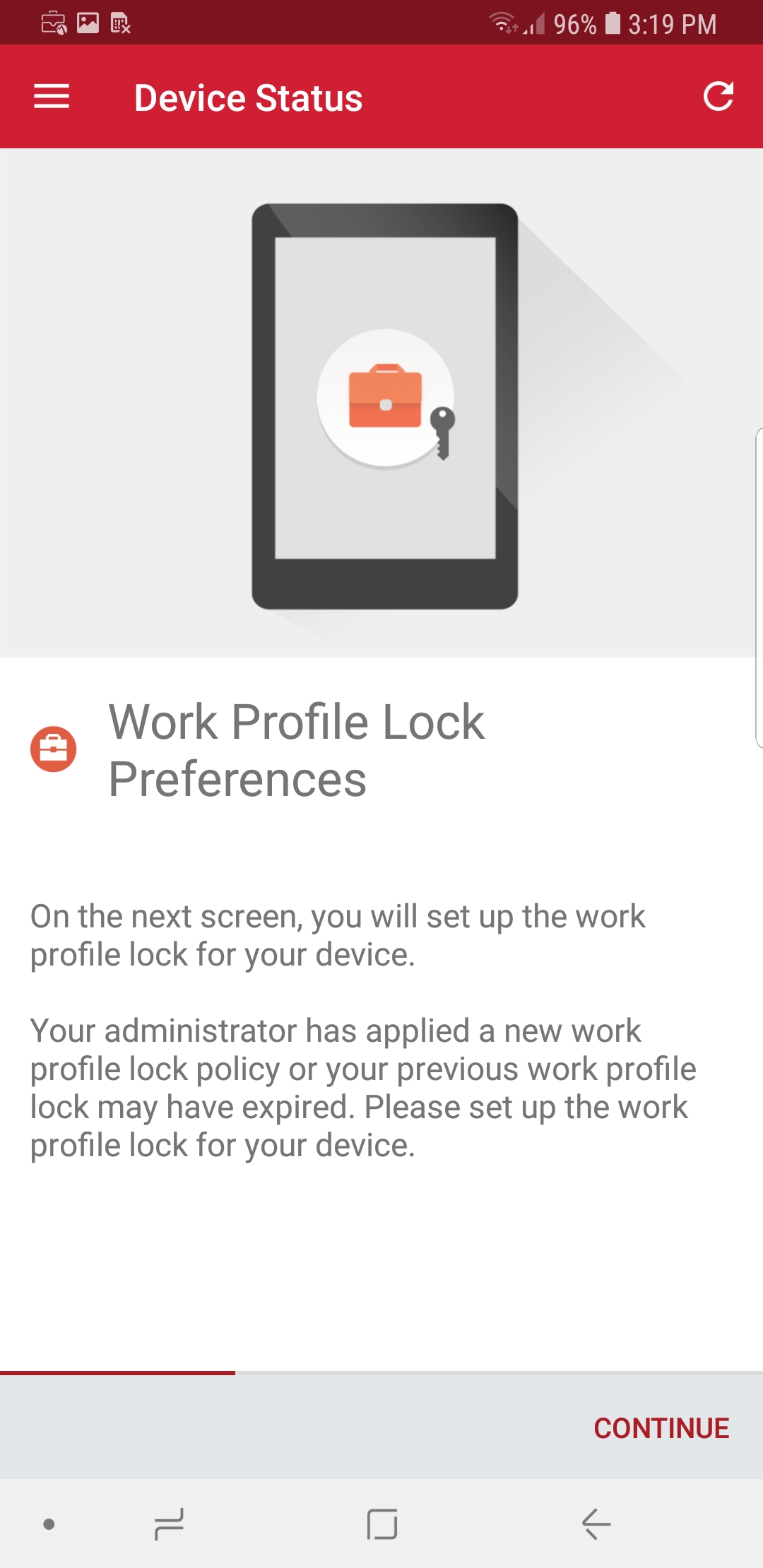
The user will be prompted to create a passcode to protect the AFW container.
At the Device Status > Add Google Account screen, select Continue.
Figure 2‑179 MobileIron Google Account Configuration
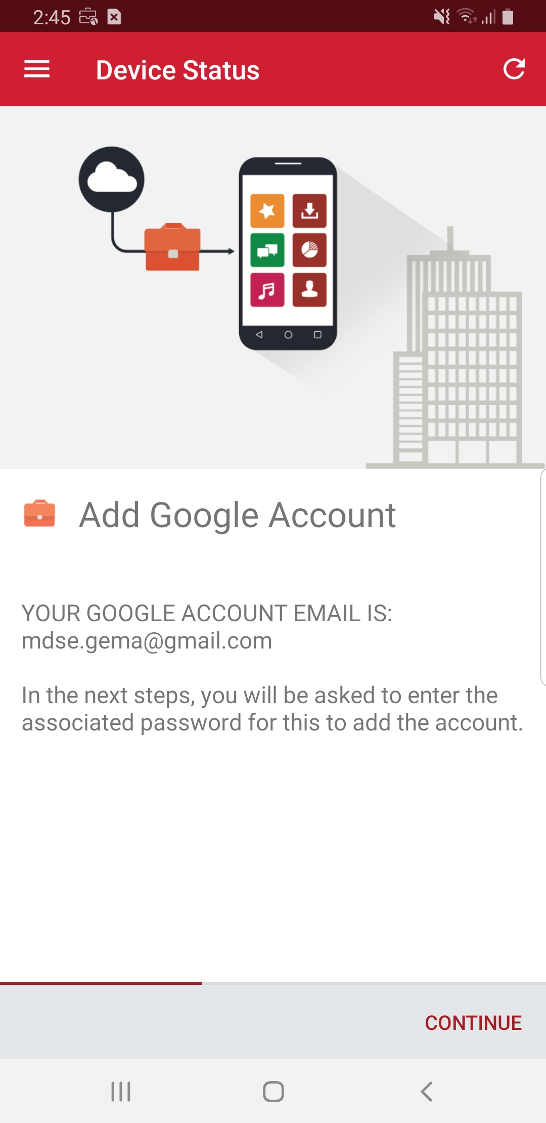
The user will be prompted to authenticate to the same Google domain account mapped to their MobileIron account based on the email address set in the AFW configuration in MobileIron Core. In our example implementation, the mapped Google account is mdse.gema@gmail.com.
Once the Mobile@Work app has been provisioned with the user’s account, the Device Status screen should appear; the device has now successfully been provisioned into MobileIron.
Figure 2‑180 MobileIron Device Status