NIST SPECIAL PUBLICATION 1800-2C
Identity and Access Management
for Electric Utilities
Volume C:
How-to Guides
Jim McCarthy
National Cybersecurity Center of Excellence
Information Technology Laboratory
Don Faatz
Harry Perper
Chris Peloquin
John Wiltberger
The MITRE Corporation
McLean, VA
Leah Kauffman, Editor-in-Chief
National Cybersecurity Center of Excellence
Information Technology Laboratory
July 2018
The first draft of this publication is available free of charge from: https://www.nccoe.nist.gov/sites/default/files/library/sp1800/es-idam-nist-sp1800-2-draft.pdf

DISCLAIMER
Certain commercial entities, equipment, products, or materials may be identified in this document in order to describe an experimental procedure or concept adequately. Such identification is not intended to imply recommendation or endorsement by NIST or NCCoE, nor is it intended to imply that the entities, equipment, products, or materials are necessarily the best available for the purpose.
National Institute of Standards and Technology Special Publication 1800-2C, Natl. Inst. Stand. Technol. Spec. Publ. 1800-2C, 389 pages, (July 2018), CODEN: NSPUE2
FEEDBACK
As a private-public partnership, we are always seeking feedback on our Practice Guides. We are particularly interested in seeing how businesses apply NCCoE reference designs in the real world. If you have implemented the reference design, or have questions about applying it in your environment, please email us at energy_nccoe@nist.gov.
National Cybersecurity Center of Excellence
National Institute of Standards and Technology
100 Bureau Drive
Mail Stop 2002
Gaithersburg, MD 20899
Email: nccoe@nist.gov
NATIONAL CYBERSECURITY CENTER OF EXCELLENCE
The National Cybersecurity Center of Excellence (NCCoE), a part of the National Institute of Standards and Technology (NIST), is a collaborative hub where industry organizations, government agencies, and academic institutions work together to address businesses’ most pressing cybersecurity issues. This public-private partnership enables the creation of practical cybersecurity solutions for specific industries, as well as for broad, cross-sector technology challenges. Through consortia under Cooperative Research and Development Agreements (CRADAs), including technology partners—from Fortune 50 market leaders to smaller companies specializing in IT security—the NCCoE applies standards and best practices to develop modular, easily adaptable example cybersecurity solutions using commercially available technology. The NCCoE documents these example solutions in the NIST Special Publication 1800 series, which maps capabilities to the NIST Cyber Security Framework and details the steps needed for another entity to recreate the example solution. The NCCoE was established in 2012 by NIST in partnership with the State of Maryland and Montgomery County, Md.
To learn more about the NCCoE, visit https://www.nccoe.nist.gov. To learn more about NIST, visit https://www.nist.gov.
NIST CYBERSECURITY PRACTICE GUIDES
NIST Cybersecurity Practice Guides (Special Publication Series 1800) target specific cybersecurity challenges in the public and private sectors. They are practical, user-friendly guides that facilitate the adoption of standards-based approaches to cybersecurity. They show members of the information security community how to implement example solutions that help them align more easily with relevant standards and best practices and provide users with the materials lists, configuration files, and other information they need to implement a similar approach.
The documents in this series describe example implementations of cybersecurity practices that businesses and other organizations may voluntarily adopt. These documents do not describe regulations or mandatory practices, nor do they carry statutory authority.
ABSTRACT
To protect power generation, transmission, and distribution, energy companies need to control physical and logical access to their resources, including buildings, equipment, information technology (IT), and operational technology (OT). They must authenticate, with a high degree of certainty, authorized individuals to the devices and facilities to which the companies are giving access rights. In addition, they need to enforce access-control policies (e.g., allow, deny, inquire further) consistently, uniformly, and quickly across all of their resources. This project resulted from direct dialog among NCCoE staff and members of the electricity subsector, mainly from electric power companies and those who provide equipment and/or services to them. The goal of this project is to demonstrate a converged, standards-based technical approach that unifies identity and access management (IdAM) functions across OT networks, physical access control systems (PACS), and IT systems. These networks often operate independently, which can result in identity and access information disparity, increased costs, inefficiencies, and a loss of capacity and service delivery capability. Also, these networks support different infrastructures, each with unique security risks. The converged IdAM solution must be constructed to effectively address the highest-risk infrastructure. This guide describes our collaborative efforts with technology providers and electric‑company stakeholders to address the security challenges that energy providers face in the core function of IdAM. This guide offers a technical approach to meeting the challenge and also incorporates a business‑value mindset by identifying the strategic considerations involved in implementing new technologies. This NIST Cybersecurity Practice Guide provides a modular, open, end-to-end example solution that can be tailored and implemented by energy providers of varying sizes and levels of IT sophistication. It shows energy providers how we met the challenge by using open‑source and commercially available tools and technologies that are consistent with cybersecurity standards. The use‑case scenario is based on a normal day-to-day business operational scenario that provides the underlying impetus for the functionality presented in this guide. While the reference solution was demonstrated with a certain suite of products, this guide does not endorse these specific products. Instead, this guide presents the characteristics and capabilities that an organization’s security experts can use to identify similar standards-based products that can be integrated quickly and cost-effectively with an energy provider’s existing tools and infrastructure.
KEYWORDS
cyber, physical, and operational security; cybersecurity; electricity subsector; energy sector; identity and access management; information technology
ACKNOWLEDGMENTS
We are grateful to the following individuals for their generous contributions of expertise and time.
| Name | Organization |
|---|---|
| Jasvir Gill | AlertEnterprise |
| Srini Kakkera | AlertEnterprise |
| Srinivas Adepu | AlertEnterprise |
| Pan Kamal | AlertEnterprise |
| Mike Dullea | CA Technologies |
| Ted Short | CA Technologies |
| Alan Zhu | CA Technologies |
| Peter Romness | Cisco Systems |
| Lila Kee | GlobalSign |
| Sid Desai | GlobalSign |
| Paul Townsend | Mount Airey Group (MAG) |
| Joe Lloyd | Mount Airey Group (MAG) |
| Paul Timmel | National Security Agency |
| Victoria Pillitteri | NIST |
| Jonathan Margulies | Qmulos |
| Ayal Vogel | RADiFlow |
| Dario Lobozzo | RADiFlow |
| Steve Schmalz | RSA |
| Tony Kroukamp (The SCE Group) | RSA |
| Kala Kinyon (The SCE Group) | RSA |
| Ulrich Schulz | RSA |
| Dave Barnard | RS2 Technologies |
| David Bensky | RS2 Technologies |
| Rich Gillespie (IACS Inc.) | RS2 Technologies |
| George Wrenn | Schneider Electric |
| Michael Pyle | Schneider Electric |
| Bill Johnson | TDi Technologies |
| Pam Johnson | TDi Technologies |
| Clyde Poole | TDi Technologies |
| Nadya Bartol | Utilities Telecom Council (UTC) |
| Danny Vitale | XTec |
The Technology Partners/Collaborators who participated in this build submitted their capabilities in response to a notice in the Federal Register. Respondents with relevant capabilities or product components were invited to sign a Cooperative Research and Development Agreement (CRADA) with NIST, allowing them to participate in a consortium to build this example solution. We worked with:
| Technology Partner/Collaborator | Build Involvement |
|---|---|
| AlertEnterprise | User access authorization provisioning |
| CA Technologies | IdAM workflow, provisions identities and authorizations to Active Directory instances |
| Cisco Systems | Network Access control |
| GlobalSign | Provides North American Energy Standards Board (NAESB)-compliant X.509 certificates |
| Mount Airey Group (MAG) | Manages attributes that control access to high-value transactions. |
| RADiFlow | Controls communication among industrial control system (ICS) devices |
| RSA | IdAM workflow, provisions identities and authorizations to Active Directory instances |
| RS2 Technologies | Controls physical access |
| Schneider Electric | Controls access to devices in the ICS / Supervisory Control and Data Acquisition (SCADA) network |
| TDi Technologies | Controls and logs access to ICS devices by people (ICS engineers and technicians) |
| XTec | Provides Personal Identity Verification Interoperable (PIV‑I) smart-card credentials and a physical-access-control capability using the smart card |
List of Figures
Figure 2‑1 Management and Production Networks
Figure 2‑2 IdAM Build Implementation Production Network
Figure 2‑4 Build #1 IdAM Network
Figure 2‑5 Build #2 IdAM Network
Figure 7‑2 IMG System Edit Window
Figure 7‑3 IMG Attributes Window
Figure 7‑5 IMG User Attributes Examples (1 of 3)
Figure 7‑6 IMG User Attributes Examples (2 of 3)
Figure 7‑7 IMG User Attributes Examples (3 of 3)
Figure 7‑8 IMG Edit Attributes
Figure 7‑9 IMG Account Attributes Example
Figure 7‑10 IMG Resources Directories
Figure 7‑11 IMG Create Directory
Figure 7‑12 IMG Create Directory
Figure 7‑13 IMG Directory Information
Figure 7‑14 IMG Create Directory
Figure 7‑17 IMG Create Identity Collector
Figure 7‑19 IMG HR Identities (cont.)
Figure 7‑20 IMG HR Identities – Users
Figure 7‑22 IMG HR Identities (Continued)
Figure 7‑23 IMG Adaptive Directory Container
Figure 7‑24 IMG Identity Collector
Figure 7‑25 IMG AD Identity Collector (1 of 5)
Figure 7‑26 IMG AD Identity Collector (2 of 5)
Figure 7‑27 IMG AD Identity Collector (3 of 5)
Figure 7‑28 IMG AD Identity Collector (4 of 5)
Figure 7‑29 IMG AD Identity Collector (5 of 5)
Figure 7‑30 IMG AD Create Account Collector
Figure 7‑31 IMG Edit Collector (1 of 10)
Figure 7‑32 IMG Edit Collector (2 of 10)
Figure 7‑33 IMG Edit Collector (3 of 10)
Figure 7‑34 IMG Edit Collector (4 of 10)
Figure 7‑35 IMG Edit Collector (5 of 10)
Figure 7‑36 IMG Edit Collector (6 of 10)
Figure 7‑37 IMG Edit Collector (7 of 10)
Figure 7‑38 IMG Edit Collector (8 of 10)
Figure 7‑39 IMG Edit Collector (9 of 10)
Figure 7‑40 IMG Edit Collector (10 of 10)
Figure 7‑42 IMG Successful Test Example
Figure 7‑43 IMG Unification Configuration
Figure 7‑44 IMG Participating Collectors
Figure 7‑45 IMG Edit Participating Collectors
Figure 7‑46 IMG Edit Participating Collectors (Continued)
Figure 7‑47 IMG Unification Configuration Attribute Sources
Figure 7‑48 IMG Edit User Attribute Mapping
Figure 7‑49 IMG Edit User Attribute Mapping (Continued)
Figure 7‑50 IMG Unification Configuration Joins
Figure 7‑52 IMG Start Data Collection
Figure 7‑54 IMG Data Collection Monitoring
Figure 7‑55 IMG Data Collection Review
Figure 7‑57 IMG Discover Roles
Figure 7‑58 IMG Discover Roles (1 of 3)
Figure 7‑59 IMG Discover Roles (2 of 3)
Figure 7‑60 IMG Discover Roles (3 of 3)
Figure 7‑61 IMG Discover Roles – Combining
Figure 7‑62 IMG Roles Definitions
Figure 7‑65 IMG User Termination
Figure 7‑66 IMG User Termination (Continued)
Figure 7‑67 IMG Request Configuration
Figure 7‑68 IMG Account Template
Figure 7‑69 IMG IT Account Template
Figure 7‑70 IMG AFX Connectors
Figure 7‑71 IMG AFX Connectors
Figure 7‑72 IMG Create Connector
Figure 7‑73 IMG AD Connector AFX Server: General
Figure 7‑74 IMG AD Connector AFX Server: Settings (1 of 3)
Figure 7‑75 IMG AD Connector AFX Server: Settings (2 of 3)
Figure 7‑76 IMG AD Connector AFX Server: Settings (3 of 3)
Figure 7‑77 IMG AD Connector AFX Server: Capabilities
Figure 7‑78 IMG AD Connector IT Capability Configuration (1 of 13)
Figure 7‑79 IMG AD Connector IT Capability Configuration (2 of 13)
Figure 7‑80 IMG AD Connector IT Capability Configuration (3 of 13)
Figure 7‑81 IMG AD Connector IT Capability Configuration (4 of 13)
Figure 7‑82 IMG AD Connector IT Capability Configuration (5 of 13)
Figure 7‑83 IMG AD Connector IT Capability Configuration (6 of 13)
Figure 7‑84 IMG AD Connector IT Capability Configuration (7 of 13)
Figure 7‑85 IMG AD Connector IT Capability Configuration (8 of 13)
Figure 7‑86 IMG AD Connector IT Capability Configuration (9 of 13)
Figure 7‑87 IMG AD Connector IT Capability Configuration (10 of 13)
Figure 7‑88 IMG AD Connector IT Capability Configuration (11 of 13)
Figure 7‑89 IMG AD Connector IT Capability Configuration (12 of 13)
Figure 7‑90 IMG AD Connector IT Capability Configuration (13 of 13)
Figure 7‑91 IMG Resources Directories
Figure 7‑93 IMG AD AFX Connector Binding
Figure 7‑94 IMG Resources Directories
Figure 7‑96 IMG Requests Activities
Figure 7‑97 IMG Accepted Access Request
Figure 7‑99 IMG New User Provisioned
Figure 7‑100 IMG Successful User Add
Figure 7‑101 IMG Requests Activities
Figure 7‑102 IMG Request Status
Figure 7‑103 IMG User Synchronization Menu Item
Figure 7‑104 IMG User Synchronization Status
Figure 8‑1 Adaptive Directory Login Page
Figure 8‑2 Adaptive Directory Main Page
Figure 8‑3 Adaptive Directory Tools Page
Figure 8‑4 Adaptive Directory Server Backend Settings
Figure 8‑5 Adaptive Directory LDAP Data Source
Figure 8‑6 Adaptive Directory Configuration of Naming Context
Figure 8‑7 Adaptive Directory New Naming Context
Figure 8‑8 Adaptive Directory Configure Virtual Tree
Figure 8‑9 Adaptive Directory Virtual Tree
Figure 8‑10 Adaptive Directory Create New Level
Figure 8‑11 Adaptive Directory New Level Name
Figure 8‑12 Adaptive Directory Backend Mapping
Figure 8‑13 Adaptive Directory Backend Mapping
Figure 8‑14 Adaptive Directory Configure LDAP Backend
Figure 8‑15 Adaptive Directory Addition Attributes
Figure 8‑16 Adaptive Directory Add/Edit Main Attribute
Figure 8‑17 Adaptive Directory Add Attribute
Figure 8‑18 Adaptive Directory Edit Collector
Figure 8‑19 Adaptive Directory Search Configuration for Accounts
Figure 9‑1 Adaptive Directory Search Configuration for Accounts
Figure 9‑2 Guardian ActiveMQ Home/Data Directory
Figure 9‑4 Guardian DB Connector Attributes
Figure 9‑5 Create DropDown Values
Figure 9‑7 Guardian Identify Configuraton
Figure 9‑8 Create Recon Authoritative Fields
Figure 9‑9 Guardian Recon Authoritative Fields
Figure 9‑10 Create External Provisioning Attribute
Figure 9‑12 Provisioning Mapping
Figure 9‑13 Guardian DB Connector Attribute Mapping
Figure 9‑16 Define Rule Conditions for Other Request Categories
Figure 9‑17 Suggest/Default Access
Figure 9‑21 Guardian User Policy
Figure 9‑23 Guardian Job Scheduler Triggers Field Map
Figure 9‑24 Guardian Reconciliation Job
Figure 9‑25 Guardian DB Connector Attributes
Figure 9‑26 Create DropDown Values
Figure 9‑28 Create DropDown Values
Figure 9‑30 Guardian Identity Configuration
Figure 9‑31 Create Recon Authoritative Fields
Figure 9‑32 Guardian Recon Authoritative Fields
Figure 9‑33 Create External Provisioning Attribute
Figure 9‑34 Configuring Fields
Figure 9‑35 Provisioning Mapping
Figure 9‑36 Guardian DB Connector Attribute Mapping
Figure 9‑39 Remove User Access and ChangeAccess
Figure 9‑42 New Policy Designer
Figure 9‑44 Guardian User Policy
Figure 9‑46 Guardian Job Scheduler Triggers Field Map
Figure 9‑47 Guardian Reconciliation Job
Figure 13‑1 Ozone Proof Settings
Figure 13‑2 Ozone Authority Web Service
Figure 13‑3 Ozone Authority Connection Information
Figure 13‑4 Ozone LDAP Publication Point
Figure 13‑5 Ozone Directory Connection Information
Figure 13‑6 Ozone Import Group from Directory
Figure 13‑7 Ozone New Proof Information
Figure 13‑8 Ozone New Proof Administrators
Figure 13‑10 Ozone Add Authorization Proof
Figure 13‑11 Ozone Server Configuration
Figure 13‑12 Ozone New Proof Information
Figure 13‑13 Ozone New Proof Authentication CRLs
Figure 13‑14 Ozone New Proof Authentication Source Configuration
Figure 13‑15 Ozone Envoy Configuration
Figure 15‑1 GlobalSign Overview
Figure 15‑2 GlobalSign Login Page
Figure 15‑3 GlobalSign Enterprise PKI Tab
Figure 15‑4 GlobalSign Order Licenses Page
Figure 15‑5 GlobalSign License Selection Page
Figure 15‑6 GlobalSign Product Details
Figure 15‑7 GlobalSign Payment Details
Figure 15‑8 GlobalSign Confirm Details
Figure 15‑9 GlobalSign Order Additional Profiles
Figure 15‑10. GlobalSign Certificate Profile Details
Figure 15‑11 GlobalSign Confirm Details
Figure 15‑12 GlobalSign View Admin Menu Options
Figure 15‑13 GlobalSign Oder Certificates
Figure 15‑14 GlobalSign Product Selection
Figure 15‑15 GlobalSign Certificate Identity Details
Figure 15‑16 GlobalSign Confirm Details
Figure 16‑1 Create New Project
Figure 16‑2 New Project Wizard
Figure 16‑3 Project Protection
Figure 16‑4 Administrator Password
Figure 16‑5 Project Explorer Window
Figure 16‑6 Tofino SA/MAC Address
Figure 16‑9 Project Explorer Assets Icon
Figure 16‑10 Project Explorer Tofino SA Icon
Figure 16‑12 Firewall Rule Wizard
Figure 16‑13 Asset Rule Profiles
Figure 16‑16 Save Rules in Project Explorer
Figure 16‑17 Apply Configuration Pane
Figure 16‑18 Loadable USB Drive Popup
List of Tables
Table 2‑1 Build Implementation Component List (Including Security Controls)
Table 2‑2 Build IP Address Assignments
Table 3‑1 Border Firewall Rules
Table 9‑2 Guardian PACS AD Parameters
Table 9‑3 Guardian Identity DB Parameters
Table 9‑4 Guardian ACCESSIT PACS DBConnector Parameters
Table 9‑5 New Custom Form Attributes
Table 9‑6 Create PacsHomeAccess Attribute
Table 9‑7 Create PacsWorkAccess Attribute
Table 9‑8 Create FacilityCode Attribute
Table 9‑9 Create PIN Attribute
Table 9‑12 Guardian Policy Engine Rule Action Handler
Table 9‑13 Manual Configuration Policy Engine Suggest/Default Access
Table 9‑14 Guardian User Policy
Table 9‑15 Guardian Job Scheduler Triggers
Table 9‑16 DB Connector Name and Label Fields
Table 9‑17 Guardian Manual Configuration System Parameters
Table 9‑18 Guardian Identity DB Parameters
Table 9‑19 Guardian PACS DBConnector Parameters
Table 9‑20 New Custom Form Attributes
Table 9‑21 Create PacsHomeAccess Attribute
Table 9‑22 Create PacsWorkAccess Attribute
Table 9‑23 Create FacilityCode Attribute
Table 9‑24 Create PIN Attribute
Table 9‑26 Guardian Manual Configuration Policy Engine Rules
Table 9‑27 Guardian Manual Configuration Policy Engine Rules
Table 9‑28 Guardian User Policy
Table 9‑29 Guardian AlertEnterprise DB Trigger
1. Introduction
The following guides show information technology (IT) professionals and security engineers how we implemented this example solution. We cover all of the products employed in this reference design. We do not recreate the product manufacturers’ documentation, which is presumed to be widely available. Rather, these guides show how we incorporated the products together in our environment.
Note: These are not comprehensive tutorials. There are many possible service and security configurations for these products that are out of scope for this reference design.
1.1. Practice Guide Structure
This National Institute of Standards and Technology (NIST) Cybersecurity Practice Guide demonstrates a standards-based example solution and provides users with the information they need to replicate this approach to identity and access management (IdAM). This reference design is modular and can be deployed in whole or in parts.
This guide contains three volumes:
- NIST Special Publication (SP) 1800-2A Executive Summary
- NIST SP 1800-2B: Approach, Architecture, and Security Characteristics – what we built and why
- NIST SP 1800-2C: How To Guides – instructions for building the example solution (you are here)
Depending on your role in your organization, you might use this guide in different ways:
Energy utility leaders, including chief security and technology officers will be interested in the Executive Summary (NIST SP 1800-2A), which describes the:
- challenges enterprises face in implementing and using IdAM systems
- example solution built at the NCCoE
- benefits of adopting the example solution
Technology or security program managers who are concerned with how to identify, understand, assess, and mitigate risk will be interested in this part of the guide, NIST SP 1800-2B, which describes what we did and why. The following sections will be of particular interest:
- Section 4.4.3 Risk, provides a description of the risk analysis we performed
- Section 4.4.4, Security Control Map, maps the security characteristics of this example solution to cybersecurity standards and best practices
You might share the Executive Summary, NIST SP 1800-2A, with your leadership team members to help them understand the importance of adopting standards-based identity and access management for electric utilities.
IT professionals who want to implement an approach like this will find the whole practice guide useful. You can use the How-To portion of the guide, NIST SP 1800-2C, to replicate all or parts of the build created in our lab. The How-To guide provides specific product installation, configuration, and integration instructions for implementing the example solution. We do not recreate the product manufacturers’ documentation, which is generally widely available. Rather, we show how we incorporated the products together in our environment to create an example solution.
This guide assumes that IT professionals have experience implementing security products within the enterprise. While we have used a suite of commercial products to address this challenge, this guide does not endorse these particular products. Your organization can adopt this solution or one that adheres to these guidelines in whole, or you can use this guide as a starting point for tailoring and implementing parts of IdAM for electric utilities. Your organization’s security experts should identify the products that will best integrate with your existing tools and IT system infrastructure. We hope you will seek products that are congruent with applicable standards and best practices. Section 4.5, Technologies, of NIST SP 1800-2B, lists the products we used and maps them to the cybersecurity controls provided by this reference solution.
The security characteristics in our access management platform are informed by guidance and best practices from standards organizations, including the North American Electric Reliability Corporation’s (NERC) Critical Infrastructure Protection (CIP) standards. In addition, this document was reviewed by the NERC Electricity Sector Information Sharing and Analysis Center (ES-ISAC) to ensure that the approach was informed by standards and NERC regulations.
1.2. Typographical Conventions
The following table presents typographic conventions used in this volume.
| Typeface/Symbol | Meaning | Example | |
|---|---|---|---|
| Italics | filenames and pathnames references to documents that are not hyperlinks, new terms, and placeholders |
For detailed definitions of terms, see the NCCoE Glossary. | |
| Bold | names of menus, options, command buttons and fields | Choose File > Edit. | |
Monospace
|
command-line input, on-screen computer output, sample code examples, status codes | mkdir
|
|
Monospace Bold
|
command-line user input contrasted with computer output | service sshd start
|
|
| blue text | link to other parts of the document, a web URL, or an email address | All publications from NIST’s National Cybersecurity Center of Excellence are available at https:/www.nccoe.nist.gov. | |
2. Build Overview
The National Cybersecurity Center of Excellence (NCCoE) constructed the IdAM build infrastructure by using commercial off-the-shelf hardware and software. The infrastructure was built on Dell model PowerEdge R620 server hardware. The server operating system (OS) was the VMware vSphere virtualization operating environment. The use of virtualization is an artifact of the NCCoE laboratory environment. It allows the NCCoE build to represent a typical utility environment in the laboratory. The solution can be built on dedicated hardware. In addition, a 6-terabyte Dell EqualLogic network attached storage (NAS) product was used for storage. Dell model PowerConnect 7024 and Cisco Catalyst 3650 and 3550 physical switches were used to interconnect the server hardware, external network components, and the NAS.
The lab network was accessible from the public internet via a virtual private network (VPN) appliance and firewall to enable secure internet and remote access. The lab network was not connected to the NIST enterprise network. Table 2‑1 lists which software and hardware components were used in the builds, the specific function that each component contributes, and whether the product was installed within the virtual environment or as physical device.
Table 2‑1 Build Implementation Component List (Including Security Controls)
| Product Vendor | Component | Function | Implementation (physical device or virtual environment) |
|---|---|---|---|
| Dell | PowerEdge R620 | Physical server hardware | Physical device |
| Dell | PowerConnect 7024 | Physical network switch | Physical device |
| Dell | EqualLogic | NAS | Physical device |
| VMware | vSphere vCenter Server Version 5.5 | Virtual server and workstation environment | Virtual environment |
| Microsoft | Windows Server 2012 r2 Active Directory (AD) Server | Authentication and authority | Virtual environment |
| Microsoft | Windows 7 | Information management | Virtual environment |
| Microsoft | Windows Server 2012 r2 Domain Name System (DNS) Server | DNS | Virtual environment |
| Microsoft | Structured Query Language (SQL) Server | Database | Virtual environment |
| AlertEnterprise | Enterprise Guardian | Interface and translation between the IdAM central store and the physical access control system (PACS) management server | Virtual environment |
| CA Technologies (CA) | Identity Manager Release 12.6.05 Build 06109.28 | Identity and access automation management application, IdAM provisioning | Virtual environment |
| Cisco | Identity Services Engine (ISE) Network Server 3415 | Network access controller | Virtual environment |
| Cisco | Catalyst 3550 | Network switch | Physical device |
| Cisco | Catalyst 3650 | TrustSec-enabled physical network switch | Physical device |
| GlobalSign | Secure Socket Layer (SSL) Certificate | Cloud certificate and registration authority | Virtual environment |
| Mount Airey Group (MAG) | Ozone Authority | Central attribute management system | Virtual environment |
| MAG | Ozone Console | Ozone administrative management console | Virtual environment |
| MAG | Ozone Envoy | Enterprise identity store interface | Virtual environment |
| MAG | Ozone Server | Ozone centralized attribute‑based authorization server | Virtual environment |
| RADiFlow | iSIM – Industrial Service Management Tool | Supervisory control and data acquisition (SCADA) router management application | Physical device |
| RADiFlow | SCADA Router RF-3180S | Router/firewall for SCADA network | Physical device |
| RSA | Adaptive Directory Version 7.1.5 | Central identity store, IdAM provisioning | Virtual environment |
| RSA | Identity Management and Governance (IMG) Version 6.9 Build 74968 | Central IdAM system (workflow management) | Virtual environment |
| TDi Technologies | ConsoleWorks | Privileged user access controller, monitor, and logging system | Virtual environment |
| RS2 Technologies (RS2) | Access It! Universal Release 4.1.15 Physical-access-control components |
Configures and monitors the PACS devices (e.g., card readers, keypads) | Virtual-environment server, and physical-device card reader |
| Schweitzer Electronics Laboratory (SEL) | SEL-2411 | Remote Terminal Unit (RTU) | Physical device |
| Schneider Electric | Tofino Firewall model number TCSEFEA23F3F20 | Ethernet / Internet Protocol (IP) firewall | Physical device |
| XTec | XNode | Remote access control and management | Physical device |
2.1. Build Implementation Overview
The build implementation consists of multiple networks implemented to mirror the infrastructure of a typical energy industry corporation. The networks include a management network and a production network (Figure 2‑1). The management network was implemented to facilitate the implementation, configuration, and management of the underlying infrastructure, including the physical servers, vSphere infrastructure, and monitoring. The production network (Figure 2‑2) consists of the following components:
- the demilitarized zone (DMZ): The DMZ presented in this practice guide is designed to support the NCCoE laboratory environment. Organizations should construct DMZs by using appropriate guidance for their environment, such as North American Electric Reliability Corporation (NERC) Guidance for Secure Interactive Remote Access.
- IdAM network
- IT network – business management system
- operational technology (OT) network – ICS/SCADA and energy management system (EMS)
- PACS network
These networks were implemented separately to represent a typical electric utility enterprise infrastructure. Firewalls are configured to route traffic and limit access among the production networks to block all traffic, except required internetwork communications. The primary internetwork communications are the user access and authorization updates from the central IdAM systems to and from the directories and the PACS, IT, and OT networks. The DMZ provides a protected neutral network space that the other networks of the production network can use to route traffic to and from the internet or each other.
Figure 2‑1 Management and Production Networks
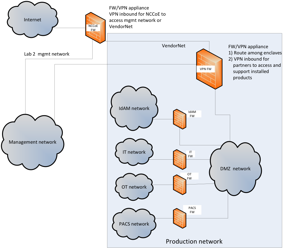
Figure 2‑2 IdAM Build Implementation Production Network
The IdAM network shown in Figure 2‑2 represents the proposed converged IdAM network/system. This network was separated to highlight the unique IdAM components proposed to address the use‑case requirements.
The IT network represents the business management network that typically supports corporate email, file sharing, printing, and internet access for general business-purpose computing and communications.
The OT network represents the network that is used to support the EMSs and ICS/SCADA systems. Typically, this network either is not connected to the enterprise IT network or is connected with a data diode (a one-way communication device from the OT network to the IT network). Two-way traffic is allowed, per NERC Critical Infrastructure Protection (CIP), and is enabled via the OT firewall, only for specific ports and protocols between specific systems identified by IP address.
The PACS network represents the network that is used to support the PACS across the enterprise. In our architecture, a firewall is configured to allow limited access to and from the PACS network to facilitate the communication of access and authorization information. Technically, this communication consists of user role and responsibility directory updates originating in the IdAM system.
The public internet is accessible by the lab environment to facilitate both cloud services and access for vendors and NCCoE administrators.
The VPN firewall was the access‑control point for vendors, to support the installation and configuration of their components of the architecture. The NCCoE also used this access to facilitate product training. This firewall also blocked unauthorized traffic from the public internet to the production networks. Additional firewalls are used to secure the multiple domain networks (IT, OT, IdAM, and PACS).
Switching in the implementation is executed using a series of physical and hypervisor soft switches. The use of virtualization is an artifact of the NCCoE laboratory environment. It allows the NCCoE build to represent a typical utility environment in the laboratory. Virtual local area network (VLAN) switching functions are handled by physical Dell switches and the virtual environment. Routing was accomplished using the firewalls.
2.2. Build Implementation Descriptions
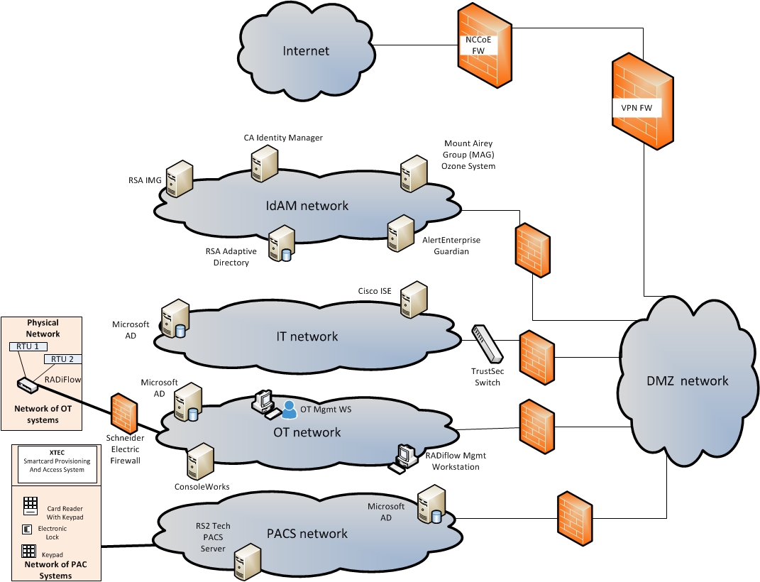
Figure 2‑3 depicts the build network comprising the management, VendorNet, IdAM, DMZ, IT, OT, and PACS subnetworks. VendorNet provides remote access for vendors to access, configure, demonstrate, and provide training for each of the implemented products. The IdAM network contains the central IdAM components of the build. The IT, OT, and PACS networks contain the representative components of a typical electric utility enterprise.
Figure 2‑3 Build Network

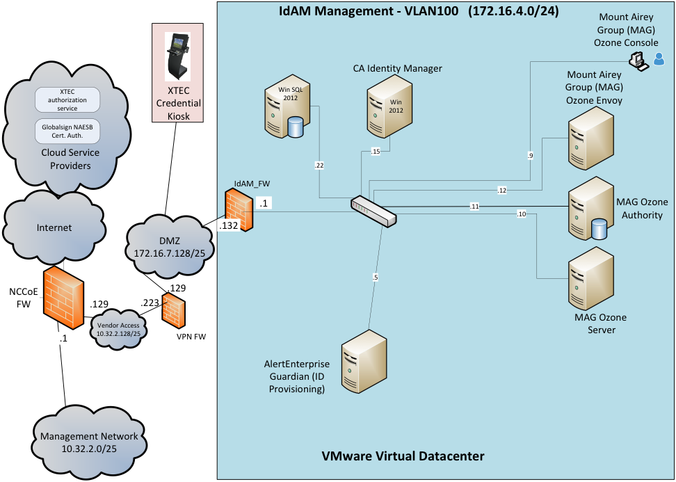
The IdAM network (Figure 2‑4 and Figure 2‑5) contains the central IdAM components for Build #1 and Build #2. The IdAM components are placed into a separate network to highlight the importance of protecting these assets and to simplify the demonstration of their capabilities.
Figure 2‑4 Build #1 IdAM Network
Build #1 uses the CA Identity Manager product for the IdAM system and identity store.
Figure 2‑5 Build #2 IdAM Network

Build #2 uses the RSA IMG and Adaptive Directory products for the IdAM system and identity store.
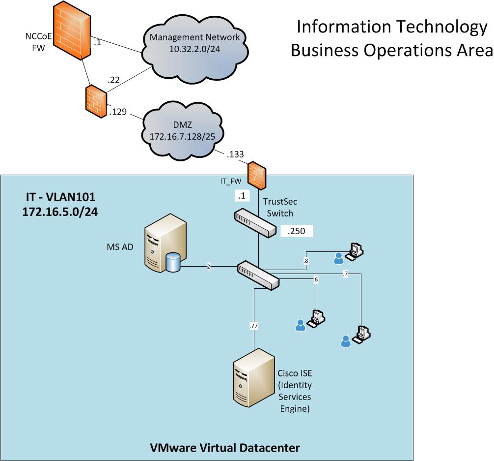
The IT network (Figure 2‑6) contains the components that are common in the business operations IT networks/systems in all organizations.
Figure 2‑6 IT Network
The OT network (Figure 2‑7) contains the OT components, which include representative components found in electric utility OT networks/systems. These components were chosen to demonstrate the integration capabilities of the central IdAM capability. The lab did not attempt to replicate a fully operational OT network or set of systems. Because we had a limited number of RTUs available, we used Raspberry Pi on the network to emulate an RTU.
Figure 2‑7 OT Network
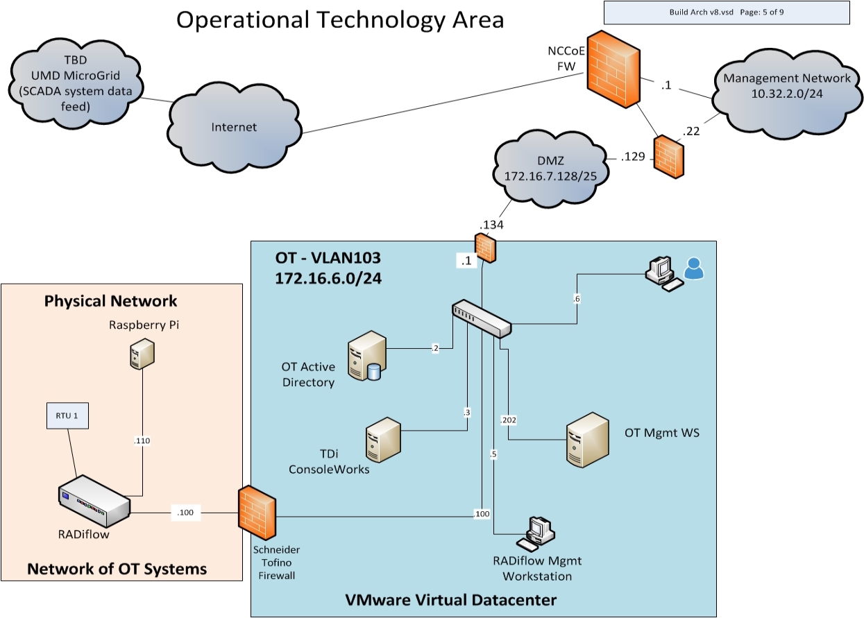
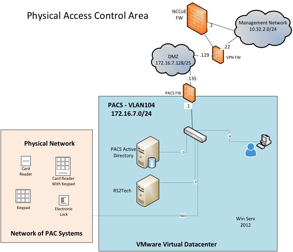
The PACS network (Figure 2‑8) contains the PACS components, which include representative components found in electric utility PACS. These components were chosen to demonstrate the integration capabilities of the central IdAM capability.
Figure 2‑8 PACS Network
2.3. IP Network Address Assignments
Table 2‑2 includes the IP address assignments used for the builds.
Table 2‑2 Build IP Address Assignments
| DMZ Network IP | System | Vendor Access Network | System | IdAM Management Network IP | System |
|---|---|---|---|---|---|
| 10.32.2.0/25 | Subnet | 10.32.2.128/25 | Subnet | 172.16.4.0/24 | Subnet |
| 10.32.2.1 | NCCoE Firewall (FW) /Gateway | 10.32.2.129 | NCCoE FW/Gateway | 172.16.4.1 | IdAM FW local area network (LAN) |
| 10.32.2.10 | Vcenter | 10.32.2.130 | Vendor AD | 172.16.4.2 | RSA IMG |
| 10.32.2.11 | ESXi #1 | 10.32.2.131 | Vendor Reliable Datagram Sockets (RDS) | 172.16.4.3 | RSA Adaptive Directory |
| 10.32.2.12 | ESXi #2 | 10.32.2.132 | RSA/SCE | 172.16.4.5 | AlertEnterprise |
| 10.32.2.22 | Border FW Wide Area Network (WAN) | 10.32.2.133 | AlertEnterprise | 172.16.4.9 | Ozone Console |
| 10.32.2.50 | RS1 file transfer protocol (FTP) Synology | 10.32.2.134 | CA | 172.16.4.10 | Ozone Server |
| 10.32.2.X | Veam Backup Server | 10.32.2.135 | RADiFlow | 172.16.4.11 | Ozone Authority |
| 10.32.2.136 | MAG | 172.16.4.12 | Ozone Envoy | ||
| 10.32.2.137 | TDi | 172.16.4.13 | Ozone Personal Profile Application (PPA) | ||
| 10.32.2.232 | Border FW OPT1 | 172.16.4.15 | CA Identity Manager | ||
| 172.16.4.22 | Microsoft SQL | ||||
| 172.16.4.253 | CentOS DNS | ||||
| IT Network IP | System | PAC Network IP | System | OT Network IP | System |
| 172.16.5.0/24 | Subnet | 172.16.7.0/25 | Subnet | 172.16.6.0/25 | Subnet |
| 172.16.5.1 | IT FW LAN | 172.16.7.1 | PACS FW LAN | 172.16.6.1 | OT FW LAN |
| 172.16.5.2 | IT AD, DNS, CA | 172.16.7.2 | PACS AD, DNS, CA | 172.16.6.2 | OT AD, DNS, CA |
| 172.16.5.6 | Workstation | 172.16.7.5 | N/A | 172.16.6.4 | RADiFlow FW/ Switch (SW) |
| 172.16.5.7 | Workstation | 172.16.7.6 | XTec XNode | 172.16.6.5 | Schneider Firewall |
| 172.16.7.11 | PACS Console | 172.16.6.6 | Workstation | ||
| 172.16.7.15 | PACS Workstation | 172.16.6.8 | TDi ConsoleWorks | ||
| 172.16.7.101 | Laboratory Door Controller | 172.16.6.100 | RADiFlow Terminal Server for SEL | ||
| 172.16.6.202 | RADiFlow Vendor Host |
3. Build Infrastructure
3.1. Operating Systems
All machines that were used in the build had one of the following OSs installed:
- Windows 7 enterprise
- Windows server 2008 R2
- Windows server 2012 R2
- MicroFocus SUSE Linux Enterprise Server 11
- CentOS 7
3.1.1. Windows Installation and Hardening Details
The NCCoE Windows OS images are derived from the Department of Defense (DoD) Security Technical Implementation Guide (STIG) images. The Windows systems were installed using installation files provided by the Defense Information Systems Agency (DISA). These images were chosen because they are standardized, hardened, and fully documented.1FThe STIG guidelines are available online at http://iase.disa.mil/stigs/os/Pages/index.aspx. The NCCoE chose this baseline configuration. Adopters of the NCCoE solution can use other accepted security baseline configurations, such as the Center for Internet Security (CIS) Security Benchmarks (https://www.cisecurity.org/cis-benchmarks/).
Modifications to the STIG‑compliant OS configurations were required for each product to enable its operation. The compliance results in Section 17 identify the specific OS configuration modifications (noncompliant configuration items) needed in each case.
3.1.2. SUSE Linux Enterprise Server 11 Installation and Hardening Details
The SUSE OS was included as part of the virtual appliance image provided by RSA for the IMG product. The center did not make any OS configuration changes. The OS was not configured to meet the DoD CentOS 6 STIG. The OS configurations for the SUSE Linux implementation are listed in Section 17. The compliance results report for SUSE Linux is included for illustration purposes (Section 17.2).
3.1.3. Base Linux Installation and Hardening Details
CentOS 7 was the NCCoE base Linux OS that was used in the build. This OS is available as an open‑source image. The OS was configured to meet the DoD CentOS 6 STIG, as no CentOS 7 STIG was available at the time when the build was implemented. The OS configurations for each Linux implementation are listed in Section 17. The compliance results reports identify the configuration items that do not conform to the STIG configuration guide.
3.2. Firewall Configurations
The firewalls were deployed to minimize the allowed traffic among the silo networks, as well as to minimize the traffic received from the DMZ and the public internet. The goal was to limit the cross-network traffic/connections to only those required to support the use case.
The following firewall configurations include the rules that were implemented in each of the firewalls for the build implementation (Table 3‑1 through Table 3-5). These configurations are provided to enable the reader to reproduce the traffic filtering/blocking that was achieved in the build implementation.
Table 3‑1 Border Firewall Rules
| Aliases | ||
|---|---|---|
| Name | Values | Description |
| VirtualInfra | 10.32.2.10-12 | Virtualization Systems for Build |
| VPNserver | 172.16.7.253 | VPN Server |
| WAN Interface | ||||||
|---|---|---|---|---|---|---|
| Allow/Deny | Protocol | Source | Port | Destination | Port | Description |
| Allow | IPv4 – All | 10.32.2.0/25 | Any | Any | Any | Allow all management network traffic |
| Allow | IPv4 – All | 10.255.2.0/25 | Any | Any | Any | Center VPN to all systems |
| Allow | IPv4 – Transmission Control Protocol (TCP) | Any | Any | WAN address | 80 | Allow access to WebGUI pfSense |
| Allow | IPv4 – TCP | 10.255.2.0/25 | Any | 172.16.4.8 | 5176 | Center VPN to ConsoleWorks |
| Allow | IPv4 – TCP | 10.255.2.0/25 | Any | 172.16.4.8 | 443 | Center VPN to ConsoleWorks Hypertext Transfer Protocol Secure (HTTPS) |
| Deny | IPv4 – TCP | Any | Any | WAN address | Any | Block all access to pfSense |
| Allow | IPv4 – TCP | Any | Any | 172.16.7.110 | 3389 | Remote Desktopo Protocol (RDP) to Lab-PC on PACS (backups) |
| LAN Interface | ||||||
|---|---|---|---|---|---|---|
| Allow/Deny | Protocol | Source | Port | Destination | Port | Description |
| Allow | IPv4 – All | 172.16.7.135 | Any | VirtualInfra | Any | Lab laptop to virtualization |
| Deny | IPv4 – All | Any | Any | VirtualInfra | Any | Block all to virtualization |
| Deny | IPv4 – TCP | 172.16.8.0/24 | Any | 10.32.2.0/25 | Any | Block vendor VPN from management |
| Deny | IPv4 – TCP | 10.32.2.128/25 | Any | 10.32.2.0/25 | Any | Block vendor VPN from management |
| Allow | IPv4 – All | LAN Net | Any | Any | Any | Default allow any LAN |
| Allow | IPv6 – All | LAN Net | Any | Any | Any | Default allow any LAN |
| Allow | IPv4 – TCP | 172.16.7.128/25 | Any | 10.32.2.117 | 3389 | RDP to 117 |
| Allow | IPv4 – User Datagram Protocol (UDP) | 172.16.7.128/25 | Any | 10.32.2.117 | 3389 | RDP to 117 |
| Deny | IPv4 – All | Any | Any | Any | Any | Block IPv4 |
| Deny | IPv6 – All | Any | Any | Any | Any | Block IPv6 |
Table 3‑2 IdAM Firewall Rules
| Aliases | ||
|---|---|---|
| Name | Values | Description |
| AD_DCs_All | 172.16.{5,6,7},2 | All Domain Controllers (DCs) in infrastructure |
| LinuxSystems | 172.16.4.{2,3,8,10, 11,12,253} | Used for Secure Socket Shell (SSH) |
| MAG_Linux | 172.16.4.{10,11,12} | Systems for MAG |
| WAN Interface | ||||||
|---|---|---|---|---|---|---|
| Allow/Deny | Protocol | Source | Port | Destination | Port | Description |
| Allow | IPv4 – All | 10.32.2.0/25 | Any | Any | Any | Allow all management network traffic |
| Allow | IPv4 – All | 10.255.2.0/25 | Any | Any | Any | Center VPN to all systems |
| Allow | IPv4 – TCP | 172.16.7.133 | Any | Any | Any | IT to IdAM |
| Allow | IPv4 – TCP | Any | Any | LinuxSystems | IMG | Allow SSH to Linux |
| Allow | IPv4 – All | Any | Any | 172.16.4.8 | 161, 162, 514, 5176 | Allow Simple Network Management Protocol (SNMP), Syslog, default to TDi |
| Allow | IPv4 – All | AD_DCs_All | Any | 172.16.4.15 | Any | AD DCs to IdAM-CA |
| Allow | IPv4 – All | 172.16.8.50 | Any | 172.16.4.15,22 | Any | CA to CA_srv12, CA_SQL_srv12 |
| Allow | IPv4 – TCP | Any | Any | 172.16.4.2 | 5900 to 5910 | Virtual Network Computing (VNC) to IMG |
| Allow | IPv4 – TCP | 172.16.7.2 | Any | 172.16.4.2 | Any | PACS AD to IMG |
| Allow | IPv4 – TCP | 172.16.7.2 | Any | 172.16.4.3 | Any | PACS AD to Adaptive Directory |
| Allow | IPv4 – TCP | 10.32.2.0/25 | Any | 172.16.4.8 | 517, 6443 | Management to TDi ConsoleWorks |
| LAN Interface | ||||||
|---|---|---|---|---|---|---|
| Allow/Deny | Protocol | Source | Port | Destination | Port | Description |
| Allow | IPv4 – All | LAN Net | Any | Any | Any | Default allow any LAN |
| Allow | IPv6 – All | LAN Net | Any | Any | Any | Default allow any LAN |
Table 3‑3 IT Firewall Rules
| Aliases | ||
|---|---|---|
| Name | Values | Description |
| Alert_Enterprise | 172.16.4.5 | AlertEnterprise |
| CA | 172.16.4.15 | CA |
| CA_RSA_Alert | 172.16.4.{2,3,5,15}, 172.16.7.132 | CA, RSA, Alert |
| ConsoleWorks | 172.15.4.8 | ConsoleWorks |
| IT_Network | 172.16.7.132 | IT network |
| LinuxSystems | 172.16.5.4 | All Linux on IT |
| Ozone | 172.16.4.10-12 | Ozone products |
| RSA | 172.16.4.2-3 | IMG, Adaptive Directory |
| WAN Interface | ||||||
|---|---|---|---|---|---|---|
| Allow/Deny | Protocol | Source | Port | Destination | Port | Description |
| Allow | IPv4 – All | 10.32.2.0/25 | Any | Any | Any | Allow all management network traffic |
| Allow | IPv4 – TCP | 172.16.7.132 | Any | Any | Any | IdAM to IT |
| Allow | IPv4 – TCP | Any | Any | LinuxSystems | 22 | Allow SSH to Linux |
| Allow | IPv4 – All | Any | Any | 172.16.5.2 | 53 | Allow DNS |
| Allow | IPv4 – TCP | IT_Network | Any | 172.16.5.4 | 25443 | Alert to ITEMAIL |
| Allow | IPv4 – TCP | ConsoleWorks | Any | LAN Net | 22,161 to 162 | TDi to IT-Net |
| Allow | IPv4 – TCP | CA_RSA_Alert | Any | 172.16.5.2 | 389, 636 | Lightweight Directory Access Protocol (LDAP) / Lightweight Directory Access Protocol over SSL (LDAPS) to AD |
| LAN Interface | ||||||
|---|---|---|---|---|---|---|
| Allow/Deny | Protocol | Source | Port | Destination | Port | Description |
| Allow | IPv4 – All | LAN Net | Any | Any | Any | Default allow any LAN |
| Allow | IPv6 – All | LAN Net | Any | Any | Any | Default allow any LAN |
Table 3‑4 OT Firewall Rules
| Aliases | ||
|---|---|---|
| Name | Values | Description |
| LinuxSystems | 172.16.6.7 | All Linux on OT |
| RADiFlow | 172.16.6.{4,6,202} | All RADiFlow IPs |
| WAN Interface | ||||||
|---|---|---|---|---|---|---|
| Allow/Deny | Protocol | Source | Port | Destination | Port | Description |
| Allow | IPv4 – All | 10.32.2.0/25 | Any | Any | Any | Allow all management network traffic |
| Allow | IPv4 – TCP | Any | Any | 172.16.6.10 | 22 | SSH to Raspberry Pi RTU |
| Allow | IPv4 – TCP | Any | Any | LinuxSystems | 22 | Allow SSH to Linux |
| Allow | IPv4 – All | Any | Any | 172.16.6.2 | 53 | Allow DNS |
| Allow | IPv4 – All | 172.16.4.8 | Any | LAN Net | 22, 161 to 162 | TDi to OT-Net |
| Allow | IPv4 – TCP | Any | Any | 172.16.6.2 | 389, 636 | Any LDAP to AD |
| Allow | IPv4 – TCP | 172.16.4.{2,3,15} | Any | 172.16.6.2 | Any | Adaptive Directory, IMG, CA Identity Manager to AD |
| Allow | IPv4 – TCP | Any | Any | 172.16.6.100 | 2001 to 2101 | Telnet access through RADiFlow |
| LAN Interface | ||||||
|---|---|---|---|---|---|---|
| Allow/Deny | Protocol | Source | Port | Destination | Port | Description |
| Allow | IPv4 – All | LAN Net | Any | Any | Any | Default allow any LAN |
| Allow | IPv6 – All | LAN Net | Any | Any | Any | Default allow any LAN |
Table 3‑5 PACS Firewall Rules
| Aliases | ||
|---|---|---|
| Name | Values | Description |
| VirtualInfra | 10.32.2.10-12 | Virtualization Systems for Build |
| WAN Interface | ||||||
|---|---|---|---|---|---|---|
| Allow/Deny | Protocol | Source | Port | Destination | Port | Description |
| Allow | IPv4 – All | 10.32.2.0/25 | Any | Any | Any | Allow all management network traffic |
| Allow | IPv4 – All | 172.16.7.132 | Any | 172.16.7.{2,11} | Any | IdAM to PACS-Console, PACS DC |
| Allow | IPv4 – TCP | Any | Any | 172.16.7.2 | 389, 636 | Any LDAP to AD |
| Allow | IPv4 – All | Any | Any | 172.16.7.2 | 53 | Allow DNS |
| Allow | IPv4 – All | 172.16.4.8 | Any | LAN Net | 22,161 to 162 | TDi to PACS-Net |
| Allow | IPv4 – TCP | 172.16.4.{2,3,15} | Any | 172.16.7.2 | Any | Adaptive Directory, IMG, CA Identity Manager to AD |
| Allow | IPv4 – TCP | Any | Any | 172.16.7.110 | 3389 | Microsoft Remote Desktop Protocol (MRDP) Network Address Translation to Laboratory Machine PACS |
| LAN Interface | ||||||
|---|---|---|---|---|---|---|
| Allow/Deny | Protocol | Source | Port | Destination | Port | Description |
| Allow | IPv4 – All | LAN Net | Any | Any | Any | Default allow any LAN |
| Allow | IPv6 – All | LAN Net | Any | Any | Any | Default allow any LAN |
3.3. Network Services
Microsoft AD was used to provide directory services in each silo network (OT, PACS, and IT). Linux CentOS 7 was used to provide DNS services in the IdAM network. Microsoft Windows Server was used to provide certificate authority services in each network.
3.3.1. IT Network – Network Services (AD and Certificate Authority) Installation and Configuration Settings
3.3.1.1. AD
Use these basic domain controller configuration settings:
- Hostname:
ITDC - Domain:
ES-IDAM-B1.TEST - IP:
172.16.5.2
Step-by-step instructions:
Launch Server Manager.
From the dashboard, select Option 2, Add Roles and Features.
Select Role-based or Feature-based installation.
From the server pool, select the local server named ITDC.
Select Active Directory Domain Service and DNS Server.
When prompted to add features, select Add Features for each role.
Wait for Server Manager to finish installing.
Select Post-Deployment Configuration for Active Directory from the Task menu.
Perform the following actions after Active Directory Domain Services Configuration wizard automatically launches:
Select Add a New Forest deployment operation.
Specify
ES-IDAM-B1.TESTroot domain, and then select Next.Select Windows Server 2012 R2 for both the Forest Functional Level and the Domain Functional Level.
Perform the following actions under Domain Controller Capabilities:
- Check both DNS server and Global Catalog.
- Uncheck read-only domain controller.
- Specify a password for Directory Services Restore Mode (DSRM), and then select Next.
Continue through the wizard without modifying any options.
Select Install on the next window. After installation, the server automatically reboots.
3.3.1.2. Certificate Authority Role
Use these basic certificate authority configuration settings:
- Certificate authority setup type:
Enterprise CA - Certificate authority type:
Root CA - Cryptographic options:
RSA 2048andSHA1 - CN:
IT-ES-IDAM-B1-IDAM-ITDC - DN suffix:
DC=IT-ES-IDAM-B1, DC=TEST
Step-by-step instructions:
- From the Server Manager dashboard, select Option 2, Add Roles and Features.
- Select Role-based or Feature-based installation (this is a single option to choose).
- From the server pool, select the local server named OTDC.
- Select Active Directory Certificate Services.
- When prompted to add features, select Add Features.
- When prompted to select roles services, check Certificate Authority.
- After the Server Manager finishes installing, select Post-deployment Configuration for Certificate Services from the Task menu.
- When prompted to specify the certificate authority setup type, select Enterprise CA.
- When prompted to specify the certificate authority type, select Root CA.
- When prompted to specify a private key, select Create a new private key.
- When prompted to specify cryptographic options, select RSA with a key length of 2048, and select SHA1 for the hash algorithm.
- Leave the CN and DN suffix, which should be based on the computer’s hostname and domain.
- Select 5 years for the certificate validity period.
- Leave the default options for the certificate database and log location.
- After the configuration is complete, restart the server.
3.3.2. OT Network – Network Services (AD, DNS Server, and Certificate Authority) Installation and Configuration Settings
3.3.2.1. AD Domain Services and DNS Server
Use these basic certificate authority configuration settings:
- Hostname:
OTDC - Domain:
OT-ES-IDAM-B1.TEST - IP:
172.16.6.2
Step-by-step instructions:
Launch Server Manager.
From the dashboard, select Option 2, Add Roles and Features.
Select Role-based or Feature-based installation.
From the server pool, select the local server named OTDC.
Select Active Directory Domain Service and DNS Server.
When prompted to add features, select Add Features for each role.
After the Server Manager finishes installing, select Post-deployment Configuration for Active Directory from the Task menu.
The Active Directory Domain Services Configuration wizard launches:
For the deployment operation, select Add a New Forest.
For the root domain, specify
OT-ES-IDAM-B1.TEST, and then select Next.For both the Forest Functional Level and the Domain Functional Level, select Windows Server 2012 R2.
Under Domain Controller Capabilities:
- Check both DNS server and Global Catalog.
- Uncheck read-only domain controller.
- Specify a password for DSRM, and then select Next.
Continue through the wizard without modifying any options.
On the last page, select Install. After installation, the server automatically reboots.
3.3.2.2. Certificate Authority Role
Use these basic certificate authority configuration settings:
- Certificate authority setup type:
Enterprise CA - Certificate authority type:
Root CA - Cryptographic options:
RSA 2048 and SHA1 - CN:
OT-ES-IDAM-B1-IDAM-OTDC - DN suffix:
DC=OT-ES-IDAM-B1, DC=TEST
Step-by-step instructions:
- Ensure that the domain controller installation has been completed before proceeding.
- From the Server Manager dashboard, select Option 2, Add Roles and Features.
- Select Role-based or Feature-based installation (this is a single option to choose).
- From the server pool, select the local server named OTDC.
- Select Active Directory Certificate Services.
- When prompted to add features, select Add Features.
- When prompted to select roles services, check Certificate Authority.
- After the Server Manager finishes installing, select Post-deployment Configuration for Certificate Services from the Task menu.
- When prompted to specify the certificate authority setup type, select Enterprise CA.
- When prompted to specify the certificate authority type, select Root CA.
- When prompted to specify a private key, select Create a new private key.
- When prompted to specify cryptographic options, select RSA with a key length of 2048, and select SHA1 for the hash algorithm.
- Leave the CN and DN suffix, which should be based on the computer’s hostname and domain.
- Select 5 years for the certificate validity period.
- Leave the default options for the certificate database and log location.
- After the configuration is complete, restart the server.
3.3.3. PACS Network – Network Services (AD, DNS Server, and Certificate Authority) Installation and Configuration Settings
3.3.3.1. AD Domain Services and DNS Server
Use these basic domain controller configuration settings:
- Hostname:
PACSDC - Domain:
PACS-ES-IDAM-B1.TEST - IP:
172.16.7.2
Step-by-step instructions:
Launch Server Manager.
From the dashboard, select Option 2, Add Roles and Features.
Select Role-based or Feature-based installation (this is a single option to choose).
From the server pools, select the local server named PACSDC.
Select Active Directory Domain Service and DNS Server.
When prompted to add features, select Add Features for each role.
After the Server Manager finishes installing, select Post-deployment Configuration for Active Directory from the Task menu.
The Active Directory Domain Services Configuration wizard launches:
Select Add a new forest for the deployment operation. Specify
PACS-ES-IDAM-B1.TESTfor the root domain, and then select Next.Select Windows Server 2012 R2 for both the forest functional level and the domain functional level.
Perform the following actions under domain controller capabilities:
- Check both DNS server and Global Catalog.
- Uncheck read-only domain controller.
- Specify a password for DSRM, and then select Next.
Continue through the wizard without modifying any options.
On the last page, select Install. After installation, the server automatically reboots.
3.3.3.2. Installation of Certificate Authority Role on the PACS Network
Use these basic domain controller configuration settings:
- Certificate authority setup type:
Enterprise CA - Certificate authority type:
Root CA - Cryptographic options:
RSA 2048andSHA1 - CN:
PACS-ES-IDAM-B1-IDAM-PACSDC - DN suffix:
DC=PACS-ES-IDAM-B1, DC=TEST
Step-by-step instructions:
- From the Server Manager dashboard, select the Option 2, Add Roles and Features.
- Select Role-based or Feature-based installation.
- From the server pools, select the local server named OTDC.
- Select Active Directory Certificate Services.
- When prompted to add features, select Add Features.
- When prompted to select roles services, check Certificate Authority.
- After the Server Manager finishes installing, select Post-deployment Configuration for Certificate Services from the Task menu.
- When prompted to specify the certificate authority setup type, select Enterprise CA.
- When prompted to specify the certificate authority type, select Root CA.
- When prompted to specify a private key, select Create a new private key.
- When prompted to specify cryptographic options, select RSA with a key length of 2048, and select SHA1 for the hash algorithm.
- Leave the CN and DN suffix, which should be based on the computer’s hostname and domain.
- Select 5 years for the certificate validity period.
- Leave the default options for the certificate database and log location.
- After the configuration is complete, restart the server.
3.3.3.3. Modify the AD LDAP Schema with Custom PACS Attributes.
Custom attribute details:
- Common name:
pacsAllDoors - X.500 object identification (OID):
1.3.6.1.4.1.4203.666.1 - Syntax:
Boolean - Common name:
pacsHomeAccess - X.500 OID:
1.3.6.1.4.1.4203.666.2 - Syntax:
Boolean - Common name:
pacsWorkAccess - X.500 OID:
1.3.6.1.4.1.4203.666.3 - Syntax:
Boolean
Step-by-step instructions:
Launch Command Prompt as an administrator.
Run the command:
regsvr32 schmgmt.dllLaunch the Microsoft Management Console.
Select File > Add/Remove Snap-in.
From the Snap-in menu, select Active Directory Schema, and then select OK.
Expand the Active Directory Schema, and then select Attributes.
To create an attribute for the all doors access level, right-click on Attributes, and then select Create Attribute.
Select OK when prompted with the Schema Object Creation Warning.
Enter the following fields:
- Common name:
pacsAllDoors - LDAP display name:
pacsAllDoors - Unique X500 OID:
1.3.6.1.4.1.4203.666.1 - Syntax:
Boolean
- Common name:
Select OK when finished.
Create an attribute for the home access level by entering the following fields:
- Common name:
pacsHomeAccess - LDAP display name:
pacsHomeAccess - Unique X500 OID:
1.3.6.1.4.1.4203.666.2 - Syntax:
Boolean
- Common name:
Create an attribute for the work access level by entering the following fields:
- Common name:
pacsWorkAccess - LDAP display name:
pacsWorkAccess - Unique X500 OID:
1.3.6.1.4.1.4203.666.3 - Syntax:
Boolean
- Common name:
After creating custom attributes, add the attributes to the user class so that every user contains the attribute:
- Select the Classes drop-down under Active Directory Schema.
- Right-click on User, and then select Properties.
- Select the Attributes tab, and then select Add.
- Select the attribute that you want to add to the user class, and then select OK. Do this for the pacsAllDoors, pacsHomeAccess, and pacsWorkAccess attributes.
- Select Apply, and then select OK.
- Restart the server.
3.3.4. IdAM Network – Network Services (DNS Server) Installation and Configuration Settings
A Linux CentOS 7 DNS server was established on the IdAM network to provide DNS services to the IdAM components. No other network service was installed in the IdAM network.
System environment settings:
- CentOS 7
- virtual machine (VM) with four central processing units (CPUs): Quad Core 2.199 gigahertz (GHz)
- VM with 16,384 megabytes (MB) of memory
- virtual hard disk containing 98 gigabytes (GB) of storage
Linux CentOS DNS Configuration
Basic DNS configuration settings are specified using three different system files that are located in the /etc and /var subdirectories of the root directory as follows.
3.3.4.1. System File 1: named.conf in the /etc Subdirectory
//
// named.conf
//
// Provided by Red Hat bind package to configure the ISC BIND named(8) DNS
// server as a caching only nameserver (as a localhost DNS resolver only).
//
// See /usr/share/doc/bind*/sample/ for example named configuration files.
//

options {
    listen-on port 53 { 127.0.0.1; 172.16.4.253; };
    #listen-on-v6 port 53 { ::1; };
    #listen-on-v6 { none; };
    directory       "/var/named";
    forwarders      { 8.8.8.8; 8.8.4.4; };
    dump-file       "/var/named/data/cache_dump.db";
    statistics-file "/var/named/data/named_stats.txt";
    memstatistics-file "/var/named/data/named_mem_stats.txt";
    allow-query { localhost; 172.16.4.0/22; };
    allow-transfer { localhost; 172.16.4.0/22; };

    /*
    - If you are building an AUTHORITATIVE DNS server, do NOT enable recursion.
    - If you are building a RECURSIVE (caching) DNS server, you need to enable
    recursion.
    - If your recursive DNS server has a public IP address, you MUST enable access
    control to limit queries to your legitimate users. Failing to do so will
    cause your server to become part of large scale DNS amplification
    attacks. Implementing BCP38 within your network would greatly
    reduce such attack surface
    */
    recursion yes;

    dnssec-enable yes;
    dnssec-validation yes;
    dnssec-lookaside auto;

    /* Path to ISC DLV key */
    bindkeys-file "/etc/named.iscdlv.key";

    managed-keys-directory "/var/named/dynamic";

    pid-file "/run/named/named.pid";
    session-keyfile "/run/named/session.key";
};
    logging {
    channel default_debug {
        file "data/named.run";
        severity dynamic;
    };
    };

    zone "." IN {
        type hint;
        file "named.ca";
    };

    zone "idam-es-idam-b1.test" IN {
    type master;
    file "idam-es-idam-b1.test";
    allow-update { none; } ;
    };

    zone "4.16.172.in-addr.arpa" IN {
        type master;
        file "4.16.172.db";
        allow-update { none; };
    };

    zone "ot-es-idam-b1.test" IN {
    type slave;
    masters {
        172.16.6.2;
        };
    forwarders {};
    };

    zone "pacs-es-idam-b1.test" IN {
    type slave;
    masters {
        172.16.7.2;
        };
    forwarders {};
    };

    zone "es-idam-b1.test" IN {
    type slave;
    masters {
        172.16.5.2;
        };
    forwarders {};
    };


include "/etc/named.rfc1912.zones";
include "/etc/named.root.key";
3.3.4.2. System File 2: 4.16.172.db in the /var Subdirectory
$TTL 86400
@ IN        SOA     idam-dns.idam-es-idam-b1.test.  root.idam-es-idam-b1.test. (
    2011071001      ;Serial
    3600    ;Refresh
    1800    ;Retry
    604800  ;Expire
    86400   ;Minimum TTL
)
@   IN NS idam-dns.idam-es-idam-b1.test.
@   IN PTR  idam-es-idam-b1.test.
idam-dns    IN A    172.16.4.253


101 IN PTR  idam-dns.idam-es-idam-b1.test.
System file – idam-es-idam-b1.test in the /etc subdirectory

$TTL 86400
@   IN      SOA     idam-dns.idam-es-idam-b1.test.  root.idam-es-idam-b1.test. (
        2011071001  ;Serial
        3600        ;Refresh
        1800        ;Retry
        604800      ;Expire
        86400       ;Minimum TTL
)

@           IN      NS      idam-dns.idam-es-idam-b1.test.
@           IN      A       172.16.4.253
idam-dns    IN      A       172.16.4.253
idam-ca             IN      A       172.16.4.15
idam-sql    IN      A       172.16.4.22
adaptivedir IN      A       172.16.4.3
img         IN      A       172.16.4.2
consoleworks        IN      A       172.16.4.8
ozoneserver IN      A       172.16.4.10
ozoneenvoy  IN      A       172.16.4.12
ozoneauthority      IN      A       172.16.4.11
alertent    IN      A       172.16.4.5
WIN-IPERGL2ELUD     IN      A       172.16.4.5
4. Remote Terminal Units
RTUs provide the cyberspace-to-physical interface. RTUs are used to collect data, such as voltage, current, and phase, from substation equipment. RTUs are also used to deliver commands via contact closures or output voltage to change device operations, such as switches, circuit breakers, or capacitors.
4.1. Transmission-Control-Protocol/Internet-Protocol RTU
The TCP/IP RTU in this build is emulated with a Raspberry Pi 2 system. The system was developed to simulate a Modbus protocol programmable logic controller.
4.2. Serial RTU
The serial RTU in this build is an SEL-2411 programmable automation controller that was configured to support the Modbus protocol. It is connected to the RADiFlow ICS Firewall via a serial interface.
5. Identity Services Engine and TrustSec‑Enabled Switch: Cisco
Cisco ISE controls the ability of devices to connect over the network. ISE expands on basic network address-based control to include the identity of the person using a device. ISE is used in the builds to provide a gateway function between IT and OT networks, limiting which users and devices are allowed to connect from IT to resources in OT.
The Cisco ISE component should be installed in a VM on the IT network. This ISE component will be used in conjunction with the TrustSec switch that is located on the IT network, to control access from the IT network to the OT network.
5.1. Security Characteristics
- Cybersecurity Framework Category: PR.PT-3: Access to systems and assets is controlled, incorporating the principle of least functionality.
- NIST SP 800-53 Revision 4 Security Controls: AC-3, CM-7
5.2. Pre-Installation Task
- Obtain the Open Virtualization Archive (OVA) file from Cisco for Cisco ISE 1.4.
- Place the OVA file in the data store for vSphere installation.
- Ensure that the user domain has a security group (the build used OTAccess) for determining access to the OT network.
5.3. Install and Configure
Follow the guide located at http://www.cisco.com/c/en/us/td/docs/security/ise/1-4/installation_guide/b_ise_InstallationGuide14/b_ise_InstallationGuide14_chapter_0100.html.
- This is the Cisco Identity Services Engine Hardware Installation Guide, Release 1.4, section on Installing ISE on a VMware VM.
- To deploy the OVA file, follow the instructions at the heading “Installing Cisco ISE on Virtual Machines.”
- After the OVA file is deployed, follow the instructions at the heading “Installing Cisco ISE Software on a VMware System.”
After the system is installed, type setup at the prompt.
The following are prompts and build responses:
- Enter hostname:
ise - Enter IP address[]:
172.16.4.77 - Enter IP netmask[]:
255.255.255.0 - Enter IP default gateway[]:
172.16.4.1 - Enter default DNS domain[]:
idam-es-idam-b1.test - Enter primary nameserver[]:
172.16.4.253 - Add secondary nameserver? Y/N[N]:
<blank> - Enter Network Time Protocol (NTP) server[time.nist.gov]:
172.16.4.1 - Add another NTP server? Y/N[N]:
<blank> - Enter system time zone[Coordinated Universal Time (UTC)]:
EST - Enable SSH service? Y/N [N]:
Y - Enter username [admin]:
admin - Enter password:
<password> - Enter password again:
<password>
- Enter hostname:
After ISE finishes the installation, connect to ISE through the web browser by using the IP address specified during the setup phase.
Begin the Setup Assistant.
Select Wired for setup access services, and then select the Enforce radio button. For subnets to protect, type the target network (in the build, the OT network
172.16.6.0/24). Press Next.Uncheck Cisco Unified IP Phone box. Select AD group
es-idam-b1.test/Builtin/Users. Leave the default checked boxes as-is.Select Yes for authenticate users using Cisco ISE. Select Join the Active Directory domain, and then add domain credentials (in the build, we used
es-idam-b1.testfor domain and the domain admin credentials to connect). Fill in the Employee Switched VLAN Interface box with172.16.5.0/24. Press Next.Select switch (the build used Cisco Catalyst 3560 series switches), and then fill in the pertinent information for the switch. For Employee VLAN ID, the build used
104. Select a RADIUS Shared Secret (the build used password). Press Next.Confirm that all settings are correct, and then select Confirm Configuration Settings.
TrustSec switch configuration information: Taken from the Network Device Configuration tab in the Setup Assistant Review section, the recommended configurations to be set globally on the TrustSec-enabled switch are as follows:
aaa new-model
!
aaa authentication dot1x default group radius
aaa authorization network default group radius
aaa authorization auth-proxy default group radius
aaa accounting delay-start all
aaa accounting auth-proxy default start-stop group radius
aaa accounting dot1x default start-stop group radius
aaa accounting network default start-stop group radius
aaa server radius dynamic-author
client 172.16.4.77 server-key 7 15020A1F173D24362C
!
aaa session-id common
switch 1 provision ws-c3650-48ps
authentication mac-move permit
ip routing
!
ip device tracking
ip dhcp snooping vlan 102
no ip dhcp snooping information option
ip dhcp snooping
dot1x system-auth-control
!
diagnostic bootup level minimal
spanning-tree mode pvst
spanning-tree extend system-id
!
redundancy
mode sso
!
!
ip ssh version 2
!
class-map match-any non-client-nrt-class
match non-client-nrt
!
policy-map port_child_policy
class non-client-nrt-class
bandwidth remaining ratio 10
snmp trap mac-notification change added
spanning-tree portfast
!
ip access-list extended ACL-DEFAULT
remark Allow DHCP
permit udp any eq bootpc any eq bootps
remark Allow DNS
permit udp any any eq domain
permit icmp any any
permit tcp any host 172.16.4.77 eq 8443
permit tcp any host 172.16.4.77 eq 443
permit tcp any host 172.16.4.77 eq www
permit tcp any host 172.16.4.77 eq 8905
permit tcp any host 172.16.4.77 eq 8909
permit udp any host 172.16.4.77 eq 8905
permit udp any host 172.16.4.77 eq 8909
deny ip any any
ip access-list extended ACL-WEBAUTH-REDIRECT
permit tcp any any eq www
permit tcp any any eq 443
deny ip any any
!
logging origin-id ip
logging source-interface GigabitEthernet1/0/48
!
radius-server attribute 6 on-for-login-auth
radius-server attribute 6 support-multiple
radius-server attribute 8 include-in-access-req
radius-server dead-criteria time 5 tries 3
radius-server host 172.16.4.77 auth-port 1812 acct-port 1813 key 7 140713181F13253920
!
radius server host
!
wsma agent exec
profile httplistener
profile httpslistener
wsma agent config
profile httplistener
profile httpslistener
wsma agent filesys
profile httplistener
profile httpslistener
wsma agent notify
profile httplistener
profile httpslistener
!
wsma profile listener httplistener
transport http
!
wsma profile listener httpslistener
transport https
ap group default-group
end
For each interface that is to be controlled, the recommended configurations are as follows:
interface GigabitEthernet1/0/10
switchport access vlan 101
switchport mode access
switchport block unicast
switchport voice vlan 105
ip arp inspection limit rate 2000
ip access-group ACL-DEFAULT in
authentication event fail action next-method
authentication event server dead action authorize vlan 101
authentication event server alive action reinitialize
authentication host-mode multi-auth
authentication open
authentication order dot1x mab
authentication priority dot1x mab
authentication port-control auto
authentication periodic
authentication timer reauthenticate server
authentication timer inactivity 180
authentication violation restrict
mab
dot1x pae authenticator
dot1x timeout tx-period 10
spanning-tree portfast
spanning-tree bpduguard enable
ip dhcp snooping limit rate 2048
Go to the top tabs, and click Administration > System > Deployment. (If you get a warning that says, “This node is standby mode. To register other…Role to Primary,” click OK.) Under the Deployment Nodes – Hostnames, click on the ise link. Click Profiling Configuration, and ensure that Netflow, Radius, DNS, SNMPQUERY, and SNMPTRAP are selected. If they are not selected, then select them. Click Save.
Select Administration > Identity Management > External Identity Sources. In the frame on the left, choose Active Directory, and then choose
ise.idam-es-idam-b1.test. Click on the Connections tab, and then select the checkbox next to the domaines-idam-b1.test. Check to see if there is a green check in the Status column. If yes, click Save. If not, click Join, and then type in the AD Credentials and click Save. A green check should appear in the Status column.Select the Administration > Identity Management > External Identity Sources > Groups tab. Click Add > Select Group From Directory. Click Retrieve Groups. Check the
es-idam-b1.test/Users/DomainUsers box, thees-idam-b1.test/Builtin/Usersbox, and thees-idam-b1.test/Users/OTAccessbox. These items are specified for protected access (the build used OTAccess). Click OK, and then click Save. Log in again as directed.Select Administration > System > Settings. Click on Policy Sets in the frame at the left of the screen, and then click Enabled (if it is not already clicked). Click Save if needed.
Select Policy > Policy Elements > Results. In the frame at the left of the screen, in the left column, click Authorization, and then click Downloadable ACL List. Create the following (All IP addresses are pertinent to the current build; these addresses will need to be replaced with IP addressing that is appropriate to the target environment.):
All_But_OT-Access-DACLName:
All_But_OT-Access-DACLDiscretionary Access Control List (DACL) content:
deny ip any 172.16.6.0 0.0.0.255permit ip any any
Click Save.
In the left column, select Authorization Profiles, and then click Add to create the following:
All_and_OT- Name:
All_and_OT - Access type:
ACCESS_ACCEPT - Check DACL name:
PERMIT_ALL_TRAFFIC
- Name:
Click Submit.
All_But_OT_Access- Name:
All_But_OT_Access - Access type:
ACCESS_ACCEPT - Check DACL name:
All_But_OT-Access-DACL
- Name:
Click Submit.
DenyAccess- Name:
DenyAccess - Access type:
ACCESS_REJECT
- Name:
Click Submit.
Select Policy > Policy Elements > Conditions. In the left column, select Authorization, and then select Simple Conditions. Click Add to create the following:
NotOTAccess- Name:
NotOTAccess - Attribute: Select the domain (build uses
es-idam-b1.test) >ExternalGroups - Operator:
Not Equals - Value: Select the Security Group (build uses
es-idam-b1.test/Users/OTAccess)
- Name:
Click Submit.
IT_DomainUsers- Name:
IT_DomainUsers - Attribute: Select the domain (build uses
es-idam-b1.test)>ExternalGroups - Operator:
Equals - Value: Select domain users group (build uses
es-idam-b1.test/Users/DomainUsers)
- Name:
Click Submit.
Select Policy > Policy Sets. Select Default, and configure the policies. Choose the arrow next to Authorization to expand the section. Choose the top rule, and click the option arrow to the right of the Edit link within the policy. Click New.
- Rule 1: Click the plus sign in the Conditions box. Select Create New Condition (Advanced Option). Select Attribute > es.idam-b1.test > External Groups. Leave equals Select Attributes > es-idam-b1.test/Users/OTAccess. Click the plus sign in the Permissions box. Select the item drop-down, and choose Standard > All_and_OT. Click the Done button on right.
- Click the arrow to the right of the Edit link within the top policy (new policy created above). Click Insert Below.
- Rule 2: Click the plus sign in the Conditions box. Select Existing Condition from Library. Select the arrow to choose simple conditions > NotOTAccess. Select the arrow next to the gear icon (on right). Select Add Condition from Library. Select the arrow to choose Simple conditions > IT_DomainUsers. Click on the Permissions input box. Click the plus sign in the Permissions box. Click the arrow, and choose standard > All_But_OT_Access. Click Done, and then click Save.
6. Identity Manager: CA Technologies Installation – Build #1
CA Identity Manager implements the central IdAM workflow in Build #1. It receives input from an HR system, in the form of Comma-Separated Value (CSV) files. The access and authorization for each user is based on the business and security rules implemented in workflows within Identity Manager. The workflows include management approval chains as well as approval/denial data logging. Once Identity Manager has processed the access and authority request, the updated user access and authorization data is pushed to the central identity store. The central identity store contains the distribution mechanism for updating the various downstream (synchronized) directories with user access and authorization data. This process applies to new users, terminated users (disabled or deleted users), and any changes to a user profile. Changes include promotions, job responsibility changes, and any other change that would affect the systems that a user needs to access.
6.1. Security Characteristics
Cybersecurity Framework Categories:
- PR.AC-1: Identities and credentials are managed for authorized devices and users.
- PR.AC-4: Access permissions are managed, incorporating the principles of least privilege and separation of duties.
NIST SP 800-53 Revision 4 Security Controls: AC-2, AC-3, AC-5, AC-6, AC-16, IA Family
CA Identity Manager is installed on the IdAM network on a VM running the Windows Server 2012 R2 OS.
Important: The following instructions are for a single‑server demonstration environment, and are not intended to be used for a production deployment.
This guide walks you through a basic installation of CA Identity Manager on JBoss, on a single Windows server. For comprehensive instructions for installing CA Identity Manager, refer to the CA Identity Manager Installation Guide for JBoss at https://support.ca.com.
6.2. Installation Prerequisites
The following steps are required prior to the CA Identity Manager installation. (For supported versions of all software, review the CA Identity Manager Support Matrix at https://support.ca.com.)
- Use a server with a supported OS (e.g., Windows 2012 R2).
- Install a supported version of the Java Development Kit (JDK) (e.g., 1.7.0_71).
- Install a supported version of JBoss (e.g., jboss-eap-6.3).
- To install JBoss as a Windows service, follow the instructions at the following link: https://access.redhat.com/documentation/en-US/JBoss_Enterprise_Application_Platform/6.3/html/Installation_Guide/Install_JBoss_Enterprise_Application_Platform_6_Microsoft_Windows_Service.html
- Create a database and associated user with database administrator (DBA) permissions on a supported database (e.g., MSSQL 2012).
- Download and unzip CA Identity Manager software.
6.3. Install CA Directory
- From the unzipped location, go to CADirectory_x64dxserverwindows and execute dxsetup.exe.
- Select Typical installation.
- Uncheck DXmanager will manage…
- Accept all other defaults.
6.4. Install CA Identity Manager
- From the unzipped location, execute ca-im-12.6.XX-win32.exe.
- Select Components: deselect “Connect to Existing SiteMinder Policy Server” and “Extensions for Siteminder…”. Leave the rest of the checkboxes checked.
- Deployment Size: compact
- Provisioning Server Hostnames: Just click Next.
- Provisioning Directory Information: Enter a shared secret and confirmation.
- Destination Location: Accept default
- FIPS Information: Accept default
- Application Server Information: JBoss
- JBoss Application Server Information: Choose and locate the folder where JBoss is installed. Enter the fully qualified Uniform Resource Locator (URL) and Port for JBoss. Leave the Cluster fields blank.
- Select Java Virtual Machine: Click Search for Others. Select jdk1.7.0_71binjava.exe.
- Key Encryption Information: Accept default
- Select Database Type: Select SQL 2005, 2008, or 2012.
- Database Connection Information: Enter the hostname, database, and credentials as created in the prerequisites above.
- Login Information: Enter a username and password to be used for the Management Console. Leave the Enable Secure Login for Management Console checked.
- Hypertext Transfer Protocol (HTTP) Proxy Settings: Leave blank
- Review Settings: Click Install
- After the installation completes, start JBoss by executing
jboss-eap-6.3\bin\standalone.bat - Review the log file to verify that JBoss started without error:
jboss-eap-6.3\standalone\log\server.log - If you receive a timeout error, such as “Timeout after [300] seconds waiting for service container stability…,” increase the timeout by modifying
standalone.bat, adding the following attribute to the startup script:
-Djboss.as.management.blocking.timeout=900
6.5. Create the Sample NeteAuto Directory
Open a command prompt as the administrator user.
Change directory to C:\Program Files (x86)\CA\Identity Manager\IAM Suite\Identity Manager\tools\samples\NeteAuto\Organization. You will see several sample files. For this example, we will use neteauto.ldif.
Execute the following commands:
dxnewdsa -s500 neteauto 3895 "dc=security,dc=com"dxserver install neteautodxserver stop neteautodxloaddb -v -s neteauto neteauto.ldifdxserver start neteauto
To log into the IM Management Console, navigate to http://<ServerName>:8080/iam/immanage, and log in using the credentials you supplied in Login Information above.
From Directories, select Create or Update from XML.
Browse to C:\Program Files (x86)\CA\Identity Manager\IAM Suite\Identity Manager\tools\samples\NeteAuto\Organization.
Select directory.xml. Click Next.
Supply values for the fields in this window as follows:
- Name:
NeteAuto - Description: (optional)
- Connection Object Name:
neteauto - Host: (the machine name where you ran the dxserver commands above)
- Port:
3895 - Username/User DN:
uid=NeteAuto Administrator,ou=People,ou=Employee,ou=NeteAuto,dc=security,dc=com - Password/Confirm Password:
test - Secure Connection: unchecked
- Name:
Click Next, and then click Finish.
6.6. Create the Provisioning Directory
From Directories, select Create or Update from XML.
Browse to C:\Program Files (x86)\CA\Identity Manager\IAM Suite\Identity Manager\tools\directoryTemplates\ProvisioningServer.
Select directory.xml. Click Next.
Supply values for the fields in this window as follows:
- Name:
Provisioning - Description: (optional)
- Connection Object Name:
provisioning - Host: (the machine name where IM is installed)
- Provisioning Domain:
im - Username: (the username you supplied in Login Information above)
- Password/Confirm Password: (the password you supplied in Login Information above)
- Name:
Click Next, and then click Finish.
6.7. Create the NeteAuto Environment
From Environments, select New.
Supply the following information:
- Environment name:
NeteAuto - Description: (optional)
- URL alias:
neteauto - Base URL: accept the default (Make sure that it is a fully qualified hostname in the URL.)
- Environment name:
Click Next.
Select the NeteAuto directory. Click Next.
Select the Provisioning directory. Click Next.
- URL alias that is used to reference public tasks:
neteauto_pub - User for anonomous authentication:
SelfRegUser
- URL alias that is used to reference public tasks:
Click Validate. Click Next.
Select Create Default Roles. Click Next.
Select the checkbox for Active Directory.
Scroll down, and click the Browse button.
Select the NIST_PXPolicies.xml file provided with this guide. (Download the file from https://www.nccoe.nist.gov/sites/default/files/library/sp1800/es-idam-nist-sp1800-2-draft.zip, and unzip it.)
Click Next.
- System Manager:
SuperAdmin
- System Manager:
Click Add. Click Next.
- Inbound Administrator:
SuperAdmin
- Inbound Administrator:
Click Next.
- Password/Confirm Password: (the password that you supplied in Login Information above)
Click Next.
Review the settings, and then click Finish.
Allow a few minutes for the Environment to deploy.
When finished with “0 error(s),” click Continue.
Click NeteAuto.
Click Advanced Settings, and then click Workflow. Enable both checkboxes, and then click Save.
Click the Restart Environment button.
Verify that you can log into the environment by going to the environment URL and logging in:
- http://<FullyQualifiedServerName>:8080/iam/im/<ProtectedAlias>
- Username:
SuperAdmin - Password:
test
6.8. Configure Connection to AlertEnterprises Database
Generate the encrypted password for the Alert Database as follows:
From a command prompt, change directory to C:\Program Files (x86)\CA\Identity Manager\IAM Suite\Identity Manager\tools\PasswordTool.
- Execute the following command:
pwdtools -JSAFE -p <AlertDBPassword> - The result displays the Encrypted value with a prefix of {PBES}.
- Copy this encrypted password to be used below for EncryptedALERTDBPassword.
- Execute the following command:
From the JBoss installation directory, create the following folder structure: jboss-eap-6.3\modules\com\mysql\main.
Download Connector/ J from http://dev.mysql.com/downloads/connector/.
Select Platform Independent, Compressed Zip Archive. Download.
Unzip and copy the mysql-connector-java-5.1.35-bin.jar to the mysqlmain folder that you created above.
Under the same folder, create a text file named module.xml. Paste the following text into the file:
<?xml version="1.0" encoding="UTF-8"?>
<module xmlns="urn:jboss:module:1.1" name="com.mysql">
<resources>
<resource-root path="mysql-connector-java-5.1.35-bin.jar"/>
</resources>
<dependencies>
<module name="javax.api"/>
</dependencies>
</module>
From jboss-eap-6.3\standalone\configuration, edit standalone-full.xml.
In the “<drivers>” section, add
<driver name="mysql" module="com.mysql">
<driver-class>com.mysql.jdbc.Driver</driver-class>
</driver>
Just above the “<drivers>” section, add a new data source:
<datasource jndi-name="java:/iam/im/jdbc/jdbc/AlertDB" pool-name="MySQLPool" use-java-context="true">
<connection-url>
jdbc:mysql://ALERTDBServerName:3306/ALERTDBName
</connection-url>
<driver>
mysql
</driver>
<pool>
<max-pool-size>30</max-pool-size>
</pool>
<security>
<security-domain>mysqldb</security-domain>
</security>
</datasource>
In the “<security-domains>” section, add the following security domain:
<security-domain name="mysqldb">
<authentication>
<login-module code="com.netegrity.jboss.datasource.PicketBoxPasswordEncryptedLogin" flag="required" module="com.ca.iam.idmutils">
    <module-option name="userName" value="ALERTDBUserName"/>
    <module-option name="password" value=" EncryptedALERTDBPassword "/>
    <module-option name="managedConnectionFactoryName" value="jboss.jca:name=iam/im/jdbc/jdbc/WPDS,service=LocalTxCM"/>
</login-module>
</authentication>
</security-domain>
Restart the JBoss service.
Review the log file to verify that JBoss started without error: jboss-eap-6.3standalonelogserver.log.
6.9. Policy Xpress Policy Review
Log into the NeteAuto Environment that you created above by navigating to http://<FullyQualifiedServerName>:8080/iam/im/<ProtectedAlias>.
For NeteAuto, the username/password is
superadmin/test.Navigate to Policies > Policy Xpress > Modify Policy Xpress Policy, and click Search.
Select the desired Policy to review and modify as desired.
- Check for Duplicates on Create: Stops the task with a message to the user if duplicates are detected for the CardNumber or the UserID on the Alert Database
- Check for Duplicates on Modify: Stops the task with a message to the user if the CardNumber is already used by another user on the Alert Database.
- Check for Numeric on Create and Modify: Stops the task with a message to the user if the Personal Identification Number (PIN), FacilityCode, or CardNumber is not an integer
- Check PACs fields on Create and Modify: Stops the task with a message to the user if none of the PACs checkboxes are selected (at least one must be selected)
- Create AE User: Creates a user on the Alert Database if all above checks pass; provisions the user to AD
- Disable AE User: Disables the user on the Alert Database by setting the UserStatus to “Inactive”
- Enable AE User: Enables the user on the Alert Database by setting the UserStatus to “Active”
- Modify AE User: Modifies the user on the Alert Database if all above checks pass
6.10. Update Create User and Modify User Screens
From Roles and Tasks > Admin Tasks > Modify Admin Task, search and select Create User.
Go to the Tabs tab, and click the edit pencil next to Profile.
Click Browse next to the Create User Profile.
Select the Default User Profile, and click the Edit button.
Click the edit pencil next to each of the following fields:
- Office: Change Name to
PIN. - Postal Code: Change Name to
Facility Code. Change Permission to Read/Write Required. - Cell Phone: Change Name to
Home Phone. - Business Phone: Change Name to Work Phone.
- State: Change Name to
Pacs All Door. Change Style to Checkbox. Set Check Value to 1. Set Unchecked Value to 0. - City: Change Name to
Pacs Work Access. Change Style to Checkbox. Set Check Value to 1. Set Unchecked Value to 0. - Address: Change Name to
Pacs Home Access. Change Style to Checkbox. Set Check Value to 1. Set Unchecked Value to 0. - Employee Number: Change Name to
Card Number. Change Permission to Read/Write Required. - For any non-required fields that you don’t want to display: Change Style to Hidden.
- Office: Change Name to
Click OK.
Select the Create User Profile, and click the Edit button.
Repeat Step 5 for this profile. When finished, click OK.
Navigate to Users >Manage Users >Create User, and click Yes for the warning message about losing changes.
Select Create New User, and click OK.
Verify that the fields that you updated are changed as desired.
Navigate to Users >Manage Users >Modify User, and click Yes for the warning message about losing changes.
Select Create Modify User, and click OK.
Verify that the fields that you updated are changed as desired.
6.11. Install Active Directory Certificate
- Obtain the AD certificate(s) from the domain controller(s) to which you want to connect, and copy them to the Identity Manager server.
- Double-click on the certificate, and click Install Certificate.
- Select Local Machine, and then place all certificates in the following store. Click Browse.
- Select Trusted Root Certification Authorities. Click OK twice.
6.12. Acquire Active Directory Endpoint
From Endpoints >Manage Endpoints >Create Endpoint, select Create a new endpoint of Endpoint type ActiveDirectory. Click OK.
- Endpoint: Give your endpoint a name.
- Hostname: Fully qualified host name for the Active Directory Domain Controller.
- User ID: Fully qualified User ID, for example: domainuserid.
- Password/Confirm Password: Password for the AD User.
Click the Security tab. Check the Use LDAP – SSL Encryption checkbox.
Click Submit.
6.13. Explore and Correlate Active Directory
- From Endpoints >Explore and Correlate Definitions >Create Explore and Correlate Definition, select Create a New Object of Type Explore and Correlate, and click OK.
- Explore and Correlate Name: Give it a name, such as “Explore AD <domain controller name>.”
- Select the Explore endpoint… checkbox. Uncheck the rest of the checkboxes.
- Click the Select Container/Endpoint/Explore Method button.
- Select Active Directory, and click Search.
- Select the endpoint that you created above. Click Select.
- Click Search.
- Select the containers that you want to have connected to Identity Manager.
- Click Select, and then click Submit.
- From Endpoints > Execute Explore and Correlate, select Execute Now, and click Next.
- Browse for the Explore and Correlate Definition that you just created, and then click Finish.
- Repeat the steps above to create and execute a Correlate Definition, with only one difference: On the step Explore endpoint step; uncheck Explore endpoint; and check Update User Fields, Correlate Accounts to Users, and Create Users as needed.
- From System > View Submitted tasks, click Search.
- Verify that both the Explore and Correlate definitions completed successfully.
6.14. Create the Active Directory Account Template and Provisioning Role
From Endpoints > Account Templates > Create Account Template, select Create a new Account Template of Endpoint Type “Active Directory”. Click OK.
Give the Account Template a name, such as “<domain controller name> Account Template.”
From the Endpoints tab, add the Active Directory Endpoint that you created above.
From the Groups tab, add the Active Directory groups that you want to provision to the user.
When finished, click Submit.
From Roles >Provisioning Roles >Create Provisioning Role, select Create a new provisioning role, and then click OK.
Give the Provisioning Role a name, such as “<domain controller name> Provisioning Role.”
From the Account Templates tab, add the Account Template that you just created above.
From the Administrators tab, select a user, or a group of users, that you want to be the administrators of this role. For example, to make the members of a certain admin role be the administrators of this provisioning role, follow the steps listed below:
- Click Add.
- From the Users drop-down select a group of users, such as users who are members of <role-rule>, and then admin role.
- Browse, search, and select the Admin Role that you want to add.
- From the Owners tab, select a user, or group of users, that you want to be the owners of this role, using the same process as used for the Administrators tab.
- Click Submit.
6.15. Modify Create AE User Policy to Include the New Provisioning Role
- From Policies >Policy Xpress >Modify Policy Xpress Policy, search and select the Create AE User policy.
- From the Action Rules tab, click the edit pencil next to Create User.
- Click the edit pencil next to Add otdc. Click the Browse “…” button next to the Provisioning Role Name. Select the Provisioning Role that you just created.
- Click Select > OK > OK > Submit.
6.16. Add Workflow Control Over Create User and Any Other Task as Desired
- From Roles and Tasks >Admin Tasks >Modify Admin Task, search and select Create User.
- From the Events tab, click the edit pencil next to the CreateUserEvent workflow process.
- Select the Non-Policy Based workflow process SingleStepApproval
- For the approval, select Approve Create User
- For the Participant resolver, select the type of members that you want to assign. For example, Admin Role Members.
- Click Add Admin Roles. Search and select the Admin Roles that you want to have approve this workflow.
- Repeat Steps 4, 5, and 6 above for the Primary Approver.
- When finished with both approvers, click OK > Submit.
The above steps can be used for the Modify User and Enable/Disable User tasks (or any other task).
6.17. Test Creation of a User Manually
- From Users >Manage Users > Create User, select Create a New User, and then click OK.
- Fill out the fields as desired for the new user, keeping in mind that the policy rules explained above. For example, PIN, Facility Code, and Card Number must be integers, and at least one PACS access checkbox must be checked.
- Click Submit, and click then OK.
- From Home > View My Worklist, select and approve the workflow for the Create User task.
- From System >View Submitted tasks, click Search. Verify that the Create User task completed successfully.
- Connect to the AE Database. Verify that the user was created successfully.
- Connect to the Active Directory Domain Controller. Verify that the user was created successfully.
Repeat all of the steps above for Modify User, Enable User, and Disable User.
6.18. Test Creation of a User with a CSV file
- Download the file HRBulkUsers4.csv from https://www.nccoe.nist.gov/sites/default/files/library/sp1800/es-idam-nist-sp1800-2-draft.zip, and unzip to use.
- Modify the CSV file to enter the desired values for the new users to be created. Keep in mind the policy rules that must be followed as described above.
- From System > Bulk Loader, Browse for the CSV file.
- What field represents the action to perform on the object: action.
- What field will be used to uniquely identify the object: uid.
- Click Next.
- What is the Primary Object: USER.
- Select a task to execute for action “create”: Create User
- Click Finish.
Repeat Steps 4 through 7 above, and the steps from Section 6.17, to approve the users and to verify that they were successfully created.
7. Identity Management and Governance: RSA (Build #2)
RSA IMG implements the central IdAM workflow in Build #2. It receives input from an HR system, in the form of CSV files. The access and authorization for each user is based on the business and security rules implemented in workflows within RSA IMG. The workflows include management approval chains as well as approval/denial data logging. Once IMG has processed the access and authority request, the updated user access and authorization data is pushed to the central identity store. The central identity store contains the distribution mechanism for updating the various downstream (synchronized) directories with user access and authorization data. This process applies to new users, terminated users (disabled or deleted users), and any changes to a user profile. Changes may include promotions, job responsibility changes, and any other change that would affect the systems that a user needs to access.
7.1. Security Characteristics
Cybersecurity Framework Categories:
- PR.AC-1: Identities and credentials are managed for authorized devices and users
- PR.AC-4: Access permissions are managed, incorporating the principles of least privilege and separation of duties
NIST SP 800-53 Revision 4 Security Controls: AC-2, AC-3, AC-5, AC-6, AC-16, IA Family
7.2. IMG Installation
Install IMG by using the included installation guide on a server running SUSE Linux OS or from an IMG virtual appliance image. The RSA Installation guide is available for licensed customers at https://community.rsa.com/docs/DOC-36634.
7.3. IMG Configuration and Integration with Directories
After install, open a web browser and point it to the IP Address or DNS name of the RSA IMG server. The following instructions are provided along with screenshots depicting each step. Unless stated otherwise the settings are included in each screenshot.
Log in with the default credentials:
- Username:
AveksaAdmin(case‑sensitive) - Password:
aveksa123
- Username:
Change the password when prompted to change.
Configure system settings:
- Admin > System > Edit, and set up the system as shown in Figure 7‑1 and Figure 7‑2.
Figure 7‑1 IMG System Window
Figure 7‑2 IMG System Edit Window
7.3.1. Set Up Custom Attributes
- Navigate to Admin, and select Attributes, as shown in Figure 7‑3.
Figure 7‑3 IMG Attributes Window
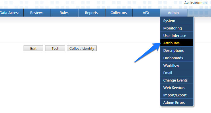
- Click User > Edit, as shown in Figure 7‑4.
Figure 7‑4 IMG Edit User
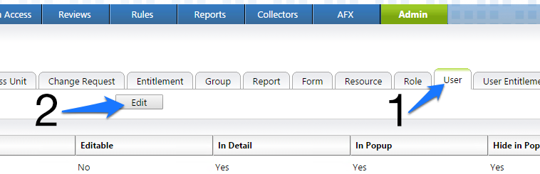
- Modify your user attributes to match Figure 7‑5 through Figure 7‑7.
Figure 7‑5 IMG User Attributes Examples (1 of 3)
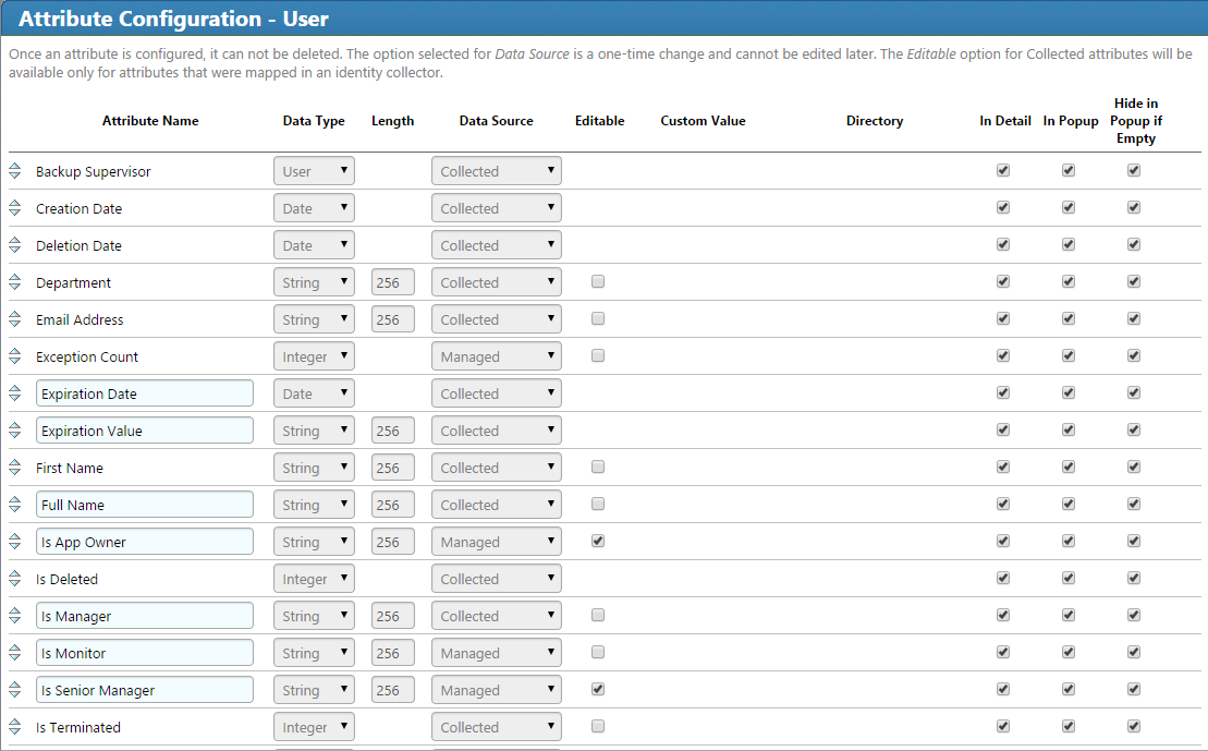
Figure 7‑6 IMG User Attributes Examples (2 of 3)
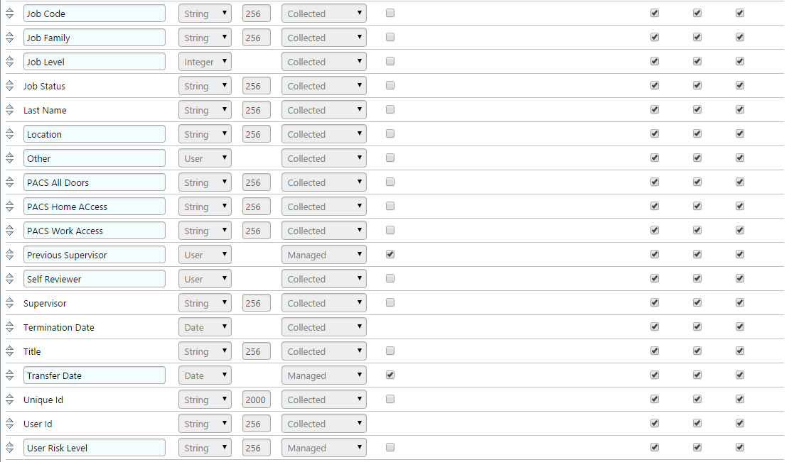
Figure 7‑7 IMG User Attributes Examples (3 of 3)
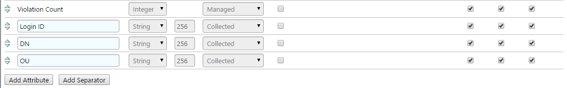
- Click OK.
- Click Account > Edit, as shown in Figure 7‑8.
Figure 7‑8 IMG Edit Attributes
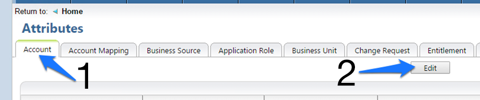
- Modify your account attributes to match those shown in Figure 7‑9.
Figure 7‑9 IMG Account Attributes Example
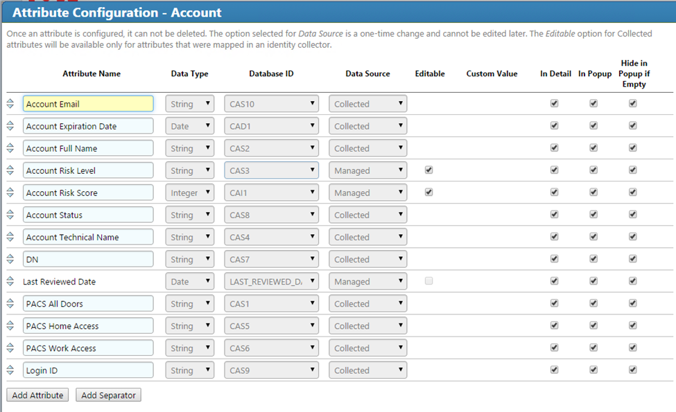
- Click OK.
7.3.2. Set Up Organization Users
The next step is to set up the organization’s existing users. In the example solution, we used a CSV file that contains all of the users in the organization. This CSV file needs to be copied to a convenient location on the IMG server. You can get a sample CSV file, HR_Data_Move.csv, at https://www.nccoe.nist.gov/sites/default/files/library/sp1800/es-idam-nist-sp1800-2-draft.zip.
Once the CSV file is copied to the server, perform the following actions:
- Navigate to Resources, and select Directories, as shown in Figure 7‑10.
Figure 7‑10 IMG Resources Directories
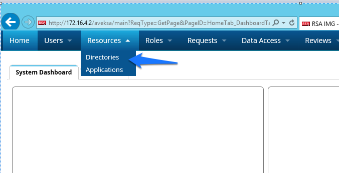
- Click Create Directory, as shown in Figure 7‑11.
Figure 7‑11 IMG Create Directory
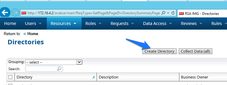
- Select Other Directory, and then click Next, as shown in Figure 7‑12.
Figure 7‑12 IMG Create Directory
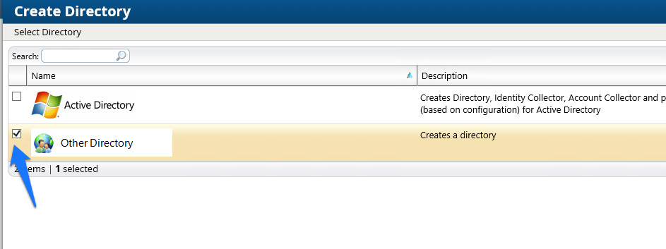
- Enter
HRin the Directory Raw Name field. Click Finish, as shown in Figure 7‑13.
Figure 7‑13 IMG Directory Information
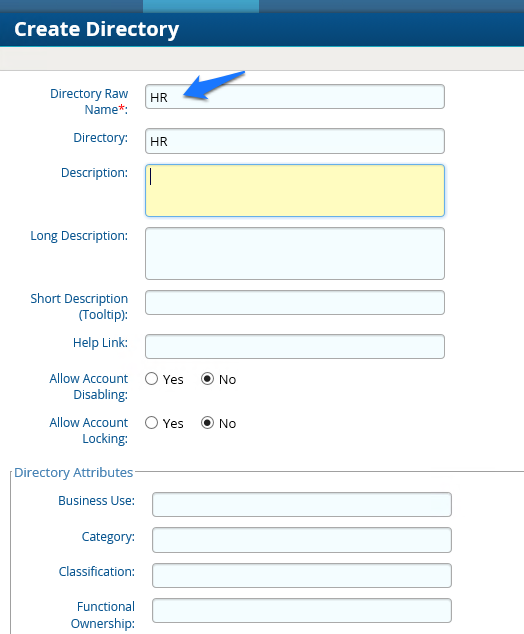
You have now created your first directory, which will serve as a repository for all of the HR data for the organization.
Repeat the above steps to create a second directory. This second directory will be named “RSA Adaptive Directory.” This container will be used to pull AD accounts from the Adaptive Directory server. In this case, be sure to select the two options highlighted in Figure 7‑14.
Figure 7‑14 IMG Create Directory
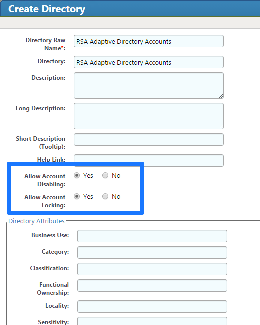
7.3.3. Populate the HR Directory
The next step is to populate the HR directory with users.
- Click Resources > Directories, as shown in Figure 7‑15.
Figure 7‑15 IMG Directories
- Click on the new HR directory that you just created, as shown in Figure 7‑16.
Figure 7‑16 IMG Directories

- Click on Collectors > Create Identity Collector, as shown in Figure 7‑17.
Figure 7‑17 IMG Create Identity Collector
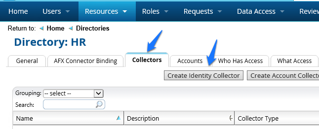
- Enter details as shown in Figure 7‑18.
Figure 7‑18 IMG HR Identities
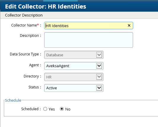
- Click Next, and then enter details as shown in Figure 7‑19.
Figure 7‑19 IMG HR Identities (cont.)
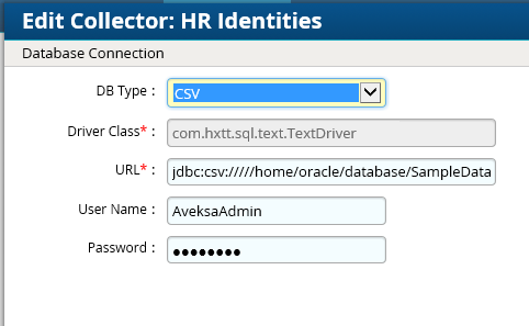
Use the same username and password that you use to log into the IMG management web page.
The URL will point to the folder in which the CSV file is located. In this example, the full field is jdbc:csv://///home/oracle/database/SampleData/Demo/HR/?_CSV_Header=true;tmpdir=/home/oracle.
The CSV file is located in home/oracle/database/SampleData/Demo/HR.
Click Next.
Leave Users selected, as shown in Figure 7‑20, and then click Next.
Figure 7‑20 IMG HR Identities – Users
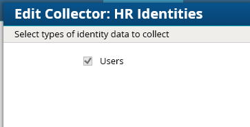
- Enter details as shown in Figure 7‑21 and Figure 7‑22. The full text of the User Data Query is as follows:
select fname, lname, user_num, ou, login, email as sAMAccountName, email, location, bu, department, title, supervisor, job_level, job_status, login as SR, is_terminated, previous_manager, jobcode, previous_manager as backjp_supervisor, job_family,concat(lname,', ',fname)as fullname, is_manager, email as UniqueID from HR_Data_Move
Figure 7‑21 IMG HR Identities
Figure 7‑22 IMG HR Identities (Continued)
- Click Finish.
Now we can configure the Adaptive Directory Container with Identity and Account collectors.
7.3.4. Configure Adaptive Directory Container
The next step is to configure the Adaptive Directory Container with Identity and Account collectors.
- Navigate to the Adaptive Directory Container, as shown in Figure 7‑23 (Resources > Directories > RSA Adaptive Directory Accounts).
Figure 7‑23 IMG Adaptive Directory Container
This identity collector will tie together user identities in Adaptive Directory to user identities in the HR CSV file.
- Click on Collectors > Create Identity Collector, as shown in Figure 7‑24.
Figure 7‑24 IMG Identity Collector
- Create the ID collector as follows, clicking Next between each screenshot shown in Figure 7‑25 through Figure 7‑29.
Figure 7‑25 IMG AD Identity Collector (1 of 5)
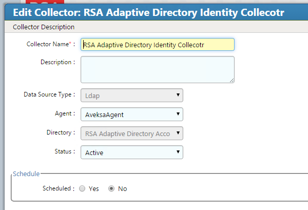
Figure 7‑26 IMG AD Identity Collector (2 of 5)
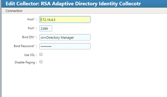
Figure 7‑27 IMG AD Identity Collector (3 of 5)
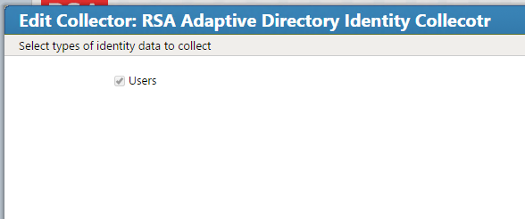
Figure 7‑28 IMG AD Identity Collector (4 of 5)
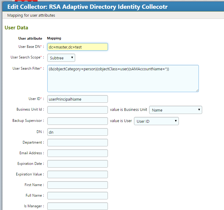
Figure 7‑29 IMG AD Identity Collector (5 of 5)
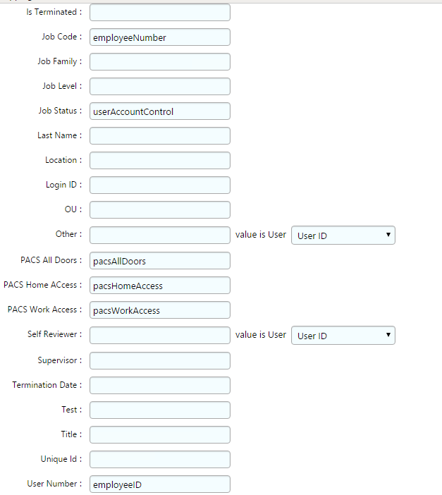
- Click Finish.
7.3.5. Create an Account Collector
The next step is to create an account collector, which pulls all relevant attributes from Adaptive Directory.
- Click on Collectors > Create Account Collector, as shown in Figure 7‑30.
Figure 7‑30 IMG AD Create Account Collector
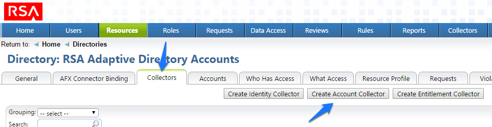
- Create the account collector as follows, clicking Next between each screenshot shown in Figure 7‑31 through Figure 7‑40.
Figure 7‑31 IMG Edit Collector (1 of 10)
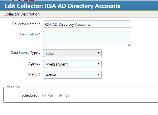
Figure 7‑32 IMG Edit Collector (2 of 10)
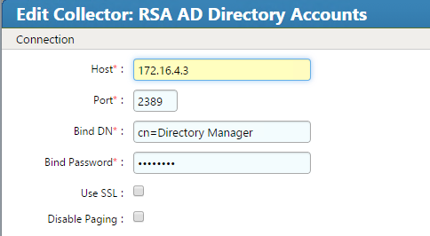
Figure 7‑33 IMG Edit Collector (3 of 10)
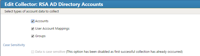
Figure 7‑34 IMG Edit Collector (4 of 10)
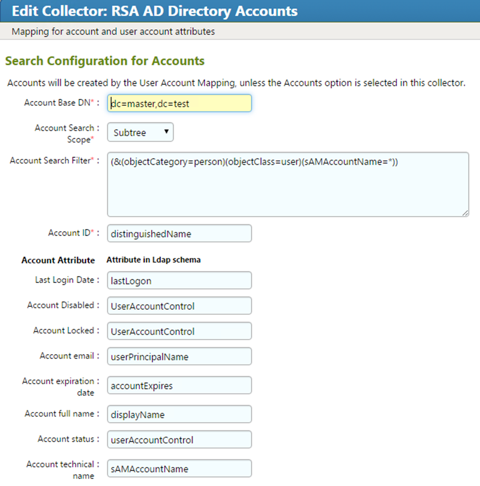
Figure 7‑35 IMG Edit Collector (5 of 10)
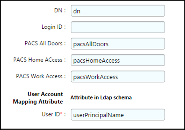
Figure 7‑36 IMG Edit Collector (6 of 10)
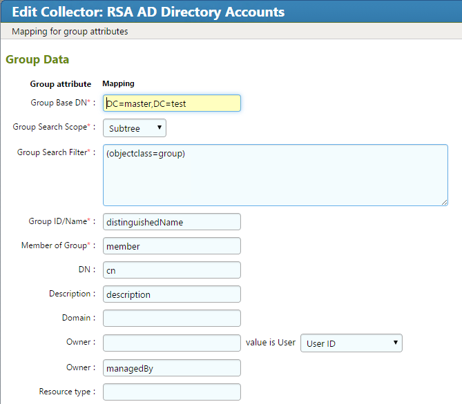
Figure 7‑37 IMG Edit Collector (7 of 10)
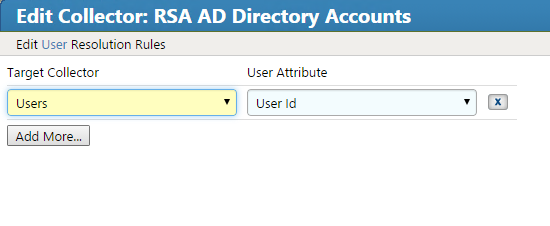
Figure 7‑38 IMG Edit Collector (8 of 10)
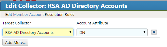
Figure 7‑39 IMG Edit Collector (9 of 10)
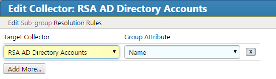
Figure 7‑40 IMG Edit Collector (10 of 10)
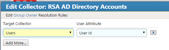
Click Finish.
A Test button is provided with each account collector and identity collector.
Test each account collector that you created using the Test button. This action verifies that IMG can retrieve the account information for each directory added, as shown in Figure 7‑41.
Figure 7‑41 IMG Account Test
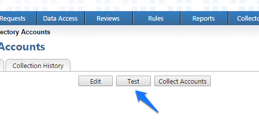
A successful test will look something like Figure 7‑42.
Figure 7‑42 IMG Successful Test Example
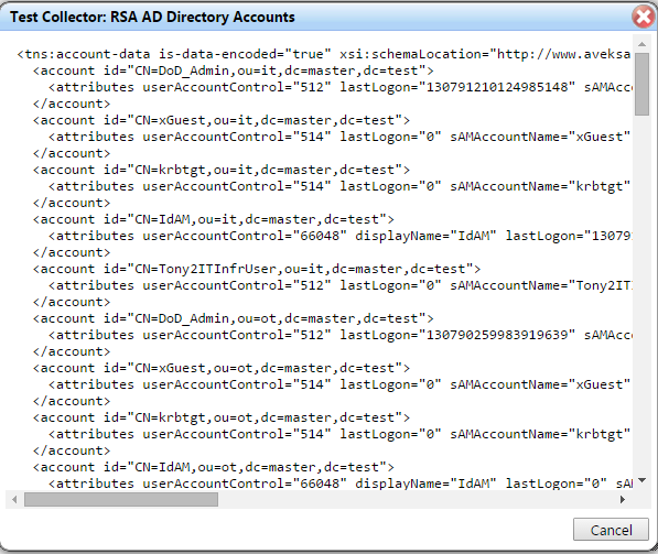
In Figure 7‑42 above, you can see valid data in an EXtensible Markup Language (XML) format. A failed test will generate an error message that can help you isolate the problem.
7.3.6. Edit the Unification Configuration Participating Collectors
The next step is to configure Unification; this is the process of joining Identities from the HR CSV and the Adaptive Directory collectors.
- Click on Collectors > Unification Config, as shown in Figure 7‑43.
Figure 7‑43 IMG Unification Configuration
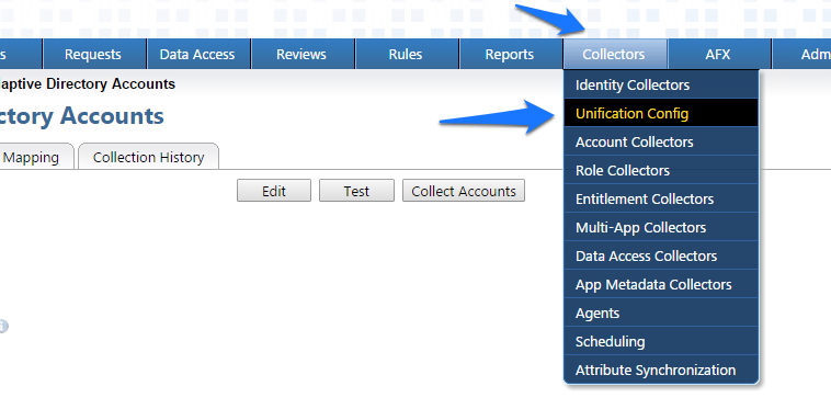
- Choose the Participating Collectors tab, and then click Edit, as shown in Figure 7‑44.
Figure 7‑44 IMG Participating Collectors
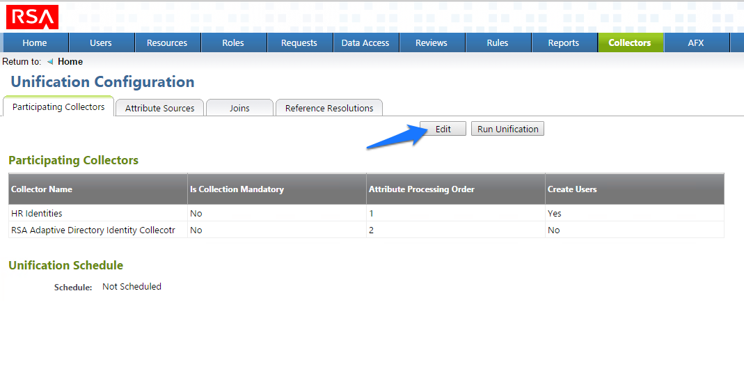
- Configure as shown in Figure 7‑45 and Figure 7‑46, and then click Next on each screen.
Figure 7‑45 IMG Edit Participating Collectors
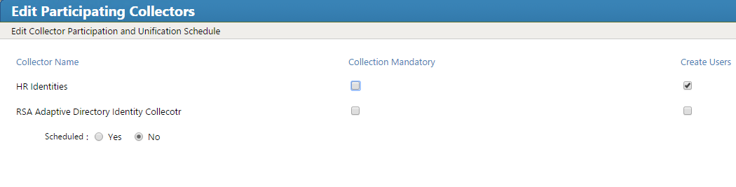
Figure 7‑46 IMG Edit Participating Collectors (Continued)
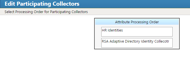
In the above example, we have HR Identities at the top. This indicates that HR Identities is an authoritative source. If there are any discrepancies between the data between two sources, then the one at the top will win by default; however, this can be overridden, as later discussed.
- Click Finish.
7.3.7. Edit User Attribute Source
The next step is to change the default behavior of the authoritative source for the necessary attributes.
- Choose the Attribute Sources tab, and then click Edit, as shown in Figure 7‑47.
Figure 7‑47 IMG Unification Configuration Attribute Sources
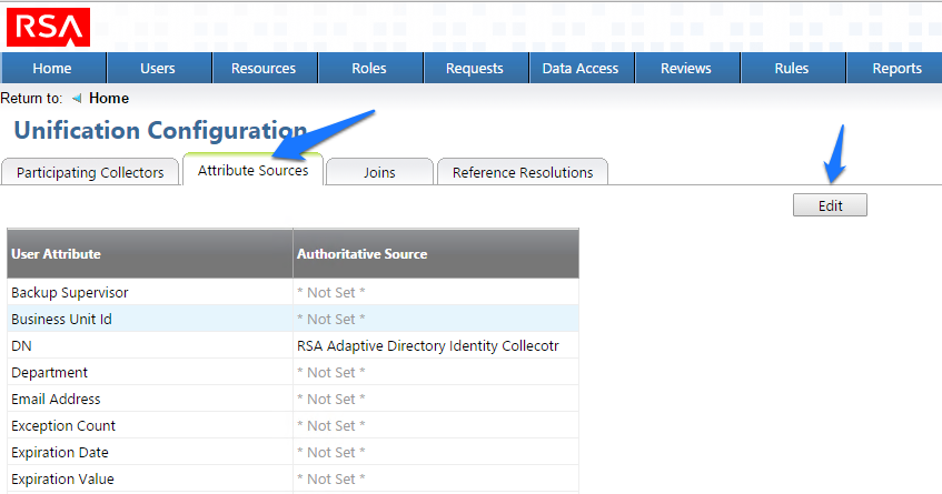
- Edit the Attributes as shown in Figure 7‑48 and Figure 7‑49. Leave alone any attribute shown as *Not Set*; these attributes will use the default behavior.
Figure 7‑48 IMG Edit User Attribute Mapping
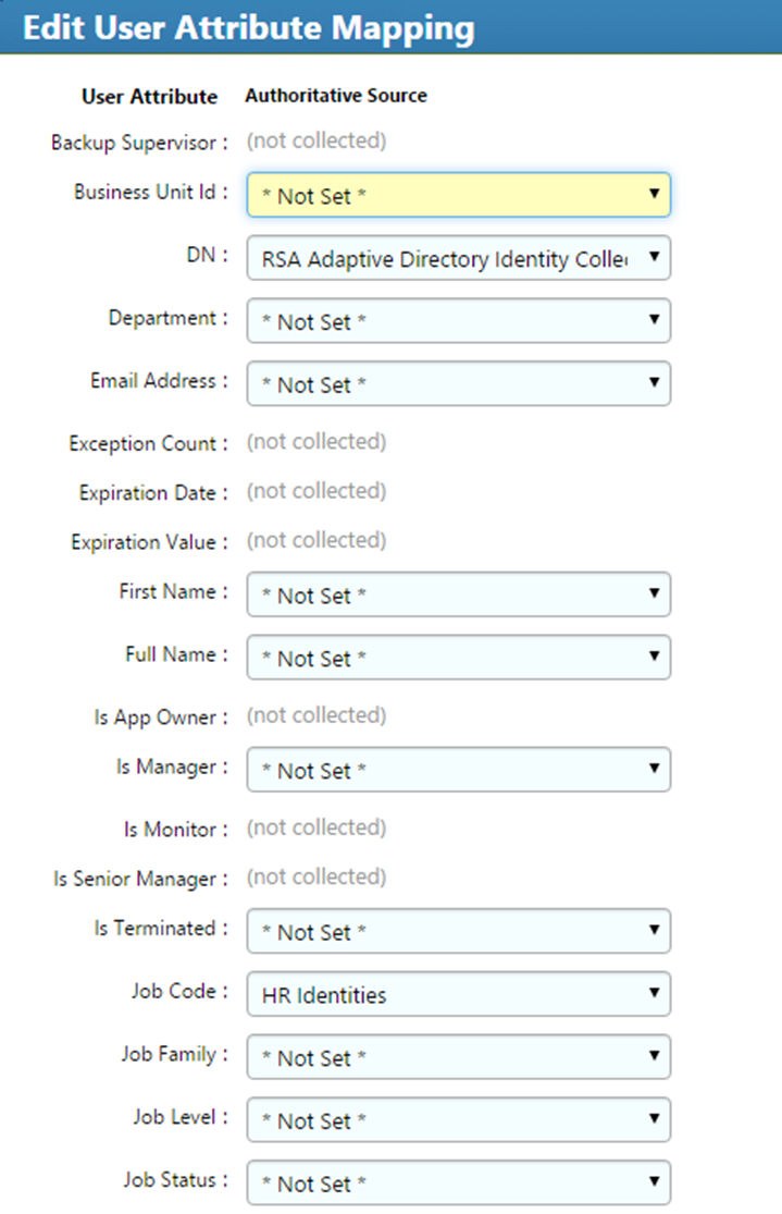
Figure 7‑49 IMG Edit User Attribute Mapping (Continued)
- Click OK.
7.3.8. Edit Unification Configuration Attribute Source
The next step is to configure which attribute to use from each directory so that IMG knows how to tie users together.
- Click Joins > Edit, as shown in Figure 7‑50.
Figure 7‑50 IMG Unification Configuration Joins
- Choose HR Identities from the Primary Identity Collector drop-down box, as shown in Figure 7‑51.
Figure 7‑51 IMG Edit Joins
- Click Finish.
7.3.9. Start Data Collection
The next step is to start collecting identity data.
- From the home page, choose Resources > Directories. Click the Collect Data (all) button, as shown in Figure 7‑52.
Figure 7‑52 IMG Start Data Collection
- Click OK on the next window, as shown in Figure 7‑53.
Figure 7‑53 IMG Collect Data
- The process will take 30 seconds or so to complete. You can check the progress by going to Admin > Monitoring, as shown in Figure 7‑54.
Figure 7‑54 IMG Data Collection Monitoring
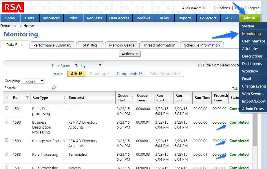
You will see the status of all of the processes change to Completed when done.
7.3.10. Review Data Collected
Now you can look at this data by going to Users > Users > Groups.
- From the home page, choose Users > Users > Groups, as shown in Figure 7‑55, to review the data collected.
Figure 7‑55 IMG Data Collection Review
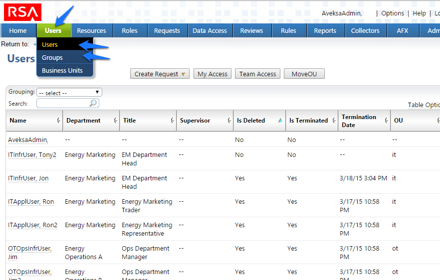
7.3.11. Configure Business Rules
The next step is to configure Business Roles.
- Click on Roles > Roles, as shown in Figure 7‑56.
Figure 7‑56 IMG Roles
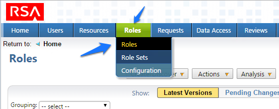
- Click Create/Discover > Discover Roles, as shown in Figure 7‑57.
Figure 7‑57 IMG Discover Roles
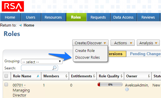
- Configure as shown in Figure 7‑58 through Figure 7‑60.
Figure 7‑58 IMG Discover Roles (1 of 3)
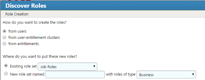
Figure 7‑59 IMG Discover Roles (2 of 3)
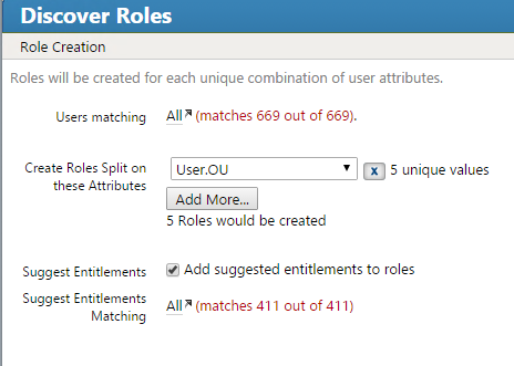
Figure 7‑60 IMG Discover Roles (3 of 3)
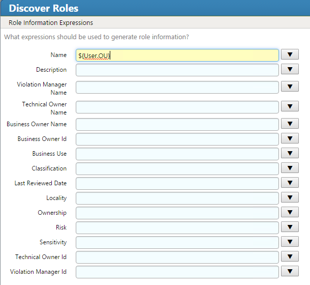
- Notice how there are some duplicates; the job codes are the same, but the descriptions are slightly different. You can combine these rolls into one, as shown in Figure 7‑61.
Figure 7‑61 IMG Discover Roles – Combining
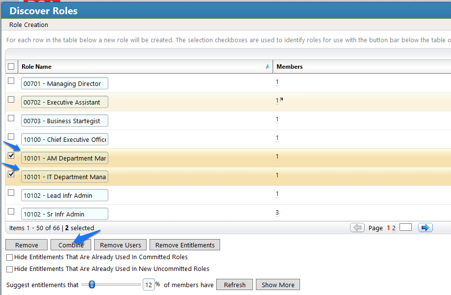
- When you are done combining duplicates, click Finish.
7.3.12. Create Automated Rules
The next steps create rules for automatically detecting and invoking workflows for new users and terminations.
- Click on Rules and Definitions, as shown in Figure 7‑62.
Figure 7‑62 IMG Roles Definitions
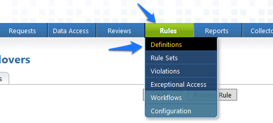
- Click on Create Rule, and configure as shown in Figure 7‑63 and Figure 7‑64 for new users.
Figure 7‑63 IMG New User
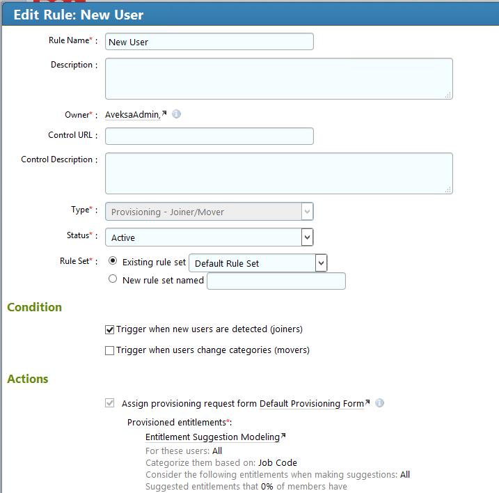
Figure 7‑64 IMG New User
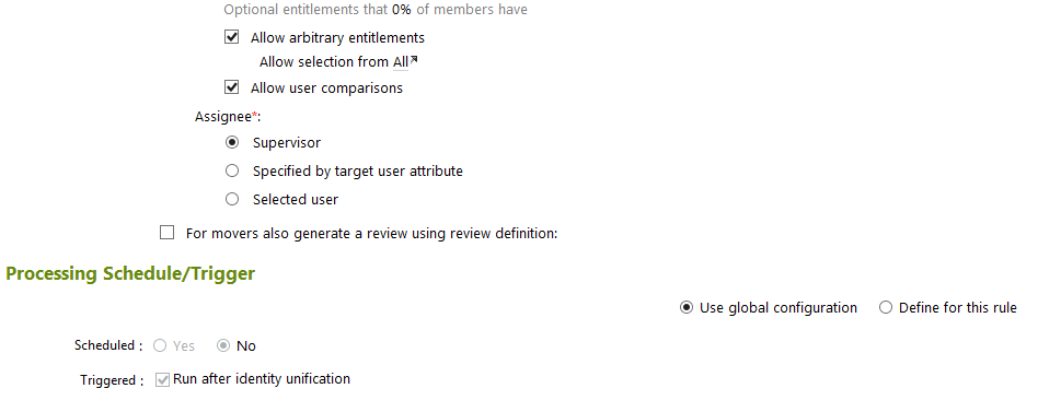
- Click on Create Rule, and configure as shown in Figure 7‑65 and Figure 7‑66 for user terminations.
Figure 7‑65 IMG User Termination
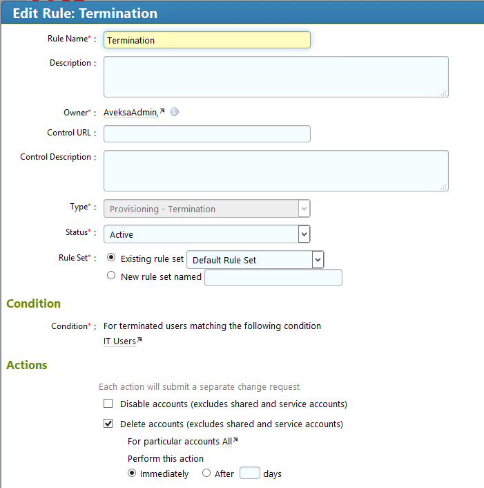
Figure 7‑66 IMG User Termination (Continued)
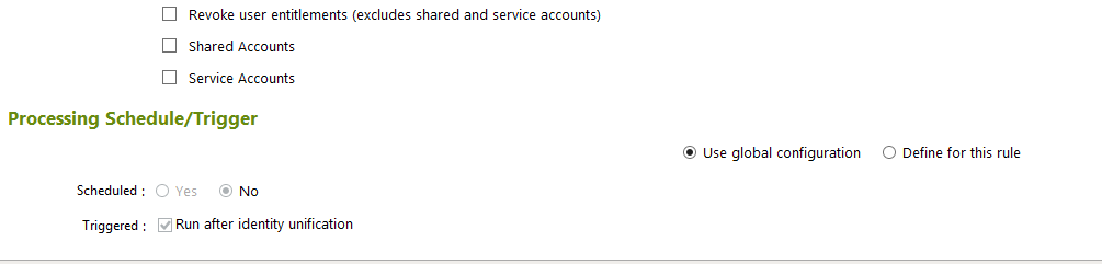
- Click OK.
7.3.13. Create Provisioning Template
The next step is to create a template that IMG uses when provisioning accounts in Adaptive Directory.
- Click on Requests > Configuration > Account Template > Create Account Template, as shown in Figure 7‑67.
Figure 7‑67 IMG Request Configuration
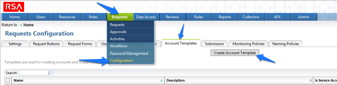
- Enter a name, and click OK, as shown in Figure 7‑68.
Figure 7‑68 IMG Account Template
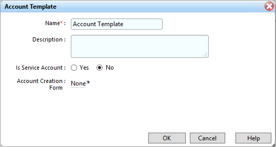
- Click on the name of the account template that you just created, and add parameters as shown in Figure 7‑69.
Figure 7‑69 IMG IT Account Template
- Click Resources > Directories > RSA Adaptive Directory Accounts, and then make the following changes to the Requests tab, as shown in Figure 7‑70.
Figure 7‑70 IMG AFX Connectors
7.3.14. Configure AFX Module
The next step is to configure the IMG AFX module, which will allow IMG to provision to Adaptive Directory.
- Click on AFX > Connectors, as shown in Figure 7‑71.
Figure 7‑71 IMG AFX Connectors
- Click on Create Connector, as shown in Figure 7‑72.
Figure 7‑72 IMG Create Connector
- Configure the General tab as shown in Figure 7‑73.
Figure 7‑73 IMG AD Connector AFX Server: General
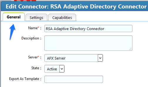
- Configure the Settings tab as shown in Figure 7‑74 through Figure 7‑76.
Figure 7‑74 IMG AD Connector AFX Server: Settings (1 of 3)
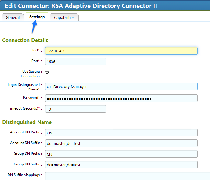
Figure 7‑75 IMG AD Connector AFX Server: Settings (2 of 3)
Figure 7‑76 IMG AD Connector AFX Server: Settings (3 of 3)
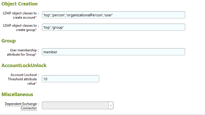
- Configure the Capabilities tab as shown in Figure 7‑77.
Figure 7‑77 IMG AD Connector AFX Server: Capabilities
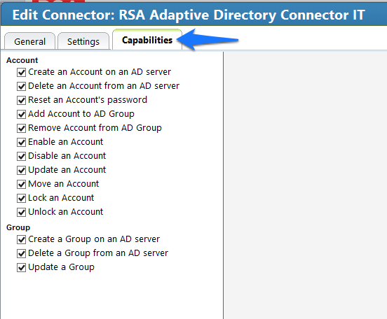
- Check all capabilities that are needed for the connector. Once all are selected, click on the capability name, one by one, and configure as shown in Figure
- 7‑78 through Figure 7‑90.
Figure 7‑78 IMG AD Connector IT Capability Configuration (1 of 13)
Figure 7‑79 IMG AD Connector IT Capability Configuration (2 of 13)
Figure 7‑80 IMG AD Connector IT Capability Configuration (3 of 13)
Figure 7‑81 IMG AD Connector IT Capability Configuration (4 of 13)
Figure 7‑82 IMG AD Connector IT Capability Configuration (5 of 13)
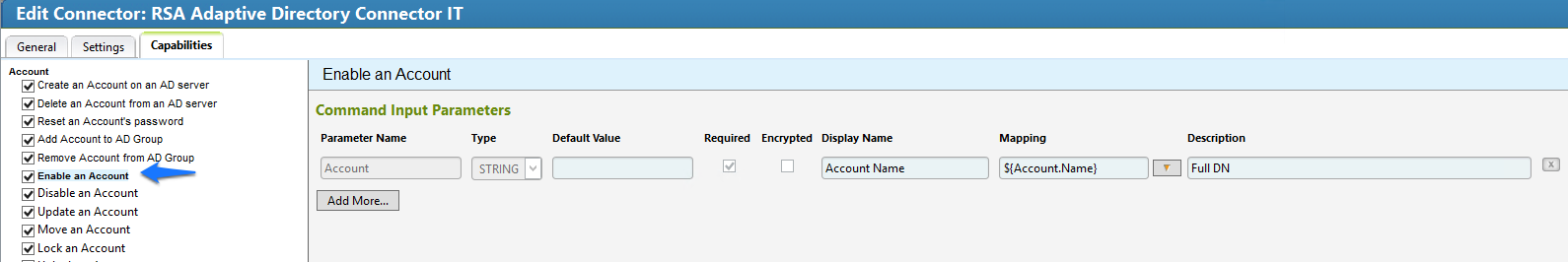
Figure 7‑83 IMG AD Connector IT Capability Configuration (6 of 13)
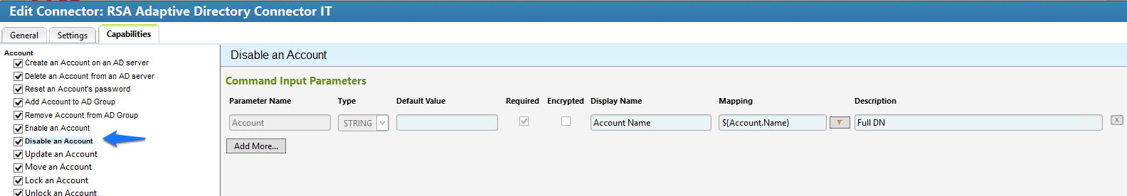
Figure 7‑84 IMG AD Connector IT Capability Configuration (7 of 13)
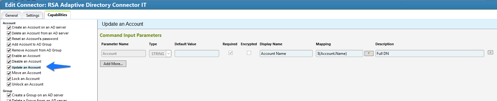
Figure 7‑85 IMG AD Connector IT Capability Configuration (8 of 13)
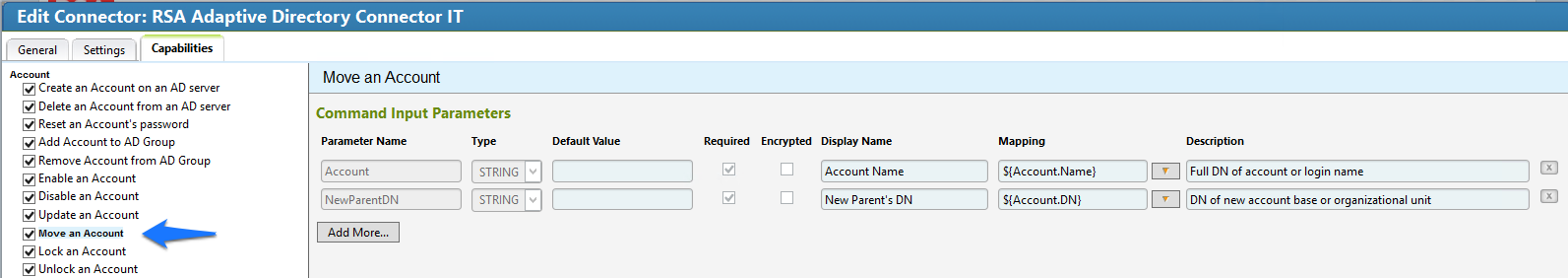
Figure 7‑86 IMG AD Connector IT Capability Configuration (9 of 13)
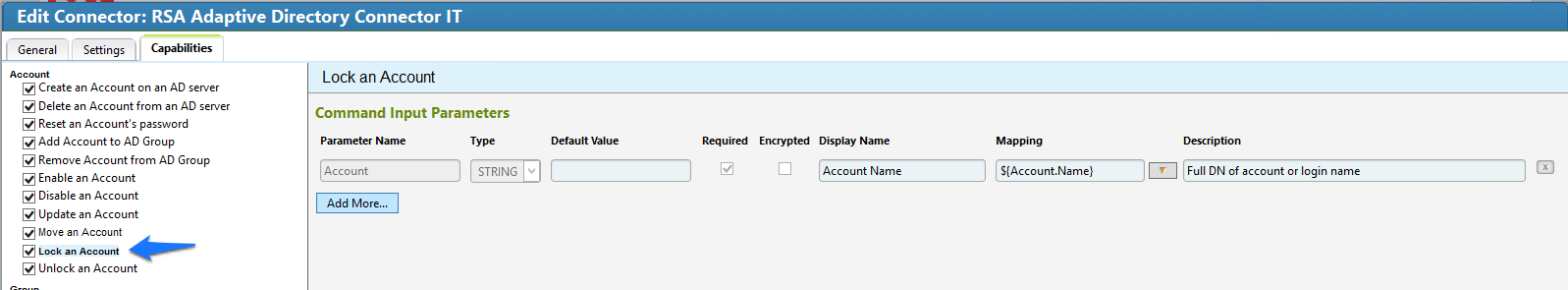
Figure 7‑87 IMG AD Connector IT Capability Configuration (10 of 13)
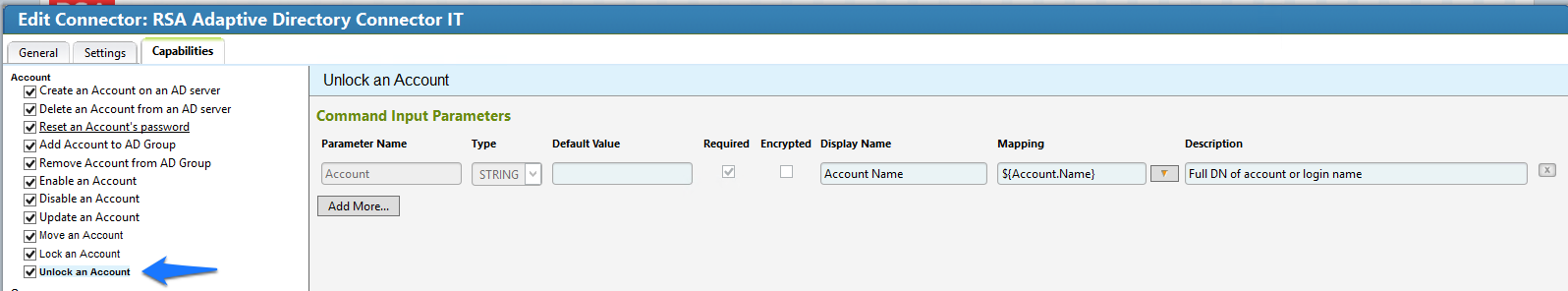
Figure 7‑88 IMG AD Connector IT Capability Configuration (11 of 13)
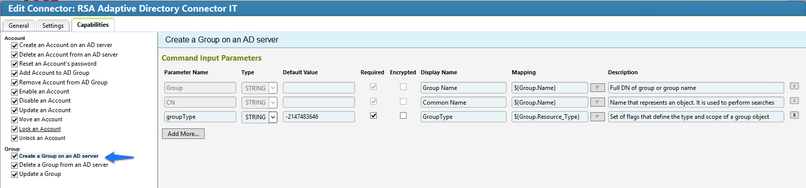
Figure 7‑89 IMG AD Connector IT Capability Configuration (12 of 13)
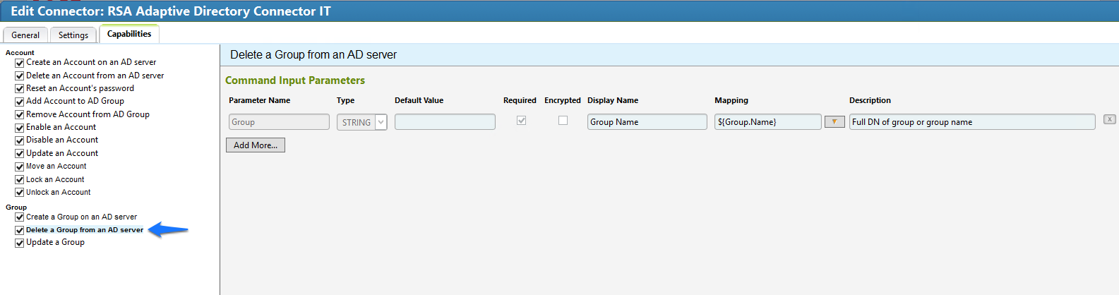
Figure 7‑90 IMG AD Connector IT Capability Configuration (13 of 13)
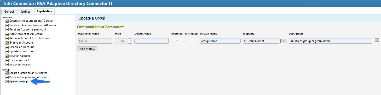
- Click OK.
7.3.15. Configure Adaptive Directory to Use AFX Connector
The next step is to configure the RSA Adaptive Directory “Directory” to use the new AFX Connector.
- Click Resources > Directories, select RSA Adaptive Directory Accounts, and then click OK, as shown in Figure 7‑91.
Figure 7‑91 IMG Resources Directories
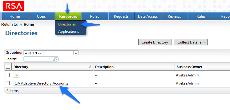
- In the next window, click AFX Connector Binding > Edit Connector Binding, as shown in | Figure 7‑92.
Figure 7‑92 IMG AD Accounts
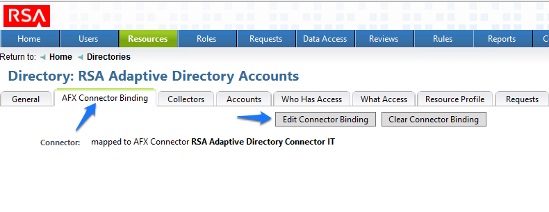
- Click OK, as shown in Figure 7‑93.
Figure 7‑93 IMG AD AFX Connector Binding
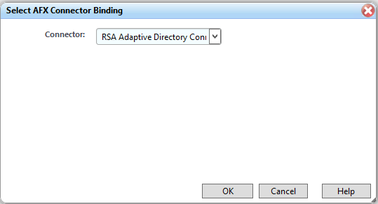
The system is now ready.
7.3.16. Adding a New User
To add a new user, you will need to open the HR CSV file.
- Go to Resources > Directories > Collect Data (all), as shown in Figure 7‑94.
Figure 7‑94 IMG Resources Directories
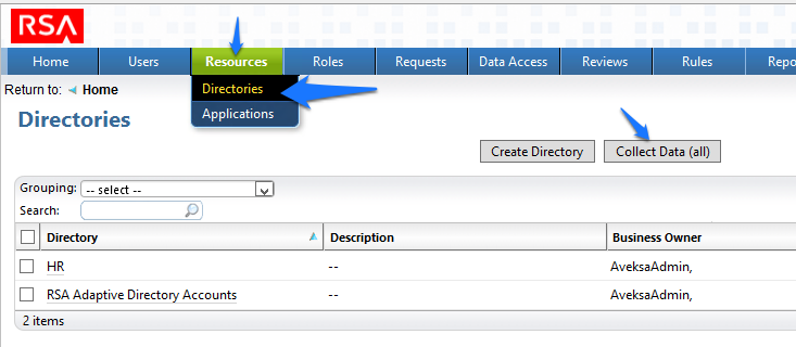
- Click OK, as shown in Figure 7‑95.
Figure 7‑95 IMG Collect Data
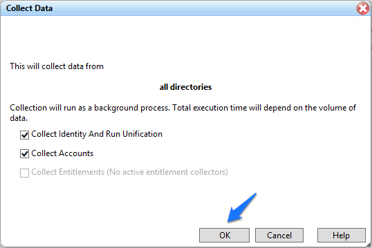
- After about 30 seconds, go to Requests > Activities, and click Perform next to the request to add a new user, as shown in Figure 7‑96.
Figure 7‑96 IMG Requests Activities
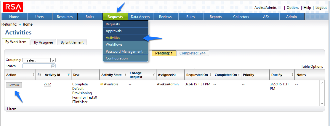
- Select a group to which you would like to add the user, and then click Next > Accepted, as shown in Figure 7‑97.
Figure 7‑97 IMG Accepted Access Request
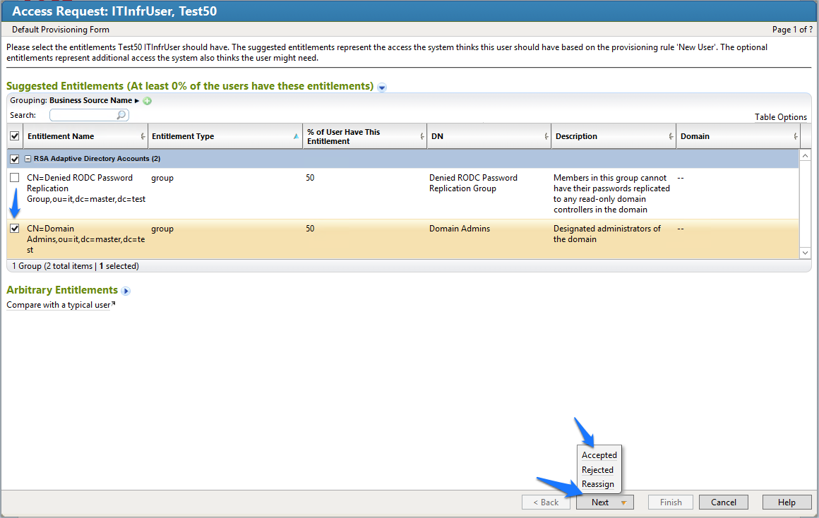
- Enter a description, if you wish, and then click Finish.
- Go to Requests > Requests, and then select the name of the request, as shown in Figure 7‑98.
Figure 7‑98 IMG Requests
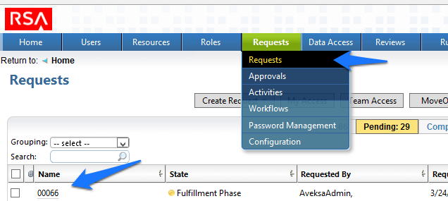
- After about 30 seconds, your new user will be provisioned to AD and will be added to the group that you selected, as shown in Figure 7‑99.
Figure 7‑99 IMG New User Provisioned
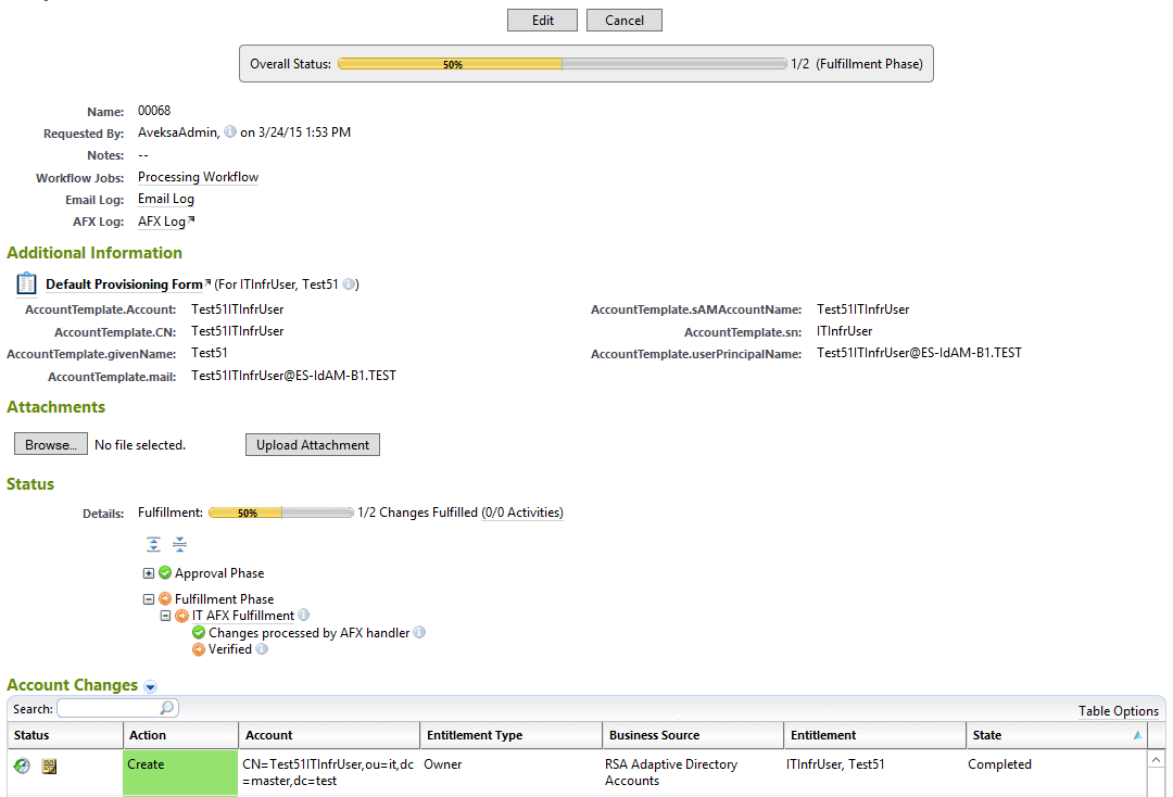
Note: The state of the group add will remain as pending, and the overall status will remain at 50%, until you recollect data from the Directories page so that IMG can detect that the user has been added to the group successfully, as shown in Figure 7‑100.
Figure 7‑100 IMG Successful User Add
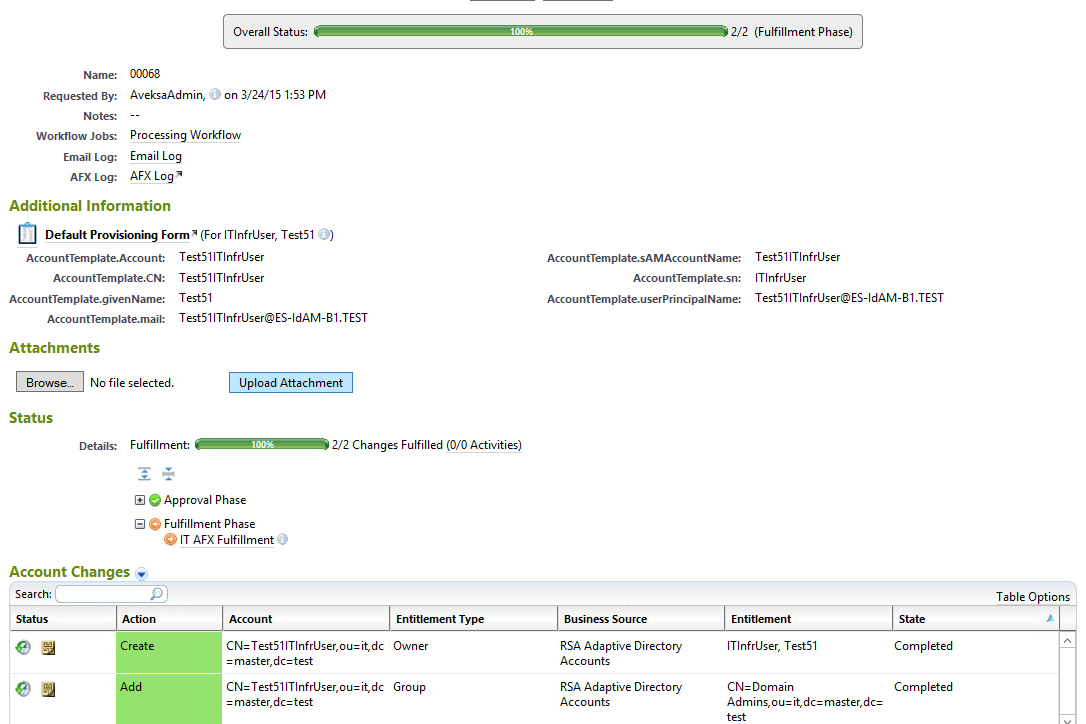
7.3.17. Moving a User
- Open your CSV file, and change the attribute that defines the organizational unit (OU) of the user to a different OU.
- Collect data again.
- The OU change is detected, and IMG deletes the user from the original OU and adds the user to the new OU.
- Go to Requests > Activities, and click Perform, as shown in Figure 7‑101.
Figure 7‑101 IMG Requests Activities
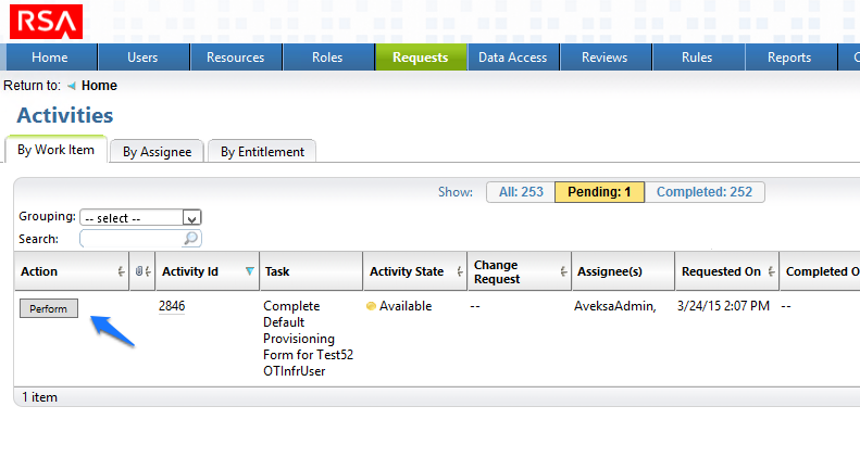
- Select the group to which you would like the moved user to have access, click Next > Accepted, and then click Finish on the final screen, as you did before when adding a new user.
- Collect data again so that IMG can confirm that the user is added to the appropriate group in the new OU.
7.3.18. Terminating a User
- Delete the user from the HR CSV file.
- Collect data again.
- The user is automatically removed.
- Collect data again so that IMG can confirm that the user is no longer in Adaptive Directory.
- Go to Requests > Requests, and check the Status, as shown in Figure 7‑102.
Figure 7‑102 IMG Request Status
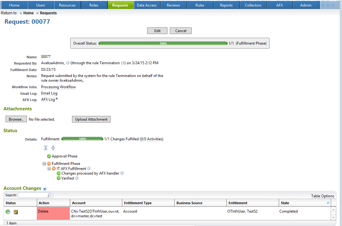
7.3.19. User Attribute Synchronization
- Choose Collectors > Attribute Synchroniation, as shown in Figure 7‑103.
Figure 7‑103 IMG User Synchronization Menu Item
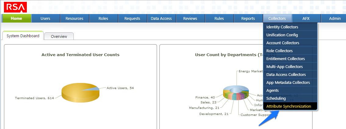
- Configure as shown in Figure 7‑104.
Figure 7‑104 IMG User Synchronization Status
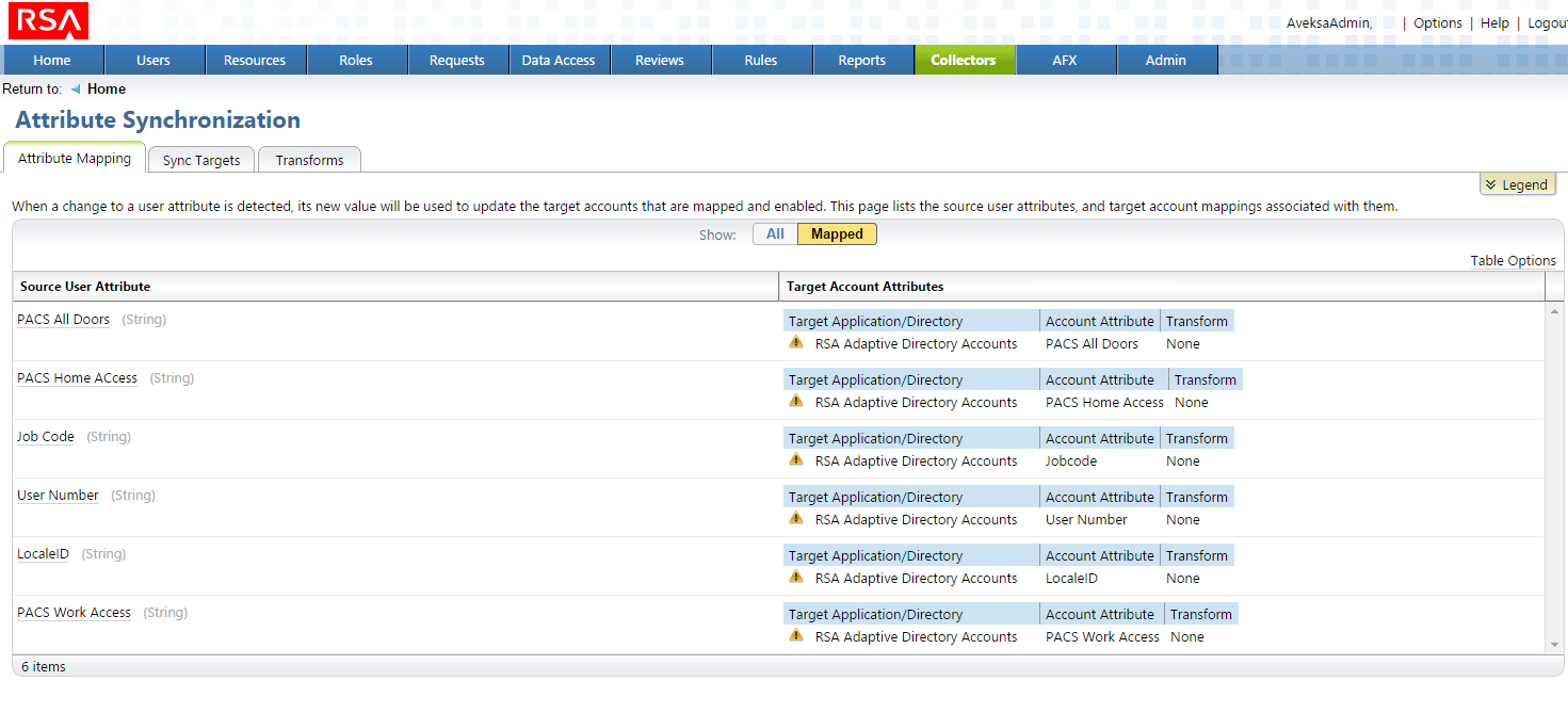
The IMG installation is now complete.
8. Adaptive Directory: RSA (Build #2)
The RSA Adaptive Directory implements the central IdAM identity store in Build #2. It receives input from the central IdAM system (RSA IMG). The central identity store contains the distribution mechanism for updating the various downstream (synchronized) directories with user access and authorization data. This process applies to new users, terminated users (disabled or deleted users), and any changes to a user profile. Changes include promotions, job responsibility changes, and any other change that would affect the systems that a user needs to access.
8.1. Security Characteristics
Cybersecurity Framework Categories: PR.AC-1: Identities and credentials are managed for authorized devices and users.
NIST SP 800-53 Revision 4 Security Controls: AC-2, IA Family
8.2. RSA Adaptive Directory Is Installed on the IdAM Network, on a VM That Is Running CentOS 7
The following lines detail the command‑line installation procedure for the RSA Adaptive Directory, including displayed responses:
[root@localhost ~]# ls
anaconda-ks.cfg  reports  xml
[root@localhost ~]# cd ..
[root@localhost /]# ls
bin   dev  home  lib64  mnt  proc  run   srv  tmp  var
boot  etc  lib   media  opt  root  sbin  sys  usr
[root@localhost /]# cd media
[root@localhost media]# ls
cdrom
[root@localhost media]# cd cdrom
[root@localhost cdrom]# ls
Documentation  rsa_7.1.5_linux_64.bin  rsa_7.1.5_windows_64.exe
[root@localhost cdrom]# su root ./rsa_7.1.5_linux_64.bin
Preparing to install...
WARNING: /tmp does not have enough disk space!
        Attempting to use /root for install base and tmp dir.
Extracting the JRE from the installer archive...
Unpacking the JRE...
Extracting the installation resources from the installer archive...
Configuring the installer for this system's environment...
Launching installer...
Graphical installers are not supported by the VM. The console mode will be used instead...
========================================================================
RSA Adaptive Directory 7.1.5                     (created with InstallAnywhere)
-------------------------------------------------------------------------------
Preparing CONSOLE Mode Installation...

========================================================================
License Agreement
-----------------
Please read the following License Agreement carefully.
LICENSE AGREEMENT
*** IMPORTANT INFORMATION - PLEASE READ CAREFULLY ***
(…Lic agreement text omitted…)
DO YOU ACCEPT THE TERMS OF THIS LICENSE AGREEMENT? (Y/N): Y
========================================================================
Choose Install Folder
---------------------
Please choose a destination folder for this installation
Where would you like to install?
Default Install Folder: /root/rsa/adaptivedirectory
ENTER AN ABSOLUTE PATH, OR PRESS  TO ACCEPT THE DEFAULT
    :
========================================================================
Choose Install Set
------------------
Please choose the Install Set to be installed by this installer.
->1- RSA Adaptive Directory New Cluster / Standalone
    2- RSA Adaptive Directory Cluster Node
    3- Customize...
ENTER THE NUMBER FOR THE INSTALL SET, OR PRESS  TO ACCEPT THE DEFAULT
:
========================================================================
New Cluster settings
--------------------
Enter information below about the new cluster to create:
- The cluster name
- The ZooKeeper ports that will be used
Cluster name: (DEFAULT: cluster1):
ZooKeeper Ensemble Port: (DEFAULT: 2888):
ZooKeeper Leader Election Port: (DEFAULT: 3888):
ZooKeeper Client Port: (DEFAULT: 2181):

========================================================================
Administrator name
------------------
Please provide the administrator name:
Admin User Name (DEFAULT: cn=Directory Manager):

========================================================================
Server administrator password
-----------------------------
Please provide a password for the administrator user :
Password (DEFAULT: ): secretsecret
Confirm Password (DEFAULT: ): secretsecret

========================================================================
Adaptive Directory port numbers
-------------------------------
Please enter port numbers for Adaptive Directory:
Adaptive Directory Port (DEFAULT: 2389):
Scheduler Port (DEFAULT: 1099):
Adaptive Directory SSL Port: (DEFAULT: 1636):

========================================================================
TLS Configuration
-----------------
Enable TLS (Y/N)? (DEFAULT: N):

========================================================================
Adaptive Directory HTTP port numbers
------------------------------------
Please enter port numbers for Adaptive Directory HTTP services:
Adaptive Directory HTTP Port (DEFAULT: 8089):
Adaptive Directory HTTPS Port (DEFAULT: 8090):

========================================================================
Certificate configuration
-------------------------
Use an existing certificate (Y/N)? (DEFAULT: N):

========================================================================
Application Server Configuration
--------------------------------
Enter information below to configure the Application Server
- Administrator user name for initial server instance.
- Administrator password for initial server instance (must be at least 8
characters in length).
- Administration server port number for initial server instance.
- HTTP/HTTPS port number for initial server instance.
- JMX port number for initial server instance.
Admin User (DEFAULT: admin):
Password (DEFAULT: ): secretsecret
Confirm Password (DEFAULT: ): secretsecret
Admin Port (DEFAULT: 4848):
HTTP Port (DEFAULT: 9090):
HTTPS Port (DEFAULT: 9191):
JMX Port (DEFAULT: 8686):

========================================================================
Control Panel Configuration
---------------------------
These are the settings for the web server hosting the control panel.
Enter the HTTP/HTTPS ports to configure the web server on the main instance:
HTTP Port (DEFAULT: 7070): These are the settings for the web server hosting the control panel.
Enter the HTTP/HTTPS ports to configure the web server on the main instance:
HTTPS Port (DEFAULT: 7171):
========================================================================
Port validation failed
----------------------
Control Panel HTTP port These are the settings for the Web Server hosting the
Control Panel. is invalid.
Please select a new one.
PRESS  TO ACCEPT THE FOLLOWING (OK):
========================================================================
Control Panel Configuration
---------------------------
These are the settings for the web server hosting the control panel.
Enter the HTTP/HTTPS ports to configure the web server on the main instance:
HTTP Port (DEFAULT: 7070):
HTTPS Port (DEFAULT: 7171):

========================================================================
Pre-Installation Summary
------------------------
Please Review the Following Before Continuing:
Product Name:
    RSA Adaptive Directory 7.1.5
Install Folder:
    /root/rsa/adaptivedirectory
Install Set:
    RSA Adaptive Directory New Cluster / Standalone
Product Features:
    Application,
    Sample Data
Java VM Installation Folder:
    /root/rsa/adaptivedirectory/jdk
Administrator User:
    cn=Directory Manager
Adaptive Directory Ports:
    2389 8089 8090
Scheduler Port:
    1099
SSL Configuration:
    1636
Start TLS Configuration:
    TLS is disabled.
Certificate Configuration:
    Self signed certificate.
App Server Configration:
    4848 9090 9191 8686
Web Server Configuration:
    7070 7171
Disk Space Information (for Installation Target):
    Required:  1,164.03 MegaBytes
    Available: 49,030.86 MegaBytes
PRESS  TO CONTINUE:
========================================================================
Installing...
-------------
[==================|==================|==================|==================]
[------------------|------------------|------------------|------------------]
========================================================================
Installation Complete
---------------------
Congratulations. RSA Adaptive Directory 7.1.5 has been successfully installed
to:
/root/rsa/adaptivedirectory
In order to start working with RSA Adaptive Directory 7.1.5, please follow
these steps:
- LOG OFF AND LOG IN AGAIN
- Copy and paste your license key when prompted after running RSA Adaptive
Directory 7.1.5
- Run /root/rsa/adaptivedirectory/bin/openControlPanel.sh
PRESS  TO EXIT THE INSTALLER:
8.3. Additional Steps Required After Installation Is Complete
After installation is complete, the next step is to install netstat: yum install net-tools.
Copy the license.lic file to /root/rsa/adaptivedirectory/vds_server.
Open all relevant firewall ports on the CentOS server.
Run
/root/rsa/adaptivedirectory/bin/openControlPanel.sh.Run
/root/rsa/adaptivedirectory/bin/runContextBuilder.sh.From a web browser, go to http:IPADDRESS:7070.
Start the server by clicking the Start button.
Click on the Tools menu item, and start the application server.
Configuration Procedure:
From a web browser, connect to the Adaptive Directory server, and log in (note the URL with port number) using the default credentials (see Figure 8‑1):
- Login:
cn=Directory Manager - Password:
secretsecret
- Login:
Figure 8‑1 Adaptive Directory Login Page
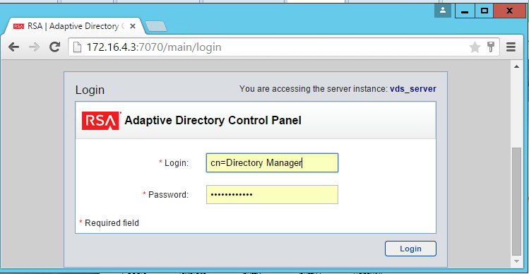
- On the main page, click Start to start the Adaptive Directory server (Figure 8‑2).
Figure 8‑2 Adaptive Directory Main Page
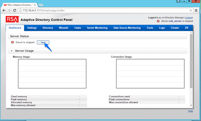
- On the Tools tab, click Start it to start the Persistent Cache service (Figure 8‑3).
Figure 8‑3 Adaptive Directory Tools Page
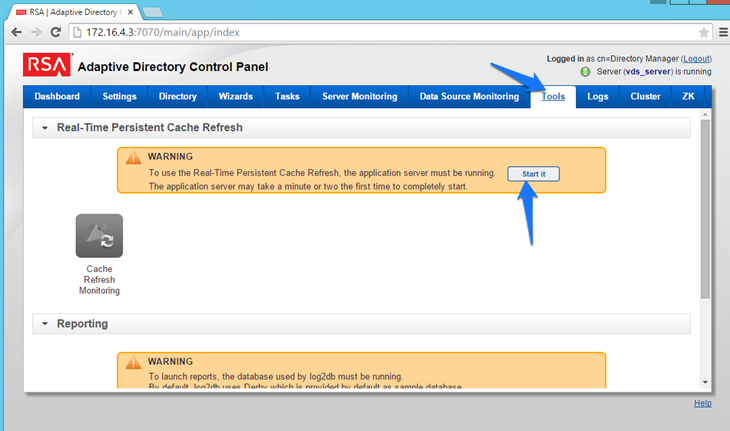
- Go to the Settings tab, click Server Backend Settings, and then click LDAP Data Sources | (Figure 8‑4).
Figure 8‑4 Adaptive Directory Server Backend Settings
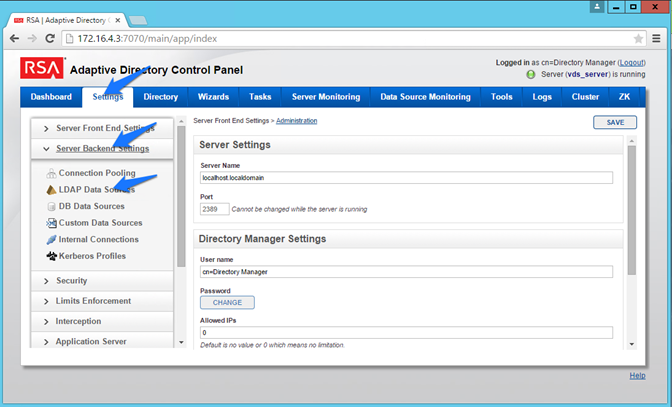
- Click Add.
- Enter details for your “backend AD,” as shown in Figure 8‑5. Click the TEST CONNECTION button to make sure that your settings are correct (Figure 8‑5). Repeat this process for all of the AD clusters (i.e., for the backend ADs on the IT, OT, and PACS networks). You can clone your first connection to make repeat additions easier.
Figure 8‑5 Adaptive Directory LDAP Data Source
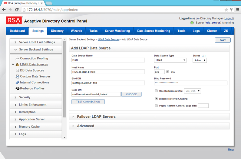
- Click on Directory > Configuration, right-click on Root Naming Contexts, and then select Naming Context, as shown in Figure 8‑6.
Figure 8‑6 Adaptive Directory Configuration of Naming Context
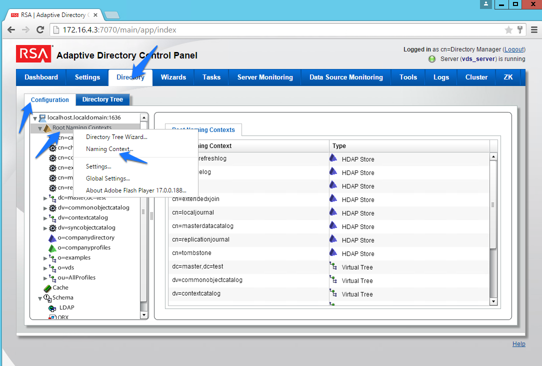
- You will be presented with the screen shown in Figure 8‑7. Enter the name that you would like your new Virtual LDAP directory to be configured with. Select Virtual Tree, and then click Next.
Figure 8‑7 Adaptive Directory New Naming Context
- Leave the defaults selected, as shown in Figure 8‑8, and then click OK.
Figure 8‑8 Adaptive Directory Configure Virtual Tree
You now have a virtual directory naming context. You will see the screen shown in Figure 8‑9.
Figure 8‑9 Adaptive Directory Virtual Tree
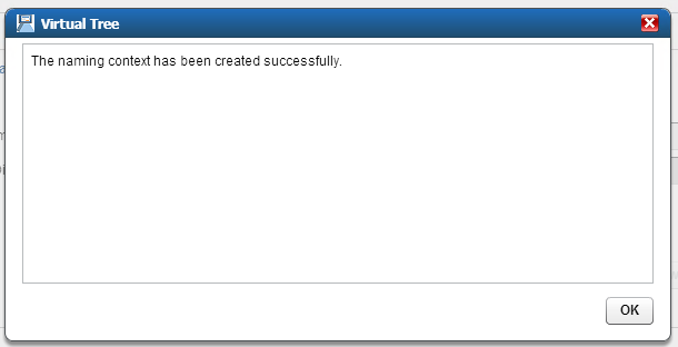
The next step is to configure this virtual directory to include all of the backend AD clusters.
- Right-click on your newly created Virtual Directory, and select New Level, as shown in Figure 8‑10.
Figure 8‑10 Adaptive Directory Create New Level
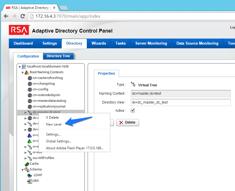
- Enter a name for this LDAP backend mapping. This name will be an OU in the Virtual Directory, as shown in Figure 8‑11.
Figure 8‑11 Adaptive Directory New Level Name
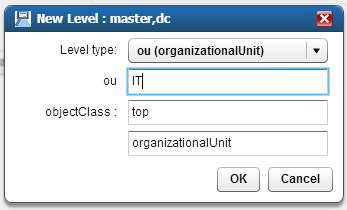
- Right-click this new OU in your Virtual Directory, and select Backend Mapping, as shown in | Figure 8‑12.
Figure 8‑12 Adaptive Directory Backend Mapping
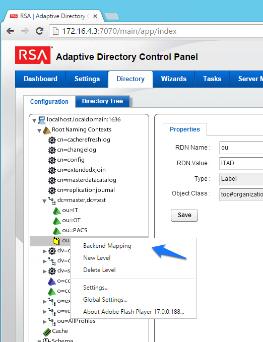
- Leave LDAP Backend selected, and click Next, as shown in Figure 8‑13.
Figure 8‑13 Adaptive Directory Backend Mapping
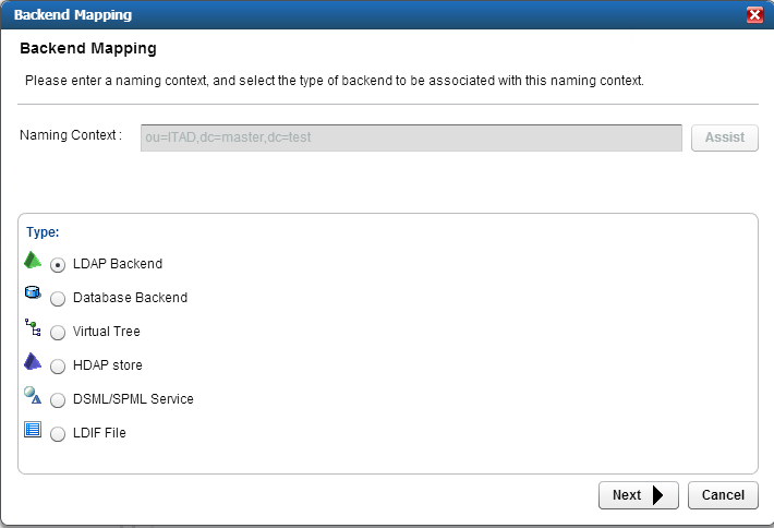
- Select one of the backend AD clusters that you configured earlier, and then click OK, as shown in Figure 8‑14.
Figure 8‑14 Adaptive Directory Configure LDAP Backend
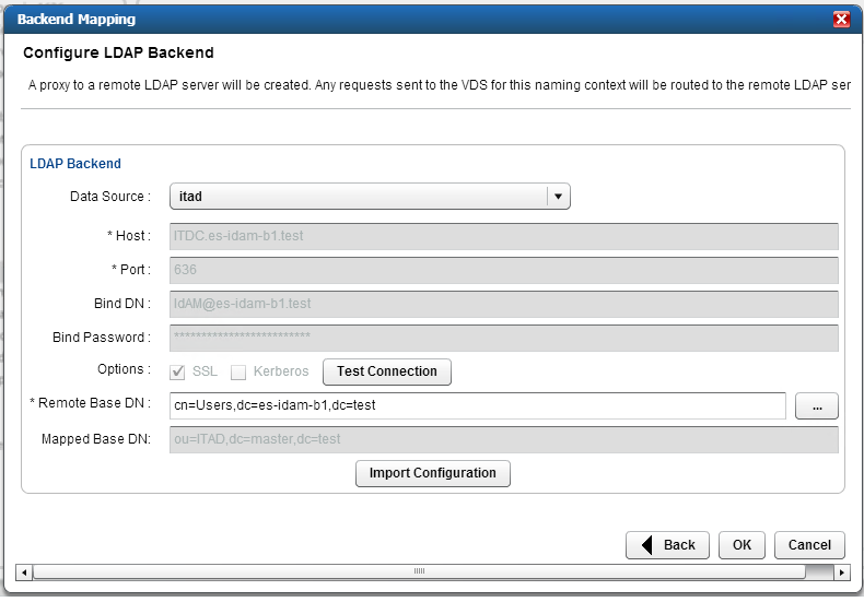
Repeat this procedure for all of your backend AD clusters (i.e., for the backend ADs on the IT, OT, and PACS networks).
By default, the Adaptive Directory server will return default AD attributes. If you need to configure it to return custom attributes, you can configure it by using the instructions provided in Section 8.4.
8.4. Custom Attribute Configuration
Custom attributes are required and are configured as follows:
- Click on Directory > Configuration. You will be presented with the screen shown in Figure 8‑15. Expand the virtual directory that you are working with, and then select the backend mapping to the AD to which you want to make changes. Click Attributes > Add.
Figure 8‑15 Adaptive Directory Addition Attributes
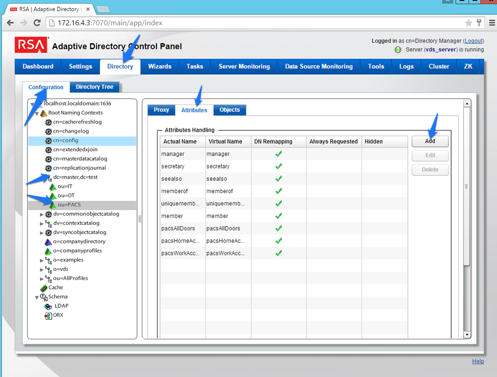
- Find the attribute that you would like to add in the top drop-down list (Name), and then enter a Virtual Name (it can be the same as, or different from, the Name) for the attribute that you want Adaptive Directory to return (Figure 8‑16). Select DN Remapping, and then click OK.
Figure 8‑16 Adaptive Directory Add/Edit Main Attribute
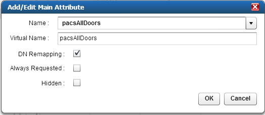
- Add the distinguishedName attribute to each backend, as shown in Figure 8‑17.
Figure 8‑17 Adaptive Directory Add Attribute
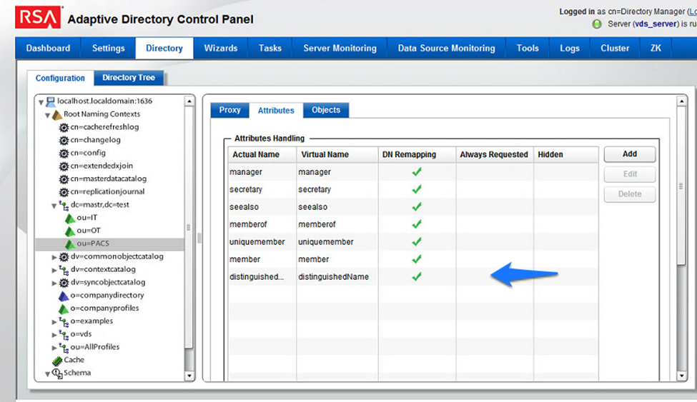
Repeat this procedure for any additional custom attributes that are required and for any additional AD backends to which you may need to add attributes.
Your Adaptive Directory virtual directory is now complete and can be accessed from RSA IMG / Aveksa or from any other application that can access LDAP directories.
You can address this virtual directory by configuring the connecting application with the IP address or DNS name of the Adaptive Directory server and by using Port 2389. For the base DN, you would use the name of your virtual directory—in the above example, dc=master,dc=test and the relevant OU (backend AD cluster) that you want to access. You would use the same username (cn=Directory Manager) and password that you use to log into the application.
For example, Figure 8‑18 and Figure 8‑19 show the connection information from RSA IMG to Adaptive Directory.
Figure 8‑18 Adaptive Directory Edit Collector
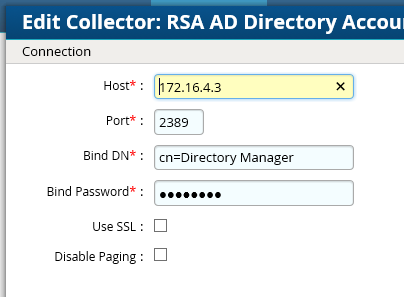
Figure 8‑19 Adaptive Directory Search Configuration for Accounts
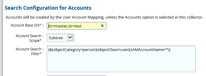
8.5. RSA Adaptive Directory Optimization and Tuning
8.5.1. Disable Referral Chasing
By default, RSA Adaptive Directory will attempt to chase referrals that have been configured in the underlying LDAP server. If you do not want RSA Adaptive Directory to chase referrals when searching the underlying LDAP server, you should check the Disable Referral Chasing option when you define the LDAP data source. Chasing referrals can affect the overall performance of RSA Adaptive Directory because, if the referral server is not responding (or is responding slowly), RSA Adaptive Directory could take a long time to respond to the client. For example, in the case of RSA Adaptive Directory querying an underlying Active Directory (with a base DN starting at the root of Active Directory), you may get entries like the following returned:
ldaps://ForestDnsZones.na.radiantlogic.com:636…
ldaps://DomainDnsZones.na.radiantlogic.com:636…
RSA Adaptive Directory will attempt to “chase” these referrals, which can result in an extreme degradation in response times. Therefore, it is recommended that you disable referral chasing if you need RSA Adaptive Directory to connect to Active Directory starting at the root of the Active Directory tree, or if you need to connect to any other directory where you do not care about following referrals.
8.5.2. Limit Attributes Requested from the LDAP Backend
Whenever RSA Adaptive Directory queries a backend LDAP, the default behavior is to ask for all attributes (although only the attributes requested in the query will be returned to the client). This default behavior of RSA Adaptive Directory is for the following reasons:
- Joins have been configured, and the filter in the search request involves attributes from both the primary and secondary sources (i.e., the query filter contains conditions on both primary and secondary objects).
- Interception scripts may involve logic that is based on attributes from the backend, and therefore require these attributes. These attributes may not be specifically requested or searched for by the client. However, RSA Adaptive Directory must retrieve these attributes from the backend for the script logic to be valid.
- Access Control List (ACL) checking: You can set up ACLs based on attributes/values of an entry (e.g., mystatus=hidden); RSA Adaptive Directory may need the whole entry to check the authorization.
- For entry caching, the entire entry needs to be in the entry cache.
If your virtual view does not require all attributes to be requested for any of the conditions mentioned above, you can enable the option to limit the attributes that are requested, for better performance. If this option is enabled, RSA Adaptive Directory will query the backend server only for attributes requested from the client, in addition to the attributes that are set as Always Requested on the Attributes tab.
8.5.3. Process Joins and Computed Attributes Only When Necessary
The default behavior of RSA Adaptive Directory is to process associated joins and to build computed attributes whenever a virtual object is reached from a query, regardless of whether the requested attributes come from a secondary source or a computation. If you enable the option to process joins and computed attributes only when necessary, RSA Adaptive Directory will not perform joins or computations when a client requests or searches for attributes from a primary object only. If a client requests or searches for attributes from secondary objects or computed attributes, RSA Adaptive Directory will process the join(s) and computations accordingly. Use caution when enabling this option, if you have interception scripts defined on these objects, or if access controls based on filters are being used (both of which may require other attributes returned from secondary sources or from computations, regardless of whether or not the client requested or searched for them).
8.5.4. Use the Client Sizelimit Value to Query the Backend
Whenever Adaptive Directory queries a backend LDAP, the default behavior is to ask for all entries (sizelimit=0), even if the client to Adaptive Directory indicates a size limit. This is the default behavior because the entries that are returned by the backend are possible candidates, but may not be retained for the final result that is sent to the client. For example, if an ACL has been defined in Adaptive Directory, not all entries from the backend may be authorized for the user (who is connected to Adaptive Directory) to access. As another example, when joins or interception scripts are involved with the virtual view, they may also alter the entries that match the client’s search. To limit the number of entries from the backend, the recommended approach is to use paging. If the backend supports paging, Adaptive Directory will not get all of the results at once; rather, it will get only one page at a time (the page size is indicated in the configuration). In this case, if Adaptive Directory has returned, to the client, the size limit that is required, Adaptive Directory will not go to the next page.
If your virtual view does not involve any of the conditions mentioned above (joins, interceptions, ACL), and if using paging between Adaptive Directory and the backend is not possible, you can enable the Client Sizelimit value option to limit the number of entries requested from the backend. If this option is enabled, Adaptive Directory will use the size limit specified by the client, instead of using sizelimit=0, when querying the backend.
9. Enterprise Guardian: AlertEnterprise
AlertEnterprise Enterprise Guardian (Guardian) is installed on the IdAM network, in a VM running the Windows Server 2012 R2 OS. Guardian is used to control privileged user access to the components located on the network OT systems. Guardian collects user authorization information from the AD located within the OT network. There are three parts to the Guardian How-To guide, each of which is provided in the sections below. Section 9.2 provides information on the general product installation and set-up. Section 9.3 provides information on the Guardian configuration, as configured in the RSA build. Section 9.4 provides information on the AlertEnterprise configuration, as configured in the CA build.
9.1. Security Characteristics
Cybersecurity Framework Categories: PR.AC-1: Identities and credentials are managed for authorized devices and users.
NIST SP 800-53 Revision 4 Security Controls: AC-2, IA Family
9.2. Installation on Tomcat and Windows
This section describes the detailed procedure of installing AlertEnterprise products on Tomcat on a Windows platform. It lists the hardware and software prerequisites as well as the steps to install and use the AlertEnterprise suite of applications.
When copying text from this guide, it is recommended that you first paste text to a Notepad file and then copy it from there to use it for running scripts. You should use the “Notepad++” application for this purpose.
9.2.1. Installation Prerequisites
The AlertEnterprise Suite is delivered as a Web Application Archive (WAR) file that needs to be deployed on the client’s application server. Before you actually start deploying on your application server, you must check for the prerequisites. Refer to the AlertEnterprise Systems Requirements document included in the installation package.
9.2.2. Pre-Installation Verification
Before you start installing the AlertEnterprise product, verify the proper functioning of the underlying software systems:
- Your system meets all of the software and hardware prerequisites as described in the Systems Requirement Specification document.
- A compatible version of Java Runtime Environment (JRE) is installed and working on the system.
- A compatible version of the web server is installed and running.
- A compatible version of the database server is installed and running.
- A supported internet browser (e.g., Microsoft Internet Explorer) is working properly.
Zip extracting software is required. You can download WinZip from http://www.winzip.com/win/en/prod_down.html.
9.2.3. Installing Mandatory Software Applications
Before deploying the AlertEnterprise application, install JRE and a web application server (e.g., Tomcat). You must also install the latest version of Adobe Flash Player to enable the internet browser that you will be using to access the AlertEnterprise application.
9.2.3.1. Installing JRE
To install JRE, follow the steps below:
- Download the application-server-compatible JRE.
- Double-click the setup launcher to start the installation process.
Setting Java Home
Make sure that the
JAVA_HOMEvariable is set to the folder where Java is installed, and that%JAVA_HOME%/binis in the system’s path.Open the Command Prompt in Administrator Mode (right-click > Run As Administrator), and then issue the following command:
Set
JAVA_HOME=<PATH OF JDK/JRE>Where, <PATH OF JDK/JRE> is the path where Java is installed (e.g.,
C:\Program Files\Java\JDK1.6)Set PATH:
PATH= C:\Program Files\Java\JDK1.6.0-21\bin;%PATH%Check
JAVA_HOMEandPATHEcho %JAVA_HOME%Echo %PATH%Checking JAVA Version: Java –version
9.2.3.2. Running ActiveMQ as Windows Service
After extracting the folder, the folder name appears as “apache-activemq” at the specified location.
- Go to the folder apache-activemq, and move to bin/win32 in Windows Explorer. Right-click on the InstallService.bat file, and select Run as Administrator.
- Once the above batch file gets executed, verify that the ActiveMQ is added as a Windows Service.
- Go to the Run command, and enter
services.msc. The Services (Local) window appears, as shown in Figure 9‑1.
Figure 9‑1 Adaptive Directory Search Configuration for Accounts
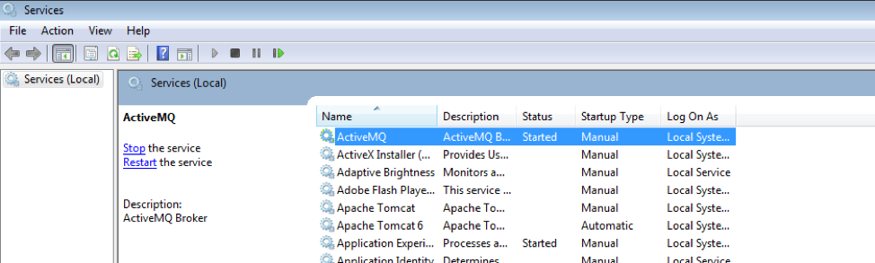
The Apache ActiveMQ service has an administrative console. To check if the service is running correctly, you simply need to connect to the admin console:
URL: <IP address of the server where Active MQ is installed>:8161/admin
Perform the following if ActiveMQ is on a server other than the AlertEnterprise server:
- Search for the URL that starts with “TCP ://<IP Address>:61616” in activemq.log, located in the Apache ActiveMQ home-directory/data folder (Figure 9‑2).
Figure 9‑2 Guardian ActiveMQ Home/Data Directory
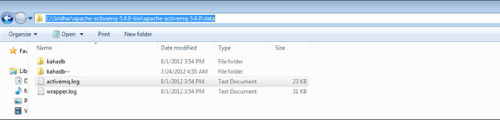
- Copy the URL, and update the context.xml file in the <Tomcat Home>/conf and appContextDB.properties file located in <Tomcat Home/webapps/AlertEnterprise/WEB-INF/classes>.
9.2.3.3. Steps for Failure Case
If the system throws an error message while executing the bat file, or if the ActiveMQ Services screen does not appear, follow these steps:
Navigate to the folder <ActiveMQ home directory>\bin\win32.
Open the InstallService.bat file in a local text editor.
Modify the bottom part of the script to look like the following script. Note that your JAVA_HOME environment variable needs to already be set and also needs to be passed as a variable to the wrapper.
:conf
set WRAPPER_CONF="%ACTIVEMQ_HOME%\bin\win32\wrapper.conf"
set ACTIVEMQ_HOME="set.ACTIVEMQ_HOME=%ACTIVEMQ_HOME%"
set ACTIVEMQ_BASE="set.ACTIVEMQ_BASE=%ACTIVEMQ_BASE%"
set JAVA_HOME="set.JAVA_HOME=%JAVA_HOME%"
rem
rem Install the Wrapper as an NT service.
Rem
:startup
"%ACTIVEMQ_HOME%\bin\win32\wrapper.exe" -i %_WRAPPER_CONF% %_ACTIVEMQ_HOME% %_ACTIVEMQ_BASE% %_JAVA_HOME%
if not errorlevel 1 goto :eof
pause
Open the <ActiveMQ home directory>\bin\win32\wrapper.conf in a local text editor, and make the following change:
Change this code:
# Java Application
wrapper.java.command=java
to this code:
# Java Application
wrapper.java.command=%JAVA_HOME%\bin\java.exe
After you have performed these steps, you should be able to run the InstallService.bat successfully.
To also use the UninstallService.bat file, open it, and then hard-code the path to the wrapper:
rem
rem Uninstall the Wrapper as an NT service.
rem
:startup
"%ACTIVEMQ_HOME%\bin\win32\wrapper.exe" -r %_WRAPPER_CONF%
if not error level 1 goto : eof
pause
After executing the InstallService.bat file, you can see the ActiveMQ in Services.
If the ActiveMQ server is not up, and the system throws the following error, perform the solution below.
| WARN | tmpdir | org.eclipse.jetty.util.log | WrapperSimpleAppMainjava.io.IOException: The system cannot find the path specified
at java.io.WinNTFileSystem.create File Exclusively (Native Method)
at java.io.File.check And Create (File.java:1343)
at java.io.File.create Temp File (File.java:1431)
Solution:
You must manually create two folders: <ActiveMQ home directory>/work and <ActiveMQ home directory>/temp.
To check whether ActiveMQ is started, access the following link, as shown in Figure 9‑3: http://<Server IP Address>:8161/admin/
Figure 9‑3 Guardian ActiveMQ
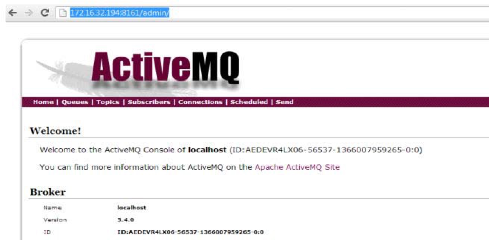
9.2.3.4. Installing Apache Tomcat
You must install hardware and OS versions specific to Apache Tomcat:
- Double-click the setup launcher to start the setup. It will start the installation process.
- Click Next to start the installation process.
- Click I Agree to accept the license terms. It displays the Choose Components screen.
- Select Custom as the install type, and uncheck the Examples option.
- Click Next to specify the destination folder for installation. We strongly recommend using the D:\AlertEnterprise\Tomcat location.
- Click Next to specify the configuration parameters.
- Enter the desired port in the Connector Port text area. The default port is 8080.
- Specify the User Name and Password in the respective fields.
- Click Next to select the path of the JRE installed on the system.
- Select the path of the JDK/JRE that you just installed (e.g., C:\Program Files\Java\jre1.6).
- Click Install to start the file copying process. Uncheck the Run Apache Tomcat and Show Readme options in the final dialog box.
- Click Finish to finish the installation.
9.2.3.5. Apache Tomcat Configuration
You need to specify the Tomcat configuration, as described in the following steps:
Click Start > Programs > Apache Tomcat > Configure Tomcat.
Click the Java tab in the Apache Tomcat Properties dialog box.
Enter the following settings:
- Initial memory pool:
1024 - Maximum memory pool:
1024 - Thread stack size:
300
Note: These settings may vary with the volume of random access memory (RAM) in the server.
- Initial memory pool:
Click Apply > OK to close the dialog box.
9.2.3.6. Configuring Database Server
You need to perform some configurations in the database server to install AlertEnterprise applications. You must perform these configurations through the database administrator login. The current version of AlertEnterprise products supports Oracle and Microsoft SQL Server databases. The NCCoE build also supports MySQL server database.
To configure the database server, follow these steps:
- Create a schema / system identifier (SID) per your naming convention in the database server. The steps to create a schema can be different with different database management systems. Refer to the administrators guide for the database management system installed at your landscape.
- Create a new user with full access to the created schema.
- Run the included SQL files,
AlertReport471.ddlorAlertReport471.sqland AlertQuartz.sql, on the new schema created. This step should be performed while nstalling the AlertEnterprise application for the first time.
9.2.3.7. Avoiding Case-Sensitivity Issues in Alert DB
To avoid case-sensitivity issues while using the search and sort functionalities in the AlertEnterprise applications, enable a “Case Insensitiveness” search in the database. By default, it is set as case-sensitive.
Follow these steps to avoid case-sensitivity issues:
Create a trigger to support case insensitiveness.
/***********/
create or replace
trigger set_nls_onlogon
AFTER LOGON ON SCHEMA
DECLARE
BEGIN
EXECUTE IMMEDIATE 'ALTER SESSION SET NLS_SORT="BINARY_CI"';
EXECUTE IMMEDIATE 'ALTER SESSION SET NLS_COMP="LINGUISTIC"';
END set_nls_onlogon;
/************/
Restart the AlertEnterprise Application server.
The effect may not be visible in some client tools, such as SQL Developer. To see the effect in the SQL Developer tool, follow these steps:
Open SQL Developer, and click Tools > Preferences.
Click Database > NLS, and perform the following actions:
- Set the Sort option to BINARY_CI.
- Set the Comparison option to LINGUISTIC.
9.2.3.8. Enabling Support for International Characters
Storage of character data is controlled by a character-set setting at the database level. It is recommended to have the following database settings to support international characters:
For Oracle:
NLS_CHARACTERSET = AL32UTF8
NLS_NCHAR_CHARACTERSET = AL16UTF16
For SQL Server:
Server Collation =SQL_Latin1_General_CP1_CI_AS
9.2.4. Deploying the Application
After you have successfully configured the database, proceed to deploy the AlertEnterprise product on your web application server. The following deployment steps are required for the Tomcat 6.0 version:
Use the Windows service control panel to stop the Tomcat server service if it is already running. Click Start > Run, type services.msc, and then click OK. Select Apache Tomcat, and click the Stop Service icon to stop the service.
Copy the
AlertEnterprise.war,AccessMap.war(if you have an AlertInsight license), andAlertEnterpriseHelp.war, andjasperserver-pro.warfiles to the<Tomcat installation folder>\webapps\path.You need to copy password management WAR file
AIPM.warto<Tomcat installation folder>/webappsif you have a license for the Password Management application.Create a new folder
AlertCommonLibandAlertExternalLibunder the<Tomcat Installation Folder>.Extract
AlertCommonLib.zipunder theAlertCommonLibfolder. You will see many new files in this folder.Edit the
<Tomcat Installation Folder>\conf\catalina.propertiesby using any editor, and append the following to thecommon.loader, as described below:common.loader=${catalina.base}/lib,${catalina.base}/lib/*.jar,${catalina.home}/lib,${catalina.home}/lib/*.jar,${catalina.home}/AlertCommonLib/*.jar,${catalina.home}/AlertExternalLib/*.jarSave the file, and close the editor.
Add a database connection. Add a new <resource> entry, as shown below, with the name “jdbc/alntdb” in
<Tomcat installation folder>\conf\context.xml. Replace the code in <> with relevant information.
For MySQL Server:
<Resource
description="DB Connection"
name="jdbc/alntdb" auth="Container"
type="com.mchange.v2.c3p0.ComboPooledDataSource"
factory="org.apache.naming.factory.BeanFactory"
user="username"
password="password"
jdbcUrl="jdbc:mysql://<IP of DB Server>:3306/<DB Instance Name>"
driverClass="com.mysql.jdbc.Driver"
maxPoolSize="100" minPoolSize="5" acquireIncrement="5"
numHelperThreads="20" maxIdleTime="600" maxIdleTimeExcessConnections="300"
debugUnreturnedConnectionStackTraces="true" unreturnedConnectionTimeout="900"
For repository setting in the same context.xml, add the following entry:
<ResourceLink name="AlertEnterpriseRepo" global="AlertEnterpriseRepo" type="javax.jcr.Repository" />
For ActiveMQ settings in same context.xml, add the following entry:
<Resource name="jms/connectionFactory"
        auth="Container"
        type="org.apache.activemq.ActiveMQConnectionFactory"
        description="JMS Connection Factory"
        factory="org.apache.activemq.jndi.JNDIReferenceFactory"
        brokerURL="tcp://localhost:61616"
        brokerName="LocalActiveMQBroker"
        useEmbeddedBroker="false"/>

<Resource name="jms/requestSubmissionQueue"
    auth="Container"
    type="org.apache.activemq.command.ActiveMQQueue"
    description="JMS Queue requestSubmissionQueue"
    factory="org.apache.activemq.jndi.JNDIReferenceFactory"
    physicalName="requestSubmissionQueue"/>

<Resource name="jms/requestApprovalQueue"
    auth="Container"
    type="org.apache.activemq.command.ActiveMQQueue"
    description="JMS Queue requestApprovalQueue"
    factory="org.apache.activemq.jndi.JNDIReferenceFactory"
    physicalName="requestApprovalQueue"/>

<Resource name="jms/autoApprovalQueue"
    auth="Container"
    type="org.apache.activemq.command.ActiveMQQueue"
    description="JMS Queue autoApprovalQueue"
    factory="org.apache.activemq.jndi.JNDIReferenceFactory"
    physicalName="autoApprovalQueue"/>

<Resource name="jms/queue/taskSubmissionQueue"
        auth="Container"
        type="org.apache.activemq.command.ActiveMQQueue"
        description="JMS Queue taskSubmissionQueue"
        factory="org.apache.activemq.jndi.JNDIReferenceFactory"
        physicalName="taskSubmissionQueue"/>
        <Resource name="jms/queue/taskRejectionQueue"
        auth="Container"
        type="org.apache.activemq.command.ActiveMQQueue"
        description="JMS Queue taskRejectionQueue"
        factory="org.apache.activemq.jndi.JNDIReferenceFactory"
        physicalName="taskRejectionQueue"/>

<Resource name="jms/queue/projectCancelQueue"
        auth="Container"
        type="org.apache.activemq.command.ActiveMQQueue"
        description="JMS Queue projectCancelQueue"
        factory="org.apache.activemq.jndi.JNDIReferenceFactory"
        physicalName="projectCancelQueue"/>

<Resource name="jms/queue/projectCompleteQueue"
        auth="Container"
        type="org.apache.activemq.command.ActiveMQQueue"
        description="JMS Queue projectCompleteQueue"
        factory="org.apache.activemq.jndi.JNDIReferenceFactory"
        physicalName="projectCompleteQueue"/>

<Resource name="jms/eventRequestQueue"
        auth="Container"
        type="org.apache.activemq.command.ActiveMQQueue"
        description="JMS Queue eventRequestQueue"
        factory="org.apache.activemq.jndi.JNDIReferenceFactory"
        physicalName="eventRequestQueue"/>

<Resource auth="Container" description="my Queue" factory="org.apache.activemq.jndi.JNDIReferenceFactory" name="jms/reqQueue" physicalName="requestQueue" type="org.apache.activemq.command.ActiveMQQueue"/>

<Resource auth="Container" description="my Queue" factory="org.apache.activemq.jndi.JNDIReferenceFactory" name="jms/resQueue" physicalName="responseQueue" type="org.apache.activemq.command.ActiveMQQueue"/>
- Edit
<Tomcat installation folder>\conf\server.xml. Replace the code in <> with relevant information:
<GlobalNamingResources>
<! -- Editable user database that can also be used by
UserDatabaseRealm to authenticate users
->
<Resource auth="Container" configFile="/AlertEnterpriseRepo/repository.xml"
description="AlertEnterprise Repository" factory="com.alnt.repository.jndi.JackrabbitRepositoryFactory"
homeDir="/AlertEnterpriseRepo" name="AlertEnterpriseRepo" type="javax.jcr.Repository"/>

<Resource auth="Container" description="Rule Engine Service" factory="com.sae.ruleengine.jndi.RuleEngineFactory"
name="Sedna" password="MANAGER" type="com.sae.ruleEngine.RuleEngine" username="SYSTEM"/>
<Resource name="UserDatabase" auth="Container"
type="org.apache.catalina.UserDatabase"
description="User database that can be updated and saved"
factory="org.apache.catalina.users.MemoryUserDatabaseFactory"
pathname="conf/tomcat-users.xml"/>
</GlobalNamingResources>
- Open the <Webserver installation folder>\bin location, and double-click tomcat5w.exe. Click the Java tab, and, under Java options, add the following lines of code at the end:
 -XX:PermSize=512m
 -XX:MaxPermSize=512m
 -Xms1024m
 -Xmx1024m
 -Djs.license.directory=C:\AlertApplication\Tomcat 6.0\webapps\jasperserver-pro
 -Dcom.alnt.fabric.loadInitData=force
 -Dalert.db.update=update


Note: These settings may vary with the volume of RAM in the server.
Start the Tomcat server.
Start the AlertEnterprise application by using the address, which is of the form http://<Server IP Address>:8080/AlertEnterprise.
Note: The name and contents of the init script will vary depending on the database management system of the organization. The default port on local host is 8080. If you want to change it, then change it in the sever.xml.
Log onto the application by using admin credentials. You should be able to view the home screen of the application.
9.3. AlertEnterprise Application Configurations for the RSA Build
9.3.1. System Type Import of DB Connector
- Log into Application.
- Go to Setup > Manual Configuration > Import/Export.
- Check System Types, and click on Import.
- Select the CSV files, which are in the software build package under the connector \ALNTDbconnector\InitDataFiles folder.
- After selecting all of the files, click the Upload button.
- Refresh the page until it shows as a success or failure.
- Restart the server if required.
9.3.2. System Type Parameters of DB Connector
Log into Application.
Go to Setup > Manual Configuration > Systems > System Types.
Search for the connector named “DBConnector,” and click the Modify button.
Click Next.
Add the following attributes, one by one, and then click the ADD button.
For the attributes, the Name and Label fields can be any user-friendly name, as shown in Table 9‑1. If the Name and Label fields already exist, do not create a duplicate.
Table 9‑1 Attributes
| Name | Label |
|---|---|
| jndiName | Jndi Name |
| DATE_TIME_FORMAT | Date and Time Format |
| DATE_TIME | Date Format |
| passwordColumnName | Passwrd Column Name |
| userIdColumnName | UserId Column Name |
| EXTERNAL_USER_ID_ATTRIBUTE | External UserId Attribute |
| MODIFIED_ENTITLEMENTS | Fetch User Entitlement based on last modified date(not by user) |
| GET_ALL_USERS0 | GET_ALL_USERS0 |
| GET_INCREMENTAL_USERS0 | GET_INCREMENTAL_USERS0 |
| CREATE_USER0 | Create CardHolder Query |
| UPDATE_USER0 | Update CardHolder Query |
| LOCK_USER0 | Lock CardHolder Query |
| UNLOCK_USER0 | Unlock Card Holder Query |
| DELIMIT_USER0 | Change CardHolder Validity Query |
| USER_PROVISIONED0 | Check Card Holder Provisioned Query |
| ADD_ROLES0 | Assign Roles to Card Holder Query |
| DEPROVE_ROLES0 | Remove Roles From Card Holder Query |
| GET_GENERATED_USERID0 | Retrieve User Id Query |
| driverName | driverName |
| url | URL |
| username | userName |
| Password | password |
| CREATE_USER1 | CREATE_USER1 |
| LOCK_USER1 | LOCK_USER1 |
Figure 9‑4 Guardian DB Connector Attributes
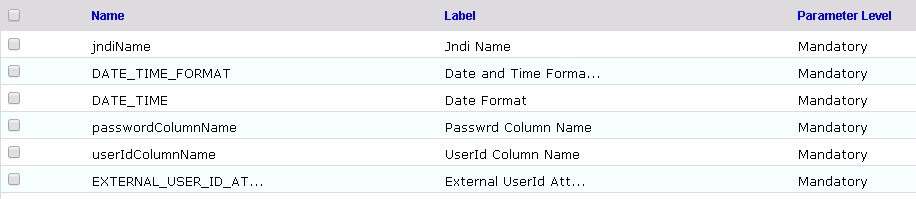
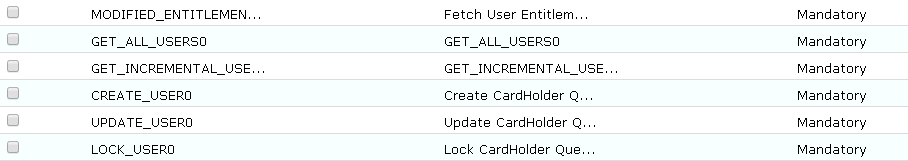
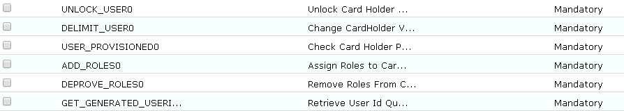
CONFIGURATION: Create “PACS AD” System
Setup > Manual Configuration > Systems > System.
Click New to create a new system.
Definition…Enter the following:
- System Type: LDAP from the drop-down
- Connector Name:
PACS AD - Connector Description:
PACS AD - Connector Long Description:
PACS AD - Connector Type:
LDAP(default)
- Click Next.
- Parameters: Enter the parameters listed in Table 9‑2.
Table 9‑2 Guardian PACS AD Parameters
| System Parameter Name | System Parameter Value |
|---|---|
| bindPass | **************** (Password for Dod_Admin User)o60ypIUQT3IOqHmbuRWeuw== |
| useSSL | FALSE |
| baseDns | DC=pacs-es-idam-b1,DC=test |
| groupBaseDn | DC=pacs-es-idam-b1,DC=test |
| reconBaseDN | |
| getIncrementGrpChanges | FALSE |
| wsdlURL | |
| wsUserName | |
| wsPwd | |
| rootLevelDomain | |
| cookieLocation | |
| adUserName | |
| SYS_CON_ATTR_POST_CREATE_SCRIPT | |
| SYS_CON_ATTR_POST_CREATE_SCRIPT_PARAMS | |
| objectClass | User |
| Skipprovisioning | Yes |
| lastModifiedColumnRole | whenChanged |
| lastModifiedColumn | whenChanged |
| Host | 172.16.7.2 |
| Port | 389 |
| bindDn | CN= DoD_Admin,AlertEnterprise, CN=Users,DC=pacs-es-idam-b1,DC=test |
Click Next.
Attributes: Enter the following:
- Application: Alert Access
- Check the following boxes: Provisioning, Role Management, Offline System.
- Leave the Connector Category as Production.
- Time Zone: Greenwich Mean Time from the drop-down
Click Next, and then click Save.
CONFIGURATION: Create “Identity DB” System
This connector is required for internal purposes. Ignore this step (7) if the Identity DB connector is already setup.
Steps to create this connector:
Setup > Manual Configuration > Systems > System.
Click New to create a new system.
Definition…Enter the following:
- System Type: Database (JDBC J2EE) from the drop-down
- Connector Name:
IDENTITYDB - Connector Description:
IDENTITYDB - Connector Long Description:
IDENTITYDB - Connector Type: Database (JDBC J2EE) (default)
Click Next.
Parameters: Enter the parameters listed in Table 9‑3.
Table 9‑3 Guardian Identity DB Parameters
| System Parameter Name | System Parameter Value |
|---|---|
| driverName | Use default |
| url | Use default |
| username | Use default |
| Password | Use default |
| whereClause | Use default |
| jndiName | java:comp/env/jdbc/alntdb |
Click Next.
Attributes: Enter the following:
Application: All
- Check the following boxes: Provisioning, Certification, Identity Provider, Allow Modify Role, and Allow Time Change.
- Leave the Connector Category as Production.
- Time Zone: Eastern Daylight Time from the drop-down
- Click Next, and then click Save.
CONFIGURATION: Create “ACCESSIT PACS” System
This connector is required to integrate with RS2 PACS systems and to perform various provisioning operations.
Steps to create this connector:
Setup > Manual Configuration > Systems > System.
Click New to create a new system.
Definition…Enter the following:
- System Type: DBConnector from the drop-down
- Connector Name:
ACCESSIT PACS - Connector Description:
ACCESSIT PACS - Connector Long Description:
ACCESSIT PACS - Connector Type:
DBConnector(default)
Click Next.
Parameters: Enter the parameters listed in Table 9‑4.
Table 9‑4 Guardian ACCESSIT PACS DBConnector Parameters
| System Parameter Name | System Parameter Value |
|---|---|
| driverName | com.microsoft.sqlserver.jdbc.SQLServerDriver |
| URL | jdbc:sqlserver://<HOST_NAME>:<PORT>;databaseName=AIUniversal <HOST_NAME> should be replaced with the hostname of the RS2 PACS system l |
| Username | The value of the parameter is the name of the user that is used to log in and connect to RS2 PACS database |
| Password | The value of the parameter is the password of the user that is used to log in and connect to RS2 PACS database |
| Date and Time Format | MM/dd/yyyy HH:mm:ss |
| External UserId Attribute | CardholderID |
| Create CardHolder Query | INSERT INTO [AIUniversal].[dbo].[Cardholders]([CardholderID],[LastName],[FirstName],[Midd leInitial],[CompanyID],[Notes],[LastModified],[LastModifiedByUser],[DateCreat ed],[CreatedByUser],[MemberOfAllSites],[UserText1],[UserText2],[UserText3],[U serText4],[UserText5],[UserText6],[UserText7],[UserText8],[UserText9],[UserTe xt10],[UserText11],[UserText12],[UserText13],[UserText14],[UserText15],[UserT ext16],[UserText17],[UserText18],[UserText19],[UserText20],[Department],[User Date1],[UserDate2],[UserDate3],[UserDate4],[UserDate5],[UserNumeric1],[UserNu meric2],[UserNumeric3],[UserNumeric4],[UserNumeric5],[CardholderStatus],[Card holderActiveDate],[CardholderExpireDate]) VALUES (NEWID(),$LastName,$FirstName,$MiddleInitial,$CompanyID,$Notes,GetUTCDate(),’ alertent’,GetUTCDate(),’alertent’,‘1’,$UserText1,$UserText2,$UserText3,$UserT ext4,$UserText5,$UserText6,$UserText7,$UserText8,$UserText9,$UserText_10,$Use rText_11,$UserText_12,$UserText_13,$UserText_14,$UserText_15,$UserText_16,$Us erText_17,$UserText_18,$UserText_19,$UserText_20,$Department,$UserDate1,$User Date2,$UserDate3,$UserDate4,$UserDate5,$UserNumeric1,$UserNumeric2,$UserNumer ic3,$UserNumeric4,$UserNumeric5,‘1’,$CardholderActiveDate,$CardholderExpireDa te) |
| Update CardHolder Query | BEGIN IF NOT EXISTS (SELECT [CardNumber] FROM [AIUniversal].[dbo].[Cards] WHERE [CardNumber]=$CardNumber) BEGIN INSERT INTO [AIUniversal].[dbo].[Cards] ([CardID],[CardholderID],[CardNumber],[FacilityCode],[PINNumber],[PINExempt], [APBExempt],[UseExtendedAccessTimes],[CardStatus],[ActiveDate],[ExpireDate],[ UserLevel],[UseCustomReporting],[EventInfo],[Notes],[LastModified],[LastModif iedByUser],[DateCreated],[CreatedByUser],[IssueLevel],[DeactivateExempt],[Vac ationDate],[VacationDuration],[UseCount],[TempDeactivateStart],[TempDeactivat eEnd],[Classification],[IPLocksetUserType],[IPLocksetAccessMode],[IPLocksetCr edentialFormat],[IPLocksetAccessAlways],[RawPrimaryCredential],[LargeEncodedC ardID],[EmbossedNumber]) VALUES (NEWID(),$UserText1,$CardNumber,$FacilityCode,$PIN,‘0’,‘0’,‘0’,‘1’,NULL,NULL, ‘0’,‘0’,NULL,NULL,SYSDATETIME(),’alertent’,SYSDATETIME(),’alertent’,‘0’,‘0’,N ULL,‘0’,‘255’,NULL,NULL,’Active’,NULL,NULL,NULL,NULL,NULL,NULL,’‘) END END; |
| Lock CardHolder Query | update [dbo].[Cardholders] set CardholderStatus=‘0’ where CardholderID=$CardholderID |
| Unlock Card Holder Query | update [dbo].[Cardholders] set CardholderStatus=‘1’ where CardholderID=$CardholderID |
| Check Card Holder Provisioned Query | select CardholderID from [dbo].[Cardholders] where CardholderID =$CardholderID |
| Assign Roles to Card Holder Query | INSERT INTO [dbo].[CardholderAccessLevels] ( [CardholderAccessLevelID], [CardholderID], [AccessLevelID],[LastModified],[ActivateDate],[DeactivateDate]) VALUES ( NEWID(), $CardholderID,(select AccessLevelID from [dbo].[AccessLevels] where AccessLevelName=$ROLE_NAME),GetUTCDate(), NULL, NULL) |
| Remove Roles From Card Holder Query | delete from [dbo].[CardholderAccessLevels] where CardholderID=$CardholderID and AccessLevelID=(select AccessLevelID from [dbo].[AccessLevels] where AccessLevelName=$ROLE_NAME) |
| Retrieve User Id Query | select CardholderID from [dbo].[Cardholders] where UserText1=$UserText1 |
| CREATE_USER1 | BEGIN IF $CardNumber is null BEGIN update [dbo].[Cardholders] set CardholderStatus=‘1’ where UserText1=$UserText1 END ELSE BEGIN INSERT INTO [AIUniversal].[dbo].[Cards] ([CardID],[CardholderID],[CardNumber],[FacilityCode],[PINNumber],[PINExempt], [APBExempt],[UseExtendedAccessTimes],[CardStatus],[ActiveDate],[ExpireDate],[ UserLevel],[UseCustomReporting],[EventInfo],[Notes],[LastModified],[LastModif iedByUser],[DateCreated],[CreatedByUser],[IssueLevel],[DeactivateExempt],[Vac ationDate],[VacationDuration],[UseCount],[TempDeactivateStart],[TempDeactivat eEnd],[Classification],[IPLocksetUserType],[IPLocksetAccessMode],[IPLocksetCr edentialFormat],[IPLocksetAccessAlways],[RawPrimaryCredential],[LargeEncodedC ardID],[EmbossedNumber]) VALUES (NEWID(),(select CardholderID from [dbo].[Cardholders] where UserText1=$UserText1),$CardNumber,$FacilityCode,$PIN,‘0’,‘0’,‘0’,‘1’,NULL,NUL L,‘0’,‘0’,NULL,NULL,SYSDATETIME(),’alertent’,SYSDATETIME(),’alertent’,‘0’,‘0’ ,NULL,‘0’,‘255’,NULL,NULL,’Active’,NULL,NULL,NULL,NULL,NULL,NULL,’‘) END END; |
| LOCK_USER1 | update [AIUniversal].[dbo].[Cards] set CardStatus=‘0’,Classification=’InActive’ where [CardNumber]=$CardNumber |
Click Next.
Attributes: Enter the following:
Application: All
- Check the following boxes: Provisioning, Role Management, and Offline System.
- Leave the Connector Category as Production.
- Time Zone: Eastern Daylight Time from the drop-down
Click Next, and then click Save.
9.3.2.1. Create ACCESSIT PACS System Roles
Click the Roles menu, and click Create New Role.
On the popup window, select the option Create completely new role from Start.
Select the option Physical System from the System category drop-down list.
Enter ACCESSIT PACS under the System Name field, and then click the Search button.
From the search results, select the ACCESSIT PACS system, and then click Continue.
On the next page, provide details for the following fields, and then click Next Step.
- Role Name:
All Doors - Description:
All Doors - Alias:
All Doors - Active for Provisioning:
Yes - Provisioning Assigned:
Yes
- Role Name:
Click Next Step > Next Step > Next Step, and then click the Save button on the last page.
Repeat the above steps, and create the following roles:
Home Access Level
Work Order Access Level
Note: The above roles are created manually, but this is only one of the ways to create PACS system roles in the Alert application. The PACS system roles can also be imported from a flat file, or they can be directly fetched from the PACS system through a reconciliation process (Form customization > Attributes).
9.3.2.2. Create New Custom Form Attributes
- Setup > Manual Configuration > Form customization > Attributes.
- Click the New button.
- Create a new attribute called PacsAllDoors, based on the information provided in Table 9‑5.
Table 9‑5 New Custom Form Attributes
| Field Name | Field Value |
|---|---|
| Name | PacsAllDoors |
| Label | PacsAllDoors |
| Description | PacsAllDoors |
| Visible | Yes |
| Mandatory | No |
| Read Only | No |
| Field Type | TextField (Select this value from drop down) |
| USS Create Request | Yes(Select Checkbox) |
| USS User Information | No(Select Checkbox) |
| Approver View | No(Select Checkbox) |
| Provisioning | Yes(Select Checkbox) |
| Create Request Sequence | 10 |
| User Info Sequence | 10 |
| Approver Sequence | 10 |
| Group Name | Personnel Information (Select this value from drop down) |
- Click Save.
- Repeat Steps 1 through 4 to create the following custom form attributes (Table 9‑6 through Table 9‑9).
Table 9‑6 Create PacsHomeAccess Attribute
| Field Name | Field Value |
|---|---|
| Name | PacsHomeAccess |
| Label | PacsHomeAccess |
| Description | PacsHomeAccess |
| Visible | Yes |
| Mandatory | No |
| Read Only | No |
| Field Type | TextField (Select this value from drop down) |
| USS Create Request | Yes(Select CheckBox) |
| USS User Information | Yes(Select CheckBox) |
| Approver View | Yes(Select CheckBox) |
| Provisioning | Yes(Select CheckBox) |
| Create Request Sequence | 11 |
| User Info Sequence | 11 |
| Approver Sequence | 11 |
| Group Name | Personnel Information (Select this value from drop down) |
Table 9‑7 Create PacsWorkAccess Attribute
| Field Name | Field Value |
|---|---|
| Name | PacsWorkAccess |
| Label | PacsWorkAccess |
| Description | PacsWorkAccess |
| Visible | Yes |
| Mandatory | No |
| Read Only | No |
| Field Type | TextField (Select this value from drop down) |
| USS Create Request | Yes(Select CheckBox) |
| USS User Information | Yes(Select CheckBox) |
| Approver View | Yes(Select CheckBox) |
| Provisioning | Yes(Select CheckBox) |
| Create Request Sequence | 12 |
| User Info Sequence | 12 |
| Approver Sequence | 12 |
| Group Name | Personnel Information (Select this value from drop down) |
Table 9‑8 Create FacilityCode Attribute
| Field Name | Field Value |
|---|---|
| Name | FacilityCode |
| Label | Facility Code |
| Description | Facility Code |
| Visible | Yes |
| Mandatory | Yes |
| Read Only | No |
| Field Type | TextField (Select this value from drop down) |
| USS Create Request | No |
| USS User Information | No |
| Approver View | No |
| Provisioning | Yes(Select CheckBox) |
| Create Request Sequence | |
| User Info Sequence | |
| Approver Sequence | |
| Group Name | Personnel Information (Select this value from drop down) |
Table 9‑9 Create PIN Attribute
| Field Name | Field Value |
|---|---|
| Name | PIN |
| Label | PIN |
| Description | PIN |
| Visible | Yes |
| Mandatory | No |
| Read Only | No |
| Field Type | TextField (Select this value from drop down) |
| USS Create Request | Yes(Select CheckBox) |
| USS User Information | No(Select CheckBox) |
| Approver View | No(Select CheckBox) |
| Provisioning | Yes(Select CheckBox) |
| Create Request Sequence | 12 |
| User Info Sequence | |
| Approver Sequence | |
| Group Name | Personnel Information (Select this value from drop down) |
9.3.2.3. Modify statusLDAP Attribute
- Setup > Manual Configuration > Form customization > Attributes.
- Select the Status field from list of Attributes, and then click Modify.
- If statusLDAP is not present, create a new attribute for statusLDAP by following the steps mentioned in the section Create New Custom Form Attributes.
- Click the DropDown Values icon.
- On the popup window, click New, and provide 514 in the Name field, and 0 (zero) in the Label field (Figure 9‑5).
Figure 9‑5 Create DropDown Values
- Click Save to save the mapping.
- Similarly, enter the following values for the Name and Label fields (Figure 9‑6).
Figure 9‑6 DropDown Values
- Click Save > Save to save the configuration.
9.3.2.4. Identity & Access– Enable Identity
- Setup > Manual Configuration > Identity & Access > Enable Identity.
- Enable the following for the “Identity DB” system (Figure 9‑7).
Figure 9‑7 Guardian Identify Configuraton

9.3.3. Identity & Access– User Field Mapping
- Setup > Manual Configuration > Identity & Access > User Field Mapping.
- Select User = Identity (from the drop-down), and then click on Go.
- Click the Create New button.
- Select the Custom Field, Primary Key, Visible In List, and Is Searchable fields, based on Table 9‑10. Select the checkbox for each field that is identified with a “Yes” in Table 9‑10. For each field that is identified with a “No” in Table 9‑10, ensure that the checkbox is unchecked (cleared).
- Repeat Steps 1 through 4 for all fields in Table 9‑10. If a field already has the correct values, leave it as-is.
Table 9‑10 User Field Mapping
| Custom Field | Primary Key | Visible In List | Is Searchable |
|---|---|---|---|
| UserId | No | Yes | No |
| ValidFrom | No | Yes | No |
| ValidTo | No | Yes | No |
| FirstName | No | Yes | Yes |
| LastName | No | Yes | Yes |
| No | No | No | |
| Building | No | No | No |
| ManagerId | No | No | No |
| BadgeStatus | No | No | No |
| BadgeType | No | No | No |
| BadgeValidFrom | No | No | No |
| BadgeValidTo | No | No | No |
| Location | No | No | No |
| BadgeId | No | No | No |
| EmployeeType | No | No | No |
| Department | No | No | No |
| Password | No | No | No |
| Groups | No | No | No |
| ManagerName | No | No | No |
| ManagerLN | No | No | No |
| Manager | No | No | No |
| ManagerId | No | Yes | No |
| Status | No | No | No |
| Telephone | No | No | No |
| ImageUpload | No | No | No |
| Password_AD | No | No | No |
| PacsAllDoors | No | Yes | No |
| PacsHomeAccess | No | Yes | No |
| PacsWorkAccess | No | Yes | No |
9.3.3.1. Identity & Access > Recon Authoritative Fields
- Setup > Manual Configuration > Identity & Access > Recon Authoritative Fields (Figure 9‑8).
- Click New.
- Select PACS AD from the Systems drop-down, and select PacsAllDoors from the Authoritative Field drop-down.
- Click the Save button to save the mapping.
Figure 9‑8 Create Recon Authoritative Fields
- Repeat Steps 1 through 4 to configure mapping other fields, such as PacsWorksAccess and PacsHomeAccess, as listed in Figure 9‑9.
Figure 9‑9 Guardian Recon Authoritative Fields
9.3.3.2. Identity & Access > Request Categories
Setup > Manual Configuration > Identity & Access > Request Categories.
Select ChangeAccess Category name, and click Modify.
- On the Modify screen, make the following changes:
- In the Provisioning Actions section, un-select the Delimit User and Change Validity Dates checkboxes, if they are selected, and select the Change User option.
- Go to the Add Existing section, and select the system and Remove Role option from the Resources/Roles drop-down field.
Click Save to save the configuration.
Figure 9‑10 Create External Provisioning Attribute
- Repeat Steps 1 and 2 to configure the fields listed in Figure 9‑11.
Note: Field names are case-sensitive.
Figure 9‑11 Field Names
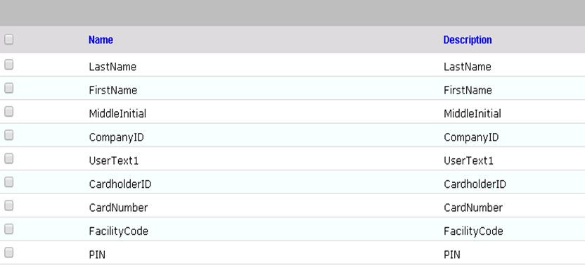
9.3.3.3. Identity & Access>Provisioning>Provisioning Mapping
- Setup > Manual Configuration > Identity & Access > Provisioning > Provisioning Mapping.
- Select ACCESSIT PACS, and click Configure.
- On the next screen, click the New button, and select UserText1 for the DB Connector Attribute Name (Figure 9‑12).
Figure 9‑12 Provisioning Mapping
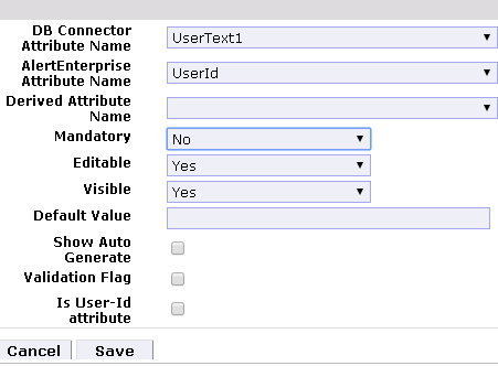
- Click Save to save the mapping.
- Repeat Steps 1 through 4 to configure the other fields shown in Figure 9‑13.
Figure 9‑13 Guardian DB Connector Attribute Mapping
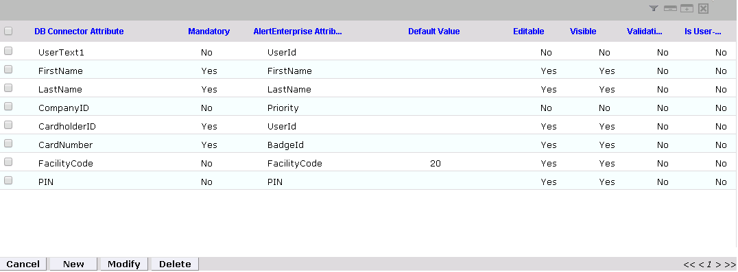
9.3.3.4. Policy Engine> Rules
- Setup > Manual Configuration > Policy Engine > Rules.
- Click the New button.
- On the next screen, provide the information shown in Figure 9‑14.
Figure 9‑14 Define Rules
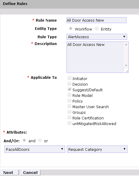
- Click the Next button.
- On the next screen, click New to define a new rule condition for the NewHire request category (Figure 9‑15).
Figure 9‑15 Define Condition
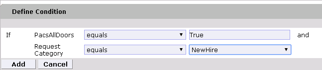
- Repeat Step 5 to define a new rule condition for the other request categories (Remove User Access and ChangeAccess), as shown in Figure 9‑16.
Figure 9‑16 Define Rule Conditions for Other Request Categories
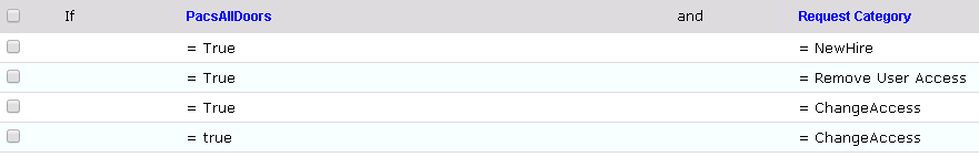
- Repeat Steps 1 through 6 to configure All Door Access New, Home Access Level New and WO Access Level New, as shown in Table 9‑11.
Table 9‑11 Rule Name Table
| Rule Name | Entity Type | Rule Type | Description | Applicable to | Attributes | Selection Value |
|---|---|---|---|---|---|---|
| All Door Access New | Workflow | AlertAccess | All Door Access New | Suggest/ Default | PacsALLDoors AND Request Category |
3 . True and ChangeAccess |
| Home Access Level New | Workflow | AlertAccess | Home Access Level New | Suggest/ Default | PacsHomeAccess AND Request Category |
|
| WO Access Level New | Workflow | AlertAccess | WO Access Level New | Suggest/ Default | PacsWorkAccess AND Request Category |
|
9.3.3.5. Policy Engine > Rule Action Handler
- Setup > Manual Configuration > Policy Engine > Rule Action Handler.
- Click New, and create the Action Handlers listed in Table 9‑12.
Table 9‑12 Guardian Policy Engine Rule Action Handler
| Action Handler Name | Workflow | Task Type | Value | Priority | Update Identity Info.? | Evaluate Enterprise Role? |
|---|---|---|---|---|---|---|
| Recon New Hire | AlertAccess | Recon Create Request | New Hire | 0 | Yes | No |
| Recon Terminate Handler | AlertAccess | Recon Create Request | Terminate | 0 | Yes | No |
| Recon Error Handler | AlertAccess | Recon Exception Record Task | 0 | |||
| ReconChangeHandler | AlertAccess | Recon Create Request | Change Access | 0 | Yes | No |
9.3.3.6. Policy Engine > Suggest/Default Access
- Setup > Manual Configuration > Policy Engine > Suggest/Default Access
- Click New, and enter the following information to create the All Door Access criteria (Figure 9‑17).
Figure 9‑17 Suggest/Default Access
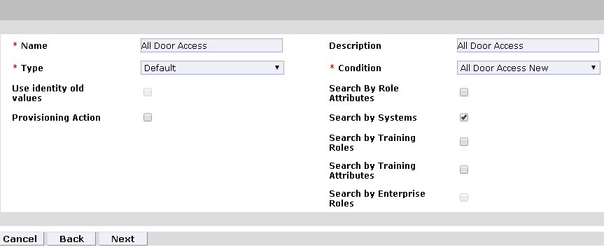
- On the next screen, click the Enter button.
- On the next screen, enter
ACCESSIT PACSin the System Name field, and then click the Search button. - The system will appear in the Search Results pane. Click the Add link under the Action column to add the system to the Selected Systems section.
- Click the Next button
- On the next screen, enter
ALL DOORSin the Role Name field, and then click the Search button. - The Role will appear in the Search Results pane. Click the Add link under the Action column to add the role to the Selected Roles section.
- Click the Save button to save the configuration.
- Repeat Steps 1 through 9 to configure other criterias for Home Access Level, WO Access Level, and NewHireDefaultSystems, as listed in Table 9‑13.
Table 9‑13 Manual Configuration Policy Engine Suggest/Default Access
| Name | Type | Condition | Search by System | Selected System | Selected Role |
|---|---|---|---|---|---|
| All Door Access | Default | All Door Access NEW | Yes (select checkbox) |
ACCESSIT PACS | ALL DOORS |
| Home Access Level | Default | Work Access Level New | Yes (select checkbox) |
ACCESSIT PACS | Home Access Level |
| WO Access Level | Default | Home Access Level New | Yes (select checkbox) |
ACCESSIT PACS | WO Access Level |
| NewHireDefaultSystems | Default | NewHireDefaultRule | Yes (select checkbox) |
ACCESSIT PACS |
- Select all existing Suggest Default Access criteria, other than the ones listed in Table 9‑13, and click Delete to delete them.
9.3.3.7. Policy Engine > Rule Action Handler
- Setup > Manual Configuration > Policy Engine > Rule Action Handler.
- In the Action Handlers List page, select ReconChangeHandler, and Click Modify.
- On the next screen, select Recon Create Request for the Task type drop‑down field, and click Update Task.
- On the popup window, click the Value drop‑down field, and select ChangeAccess (Figure 9‑18).
Figure 9‑18 Modify Task
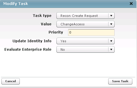
- Click Save Task, and then Click the Save.
9.3.3.8. Policy Engine > Policy Designer
Setup > Manual Configuration > Policy Engine > Policy Designer.
Select New to create a new policy designer as follows (Figure 9‑19):
- Name:
User Policy New - Rule type: AlertAccess
- Description:
User Policy New
- Name:
Figure 9‑19 Policy Designer
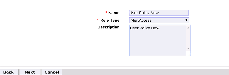
- Click Next.
- Drag the elements from the toolbar section that is available at the top of the page, place the elements onto the layout page, and then connect each node as mentioned in Figure 9‑20.
Figure 9‑20 Toolbar Section
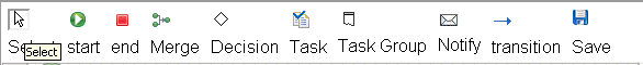
 represents the start button
 represents the end button
 represents a decision
 represents a transition
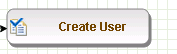 represents a task
Guidelines to configure the policy:
- To place an element/node on the layout page, drag it from the toolbar, and then place it on the layout page.
- To connect two nodes, select the transition icon from the toolbar, and then mouse over to the first node and connect it to the other node in the same direction specified in Figure 9‑21.
Figure 9‑21 Guardian User Policy
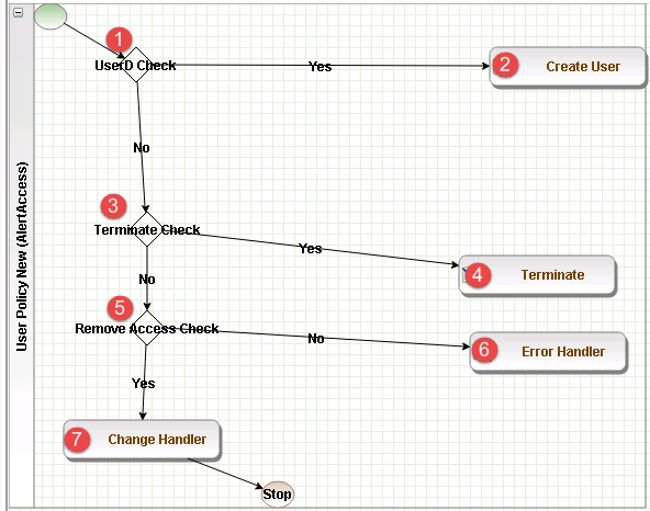
- Click on the Step 1 decision box, and it will open a popup window with some fields (Figure 9‑22).
- Enter
$masterUser[UserId].size='0'in the Condition field, and then press Enter.
Figure 9‑22 Tasks
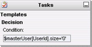
- Similarly, click on the other steps (2 through 7), and configure the data based on Table 9‑14. For decision nodes, provide the Condition value; for task nodes, like Create User, Terminate, Change Handler, and Error Handler, provide the Is Task Handler and Task Handler fields.
Table 9‑14 Guardian User Policy
| Step | Name | Type | Condition | Is Task Handler | Task Handler | Update Query |
|---|---|---|---|---|---|---|
| 1 | User ID Check | Decision | $masterUser[UserId] .size=‘0’ | |||
| 2 | Create User | Task Handler | Yes | Recon New Hire | ||
| 3 | Terminate Check | Decision | $checkStatus[status LDAP,512;546;66048; 544;UserStatus,Acti ve,514;66050;InActi ve].action=’LOCK’ | |||
| 4 | Terminate | Task Handler | Yes | Recon Terminate Handler | ||
| 5 | Remove Access Check | Decision | $checkAuthFields[]. status=’Yes’ | |||
| 6 | Error Handler | Task Handler | Yes | Recon Error Handler | ||
| 7 | Change Handler | Task Handler | Yes | Recon Change Handler |
9.3.3.9. Job Scheduler > Triggers Field Map
Setup > Manual Configuration > Job Scheduler > Triggers Field Map.
Click New.
Enter the following fields:
- Group Name:
PACSAD Field Map - Description:
PACSAD Field Mapping - Select Type:
Reconciliation
- Group Name:
After creating a field map, select the newly created map, and then select Configure.
Click New, and create a mapping according to Figure 9‑23.
Figure 9‑23 Guardian Job Scheduler Triggers Field Map
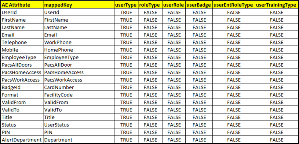
9.3.3.10. Job Scheduler > Triggers
- Setup > Manual Configuration > Job Scheduler > Triggers.
- Click New, and create the
PACSAD Trigger(Table 9‑15).
Table 9‑15 Guardian Job Scheduler Triggers
| Name | PACSAD Trigger |
|---|---|
| Description | PACSAD Trigger |
| Type | Reconciliation |
| Batch Size | 100 |
| Number of Attempts | 3 |
| Policy Designer for Users/Roles | User policy New |
| System: Reconciliation From | PACS AD |
| Reconciliation System | PACS AD |
| Field Mapping Group | PACSAD Field Map |
| User Type | True |
| User Role | True |
9.3.3.11. Job Scheduler > Scheduler
Setup > Manual Configuration > Job Scheduler > Scheduler.
Click New, and enter the following fields, as shown in Figure 9‑24.
- Job Type: Reconciliation Job
- Job Name: <Job Name>
- Select the Global checkbox
- Reconciliation for: Users
- Reconciliation Type: Incremental Reconciliation
- Reconciliation Triggers: PACSAD Trigger
- Select the schedule as Immediate, Once, Periodically, or Advance. For Periodically, specify the Start At, End At, and Rerun every (duration of job frequency, which should be no less than every 2 minutes).
Figure 9‑24 Guardian Reconciliation Job
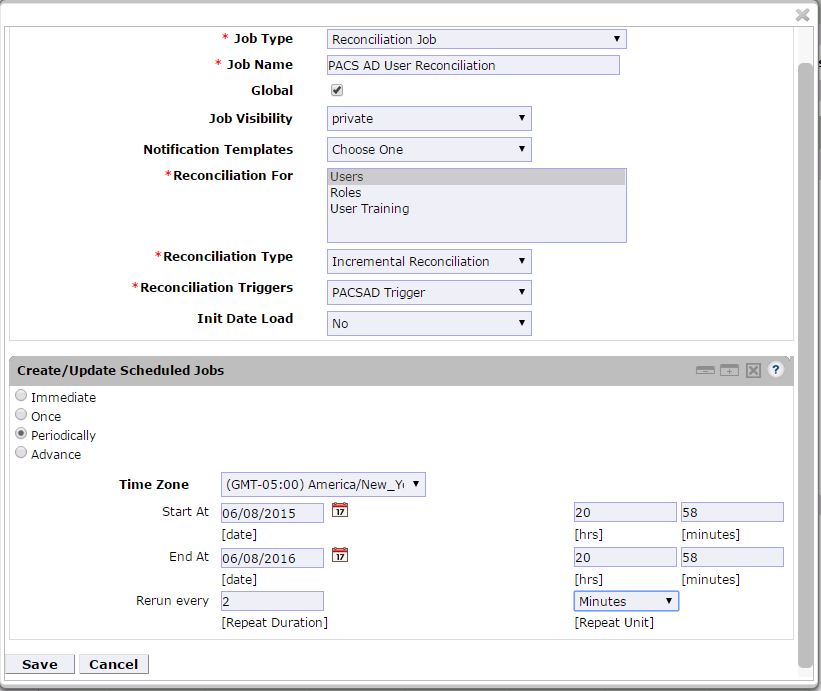
- Click Save.
9.4. AlertEnterprise Enterprise Guardian Configuration for the CA Build
9.4.1. System Type Import of DB Connector
- Log into the application.
- Go to Setup > Manual Configuration > Import/Export.
- Check System Types, and then click Import.
- Select the CSV files, which are in software build package under the Connector \ALNTDbconnector\InitDataFiles folder.
- After selecting all of the files, click the Upload button.
- Refresh the page until it shows as a success or failure.
- Restart the server if required.
9.4.2. System Type Parameters of DB Connector
- Log into the application.
- Go to Setup > Manual Configuration > Systems > System Types.
- Search for the connector named “DBConnector,” and then click the Modify button.
- Click Next.
- Add the following attributes, one by one, and then click the ADD button.
For the attributes, the Name and Label fields can be any user-friendly names, as shown in Table 9‑16. If the Name and Label fields already exist, do not create a duplicate.
Table 9‑16 DB Connector Name and Label Fields
| Name | Label |
|---|---|
| jndiName | Jndi Name |
| DATE_TIME_FORMAT | Date and Time Format |
| DATE_TIME | Date Format |
| passwordColumnName | Passwrd Column Name |
| userIdColumnName | UserId Column Name |
| EXTERNAL_USER_ID_ATTRIBUTE | External UserId Attribute |
| MODIFIED_ENTITLEMENTS | Fetch User Entitlement based on last modified date(not by user) |
| GET_ALL_USERS0 | GET_ALL_USERS0 |
| GET_INCREMENTAL_USERS0 | GET_INCREMENTAL_USERS0 |
| CREATE_USER0 | Create CardHolder Query |
| UPDATE_USER0 | Update CardHolder Query |
| LOCK_USER0 | Lock CardHolder Query |
| UNLOCK_USER0 | Unlock Card Holder Query |
| DELIMIT_USER0 | Change CardHolder Validity Query |
| USER_PROVISIONED0 | Check Card Holder Provisioned Query |
| ADD_ROLES0 | Assign Roles to Card Holder Query |
| DEPROVE_ROLES0 | Remove Roles From Card Holder Query |
| GET_GENERATED_USERID0 | Retrieve User Id Query |
| driverName | driverName |
| url | URL |
| userName | userName |
| password | password |
| CREATE_USER1 | CREATE_USER1 |
| LOCK_USER1 | LOCK_USER1 |
Figure 9‑25 Guardian DB Connector Attributes
9.4.3. Create System Connectors for all Target Systems
9.4.3.1. CONFIGURATION: Create Connector for “Alert User Database (External)”
This connector is required to connect the Alert user table that is exposed to third-party systems (CA in this case) and to get the data.
Steps to create this connector:
Setup > Manual Configuration > Systems > System.
Click New to create a new system.
Definition… Enter the following:
- System Type: DBConnector from the drop-down
- Connector Name:
ALERTDBCONNECTOR - Connector Description:
ALERT DBCONNECTOR - Connector Long Description:
ALERT DBCONNECTOR - Connector Type:
DbConnector(Label)
Click Next.
Parameters: Enter the parameters listed in Table 9‑17.
Table 9‑17 Guardian Manual Configuration System Parameters
| System Parameter Name | System Parameter Value |
|---|---|
| Jndi Name | java:comp/env/jdbc/alertdb |
| Date and Time Format | MM/dd/yyyy HH:mm:ss |
| GET_ALL_USERS0 | select UserId,
FirstName,LastName,Email,WorkPhone,HomePhone,Department,EmployeeType,PacsAllD
oor,Case
WHEN PacsAllDoor='1' then 'TRUE' Else 'FALSE' END as PacsAllDoor,CASE WHEN
PacsHomeAccess='1' then 'TRUE'else 'FALSE' END as PacsHomeAccess , CASE WHEN
PacsWorkAccess='1' then 'TRUE' else 'FALSE' END as
PacsWorkAccess,CardNumber,FacilityCode,LastModifiedDate,ValidFrom,ValidTo,Tit
le,UserStatus,PIN
from alnt_idm_user_dtls |
| GET_INCREMENTAL_USERS0 | select UserId,
FirstName,LastName,Email,WorkPhone,HomePhone,Department,EmployeeType,PacsAllD
oor,Case
WHEN PacsAllDoor='1' then 'TRUE' Else 'FALSE' END as PacsAllDoor,CASE WHEN
PacsHomeAccess='1' then 'TRUE'else 'FALSE' END as PacsHomeAccess , CASE WHEN
PacsWorkAccess='1' then 'TRUE' else 'FALSE' END as
PacsWorkAccess,CardNumber,FacilityCode,LastModifiedDate,ValidFrom,ValidTo,Tit
le,UserStatus,PIN
from alnt_idm_user_dtls where LastModifiedDate>
STR_TO_DATE($LAST_RUN_DATE,'%m/%e/%Y %H:%i:%s') and UserStatus='Active' |
| External UserId Attribute | UserId |
| UserId Column Name | UserId |
Click Next.
Attributes: Enter the following:
Application: Alert Access
Check the following boxes: Provisioning, Role Management, Offline System.
Leave the Connector Category as Production
Time Zone: Eastern Daylight Time from the drop-down
Note: Time Zone should be same as the time zone of where the application is hosted.
Click Next, and then click Save.
9.4.3.2. CONFIGURATION: Create “Identity DB” System
This connector is required for internal purposes. Ignore this step if the Identity DB Connector is already setup.
Steps to create this connector:
Setup > Manual Configuration > Systems > System.
Click New to create a new system.
Definition… Enter the following:
- System Type: Database (JDBC J2EE) from the drop-down
- Connector Name:
IDENTITYDB - Connector Description:
IDENTITYDB - Connector Long Description:
IDENTITYDB - Connector Type: Database (JDBC J2EE) (default)
Click Next.
Parameters: Enter the parameters listed in Table 9‑18.
Table 9‑18 Guardian Identity DB Parameters
| System Parameter Name | System Parameter Value |
|---|---|
| driverName | (use default) |
| url | (use default) |
| userName | (use default) |
| password | (use default) |
| whereClause | (use default) |
| jndiName | java:comp/env/jdbc/alntdb |
Click Next.
Attributes: Enter the following:
- Application: All
- Check the following boxes: Provisioning, Certification, Identity Provider, Allow Modify Role, and Allow Time Change.
- Leave Connector Category as Production.
- Time Zone: Eastern Daylight Time from the drop-down
Click Next, and then click Save.
9.4.3.3. CONFIGURATION: Create “ACCESSIT PACS” System
This connector is required for integrating with RS2 PACS system and performing various provisioning operations.
Steps to create this connector:
Setup > Manual Configuration > Systems > System.
Click New to create a new system.
Definition… Enter the following:
- System Type: DBConnector from the drop-down
- Connector Name:
ACCESSIT PACS - Connector Description:
ACCESSIT PACS - Connector Long Description:
ACCESSIT PACS - Connector Type:
DBConnector(default)
Click Next.
Parameters: Enter the parameters listed in Table 9‑19.
Table 9‑19 Guardian PACS DBConnector Parameters
| System Param Name | System Param Value |
|---|---|
| driverName | com.microsoft.sqlserver.jdbc.SQLServerDriver |
| URL |
<HOST_NAME> should be replaced with the hostname of the RS2 PACS system |
| Username | Login User Name to connect to RS2 PACS database |
| Password | Login password to connect to RS2 PACS database |
| Date and Time Format | MM/dd/yyyy HH:mm:ss |
| External UserId Attribute | CardholderID |
| Create CardHolder Query | INSERT INTO
[AIUniversal].[dbo].[Cardholders]([CardholderID],[LastName],[FirstName],[Midd
leInitial],[CompanyID],[Notes],[LastModified],[LastModifiedByUser],[DateCreat
ed],[CreatedByUser],[MemberOfAllSites],[UserText1],[UserText2],[UserText3],[U
serText4],[UserText5],[UserText6],[UserText7],[UserText8],[UserText9],[UserTe
xt10],[UserText11],[UserText12],[UserText13],[UserText14],[UserText15],[UserT
ext16],[UserText17],[UserText18],[UserText19],[UserText20],[Department],[User
Date1],[UserDate2],[UserDate3],[UserDate4],[UserDate5],[UserNumeric1],[UserNu
meric2],[UserNumeric3],[UserNumeric4],[UserNumeric5],[CardholderStatus],[Card
holderActiveDate],[CardholderExpireDate])
VALUES
(NEWID(),$LastName,$FirstName,$MiddleInitial,$CompanyID,$Notes,GetUTCDate(),'
alertent',GetUTCDate(),'alertent','1',$UserText1,$UserText2,$UserText3,$UserT
ext4,$UserText5,$UserText6,$UserText7,$UserText8,$UserText9,$UserText_10,$Use
rText_11,$UserText_12,$UserText_13,$UserText_14,$UserText_15,$UserText_16,$Us
erText_17,$UserText_18,$UserText_19,$UserText_20,$Department,$UserDate1,$User
Date2,$UserDate3,$UserDate4,$UserDate5,$UserNumeric1,$UserNumeric2,$UserNumer
ic3,$UserNumeric4,$UserNumeric5,'1',$CardholderActiveDate,$CardholderExpireDa
te) |
| Update CardHolder Query | update [dbo].[Cardholders] set LastModified=GetUTCDate() where
CardholderID=$CardholderID |
| Lock CardHolder Query | update [dbo].[Cardholders] set CardholderStatus='0' where
CardholderID=$CardholderID |
| Unlock Card Holder Query | update [dbo].[Cardholders] set CardholderStatus='1' where
CardholderID=$CardholderID |
| Check Card Holder Provisioned Query | select CardholderID from [dbo].[Cardholders] where CardholderID
=$CardholderID |
| Assign Roles to Card Holder Query | INSERT INTO [dbo].[CardholderAccessLevels] ( [CardholderAccessLevelID],
[CardholderID],
[AccessLevelID],[LastModified],[ActivateDate],[DeactivateDate]) VALUES (
NEWID(), $CardholderID,(select AccessLevelID from [dbo].[AccessLevels] where
AccessLevelName=$ROLE_NAME),GetUTCDate(), NULL, NULL) |
| Remove Roles From Card Holder Query | delete from [dbo].[CardholderAccessLevels] where CardholderID=$CardholderID
and AccessLevelID=(select AccessLevelID from [dbo].[AccessLevels] where
AccessLevelName=$ROLE_NAME) |
| Retrieve User Id Query | select CardholderID from [dbo].[Cardholders] where UserText1=$UserText1 |
| CREATE_USER1 | INSERT INTO [AIUniversal].[dbo].[Cards]
([CardID],[CardholderID],[CardNumber],[FacilityCode],[PINNumber],[PINExempt],
[APBExempt],[UseExtendedAccessTimes],[CardStatus],[ActiveDate],[ExpireDate],[
UserLevel],[UseCustomReporting],[EventInfo],[Notes],[LastModified],[LastModif
iedByUser],[DateCreated],[CreatedByUser],[IssueLevel],[DeactivateExempt],[Vac
ationDate],[VacationDuration],[UseCount],[TempDeactivateStart],[TempDeactivat
eEnd],[Classification],[IPLocksetUserType],[IPLocksetAccessMode],[IPLocksetCr
edentialFormat],[IPLocksetAccessAlways],[RawPrimaryCredential],[LargeEncodedC
ardID],[EmbossedNumber])
VALUES (NEWID(),(select CardholderID from [dbo].[Cardholders] where
UserText1=$UserText1),$CardNumber,$FacilityCode,$PIN,'0','0','0','1',NULL,NUL
L,'0','0',NULL,NULL,SYSDATETIME(),'alertent',SYSDATETIME(),'alertent','0','0'
,NULL,'0','255',NULL,NULL,'Active',NULL,NULL,NULL,NULL,NULL,NULL,'') |
| LOCK_USER1 | update [AIUniversal].[dbo].[Cards] set
CardStatus='0',Classification='InActive' where [CardNumber]=$CardNumber |
Click Next.
Attributes: Enter the following:
- Application: All
- Check the following boxes: Provisioning, Role Management, and Offline System.
- Leave Connector Category as Production.
- Time Zone: Eastern Daylight Time from the drop-down
Click Next, and then click Save.
9.4.3.4. Create ACCESS It! PACS System Roles
Click the Roles menu, and then click Create New Role.
On the popup window, select the option Create completely new role from Start.
Select the option Physical System from the System category drop-down list.
Enter
ACCESSIT PACSunder the System Name field, and then click the Search button.From the search results, select the ACCESSIT PACS system, and then click Continue.
On the next page, provide details for the following fields, and then click Next Step.
- Role Name: All Doors
- Description: All Doors
- Alias: All Doors
- Active for Provisioning: Yes
- Provisioning Assigned: Yes
Click Next Step > Next Step > Next Step, and then click the Save button on the last page.
Repeat the preceding steps, and create the following roles:
Home Access LevelWork Order Access Level
Note: The roles are created manually. However, there are many ways to create PACS system roles in the Alert application. The PACS system roles can be imported from a flat file, or they can be directly fetched from the PACS system through a reconciliation process (Form customization > Attributes).
9.4.3.5. Create New Custom Form Attributes
- Setup > Manual Configuration > Form customization > Attributes.
- Click the New button.
- Create a new attribute called PacsAllDoors, based on the information provided in Table 9‑20.
Table 9‑20 New Custom Form Attributes
| Field Name | Field Value |
|---|---|
| Name | PacsAllDoors |
| Label | PacsAllDoors |
| Description | PacsAllDoors |
| Visible | Yes |
| Mandatory | No |
| Read Only | No |
| Field Type | TextField (select this value from the drop-down) |
| USS Create Request | Yes (select checkbox) |
| USS User Information | Yes (select checkbox) |
| Approver View | Yes (select checkbox) |
| Provisioning | Yes (select checkbox) |
| Create Request Sequence | 10 |
| User Info Sequence | 10 |
| Approver Sequence | 10 |
| Group Name | Personnel Information (select this value from the drop-down) |
Click Save.
Repeat the Steps 1 through 4 to create the following custom attributes:
PacsHomeAccess- Create a
PacsHomeAccessattribute based on the information in Table 9‑21.
Table 9‑21 Create PacsHomeAccess Attribute
| Field Name | Field Value |
|---|---|
| Name | PacsHomeAccess |
| Label | PacsHomeAccess |
| Description | PacsHomeAccess |
| Visible | Yes |
| Mandatory | No |
| Read Only | No |
| Field Type | TextField (select this value) |
| USS Create Request | Yes (select checkbox) |
| USS User Information | Yes (select checkbox) |
| Approver View | Yes (select checkbox) |
| Provisioning | Yes (select checkbox) |
| Create Request Sequence | 11 |
| User Info Sequence | 11 |
| Approver Sequence | 11 |
| Group Name | Personnel Information (select this value) |
PacsWorkAccess- Create a
PacsWorkAccessattribute based on the information in Table 9‑22.
Table 9‑22 Create PacsWorkAccess Attribute
| Field Name | Field Value |
|---|---|
| Name | PacsWorkAccess |
| Label | PacsWorkAccess |
| Description | PacsWorkAccess |
| Visible | Yes |
| Mandatory | No |
| Read Only | No |
| Field Type | TextField (select this value) |
| USS Create Request | Yes (select checkbox) |
| USS User Information | Yes (select checkbox) |
| Approver View | Yes (select checkbox) |
| Provisioning | Yes (select checkbox) |
| Create Request Sequence | 12 |
| User Info Sequence | 12 |
| Approver Sequence | 12 |
| **Group Name ** | Personnel Information (select this value) |
- FacilityCode
- Create a FacilityCode attribute based on the information in Table 9‑23.
Table 9‑23 Create FacilityCode Attribute
| Field Name | Field Value |
|---|---|
| Name | FacilityCode |
| Label | FacilityCode |
| Description | FacilityCode |
| Visible | Yes |
| Mandatory | Yes |
| Read Only | No |
| Field Type | TextField (select this value) |
| USS Create Request | No |
| USS User Information | No |
| Approver View | No |
| Provisioning | Yes (select Checkbox) |
| Create Request Sequence | |
| User Info Sequence | |
| Approver Sequence | |
| Group Name | Personnel Information (select this value) |
- PIN
- Create a PIN attribute based on the information in Table 9‑24.
Table 9‑24 Create PIN Attribute
| Field Name | Field Value |
|---|---|
| Name | PIN |
| Label | PIN |
| Description | PIN |
| Visible | Yes |
| Mandatory | No |
| Read Only | No |
| Field Type | TextField (select this value) |
| USS Create Request | Yes (select checkbox) |
| USS User Information | No (select checkbox) |
| Approver View | No (select checkbox) |
| Provisioning | Yes (select checkbox) |
| Create Request Sequence | 12 |
| User Info Sequence | |
| Approver Sequence | |
| Group Name | Personnel Information (select this value) |
Note: The above roles are created manually. However, there are multiple ways to create PACS system roles in the Alert application. The PACS system roles can be imported from a flat file, or they can be directly fetched from the PACS system through the reconciliation process (Form customization > Attributes).
9.4.3.6. Modify Employee Type Attribute
- Setup > Manual Configuration > Form customization > Attributes.
- Select the Employee Type field from the list of Attributes, and then click Modify. If the values are already correct, continue to make the rest of the change.
- Click the DropDown Values icon.
- On the popup window, click New, and then enter Employee in both the Name and Label fields (Figure 9‑26).
Figure 9‑26 Create DropDown Values
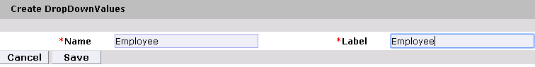
- Click Save.
- Configure the values for the Contractor field in the same way (Figure 9‑27).
Figure 9‑27 DropDown Values
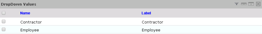
- Click Save > Save to save the configuration.
9.4.3.7. Modify Status Attribute
- Setup > Manual Configuration > Form customization > Attributes.
- Select the Status field from the list of Attributes, and then click Modify.
- Click the DropDown Values icon.
- On the popup window, click New, and enter Active in both the Name and Label fields (Figure 9‑28).
Figure 9‑28 Create DropDown Values
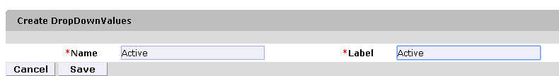
- Configure the values for InActive field in the same way (Figure 9‑29).
Figure 9‑29 DropDown Values
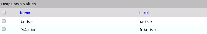
- Click Save > Save to save the configuration.
9.4.3.8. Identity & Access– Enable Identity
- Setup > Manual Configuration > Identity & Access > Enable Identity.
- Enable the following configuration for the “Identity DB” system (Figure 9‑30).
Figure 9‑30 Guardian Identity Configuration
9.4.4. Identity & Access > User Field Mapping
- Setup > Manual Configuration > Identity & Access > User Field Mapping.
- Select User = Identity (from the drop-down), and then click Go.
- Click the Create New button.
- Select the Custom Field, Primary Key, Visible In List, and Is Searchable fields, based on Table 9‑25. Select the checkboxes for each field that is identified with a “Yes” in Table 9‑25. For each field that is identified with a “No” in Table 9‑25, ensure that the checkbox is unchecked (cleared).
- Click the Save button to save the record.
- Repeat Steps 1 through 5 for all fields in Table 9‑25. If a mapping already exists for a particular field, leave the mapping as-is.
Table 9‑25 User Field Mapping
| Custom Field | Primary Key | Visible In List | Is Searchable |
|---|---|---|---|
| UserId | No | Yes | No |
| ValidFrom | No | Yes | No |
| ValidTo | No | Yes | No |
| FirstName | No | Yes | Yes |
| LastName | No | Yes | Yes |
| No | No | No | |
| Building | No | No | No |
| ManagerId | No | No | No |
| BadgeStatus | No | No | No |
| BadgeType | No | No | No |
| BadgeValidFrom | No | No | No |
| BadgeValidTo | No | No | No |
| Location | No | No | No |
| BadgeId | No | No | No |
| EmployeeType | No | No | No |
| Department | No | No | No |
| Password | No | No | No |
| Groups | No | No | No |
| ManagerName | No | No | No |
| ManagerLN | No | No | No |
| Manager | No | No | No |
| ManagerId | No | Yes | No |
| Status | No | No | No |
| Telephone | No | No | No |
| ImageUpload | No | No | No |
| Password_AD | No | No | No |
| PacsAllDoors | No | Yes | No |
| PacsHomeAccess | No | Yes | No |
| PacsWorkAccess | No | Yes | No |
9.4.4.1. Identity & Access > Recon Authoritative Fields
- Setup > Manual Configuration > Identity & Access > Recon Authoritative Fields.
- Click New.
- Select ALERTDBCONNECTOR from the Systems drop-down list, and select PacsAllDoors from the Authoritative Field drop-down list (Figure 9‑31).
- Click Save to save the mapping.
Figure 9‑31 Create Recon Authoritative Fields
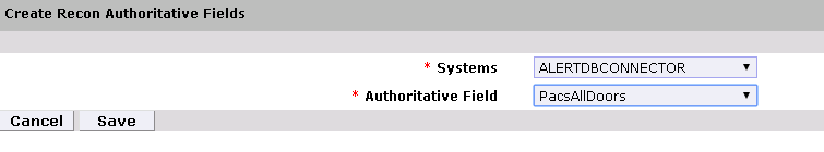
- Repeat Steps 1 through 4 to configure the mapping for fields PacsWorksAccess and PacsHomeAccess, as shown in Figure 9‑32.
Figure 9‑32 Guardian Recon Authoritative Fields
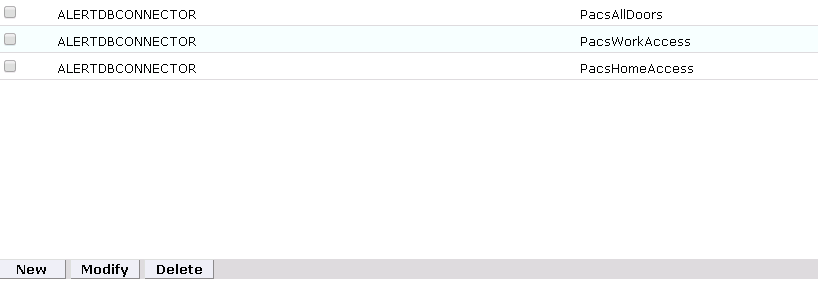
9.4.4.2. Identity & Access > Request Categories
Setup > Manual Configuration > Identity & Access > Request Categories.
Select the ChangeAccess Category name, and then click Modify.
On the Modify screen, make the following changes:
- In the Provisioning Actions section, deselect the Delimit User and Change Validity Dates checkboxes, if they are selected.
- Go to the Add Existing section, and select the System and Remove Role option from the Resources/Roles drop-down list.
Click Save to save the configuration.
9.4.4.3. Identity & Access > Provisioning > External Provisioning Attributes
- Setup > Manual Configuration > Identity & Access > Provisioning > External Provisioning Attributes
- Select the ACCESSIT PACS system from the list, and then click Configure.
- On the next screen, click New, and provide
LastNamein both the Name and Description fields (Figure 9‑33). - Click Save to save the configurations
Figure 9‑33 Create External Provisioning Attribute
- Repeat Steps 1 through 4 to configure the fields listed in Figure 9‑34.
Figure 9‑34 Configuring Fields
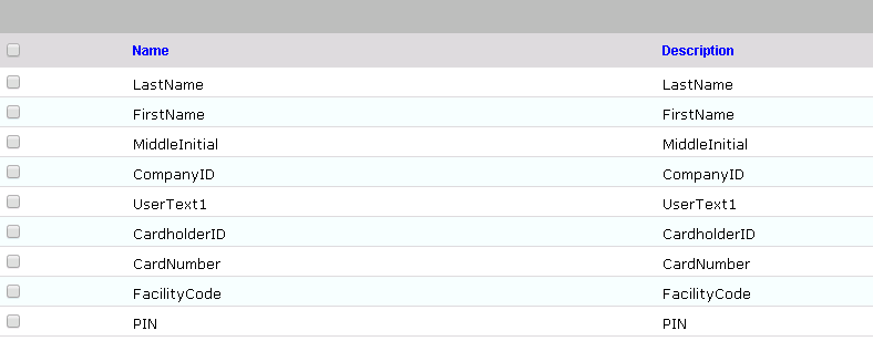
Note: The field names are case‑sensitive.
9.4.4.4. Identity & Access > Provisioning > Provisioning Mapping
- Setup > Manual Configuration > Identity & Access > Provisioning > Provisioning Mapping.
- Select ACCESSIT PACS, and then click Configure.
- On the next screen, click New, and then select UserText1 for the DB Connector Attribute Name (Figure 9‑35).
Figure 9‑35 Provisioning Mapping
- Click Save to save the mapping.
- Repeat Steps 1 through 4 to configure the other fields as shown in Figure 9‑36.
Figure 9‑36 Guardian DB Connector Attribute Mapping
9.4.4.5. Policy Engine > Rules
- Setup > Manual Configuration > Policy Engine > Rules.
- Click New.
- On the next screen, provide the information shown in Figure 9‑37.
Figure 9‑37 Define Rules
- Click Next.
- On the next screen, click New to define a new rule condition for the NewHire request category (Figure 9‑38).
Figure 9‑38 Define Condition
- Repeat Step 5 to define rule conditions for the other request categories (Remove User Access and ChangeAccess), as shown in Figure 9‑39.
Figure 9‑39 Remove User Access and ChangeAccess
- Repeat Steps 1 through 6 to configure Home Access Level New and WO Access Level New, as shown in Table 9‑26.
Table 9‑26 Guardian Manual Configuration Policy Engine Rules
| Rule Name | Entity Type | Rule Type | Description | Applicable to | Attributes | Selection Value |
|---|---|---|---|---|---|---|
| All Door Access New | Workflow | AlertAccess | All Door Access New | Suggest/ Default | PacsALLDoors AND Request Category |
|
| Home Access Level New | Workflow | AlertAccess | Home Access Level New | Suggest/ Default | PacsHomeAccess AND Request Category |
|
| WO Access Level New | Workflow | AlertAccess | WO Access Level New | Suggest/ Default | PacsWorkAccess AND Request Category |
|
9.4.4.6. Policy Engine > Suggest/Default Access
- Setup > Manual Configuration > Policy Engine > Suggest/Default Access.
- Click New, and enter the following information to create the All Door Access criteria (Figure 9‑40).
Figure 9‑40 All Door Access
- Click Next.
- On the next screen, enter
ACCESSIT PACSin the System Name field, and then click Search. - The System will appear in Search Results pane. Click the Add link under the Action column to add the system to the Selected Systems section.
- Click Next.
- On the next screen, enter
ALL DOORSin Role Name field, and then click Search. - The Role will appear in Search Results pane. Click the Add link under the Action column to add the role to the Selected Roles section.
- Click Save to save the configuration.
- Repeat Steps 1 through 9 to configure other criteria for Home Access Level New and WO Access Level New as listed in Table 9‑27.
Table 9‑27 Guardian Manual Configuration Policy Engine Rules
| Rule Name | Entity Type | Rule Type | Description | Applicable to | Attributes | Selection Value |
|---|---|---|---|---|---|---|
| All Door Access New | Workflow | AlertAccess | All Door Access New | Suggest/ Default | PacsALLDoors AND Request Category |
|
| Home Access Level New | Workflow | AlertAccess | Home Access Level New | Suggest/ Default | PacsHomeAccess AND Request Category |
3 True and ChangeAccess |
| WO Access Level New | Workflow | AlertAccess | WO Access Level New | Suggest/ Default | PacsWorkAccess AND Request Category |
|
- Select all existing Suggest Default Access criteria, other than the one listed in Table 9‑27, and click Delete to delete them.
9.4.4.7. Policy Engine > Rule Action Handler
- Setup > Manual Configuration > Policy Engine > Rule Action Handler.
- In the Action Handlers List page, select ReconChangeHandler, and then click Modify.
- On the next screen, select Recon Create Request for the Task type drop-down field, and then click Update Task.
- On the popup window, click the Value drop-down field, and then select **ChangeAccess **(Figure 9‑41).
Figure 9‑41 Modify Task
- Click Save Task, and then click Save.
9.4.4.8. Policy Engine > Policy Designer
Setup > Manual Configuration > Policy Engine > Policy Designer.
Select New to create a new policy designer as follows (Figure 9‑42):
- Name:
User Policy New - Rule Type: AlertAccess
- Description:
User Policy New
- Name:
Figure 9‑42 New Policy Designer
- Click Next.
- Drag the elements from the toolbar section that is available at the top of the page, place the elements onto the layout page, and then connect each node as
illustrated in Figure 9‑43.
Figure 9‑43 Tool Bar Section
represents the start button
represents the end button
represents a decision
represents a transition
represents a task
Guidelines to configure the policy:
- To place an element/node on the layout page, drag it from the toolbar, and then place it on the layout page.
- To connect two nodes, select the transition icon from the toolbar, and then mouse over to the first node and connect it to the other node in the same direction specified in Figure 9‑44.
- To provide text for a decision, task, or transition line, double-click on the corresponding node, and enter the text. After entering the text, press Enter to exit the edit mode.
Figure 9‑44 Guardian User Policy
- Click on the Step 1 decision box, and it will open popup window with some fields (Figure 9‑45).
- Enter
$masterUser[UserId].size='0'in the Condition field, and then press Enter.
Figure 9‑45 Tasks
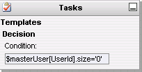
- Similarly, click on other steps (2 through 7), and configure the data based on Table 9‑28. For decision nodes, provide the Condition value; for task nodes, like Create User, Terminate User, Change Handler, and Error Handler, provide the Is Task Handler and Task Handler fields.
Table 9‑28 Guardian User Policy
| Step | Name | Type | Condition | Is Task Handler | Task Handler | Update Query |
|---|---|---|---|---|---|---|
| 1 | User ID Check | Decision | $masterUser[UserId].size='0' |
|||
| 2 | Create User | Task Handler | Yes | Recon New Hire | ||
| 3 | Terminate Check | Decision | $checkStatus[UserStatus,Active,InActive].action='LOCK' |
|||
| 4 | Terminate | Task Handler | Yes | Recon Terminate Handler | ||
| 5 | Remove Access Check | Decision | $checkAuthFields[].status='Yes' |
|||
| 6 | Error Handler | Task Handler | Yes | Recon Error Handler | ||
| 7 | Change Handler | Task Handler | Yes | Recon Change Handler |
9.4.4.9. Job Scheduler > Triggers Field Map
Setup > Manual Configuration > Job Scheduler > Triggers Field Map.
Click New.
Enter the following fields:
- Group Name:
Alert DbConnector Field Mapping - Description:
Alert DbConnector Field Mapping - Select Type:
Reconciliation
- Group Name:
After creating a field map, select the newly created map, and then select Configure.
Click New, and then create a mapping per Figure 9‑46.
Figure 9‑46 Guardian Job Scheduler Triggers Field Map
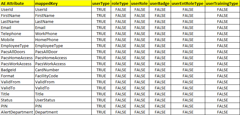
9.4.4.10. Job Scheduler > Triggers
- Setup > Manual Configuration > Job Scheduler > Triggers.
- Click New, and then create the following triggers in Table 9‑29.
Table 9‑29 Guardian AlertEnterprise DB Trigger
| Name | AlertDbConnectorTrigger |
| Description | AlertDbConnectorTrigger |
| Type | Reconciliation |
| Batch Size | 100 |
| Number of Attempts | 3 |
| Policy Designer for Users/Roles | User policy New |
| System: Reconciliation From | ALERTDBCONNECTOR |
| Reconciliation System | ALERTDBCONNECTOR |
| Field Mapping Group | ALERTDBCONNECTOR Field Mapping |
| User Type | True |
| User Role | True |
9.4.4.11. Job Scheduler > Scheduler
Setup > Manual Configuration > Job Scheduler > Scheduler.
Click New, and then enter the following fields (Figure 9‑47):
- Job Type: Reconciliation Job
- Job Name: <Job Name>
- Select the Global checkbox
- Reconciliation for: Users
- Reconciliation Type: Incremental Reconciliation
- Reconciliation Triggers: AlertDbConnectorTrigger
- Select the schedule as Immediate, Once, Periodically, or Advance. For Periodically, specify the Start At, End At, and Rerun every (duration of job frequency, which should be no less than every 2 minutes).
Figure 9‑47 Guardian Reconciliation Job
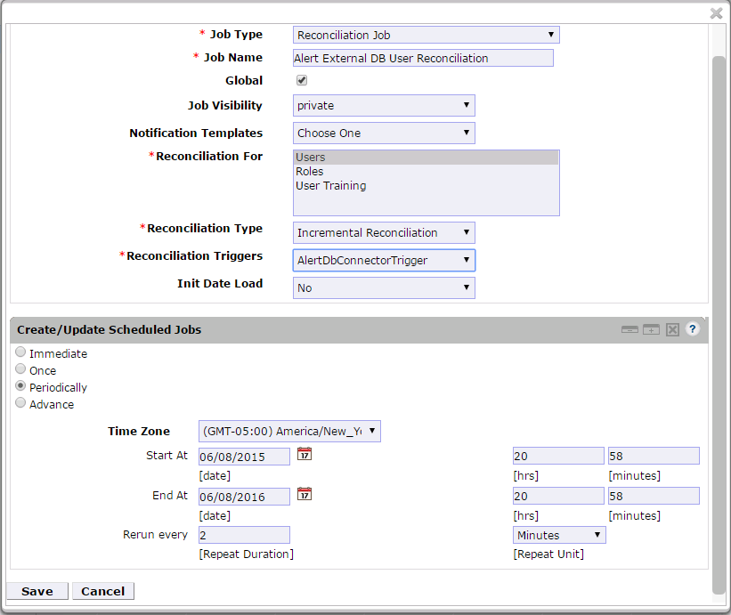
- Click Save.
10. PACS Server: RS2 Access It! Universal Server Installation
The Access It! Universal RS2 Technologies PACS Server is installed on the PACS Network to help control physical access to simulated facilities, rooms, etc. RS2 Technologies cards and card readers were also included in both builds. The RS2 Technologies PACS Server is installed on a VM that is running the Windows Server 2012 R2 OS.
10.1. Security Characteristics
Cybersecurity Framework Categories: PR.AC-2: Physical access to assets is managed and protected.
NIST SP 800-53 Revision 4 Security Controls: PE-2, PE-3, PE-4, PE-5, PE-6, PE-9
10.2. System Environment
The system for the PACS-Console Server configured by the NCCoE contains the following configuration settings and environmental constraints:
- Windows Server 2012 R2
- VM with CPU Quad Core 2.199 GHz
- VM with 8,192 MB of memory
- virtual hard disk containing 240 GB of storage
10.3. AIUNIVERSAL Installation
- Insert the AIUNIVERSAL compact disc (CD) into the compact disc read-only memory (CD-ROM) drive.
- Launch Setup64.exe as an administrator.
- Follow the install instructions:
- Select I do not have a SQL Server installed.
- When prompted to install SQL Server 2008 R2 Express Edition, select Yes.
- After the installation of SQL Server, select Install Access It! Universal.
- When prompted to install a Stand-Alone Server version of Access It!, select OK.
- When prompted by the install wizard, select Next.
- Read the license agreement, and then select Next if you agree with the terms of the agreement.
- Use the default installation folder C:\Program Files(x86)\RS2 Technologies\Access It! Universal\, and then select Next.
- When the installer is ready, select Next to continue.
- Select Close to exit the installer after completion.
10.4. Post Installation
- Launch Access It! by selecting it from the start menu.
- When prompted to select a server, enter the hostname of the server: PACS-CONSOLE.
- Log in with the default username and password.
10.4.1. Connect Access It! Universal to Door Controller
Main > Hardware > Channels.
Create a new channel.
For the Channel Type, select IP Server.
Ensure that the Protocol Type is SCP.
Select Save.
Create a new SCP.
Under the General tab, ensure that the Model is set to EP-1501Plus.
Under the Comm tab, ensure that the Channel is set to Channel 000 (the channel that was just created).
Verify the following settings:
TCP/IP Settings:
- IP Address:
172.16.7.101 - Port Number:
3001
- IP Address:
Encryption Settings: None.
Under the Card Formats tab:
- Format Name: 26 Bit Wiegand Facility code:
20 - Format Name: 26 Bit Wiegand Facility code:
219
- Format Name: 26 Bit Wiegand Facility code:
Save changes to SCP 000.
Under SIOs, edit SCP 000 – SIO 00.
Under the General tab, ensure that the Model is set to EP-1501.
Edit SCP 000 – SIO 01.
Under the General tab, ensure that the Model is set to MR-52.
Under Main > Hardware, select Installed Readers.
Create SCP 000 – SIO 00-Reader 1.
Create SCP 000 – SIO 01-Card Reader.
Create SCP 000 –SIO 01-MRDT Keypad.
Under Configuration > Access Levels, create New Access Level.
Create a new access level:
- Access Level Name: All Doors
- Assigned Readers for All Doors: SCP 000 – SIO 01-Card Reader and SCP 000 – SIO 01-MRDT Keypad
- Access Level Name: Home Access Level
- Assigned Reader for Home Access Level: SCP 000 – SIO 01-MRDT Keypad
- Access Level Name: Work Order Access Level
- Assigned Reader for Work Order Access Level: SCP 000 – SIO-Card Reader
10.4.2. Enable TCP/IP to SQL 2008 R2 Server
- Launch Microsoft SQL Server Configuration Manager.
- Expand SQL Server Network Configuration (32-bit).
- Select Protocols for AIUNIVERSAL.
- Right-click on TCP/IP, and then select Properties.
- Select tab IP Addresses.
- Under IP1, ensure that IP Address is set to
0.0.0.0, and that TCP Port is set to1433. - Under IPALL, ensure that TCP Dynamic Ports is set to 52839, and that TCP Port is set to
1433. - Restart the SQL server by selecting SQL Server Services, and then right-click on SQL Server (AIUNIVERSAL) and select Restart.
11. Privileged User Access Control: TDi ConsoleWorks Server Installation
The TDi ConsoleWorks server was installed in two different locations in the builds. It was installed on the OT network to control and monitor access between OT technicians and physical devices, such as the RTUs and the RADiFlow ICS firewall. The following subsections provide details on the steps that are needed to install and configure each of these servers.
11.1. Security Characteristics
Cybersecurity Framework Categories:
- PR.PT-1: Audit/log records are determined, documented, implemented, and reviewed in accordance with policy.
- PR.PT-3: Access to systems and assets is controlled, incorporating the principle of least functionality.
NIST SP 800-53 Revision 4 Security Controls: AU Family, AC-3, CM-7
11.2. ConsoleWorks Server Installation
ConsoleWorks was installed on the OT network to control and monitor access between OT technicians and physical devices, such as the RTUs and the RADiFlow ICS firewall. ConsoleWorks uses the OT directory to authenticate users who are requesting access to these devices. It also establishes a permanent SSH or telnet connection to each of the RTUs and ICS firewall by using pre-established usernames and passwords. As users request access and are authenticated, ConsoleWorks makes the cross-connection from the user to the specific SSH or telnet session to allow access. Once the cross-connection is established, the user has access to the device to make any changes needed. When users complete their task, they log off the connection, and ConsoleWorks removes the cross-connect between the user and the SSH or telnet session.
ConsoleWorks logs all user access requests and all of the traffic on the session, and can alert on any pre-defined aspect of the traffic. Directory-based authentication is used to manage the user access in near‑real‑time.
On the OT network, the ConsoleWorks Server is installed on a VM that is running the Windows Server 2012 R2 (hardened server OS) image, as explained in Section 3.1.1.
11.2.1. System Environment
The system for the OT Network ConsoleWorks Server configured by the NCCoE contains the following configuration settings and environmental constraints:
- Windows Server 2012 R2 OS
- VM with CPU Quad Core 2.199 GHz
- VM with 8,192 MB of memory
- virtual hard disk containing 240 GB of storage
11.2.2. ConsoleWorks Server Installation on the OT Network
- After installing the OS, download the TDi Technologies Installer from http://support.tditechnologies.com/get_consoleworks.
- Launch the
cw_server_v4.9-0u0.exeapplication. The installer requires administrative privileges to execute. - When prompted by Windows User Account Control, select Yes to continue.
- The ConsoleWorks Server InstallShield wizard should display a welcome message. Select Next to continue.
- When prompted by the InstallShield wizard to accept the license agreement, read carefully. If you agree with the license terms, select Next to continue with the installation.
- Enter the User Name and Organization fields, then select Next to continue.
- Select Complete when prompted for setup type, then select Next to continue.
- Click Install to begin the installation of the ConsoleWorks Server.
- After the InstallShield wizard has completed, ensure that Launch upgrade script (if upgrading from 32-bit) is unchecked.
- Select Finish.
11.2.3. Post-Installation Configuration of ConsoleWorks on the OT Network
- Copy TDi Technologies license key files into C:\ProgramData\ConsoleWorks/Server\LMF\TDI_Licenses
- Go to Start > Run > services.msc.
- Right-click on the ConsoleWorks Server Service, and then select Properties.
- Select Start to start the service, and then change the Startup Type from Manual to Automatic.
- Select Apply to save the changes. Both the ConsoleWorks Server and ConsoleWorks LMF Server services should be running.
- Test the browser connectivity by going to http://localhost:5176. The default account
is
CONSOLE_MANAGER. The default password is: Setup.
11.2.4. Configuring External Authentication for the OT Network ConsoleWorks Server
- From the left menu, select the SECURITY tab.
- Select External Authentication.
- Ensure that the Enable External Authentication checkbox has been selected.
- Select Add.
- Parameter 1:
OT-ES-IDAM-B1 - Parameter 2:
CW\_ - Required Profile:
CONSOLE_WORKS - Template User:
CONSOLE_MANAGER - Leave all other fields blank.
- Select Next.
- Enter a Username and Password to test External Authentication settings.
- Select Next, and then select Save.
12. ICS/SCADA Firewall: RADiFlow
A RADiFlow switch is installed on the physical network that represents the ICS component that can be accessed and controlled via the OT network. A RADiFlow management workstation is installed on the OT network. The RADiFlow Management Workstation is installed on a VM that is running the Windows 7 Enterprise OS.
12.1. Security Characteristics
Cybersecurity Framework Categories: PR.PT-3: Access to systems and assets is controlled, incorporating the principle of least functionality.
NIST SP 800-53 Revision 4 Security Controls: AC-3, CM-7
12.2. OT Network RADiFlow Management Workstation Installation
12.2.1. Installing iSIM
- Launch the iSIM installer as an administrator.
- Set the Destination Directory to C:\Program Files (x86).
- Leave the default settings for all other options.
12.2.2. iEMS
Launch iEMS from the start menu.
From the menu items, select System > Switch Initialization > Force Switch Model > 3180.
In the main windows dialog box, enter the switches IP address
172.16.6.4, and then select Refresh.From the menu items, select Configuration > Interfaces > Serial Ports….
Select the Terminal Server tab, and ensure that the Service 1 and Service 2 dialog boxes are checked.
Under Service 1, enter these settings:
- Service ID:
1 - Local IP Address:
172.16.6.100 - Telnet Port:
2050 - Null CR Bit Mode:
OFF
- Service ID:
Under Service 2, enter these settings:
- Service ID:
2 - Local IP Address:
172.16.6.100 - Telnet Port:
2051 - Null CR Bit Mode:
OFF
- Service ID:
Select Create/Update.
Select the Serial Ports tab; ensure that the Port-1 and Port-2 dialog boxes are checked.
Under Port 1, enter these settings:
- Application: Terminal Server
- Local Position: Slave
- Service-id: 1
- Operation Mode: Transparent
- Buffer Mode: byte
- Protocol: any
- Baudrate: 9600
- Databits: 8
- Stopbits: 1
- Parity: no
- Allowed-latency: 6
- Bus-idle-time: 30
- Dtr-dsr: enable
- Rts-cts: enable
- Local-dsr-delay: 0
- Local-cts-delay: 0
- Tx-delay: 10
- Bits-for-sync1: 28
- Bits-for-sync2: 1
- Unit-id length: 2
- Iec101-link-address-len: 2
Under Port 2, enter these settings:
- Application: Terminal Server
- Local Position: Slave
- Service-id: 2
- Operation Mode: Transparent
- Buffer Mode: byte
- Protocol: any
- Baudrate: 9600
- Databits: 8
- Stopbits: 2
- Parity: no
- Allowed-latency: 6
- Bus-idle-time: 30
- Dtr-dsr: enable
- Rts-cts: enable
- Local-dsr-delay: 0
- Local-cts-delay: 0
- Tx-delay: 10
- Bits-for-sync1: 28
- Bits-for-sync2: 1
- Unit-id length: 2
- Iec101-link-address-len: 2
Select Create/Update.
13. Ozone: MAG Installation
Four Ozone components are installed on the IdAM network: Console, Authority, Server, and Envoy. These components are installed on VMs running the CentOS 7 image.
13.1. Security Characteristics
Cybersecurity Framework Categories: PR.AC-4: Access permissions are managed, incorporating the principles of least privilege and separation of duties.
NIST SP 800-53 Revision 4 Security Controls: AC-2, AC-3, AC-5, AC-6, AC-16
13.2. Ozone Console Installation and Authority Configuration
Install CA Certificate into Trusted Root store (MAG_DEV_CA.crt).
Install Ozone Authority Certificate into Trusted People store (ozoneauthority.crt).
Install Administrator keys into Personal store (admin1.crt and admin2.crt).
Run Setup Ozone Console.exe.
Run Ozone Console.
Go to Configuration>Ozone Authority>New (Figure 13‑1).
In the Proof Settings tab:
- Select SHA256 for the Entity Digest Algorithm.
- Select SHA256withRSA for the Proof Signature Algorithm.
Figure 13‑1 Ozone Proof Settings
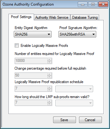
In the Authority Web Service tab (Figure 13‑2):
- Set the HTTPS Port to
443. - Select SHA1withRSA for the Message Signature Algorithm.
- Set the HTTPS Port to
Figure 13‑2 Ozone Authority Web Service
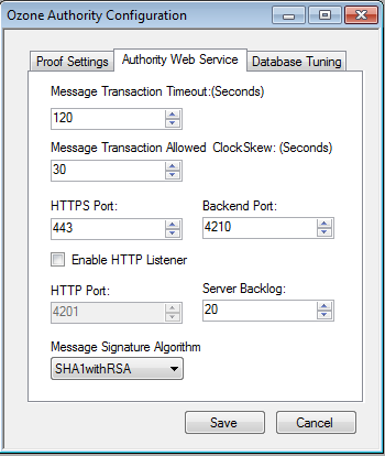
- Click Save.
- Select a certificate to be used to digitally sign the configuration (Admin 1).
- Save the file as AuthorityConfiguration.xml.
- Secure Copy the file to Ozone Authority machine.
13.3. Ozone Authority Installation
Create keys and certificates, and store them in Java Keystore (JKS).
[root@ozone ~]# yum install java
[root@ozone ~]# yum install mariadb-server
[root@ozone ~]# reboot
[root@ozone ~]# systemctl start mariadb
[root@ozone ~]# systemctl enable mariadb
[root@ozone ~]# mysql_secure_installation
[root@ozone ~]# mysql -u root –p

MariaDB> create database ozone;
Query OK, 1 row affected (0.02 sec)

MariaDB> create user 'ozone'@'localhost' identified by 'password';
Query OK, 0 rows affected (0.00 sec)

MariaDB> grant all privileges on ozone.* to 'ozone'@'localhost';
Query OK, 0 rows affected (0.00 sec)

MariaDB> flush privileges;
Query OK, 0 rows affected (0.00 sec)

[root@ozone local]# cd /usr/local/
[root@ozone local]# tar -xzf ~/Ozone\ Authority-2014.tar.gz
[root@ozone local]# mv ~/AuthorityConfiguration.xml authority/conf/
[root@ozone local]# mv ~/AuthorityLicense.xml authority/conf/
[root@ozone local]# mv ~/authority.jks authority/keystores/
[root@ozone local]# mv ~/admin1.cer authority/bin/
[root@ozone local]# mv ~/admin2.cer authority/bin/
[root@ozone local]# cd authority/bin/
[root@ozone bin]# ./startAuthority.sh
Configuration file not found, would you like to create a new
installation? [Y] Y

***WARNING***
This product MUST be installed by an Ozone Certified
Engineer. Pericore, Inc. cannot be held liable for damages resulting
from negligent or fraudulent actions of unauthorized or unqualified
administrators. Please review all documentation thoroughly before
continuing. Continuation of this configuration process represents an
agreement to abide by the Pericore EULA.
Do you wish to continue? [N] : y

Please select the license file for this Ozone Authority.:
1: /usr/local/authority/conf/AuthorityLicense.xml
2: Other...
Choice [1] : 1

Please select the configuration file for this Ozone Authority.:
1: /usr/local/authority/conf/AuthorityConfiguration.xml
2: Other...
Choice [1] : 1

Do you wish to set any passphrase complexity requirements? [N] : N

Note: If you require passphrase at start, you will not be able to
restart this Ozone Authority without user intervention.
Do you wish to require a passphrase to start this Ozone Authority? [N] N

Using keystore type: RSA

Do you have an existing keystore you wish to use for this Ozone Authority? [Y] : Y

Please select the keystore file for this Ozone Authority::
1: /usr/local/authority/keystores/authority.jks
2: Other...
Choice [1] : 1
Please enter the passphrase. : 123456
May 15, 2015 1:24:22 PM com.pericore.util.PericoreProvider jsafeJCEinit
POST: [FIPS] FIPS-140 compliance self-test passed.

What type of database do you wish to use?:
1: SQLSERVER
2: ORACLE
3: MYSQL
Choice [1] : 3
Please enter the hostname or IP address of the database server: [ozone] : localhost
Please enter the port number for the database: [3306] 3306
Please enter the username for the database: [] : ozone
Please enter the database password: password
Using only available database: ozone

How many initial administrators would you like to create? [2] : 2
Page 1 | Current Directory:
[00] ../
[01] lib/
[02] admin1.cer
[03] admin2.cer

Please select the file containing the administrators certificate: [ # ] : 2
3Page 1 | Current Directory:
[00] ../
[01] lib/
[02] admin1.cer
[03] admin2.cer

Please select the file containing the administrators certificate: [ # ] : 1
Please enter distinguished name(DN) of the starting Organizational
Unit (OU) for this proof tree: [OU=Ozone] : ou=Ozone, dc=NCCOE, dc=test
Is: ou=Ozone, dc=NCCOE, dc=test correct? [Y] : Y
Please enter the minimum number of administrators required to approve
changes to the initial proofs: [1] : 1
Please enter a name for the initial publication schedule: [Primary Schedule] : Daily
Please enter the publication interval: [12] : 12
Please select the time unit::
1: Minute
2: Hour
3: Day
Choice [1] : 2
Please enter the validity period after publication: [12] : 12
Please select the validity period time unit::
1: Minute
2: Hour
3: Day
Choice [1] :

Please enter a name for the initial distribution point for proofs. [File Distribution Point] : LDAP Distribution Point

Please enter the initial distribution point for proofs. This may be changed later. [file:///usr/local/authority/proofs/] : ldap://ozoneauthority/
Configuration File: /usr/local/authority/conf/AuthorityConfiguration.xml
May 15, 2015 1:25:16 PM com.pericore.util.ObjectIdentifierFactory$OIDDataLoader debug
INFO: ObjectIdentifierFactory Read 240.165 kb in 2.511 ms; Indexed 2,415 Arcs in 51.731 ms; 2,310(1,054:5) keys => 2.003 kb
Created proof ou=Master Authorization Group, ou=Ozone, dc=NCCOE, dc=test in the database.
Created proof ou=Applications, ou=Master Authorization Group, ou=Ozone, dc=NCCOE, dc=test in the database.
Created proof ou=Groups, ou=Master Authorization Group, ou=Ozone, dc=NCCOE, dc=test in the database.
Created proof ou=Attribute Types, ou=Master Authorization Group, ou=Ozone, dc=NCCOE, dc=test in the database.

Allowing a user certificate to be associated with a directory GUID
allows for a migration path from username and password to a PKI based
authentication and authorization mechanism. However, this method
lowers the initial security settings by relying on a directory for the
association. Please be sure you understand the risks associated with
this method before allowing this mechanism to be used.
Would you like to allow users certificates to be associated with a directory GUID? [N] : N
Do you wish to display a logon message? [N] : N

Ozone Authority
Version: 2014 - 4.0.1 (Build: 475)
Copyright Pericore, Inc. 2014
-----------------------------------
Started at: May 15, 2015 1:24:13 PM EDT
Licensed to: NCCOE
-----------------------------------

Built: ou=Master Authorization Group, ou=Ozone, dc=NCCOE, dc=test in 0:00:00.304.
Built: ou=Applications, ou=Master Authorization Group, ou=Ozone, dc=NCCOE, dc=test in 0:00:00.243.
Built: ou=Groups, ou=Master Authorization Group, ou=Ozone, dc=NCCOE, dc=test in 0:00:00.215.
Built: ou=Attribute Types, ou=Master Authorization Group, ou=Ozone, dc=NCCOE, dc=test in 0:00:00.214.
Push Certificates loaded with: 0 certificates

Started HTTPS Listener on port: 443
Ozone Authority>

[root@ozone ~]# yum install 389-ds-base
[root@ozone ~]# vi /etc/hosts
Modify the first line of hosts file so that it is the same as below:
127.0.0.1 ozoneauthority.nccoe.test localhost localhost.localdomain localhost4 localhost4.localdomain4
Configure the directory server
[root@ozone ~]# setup-ds.pl

=======================================================================
This program will set up the 389 Directory Server.

It is recommended that you have "root" privilege to set up the software.
Tips for using this program:
- Press "Enter" to choose the default and go to the next screen
- Type "Control-B" or the word "back" then "Enter" to go back to the previous screen
- Type "Control-C" to cancel the setup program

Would you like to continue with set up? [yes]: yes

=======================================================================
Your system has been scanned for potential problems, missing patches,
etc. The following output is a report of the items found that need to
be addressed before running this software in a production
environment.

389 Directory Server system tuning analysis version 23-FEBRUARY-2012.

NOTICE : System is x86_64-unknown-linux3.8.13-68.2.2.el7uek.x86_64 (1 processor).

NOTICE : The net.ipv4.tcp_keepalive_time is set to 7200000 milliseconds
(120 minutes). This may cause temporary server congestion from lost
client connections.

WARNING: There are only 1024 file descriptors (soft limit) available, which
limit the number of simultaneous connections.

WARNING : The warning messages above should be reviewed before proceeding.

Would you like to continue? [no]: yes

=======================================================================
Choose a setup type:

1. Express
Allows you to quickly set up the servers using the most
common options and pre-defined defaults. Useful for quick
evaluation of the products.

2. Typical
Allows you to specify common defaults and options.

3. Custom
Allows you to specify more advanced options. This is
recommended for experienced server administrators only.

To accept the default shown in brackets, press the Enter key.

Choose a setup type [2]: 2

=======================================================================
Enter the fully qualified domain name of the computer
on which you're setting up server software. Using the form
.
Example: eros.example.com.

To accept the default shown in brackets, press the Enter key.

Warning: This step may take a few minutes if your DNS servers
cannot be reached or if DNS is not configured correctly. If
you would rather not wait, hit Ctrl-C and run this program again
with the following command line option to specify the hostname:

General.FullMachineName=your.hostname.domain.name

Computer name [ozone.mountaireygroup.com]: ozoneauthority.nccoe.test

=======================================================================
The server must run as a specific user in a specific group.
It is strongly recommended that this user should have no privileges
on the computer (i.e. a non-root user). The setup procedure
will give this user/group some permissions in specific paths/files
to perform server-specific operations.

If you have not yet created a user and group for the server,
create this user and group using your native operating
system utilities.

System User [nobody]: nobody
System Group [nobody]: nobody

=======================================================================
The standard directory server network port number is 389. However, if
you are not logged as the superuser, or port 389 is in use, the
default value will be a random unused port number greater than 1024.
If you want to use port 389, make sure that you are logged in as the
superuser, that port 389 is not in use.

Directory server network port [389]: 389

=======================================================================
Each instance of a directory server requires a unique identifier.
This identifier is used to name the various
instance specific files and directories in the file system,
as well as for other uses as a server instance identifier.

Directory server identifier [ozoneauthority]: ozoneauthority

=======================================================================
The suffix is the root of your directory tree. The suffix must be a valid DN.
It is recommended that you use the dc=domaincomponent suffix convention.
For example, if your domain is example.com,
you should use dc=example,dc=com for your suffix.
Setup will create this initial suffix for you,
but you may have more than one suffix.
Use the directory server utilities to create additional suffixes.

Suffix [dc=nccoe, dc=test]: dc=nccoe, dc=test

=======================================================================
Certain directory server operations require an administrative user.
This user is referred to as the Directory Manager and typically has a
bind Distinguished Name (DN) of cn=Directory Manager.
You will also be prompted for the password for this user. The password must
be at least 8 characters long, and contain no spaces.
Press Control-B or type the word "back", then Enter to back up and start over.

Directory Manager DN [cn=Directory Manager]: cn=Directory Manager
Password: password
Password (confirm): password
Your new DS instance 'ozoneauthority' was successfully created.
Exiting . . .
Log file is '/tmp/setup_C4mdK.log'
Setup the directory structure
Modify the file /usr/local/authority/bin/389SetupDirectory.ldif
Set the correct DN structure and passwords for the ozone authority user and tree
389SetupDirectory.ldif
#Create the User for Ozone Authority
dn: uid=ozone, ou=Special Users, dc=nccoe, dc=test
changetype: add
objectClass: inetorgperson
objectClass: organizationalPerson
objectClass: person
objectClass: top
cn: Ozone Authority
sn: Authority
givenName: Ozone
uid: ozone
userPassword: P@$$word

#make the people writable by ozone
dn: ou=People, dc=nccoe, dc=test
changetype: modify
add: aci
aci: (targetattr="*")(version 3.0;acl "ozone authority";allow (all)(userdn = "ldap:///uid=ozone, ou=Special Users, dc=nccoe, dc=test");)

#Create the Ozone OU
dn: ou=Ozone, dc=nccoe, dc=test
changetype: add
objectClass: organizationalUnit
objectClass: top
ou: Ozone
aci: (targetattr="*")(version 3.0;acl "ozone authority";allow (all)(userdn = "ldap:///uid=ozone, ou=Special Users, dc=nccoe, dc=test");)

#Create required Attributes and Object Classes
dn: cn=schema
changeType: modify
add: attributetypes
attributetypes: ( 1.3.6.1.4.1.26135.1.1.1.2 NAME 'authorizationProof' DESC 'Ozone Authorization Proof' SYNTAX 1.3.6.1.4.1.1466.115.121.1.40 SINGLE-VALUE X-ORIGIN 'user defined' )
attributetypes: ( 2.23.136.1.1.2 NAME 'cscaMasterList' DESC 'CSCA Master List' SYNTAX 1.3.6.1.4.1.1466.115.121.1.40 SINGLE-VALUE X-ORIGIN 'user defined' )

dn: cn=schema
changeType: modify
add: objectclasses
objectclasses: ( 1.3.6.1.4.1.26135.1.1.3 NAME 'ozoneAuthority' DESC '' SUP top STRUCTURAL MAY (authorizationProof $ cscaMasterList) X-ORIGIN 'user defined' )
Modify the directory using the LDIF
[root@ozone bin]# ldapmodify -x -D "cn=Directory Manager" -W -f /usr/local/authority/bin/389SetupDirectory.ldif
Enter LDAP Password:
adding new entry "uid=ozone, ou=Special Users, dc=nccoe, dc=test"

modifying entry "ou=People, dc=nccoe, dc=test"

adding new entry "ou=Ozone, dc=nccoe, dc=test"

modifying entry "cn=schema"

modifying entry "cn=schema"
13.4. Ozone Console Server Configuration
Before proceeding, ensure that OzoneAuthority has been started by running startauthority.sh on the OzoneAuthority machine.
- Open Ozone Console.
- Go to File > Properties (Figure 13‑3).
- Enter the Ozone Authority URL.
- Click Select Certificate, and then select the Ozone Authority Certificate.
- Select SHA1withRSA as the Message Signature Algorithm.
- Click Save to the connection information.
Figure 13‑3 Ozone Authority Connection Information
Create the publication point for the proofs:
- Select Publication > Add Publication Point > Add LDAP Publication Point (Figure 13‑4).
- Enter a name for the publication point.
- Enter the hostname or IP address of the directory server.
- Enter a base context, if any.
- Select the port.
- Enter the name of the user who has permissions to write to the directory.
- Enter the password for the user.
- Confirm the password.
Figure 13‑4 Ozone LDAP Publication Point
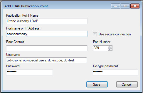
Import the desired groups from RSA Adaptive Directory:
- Right-click on the Groups proof.
- Select Import Group from Active Directory (Figure 13‑5).
- Enter the directory connection information.
Figure 13‑5 Ozone Directory Connection Information
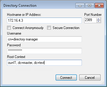
- Select a group to import (Figure 13‑6).
- Check the box to Import New Entities.
- Check the box to Import Associated Groups.
- Select Import.
Figure 13‑6 Ozone Import Group from Directory
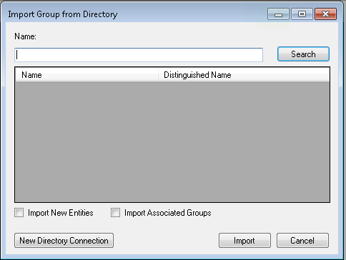
- Select the Schedule, Publication Points, and Distribution Points, as shown in Figure 13‑7.
Figure 13‑7 Ozone New Proof Information
- Click the Administrators tab, as shown in Figure 13‑8.
- Click the Add Administrators button.
- Select the users who will administer the proof.
- Select Add Entities.
Figure 13‑8 Ozone New Proof Administrators
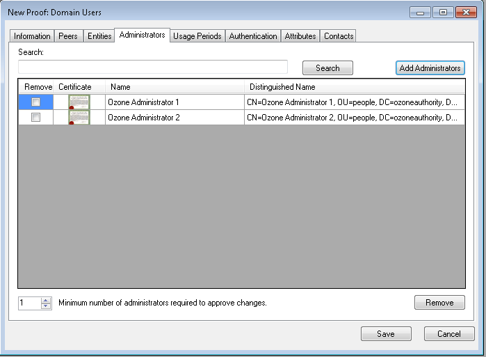
- Click Save.
Create the Ozone Server Configuration:
- Select Configuration > Ozone Server > New….
- Click Add proof from tree….
- Select a proof that the Ozone Server should use for authorizations, as shown in Figure 13‑9.
Figure 13‑9 Ozone Peer Proofs
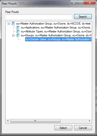
- Set the number of proof references (depth) that the proof may follow to authorize a credential, as shown in Figure 13‑10.
- Ensure that the locations where the Ozone Server will retrieve the proof are correct.
Figure 13‑10 Ozone Add Authorization Proof
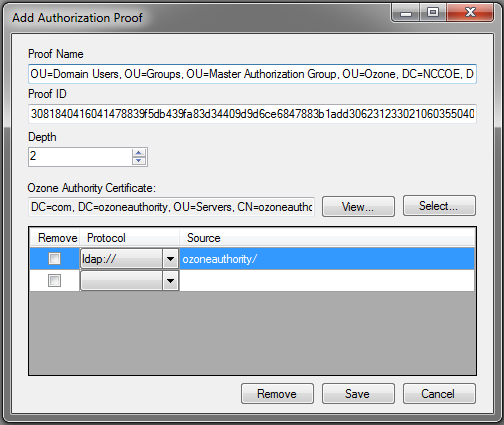
- Click Save.
- Repeat Steps 2 through 6 until you have selected all of the proofs that the Ozone Server should initially retrieve for authorizations.
- Click Save configuration, as shown in Figure 13‑11.
Figure 13‑11 Ozone Server Configuration
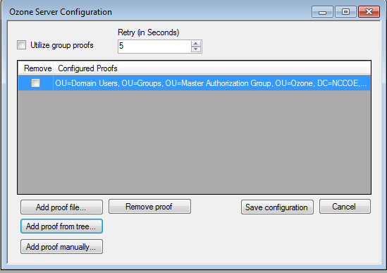
- Select a certificate to be used to digitally sign the configuration.
- Save the file as ServerConfiguation.xml.
- Secure copy the file to the Ozone Server machine.
13.5. Ozone Server Installation
Create keys and certificates, and store them in JKS.
[root@ozone ~]# yum install java
[root@ozoneserver ~]# cd /usr/local/
[root@ozoneserver local]# tar -xzf ~/Ozone\ Server-2014.tar.gz
[root@ozoneserver local]# mkdir /usr/local/server/bin/conf/
[root@ozoneserver local]# cp ~/server.jks server/bin/conf/
[root@ozoneserver local]# cp ~/ServerConfiguration.xml server/bin/conf/
[root@ozoneserver local]# cp ~/ServerLicense.xml server/bin/conf/

[root@ozoneserver bin]# ./startServer.sh
POST [MAIN] v2.1.301

_______ __________ _______ __ _ ________
/ ___ \ _____ // ___ \ | \ | | ______| (R)
| / \ | / /| / \ || \ \ | | |
| | | | / / | | | || |\ \ | | |____
| | | | / / | | | || | \ \ | | ____|
| | | | / / | | | || | \ \| | |
\ \___/ // /___ \ \___/ /| | \ \ | |______
\_______//________ \_______/ |_| \__|________|
_____
/ ____|
| (___ ___ _ ____ _____ _ __
\___ \ / _ \ '__\ \ / / _ \ '__|
____) | __/ | \ V / __/ |
|_____/ \___|_| \_/ \___|_|

Ozone(R) Server copyright (c) Pericore, Inc. 2007-2011
------------------------------------------------------
Fri May 15 14:31:33 EDT 2015

May 15, 2015 2:31:35 PM com.pericore.util.PericoreProvider jsafeJCEinit
POST: [FIPS] FIPS-140 compliance self-test passed.
Found Java version: 1.8.0_31
Working in: /usr/local/server/bin
/usr/local/server/bin/conf/server.cfg not found. Run setup [Y] : Y
env.work/usr/local/server/bin
Found Java Version: 1.8.0_31

Ozone Server Setup Utility
***WARNING***
This product MUST be installed by a Pericore Certified Engineer. Pericore, Inc. cannot be held liable for damages resulting from negligent or fraudulent actions of unauthorized or unqualified administrators. Please review all documentation thoroughly before continuing. Continuation of this configuration process represents an agreement to abide by the Pericore EULA.
I agree to all terms and conditions set forth by Pericore, Inc. [N] : y
Enable Startup Password? [N] : n
May 15, 2015 2:31:37 PM com.pericore.util.ObjectIdentifierFactory$OIDDataLoader debug
INFO: ObjectIdentifierFactory Read 240.165 kb in 3.313 ms; Indexed 2,415 Arcs in 52.438 ms; 2,310(1,054:5) keys => 2.003 kb
Server Configuration Directory:
1: /usr/local/server/bin/conf
2: Other...
Choice [1] : 1

Select the XML License File:
1: /usr/local/server/bin/conf/ServerLicense.xml
2: Other...
Choice [1] : 1

Select the XML Configuration File:
1: /usr/local/server/bin/conf/ServerConfiguration.xml
2: Other...
Choice [1] : 1

Page 1 | Current Directory: /usr/local/server/bin
[00] ../
[01] lib/
[02] conf/
Select Server Identity Keystore [ # ] : 2
Page 1 | Current Directory: /usr/local/server/bin/conf
[00] ../
[01] server.jks

Select Server Identity Keystore [ # ] : 1
Enter password for server.jks : 123456
Is the Private Key Alias 'server' correct? [Y] : Y

Enable logging? [Y] : Y
Log File Roll Size (Kb) [512] : 512

Configured Client Services: 0
Choose an option:
1: Configure Authorization Service
2: Configure a Proof Proxy
3: Configure an Info Page
4: Configure a Push Service
5: Done Configuring Web Services
Choice [1] : 1

Configuring XACML Authorization Service
Service Port [8080] : 443
Service Context [/AuthorizationService] : /AuthorizationService
Enable WS-Security? [Y] : Y
SOAP Signature Method:
1: RSA_SHA1
2: RSA_SHA256
3: RSA_SHA384
4: RSA_SHA512
Choice [1] : 2
Enable WS-Security Client Authentication? [N] : N
Configured Client Services: 1

Choose an option:
1: Configure Authorization Service
2: Configure a Proof Proxy
3: Configure an Info Page
4: Configure a Push Service
5: Done Configuring Web Services
Choice [1] : 5

Enable SSL? [N] : y
Service Port [8080] : 443
Enable SSL Client Authentication? [N] : N
Enable SSL? [N] : N
Modify Advanced Performance Options? [N] : N

Writing server configuration...
Thank you for choosing Ozone Server
Goodbye.

[root@ozoneserver local]# /usr/local/server/bin/startServer.sh
13.6. Ozone Envoy Installation
Ozone Envoy was installed, but was not utilized in the builds. The functions that it provides (automated certificate revokation lists [CRLs] and certificate collection) were not required in the solution.
Create keys and certificates, and store them in JKS.
[root@ozoneenvoy ~]# yum install java
[root@ozoneenvoy ~]# cd /usr/local/
[root@ozoneenvoy local]# tar -xzf ~/Ozone\ Envoy-2014.tar.gz
[root@ozoneenvoy local]# cp ~/envoy.jks envoy/bin/
Edit the envoy.txt file to set configuration options
### Ozone Suite (c) Pericore, Inc. 2007-2014.
### All rights reserved.

################################################################################
### envoy.txt - Ozone Envoy 2014 Configuration File ###
###    ###
### Author: Jacob Dilles <[email protected]> ###
###    ###
### Date: 1 Jan 2014   ###
###    ###
### Notes: This is a sample Ozone Envoy 4.1.0 Setup Configuration File ###
### demonstrating configuration options for Mobile Enrollment. ###
###    ###
### In a production environment, you should exclude the /pass= ###
### properties and provide them on the command line during setup.###
### After installation is complete, this file should be deleted ###
### or 'chown root; chgrp 0; chmod 000' to secure it. ###
################################################################################

### General Envoy Configuration

############################################################
############ Identity Keystore Configuration ##############
############################################################
### This keystore is used for:
### - Authenticating with Ozone Authority
### - Secure log signing
system/identity/store=envoy.jks

####### Authority Listener Configuration
### This web service endpoint listens for push configuration and fetch requests
### from Ozone Authority. It should match what you entered in Ozone Console

#authority/host.name=
authority/port=4242
authority/path=/
authority/mode=ANY

### Authority Web Service Endpoint Logging
authority/log/enable=true
authority/log/path=var/log
authority/log/rollsize=10485760
authority/log/format=CLF

######################################################
############ Enrollment Configuration ################
######################################################

### Enable enrollment
enroll/enable=false

[root@ozoneenvoy bin]# ./startEnvoy.sh

May 15, 2015 3:09:04 PM com.pericore.util.ObjectIdentifierFactory$OIDDataLoader debug
INFO: ObjectIdentifierFactory Read 240.165 kb in 14.366 ms; Indexed 2,415 Arcs in 63.198 ms; 2,310(1,054:5) keys => 2.003 kb
May 15, 2015 3:09:06 PM com.pericore.util.PericoreProvider jsafeJCEinit
POST: [FIPS] FIPS-140 compliance self-test passed.
_______ __________ _______ __ _ ________
/ ___ \ _____ // ___ \ | \ | | ______| (R)
| / \ | / /| / \ || \ \ | | |
| | | | / / | | | || |\ \ | | |____
| | | | / / | | | || | \ \ | | ____|
| | | | / / | | | || | \ \| | |
\ \___/ // /___ \ \___/ /| | \ \ | |______
\_______//________ \_______/ |_| \__|________|

______
| ____|
| |__ _ ____ _____ _ _
| __| | '_ \ \ / / _ \| | | |
| |____| | | \ V / (_) | |_| |
|______|_| |_|\_/ \___/ \__, |
__/ |
2014 Mobile Edition |___/

Ozone(R) Envoy copyright (c) Pericore, Inc. 2007-2014
---------------------------------------------------------
Fri May 15 15:09:04 EDT 2015

Ozone Envoy Mobile 2014 Setup Utility
Ozone Suite copyright (c) Pericore, Inc. 2007-2014.
All rights reserved.

***WARNING***
This product MUST be installed by a Pericore Certified Engineer.
Improper configuration of Ozone Envoy Tool may cause security vulnerabilities.

I agree to all terms and conditions set forth by Pericore, Inc. [N] : y
envoy.jks
system/identity/store [/usr/local/envoy/bin/envoy.jks] :
Enter password for envoy.jks :
Is the Private Key Alias 'envoy' correct? [Y] : Y

[POST] Starting Authority Listener: https://ozoneenvoy:4242/ ......... [ OK ]
> :
Return to Ozone Console to complete Ozone Envoy Configuration
13.7. Ozone Console Envoy Configuration
Create a proof to store the certificates retrieved by Ozone Envoy:
- Open Ozone Console.
- Select an administrator certificate to log in, as shown in Figure 13‑12.
- Select Proof > New Proof….
- Enter a name for the proof.
- Select the Schedule, Publication Points, and Distribution Points, as shown in Figure 13‑12.
Figure 13‑12 Ozone New Proof Information
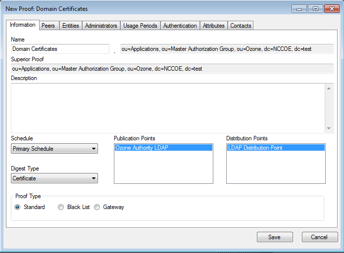
- Click the Administrators tab.
- Select the administrators to manage the proof.
- Click the Authentication tab.
- Click Add from file….
- Select the CA and intermediate CA certificates to be used to authenticate certificates retrieved.
- Select the Certificate Revocation Lists tab, as shown in Figure 13‑13.
- Enter the CRL Graceperiod, which is the number of hours that a CRL can be considered valid after its next update time.
- Click Add… to add a CRL.
Figure 13‑13 Ozone New Proof Authentication CRLs
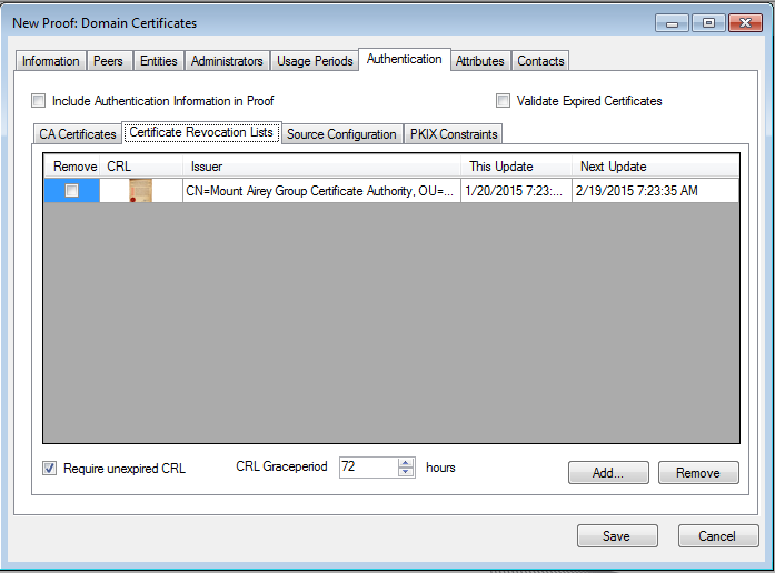
- Select the Source Configuration tab, as shown in Figure 13‑14.
- Enter the Hostname or IP Address of the LDAP server.
- Enter the Port Number on which the LDAP server is listening.
- Check the box for LDAPS.
- Enter the Entity base context of where user certificates can be obtained.
- Enter the Attribute Name for the certificates, either
userCertificateoruserCertificate;binary. - Enter the CRL Base Context of where updated CRLs can be obtained.
- Enter the CRL Attribute Name for the CRLs, typically
certificateRevocationList, as shown in Figure 13‑14. - Enter the connection information:
- If connecting anonymously, check the box for Connect Anonymously.
- If a Username and Password are required for the connection, enter them.
- Enter the number of hours after which Ozone Envoy should check the directory for new certificates.
Figure 13‑14 Ozone New Proof Authentication Source Configuration
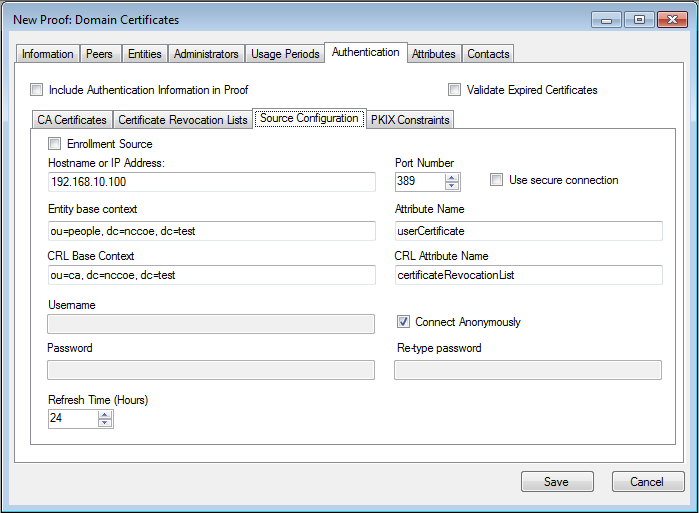
- Click Save.
Configure Ozone Authority to connect to Ozone Envoy:
- Select Enrollment > Envoy Configuration.
- Enter the Envoy Hostname or IP Address, as shown in Figure 13‑15.
- Enter the Port Number on which Ozone Envoy is listening.
- Enter the number of hours that should elapse between connections to Ozone Envoy to check for new information (Envoy Connection Intervals (Hours)).
- Enter the number of minutes that should elapse before attempting to reconnect to Ozone Envoy if the connection fails (Envoy Retry Interval (Minutes)).
- Click Save.
Figure 13‑15 Ozone Envoy Configuration
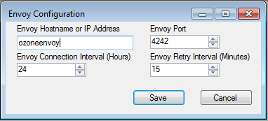
14. Physical Access Control: XTec XNode
The XNode was installed in the DMZ network. The XNode is a standalone IdAM demonstration capability that includes a personal identification verification (PIV) card reader, PIV Interoperable (PIV-I) cards, a keypad, and an electric door strike. The XNode was preconfigured to poll the IP address of the cloud‑based IdAM system at the XTec control center. No additional configuration information is required. The identities on the PIV cards each included the access‑allowed or access‑denied status, for demonstration purposes.
14.1. Security Characteristics
Cybersecurity Framework Categories: PR.AC-1: Identities and credentials are managed for authorized devices and users.
NIST SP 800-53 Revision 4 Security Controls: AC-2, IA Family, PE-2, PE-3, PE-4, PE-5, PE-6, PE-9
15. Enterprise Public-Key-Infrastructure Platform: GlobalSign
15.1. Overview
The NCCoE used the GlobalSign Enterprise Public Key Infrastructure (PKI) platform to issue and manage North American Energy Standards Board (NAESB) WEQ-12 digital certificates that are used for secure network access for both internal and external users (Figure 15‑1). The certificates were used in conjunction with the MAG Ozone product to provide high‑assurance attributes for the Personal Profile Application. The application has three main information groups for which actions can be authorized: Personal Information, Credit Reports, and Criminal History. Based on the authorizations associated with a credential, results pages are dynamically populated.
Figure 15‑1 GlobalSign Overview
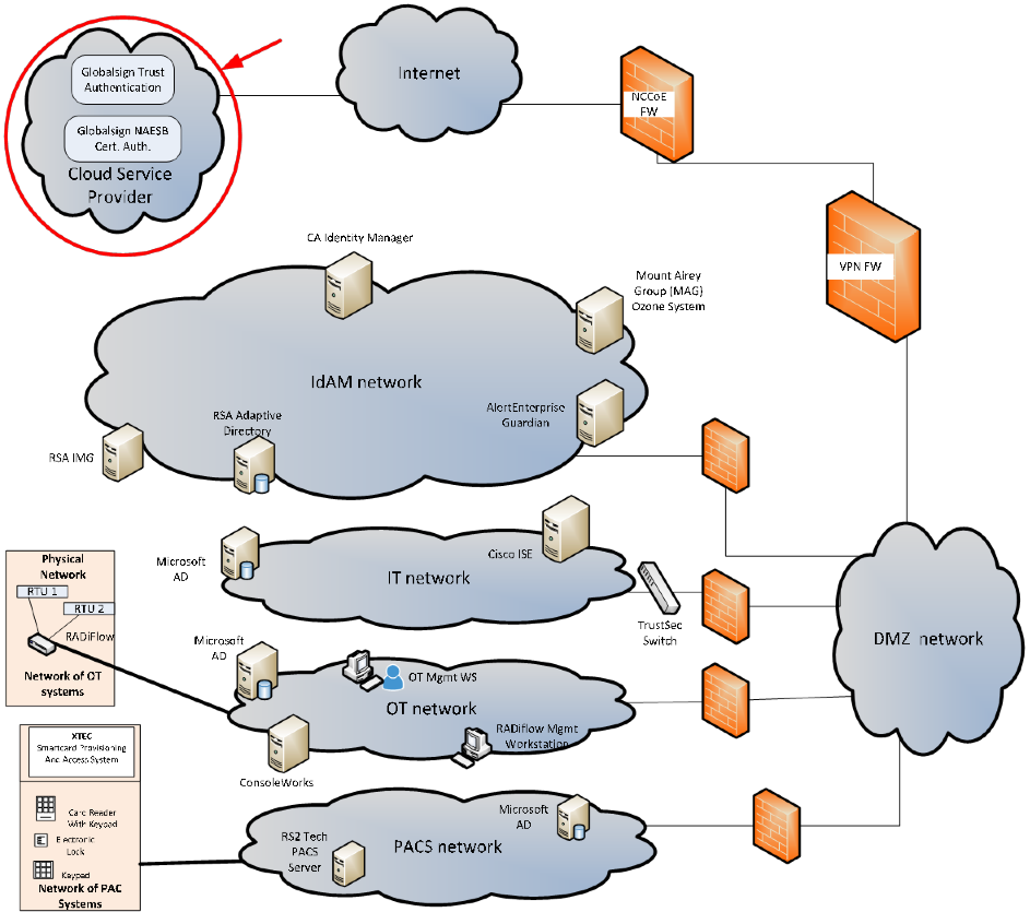
NAESB serves as an industry forum for the development and promotion of business process standards that can lead to a seamless marketplace for wholesale and retail natural gas and electricity, as recognized by its customers, business community, participants, and regulatory entities. GlobalSign is an active participant of the NAESB Cyber-Security standards committee and is an NAESB-authorized Certificate Authority (CA). For more information about NAESB, go to https://www.naesb.org/.
GlobalSign’s NAESB-compliant certificate-based authentication solution is managed through a software as a service (SaaS) that is accessed through a web-based portal. The web portal gives organizations control of digital IDs that are issued to individuals, by using one of four NIST‑defined assurance levels. Set-up usually takes fewer than three days. Another advantage of the web portal is that all of the life‑cycle functions, including issuance, re-issuance, renewal, and revocation, are available to the administrator.
15.1.1. Managing the Account
The account is managed using the GlobalSign Certificate Center (GCC). GCC is a web-based interface allowing members to access their certificates anywhere where they have an internet connection. Within the platform, administrators may add additional users and may delegate some or all certificate management functions.
15.1.2. What Is a Profile? / Profile Management
A profile, or certificate profile, contains the organization’s identity information that will be used for all NAESB WEQ-12 digital certificates issued from the account. Organization identity information includes the organization legal name, country code, and optionally locality, state, and up to three fixed organization units, as well as assurance level.
15.1.3. What Is a License?
GlobalSign NAESB digital certificates are sold in “license packs” (i.e., in quantities of 5, 10, 25, 50, etc.). GlobalSign NAESB digital certificates are valid for either one or two years, and must be issued within 12 months of license ordering.
15.2. Security Characteristics
Cybersecurity Framework Categories: PR.AC-1: Identities and credentials are managed for authorized devices and users.
NIST SP 800-53 Revision 4 Security Controls: AC-2, IA Family
15.3. How To Order Certificates
15.3.1. Step 1: Get a GlobalSign GCC Account
Request a GCC account at https://www.globalsign.com/en/verticals/energy/.
15.3.2. Step 2: Order Certificate License Pack
Once you have your GCC account credentials, use the following link to log in: www.globalsign.com/en/login/ (Figure 15‑2).
Figure 15‑2 GlobalSign Login Page
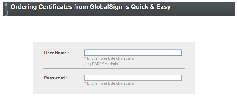
- Click on the ENTERPRISE PKI tab, as shown in Figure 15‑3.
Figure 15‑3 GlobalSign Enterprise PKI Tab

- Click Order Licenses from the left-side menu, as shown in Figure 15‑4.
Figure 15‑4 GlobalSign Order Licenses Page
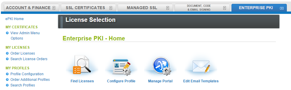
- Choose the Enterprise PKI Pro For Personal Digital ID license pack that you intend to purchase, and then click Next, as shown in Figure 15‑5.
Figure 15‑5 GlobalSign License Selection Page
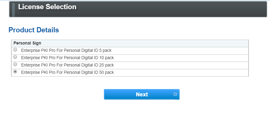
- Choose your validity period (one-year or two‑year certificate), as shown in Figure 15‑6.
Figure 15‑6 GlobalSign Product Details
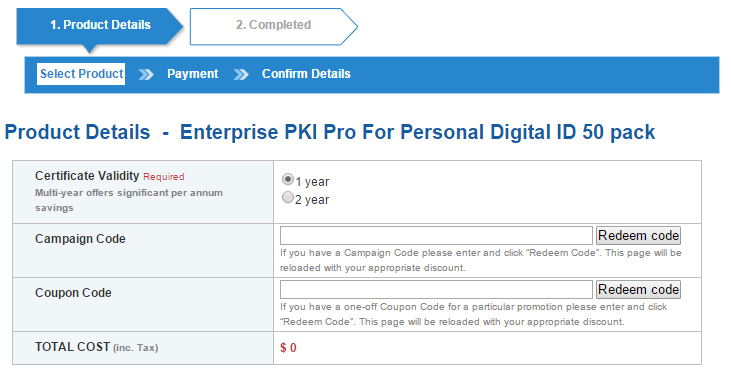
- Provide payment details, as shown in Figure 15‑7.
Figure 15‑7 GlobalSign Payment Details
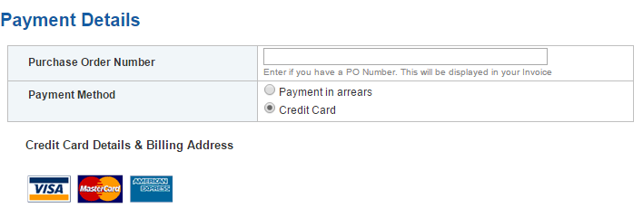
- Confirm your order details, and check the required box to confirm that you understand that the license pack will expire 12 months from the order date (Figure 15‑8).
Figure 15‑8 GlobalSign Confirm Details
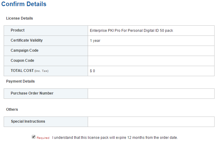
15.3.3. Step 3: Set Up Organization Profile
- Click Order Additional Profiles from the left navigation menu, as shown in Figure 15‑9.
Figure 15‑9 GlobalSign Order Additional Profiles
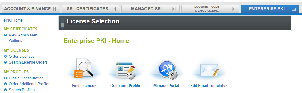
- Enter your Organization Profile details. Note that the details that you enter will be vetted and included as the certificate identity within your issued certificate (Figure 15‑10).
- Select the Assurance Level that is appropriate for the risk associated with the transaction (Figure 15‑10). Contact GlobalSign NAESB experts for additional guidance on this topic.
Figure 15‑10. GlobalSign Certificate Profile Details
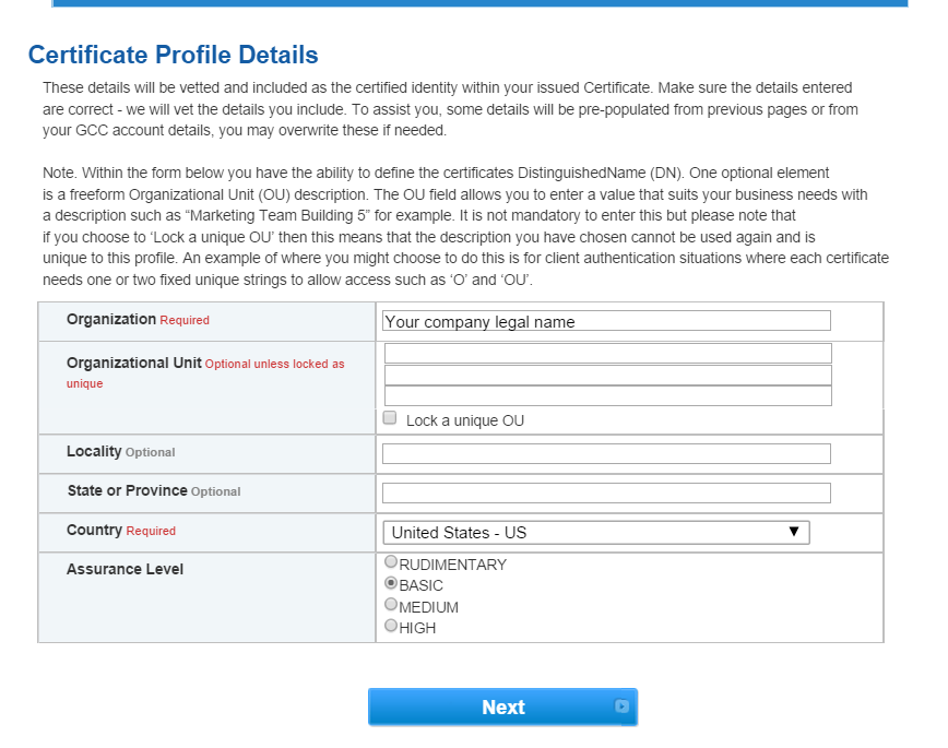
Confirm your profile details (Figure 15‑11), and then review and accept the EPKI Service Agreement, which includes important NAESB WEQ-012 obligations. Note that the EPKI Service Agreement binds you to obligations, as outlined in the GlobalSign Certificate Policy and Certificate Practice Statements, including Local Registration Authority, end user, and relying party, as defined in the NAESB PKI Standards – WEQ-012.
Certificate Practice Statements can be found at http://www.globalsign.com/repository/.
Figure 15‑11 GlobalSign Confirm Details
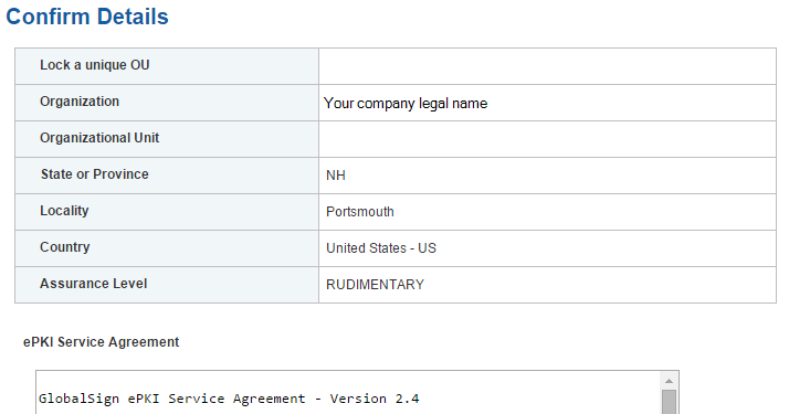
15.3.4. Step 4: Vetting
Once you have placed your order, all of your information will be sent to GlobalSign’s vetting department. The organization details that you provided for your profile will be vetted by GlobalSign, using third-party checks.
15.3.5. Step 5: Register for Your EPKI Administrator Certificate
Once your company profile has been approved, you will need to register for an EPKI Administrator Certificate. An EPKI Administrator Certificate is required for authentication to secure areas of the EPKI service to register and manage end‑user certificates.
- Log into GCC.
- Select View Admin Menu Options in the left-side menu to start the enrollment process (Figure 15‑12).
Figure 15‑12 GlobalSign View Admin Menu Options
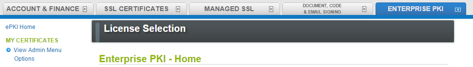
- Choose a certificate password. It is very important to remember this password.
- Download your administrator certificate, and follow the on-screen prompts to install your certificate.
- Follow the guide at http://www.globalsign.com/support/ordering-guides/epki-authentication-user-guide.pdf for step-by-step instructions on how to order, install, and use your Administrator Certificate.
CAUTION: If you need to access the EPKI administrator menu options from multiple machines, you can copy your .pfx file to other computers and repeat the import process. Instructions for importing your certificate can be found at https://support.globalsign.com/customer/portal/articles/1211387.
15.3.6. Step 6: Register and Issue Certificates to Individual Users
Click Order Certificates in the left-side menu, as shown in Figure 15‑13.
Note: If you haven’t already authenticated to the secure section of the portal with your Administrator Certificate, you may see View Admin Menu Options, instead of the menu options that are shown in Figure 15‑13. If this is the case, then click the View Admin Menu Options link, and then select the appropriate certificate to gain access to this section of the portal.
Figure 15‑13 GlobalSign Oder Certificates
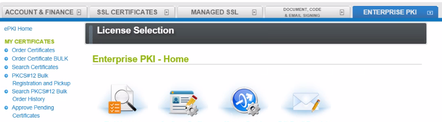
- Select the profile and license that you want to use, and then click Next (Figure 15‑14).
Figure 15‑14 GlobalSign Product Selection
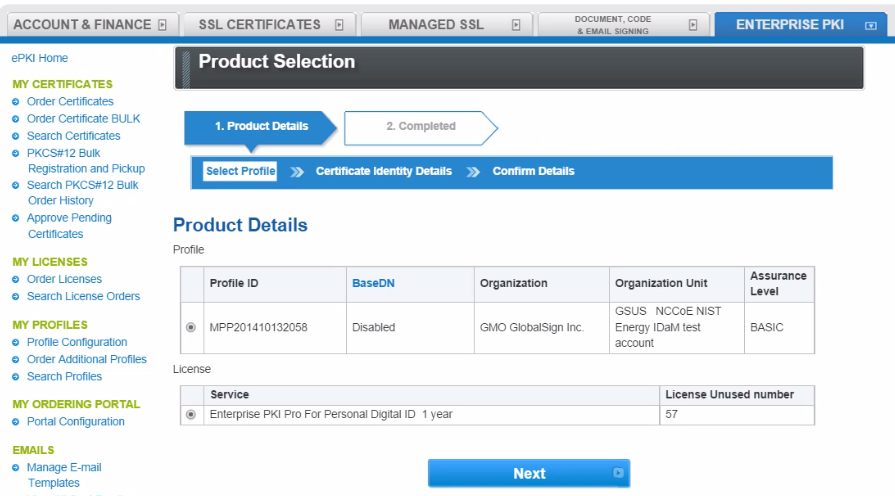
- Complete the Certificate Identity details (Figure 15‑15) for the end user of the certificate, including the Common Name (i.e., the individual’s first name and last name) and the Email Address. The organization name and other fields will be pre-populated from the profile that you selected.
Figure 15‑15 GlobalSign Certificate Identity Details
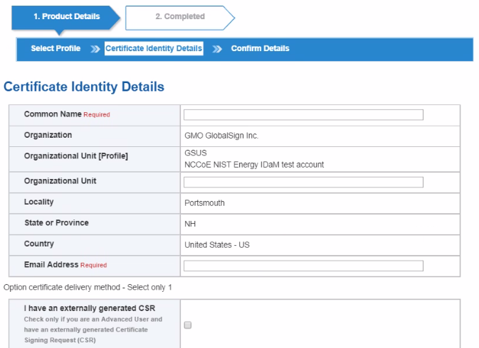
You will also need to choose a pick-up password. The pick-up password is a unique password that you will give to the end user of the certificate. After you have completed the registration process, the end user will receive an email invitation to pick up their certificate; at that time, the end user will be prompted for the pick-up password (you gave to them in an out-of-band method), and will be provided with details of how to install his/her new certificate.
- Finally, confirm the details of your certificate request, as shown in Figure 15‑16.
Figure 15‑16 GlobalSign Confirm Details
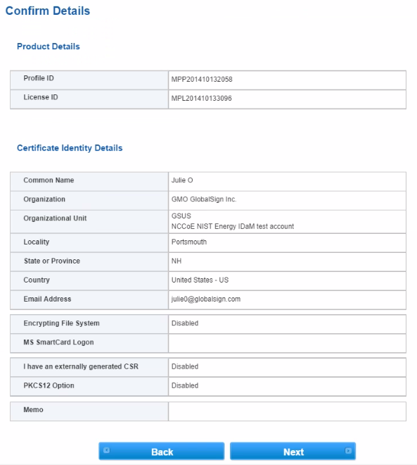
- Repeat this process until you have requested certificates for all of your end users.
For further information on the features available in the GlobalSign Certificate Center, see http://www.globalsign.com/support/ordering-guides/globalsign-epki-admin-guide.pdf.
15.4. GlobalSign’s Identity and Access Management Solution for Managing External Users
For use cases involving external users (e.g., Independent System Operators) operating wholesale electric marketplaces, GlobalSign PKI can provide an IdAM solution that enables the management of external user (customer and collaborator) identities, and the online services and applications that they can access.
15.5. Getting Help
GlobalSign provides technical support through its Client Service departments around the world. Visit https://support.globalsign.com/ for detailed instructions on installing and managing certificates, or contact support@globalsign.com or 1-877-467-7543 with specific questions.
16. Industrial Firewall: Schneider Electric
A Schneider Electric industrial firewall is installed on the physical network that contains the ICS/SCADA components that can be accessed and controlled via the OT network. The firewall is configured to monitor the data passing between the RADiFlow SCADA firewall and the OT network. The Schneider Electric industrial firewall will alert if out-of-policy traffic is detected on the network segment connecting the OT network and the SCADA network of devices.
To install and configure the Schneider Tofino firewall, follow these steps:
- Download the ConneXium software from the Schneider site, as stated in the instructions accompanying the firewall, and then start the ConneXium Tofino Configurator.
- In the startup screen, click Create New Project… (Figure 16‑1).
Figure 16‑1 Create New Project
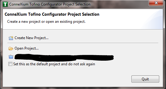
- In the Project name field, enter the name that you would like to use for the project, as shown in Figure 16‑2. Also fill in the Company field. When finished, click Next.
Figure 16‑2 New Project Wizard
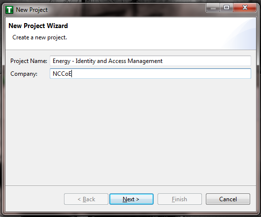
- In the Project Protection screen (Figure 16‑3), choose a password to protect the project, and then click Next.
Figure 16‑3 Project Protection
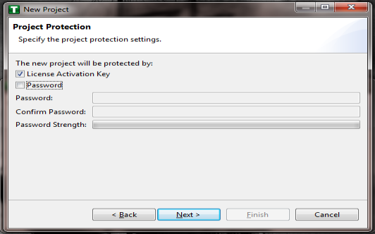
- In the Administrator Password screen (Figure 16‑4), choose the administrator password, and then click Finish.
Figure 16‑4 Administrator Password
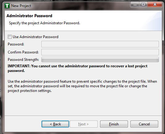
- In the Project Explorer Window (Figure 16‑5), right‑click Tofino SAs, and then click New Tofino SA.
Note: You can also choose to create a folder for the SAs to help organize multiple areas.
Figure 16‑5 Project Explorer Window
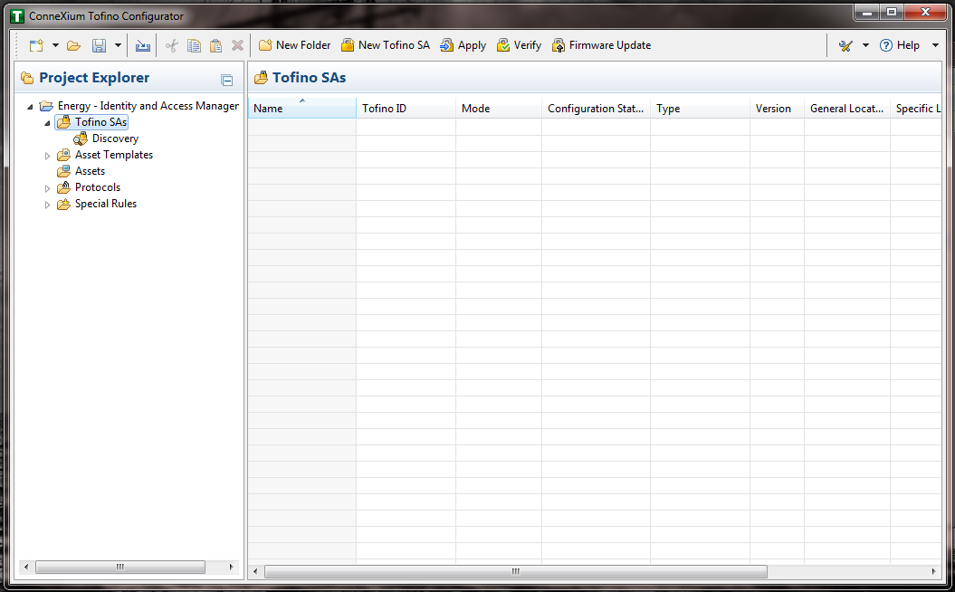
- In the Tofino ID field (Figure 16‑6), enter the MAC address listed on the firewall hardware sticker. Fill out the rest of the fields as necessary, and then click Finish.
Figure 16‑6 Tofino SA/MAC Address
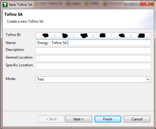
- Right-click on the Assets icon in the Project Explorer frame (Figure 16‑7), and then click New Asset.
Figure 16‑7 Project Explorer
- In the New Asset window (Figure 16‑8), set the Name of the device and the Type of the device. Complete all other necessary fields, and then click Next.
Figure 16‑8 New Asset
- Fill in the IP address and/or the MAC address fields (refer back to Figure 16‑6), and then click Finish.
- Repeat Steps 8 through 10 for all devices on the network. When all devices are configured, click the Assets icon in the Project Explorer frame (Figure 16‑9), if it is not already selected, and then there should be a list of all of the configured assets.
Figure 16‑9 Project Explorer Assets Icon
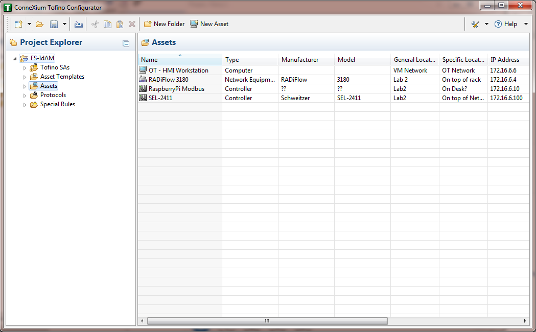
- Under the Project Explorer frame, click the drop-down arrow next to Tofino SAs, and then choose the SA that was created earlier (Figure 16‑10). From there, click Firewall in the Project Explorer frame to display the current firewall rules. This should be empty currently (Figure 16‑10).
Figure 16‑10 Project Explorer Tofino SA Icon
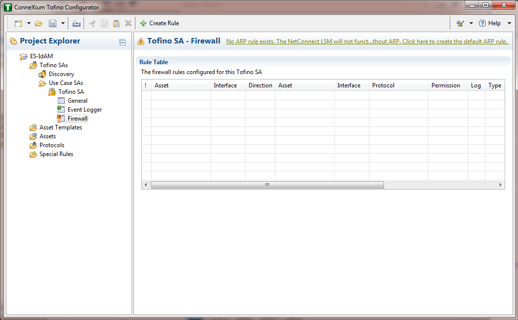
- To create the first rule, click the + Create Rule button above the Tofino SA – Firewall title (refer back to Figure 16‑6). Ensure that the Standard rule radio button is selected, and then click Next (Figure 16‑11).
Figure 16‑11 Rule Type
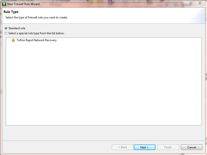
- On the next screen (Figure 16‑12), there a few options to determine. The first is Asset 1; you must choose the interface. This will be where the traffic is coming from into the device. In the Lab Build, Asset 1 is the OT Workstation, which is connected to a network that is connected to the External interface on the firewall. Select the Select an asset from the list below radio button for both Asset 1 and Asset 2, and then select the systems to create a rule between the assets. Also, select the direction of the traffic by using the arrow buttons in the middle of the screen, between the assets. When finished, select Next.
Figure 16‑12 Firewall Rule Wizard
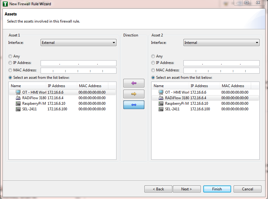
- On the Asset Rule Profiles (Figure 16‑13), select the Manually create the firewall rules for the selected assets radio button, and then click Next.
Figure 16‑13 Asset Rule Profiles
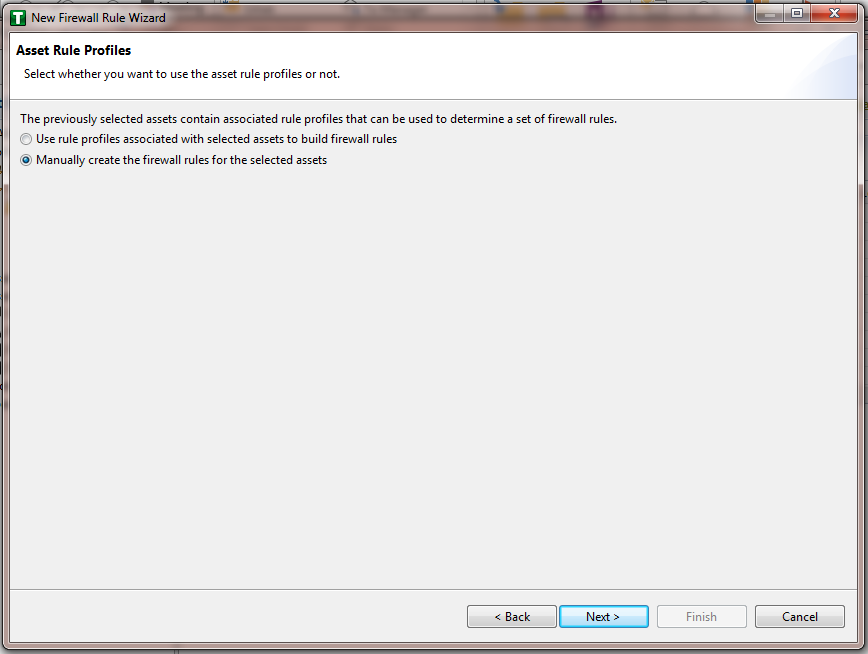
- On the Protocol screen (Figure 16‑14), choose the protocol to be checked against. There are drop‑down menus for Common Industrial, Common IT, and Vendor Specific. For this example, we are choosing SSH and Telnet (By holding the CTRL key, you can select multiple protocols.). Choose the permission on the right side of the screen, as well as whether or not to enable logging. Click Finish.
Figure 16‑14 Protocol Window
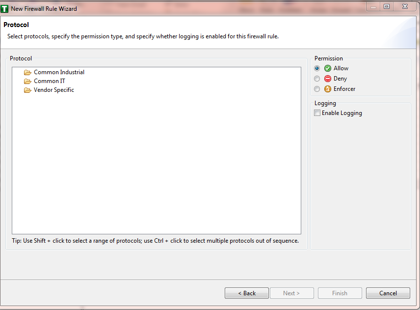
Note: By default, any traffic that does not match the rules in the firewall will automatically be denied.
After that is completed, the firewall rule should be listed in the Rule Table (Figure 16‑15).
Figure 16‑15 Rule Table
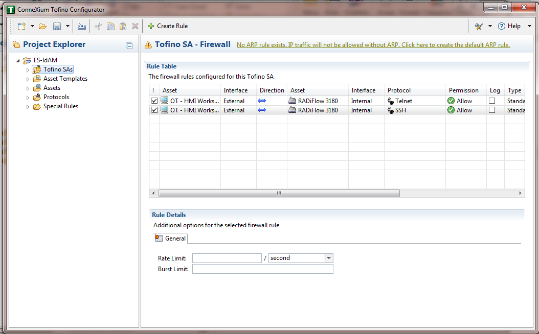
- Repeat Steps 13 through 17 for the remainder of the rules needed.
- Finally, click the save icon on the menu bar (circled in red below in Figure 16‑16).
Figure 16‑16 Save Rules in Project Explorer
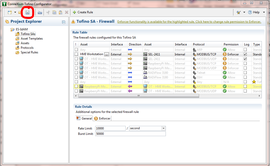
- Place a FAT/FAT32 formatted USB device into the computer running the ConneXium Tofino Configurator, right-click Tofino SAs in the Project Explorer pane, and then select Apply. If the project asks you to save, click OK.
Figure 16‑17 Apply Configuration Pane
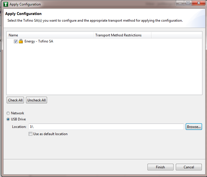
- In the Apply Configuration pane (Figure 16‑17), ensure that your SA is selected in the table at the top, and that the USB Drive radio button is selected. Browse to the top-level directory of your USB drive, and then click Finish.
- A popup window (Figure 16‑18) will notify you of successful completion.
Figure 16‑18 Loadable USB Drive Popup
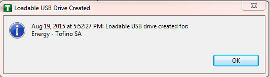
- Ensure that the firewall has been powered on and has been running for at least one minute, and then plug the USB device that was used to copy the Tofino configuration into the USB port on the back of the firewall.
- Press the Save/Load/Reset button twice, setting it to the Load setting (Pressing it once should turn the indicator light to green; pressing it again will change the indicator light from green to amber). After a few seconds, the device will begin displaying lights that move from right to left across the light-emitting diodes (LEDs) on the back, indicating that the configuration is being loaded.
- Once the lights stop moving from right to left, wait a few seconds, and ensure that the Fault LED does not light up. Remove the USB drive, and place it back into the computer running the ConneXium Tofino Configurator software.
- Right-click Tofino SAs in the Project Explorer pane, and then select Verify.
- At the Verify Loaded Configuration window, select the Tofino SA in the table, and then select the USB Drive radio button. Select the USB drive by using the Browse button. Finally, click Finish. A popup window will notify you of successful verification, and that configuration is complete.
17. Operating System STIG Compliance Reports
STIG compliance reports were generated for the STIG-compliant OS installations used in the build. The reports for each installation are provided in the following subsections. Neither the Windows 7 Console on the IT network nor the OT Management Windows 7 Workstation on the OT network were STIG-compliant installations; therefore, compliance reports for those OSs are not provided.
The Linux implementations (except SUSE Linux) were configured to meet the DoD CentOS 6 STIG, as no CentOS 7 STIG was available at the time the build was implemented. The STIG guidelines are available at http://iase.disa.mil/stigs/os/Pages/index.aspx. The OS configurations for each Linux implementation are listed below. The compliance results reports identify the configuration items that do not conform to the STIG configuration guide.
This section provides compliance reports for the following Oss:
- SQL Server on IdAM Network STIG Compliance Report
- RSA IMG SUSE Linux Server STIG Compliance Report
- RSA Adaptive Directory CentOS 7 Server STIG Compliance Report
- AlertEnterprise Microsoft Server STIG Compliance Report
- IT Domain Controller STIG Compliance Report
- IT Windows 7 Workstations STIG Compliance Report
- Ozone Authority and Ozone Server CentOS 6 Server STIG Compliance Report
- Ozone Envoy CentOS 6 Server STIG Compliance Report
- OT Domain Controller STIG Compliance Report
- OT ConsoleWorks Windows Server 2012 STIG Compliance Report
- OT Windows 7 Workstations STIG Compliance Report
- PACS Domain Controller STIG Compliance Report
- PACS Console Windows Server 2012 STIG Compliance Report
- Baseline CentOS 7 Linux Configuration
17.1. SQL Server on IdAM Network STIG Compliance Report
| Status | STIG ID | Rule ID | Vulnerability ID | Severity | Rule Title |
|---|---|---|---|---|---|
| N/A | SQL2-00-000300 | SV-53912r1_rule | V-41389 | CAT II | SQL Server must maintain and support organization-defined security labels on stored information. |
| N/A | SQL2-00-000400 | SV-53914r1_rule | V-41391 | CAT II | SQL Server must maintain and support organization-defined security labels on information in process. |
| N/A | SQL2-00-000500 | SV-53916r1_rule | V-41392 | CAT II | SQL Server must maintain and support organization-defined security labels on data in transmission. |
| N/A | SQL2-00-000900 | SV-53917r1_rule | V-41393 | CAT II | SQL Server must allow authorized users to associate security labels to information in the database. |
| N/A | SQL2-00-00920 | SV-53920r1_rule | V-41395 | CAT II | SQL Server must be protected from unauthorized access by developers. |
| N/A | SQL2-00-009300 | SV-53921r1_rule | V-41396 | CAT II | SQL Server must be protected from unauthorized access by developers on shared production/development host systems. |
| PASS | SQL2-00-00950 | SV-53922r2_rule | V-41397 | CAT II | Administrative privileges, built-in server roles, and built-in database roles must be assigned to the DBMS login accounts that require them via custom roles, and not directly. |
| PASS | SQL2-00-011050 | SV-53918r2_rule | V-41394 | CAT II | SQL Server utilizing Discretionary Access Control (DAC) must enforce a policy that limits propagation of access rights. |
UNKNOWN What is considered auditable? |
SQL2-00-011200 | SV-53928r2_rule | V-41402 | CAT II | SQL Server must provide an audit‑record-generation capability for organization-defined auditable events within the database. |
17.2. RSA IMG SUSE Linux Server STIG Compliance Report
OpenSCAP Evaluation Report
17.2.1. Evaluation Characteristics
- Target machine: dvd-acm
- Benchmark URL: U_RedHat_6_V1R6_STIG_SCAP_1-1_Benchmark-xccdf.xml
- Performed by: root
17.2.2. Compliance and Scoring
The target system did not satisfy the conditions of 107 rules! Furthermore, the results of 12 rules were inconclusive. Please review the rule results (Section 17.2.3) and consider applying remediation.
17.2.3. Rule Results
- Passed: 60 rules
- Failed: 107 rules
- Other: 12 rules
17.2.4. Severity of Failed Rules
- Other: 0 rules
- Low: 53 rules
- Medium: 53 rules
- High: 1 rule
17.2.5. Score
| System | Score | Maximum Score | Score as Percentage | Bar |
|---|---|---|---|---|
| urn:xccdf:scoring:default | 33.519554 | 100.000000 | 33.52% |
Search
| Title | Severity | Result |
|---|---|---|
| Red Hat Enterprise Linux 6 Security Technical Implementation Guide 107x fail 12x error | ||
| SRG-OS-999999 1x error | ||
| Automated file system mounting tools must not be enabled unless needed. | low | error |
| SRG-OS-000062 1x fail | ||
| Auditing must be enabled at boot by setting a kernel parameter. | low | fail |
| SRG-OS-999999 1x fail | ||
| The /etc/gshadow file must be owned by root. | medium | fail |
| SRG-OS-999999 1x fail | ||
| The /etc/gshadow file must be group-owned by root. | medium | fail |
| SRG-OS-999999 1x fail | ||
| The /etc/gshadow file must have mode 0000. | medium | fail |
| SRG-OS-999999 1x fail | ||
| The system must use a separate file system for /tmp. | low | fail |
| SRG-OS-999999 1x fail | ||
| The system must use a separate file system for /var. | low | fail |
| SRG-OS-999999 1x fail | ||
| The system must use a separate file system for /var/log. | low | fail |
| SRG-OS-000259 1x fail | ||
| Library files must be owned by root. | medium | fail |
| SRG-OS-000044 1x fail | ||
| The system must use a separate file system for the system audit data path. | low | fail |
| SRG-OS-000045 1x fail | ||
| The audit system must alert designated staff members when the audit storage volume approaches capacity. | medium | fail |
| SRG-OS-000259 1x fail | ||
| All system command files must be owned by root. | medium | fail |
| SRG-OS-999999 1x fail | ||
| The system must use a separate file system for user home directories. | low | fail |
| SRG-OS-000078 1x fail | ||
| The system must require passwords to contain a minimum of 14 characters. | medium | fail |
| SRG-OS-000075 1x fail | ||
| Users must not be able to change passwords more than once every 24 hours. | medium | fail |
| SRG-OS-000076 1x fail | ||
| User passwords must be changed at least every 60 days. | medium | fail |
| SRG-OS-000071 1x fail | ||
| The system must require passwords to contain at least one numeric character. | low | fail |
| SRG-OS-000103 1x fail | ||
| The system package management tool must cryptographically verify the authenticity of system software packages during installation. | medium | fail |
| SRG-OS-000232 1x fail | ||
| A file integrity tool must be installed. | medium | fail |
| SRG-OS-000273 1x fail | ||
| The operating system must enforce requirements for the connection of mobile devices to operating systems. | medium | fail |
| SRG-OS-000248 1x fail | ||
| There must be no .rhosts or hosts.equiv files on the system. | high | fail |
| SRG-OS-000249 1x fail | ||
| The system must disable accounts after excessive login failures within a 15-minute interval. | medium | fail |
| SRG-OS-999999 1x fail | ||
| The /etc/shadow file must be group-owned by root. | medium | fail |
| SRG-OS-999999 1x fail | ||
| The /etc/shadow file must have mode 0000. | medium | fail |
| SRG-OS-999999 1x fail | ||
| IP forwarding for IPv4 must not be enabled, unless the system is a router. | medium | fail |
| SRG-OS-000146 1x error | ||
| The operating system must prevent public IPv4 access into an organizations internal networks, except as appropriately mediated by managed interfaces employing boundary protection devices. | medium | error |
| SRG-OS-000231 1x fail | ||
| The systems local IPv4 firewall must implement a deny-all, allow-by-exception policy for inbound packets. | medium | fail |
| SRG-OS-000096 1x fail | ||
| The Datagram Congestion Control Protocol (DCCP) must be disabled unless required. | medium | fail |
| SRG-OS-000096 1x fail | ||
| The Stream Control Transmission Protocol (SCTP) must be disabled unless required. | medium | fail |
| SRG-OS-000096 1x fail | ||
| The Reliable Datagram Sockets (RDS) protocol must be disabled unless required. | low | fail |
| SRG-OS-000096 1x fail | ||
| The Transparent Inter-Process Communication (TIPC) protocol must be disabled unless required. | medium | fail |
| SRG-OS-000215 1x fail | ||
| The operating system must back up audit records on an organization‑defined frequency, onto a different system or media than the system being audited. | medium | fail |
| SRG-OS-000043 1x fail | ||
| The operating system must support the requirement to centrally manage the content of audit records generated by organization‑defined information system components. | medium | fail |
| SRG-OS-000062 1x fail | ||
| The audit system must be configured to audit all attempts to alter system time through settimeofday. | low | fail |
| SRG-OS-999999 1x fail | ||
| The system must not accept IPv4 source-routed packets on any interface. | medium | fail |
| SRG-OS-999999 1x fail | ||
| The system must not accept ICMPv4 redirect packets on any interface. | medium | fail |
| SRG-OS-999999 1x fail | ||
| The system must not accept ICMPv4 secure redirect packets on any interface. | medium | fail |
| SRG-OS-000062 1x fail | ||
| The audit system must be configured to audit all attempts to alter system time through clock_settime. | low | fail |
| SRG-OS-999999 1x fail | ||
| The system must log Martian packets. | low | fail |
| SRG-OS-999999 1x fail | ||
| The system must not accept IPv4 source-routed packets by default. | medium | fail |
| SRG-OS-000062 1x fail | ||
| The audit system must be configured to audit all attempts to alter system time through /etc/localtime. | low | fail |
| SRG-OS-000004 1x fail | ||
| The operating system must automatically audit account creation. | low | fail |
| SRG-OS-999999 1x fail | ||
| The system must not accept ICMPv4 secure redirect packets by default. | medium | fail |
| SRG-OS-999999 1x fail | ||
| The system must ignore ICMPv4 redirect messages by default. | low | fail |
| SRG-OS-000239 1x fail | ||
| The operating system must automatically audit account modification. | low | fail |
| SRG-OS-999999 | ||
| The system must not respond to ICMPv4 sent to a broadcast address. | low | pass |
| SRG-OS-000240 1x fail | ||
| The operating system must automatically audit account disabling actions. | low | fail |
| SRG-OS-999999 1x fail | ||
| The system must ignore ICMPv4 bogus error responses. | low | fail |
| SRG-OS-000241 1x fail | ||
| The operating system must automatically audit account termination. | low | fail |
| SRG-OS-000142 1x fail | ||
| The system must be configured to use TCP syncookies. | medium | fail |
| SRG-OS-999999 1x fail | ||
| The audit system must be configured to audit modifications to the systems Mandatory Access Control (MAC) configuration (SELinux). | low | fail |
| SRG-OS-000064 1x fail | ||
| The audit system must be configured to audit all discretionary access‑control permission modifications using chmod. | low | fail |
| SRG-OS-999999 1x fail | ||
| The system must use a reverse-path filter for IPv4 network traffic when possible by default. | medium | fail |
| SRG-OS-000064 1x fail | ||
| The audit system must be configured to audit all discretionary access‑control permission modifications using chown. | low | fail |
| SRG-OS-999999 1x fail | ||
| The IPv6 protocol handler must not be bound to the network stack unless needed. | medium | fail |
| SRG-OS-000064 1x fail | ||
| The audit system must be configured to audit all discretionary access-control permission modifications using fchmod. | low | fail |
| SRG-OS-999999 1x fail | ||
| The system must ignore ICMPv6 redirects by default. | medium | fail |
| SRG-OS-000064 1x fail | ||
| The audit system must be configured to audit all discretionary access-control permission modifications using fchmodat. | low | fail |
| SRG-OS-000064 1x fail | ||
| The audit system must be configured to audit all discretionary access-control permission modifications using fchown. | low | fail |
| SRG-OS-000064 1x fail | ||
| The audit system must be configured to audit all discretionary access-control permission modifications using fchownat. | low | fail |
| SRG-OS-000152 1x error | ||
| The system must employ a local IPv4 firewall. | medium | error |
| SRG-OS-000064 1x fail | ||
| The audit system must be configured to audit all discretionary access-control permission modifications using fremovexattr. | low | fail |
| SRG-OS-000064 1x fail | ||
| The audit system must be configured to audit all discretionary access-control permission modifications using fsetxattr. | low | fail |
| SRG-OS-000064 1x fail | ||
| The audit system must be configured to audit all discretionary access-control permission modifications using lchown. | low | fail |
| SRG-OS-000064 1x fail | ||
| The audit system must be configured to audit all discretionary access-control permission modifications using lremovexattr. | low | fail |
| SRG-OS-000064 1x fail | ||
| The audit system must be configured to audit all discretionary access-control permission modifications using lsetxattr. | low | fail |
| SRG-OS-000064 1x fail | ||
| The audit system must be configured to audit all discretionary access-control permission modifications using removexattr. | low | fail |
| SRG-OS-000064 1x fail | ||
| The audit system must be configured to audit all discretionary access-control permission modifications using setxattr. | low | fail |
| SRG-OS-000064 1x fail | ||
| The audit system must be configured to audit successful file system mounts. | low | fail |
| SRG-OS-000069 1x fail | ||
| The system must require passwords to contain at least one uppercase alphabetic character. | low | fail |
| SRG-OS-000266 1x fail | ||
| The system must require passwords to contain at least one special character. | low | fail |
| SRG-OS-000070 1x fail | ||
| The system must require passwords to contain at least one lowercase alphabetic character. | low | fail |
| SRG-OS-000072 1x fail | ||
| The system must require at least four characters be changed between the old and new passwords during a password change. | low | fail |
| SRG-OS-000021 1x fail | ||
| The system must disable accounts after three consecutive unsuccessful logon attempts. | medium | fail |
| SRG-OS-000120 1x fail | ||
| The system must use a FIPS 140-2 approved cryptographic hashing algorithm for generating account password hashes (system-auth). | medium | fail |
| SRG-OS-000064 1x fail | ||
| The audit system must be configured to audit user deletions of files and programs. | low | fail |
| SRG-OS-000120 1x fail | ||
| The system must use a FIPS 140-2 approved cryptographic hashing algorithm for generating account password hashes (login.defs). | medium | fail |
| SRG-OS-000120 1x fail | ||
| The system must use a FIPS 140-2 approved cryptographic hashing algorithm for generating account password hashes (libuser.conf). | medium | fail |
| SRG-OS-000064 1x fail | ||
| The audit system must be configured to audit changes to the /etc/sudoers file. | low | fail |
| SRG-OS-999999 1x fail | ||
| The system boot loader configuration file(s) must be owned by root. | medium | fail |
| SRG-OS-000064 1x fail | ||
| The audit system must be configured to audit the loading and unloading of dynamic kernel modules. | medium | fail |
| SRG-OS-999999 1x fail | ||
| The system boot loader configuration file(s) must be group-owned by root. | medium | fail |
| SRG-OS-000096 1x error | ||
| The xinetd service must be disabled if no network services utilizing it are enabled. | medium | error |
| SRG-OS-999999 1x fail | ||
| The system boot loader configuration file(s) must have mode 0600 or less permissive. | medium | fail |
| SRG-OS-000096 1x fail | ||
| The xinetd service must be uninstalled if no network services utilizing it are enabled. | low | fail |
| SRG-OS-000080 1x fail | ||
| The system boot loader must require authentication. | medium | fail |
| SRG-OS-000080 1x fail | ||
| The system must require authentication upon booting into single-user and maintenance modes. | medium | fail |
| SRG-OS-000080 1x fail | ||
| The system must not permit interactive boot. | medium | fail |
| SRG-OS-000022 1x fail | ||
| The system must require administrator action to unlock an account locked by excessive failed login attempts. | medium | fail |
| SRG-OS-999999 1x fail | ||
| The system must not send ICMPv4 redirects by default. | medium | fail |
| SRG-OS-999999 1x fail | ||
| The system must not send ICMPv4 redirects from any interface. | medium | fail |
| SRG-OS-000096 1x error | ||
| The ypbind service must not be running. | medium | error |
| SRG-OS-999999 1x fail | ||
| The cron service must be running. | medium | fail |
| SRG-OS-999999 1x error | ||
| The avahi service must be disabled. | low | error |
| SRG-OS-000056 1x error | ||
| The system clock must be synchronized continuously, or at least daily. | medium | error |
| SRG-OS-999999 1x fail | ||
| The system must set a maximum audit log file size. | medium | fail |
| SRG-OS-000062 1x fail | ||
| The audit system must be configured to audit all attempts to alter system time through adjtimex. | low | fail |
| SRG-OS-999999 1x fail | ||
| The system must retain enough rotated audit logs to cover the required log retention period. | medium | fail |
| SRG-OS-000096 1x error | ||
| The atd service must be disabled. | low | error |
| SRG-OS-999999 1x fail | ||
| The system default umask for daemons must be 027 or 022. | low | fail |
| SRG-OS-999999 1x fail | ||
| The system default umask in /etc/login.defs must be 077. | low | fail |
| SRG-OS-999999 1x fail | ||
| The system default umask in /etc/profile must be 077. | low | fail |
| SRG-OS-999999 1x fail | ||
| The system default umask for the csh shell must be 077. | low | fail |
| SRG-OS-000096 1x error | ||
| The rdisc service must not be running. | low | error |
| SRG-OS-999999 1x fail | ||
| The system default umask for the bash shell must be 077. | low | fail |
| SRG-OS-999999 1x error | ||
| The postfix service must be enabled for mail delivery. | low | error |
| SRG-OS-000096 1x error | ||
| The netconsole service must be disabled unless required. | low | error |
| SRG-OS-000248 1x fail | ||
| X Windows must not be enabled unless required. | medium | fail |
| SRG-OS-999999 1x fail | ||
| Process core dumps must be disabled unless needed. | low | fail |
| SRG-OS-000027 1x fail | ||
| The system must limit users to 10 simultaneous system logins, or a site-defined number, in accordance with operational requirements. | low | fail |
| SRG-OS-000160 1x fail | ||
| The system must provide VPN connectivity for communications over untrusted networks. | low | fail |
| SRG-OS-000024 1x fail | ||
| A login banner must be displayed immediately prior to, or as part of, graphical desktop environment login prompts. | medium | fail |
| SRG-OS-000034 1x error | ||
| The Bluetooth service must be disabled. | medium | error |
| GEN006660 1x fail | ||
| Accounts must be locked upon 35 days of inactivity. | low | fail |
| SRG-OS-000118 1x fail | ||
| The operating system must manage information system identifiers for users and devices by disabling the user identifier after an organization defined time period of inactivity. | low | fail |
| SRG-OS-999999 1x fail | ||
| All public directories must be owned by a system account. | low | fail |
| SRG-OS-999999 1x fail | ||
| The system must use a Linux Security Module configured to enforce limits on system services. | medium | fail |
| SRG-OS-999999 1x fail | ||
| The system must use a Linux Security Module configured to limit the privileges of system services. | low | fail |
| SRG-OS-999999 1x fail | ||
| The operating system, upon successful logon/access, must display to the user the number of unsuccessful logon/access attempts since the last successful logon/access. | medium | fail |
| SRG-OS-999999 1x fail | ||
| The audit system must switch the system to single-user mode when available audit storage volume becomes dangerously low. | medium | fail |
17.3. RSA Adaptive Directory CentOS 7 Server STIG Compliance Report
XCCDF Test Result
Introduction
17.3.1. Test Result
| Result ID | Profile | Start Time | End Time | Benchmark | Benchmark Version |
|---|---|---|---|---|---|
| xccdf_org.open-scap_testresult_default-profile | (Default profile) | 2015-04-08 08:16 | 2015-04-08 08:17 | embedded | 1 |
17.3.2. Target Information
| Target | Addresses | Platform |
|---|---|---|
| adaptivedir |
|
cpe:/o:redhat:enterprise_linux:6 |
17.3.3. Score
| System | Score | Maximum Score | Score as Percentage | Bar |
|---|---|---|---|---|
| urn:xccdf:scoring:default | 96.65 | 100.00 | 96.65% |
17.3.4. Rule Results Summary
| Pass | Fixed | Fail | Error | Not Selected | Not Checked | Not Applicable | Inform-ational | Unknown | Total |
|---|---|---|---|---|---|---|---|---|---|
| 173 | 0 | 6 | 0 | 0 | 0 | 0 | 0 | 0 | 179 |
| Title | Result |
|---|---|
| Auditing must be enabled at boot by setting a kernel parameter. | fail |
| The audit system must be configured to audit modifications to the systems Mandatory Access Control (MAC) configuration (SELinux). | fail |
| The system boot loader configuration file(s) must be owned by root. | fail |
| The system boot loader configuration file(s) must be group-owned by root. | fail |
| The system boot loader configuration file(s) must have mode 0600 or less permissive. | fail |
| The system boot loader must require authentication. | fail |
17.4. AlertEnterprise Microsoft Server STIG Compliance Report
Non-Compliance Report – U_Windows_2008_R2_MS_V1R15_STIG_SCAP_1-0_Benchmark
SCAP Compliance Checker – 3.1.2
17.4.1. Score
| 30.04% |
|
|
|
17.4.2. System Information
| Target | WIN-IPERGL2ELUD |
| Operating System | Windows Server 2008 R2 Standard |
| OS Service Pack | |
| Domain |
17.4.3. Results
Unsupported Service Packs
- Systems must be at supported service pack or release levels. – Fail
Legal Notice Display
- The required legal notice will be configured to display before console logon. – (CCE-10673-2) – Fail
Caching of logon credentials
- Caching of logon credentials will be limited. – (CCE-10926-4) – Fail
Anonymous shares are not restricted
- Anonymous enumeration of shares will be restricted. – (CCE-10557-7) – Fail
Bad Logon Attempts
- The number of allowed bad-logon attempts will meet minimum requirements. – (CCE-11046-0) – Fail
Bad Logon Counter Reset
- The time before the bad-logon counter is reset will meet minimum requirements. – (CCE-11059-3) – Fail
Lockout Duration
- The lockout duration will meet minimum requirements. – (CCE-10399-4) – Fail
Rename Built-in Guest Account
- The built-in guest account will be renamed. – (CCE-10747-4) – Fail
Rename Built-in Administrator Account
- The built-in administrator account will be renamed. – (CCE-10976-9) – Fail
LanMan Authentication Level
- The LanMan authentication level will be set to Send NTLMv2 response only \ refuse LM & NTLM. – (CCE-10984-3) – Fail
Deny Access from the Network
- The deny access to this computer from the network user right on member servers must be configured to prevent access from highly privileged domain accounts and local administrator accounts on domain systems and unauthenticated access on all systems. – (CCE-10733-4) – Fail
Smart Card Removal Option
- The smart card removal option will be configured to Force Logoff or Lock Workstation. – (CCE-10573-4) – Fail
Format and Eject Removable Media
- Ejection of removable NTFS media is not restricted to Administrators. – (CCE-10637-7) – Fail
Password Expiration Warning
- Users will be warned in advance that their passwords will expire. – (CCE-10930-6) – Fail
Disable Media Autoplay
- Autoplay will be disabled for all drives. – (CCE-11126-0) – Fail
Anonymous Access to Named Pipes
- Named pipes that can be accessed anonymously will be configured to contain no values. –(CCE-10944-7) – Fail
Remote Assistance – Solicit Remote Assistance
- Solicited Remote Assistance will not be allowed. – (CCE-11723-4) – Fail
Undock Without Logging On
- A system must be logged onto before removing from a docking station. – (CCE-10883-7) – Fail
Storage of Passwords and Credentials
- The system will be configured to prevent the storage of passwords and credentials – (CCE-10292-1) – Fail
Force Logoff When Logon Hours Expire
- The system will be configured to force users to log off when their allowed logon hours expire. – (CCE-10588-2) – Fail
Session Security for NTLM SSP Based Clients
- The system will be configured to meet the minimum session security requirement for NTLM SSP based clients. – (CCE-10035-4) – Fail
FIPS Compliant Algorithms
- The system will be configured to use FIPS-compliant algorithms for encryption, hashing, and signing. – (CCE-10789-6) – Fail
TS/RDS – Session Limit
- Remote Desktop Services will limit users to one remote session. – (CCE-12016-2) – Fail
TS/RDS – Password Prompting
- Remote Desktop Services will always prompt a client for passwords upon connection. – (CCE-11299-5) – Fail
TS/RDS – Set Encryption Level
- Remote Desktop Services will be configured with the client connection encryption set to the required level. – (CCE-11677-2) – Fail
TS/RDS – Do Not Use Temp Folders
- Remote Desktop Services will be configured to use session-specific temporary folders. – (CCE-10669-0) – Fail
TS/RDS – Delete Temp Folders
- Remote Desktop Services will delete temporary folders when a session is terminated. – (CCE-12046-9) – Fail
TS/RDS – Time Limit for Disc. Session
- Remote Desktop Services will be configured to set a time limit for disconnected sessions. – (CCE-11117-9) – Fail
TS/RDS – Time Limit for Idle Session
- Remote Desktop Services will be configured to disconnect an idle session after the specified time period. – (CCE-11506-3) – Fail
Remote Assistance – Offer Remote Assistance
- The system will be configured to prevent unsolicited remote assistance offers. – (CCE-11625-1) – Fail
Error Reporting – Report Errors
- The system will be configured to prevent automatic forwarding of error information. – (CCE-11750-7) – Fail
Safe DLL Search Mode
- The system will be configured to use Safe DLL Search Mode. – (CCE-10772-2) – Fail
Media Player – Disable Automatic Updates
- Media Player must be configured to prevent automatic checking for updates. – (CCE-11298-7) – Fail
Session Security for NTLM SSP based Servers
- The system will be configured to meet the minimum session security requirement for NTLM SSP based servers. – (CCE-10040-4) – Fail
Audit Log Warning Level
- The system will generate an audit event when the audit log reaches a percent full threshold. – (CCE-11011-4) – Fail
Disable IP Source Routing
- The system will be configured to prevent IP source routing. – (CCE-10732-6) – Fail
Disable ICMP Redirect
- The system will be configured to prevent ICMP redirects from overriding OSPF generated routes. – (CCE-10518-9) – Fail
Disable Router Discovery
- The system will be configured to disable the Internet Router Discover Protocol (IRDP). – (CCE-10768-0) – Fail
TCP Connection Keep-Alive Time
- The system will be configured to limit how often keep-alive packets are sent. – (CCE-10381-2) – Fail
Name-Release Attacks
- The system will be configured to ignore NetBIOS name release requests except from WINS servers. – (CCE-10653-4) – Fail
TCP Data Retransmissions
- The system will limit how many times unacknowledged TCP data is retransmitted. – (CCE-10941-3) – Fail
Screen Saver Grace Period
- The system will be configured to have password protection take effect within a limited timeframe when the screen saver becomes active. – (CCE-10019-8) – Fail
Remotely Accessible Registry Paths and Sub-Paths
- Unauthorized remotely accessible registry paths and sub-paths will not be configured. – (CCE-10935-5) – Fail
Strong Key Protection
- Users will be required to enter a password to access private keys. – (CCE-11035-3) – Fail
Optional Subsystems
- Optional subsystems will not be permitted to operate on the system. – (CCE-10913-2) – Fail
Software Restriction Policies
- Software certificate restriction policies will be enforced. – (CCE-10900-9) – Fail
TS/RDS – Secure RPC Connection.
- The Remote Desktop Session Host will require secure RPC communications. – (CCE-11368-8) – Fail
Group Policy – Registry Policy Processing
- Group Policy objects will be reprocessed even if they have not changed. – (CCE-12754-8) – Fail
SMB Client Packet Signing (Always)
- The Windows SMB client will be enabled to always perform SMB packet signing. – (CCE-10970-2) – Fail
Minimum Password Length
- For systems utilizing a logon ID as the individual identifier, passwords will, at a minimum, be 14 characters. – (CCE-10372-1) – Fail
Display of Last Username
- The system will be configured to prevent the display of the last username on the logon screen. – (CCE-10788-8) – Fail
Audit Policy Subcategory Setting
- Audit policy using subcategories will be enabled. – (CCE-10112-1) – Fail
IPSec Exemptions
- IPSec exemptions will be limited. – (CCE-10018-0) – Fail
UAC – Admin Approval Mode
- User Account Control approval mode for the built-in administrator will be enabled. – (CCE-11028-8) – Fail
UAC – Admin Elevation Prompt
- User Account Control will, at a minimum, prompt administrators for consent. – (CCE-11023-9) – Fail
UAC – User Elevation Prompt
- User Account Control will automatically deny standard user requests for elevation. – (CCE-10807-6) – Fail
Enumerate Administrator Accounts on Elevation
- The system will require a username and password to elevate a running application. – (CCE-11450-4) – Fail
TS/RDS – Prevent Password Saving
- Passwords will not be saved in the Remote Desktop Client. – (CCE-11905-7) – Fail
TS/RDS – Drive Redirection
- Local drives will be prevented from sharing with Remote Desktop Session Hosts (Remote Desktop Services Role). – (CCE-11709-3) – Fail
RPC – Unauthenticated RPC Clients
- Unauthenticated RPC clients will be restricted from connecting to the RPC server. – (CCE-10881-1) – Fail
RPC – Endpoint Mapper Authentication
- Client computers will be required to authenticate for RPC communication. – (CCE-10715-1) – Fail
Internet Download / Online Ordering
- Web publishing and online ordering wizards will be prevented from downloading a list of providers. – (CCE-11136-9) – Fail
Printing Over HTTP
- Printing over HTTP will be prevented. – (CCE-11360-5) – Fail
HTTP Printer Drivers
- Downloading print driver packages over HTTP will be prevented. – (CCE-11563-4) – Fail
Windows Update Device Drive Searching
- Windows will be prevented from using Windows Update to search for drivers. – (CCE-10357-2) – Fail
IPv6 Transition
- IPv6 will be disabled until a deliberate transition strategy has been implemented. – Fail
Windows Peer to Peer Networking
- Windows Peer-to-Peer networking services will be turned off. – (CCE-11604-6) – Fail
Prohibit Network Bridge
- Network Bridges will be prohibited in Windows. – (CCE-12074-1) – Fail
Root Certificates Update
- Root Certificates will not be updated automatically from the Microsoft site. – (CCE-11264-9) – Fail
Event Viewer Events.asp Links
- Event Viewer Events.asp links will be turned off. – (CCE-10693-0) – Fail
Internet File Association Service
- The Internet File Association service will be turned off. – (CCE-10697-1) – Fail
Order Prints Online
- The Order Prints Online wizard will be turned off. – (CCE-11243-3) – Fail
Classic Logon
- The classic logon screen will be required for user logons. – (CCE-11256-5) – Fail
RSS Attachment Downloads
- Attachments will be prevented from being downloaded from RSS feeds. – Fail
Windows Explorer – Shell Protocol Protected Mode
- Windows Explorer shell protocol will run in protected mode. – (CCE-11530-3) – Fail
Windows Installer – IE Security Prompt
- Users will be notified if a web-based program attempts to install software. – (CCE-10343-2) – Fail
Windows Installer – User Control
- Users will be prevented from changing installation options. – (CCE-10906-6) – Fail
Windows Installer – Vendor Signed Updates
- Non-administrators will be prevented from applying vendor signed updates. – (CCE-11468-6) – Fail
Media Player – First Use Dialog Boxes
- Users will not be presented with Privacy and Installation options on first use of Windows Media Player. – (CCE-11596-4) – Fail
Network – Mapper I/O Driver
- The Mapper I/O network protocol driver will be disabled. – (CCE-10484-4) – Fail
Network – Responder Driver
- The Responder network protocol driver will be disabled. – (CCE-11304-3) – Fail
Network – WCN Wireless Configuration
- The configuration of wireless devices using Windows Connect Now will be disabled. – (CCE-11242-5) – Fail
Network – Windows Connect Now Wizards
- The Windows Connect Now wizards will be disabled. – (CCE-11155-9) – Fail
Device Install – PnP Interface Remote Access
- Remote access to the Plug and Play interface will be disabled for device installation. – (CCE-11248-2) – Fail
Device Install – Drivers System Restore Point
- A system restore point will be created when a new device driver is installed. – (CCE-10546-0) – Fail
Device Install – Generic Driver Error Report
- An Error Report will not be sent when a generic device driver is installed. – (CCE-12274-7) – Fail
Driver Install – Device Driver Search Prompt
- Users will not be prompted to search Windows Update for device drivers. – (CCE-11319-1) – Fail
Handwriting Recognition Error Reporting
- Errors in handwriting recognition on Tablet PCs will not be reported to Microsoft. – (CCE-11030-4) – Fail
Power Mgmt – Password Wake on Battery
- Users will be prompted for a password on resume from sleep (on battery). (Applicable to Server 2008 R2 if the system is configured to sleep.) – (CCE-12088-1) – Fail
Power Mgmt – Password Wake When Plugged In
- The user will be prompted for a password on resume from sleep (Plugged In). (Applicable on Server 2008 R2 if the system is configured to sleep.) – (CCE-11651-7) – Fail
Remote Assistance – Session Logging
- Remote Assistance log files will be generated. – (CCE-11263-1) – Fail
Game Explorer Information Downloads
- Game explorer information will not be downloaded from Windows Metadata Services. – (CCE-11739-0) – Fail
Error Reporting – Logging
- Error Reporting events will be logged in the system event log. – (CCE-11621-0) – Fail
Error Reporting – Windows Error Reporting
- Windows Error Reporting to Microsoft will be disabled. – (CCE-11708-5) – Fail
Error Reporting – Additional Data
- Additional data requests in response to Error Reporting will be declined. – (CCE-11584-0) – Fail
Windows Explorer – Heap Termination
- Windows Explorer heap termination on corruption will be disabled. – (CCE-10981-9) – Fail
Logon – Report Logon Server
- Users will be notified if the logon server was inaccessible and cached credentials were used. – (CCE-12260-6) – Fail
Media DRM – Internet Access
- Windows Media Digital Rights Management will be prevented from accessing the internet. – (CCE-11052-8) – Fail
TS/RDS – COM Port Redirection
- The system will be configured to prevent users from mapping local COM ports and redirecting data from the Remote Desktop Session Host to local COM ports. (Remote Desktop Services Role) – (CCE-10600-5) – Fail
TS/RDS – LPT Port Redirection
- The system will be configured to prevent users from mapping local LPT ports and redirecting data from the Remote Desktop Session Host to local LPT ports. (Remote Desktop Services Role) – (CCE-11623-6) – Fail
TS/RDS – PNP Device Redirection
- The system will be configured to prevent users from redirecting Plug and Play devices to the Remote Desktop Session Host. (Remote Desktop Services Role) – (CCE-11128-6) – Fail
TS/RDS – Smart Card Device Redirection
- The system will be configured to ensure that smart card devices can be redirected to the Remote Desktop Session. (Remote Desktop Services Role) – (CCE-11517-0) – Fail
TS/RDS – Printer Redirection
- The system will be configured to allow only the default client printer to be redirected in the Remote Desktop Session. (Remote Desktop Services Role) – (CCE-10977-7) – Fail
TS/RDS – Remove Disconnect Option
- The system will be configured to remove the Disconnect option from the Shut Down Windows dialog box on the Remote Desktop Client. (Remote Desktop Services Role) – (CCE-11997-4) – Fail
Windows Customer Experience Improvement Program
- The Windows Customer Experience Improvement Program will be disabled. – (CCE-11354-8) – Fail
SPN Target Name Validation Level
- The service principal name (SPN) target name validation level will be turned off. – (CCE-10617-9) – Fail
Computer Identity Authentication for NTLM
- Services using Local System that use negotiate when reverting to NTLM authentication will use the computer identity vs. authenticating anonymously. – (CCE-10817-5) – Fail
NTLM NULL Session Fallback
- NTLM will be prevented from falling back to a Null session. – (CCE-10812-6) – Fail
PKU2U Online Identities Authentication
- PKU2U authentication using online identities will be prevented. – (CCE-10839-9) – Fail
Kerberos Encryption Types
- Kerberos encryption types will be configured to prevent the use of DES encryption suites. – (CCE-10843-1) – Fail
IPv6 Source Routing
- IPv6 source routing will be configured to highest protection. – (CCE-10888-6) – Fail
IPv6 TCP Data Retransmissions
- IPv6 TCP data retransmissions will be configured to prevent resources from becoming exhausted. – (CCE-10804-3) – Fail
Elevate when setting a network’s location
- Domain users will be required to elevate when setting a network’s location. – (CCE-11610-3) – Fail
Direct Access – Route Through Internal Network
- All Direct Access traffic will be routed through the internal network. – (CCE-11300-1) – Fail
Windows Update Point and Print Driver Search
- Windows Update will be prevented from searching for point and print drivers. – (CCE-11976-8) – Fail
Prevent device metadata retrieval from internet
- Device metadata retrieval from the internet will be prevented. – (CCE-11589-9) – Fail
Prevent Windows Update for device driver search
- Device driver searches using Windows Update will be prevented. – (CCE-11787-9) – Fail
MSDT Interactive Communication
- Microsoft Support Diagnostic Tool (MSDT) interactive communication with Microsoft will be prevented. – (CCE-10855-5) – Fail
Windows Online Troubleshooting Service
- Access to Windows Online Troubleshooting Service (WOTS) will be prevented. – (CCE-11161-7) – Fail
Disable PerfTrack
- Responsiveness events will be prevented from being aggregated and sent to Microsoft. – (CCE-11889-3) – Fail
Application Compatibility Program Inventory
- The Application Compatibility Program Inventory will be prevented from collecting data and sending the information to Microsoft. – (CCE-11043-7) – Fail
Autoplay for non-volume devices
- Autoplay will be turned off for non-volume devices. – (CCE-11375-3) – Fail
Turn Off Game Updates
- Downloading of game update information will be turned off. – (CCE-11807-5) – Fail
Prevent Joining Homegroup
- The system will be prevented from joining a homegroup. – (CCE-10691-4) – Fail
Windows Anytime Upgrade
- Windows Anytime Upgrade will be disabled. – (CCE-10544-5) – Fail
Explorer Data Execution Prevention
- Explorer Data Execution Prevention will be enabled. – (CCE-12161-6) – Fail
Default Autorun Behavior
- The default autorun behavior will be configured to prevent autorun commands. – (CCE-11431-4) – Fail
Legal Banner Dialog Box Title
- The Windows dialog box title for the legal banner will be configured. – (CCE-10010-7) – Fail
Access this computer from the network
- Unauthorized accounts will not have the “Access this computer from the network” user right. – (CCE-10086-7) – Fail
Adjust memory quotas for a process
- Unauthorized accounts will not have the “Adjust memory quotas for a process” user right. – (CCE-10849-8) – Fail
Allow log on locally
- Unauthorized accounts will not have the “Allow log on locally” user right. – (CCE-10853-0) – Fail
Back up files and directories
- Unauthorized accounts will not have the “Back up files and directories” user right. – (CCE-10880-3) – Fail
Bypass traverse checking
- Unauthorized accounts will not have the “Bypass traverse checking” user right. – (CCE-10369-7) – Fail
Change the system time
- Unauthorized accounts will not have the “Change the system time” user right. – (CCE-10122-0) – Fail
Change the time zone
- Unauthorized accounts will not have the “Change the time zone” user right. – (CCE-10897-7) – Fail
Deny log on as a batch job
- The “deny log on as a batch job” user right on member servers must be configured to prevent access from highly privileged domain accounts on domain systems and unauthenticated access on all systems. – (CCE-10596-5) – Fail
Deny log on as service
- The “deny log on as a service” user right on member servers must be configured to prevent access from highly privileged domain accounts on domain systems. No other groups or accounts must be assigned this right. – (CCE-10226-9) – Fail
Deny log on locally
- The “deny log on locally” user right on member servers must be configured to prevent access from highly privileged domain accounts on domain systems and unauthenticated access on all systems. – (CCE-10750-8) – Fail
Deny log on through Remote Desktop \ Terminal Services
- The deny log on through Remote Desktop Services user right on member servers must be configured to prevent access from highly privileged domain accounts and local administrator accounts on domain systems and unauthenticated access on all systems. – (CCE-10878-7) – Fail
Force shutdown from a remote system
- Unauthorized accounts will not have the “Force shutdown from a remote system” user right. – (CCE-10785-4) – Fail
Generate security audits
- Unauthorized accounts will not have the “Generate security audits” user right. – (CCE-10274-9) – Fail
Impersonate a client after authentication
- Unauthorized accounts will not have the “Impersonate a client after authentication” user right. – (CCE-9946-5) – Fail
Increase a process working set
- Unauthorized accounts will not have the “Increase a process working set” user right. – (CCE-10548-6) – Fail
Load and unload device drivers
- Unauthorized accounts will not have the “Load and unload device drivers” user right. – (CCE-10202-0) – Fail
Log on as a batch job
- Unauthorized accounts will not have the “Log on as a batch job” user right. – (CCE-10549-4) – Fail
Replace a process level token
- Unauthorized accounts will not have the “Replace a process level token” user right. – (CCE-10599-9) – Fail
Restore files and directories
- Unauthorized accounts will not have the “Restore files and directories” user right. – (CCE-10805-0) – Fail
Shut down the system
- Unauthorized accounts will not have the “Shut down the system” user right. – (CCE-10439-8) – Fail
Audit – Credential Validation – Failure
- The system will be configured to audit “Account Logon > Credential Validation” failures. – Fail
Audit – Computer Account Management – Failure
- The system will be configured to audit “Account Management > Computer Account Management” failures. – Fail
Audit – Other Account Management Events – Success
- The system will be configured to audit “Account Management > Other Account Management Events” successes. – Fail
Audit – Other Account Management Events – Failure
- The system will be configured to audit “Account Management > Other Account Management Events” failures. – Fail
Audit – Security Group Management – Failure
- The system will be configured to audit “Account Management > Security Group Management” failures. – Fail
Audit – User Account Management – Success
Audit – User Account Management – Failure
- The system will be configured to audit “Account Management > User Account Management” failures. – Fail
Audit – Process Creation – Success
- The system will be configured to audit “Detailed Tracking > Process Creation” successes. – Fail
Audit – File System – Failure
- The system will be configured to audit “Object Access > File System” failures. – Fail
Audit – Registry – Failure
- The system will be configured to audit “Object Access > Registry” failures. – Fail
Audit – Audit Policy Change – Failure
- The system will be configured to audit “Policy Change > Audit Policy Change” failures. – Fail
Audit – Sensitive Privilege Use – Success
- The system will be configured to audit “Privilege Use > Sensitive Privilege Use” successes. – Fail
Audit – Sensitive Privilege Use – Failure
- The system will be configured to audit “Privilege Use > Sensitive Privilege Use” failures. – Fail
Audit – IPSec Driver – Success
- The system will be configured to audit “System > IPSec Driver” successes. – Fail
Audit – IPSec Driver – Failure
- The system will be configured to audit “System > IPSec Driver” failures. – Fail
Audit – Security State Change – Failure
- The system will be configured to audit “System > Security State Change” failures. – Fail
Audit – Security System Extension – Success
- The system will be configured to audit “System > Security System Extension” successes. – Fail
Audit – Security System Extension – Failure
- The system will be configured to audit “System > Security System Extension” failures. – Fail
6to4 State
- The 6to4 IPv6 transition technology will be disabled. – (CCE-11356-3) – Fail
IP-HTTPS State
- The IP-HTTPS IPv6 transition technology will be disabled. – (CCE-10832-4) – Fail
ISATAP State
- The ISATAP IPv6 transition technology will be disabled. – (CCE-11141-9) – Fail
Teredo State
- The Teredo IPv6 transition technology will be disabled. – (CCE-11865-3) – Fail
Maximum Log Size – Application
- The Application event log will be configured to a minimum size requirement. – (CCE-11143-5) – Fail
Maximum Log Size – Security
- The Security event log will be configured to a minimum size requirement. – (CCE-11033-8) – Fail
Maximum Log Size – Setup
- The Setup event log will be configured to a minimum size requirement. – (CCE-11717-6) – Fail
Maximum Log Size – System
- The System event log will be configured to a minimum size requirement. – (CCE-11174-0) – Fail
Device Install Software Request Error Report
- Windows will be prevented from sending an error report when a device driver requests additional software during installation. – (CCE-11336-5) – Fail
Always Install with Elevated Privileges Disabled
- The Windows Installer Always install with elevated privileges must be disabled. – (CCE-12401-6) – Fail
Local admin accounts filtered token policy enabled on domain systems.
- Local administrator accounts must have their privileged token filtered to prevent elevated privileges from being used over the network on domain systems. – Fail
WINCC-000078
- The Enhanced Mitigation Experience Toolkit (EMET) system-wide Address Space Layout Randomization (ASLR) must be enabled and configured to Application Opt In. – Fail
WINCC-000079
- The Enhanced Mitigation Experience Toolkit (EMET) Default Protections for Internet Explorer must be enabled. – Fail
WINCC-000080
- The Enhanced Mitigation Experience Toolkit (EMET) Default Protections for Recommended Software must be enabled. – Fail
WINCC-000081
- The Enhanced Mitigation Experience Toolkit (EMET) Default Protections for Popular Software must be enabled. – Fail
WINCC-000082
- The Enhanced Mitigation Experience Toolkit (EMET) system-wide Data Execution Prevention (DEP) must be enabled and configured to at least Application Opt Out. – Fail
WINCC-000083
- The Enhanced Mitigation Experience Toolkit (EMET) system-wide Structured Exception Handler Overwrite Protection (SEHOP) must be configured to Application Opt Out. – Fail
WINGE-000100
- The Enhanced Mitigation Experience Toolkit (EMET) V4.1 Update 1 or later must be installed on the system. – Fail
WINGE-000200
- A group named DenyNetworkAccess must be defined on domain systems to include all local administrator accounts. – Fail
17.5. IT Domain Controller STIG Compliance Report
Non-Compliance Report – U_Windows2012_DC_V1R3_STIG_SCAP_1-1_Benchmark
SCAP Compliance Checker – 3.1.2
17.5.1. Score
| 91.13% |
|
|
|
17.5.2. System Information
| Target | ITDC |
| Operating System | Windows Server 2012 R2 Standard |
| OS Service Pack | |
| Domain | ES-IDAM-B1 |
17.5.3. Results
Bad Logon Attempts
- The number of allowed bad logon attempts must meet minimum requirements. – (CCE-23909-5) – Fail
Force Logoff When Logon Hours Expire
- The system must be configured to force users to log off when their allowed logon hours expire. – (CCE-25367-4) – Fail
LDAP Signing Requirements
- Domain controllers must require LDAP access signing. – (CCE-23587-9) – Fail
Computer Account Password Change
- Domain controllers must be configured to allow the reset of machine account passwords. – (CCE-24692-6) – Fail
Remotely Accessible Registry Paths and Sub-Paths
- Unauthorized remotely accessible registry paths and sub-paths must not be configured. – (CCE-25426-8) – Fail
Minimum Password Length
- Passwords must, at a minimum, be 14 characters. – (CCE-25317-9) – Fail
Media DRM – Internet Access
Software Certificate Installation Files
- Software certificate installation files must be removed from a system. – Fail
Legal Banner Dialog Box Title
- The Windows dialog box title for the legal banner must be configured. – (CCE-24020-0) – Fail
Access this computer from the network
- Unauthorized accounts must not have the “access this computer from the network” user right on domain controllers. – Fail
Allow log on locally
- Unauthorized accounts must not have the “allow log on locally” user right. – (CCE-25228-8) – Fail
Back up files and directories
- Unauthorized accounts must not have the “back up files and directories” user right. – (CCE-25380-7) – Fail
Bypass traverse checking
- Unauthorized accounts must not have the “bypass traverse checking” user right. – (CCE-25271-8) – Fail
Change the system time
- Unauthorized accounts must not have the “change the system time” user right. – (CCE-24185-1) – Fail
Change the time zone
- Unauthorized accounts must not have the “change the time zone” user right. – (CCE-24632-2) – Fail
Force shutdown from a remote system
- Unauthorized accounts must not have the “force shutdown from a remote system” user right. – (CCE-24734-6) – Fail
Increase a process working set
- Unauthorized accounts must not have the “increase a process working set” user right. – (CCE-24162-0) – Fail
Increase scheduling priority
Load and unload device drivers
- Unauthorized accounts must not have the “load and unload device drivers” user right. – (CCE-24779-1) – Fail
Log on as a batch job
- Unauthorized accounts must not have the “log on as a batch job” user right. – (CCE-23386-6) – Fail
Restore files and directories
- Unauthorized accounts must not have the “restore files and directories” user right. – (CCE-25518-2) – Fail
Shut down the system
- Unauthorized accounts must not have the “shut down the system” user right. – (CCE-23500-2) – Fail
Add workstations to domain
- Unauthorized accounts must not have the “add workstations to domain” user right. – (CCE-23271-0) – Fail
Audit Directory Service Access – Success
- The system must be configured to audit DS Access – Directory Service Access successes. – Fail
Audit – Directory Service Access – Failure
- The system must be configured to audit DS Access – Directory Service Access failures. – Fail
Audit – Directory Service Changes – Success
- The system must be configured to audit DS Access – Directory Service Changes successes. – Fail
Audit – Directory Service Changes – Failure
- The system must be configured to audit DS Access – Directory Service Changes failures. – Fail
WINGE-000100
- The Enhanced Mitigation Experience Toolkit (EMET) V4.1 Update 1 or later must be installed on the system. – Fail
17.6. IT Windows 7 Workstations STIG Compliance Report
Non-Compliance Report – U_Windows_7_V1R23_STIG_SCAP_1-0_Benchmark
SCAP Compliance Checker – 3.1.2
17.6.1. Score
| 94.72% |
|
|
|
17.6.2. System Information
| Target | ITWORKS1 |
| Operating System | Windows 7 Enterprise |
| OS Service Pack | Service Pack 1 |
| Domain | ES-IDAM-B1 |
| Processor | Intel(R) Xeon(R) CPU E5-2660 0 @ 2.20GHz |
| Processor Architecture | Intel64 Family 6 Model 45 Stepping 7 |
| Processor Speed | 2200 MHz |
| Physical Memory | 6144 mb |
| Manufacturer | VMware, Inc. |
| Model | VMware Virtual Platform |
| Serial Number | VMware-42 09 b3 57 32 50 16 c6-cb 47 45 dd e3 a9 68 f1 |
| BIOS Version | 6.00 |
| Interfaces | [00000007] Intel(R) PRO/1000 MT Network Connection
|
17.6.3. Results
Legal Notice Display
- The required legal notice must be configured to display before console logon. – (CCE-8973-0) – Fail
Bad Logon Attempts
- Number of allowed bad-logon attempts does not meet minimum requirements. – (CCE-9136-3) – Fail
Secure Print Driver Installation
- Print driver installation privilege is not restricted to administrators. – (CCE-9026-6) – Fail
Deny Access from the Network
- The deny access to this computer from the network user right on workstations must be configured to prevent access from highly privileged domain accounts and local administrator accounts on domain systems and unauthenticated access on all systems. – (CCE-9244-5) – Fail
Force Logoff When Logon Hours Expire
- The system is not configured to force users to log off when their allowed logon hours expire. – (CCE-9704-8) – Fail
Minimum Password Length
- For systems utilizing a logon ID as the individual identifier, passwords must be a minimum of 14 characters in length. – (CCE-9357-5) – Fail
TS/RDS – Remote User Connections
- Terminal Services / Remote Desktop Services – Prevent users from connecting using Terminal Services or Remote Desktop. – (CCE-9985-3) – Fail
Unnecessary Features Installed
- Unnecessary features are installed. – Fail
Deny log on as a batch job
- The “deny log on as a batch job” user right on workstations must be configured to prevent access from highly privileged domain accounts on domain systems and unauthenticated access on all systems. – (CCE-9212-2) – Fail
Deny log on as service
- The “deny log on as a service” user right on workstations must be configured to prevent access from highly privileged domain accounts on domain systems. No other groups or accounts must be assigned this right. – (CCE-9098-5) – Fail
Deny log on locally
- The “deny log on locally” user right on workstations must be configured to prevent access from highly privileged domain accounts on domain systems and unauthenticated access on all systems. – (CCE-9239-5) – Fail
Deny log on through Remote Desktop \ Terminal Services
- The deny log on through Remote Desktop Services user right on workstations must prevent all access if RDS is not used by the organization. If RDS is used, it must be configured to prevent access from highly privileged domain accounts and local administrator accounts on domain systems and unauthenticated access on all systems. – (CCE-9274-2) – Fail
Enable accounts to be trusted for delegation
WINGE-000100
- The Enhanced Mitigation Experience Toolkit (EMET) V4.1 Update 1 or later must be installed on the system. – Fail
WINGE-000200
- A group named DenyNetworkAccess must be defined on domain systems to include all local administrator accounts. – Fail
17.7. Ozone Authority and Ozone Server CentOS 6 Server STIG Compliance Report
XCCDF Test Result
17.7.1. Test Result
| Result ID | Profile | Start Time | End Time | Benchmark | Benchmark Version |
|---|---|---|---|---|---|
| xccdf_org.open-scap_testresult_default-profile | (Default profile) | 2015-04-08 07:58 | 2015-04-08 07:59 | embedded | 1 |
17.7.2. Target Information
| Target | Addresses | Platform |
|---|---|---|
| localhost.localdomain |
|
cpe:/o:redhat:enterprise_linux:6 |
17.7.3. Score
| System | Score | Maximum | Score as Percentage | Bar |
|---|---|---|---|---|
| urn:xccdf:scoring:default | 95.53 | 100.00 | 95.53% |
17.7.4. Rule Results Summary
| Pass | Fixed | Fail | Error | Not Selected | Not Checked | Not Applicable | Inform-ational | Unknown | Total |
|---|---|---|---|---|---|---|---|---|---|
| 171 | 0 | 8 | 0 | 0 | 0 | 0 | 0 | 0 | 179 |
| Title | Result |
|---|---|
| Auditing must be enabled at boot by setting a kernel parameter. | fail |
| Library files must be owned by root. | fail |
| The audit system must be configured to audit modifications to the systems Mandatory Access Control (MAC) configuration (SELinux). | fail |
| The system boot loader configuration file(s) must be owned by root. | fail |
| The system boot loader configuration file(s) must be group-owned by root. | fail |
| The system boot loader configuration file(s) must have mode 0600 or less permissive. | fail |
| The system boot loader must require authentication. | fail |
| The system must provide VPN connectivity for communications over untrusted networks. | fail |
17.8. Ozone Envoy CentOS 6 Server STIG Compliance Report
XCCDF Test Result
17.8.1. Test Result
| Result ID | Profile | Start Time | End Time | Benchmark | Benchmark Version |
|---|---|---|---|---|---|
| xccdf_org.open-scap_testresult_default-profile | (Default profile) | 2015-04-08 08:02 | 2015-04-08 08:03 | embedded | 1 |
17.8.2. Target Information
| Target | Addresses | Platform |
|---|---|---|
| localhost.localdomain |
|
cpe:/o:redhat:enterprise_linux:6 |
17.8.3. Score
| System | Score | Maximum Score | Score as Percentage | Bar |
|---|---|---|---|---|
| urn:xccdf:scoring:default | 96.09 | 100.00 | 96.09% |
17.8.4. Rule Results Summary
| Pass | Fixed | Fail | Error | Not Selected | Not Checked | Not Applicable | Inform-ational | Unknown | Total |
|---|---|---|---|---|---|---|---|---|---|
| 172 | 0 | 7 | 0 | 0 | 0 | 0 | 0 | 0 | 179 |
| Title | Result |
|---|---|
| Auditing must be enabled at boot by setting a kernel parameter. | fail |
| The audit system must be configured to audit modifications to the systems Mandatory Access Control (MAC) configuration (SELinux). | fail |
| The system boot loader configuration file(s) must be owned by root. | fail |
| The system boot loader configuration file(s) must be group-owned by root. | fail |
| The system boot loader configuration file(s) must have mode 0600 or less permissive. | fail |
| The system boot loader must require authentication. | fail |
| The system must provide VPN connectivity for communications over untrusted networks. | fail |
17.9. OT Domain Controller STIG Compliance Report
Non-Compliance Report – U_Windows2012_DC_V1R3_STIG_SCAP_1-1_Benchmark
SCAP Compliance Checker – 3.1.2
17.9.1. Score
| 91.13% |
|
|
|
17.9.2. System Information
| Target | OTDC |
| Operating System | Windows Server 2012 R2 Standard |
| OS Service Pack | |
| Domain | OT-ES-IDAM-B1 |
17.9.3. Results
Bad Logon Attempts
- The number of allowed bad logon attempts must meet minimum requirements. – (CCE-23909-5) – Fail
Force Logoff When Logon Hours Expire
- The system must be configured to force users to log off when their allowed logon hours expire. – (CCE-25367-4) – Fail
LDAP Signing Requirements
- Domain controllers must require LDAP access signing. – (CCE-23587-9) – Fail
Computer Account Password Change
- Domain controllers must be configured to allow the reset of machine account passwords. – (CCE-24692-6) – Fail
Remotely Accessible Registry Paths and Sub-Paths
- Unauthorized remotely accessible registry paths and sub-paths must not be configured. – (CCE-25426-8) – Fail
Minimum Password Length
- Passwords must, at a minimum, be 14 characters. – (CCE-25317-9) – Fail
Software Certificate Installation Files
- Software certificate installation files must be removed from a system. – Fail
Legal Banner Dialog Box Title
- The Windows dialog box title for the legal banner must be configured. – (CCE-24020-0) – Fail
Access this computer from the network
- Unauthorized accounts must not have the “access this computer from the network” user right on domain controllers. – Fail
Adjust memory quotas for a process
Allow log on locally
- Unauthorized accounts must not have the “allow log on locally” user right. – (CCE-25228-8) – Fail
Allow log on through Remote Desktop Services
Back up files and directories
- Unauthorized accounts must not have the “back up files and directories” user right. – (CCE-25380-7) – Fail
Bypass traverse checking
- Unauthorized accounts must not have the “bypass traverse checking” user right. – (CCE-25271-8) – Fail
Change the system time
- Unauthorized accounts must not have the “change the system time” user right. – (CCE-24185-1) – Fail
Change the time zone
- Unauthorized accounts must not have the “change the time zone” user right. – (CCE-24632-2) – Fail
Force shutdown from a remote system
- Unauthorized accounts must not have the “force shutdown from a remote system” user right. – (CCE-24734-6) – Fail
Increase a process working set
- Unauthorized accounts must not have the “increase a process working set” user right. – (CCE-24162-0) – Fail
Load and unload device drivers
- Unauthorized accounts must not have the “load and unload device drivers” user right. – (CCE-24779-1) – Fail
Log on as a batch job
- Unauthorized accounts must not have the “log on as a batch job” user right. – (CCE-23386-6) – Fail
Restore files and directories
- Unauthorized accounts must not have the “restore files and directories” user right. – (CCE-25518-2) – Fail
Shut down the system
- Unauthorized accounts must not have the “shut down the system” user right. – (CCE-23500-2) – Fail
Add workstations to domain
- Unauthorized accounts must not have the “add workstations to domain” user right. – (CCE-23271-0) – Fail
Audit Directory Service Access – Success
- The system must be configured to audit DS Access – Directory Service Access successes. – Fail
Audit – Directory Service Access – Failure
- The system must be configured to audit DS Access – Directory Service Access failures. – Fail
Audit – Directory Service Changes – Success
- The system must be configured to audit DS Access – Directory Service Changes successes. – Fail
Audit – Directory Service Changes – Failure
- The system must be configured to audit DS Access – Directory Service Changes failures. – Fail
WINGE-000100
- The Enhanced Mitigation Experience Toolkit (EMET) V4.1 Update 1 or later must be installed on the system. – Fail
17.9.4. OT ConsoleWorks Windows Server 2012 STIG Compliance Report
Non-Compliance Report – U_Windows2012_MS_V1R3_STIG_SCAP_1-1_Benchmark
SCAP Compliance Checker – 3.1.2
17.9.5. Score
| 97.13% |
|
|
|
17.9.6. System Information
| Target | OT-CONSOLEWORKS |
| Operating System | Windows Server 2012 R2 Standard |
| OS Service Pack | |
| Domain | OT-ES-IDAM-B1 |
| Processor | Intel(R) Xeon(R) CPU E5-2660 0 @ 2.20GHz |
| Processor Architecture | Intel64 Family 6 Model 45 Stepping 7 |
| Processor Speed | 2200 MHz |
| Physical Memory | 8192 mb |
| Manufacturer | VMware, Inc. |
| Model | VMware Virtual Platform |
| Serial Number | VMware-42 09 c2 cc c1 37 31 5c-2d 94 63 96 80 d2 05 fe |
| BIOS Version | 6.00 |
| Interfaces | [00000010] Intel(R) 82574L Gigabit Network Connection
|
17.9.7. Results
Bad Logon Attempts
- The number of allowed bad logon attempts must meet minimum requirements. – (CCE-23909-5) – Fail
Force Logoff When Logon Hours Expire
- The system must be configured to force users to log off when their allowed logon hours expire. – (CCE-25367-4) – Fail
Minimum Password Length
- Passwords must, at a minimum, be 14 characters. – (CCE-25317-9) – Fail
Legal Banner Dialog Box Title
- The Windows dialog box title for the legal banner must be configured. – (CCE-24020-0) – Fail
Deny log on as a batch job
- The “deny log on as a batch job” user right on member servers must be configured to prevent access from highly privileged domain accounts on domain systems, and from unauthenticated access on all systems. – (CCE-25215-5) – Fail
Deny log on as service
- The “deny log on as a service” user right on member servers must be configured to prevent access from highly privileged domain accounts on domain systems. No other groups or accounts must be assigned this right. – (CCE-23117-5) – Fail
Deny log on locally
- The “deny log on locally” user right on member servers must be configured to prevent access from highly privileged domain accounts on domain systems, and from unauthenticated access on all systems. – (CCE-24460-8) – Fail
WINGE-000100
- The Enhanced Mitigation Experience Toolkit (EMET) V4.1 Update 1 or later must be installed on the system. – Fail
17.10. OT Windows 7 Workstations STIG Compliance Report
Non-Compliance Report – U_Windows_7_V1R23_STIG_SCAP_1-0_Benchmark
SCAP Compliance Checker – 3.1.2
17.10.1. Score
| 95.47% |
|
|
|
17.10.2. System Information
| Target | OTWORKS1 |
| Operating System | Windows 7 Enterprise |
| OS Service Pack | Service Pack 1 |
| Domain | OT-ES-IDAM-B1 |
| Processor | Intel(R) Xeon(R) CPU E5-2660 0 @ 2.20GHz |
| Processor Architecture | Intel64 Family 6 Model 45 Stepping 7 |
| Processor Speed | 2200 MHz |
| Physical Memory | 4096 mb |
| Manufacturer | VMware, Inc. |
| Model | VMware Virtual Platform |
| Serial Number | VMware-42 09 49 1e 0a 42 38 8e-03 d2 8f e6 31 25 5a 63 |
| BIOS Version | 6.00 |
| Interfaces | [00000007] Intel(R) PRO/1000 MT Network Connection
|
17.10.3. Results
Legal Notice Display
- The required legal notice must be configured to display before console logon. – (CCE-8973-0) – Fail
Bad Logon Attempts
- Number of allowed bad-logon attempts does not meet minimum requirements. – (CCE-9136-3) – Fail
Secure Print Driver Installation
- Print driver installation privilege is not restricted to administrators. – (CCE-9026-6) – Fail
Deny Access from the Network
- The deny access to this computer from the network user right on workstations must be configured to prevent access from highly privileged domain accounts and local administrator accounts on domain systems and unauthenticated access on all systems. – (CCE-9244-5) – Fail
Force Logoff When Logon Hours Expire
- The system is not configured to force users to log off when their allowed logon hours expire. – (CCE-9704-8) – Fail
Minimum Password Length
- For systems utilizing a logon ID as the individual identifier, passwords must be a minimum of 14 characters in length. – (CCE-9357-5) – Fail
Deny log on as a batch job
- The “deny log on as a batch job” user right on workstations must be configured to prevent access from highly privileged domain accounts on domain systems and
unauthenticated access on all systems. – (CCE-9212-2) – Fail
Deny log on as service
- The “deny log on as a service” user right on workstations must be configured to prevent access from highly privileged domain accounts on domain systems. No
other groups or accounts must be assigned this right. – (CCE-9098-5) – Fail
Deny log on locally
- The “deny log on locally” user right on workstations must be configured to prevent access from highly privileged domain accounts on domain systems and unauthenticated access on all systems. – (CCE-9239-5) – Fail
Deny log on through Remote Desktop \ Terminal Services
- The deny log on through Remote Desktop Services user right on workstations must prevent all access if RDS is not used by the organization. If RDS is used, it must be configured to prevent access from highly privileged domain accounts and local administrator accounts on domain systems and unauthenticated access on all systems. – (CCE-9274-2) – Fail
WINGE-000100
- The Enhanced Mitigation Experience Toolkit (EMET) V4.1 Update 1 or later must be installed on the system. – Fail
WINGE-000200
- A group named DenyNetworkAccess must be defined on domain systems to include all local administrator accounts. – Fail
17.11. PACS Domain Controller STIG Compliance Report
All Settings Report U_Windows2012_DC_V1R3_STIG_SCAP_11_Benchmark
SCAP Compliance Checker 3.1.2
17.11.1. Score
Error: 0 Not Selected: 0 YELLOW: Score is greater than or equal to 80
Unknown: 0 Total: 293 RED: Score is greater than or equal to 0
17.11.2. System Information
| Target | PACSDC |
| Operating System | Windows Server 2012 R2 Standard |
| OS Service Pack | |
| Domain | PACSESIDAMB1 |
17.11.3. Stream Information
| Release Information | Release: 3 Benchmark Date: 28 Oct 2014 |
| Stream | U_Windows2012_DC_V1R3_STIG_SCAP_11_Benchmark |
| Title | Windows Server 2012 / 2012 R2 Domain Controller Security Technical Implementation Guide |
| Description | The Windows Server 2012 / 2012 R2 Domain Controller Security Technical Implementation Guide (STIG) is published as a tool to improve the security of Department of Defense (DoD) information systems. Comments or proposed revisions to this document should be sent via email to the following address: disa.letterkenny.FSO.mbx.stigcustomersupportmailbox@mail.mil. |
| Notice | Developed_by_DISA_for_the_DoD |
| Target Platforms | cpe:/o:microsoft:windows_server_2012: |
| Identity Authenticated | true |
17.11.4. Results
Bad Logon Attempts
- The number of allowed bad logon attempts must meet minimum requirements. – (CCE239095) – Fail
Force Logoff When Logon Hours Expire
- The system must be configured to force users to log off when their allowed logon hours expire. – (CCE253674) – Fail
LDAP Signing Requirements
- Domain controllers must require LDAP access signing. – (CCE235879) – Fail
Computer Account Password Change
- Domain controllers must be configured to allow the reset of machine account passwords. – (CCE246926) – Fail
Remotely Accessible Registry Paths and SubPaths
- Unauthorized remotely accessible registry paths and subpaths must not be configured. – (CCE254268) – Fail
Minimum Password Length
- Passwords must, at a minimum, be 14 characters. – (CCE253179) – Fail
Legal Banner Dialog Box Title
- The Windows dialog box title for the legal banner must be configured. – (CCE240200) – Fail
Access this computer from the network
- Unauthorized accounts must not have the “access this computer from the network” user right on domain controllers. – Fail
Allow log on locally
- Unauthorized accounts must not have the “allow log on locally” user right. – (CCE252288) – Fail
Back up files and directories
- Unauthorized accounts must not have the “back up files and directories” user right. –(CCE253807) – Fail
Bypass traverse checking
- Unauthorized accounts must not have the “bypass traverse checking” user right. –(CCE252718) – Fail
Change the system time
- Unauthorized accounts must not have the “change the system time” user right. – (CCE241851) – Fail
Change the time zone
- Unauthorized accounts must not have the “change the time zone” user right. – (CCE246322) – Fail
Force shutdown from a remote system
- Unauthorized accounts must not have the “force shutdown from a remote system” user right. – (CCE247346) – Fail
Increase a process working set
- Unauthorized accounts must not have the “increase a process working set” user right. – (CCE241620) – Fail
Load and unload device drivers
- Unauthorized accounts must not have the “load and unload device drivers” user right. – (CCE247791) – Fail
Log on as a batch job
- Unauthorized accounts must not have the “log on as a batch job” user right. – (CCE233866) – Fail
Restore files and directories
- Unauthorized accounts must not have the “restore files and directories” user right. – (CCE255182) – Fail
Shut down the system
- Unauthorized accounts must not have the “shut down the system” user right. – (CCE235002) –Fail
Add workstations to domain
- Unauthorized accounts must not have the “add workstations to domain” user right. – (CCE232710) – Fail
Audit Directory Service Access – Success
- The system must be configured to audit DS Access Directory Service Access successes. – Fail
Audit Directory Service Access – Failure
- The system must be configured to audit DS Access Directory Service Access failures. – Fail
Audit Directory Service Changes – Success
- The system must be configured to audit DS Access Directory Service Changes successes. – Fail
Audit Directory Service Changes – Failure
- The system must be configured to audit DS Access Directory Service Changes failures. – Fail
WINGE000100
- The Enhanced Mitigation Experience Toolkit (EMET) V4.1 Update 1 or later must be installed on the system. – Fail
17.12. PACS Console Windows Server 2012 STIG Compliance Report
Non-Compliance Report – U_Windows2012_MS_V1R3_STIG_SCAP_1-1_Benchmark
SCAP Compliance Checker – 3.1.2
17.12.1. Score
| 96.06% |
|
|
|
17.12.2. System Information
| Target | PACS-CONSOLE |
| Operating System | Windows Server 2012 R2 Standard |
| OS Service Pack | |
| Domain | PACS-ES-IDAM-B1 |
| Processor | Intel(R) Xeon(R) CPU E5-2660 0 @ 2.20GHz |
| Processor Architecture | Intel64 Family 6 Model 45 Stepping 7 |
| Processor Speed | 2200 MHz |
| Physical Memory | 8192 mb |
| Manufacturer | VMware, Inc. |
| Model | VMware Virtual Platform |
| Serial Number | VMware-42 09 dc 00 da 26 44 78-07 ea f5 33 59 b9 af 46 |
| BIOS Version | 6.00 |
| Interfaces | [00000010] Intel(R) 82574L Gigabit Network Connection
|
17.12.3. Results
Bad Logon Attempts
- The number of allowed bad logon attempts must meet minimum requirements. – (CCE-23909-5) – Fail
Force Logoff When Logon Hours Expire
- The system must be configured to force users to log off when their allowed logon hours expire. – (CCE-25367-4) – Fail
Minimum Password Length
- Passwords must, at a minimum, be 14 characters. – (CCE-25317-9) – Fail
Legal Banner Dialog Box Title
- The Windows dialog box title for the legal banner must be configured. – (CCE-24020-0) – Fail
Adjust memory quotas for a process
- Unauthorized accounts must not have the “adjust memory quotas for a process” user right. – (CCE-25112-4) – Fail
Bypass traverse checking
- Unauthorized accounts must not have the “bypass traverse checking” user right. – (CCE-25271-8) – Fail
Deny log on as a batch job
- The “deny log on as a batch job” user right on member servers must be configured to prevent access from highly privileged domain accounts on domain systems, and from unauthenticated access on all systems. – (CCE-25215-5) – Fail
Deny log on as service
- The “deny log on as a service” user right on member servers must be configured to prevent access from highly privileged domain accounts on domain systems. No other groups or accounts must be assigned this right. – (CCE-23117-5) – Fail
Deny log on locally
- The “deny log on locally” user right on member servers must be configured to prevent access from highly privileged domain accounts on domain systems, and from unauthenticated access on all systems. – (CCE-24460-8) – Fail
Replace a process level token
- Unauthorized accounts must not have the “replace a process level token” user right. – (CCE-24555-5) – Fail
WINGE-000100
- The Enhanced Mitigation Experience Toolkit (EMET) V4.1 Update 1 or later must be installed on the system. – Fail
17.13. Baseline CentOS 7 Linux Configuration
How To STIG/Configure CentOS 7
Install fresh CentOS 7 server image, using Minimal Install. The following are assumptions in the installation:
- separate partitions for /var, /var/log, /var/log/audit, /tmp, /home
- Networking is configured for your network.
yum update -y
yum install wget openscap-utiles aide libreswan iptables-service ntp
mkdir {reports,xml}
cd xml
wget http://iase.disa.mil/stigs/Documents/u_RedHat_6_V1R6_STIG_SCAP_1-1_Benchmark.zip
unzip u_RedHat*

-----------------------------------------   Run Initial Test   -----------------------------------------

oscap xccdf eval --report ../reports/report.html --cpe *cpe-dictionary.xml *Benchmark-xccdf.xml
python -m SimpleHTTPServer
Go to http://<Centos 7 IP Address>:8000/ to view the results of the STIG test.
Add the following files to the following locations:
- rules_d-audit.rules > /etc/audit/rules.d/audit.rules
- audit.rules > /etc/audit/audit.rules
- audit.conf > /etc/audit/audit.conf
- system-auth > /etc/pam.d/system-auth
- system-au0 0 * * * root /sbin/aide –checkth-ac > /etc/pam.d/system-auth-ac
- sysctl.conf > /etc/sysctl.conf
- password-auth-ac > /etc/pam.d/password-auth-ac
- iptables > /etc/sysconfig/iptables
Edit the following files:
- In /etc/logindefs, add/change variables to:
PASS_MIN_LEN 14

PASS_MIN_DAYS 1

PASS_MAX_DAYS 60
- Add the following to /etc/crontab:
0 0 \* \* \* root /sbin/aide –check- In /etc/modprobe.d/disabled.conf (create if it doesn’t exist), add:
install usb-storage /bin/falseinstall dccp /bin/falseinstall sctp /bin/falseinstall rds /bin/falseinstall tipc /bin/falseinstall ipv6 /bin/false- Remove any line in /etc/securetty that starts with vc or ttyS
- Add to /etc/rsyslog.conf:
*.* @@<any remote syslog server IP address>:514- Add to /etc/sysconfig/init:
SINGLE=/sbin/suloginPROMPT=noEdit /etc/ntp.conf:
- place ‘
#‘ in front of any line that starts with ‘server’ - Add
server tick.usno.navy.mil
- place ‘
For all files /etc/csh.cshrc, /etc/profile, /etc/login.defs, and /etc/bashrc:
- Change any
umaskline toumask 077and anyUMASKline toUMASK 077
- Change any
Add to /etc/inittab:
id:3:initdefault:- Add to /etc/security/limits.conf:
* hard core 0* hard maxlogins 0Edit /etc/default/useradd:
- Change
INACTIVE=-1 to INACTIVE=35
- Change
yum remove firewalldchkconfig ntpd onservice ntpd startln -sf /lib/systemd/system/multi-user.target /etc/systemd/system/default.target
17.13.1. Baseline CentOS 7 Configuration Files
- Audit.rules file contents
- Audit.conf file contents
- iptables file contents
- Password_auth-ac file contents
- rules_d-audi.rules file contents
- Sysctl.conf files contents
- system-auth file contents
- system-auth-ac file contents
17.13.2. Audit.rules File Contents
#
# This file controls the configuration of the audit daemon
#

log_file = /var/log/audit/audit.log
log_format = RAW
log_group = root
priority_boost = 4
flush = INCREMENTAL
freq = 20
num_logs = 5
disp_qos = lossy
dispatcher = /sbin/audispd
name_format = NONE
##name = mydomain
max_log_file = 6
max_log_file_action = ROTATE
space_left = 75
space_left_action = email
action_mail_acct = root
admin_space_left = 50
admin_space_left_action = SINGLE
disk_full_action = SUSPEND
disk_error_action = SUSPEND
##tcp_listen_port =
tcp_listen_queue = 5
tcp_max_per_addr = 1
##tcp_client_ports = 1024-65535
tcp_client_max_idle = 0
enable_krb5 = no
krb5_principal = auditd
##krb5_key_file = /etc/audit/audit.key
17.13.3. Audit.conf File Contents
#
# This file controls the configuration of the audit daemon
#

log_file = /var/log/audit/audit.log
log_format = RAW
log_group = root
priority_boost = 4
flush = INCREMENTAL
freq = 20
num_logs = 5
disp_qos = lossy
dispatcher = /sbin/audispd
name_format = NONE
##name = mydomain
max_log_file = 6
max_log_file_action = ROTATE
space_left = 75
space_left_action = email
action_mail_acct = root
admin_space_left = 50
admin_space_left_action = SINGLE
disk_full_action = SUSPEND
disk_error_action = SUSPEND
##tcp_listen_port =
tcp_listen_queue = 5
tcp_max_per_addr = 1
##tcp_client_ports = 1024-65535
tcp_client_max_idle = 0
enable_krb5 = no
krb5_principal = auditd
##krb5_key_file = /etc/audit/audit.key
17.13.4. iptables File Contents
# Generated by iptables-save v1.4.21 on Tue Jan 27 13:28:25 2015
*nat
:PREROUTING ACCEPT [219:23061]
:INPUT ACCEPT [2:120]
:OUTPUT ACCEPT [125:7804]
:POSTROUTING ACCEPT [125:7804]
:OUTPUT_direct - [0:0]
:POSTROUTING_ZONES - [0:0]
:POSTROUTING_ZONES_SOURCE - [0:0]
:POSTROUTING_direct - [0:0]
:POST_public - [0:0]
:POST_public_allow - [0:0]
:POST_public_deny - [0:0]
:POST_public_log - [0:0]
:PREROUTING_ZONES - [0:0]
:PREROUTING_ZONES_SOURCE - [0:0]
:PREROUTING_direct - [0:0]
:PRE_public - [0:0]
:PRE_public_allow - [0:0]
:PRE_public_deny - [0:0]
:PRE_public_log - [0:0]
-A PREROUTING -j PREROUTING_direct
-A PREROUTING -j PREROUTING_ZONES_SOURCE
-A PREROUTING -j PREROUTING_ZONES
-A OUTPUT -j OUTPUT_direct
-A POSTROUTING -j POSTROUTING_direct
-A POSTROUTING -j POSTROUTING_ZONES_SOURCE
-A POSTROUTING -j POSTROUTING_ZONES
-A POSTROUTING_ZONES -o ens160 -g POST_public
-A POSTROUTING_ZONES -g POST_public
-A POST_public -j POST_public_log
-A POST_public -j POST_public_deny
-A POST_public -j POST_public_allow
-A PREROUTING_ZONES -i ens160 -g PRE_public
-A PREROUTING_ZONES -g PRE_public
-A PRE_public -j PRE_public_log
-A PRE_public -j PRE_public_deny
-A PRE_public -j PRE_public_allow
COMMIT
# Completed on Tue Jan 27 13:28:25 2015
# Generated by iptables-save v1.4.21 on Tue Jan 27 13:28:25 2015
*mangle
:PREROUTING ACCEPT [94235:148159541]
:INPUT ACCEPT [94155:148151187]
:FORWARD ACCEPT [0:0]
:OUTPUT ACCEPT [43012:2796100]
:POSTROUTING ACCEPT [43027:2798919]
:FORWARD_direct - [0:0]
:INPUT_direct - [0:0]
:OUTPUT_direct - [0:0]
:POSTROUTING_direct - [0:0]
:PREROUTING_ZONES - [0:0]
:PREROUTING_ZONES_SOURCE - [0:0]
:PREROUTING_direct - [0:0]
:PRE_public - [0:0]
:PRE_public_allow - [0:0]
:PRE_public_deny - [0:0]
:PRE_public_log - [0:0]
-A PREROUTING -j PREROUTING_direct
-A PREROUTING -j PREROUTING_ZONES_SOURCE
-A PREROUTING -j PREROUTING_ZONES
-A INPUT -j INPUT_direct
-A FORWARD -j FORWARD_direct
-A OUTPUT -j OUTPUT_direct
-A POSTROUTING -j POSTROUTING_direct
-A PREROUTING_ZONES -i ens160 -g PRE_public
-A PREROUTING_ZONES -g PRE_public
-A PRE_public -j PRE_public_log
-A PRE_public -j PRE_public_deny
-A PRE_public -j PRE_public_allow
COMMIT
# Completed on Tue Jan 27 13:28:25 2015
# Generated by iptables-save v1.4.21 on Tue Jan 27 13:28:25 2015
*security
:INPUT ACCEPT [94003:148133781]
:FORWARD ACCEPT [0:0]
:OUTPUT ACCEPT [43012:2796100]
:FORWARD_direct - [0:0]
:INPUT_direct - [0:0]
:OUTPUT_direct - [0:0]
-A INPUT -j INPUT_direct
-A FORWARD -j FORWARD_direct
-A OUTPUT -j OUTPUT_direct
COMMIT
# Completed on Tue Jan 27 13:28:25 2015
# Generated by iptables-save v1.4.21 on Tue Jan 27 13:28:25 2015
*raw
:PREROUTING ACCEPT [94236:148159577]
:OUTPUT ACCEPT [43012:2796100]
:OUTPUT_direct - [0:0]
:PREROUTING_direct - [0:0]
-A PREROUTING -j PREROUTING_direct
-A OUTPUT -j OUTPUT_direct
COMMIT
# Completed on Tue Jan 27 13:28:25 2015
# Generated by iptables-save v1.4.21 on Tue Jan 27 13:28:25 2015
*filter
:INPUT DROP [0:0]
:FORWARD ACCEPT [0:0]
:OUTPUT ACCEPT [0:0]
:FORWARD_IN_ZONES - [0:0]
:FORWARD_IN_ZONES_SOURCE - [0:0]
:FORWARD_OUT_ZONES - [0:0]
:FORWARD_OUT_ZONES_SOURCE - [0:0]
:FORWARD_direct - [0:0]
:FWDI_public - [0:0]
:FWDI_public_allow - [0:0]
:FWDI_public_deny - [0:0]
:FWDI_public_log - [0:0]
:FWDO_public - [0:0]
:FWDO_public_allow - [0:0]
:FWDO_public_deny - [0:0]
:FWDO_public_log - [0:0]
:INPUT_ZONES - [0:0]
:INPUT_ZONES_SOURCE - [0:0]
:INPUT_direct - [0:0]
:IN_public - [0:0]
:IN_public_allow - [0:0]
:IN_public_deny - [0:0]
:IN_public_log - [0:0]
:OUTPUT_direct - [0:0]
-A INPUT -m conntrack --ctstate RELATED,ESTABLISHED -j ACCEPT
-A INPUT -i lo -j ACCEPT
-A INPUT -j INPUT_direct
-A INPUT -j INPUT_ZONES_SOURCE
-A INPUT -j INPUT_ZONES
-A INPUT -p icmp -j ACCEPT
-A INPUT -j REJECT --reject-with icmp-host-prohibited
-A FORWARD -m conntrack --ctstate RELATED,ESTABLISHED -j ACCEPT
-A FORWARD -i lo -j ACCEPT
-A FORWARD -j FORWARD_direct
-A FORWARD -j FORWARD_IN_ZONES_SOURCE
-A FORWARD -j FORWARD_IN_ZONES
-A FORWARD -j FORWARD_OUT_ZONES_SOURCE
-A FORWARD -j FORWARD_OUT_ZONES
-A FORWARD -p icmp -j ACCEPT
-A FORWARD -j REJECT --reject-with icmp-host-prohibited
-A OUTPUT -j OUTPUT_direct
-A FORWARD_IN_ZONES -i ens160 -g FWDI_public
-A FORWARD_IN_ZONES -g FWDI_public
-A FORWARD_OUT_ZONES -o ens160 -g FWDO_public
-A FORWARD_OUT_ZONES -g FWDO_public
-A FWDI_public -j FWDI_public_log
-A FWDI_public -j FWDI_public_deny
-A FWDI_public -j FWDI_public_allow
-A FWDO_public -j FWDO_public_log
-A FWDO_public -j FWDO_public_deny
-A FWDO_public -j FWDO_public_allow
-A INPUT_ZONES -i ens160 -g IN_public
-A INPUT_ZONES -g IN_public
-A IN_public -j IN_public_log
-A IN_public -j IN_public_deny
-A IN_public -j IN_public_allow
-A IN_public_allow -p tcp -m tcp --dport 22 -m conntrack --ctstate NEW -j ACCEPT
COMMIT
# Completed on Tue Jan 27 13:28:25 2015
17.13.5. Password_auth-ac File Contents
#%PAM-1.0
# This file is auto-generated.
# User changes will be destroyed the next time authconfig is run.
auth  required  pam_env.so
auth  sufficient pam_unix.so nullok try_first_pass
auth  [default=die] pam_faillock.so authfail deny=3 unlock_time=604800 fail_interval=900
auth  required pam_faillock.so authsucc deny=3 unlock_time=604800 fail_interval=900
auth  requisite  pam_succeed_if.so uid >= 1000 quiet_success
auth  required  pam_deny.so

account  required  pam_unix.so
account  sufficient pam_localuser.so
account  sufficient pam_succeed_if.so uid < 1000 quiet
account  required  pam_permit.so

password requisite  pam_pwquality.so try_first_pass local_users_only retry=3 authtok_type=
password sufficient pam_unix.so sha512 shadow nullok try_first_pass use_authtok
password required  pam_deny.so

session  optional  pam_keyinit.so revoke
session  required  pam_limits.so
-session  optional  pam_systemd.so
session  [success=1 default=ignore] pam_succeed_if.so service in crond quiet use_uid
session  required  pam_unix.so
17.13.6. rules_d-audi.rules File Contents
# This file contains the auditctl rules that are loaded
# whenever the audit daemon is started via the initscripts.
# The rules are simply the parameters that would be passed
# to auditctl.

# First rule - delete all
-D

# Increase the buffers to survive stress events.
# Make this bigger for busy systems
-b 320

# Feel free to add below this line. See auditctl man page
# STIG Stuff Below

# audit_time_rules
-a always,exit -F arch=b64 -S adjtimex -S settimeofday -S clock_settime -k audit_time_rules
-w /etc/localtime -p wa -k audit_time_rules

# audit_account_changes
-w /etc/group -p wa -k audit_account_changes
-w /etc/passwd -p wa -k audit_account_changes
-w /etc/gshadow -p wa -k audit_account_changes
-w /etc/shadow -p wa -k audit_account_changes
-w /etc/security/opasswd -p wa -k audit_account_changes

# MAC-policy
-w /etc/selinux -p wa -k MAC-policy

# export
-a always,exit -F arch=b64 -S mount -F auid>=500 -F auid!=4294967295 -k export
-a always,exit -F arch=b64 -S mount -F auid=0 -k export

# delete
-a always,exit -F arch=b64 -S rmdir -S unlink -S unlinkat -S rename -S renameat -F auid>=500 -F auid!=4294967295 -k delete
-a always,exit -F arch=b64 -S rmdir -S unlink -S unlinkat -S rename -S renameat -F auid=0 -k delete

# actions
-w /etc/sudoers -p wa -k actions

# modules
-w /sbin/insmod -p x -k modules
-w /sbin/rmmod -p x -k modules
-w /sbin/modprobe -p x -k modules
-a always,exit -F arch=b64 -S init_module -S delete_module -k modules

# perm_mod
-a always,exit -F arch=b32 -S chmod -F auid>=500 -F auid!=4294967295 -k perm_mod
-a always,exit -F arch=b32 -S chmod -F auid=0 -k perm_mod
-a always,exit -F arch=b32 -S fchmod -F auid>=500 -F auid!=4294967295 -k perm_mod
-a always,exit -F arch=b32 -S fchmod -F auid=0 -k perm_mod
-a always,exit -F arch=b64 -S chmod -F auid>=500 -F auid!=4294967295 -k perm_mod
-a always,exit -F arch=b64 -S chmod -F auid=0 -k perm_mod
-a always,exit -F arch=b64 -S fchmod -F auid>=500 -F auid!=4294967295 -k perm_mod
-a always,exit -F arch=b64 -S fchmod -F auid=0 -k perm_mod

-a always,exit -F arch=b32 -S fchmodat -F auid>=500 -F auid!=4294967295 -k perm_mod
-a always,exit -F arch=b32 -S fchmodat -F auid=0 -k perm_mod
-a always,exit -F arch=b64 -S fchmodat -F auid>=500 -F auid!=4294967295 -k perm_mod
-a always,exit -F arch=b64 -S fchmodat -F auid=0 -k perm_mod

-a always,exit -F arch=b32 -S fchown -F auid>=500 -F auid!=4294967295 -k perm_mod
-a always,exit -F arch=b32 -S fchown -F auid=0 -k perm_mod
-a always,exit -F arch=b64 -S fchown -F auid>=500 -F auid!=4294967295 -k perm_mod
-a always,exit -F arch=b64 -S fchown -F auid=0 -k perm_mod

-a always,exit -F arch=b32 -S chown -F auid>=500 -F auid!=4294967295 -k perm_mod
-a always,exit -F arch=b32 -S chown -F auid=0 -k perm_mod
-a always,exit -F arch=b64 -S chown -F auid>=500 -F auid!=4294967295 -k perm_mod
-a always,exit -F arch=b64 -S chown -F auid=0 -k perm_mod

-a always,exit -F arch=b32 -S fchownat -F auid>=500 -F auid!=4294967295 -k perm_mod
-a always,exit -F arch=b32 -S fchownat -F auid=0 -k perm_mod
-a always,exit -F arch=b64 -S fchownat -F auid>=500 -F auid!=4294967295 -k perm_mod
-a always,exit -F arch=b64 -S fchownat -F auid=0 -k perm_mod

-a always,exit -F arch=b32 -S fremovexattr -F auid>=500 -F auid!=4294967295 -k perm_mod
-a always,exit -F arch=b32 -S fremovexattr -F auid=0 -k perm_mod
-a always,exit -F arch=b64 -S fremovexattr -F auid>=500 -F auid!=4294967295 -k perm_mod
-a always,exit -F arch=b64 -S fremovexattr -F auid=0 -k perm_mod

-a always,exit -F arch=b32 -S fsetxattr -F auid>=500 -F auid!=4294967295 -k perm_mod
-a always,exit -F arch=b32 -S fsetxattr -F auid=0 -k perm_mod
-a always,exit -F arch=b64 -S fsetxattr -F auid>=500 -F auid!=4294967295 -k perm_mod
-a always,exit -F arch=b64 -S fsetxattr -F auid=0 -k perm_mod

-a always,exit -F arch=b32 -S lchown -F auid>=500 -F auid!=4294967295 -k perm_mod
-a always,exit -F arch=b32 -S lchown -F auid=0 -k perm_mod
-a always,exit -F arch=b64 -S lchown -F auid>=500 -F auid!=4294967295 -k perm_mod
-a always,exit -F arch=b64 -S lchown -F auid=0 -k perm_mod

-a always,exit -F arch=b32 -S lremovexattr -F auid>=500 -F auid!=4294967295 -k perm_mod
-a always,exit -F arch=b32 -S lremovexattr -F auid=0 -k perm_mod
-a always,exit -F arch=b64 -S lremovexattr -F auid>=500 -F auid!=4294967295 -k perm_mod
-a always,exit -F arch=b64 -S lremovexattr -F auid=0 -k perm_mod

-a always,exit -F arch=b32 -S lsetxattr -F auid>=500 -F auid!=4294967295 -k perm_mod
-a always,exit -F arch=b32 -S lsetxattr -F auid=0 -k perm_mod
-a always,exit -F arch=b64 -S lsetxattr -F auid>=500 -F auid!=4294967295 -k perm_mod
-a always,exit -F arch=b64 -S lsetxattr -F auid=0 -k perm_mod

-a always,exit -F arch=b32 -S removexattr -F auid>=500 -F auid!=4294967295 -k perm_mod
-a always,exit -F arch=b32 -S removexattr -F auid=0 -k perm_mod
-a always,exit -F arch=b64 -S removexattr -F auid>=500 -F auid!=4294967295 -k perm_mod
-a always,exit -F arch=b64 -S removexattr -F auid=0 -k perm_mod

-a always,exit -F arch=b32 -S setxattr -F auid>=500 -F auid!=4294967295 -k perm_mod
-a always,exit -F arch=b32 -S setxattr -F auid=0 -k perm_mod
-a always,exit -F arch=b64 -S setxattr -F auid>=500 -F auid!=4294967295 -k perm_mod
-a always,exit -F arch=b64 -S setxattr -F auid=0 -k perm_mod
17.13.7. Sysctl.conf Files Contents
# System default settings live in /usr/lib/sysctl.d/00-system.conf.
# To override those settings, enter new settings here, or in an /etc/sysctl.d/<name>.conf file
#
# For more information, see sysctl.conf(5) and sysctl.d(5).
net.ipv4.ip_forward = 0
net.ipv4.conf.all.accept_source_route = 0
net.ipv4.conf.all.accept_redirects = 0
net.ipv4.conf.all.secure_redirects = 0
net.ipv4.conf.all.log_martians = 1
net.ipv4.conf.default.accept_source_route = 0
net.ipv4.conf.default.secure_redirects = 0
net.ipv4.conf.default.accept_redirects = 0
net.ipv4.icmp_echo_ignore_broadcasts = 1
net.ipv4.icmp_ignore_bogus_error_responses = 1
net.ipv4.tcp_syncookies = 1
net.ipv4.conf.all.rp_filter = 1
net.ipv4.conf.default.rp_filter = 1
net.ipv6.conf.default.accept_redirects = 0
net.ipv4.conf.default.send_redirects = 0
net.ipv4.conf.all.send_redirects = 0
17.13.8. system-auth File Contents
#%PAM-1.0
# This file is auto-generated.
# User changes will be destroyed the next time authconfig is run.
auth  required  pam_env.so
auth  sufficient pam_unix.so try_first_pass
auth  [default=die] pam_faillock.so authfail deny=3 unlock_time=604800 fail_interval=900
auth  required  pam_faillock.so authsucc deny=3 unlock_time=604800 fail_interval=900
auth  requisite  pam_succeed_if.so uid >= 1000 quiet_success
auth  required  pam_deny.so
account  required  pam_unix.so
account  sufficient pam_localuser.so
account  sufficient pam_succeed_if.so uid < 1000 quiet
account  required  pam_permit.so

password required  pam_cracklib.so retry=3 minlen=14 dcredit=-1 ucredit=-1 ocredit=-1 lcredit=-1 difok=4
password requisite  pam_pwquality.so try_first_pass local_users_only retry=3 authtok_type=
password sufficient pam_unix.so sha512 shadow try_first_pass use_authtok
password required  pam_deny.so

session  optional  pam_keyinit.so revoke
session  required  pam_limits.so
-session  optional  pam_systemd.so
session  [success=1 default=ignore] pam_succeed_if.so service in crond quiet use_uid
session  required  pam_unix.so
session  required    pam_lastlog.so showfailed
session  required    pam_limits.so
17.13.9. system-auth-ac File Contents
#%PAM-1.0
# This file is auto-generated.
# User changes will be destroyed the next time authconfig is run.
auth  required  pam_env.so
auth  sufficient pam_unix.so try_first_pass
auth  [default=die] pam_faillock.so authfail deny=3 unlock_time=604800 fail_interval=900
auth  required  pam_faillock.so authsucc deny=3 unlock_time=604800 fail_interval=900
auth  requisite  pam_succeed_if.so uid >= 1000 quiet_success
auth  required  pam_deny.so

account  required  pam_unix.so
account  sufficient pam_localuser.so
account  sufficient pam_succeed_if.so uid < 1000 quiet
account  required  pam_permit.so

password required  pam_cracklib.so retry=3 minlen=14 dcredit=-1 ucredit=-1 ocredit=-1 lcredit=-1 difok=4
password requisite  pam_pwquality.so try_first_pass local_users_only retry=3 authtok_type=
password sufficient pam_unix.so sha512 shadow try_first_pass use_authtok
password required  pam_deny.so

session  optional  pam_keyinit.so revoke
session  required  pam_limits.so
-session  optional  pam_systemd.so
session  [success=1 default=ignore] pam_succeed_if.so service in crond quiet use_uid
session  required  pam_unix.so
session  required    pam_lastlog.so showfailed
session  required    pam_limits.so
17.14. Baseline CentOS 7 STIG Compliance
Note: The STIG compliance test is based on the CentOS 6 STIG compliance analysis. At the time when this testing was completed, the CentOS 7 STIG had not been published.
17.14.1. Test Result
| Result ID | Profile | Start Time | End Time | Benchmark | Benchmark Version |
|---|---|---|---|---|---|
| xccdf_org.open-scap_testresult_default-profile | (Default profile) | 2015-03-11 12:25 | 2015-03-11 12:26 | embedded | 1 |
17.14.2. Target Information
| Target | Addresses | Platform |
|---|---|---|
| localhost.localdomain |
|
cpe:/o:redhat:enterprise_linux:6 |
17.14.3. Score
| System | Score | Maximum Score | Score as Percentage | Bar |
|---|---|---|---|---|
| urn:xccdf:scoring:default | 96.65 | 100.00 | 96.65% |
17.14.4. Rule Results Summary
| Pass | Fixed | Fail | Error | Not Selected | Not Checked | Not Applicable | Inform-ational | Unknown | Total |
|---|---|---|---|---|---|---|---|---|---|
| 173 | 0 | 6 | 0 | 0 | 0 | 0 | 0 | 0 | 179 |
| Title | Result |
|---|---|
| Auditing must be enabled at boot by setting a kernel parameter. | fail |
| The audit system must be configured to audit modifications to the systems Mandatory Access Control (MAC) configuration (SELinux). | fail |
| The system boot loader configuration file(s) must be owned by root. | fail |
| The system boot loader configuration file(s) must be group-owned by root. | fail |
| The system boot loader configuration file(s) must have mode 0600 or less permissive. | fail |
| The system boot loader must require authentication. | fail |
Appendix A List of Acronyms
| ACL | Access Control List |
| AD | Active Directory |
| ASLR | Address Space Layout Randomization |
| CA | CA Technologies |
| CD | Compact Disc |
| CD-ROM | Compact Disc Read-Only Memory |
| CIP | Critical Infrastructure Protection |
| CIS | Center for Internet Security |
| CPU | Central Processing Unit |
| CRADA | Cooperative Research and Development Agreement |
| CRL | Certificate Revocation List |
| CSV | Comma-Separated Value |
| DAC | Discretionary Access Control |
| DACL | Discretionary Access Control List |
| DBA | Database Administrator |
| DC | Domain Controller |
| DCCP | Datagram Congestion Control Protocol |
| DEP | Data Execution Prevention |
| DISA | Defense Information Systems Agency |
| DMZ | Demilitarized Zone |
| DNS | Domain Name System |
| DoD | Department of Defense |
| DSRM | Directory Services Restore Mode |
| EMET | Enhanced Mitigation Experience Toolkit |
| EMS | Energy Management System |
| FIPS | Federal Information Processing Standards |
| FTP | File Transfer Protocol |
| GB | Gigabyte(s) |
| GCC | GlobalSign Certificate Center |
| GHz | Gigahertz |
| HTTP | Hypertext Transfer Protocol |
| HTTPS | Hypertext Transfer Protocol Secure |
| ICS | Industrial Control System |
| IdAM | Identity and Access Management |
| IMG | Identity Management and Governance |
| IP | Internet Protocol |
| IRDP | Internet Router Discover Protocol |
| ISE | Identity Services Engine |
| IT | Information Technology |
| JDK | Java Development Kit |
| JKS | Java Keystore |
| JRE | Java Runtime Environment |
| LAN | Local Area Network |
| LDAP | Lightweight Directory Access Protocol |
| LDAPS | Lightweight Directory Access Protocol Server |
| LED | Light-Emitting Diode |
| MAC | Mandatory Access Control |
| MAG | Mount Airey Group |
| MB | Megabyte(s) |
| MSDT | Microsoft Support Diagnostic Tool |
| NAESB | North American Energy Standards Board |
| NAS | Network Attached Storage |
| NCCoE | National Cybersecurity Center of Excellence |
| NERC | North American Electric Reliability Corporation |
| NIST | National Institute of Standards and Technology |
| NTP | Network Time Protocol |
| OID | Object Identification |
| OS | Operating System |
| OT | Operational Technology |
| OU | Organizational Unit |
| OVA | Open Virtualization Archive |
| PACS | Physical Access Control System |
| PIN | Personal Identification Number |
| PIV | Personal Identification Verification |
| PIV-I | Personal Identity Verification Interoperable |
| PKI | Public Key Infrastructure |
| PPA | Personal Profile Application |
| RAM | Random Access Memory |
| RDP | Remote Desktop Protocol |
| RDS | Reliable Datagram Sockets |
| RS2 | RS2 Technologies |
| RTU | Remote Terminal Unit |
| SCADA | Supervisory Control and Data Acquisition |
| SCTP | Stream Control Transmission Protocol |
| SEHOP | Structured Exception Handler Overwrite Protection |
| SEL | Schweitzer Engineering Laboratories |
| SID | System Identifier |
| SNMP | Simple Network Management Protocol |
| SP | Special Publication |
| SPN | Service Principal Name |
| SQL | Structured Query Language |
| SSH | Secure Shell |
| SSL | Secure Sockets Layer |
| STIG | Security Technical Implementation Guideline |
| TCP | Transmission Control Protocol |
| TIPC | Transparent Inter-Process Communication |
| UDP | User Datagram Protocol |
| URL | Uniform Resource Locator |
| UTC | Coordinate Universal Time (also used for Utilities Telecom Council) |
| VLAN | Virtual Local Area Network |
| VM | Virtual Machine |
| VNC | Virtual Network Computing |
| VPN | Virtual Private Network |
| WAN | Wide Area Network |
| WAR | Web Application Archive |
| WOTS | Windows Online Troubleshooting Service |
| XML | EXtensible Markup Language |