NIST SPECIAL PUBLICATION 1800-19C
Trusted Cloud
Security Practice Guide for VMware Hybrid Cloud Infrastructure as a Service (IaaS) Environments
Volume C:
How-to Guides
Michael Bartock
Murugiah Souppaya
NIST
Daniel Carroll
Robert Masten
Dell/EMC
Gina Scinta
Paul Massis
Gemalto
Harmeet Singh
Rajeev Ghandi
Laura E. Storey
IBM
Raghuram Yeluri
Intel
Michael Dalton
Rocky Weber
RSA
Karen Scarfone
Scarfone Cybersecurity
Anthony Dukes
Jeff Haskins
Carlos Phoenix
Brenda Swarts
VMware
April 2022
FINAL
This publication is available free of charge from https://doi.org/10.6028/NIST.SP.1800-19
The draft publication is available free of charge from https://www.nccoe.nist.gov/publications/practice-guide/trusted-cloud-vmware-hybrid-cloud-iaas-environments-nist-sp-1800-19-draft

DISCLAIMER
Certain commercial entities, equipment, products, or materials may be identified by name or company logo or other insignia in order to acknowledge their participation in this collaboration or to describe an experimental procedure or concept adequately. Such identification is not intended to imply special status or relationship with NIST or recommendation or endorsement by NIST or NCCoE; neither is it intended to imply that the entities, equipment, products, or materials are necessarily the best available for the purpose.
While NIST and the NCCoE address goals of improving management of cybersecurity and privacy risk through outreach and application of standards and best practices, it is the stakeholder’s responsibility to fully perform a risk assessment to include the current threat, vulnerabilities, likelihood of a compromise, and the impact should the threat be realized before adopting cybersecurity measures such as this recommendation.
National Institute of Standards and Technology Special Publication 1800-19C, Natl. Inst. Stand. Technol. Spec. Publ. 1800-19C, 125 pages, (April 2022), CODEN: NSPUE2
FEEDBACK
As a private-public partnership, we are always seeking feedback on our practice guides. We are particularly interested in seeing how businesses apply NCCoE reference designs in the real world. If you have implemented the reference design, or have questions about applying it in your environment, please email us at trusted-cloud-nccoe@nist.gov.
All comments are subject to release under the Freedom of Information Act (FOIA).
NATIONAL CYBERSECURITY CENTER OF EXCELLENCE
The National Cybersecurity Center of Excellence (NCCoE), a part of the National Institute of Standards and Technology (NIST), is a collaborative hub where industry organizations, government agencies, and academic institutions work together to address businesses’ most pressing cybersecurity issues. This public-private partnership enables the creation of practical cybersecurity solutions for specific industries, as well as for broad, cross-sector technology challenges. Through consortia under Cooperative Research and Development Agreements (CRADAs), including technology partners—from Fortune 50 market leaders to smaller companies specializing in information technology security—the NCCoE applies standards and best practices to develop modular, adaptable example cybersecurity solutions using commercially available technology. The NCCoE documents these example solutions in the NIST Special Publication 1800 series, which maps capabilities to the NIST Cybersecurity Framework and details the steps needed for another entity to re-create the example solution. The NCCoE was established in 2012 by NIST in partnership with the State of Maryland and Montgomery County, Maryland.
NIST CYBERSECURITY PRACTICE GUIDES
NIST Cybersecurity Practice Guides (Special Publication Series 1800) target specific cybersecurity challenges in the public and private sectors. They are practical, user-friendly guides that facilitate the adoption of standards-based approaches to cybersecurity. They show members of the information security community how to implement example solutions that help them align with relevant standards and best practices, and provide users with the materials lists, configuration files, and other information they need to implement a similar approach.
The documents in this series describe example implementations of cybersecurity practices that businesses and other organizations may voluntarily adopt. These documents do not describe regulations or mandatory practices, nor do they carry statutory authority.
ABSTRACT
A cloud workload is an abstraction of the actual instance of a functional application that is virtualized or containerized to include compute, storage, and network resources. Organizations need to be able to monitor, track, apply, and enforce their security and privacy policies on their cloud workloads, based on business requirements, in a consistent, repeatable, and automated way. The goal of this project is to develop a trusted cloud solution that will demonstrate how trusted compute pools leveraging hardware roots of trust can provide the necessary security capabilities. These capabilities not only provide assurance that cloud workloads are running on trusted hardware and in a trusted geolocation or logical boundary, but also improve the protections for the data in the workloads and in the data flows between workloads. The example solution leverages modern commercial off-the-shelf technology and cloud services to address lifting and shifting a typical multi-tier application between an organization-controlled private cloud and a hybrid/public cloud over the internet.
KEYWORDS
cloud technology; compliance; cybersecurity; privacy; trusted compute pools
ACKNOWLEDGMENTS
The Technology Partners/Collaborators who participated in this build submitted their capabilities in response to a notice in the Federal Register. Respondents with relevant capabilities or product components were invited to sign a Cooperative Research and Development Agreement (CRADA) with NIST, allowing them to participate in a consortium to build this example solution. We worked with:
Technology Partner/Collaborator |
Build Involvement |
|---|---|
Server, storage, and networking hardware |
|
Hardware security module (HSM) for storing keys |
|
Asset tagging and policy enforcement, workload and storage encryption, and data scanning |
|
Public cloud environment with IBM-provisioned servers |
|
Intel processors in the Dell EMC servers |
|
Multifactor authentication, network traffic monitoring, and dashboard and reporting |
|
Compute, storage, and network virtualization capabilities |
DOCUMENT CONVENTIONS
The terms “shall” and “shall not” indicate requirements to be followed strictly to conform to the publication and from which no deviation is permitted. The terms “should” and “should not” indicate that among several possibilities, one is recommended as particularly suitable without mentioning or excluding others, or that a certain course of action is preferred but not necessarily required, or that (in the negative form) a certain possibility or course of action is discouraged but not prohibited. The terms “may” and “need not” indicate a course of action permissible within the limits of the publication. The terms “can” and “cannot” indicate a possibility and capability, whether material, physical, or causal.
PATENT DISCLOSURE NOTICE
NOTICE: The Information Technology Laboratory (ITL) has requested that holders of patent claims whose use may be required for compliance with the guidance or requirements of this publication disclose such patent claims to ITL. However, holders of patents are not obligated to respond to ITL calls for patents and ITL has not undertaken a patent search in order to identify which, if any, patents may apply to this publication.
As of the date of publication and following call(s) for the identification of patent claims whose use may be required for compliance with the guidance or requirements of this publication, no such patent claims have been identified to ITL.
No representation is made or implied by ITL that licenses are not required to avoid patent infringement in the use of this publication.
List of Figures
Figure 1‑1: High-Level Solution Architecture
Figure 5‑1: Reference Architecture for ICSV
Figure 7‑1: RSA Authentication Manager Deployment Architecture
Figure 8‑1: Map of VVD Documentation
List of Tables
Table 5‑1: Example of IBM Cloud Contact Information Template
Table 5‑2: ICSV Requirement & Deployment Template
Table 5‑3: Examples of HTCC Configuration Parameters
Table 5‑4: Examples of Additional HTCC Configuration Parameters
Table 8‑1: Summary of VVD Version and Associated Bill of Materials (Product Versions)
Table 8‑2: Configuration Items Without Control Mappings
1 Introduction
The following volumes of this guide show information technology (IT) professionals and security engineers how we implemented this example solution. We cover all of the products employed in this reference design. We do not re-create the product manufacturers’ documentation, which is presumed to be widely available. Rather, these volumes show how we incorporated the products together in our environment.
Note: These are not comprehensive tutorials. There are many possible service and security configurations for these products that are out of scope for this reference design.
1.1 Practice Guide Structure
This National Institute of Standards and Technology (NIST) Cybersecurity Practice Guide demonstrates a standards-based reference design and provides users with the information they need to replicate a trusted cloud solution using trusted compute pools leveraging hardware roots of trust to provide the necessary security capabilities. This reference design is modular and can be deployed in whole or in part.
This guide contains three volumes:
NIST SP 1800-19A: Executive Summary
NIST SP 1800-19B: Approach, Architecture, and Security Characteristics – what we built and why
NIST SP 1800-19C: How-To Guides – instructions for building the example solution (you are here)
Depending on your role in your organization, you might use this guide in different ways:
Business decision makers, including chief security and technology officers, will be interested in the Executive Summary, NIST SP 1800-19A, which describes the following topics:
challenges that enterprises face in protecting cloud workloads in hybrid cloud models
example solution built at the NCCoE
benefits of adopting the example solution
Technology or security program managers who are concerned with how to identify, understand, assess, and mitigate risk will be interested in NIST SP 1800-19B, which describes what we did and why. The following sections will be of particular interest:
Section 3.4.3, Risk, describes the risk analysis we performed.
Appendix A, Mappings, maps the security characteristics of this example solution to cybersecurity standards and best practices.
You might share the Executive Summary, NIST SP 1800-19A, with your leadership team members to help them understand the importance of adopting standards-based trusted compute pools in a hybrid cloud model that provide expanded security capabilities.
IT professionals who want to implement an approach like this will find the whole practice guide useful. You can use this How-To portion of the guide, NIST SP 1800-19C, to replicate all or parts of the build created in our lab. This How-To portion of the guide provides specific product installation, configuration, and integration instructions for implementing the example solution.
This guide assumes that IT professionals have experience implementing security products within the enterprise. While we have used a suite of commercial products to address this challenge, this guide does not endorse these particular products. Your organization can adopt this solution or one that adheres to these guidelines in whole, or you can use this guide as a starting point for tailoring and implementing parts of a trusted cloud implementation leveraging commercial off-the-shelf technology. Your organization’s security experts should identify the products that will best integrate with your existing tools and IT system infrastructure. We hope that you will seek products that are congruent with applicable standards and best practices. Section 4.2, Technologies, in NIST SP 1800-19B lists the products that we used and maps them to the cybersecurity controls provided by this reference solution.
A NIST Cybersecurity Practice Guide does not describe “the” solution, but a possible solution. Comments, suggestions, and success stories will improve subsequent versions of this guide. Please contribute your thoughts to trusted-cloud-nccoe@nist.gov.
1.2 Build Overview
The NCCoE worked with its build team partners to create a lab demonstration environment that includes all of the architectural components and functionality described in Section 4 of NIST SP 1800-19B. The following use case scenarios were demonstrated in the lab environment:
Demonstrate control and visibility for the trusted hybrid cloud environment
Demonstrate control of workloads and data security
Demonstrate a workload security policy in a hybrid cloud
Demonstrate recovery from an unexpected infrastructure outage
Demonstrate providing visibility into network traffic patterns
Demonstrate application zero trust
1.3 Typographic Conventions
The following table presents typographic conventions used in this volume.
Typeface/ Symbol |
Meaning |
Example |
|---|---|---|
Italics |
file names and path names; references to documents that are not hyperlinks; new terms; and placeholders |
For language use and style guidance, see the NCCoE Style Guide. |
Bold |
names of menus, options, command buttons, and fields |
Choose File > Edit. |
Monospace |
command-line input, onscreen computer output, sample code examples, and status codes |
|
Monospace (block) |
multi-line input, on-screen computer output, sample code examples, status codes |
% mkdir -v nccoe_projects
mkdir: created directory 'nccoe_projects'
|
blue text |
link to other parts of the document, a web URL, or an email address |
All publications from NIST’s NCCoE are available at https://www.nccoe.nist.gov. |
1.4 Logical Architecture Summary
At a high level, the trusted cloud architecture has three main pieces: a private cloud hosted at the NCCoE, an instance of the public IBM Cloud Secure Virtualization (ICSV), and an Internet Protocol Security (IPsec) virtual private network (VPN) that connects the two clouds to form a hybrid cloud.
The private on-premises cloud at the NCCoE consists of the following components:
Hardware Security Module (HSM) for storing keys by Gemalto
server, storage, and networking hardware by Dell EMC
Intel processors in the Dell EMC servers
compute, storage, and network virtualization capabilities by VMware
asset tagging and policy enforcement, workload and storage encryption, and data scanning by HyTrust
multifactor authentication, network traffic monitoring, and dashboard and reporting by RSA
The ICSV instance consists of the following components:
IBM-provisioned servers with Intel processors
compute, storage, network virtualization with VMware components
asset tagging and policy enforcement, and workload and storage encryption with HyTrust components
The IPSec VPN established between the two clouds allows them to be part of the same management domain, so that each component can be managed and utilized in the same fashion, which creates one hybrid cloud. The workloads can be shifted or live-migrated between the two sites.
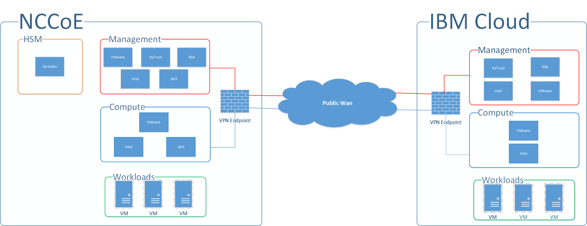
Figure 1-1 shows the high-level architecture. It depicts the four main components that comprise the build:
HSM component: This build utilizes HSMs to store sensitive keys within the environment.
Management component: Identical functional management components are instantiated within each cloud instance. At a minimum, each management component includes VMware running the virtualization stack, HyTrust providing the asset tagging policy enforcement aspect, and RSA providing network-visibility, dashboard, and reporting capabilities. The management components are connected through the VPN to represent one logical management element.
Compute component: The compute components host the tenant workload virtual machines (VMs). Asset tagging is provisioned on the compute servers so that policy can be assigned and enforced to ensure that tenant workloads reside on servers that meet specific regulatory compliance requirements.
Workload component: The workload components include VMs, data storage, and networks owned and operated by the tenant and data owner. Policies are applied to the workloads to ensure that they can run only on servers that meet specific requirements, such as asset tag policies.
Figure 1‑1: High-Level Solution Architecture
2 Dell EMC Product Installation and Configuration Guide
This section lists all prerequisites that must be met before the Dell EMC product installation and configuration can take place. This includes dependencies on any other parts of the example solution. It is recommended to download the latest security and hardening documentation from the Dell Technologies support site for the following products:
Dell PowerEdge R740xD
Dell EMC Unity
Dell Networking S3048/4048-ON Networking
Dell Avamar
Dell Data Domain
This section explains how to install and configure the Dell EMC products and hardening guides. It points to existing documentation whenever possible, so this document only includes supplemental information, such as configuration settings recommended for the example solution that differ from the defaults.
2.1 Dell EMC Unity Hardening Guidance
Dell EMC utilizes a derivative of SUSE Linux 12 for its embedded operating system (OS) to manage the hardware and provide storage device services. Dell EMC Unity has a simple command-line capability to enable security hardening that meets the guidelines of the SUSE Linux 12 Security Technical Implementation Guide (STIG). Some of the hardening steps to meet STIG requirements are turned on by running service scripts.
Dell EMC Unity Data at Rest Encryption (D@RE) protects against unauthorized access to lost, stolen, or failed drives by ensuring all sensitive user data on the system is encrypted as it is written to disk. It does this through hardware-based encryption modules located in the serial attached SCSI (SAS) controllers and 12 gigabits per second (Gb/s) SAS IO modules which encrypt data as it is written to the back-end drives, and decrypt data as it is retrieved from these drives.
To enable and configure D@RE, first read the Dell EMC Unity: Data at Rest Encryption paper and follow the instructions in these sections:
Enabling D@RE
Enabling External Key Management
Keystore Backup
Audit Log and Checksum Retrieval
Next, configure the storage system to enable Federal Information Processing Standards (FIPS) 140-2 mode for the Transport Layer Security (TLS) modules that encrypt client management traffic. Directions for doing so are in the “Management support for FIPS 140-2” section of Chapter 4 of the Dell EMC Unity Family Security Configuration Guide. Finally, to enable STIG mode on the Dell EMC Unity system (for physical deployments only), follow the three steps, in order, for hardening your storage system in the “Manage STIG mode” section of Chapter 8 in the same Security Configuration Guide.
2.2 Dell Networking S4048-ON, S3048-ON, OS9 Hardening
This section provides example configurations for release 9.14(1.0) on the S3048–ON and shows how to configure the Dell EMC Networking system in accordance with applicable DISA STIGs and DoD Unified Capabilities Requirements (UCR) 2013 Errata-1. For more information on configuring the S3048-ON, see the Dell EMC Configuration Guide for the S3048-ON System.
Configure the following features in the specified order. After you configure these features, configure the Functionality and Interoperability (Layer 2 Access) or Functionality and Interoperability (Layer 3 Access) features. For information about using the command line interface (CLI), see the Configuration Fundamentals and Getting Started sections in the Dell Networking Configuration Guide for your platform, or use the Dell Command Line Reference Guide for the S3048-ON System. To access all documentation for release 9.14, go to https://www.dell.com/support/home/en-us/product-support/product/dell-emc-os-9/docs.
Set the hostname:
hostname NCCOE-S4048-01Configure password policies:
Define the minimum security policy to create passwords. Ensure that the password attributes match your organization’s security policy.
password-attributes min-length 15 character-restriction lower 2
character-restriction upper 2 character-restriction numeric 2
character-restriction special 2
Set up the login lockout period to match your organization’s security policy:
password-attributes lockout-period 15Enable password with highest privileges:
enable password level 15 <clear-text password>
To enable FIPS cryptography mode, enter this command:
fips mode enableNote: Enable FIPS mode before you configure the features below. If you do not, the system will clear some of the configuration, and you must reconfigure some of the features.
Note: If the system fails to transition to FIPS mode, the system is not in a compliant state.
Enable SSH server:
ip ssh server cipher aes128-ctr aes192-ctr aes256-ctr
ip ssh server enable
ip ssh server mac hmac-sha1 hmac-sha2-256
Disable telnet server:
no ip telnet server enableDefine content addressable memory (CAM) allocation and optimization. CAM is a type of memory that stores information in the form of a lookup table. These CAM settings are required to configure a conformant IPv4 and IPv6 solution.
cam-acl 12acl 2 ipv4acl 2 ipv6acl 4 ipv4qos 2 12qoa 1 12pt 0 ipmacacl 0 vman-qos cfmacl 0 fedgoval
Enforce authentication and authorization of users connecting to system through the console or SSH, and then set the timer for terminating a session after 10 minutes of inactivity.
 login authentication ucraaa_console
 exec-timeout 10 0
 authorization exec ucraaa_console
line vty 0
 login authentication ucraaa_vty
 exec-timeout 10 0
 authorization exec ucraaa_vty
line vty 1
 login authentication ucraaa_vty
 exec-timeout 10 0
 authorization exec ucraaa_vty
line vty 2
 login authentication ucraaa_vty
 exec-timeout 10 0
 authorization exec ucraaa_vty
line vty 3
 login authentication ucraaa_vty
 exec-timeout 10 0
 authorization exec ucraaa_vty
line vty 4
 login authentication ucraaa_vty
 exec-timeout 10 0
 authorization exec ucraaa_vty
line vty 5
 login authentication ucraaa_vty
 exec-timeout 10 0
 authorization exec ucraaa_vty
line vty 6
 login authentication ucraaa_vty
 exec-timeout 10 0
 authorization exec ucraaa_vty
line vty 7
 login authentication ucraaa_vty
 exec-timeout 10 0
 authorization exec ucraaa_vty
line vty 8
 login authentication ucraaa_vty
 exec-timeout 10 0
 authorization exec ucraaa_vty
line vty 9
 login authentication ucraaa_vty
 exec-timeout 10 0
 authorization exec ucraaa_vty
Define a role-based user supplying an encrypted password:
username admin password 7 888dc89d1f1bca2882895c1658f993e7 privilege 15Limit open Transmission Control Protocol (TCP) connections by defining the wait duration for TCP connections as nine seconds:
ip tcp reduced-syn-ack-waitDefine the IPv4 static route:
ip route 0.0.0.0/0 192.168.101.1Configure IPv4 Open Shortest Path First (OSPF) routes:
router ospf 101
 router-id 192.168.101.3
 network 192.168.101.0/24 area 101
 area 101 nssa default-information-originate
 redistribute bgp 65001
Configure Media Access Control (MAC) settings:
mac-address-table station-move refresh-arp
mac-address-table agint-time 1000000
Configure system and audit log settings, such as syslog version, buffer size, logging server, and coredump destination:
service timestamps log datetime localtime msec show-timezone
service timestamps debug datetime localtime msec show-timezone
!
logging coredump stack-unit 1
logging coredump stack-unit 2
logging coredump stack-unit 3
logging coredump stack-unit 4
logging coredump stack-unit 5
logging coredump stack-unit 6
!
Set up the Network Time Protocol (NTP):
ntp server 192.168.4.10
ntp server 192.168.4.11
Configure the login banner text:
banner login ^CYou are accessing a U.S. Government (USG) Information
System (IS) that is provided for USG-authorized use only.
By using this IS (which includes any device attached to this IS), you consent
to the following conditions:
-The USG routinely intercepts and monitors communications on this IS for
purposes including, but not limited to, penetration testing, COMSEC monitoring,
network operations and defense, personnel misconduct (PM), law enforcement
(LE), and counterintelligence (CI) investigations.
-At any time, the USG may inspect and seize data stored on this IS.
-Communications using, or data stored on, this IS are not private, aresubject
to routine monitoring, interception, and search, and may be disclosed orused
for any USG-authorized purpose.
-This IS includes security measures (e.g., authentication and access controls)
to protect USG interests--not for your personal benefit or privacy.
-Not withstanding the above, using this IS does not constitute consent to PM,
LE or CI investigative searching or monitoring of the content of privileged
communications, or work product, related to personal representation or services
by attorneys, psychotherapists, or clergy, and their assistants. Such
communications and work product are private and confidential.^C
Configure the switch to securely bring the software image to its flash drive. Define where to upgrade the software image to (flash drive) and where to boot the software image from.
boot system stack-unit 1 primary system://B
boot system stack-unit 1 secondary system://B
boot system stack-unit 1 default system://A
!
Disable Support Assist:
eula-consent support-assist rejectConfigure redundancy:
redundancy auto-synchronize fullConfigure the loopback interface for management traffic:
interface Loopback 0
description NCCOE-S4048-02
ip address 10.0.2.2/32
no shutdown
!
Enter the File Transfer Protocol (FTP) source interface, for example Loopback 1:
ip ftp source-interface loopback 1Enter the clock timezone for your system:
clock timezone Eastern -5
clock summer-time Eastern recurring 2 Sun Mar 02:00 1 Sun Nov 02:00
!
To disable IP source routing, enter the following command:
no ip source-routeConfigure reload behavior:
reload-type
boot-type normal-reload
config-scr-download enable
vendor-class-identifier “ “
!
Enable login statistics:
login concurrent-session limit 3
login statistics enable
!
Configure the management interface:
interface ManagementEthernet 1/1
description OOB_MGMT
ip address 10.10.10.11/24
no shutdown
!
2.2.1 Functionality and interoperability (layer 3 access)
This section describes how to configure functionality and interoperability using Layer 2. The example configurations shown in the following sections are based on the requirements in UCR 2013 Errata 1. Your site needs to update the configurations as the UCR requirements periodically change.
Configure the Link Layer Discovery Protocol (LLDP):
protocol lldp
 advertise dot1-tlv port-vlan-id
 advertise dot3-tlv max-frame-size
 advertise management-tlv management-address system-capabilities
system-description system-name
 advertise interface-port-desc
!
The following configurations create aggregated links and were applied to interfaces to enable link aggregation control protocol (LACP). The aggregated links were then subscribed to virtual local area networks (VLANs). For complete information about this feature, see the Port Channel Interfaces and Link Aggregation Control Protocol (LACP) sections in the Dell Networking Configuration Guide and the Dell Networking Command Line Reference Guide.
 interface Port-channel 64
 description LAG to IB-MGMT switches
 no ip address
 switchport
 vlt-peer-lag port-channel 64
 no shutdown
!
interface Port-channel 67
 no ip address
 mtu 9216
 portmode hybrid
 switchport
 spanning-tree rstp edge-port bpduguard shutdown-on-violation
 spanning-tree 0 portfast bpduguard shutdown-on-violation
 lacp fast-switchover
 vlt-peer-lag port-channel 67
 no shutdown
!
interface Port-channel 68
 no ip address
 mtu 9216
 portmode hybrid
 switchport
 spanning-tree rstp edge-port bpduguard shutdown-on-violation
 spanning-tree 0 portfast bpduguard shutdown-on-violation
 lacp fast-switchover
 vlt-peer-lag port-channel 68
 no shutdown
!
interface Port-channel 127
 description VLTi
 no ip address
 channel-member fortyGigE 1/51,1/52
 no shutdown
!
Apply input and output policies to physical interfaces. The following are the configurations in the NCCoE lab and can be run on the switch CLI as written to duplicate:
interface TenGigabitEthernet 1/1
 description mgt-nccoe-esxi-01
 no ip address
 mtu 9216
 switchport
 spanning-tree rstp edge-port bpduguard shutdown-on-violation
 spanning-tree 0 portfast bpduguard shutdown-on-violation
 no shutdown
!
interface TenGigabitEthernet 1/2
 description mgt-nccoe-esxi-02
 no ip address
 mtu 9216
 switchport
 spanning-tree rstp edge-port bpduguard shutdown-on-violation
 spanning-tree 0 portfast bpduguard shutdown-on-violation
 no shutdown
!
interface TenGigabitEthernet 1/3
 description mgt-nccoe-esxi-03
 no ip address
_ mtu 9216
 switchport
 spanning-tree rstp edge-port bpduguard shutdown-on-violation
 spanning-tree 0 portfast bpduguard shutdown-on-violation
 no shutdown
!
interface TenGigabitEthernet 1/4
 description mgt-nccoe-esxi-04
 no ip address
 mtu 9216
 switchport
 spanning-tree rstp edge-port bpduguard shutdown-on-violation
 spanning-tree 0 portfast bpduguard shutdown-on-violation
 no shutdown
!
interface TenGigabitEthernet 1/5
 description mgt-nccoe-esxi-01
 no ip address
 mtu 9216
 switchport
 spanning-tree rstp edge-port bpduguard shutdown-on-violation
 spanning-tree 0 portfast bpduguard shutdown-on-violation
 no shutdown
!
interface TenGigabitEthernet 1/6
 description mgt-nccoe-esxi-02
 no ip address
 mtu 9216
 switchport
 spanning-tree rstp edge-port bpduguard shutdown-on-violation
 spanning-tree 0 portfast bpduguard shutdown-on-violation
 no shutdown
!
interface TenGigabitEthernet 1/7
 description mgt-nccoe-esxi-03
 no ip address
 mtu 9216
 switchport
 spanning-tree rstp edge-port bpduguard shutdown-on-violation
 spanning-tree 0 portfast bpduguard shutdown-on-violation
 no shutdown
!
interface TenGigabitEthernet 1/8
 description mgt-nccoe-esxi-04
 no ip address
 mtu 9216
 switchport
 spanning-tree rstp edge-port bpduguard shutdown-on-violation
 spanning-tree 0 portfast bpduguard shutdown-on-violation
 no shutdown
!
interface TenGigabitEthernet 1/9
 description comp-nccoe-esxi-01
 no ip address
 mtu 9216
 switchport
 spanning-tree rstp edge-port bpduguard shutdown-on-violation
 spanning-tree 0 portfast bpduguard shutdown-on-violation
 no shutdown
!
interface TenGigabitEthernet 1/10
 description comp-nccoe-esxi-02
 no ip address
 mtu 9216
 switchport
 spanning-tree rstp edge-port bpduguard shutdown-on-violation
 spanning-tree 0 portfast bpduguard shutdown-on-violation
 no shutdown
!
interface TenGigabitEthernet 1/11
 description comp-nccoe-esxi-03
 no ip address
 mtu 9216
 switchport
 spanning-tree rstp edge-port bpduguard shutdown-on-violation
 spanning-tree 0 portfast bpduguard shutdown-on-violation
 no shutdown
!
interface TenGigabitEthernet 1/12
 description comp-nccoe-esxi-04
 no ip address
 mtu 9216
 switchport
 spanning-tree rstp edge-port bpduguard shutdown-on-violation
 spanning-tree 0 portfast bpduguard shutdown-on-violation
 no shutdown
!
interface TenGigabitEthernet 1/13
 description comp-nccoe-esxi-01
 no ip address
 mtu 9216
 switchport
 spanning-tree rstp edge-port bpduguard shutdown-on-violation
 spanning-tree 0 portfast bpduguard shutdown-on-violation
 no shutdown
!
interface TenGigabitEthernet 1/14
 description comp-nccoe-esxi-02
 no ip address
 mtu 9216
 switchport
 spanning-tree rstp edge-port bpduguard shutdown-on-violation
 spanning-tree 0 portfast bpduguard shutdown-on-violation
 no shutdown
!
interface TenGigabitEthernet 1/15
 description comp-nccoe-esxi-03
 no ip address
 mtu 9216
 switchport
 spanning-tree rstp edge-port bpduguard shutdown-on-violation
 spanning-tree 0 portfast bpduguard shutdown-on-violation
 no shutdown
!
interface TenGigabitEthernet 1/16
 description comp-nccoe-esxi-04
 no ip address
 mtu 9216
 switchport
 spanning-tree rstp edge-port bpduguard shutdown-on-violation
 spanning-tree 0 portfast bpduguard shutdown-on-violation
 no shutdown
!
interface TenGigabitEthernet 1/31
 description TO-UNITY-ARRAY
 no ip address
 mtu 9216
!
port-channel-protocol LACP
 port-channel 68 mode active
no shutdown
!
interface TenGigabitEthernet 1/32
 description TO-UNITY-ARRAY
 no ip address
 mtu 9216
!
port-channel-protocol LACP
 port-channel 67 mode active
no shutdown
!
interface TenGigabitEthernet 1/47
 description NorthBound Firewal X5
 no ip address
 switchport
 no shutdown
!
interface TenGigabitEthernet 1/48
 description IB-MGMT Switch Stack Port 49
 no ip address
!
port-channel-protocol LACP
 port-channel 64 mode active
 no shutdown
interface fortyGigE 1/51
 description VLTi
 no ip address
 no shutdown
!
interface fortyGigE 1/52
 description VLTi
 no ip address
 no shutdown
!
interface fortyGigE 1/53
 description to Spine Switch 4 Port 54
 ip address 192.168.1.1/31
 no shutdown
!
interface fortyGigE 1/54
 description to Spine Switch 3 Port 54
 ip address 192.168.2.1/31
 no shutdown
!
interface Port-channel 64
 description LAG to IB-MGMT Switches
 no ip address
 switchport
 vlt-peer-lag port-channel 64
 no shutdown
!
interface Port-channel 67
 no ip address
 mtu 9216
 portmode hybrid
 switchport
 spanning-tree rstp edge-port bpduguard shutdown-on-violation
 spanning-tree 0 portfast bpduguard shutdown-on-violation
 lacp fast-switchover
 vlt-peer-lag port-channel 67
 no shutdown
!
interface Port-channel 68
 no ip address
 mtu 9216
 portmode hybrid
 switchport
 spanning-tree rstp edge-port bpduguard shutdown-on-violation
 spanning-tree 0 portfast bpduguard shutdown-on-violation
 lacp fast-switchover
 vlt-peer-lag port-channel 68
 no shutdown
!
interface Port-channel 127
 description VLTi
 no ip address
 channel-member fortyGigE 1/51,1/52
 no shutdown
!
interface Port-channel 128
 no ip address
 shutdown
!

Honor 802.1p markings on incoming traffic and assign them to a default
queue service-class dynamic dot1p

Include overhead fields in rate-metering calculations
qos-rate-adjust 20
2.2.2 VLANs
Define the network-specific VLAN interfaces. For complete information about this feature, see the Virtual LANs (VLANs) section in the Dell Networking Configuration Guide and the Dell Networking Command Line Reference Guide. The following are the configurations in the NCCoE lab and can be run on the switch CLI as written to duplicate:
interface Vlan 1
!untagged Port-channel 67-68,127
!
interface Vlan 101
 ip address 192.168.101.3/24
 untagged TenGigabitEthernet 1/47
!
 vrrp-group 101
  virtual-address 192.168.101.2
 no shutdown
!
interface Vlan 103
 no ip address
 shutdown
!
interface Vlan 104
 description nccoe-m01-vds01-managemnt
 ip address 192.168.4.252/24
 tagged TenGigabitEthernet 1/1-1/16,1/21
 tagged Port-channel 64,127
!
 vrrp-group 104
  priority 254
  virtual-address 192.168.4.254
 no shutdown
!
interface Vlan 110
 description nccoe-m01-vds01-nfs
 ip address 192.168.10.252/24
 tagged TenGigabitEthernet 1/1-1/16,1/21
 tagged Port-channel 67-68,127
!
 vrrp-group 110
  priority 254
  virtual-address 192.168.10.254
 no shutdown
!
interface Vlan 120
 description nccoe-m01-vds01-vmotion
 ip address 192.168.20.252/24
 tagged TenGigabitEthernet 1/1-1/8
 tagged Port-channel 127
!
 vrrp-group 120
  priority 254
  virtual-address 192.168.20.254
 no shutdown
!
interface Vlan 130
 description nccoe-m01-vds01-vsan
 ip address 192.168.30.252/24
 tagged TenGigabitEthernet 1/1-1/8
 tagged Port-channel 127
!
 vrrp-group 130
  priority 254
  virtual-address 192.168.30.254
 no shutdown
!
interface Vlan 140
 description nccoe-m01-vds01-replication
 ip address 192.168.40.252/24
 tagged TenGigabitEthernet 1/1-1/8
 tagged Port-channel 127
!
 vrrp-group 140
  priority 254
  virtual-address 192.168.40.254
 no shutdown
!
interface Vlan 150
 description VTEP VLAN
 ip address 192.168.50.252/24
 tagged TenGigabitEthernet 1/1-1/16
 tagged Port-channel 127
!
 vrrp-group 150
  priority 254
  virtual-address 192.168.50.254
 no shutdown
!
interface Vlan 160
 description nccoe-m01-vds01-uplink01
 ip address 192.168.60.252/24
 tagged TenGigabitEthernet 1/1-1/16
!
 vrrp-group 160
  priority 254
  virtual-address 192.168.60.254
 no shutdown
!
interface Vlan 180
 description nccoe-m01-vds01-ext-management
 no ip address
 tagged TenGigabitEthernet 1/1-1/16
 tagged Port-channel 127
 no shutdown
!
interface Vlan 210
 description nccoe-w01-vds01-nfs
 ip address 192.168.210.252/24
 tagged TenGigabitEthernet 1/1-1/16
 tagged Port-channel 127
!
 vrrp-group 210
  priority 254
  virtual-address 192.168.210.254
 no shutdown
!
interface Vlan 220
 description nccoe-w01-vds01-vmotion
 ip address 192.168.220.252/24
 tagged TenGigabitEthernet 1/9-1/16
 tagged Port-channel 127
!
 vrrp-group 220
  priority 254
  virtual-address 192.168.220.254
 no shutdown
!
interface Vlan 230
 description nccoe-w01-vds01-vsan
 ip address 192.168.230.252/24
 tagged TenGigabitEthernet 1/9-1/16
 tagged Port-channel 127
!
 vrrp-group 230
  priority 254
  virtual-address 192.168.230.254
 no shutdown
!
interface Vlan 240
 description VTEP VLAN
 ip address 192.168.240.252/24
 tagged TenGigabitEthernet 1/1-1/16
 tagged Port-channel 127
!
 vrrp-group 240
  priority 254
  virtual-address 192.168.240.254
 no shutdown
!
interface Vlan 1000
 description collapsed leaf edge bgp peering network
 ip address 192.168.100.1/24
 no shutdown
!
interface Vlan 1110
 description nccoe-w01-vds01-uplink01
 ip address 192.168.110.252/24
 tagged TenGigabitEthernet 1/1-1/16
!
 vrrp-group 111
  priority 254
  virtual-address 192.168.110.254
 no shutdown
!
2.3 Dell PowerEdge Hardening
Unified Extensible Firmware Interface (UEFI) Secure Boot is a technology that secures the boot process by verifying if the drivers and OS loaders are signed by the key that is authorized by the firmware. When enabled, Secure Boot makes sure that:
the BIOS boot option is disabled;
only UEFI-based OSs are supported for OS deployment in all management applications; and
only authenticated EFI images and OS loaders are started from UEFI firmware.
You can enable or disable the Secure Boot attribute locally or remotely using Dell EMC management applications. Lifecycle Controller supports deploying an OS with the Secure Boot option only in the UEFI boot mode.
There are two BIOS attributes that are associated with Secure Boot:
Secure Boot — Displays if the Secure Boot is enabled or disabled.
Secure Boot Policy — Allows you to specify the policy or digital signature that the BIOS uses to authenticate. The policy can be classified as:
Standard — The BIOS uses the default set of certificates to validate the drivers and OS loaders during the boot process.
Custom — The BIOS uses the specific set of certificates that you import or delete from the standard certificates to validate the drivers and OS loaders during the boot process.
Note: The secure boot policy settings made in the BIOS can also be changed on the Lifecycle Controller graphical user interface (GUI).
2.4 Avamar Security Hardening
Avamar servers running the SUSE Linux Enterprise Server (SLES) OS can implement various server security hardening features. These features are primarily targeted at customers needing to comply with DoD STIGs for Unix requirements. The following are specific steps to harden different components and services on the Avamar server. All come from Chapter 7 of the Dell EMC Avamar Product Security Guide.
Disabling Samba (under “Level-1 security hardening”)
Preventing unauthorized access to GRUB configuration (under “Level-1 security hardening”)
Preventing the OS from loading USB storage (under “Level-1 security hardening”)
Updating OpenSSH (under “Level-3 security hardening”)
Disabling RPC (under “Level-3 security hardening”)
Configuring the firewall to block access to port 9443 (under “Level-3 security hardening”)
Changing file permissions (under “Level-3 security hardening”)
3 Gemalto Product Installation and Configuration Guide
This section describes the steps and commands to configure the Gemalto Luna 6 HSM and create partitions on it for networked servers to use.
3.1 Gemalto Luna 6 Initialization
The following commands are for initializing the system and configuring the Luna HSM networking. When the system is logged into for the first time, the default user is admin and the password is PASSWORD. A prompt is immediately presented upon successful login to change the default password. Once the password is changed, run the following commands for configuration purposes:
Set the time zone to US Eastern:
sysconf timezone set US/EasternSet the date/time format:
syscont time HH:MM YYYMMDDSet the hostname:
net hostname TCHSMSet the Domain Name System (DNS) server:
net dns add nameserver 172.16.1.11Set the network interface card (NIC) configuration for eth0 on the HSM:
net interface -device eth0 -ip 172.16.1.22 -netmask 255.255.255.0
-gateway 172.16.1.254
Perform the following steps to generate and use a new HSM server certificate:
Generate the certificate:
sysconf regenCertBind the cert to eth0:
ntls bind eth0Verify the status of Network Trust Links (NTLS):
ntls show
The following commands initialize the HSM and set up policies for logging in and which algorithms it can use:
Initialize the HSM and set the login timeout:
hsm PED timeout set -type -seconds 300Next, log in as Security Officer:
hsm init -label NCCoE_LabPolicy 12 controls non-FIPS compliant algorithms. Setting the value to zero disables any non-FIPS compliant algorithms:
hsm changePolicy -policy 12 -v 0
3.2 Create HSM Partition
The following steps create the individual partition in the HSM that will be used for the HyTrust KeyControl cluster to use as its key management system (KMS):
hsm loginCreate the HSM partition to be used for KeyControl:
partition create -partition HyTrust_KeyControlSet the password for the newly created partition:
partition changePW -partition HyTrust_KeyControl -newpw <new
password> -oldpw <old password>
Allow activation:
partition changePolicy -partition HyTrust_KeyControl -policy 22 -v 1Allow auto-activation:
partition changePolicy -partition HyTrust_KeyControl -policy 23 -v 1Activate the newly created partition:
partition activate -partition HyTrust_KeyControlShow partition serial number for high availability:
partition show
4 HyTrust Product Installation and Configuration Guide
This build implemented the HyTrust KeyControl, DataControl, CloudControl, and CloudAdvisor appliances. The following subsections show how the installation and configurations were performed, as well as how they were integrated with other components in the build.
4.1 HyTrust KeyControl Setup
First, follow the directions on these pages:
Installing KeyControl from an OVA Template (note: OVA stands for open virtual appliance)
Adding a New KeyControl Node to an Existing Cluster (OVA Install)
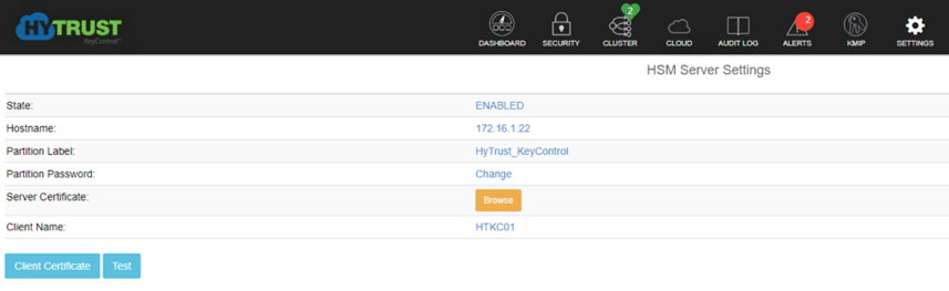
Next, in order to use the Gemalto Luna HSM as the KMS server to protect its keys, there must be connectivity between KeyControl and the HSM. To configure the HSM in KeyControls:
Log in to the web user interface (UI) and click the SETTINGS button.
Once in the Settings menu, click on the “HSM Server Settings” link to configure the HSM.
Enter in the following information for the Gemalto Luna HSM:
hostname or IP address
partition label that was created in the Gemalto steps
partition password
server certificate file
client name for this KeyControl server
When the information is entered correctly and the KeyControl server can communicate with and authenticate to the Gemalto HSM, the state will show as “ENABLED”.
4.2 HyTrust DataControl Setup
Follow the directions on these pages:
4.3 HyTrust CloudControl Appliance Setup
Follow the directions on these pages:
Configuring High Availability
Adding Hosts to CloudControl
Verify and Update Host Trust (and Host Icons Used in CloudControl)
For more information on PolicyTags provisioning and evaluation, see the “PolicyTags Provisioning” section in chapter 6 of the Administration Guide for HyTrust CloudControl.
4.3.1 Provisioning PolicyTags
To provision the PolicyTags, you need to perform the following tasks:
Collect the UUID (Universally Unique Identifier) information for each Trusted host.
Generate and run the esxcli commands for hardware provisioning for each Trusted host.
Verify that the PolicyTags are provisioned.
4.3.1.1 Collect UUIDs of Good Known Hosts (GKHs) and Trusted Hosts
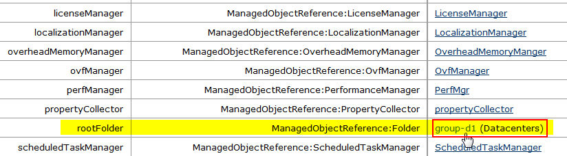
The UUID information for the GKHs and Trusted hosts can be collected from the vCenter Managed Object Browser (MOB). You will need to obtain the UUID for each GKH and Trusted host.
Log into the vCenter Managed Object Browser at
https://<VSPHERE_URL>/mob.Perform the following series of page selections to reach the host page for each of your Intel TXT-enabled hosts:
Managed Object ID (page)
NAME (selection row)
VALUE (link to select)
ServiceInstance
Content
content
content
rootFolder
group-d#
group-d#
childEntity
datacenter-#
datacenter-#
hostFolder
group-h#
group-h#
childEntity
domain-c#
domain-c#
host
host-## (Intel TXT host)
On the Hosts page, click Summary.
On the Summary page, click Hardware. The Hardware page contains the UUID information.
Repeat this for each Trusted host.
4.3.1.2 Generate esxcli Commands
Use the CloudControl cli to generate esxcli commands that can be used for hardware provisioning.
Log into CloudControl as the ascadminuser, and run the following command:
asc tas --export-certsThis generates a file in /tmp in the following format: export–xxxx-xx-xxx.tgz
Navigate to the /tmp folder and extract the file using the following command:
tar -xvf export--xxxx-xx-xxx.tgzThe extraction process lists several files, including the sha1.bin for each Trusted ESXi host.
Example:
export--2018-08-27T23-44-43Z/6aa6af76/14f6/42e8/b452/6aa6af76-14f6-42e8-b452-dc27fe259e1a/system--6aa6af76-14f6-42e8-b452-dc27fe259e1a.der

export--2018-08-27T23-44-43Z/6aa6af76/14f6/42e8/b452/6aa6af76-14f6-42e8-b452-dc27fe259e1a/system--6aa6af76-14f6-42e8-b452-dc27fe259e1a.sha1.bin

export--2018-08-27T23-44-43Z/6aa6af76/14f6/42e8/b452/6aa6af76-14f6-42e8-b452-dc27fe259e1a/system--6aa6af76-14f6-42e8-b452-dc27fe259e1a.sha256.bin

export--2018-08-27T23-44-43Z/6aa6af76/14f6/42e8/b452/6aa6af76-14f6-42e8-b452-dc27fe259e1a/system--6aa6af76-14f6-42e8-b452-dc27fe259e1a.metadata.txt

export--2018-08-27T23-44-43Z/dddfda66/314e/4378/8f4d/dddfda66-314e-4378-8f4d-060b5d885038/system--dddfda66-314e-4378-8f4d-060b5d885038.der

export--2018-08-27T23-44-43Z/dddfda66/314e/4378/8f4d/dddfda66-314e-4378-8f4d-060b5d885038/system--dddfda66-314e-4378-8f4d-060b5d885038.sha1.bin

export--2018-08-27T23-44-43Z/dddfda66/314e/4378/8f4d/dddfda66-314e-4378-8f4d-060b5d885038/system--dddfda66-314e-4378-8f4d-060b5d885038.sha256.bin

export--2018-08-27T23-44-43Z/dddfda66/314e/4378/8f4d/dddfda66-314e-4378-8f4d-060b5d885038/system--dddfda66-314e-4378-8f4d-060b5d885038.metadata.txt
Navigate to the extracted directory, for example:
cd /tmp/export--xxxx-xx-xxxAt the prompt, type the following command:
grep -E -- '"(id|subject)" : ' json.dump | grep -A1 '<Trusted-Host-UUID>'This command returns the “subject” and the “id.” Example:
"subject" : "4c4c4544-0032-3010-8035-b5c04f333832",
"id" : "6aa6af76-14f6-42e8-b452-dc27fe259e1a"
Run the following
hexdumpcommand for each Trusted host, where <sha1.bin file path> matches the “id” for the specific host:hexdump -e '"esxcli hardware tpm tag set --data=" 20/1 "%1.2x" ";\n"' <sha1.bin file path>
This returns the
esxclicommand.Example:
hexdump -e '"esxcli hardware tpm tag set --data=" 20/1 "%1.2x" ";\n"'
6aa6af76/14f6/42e8/b452/6aa6af76-14f6-42e8-b452-dc27fe259e1a/system--6aa6af76-14f6-42e8-b452-dc27fe259e1a.sha1.bin

**esxcli hardware tpm tag set --data=46f048ce41afdfa686e4c00f9fd67a2b71d1c749;**
4.3.1.3 Run esxcli Commands
Run the esxcli commands for each Trusted host to provision the hardware
tags.
Put the Trusted host into maintenance mode.
Log in to the ESXi host as
root.Run the specific
esxclicommand for the Trusted host. The command is part of thehexdumpoutput.Example:
esxcli hardware tpm tag set --data=46f048ce41afdfa686e4c00f9fd67a2b71d1c749;Restart the ESXi host. The host should still be in maintenance mode.
4.3.2 Policy Interaction
See the Policy Interaction webpage for more information on how policy enforcement works.
4.4 HyTrust CloudAdvisor Appliance Setup
Follow the directions on these pages:
5 IBM Product Installation and Configuration Guide
This section covers all the aspects of installing and configuring the IBM products used to build the example solution. Note that the information in this section reflects product and service names, features, options, and configurations as of when the build was performed. The IBM products in this section are cloud-based with web-based documentation, and they do not use versioning conventions, so it is not possible to reference the documentation that was used during this build. As of this writing, the latest information from IBM is available through the IBM Cloud for VMware Solutions site at https://www.ibm.com/cloud/vmware.
5.1 ICSV Deployment
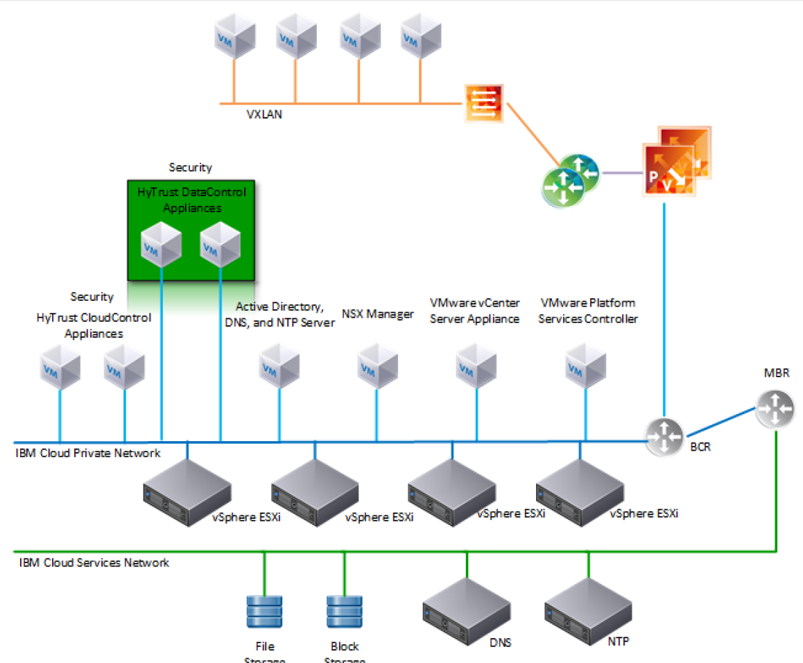
IBM Cloud Secure Virtualization (ICSV) combines the power of IBM Cloud, VMware Cloud Foundation, HyTrust security software, and Intel TXT-enabled hardware to protect virtualized workloads. ICSV is deployed on the IBM Cloud infrastructure according to a VMware, HyTrust, IBM, and Intel-validated design reference architecture. IBM Cloud Secure Virtualization is initially deployed as a four-node cluster within the choice of clients of available IBM Cloud Data Centers worldwide. Figure 5-1 displays a reference architecture for ICSV that shows the separation between IBM Cloud services, ICSV provisioned infrastructure, and tenant VMs. ICSV utilizes the IBM Cloud Services Network to enable provisioning the IBM Cloud Private Network to a customer, which in turn protects the virtualized workloads.
Figure 5‑1: Reference Architecture for ICSV
To deploy the ICSV reference architecture stack, IBM has streamlined the process in three phases for the customer.
5.1.1 Pre-deployment
This phase starts after the customer has agreed to purchase the ICSV stack in the IBM cloud and has identified the use cases using a workshop or IBM Garage methodology. For the NCCoE project, we had a good understanding of the use case and the capabilities provided by ICSV. To achieve success in all three phases, the IBM Services team filled out Table 5-1 and Table 5-2. The information provided in each table helped us with decisions in later steps.
Table 5‑1: Example of IBM Cloud Contact Information Template
Name |
Email Address |
Phone Number |
|
|---|---|---|---|
Client Sponsor |
|||
Client Technical Lead |
|||
Client Oversight |
|||
Client Sales Engineer |
|||
IBM Account Exec |
|||
IBM Sales Contact |
|||
IBM OM Contact |
|||
IBM Program Manager (PM) |
|||
IBM Consultant |
|||
Other IBMers |
|||
Vendors info (if applicable) |
Table 5‑2: ICSV Requirement & Deployment Template
Client Input Variables |
Choices |
Example Values |
|---|---|---|
SoftLayer user id |
<user_name> from IAAS |
|
SoftLayer API key |
<user_key> from IAAS |
|
Deployment - VMware Cloud Foundation (VCF) or vCenter Server (VCS) |
VCF or VCS |
VCS |
VCS deployment details |
||
Instance name |
- |
TrustedCld |
# of hosts (min. 3) |
3 to 20 |
4 |
Instance |
Primary or Secondary |
Primary |
Host configuration |
Small, Medium, Large, Custom |
Custom |
Cores |
16, 24, 28, 36 |
24 |
Intel core base |
2.1, 2.2, 2.3 GHz |
2.2 GHz |
RAM |
64 GB-1.5 TB |
256 GB |
Data center location |
Dallas, DC, Boulder, etc. |
Dallas |
Data storage |
NFS or VSAN |
VSAN |
Size of each data storage |
1, 2, 4, 8, 12 TB |
2 TB |
Performance of file shares |
2, 4, 10 IOPS/GB |
NA |
NFS version - v3.0 or v4.1 for shared drives |
NA |
|
Windows AD |
VSI OR VM |
VM |
Host prefix |
- |
Esxi0 |
Domain name (used in Windows AD) |
- |
nccoe.lab |
Sub domain (used by VM) |
- |
icsv |
VM License |
BYO or Purchase |
Purchase |
VM Vcenter Server License |
- |
Standard |
VM vSphere License |
- |
Enterprise Plus |
VM NSX License |
- |
Enterprise |
Services to be added |
||
Veeam |
Yes / No |
No |
F5 |
Yes / No |
No |
Fortinet Security Appliance |
Yes / No |
No |
Fortinet Virtual Appliance |
Yes / No |
No |
Zerto version 5.0 |
Yes / No |
No |
HyTrust DataControl |
Yes / No |
Yes |
HyTrust CloudControl |
Yes / No |
Yes |
IBM Spectrum Protect Plus |
Yes / No |
No |
5.1.2 Automation deployment
The following are steps for ordering an ICSV instance through the IBM portal.
Log into the IBM Cloud infrastructure customer portal at https://cloud.ibm.com/login.
From the top left corner, select the “Hamburger” menu, then select VMware from the drop-down menu on the left side.
Click on Settings and make sure the correct application programming interface (API) key is entered before provisioning the solution.
On the IBM Cloud for VMware Solutions screen, select VMware vCenter Server on IBM Cloud.
On the next screen, select vCenter Server and click the Create button.
In the next window, type in the Instance Name and make sure Primary Instance is highlighted for Instance type. For the Licensing options, select Include with purchase for all of them. For the NSX License, select Enterprise from the drop-down menu.
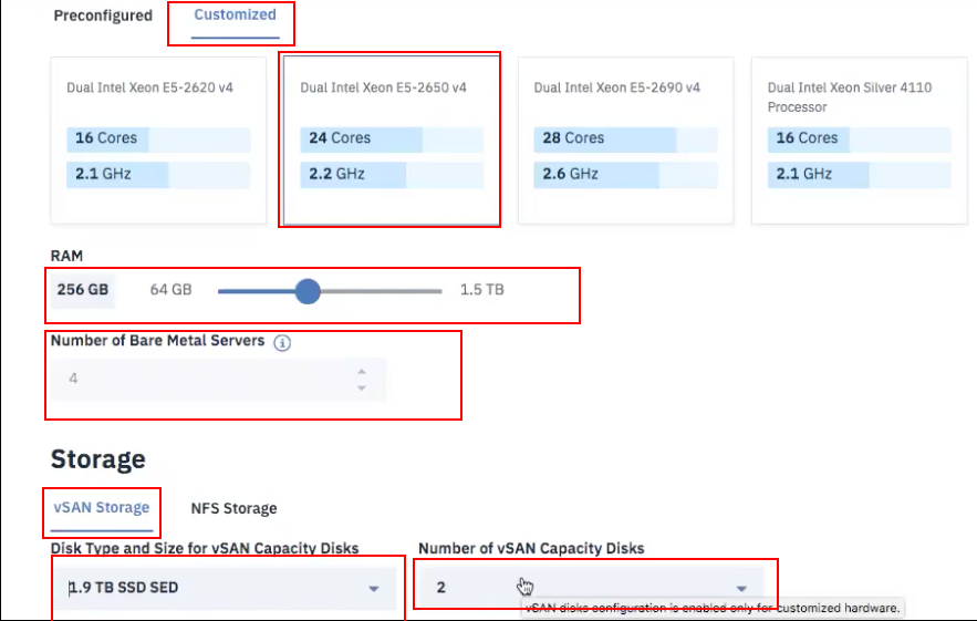
Under Bare Metal Server:
For the Data Center Location, open the drop-down menu for NA South and select DAL09.
Select Customized since our workload needs a virtual storage area network (VSAN), which requires a minimum of a four-node cluster.
Under Storage:
Select vSan Storage.
Set the Disk Type and Size for vSAN Capacity Disks to 1.9 TB SSD SED.
Select 2 from the drop-down menu for the Number of vSAN Capacity Disks.
For vSAN License, select Include with purchase and then choose Enterprise from the drop-down menu.
For the Network Interface, enter the following:
Hostname Prefix:
esxiSubdomain Label:
icsvDomain Name:
nccoe.lab
Select Order New VLANs.
Under DNS Configuration, select Two highly available dedicated Windows Server VMs on the management cluster.
Under Services, remove Veeam on IBM Cloud 9.5 and select HyTrust CloudControl on IBM Cloud 5.3 and HyTrust DataControl on IBM Cloud 4.1.
Click on the Provision button in the bottom right-hand corner. This will begin the provisioning process for the selected topology. It can take roughly 24 hours to complete the automation deployment. Once deployment has completed, you should receive an email notification.
5.1.3 Post-deployment
This information is needed to set up HyTrust CloudControl (HTCC) to interact with Windows AD and vCenter. The IBM Service team will set up HTCC so it is ready for HyTrust configuration based on the use cases required by the client. Table 5-3 shows examples of HTCC configuration parameters.
Table 5‑3: Examples of HTCC Configuration Parameters
Client Input Variables |
Choices |
Example Values |
|---|---|---|
SMTP Server - for email notifications |
Point to company or enable third party sendgrid |
sendgrid |
SNMP Server |
||
NTP Server (provided by SL) |
Use default (10.0.77.54), unless specified |
10.0.77.54 (time.service.ne tworklayer.com) |
Windows AD Groups and Users |
||
Group / Users |
||
HTCC Super Admin group |
ht_superadmin_users |
ht_superadmin_users |
User in: ht_superadmin_users (Full Admin) |
Administrator |
Administrator |
User: ht_ldap_svc HTCC to AD login user |
ht_ldap_svc unless specified by client |
ht_ldap_svc |
User: ht_vcenter_svc HTCC to vCenter login user |
ht_vcenter_svc unless specified by client |
ht_vcenter_svc |
H/W Policy tags |
||
Country (from BMXI portal, as displayed) |
Country name |
USA |
State/Province |
State or province name |
DAL |
Physical Data Center (PDC) |
Location (IBM Cloud Data Center name as displayed) |
DAL09 |
Region |
Region where data center is located |
South West |
Classification (User ID-Client name) |
Custom |
The IBM services team gathers information from the client, such as the examples in Table 5-4, after understanding the use cases. The information will be used to configure HyTrust, VMware, and Intel TPM/TXT to enforce workload rules and policy. Once post-deployment is completed, the IBM services team will perform a verification test and deliver the asset to the client.
Table 5‑4: Examples of Additional HTCC Configuration Parameters
Client Input Variables
Choices
Example Values
SMTP Server - for email notifications
Point to company or enable third party sendgrid
sendgrid
SNMP Server
?
?
HyTrust H/W TPM Policy Tags
HTCC Compliance Templates - Custom
Name
Based on PCI, NIST, …
HTCC Scheduled Events
Name
Template or Label
HTCC Policy Labels
Name
Template
HTCC Roles
Default Roles
Users
ASC_ARCAdmin
default
ASC_ARCAdmin
ASC_ARCAssessor
default
ASC_ARCAssessor
ASC_ApplAdmin
default
ASC_ApplAdmin
ASC_BackupAdmin
default
ASC_BackupAdmin
ASC_BasicLogin
default
ASC_BasicLogin
ASC_CoreApplAdmin
default
ASC_CoreApplAdmin
ASC_DCAdmin
default
ASC_DCAdmin
ASC_ESXMAdmin
default
ASC_ESXMAdmin
ASC_NetworkAdmin
default
ASC_NetworkAdmin
ASC_PolicyAdmin
default
ASC_PolicyAdmin
ASC_RoleAdmin
default
ASC_RoleAdmin
ASC_StorageAdmin
default
ASC_StorageAdmin
ASC_SuperAdmin
default
ASC_SuperAdmin
ASC_ThirdParty
default
ASC_ThirdParty
ASC_UCSLogin
default
ASC_UCSLogin
ASC_VIAdmin
default
ASC_VIAdmin
ASC_VMPowerUser
default
ASC_VMPowerUser
ASC_VMUser
default
ASC_VMUser
Groups
ASC_ARCAdmin
default
ASC_ARCAdmin
ASC_ARCAssessor
default
ASC_ARCAssessor
ASC_ApplAdmin
default
ASC_ApplAdmin
ASC_BackupAdmin
default
ASC_BackupAdmin
ASC_BasicLogin
default
ASC_BasicLogin
ASC_CoreApplAdmin
default
ASC_CoreApplAdmin
ASC_DCAdmin
default
ASC_DCAdmin
ASC_ESXMAdmin
default
ASC_ESXMAdmin
ASC_NetworkAdmin
default
ASC_NetworkAdmin
ASC_PolicyAdmin
default
ASC_PolicyAdmin
ASC_RoleAdmin
default
ASC_RoleAdmin
ASC_StorageAdmin
default
ASC_StorageAdmin
ASC_SuperAdmin
default
ASC_SuperAdmin
ASC_ThirdParty
default
ASC_ThirdParty
ASC_UCSLogin
default
ASC_UCSLogin
ASC_VIAdmin
default
ASC_VIAdmin
ASC_VMPowerUser
default
ASC_VMPowerUser
ASC_VMUser
default
ASC_VMUser
5.2 Enable Hardware Root of Trust on ICSV Servers
In order to leverage the ICSV instance for hardware roots of trust, steps must be taken to enable these features within the server BIOS, as well as ensuring features in the VMware products are enabled to access and leverage these measurements.
5.2.1 Enable Managed Object Browser (MOB) for each ESXi Server
Open the vSphere Client and navigate to the relevant host.
Click on the Configure tab.
On the left-hand side under Software, click on System, then Advanced System Settings.
Click on the Edit button.
Modify or add the configuration to enable MOB: Config.HostAgent.plugins.solo.enableMob (set value to True).
To confirm that MOB has been enabled on the host, open http://x.x.x.x/mob, where x.x.x.x is the IP address of the ESX Server.
5.2.2 Enable TPM/TXT on SuperMicro hosts
From the vCenter console, enter the ESX host(s) in maintenance mode.
Log into your IBM Cloud console and open a support ticket. In the ticket, specify the following:
ESX host(s) you want them to work on. You can have support work on multiple hosts as long as you have the minimum running as required by your instance—minimum of three hosts for instances that have VSAN, otherwise two hosts.
Enter ticket description as follows:
< Start of ticket description >We need your assistance to enable TPM/TXT in the BIOS for this IBM Cloud Secure Virtualization (ICSV) instance.Please enable the TPM/TXT flags in the BIOS, following the steps in the exact order specified:1. Reboot the following host(s) specified below and enter into the BIOS – <provide the list of hosts again here for clarity.>2. Go to Advanced ‘Trusted Computing’. If TPM cannot be cleared in the Pending Operations option, then reboot to the BIOS and enable TPM only. You will need this to clear TPM in the next reboot. Press F4 to save and exit.3. On reboot, again go to the BIOS and* go to Advanced ‘Trusted Computing’. Clear TXT. This will clear TPM and TXT. Press F4 to save and exit.4. On reboot go to the BIOS and enable TPM only. Press F4 to save and exit. Do not enable TPM and TXT in the same reboot. They have to be enabled in sequence.5. On reboot, again go to the BIOS and now enable TXT. The TPM should have been enabled from last step. Press F4 to save and exit.6. Let the reboot continue to boot to ESX.Please let me know when you have done this successfully.< End of ticket description >
Once the support person returns the ticket with the task completed, continue with the tasks below.
From the vCenter console, exit maintenance mode. You may need to connect the ESX hosts again if the host got disconnected.
From the vSphere web client or vSphere client, disconnect the host and then connect the host back. This is needed to have the ESXi host re-read the TPM settings.
Check the vCenter MOB to check if TPM/TXT is enabled.
At a minimum, there must be three hosts up in instances that have VSAN. So make sure you only work on hosts that will ensure this requirement is met. Ideally, work on one host at a time.
5.2.3 Enable TPM/TXT in IBM Cloud
Through vCenter, place the ESXi host in maintenance mode.
Reboot the ESXi server by pressing the F12 key in the iKVM viewer.
Once the server reboots, access the BIOS. Disable the TPM Provision Support, the TXT Support, and the TPM State, then Save & Exit.
Reboot the server all the way to the ESXi OS level.
Reboot the server again using the F12 key.
Make sure the OS is not loaded, and access the BIOS. Set the TPM State to Enabled, then Save & Exit.
Let the system boot up, but access the BIOS before the OS is loaded. If the system boots the OS, you will have to do the above steps again.
Enable TXT Support in the BIOS, then Save & Exit.
Boot the server to OS hypervisor level.
5.2.4 Validate the TPM/TXT is enabled
SSH into the ESX host as
rootand run the following command:zcat /var/log/boot.gz | grep –I tpmThis should show if the TPM library was loaded.
Other commands to check are:
vmkload_mod –l | grep tpm
grep –i tpm /var/log/hostd.log | less –S
As a root user, run the following command:
esxcli hardware trustedboot getIt should show two answers, and both should be true.
5.2.5 Check the vCenter MOB to see if the TPM/TXT is enabled
Open a browser with https://<vCenter-console-IP address>/mob to access the vCenter MOB (do not use the individual ESXi host MOB). Authenticate using the vCenter credential.
Click on different resources of the MOB in the steps shown below:
Click on content.
Search for group-d1 (Datacenters) and click on it.
Find datacenter-2 (SDDC-Datacenter) and click on it.
Search for group-h4 (host) and click on it.
Search for domain-c7 (SDDC-Cluster) and click on it.
Search for host, and you will see all the hosts listed with their host names.
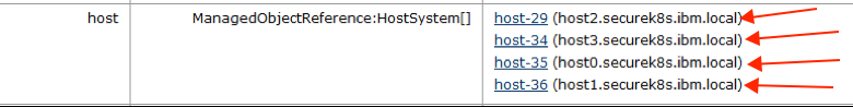
Click on the host that you need to validate. In our demo, we are checking host1.securek8s.ibm.local.
Search for method QueryTpmAttestationReport and click on it to invoke the method.
Click on Invoke Method.
5.2.6 Set up Active Directory users and groups
In this part of the setup, you will create several new organizational units. Remember that this procedure uses a Windows 2012 server and Microsoft AD to illustrate the steps. Your environment and your specific steps might be different. This section assumes actions are being performed from the ICSV Microsoft AD server. Alternatively, you can follow these steps to set up AD. Note that the values in the screen shots will be different than your values.
In Windows Server, start the Server Manager, if not already started.
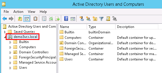
From the Server Manager window, select Tools -> Active Directory Users and Computers.
Right-click on your domain that has been created based on the instance name you provided by Windows AD deployment (for VCS) or during VCF deployment creation. For our demo, it is demo3VCS.local. Select New -> Organizational Unit. You should create the new OU.
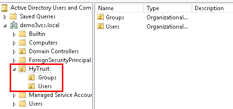
Enter HyTrust as the name of the new unit. Right-click on the HyTrust organizational unit, select New -> Organizational Unit, and give the name of Groups.
Right-click again on the HyTrust organizational unit, select New -> Organizational Unit, and give the name of Users. This group will be used to allow a user to communicate between HTCC and AD. The directory hierarchy should now look similar to this:
Add two users to the Users group. To do this, right-click on the HyTrust/Users organizational unit and select New -> User.
The first user is the primary user account that will be used to communicate between HTCC and AD. In the pop-up screen for users, enter user information as appropriate. The screen might look like this:
Full name: HyTrust LDAP Lookup
User logon name: ht_ldap_svc
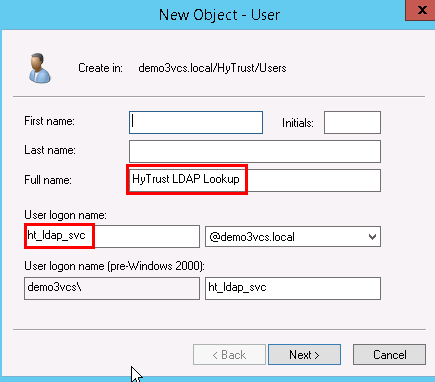
Click Next to go to the user password screen. It asks you to establish a password and some password options for the user. Enter or verify these fields:
Enter and confirm a password for the user. The password needs to have at least one upper case letter, otherwise the user will not be created. Note the password in the deployment spreadsheet.
Uncheck this option: User must change password at next logon.
Check this option: Password never expires.
Click Next
Verify the information and finish.
The second user will be used as the service account when HTCC interacts with vCenter. You could use the Administrator@vsphere.local account, but best practice is to create a specific service account in AD and use that. Create the second user (in the same way as the first user) with the following values:
Full name: HyTrust VCenter svc account
User logon name: ht_vcenter_svc
Ensure that the password never expires.
You will now create two subgroups under Groups.
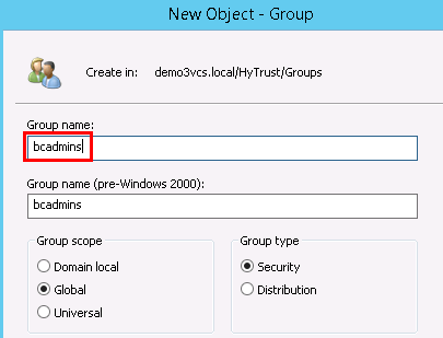
First, right-click on the Groups organizational unit and select New -> Group.
When prompted, enter a name for the new group: bcadmins. Later, you will tell HTDC to use this group when communicating with HTCC to verify boundary checks. Keep the rest of the options (Group scope and type) the default values as shown below. Press OK to create the group.
Right-click again on the Groups organizational unit and select New -> Group.
When prompted, enter a name for this group: ht_superadmin_users and press OK. Later, you will tell HTCC to use this group to specify administrative users of HTCC.
You will now add members to the superadmin group.
To do this, right-click on the ht_superadmin_users group, and select Properties.
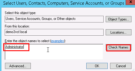
In the pop-up window, select the Members tab, then click Add.
In the next pop-up screen, enter an object name Administrator, and click on Check Names. If no error is returned, click OK.
Close the AD control panel.
You are now ready to set up HTCC authentication to work with AD, as described in the next procedure.
5.2.7 Join vCenter to the AD domain
We need to integrate the AD domain into vCenter so that we can later give the AD HyTrust service account vCenter permissions. You first have to join the vCenter to the AD domain, and then add the AD user to vCenter. Note that this is already done for VCS and VCF. However, you may want to check using the instructions below.
To check if vCenter is already joined to the AD domain, SSH into PSC.
Run the following command:
/opt/likewise/bin/domainjoin-cli queryIf the output indicates it’s already joined, you can skip the rest of this section (5.2.7).
If it’s not already joined, run the following command to join it:
/opt/likewise/bin/domainjoin-cli join <domain-name> <AD Administrator
user> <password>
Example:
/opt/likewise/bin/domainjoin-cli join demo3vcs.local Administrator
Passw0rd
Output:
Joining to AD Domain: demo3vcs.local
With Computer DNS Name: psc.demo3vcs.local
SUCCESS
Then reboot.
SSH into PSC again and verify that the join has succeeded by issuing the following command:
/opt/likewise/bin/domainjoin-cli query
5.2.8 Add AD HyTrust-vCenter service user to vCenter as Administrator
This is for both the VCS and VCF instances.
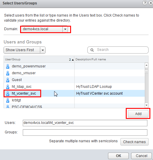
In the vSphere Web Client, go to Administration and then Users and Groups. Click on Groups, then Administrators, and select the Group Members Add icon.
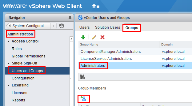
In the Add Principals panel, select the Windows AD Domain (demo.local in our example), scroll down and select the user ht_vcenter_svc user (that was created in Windows AD), and click on the Add button. That user should appear in the Users list. Then press the OK button.
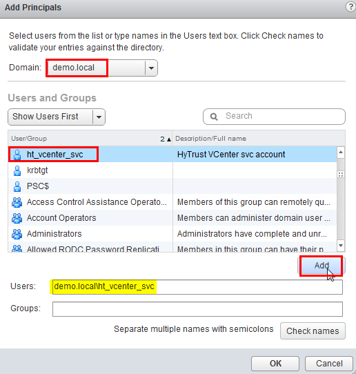
You have successfully added the Windows AD HyTrust vCenter LDAP id as part of the Administrator group. This id will be used for all interaction between HTCC and vCenter, when the vCenter is added to HTCC.
5.2.9 Add AD HyTrust-vCenter service user to vCenter Global Permissions
Go to the vCenter web client. Under Administration, click on Global Permissions.
Add the AD user for the HyTrust-vCenter service, ht_vcenter_svc, and give it Administration permission.
5.2.10 Configure HTCC for AD authentication
HTCC requires a directory services solution. In this deployment solution, HTCC authentication will be set up to work with Microsoft AD. Before you configure HTCC to use AD, you must define two groups and one user. You can do this via existing AD entries or create entries just for HTCC (as is the case in our implementation).
By default, HTCC is set to use a demo userid/password authentication. Once you change to AD authentication, you cannot revert back to the demo authentication.
If AD is configured with TLS, the AD server’s certificate must be imported into HTCC. To configure HTCC with an AD server with TLS configuration, refer to the HTCC Administration Guide for the following steps:
To import AD Server certificate into HTCC, refer to the HTCC Administration Guide section titled “Installing a Third-Party Root Certificate.”
Configure AD with TLS in HTCC. Refer to the HTCC Administration Guide section titled “Integrating the Appliance with Active Directory.”
To set up HTCC authentication, follow these steps:
Log onto the HTCC web console, using URL https://<HTCC-Virtual-IP>/asc with the default username of
superadminuserand the passwordPa$$w0rd123!From the HTCC dashboard, select the Configuration menu, and then Authentication.
Change the Authentication Server Type to Directory Service and accept your changes.
You should see a screen for configuring the service account. Make sure that the default domain name is the one you used to deploy the instance. In our demo, it’s demo3vcf.local. In the service account name field, enter the username (ht_ldap_svc) and password that you used during the AD setup steps.
Click Next, and you will see the domain listed. Click Next again.
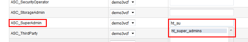
You should now see the Role-Group Mapping page. Look under the ASC_SuperAdmin section entry. Confirm that your AD domain is listed in the selected pull-down entry. In the group name field, enter the admin group name, ht_superadmin_users, that you created earlier in the initial AD setup. HTCC will attempt to perform predictive searches to allow for name completion.
Click Next and review the summary. If it is correct, finish. If AD is working correctly, the web interface will automatically log you out.
Log back in using the Administrator user and password of your Windows AD/DNS Server (which is the domain controller). Recall that we had added Administrator to the ht_superadmin_users group in Windows AD.
At this point, AD should be correctly set up for deployment. You are ready to set up the trust attestation service.
5.3 Add Hosts to HTCC and Enable Good Known Host (GKH)
You will add hosts in vCenter and then enable the Good Known Host (GKH) values to make them Trusted.
First, since all the hosts are managed by vCenter (as compared to standalone ESX hosts), you will add vCenter as the host—that will automatically detect the NSX server and the ESX hosts, and add them to HTCC. The high-level steps are:
In HTCC, add vCenter as the host. For vCenter, use the same AD LDAP used for the HTCC vCenter AD ID, ht_vcenter_svc@ibm.local (change the domain name based on what you have). While you can use Administrator@vsphere.local, best practice suggests you use the AD ID.
For all the ESX hosts that are detected, add their user IDs/passwords and Publish IPs.
If the vCenter and ESX host patch levels are not one of the valid patches supported by HTCC, add the patch level to HTCC so it recognizes them as valid hosts.
Next, follow the directions at Enabling a Good Known Host, then Verify and Update Host Trust.
Finally, to define, assign, and provision PolicyTags, follow these steps:
Assign PolicyTags to hosts. Important: We recommend that you put your host in maintenance mode before assigning PolicyTags, especially if you are modifying existing PolicyTag assignments which may be in use by your existing compliance rules. Do not remove the host from maintenance mode until you have verified that the new PolicyTag assignment has been correctly provisioned.
Select Compliance > Hosts.
On the Hosts page, check the checkbox for the Intel TXT-enabled host and click Edit.
On the Edit Hosts page, select the PolicyTag tab.
Select the appropriate PolicyTag value for one or more of the fields listed in Step 1.
Click OK.
CloudControl displays a JGrowl error message that prompts users to PXE boot the host(s) to activate the PolicyTag assignment.
Follow all of the PolicyTags provisioning directions in Section 4.3.1.
Verify the provisioning using these steps:
Open CloudControl and select Compliance > Hosts.
Select the host that you just updated and click Update Trust.
Select Policy > Resources.
Verify that the PolicyTags have been provisioned. If the tag icon next to the host being provisioned is blue, then the PolicyTags assigned to the host are provisioned. If the tag icon is yellow, then the PolicyTags assigned to the host are not provisioned. If the provisioning process was not successful, you may have to clear the TPM once again and repeat the process.
After the PolicyTag provisioning is successful, you can remove the hosts from maintenance mode.
6 Intel Product Installation and Configuration Guide
Intel TXT provides hardware-based security technologies that address the increasing and evolving security threats across physical and virtual infrastructures by complementing runtime protections. Intel TXT increases protection by allowing greater control of the launch stack through a Measured Launch Environment (MLE) and enabling isolation in the boot process. More specifically, it extends the Virtual Machine Extensions (VMX) environment of Intel Virtualization Technology (Intel VT), permitting a verifiably secure installation, launch, and use of a hypervisor or OS. These measured values in the boot process are extended to and stored in a TPM on the server.
To enable Intel TXT and the necessary TPM in the server BIOS, follow the steps in Section 5.2.3. The steps in Section 5.2.4 can be followed to verify that that each Dell ESXi host has successfully enabled the TPM and Intel TXT. The steps in Section 5.2.5 can be followed to verify that the Dell ESXi hosts’ TPM values are successfully read by the vCenter Server.
7 RSA Product Installation and Configuration Guide
This section covers the installation and configuration of the RSA products used to build the example solution.
7.1 RSA SecurID
RSA Authentication Manager is the authentication, administration, and database management component of RSA SecurID, which provides strong authentication of users accessing valuable network resources. Refer to RSA Authentication Manager 8.4 VMware Virtual Appliance Getting Started for installation instructions. Another source of information is Getting Started with RSA Authentication Manager.
Figure 7-1 represents a common RSA Authentication Manager deployment with primary and replica instances, web tiers, and a load balancer. An external firewall protects the primary and replica instances, and another external firewall protects the DMZ.
Figure 7‑1: RSA Authentication Manager Deployment Architecture
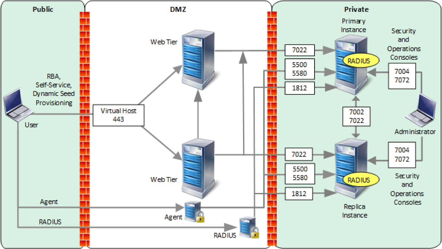
7.2 RSA NetWitness
To install and configure virtual hosts for RSA NetWitness Platform 11.4, follow the instructions in the Virtual Host Installation Guide. Start by reading the “Basic Virtual Deployment” section, then reading and following the steps in the “Install NetWitness Platform Virtual Host in Virtual Environment” section (except you can skip Step 1b).
The rest of this section explains how to configure NetWitness for VMware log collection from an ESX host.
7.2.1 Configure the VMware ESX/ESXi Event Source
This section describes how to create a least privilege user to extract logs from an ESX/ESXi host. You first create a role, then you create the user, and finally, you assign the role to the user.
Create a role as follows:
Log onto the ESXi host using the vSphere Client, with administrative privileges.
Click on Administration > Roles.
Click on Add Role.
Enter RSA Log Capture as the name of the Role.
Choose All Privileges > Global > Diagnostics as the only privilege for this role.
Create a local ESXi user as follows:
From the Left navigation pane, click on the ESXI host, then click the Users or Local Users & Groups tab. The name of the tab depends on the credentials you used to log onto the ESXi host.
Right-click on the Users tab, then click Add.
Enter rsa-vcenter-logs in the Login field, and choose a strong password.
Assign the role to the local user as follows:
From the Left navigation pane, click on the ESXI host, then click the Permissions tab.
Right-click in the Permissions table, then click Add Permission.
In the dialog box, under the Assigned Role drop-down menu, choose RSA Log Capture.
Under Users and Groups, click Add…. The Select Users and Groups dialog box is displayed.
In the dialog box, leave the Domain value as (server), and select the rsa-vcenter-logs user.
Click Add, then click OK.
This completes the process of adding a least privilege user. When you configure the Log Collector for VMware collection in RSA NetWitness Suite, make sure to enter the credentials for this user in the Add Source dialog box.
7.2.2 Configure the RSA NetWitness Log Collector for VMware Collection
To configure the RSA NetWitness Log Collection for VMware Collection, go to page 105 in the Log Collection Configuration Guide for RSA NetWitness Platform 11.4, and follow the instructions in the section titled “Configure VMware Event Sources in NetWitness Platform.”
8 VMware Product Installation and Configuration Guide
This section covers all the aspects of installing and configuring the VMware products used to build the example solution.
8.1 Prerequisites
The VMware Validated Design (VVD) is a blueprint for a Software Defined Data Center (SDDC). A Standard deployment model was used. In order to prepare for the implementation of the VVD, review the following documentation. It outlines the preparation and planning phases, contains logical design architectures and design decisions related to the implementation, and assists with the end-to-end process of deploying a VVD:
Documentation Structure and Audience (VVD 4.3, VVD 5.0.1), see Figure 8-1.
Architecture and Design
Planning and Preparation Deployment
Planning and Preparation Upgrade
Monitoring and Alerting
Backup and Restore
Site Protection and Recovery
Certificate Replacement
Operational Verification
IT Automating IT
Intelligent Operations
Security and Compliance Configuration for NIST 800-53:
Introducing VMware Validated Design for Software-Defined Data Center (VVD 4.3, VVD 5.0.1)
Design Objectives of VMware Validated Designs (VVD 4.3, VVD 5.0.1)
VMware Validated Design Architecture and Design (VVD 4.3, VVD 5.0.1)
VMware Validated Design Planning and Preparation (VVD 4.3, VVD 5.0.1)
VMware Validated Design for Software-Defined Data Center Release Notes (VVD 4.3, VVD 5.0, VVD 5.0.1)
To visualize how the VVD works in conjunction with the Compliance Kit for NIST 800-53, Figure 8-1 provides an overview of the documentation structure. The VMware Validated Design Compliance Kit enhances the documentation of the VVD for SDDC and must be applied after the SDDC is deployed.
Figure 8‑1: Map of VVD Documentation
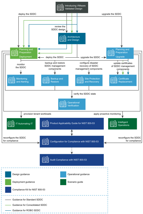
To reconfigure your SDDC for compliance with NIST SP 800-53 (https://doi.org/10.6028/NIST.SP.800-53r4), you must download and license additional VMware and third-party software.
The VVD coupled with Security and Compliance Configuration for NIST 800-53 uses scripts and commands based on VMware PowerCLI to reconfigure the SDDC. You must prepare a host with a supported OS for running Microsoft PowerShell, set up Microsoft PowerShell, and install the latest version of VMware PowerCLI. The host must have connectivity to the ESXi management network in the management cluster.
8.2 Installation and Configuration
Review the following documentation for the complete guide concerning the installation and configuration for the VVD for an SDDC for a Standard Deployment:
8.3 Configuration Customization Supporting the Use Cases and Security Capabilities
After deployment of a Standard VVD, the enhancements outlined in this publication should be applied. The security configurations and controls outlined in this section were implemented on a number of VVD versions, beginning with VVD 4.2 and then VVD 4.3. In addition to this lab, a separate project to publish the security configurations as a Compliance Kit that works as an enhancement to the VVD was published to VVD version 5.0.1. Changes between VVD 4.2, 4.3, 5.0.1, and even the most current version as of this writing, 5.1, are unlikely to have a significant impact to the configuration guidance.
Although this document outlines a specific version of the VVD, the Compliance Kit has been developed to support VVD 4.3, 5.0.1, 5.1, and future VVD releases. This section discusses the VMware Validated Design 5.0.1 Compliance Kit for NIST 800-53 and provides supplemental information detailing the resources that are included within the kit because the kit was not formally published for VVD 4.2 or 4.3, even though it was tested based on these versions. The VVD 5.0.1 Compliance Kit contains a number of files, including:
Introduction to Security and Compliance
Product Applicability Guide
Configuration Guide
Audit Guide
Audit Guide Appendix
The configuration procedures included within the kit are in two groups:
Built-In Controls: Security controls based on compliance requirements are included in the VVD for SDDC. These may require configuration and adjustment, but by design the capabilities are included in the VVD for SDDC.
Enhanced Controls: Additional guidance on a per regulation or standard basis includes a set of capabilities that can be added to the VVD for SDDC.
Over time, we expect a significant number of enhancement VVD controls to be incorporated into the VVD for SDDC. The enhancement guide always contains some number of NIST controls that are applicable to NIST SP 800-53 but are not included in the VVD for SDDC implementation. Each procedure documented in the Configuration Guide includes the NIST SP 800-53 control(s) that are associated with each. Two examples sampled from the Configuration Guide are included in Section 8.3.1 and Section 8.3.2.
Although the compliance kit was designed under VVD 5.0.1, the procedures and information included within the following sections are applicable to future releases of VVD, including VVD 5.1 and 5.1.1. Please note that while future iterations of the compliance kit will include configurations across all products, version 5.0.1 only corresponds to the following products: vCenter, ESXi, NSX for vSphere (NSX-V), and vSAN.
The following products are part of the VVD Bill of Materials, but not included in the current iteration of the Compliance Kit: vRealize, vRealize Automation (vRA), vRealize Operations Manager (vROPS), and vRealize Log Insight (vRLI). The documentation surrounding the configuration of these products does exist and is sourced from their respective DISA Security Technical Implementation Guides, which can be reviewed at https://public.cyber.mil/stigs/downloads. There are two examples for these configurations sampled from the Configuration Guide (Section 8.3.3 and Section 8.3.4).
8.3.1 Example VVD 5.0.1 Configuration: Configure the Password and Policy Lockout Setting in vCenter Server in Region A
In a web browser, log into vCenter by using the vSphere Web Client.
Configure the password policies.
From the Home menu of the vSphere Web Client, click Administration.
In the Navigator, under Single Sign-On, click Configuration.
On the Policies tab, under Password Policy, click Edit.
In the Edit Password Policies dialog box, configure the password policies and click OK.
Maximum Lifetime should be set to 60.
Restrict Reuse should be set to 5.
Minimum Length should be set to 15.
Upper-case Characters should be set to 1.
Lower-case Characters should be set to 1.
Numeric Characters should be set to 1.
Special Characters should be set to 1.
Configure the lockout policies.
On the Policies tab, click Lockout Policy and click Edit.
In the Edit Lockout Policy dialog box, for Maximum Number of Failed Login Attempts, enter 3.
For Interval Between Failures, enter 900.
For Unlock Time, enter 0 and then click OK.
8.3.2 Example VVD 5.0.1 Configuration: Configure Encryption Management in Region A
In a web browser, log in to vCenter Server by using the vSphere Web Client.
Enable Host Encryption Mode on the sfo01m01esx01.sfo01.rainpole.local host.
From the Home menu of the vSphere Web Client, select Hosts and Clusters.
Under the sfo01-m01dc data center, select the sfo01m01esx01.sfo01.rainpole.local host and click the Configure tab.
Under System, click Security profile.
Under Host Encryption Mode, click Edit.
In the Set Encryption Mode dialog box, from the Encryption Mode drop-down menu, select Enabled and click OK.
Repeat the procedure for all remaining hosts in Region A.
Enable VM encryption on all the VMs and virtual disks.
From the Home menu of the vSphere Web Client, select VMs and Templates.
Under the sfo01-m01dc data center, expand the sfo01-m01fd-bcdr folder, right-click the sfo01m01vc01 VM and select VM Policies, then Edit VM Storage Policies.
From the VM Storage Policy drop-down menu, select VM Encryption Policy, click Apply to all, and click OK.
Repeat the procedure to reconfigure the remaining VMs in Region A.
8.3.3 Example vRealize Automation DISA STIG Configuration: Configure SLES for vRealize to protect the confidentiality and integrity of transmitted information
Update the “Ciphers” directive with the following command:
sed -i "/^[^#]*Ciphers/ c\Ciphers aes256-ctr,aes128-ctr" /etc/ssh/sshd_configSave and close the file.
Restart the sshd process:
service sshd restart
8.3.4 Example vRealize Operations Manager DISA STIG Configuration: Configure the vRealize Operations server session timeout
Log on to the admin UI as the administrator.
Navigate to Global Settings.
Select Edit Global Settings.
Set the Session Timeout setting to 15 minutes.
Select OK.
8.4 Operation, Monitoring, and Maintenance
This section explains how to operate, monitor, and maintain various VMware products. It points to existing documentation whenever possible, so this document only includes supplemental information, such as backup and recovery processes, and specific monitoring practices recommended for the example solution.
8.4.1 Operation
This section discusses the basic operation of the VVD 5.0.1 for an SDDC, in addition to any relevant products associated with such operations.
vSphere vCenter Server (vCS) Appliance is a management application that allows for the management of VMs and ESXi hosts centrally. The vSphere Web Client is used to access the vCS.
vRealize Operations Manager (vROPS) tracks and analyzes the operation of multiple data sources in the SDDC by using specialized analytic algorithms. The algorithms help vROPS learn and predict the behavior of every object that it monitors. Users access this information by views, reports, and dashboards.
vRealize Automation (vRA) provides a secure web portal where authorized administrators, developers, and business owners can request new IT services and manage specific cloud and IT resources, while ensuring compliance with business policies.
Please review the following for further information and discussion pertaining to the operational standards of the VVD 5.0.1 for an SDDC: VMware Validated Design Documentation, VMware Validated Design 5.0.1 Compliance Kit for NIST 800-53, and NIST SP 1800-19B.
8.4.2 Monitoring
This section outlines monitoring and alerting functionalities and best practices pertaining to VVD.
Use the vRealize Log Insight (vRLI) event signature engine to monitor key events and to send filtered or tagged events to one or more remote destinations. You can use a set of alerts to send to vROPS and through SMTP for operations team notification. The use of vRLI allows you to monitor the SDDC and provide troubleshooting and cause analysis, which can reduce operating costs.
With the integration between vRLI and vROPS, you can implement the following cross-product event tracking:
Send alerts from vRLI to vROPS, which maps them to the target objects.
Launch in context from a vROPS object to the objects logs in vRLI.
Launch in context from a vRLI event to the objects in vROPS.
Use applications in vROPS to group monitoring data about the virtual machines of the SDDC management components.
vROPS builds an application to determine how your environment is affected when one or more components experience problems. You can also monitor the overall health and performance of the application.
vROPS collects data from the components in the application and displays the results in a summary dashboard with a real-time analysis for any or all the components.
Ensuring that your backup solution is configured to trigger an email alert generation showing the status of your backup jobs is a recommended practice within the SDDC. This should be included in daily monitoring activities to ensure that all management objects within the SDDC have successful backup images. The following can be done to enable broad monitoring using vROPS:
Create applications in vROPS to group the monitoring data
about the VMs of vRealize Suite Lifecycle Manager
about the VMs of vRLI
about the VMs of VMware Site Recovery Manager
about the VMs of VMware vSphere Replication (vR)
for the VMs of vROPS
collected from your vSphere Storage APIs for Data Protection (VADP)-based backup solution VMs
about the VMs of VMware vSphere Update Manager Download Service (UMDS)
Create email notifications in vROPS so it informs the SDDC operators of issues in the main monitoring parameters of the environment.
Configure vROPS to send email notifications about important alerts in the SDDC.
Please review the Monitoring and Alerting documentation for more information regarding the monitoring of the VVD 4.3 deployment, and the VVD for SDDC 5.0.1 release notes for more information on monitoring for VVD 5.0.1 deployments.
8.4.3 Maintenance
This section outlines the steps to perform an SDDC upgrade that follows a defined upgrade path. The NCCoE project started with VVD version 4.3 and upgraded to 5.0.1. Table 8-1 provides a summary of the system requirements and upgrade sequence associated with the Bill of Materials (BOM) or product versions associated with each VVD version. This upgrade path is functional and defined by layers in which the components are upgraded or updated. It is important to note that functional and scalability tests for individual patches and express patches are not required for an environment.
Table 8‑1: Summary of VVD Version and Associated Bill of Materials (Product Versions)
SDDC Layer |
Product Name |
Product Version in VVD 4.3 |
Product Version in VVD 5.0.1 |
Operation Type |
|---|---|---|---|---|
Operations Management |
vRealize Suite Lifecycle Manager |
1.2 |
2.0.0 Patch 2 |
Upgrade |
vRealize Log Insight |
4.6 |
4.7 |
Upgrade |
|
vRealize Log Insight Agent |
4.6 |
4.7 |
Upgrade |
|
vRealize Operations Manager |
6.7 |
7.0 |
Upgrade |
|
Cloud Management |
vRealize Business for Cloud |
7.4 |
7.5 |
Upgrade |
vRealize Automation with Embedded vRealize Orchestrator |
7.4 |
7.5 |
Upgrade |
|
Business Continuity |
Site Recovery Manager |
6.5.1.1 |
8.1.1 |
Upgrade |
vSphere Replication |
6.5.1.3 |
8.1.1 |
Upgrade |
|
Backup solution based on VMware vSphere Storage APIs for Data Protection |
Compatible Version |
Compatible Version |
Vendor Specific |
|
Virtual Infrastructure |
NSX Data Center for vSphere |
6.4.1 |
6.4.4 |
Update |
Platform Services Controller |
6.5 Update 2 |
6.7 Update 1 |
Upgrade |
|
vCenter Server |
6.5 Update 2 |
6.7 Update 1 |
Upgrade |
|
vSphere Update Manager Download Service |
6.5 Update 2 |
6.7 Update 1 |
Upgrade |
|
ESXi |
6.5 Update 2 |
6.7 Update 1 |
Upgrade |
|
vSAN |
6.6.1 Update 2 |
6.7 Update 1 |
Upgrade |
The following are tips for upgrading the SDDC:
Before you begin any upgrade process, review all the release notes.
Consider that the SDDC design and implementation may be affected by security features that are enabled. Ensure interoperability testing is performed before and after making security changes, as well as when introducing new features, functionality, and bug fixes.
The environment within the NCCoE lab varies from the conventional VVD deployment because for the NCCoE, additional integration with vendors is included, e.g., integration between HyTrust components and Key Management Server (KMS) and the VVD.
Note that if a distributed environment is used, ensure there is replication by using the vdcrepadmin command line interface between the platform services controller (PSC) and the vCenter environments. This can be checked by following the instructions in VMware Knowledge Base article 2127057.
Perform a backup copy of your current certificates before you start the upgrade process. If you need to request a new certificate, ensure you follow the procedures in this document for VVD 4.3 and this document for VVD 5.1.
The following is a tip for updating the SDDC:
Ensure an operational verification test is performed before and after performing an update. In most cases, updates should not impact the SDDC design and implementation (updates could include patches and bug fixes).
Updates that are not validated by VVD should be approached with caution.
Scalability and functionality tests for individual patches, express patches, and hot fixes are not typically performed using the VVD. If a patch must be applied to your environment, follow the VMware published practices and VMware Knowledge Base articles for the specific patch. If an issue occurs during or after the process of applying a patch, contact VMware Technical Support.
For further information and instruction regarding an update, please see the documentation for VVD 4.3 or VVD 5.0.
8.5 Product Configuration Overview
This section contains Table 8-2, which details all configurations for each product, their corresponding enhanced or built-in label, and their mapped NIST SP 800-53 Revision 4 controls (which are defined at https://doi.org/10.6028/NIST.SP.800-53r4). The labels are derived from the compliance kit with the exception of the vRA and vROPS items, which are sourced directly from their corresponding DISA STIGs.
There are only a small number of vROPS and vRA DISA STIGs included in the following table, which means it does not include all available configurations. For the entire compilation of vROPS and vRA DISA STIGs, please review the following links:
There are a few notable items for which there are no NIST control mappings; rather, they are identified as “VMware Best Practices”. These items are not sourced from any existing DISA STIGs, hardening guides, or other compliance frameworks. Their implementation is strongly recommended.
Table 8‑2: Configuration Items Without Control Mappings
Product Name |
Configuration Label |
Enhanced or Built-in |
NIST SP 800-53 Rev. 4 Controls |
|---|---|---|---|
ESXi |
NI ST80053-VI-ESXI-CFG-00048 |
Enhanced |
AC-12 |
ESXi |
NI ST80053-VI-ESXI-CFG-00146 |
Built-In |
AC-14a, AC-14b |
ESXi |
NI ST80053-VI-ESXI-CFG-00031 |
Enhanced |
AC-17 |
ESXi |
NI ST80053-VI-ESXI-CFG-00165 |
Built-In |
AC-7 |
ESXi |
NI ST80053-VI-ESXI-CFG-00002 |
Enhanced |
AC-8 |
NSX |
N IST80053-VI-NET-CFG-00343 |
Built-In |
CM-7 |
NSX |
N IST80053-VI-NET-CFG-00344 |
Built-In |
CM-7 |
NSX |
N IST80053-VI-NET-CFG-00372 |
Enhanced |
CP-9 |
NSX |
N IST80053-VI-NET-CFG-00374 |
Enhanced |
CP-9 |
NSX |
N IST80053-VI-NET-CFG-00312 |
Built-In |
IA-5 |
vCenter |
NIST80053-VI-VC-CFG-00453 |
Built-In |
VMware Best Practice only. No specific UCF_NIST_800_53_R4_High control is associated with this capability. |
vCenter |
NIST80053-VI-VC-CFG-00465 |
Built-In |
VMware Best Practice only. No specific UCF_NIST_800_53_R4_High control is associated with this capability. |
vCenter |
NIST80053-VI-VC-CFG-00442 |
Enhanced |
AU-5(2) |
vCenter |
NIST80053-VI-VC-CFG-00461 |
Built-In |
AU-9, AU-6a, AU-2d, AC-6(9) |
vCenter |
NIST80053-VI-VC-CFG-00460 |
Built-In |
AU-9, AU-7b, AU-7a, AU-7(1), AU-6a, AU-12c, AU-12a, AC-6(9) |
vRA |
VRAU-TC-000710 |
Enhanced |
AC-17 (1) |
vRA |
VRAU-VA-000010 |
Enhanced |
AC-17 (2) |
vRA |
VRAU-HA-000140 |
Enhanced |
CM-7a |
vRA |
VRAU-LI-000215 |
Enhanced |
CM-7a |
vRA |
VRAU-SL-000360 |
Enhanced |
IA-5 (1) (b) |
vRA |
VRAU-VI-000240 |
Enhanced |
IA-5 (1) (c) |
vRA |
VRAU-AP-000265 |
Enhanced |
IA-7 |
vRA |
VRAU-PG-000470 |
Enhanced |
SC-13 |
VROPS |
VROM-CS-000005 |
Enhanced |
AC-3 |
VROPS |
VROM-PG-000220 |
Enhanced |
IA-7 |
VROPS |
VROM-SL-001240 |
Enhanced |
SC-13 |
VROPS |
VROM-TC-000505 |
Enhanced |
SC-2 |
vSAN |
NIST80053 -VI-Storage-SDS-CFG-00182 |
Built-In |
AC-11a |
vSAN |
NIST80053 -VI-Storage-SDS-CFG-00186 |
Enhanced |
AU-4 |
vSAN |
NIST80053 -VI-Storage-SDS-CFG-00180 |
Built-In |
AU-8b, AU-8a, AU-8(1)(b), AU-8(1)(a) |
vSAN |
NIST80053 -VI-Storage-SDS-CFG-00181 |
Built-In |
AU-9, AU-7b, AU-7a, AU-7(1), AU-6a, AU-12c, AU-12a, AC-6(9) |
vSAN |
NIST80053 -VI-Storage-SDS-CFG-00183 |
Enhanced |
SC-13, MP-5(4), AU-9(3) |
vSphere |
NIST8 0053-VI-VSPHERE-CFG-00571 |
Enhanced |
CM-6 |
vSphere |
NIST8 0053-VI-VSPHERE-CFG-00563 |
Enhanced |
IA-2 |