NIST SPECIAL PUBLICATION 1800-19B
Trusted Cloud:
Security Practice Guide for VMware Hybrid Cloud Infrastructure as a Service (IaaS) Environments
Volume B:
Approach, Architecture, and Security Characteristics
Michael Bartock
Murugiah Souppaya
Computer Security Division
Information Technology Laboratory
Daniel Carroll
Robert Masten
Dell/EMC
Hopkinton, Massachusetts
Gina Scinta
Paul Massis
Gemalto
Austin, Texas
Hemma Prafullchandra*
Jason Malnar
HyTrust
Mountain View, California
Harmeet Singh
IBM
Armonk, New York
Raghuram Yeluri
Intel
Santa Clara, California
Tim Shea
Michael Dalton
RSA
Bedford, Massachusetts
Karen Scarfone
Scarfone Cybersecurity
Clifton, Virginia
Anthony Dukes
Carlos Phoenix
Brenda Swarts
VMware
Palo Alto, California
*Former employee; all work for this publication done while at employer
April 2022
FINAL
This publication is available free of charge from https://doi.org/10.6028/NIST.SP.1800-19
The draft publication is available free of charge from https://www.nccoe.nist.gov/publications/practice-guide/trusted-cloud-vmware-hybrid-cloud-iaas-environments-nist-sp-1800-19-draft

DISCLAIMER
Certain commercial entities, equipment, products, or materials may be identified by name or company logo or other insignia in order to acknowledge their participation in this collaboration or to describe an experimental procedure or concept adequately. Such identification is not intended to imply special status or relationship with NIST or recommendation or endorsement by NIST or NCCoE; neither is it intended to imply that the entities, equipment, products, or materials are necessarily the best available for the purpose.
While NIST and the NCCoE address goals of improving management of cybersecurity and privacy risk through outreach and application of standards and best practices, it is the stakeholder’s responsibility to fully perform a risk assessment to include the current threat, vulnerabilities, likelihood of a compromise, and the impact should the threat be realized before adopting cybersecurity measures such as this recommendation.
National Institute of Standards and Technology Special Publication 1800-19B, Natl. Inst. Stand. Technol. Spec. Publ. 1800-19B, 55 pages, (April 2022), CODEN: NSPUE2
FEEDBACK
As a private-public partnership, we are always seeking feedback on our practice guides. We are particularly interested in seeing how businesses apply NCCoE reference designs in the real world. If you have implemented the reference design, or have questions about applying it in your environment, please email us at trusted-cloud-nccoe@nist.gov.
All comments are subject to release under the Freedom of Information Act (FOIA).
NATIONAL CYBERSECURITY CENTER OF EXCELLENCE
The National Cybersecurity Center of Excellence (NCCoE), a part of the National Institute of Standards and Technology (NIST), is a collaborative hub where industry organizations, government agencies, and academic institutions work together to address businesses’ most pressing cybersecurity issues. This public-private partnership enables the creation of practical cybersecurity solutions for specific industries, as well as for broad, cross-sector technology challenges. Through consortia under Cooperative Research and Development Agreements (CRADAs), including technology partners—from Fortune 50 market leaders to smaller companies specializing in information technology security—the NCCoE applies standards and best practices to develop modular, adaptable example cybersecurity solutions using commercially available technology. The NCCoE documents these example solutions in the NIST Special Publication 1800 series, which maps capabilities to the NIST Cybersecurity Framework and details the steps needed for another entity to re-create the example solution. The NCCoE was established in 2012 by NIST in partnership with the State of Maryland and Montgomery County, Maryland.
NIST CYBERSECURITY PRACTICE GUIDES
NIST Cybersecurity Practice Guides (Special Publication Series 1800) target specific cybersecurity challenges in the public and private sectors. They are practical, user-friendly guides that facilitate the adoption of standards-based approaches to cybersecurity. They show members of the information security community how to implement example solutions that help them align with relevant standards and best practices, and provide users with the materials lists, configuration files, and other information they need to implement a similar approach.
The documents in this series describe example implementations of cybersecurity practices that businesses and other organizations may voluntarily adopt. These documents do not describe regulations or mandatory practices, nor do they carry statutory authority.
ABSTRACT
A cloud workload is an abstraction of the actual instance of a functional application that is virtualized or containerized to include compute, storage, and network resources. Organizations need to be able to monitor, track, apply, and enforce their security and privacy policies on their cloud workloads, based on business requirements, in a consistent, repeatable, and automated way. The goal of this project is to develop a trusted cloud solution that will demonstrate how trusted compute pools leveraging hardware roots of trust can provide the necessary security capabilities. These capabilities not only provide assurance that cloud workloads are running on trusted hardware and in a trusted geolocation or logical boundary, but also improve the protections for the data in the workloads and in the data flows between workloads. The example solution leverages modern commercial off-the-shelf technology and cloud services to address lifting and shifting a typical multi-tier application between an organization-controlled private cloud and a hybrid/public cloud over the internet.
KEYWORDS
cloud technology; compliance; cybersecurity; privacy; trusted compute pools
ACKNOWLEDGMENTS
The Technology Partners/Collaborators who participated in this build submitted their capabilities in response to a notice in the Federal Register. Respondents with relevant capabilities or product components were invited to sign a Cooperative Research and Development Agreement (CRADA) with NIST, allowing them to participate in a consortium to build this example solution. We worked with:
Technology Partner/Collaborator |
Build Involvement |
|---|---|
Server, storage, and networking hardware |
|
Hardware security module (HSM) for storing keys |
|
Asset tagging and policy enforcement, workload and storage encryption, and data scanning |
|
Public cloud environment with IBM-provisioned servers |
|
Intel processors in the Dell EMC servers |
|
Multifactor authentication, network traffic monitoring, and dashboard and reporting |
|
Compute, storage, and network virtualization capabilities |
DOCUMENT CONVENTIONS
The terms “shall” and “shall not” indicate requirements to be followed strictly to conform to the publication and from which no deviation is permitted. The terms “should” and “should not” indicate that among several possibilities, one is recommended as particularly suitable without mentioning or excluding others, or that a certain course of action is preferred but not necessarily required, or that (in the negative form) a certain possibility or course of action is discouraged but not prohibited. The terms “may” and “need not” indicate a course of action permissible within the limits of the publication. The terms “can” and “cannot” indicate a possibility and capability, whether material, physical, or causal.
PATENT DISCLOSURE NOTICE
NOTICE: The Information Technology Laboratory (ITL) has requested that holders of patent claims whose use may be required for compliance with the guidance or requirements of this publication disclose such patent claims to ITL. However, holders of patents are not obligated to respond to ITL calls for patents and ITL has not undertaken a patent search in order to identify which, if any, patents may apply to this publication.
As of the date of publication and following call(s) for the identification of patent claims whose use may be required for compliance with the guidance or requirements of this publication, no such patent claims have been identified to ITL.
No representation is made or implied by ITL that licenses are not required to avoid patent infringement in the use of this publication.
List of Figures
Figure 4‑1 High-Level Solution Architecture
Figure 4‑2 High-Level NCCoE Cloud Architecture
Figure 4‑3 VMware Management Cluster Architecture
Figure 4‑4 VMware Compute Cluster Architecture
Figure 4‑6 HSM Architecture in the NCCoE Cloud
Figure 4‑7 HyTrust Architecture in the NCCoE Cloud
Figure 4‑8 HTKC Node Deployments
Figure 4‑9 NCCoE Layer 3 Leaf – Spine Logical Network Diagram
Figure 4‑10 IBM Cloud Architecture
Figure 5‑1 Example of Secure Configuration Scan Results
Figure 5‑2 Examples of Trusted Compute Nodes
Figure 5‑3 Example of Decrypted Workload
Figure 5‑4 Example of Workload on Untagged Server
Figure 5‑5 Example of Workload that Cannot Be Decrypted
Figure 5‑6 Example of Workload Migrated to Trusted and Tagged Server
Figure 5‑7 Example of Workload Running on Trusted and Tagged Server
List of Tables
Table 3‑1 Common Threats Associated with Hybrid Cloud Usage
Table 4‑1 Products and Technologies Summary
Table A‑1 List of NIST SP 800-53 Revision 5 Controls Addressed by Solution
Table A‑2 List of NIST Cybersecurity Framework Subcategories Addressed by Solution
1 Summary
Building on previous work documented in National Institute of Standards and Technology (NIST) Internal Report (NISTIR) 7904, Trusted Geolocation in the Cloud: Proof of Concept Implementation [B1], the goal of the project is to expand upon the security capabilities provided by trusted compute pools in a hybrid cloud model, including the following capabilities:
single pane of glass for the management and monitoring of cloud workloads, including software configurations and vulnerabilities
data protection and encryption key management enforcement focused on trust-based and geolocation-based/resource pools, and secure migration of cloud workloads
key management and keystore controlled by the organization, not the cloud service provider
persistent data flow segmentation before and after the trust-based and geolocation-based/resource pools secure migration
industry sector and/or organizational business compliance enforcement for regulated workloads between the on-premises private and hybrid/public clouds
These additional capabilities not only provide assurance that cloud workloads are running on trusted hardware and in a trusted geolocation or logical boundary, but also improve the protections for the data in the workloads and in the data flows between workloads.
1.1 Challenge
Cloud services can provide organizations, including federal agencies, with the opportunity to increase the flexibility, availability, resiliency, and scalability of cloud services, which the organizations can, in turn, use to increase security, privacy, efficiency, responsiveness, innovation, and competitiveness. However, many organizations, especially those in regulated sectors like finance and healthcare, face additional security and privacy challenges when adopting cloud services.
Cloud platform hardware and software are evolving to take advantage of the latest hardware and software features, and there are hundreds or thousands of virtualized or containerized workloads that are spun up, scaled out, moved around, and shut down at any instant, based on business requirements. In such environments, organizations want to be able to monitor, track, apply, and enforce policies on the workloads, based on business requirements, in a consistent, repeatable, and automated way. In other words, organizations want to maintain consistent security protections and to have visibility and control for their workloads across on-premises private clouds and third-party hybrid/public clouds in order to meet their security and compliance requirements.
This is further complicated by organizations’ need to comply with security and privacy laws applicable to the information that they collect, transmit, or hold, which may change depending on whose information it is (e.g., European citizens under the General Data Protection Regulation), what kind of information it is (e.g., health information compared to financial information), and in what state or country the information is located. Additionally, an organization must be able to meet its own policies by implementing appropriate controls dictated by its risk-based decisions about the necessary security and privacy of its information.
Because laws in one location may conflict with an organization’s policies or mandates, an organization may decide that it needs to restrict the type of cloud servers it uses, based on the state or country. Thus, the core impediments to broader adoption of cloud technologies are the abilities of an organization to protect its information and virtual assets in the cloud, and to have sufficient visibility into that information so that it can conduct oversight and ensure that it and its cloud provider are complying with applicable laws and business practices.
In addition, there are technical challenges and architectural decisions that have to be made when connecting two disparate clouds. An important consideration revolves around the type of wide area network connecting the on-premises private cloud and the hybrid/public cloud, because it may impact the latency of the workloads and the security posture of the management plane across the two infrastructures.
1.2 Solution
The project involves collaborating with industry partners to design, engineer, and build solutions leveraging commercial off-the-shelf technology and cloud services to deliver a trusted cloud implementation. This implementation will allow organizations in regulated industries to leverage the flexibility, availability, resiliency, and scalability of cloud services while complying with applicable requirements, such as the Federal Information Security Modernization Act (FISMA), the Payment Card Industry Data Security Standard (PCI DSS), and the Health Insurance Portability and Accountability Act (HIPAA), as well as industry-neutral voluntary frameworks like the NIST Cybersecurity Framework. The technology stack includes modern hardware and software that can be leveraged to support the described use cases and ease the adoption of cloud technology.
The example implementation is for a hybrid cloud use case, enabling an organization to lift and shift a typical multi-tier application between a private cloud stack located in the National Cybersecurity Center of Excellence (NCCoE) data center and the IBM public cloud over the public internet.
1.3 Benefits
Organizations will be able to maintain consistent security and privacy protections for information across cloud platforms; dictate how different information is protected, such as having stronger protection for more‑sensitive information; and retain visibility into how their information is protected, to ensure consistent compliance with legal and business requirements.
Technical staff will learn how to utilize commercial off-the-shelf technology and cloud services to achieve trusted cloud implementations that protect cloud workloads and support compliance initiatives.
Senior management and information security officers will be motivated to use trusted cloud technologies.
2 How to Use This Guide
This NIST Cybersecurity Practice Guide demonstrates a standards-based reference design and provides users with the information they need to replicate the trusted compute pools in a hybrid cloud model that provide expanded security capabilities. This reference design is modular and can be deployed in whole or in part.
This guide contains three volumes:
NIST Special Publication (SP) 1800-19A: Executive Summary
NIST SP 1800-19B: Approach, Architecture, and Security Characteristics – what we built and why (you are here)
NIST SP 1800-19C: How-To Guides – instructions for building the example solution
Depending on your role in your organization, you might use this guide in different ways:
Business decision makers, including chief security and technology officers, will be interested in the Executive Summary, NIST SP 1800-19A, which describes the following topics:
challenges enterprises face in protecting cloud workloads in hybrid cloud models
example solution built at the NCCoE
benefits of adopting the example solution
Technology or security program managers who are concerned with how to identify, understand, assess, and mitigate risk will be interested in this part of the guide, NIST SP 1800-19B, which describes what we did and why. The following sections will be of particular interest:
Section 3.4.3, Risk, provides a description of the risk analysis we performed
Appendix A, Mappings, maps the security characteristics of this example solution to cybersecurity standards and best practices
You might share the Executive Summary, NIST SP 1800-19A, with your leadership team members to help them understand the importance of adopting standards-based trusted compute pools in a hybrid cloud model that provide expanded security capabilities.
Information technology (IT) professionals who want to implement an approach like this will find the whole practice guide useful. You can use the how-to portion of the guide, NIST SP 1800-19C, to replicate all or parts of the build created in our lab. The how-to portion of the guide provides specific product installation, configuration, and integration instructions for implementing the example solution. We do not re-create the product manufacturers’ documentation, which is generally widely available. Rather, we show how we incorporated the products together in our environment to create an example solution.
This guide assumes that IT professionals have experience implementing security products within the enterprise. While we have used a suite of commercial products to address this challenge, this guide does not endorse these particular products. Your organization can adopt this solution or one that adheres to these guidelines in whole, or you can use this guide as a starting point for tailoring and implementing parts of a trusted cloud implementation leveraging commercial off-the-shelf technology. Your organization’s security experts should identify the products that will best integrate with your existing tools and IT system infrastructure. We hope that you will seek products that are congruent with applicable standards and best practices. Section 4.2, Technologies, lists the products we used and maps them to the cybersecurity controls provided by this reference solution.
A NIST Cybersecurity Practice Guide does not describe “the” solution, but a possible solution. Comments, suggestions, and success stories will improve subsequent versions of this guide. Please contribute your thoughts to trusted-cloud-nccoe@nist.gov.
2.1 Typographical Conventions
The following table presents typographic conventions used in this volume.
Typeface/ Symbol |
Meaning |
Example |
|---|---|---|
Italics |
file names and path names; references to documents that are not hyperlinks; new terms; and placeholders |
For language use and style guidance, see the NCCoE Style Guide. |
Bold |
names of menus, options, command buttons, and fields |
Choose File > Edit. |
Monospace |
command-line input, onscreen computer output, sample code examples, and status codes |
|
Monospace (block) |
multi-line input, on-screen computer output, sample code examples, status codes |
% mkdir -v nccoe_projects
mkdir: created directory 'nccoe_projects'
|
blue text |
link to other parts of the document, a web URL, or an email address |
All publications from NIST’s NCCoE are available at https://www.nccoe.nist.gov. |
3 Approach
The NCCoE invited technology providers to participate in demonstrating a proposed approach for implementing trusted resource pools leveraging commercial off-the-shelf technology and cloud services to aggregate trusted systems and segregate them from untrusted resources. This would result in the separation of higher-value, more‑sensitive workloads from commodity application and data workloads in an infrastructure as a service (IaaS) deployment model. In this project, the example implementation involves securely migrating—“lifting and shifting”—a multi-tier application from an organization-controlled private cloud to a hybrid/public cloud over the internet. The implementation automatically, and with assurance, restricts cloud workloads to servers meeting selected characteristics. It also provides the ability to determine the security posture of a cloud workload at any time through continuous monitoring, no matter the cloud or the cloud server.
The NCCoE prepared a Federal Register notice [B2] seeking technology providers to provide products and/or expertise to compose prototypes that include commodity servers with hardware cryptographic modules; commodity network switches; hypervisors; operating systems (OSs); application containers; attestation servers; orchestration and management servers; database servers; directory servers; software-defined networks; data encryption and key management servers; and cloud services. Cooperative Research and Development Agreements (CRADAs) were established with qualified respondents, and “build teams” were assembled.
The following actions were performed by the build teams:
fleshing out the initial architecture and composing the collaborators’ components into demonstration prototypes
documenting the architecture and design implementation, including the steps taken to install and configure each component of the demonstration environment
conducting security and functional testing of the demonstration environment, and then conducting and documenting the results of a risk assessment and a security characteristics analysis
working with industry collaborators to suggest future considerations
3.1 Audience
This guide is intended for cloud computing practitioners, system integrators, IT managers, security managers, IT architects, and others interested in practical, effective implementations of trusted cloud technologies that can reduce risk and satisfy existing system security requirements.
3.2 Scope
The scope of this project is the usage of hybrid/public clouds and on-premises private clouds to securely host an organization’s own workloads in an IaaS deployment model. The project is intended to be particularly useful to organizations in regulated industries, but it should be of use to organizations in any industry and sector.
3.3 Assumptions
This project is guided by the following assumptions:
Organizations implementing this solution are responsible for providing core infrastructure services, including Microsoft Active Directory, certificate services, Domain Name System (DNS), Dynamic Host Configuration Protocol (DHCP), Network Time Protocol (NTP), Simple Mail Transfer Protocol (SMTP), Simple Network Management Protocol (SNMP), and logging services.
Organizations should already have their physical infrastructure configured to be fault tolerant.
Organizations should work with their cloud service provider, legal team, and others as needed to have the necessary agreements in place regarding responsibilities.
Federal agencies will need to choose hybrid/public clouds that are Federal Risk and Authorization Management Program (FedRAMP) certified. Other industry sectors should follow their sector-specific cloud service certification program.
Organizations will need to implement and manage all security controls that their cloud service provider is not formally responsible for implementing and maintaining on their behalf.
Organizations will need to ensure that the VMware Validated Design meets their requirements for availability, manageability, performance, recoverability, and security.
Organizations will need to ensure that they have identified all applicable compliance requirements.
Organizations should have trained and qualified staff to architect, secure, and operate the solution stack.
3.4 Risk Assessment
NIST SP 800-30 Revision 1, Guide for Conducting Risk Assessments states that risk is “a measure of the extent to which an entity is threatened by a potential circumstance or event, and typically a function of: (i) the adverse impacts that would arise if the circumstance or event occurs; and (ii) the likelihood of occurrence.” The guide further defines risk assessment as “the process of identifying, estimating, and prioritizing risks to organizational operations (including mission, functions, image, reputation), organizational assets, individuals, other organizations, and the Nation, resulting from the operation of an information system. Part of risk management incorporates threat and vulnerability analyses, and considers mitigations provided by security controls planned or in place.” [B3]
The NCCoE recommends that any discussion of risk management, particularly at the enterprise level, begin with a comprehensive review of NIST SP 800-37 Revision 2, Risk Management Framework for Information Systems and Organizations [B4] for the United States (U.S.) government public sector; private-sector risk management frameworks (RMFs), such as International Organization for Standardization (ISO) 31000 [B5], Committee of Sponsoring Organizations of the Treadway Commission (COSO) Enterprise Risk Management – Integrating with Strategy and Performance (2017) [B6], and Factor Analysis of Information Risk (FAIR) [B7]; or sector-agnostic frameworks, such as the NIST Cybersecurity Framework [B8] — material that is available to the public. The Risk Management Framework (RMF) guidance, as a whole, proved to be invaluable in giving us a baseline to assess risks, from which we developed the project, the security characteristics of the build, and this guide.
3.4.1 Threats
Table 3-1 lists examples of common threats associated with the hybrid cloud usage scenario of this project, where two clouds under the control of different providers are linked together so that workloads can be moved between them. This list of threats is not meant to be comprehensive.
Table 3‑1 Common Threats Associated with Hybrid Cloud Usage
Threat/Attack Type |
Example |
Addressed by Solution |
|---|---|---|
Threats Against Cloud Infrastructure |
||
Physical threat against data center (e.g., natural disaster, cooling system failure) |
A regional power outage necessitates shutting down servers at one data center location. |
Have adequate environmental controls in place for the data center, such as backup power, heating and cooling mechanisms, and fire detection and suppression systems. Be prepared to automatically shift workloads to another suitable location at any time. The enterprise data center infrastructure team or cloud service operators are responsible for providing these mechanisms. |
Tampering with server firmware (e.g., Basic Input/Output System [BIOS]) |
An unapproved change management control or a malicious insider gains physical access to a server in the data center and alters its BIOS configuration to disable its security protections. |
Use physical security controls to restrict data center access to authorized personnel only. Monitor data center access at all times. Detect changes by taking an integrity measurement of the BIOS at boot and comparing it with a previous measurement taken in a “clean room” environment and configured as a good known BIOS. |
Threats Against Cloud Management |
||
Tampering with a virtual machine manager (VMM) |
An unapproved change management control, a malicious insider, or an external attacker with stolen administrator credentials reuses them to gain access to the VMM and install malicious code. |
Detect changes to the VMM by taking an integrity measurement of the kernel and specific vSphere Installation Bundles (VIBs) at boot and comparing it with previous measurements taken in a “clean room” environment and configured as a good known host (GKH). |
Unauthorized administrator-level or service-level access |
An external attacker steals an administrator account password and reuses it to gain access to a file. |
Enforce strong authentication, including two-factor authentication with a cryptographic token, for all administrative and service access to cloud workloads, VMMs, and other management systems. Allow only administrators to manage the systems they have a need to administer by enforcing least privilege and separation of duties. Monitor the use of administrator and service credentials at all times, log all access attempts, and alert when suspicious activity is observed. |
Administrative changes (accidental or malicious) that are destructive |
An administrator accidentally deletes a virtualized domain controller. |
Enforce secondary approval workflow for specific assets and/or administrative operations to implement the “four-eyes” principle for highly sensitive systems and/or operations. |
Intentional or accidental configuration changes that violate hardening best practices |
Upgrading an authorized application inadvertently wipes out existing application configuration settings. |
Continuously monitor all configuration changes on all components. Run regularly scheduled assessments and remediations with customized hardening templates to remain in compliance with configuration hardening best practices. |
Unauthorized access to secret cryptographic keys |
An attacker takes advantage of a weak key management protocol implementation to intercept unprotected keys being distributed to virtual machines (VMs). |
Provide Federal Information Processing Standard (FIPS) 140-validated, Key Management Interoperability Protocol (KMIP)-compliant key management services for cryptographic functions that operate in a hardware security module (HSM) to safeguard sensitive key materials. |
Threats Against Cloud Workload Storage, Execution, and Use |
||
Running a cloud workload within an untrusted environment or location |
A cloud administrator may respond to an impending maintenance disruption by moving workloads to cloud servers in other locations. |
Allow cloud workloads to execute only on a physical server that is known to be good (i.e., not tampered with) and is within an authorized geolocation. |
Unauthorized access from one workload to another within a cloud |
A user of one workload connects to another organization’s workload and exploits vulnerabilities in it to gain unauthorized access. |
Establish network boundaries through dedicated virtual local area networks (VLANs) leveraging automated access control lists (ACLs). Use Institute of Electrical and Electronics Engineers (IEEE) 802.1Q VLAN tagging for network traffic within the cloud data center so that only traffic tagged with a server’s unique VLAN identifier is routed to or from that server. |
Unauthorized movement within the cloud environment from a compromised cloud workload (e.g., lateral movement) |
A cloud workload is compromised, and the attacker has full privileged access to the system. The attacker tries to move laterally to discover sensitive resources and escalate privileges to gain greater access to the environment. |
Use software-defined technology and user privilege segmentation to allowlist the network communications and access rights. |
Intentional or accidental exposure of sensitive data |
An administrator copies a cloud workload file to an unauthorized location. |
Encrypt cloud workloads at rest. Use end-to-end encryption with mutual authentication when moving a workload from one location to another. |
Unauthorized access to files containing sensitive data |
A malicious insider misuses OS access to copy a file. |
Scan filesystems for sensitive data, categorize the discovered files, monitor all access to those files, and report on that access. Enforce access controls that prevent different cloud provider administrators of workloads from accessing sensitive applications and data drives. |
3.4.2 Vulnerabilities
The primary areas of concern are software flaws and misconfigurations at all levels of the architecture: low-level services (compute, storage, network), VMMs, OSs, and applications, including cloud workload management, VMM management, and other management tools. Related to these concerns is the need to ensure that the same security policies are being enforced within both clouds for the workloads to eliminate some vulnerabilities and mitigate others.
Some examples of vulnerabilities that might be particularly impactful if exploited are listed below:
cryptographic keys being stored or transmitted without being strongly encrypted
cloud workloads being migrated without performing mutual authentication of the clouds or verifying the integrity of the migrated workload
weak administrator or service account credentials that are highly susceptible to theft and unauthorized reuse
access controls that do not enforce the principles of least privilege and separation of duties
3.4.3 Risk
The proposed solution implements several layers of controls to protect workloads while they reside within clouds and while they are migrated from one cloud to another. The cloud workloads are still vulnerable. For example, an unknown software flaw in a cloud workload’s software, or in the VMM underlying that workload, could be exploited, potentially compromising the workload itself. There are always residual risks for cloud workloads. The proposed solution includes only technical controls; therefore, risk involving the solution’s physical environment, people (e.g., users, administrators), processes, and other non-technical items will also need to be addressed.
4 Architecture
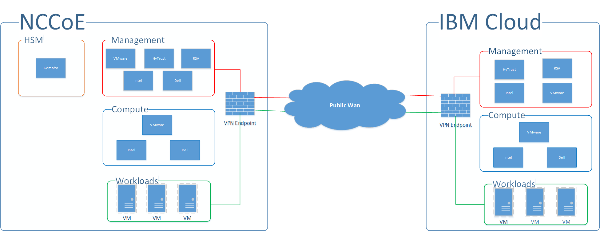
At a high level, the trusted cloud architecture has three main pieces: a private cloud hosted at the NCCoE, an instance of the public IBM Cloud Secure Virtualization (ICSV), and an Internet Protocol Security (IPsec) virtual private network (VPN) that connects the two clouds to form a hybrid cloud. Figure 4-1 provides a simplified diagram of the architecture.
The private on-premises cloud at the NCCoE consists of the following components:
HSM for storing keys by Gemalto
server, storage, and networking hardware by Dell EMC
Intel processors in the Dell EMC servers
compute, storage, and network virtualization capabilities by VMware
asset tagging and policy enforcement, workload and storage encryption, and data scanning by HyTrust
multifactor authentication, network traffic monitoring, and dashboard and reporting by RSA
The ICSV instance consists of the following components:
IBM-provisioned servers with Intel processors
compute, storage, network virtualization with VMware components
asset tagging and policy enforcement, and workload and storage encryption with HyTrust components
The IPSec VPN established between the two clouds allows them to be part of the same management domain so that each component can be managed and utilized in the same fashion, which creates one hybrid cloud. The workloads can be shifted or live-migrated between the two sites.
Figure 4‑1 High-Level Solution Architecture
4.1 Architecture Components
Within the high-level architecture, there are four main components that comprise the trusted cloud build:
HSM component: This build utilizes HSMs to store sensitive keys within the environment. One set of HSMs is used for the domain’s root and issuing Transport Layer Security (TLS) certificate authorities (CAs), while another HSM is used to protect keys that are used to encrypt workloads. The HSM component is deployed in the private cloud at the NCCoE, and network access is strictly limited to only the machines that need to communicate with it.
Management component: The identical functional management components are instantiated across the NCCoE private cloud and the ICSV public cloud instance. The single management console is used to operate the virtual infrastructure hosting the tenant workloads. At a minimum, each management component consists of hardware utilizing Intel processors, VMware running the virtualization stack, HyTrust providing the asset tagging policy enforcement aspect, and RSA providing network-visibility, dashboard, and reporting capabilities. The management components on each site are connected through the IPsec VPN to represent one logical management element.
Compute component: Both sites of the hybrid cloud include similar compute components. The compute components host the tenant workload VMs. Asset tagging is provisioned on the compute servers so that policy can be assigned and enforced to ensure that tenant workloads reside on servers that meet specific regulatory compliance requirements. At a minimum, each compute component consists of hardware utilizing Intel processors and VMware running the virtualization stack. The compute components on each site are connected through the IPsec VPN so that workloads can be migrated between the two sites.
Workload component: Both sites of the hybrid cloud have similar workload components. The workload components include VMs, data storage, and networks owned and operated by the tenant and data owner. Policies are applied to the workloads to ensure that they can run only on servers that meet specific requirements, such as asset tag policies.
4.2 Technologies
We built the proposed solution by using products from vendors who have established CRADAs with the NCCoE for this project. The NCCoE does not endorse or recommend these products. Each organization should determine if these products, or other products on the market with similar capabilities, best meet your own requirements and integrate well with your existing IT system infrastructure.
The following subsections describe the vendors and products that we used for our example solution.
4.2.1 Dell EMC
Dell EMC has developed a keen focus on building security into the product design versus bolting on security after release. For this solution, Dell EMC provided enterprise and in-rack networking solutions, Dell PowerEdge Servers to provide compute capabilities, and Dell EMC Unity unified storage for the primary storage solutions.
Dell Networking solutions utilizing the OS9 OS and the Dell PowerEdge servers have gone through rigorous testing and approval processes to be published on the Defense Information Systems Agency (DISA) Approved Products List. This includes the inclusion of the Integrated Dell Remote Access Controller, Lifecycle Controller, and connectivity to the OpenManage solution. This capability allows for enterprise standardization of platform and switch configurations to enable NIST SP 800-53 security controls [B9].
Dell EMC Unity provides a robust unified storage solution with built-in security configuration that allows for a simple enablement of platform hardening to meet DISA Security Technical Implementation Guide (STIG) standards. The Dell EMC Unity solution OS is based on a derivative of SUSE Linux 12. Dell EMC, in collaboration with DISA, performed extensive testing and development to ensure that Dell EMC Unity meets the high standards that DISA has established for its Approved Product Listing.
Dell EMC provided implementation and consulting services to ensure that these components of the overall solution were implemented to meet the proof-of-concept guidelines for a highly secured infrastructure.
4.2.2 Gemalto
Gemalto’s Enterprise and Cybersecurity business unit focuses on providing solutions for the encryption of data at rest and data in motion, secure storage and management of encryption keys through the use of HSMs and centralized key management, and controlling access by using multifactor authentication and identity access management across cloud, virtual, and on-premises environments.
SafeNet Hardware Security Modules provide the highest level of security by always storing cryptographic keys in hardware. SafeNet HSMs provide a secure cryptographic foundation, as the keys never leave the intrusion-resistant, tamper-evident, FIPS-validated appliance. Because all cryptographic operations occur within the HSM, strong access controls prevent unauthorized users from accessing sensitive cryptographic material.
The SafeNet Luna Universal Serial Bus (USB) HSM is a small form-factor USB-attached HSM that is used as a root of trust for storing root cryptographic keys in an offline key storage device.
The SafeNet Luna Network HSM (Versions 6 and 7) is a network-attached HSM protecting encryption keys used by applications in on-premises, virtual, and cloud environments. The HSM has more than 400 integrations. For this project, SafeNet Luna Network HSM 7 is the root of trust for Microsoft Active Directory Certificate Services (ADCS) used to issue TLS certificates. SafeNet Luna Network HSM 6 is integrated as the root of trust for HyTrust KeyControl (HTKC) via the KMIP key management service.
The SafeNet Backup HSM ensures that sensitive cryptographic material remains strongly protected in hardware, even when not being used. You can back up and duplicate keys securely to the SafeNet Backup HSM for safekeeping in case of emergency, failure, or disaster.
4.2.3 HyTrust
HyTrust helps make cloud infrastructure more trustworthy for those organizations pursuing a multi-cloud approach by delivering a critical set of capabilities required to proactively secure workloads wherever they reside. The HyTrust Cloud Security Policy Framework (CloudSPF) allows organizations to automate the creation, application, and enforcement of security and compliance policies for private, hybrid, and public cloud workloads, including three critical attributes of the workload—people, data, and infrastructure. HyTrust CloudSPF is supported by a portfolio of five solutions that deliver the functionality needed to enable policy-driven security and automated compliance of workloads in multi-cloud environments—including securing data and ensuring data privacy, preventing privileged admin misuse, automating compliance tasks, securing multi-tenant environments, and more. The five solutions are as follows:
HyTrust CloudControl (HTCC): Workload Security Policy Enforcement and Compliance: Key capabilities help organizations protect their virtualized infrastructures with authentication, authorization, and auditing. Better visibility and control simplify compliance and accelerate further virtualization and data center transformation. CloudControl functionality includes two-factor authentication, secondary approval workflows, advanced role-based and object-based access controls, audit-quality logging, and hypervisor hardening.
HyTrust DataControl (HTDC): Workload Encryption and Integrated Key Management: Provides strong data-at-rest encryption for workloads in any cloud, along with easy-to-deploy key management that organizations control—whether workloads are running in a private cloud powered by vSphere or in a hybrid/public cloud like IBM Cloud, Microsoft Azure, or Amazon Web Services (AWS)—throughout the entire workload life cycle. DataControl also supports the highest levels of availability by offering the ability to rekey workloads without taking applications offline.
HyTrust KeyControl (HTKC): Workload Encryption Key Management: Simplifies the process of key management for workloads that do not require sophisticated policy-based key management, but that need to scale to enterprise-level performance. Organizations retain full ownership of encryption keys with policy-based controls to protect data and to meet compliance requirements. KeyControl works with both DataControl and third-party encryption solutions, such as VMware vSphere VM Encryption and vSAN.
HyTrust CloudAdvisor (HTCA): Data Discovery and Classification Across Virtual Machines and Backups: Provides complete visibility into data stored within each workload and associates this information with whomever is interacting with it and when. CloudAdvisor defines policies to automatically discover the data that is valuable; detect anomalous user access behaviors; and defend an organization against careless exposure, data loss, malicious users, and regulatory noncompliance.
HyTrust BoundaryControl (HTBC): Workload Placement Policies, Data Geo-Fencing, and Location-Aware Encryption: Enables administrators to set policies so that workloads can run only on proven, trusted hosts that are physically located within the defined parameters. BoundaryControl’s foundation is rooted in Intel Trusted Execution Technology (Intel TXT), which provides processor‑level attestation of the hardware, BIOS, and hypervisor. Administrators can also assign labels that bind workloads to run only in predefined locations. Also, encryption policies can be applied to ensure that data is never decrypted outside the defined parameters/boundary.
4.2.4 IBM
ICSV combines the power of IBM Cloud bare-metal servers, VMware virtualization and management applications (IBM Cloud for VMware – vCenter Server [vCS]), HyTrust security virtual appliances (HTCC/HTDC), Intel TXT, and Intel Trusted Platform Module (TPM). This service provides enhanced security capabilities, utilizing automation from deployment to ongoing management.
ICSV allows clients to set, apply, and automate the enforcement of workload governance policies to meet their security needs for critical workloads and to support regulatory or industry compliance requirements through continuous monitoring and real-time reporting. ICSV gives clients visibility of physical servers across any virtualized infrastructure, so that they can ensure that only authorized servers in authorized locations handle sensitive workloads. In turn, clients can better enforce only authorized administrator actions and can help make sure that all requested actions—whether approved or denied—are logged for reporting and compliance. With this type of control and visibility, clients can more effectively reduce risk and increase security, allowing them to address in-house security needs as well as compliance requirements for mission-critical business operations. This means that they can now take full advantage of the benefits of cloud computing while maintaining the strongest levels of data protection, visibility, and auditing necessary to protect the business.
IBM Cloud bare-metal servers function as the hardware foundation of this solution. The IBM Cloud service allows customers to provision bare-metal servers according to their needs. In contrast to environments with typical cloud-based VMs, customers have control over these bare-metal servers. Customers can specify the servers’ OS, security configuration, and other configuration aspects, including modifying server BIOS settings and deploying various hypervisors. The bare-metal servers are built with Intel Xeon processors, which come equipped with Intel TXT and TPM technologies that enable trusted compute pools (via HTCC) for workloads and data. The servers also take advantage of Intel technologies, such as Intel Advanced Encryption Standard – New Instructions (Intel AES-NI), and other cryptographic technologies to enhance and accelerate encryption (via HTDC).
The ICSV solution complements the IBM Cloud for VMware – vCS offering by providing security services. ICSV takes advantage of the infrastructure automation jointly developed by IBM and VMware. This advanced automation supports the deployment and integration of Intel and HyTrust technologies with the vCS from VMware, so that IBM clients can continue to use familiar tools to manage their workloads without having to retool or refactor applications. IBM Cloud for VMware – vCS provides the virtualization of compute, storage, and networking, providing a software‑defined data center.
4.2.5 Intel
The Intel Data Center Group (DCG) is at the heart of Intel’s transformation from a personal computer (PC) company to a company that runs the cloud and billions of smart, connected computing devices. The data center is the underpinning for every data-driven service, from artificial intelligence to 5G to high-performance computing, and DCG delivers the products and technologies—spanning software, processors, storage, input/output (I/O), security and networking solutions—that fuel cloud, communications, enterprise, and government data centers around the world.
Intel TXT provides hardware-based security technologies that address the increasing and evolving security threats across physical and virtual infrastructures by complementing runtime protections, such as anti-virus software. Intel TXT also can play a role in meeting government and industry regulations and data protection standards by providing a hardware-based method of verification that is useful in compliance efforts. Intel TXT is specifically designed to harden platforms from the emerging threats of hypervisor attacks, BIOS, or other firmware attacks; malicious rootkit installations; or other software-based attacks. Intel TXT increases protection by allowing greater control of the launch stack through a Measured Launch Environment (MLE) and enabling isolation in the boot process. More specifically, it extends the Virtual Machine Extensions (VMX) environment of Intel Virtualization Technology (Intel VT), permitting a verifiably secure installation, launch, and use of a hypervisor or OS.
Intel Cloud Integrity Technology (Intel CIT) extends a hardware-based root of trust up through the cloud solution stack to ensure the privacy and integrity of cloud platforms and workloads. Intel CIT secures cloud-based workloads through workload placement, encryption, and launch control bound to the hardware-rooted chain of trust. By using Intel TXT to measure server firmware and software components during system launch, server configurations can be verified against tampering. Extending this chain of trust, additional software components, hypervisors, VMs, and containers can be similarly attested and verified. By encrypting workload images and tying the decryption key to server hardware using a TPM, final control over where a VM may or may not launch is given to the customer, preventing unauthorized access and enabling data sovereignty. Intel CIT is the foundational technology leveraged by HyTrust to provide boundary and data-control capabilities.
4.2.6 RSA
RSA, a Dell Technologies business, offers business-driven security solutions that uniquely link business context with security incidents to help organizations manage digital risk and protect what matters most. RSA’s award-winning cybersecurity solutions are designed to effectively detect and respond to advanced attacks; manage user identities and access; and reduce business risk, fraud, and cybercrime. RSA protects millions of users around the world and helps more than 90 percent of the Fortune 500 companies to thrive in an uncertain, high-risk world.
The RSA NetWitness Platform is an evolved Security Information and Event Management (SIEM) and threat‑defense solution engineered to immediately identify high-risk threats on devices, in the cloud, and across your virtual enterprise. It automates security processes to reduce attacker dwell time and make analysts more efficient and effective.
The RSA SecurID Suite is an advanced multifactor authentication and identity governance solution. It applies risk analytics and business context to provide users with convenient, secure access to any application from any device, and to simplify day-to-day identity governance for administrators.
The RSA Archer Suite is a comprehensive, integrated risk‑management solution designed to empower organizations of all sizes to manage multiple dimensions of risk on a single, configurable, and integrated platform. It features a wide variety of use cases for IT risk management, operational risk management, and much more.
4.2.7 VMware
VMware, Inc., a subsidiary of Dell Technologies, provides virtualization and cloud‑infrastructure solutions enabling businesses to transform the way they build, deliver, and consume IT resources. VMware is an industry-leading virtualization software company empowering organizations to innovate by streamlining IT operations and modernizing the data center into an on-demand service by pooling IT assets and automating services. VMware products allow customers to manage IT resources across private, hybrid, and public clouds. VMware offers services to its customers, including modernizing data centers, integrating public clouds, empowering digital workspaces, and transforming security.
VMware Validated Design (VVD) 4.2 is a family of solutions for data center designs that span compute, storage, networking, and management, serving as a blueprint for your software-defined data center (SDDC) implementations. VVDs are designed by experts and are continuously improved based on feedback from real deployments. The design is continuously validated for scale and interoperability, ensuring that it remains valid. The VVD is a comprehensive design that includes a fully functional SDDC while remaining hardware agnostic. Each VVD comes with its own reference design, deployment, operations, and upgrade guides: Architecture and Design: VMware Validated Design for Management and Workload Consolidation 4.2 [B10], Deployment for Region A: VMware Validated Design for Software-Defined Data Center 4.2 [B11], Operational Verification: VMware Validated Design for Software-Defined Data Center 4.2 [B12], and Planning and Preparation: VMware Validated Design for Software-Defined Data Center 4.2 [B13].
The standard VVD for an SDDC is a design for a production-ready SDDC that can be single-region or dual-region. Each region is deployed on two workload domains, management and shared edge and compute. VMs are separated into a minimum of two vSphere clusters, one for management VMs and one for customer VMs. Each of these clusters has a minimum of four ESXi hosts and is managed by a dedicated vCS. Additional compute hosts or clusters can be added to scale the solution as needed.
The standard VVD for an SDDC consists of the following VMware products:
VMware vSphere virtualizes and aggregates the underlying physical hardware resources across multiple systems and provides pools of virtual resources to the data center. VMware vSphere includes the following components:
VMware ESXi is a type-1 hypervisor that enables a virtualization layer run on physical servers that abstracts processor, memory, storage, and resources into multiple VMs.
The Platform Services Controller (PSC) Appliance provides common infrastructure services to the vSphere environment. Services include licensing, certificate management, and authentication with vCenter Single Sign-On.
VMware vCS Appliance is a management application that allows for the management of VMs and ESXi hosts centrally. The vSphere Web Client is used to access the vCS.
vSAN is fully integrated hypervisor-converged storage software. vSAN creates a cluster of server hard-disk drives and solid-state drives, and presents a flash-optimized, highly-resilient, shared storage data store to ESXi hosts and VMs. vSAN allows you to control capacity, performance, and availability, on a per-VM basis, through the use of storage policies.
NSX for vSphere (NSX-V) creates a network virtualization layer. All virtual networks are created on top of this layer, which is an abstraction between the physical and virtual networks. Network virtualization services include logical switches, logical routers, logical firewalls, and other components. This design includes the following components:
NSX Manager provides the centralized management plane for NSX-V and has a one-to-one mapping to vCS workloads.
The NSX Virtual Switch is based on the vSphere Distributed Switch (VDS), with additional components to enable rich services. The add-on NSX components include kernel modules (VIBs) that run within the hypervisor kernel and that provide services, such as distributed logical routers (DLRs), distributed firewalls (DFWs), and Virtual Extensible Local Area Network (VXLAN) capabilities.
NSX logical switches create logically abstracted segments to which tenant VMs can be connected. NSX logical switches provide the ability to spin up isolated logical networks with the same flexibility and agility that exist with VMs. Endpoints, both virtual and physical, can connect to logical segments and establish connectivity independently from their physical location in the data center network.
The universal distributed logical router (UDLR) in NSX-V is optimized for forwarding in the virtualized space (between VMs, on VXLAN-backed or VLAN-backed port groups).
VXLAN Tunnel Endpoints (VTEPs) are instantiated within the VDS to which the ESXi hosts that are prepared for NSX-V are connected. VTEPs are responsible for encapsulating VXLAN traffic as frames in User Datagram Protocol (UDP) packets and for the corresponding decapsulation. VTEPs exchange packets with other VTEPs.
The primary function of the NSX Edge Services Gateway (ESG) is north-south communication, but it also offers support for Layer 2; Layer 3; perimeter firewall; load balancing; and other services, such as Secure Sockets Layer (SSL) VPN and DHCP relay.
vRealize Operations Manager (vROPS) tracks and analyzes the operation of multiple data sources in the SDDC by using specialized analytic algorithms. These algorithms help vROPS learn and predict the behavior of every object that it monitors. Users access this information by using views, reports, and dashboards.
vRealize Log Insight (vRLI) provides real-time log management and log analysis with machine-learning-based intelligent grouping, high-performance searching, and troubleshooting across physical, virtual, and cloud environments.
vRealize Automation (vRA) provides the self-service provisioning, IT services delivery, and life-cycle management of cloud services across a wide range of multivendor, virtual, physical, and cloud platforms, through a flexible and robust distributed architecture.
vRealize Orchestrator (vRO) provides the automation of complex tasks by allowing for a quick and easy design and deployment of scalable workflows. It automates management and operational tasks across both VMware and third-party applications, such as service desks, change management, and IT asset management systems.
vRealize Business for Cloud (vRB) automates cloud costing, consumption analysis, and comparison, delivering the insight that you need for efficiently deploying and managing cloud environments. vRB tracks and manages the costs of private and public cloud resources from a single dashboard.
VMware Site Recovery Manager (optional, depends on failover site) is disaster‑recovery software that enables application availability and mobility across sites with policy-based management, non-disruptive testing, and automated orchestration. Site Recovery Manager administrators perform frequent non-disruptive testing to ensure IT disaster‑recovery predictability and compliance. Site Recovery Manager enables fast and reliable recovery by using fully automated workflows.
vSphere Replication (vR) (optional, depends on failover site) is a hypervisor-based, asynchronous replication solution for vSphere VMs. It is fully integrated with the VMware vCS and the vSphere Web Client. vR delivers flexible, reliable, and cost-efficient replication to enable data protection and disaster recovery for VMs.
4.2.8 Products and Technologies Summary
Table 4-1 lists all of the products and technologies that we incorporated in the proposed solution, and maps each of them to the Cybersecurity Framework subcategories and the NIST SP 800-53 Revision 4 controls that the proposed solution helps address. Note that this is not a listing of every subcategory or control that each product supports, uses for its own internal purposes, etc., but is a listing of those that are being offered by the solution. For example, a component might be designed based on the principle of least privilege for its internal functioning, but this component is not used to enforce the principle of least privilege on access to cloud workloads for the solution.
From the time the initial implementation of the proposed solution began to the time the build was completed, numerous components of the proposed solution were upgraded, some more than once. For brevity, Table 4-1 only lists the current version of each component as of when the build was completed.
Note: the first entry in the table on the public cloud hosting component does not contain information on the Cybersecurity Framework subcategories and the NIST SP 800-53 Revision 4 controls that the public cloud hosting helps address. That information is contained in the IBM Federal Cloud FedRAMP report, but because that report contains sensitive information, it is not directly available. Organizations wanting access to that report would need to have the necessary agreements in place with IBM first.
Table 4‑1 Products and Technologies Summary
Component |
Product |
Version |
Function |
Cybersecurity Framework Subcategories |
SP 800-53r4 Controls |
|---|---|---|---|---|---|
Public Cloud Hosting |
IBM Cloud and ICSV |
Not applicable (N/A) |
Provides IaaS capabilities for public cloud hosting at the FedRAMP moderate level. |
Refer to the IBM Federal Cloud FedRAMP report. |
Refer to the IBM Federal Cloud FedRAMP report. |
Logging |
vRLI |
4.5.1 |
Provides real-time log management and log analysis with machine-learning-based intelligent grouping, high-performance searching, and troubleshooting across physical, virtual, and cloud environments. |
PR.PT-1, DE.AE-1, DE.AE-2, DE.AE-3, DE.AE-4, DE.AE-5, DE.CM-1, DE.CM-7 |
AU-2, |
Operations Management |
vROPS |
6.6.1 |
Tracks and analyzes the operation of multiple data sources in the SDDC by using specialized analytic algorithms. These algorithms help vROPS learn and predict the behavior of every object that it monitors. Users access this information by views, reports, and dashboards. |
PR.PT-1 |
AU‑2, |
Cloud Management |
vRB |
7.3.1 |
Automates tracking and managing cloud costing, and resource consumption analysis and comparison. |
N/A |
N/A |
Cloud Management |
vRA |
7.3 |
Provides a secure web portal where authorized administrators, developers, and business users can request new IT services and manage specific cloud and IT resources, while ensuring compliance with business policies. |
PR.AC-3, PR.MA-1 |
AC‑17, |
Cloud Management |
vRO |
7.3 |
Provides the capability to develop complex automation tasks, as well as access and launch workflows from the VMware vSphere client, various components of vRealize Suite, or other triggering mechanisms. |
PR.MA-1 |
MA‑2, |
Virtual Infrastructure Management |
vSphere vCS |
6.5u1 |
Provides a centralized and extensible platform for managing the virtual infrastructure (VMware vSphere environments). |
PR.MA-1 |
MA‑2, |
Virtual Infrastructure Management |
vSphere Update Manager (VUM) |
6.5u1 |
Provides centralized, automated patch and version management for VMware ESXi hosts, appliances, and VMs. |
PR.IP-3,
|
CM‑3, |
Virtual Infrastructure Networking |
NSX-V |
6.4 |
Creates a network virtualization layer. All virtual networks are created on top of this layer, which is an abstraction between the physical and virtual networks. |
PR.AC-5, PR.PT-4 |
AC‑4, |
Virtual Infrastructure Storage |
vSAN |
6.6.1 |
Delivers flash-optimized, secure shared storage for virtualized workloads. |
PR.DS-1, PR.DS-2 |
SC-8, |
Virtual Infrastructure Security |
PSC |
6.5u1 |
Controls infrastructure security functions, such as vCenter Single Sign-On, licensing, certificate management, and server reservation. |
ID.AM-2, PR.AC-7, PR.DS-3, PR.MA-1 |
CM-8, |
Virtual Infrastructure Hypervisor |
vSphere ESXi |
6.5u1 |
Enterprise-class, type-1 hypervisor for deploying and servicing VMs. |
PR.MA-1 |
MA-2, |
Virtual Infrastructure Data Synchronization |
Site Recovery Manager (SRM) |
6.5.1 |
Disaster recovery solution for vSphere VMs that automates the disaster recovery process and helps manage the synchronization of data between protected and recovery sites. |
PR.IP-4,
|
CP-9, |
Virtual Infrastructure VM Replication |
vR |
6.5.1 |
Hypervisor-based, asynchronous replication solution for vSphere VMs. |
N/A |
N/A |
Governance, Risk, and Compliance (GRC) |
RSA Archer Suite |
6.X |
Governance and risk management workflow and dashboard. |
PR.PT-1, DE.CM-1 |
AU-6, |
Logging |
RSA NetWitness Suite |
11.x |
Compliance reporting. |
PR.PT-1 |
AU-6, |
Authentication |
RSA SecurID Suite |
N/A |
Strong authentication for administrative access. |
PR.AC-1, PR.AC-6, PR.AC-7 |
IA-2, |
Networking Switch |
Dell Ne tworking S4048-ON Switch |
OS9+ |
Leaf and spine switches for network architecture. |
N/A |
N/A |
Networking Switch |
Dell Networking S3048-ON Switch |
OS9+ |
In-band management network. |
N/A |
N/A |
Storage Device |
Dell EMC Unity |
4.3.1 |
Unified storage solution. |
N/A |
N/A |
Backup Solution |
Data Domain Virtual Edition (DD VE) |
4.0 |
Solution backup capabilities. |
N/A |
N/A |
Compute |
Dell PowerEdge Server |
R730 |
Compute nodes for the solution. |
N/A |
N/A |
Compute |
Dell PowerEdge Server |
R730 |
Compute nodes for the solution. |
N/A |
N/A |
Physical Layer |
Top -of-rack (TOR) Switches |
N/A |
Dell TOR switch. |
N/A |
N/A |
Physical Layer |
Conv entional Storage |
N/A |
Unity Storage. |
N/A |
N/A |
Business Continuity Layer |
Backup |
N/A |
Avamar. |
PR.IP-4 |
CP-9, |
HSM – Network Attached |
Gemalto SafeNet Luna Network HSM 6 |
FW 6.10.9 SW 6.2.2 |
Network-attached HSM root of trust for HTKC. |
PR.AC-1, PR.DS-1, PR.DS-6 |
IA-5, |
HSM – Network Attached |
Gemalto SafeNet Luna Network HSM 7 |
FW 7.0.1 SW 7.2.0-220 |
Network-attached HSM root of trust for Microsoft ADCS. |
PR.AC-1, PR.DS-1, PR.DS-6 |
IA-5, |
HSM – USB Attached |
Gemalto SafeNet Luna USB HSM |
FW 6.10.9 |
USB HSM integrated with offline Microsoft Root CA. |
PR.AC-1, PR.DS-1, PR.DS-6 |
IA-5, |
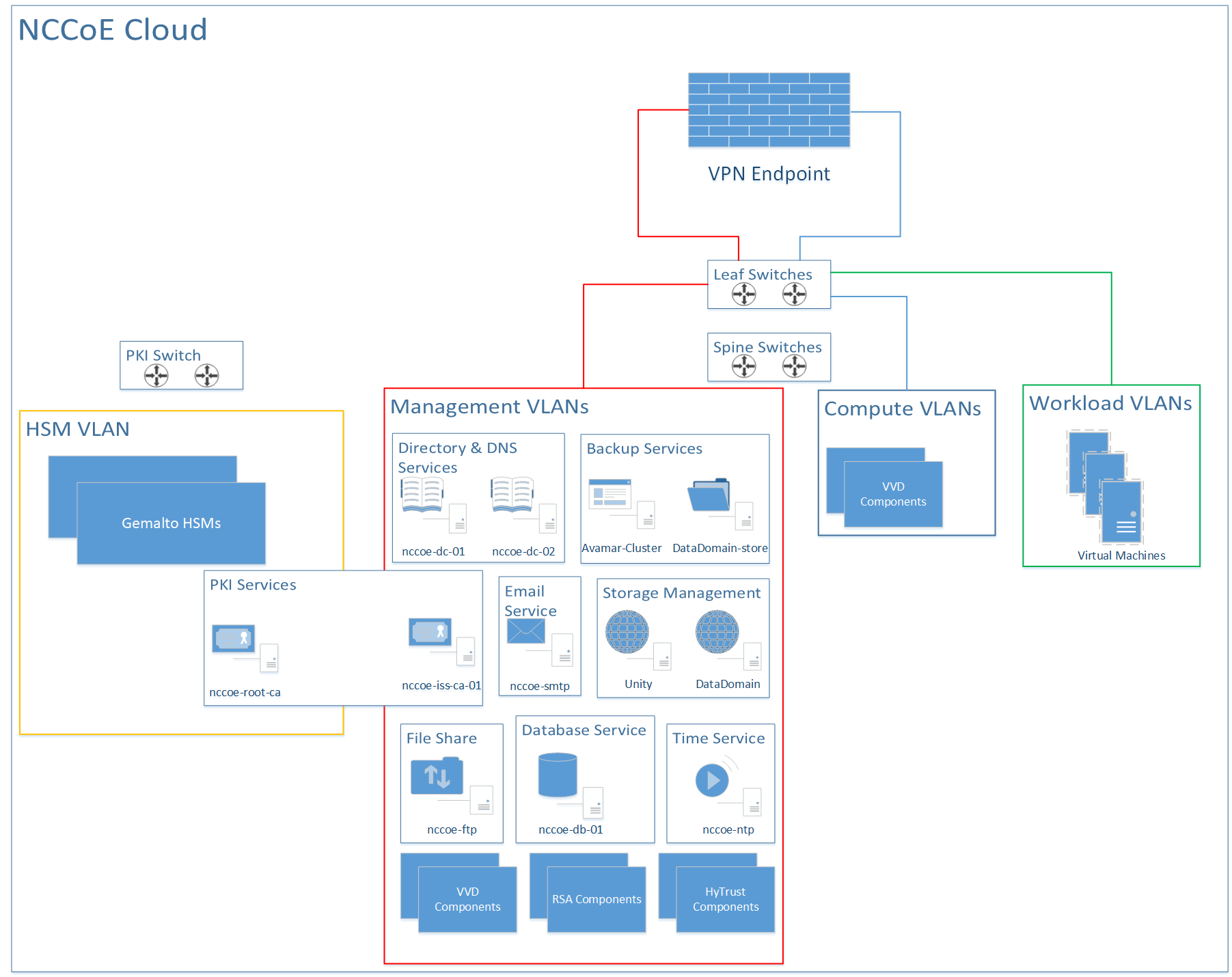
4.3 NCCoE Cloud Solution Architecture
Figure 4-2 expands the high-level solution architecture first illustrated in Figure 4-1. The following subsections provide additional details on the following parts of this architecture:
VMware cluster architectures (Section 4.3.1)
RSA cluster architecture (Section 4.3.2)
HSM architecture (Section 4.3.3)
HyTrust architecture (Section 4.3.4)
Dell leaf and spine switch architecture (Section 4.3.5)
Figure 4‑2 High-Level NCCoE Cloud Architecture
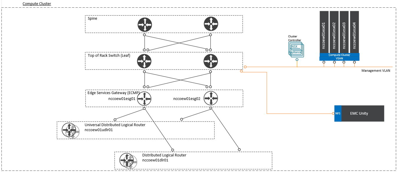
4.3.1 VMware Cluster Architectures
The diagrams of the VMware management cluster architecture (Figure 4-3) and compute cluster architecture (Figure 4-4) are based on several assumptions about the data centers in which the VVD would be implemented, including the following:
use of the leaf-spine architecture
use of Border Gateway Protocol (BGP) routing
availability of dedicated VLANs
ability to configure jumbo frames
Network File System (NFS) storage availability
use of vSAN Ready Nodes (optional)
availability of existing data-center services, such as Active Directory, DNS, SMTP, and NTP
The components described below are included in the VVD for an SDDC.
vSphere provides a powerful, flexible, and secure foundation for the SDDC. The vSphere solution includes the vCS and the PSC to provide a centralized platform for managing the virtual infrastructure. Within the VVD, PSC high availability is achieved by utilizing load balancers across multiple appliances. Additionally, dedicated vCSs are deployed to manage clusters designated for infrastructure management workloads and for compute or customer workloads. Optionally, VMware vSAN is defined within the VVD to pool together storage devices across the vSphere cluster to create a distributed shared datastore.
The VVD includes VMware NSX to virtualize the network; this solution abstracts the network from the underlying physical infrastructure. The VVD NSX solution ensures a highly available solution by utilizing both equal-cost multi-path (ECMP)-enabled and high-availability‑enabled appliances. ESGs configured to utilize the BGP routing protocol are configured as ECMP pairs and act as the north-south boundary. Routing within the logical space, east-west, is provided by high-availability-enabled distributed logical routers. In this solution, VXLAN overlays the existing Layer 3 network infrastructure, addressing scalability problems associated with cloud computing environments.
vRLI provides deep operational visibility and faster troubleshooting across physical, virtual, and cloud environments. In this solution, vRLI is designed to provide a highly available solution for each site where logs can be forwarded to a remote site for retention.
vROPS provides administrators with the ability to efficiently manage capacity and performance while also gaining visibility across the virtual infrastructure. vROPS in the VVD is designed to provide high availability while also ensuring that remote data centers are monitored. Within this design, in case of a disaster, it is possible to failover the necessary vROPS components while leaving remote collectors at their designated data centers.
vRA provides a portal where authorized individuals can request new IT services and manage cloud and IT workloads. Requests for IT services, including infrastructure, applications, desktops, and many others, are processed through a common service catalog to provide a consistent user experience despite the underlying heterogenous infrastructure. In this design, the “Large” reference architecture for vRA is followed, allowing for high availability and scalability up to 50,000 managed machines. The vRA solution includes embedded VMware Identity Manager and embedded vRO.
vRB automates cloud cost management, consumption metering, and cloud comparison, delivering cost visibility. vRB is integrated with vRA, providing cost information for the solution and pricing information per blueprint. vRB is architected to include a remote collector at each site while the vRB appliance remains in proximity to the vRA solution. vRB is protected by vSphere High Availability.
Figure 4‑3 VMware Management Cluster Architecture
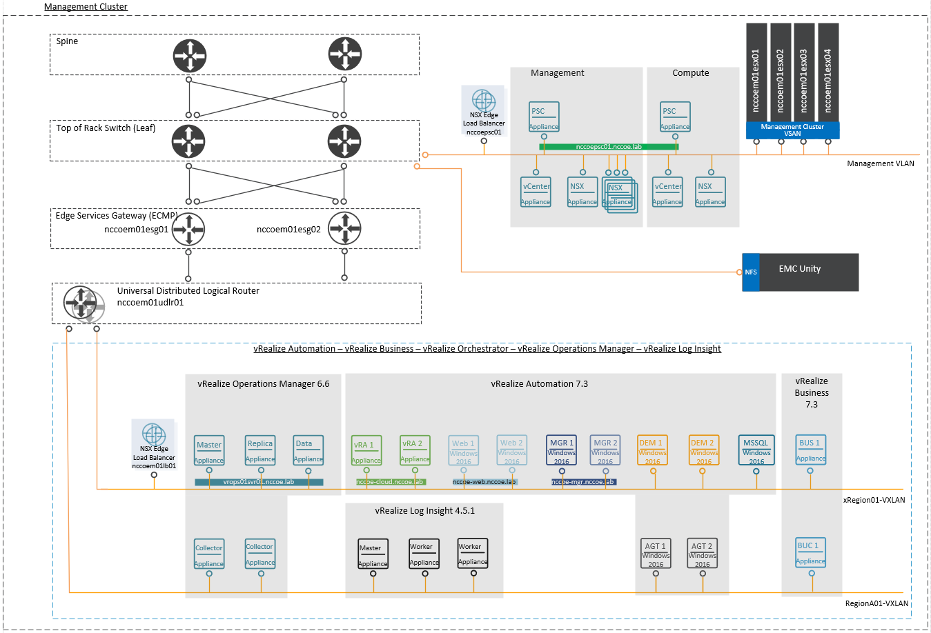
Figure 4‑4 VMware Compute Cluster Architecture
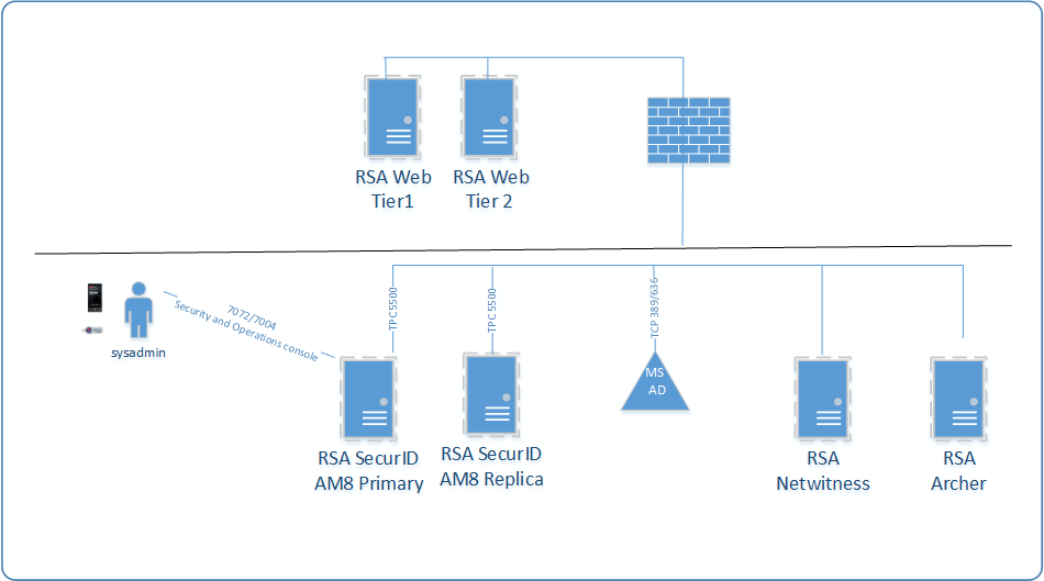
4.3.2 RSA Cluster Architecture
Figure 4-5 depicts the architecture of the RSA cluster. Within this cluster, the RSA SecurID Suite provides strong authentication for administrator access to critical trusted cloud infrastructure components. RSA NetWitness collects, analyzes, reports on, and stores log data from a variety of sources to support security policy and regulatory compliance requirements across the trusted cloud deployment. Finally, the RSA Archer risk management solution instantiates compliance with applicable requirements, such as FISMA, PCI DSS, and HIPAA, as well as industry-neutral voluntary frameworks like the NIST Cybersecurity Framework, for this trusted cloud deployment.
Figure 4‑5 RSA Cluster
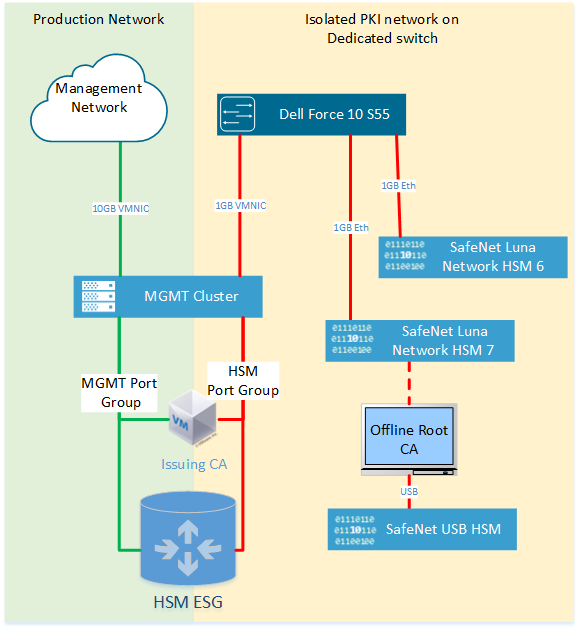
4.3.3 HSM Architecture
Figure 4-6 shows the HSM architecture in the NCCoE cloud. The following components are of the greatest interest:
The SafeNet USB HSM is a small form-factor physical device connected via USB to the Microsoft Root CA Server. To sign and issue a new Issuing CA certificate, the SafeNet USB HSM must be connected directly to the Root CA. Because the SafeNet USB HSM is primarily used to protect the Root CA’s keys, it is typically stored securely in a vault. The SafeNet USB HSM is backed up (i.e., cloned) to a secondary SafeNet USB HSM for redundancy.
SafeNet Luna Network HSM 7 is a network-attached HSM that is tightly integrated with the Microsoft Issuing CA that is located on a VM in the management cluster as a root of trust for FIPS 140-2 Level 3 Compliance.
SafeNet Luna Network HSM 6 is a network-attached HSM integrated with HTKC as a root of trust for FIPS 140-2 Level 3 Compliance.
Figure 4‑6 HSM Architecture in the NCCoE Cloud
4.3.4 HyTrust Architecture
The NCCoE trusted cloud includes several HyTrust security components, including encryption and key management, data discovery and classification, and advanced security for vSphere. From a placement standpoint, the locations of the HyTrust appliances are shown in Figure 4-7.
Figure 4‑7 HyTrust Architecture in the NCCoE Cloud
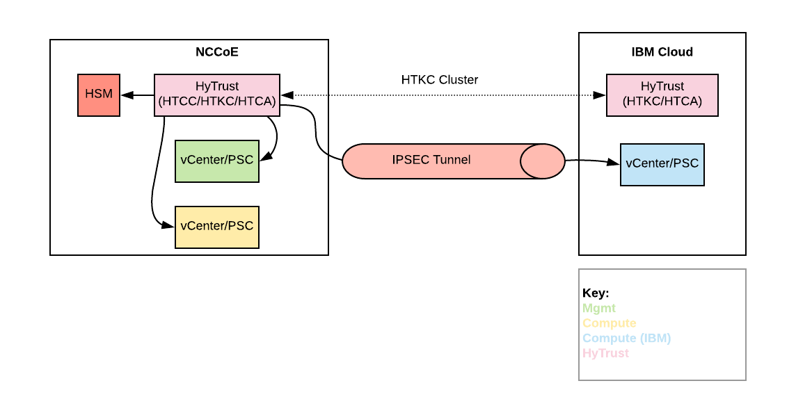
The following items explain where each type of HyTrust appliance is located within the architecture and what functions it is providing:
HTCC provides advanced security features to vSphere. Additionally, HTCC Compliance is used to verify the compliance of ESXi hosts. Users access vSphere via the “Published IP [Internet Protocol]” (PIP) via the HTCC transparent proxy. Approved actions are passed through to vSphere via a service account. Finally, HTCC conducts trust attestation for Intel TXT/TPM to provide hardware verification for HTBC. HTCC will be placed in the NCCoE management cluster. HTCC will be configured with two virtual appliances in an active/passive cluster. That HTCC cluster will service all three vSphere implementations.
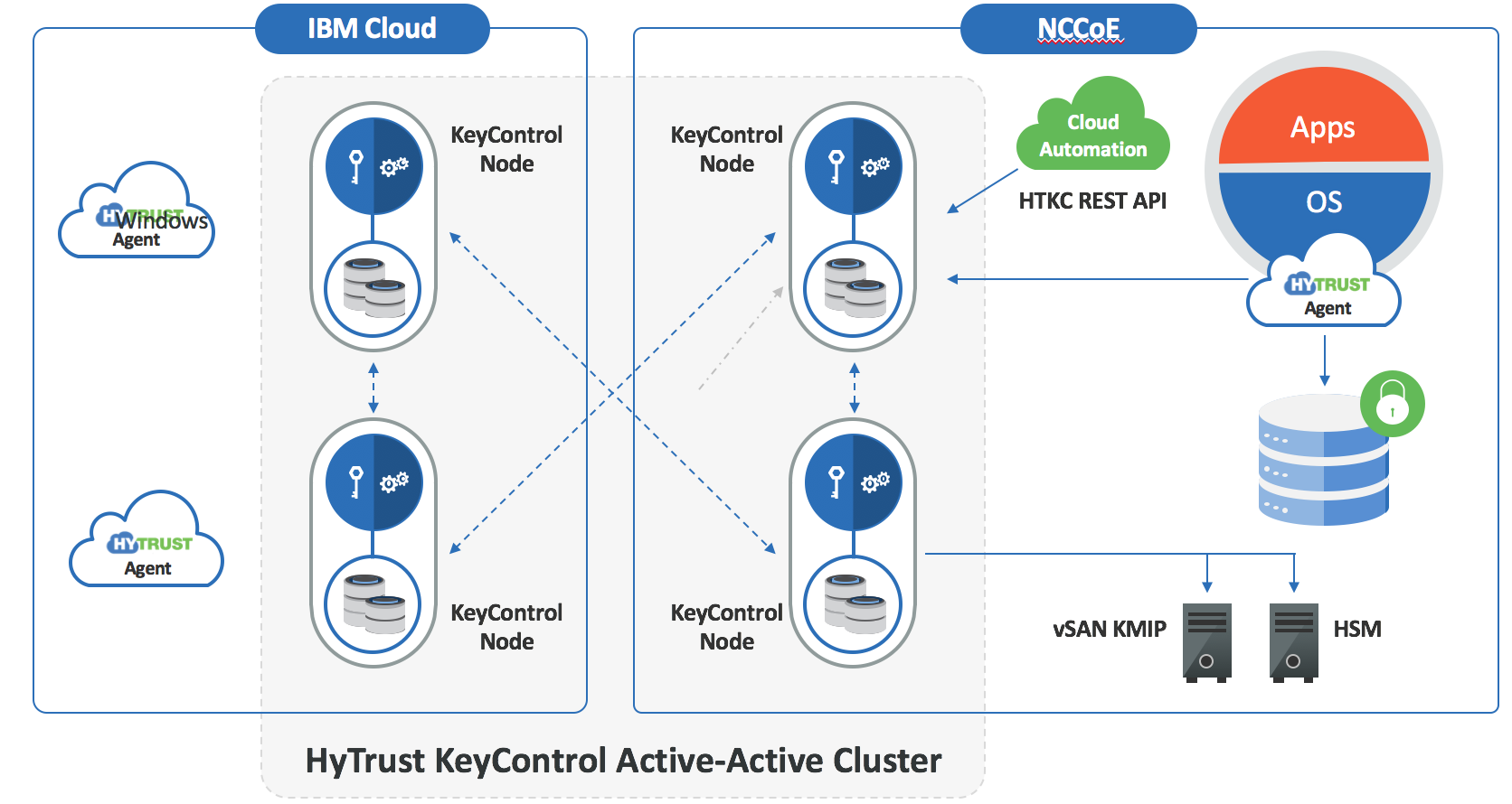
HTKC provides key management to both HTDC in-guest encryption agents and vSANs for storage‑level encryption. HTKC leverages the NCCoE SafeNet Luna HSM for hardware administration key storage. HTKC is configured as a trusted key management service in vCenter to provide key management to vSAN. Two HTKC nodes will be placed in the NCCoE management cluster, and two HTKC nodes will be placed in the IBM Cloud, with all four nodes in the same fully active cluster. Figure 4-8 depicts this cluster.
HTCA will be placed in the NCCoE management cluster and the IBM Cloud. There will be one HTCA node per location, and the nodes will not be clustered.
Figure 4‑8 HTKC Node Deployments
4.3.5 Dell Leaf and Spine Switch Architecture
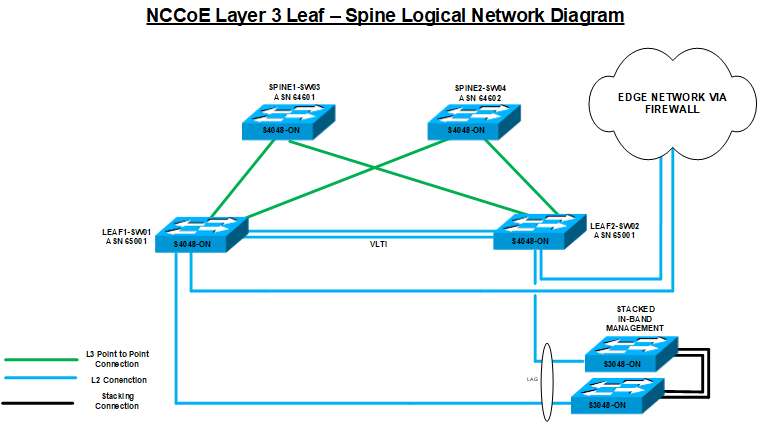
The core physical networking required for the components within the NCCoE cloud is comprised of four Dell S4048-ON switches and two Dell S3048-ON switches, as shown in Figure 4-9. The Dell S4048-ON switches are configured in a typical leaf-spine topology, with 40-gigabit (GB) interfaces for the interconnections between the switches. The spine switches are in place to handle any east-west traffic that may happen with the data center, while the leaf switches are in place to handle traffic for adjacent servers, as well as northbound traffic out of the NCCoE Cloud.
All of the Dell PowerEdge R740xd servers that comprise the ESXi servers have redundant 10 GB links connected to each of the leaf servers for direct communication with each other. The leaf switches have a Virtual Link Tunnel interconnect (VLTi) between them to provide Layer 2 aggregation between the two switches. The BGP is also enabled on the leaf switches so that they can share routes with the spine switches, and also allow the VMware NSX components to pair with them so that the leaf switches can receive routing information from NSX. The two Dell S3048-ON switches are stacked together by 10 GB interfaces so that they appear as one logical unit. The Dell S3048-ON switches also each use a 10 GB Link Aggregate (LAG) connection as an uplink to the leaf switches. The uplink from the two Dell S3048-ON switches to the leaf switches is necessary because the two Dell S3048-ON switches are mainly 1 GB Ethernet ports supporting components in the environment that have only 1 GB Ethernet connections and that need to communicate with devices that use 10 GB Enhanced Small Form-Factor Pluggable (SFP+) connections.
Figure 4‑9 NCCoE Layer 3 Leaf – Spine Logical Network Diagram
4.4 IBM Cloud Solution Architecture
ICSV is deployed on the IBM Cloud infrastructure according to a VMware, HyTrust, IBM, and Intel-validated design reference architecture. The architecture depicted in Figure 4-10 is hosted on a minimum of four bare-metal servers with Intel TXT enabled. VMware vCS is used for hypervisors with VMware vSphere stack as a service. The VMware environment is built on top of bare-metal servers and vSAN storage, and it includes the automatic deployment and configuration of an easy-to-manage logical edge firewall that is powered by VMware NSX. This provides full native access to the entire VMware stack, including the vSphere 6.5 Enterprise Plus edition; the NSX for Service Providers edition; and the centralized platform for management, vCS. The solution, coupled with Windows Active Directory, HTCC, and HTDC, provides a solid foundation to address security and compliance concerns. The entire environment can be provisioned in a matter of hours, and the elastic bare-metal infrastructure can rapidly scale out its compute capacity when needed.
See Section 4.3 for more information on the architecture of the solution components from VMware, HyTrust, and others. Because some of the same components are used for both clouds to extend the management plane across the infrastructure, details of those components are omitted from this section to avoid duplication.
Figure 4‑10 IBM Cloud Architecture
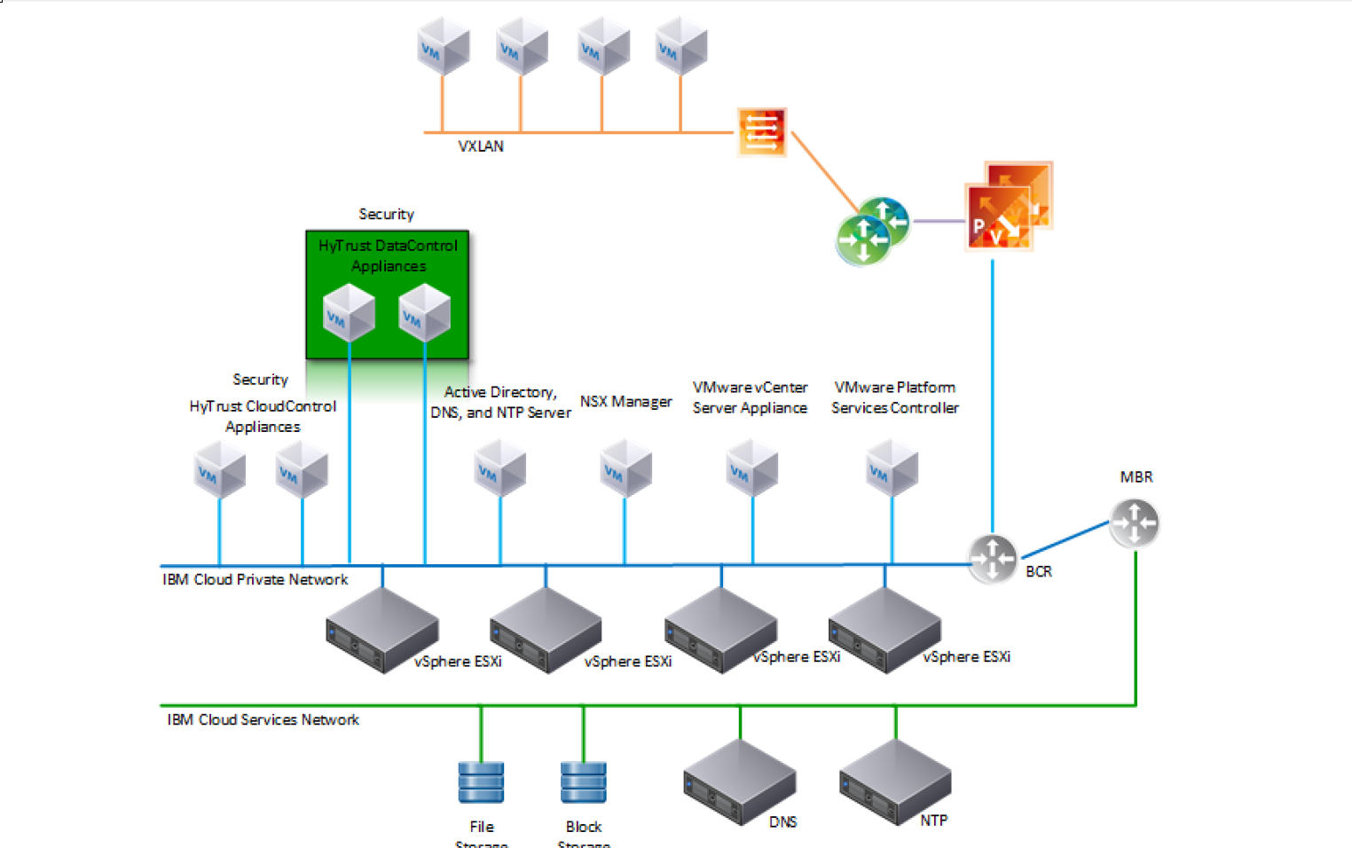
5 Security Characteristics Analysis
The purpose of the security characteristics analysis is to understand the extent to which the project meets its objective of demonstrating a trusted cloud implementation leveraging commercial off-the-shelf technology. In addition, it seeks to understand the security benefits and drawbacks of the example solution.
5.1 Assumptions and Limitations
The security characteristics analysis has the following limitations:
It is neither a comprehensive test of all security components nor a red-team exercise.
It cannot identify all weaknesses.
It does not include the lab infrastructure. It is assumed that devices are hardened. Testing these devices would reveal only weaknesses in implementation that would not be relevant to those adopting this reference architecture.
5.2 Demonstration of the Capabilities
The analysis is based on defining a set of use case scenarios for the example solution, and then demonstrating the security capabilities that can be achieved with the example solution for each use case scenario. Each demonstration was documented, including the basic steps performed and the security capabilities achieved.
5.2.1 Use Case Scenario 1: Demonstrate Control and Visibility for the Trusted Hybrid Cloud Environment
The business problem is needing to have a well-secured cloud environment to reduce the risk of a compromise of that environment.
Assumptions for the trusted hybrid cloud environment (steps taken before the demonstrations occur) are as follows:
The cryptographic, compute, storage, and network hardware components are secured and hardened.
The VVD and the IBM Cloud for VMware – vCS have been instantiated on IBM Cloud stacks through automation scripts.
The cryptographic network is separated and isolated from the management cluster and the tenant workloads cluster.
The user accounts are isolated and secured based on defined functional roles following the principle of least privilege.
The core components of the VVD and vCS, third-party software components, and all core services are secured and hardened using recommended practices, such as vendor-developed or community-developed secure configuration guides or DISA STIGs.
RSA NetWitness Logs is installed on the virtual machine or dedicated hardware.
RSA Archer Suite and the Public Sector Use Cases (Assessment & Authorization [A&A], Continuous Monitoring) are installed.
Logs from core services are being forwarded to RSA NetWitness Logs.
One or more industry-standard cloud service provider certifications, such as ISO, PCI, Cloud Security Alliance (CSA), Service Organization Control (SOC), HIPAA, and FedRAMP, are leveraged.
Capability demonstrations:
Show the configuration of the hardware components, including the HSM, the compute node, the storage device, and the network switches.
Show the VVD and vCS stacks in vCenter (e.g., vSAN is encrypted).
Show the backup solution for the resiliency and recovery of workloads in a disaster‑recovery scenario.
Show the three isolation domains, including the cryptographic, management, and tenant workloads in NSX.
Show multifactor authentication with an RSA SecurID token and the Active Directory domain groups and access rights structure.
Scan and show the secure configuration of VMware software components, such as ESXi, NSX, and Windows domain controller, by using CloudControl and a Windows configuration scanner. Figure 5-1 shows an example of results from a secure configuration scan.
Figure 5‑1 Example of Secure Configuration Scan Results
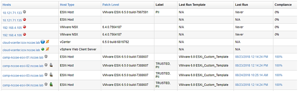
Scan and show any software vulnerabilities of an ESXi node and a Microsoft workload.
Show the IBM FedRAMP report.
Show the configuration of the log collector for ingesting and enriching VMware ESXi logs.
Show the logs and alerts (if any) in the Analyst UI.
Show the ability to raise an Incident from RSA NetWitness Logs to RSA Archer Suite.
Show the configuration of the Archer Public Sector Use Cases to accept and/or ingest information from various components about risks in the trusted hybrid cloud environment.
Show the analyst interface and outputs of Archer Public Sector Use Cases in recording compliance and enabling risk mitigation activities.
The potential benefits of this are reducing the risk that workloads running in that cloud environment are compromised, and identifying potential security issues more quickly.
5.2.2 Use Case Scenario 2: Demonstrate Control of Workloads and Data Security
The business problem is needing to protect workloads so they only execute on authorized compute nodes.
Assumptions for the trusted hybrid cloud environment (steps taken before the demonstrations occur) are as follows:
Workloads are encrypted and are running on a trusted compute node with a specific asset tag (PCI or HIPAA) within a mixed cluster.
Secondary approval is enforced for highly sensitive systems and/or operations.
Capability demonstrations:
Show that the workload on the trusted compute node is decrypted, as it matches the trust and asset tag policy. Figure 5-2 shows examples of nodes with their labels (e.g., TRUSTED, PII). Figure 5-3 shows verification that a workload on one of the nodes has been decrypted.
Figure 5‑2 Examples of Trusted Compute Nodes
Figure 5‑3 Example of Decrypted Workload
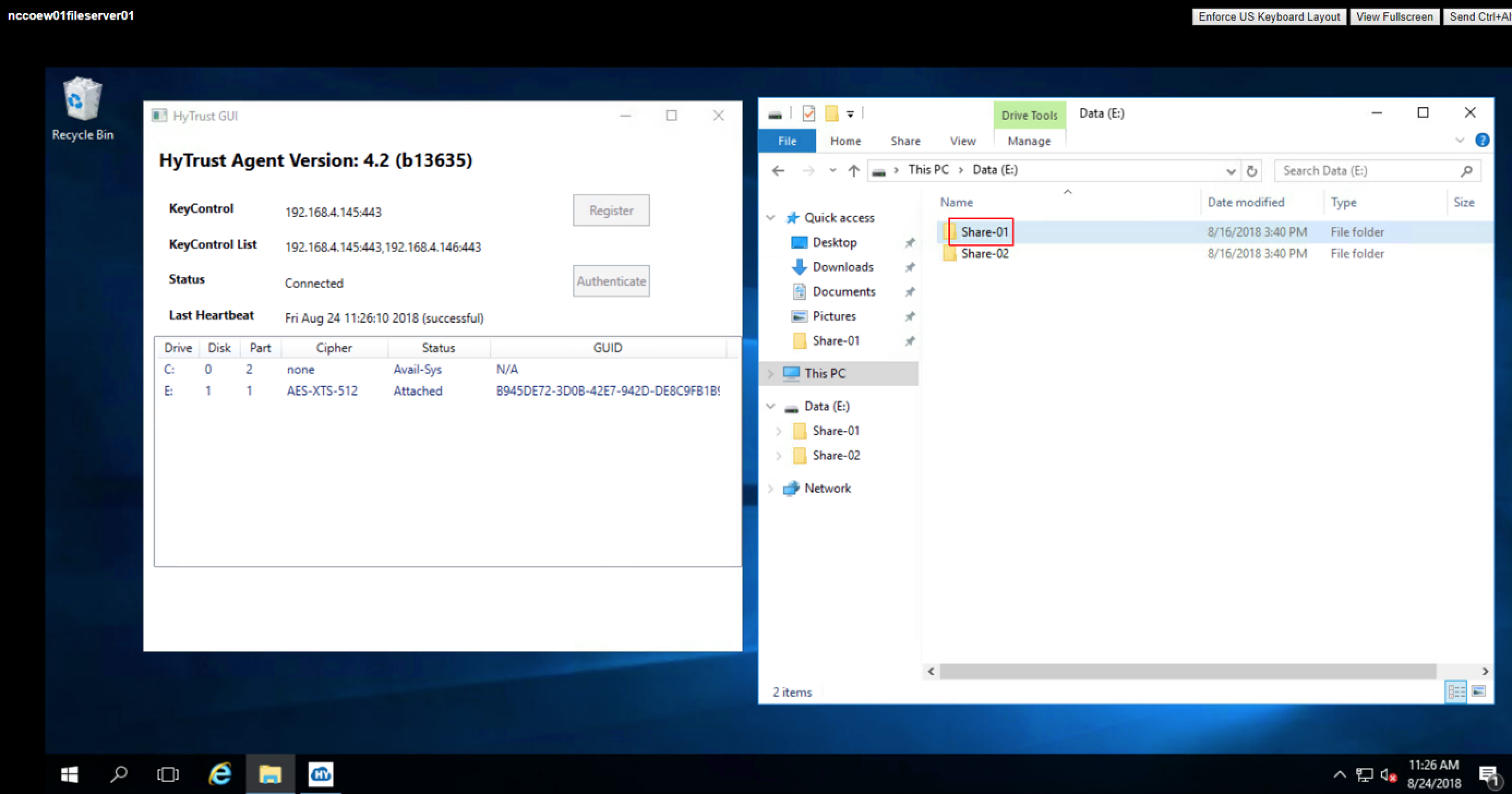
Migrate the workload to a compute node without the same asset tag policy, and show that the workload cannot be decrypted on the untrusted compute node. Figure 5-4 presents an example of a workload running on a server that does not have any tags. Figure 5-5 shows that the same workload cannot be decrypted because the server on which it runs lacks the necessary tags.
Figure 5‑4 Example of Workload on Untagged Server
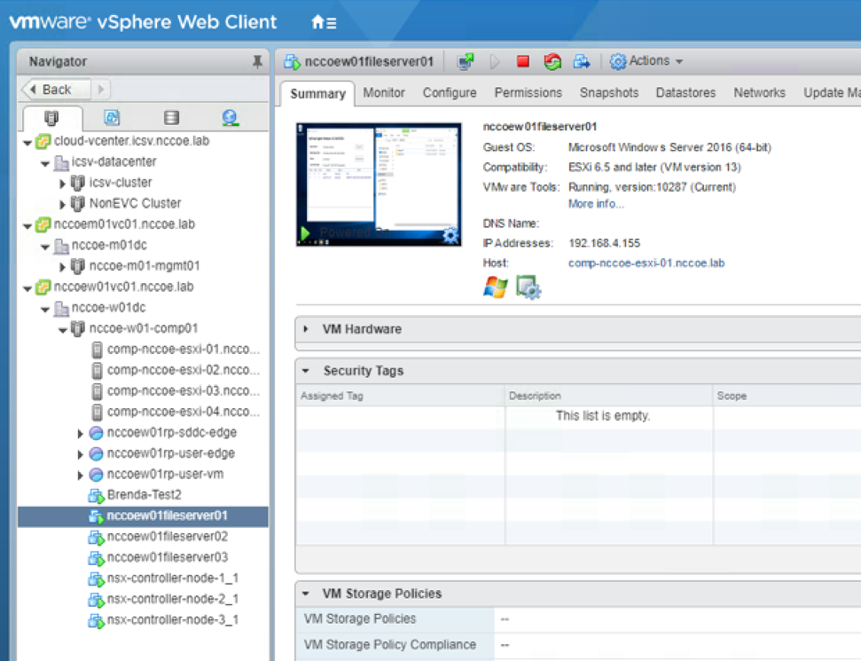
Figure 5‑5 Example of Workload that Cannot Be Decrypted
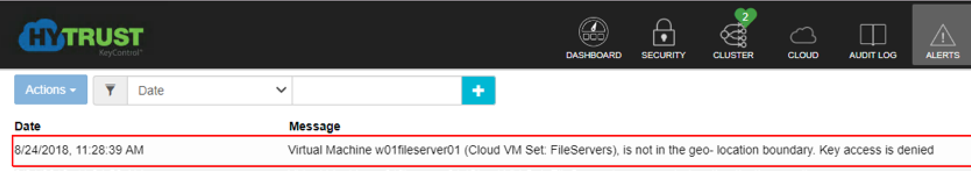
Migrate the workload back to a trusted compute node, and show that the workload can be decrypted and that the data can be accessed on the trusted compute node. Figure 5-6 shows that the workload has been migrated to a trusted and tagged server. Figure 5-7 shows that the workload can decrypt its data again because it is running on a trusted and tagged server.
Figure 5‑6 Example of Workload Migrated to Trusted and Tagged Server
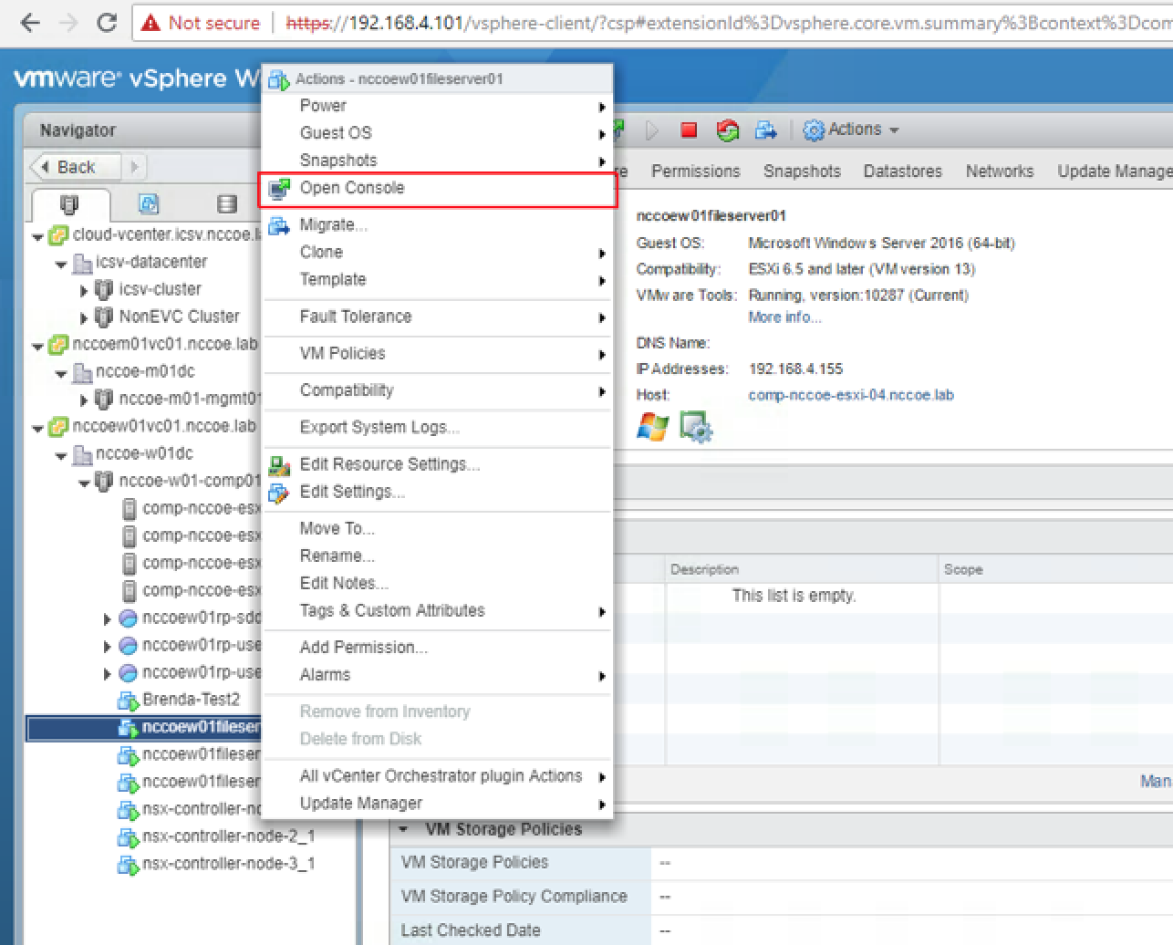
Figure 5‑7 Example of Workload Running on Trusted and Tagged Server
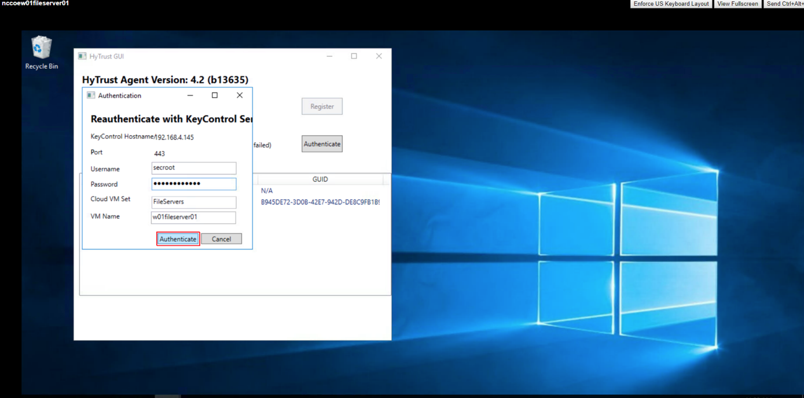
Show that two individuals are required to authorize the deletion of a high-value asset.
Scan and classify data based on a data classification schema, such as personally identifiable information.
The potential benefit of this is reducing the risk that workloads are compromised.
5.2.3 Use Case Scenario 3: Demonstrate a Workload Security Policy in a Hybrid Cloud
There are two business problems addressed. The first is needing to move workloads (VMs and data) from one trusted compute node to a second one without any degradation of security posture or any loss of information in order to perform scheduled maintenance on the first trusted compute node. An example of a reason for scheduled maintenance is to patch or upgrade the hypervisor. The second is ensuring scripts, configurations, and other files or settings with hard-coded IP addresses or domain names continue to work even when workloads containing them are migrated from one cloud to another.
Assumptions for the trusted hybrid cloud environment (steps taken before the demonstrations occur) are as follows:
The trusted on-premises environment has been instantiated.
A secure connection has been established between the on-premises environment and the public cloud instance.
The security capabilities from the on-premises environment have been extended to the public cloud instance by integrating it into the on-premises management plane.
A three-tier web application is running in the on-premises environment with a specified security policy (e.g., data protection, network segmentation, compliance requirements).
Capability demonstrations:
Show that the three-tier web application’s security policy is enforced within the on-premises environment.
Show that the three-tier web application can be migrated from the on-premises environment to the public cloud instance.
Show that the workload continues to operate normally after migration and its security posture is not negatively impacted by running the scripts with hard-coded IP addresses and domain names.
Show that the three-tier web application’s security policy is persistent after the migration to the public cloud instance.
The potential benefits of this are reducing the risk that workloads are compromised and reducing the risk that operations are interrupted because of a workload migration.
5.2.4 Use Case Scenario 4: Demonstrate Recovery From an Unexpected Infrastructure Outage
The business problem is needing to quickly restore operations for a three-tier application when an unexpected infrastructure outage occurs at the site where the application is hosted, while also ensuring there is no degradation of security posture for the application when it is restored at another site. This allows the application to continue functioning while the outage at the first site is addressed.
Assumptions for the trusted hybrid cloud environment (steps taken before the demonstrations occur) are as follows:
When the outage started, the workloads were encrypted and were running on a trusted compute node with a specific asset tag (PCI or HIPAA) within a mixed cluster.
The outage has made all three tiers of the application unavailable at the original site, and on-premises recovery is not possible until the outage has been resolved.
A second trusted compute node within a different data center acting as a disaster recovery site is authorized to run the same types of workloads as the first trusted compute node.
Secondary approval is enforced for highly sensitive systems and/or operations.
Capability demonstrations:
Show that the three tiers of the application are present at the disaster recovery site and that each tier is up to date.
Show that Fault Tolerance (FT) was regularly backing up data from the original site to the disaster recovery site until shortly before the outage occurred.
Show that the workloads on the trusted compute node at the disaster recovery site can be decrypted, as they match the trust and asset tag policy.
Show that the NSX Universal Distributed Firewall rules are present and enforced at the receiving end (the disaster recovery site) to enable updating the workloads and data on the trusted compute node.
The potential benefit of this is to minimize disruption from unscheduled outages, which means operations should be restored more quickly.
Note that this demonstration is simple, with static content. The intent is that this demonstration could be extended to a more complex scenario, such as applications with dynamic content where the application developers need to decide how the application should handle failures, including possibly retaining state when a failure occurs and maintaining persistent connections.
5.2.5 Use Case Scenario 5: Demonstrate Providing Visibility into Network Traffic Patterns
The business problem is needing to have visibility into network traffic flow patterns so abnormal patterns can be identified and investigated.
Assumptions for the trusted hybrid cloud environment (steps taken before the demonstrations occur) are as follows:
Logging has been enabled at ESXi Hosts, NSX Managers, NSX Controllers, Edge Service Gateways, Control VMs, and DFWs, including tunnels.
NetWitness is ready and available to collect and store logs from other hosts.
Capability demonstrations:
Show that authorized administrators can see a vRLI custom dashboard for traffic flows indicating what is talking to what, both physical and virtual.
Show that the traffic flows include source, destination, ports, and protocol.
Show that the traffic flows from all the devices logging the flows are transferred to NetWitness.
The potential benefit of this is to identify suspicious activity, such as large data bursts, that may indicate exfiltration of sensitive data or other security problems.
5.2.6 Use Case Scenario 6: Demonstrate Application Zero Trust
The business problem is preventing unauthorized communications with a particular application.
Assumptions for the trusted hybrid cloud environment (steps taken before the demonstrations occur) are as follows:
An application is executing within a workload running on a trusted compute node.
The infrastructure supporting the application has been allowlisted through DFW.
Capability demonstrations:
Show that communications from the allowlisted infrastructure components are permitted.
Show that communications from anywhere other than the allowlisted infrastructure components are denied and such communications flagged or alerted on.
The potential benefit of this is to prevent attackers and other unauthorized parties from accessing the application and using it or compromising it.