NIST SPECIAL PUBLICATION 1800-13C
Mobile Application Single Sign-On:
Improving Authentication for Public Safety First Responders
Volume C:
How-to Guides
William Fisher
Paul Grassi*
Applied Cybersecurity Division
Information Technology Laboratory
Spike E. Dog
Santos Jha
William Kim
Taylor McCorkill*
Joseph Portner*
Mark Russell*
Sudhi Umarji
The MITRE Corporation
McLean, Virginia
William C. Barker
Dakota Consulting
Silver Spring, Maryland
*Former employee; all work for this publication was done while at employer.
August 2021
FINAL
The first and second drafts of this publication are available free of charge from
https://www.nccoe.nist.gov/library/mobile-application-single-sign-nist-sp-1800-13-practice-guide
DISCLAIMER
Certain commercial entities, equipment, products, or materials may be identified by name or company logo or other insignia in order to acknowledge their participation in this collaboration or to describe an experimental procedure or concept adequately. Such identification is not intended to imply special status or relationship with NIST or recommendation or endorsement by NIST or NCCoE; neither is it intended to imply that the entities, equipment, products, or materials are necessarily the best available for the purpose.
While NIST and the NCCoE address goals of improving management of cybersecurity and privacy risk through outreach and application of standards and best practices, it is the stakeholder’s responsibility to fully perform a risk assessment to include the current threat, vulnerabilities, likelihood of a compromise, and the impact should the threat be realized before adopting cybersecurity measures such as this recommendation.
National Institute of Standards and Technology Special Publication 1800-13C, Natl. Inst. Stand. Technol. Spec. Publ. 1800-13C, 159 pages (August 2021), CODEN: NSPUE2
FEEDBACK
As a private-public partnership, we are always seeking feedback on our practice guides. We are particularly interested in seeing how businesses apply NCCoE reference designs in the real world. If you have implemented the reference design, or have questions about applying it in your environment, please email us at psfr-nccoe@nist.gov.
All comments are subject to release under the Freedom of Information Act.
NATIONAL CYBERSECURITY CENTER OF EXCELLENCE
The National Cybersecurity Center of Excellence (NCCoE), a part of the National Institute of Standards and Technology (NIST), is a collaborative hub where industry organizations, government agencies, and academic institutions work together to address businesses’ most pressing cybersecurity issues. This public-private partnership enables the creation of practical cybersecurity solutions for specific industries, as well as for broad, cross-sector technology challenges. Through consortia under Cooperative Research and Development Agreements (CRADAs), including technology partners—from Fortune 50 market leaders to smaller companies specializing in information technology security—the NCCoE applies standards and best practices to develop modular, adaptable example cybersecurity solutions using commercially available technology. The NCCoE documents these example solutions in the NIST Special Publication 1800 series, which maps capabilities to the NIST Cybersecurity Framework and details the steps needed for another entity to re-create the example solution. The NCCoE was established in 2012 by NIST in partnership with the State of Maryland and Montgomery County, Maryland.
NIST CYBERSECURITY PRACTICE GUIDES
NIST Cybersecurity Practice Guides (Special Publication 1800 series) target specific cybersecurity challenges in the public and private sectors. They are practical, user-friendly guides that facilitate the adoption of standards-based approaches to cybersecurity. They show members of the information security community how to implement example solutions that help them align with relevant standards and best practices and provide users with the materials lists, configuration files, and other information they need to implement a similar approach.
The documents in this series describe example implementations of cybersecurity practices that businesses and other organizations may voluntarily adopt. These documents do not describe regulations or mandatory practices, nor do they carry statutory authority.
ABSTRACT
On-demand access to public safety data is critical to ensuring that public safety and first responder (PSFR) personnel can deliver the proper care and support during an emergency. This necessitates heavy reliance on mobile platforms while in the field, which may be used to access sensitive information. However, complex authentication requirements can hinder the process of providing emergency services, and any delay—even seconds—can become a matter of life or death. In collaboration with NIST’s Public Safety Communications Research (PSCR) Division and industry stakeholders, the NCCoE aims to help PSFR personnel efficiently and securely gain access to mission data via mobile devices and applications.
This practice guide describes a reference design for multifactor authentication (MFA) and mobile single sign-on (MSSO) for native and web applications, while improving interoperability among mobile platforms, applications, and identity providers, regardless of the application development platform used in their construction. This guide discusses major architecture design considerations, explains security characteristics achieved by the reference design, and maps the security characteristics to applicable standards and security control families. For parties interested in adopting all or part of the reference architecture, this guide includes a detailed description of the installation, configuration, and integration of all components.
KEYWORDS
access control; authentication; authorization; identity; identity management; identity provider; relying party; single sign-on
ACKNOWLEDGMENTS
We are grateful to the following individuals for their generous contributions of expertise and time.
Name |
Organization |
|---|---|
Donna Dodson* |
NIST NCCoE |
Tim McBride |
NIST NCCoE |
Jeff Vettraino |
FirstNet |
FNU Rajan |
FirstNet |
John Beltz |
NIST Public Safety Communications Research Lab |
Chris Leggett |
Ping Identity |
Paul Madsen |
Ping Identity |
John Bradley |
Yubico |
Adam Migus |
Yubico |
Derek Hanson |
Yubico |
Adam Lewis |
Motorola Solutions |
Mike Korus |
Motorola Solutions |
Dan Griesmann |
Motorola Solutions |
Arshad Noor |
StrongKey |
Pushkar Marathe |
StrongKey |
Max Smyth |
StrongKey |
Scott Wong |
StrongKey |
Akhilesh Sah |
Nok Nok Labs |
Avinash Umap |
Nok Nok Labs |
*Former employee; all work for this publication was done while at employer.
The Technology Partners/Collaborators who participated in this build submitted their capabilities in response to a notice in the Federal Register. Respondents with relevant capabilities or product components were invited to sign a Cooperative Research and Development Agreement (CRADA) with NIST, allowing them to participate in a consortium to build this example solution. We worked with:
Technology Partner/Collaborator |
Build Involvement |
|---|---|
Federation Server |
|
Mobile Applications |
|
External Authenticators |
|
Fast Identity Online (FIDO) Universal Authentication Framework (UAF) Server |
|
FIDO Universal Second Factor (U2F) Server |
PATENT DISCLOSURE NOTICE
NOTICE: The Information Technology Laboratory (ITL) has requested that holders of patent claims whose use may be required for compliance with the guidance or requirements of this publication disclose such patent claims to ITL. However, holders of patents are not obligated to respond to ITL calls for patents and ITL has not undertaken a patent search in order to identify which, if any, patents may apply to this publication.
As of the date of publication and following call(s) for the identification of patent claims whose use may be required for compliance with the guidance or requirements of this publication, no such patent claims have been identified to ITL.
No representation is made or implied by ITL that licenses are not required to avoid patent infringement in the use of this publication.
List of Figures
Figure 1‑1 Lab Build Architecture
Figure 2‑1 Comparison of UAF and U2F Standards
Figure 2‑2 SFAuthenticationSession Consent Prompt
Figure 2‑3 Safari Transition Prompt
Figure 2‑4 FIDO UAF Architectural Overview
Figure 2‑6 PSX Cockpit Setup, Continued
Figure 2‑7 PSX Cockpit Group List Selection
Figure 2‑9 PSX Cockpit Group List Setup Complete
Figure 2‑10 PSX Cockpit User Interface
Figure 2‑11 PSX Mapping User Interface
Figure 2‑12 PSX Mapping Group Member Information
Figure 2‑13 PSX Messenger User Interface
Figure 2‑14 PSX Messenger Messages
Figure 2‑15 FIDO U2F Registration
Figure 2‑16 FIDO U2F Authentication
Figure 2‑17 Nok Nok Labs Tutorial Application Authentication
Figure 2‑18 Nok Nok Labs Tutorial Application Login
Figure 2‑19 FIDO UAF Registration Interface
Figure 2‑20 FIDO UAF Registration QR Code
Figure 2‑21 FIDO UAF Registration Device Flow, Android Device
Figure 2‑22 FIDO UAF Registration Device Flow, iPhone X
Figure 2‑23 FIDO UAF Fingerprint Authenticator, Android Device
Figure 2‑24 FIDO UAF Registration Success
Figure 2‑25 Linked Frameworks and Libraries
Figure 2‑26 Creating a New Run Script Phase
Figure 2‑27 Carthage Run Script
Figure 3‑1 Access Token Attribute Mapping Framework
Figure 3‑2 Server Roles for AS
Figure 3‑6 Access Token Management Instance
Figure 3‑7 Access Token Manager Instance Configuration
Figure 3‑8 Access Token Manager Attribute Contract
Figure 3‑9 OAuth Client Registration, Part 1
Figure 3‑10 OAuth Client Registration, Part 2
Figure 3‑11 Create Adapter Instance
Figure 3‑12 FIDO Adapter Settings
Figure 3‑13 FIDO Adapter Contract
Figure 3‑14 FIDO Adapter Instance Summary
Figure 3‑15 Policy Contract Information
Figure 3‑16 Policy Contract Attributes
Figure 3‑17 Create Authentication Policy Contract Mapping
Figure 3‑18 Authentication Policy Contract Fulfillment
Figure 3‑19 Create Access Token Attribute Mapping
Figure 3‑20 Access Token Mapping Contract Fulfillment
Figure 3‑21 Create IdP Connection
Figure 3‑22 IdP Connection Options
Figure 3‑23 IdP Connection General Info
Figure 3‑24 IdP Connection–User-Session Creation
Figure 3‑25 IdP Connection OAuth Attribute Mapping
Figure 3‑26 IdP Connection—Protocol Settings
Figure 3‑27 Policy Contract for SAML RP
Figure 3‑28 Contract Mapping for SAML RP
Figure 3‑29 IdP Connection Type
Figure 3‑30 IdP Connection Options
Figure 3‑31 IdP Connection General Info
Figure 3‑32 IdP Connection Authentication Policy Contract
Figure 3‑33 IdP Connection Policy Contract Mapping
Figure 3‑34 IdP Connection OAuth Attribute Mapping
Figure 3‑35 IdP Connection Protocol Settings
Figure 3‑36 IdP Connection Activation and Summary
Figure 3‑37 Authentication Selector Instance
Figure 3‑38 Authentication Selector Details
Figure 3‑39 Selector Result Values
Figure 3‑41 Authentication Policy
Figure 3‑42 Policy Contract Mapping for IdP Connections
Figure 3‑43 Policy Contract Mapping for Local Authentication
Figure 4‑1 Active Directory Users and Computers
Figure 4‑2 Server Configuration
Figure 4‑4 LDAP Data Store Configuration
Figure 4‑5 Server Roles for SAML IdP
Figure 4‑6 SAML IdP Federation Info
Figure 4‑7 Create Password Credential Validator
Figure 4‑8 Credential Validator Configuration
Figure 4‑9 Password Credential Validator Extended Contract
Figure 4‑10 Password Validator Summary
Figure 4‑11 HTML Form Adapter Instance
Figure 4‑12 Form Adapter Settings
Figure 4‑13 Form Adapter Extended Contract
Figure 4‑14 Create U2F Adapter Instance
Figure 4‑15 U2F Adapter Settings
Figure 4‑16 IdP Authentication Policy
Figure 4‑17 SP Connection Type
Figure 4‑18 SP Connection General Info
Figure 4‑19 SP Browser SSO Profiles
Figure 4‑20 Assertion Identity Mapping
Figure 4‑21 Assertion Attribute Contract
Figure 4‑22 Assertion Attribute Contract Fulfillment
Figure 4‑23 Browser SSO Protocol Settings
Figure 4‑25 Create Access Token Manager
Figure 4‑26 Access Token Manager Configuration
Figure 4‑27 Access Token Attribute Contract
Figure 4‑28 Access Token Contract Fulfillment
Figure 4‑29 Data Store for User Lookup
Figure 4‑30 Attribute Directory Search
Figure 4‑31 Access Token Contract Fulfillment
Figure 4‑32 Access Token Issuance Criteria
Figure 4‑33 OIDC Policy Creation
Figure 4‑34 OIDC Policy Attribute Contract
Figure 4‑35 OIDC Policy Contract Fulfillment
Figure 4‑36 OIDC Client Configuration
Figure 6‑1 Glassfish SSL Settings
Figure 7‑1 Using Postman to Obtain the ID Token
Figure 7‑2 Authorization Prompt
Figure 7‑3 Token Introspection Request and Response
1 Introduction
The following guide demonstrates a standards-based example solution for efficiently and securely gaining access to mission-critical data via mobile devices and applications. This guide demonstrates multifactor authentication (MFA) and mobile single sign-on (MSSO) solutions for native and web applications using standards-based commercially available and open‑source products. We cover all of the products that we employed in our solution set. We do not re-create the product manufacturer’s documentation. Instead, we provide pointers to where this documentation is available from the manufacturers. This guide shows how we incorporated the products together in our environment as a reference implementation of the proposed build architecture for doing MSSO.
Since May 2018, when this project build was initially completed at the NCCoE laboratory, some of the products used in the build have migrated to new platforms. In addition, new specifications and standards used by the products have been published and revised. While the general integration concepts demonstrated in this guide still apply, implementers using newer or different products will have to tailor their implementation to meet the specific requirements of those products and specifications. Thus, the implementation details will be different.
Note: This is not a comprehensive tutorial. There are many possible service and security configurations for these products that are out of scope for this reference solution set.
1.1 Practice Guide Structure
This National Institute of Standards and Technology (NIST) Cybersecurity Practice Guide demonstrates a standards-based example solution and provides users with the information they need to replicate this approach to implementing our MSSO build. The example solution is modular and can be deployed in whole or in part.
This guide contains three volumes:
NIST Special Publication (SP) 1800-13A: Executive Summary
NIST SP 1800-13B: Approach, Architecture, and Security Characteristics—what we built and why
NIST SP 1800-13C: How-To Guides—instructions for building the example solution (you are here)
See Section 2 in Volume B of this guide for a more detailed overview of the different volumes and sections, and the audiences that may be interested in each.
1.2 Build Overview
The National Cybersecurity Center of Excellence (NCCoE) worked with its build team partners to create a lab demonstration environment that includes all of the architectural components and functionality described in Section 4 of Volume B of this build guide. This includes mobile devices with sample applications, hardware and software-based authenticators to demonstrate the Fast Identity Online (FIDO) standards for MFA, and the authentication server and authorization server (AS) components required to demonstrate the AppAuth authorization flows (detailed in Internet Engineering Task Force [IETF] Request for Comments [RFC] 8252 [C1] ) with federated authentication to a Security Assertion Markup Language (SAML) Identity Provider (IdP) and an OpenID Connect (OIDC) provider. The complete build includes several systems deployed in the NCCoE lab by StrongKey, Yubico, and Ping Identity as well as cloud-hosted resources made available by Motorola Solutions and by Nok Nok Labs.
This section of the build guide documents the build process and specific configurations that were used in the lab.
1.2.1 Usage Scenarios
The build architecture supports three usage scenarios. The scenarios all demonstrate single sign-on (SSO) among Motorola Solutions Public Safety Experience (PSX) applications and custom-built Apple iPhone operating system (iOS) demo applications using the AppAuth pattern, but differ in the details of the authentication process. The three authentication mechanisms are as follows:
The OAuth AS directly authenticates the user with FIDO Universal Authentication Framework (UAF); user accounts are managed directly by the service provider.
The OAuth AS redirects the user to a SAML IdP, which authenticates the user with a password and FIDO Universal Second Factor (U2F).
The OAuth AS redirects the user to an OIDC IdP, which authenticates the user with FIDO UAF.
In all three scenarios, once the authentication flow is completed, the user can launch multiple mobile applications without additional authentication, demonstrating SSO. These three scenarios were chosen to reflect different real-world implementation options that public safety and first responder (PSFR) organizations might choose. Larger PSFR organizations may host (or obtain from a service provider) their own IdPs, enabling them to locally manage user accounts, group memberships, and other user attributes, and to provide them to multiple relying parties (RPs) through federation. SAML is currently the most commonly used federation protocol, but OIDC might be preferred for new implementations. As demonstrated in this build, RPs can support both protocols more or less interchangeably. For smaller organizations, a service provider might also act in the role of “identity provider of last resort,” maintaining user accounts and attributes on behalf of organizations.
1.2.2 Architectural Overview
Figure 1‑1 shows the lab build architecture.
Figure 1‑1 Lab Build Architecture
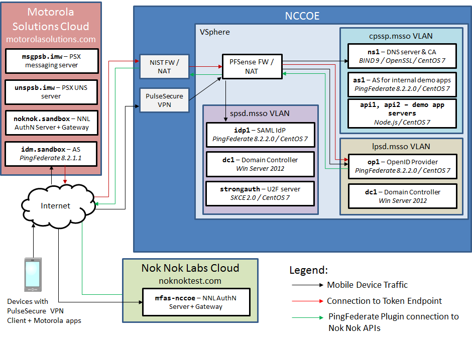
Figure 1‑1 depicts the four environments that interact in the usage scenarios:
Motorola Solutions cloud—a cloud-hosted environment providing the back-end application servers for the Motorola Solutions PSX Mapping and Messaging applications, as well as an OAuth AS that the application servers use to authorize requests from mobile devices
Nok Nok Labs cloud—a cloud-hosted server running both the Nok Nok Authentication Server (NNAS) and the Nok Nok Labs Gateway
NCCoE—the NCCoE lab, including several servers hosted in a vSphere environment running the IdPs and directory services that would correspond to PSFR organizations’ infrastructure to support federated authentication to a service provider, like Motorola Solutions. An additional AS and some demonstration application back ends are also hosted in the NCCoE lab for internal testing.
mobile devices connected to public cellular networks with the required client software to authenticate to, and access, Motorola Solutions back-end applications and the NCCoE lab systems
The names of the virtual local area networks (VLANs) in the NCCoE lab are meant to depict different organizations participating in an MSSO scheme:
SPSD—State Public Safety Department, a PSFR organization with a SAML IdP
LPSD—Local Public Safety Department, a PSFR organization with an OIDC IdP
CPSSP—Central Public Safety Service Provider, a software-as-a-service (SaaS) provider serving the PSFR organizations, analogous to Motorola Solutions
The fictitious .msso top-level domain is simply a reference to the MSSO project. The demonstration applications hosted in the CPSSP VLAN were used to initially test and validate the federation setups in the user organization and were later expanded to support the iOS demonstration build.
The arrows in Figure 1‑1 depict traffic flows between the three different environments to illustrate the networking requirements for cross-organizational MSSO flows. This diagram does not depict traffic flows within environments (e.g., between the IdPs and the Domain Controllers providing directory services). The depicted traffic flows are described below:
Mobile device traffic—The PSX client applications on the device connect to the publicly routable PSX application servers in the Motorola Solutions cloud. The mobile browser also connects to the Motorola Solutions AS and, in the federated authentication scenarios, the browser is redirected to the IdPs in the NCCoE lab. The mobile devices use the Pulse Secure Virtual Private Network (VPN) client to access internal lab services through Network Address Translation (NAT) addresses established on the pfSense firewall. This enables the use of the internal lab Domain Name System (DNS) server to resolve the host names under the .msso top-level domain, which is not actually registered in a public DNS. To support UAF authentication at the lab-hosted OIDC IdP, the Nok Nok Passport application on the devices also connects to the publicly routable NNAS instance hosted in the Nok Nok Labs cloud environment.
Connection to Token Endpoint—The usage scenario where the Motorola Solutions AS redirects the user to the OIDC IdP in the lab requires the AS to initiate an inbound connection to the IdP’s Token Endpoint. To enable this, the PingFederate run-time port, 9031, is exposed via NAT through the NIST firewall. Note that no inbound connection is required in the SAML IdP integration, as the SAML web browser SSO does not require direct back-channel communication between the AS and the IdP. SAML authentication requests and responses are transmitted through browser redirects.
PingFederate plug-in connection to Nok Nok Application Programming Interfaces (APIs)—To support UAF authentication, the OIDC IdP includes a PingFederate adapter developed by Nok Nok Labs that needs to connect to the APIs on the NNAS.
In a typical production deployment, the NNAS would not be directly exposed to the internet; instead, mobile client interactions with the Authentication Server APIs would traverse a reverse proxy server. Nok Nok Labs provided a cloud instance of its software as a matter of expedience in completing the lab build.
Additionally, the use of a VPN client on mobile devices is optional. Many organizations directly expose their IdPs to the public internet, though some organizations prefer to keep those services internal and use a VPN to access them. Organizations can decide this based on their risk tolerance, but this build architecture can function with or without a VPN client on the mobile devices.
1.2.3 General Infrastructure Requirements
Some general infrastructure elements must be in place to support the components of this build guide. These are assumed to exist in the environment prior to the installation of the architecture components in this guide. The details of how these services are implemented are not directly relevant to the build.
DNS—All server names are expected to be resolvable in DNS. This is especially important for FIDO functionality, as the application identification (App ID) associated with cryptographic keys is derived from the host name used in application uniform resource locators (URLs).
Network Time Protocol (NTP)—Time synchronization among servers is important. A clock difference of five minutes or more is sufficient to cause JavaScript Object Notation (JSON) Web Token (JWT) validation to fail, for example. All servers should be configured to synchronize time with a reliable NTP source.
Certificate Authority (CA)—Hypertext Transfer Protocol Secure (HTTPS) connections should be used throughout the architecture. Transport Layer Security (TLS) certificates are required for all servers in the build. If an in-house CA is used to issue certificates, the root and any intermediate certificates must be provisioned to the trust stores in client mobile devices and servers.
1.3 Typographic Conventions
The following table presents typographic conventions used in this volume.
Typeface/ Symbol |
Meaning |
Example |
|---|---|---|
Italics |
file names and path names; references to documents that are not hyperlinks; new terms; and placeholders |
For language use and style guidance, see the NCCoE Style Guide. |
Bold |
names of menus, options, command buttons, and fields |
Choose File > Edit. |
Monospace |
command-line input, onscreen computer output, sample code examples, and status codes |
|
Monospace (block) |
multi-line input, on-screen computer output, sample code examples, status codes |
% mkdir -v nccoe_projects
mkdir: created directory 'nccoe_projects'
|
blue text |
link to other parts of the document, a web URL, or an email address |
All publications from NIST’s NCCoE are available at https://www.nccoe.nist.gov. |
2 How to Install and Configure the Mobile Device
This section covers all of the different aspects of installing and configuring the mobile device. There are several prerequisites and different components that need to work in tandem for the entire SSO architecture to work.
2.1 Platform and System Requirements
This section covers requirements for mobile devices—both hardware and software—for the SSO and FIDO authentication components of the architecture to work properly. The two dominant mobile platforms are Google’s Android and Apple’s iOS. The NCCoE reference architecture incorporates both iOS and Android devices and applications.
First, for SSO support, the NCCoE reference architecture follows the guidance of the OAuth 2.0 for Native Apps Best Current Practice (BCP) [C1]. That guidance, also known as AppAuth, requires that developers use an external user-agent (e.g., Google’s Chrome for Android web browser) instead of an embedded user-agent (e.g., an Android WebView) for their OAuth authorization requests. Because of this, the mobile platform must support the use of external user-agents.
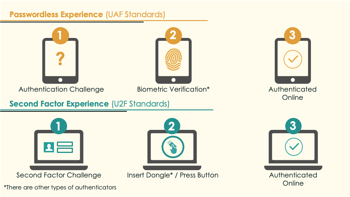
Second, for FIDO support, this architecture optionally includes two different types of authenticators: UAF and U2F. The FIDO Specifications Overview presentation [C2] explains the difference, as shown in Figure 2‑1.
Figure 2‑1 Comparison of UAF and U2F Standards
The following subsections address mobile device requirements to support SSO and FIDO authentication.
2.1.1 Supporting SSO on Android Devices
While it is not strictly required, the BCP recommends that the device provide an external user-agent that supports “in-application browser tabs,” which Google describes as the Android Custom Tab feature. The following excerpt is from the AppAuth Android-specific guidance in Appendix B.2 of RFC 8252:
Apps can initiate an authorization request in the browser without the user leaving the app, through the Android Custom Tab feature which implements the in-app browser tab pattern. The user’s default browser can be used to handle requests when no browser supports Custom Tabs.
Android browser vendors should support the Custom Tabs protocol (by providing an implementation of the “CustomTabsService” class), to provide the in-app browser tab user experience optimization to their users. Chrome is one such browser that implements Custom Tabs.
Any device manufacturer can support Custom Tabs in its Android browser. However, Google implemented this in its Chrome for Android web browser in September 2015 [C3]. Because Chrome is not part of the operating system (OS) itself but is downloaded from the Google Play Store, recent versions of Chrome can be used on older versions of Android. In fact, the Chrome Developer website’s page on Chrome Custom Tabs [C4] states that it can be used on Android Jelly Bean (4.1), which was released in 2012, and up.
To demonstrate SSO, the NCCoE reference architecture utilized the Motorola Solutions PSX App Suite, which requires Android Lollipop (5.0) or newer.
2.1.2 Supporting SSO on iOS Devices
Apple’s Safari browser is the default external user-agent provided on iOS devices, and iOS has also supported in-application browser tabs with the SFSafariViewController API [C5] since iOS 9. Like Chrome Custom Tabs, SFSafariViewController provides the functionality of the OS browser without exiting from the mobile application.
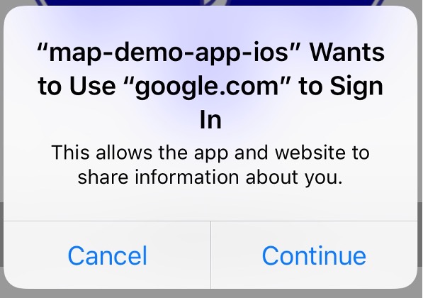
Apple made changes to its in-application browser tab implementation in iOS 11 [C6] that impacted SSO functionality. SFSafariViewController instances created by different applications are now effectively sandboxed from each other, with no shared cookie store between them. As described in Section 4.4 of Volume B of this practice guide, the AppAuth pattern depends on shared cookie storage to provide SSO between applications. Apple introduced a new API called SFAuthenticationSession to provide an in-application browser tab implementation specifically for authentication with SSO capabilities with access to the shared Safari cookie store. iOS also prompts for the user’s consent when SFAuthenticationSession is used. An example of the consent prompt is shown in Figure 2-2.
Figure 2‑2 SFAuthenticationSession Consent Prompt
In iOS 12, Apple replaced the SFAuthenticationSession API with ASWebAuthenticationSession [C7], which performs the same functions as SFAuthenticationSession and presents an identical consent prompt. In lab testing, the build team frequently encountered issues with SFAuthenticationSession where cookies created in an SFAuthenticationSession spawned by one application were not available in an SFAuthenticationSession spawned by another application. When this issue occurred, users would be prompted to authenticate in each application that was launched and SSO did not function properly. The team has not encountered these issues with ASWebAuthenticationSession, and the SSO capabilities of in-application browser tabs are much improved in iOS 12.
By default, the AppAuth library for iOS [C8] automatically selects an appropriate user-agent based on the version of iOS installed on the mobile device as shown in Table 2‑1.
Table 2‑1 AppAuth User-Agent by iOS Version
iOS Version |
User-Agent |
|---|---|
12 and higher |
ASWebAuthenticationSession |
11 |
SFAuthenticationSession |
9 or 10 |
SFSafariViewController |
8 and lower |
Safari |
The build team encountered issues with the FIDO UAF login flow demonstrated in this practice guide and the iOS in-application browser tab APIs (SFAuthenticationSession and ASWebAuthenticationSession). In the demo scenario, the login flow begins in the browser, which then launches the Passport application for user verification and FIDO authentication, and then control is returned to the browser to complete the authentication flow and return the user to the application. With ASWebAuthenticationSession, the authentication flow begins successfully in an in-application browser tab, and the user is redirected to the Passport application to authenticate, but control is not properly returned to the in-application browser tab when the Passport application closes. See Section 4.3.2 of Volume B of this practice guide for additional details about this issue. The build team speculates that this issue would generally apply to any login flow that entails launching an external application and then returning control to an in-application browser tab.
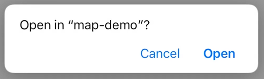
This issue was resolved by overriding the default user-agent selection in the AppAuth library. AppAuth provides the OIDExternalUserAgentIOSCustomBrowser interface to enable an application to specify the user-agent that should be used for the login flow. The iOS demo applications were configured to use the Safari browser instead of an in-application browser tab, which enabled the UAF login flow to succeed. The user experience with Safari is very similar to that with ASWebAuthenticationSession. The animation shown when transitioning to the web session is slightly different, and the consent dialogue shown in Figure 2‑2 is not shown. After authentication is completed, however, a different dialogue is displayed, prompting the user to open the mobile application as shown in Figure 2‑3.
Figure 2‑3 Safari Transition Prompt
2.1.3 Supporting FIDO U2F on Android Devices
The device will need the following components for FIDO U2F:
a web browser compatible with FIDO U2F
a FIDO U2F client application capable of handling the challenge
Near Field Communication (NFC) hardware support
Chrome for Android [C9] is a U2F-compatible browser. Google has added U2F functionality to the Google Play Services component of Android [C10], so devices running Android 5 and later can natively support U2F authentication over NFC, Universal Serial Bus (USB), and Bluetooth Low Energy (BLE) with an over-the-air update to Play Services. To support U2F in the browser, the Google Authenticator application [C11] (available on Android Gingerbread [2.3.3] and up) must also be installed.
2.1.4 Supporting FIDO U2F on iOS Devices
At the time of writing, the U2F login flow demonstrated in this practice guide could not be implemented on iOS devices. Apple’s Core NFC APIs do not expose required functionality to implement U2F over NFC. Yubico has published an API enabling the YubiKey Neo to be used for authentication over NFC with an iOS device, but this implementation uses the one-time password authentication mechanism of the YubiKey, not the U2F protocol [C12]. BLE U2F authenticators can be paired and used with iOS devices, but their use has been limited. The Google Smart Lock application, which protects Google accounts with U2F authentication on iOS devices, is the only notable U2F implementation on iOS of which the build team is aware.
Yubico has announced development of an authenticator with a Lightning adapter, specifically targeting iOS and Mac devices; and a corresponding mobile software development kit (SDK) for iOS that could enable U2F authentication in native iOS applications [C13]. To enable the AppAuth login flow used in this practice guide, a U2F-capable browser is also needed. If Apple adds W3C Web Authentication support to the Safari browser, it may support U2F authentication over Lightning and BLE in the future. Apple has already added experimental support to the Safari Technology Preview release for Mac OS [C14].
2.1.5 Supporting FIDO UAF
Supporting FIDO UAF is fairly similar on Android and iOS devices. The device will need the following components for FIDO UAF:
a web browser
a FIDO UAF client application capable of handling the challenge
a FIDO UAF authenticator
These components are pictured in Figure 2‑4, which is from the FIDO UAF Architectural Overview [C15].
Figure 2‑4 FIDO UAF Architectural Overview
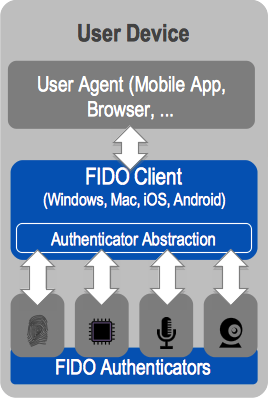
While the overview refers to the last two components (client and authenticator) as separate components, these components can—and often do—come packaged in a single application. The NCCoE reference architecture utilizes the Nok Nok Passport application for Android [C16] and iOS [C17] to provide these two components. In addition to the applications, the device will need to provide some hardware component to support the FIDO UAF authenticator. For example, for biometric-based FIDO UAF authenticators, a camera would be needed to support face or iris scanning, a microphone would be needed to support voice prints, and a fingerprint sensor would be needed to support fingerprint biometrics. Of course, if a personal identification number (PIN) authenticator is used, a specific hardware sensor is not required. Beyond the actual input method of the FIDO UAF factor, additional (optional) hardware considerations for a UAF authenticator include secure key storage for registered FIDO key pairs, storage of biometric templates, and execution of matching functions (e.g., within dedicated hardware or on processor trusted execution environments).
2.2 How to Install and Configure the Mobile Applications
This section covers the installation and configuration of the mobile applications needed for various components of the reference architecture: SSO, FIDO U2F, and FIDO UAF.
2.2.1 How to Install and Configure SSO-Enabled Applications
For SSO-enabled applications, there is no universal set of installation and configuration procedures; these will vary depending on the design choices of the application manufacturer. For the Android demo, the NCCoE reference architecture uses the Motorola Solutions PSX App Suite Version 5.4 [C18].
This PSX platform included several applications for the public safety community. Our setup consisted of three applications: PSX Messenger for text, photo, and video communication; PSX Mapping for shared location awareness; and PSX Cockpit to centralize authentication and identity information across the other applications. These applications cannot be obtained from a public venue (e.g., the Google Play Store); rather, the binaries must be obtained from Motorola Solutions and installed via other means, such as a Mobile Device Management (MDM) solution or private application store.
For the iOS demo, the team built two iOS demonstration applications—a mapping application called map-demo and a chat application called chat-demo. These applications were built by using Apple’s XCode integrated development environment and installed on lab devices using developer certificates.
2.2.1.1 Configuring the PSX Cockpit Application
Open the Cockpit application. Your screen should look like Figure 2‑5.
Figure 2‑5 PSX Cockpit Setup
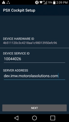
For DEVICE SERVICE ID, select a Device Service ID in the range given to you by your administrator. Note that these details will be provided by Motorola Solutions if you are using their service offering, or by your administrator if you are hosting the PSX application servers in your own environment. Each device should be configured with a unique Device Service ID corresponding to the username from the username range. For example, the NCCoE lab used a Device Service ID of 22400 to correspond to a username of 2400.
For SERVER ADDRESS, use the Server Address given to you by your administrator. For example, the NCCoE lab used a Server Address of uns5455.imw.motorolasolutions.com.
If a Use SUPL APN checkbox appears, leave it unchecked.
Tap NEXT. Your screen should look like Figure 2‑6.
Figure 2‑6 PSX Cockpit Setup, Continued
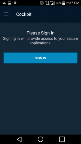
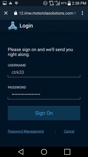
Tap SIGN IN.
Log in with the authentication procedure determined by the AS and IdP policies. Note that if UAF is used, a FIDO UAF authenticator must be enrolled before this step can be completed. See Section 2.2.3 for details on FIDO UAF enrollment. After you log in, your screen should look like Figure 2‑7.
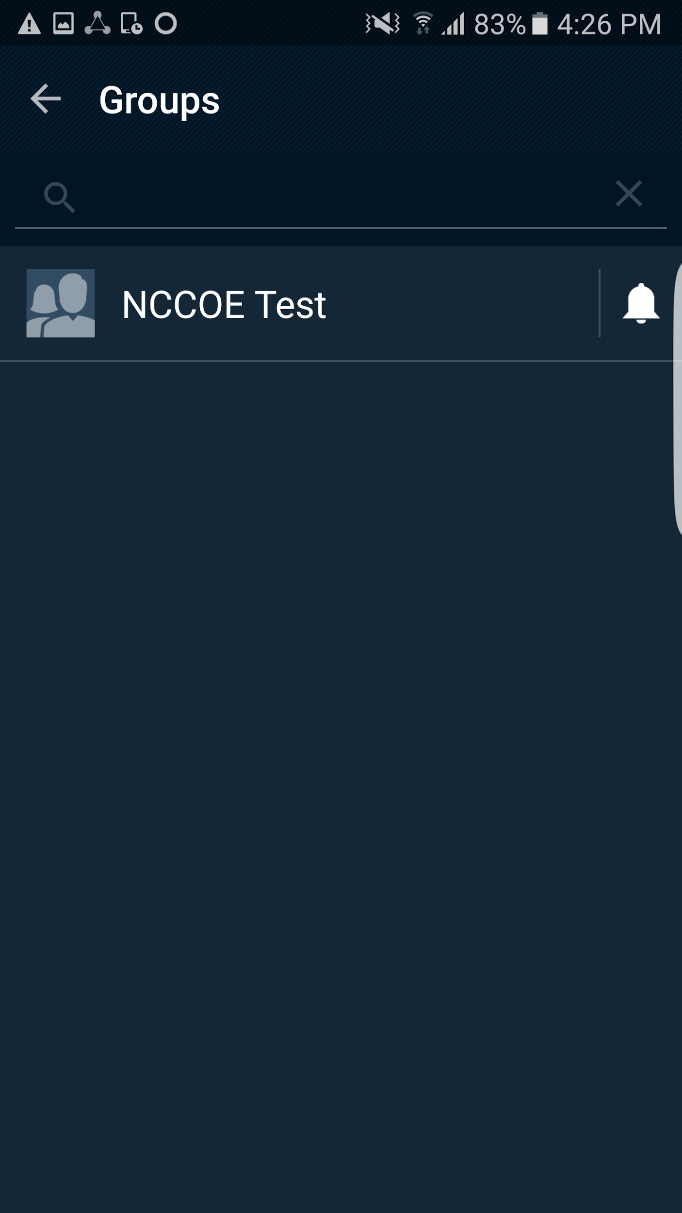
Figure 2‑7 PSX Cockpit Group List Selection
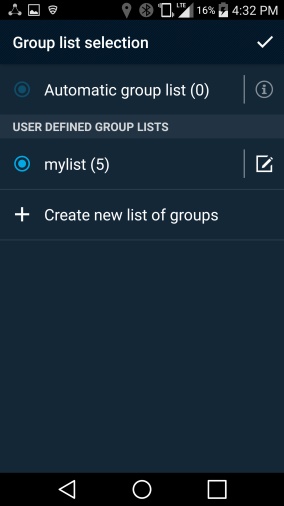
Tap Create new list of groups. This is used to select which organizationally defined groups of users you can receive data updates for in the other PSX applications.
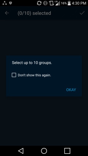
Tap OKAY. Your screen should look like Figure 2‑8.
Figure 2‑8 PSX Cockpit Groups
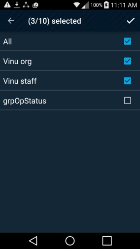
Check the checkboxes for the groups that you wish to use. Note that it may take a short time for the groups to appear.
Tap on the upper-right check mark. Your screen should look like Figure 2-9.
Figure 2‑9 PSX Cockpit Group List Setup Complete
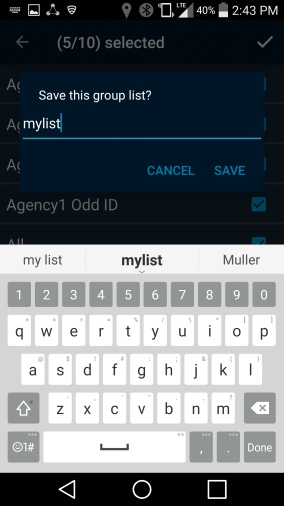
Enter a group list name (e.g., “mylist”), and tap SAVE.
Tap the upper-right check mark to select the list. Your screen should look like Figure 2-10.
Figure 2‑10 PSX Cockpit User Interface
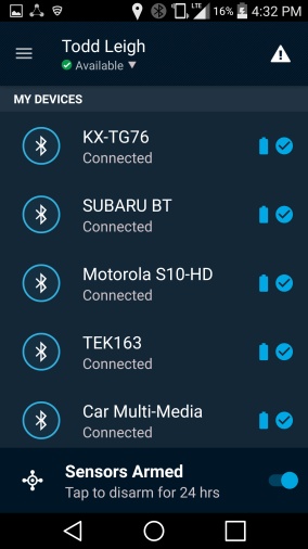
On the Cockpit screen, you can trigger an emergency (triangle icon in the upper right). Set your status (drop-down menu under your name); or reselect roles and groups, see configuration, and sign off (hamburger menu to the left of your name, and then tap username).
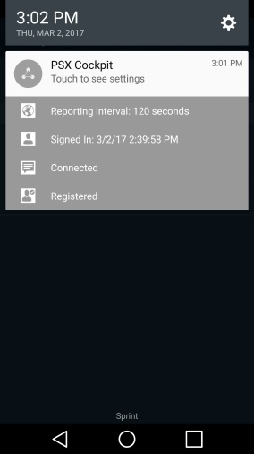
If you pull down your notifications, you should see icons and text indicating Reporting interval: 120 seconds, Signed In: <date> <time>, Connected, and Registered.
2.2.1.2 Configuring the PSX Mapping Application
Open the Mapping application. You should see the screen shown in Figure 2-11.
Figure 2‑11 PSX Mapping User Interface
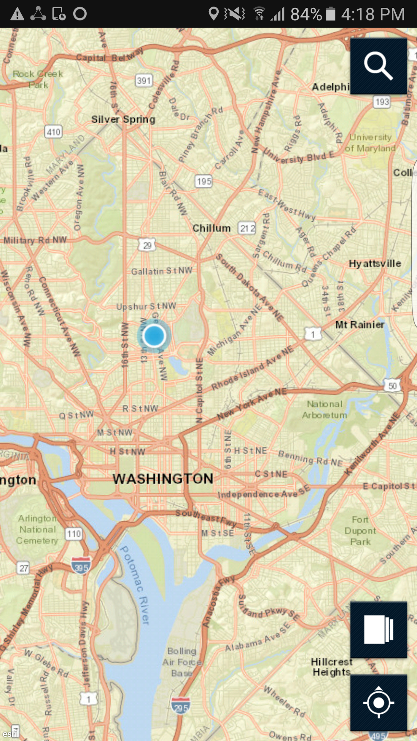
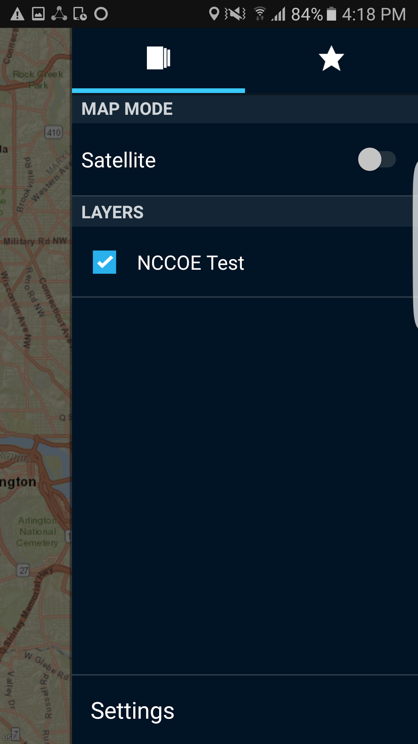
Select the Layers icon in the lower‑right corner. Group names should appear under Layers.
Select a group. Your screen should look like Figure 2-12.
Figure 2‑12 PSX Mapping Group Member Information
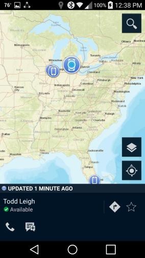
The locations of the devices that are members of that group should appear as dots on the map.
Select a device. A pop-up will show the user of the device and icons for phoning and messaging that user.
Selecting the Messenger icon for the selected user will take you to the Messenger application, where you can send a message to the user.
2.2.1.3 Configuring the PSX Messenger Application
Open the Messenger application. Your screen should look like Figure 2‑13.
Figure 2‑13 PSX Messenger User Interface

Your screen should show People and Groups. Select one of them.
A list of people or groups to which you can send a message should appear. Select one of them. Your screen should look like Figure 2‑14.
Figure 2‑14 PSX Messenger Messages
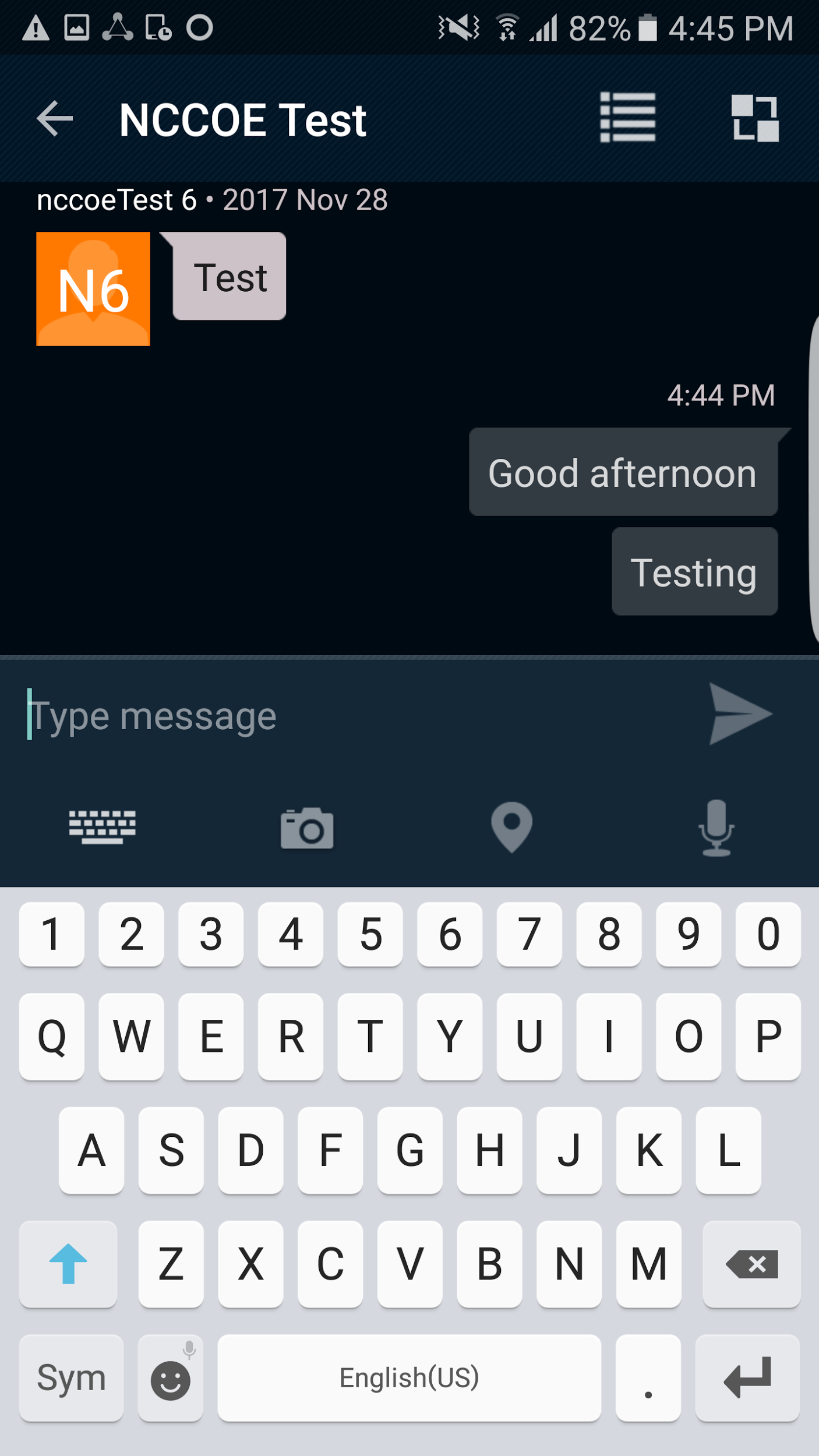
You are now viewing the messaging window. You can type text for a message and attach a picture, video, voice recording, or map.
Tap the Send icon. The message should appear on your screen.
Tap the Pivot icon in the upper‑right corner of the message window. Select Locate, and you will be taken to the Mapping application with the location of the people or group you selected.
2.2.2 How to Install and Configure a FIDO U2F Authenticator
This section covers the installation and usage of a FIDO U2F authenticator on an Android mobile device. As explained in Section 2.1.4, the U2F login flow is not supported on iOS devices. The NCCoE reference architecture utilizes the Google Authenticator application on the mobile device and a Yubico YubiKey NEO as a hardware token. The application provides an interface between the Chrome browser and the U2F capabilities built into Play Services and is available on Google’s Play Store [C11].
2.2.2.1 Installing Google Authenticator
On your Android device, open the Play Store application.
Search for Google Authenticator, and install the application. There is no configuration needed until you are ready to register a FIDO U2F token with a StrongKey server.
2.2.2.2 Registering the Token
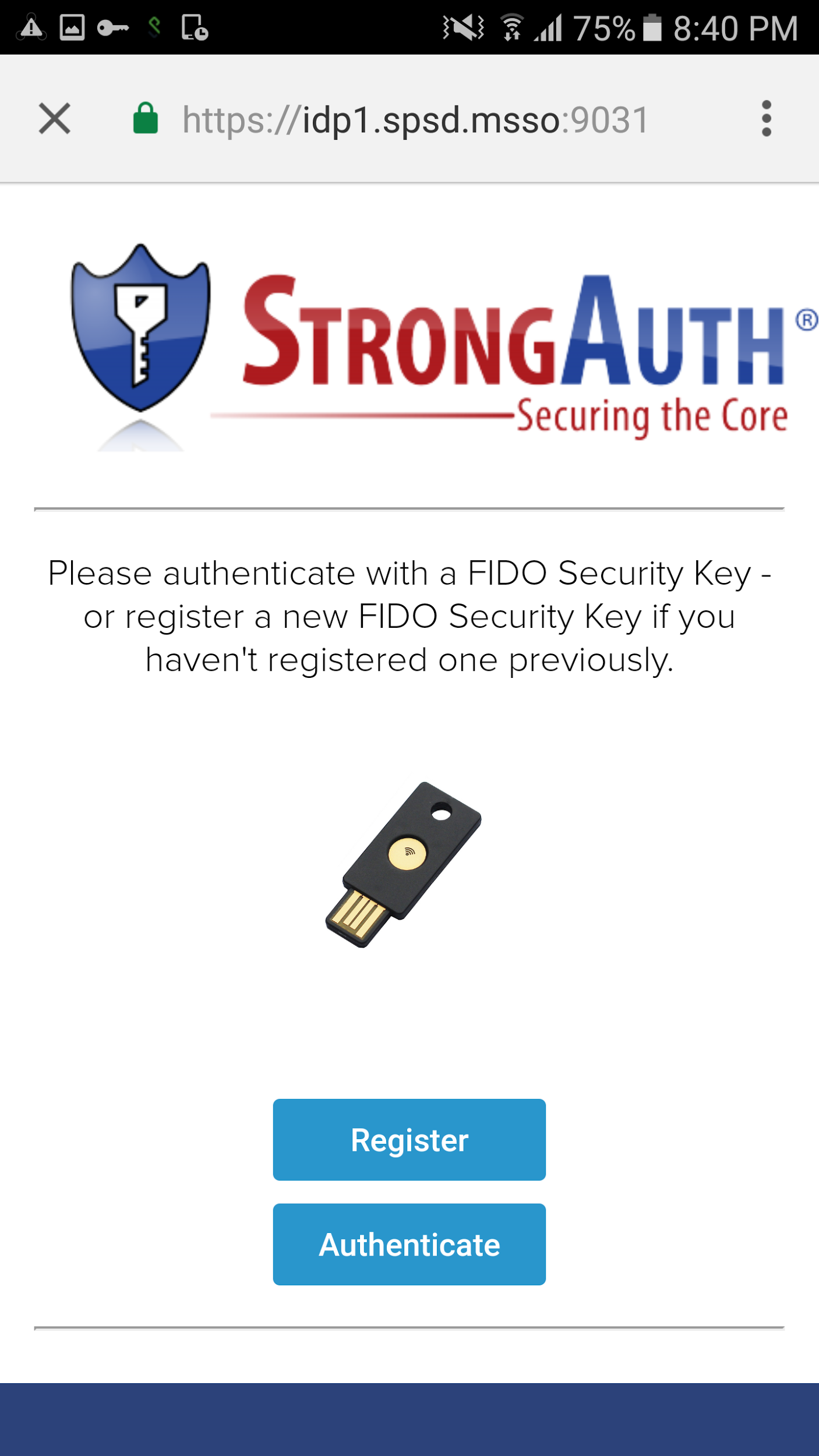
In the architecture that is laid out in this practice guide, there is no out-of-band process to register the user’s U2F token. This takes place the first time the user tries to log in with whatever SSO-enabled application they are using. For instance, when using the PSX Cockpit application, once the user tries to sign into an IdP that has U2F enabled and has successfully authenticated with a username and password, they will be presented with the screen shown in Figure 2‑15.
Figure 2‑15 FIDO U2F Registration
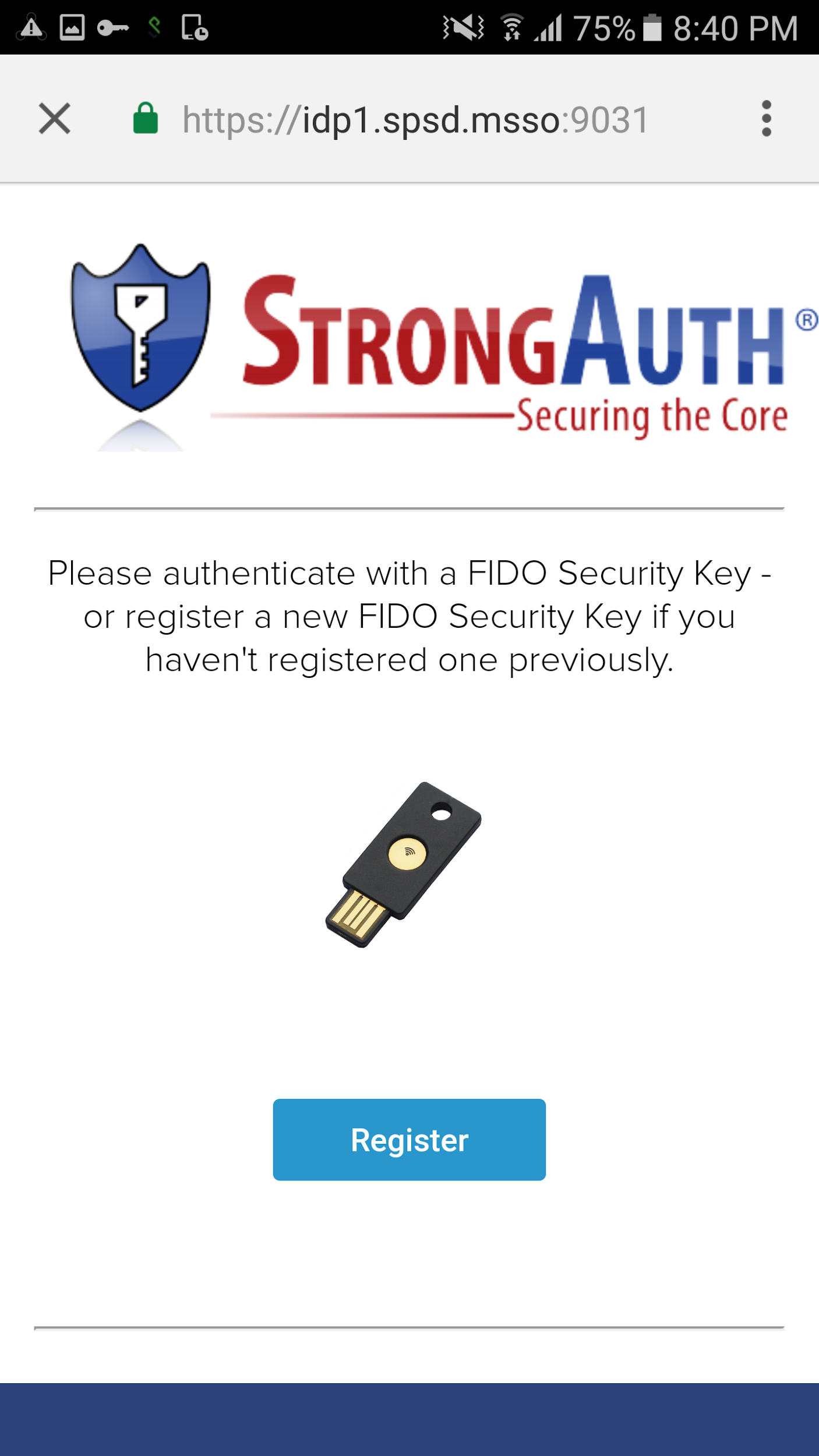
Because the user has never registered a U2F token, that is the only option the user sees.
Click Register, and the web page will activate the Google Authenticator application, which asks you to use a U2F token to continue (Figure 2‑15 above).
Hold the U2F token to your device, and the token will be registered to your account and you will be redirected to the U2F login screen again.
2.2.2.3 Authenticating with the Token
Now, because the system has a U2F token on file for the user, the user has the option to authenticate.
Click Authenticate (Figure 2‑16), and the Google Authenticator application will be activated once more.
Hold the U2F token to your device, and then the authentication will be successful and the SSO flow will continue.
Figure 2‑16 FIDO U2F Authentication
2.2.3 How to Install and Configure a FIDO UAF Client
This section covers the installation and usage of a FIDO UAF client on the mobile device. Any FIDO UAF client can be used, but the NCCoE reference architecture utilizes the Nok Nok Passport application (hereafter referred to as “Passport”). The Passport application functions as the client-side UAF application and is available on Google’s Play Store [C16] and Apple’s App Store [C17]. The following excerpt is from the Play Store page:
Passport from Nok Nok Labs is an authentication app that supports the Universal Authentication Framework (UAF) protocol from the FIDO Alliance (www.fidoalliance.org).
Passport allows you to use out-of-band authentication to authenticate to selected websites on a laptop or desktop computer. You can use the fingerprint sensor on FIDO UAF-enabled devices (such as the Samsung Galaxy S® 6, Fujitsu Arrows NX, or Sharp Aquos Zeta) or enter a simple PIN on non-FIDO enabled devices. You can enroll your Android device by using Passport to scan a QR code displayed by the website, then touch the fingerprint sensor or enter a PIN. Once enrolled, you can authenticate using a similar method. Alternatively, the website can send a push notification to your Android device and trigger the authentication.
This solution lets you use your Android device to better protect your online account, without requiring passwords or additional hardware tokens.
In our reference architecture, we used a Quick Response (QR) code to enroll the device onto Nok Nok Labs’ test server.
2.2.3.1 Installing Passport on Android
On your Android device, open the Play Store application.
Search for Nok Nok Passport, and install the application. There is no configuration needed until you are ready to enroll the device with a Nok Nok Labs server.
Normally, the user will never need to open the Passport application during authentication; it will automatically be invoked by the SSO-enabled application (e.g., PSX Cockpit). Instead of entering a username and password into a Chrome Custom Tab, the user will be presented with the Passport screen to use the user’s UAF credential.
2.2.3.2 Installing Passport on iOS
On your iOS device, open the App Store application.
Search for Nok Nok Passport, and install the application. There is no configuration needed until you are ready to enroll the device with a Nok Nok Labs server.
As with the Android application, the Passport application for iOS is invoked automatically during login with a UAF-enabled server.
2.2.3.3 Enrolling the Device
This section details the steps to enroll a device to an NNAS. First, you need a device that has Passport installed. Second, you need to use another computer (preferably a desktop or laptop) to interact with your NNAS web interface.
Note: Users are not authenticated during registration. We are using the “tutorial” application provided with the NNAS. This sample implementation does not meet the FIDO requirement of authentication prior to registration. The production version of the NNAS may require additional steps and may have a different interface.
Screenshots that demonstrate the enrollment process are shown in Figure 2‑17 through Figure 2‑24.
First, use your computer to navigate to the NNAS web interface. You will be prompted for a username and password; enter your administrator credentials and click Log In (Figure 2‑17).
Figure 2‑17 Nok Nok Labs Tutorial Application Authentication
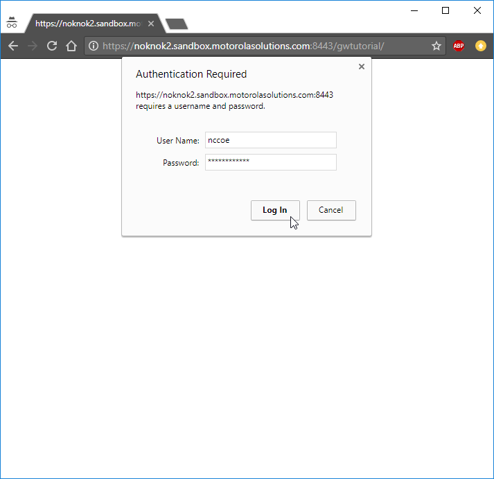
Once you have logged in to the NNAS as an administrator, you need to identify which user you want to manage. Enter the username and click Login (Figure 2‑18).
Note: As stated above, this is the tutorial application, so it prompts for only a username, not a password. A production environment would require user authentication.
Figure 2‑18 Nok Nok Labs Tutorial Application Login
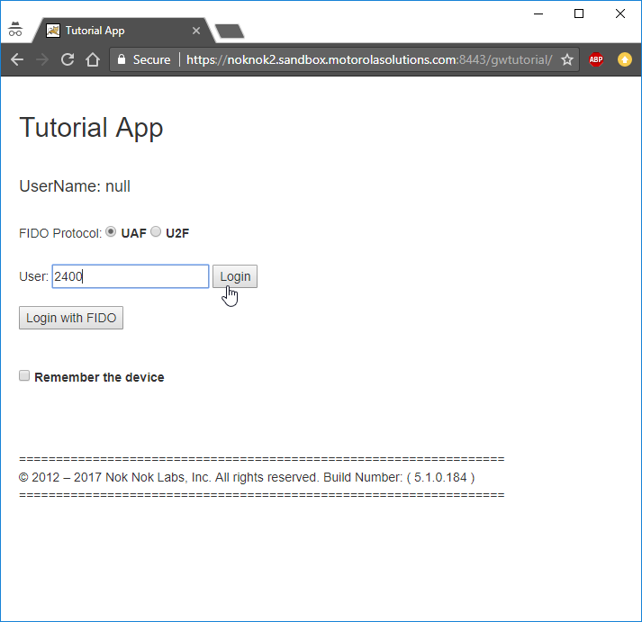
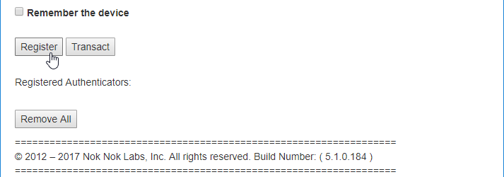
Once you have selected the user, you will need to start the FIDO UAF registration process. To begin, click Register (Figure 2‑19).
Figure 2‑19 FIDO UAF Registration Interface
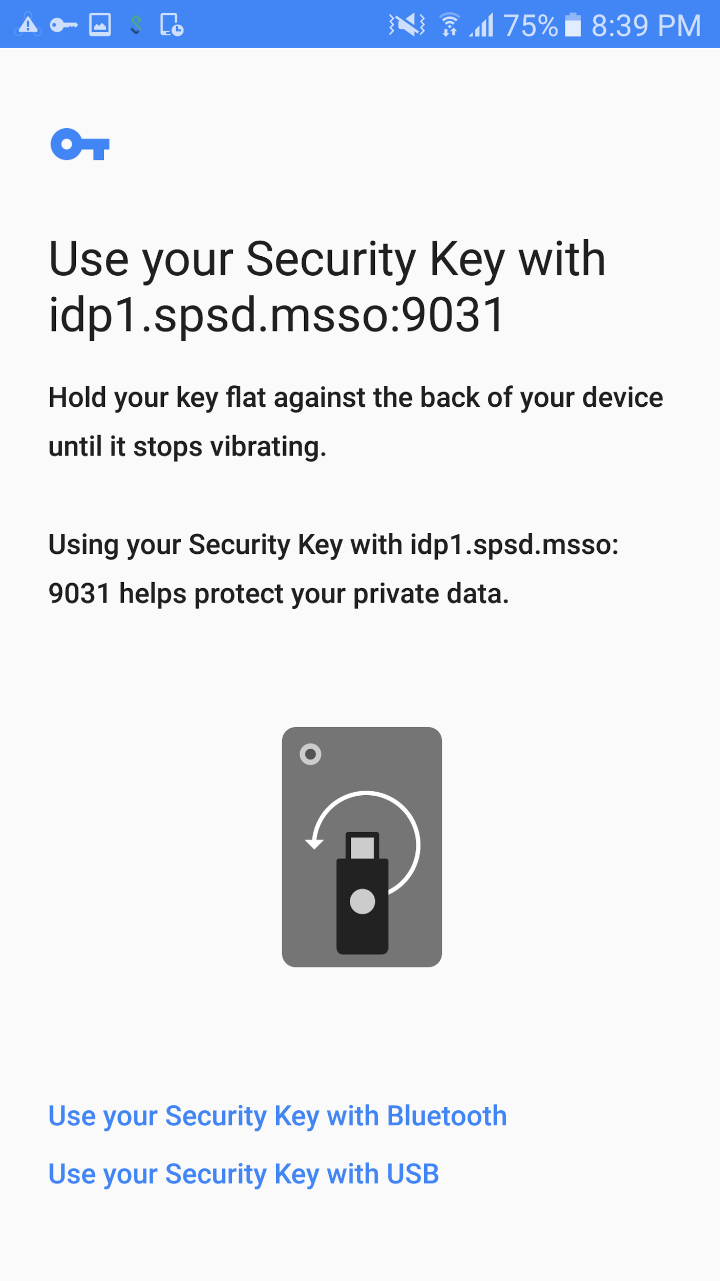
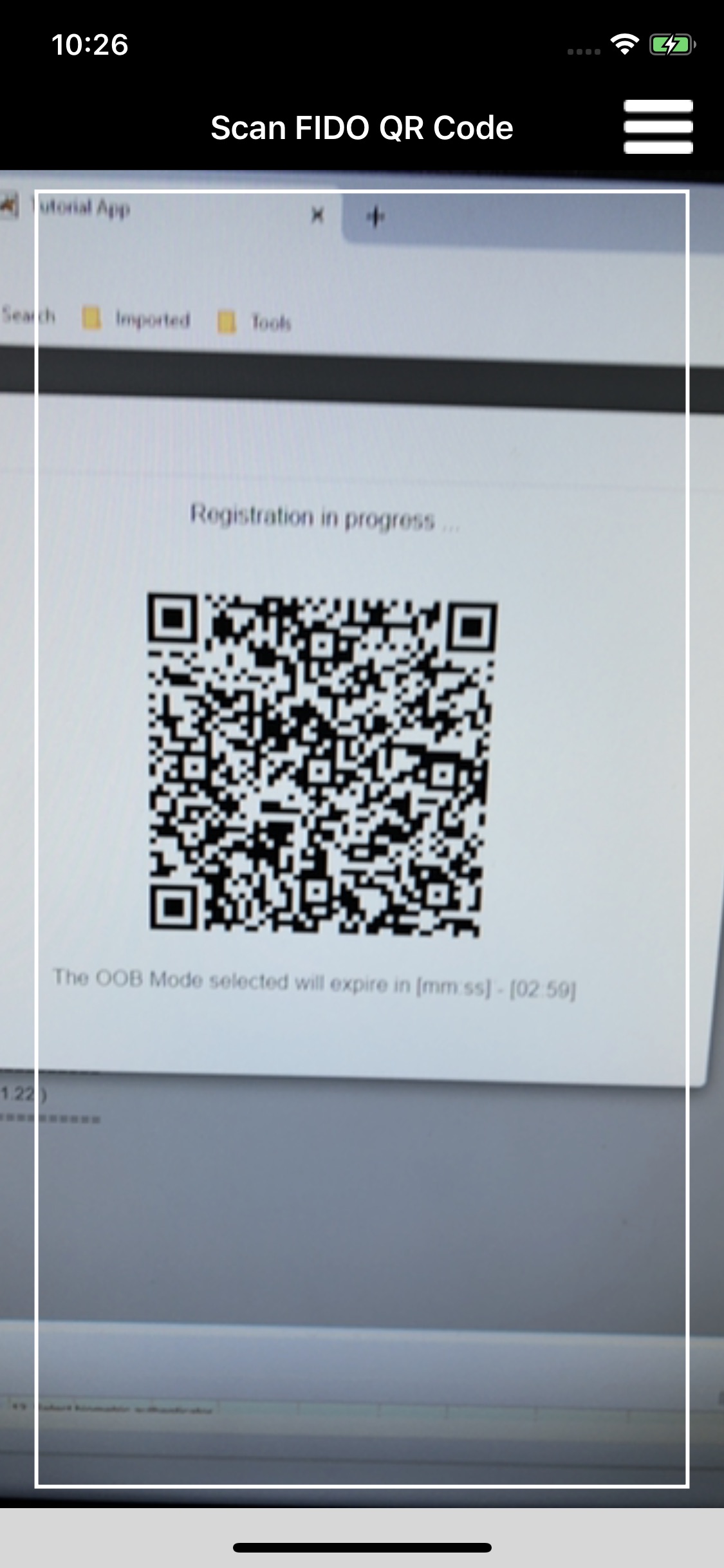
You will see a window with a QR code and a countdown (Figure 2‑20). You have three minutes to finish the registration process with your device.
Once the QR image appears, launch the Passport application on the phone. The Passport application activates the device camera to enable capturing the QR code by centering the code in the square frame in the middle of the screen (Figure 2‑21).
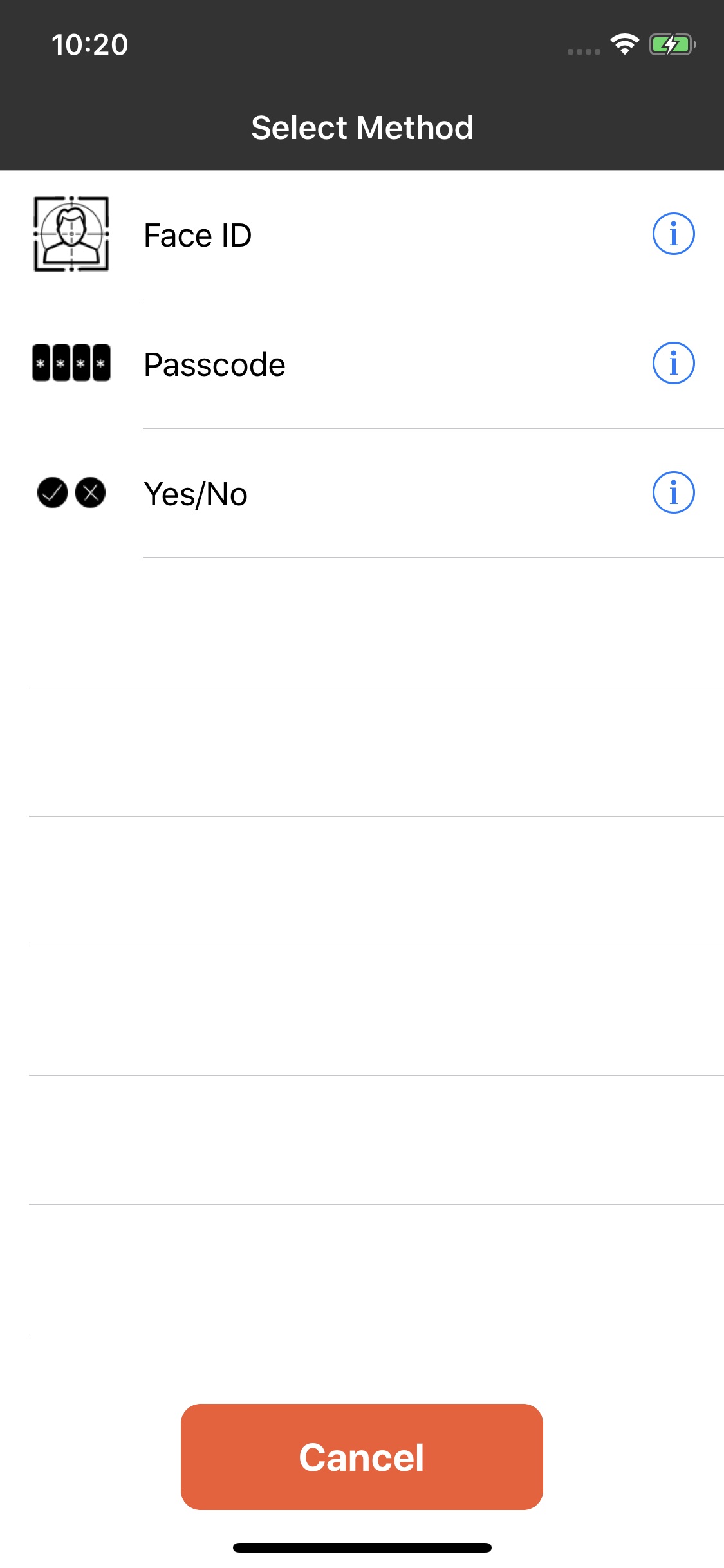
Once the QR code is scanned, the application prompts the user to select the type of verification (fingerprint, PIN, etc.) to use (Figure 2‑21). The selections may vary based on the authenticator modules installed on the device. Figure 2‑21 shows the Passport application on an Android device. Figure 2‑22 shows the same flow on an iOS device. On iOS devices that support Face ID, such as the iPhone X, Face ID is available as a user verification option.
Figure 2‑20 FIDO UAF Registration QR Code
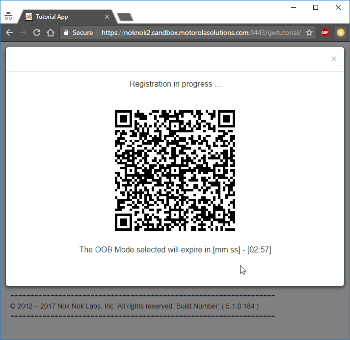
Figure 2‑21 FIDO UAF Registration Device Flow, Android Device
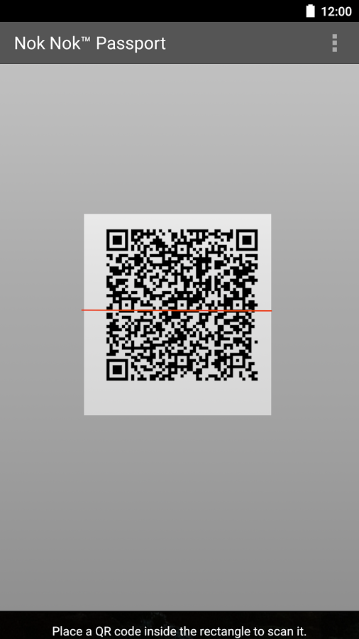
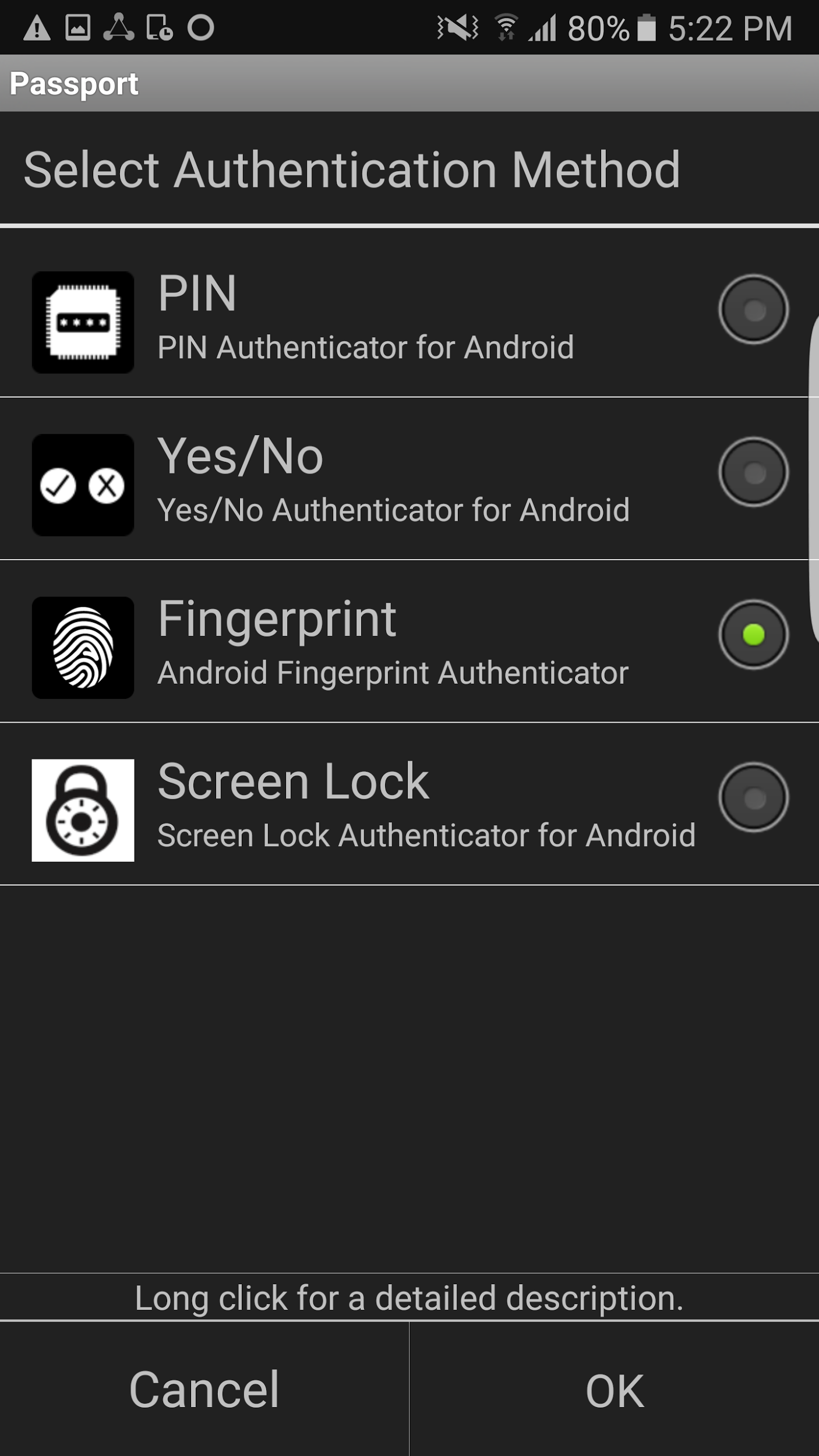
Figure 2‑22 FIDO UAF Registration Device Flow, iPhone X
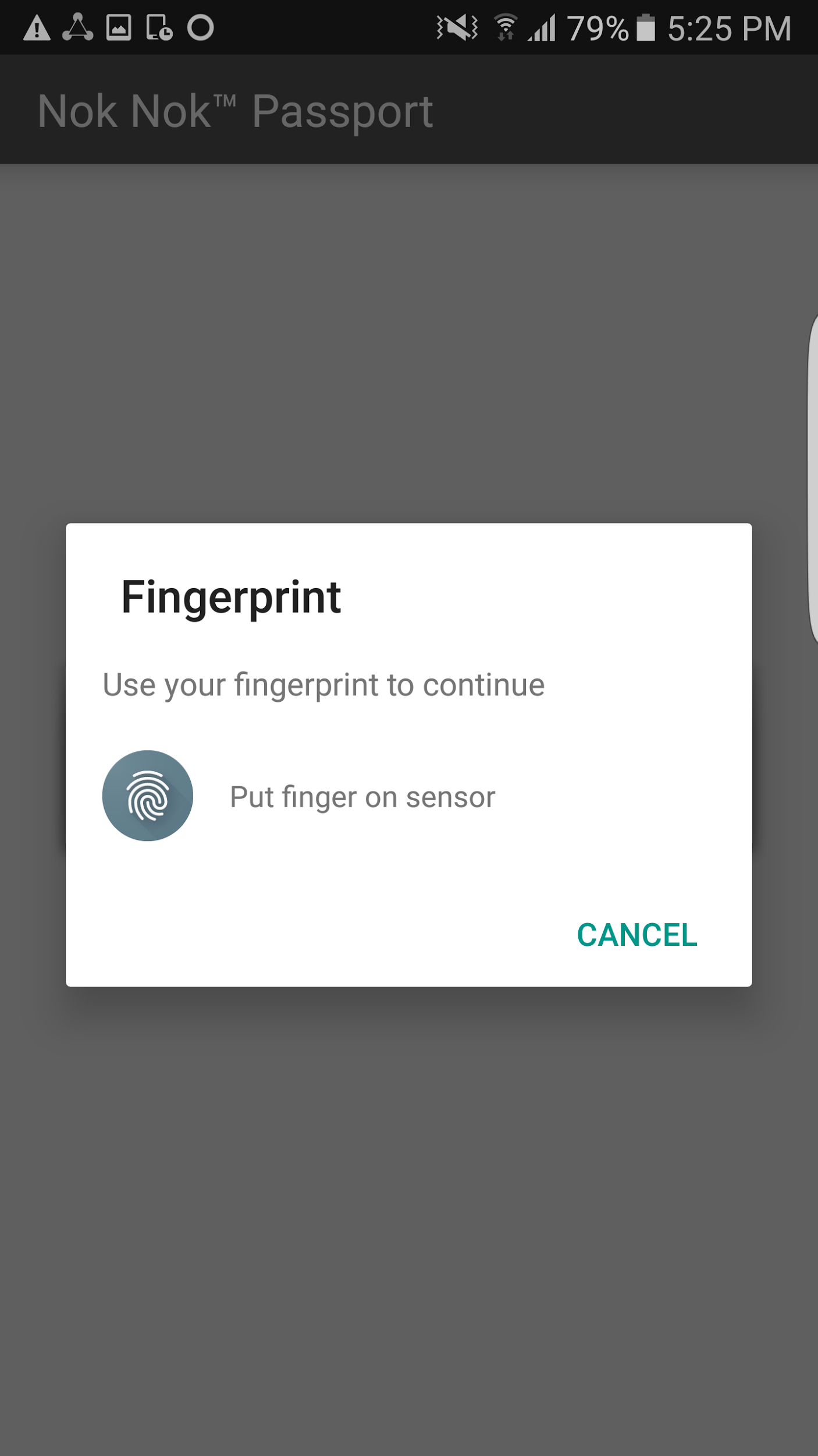
The user is then prompted to perform user verification with the selected method. In the example shown in Figure 2‑23, a fingerprint authenticator is registered. The user is prompted for a fingerprint scan to complete registration. The fingerprint authenticator uses a fingerprint previously registered in the Android screen‑lock settings. If a PIN authenticator were registered, the user would be prompted to set a PIN instead.
Figure 2‑23 FIDO UAF Fingerprint Authenticator, Android Device
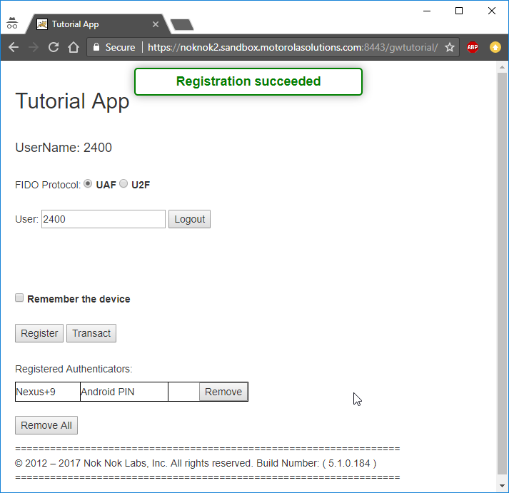
If user verification is successful, then a new UAF key pair is generated, the public key is sent to the server, and registration is completed (Figure 2‑24).
Figure 2‑24 FIDO UAF Registration Success
2.3 How Application Developers Must Integrate AppAuth for SSO
Application developers can easily integrate AppAuth to add SSO capabilities to their applications. The first step to doing this is reading through the documentation on GitHub for AppAuth for Android [C19] or iOS [C8]. After doing so, an application developer can begin the integration of AppAuth. The degree of this integration can vary—for instance, you may choose to utilize user attributes to personalize the user’s application experience. The following sections describe AppAuth integration for Android and iOS applications.
For either platform, the mobile application must be registered with the OAuth AS and given a client ID as described in Section 3.3. The client ID will be needed when building the mobile application.
2.3.1 AppAuth Integration for Android
In this example, we use Android Studio 3.0, Android Software Development Kit 25, and Gradle 2.14.1.
2.3.1.1 Adding the Library Dependency
Edit your application’s build.gradle file, and add this line to its dependencies (note that the AppAuth library will most likely be updated in the future, so you should use the most recent version for your dependency, not necessarily the one in this document):
===============================================================================
dependencies {
...
    compile 'net.openid:appauth:0.7.0'
}
===============================================================================
2.3.1.2 Adding Activities to the Manifest
First, you need to identify your AS’s host name, OAuth redirect path, and what scheme was set when you registered your application. The scheme here is contrived, but it is common practice to use reverse DNS style names; you should choose whatever aligns with your organization’s common practices. Another alternative to custom schemes is to use App Links.
Edit your AndroidManifest.xml file, and add these lines:
===============================================================================
<manifest xmlns:android="http://schemas.android.com/apk/res/android"
    xmlns:tools="http://schemas.android.com/tools"
    package="com.example.app">
...
        <activity
            android:name="net.openid.appauth.RedirectUriReceiverActivity"
            tools:node="replace">
            <intent-filter>
                <action android:name="android.intent.action.VIEW" />
                <category android:name="android.intent.category.DEFAULT" />
                <category android:name="android.intent.category.BROWSABLE" />
                <data
                    android:host="as.example.com"
                    android:path="/oauth2redirect"
                    android:scheme="myappscheme" />
            </intent-filter>
        </activity>
        <activity android:name=".activity.AuthResultHandlerActivity" />
        <activity android:name=".activity.AuthCanceledHandlerActivity" />
    </application>
</manifest>
===============================================================================
2.3.1.3 Creating Activities to Handle Authorization Responses
Create a utility class for reusable code (Utility), and create activities to handle successful authorizations (AuthResultHandlerActivity) and canceled authorizations (AuthCanceledHandlerActivity):
===============================================================================
public class Utility {
    public static AuthorizationService getAuthorizationService(Context context) {
        AppAuthConfiguration appAuthConfig = new AppAuthConfiguration.Builder()
                .setBrowserMatcher(new BrowserWhitelist(
                        VersionedBrowserMatcher.CHROME_CUSTOM_TAB,
                        VersionedBrowserMatcher.SAMSUNG_CUSTOM_TAB))
                // the browser matcher above allows you to choose which in-app browser
                // tab providers will be supported by your app in its OAuth2 flow
                .setConnectionBuilder(new ConnectionBuilder() {
                    @NonNull
                    public HttpURLConnection openConnection(@NonNull Uri uri)
                            throws IOException {
                        URL url = new URL(uri.toString());
                        HttpURLConnection connection =
                                (HttpURLConnection) url.openConnection();
                        if (connection instanceof HttpsURLConnection) {
                            // optional: use your own trust manager to set a custom
                            // SSLSocketFactory on the HttpsURLConnection
                        }
                        return connection;
                    }
                }).build();

        return new AuthorizationService(context, appAuthConfig);
    }

    public static AuthState restoreAuthState(Context context) {
        // we use SharedPreferences to store a String version of the JSON
        // Auth State, and here we retrieve it to convert it back to a POJO
        SharedPreferences sharedPreferences =
                PreferenceManager.getDefaultSharedPreferences(context);
        String jsonString = sharedPreferences.getString("AUTHSTATE", null);
        if (!TextUtils.isEmpty(jsonString)) {
            try {
                return AuthState.jsonDeserialize(jsonString);
            } catch (JSONException jsonException) {
                // handle this appropriately
            }
        }
        return null;
    }
}
===============================================================================
public class AuthResultHandlerActivity extends Activity {

    private static final String TAG = AuthResultHandlerActivity.class.getName();

    private AuthState mAuthState;
    private AuthorizationService mAuthService;

    @Override
    protected void onCreate(Bundle savedInstanceState) {
        super.onCreate(savedInstanceState);

        AuthorizationResponse res = AuthorizationResponse.fromIntent(getIntent());
        AuthorizationException ex = AuthorizationException.fromIntent(getIntent());
        mAuthState = new AuthState(res, ex);
        mAuthService = Utility.getAuthorizationService(this);

        if (res != null) {
            Log.d(TAG, "Received AuthorizationResponse");
            performTokenRequest(res.createTokenExchangeRequest());
        } else {
            Log.d(TAG, "Authorization failed: " + ex);
        }
    }

    @Override
    protected void onDestroy() {
        super.onDestroy();
        mAuthService.dispose();
    }

    private void performTokenRequest(TokenRequest request) {
        TokenResponseCallback callback = new TokenResponseCallback() {
            @Override
            public void onTokenRequestCompleted(
                    TokenResponse tokenResponse,
                    AuthorizationException authException) {
                receivedTokenResponse(tokenResponse, authException);
            }
        };
        mAuthService.performTokenRequest(request, callback);
    }

    private void receivedTokenResponse(TokenResponse tokenResponse,
                                       AuthorizationException authException) {
        Log.d(TAG, "Token request complete");
        if (tokenResponse != null) {
            mAuthState.update(tokenResponse, authException);

            // persist auth state to SharedPreferences
            PreferenceManager.getDefaultSharedPreferences(this)
                    .edit()
                    .putString("AUTHSTATE", mAuthState.jsonSerializeString())
                    .commit();

            String accessToken = mAuthState.getAccessToken();
            if (accessToken != null) {
                // optional: pull claims out of JWT (name, etc.)
            }
        } else {
            Log.d(TAG, "  ", authException);
        }
    }
}
===============================================================================
public class AuthCanceledHandlerActivity extends Activity {

    private static final String TAG = AuthCanceledHandlerActivity.class.getName();

    @Override
    protected void onCreate(Bundle savedInstanceState) {
        super.onCreate(savedInstanceState);

        Log.d(TAG, "OpenID Connect authorization flow canceled");

        // go back to MainActivity
        finish();
    }
}
===============================================================================
2.3.1.4 Executing the OAuth 2 Authorization Flow
In whatever activity you are using to initiate authentication, add the necessary code to use the AppAuth SDK to execute the OAuth 2 authorization flow:
===============================================================================
...

// some method, usually a "login" button, activates the OAuth2 flow

String OAUTH_AUTH_ENDPOINT = "https://as.example.com:9031/as/authorization.oauth2";
String OAUTH_TOKEN_ENDPOINT = "https://as.example.com:9031/as/token.oauth2";
String OAUTH_REDIRECT_URI = "myappscheme://app.example.com/oauth2redirect";
String OAUTH_CLIENT_ID = "myapp";
String OAUTH_PKCE_CHALLENGE_METHOD = "S256"; // options are "S256" and "plain"

// CREATE THE SERVICE CONFIGURATION
AuthorizationServiceConfiguration config = new AuthorizationServiceConfiguration(
        Uri.parse(OAUTH_AUTH_ENDPOINT), // auth endpoint
        Uri.parse(OAUTH_TOKEN_ENDPOINT), // token endpoint
        null // registration endpoint
);

// OPTIONAL: Add any additional parameters to the authorization request
HashMap<String, String> additionalParams = new HashMap<>();
additionalParams.put("acr_values", "urn:acr:form");

// BUILD THE AUTHORIZATION REQUEST
AuthorizationRequest.Builder builder = new AuthorizationRequest.Builder(
        config,
        OAUTH_CLIENT_ID,
        ResponseTypeValues.CODE,
        Uri.parse(OAUTH_REDIRECT_URI))
        .setScopes("profile") // scope is optional, set whatever is needed by your app
        .setAdditionalParameters(additionalParams);

// SET UP PKCE CODE VERIFIER
String codeVerifier = CodeVerifierUtil.generateRandomCodeVerifier();
String codeVerifierChallenge = CodeVerifierUtil.deriveCodeVerifierChallenge(codeVerifier);
builder.setCodeVerifier(codeVerifier, codeVerifierChallenge,

        OAUTH_PKCE_CHALLENGE_METHOD);

AuthorizationRequest request = builder.build();

// PERFORM THE AUTHORIZATION REQUEST
// this pauses and leaves the current activity
Intent postAuthIntent = new Intent(this, AuthResultHandlerActivity.class);
Intent authCanceledIntent = new Intent(this, AuthCanceledHandlerActivity.class);
mAuthService.performAuthorizationRequest(
        request,
        PendingIntent.getActivity(this, request.hashCode(), postAuthIntent, 0),
        PendingIntent.getActivity(this, request.hashCode(), authCanceledIntent, 0));

...

// when the activity resumes, check if the OAuth2 flow was successful

@Override
protected void onResume() {
    super.onResume();

    AuthState authState = Utility.restoreAuthState(this);
    if (authState != null) {
        // we are authorized!
        // proceed to the next activity that requires an access token
    }
}

...
===============================================================================
2.3.1.5 Fetching and Using the Access Token
After you have proceeded from the prior activity, you can fetch your access token. If some time has passed since you obtained the access token, you may need to use your refresh token to get a new access token. AppAuth handles both cases the same way. Implement the following code wherever you need to use the access token:
===============================================================================
...

// assuming we have an instance of a Context as mContext...
// ensure we have a fresh access token to perform any future actions
final AuthorizationService authService = Utility.getAuthorizationService(mContext);
AuthState authState = Utility.restoreAuthState(mContext);
authState.performActionWithFreshTokens(authService, new AuthState.AuthStateAction() {
    @Override
    public void execute(String accessToken, String idToken,
            AuthorizationException ex) {
        JWT jwt = null;
        if (ex != null) {
            // negotiation for fresh tokens failed, check ex for more details
        } else {
            // we can now use accessToken to access remote services
            // this is typically done by including the token in an HTTP header,
            // or in a handshake transaction if another transport protocol is used
        }
        authService.dispose();
    }
});

...
===============================================================================
2.3.2 AppAuth Integration for iOS
The iOS demo applications were built with XCode 10.1 for iOS deployment target 11.0. using the Swift programming language.
2.3.2.1 Adding the Library Dependency
The AppAuth library can be added to an XCode project by using either the CocoaPods or Carthage dependency manager. The CocoaPods method automatically uses the official released version of the library. To use a particular code branch or to get recent updates not available in the release version, Carthage must be used. The official release should be suitable for the majority of applications.
To add the AppAuth library by using CocoaPods:
Create a Podfile in the root directory of the project. The following is a sample Podfile from the maps-demo application that adds AppAuth and two other libraries.
===============================================================================
source 'https://github.com/CocoaPods/Specs.git'
target 'map-demo-app-ios' do
    pod 'GoogleMaps'
    pod 'GooglePlaces'
    pod 'AppAuth'
end
===============================================================================
Open a terminal, navigate to the root directory of the project, and run the command:
pod installIn XCode, close any open projects. Click File-Open, navigate to the root of the project, and open the file <project-name>.xcworkspace.
To add the AppAuth library by using Carthage:
Create a Cartfile with the following contents in the root directory of the project:
===============================================================================
github "openid/AppAuth-iOS" "master"
===============================================================================
Open a terminal, navigate to the root directory of the project, and run the command:
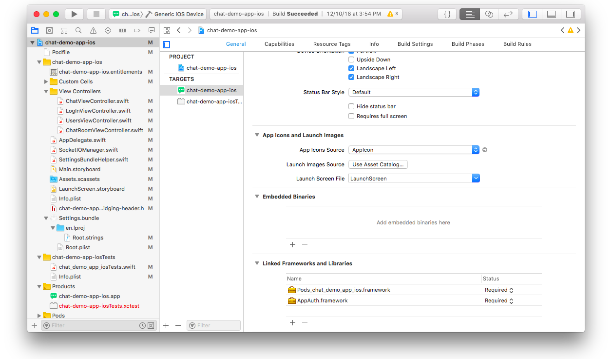
carthage bootstrapIn XCode, click on the project in the project navigator and select the General tab. Under Linked Frameworks and Libraries, click the plus icon to add a framework.
Click Add Other…. A file selection dialogue should open and display the root folder of the project. Navigate to the Carthage/Build/iOS subfolder, select AppAuth.framework, and click Open. The Frameworks and Libraries interface is shown in Figure 2‑25.
Figure 2‑25 Linked Frameworks and Libraries
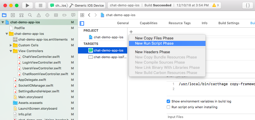
On the Build Phases tab, click the plus icon in the top left corner of the editor and select New Run Script Phase as shown in Figure 2‑26.
Figure 2‑26 Creating a New Run Script Phase
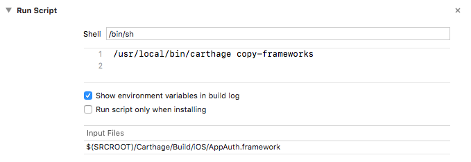
Add the following command to the Run Script:
/usr/local/bin/carthage copy-frameworksClick the plus icon under Input Files and add the following entry:
$(SRCROOT)/Carthage/Build/iOS/AppAuth.framework
Figure 2‑27 shows a completed Run Script.
Figure 2‑27 Carthage Run Script
Once either of the above procedures is completed, you should be able to import AppAuth into your project without compiler errors.
2.3.2.2 Registering a Custom URL Scheme
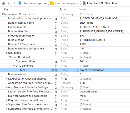
To enable the AS to send a redirect through the browser back to your mobile application, you must either register a custom URL scheme or use Universal Links. This example shows the use of a custom URL scheme. This scheme must be included in the redirect_uri registered with the AS; see Section 3.3 for details on OAuth client registration. To configure the custom URL scheme:
In the XCode Project Navigator, select the Info.plist file.
Select URL Types and click the Plus icon to add a type.
Under the created item, click on the selector icon and choose URL Schemes.
Edit the item value to match the URL scheme. Figure 2‑28 shows a custom URL scheme of “org.mitre.chatdemo.”
Figure 2‑28 Custom URL Scheme
2.3.2.3 Handling Authorization Responses
Add the following lines to AppDelegate.swift to handle authorization responses submitted to your application’s redirect_uri:
===============================================================================
var currentAuthorizationFlow:OIDAuthorizationFlowSession?
func application(_ app: UIApplication, open url: URL, options:
[UIApplicationOpenURLOptionsKey : Any] = [:]) -> Bool {
      if let authorizationFlow = self.currentAuthorizationFlow,
      authorizationFlow.resumeAuthorizationFlow(with: url) {
         self.currentAuthorizationFlow = nil
         return true
      }
      return false
}
===============================================================================
2.3.2.4 Executing the OAuth 2 Authorization Flow
In the View Controller that handles authentication events, add the necessary code to use AppAuth to submit authorization requests to the AS. The configuration parameters for the AS, such as the URLs for the authorization and token endpoints, can be automatically discovered if the AS supports OpenID Connect Discovery; otherwise, these parameters must be provided either in settings or in the code. In this example, they are specified in the code. This example also demonstrates how to specify the user-agent for the authorization flow; in this case, Safari will be used.
===============================================================================
class LogInViewController: UIViewController, OIDAuthStateChangeDelegate, OIDAuthStateErrorDelegate {
    let kAppAuthExampleAuthStateKey = authState";

    ...

    func authenticateUsingLab() {
        var configuration: OIDServiceConfiguration = OIDServiceConfiguration(authorizationEndpoint: URL(string: "https://as1.cpssp.msso:9031/as/authorization.oauth2")!, tokenEndpoint: URL(string: "https://as1.cpssp.msso:9031/as/token.oauth2")!)

        guard let redirectURI = URL(string: "org.mitre.chatdemo:/msso.nccoe.nist/oauth2redirect") else {
            print("Error creating URL for : org.mitre.chatdemo:/msso.nccoe.nist/oauth2redirect")
            return
        }

        guard let appDelegate = UIApplication.shared.delegate as? AppDelegate else {
            print("Error accessing AppDelegate")
            return
        }

        // builds authentication request
        let request = OIDAuthorizationRequest(configuration: configuration,
                                              clientId: "chatdemo",
                                              clientSecret: nil,
                                              scopes: ["testScope"],
                                              redirectURL: redirectURI,
                                              responseType: OIDResponseTypeCode,
                                              additionalParameters: nil)

        print("Initiating authorization request with scope: \(request.scope ?? "DEFAULT_SCOPE")")

        doAuthWithAutoCodeExchange(configuration: configuration, request: request, appDelegate: appDelegate)
    }

    func doAuthWithAutoCodeExchange(configuration: OIDServiceConfiguration, request: OIDAuthorizationRequest, appDelegate: AppDelegate) {

        let coordinator: OIDAuthorizationUICoordinatorCustomBrowser = OIDAuthorizationUICoordinatorCustomBrowser.customBrowserSafari()

        appDelegate.currentAuthorizationFlow = OIDAuthState.authState(byPresenting: request, uiCoordinator: coordinator) { authState, error in
            if let authState = authState {
                self.assignAuthState(authState: authState)
                self.segueToChat()
            } else {
                print("Authorization error: \(error?.localizedDescription ?? "DEFAULT_ERROR")")
                self.assignAuthState(authState: nil)
            }
        }
    func saveState(){
        // for production usage consider using the OS Keychain instead
        if authState != nil{
            let archivedAuthState = NSKeyedArchiver.archivedData(withRootObject: authState!)
            UserDefaults.standard.set(archivedAuthState, forKey: kAppAuthExampleAuthStateKey)
        }
        else{
            UserDefaults.standard.set(nil, forKey: kAppAuthExampleAuthStateKey)
        }
        UserDefaults.standard.synchronize()
    }

    func loadState(){
        // loads OIDAuthState from NSUSerDefaults
        guard let archivedAuthState = UserDefaults.standard.object(forKey: kAppAuthExampleAuthStateKey) as? NSData else{
            return
        }
        guard let authState = NSKeyedUnarchiver.unarchiveObject(with: archivedAuthState as Data) as? OIDAuthState else{
            return
        }
        assignAuthState(authState: authState)
    }

    func assignAuthState(authState:OIDAuthState?){
        if (self.authState == authState) {
            return;
        }
        self.authState = authState
        self.authState?.stateChangeDelegate = self
        self.saveState()
    }

    func didChange(_ state: OIDAuthState) {
        authState = state
        authState?.stateChangeDelegate = self
        self.saveState()
    }

    func authState(_ state: OIDAuthState, didEncounterAuthorizationError error: Error) {
        print("Received authorization error: \(error)")
    }
}
===============================================================================
2.3.2.5 Fetching and Using the Access Token
The access token can be retrieved from the authState object. If the access token has expired, the application may need to use a refresh token to obtain a new access token or initiate a new authorization request if it does not have an active refresh token. Access tokens are typically used in accordance with RFC 6750 [C20], most commonly in the Authorization header of a Hypertext Transfer Protocol (HTTP) request to an API server. The following example shows a simple usage of an access token to call an API:
===============================================================================
public func requestChatRooms() {
    let urlString = "\(protocolIdentifier)://\(ipAddress):\(port)/getChatRooms"
    print("URLString \(urlString)")
    guard let url = URL(string: urlString) else { return }
    let token: String? = self.authState?.lastTokenResponse?.accessToken
    var request = URLRequest(url: url)
    request.httpMethod = "GET"
    request.setValue("Bearer \(token)", forHTTPHeaderField: "Authorization")
    URLSession.shared.dataTask(with: request) { (data, response, error) in
        if error != nil {
            print(error!.localizedDescription)
        }
        else {
            guard let data = data else { return }
            let json = try? JSONSerialization.jsonObject(with: data, options: [])

            if let array = json as? [Any] {
                if let firstObject = array.first {
                    if let dictionary = firstObject as? [String: String] {
                        self.chatRooms = dictionary
                        self.loadRooms()
                    }
                }
            }
        }
    }.resume()
}
===============================================================================
AppAuth also provides a convenience function, performActionWithFreshTokens, which will automatically handle token refresh if the current access token has expired.
3 How to Install and Configure the OAuth 2 AS
3.1 Platform and System Requirements
Ping Identity is used as the AS for this build. The AS issues access tokens to the client after successfully authenticating the resource owner and obtaining authorization as specified in RFC 6749, The OAuth Authorization Framework [C21].
The requirements for Ping Identity can be categorized into three groups: software, hardware, and network.
3.1.1 Software Requirements
The software requirements are as follows:
OS: Microsoft Windows Server, Oracle Enterprise Linux, Oracle Solaris, Red Hat Enterprise, SUSE Linux Enterprise
Virtual systems: VMware, Xen, Windows Hyper-V
Java environment: Oracle Java Standard Edition
Data integration: Ping Directory, Microsoft Active Directory (AD), Oracle Directory Server, Microsoft Structured Query Language (SQL) Server, Oracle Database, Oracle MySQL 5.7, PostgreSQL
3.1.2 Hardware Requirements
The minimum hardware requirements are as follows:
Intel Pentium 4, 1.8‑gigahertz (GHz) processor
1 gigabyte (GB) of Random Access Memory (RAM)
1 GB of available hard drive space
A detailed discussion on this topic and additional information can be found at https://documentation.pingidentity.com/pingfederate/pf82/index.shtml#gettingStartedGuide/concept/systemRequirements.html.
3.1.3 Network Requirements
Ping Identity identifies several ports to be open for different purposes. These purposes can include communication with the administrative console, runtime engine, cluster engine, and Kerberos engine. A detailed discussion on each port can be found at https://documentation.pingidentity.com/pingfederate/pf84/index.shtml#gettingStartedGuide/pf_t_installPingFederateRedHatEnterpriseLinux.html.
In this implementation, we needed ports to be opened to communicate with the administrative console and the runtime engine.
For this experimentation, we have used the configuration identified in the following subsections.
3.1.3.1 Software Configuration
The software configuration is as follows:
OS: CentOS Linux Release 7.3.1611 (Core)
Virtual systems: Vmware ESXI 6.5
Java environment: OpenJDK Version 1.8.0_131
Data integration: AD
3.1.3.2 Hardware Configuration
The hardware configuration is as follows:
Processor: Intel(R) Xeon(R) central processing unit (CPU) E5-2420 0 at 1.90 GHz
Memory: 2 GB
Hard drive: 25 GB
3.1.3.3 Network Configuration
The network configuration is as follows:
9031: This port allows access to the runtime engine; this port must be accessible to client devices and federation partners.
9999: This port allows the traffic to the administrative console; only PingFederate administrators need access.
3.2 How to Install the OAuth 2 AS
Before the installation of Ping Identity AS, the prerequisites identified in the following subsections need to be fulfilled.
3.2.1 Java Installation
Java 8 can be installed in several ways on CentOS 7 using yum. Yum is a package manager on the CentOS 7 platform that automates software processes, such as installation, upgrade, and removal, in a consistent way.
Download the Java Development Kit (JDK) in the appropriate format for your environment, from Oracle’s website; for CentOS, the Red Hat Package Manager (RPM) download can be used: https://www.oracle.com/technetwork/java/javase/downloads/jdk8-downloads-2133151.html.
As root, install the RPM by using the following command, substituting the actual version of the downloaded file:
rpm -ivh jdk-8u151-linux-x64.rpmAlternatively, the JDK can be downloaded in .tar.gz format and unzipped in the appropriate location (i.e., /usr/share on CentOS 7).
3.2.2 Java Post Installation
The alternatives command maintains symbolic links determining default commands. This command can be used to select the default Java command. This is helpful even in cases where there are multiple installations of Java on the system.
Use the following command to select the default Java command:
alternatives --config java
There are three programs that provide “java.”
  Selection    Command
-----------------------------------------------
   1           /usr/java/jre1.8.0_111/bin/java
*+ 2           java-1.8.0-openjdk.x86_64 (/usr/lib/jvm/java-1.8.0-openjdk-1.8.0.131-3.b12.el7_3.x86_64/jre/bin/java)
   3           /usr/java/jdk1.8.0_131/jre/bin/java
Enter to keep the current selection[+], or type selection number:
This presents the user with a configuration menu for choosing a Java instance. Once a selection is made, the link becomes the default command systemwide.
To make Java available to all users, the JAVA_HOME environment variable is set by using the following command:
echo export JAVA_HOME="/usr/java/latest" > /etc/profile.d/javaenv.shFor cryptographic functions, download the Java Cryptography Extension (JCE) Unlimited Strength Jurisdiction Policy Files 8 from https://www.oracle.com/technetwork/java/javase/downloads/jce8-download-2133166.html.
Decompress and extract the downloaded file. The installation procedure is described in the Readme document. In the lab, local_policy.jar was extracted to the default location, <java-home>/lib/security.Network Configuration.
Check if the firewall is running or not by using the command below. If it is up, it will return a status that shows it is running:
firewall-cmd --stateIf it is not running, activate the firewall by using the following command:
sudo systemctl start firewalld.service
Check if the required ports, 9031 and 9999, are open by using the following command:
firewall-cmd --list-portsThis command will return the following values:
6031/tcp 9999/udp 9031/tcp 6031/udp 9998/udp 9031/udp 9999/tcp 9998/tcp 8080/tcpFrom the returned ports, we can determine which ports and protocols are open.
In case the required ports are not open, issue the command below. It should return
success.firewall-cmd --zone=public --permanent --add-port=9031/tcp success
Reload the firewall by using the following command to make the rule change take effect:
**firewall-cmd --reload**

Success
Now, when the open ports are listed, the required ports should show up:
firewall-cmd --zone=public --list-ports

6031/tcp 9999/udp 9031/tcp 6031/udp 9998/udp 9031/udp 9999/tcp 9998/tcp 8080/tcp 5000/tcp
3.2.3 PingFederate Installation
Ping installation documentation is available at https://documentation.pingidentity.com/pingfederate/pf82/index.shtml - gettingStartedGuide/pf_t_installPingFederateRedHatEnterpriseLinux.html.
Some important points are listed below:
Obtain a Ping Identity license. It can be acquired from https://www.pingidentity.com/en/account/sign-on.html.
For this experiment, installation was done using the zip file. Installation was done at /usr/share.
The license was updated.
The PingFederate service can be configured as a service that automatically starts at system boot. PingFederate provides instructions for doing this on different OSs. In the lab, the Linux instructions at the link provided below were used. Note that while the instructions were written for an init.d-based system, these instructions will also work on a systemd-based system.
The following configuration procedures are completed in the PingFederate administrative console, which is available at https://<ping-server-hostname>:9999/pingfederate/app.
3.2.4 Certificate Installation
During installation, PingFederate generates a self-signed TLS certificate, which is not trusted by desktop or mobile device browsers. A certificate should be obtained from a trusted internal or external CA and should be installed on the PingFederate server. The private key and signed certificate can be uploaded and activated for use on the run-time server port and the admin port by navigating to Server Settings in the console and clicking on SSL Server Certificates.
In addition, most server roles described in this guide will require the creation of a signing certificate. This is required for a SAML or OIDC IdP, and for an OAuth AS if access tokens will be issued as JWTs. To create or import a signing certificate, under Server Configuration–Certificate Management, click Signing & Decryption Keys & Certificates. A self-signed certificate can be created, or a trusted certificate can be obtained and uploaded there.
3.3 How to Configure the OAuth 2 AS
Configuration of a Ping OAuth 2 AS is described at https://documentation.pingidentity.com/pingfederate/pf82/index.shtml#concept_usingOauthMenuSelections.html.
This guide documents the configuration for an AS serving the role of the idm.sandbox server hosted in the Motorola Solutions cloud instance, as depicted in Figure 1‑1. This AS is configured to support the three usage scenarios—local user authentication at the AS, redirection to a SAML IdP, and redirection to an OIDC IdP—and to initiate the correct login flow based on an IdP discovery mechanism.
An understanding of the PingFederate OAuth implementation helps provide context for the configurations documented in this guide. PingFederate supports several different authentication flows and mechanisms, but there is a common framework for how user attributes are mapped into OAuth tokens. This framework is depicted in Figure 3‑1, which is taken from PingFederate’s documentation at https://documentation.pingidentity.com/pingfederate/pf83/index.shtml#concept_mappingOauthAttributes.html.
Figure 3‑1 Access Token Attribute Mapping Framework
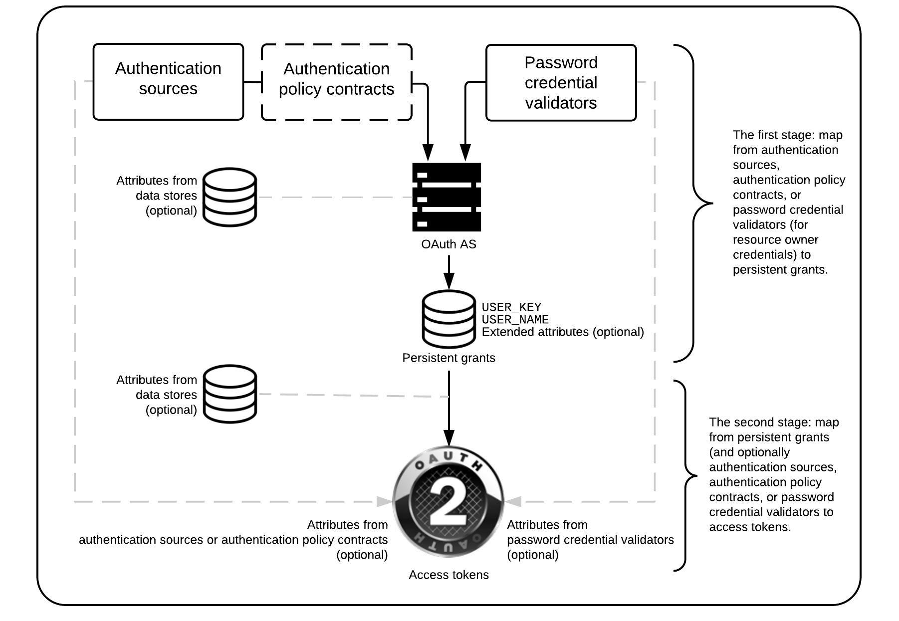
The overall OAuth processing flow at the AS is as follows:
The AS receives an OAuth authorization request from an unauthenticated user.
The AS authenticates the user through the configured authentication adapters, IdP connections, and/or authentication policies.
Information from adapters or policy contracts, optionally combined with user information retrieved from data stores such as Lightweight Directory Access Protocol (LDAP), is used to build a persistent grant context. The two mandatory attributes in the persistent grant context are:
USER_KEY—This is a globally unique user identifier. For ASs that interact with multiple IdPs, this name should be resistant to naming collisions across user organizations (e.g., email address or distinguished name).
USER_NAME—If the user is prompted to authorize the request, this name will be displayed on the page, so a user-friendly name, such as [givenName lastName], could be used here; the name does not need to be unique.
If authorization prompts are enabled, the user is prompted to approve the authorization request; for this lab build, these prompts were disabled on the assumption that fast access to applications is a high priority for the PSFR community.
If the request is authorized, a second mapping process takes place to populate the access token with information from the persistent grant and, optionally, from adapters, policy contracts, or data stores.
Note that persistent grant attributes are stored and can be retrieved and reused when the client uses a refresh token to obtain a new access token, whereas attributes that are looked up in the second stage would be looked up again during the token refresh request. Storing attributes in the persistent grant can therefore reduce the need for repeated directory queries; however, it may be preferable to always query some attributes that are subject to change (like account status) again when a new access token is requested. In addition, it is important to note that storing persistent grant attributes requires a supported relational database or LDAP data store.
The following steps go through the configuration of the AS.
Enable the PingFederate installation to work as an AS. This can be done in the following steps:
Under Main, click the Server Configuration section tab, and then click Server Settings.
In Server Settings, click the Roles & Protocols tab. The Roles & Protocols screen will appear as shown in Figure 3‑2.
Click ENABLE OAUTH 2.0 AUTHORIZATION SERVER (AS) ROLE.
Click ENABLE IDENTITY PROVIDER (IDP) ROLE AND SUPPORT THE FOLLOWING, and then under it, click SAML 2.0. Although this server does not act as a SAML IdP, it is necessary to enable the IdP role and at least one protocol to configure the local user authentication use case.
Click ENABLE SERVICE PROVIDER (SP) ROLE AND SUPPORT THE FOLLOWING, and then under it, click SAML 2.0 and OPENID CONNECT; this enables integration with both types of IdPs.
Figure 3‑2 Server Roles for AS
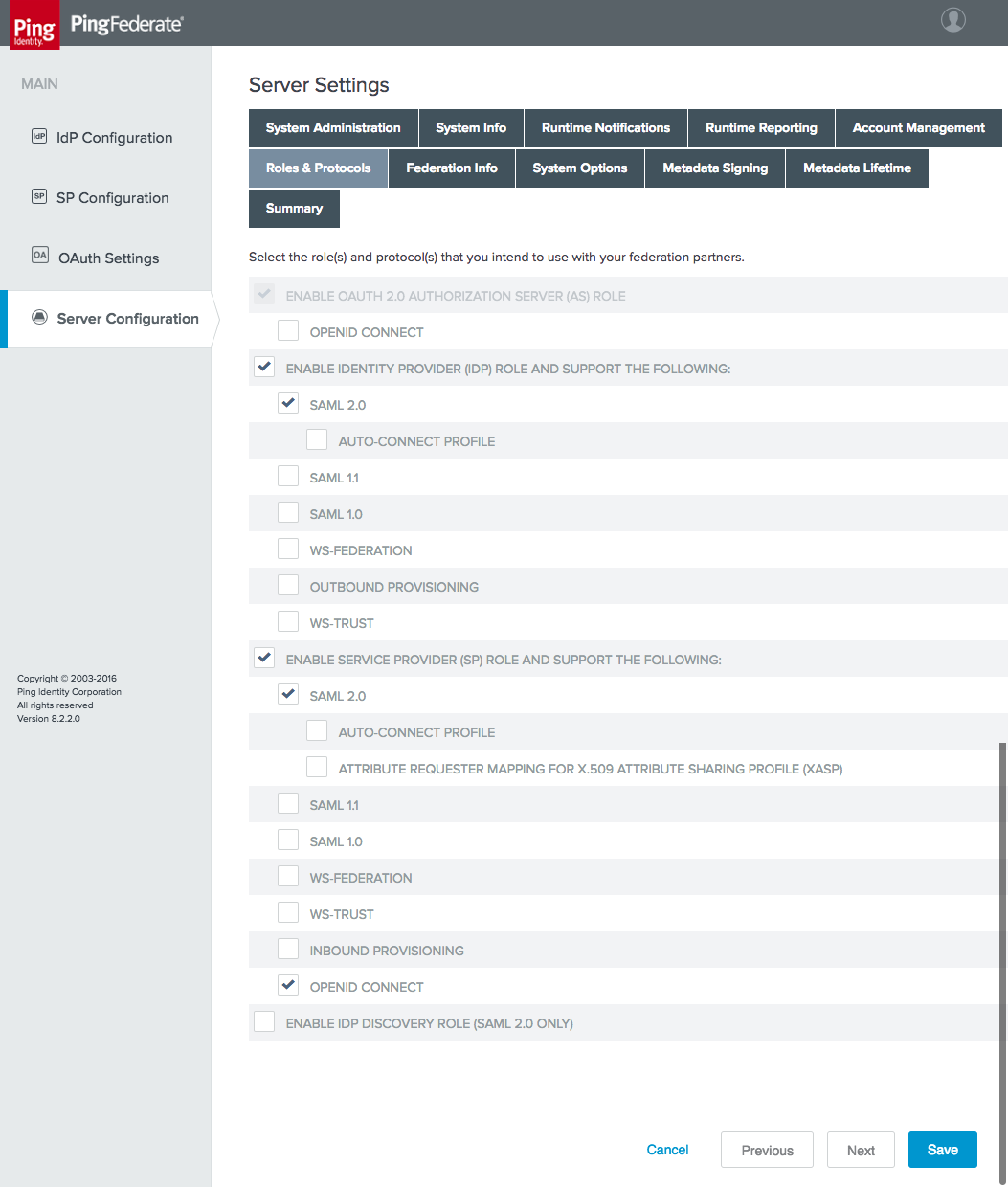
Also under Server Settings, on the Federation Info tab, enter the BASE URL and SAML 2.0 ENTITY ID (Figure 3‑3). The BASE URL should use a public DNS name that is resolvable by any federation partners. The SAML 2.0 ENTITY ID is simply an identifier string that must be unique among federation partners; it is recommended to be a Uniform Resource Identifier (URI), per the SAML 2.0 Core specification [C22].
Figure 3‑3 Federation Info
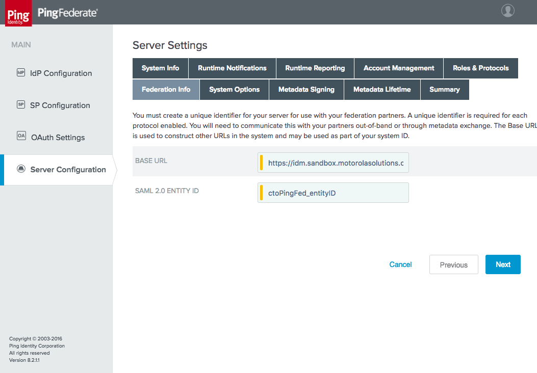
The next step is to configure the OAuth AS. Click the OAuth Settings section tab under Main.
Click Authorization Server Settings under the Authorization Server header. This displays the Authorization Server Settings (Figure 3‑4).
Figure 3‑4 AS Settings
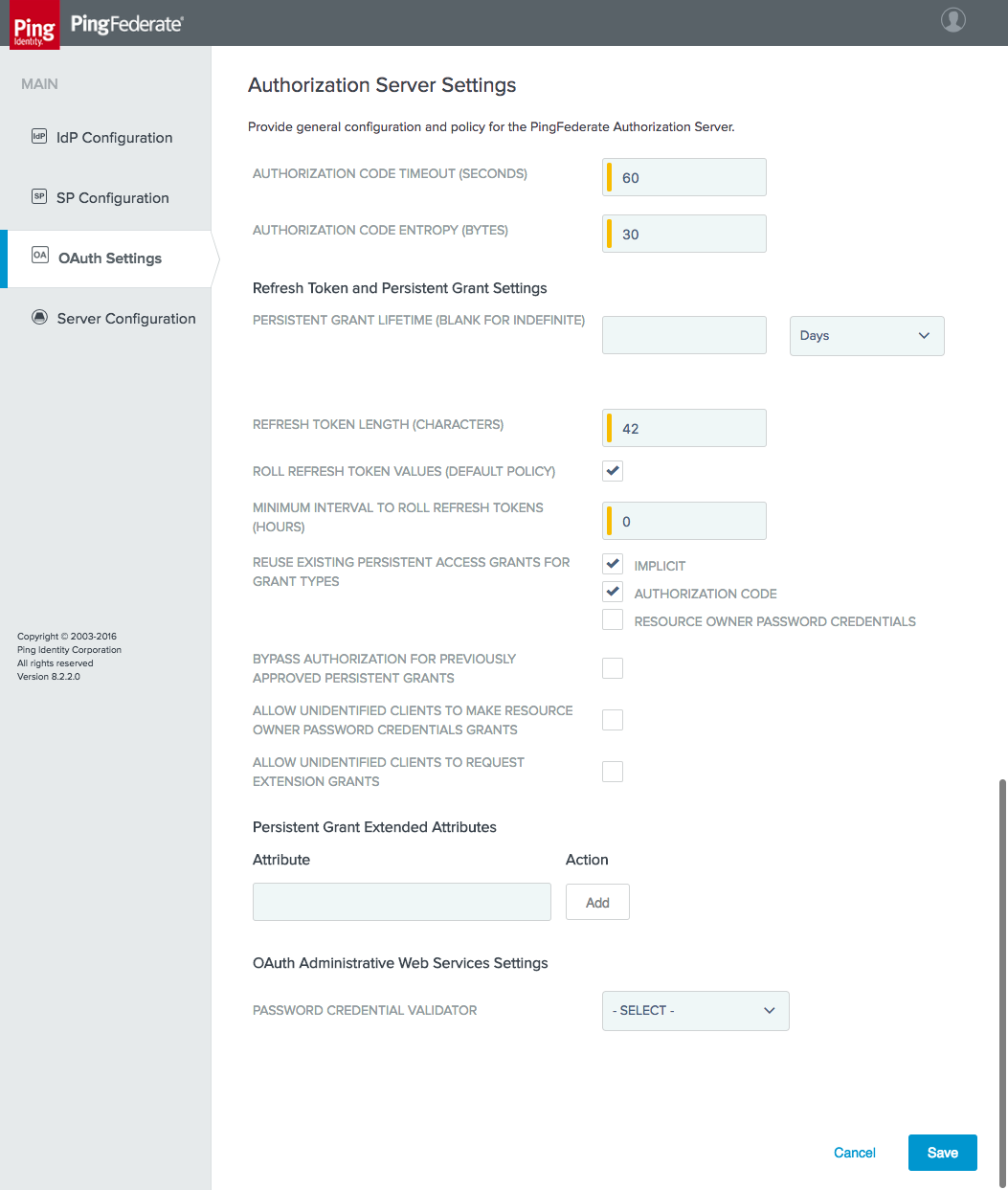
The default settings are suitable for the lab build architecture; organizations may wish to customize these default settings in accordance with organizational security policy or usage requirements. Some notes on individual settings are provided below:
AUTHORIZATION CODE TIMEOUT (SECONDS): Once an authorization code has been returned to a client, it must be exchanged for an access token within this interval. This reduces the risk of an unauthorized client obtaining an access token through brute-force guessing or intercepting a valid client’s code. Proof Key for Code Exchange (PKCE) [C23], as implemented by the AppAuth library, is another useful mechanism to protect the authorization code.
AUTHORIZATION CODE ENTROPY (BYTES): length of the authorization code returned by the AS to the client, in bytes
REFRESH TOKEN LENGTH (CHARACTERS): length of the refresh token, in characters
ROLL REFRESH TOKEN VALUES (DEFAULT POLICY): When selected, the OAuth AS generates a new refresh token value when a new access token is obtained.
MINIMUM INTERVAL TO ROLL REFRESH TOKENS (HOURS): the minimum number of hours that must pass before a new refresh token value can be issued
REUSE EXISTING PERSISTENT ACCESS GRANTS FOR GRANT TYPES:
IMPLICIT: Consent from the user is requested only for the first OAuth resource request associated with the grant.
AUTHORIZATION CODE: Same as above if the BYPASS AUTHORIZATION FOR PREVIOUSLY APPROVED PERSISTENT GRANTS is selected; this can be used to prompt the user for authorization only once to avoid repeated prompts for the same client.
PASSWORD CREDENTIAL VALIDATOR: Required for HTTP Basic authentication if the OAuth Representational State Transfer Web Service is used for managing client applications; this functionality was not used for this build.
Next, configure scopes, as required, for the application. Click the OAuth Settings section tab, and then click Scope Management. The specific scope values will be determined by the client application developer. Generally speaking, scopes refer to different authorizations that can be requested by the client and granted by the user. Access tokens are associated with the scopes for which they are authorized, which can limit the authorities granted to clients. Figure 3‑5 shows several scopes that were added to the AS for this lab build that have specific meanings in the PSX applications suite.
Figure 3‑5 Scopes
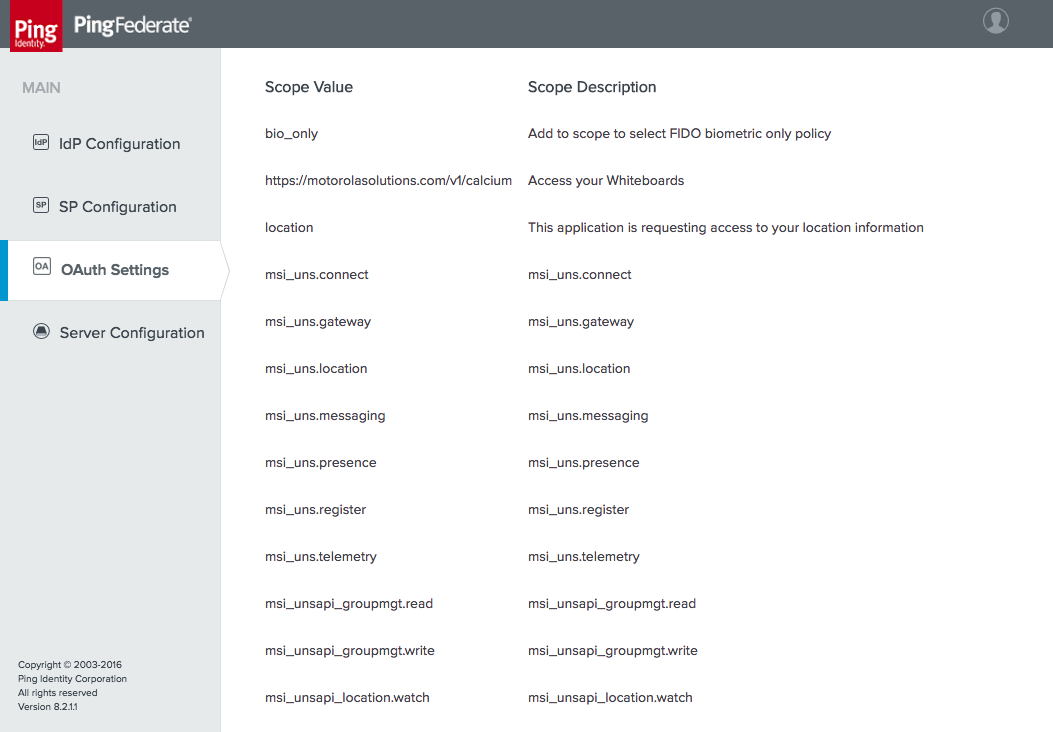
Define an Access Token Management Profile. This profile determines whether access tokens are issued as simple reference token strings or as JWTs. For this lab build, JWTs were used. JWTs are signed and optionally encrypted, so resource servers can validate them locally and they can contain user attributes and other information. Reference tokens are also a viable option, but resource servers must contact the AS’s introspection endpoint to determine whether they are valid and must obtain the granted scopes and any other information associated with them. The Access Token Management Profile also defines any additional attributes that will be associated with the token.
Create an Access Token Manager by following these steps:
Click the OAuth Settings section tab, click Access Token Management, and then click Create New Instance.
On the Type tab, give the instance a meaningful name and ID, and select the token type (Figure 3‑6).
Figure 3‑6 Access Token Management Instance
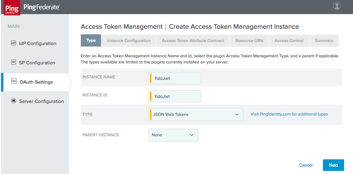
On the next tab, Instance Configuration, select a symmetric key or certificate to use for JWT signing (Figure 3‑7). In this instance, a signing certificate was created as described in Section 3.2.4. Tokens can also optionally be encrypted using JSON Web Encryption (JWE) [C24]; in this case, the client developer would provide a certificate in order to receive encrypted messages. JWE was not used in the lab build.
Figure 3‑7 Access Token Manager Instance Configuration
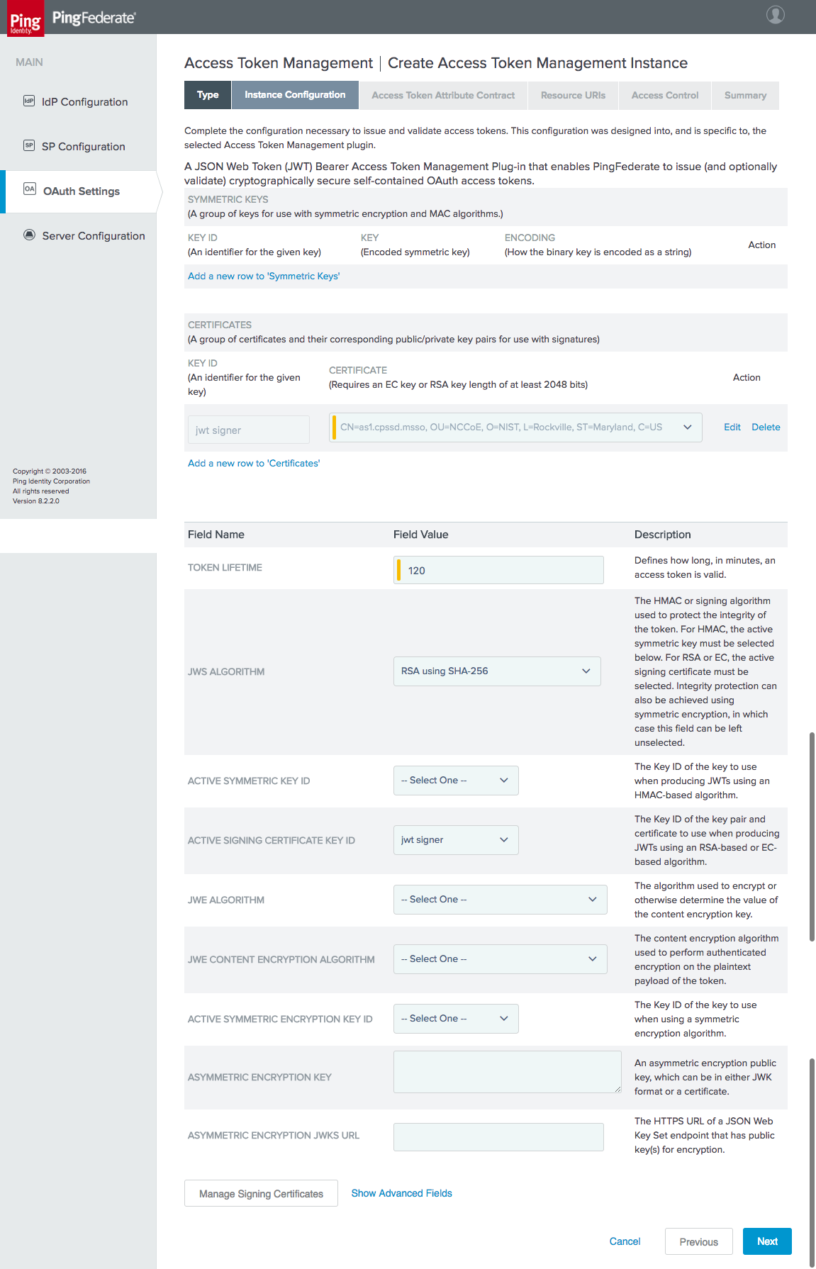
On the Access Token Attribute Contract tab, add the two values realm and sub to the attribute contract (Figure 3‑8).
Figure 3‑8 Access Token Manager Attribute Contract
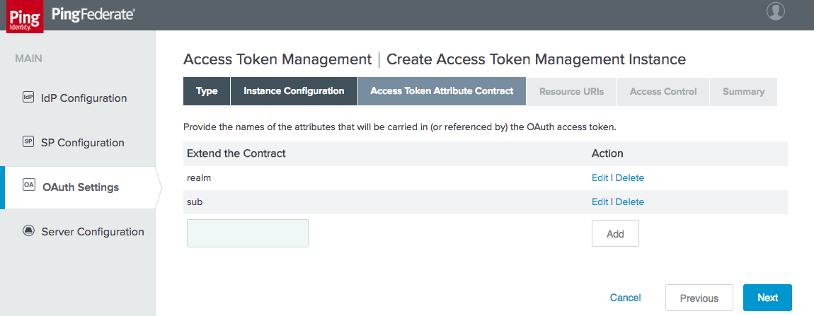
The Resource URIs and Access Control tabs were not used for this build. Click Save to complete the Access Token Manager.
Next, one or more OAuth clients need to be registered with the AS. In the Motorola Solutions use case, the PSX Cockpit application is registered as a client. OAuth Client registration is described for PingFederate at: https://documentation.pingidentity.com/pingfederate/pf82/index.shtml#concept_configuringClient.html.
To create a new client, click the OAuth Settings section tab, click Clients, and then click Create New. Clients are displayed on the rightmost side of the screen in the OAuth Settings window. Once Create New is clicked, the screen shown in Figure 3‑9 and Figure 3‑10 will appear. Due to the vertical size of the pages of this document, the screenshot is divided into two parts for legibility.
Figure 3‑9 OAuth Client Registration, Part 1
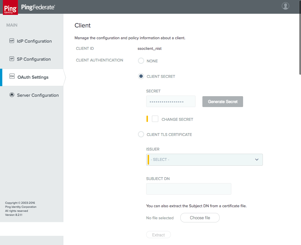
Figure 3‑10 OAuth Client Registration, Part 2
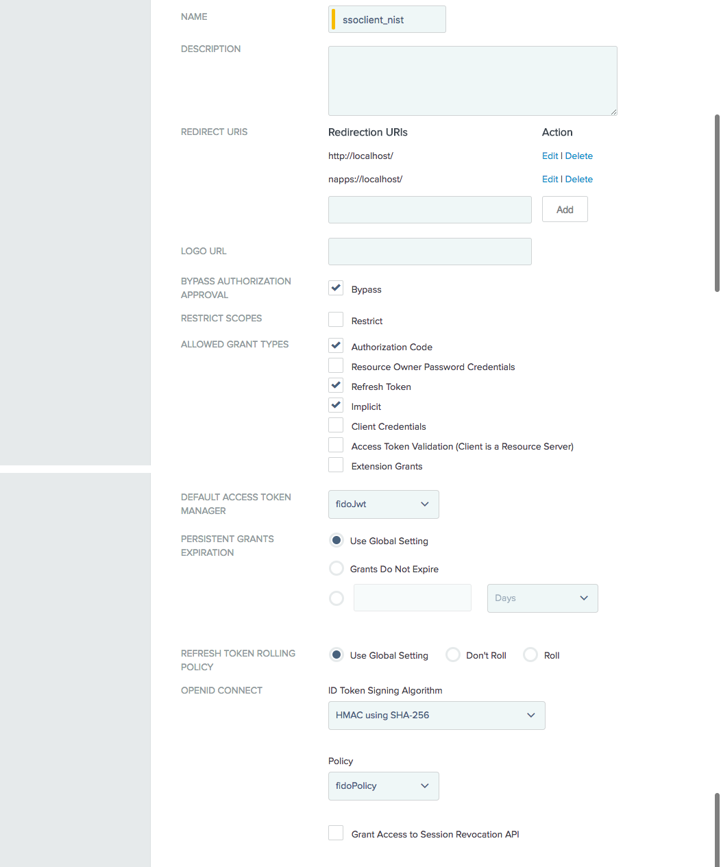
The following are notes on the parameters on this screen:
CLIENT ID: This is a required parameter. This is the unique identifier accompanied with each request that is presented to the AS’s token and authorization endpoints. For this lab build, Motorola Solutions assigned a client ID of “ssoclient_nist” for the instances of their applications on the test devices.
CLIENT AUTHENTICATION: This may be set to NONE, CLIENT SECRET (for HTTP basic authentication), or CLIENT TLS CERTIFICATE. For native mobile application clients, there is no way to protect a client secret or private key and provide it to all instances of the application with any guarantee of confidentiality, as a user might be able to reverse‑engineer the application to obtain any secrets delivered with it, or to debug the application to capture any secrets delivered at runtime. Therefore, a value of NONE is acceptable for native mobile applications, when mitigated with the use of PKCE. For web clients, servers are capable of protecting secrets; therefore, some form of client authentication should be required.
REDIRECT URIS: Redirect URIs are the URIs to which the OAuth AS may redirect the resource owner’s user-agent after authorization is obtained. A redirect URI is used with the Authorization Code and Implicit grant types. This value is typically provided by the application developer to the AS administrator.
ALLOWED GRANT TYPES: These are the allowed grant types for the client. For this lab build, the Authorization Code grant type was used exclusively.
DEFAULT ACCESS TOKEN MANAGER: This is the Access Token Manager profile to be used for this client.
PERSISTENT GRANTS EXPIRATION: This setting offers the option to override the global AS persistent grants settings for this client.
REFRESH TOKEN ROLLING POLICY: This setting offers the option to override the global AS token rolling policy settings for this client.
Once these values are set, click Save to store the client.
This completes the required configuration for the AS’s interactions with OAuth clients. The following section outlines the steps to set up the AS to authenticate users.
3.4 How to Configure the OAuth 2 AS for Authentication
In this section, the AS is configured to authenticate users locally or through federation with a SAML or OIDC IdP. These settings depend on the selection of roles and protocols, as shown in Figure 3‑2; therefore, ensure that has been completed before proceeding.
3.4.1 How to Configure Direct Authentication
The AS was configured to authenticate users with FIDO UAF authentication. This depends on the NNAS, Nok Nok Labs Gateway, and Nok Nok Labs UAF Plugin for PingFederate. See Section 5 for the installation and configuration instructions for those components. This section assumes that those components have already been installed and configured.
3.4.1.1 Configure Adapter Instance
First, an instance of the FIDO UAF adapter must be configured. Click the IdP Configuration section tab, and then click Adapters under Application Integration.
Click Create New Instance to create an IdP adapter instance. This will bring up the new tabbed screen shown in Figure 3‑11.
On the Type tab, the INSTANCE NAME and INSTANCE ID are internal identifiers and can be set to any meaningful values. The TYPE selection, “FIDO Adapter,” will not appear until the Nok Nok Labs UAF plugin has been successfully installed on the PingFederate server as described in Section 5.
Figure 3‑11 Create Adapter Instance
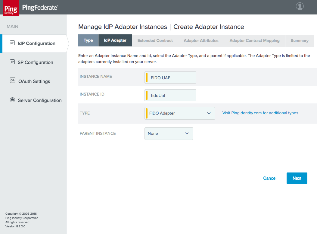
On the IdP Adapter tab, specify the URLs for the Nok Nok Labs API and Gateway endpoints (Figure 3‑12).
The NNL SERVER POLICY NAME field can be used to select a custom policy, if one has been defined on the Nok Nok Labs server; for this build, the default policy was used.
Figure 3‑12 FIDO Adapter Settings
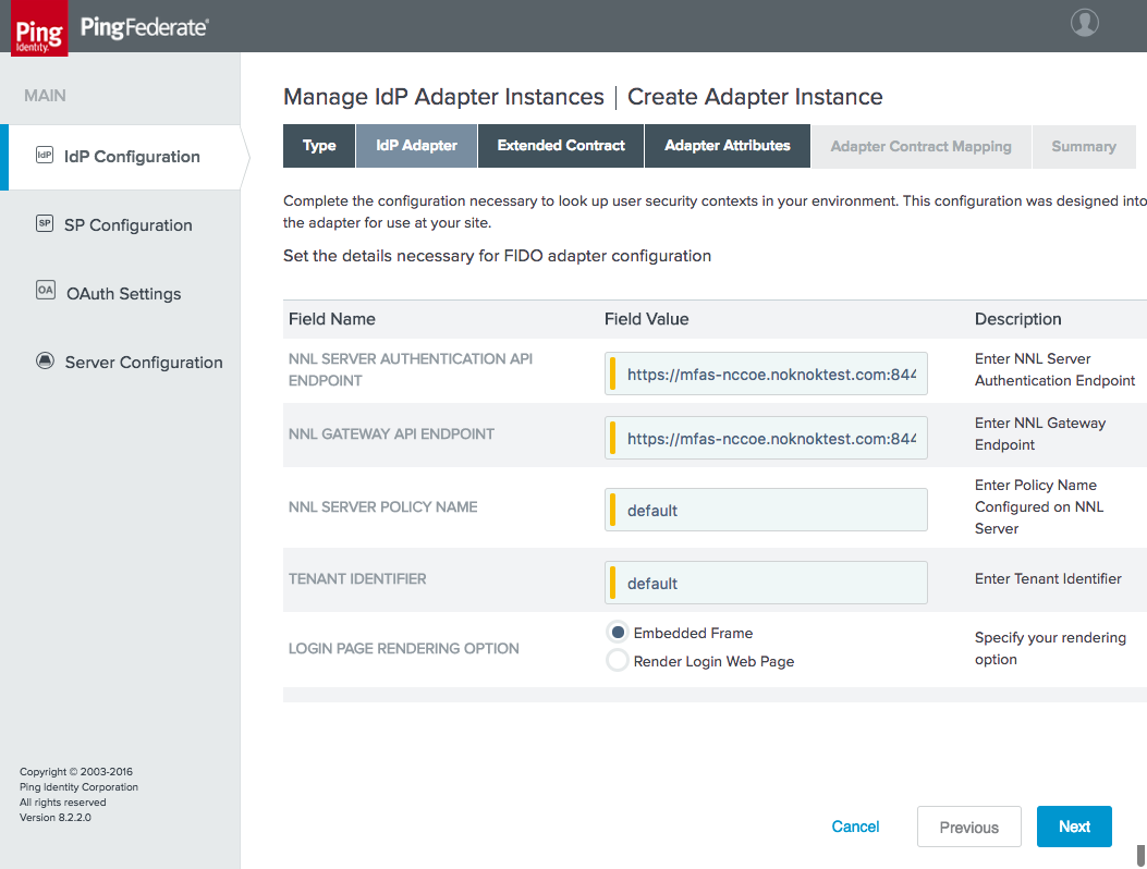
The Extended Contract tab also stayed as the default for the adapter, which provides the riskscore, transactionid, transactiontext, and username values (Figure 3‑13). If desired, additional attributes could be added to the contract and looked up in a user directory, based on the username returned from the adapter.
Figure 3‑13 FIDO Adapter Contract
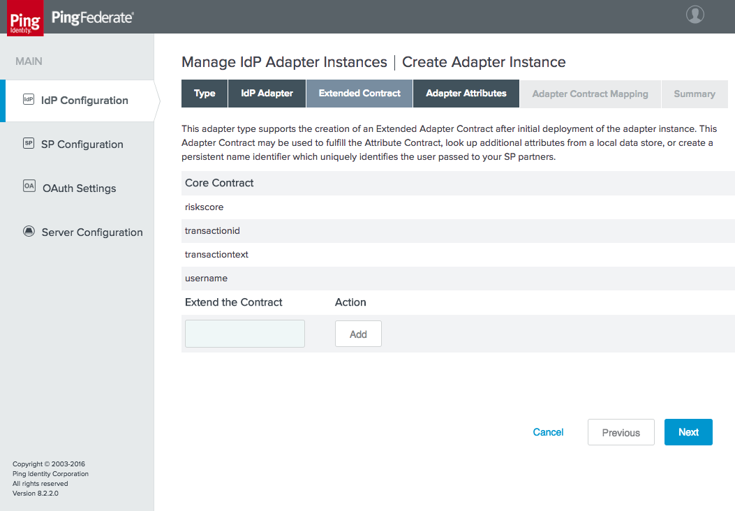
On the Adapter Attributes tab, select the Pseudonym checkbox for username. Pseudonyms were not used in the lab build, but a selection is required on this tab.
There is no need to configure an adapter contract, unless attributes have been added on the Extended Contract tab. Clicking Done and then Save completes the configuration of the adapter. Clicking the adapter name in the list of adapters brings up the Adapter Instance Summary tab, which lists all of the configured settings (Figure 3‑14).
Figure 3‑14 FIDO Adapter Instance Summary
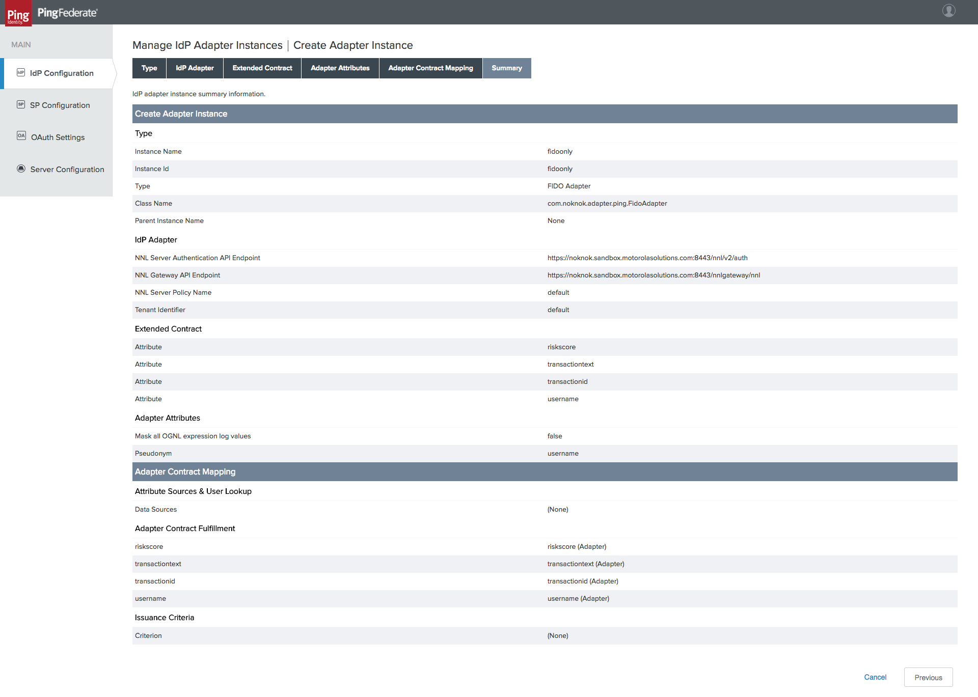
Some additional configurations are needed to tie this authentication adapter to the issuance of an OAuth token. It is possible to directly map the adapter to the access token context, but because the adapter will be incorporated into an authentication policy in this case, an Authentication Policy Contract Mapping is used instead.
3.4.1.2 Create Policy Contract
To create a Policy Contract, navigate to the IdP Configuration section tab, and select Policy Contracts under Authentication Policies. A policy contract defines the set of attributes that will be provided by an authentication policy.
Click Create New Contract.
On the Contract Info tab, give the contract a meaningful name (Figure 3‑15).
Figure 3‑15 Policy Contract Information
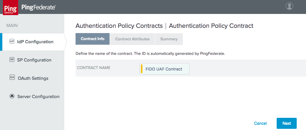
On the Contract Attributes tab, add a value called username (Figure 3‑16).
Figure 3‑16 Policy Contract Attributes
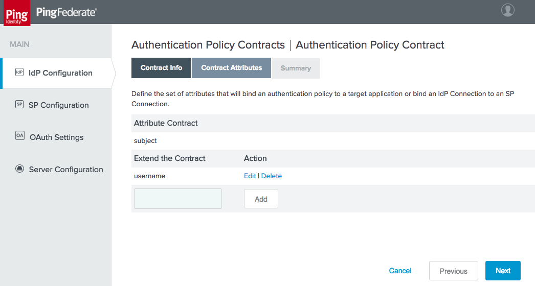
Click Done, and then click Save to save the new contract.
3.4.1.3 Create Policy Contract Mapping
Create a mapping from the policy contract to the OAuth persistent grant. Click the OAuth Settings section tab, and then click Authentication Policy Contract Mapping under Token & Attribute Mapping.
Select the newly created policy contract, and then click Add Mapping (Figure 3‑17).
Figure 3‑17 Create Authentication Policy Contract Mapping
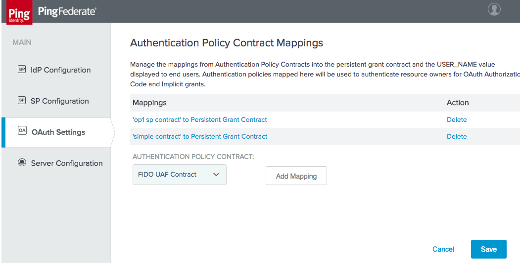
An attribute source could be added at this point to look up additional user attributes, but this is not necessary. Click Save.
Skip the Attribute Sources & User Lookup tab.
On the Contract Fulfillment tab, map both USER_KEY and USER_NAME to the subject value returned from the policy contract (Figure 3‑18).
Figure 3‑18 Authentication Policy Contract Fulfillment
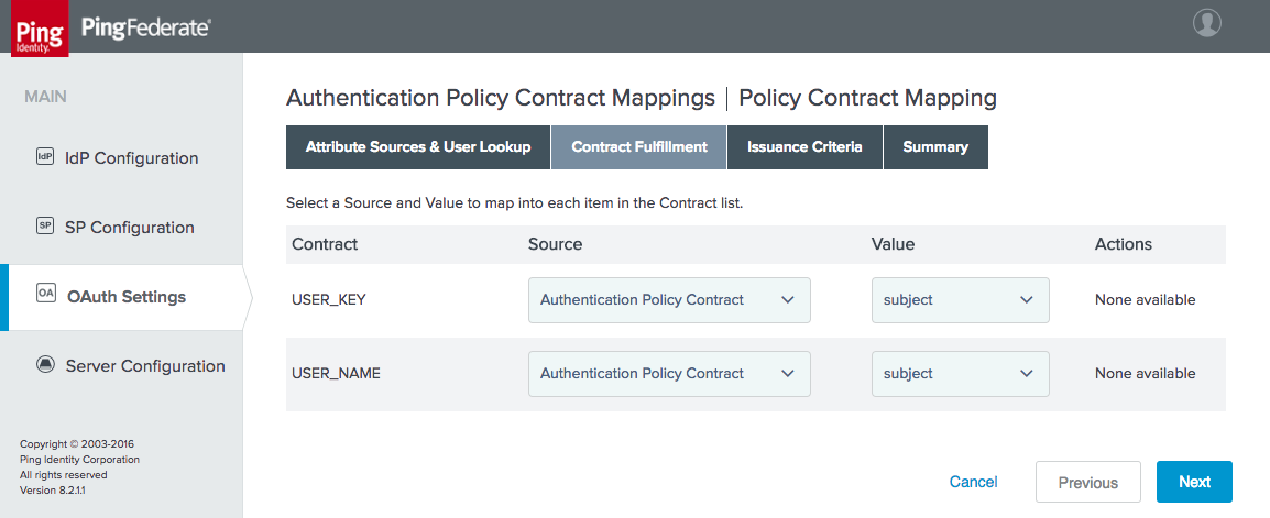
No issuance criteria were specified. Click Next, and then click Save to complete the mapping.
3.4.1.4 Create Access Token Mapping
Finally, an access token mapping needs to be created. In this simple case, the adapter only provides a single attribute (username) and it is stored in the persistent grant, so a default attribute mapping can be used.
On the OAuth Settings section tab, under Token & Attribute Mapping, click Access Token Mapping.
Select Default for the CONTEXT (Figure 3‑19).
Select the ACCESS TOKEN MANAGER created previously (Figure 3‑19).
Figure 3‑19 Create Access Token Attribute Mapping
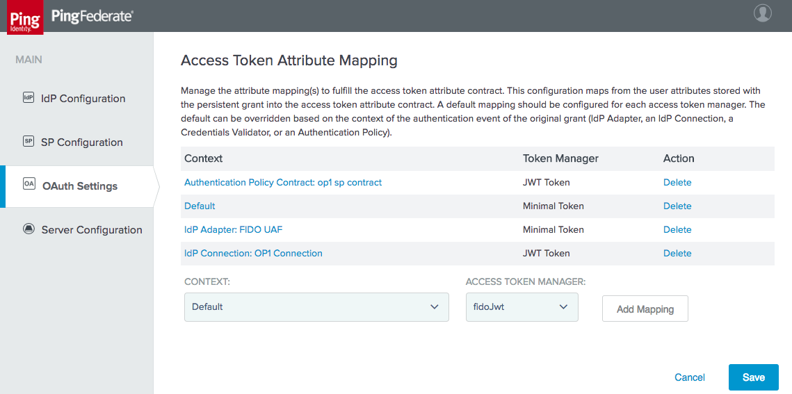
Click Add Mapping.
Click Next to skip the Attribute Sources & User Lookup tab.
On the Contract Fulfillment tab, configure sources and values for the realm and sub contracts (Figure 3‑20). In this case, realm is set to the text string motorolasolutions.com. Click Next.
Figure 3‑20 Access Token Mapping Contract Fulfillment
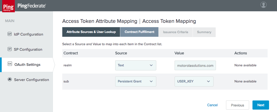
Click Next through the Issuance Criteria tab, and then click Save.
To complete the setup for direct authentication, the FIDO UAF adapter needs to be included in an authentication policy as described in Section 3.4.4.2.
3.4.2 How to Configure SAML Authentication
This section explains how to configure the AS to accept SAML authentication assertions from a SAML 2.0 IdP. This configuration is for RP-initiated SAML web browser SSO, where the authentication flow begins at the AS and the user is redirected to the IdP. Here, it is assumed that all of the steps outlined in Section 3.4 have been completed, particularly enabling the SP role and protocols.
3.4.2.1 Create IdP Connection
Establishing the relationship between the AS and IdP requires coordination between the administrators of the two servers, which will typically belong to two separate organizations. The administrators of the SAML IdP and RP will need to exchange their BASE URL and SAML 2.0 ENTITY ID values (available on the Federation Info tab under Server Settings) to complete the configuration. The IdP administrator must also provide the signing certificate of the IdP. If assertions will be encrypted, the AS administrator will need to provide the IdP administrator with the certificate to be used for the public key. Alternatively, administrators can export their SAML metadata and provide it to the other party to automate parts of the setup.
On the SP Configuration section tab, click Create New under IdP Connections.
On the Connection Type tab, select BROWSER SSO PROFILES, and choose SAML 2.0 for the PROTOCOL (Figure 3‑21). If these options are not present, ensure that the roles are selected correctly in Server Settings.
Figure 3‑21 Create IdP Connection
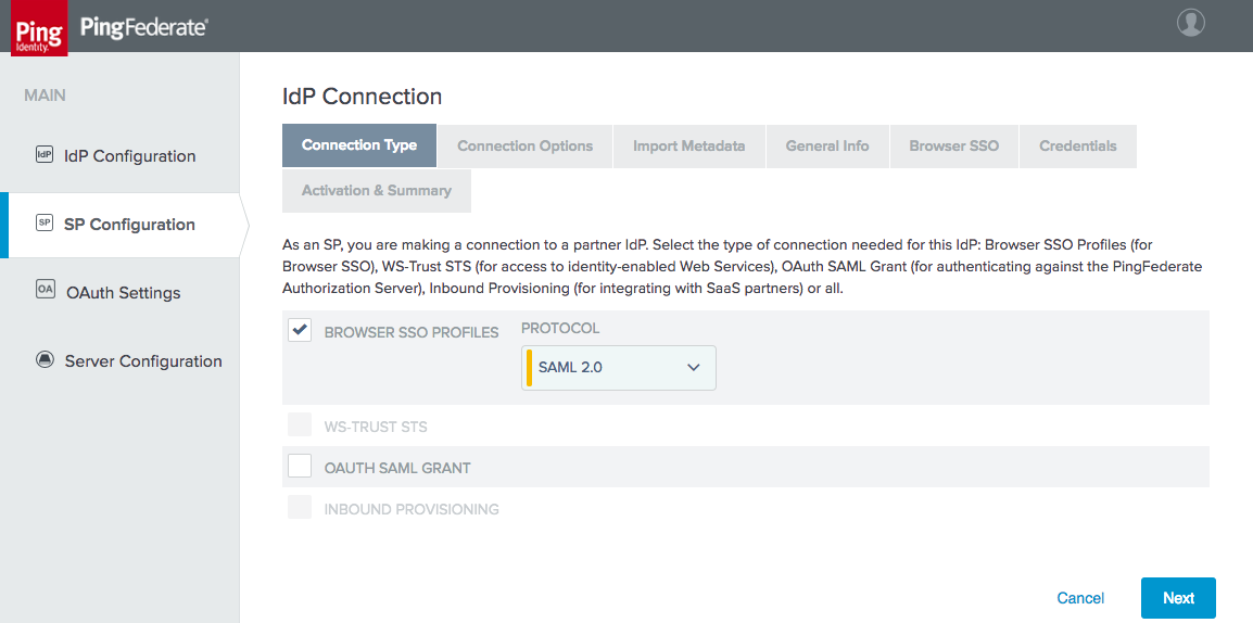
On the Connection Options tab, select BROWSER SSO, and then under it, OAUTH ATTRIBUTE MAPPING (Figure 3‑22).
Figure 3‑22 IdP Connection Options
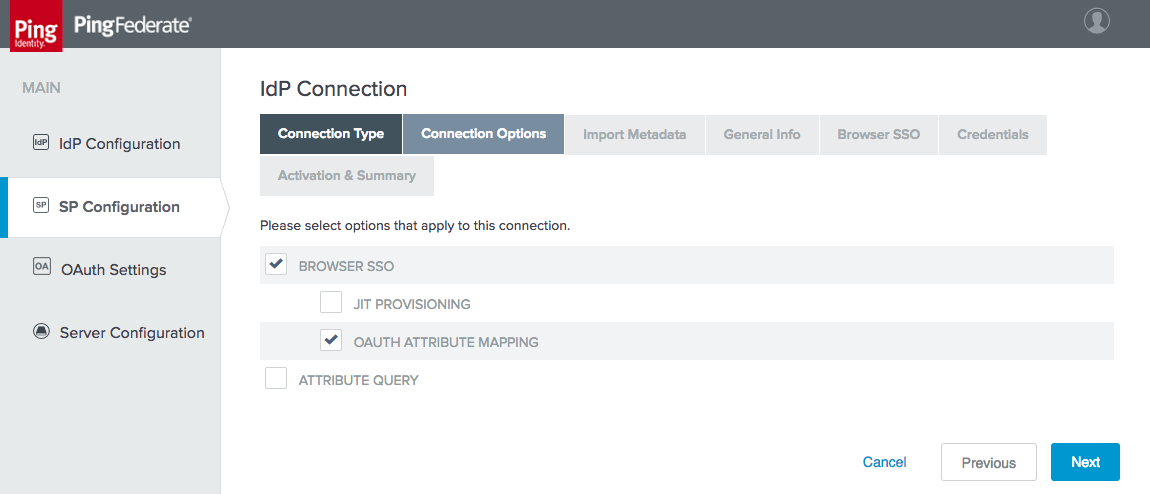
Metadata import was not configured for the lab build; therefore, skip the Import Metadata tab.
On the General Info tab, enter the PARTNER’S ENTITY ID (CONNECTION ID) and BASE URL of the IdP, and provide a CONNECTION NAME (Figure 3‑23).
Figure 3‑23 IdP Connection General Info
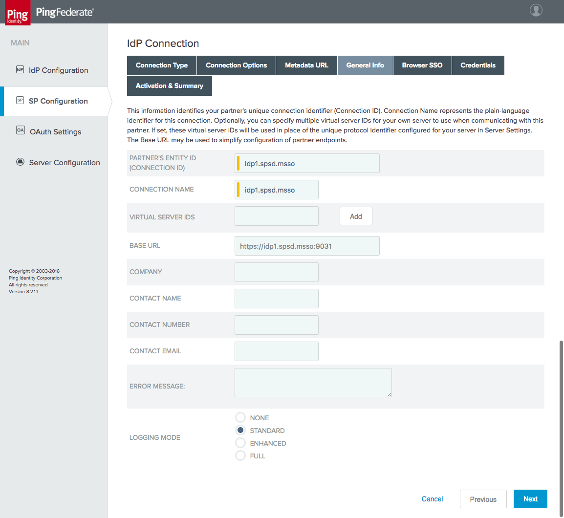
On the Browser SSO tab, click Configure Browser SSO. The Browser SSO setup has multiple sub-pages.
On the SAML Profiles tab, select SP-Initiated SSO. The User‑Session Creation settings are summarized on the Summary tab; they extract the user ID and email address from the SAML assertion (Figure 3‑24).
Figure 3‑24 IdP Connection–User-Session Creation
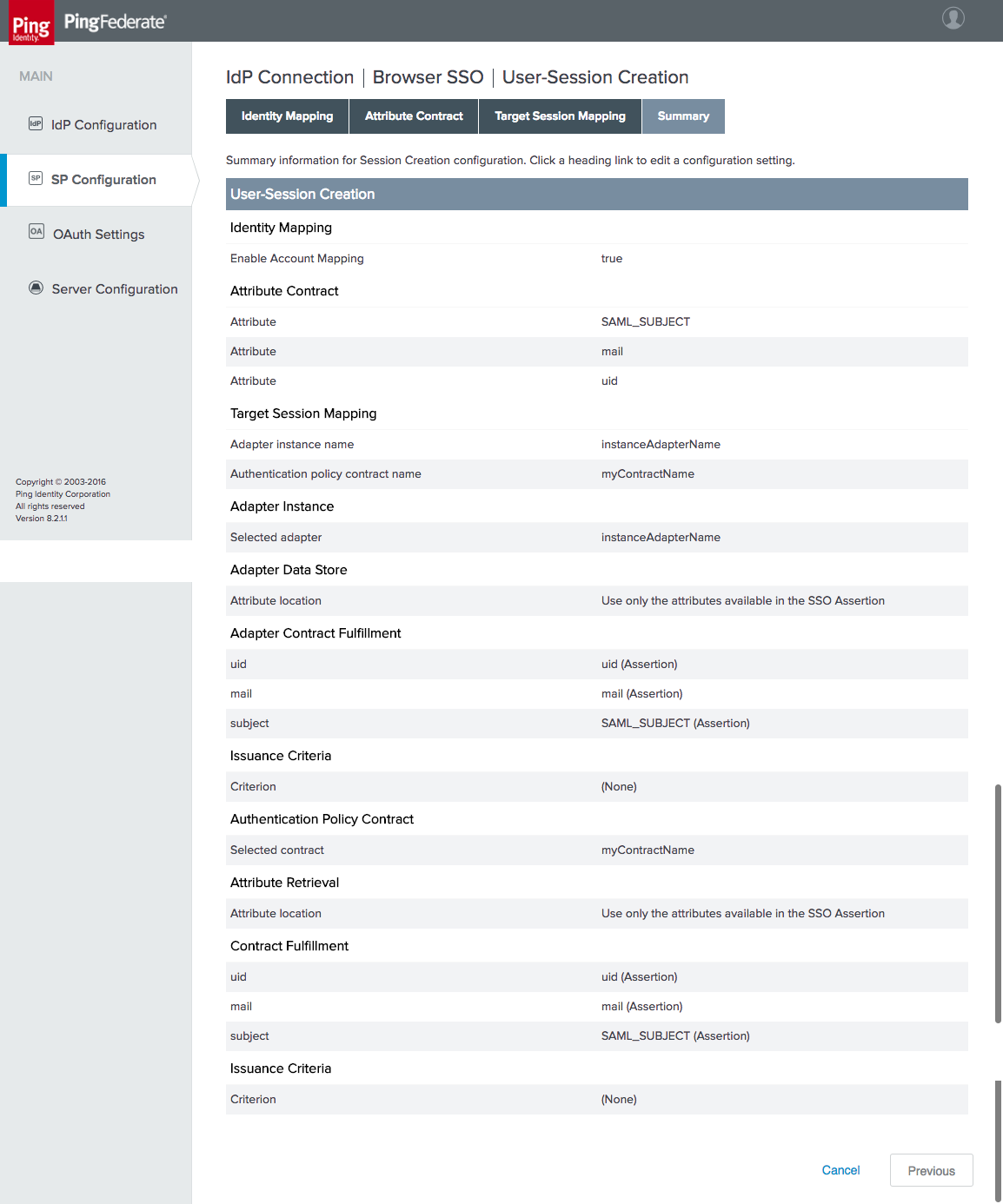
On the OAuth Attribute Mapping Configuration tab, select MAP DIRECTLY INTO PERSISTENT GRANT. Configure the OAuth attribute mapping as shown in Figure 3‑25. This maps both required values in the persistent grant context to the SAML subject. Click Next, then Next again to skip the Issuance Criteria tab. Click Save.
Figure 3‑25 IdP Connection OAuth Attribute Mapping
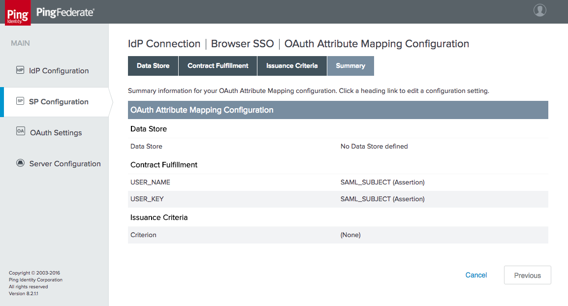
Click Next to proceed to the Protocol Settings tab. The Protocol Settings configure specifics of the SAML protocol, such as the allowed bindings. Configure these as shown in Figure 3‑26. When finished, click Save, which will return you to the Browser SSO tab of the IdP Connection settings.
Figure 3‑26 IdP Connection—Protocol Settings
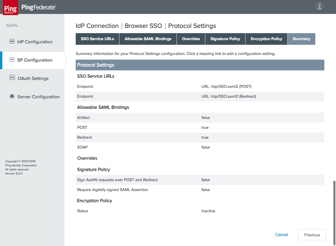
Click Next. On the Credentials tab, the IdP’s signing certificate can be uploaded. This is not necessary if the certificate is signed by a trusted CA.
3.4.2.2 Create Policy Contract
Create a policy contract as described in Section 3.4.1.2, with the attributes subject, mail, and uid (Figure 3‑27).
Figure 3‑27 Policy Contract for SAML RP
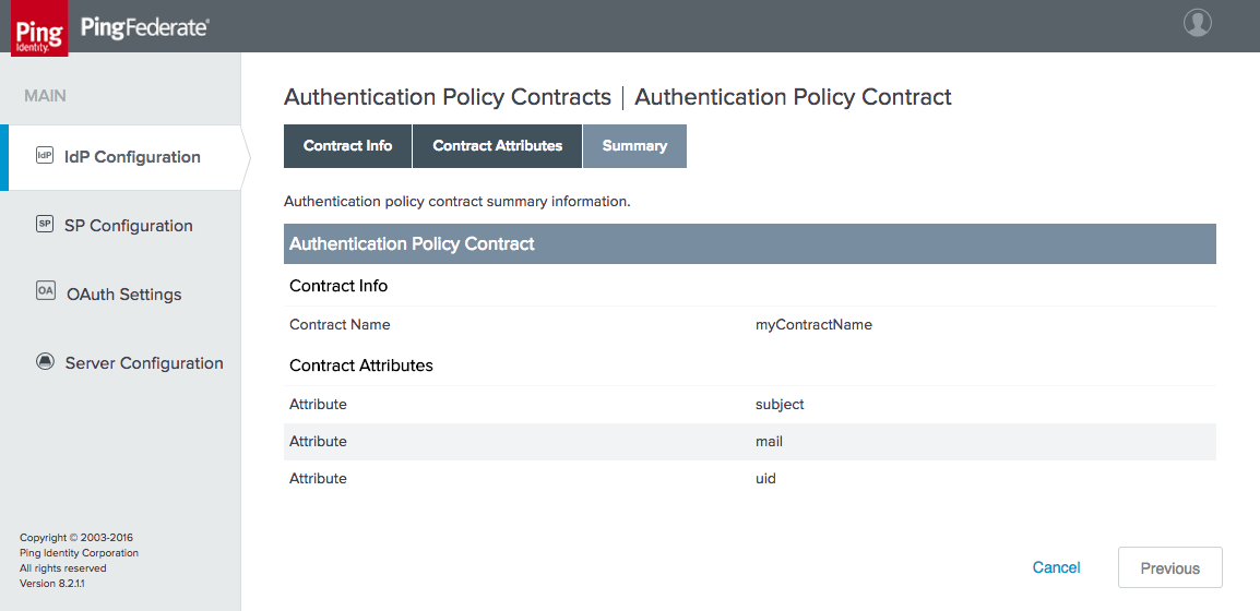
3.4.2.3 Create Policy Contract Mapping
Create an OAuth policy contract mapping for the newly created policy as described in Section 3.4.1.3, mapping USER_NAME and USER_KEY to subject (Figure 3‑28).
Figure 3‑28 Contract Mapping for SAML RP
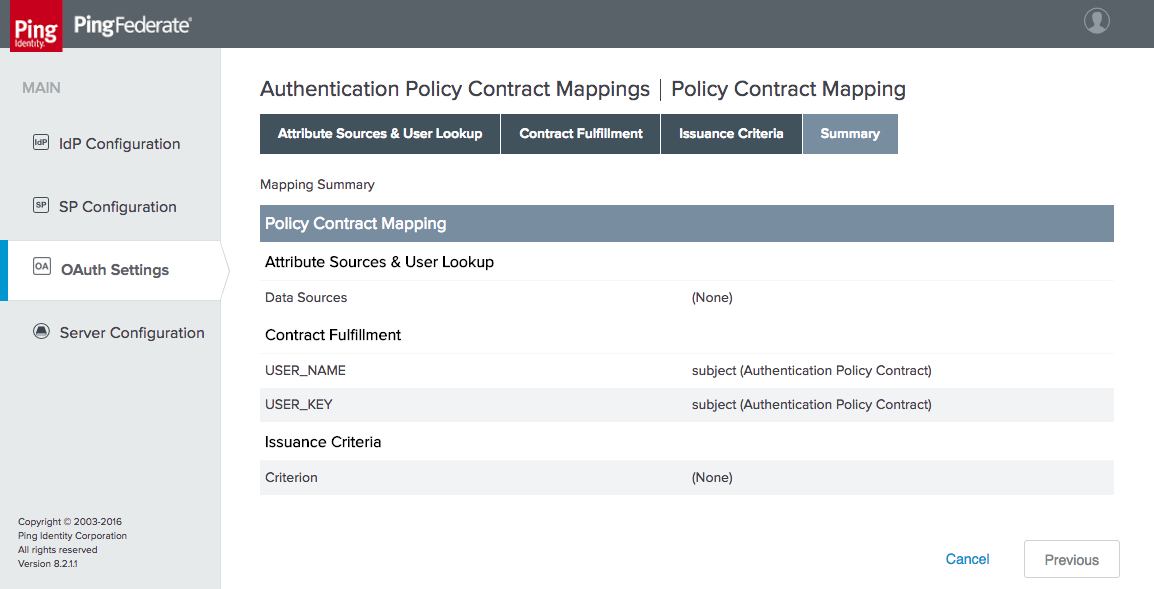
To complete the setup for SAML authentication, kspd.msso adapter needs to be included in an authentication policy as described in Section 3.4.4.2.
3.4.3 How to Configure OIDC Authentication
As with the configuration of a SAML IdP connection, integrating the AS with an OIDC IdP requires coordination between the administrators of the two systems. The administrator of the IdP must create an OIDC client registration before the connection can be configured on the AS side. The AS administrator must provide the redirect URI and, if encryption of the ID Token is desired, a public key. Unlike with SAML, there is no metadata file to exchange; however, if the IdP supports the OIDC discovery endpoint, the client can automatically obtain many of the required configuration settings from the discovery URL.
This section assumes that the AS role and OIDC SP support have been enabled via Server Settings, as described in Section 3.4. This section also uses the same authentication policy contract as the SAML authentication implementation. Create the policy contract as described in Section 3.4.2.2, if it does not already exist.
3.4.3.1 Create IdP Connection
On the SP Configuration section tab, click Create New under IdP Connections.
On the Connection Type tab, select BROWSER SSO PROFILES, and then under it, select OpenID Connect for the PROTOCOL (Figure 3‑29).
Figure 3‑29 IdP Connection Type
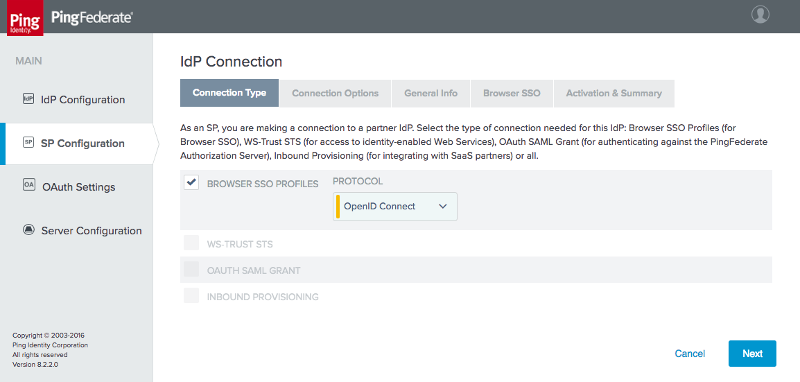
On the Connection Options tab, select BROWSER SSO, and then under it, select OAUTH ATTRIBUTE MAPPING (Figure 3‑30).
Figure 3‑30 IdP Connection Options
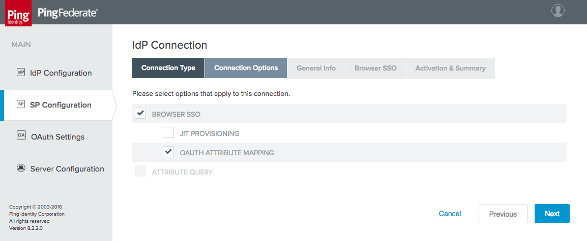
On the General Info tab, enter the ISSUER value for the IdP (Figure 3‑31). This is the BASE URL setting available on the Federation Info tab, under the Server Configuration section tab on the IdP. Then click Load Metadata, which causes the AS to query the IdP’s discovery endpoint. The message “Metadata successfully loaded” should appear. Provide a CONNECTION NAME, and enter the CLIENT ID and CLIENT SECRET provided by the IdP administrator.
Figure 3‑31 IdP Connection General Info
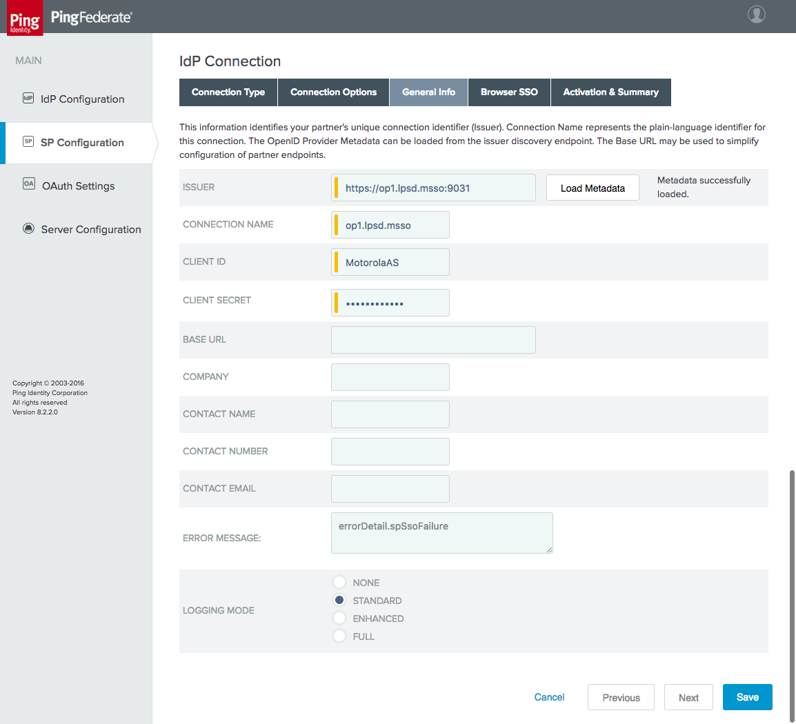
On the Browser SSO tab, click Configure Browser SSO, then click Configure User-Session Creation. The User-Session Creation page will appear.
On the Target Session Mapping tab, click Map New Authentication Policy.
On the Authentication Policy Contract tab, select the AUTHENTICATION POLICY CONTRACT created in Section 3.4.2.2 (in the example shown in Figure 3‑32, it is called myContractName). If the policy contract has not been created, click Manage Authentication Policy Contracts, and create it now.
Figure 3‑32 IdP Connection Authentication Policy Contract
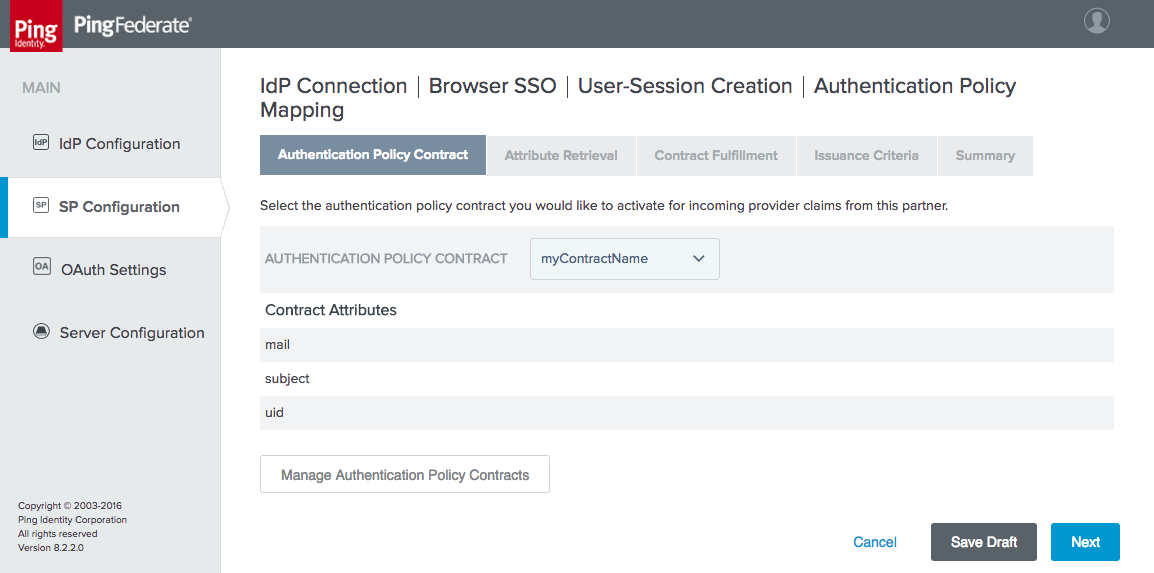
On the Attribute Retrieval tab, leave the default setting (use only the attributes available in the provider claims).
On the Contract Fulfillment tab, map the mail, subject, and uid attributes to the email, sub, and sub provider claims (Figure 3‑33).
Figure 3‑33 IdP Connection Policy Contract Mapping
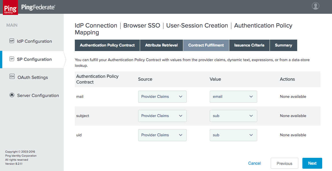
No Issuance Criteria were configured; therefore, skip the Issuance Criteria tab.
Click Next, then Done, and then click Done again to exit the User-Session Creation tab.
On the OAuth Attribute Mapping Configuration tab, select Map Directly into Persistent Grant, and then click Configure OAuth Attribute Mapping.
Click Next to skip the Data Store tab. On the Contract Fulfillment tab, map both USER_NAME and USER_KEY to the sub provider claim (Figure 3‑34).
Figure 3‑34 IdP Connection OAuth Attribute Mapping
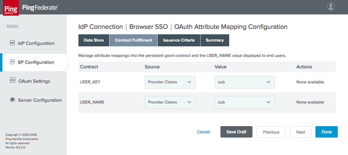
Click Done to exit the OAuth Attribute Mapping Configuration setup. The Protocol Settings should be automatically populated through the information gathered from the discovery endpoint (Figure 3‑35). If necessary, the scopes to be requested can be customized on the Protocol Settings tab; in the lab, these settings remained at the default.
Figure 3‑35 IdP Connection Protocol Settings
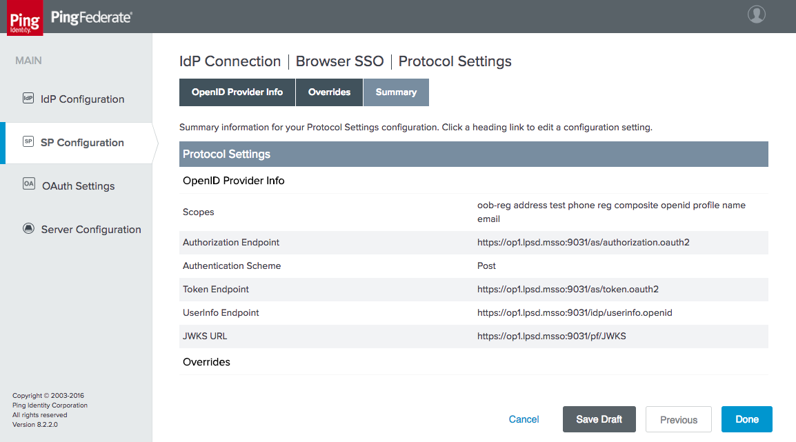
Click Done to exit the Browser SSO configuration setup.
On the Activation & Summary tab, a Redirect URI will be generated (Figure 3‑36). Provide this information to the IdP administrator, as it needs to be configured in the OpenID Client settings on the IdP side.
The Connection Status can also be configured to ACTIVE or INACTIVE on this tab.
Figure 3‑36 IdP Connection Activation and Summary
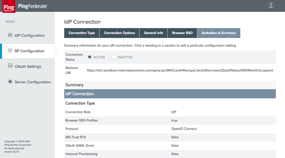
Click Save to complete the IdP Connection setup.
3.4.3.2 Create the Policy Contract Mapping
The same policy contract mapping created earlier for the SAML integration can also be used for OIDC integration, as the attribute names are identical. If this policy contract mapping has not already been created, refer to Section 3.4.2.3 to create it.
3.4.4 How to Configure the Authentication Policy
3.4.4.1 Install the Domain Selector Plugin
When a single AS is integrated with multiple IdPs, it needs a means of determining which IdP can authenticate each user. In the lab build, a domain selector is used to determine whether the AS should authenticate the user locally, redirect to the SAML IdP, or redirect to the OIDC IdP. The domain selector prompts the user to enter the user’s email address or domain. The specified domain is used to select which branch of the authentication policy should be applied. Upon successful authentication, the domain selector sets a cookie in the browser to record the domain selection to avoid prompting the user each time that the user authenticates.
PingFederate includes sample code for a Domain Selector plugin. Before the Domain Selector can be used in an authentication policy, it must be built. The source code for the selector is located under the PingFederate directory, in the directory sdk/plugin-src/authentication-selector-example.
Complete the following steps to build the selector:
Edit the
build.local.propertiesfile in the PingFederate SDK directory to set the target plugin as follows:target-plugin.name=authentication-selector-exampleRun the following commands to build and install the plugin:
$ ant clean-plugin

$ ant jar-plugin

$ ant deploy-plugin

$ sudo service pingfederate restart
Once installed, the Domain Selector can be configured with the required values. On the IdP Configuration section tab, click Selectors under Authentication Policies.
Click Create New Instance.
On the Type tab, provide a meaningful name and ID for the selector instance (Figure 3‑37). For the TYPE, select Domain Authentication Selector.
Figure 3‑37 Authentication Selector Instance
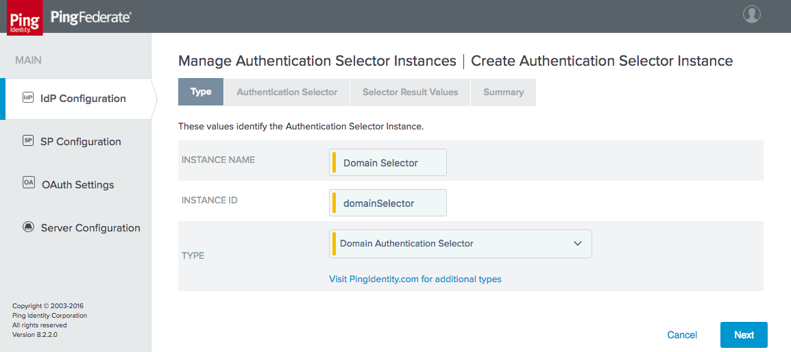
The next tab, Authentication Selector, prompts for the HyperText Markup Language (HTML) template for the page that will prompt the user to enter the domain or email address (Figure 3‑38). The default value will use the template delivered with the adapter; if desired, a custom template can be used instead to modify the appearance of the page. Provide a cookie name, which will be used to persist the domain selection. Finally, the age of the cookie can be modified. By default, users will be prompted again to enter their domain after 30 days.
Figure 3‑38 Authentication Selector Details
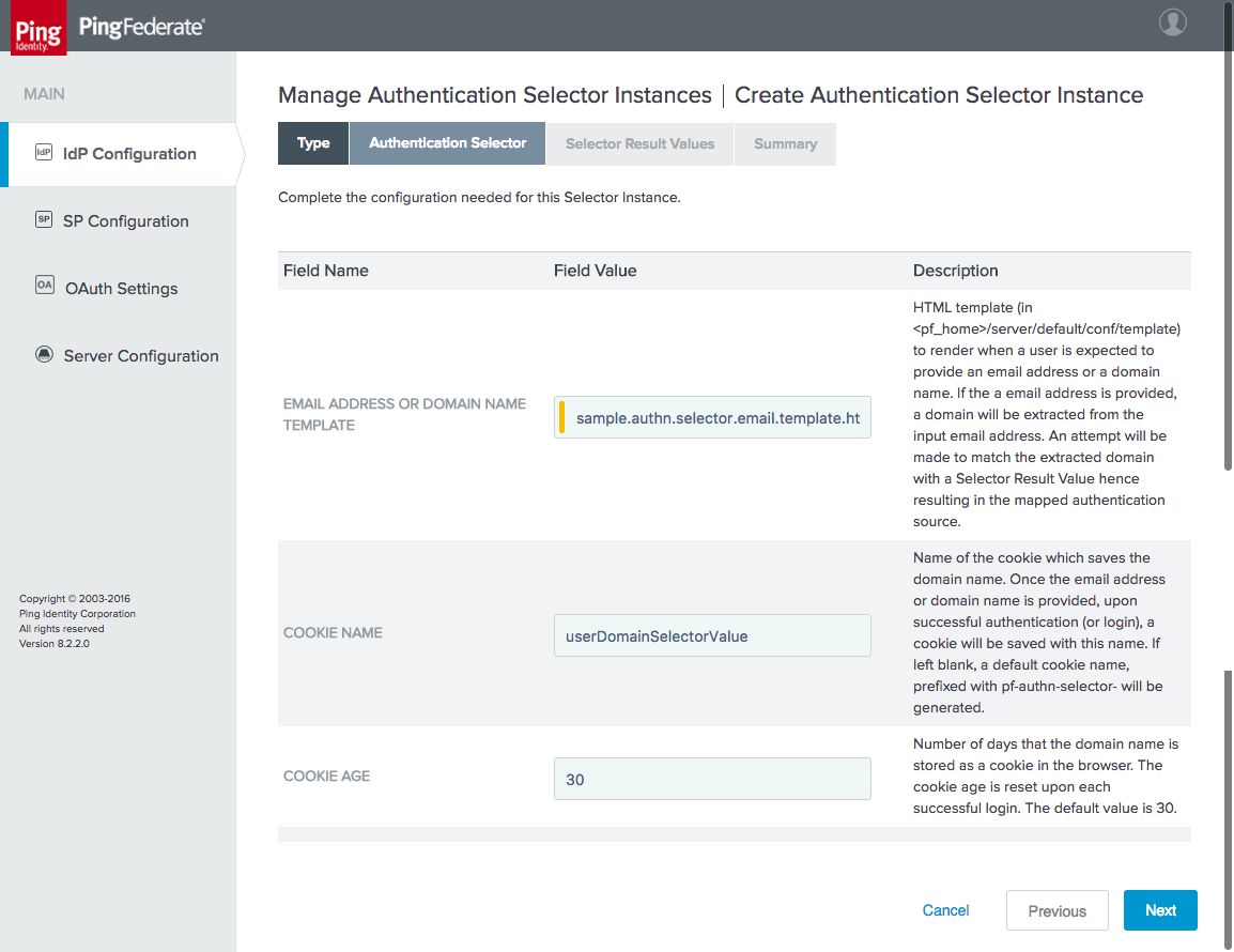
On the Selector Result Values tab, specify the expected domain values (Figure 3‑39). When the domain selector is used in an access policy, different policy branches will be created for each of these values. In this case, if the domain is motorolasolutions.com, the user will be authenticated locally; if it is lpsd.msso or spsd.msso, the user will be redirected to the corresponding IdP to authenticate.
Figure 3‑39 Selector Result Values
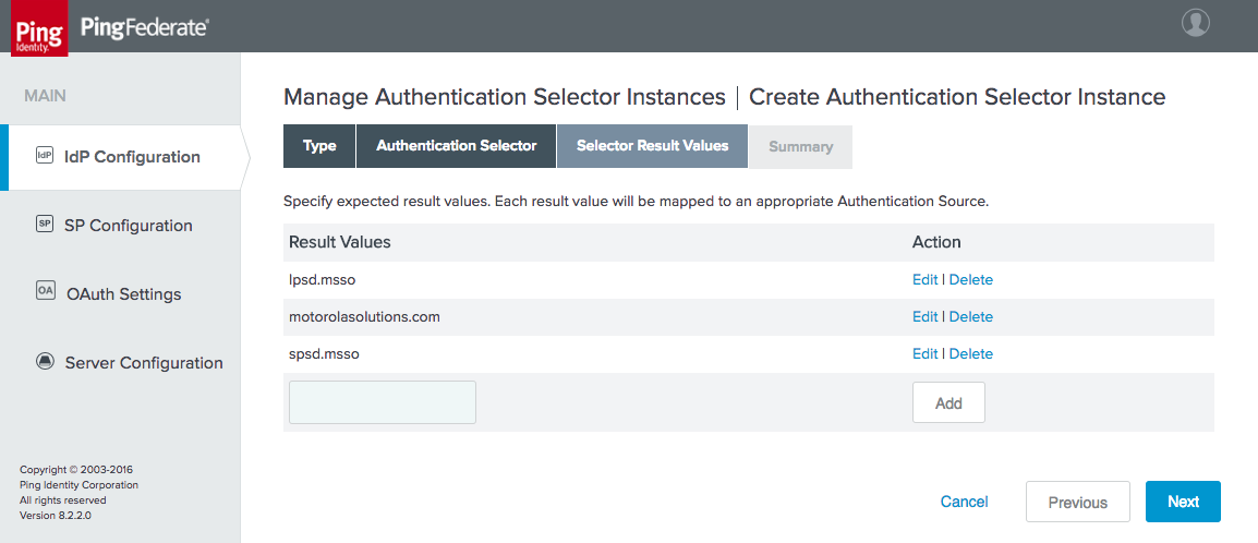
Click Done, and then click Save to complete the selector configuration.
3.4.4.2 Define the Authentication Policy
On the IdP Configuration page, click Policies under Authentication Policies.
Select the three checkboxes at the top of the Manage Authentication Policies page, which are shown in Figure 3‑40.
Figure 3‑40 Policy Settings
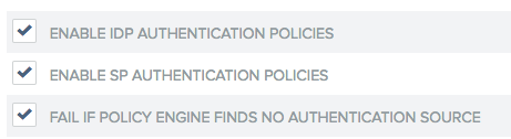
Select the Domain Selector as the first element in the policy (Figure 3‑41). This will create policy branches for the three values defined for the policy selector.
Select the corresponding authentication mechanism for each domain. The example shown in Figure 3‑41 uses the IdP connections for the lpsd.msso and spsd.msso, as well as the “fidoonly” adapter for local authentication of users in the motorolasolutions.com domain.
Figure 3‑41 Authentication Policy
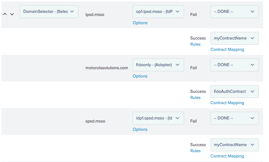
There is no need to specify Options or Success Rules. For the two IdP connections, apply the myContractName policy contract upon success, with the contract mapping configured as shown in Figure 3‑42.
Figure 3‑42 Policy Contract Mapping for IdP Connections
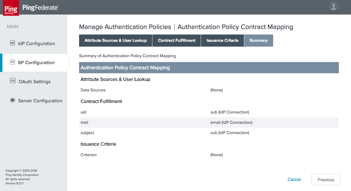
For the “fidoonly” adapter, apply the fidoAuthContract with the contract mapping shown in Figure 3‑43.
Figure 3‑43 Policy Contract Mapping for Local Authentication
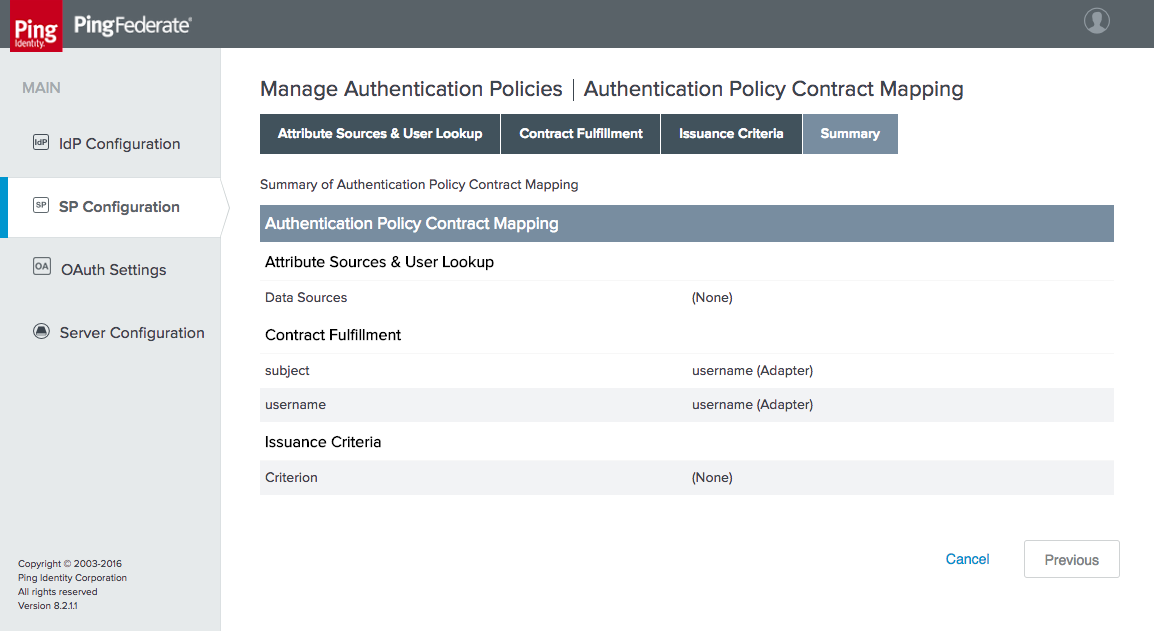
This completes the configuration of the AS.
4 How to Install and Configure the Identity Providers
PingFederate 8.3.2.0 was used for the SAML and OIDC IdP installs. The system requirements and installation process for PingFederate are identical to the OAuth AS installation documentation in Section 3.1 and Section 3.2. The IdP configuration sections pick up the installation process after the software has been installed, at the selection of roles and protocols.
4.1 How to Configure the User Store
Each IdP uses its own AD forest as a user store. AD was chosen due to its widespread use across many organizations. For the purposes of this project, any LDAP directory could have served the same purpose, but in a typical organization, AD would be used for other functions, such as workstation login and authorization to applications, shared drives, printers, and other services. The Active Directory Users and Computers console (Figure 4‑1) was used to create user accounts and set attributes.
Figure 4‑1 Active Directory Users and Computers
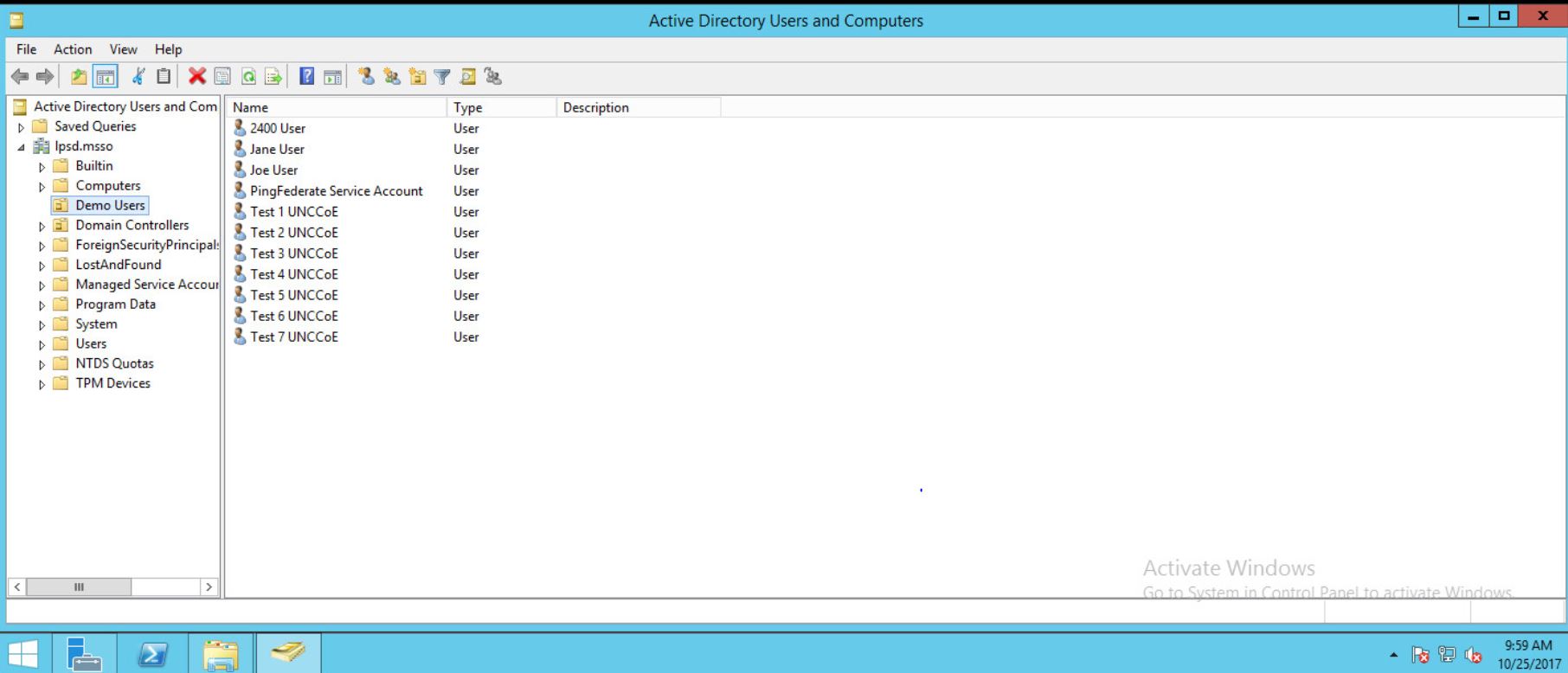
In addition to the user accounts that log in to the lab applications, a service account must be created to enable the IdP to access and query the AD. This user’s LDAP Distinguished Name (DN) and password (in the example shown in Figure 4‑1) are used in the PingFederate directory integration described below.
The procedure for connecting a PingFederate IdP to an LDAP directory is the same for a SAML or OIDC IdP. Documentation is provided at https://documentation.pingidentity.com/pingfederate/pf82/index.shtml#concept_configuringLdapConnection.html.
To start the process, click the Server Configuration section tab on the left side of the PingFederate administrative console. The screen shown in Figure 4‑2 will appear.
Figure 4‑2 Server Configuration
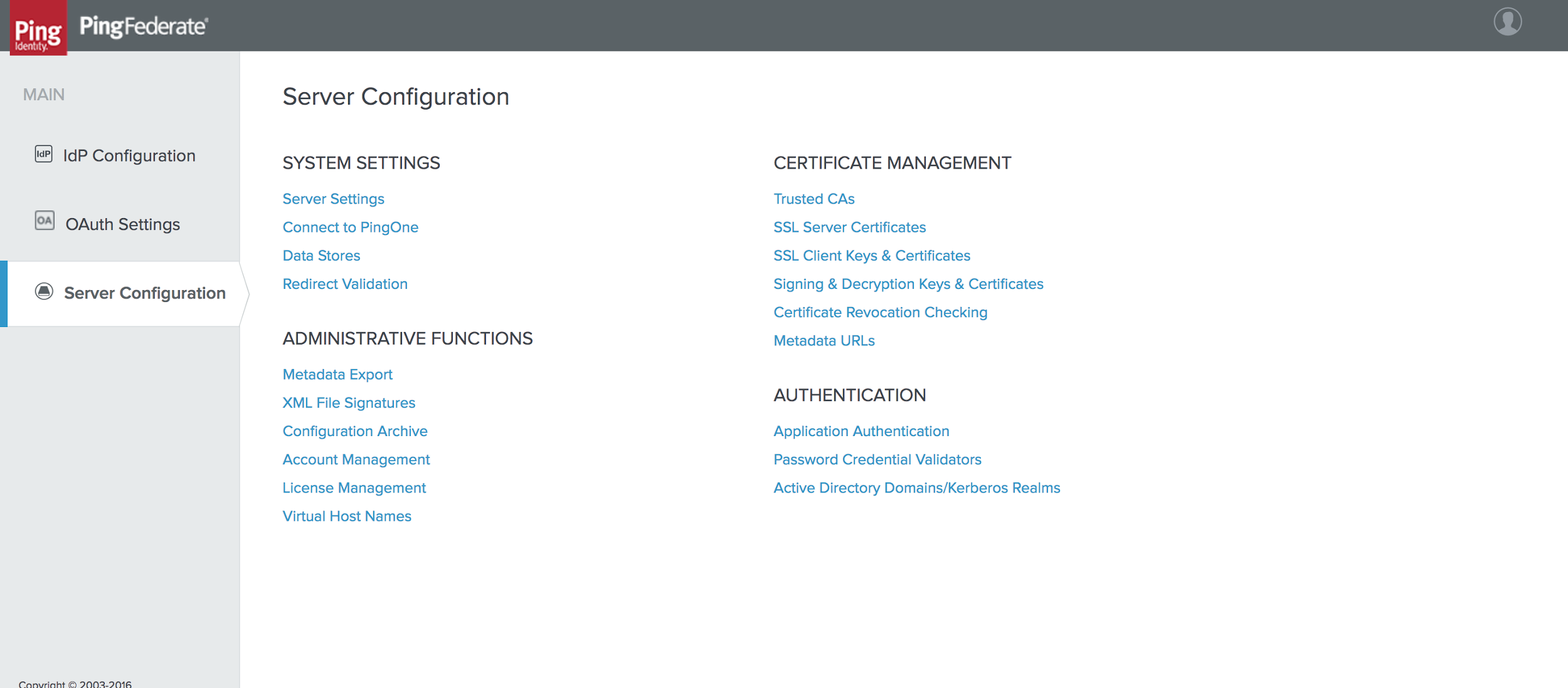
Click Data Stores under SYSTEM SETTINGS.
On the next screen, click Add New Data Store.
The screen shown in Figure 4‑3 will appear. On the Data Store Type tab, select LDAP for the data store type.
Click Next.
Figure 4‑3 Data Store Type
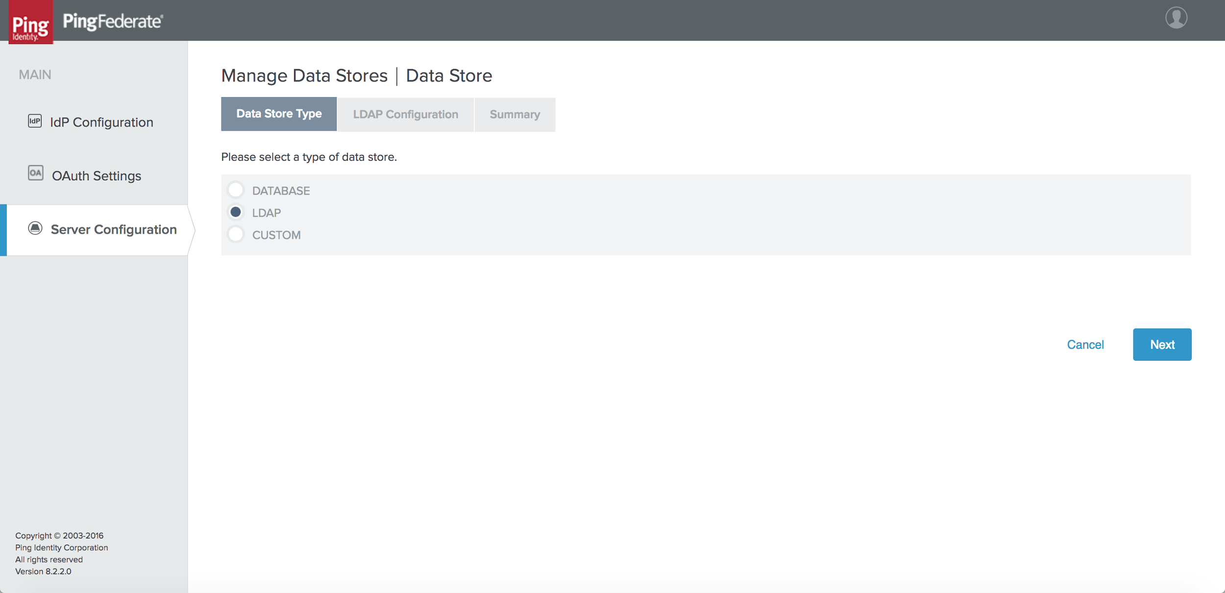
On the LDAP Configuration tab, enter the connection parameters for your AD or LDAP environment (Figure 4‑4). Some notes on the fields on this tab are provided below. Click Save to exit the LDAP configuration screen once the required settings have been entered.
- HOST NAME(S): Enter the Fully Qualified Domain Name (FQDN) or the complete Internet Protocol (IP) address of an AD domain controller. A port number can be specified if AD is running on non-standard ports.
- LDAP TYPE: This is the LDAP server in use—AD in this case.
- BIND ANONYMOUSLY: For AD environments, allowing anonymous BIND (Berkeley Internet Name Domain) is not recommended.
- USER DN: This is the Distinguished Name of the PingFederate user account created in AD; in this build architecture, this account is used only for querying AD, so it does not require any special privileges.
- PASSWORD: This is the password for the PingFederate AD user.
- USE LDAPS: This can be enabled if AD is configured to serve LDAP over TLS.
- MASK VALUES IN LOG: This prevents attributes returned from this data source from being exposed in server logs.
Figure 4‑4 LDAP Data Store Configuration
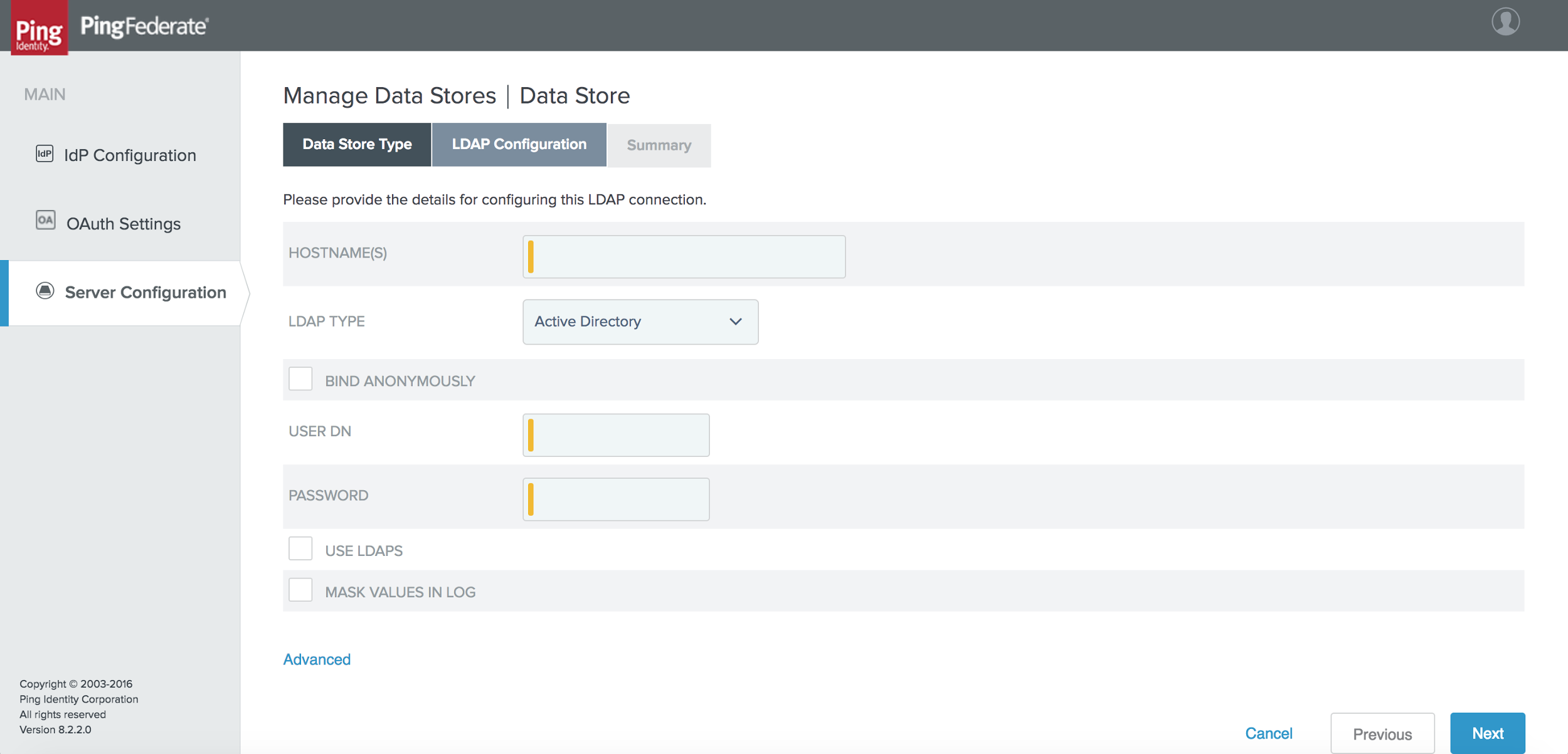
4.2 How to Install and Configure the SAML Identity Provider
On the Server Configuration screen, click Server Settings.
On the Roles & Protocols tab, enable roles and protocols to configure the server as a SAML IdP (Figure 4‑5).
Figure 4‑5 Server Roles for SAML IdP
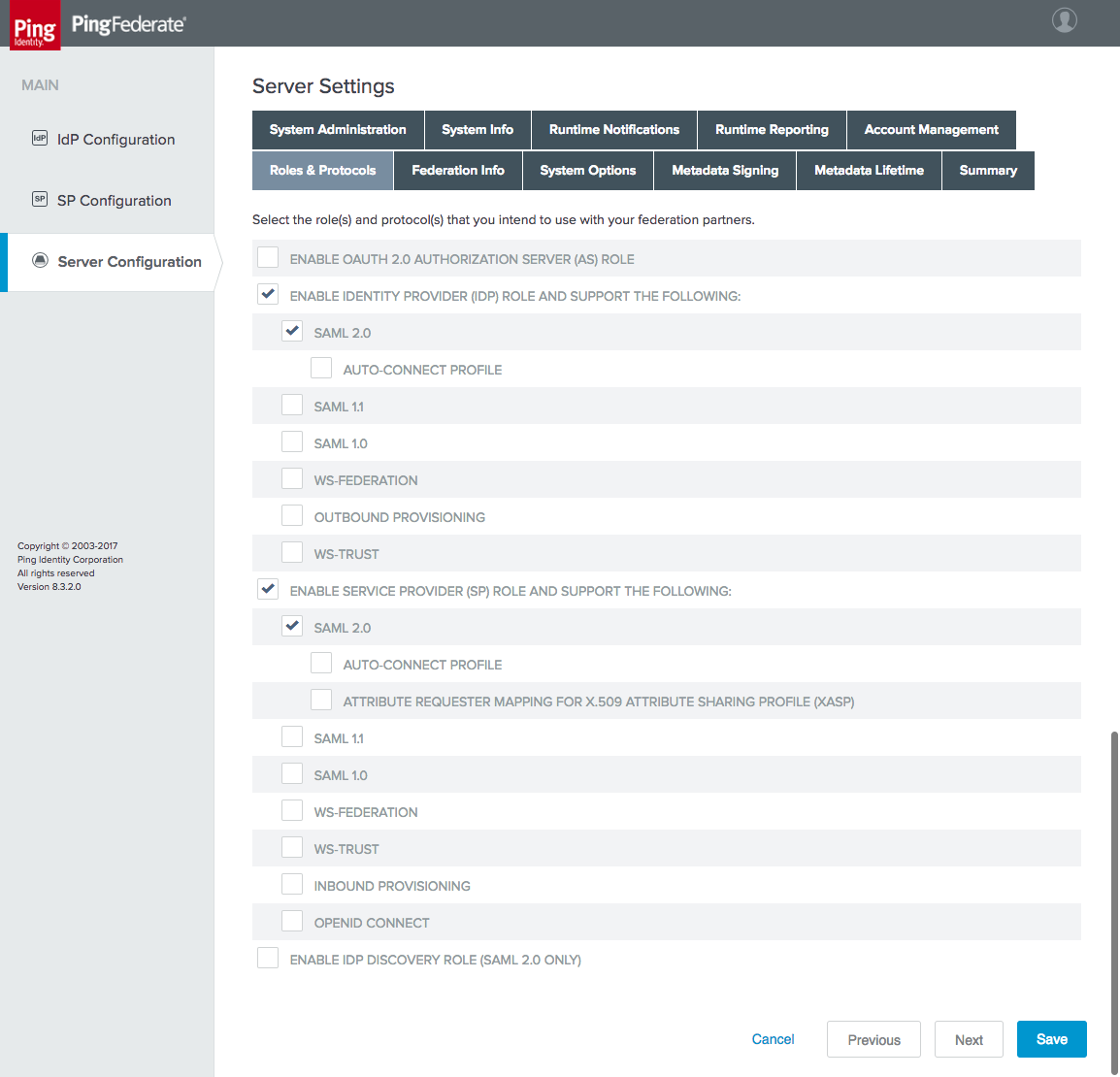
On the Federation Info tab, specify the BASE URL and SAML 2.0 ENTITY ID of the IdP (Figure 4-6). The BASE URL should be a URL resolvable by your mobile clients. The ENTITY ID should be a meaningful name that is unique among federation partners; in this case, the FQDN of the server is used.
Figure 4‑6 SAML IdP Federation Info
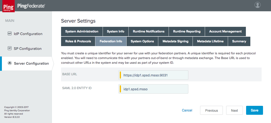
4.2.1 Configuring Authentication to the IdP
This example configures an authentication policy that requires the user to authenticate with username and password and then with a FIDO U2F token.
4.2.1.1 Configure the Password Validator
On the Server Configuration section tab, click Password Credential Validators under Authentication.
Click Create New Instance.
On the Type tab, for the TYPE, choose LDAP Username Password Credential Validator (Figure 4‑7). This example will authenticate AD usernames and passwords by using the AD data store defined in Section 4.1.
Figure 4‑7 Create Password Credential Validator
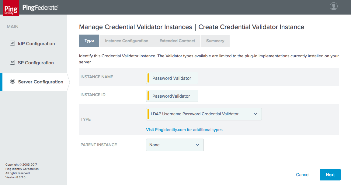
On the Instance Configuration tab, specify the parameters for searching the LDAP directory for user accounts (Figure 4‑8). Select the data store created in Section 4.1, and enter the appropriate search base and filter. This example will search for a sAMAccountName matching the username entered on the login form.
Figure 4‑8 Credential Validator Configuration
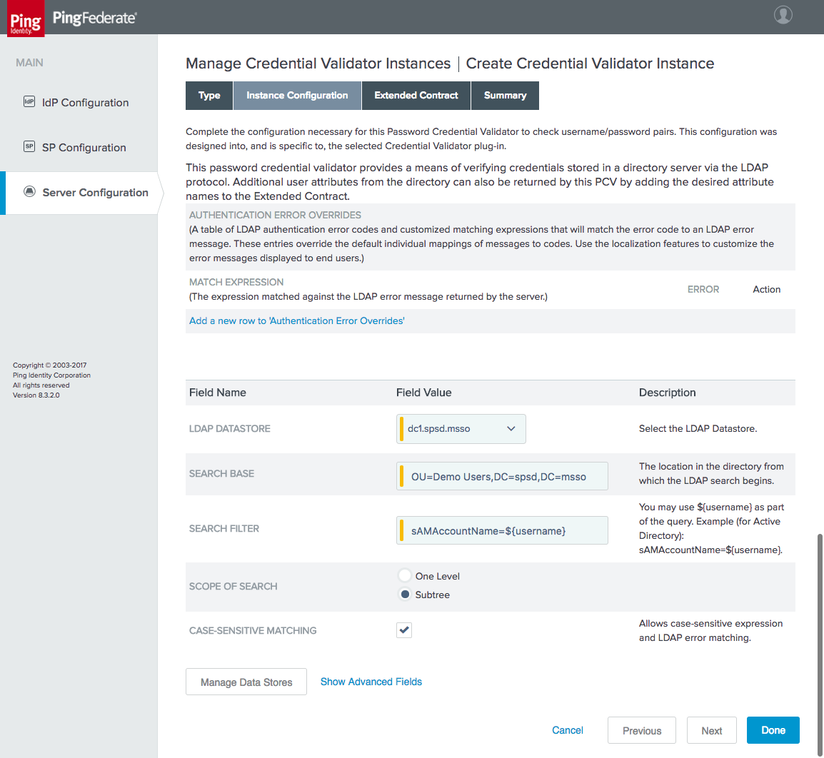
The Extended Contract tab enables the retrieval of additional attributes from the LDAP server, which can be used in assertions to RPs (Figure 4‑9). The example shown in Figure 4‑9 adds several AD attributes to the contract.
Figure 4‑9 Password Credential Validator Extended Contract
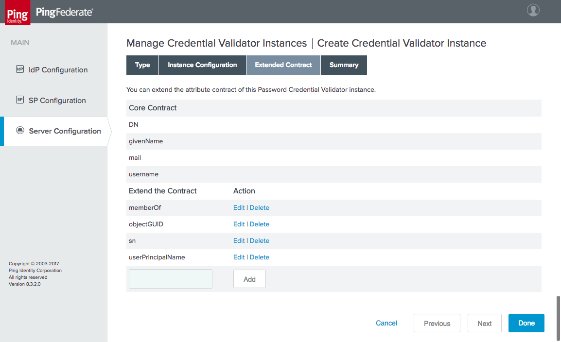
Finally, the Summary tab shows all of the values for the configured validator (Figure 4‑10).
Figure 4‑10 Password Validator Summary

Click Done, and then click Save to complete the setup of the password validator.
4.2.1.2 Configure the HTML Form Adapter
On the IdP Configuration section tab, click Adapters.
Click Create New Instance.
On the Type tab, create the name and ID of the adapter, and select the HTML Form IdP Adapter for the TYPE (Figure 4‑11).
Figure 4‑11 HTML Form Adapter Instance
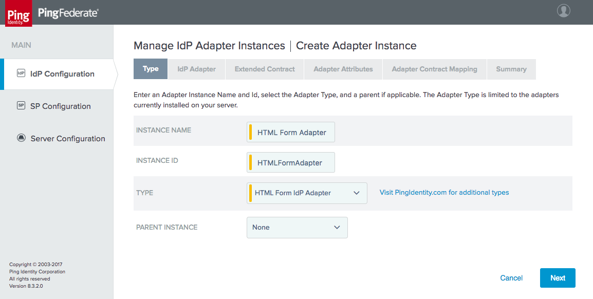
On the IdP Adapter tab, add the Password Validator instance created in the previous section (Figure 4‑12). This tab provides several options for customizing the login page and supporting password resets and password recovery that would be relevant to a Production deployment. In the lab, password resets were not supported, and these fields stayed at their default values.
Figure 4‑12 Form Adapter Settings
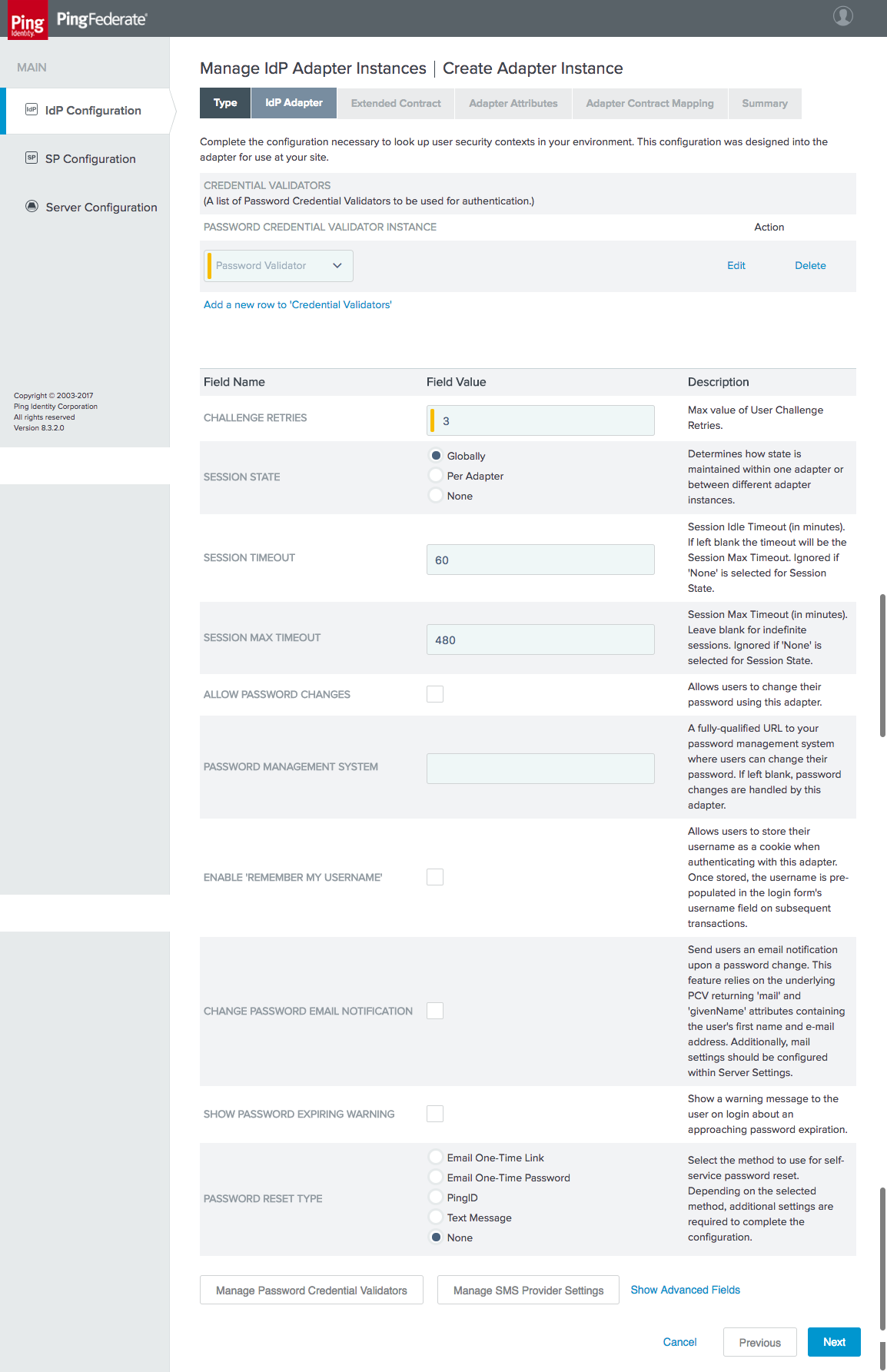
On the Extended Contract tab, the same attributes returned from AD by the Password Validator are added to the adapter contract to make them available for further use by the IdP (Figure 4‑13).
Figure 4‑13 Form Adapter Extended Contract
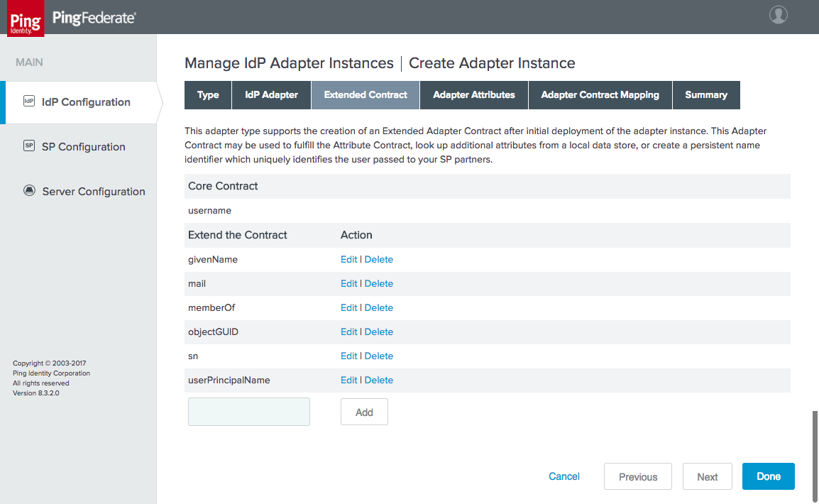
On the Adapter Attributes tab, select the Pseudonym checkbox for the username attribute.
There is no need to configure anything on the Adapter Contract Mapping tab, as all attributes are provided by the adapter. Click Done, and then click Save to complete the Form Adapter configuration.
4.2.1.3 Configure the FIDO U2F Adapter
Before this step can be completed, the FIDO U2F server, StrongKey CryptoEngine (SKCE), must be installed and configured, and the StrongKey U2F adapter for PingFederate must be installed on the IdP. See Section 6 for details on completing these tasks.
On the IdP Configuration section tab, click Adapters.
Click Create New Instance.
Enter meaningful values for INSTANCE NAME and INSTANCE ID. For the TYPE, select “StrongAuth FIDO Adapter.” Click Next.
Figure 4‑14 Create U2F Adapter Instance
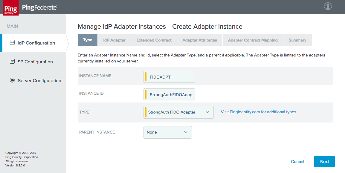
On the IdP Adapter tab, keep the default value of the HTML FORM TEMPLATE NAME to use the template that is provided with the StrongKey U2F plugin, or specify a custom template if desired to change the design of the user interface (Figure 4‑15). The FIDO SERVER URL, DOMAIN ID, SKCE SERVICE USER, and SKCE SERVICE USER PASSWORD are determined in the setup of the SKCE; refer to Section 6 for details.
Figure 4‑15 U2F Adapter Settings
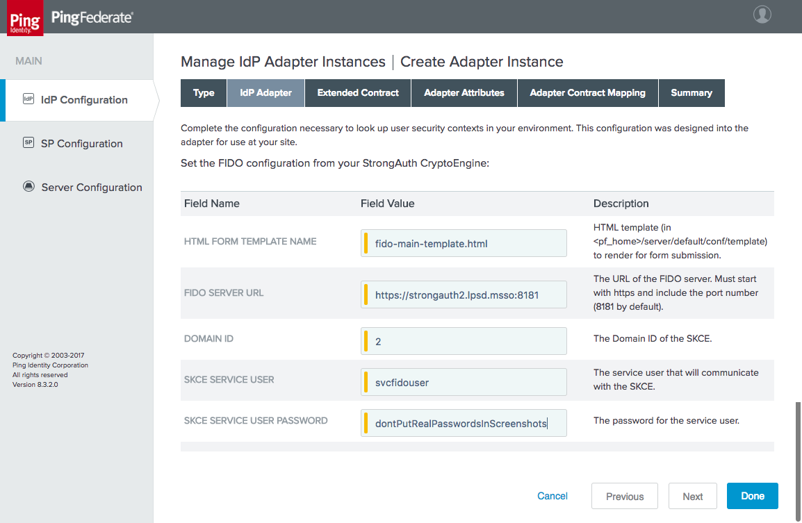
There is no need to extend the contract for the U2F adapter; therefore, skip the Extended Contract tab.
On the Adapter Attributes tab, select the Pseudonym checkbox for the username attribute.
There is also no need for an Adapter Contract Mapping; therefore, skip the Adapter Contract Mapping tab.
Click Done, and then click Save.
4.2.1.4 Configure the Authentication Policies
On the IdP Configuration page, click Policies.
Under Manage Authentication Policies, click the ENABLE IDP AUTHENTICATION POLICIES checkbox, and create a policy that starts with the HTML Form Adapter action (Figure 4‑16).
On the Success branch, add the FIDO U2F adapter (FIDOADPT) for the Action.
Click Save.
Figure 4‑16 IdP Authentication Policy
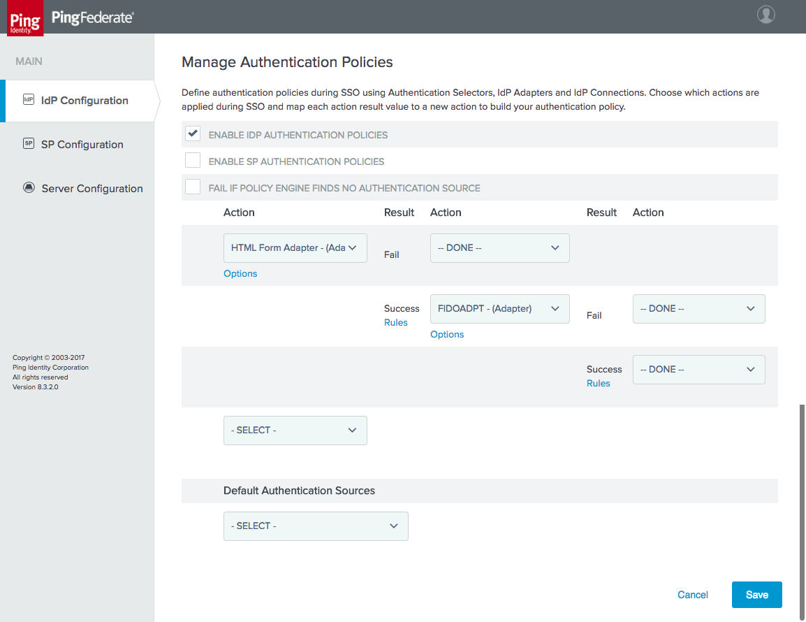
4.2.2 Configure the SP Connection
Each RP that will receive authentication assertions from the IdP must be configured as an SP connection. As explained in Section 3.4.2.1, this activity requires coordination between the administrators of the IdP and the RP to provide the necessary details to configure the connection. Exchanging metadata files can help automate some of the configuration process.
This section documents the configuration for the SP connection between the SAML IdP in the NCCoE lab and the OAuth AS in the Motorola Solutions cloud instance.
To create a new SP connection, click the IdP Configuration section tab, and then click Create New under SP Connections.
On the Connection Type tab, select BROWSER SSO PROFILES, and select the SAML 2.0 protocol (Figure 4‑17). In this case, SAML 2.0 is pre-selected because no other protocols are enabled on this IdP.
Figure 4‑17 SP Connection Type
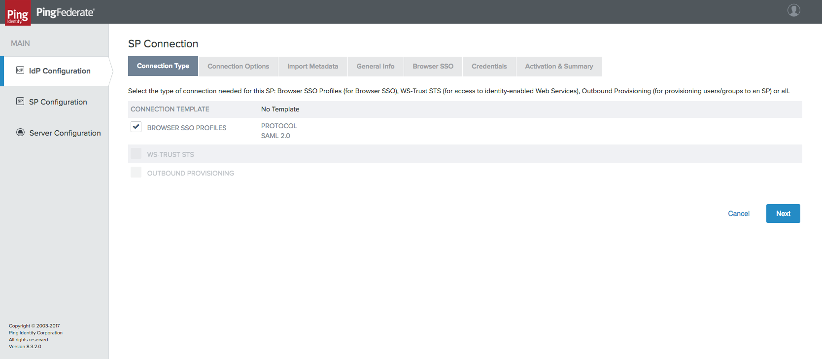
On the Connection Options tab, only BROWSER SSO needs to be selected.
If metadata for the SP is available, it can be imported on the Import Metadata tab. This metadata can be specified in the form of a file upload or URL.
On the General Info tab, enter the PARTNER’S ENTITY ID (CONNECTION ID) (Figure 4‑18); this must match the ENTITY ID configured on the Federation Info tab in the Server Configuration of the SP. The SP’s BASE URL should also be added on this General Info tab.
Figure 4‑18 SP Connection General Info
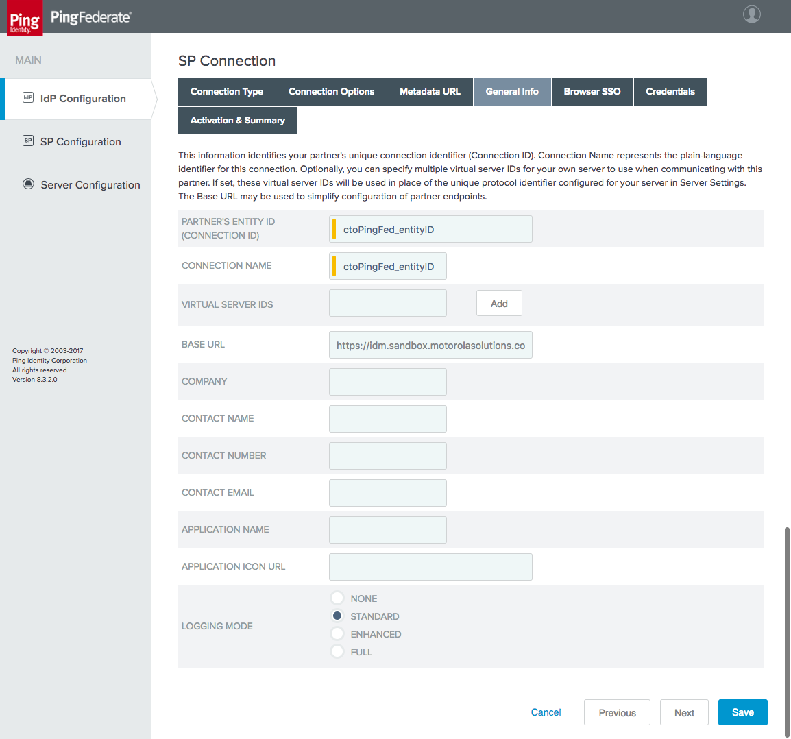
On the Browser SSO tab, click Configure Browser SSO. This opens another multi-tabbed configuration screen.
On the SAML Profiles tab, different SSO and Single Log-Out (SLO) profiles can be enabled (Figure 4‑19). Only SP-INITIATED SSO is demonstrated in this lab build.
Figure 4‑19 SP Browser SSO Profiles
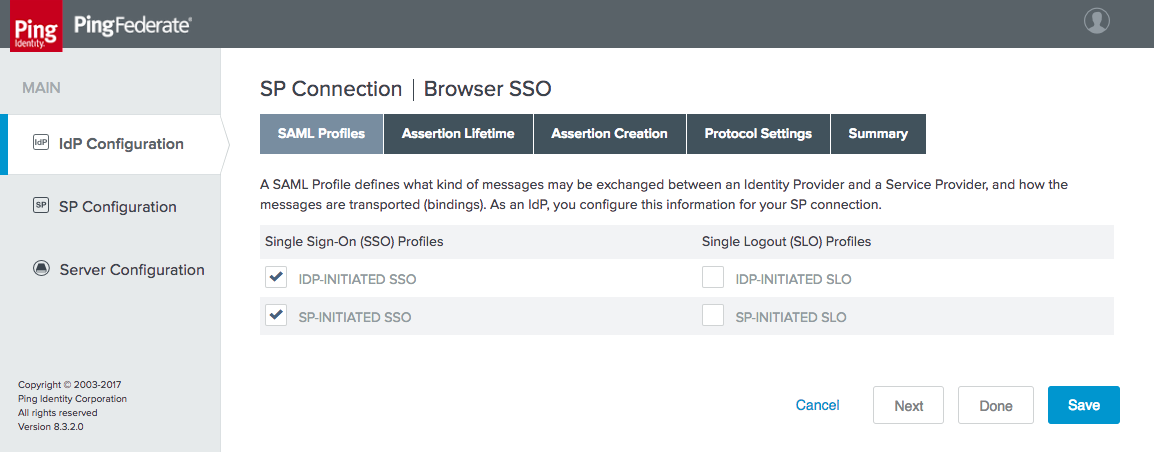
On the Assertion Lifetime tab, time intervals during which SPs should consider assertions valid can be configured in minutes before and after assertion creation. In the lab, these were both set to the default of five minutes.
On the Assertion Creation tab, click Configure Assertion Creation. This opens a new multi-tabbed configuration screen.
On the Identity Mapping tab, select the STANDARD mapping (Figure 4‑20). The other options are more suitable for situations where identifiers are sensitive or where there are privacy concerns over the tracking of users.
Figure 4‑20 Assertion Identity Mapping
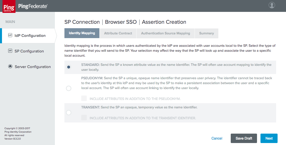
On the Attribute Contract tab, extend the contract to include the mail and uid attributes with the basic name format (Figure 4‑21). Other attributes can be added here as needed.
Figure 4‑21 Assertion Attribute Contract
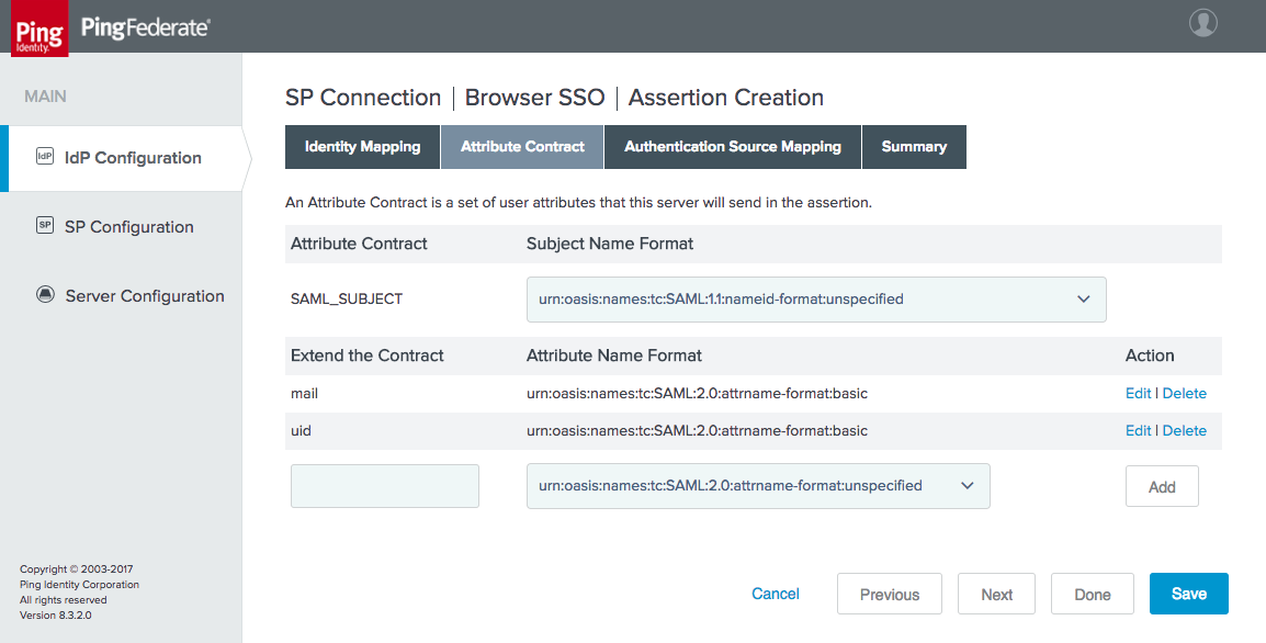
On the Authentication Source Mapping tab, attributes provided by authentication adapters and policy contracts can be mapped to the assertion attribute contract, identifying which data will be used to populate the assertions. The FIDO U2F adapter and the HTML Form Adapter should appear under Adapter Instance Name. Select the HTML Form Adapter, as it can provide the needed attributes from LDAP via the Password Validator and the AD data store connection. This brings up another multi-tabbed configuration screen.
The Adapter Instance tab shows the attributes that are returned by the selected adapter. Click Next.
The Mapping Method tab provides options to query additional data stores to build the assertions, but in this case, all of the required attributes are provided by the HTML Form Adapter. Select USE ONLY THE ADAPTER CONTRACT VALUES IN THE SAML ASSERTION.
On the Attribute Contract Fulfillment tab, map the SAML_SUBJECT, mail, and uid attributes to the username, mail, and userPrincipalName adapter values (Figure 4‑22).
Figure 4‑22 Assertion Attribute Contract Fulfillment
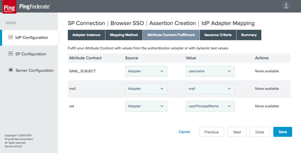
No Issuance Criteria are required; therefore, skip the Issuance Criteria tab.
Click Done to exit the IdP Adapter Mapping.
Click Done to exit the Assertion Creation.
On the Protocol Settings tab, options such as additional SAML bindings, signature policy details, and assertion encryption policies can be specified (Figure 4‑23). For the lab build, these values stayed at their default settings.
Figure 4‑23 Browser SSO Protocol Settings
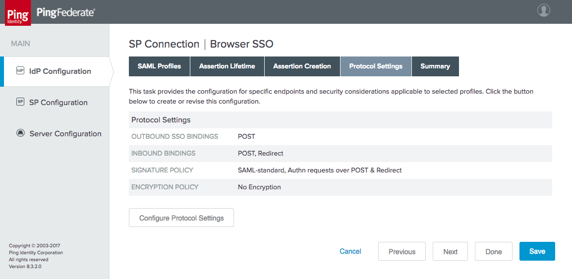
Click Done to exit Browser SSO.
On the Credentials tab, the certificate to use for signing assertions can be specified. A self-signed certificate can be generated by PingFederate, or a trusted certificate can be obtained and uploaded. Click Configure Credentials to create or manage signing credentials.
On the Activation & Summary tab, the connection status can be set to ACTIVE. All configured settings for the SP connection are also displayed for verification.
Click Save to complete the SP connection configuration.
This completes the configuration of the SAML IdP.
4.3 How to Install and Configure the OIDC Identity Provider
On the Server Configuration section tab, click Server Settings.
On the Roles & Protocols tab, enable the roles and protocols as shown in Figure 4‑24. Although the OIDC IdP does not actually use the SAML protocol, some required configuration settings are unavailable if the IdP role is not enabled.
Figure 4‑24 OIDC IdP Roles
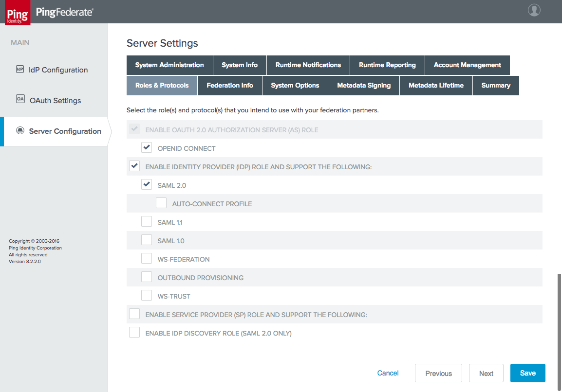
On the Federation Info tab, specify the BASE URL and SAML 2.0 ENTITY ID. The BASE URL must be a URL that is exposed to clients.
On the OAuth Settings section tab, click Authorization Server Settings to configure general OAuth and OIDC parameters. The OIDC IdP’s settings on this page are identical to those for the OAuth AS; refer to Section 3.3 for notes on these settings.
On the OAuth Settings section tab, click Scope Management. Add the scopes defined in the OpenID Connect Core specification [C25]:
openid
profile
address
phone
4.3.1 Configuring Authentication to the OIDC IdP
In the lab architecture, the OIDC IdP supports FIDO UAF authentication through integration with the NNAS and the Nok Nok Labs Gateway, using the Nok Nok FIDO UAF adapter for PingFederate. Configuring UAF authentication to the OIDC IdP cannot be completed until the Nok Nok Labs servers are available and the UAF plugin has been installed on the IdP server as specified in Section 5.
4.3.1.1 Configure the FIDO UAF Plugin
The steps to configure the FIDO UAF plugin for the OIDC IdP are identical to those documented in Section 3.4.1.1 for direct authentication using UAF at the AS. The only difference in the lab build was the URLs for the NNAS and the Nok Nok Labs Gateway, as the AS and the OIDC IdP used two different instances of the Nok Nok Labs server.
4.3.1.2 Configure an Access Token Management Instance
On the OAuth Settings section tab, click Access Token Management.
Click Create New Instance.
On the Type tab, provide an INSTANCE NAME and INSTANCE ID (Figure 4‑25).
Select Internally Managed Reference Tokens for the TYPE.
Figure 4‑25 Create Access Token Manager
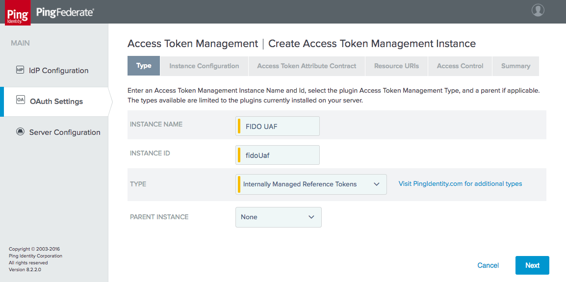
Although we have selected reference tokens, the ID Token is always issued in the form of a JWT. The token that is being configured here is not the ID Token, but rather the access token that will be issued to authorize the RP to call the userinfo endpoint at the IdP to request additional claims about the user. Because this access token only needs to be validated by the OIDC IdP itself, reference tokens are sufficient. In the Authorization Code flow, the RP obtains both the ID Token and the access token in exchange for the authorization code at the IdP’s token endpoint.
Click the Instance Configuration tab to configure some security properties of the access token, such as its length and lifetime (Figure 4‑26). For the lab build, the default values were accepted.
Figure 4‑26 Access Token Manager Configuration
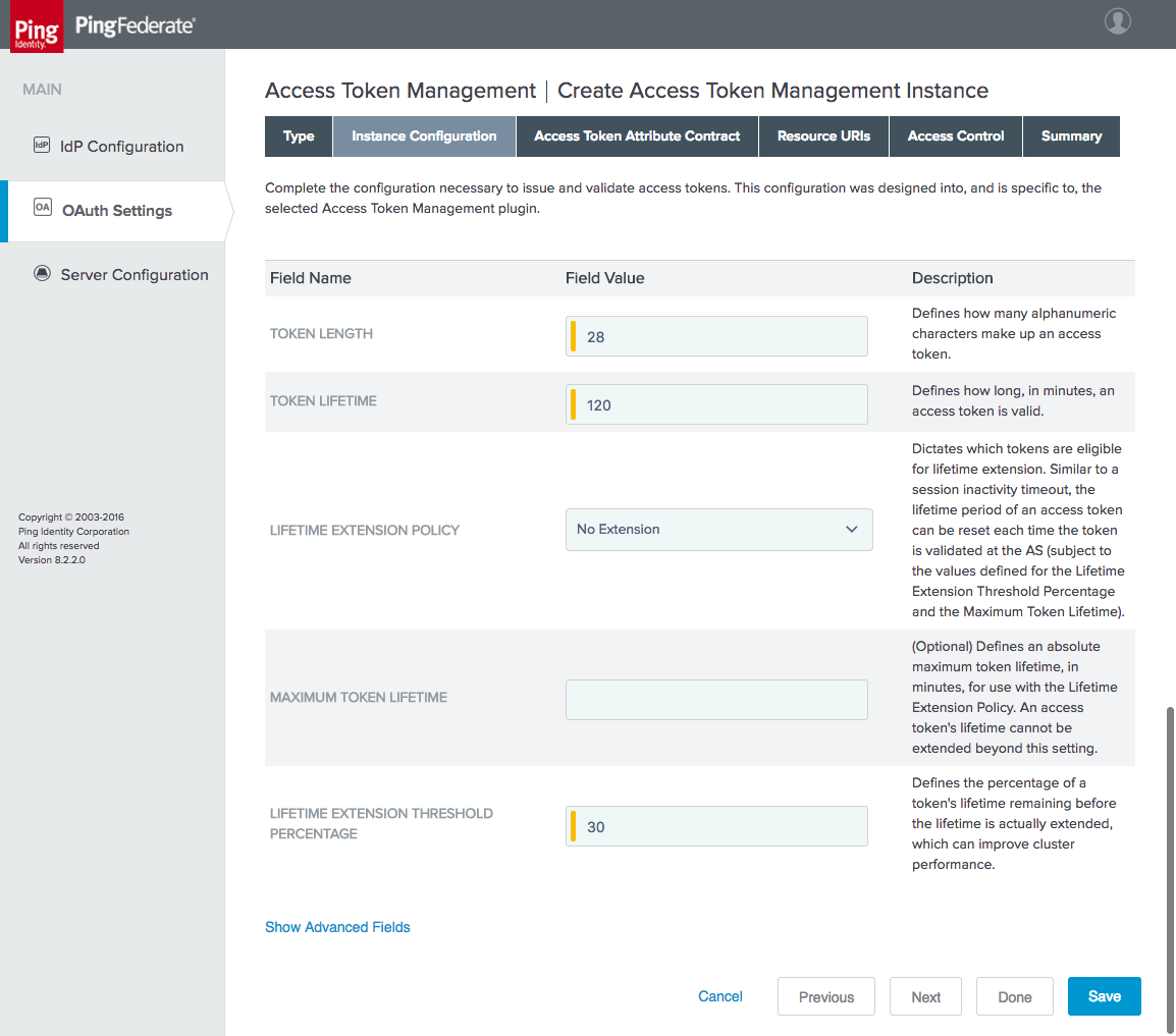
On the Access Token Attribute Contract tab, extend the contract with any attributes that will be included in the ID Token (Figure 4‑27). In the example shown in Figure 4‑27, several attributes that will be queried from AD have been added.
Figure 4‑27 Access Token Attribute Contract
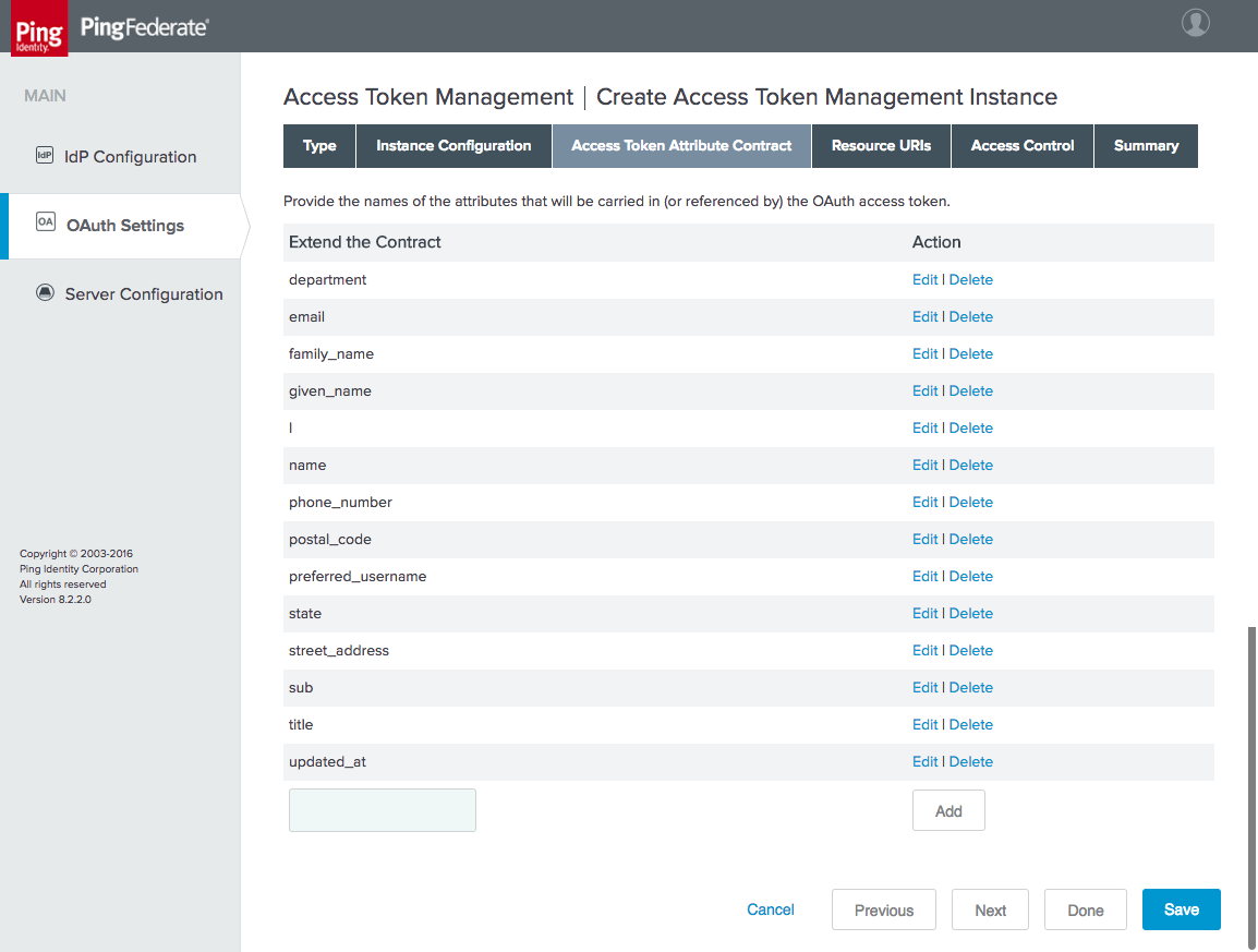
There is no need to configure the Resource URIs or Access Control tabs; these tabs can be skipped.
Click Done, and then click Save.
4.3.1.3 Configure an IdP Adapter Mapping
The IdP Adapter Mapping determines how the persistent grant attributes are populated using information from authentication adapters.
Click the OAuth Settings section tab, and then click IdP Adapter Mapping.
Select the UAF adapter instance created in Section 4.3.1.1, and then click Add Mapping.
On the Contract Fulfillment tab, map both USER_KEY and USER_NAME to the username value returned from the adapter (Figure 4‑28).
Figure 4‑28 Access Token Contract Fulfillment
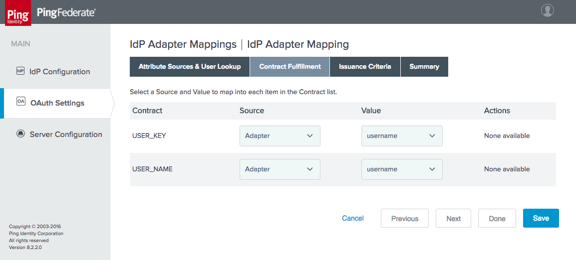
4.3.1.4 Configure an Access Token Mapping
The Access Token Mapping determines how the access token attribute contract is populated. In this example, the values returned from the adapter are supplemented with attributes retrieved from AD, and issuance criteria are used to require the user to be actually found in AD for a token to be issued. Depending on the credential and access life-cycle processes used in a given organization, there may be a lag in deactivating the authenticator or the AD account when a user’s access is terminated. Organizations’ authentication policies should account for these conditions and should allow or deny access appropriately.
On the OAuth Settings section tab, click Access Token Mapping.
Under CONTEXT and ACCESS TOKEN MANAGER, select the IdP Adapter and Access Token Manager created in the preceding steps, and click Add Mapping.
On the Attribute Sources & User Lookup tab, click Add Attribute Source. This brings up another multi-tabbed configuration.
On the Data Store tab, give the attribute source an ID and description (Figure 4‑29). For ACTIVE DATA STORE, select the user store created in Section 4.1.
Figure 4‑29 Data Store for User Lookup
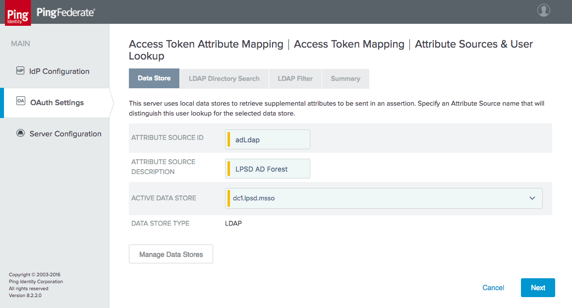
On the LDAP Directory Search tab, specify the BASE DN and SEARCH SCOPE, and add the AD attributes to be retrieved (Figure 4‑30). When specifying attributes, it is necessary to first select the root object class that contains the attribute. Common attributes associated with user accounts may be derived from the User or OrganizationalPerson class, for example. Refer to Microsoft’s AD Schema documentation [C26] to identify the class from which a given attribute is derived.
Figure 4‑30 Attribute Directory Search
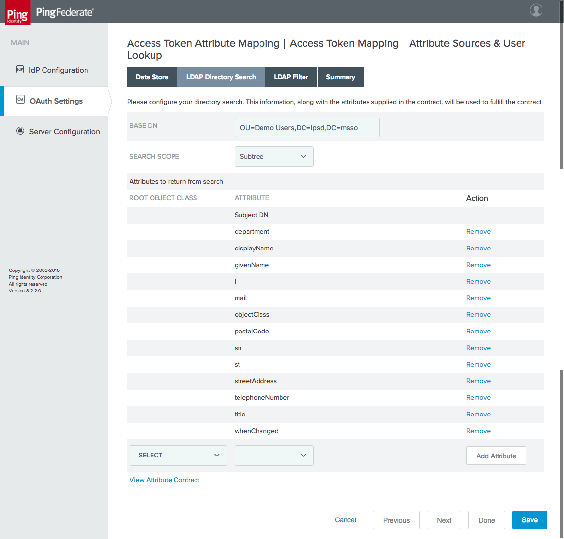
On the LDAP Filter tab, create the filter to select the relevant user account. In this example, the username from the adapter is matched against the AD SAM account name:
sAMAccountName=${adapter.username}Click Done to exit the attribute source configuration.
On the Contract Fulfillment tab, specify the source and value to use for each attribute in the access token attribute contract (Figure 4‑31).
Figure 4‑31 Access Token Contract Fulfillment
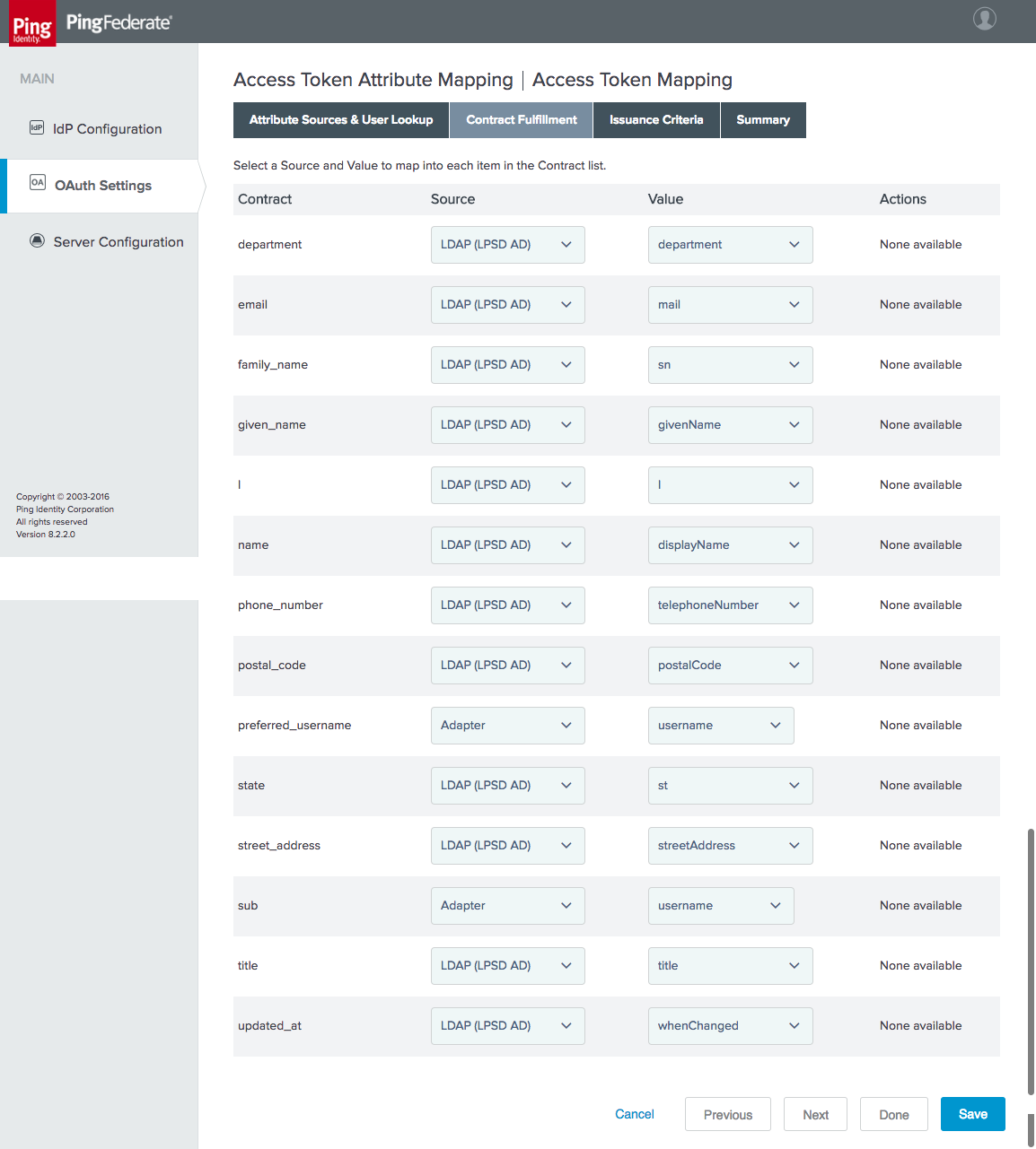
On the Issuance Criteria tab, define a rule that will prevent token issuance if the user account doesn’t exist in AD (Figure 4‑32). In this case, the objectClass attribute, which all AD objects have, is checked for the Value called user. If no user account is found in AD, this attribute will have no Value, the Condition will be false, and the specified Error Result will appear in the PingFederate server log.
Figure 4‑32 Access Token Issuance Criteria
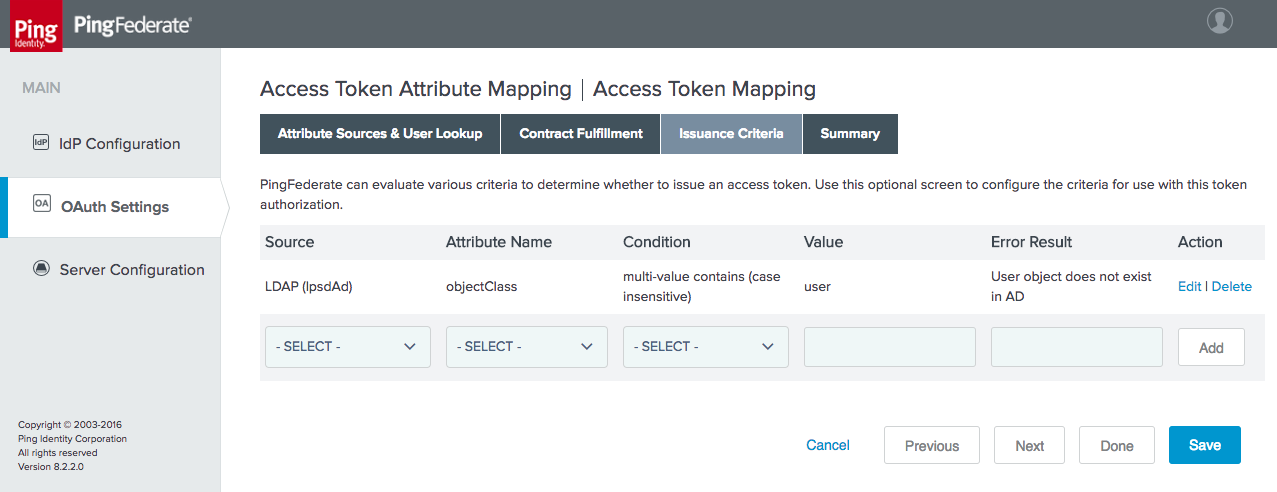
Click Done, and then click Save to finish the Access Token Attribute Mapping configuration.
4.3.1.5 Configure an OIDC Policy
On the OAuth Settings tab, click OpenID Connect Policy Management.
Click Add Policy.
On the Manage Policy tab, create a POLICY ID and NAME, and select the INCLUDE USER INFO IN ID TOKEN checkbox (Figure 4‑33). This selection means that the user’s attributes will be included as claims in the ID Token JWT. The advantage of this approach is that the RP can directly obtain user attributes from the ID Token without making additional requests to the IdP. The alternative is to include only a subject claim in the ID Token, and to have the RP call the IdP’s userinfo endpoint to obtain additional user attributes.
Figure 4‑33 OIDC Policy Creation
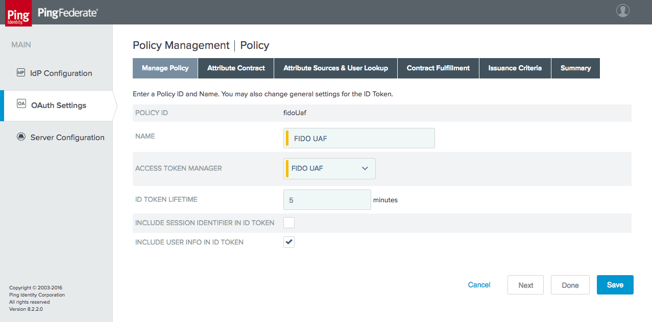
On the Attribute Contract tab, the set of attributes in the contract can be edited (Figure 4‑34). The contract is automatically populated with the standard claims defined in the OIDC Core specification. In the example shown in Figure 4‑34, some claims have been removed and others have been added to accommodate the attribute available from AD.
Figure 4‑34 OIDC Policy Attribute Contract
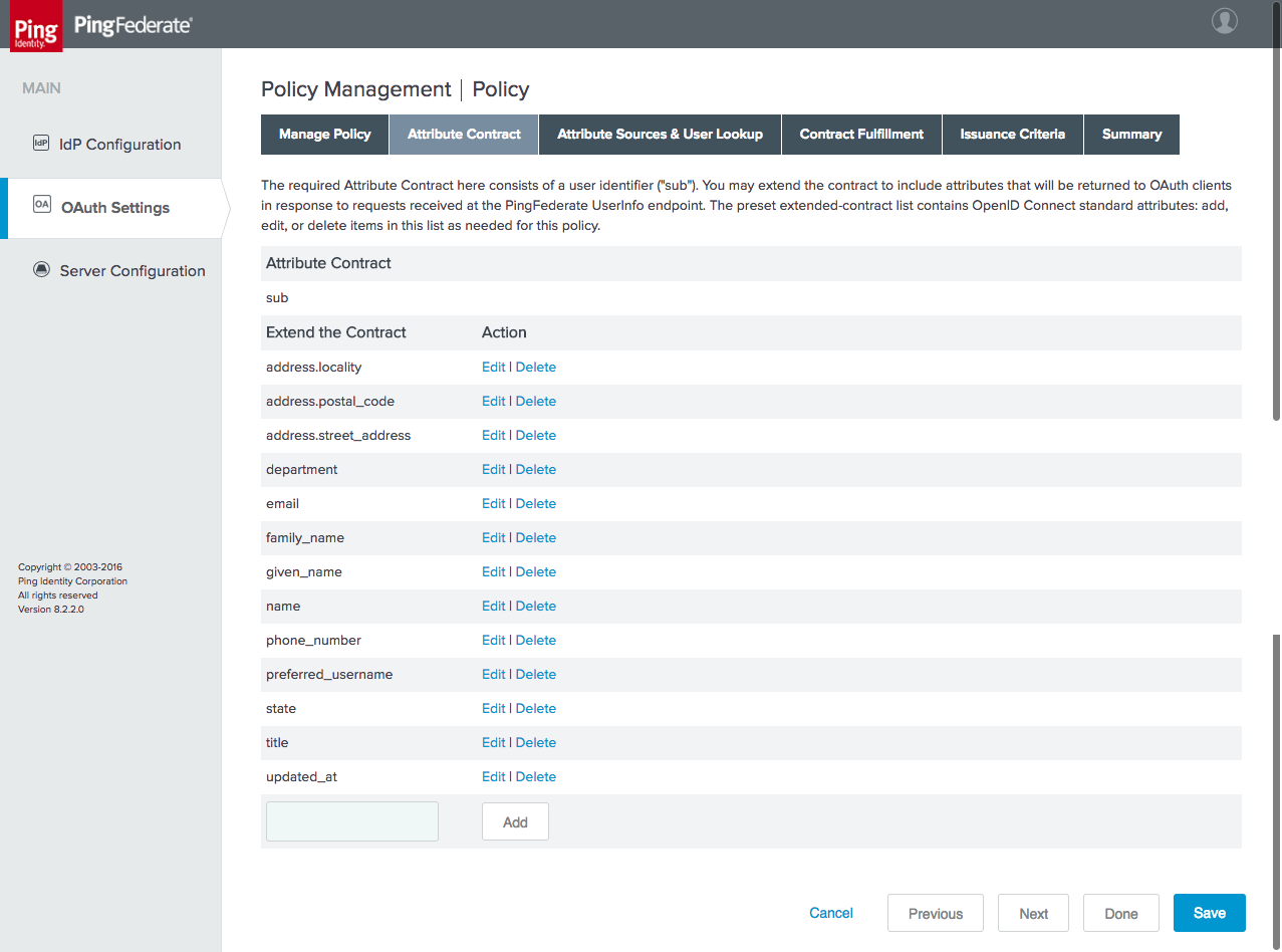
Skip the Attribute Sources & User Lookup tab; there is no need to retrieve additional attributes.
On the Contract Fulfillment tab, populate the OIDC attributes with the corresponding values from the Access Token context (Figure 4‑35).
Figure 4‑35 OIDC Policy Contract Fulfillment
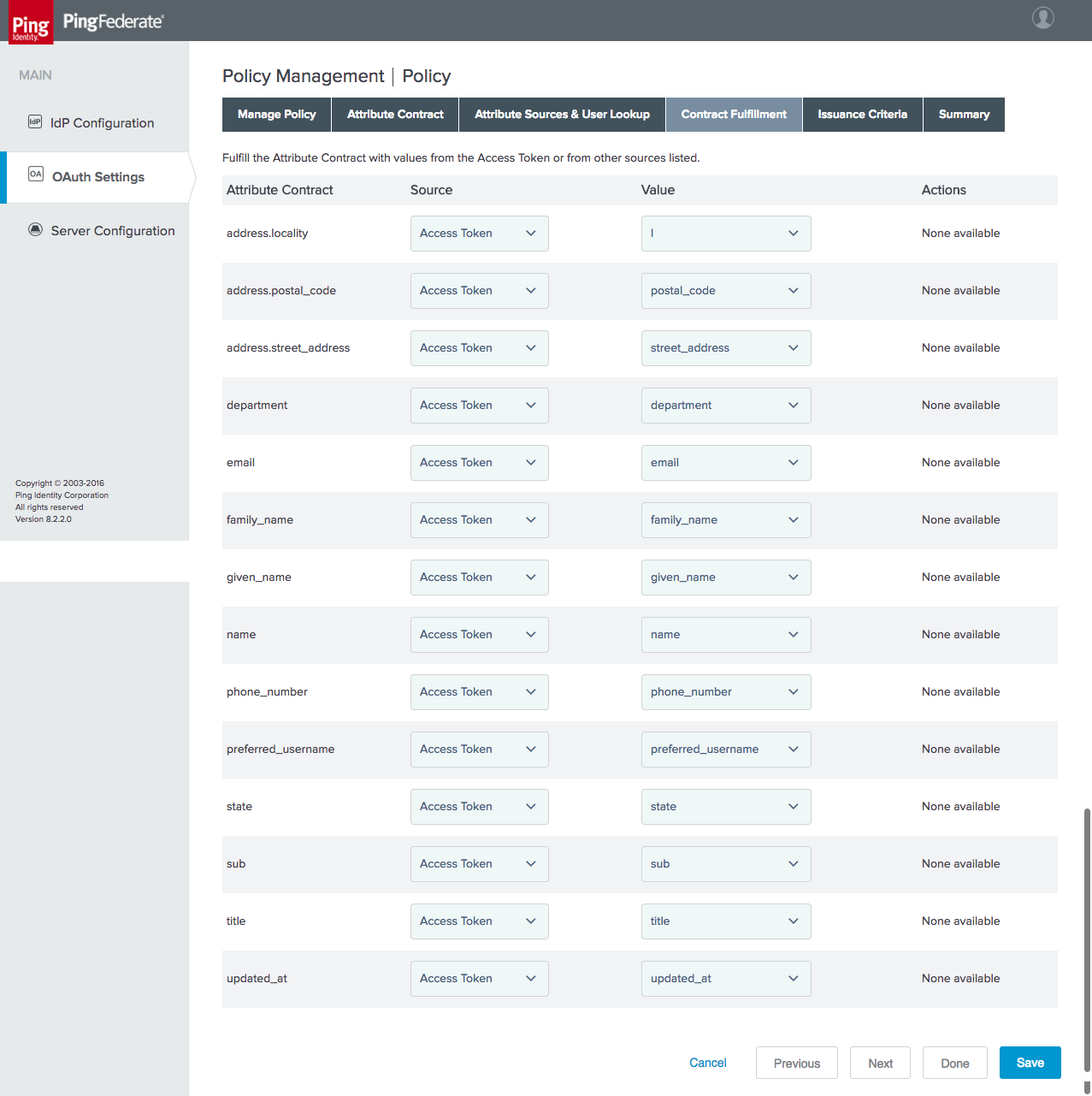
There is no need for additional issuance criteria; therefore, skip the Issuance Criteria tab.
Click Save to complete the OIDC Policy configuration.
4.3.2 Configuring the OIDC Client Connection
Registering a client at an OIDC IdP is analogous to creating an SP connection at a SAML IdP. Some coordination is required between the administrators of the two systems. The client ID and client secret must be provided to the RP, and the RP must provide the redirect URI to the IdP.
To add a client, click the OAuth Settings section tab, and then click Create New under Clients.
- Create a CLIENT ID and CLIENT SECRET (Figure 4‑36). If mutual TLS authentication is being used instead, the RP must provide its certificate, which can be uploaded to the client creation page. Only the Authorization Code grant type is needed for this integration. In the example shown in Figure 4‑36, user prompts to authorize the sharing of the user’s attributes with the RP have been disabled in favor of streamlining access to applications.
Figure 4‑36 OIDC Client Configuration
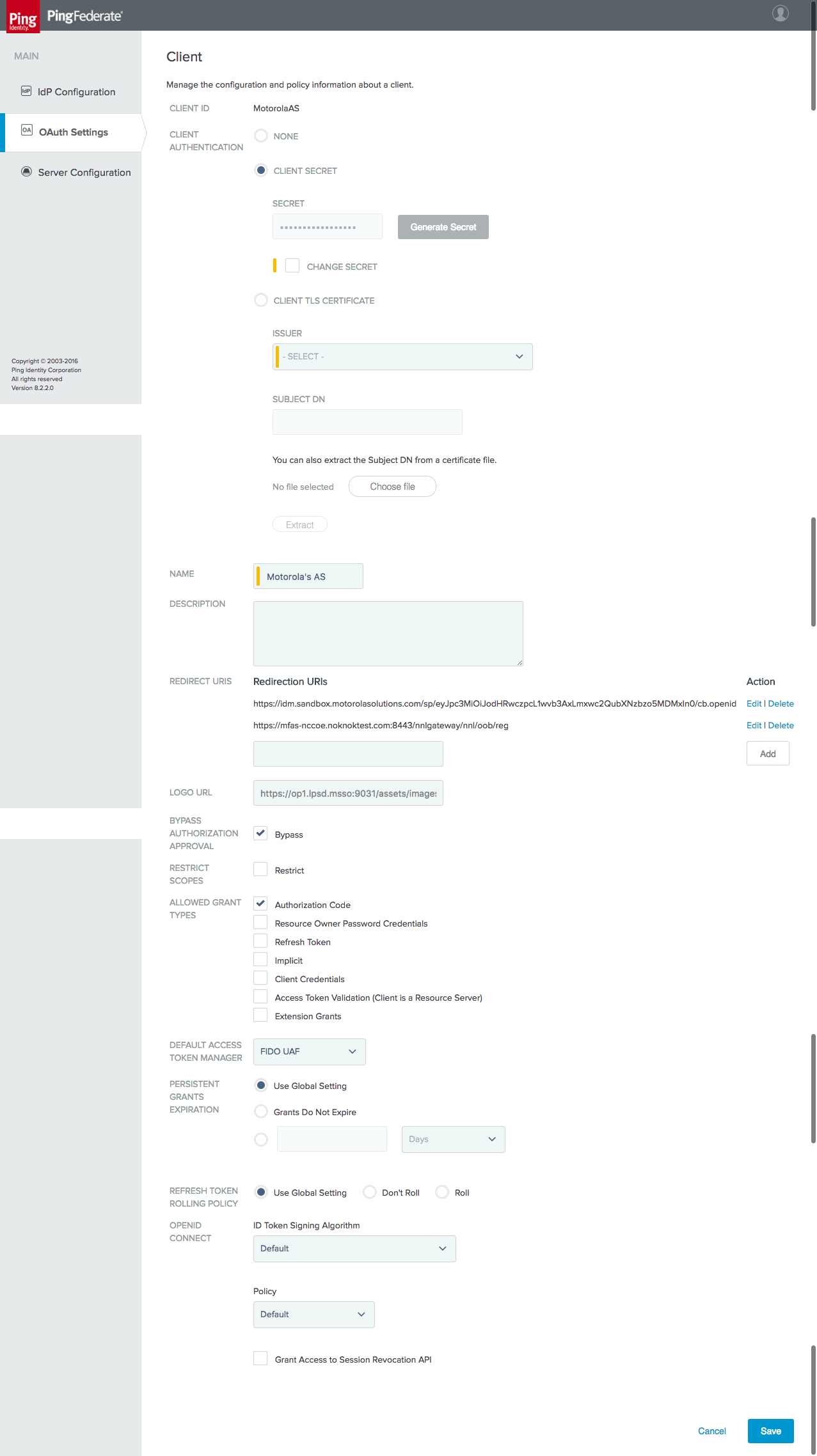
This completes configuration of the OIDC IdP.
5 How to Install and Configure the FIDO UAF Authentication Server
For the lab build environment, the Nok Nok Labs S3 Authentication Suite provides FIDO UAF integration. The S3 Authentication Suite can support a variety of different deployments and architectures, as described in the Solution Guide [C27]. This section briefly describes the overall deployment architecture used for this build.
The Nok Nok Labs SDKs can be directly integrated into mobile applications, providing UAF client functionality directly within the application. This deployment would be more suitable to use cases that do not involve federation, where the requirement is to authenticate users directly at the application back end. Nok Nok Labs also provides “Out-of-Band” (OOB) integration. OOB can support workflows where a mobile device is used for true OOB authentication of logins or transactions initiated on another device, such as a laptop or workstation. OOB also can be used for authentication flows in a mobile web browser, including OAuth authorization flows or IdP authentication, as implemented in this build by using the AppAuth pattern.
When OOB is used in a cross-device scenario, the user must first register the mobile device by scanning a QR code displayed in the browser. Subsequent authentication requests can be sent by push notification to the registered device. When the OOB flow is initiated in a mobile browser, however, the authentication request can be sent directly to the application running the Nok Nok Labs SDK by using mobile platform technologies to open links directly in mobile applications (App Links for Android, or Universal Links for iOS). The FIDO client that processes the OOB authentication request can be either a custom application incorporating the Nok Nok Labs SDK, or the Nok Nok Labs Passport application, which provides a ready-made implementation.
The components of the Nok Nok Labs deployment for this build architecture are as follows:
Nok Nok Labs Passport—provides UAF client functionality as well as Authenticator-Specific Modules (ASMs) and authenticators on the mobile device
Nok Nok Labs PingFederate UAF Adapter—a PingFederate plugin providing integration between a PingFederate AS or IdP and the NNAS, enabling UAF authentication or transaction verification to be integrated into PingFederate authentication policies
NNAS—provides core UAF server functionality, including the generation and verification of challenges, as well as APIs for interactions with UAF clients and the PingFederate Adapter
Nok Nok Labs Gateway—provides a simplified interface to request FIDO operations from the Authentication Server, as well as integration with the existing application session management infrastructure
Nok Nok Labs Gateway Tutorial Application—a demonstration web application implementation that provides simple U2F and UAF authentication and registration workflows
In a typical production implementation, the gateway functions for authenticator management (registration and de-registration) would require strong authentication implemented through the Gateway’s session management integration. Nok Nok Labs’ documentation for the PingFederate plugin provides examples for defining a “reg” OAuth scope to request authenticator registration. An OAuth Scope Authentication Selector could be used in a PingFederate authentication policy to trigger the required strong authentication process.
5.1 Platform and System Requirements
The following subsections list the hardware, software, and network requirements for the various Nok Nok Labs components.
5.1.1 Hardware Requirements
Nok Nok Labs specifies the following minimum hardware requirements for the NNAS and Nok Nok Labs Gateway components. The requirements for acceptable performance will depend on the anticipated user population and server load. See the Enabling Scalability & Availability section of the Solution Guide for architecture guidance on deploying the NNAS in a clustered configuration.
Processor: 1 CPU
Memory: 4 GB RAM
Hard disk drive size: 10 GB
5.1.2 Software Requirements
Complete software requirements for the NNAS are provided in the Nok Nok Labs Authentication Server Administration Guide [C28]. The major requirements are summarized below:
OS: Red Hat Enterprise Linux 7 or CentOS 7
Relational database system: MySQL 5.7.10 or later versions, Oracle Database 12c, or PostgreSQL 9.2 or 9.4
Application server: Apache Tomcat 8.0.x or 8.5.x
Java: Oracle JDK Version 8
Build tool: Apache Ant 1.7 or later versions
For clustered deployments: Redis 2.8 or later versions
Google Cloud Messenger (GCM) or Apple Push Notification System (APNS), if using push messages
The Nok Nok Labs PingFederate Adapter is compatible with PingFederate 8.1.3 or later versions.
The Nok Nok Labs Gateway is also deployed in Tomcat.
5.2 How to Install and Configure the FIDO UAF Authentication Server
The installation process for the Authentication Server is documented in the Administration Guide. A high-level summary is provided below, with notes relevant to the lab build:
Install the OS and dependent software, including Java and Tomcat. The database can be installed on the same host as Tomcat, or remotely. Provision a TLS certificate for the server and configure Tomcat to use TLS.
The configuration for push notifications to support OOB authentication is not required for this build; push notifications would be used when the mobile device is used to authenticate logins or transactions initiated on a separate device.
Follow the instructions to generate an encryption key and encrypt database credentials in the installation script. Encrypting the push notification credentials is not required, unless that functionality will be used.
For this lab build, the standalone installation was used. The standalone option uses the PostgreSQL database on the same host as the Authentication Server and also installs the Tutorial application.
After running the installation script, delete the encryption key (
NNL_ENCRYPTION_KEY_BASE64) from nnl-install-conf.sh.For this lab build, the default policies and authenticators were used. In a production deployment, policies could be defined to control the authenticator types that could be registered and used to authenticate.
Provisioning a Facet ID is not necessary for the OOB integration with Nok Nok Labs Passport, as used in the lab. If the Nok Nok Labs SDK were integrated with a custom mobile application, then the Facet ID would need to be configured, and the facets.uaf file would need to be published at a URL where it is accessible to clients.
Application link/universal link integration (optional)—In the lab, the default setting using an application link under https://app.noknok.com was used. This is acceptable for testing, but in a production deployment, an application link pointing to the IdP’s actual domain name would typically be used. It should be noted that the FQDN for the application link must be different from the authentication endpoint (i.e., the IdP’s URL) at least by sub-domain.
Configure tenant-specific and global parameters. For the lab build, a single tenant was used. Many parameters can stay at the default settings. Some notes on specific parameters are provided below:
uaf.application.id—This should be a URL that is accessible to clients. In a production deployment, the AS may not be accessible, so this may need to be hosted on a different server.uaf.facet.id—There is no need to modify the Facet ID setting to enable the use of the Passport application for OOB authentication; however, if other custom applications were directly integrating the Nok Nok Labs SDK, they would need to be added here.
For a production deployment, client certificate authentication to the Authentication Server should be enabled. This is done by configuring the Tomcat HTTP connector to require client certificates. This requires provisioning a client certificate for the gateway (and any other servers that need to call the Nok Nok Labs APIs). See the notes in Section 5.3 of the Administration Guide about configuring the Gateway to use client certificate authentication. A general reference on configuring TLS in Tomcat 8 can be found at https://tomcat.apache.org/tomcat-8.0-doc/ssl-howto.html.
5.3 How to Install and Configure the FIDO UAF Gateway Server
The Nok Nok Labs Gateway application is delivered as a Web Archive (WAR) file that can be deployed to a Tomcat server. For the lab build, it was deployed on the same server as the NNAS.
Configure the required settings in the nnlgateway.properties file, including the settings listed below:
mfas_location—NNAS URLserver.auth.enabled—should be set to true; also requires configuring the trust-store settingsclient.auth.enabled—see notes in Section 5.2 above; should be enabled for strong client authentication in production deployments; also requires configuring the keystore settings
In addition, the Gateway Tutorial application was installed by deploying the gwtutorial.war file and configuring the required URLs in gwtutorial.properties.
5.4 How to Install and Configure the FIDO UAF Adapter for the OAuth 2 AS
Nok Nok Labs provided a tar file containing a set of software tools for integration and testing with PingFederate. Version 5.1.0.501 of the Ping Integration library was used for the lab build. The installation process is summarized below; refer to the Nok Nok PingFederate Adapter Integration Guide [C29] for full details:
Extract the adapter folder from the nnl-ping-integration-5.1.0.501.tar file onto the PingFederate server where the adapter will be installed.
Stop PingFederate if it is running, and run the installation script. The path to the PingFederate installation is passed as an argument; run the script by using an account with write access to the PingFederate installation:
$ ./adapter-deploy.sh /usr/share/pingfederate-8.2.2/pingfederateConfigure the adapter.properties file (located in the PingFederate directory under server/default/conf) as required for the server and client TLS authentication settings specified earlier in the Authentication Server configuration. If push notifications are enabled, configure the relevant settings.
The Configure Session Manager and Deploy Nok Nok Gateway OOB sections of the Integration Guide provide settings to use PingFederate to protect the Registration endpoint on the Nok Nok Labs Gateway. This could be used in conjunction with the custom “reg” scope and a PingFederate authentication policy to require strong authentication prior to UAF authenticator registration. This configuration was not tested in the lab.
The Configure PingFederate Console section of the Integration Guide walks through the complete configuration of a PingFederate OIDC provider. See Section 4.3 of this guide for the procedure to configure the OpenID Provider.
6 How to Install and Configure the FIDO U2F Authentication Server
The SKCE from StrongKey performs the FIDO U2F server functionality in the build architecture. StrongKey’s main product is the StrongKey Tellaro Appliance, but the company also distributes much of its software under the Lesser General Public License (LGPL), published by the Free Software Foundation. SKCE 2.0 Build 163 was downloaded from its repository on Sourceforge and was used for this build. For more information, documentation, and download links, visit the vendor’s site at https://sourceforge.net/projects/skce/.
6.1 Platform and System Requirements
The following subsections document the software, hardware, and network requirements for SKCE 2.0.
6.1.1 Software Requirements
StrongKey’s website lists the OSs on which SKCE has been tested:
CentOS 6.X or 7.X, 64-bit
Windows 7 Professional, 64-bit
Since SKCE is a Java application, in theory it should be able to run on any OS that supports a compatible version of Java and the other required software. The application was built with the Oracle JDK Version 8, Update 72. For this build, SKCE was installed on a CentOS 7.4 server; therefore, these steps assume a Linux installation.
SKCE can be installed manually or with an installation script included in the download. SKCE depends on other software components, including an SQL database, an LDAP directory server, and the Glassfish Java application server. By default, the script will install MariaDB, OpenDJ, and Glassfish all on a single server. SKCE can also utilize AD for LDAP.
For this build, the scripted installation was used with the default software components. The required software components, which are listed below, must be downloaded prior to running the installation script:
Glassfish 4.1
Java Cryptography Extension (JCE) Unlimited Strength Jurisdiction Policy Files 8
JDK 8, Update 121
OpenDJ 3.0.0
MariaDB 10.1.22
MariaDB Java Client
See StrongKey’s scripted installation instructions for details and download links: https://sourceforge.net/p/skce/wiki/Install%20StrongKey%20CryptoEngine%202.0%20%28Build%20163%29%20Scripted/.
To download OpenDJ, you must register for a free account for ForgeRock BackStage.
SKCE can also utilize an AD LDAP service. The LDAP directory contains system user accounts for managing the SKCE (generating cryptographic keys, etc.). Data pertaining to registered users and authenticators is stored in the SQL database, not in LDAP.
6.1.2 Hardware Requirements
StrongKey recommends installing SKCE on a server with at least 10 GB of available disk space and 4 GB of RAM.
6.1.3 Network Requirements
The SKCE API is hosted on Transmission Control Protocol (TCP) port 8181. Any applications that request U2F registration, authentication, or deregistration actions from the SKCE need to be able to connect on this port. Glassfish runs an HTTPS service on this port. Use firewall-cmd, iptables, or any other system utility for manipulating the firewall to open this port.
Other network services listen on the ports listed below. For the scripted installation, where all these services are installed on a single server, there is no need to adjust firewall rules for these services because they are only accessed from localhost.
3306—MariaDB listener
4848—Glassfish administrative console
1389—OpenDJ LDAP service
6.2 How to Install and Configure the FIDO U2F Authentication Server
StrongKey’s scripted installation process is documented at https://sourceforge.net/p/skce/wiki/Install%20StrongKey%20CryptoEngine%202.0%20%28Build%20163%29%20Scripted/.
The installation procedure consists of the following steps:
Downloading the software dependencies to the server where SKCE will be installed
Making any required changes to the installation script
Running the script as root/administrator
Performing post-installation configuration
The installation script creates a “strongauth” Linux user and installs all software under /usr/local/strongauth. Rather than reproduce the installation steps, this section provides some notes on the installation procedure:
Download the software: Download and unzip the SKCE build to a directory on the server where SKCE is being installed. Download all installers as directed in the SKCE instructions to the same directory.
Change software versions as required in the install script: If different versions of any of the software dependencies were downloaded, update the file names in the install script (install-skce.sh). Using different versions of the dependencies, apart from minor point-release versions, is not recommended. For the lab build, JDK Version 8u151 was used instead of the version referenced in the instructions. This required updating the JDK and JDKVER settings in the file.
Change passwords in the install script: Changing the default passwords in the delivered script is strongly recommended. The defaults are readily discoverable, as they are distributed with the software. Passwords should be stored in a password vault or other agency-approved secure storage. Once the installation script has been run successfully, the script should be deleted or sanitized to remove passwords. The following lines in the install script contain passwords:
LINUX_PASSWORD=ShaZam123           # For 'strongauth' account
GLASSFISH_PASSWORD=adminadmin       # Glassfish Admin password
MYSQL_ROOT_PASSWORD=BigKahuna       # MySQL 'root' password
MYSQL_PASSWORD=AbracaDabra         # MySQL 'skles' password
SKCE_SERVICE_PASS=Abcd1234!        # Webservice user 'service-cc-ce' password
SAKA_PASS=Abcd1234!
SERVICE_LDAP_BIND_PASS=Abcd1234!
SEARCH_LDAP_BIND_PASS=Abcd1234!
Set the Application ID URL: The Application ID setting in install-skce.sh should point to a URL that will be accessible to clients where the app.json file can be downloaded. The default location is a URL on the SKCE server, but the SKCE would not be exposed to mobile clients in a typical production deployment. In the lab, app.json was hosted on the PingFederate server hosting the IdP in the following location:
/usr/share/pingfederate-8.3.2/pingfederate/server/default/conf/template/assets/scripts
which enables the file to be accessed by clients at the following URL:
https://idp1.spsd.msso:9031/assets/scripts/app.json.
Run the script: install-skce.sh must be run as the root user. If the install script terminates with an error, troubleshoot and correct any problems before continuing.
(For CentOS 7) Create firewall rule: The install script attempts to open the required port using iptables, which does not work on CentOS 7. In that case, the following commands will open the port:
# firewall-cmd --permanent --add-port 8181/tcp

success

# firewall-cmd --reload

success
Install additional libraries: Depending on how CentOS was installed, some additional libraries may be required to run the graphical key custodian setup tool. In the lab, the SKCE server did not include X11 or a graphical desktop, so the key custodian setup was run over Secure Shell (SSH) with X11 forwarding. To install additional libraries needed for this setup, run the following commands:
# yum install libXrender

# yum install libXtst
Note that running the graphical configuration tool over SSH also requires configuring X11 forwarding in the SSH daemon (sshd) on the server and using the
-Xcommand line option when connecting from an SSH client.Run the key custodian setup tool: In production deployments, the use of a Hardware Security Module (HSM) and USB drive for the security officer and key custodian credentials is strongly recommended. In the lab, the software security module was used. Also, the lab setup utilized a single SKCE server; in this case, all instructions pertaining to copying keys to a secondary appliance can be ignored.
Restart Glassfish: On CentOS 7, run the following command:
$ sudo systemctl restart glassfishdComplete Steps 5.1 and 5.2 in the SKCE installation instructions to activate the cryptographic module.
Complete Step 5.3 in the SKCE installation instructions to create the domain signing key. When prompted for the Application ID, use the URL referenced above in the Application ID setting of the install-skce.sh script.
Complete Step 6 if you are installing secondary SKCE instances; this was not done for this build but is recommended for a production installation.
Install a TLS certificate (optional): The SKCE installation script creates a self-signed certificate for the SKCE. It is possible to use the self-signed certificate, though PingFederate and any other servers that integrate with the SKCE would need to be configured to trust it. However, many organizations will have their own CAs, and will want to generate a trusted certificate for the SKCE for production use. To generate and install the certificate, follow the steps listed below:
The keystore used by the SKCE Glassfish server is listed below:
/usr/local/strongauth/glassfish4/glassfish/domains/domain1/config/keystore.jksThe default password for the keystore is “changeit”.
Use keytool to generate a keypair and certificate signing request. For example, the following commands generate a 2048-bit key pair with the alias “msso” and export a Certificate Signing Request (CSR):
$ keytool -genkeypair -keyalg RSA -keysize 2048 -alias msso -keystore keystore.jks

$ keytool -certreq -alias msso -file strongauth.req -keystore keystore.jks
Submit the CSR to your organization’s CA, and import the signed certificate along with the root and any intermediates:
$ keytool -import -trustcacerts -alias msso-root -file lab-certs/root.pem -keystore keystore.jks

$ keytool -import -alias msso -file lab-certs/strongauth.lpsd.msso.cer -keystore keystore.jks
To configure the SKCE to use the new certificate, log in to the Glassfish administrative console on the SKCE server. The console runs on Port 4848; the username is “admin,” and the password will be whatever was configured for
GLASSFISH_PASSWORDin the install-skce.sh script.Navigate to Configurations, server-config, HTTP Service, Http Listeners, http-listener-2, as shown in Figure 6‑1. On the SSL tab, set the Certificate NickName to the alias that was created with the “keytool -genkeypair” command above.
Figure 6‑1 Glassfish SSL Settings
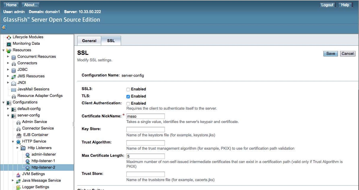
Click Save, and then restart glassfish. If logged on as the glassfish user, run the following command:
$ sudo service glassfishd restartIn a browser, access the SKCE web service on Port 8181, and ensure that it is using the newly created certificate.
For the FIDO Engine tests below to complete successfully, the main CA trust store for the JDK will need to be updated with your organization’s CA certificate. This can also be done with keytool:
$ keytool -import -trustcacerts -file lab-certs/root.pem -keystore $JAVA_HOME/jre/lib/security/cacerts
Test the FIDO Engine: Follow the testing instructions under Step 4 at the following URL: https://sourceforge.net/p/skce/wiki/Test%20SKCE%202.0%20Using%20a%20Client%20Program%20%28Build%20163%29/#4test-skcefido-engine.
There are additional tests on that web page to test the other cryptographic functions of the SKCE; however, only the FIDO Engine tests are critical for this build.
If the FIDO Engine tests are completed without errors, proceed to Section 6.3 to integrate the SKCE with the IdP. If any errors are encountered, the Glassfish log file (located at /usr/local/strongauth/glassfish4/glassfish/domains/domain1/logs/server.log) should contain messages to aid in troubleshooting.
6.3 How to Install and Configure the FIDO U2F Adapter for the IdP
To incorporate FIDO U2F authentication into a login flow at the IdP, some integration is needed to enable the IdP to call the SKCE APIs. In the lab build architecture, FIDO U2F authentication was integrated into a SAML IdP. PingFederate has a plugin architecture that enables the use of custom and third-party adapters in the authentication flow. StrongKey provides a PingFederate plugin to enable PingFederate IdPs (or AS) to support U2F authentication. This section describes the installation of the plugin on a PingFederate server. For details on how to integrate U2F authentication to a login flow, see Section 4.2.1.3.
The StrongKey plugin for PingFederate is delivered in a zip file containing documentation and all of the required program files.
To begin the installation process, upload the zip file to the PingFederate server where the StrongKey plugin will be installed, and unzip the files.
If Apache Ant is not already installed on the server, install it now by using the server’s package manager. For CentOS, this can be done by running the following command:
# yum install antOnce Apache Ant is installed, follow the “Installation” instructions in the StrongKey – Ping Federate FIDO IdP Adapter Installation Guide [C30], which consist of copying the plugin files to the required directories in the PingFederate installation, and running build.sh. If the script runs successfully, it will build the plugin using Ant and restart PingFederate.
Follow the steps in “Table 2: Configure the SKCE” in the Installation Guide. For this build, the app.json file needs to be copied to a browser-accessible location on the PingFederate server where the plugin is being installed. In the lab, we placed it under the following location:
/usr/share/pingfederate-8.3.2/pingfederate/server/default/conf/template/assets/scripts
This enables the app.json to be accessed at the URL https://idp1.spsd.msso:9031/assets/scripts/app.json. Note that Steps 4 and 5 in Table 2 of the Installation Guide are required only if the SKCE is using the default self-signed certificate; if a trusted certificate was installed as described in Section 6.2, then those steps can be skipped.
Download the JQuery 2.2.0 library at the URL below, and save it to the scripts folder referenced above: https://code.jquery.com/jquery-2.2.0.min.js.
Follow the steps in “Table 3: Configure the Ping Federate Instance” in the Installation Guide. Importing the SKCE self-signed certificate is not required if a trusted certificate was created. Installation of the JCE unlimited policy was described in the PingFederate installation instructions in Section 3, so that too can be skipped at this point, if it has already been done. Steps 7-9 should be completed in any case.
Follow the steps in “Table 4: Configuring the FIDO Adapter” in the Installation Guide. In Step 5, the Domain ID typically should be set to “1,” unless you have defined multiple domains in the SKCE. For the username and password, use the values configured earlier in install-skce.sh.
“Table 5: Ping Federate OAuth Configuration Steps” in the Installation Guide provides an example of how to incorporate U2F into a login flow, along with username/password form login, by creating a composite adapter that includes the login form and U2F adapters, and using a selector to activate the composite adapter whenever an OAuth authorization request includes the scope value “ldap.” Alternatively, the individual adapters can be called directly in an authentication policy. See Chapter 4 of the Installation Guide for additional examples of using U2F in authentication policies.
6.3.1 FIDO U2F Registration in Production
By default, the StrongKey Ping plugin enables the registration of U2F authenticators. In production, an authorized registration process should be established to provide adequate assurance in the binding of the authenticator to a claimed identity. If the FIDO adapter is accessible after single-factor password authentication, organizations may want to disable the registration functionality. See Section B.5 in Volume B of this guide for a discussion of FIDO enrollment.
7 Functional Tests
The MSSO architecture has a number of interoperating components, which can make troubleshooting difficult. This section describes tests than can be performed to validate that individual components are working as expected. If issues are encountered with the overall SSO flow, these tests may help identify the problem area.
7.1 Testing FIDO Authenticators
The FIDO Alliance implements a Functional Certification Program, in which products are evaluated for conformance to the UAF and U2F specifications. Purchasing FIDO-certified authenticators can help avoid potential authenticator implementation issues. Information on the certification program is available at https://fidoalliance.org/certification/, and the FIDO Alliance website also lists certified products.
Some resources are available to help troubleshoot individual authenticators:
The Yubico demonstration site provides an interface for testing registration and authentication with U2F authenticators: https://demo.yubico.com/u2f.
The Nok Nok Labs Gateway Tutorial Application supports testing of the registration, authentication, and transaction verification functions of FIDO UAF authenticators.
7.2 Testing FIDO Servers
The StrongKey SKCE documentation includes instructions on testing U2F authenticator registration, authentication, de-registration, and other functions. See Step 14 in Section 6.2.
To test the NNAS, Nok Nok Labs provides the OnRamp mobile application in the Google Play Store and the Apple App Store to test the server APIs with UAF authenticators.
7.3 Testing IdPs
If federated authentication is failing, the issue may lie at the IdP or the AS. The PingFederate server log (located by default under <pingfederate-directory>/log/server.log), on both ends, should provide relevant messages.
In some cases, it may be beneficial to look at the assertions being issued by the IdP and to check for the expected attributes. This could be done by integrating a demonstration application as a federation client and debugging the data returned in the assertion. For SAML, projects like SimpleSAMLphp (https://simplesamlphp.org/) provide an implementation that is easy to deploy. It is also possible to perform this testing without installing additional tools.
One method for SAML is to use Chrome Remote Debugging for Android devices: https://developers.google.com/web/tools/chrome-devtools/remote-debugging/.
By logging the authentication flow in the Network pane of Chrome’s developer tools, the SAML response can be extracted and viewed. The authentication flow with the SAML IdP configured in this practice guide consists of a series of calls to the SSO.ping URL at the IdP. Because the SAML POST binding is used, the final SSO.ping response includes an HTML form that submits the SAML response back to the AS. The SAML response can be found in an input element in the page content:
<input type="hidden" name="SAMLResponse"
value="PHNhbWxwOlJlc3BvbnNlIFZlcnNpb249IjIuMCIgSUQ9Iko1T2xNNlZxZW5lVnpBU2doSHlsakFLYlI
uOCIgSXNzdWVJbnN0YW50PSIyMDE3LTExLTEzVDEzOjQ5OjE3LjEwMFoiIEluUmVzcG9uc2VUbz0iS2RwMXVfZ
HFPMHlNX2Z0YWVldWJnRjlvMFBYIiBEZXN0aW5hdGlvbj0iaHR0cHM6Ly9pZG0uc2FuZGJveC5tb3Rvcm9sYXN
vbHV0aW9ucy5jb20vc3AvQUNTLnNhbWwyIiB4bWxuczpzYW1scD0idXJuOm9hc2lzOm5hbWVzOnRjOlNBTUw6M
i4wOnByb3RvY29sIj48c2FtbDpJc3N1ZXIgeG1sbnM6c2FtbD0idXJuOm9hc2lzOm5hbWVzOnRjOlNBTUw6Mi4
wOmFzc2VydGlvbiI+aWRwMS5zcHNkLm1zc288L3NhbWw6SXNzdWVyPjxkczpTaWduYXR1cmUgeG1sbnM6ZHM9I
mh0dHA6Ly93d3cudzMub3JnLzIwMDAvMDkveG1sZHNpZyMiPgo8ZHM6U2lnbmVkSW5mbz4KPGRzOkNhbm9uaWN
hbGl6YXRpb25NZXRob2QgQWxnb3JpdGhtPSJodHRwOi8vd3d3LnczLm9yZy8yMDAxLzEwL3htbC1leGMtYzE0b
iMiLz4KPGRzOlNpZ25hdHVyZU1ldGhvZCBBbGdvcml0aG09Imh0dHA6Ly93d3cudzMub3JnLzIwMDEvMDQveG1
sZHNpZy1tb3JlI3JzYS1zaGEyNTYiLz4KPGRzOlJlZmVyZW5jZSBVUkk9IiNKNU9sTTZWcWVuZVZ6QVNnaEh5b
GpBS2JSLjgiPgo8ZHM6VHJhbnNmb3Jtcz4KPGRzOlRyYW5zZm9ybSBBbGdvcml0aG09Imh0dHA6Ly93d3cudzM
ub3JnLzIwMDAvMDkveG1sZHNpZyNlbnZlbG9wZWQtc2lnbmF0dXJlIi8+CjxkczpUcmFuc2Zvcm0gQWxnb3Jpd
GhtPSJodHRwOi8vd3d3LnczLm9yZy8yMDAxLzEwL3htbC1leGMtYzE0biMiLz4KPC9kczpUcmFuc2Zvcm1zPgo
8ZHM6RGlnZXN0TWV0aG9kIEFsZ29yaXRobT0iaHR0cDovL3d3dy53My5vcmcvMjAwMS8wNC94bWxlbmMjc2hhM
jU2Ii8+CjxkczpEaWdlc3RWYWx1ZT4xdlFpcUNVNmlZYTMzdlFtKzcxbEVsVm1pUUh6T2U5cytBTTdQYTk4Vlp
BPTwvZHM6RGlnZXN0VmFsdWU+CjwvZHM6UmVmZXJlbmNlPgo8L2RzOlNpZ25lZEluZm8+CjxkczpTaWduYXR1c
mVWYWx1ZT4KTHpSbUJhclk2bndGS3ZydjdTL29WYWNJSWRJRUY4eUloV0JXT0NHZ3pyMWtONGVzVi9CU3lLQ1N
XYjhKU1h3QzhWRHNNUnRXOENMNQpVRFV0NTV1OXRCa05Wanh2NWR0NStOYXQ5eWtmdnhXbU9kcGVJVTBzMXNuM
UJHdytkOTRoZUlCYVdJWE1ZOVlRaDlnV3Q2Sll0OVFhCmRGdDZrRUY1S1NDS1FBQVNlbTEyT2xLV29GK2JSbG1
HNGVsbTVMTTh1N0E3Wi9hRnZ1cDNDNmV5ZEpwK1IxaStaK0F6NHlXdmMvNmEKYnlLMTBPZ05pLzBibnprazd3L
0psdHk0ZlVEcVd6bXJyRFpwSEJ4ZkFMVW5UV2RPVDVJeko3bmpMQWtBYVN0NDYwWjUyblpBOGFBYgpVbzA4T0t
EYnZVaS9UZ2xTcUZjcDJSYStCaE9DbUR3OWJvTG9udz09CjwvZHM6U2lnbmF0dXJlVmFsdWU+CjwvZHM6U2lnb
mF0dXJlPjxzYW1scDpTdGF0dXM+PHNhbWxwOlN0YXR1c0NvZGUgVmFsdWU9InVybjpvYXNpczpuYW1lczp0Yzp
TQU1MOjIuMDpzdGF0dXM6U3VjY2VzcyIvPjwvc2FtbHA6U3RhdHVzPjxzYW1sOkFzc2VydGlvbiBJRD0iSF9tL
ldIR29VUVBELjNjVlA0MVhDVVh4YkdLIiBJc3N1ZUluc3RhbnQ9IjIwMTctMTEtMTNUMTM6NDk6MTcuMTU1WiI
gVmVyc2lvbj0iMi4wIiB4bWxuczpzYW1sPSJ1cm46b2FzaXM6bmFtZXM6dGM6U0FNTDoyLjA6YXNzZXJ0aW9uI
j48c2FtbDpJc3N1ZXI+aWRwMS5zcHNkLm1zc288L3NhbWw6SXNzdWVyPjxzYW1sOlN1YmplY3Q+PHNhbWw6TmF
tZUlEIEZvcm1hdD0idXJuOm9hc2lzOm5hbWVzOnRjOlNBTUw6MS4xOm5hbWVpZC1mb3JtYXQ6dW5zcGVjaWZpZ
WQiPnVuY2NvZXRlc3Q0PC9zYW1sOk5hbWVJRD48c2FtbDpTdWJqZWN0Q29uZmlybWF0aW9uIE1ldGhvZD0idXJ
uOm9hc2lzOm5hbWVzOnRjOlNBTUw6Mi4wOmNtOmJlYXJlciI+PHNhbWw6U3ViamVjdENvbmZpcm1hdGlvbkRhd
GEgUmVjaXBpZW50PSJodHRwczovL2lkbS5zYW5kYm94Lm1vdG9yb2xhc29sdXRpb25zLmNvbS9zcC9BQ1Muc2F
tbDIiIE5vdE9uT3JBZnRlcj0iMjAxNy0xMS0xM1QxMzo1NDoxNy4xNTVaIiBJblJlc3BvbnNlVG89IktkcDF1X
2RxTzB5TV9mdGFlZXViZ0Y5bzBQWCIvPjwvc2FtbDpTdWJqZWN0Q29uZmlybWF0aW9uPjwvc2FtbDpTdWJqZWN
0PjxzYW1sOkNvbmRpdGlvbnMgTm90QmVmb3JlPSIyMDE3LTExLTEzVDEzOjQ0OjE3LjE1NVoiIE5vdE9uT3JBZ
nRlcj0iMjAxNy0xMS0xM1QxMzo1NDoxNy4xNTVaIj48c2FtbDpBdWRpZW5jZVJlc3RyaWN0aW9uPjxzYW1sOkF
1ZGllbmNlPmN0b1BpbmdGZWRfZW50aXR5SUQ8L3NhbWw6QXVkaWVuY2U+PC9zYW1sOkF1ZGllbmNlUmVzdHJpY
3Rpb24+PC9zYW1sOkNvbmRpdGlvbnM+PHNhbWw6QXV0aG5TdGF0ZW1lbnQgU2Vzc2lvbkluZGV4PSJIX20uV0h
Hb1VRUEQuM2NWUDQxWENVWHhiR0siIEF1dGhuSW5zdGFudD0iMjAxNy0xMS0xM1QxMzo0OToxNy4xNTNaIj48c
2FtbDpBdXRobkNvbnRleHQ+PHNhbWw6QXV0aG5Db250ZXh0Q2xhc3NSZWY+dXJuOm9hc2lzOm5hbWVzOnRjOlN
BTUw6Mi4wOmFjOmNsYXNzZXM6dW5zcGVjaWZpZWQ8L3NhbWw6QXV0aG5Db250ZXh0Q2xhc3NSZWY+PC9zYW1sO
kF1dGhuQ29udGV4dD48L3NhbWw6QXV0aG5TdGF0ZW1lbnQ+PHNhbWw6QXR0cmlidXRlU3RhdGVtZW50PjxzYW1
sOkF0dHJpYnV0ZSBOYW1lPSJ1aWQiIE5hbWVGb3JtYXQ9InVybjpvYXNpczpuYW1lczp0YzpTQU1MOjIuMDphd
HRybmFtZS1mb3JtYXQ6YmFzaWMiPjxzYW1sOkF0dHJpYnV0ZVZhbHVlIHhzaTp0eXBlPSJ4czpzdHJpbmciIHh
tbG5zOnhzPSJodHRwOi8vd3d3LnczLm9yZy8yMDAxL1hNTFNjaGVtYSIgeG1sbnM6eHNpPSJodHRwOi8vd3d3L
nczLm9yZy8yMDAxL1hNTFNjaGVtYS1pbnN0YW5jZSI+dW5jY29ldGVzdDQ8L3NhbWw6QXR0cmlidXRlVmFsdWU
+PC9zYW1sOkF0dHJpYnV0ZT48c2FtbDpBdHRyaWJ1dGUgTmFtZT0ibWFpbCIgTmFtZUZvcm1hdD0idXJuOm9hc
2lzOm5hbWVzOnRjOlNBTUw6Mi4wOmF0dHJuYW1lLWZvcm1hdDpiYXNpYyI+PHNhbWw6QXR0cmlidXRlVmFsdWU
geHNpOnR5cGU9InhzOnN0cmluZyIgeG1sbnM6eHM9Imh0dHA6Ly93d3cudzMub3JnLzIwMDEvWE1MU2NoZW1hI
iB4bWxuczp4c2k9Imh0dHA6Ly93d3cudzMub3JnLzIwMDEvWE1MU2NoZW1hLWluc3RhbmNlIj51bmNjb2V0ZXN
0NDwvc2FtbDpBdHRyaWJ1dGVWYWx1ZT48L3NhbWw6QXR0cmlidXRlPjwvc2FtbDpBdHRyaWJ1dGVTdGF0ZW1lb
nQ+PC9zYW1sOkFzc2VydGlvbj48L3NhbWxwOlJlc3BvbnNlPg=="/>
The “value” string is the base64-encoded SAML response. A few lines of Python can get the SAML response into a readable format. In this example, the value above has been saved to a file called samlresp.txt:
$ python
Python 2.7.10 (default, Feb 7 2017, 00:08:15)
[GCC 4.2.1 Compatible Apple LLVM 8.0.0 (clang-800.0.34)] on darwin
Type "help", "copyright", "credits" or "license" for more information.
>>> import base64
>>> import xml.dom.minidom
>>> respFile = open("samlresp.txt", "r")
>>> respStr = base64.b64decode(respFile.read())
>>> respXml = xml.dom.minidom.parseString(respStr)
>>> print(respXml.toprettyxml())
<?xml version="1.0" ?>
<samlp:Response Destination="https://idm.sandbox.motorolasolutions.com/sp/ACS.saml2" ID="J5OlM6VqeneVzASghHyljAKbR.8" InResponseTo="Kdp1u_dqO0yM_ftaeeubgF9o0PX" IssueInstant="2017-11-13T13:49:17.100Z" Version="2.0" xmlns:samlp="urn:oasis:names:tc:SAML:2.0:protocol">
    <saml:Issuer xmlns:saml="urn:oasis:names:tc:SAML:2.0:assertion">idp1.spsd.msso</saml:Issuer>
    <ds:Signature xmlns:ds="http://www.w3.org/2000/09/xmldsig#">
            <ds:SignedInfo>
                    <ds:CanonicalizationMethod Algorithm="http://www.w3.org/2001/10/xml-exc-c14n#"/>


                    <ds:SignatureMethod Algorithm="http://www.w3.org/2001/04/xmldsig-more#rsa-sha256"/>
                    <ds:Reference URI="#J5OlM6VqeneVzASghHyljAKbR.8">
                            <ds:Transforms>
                                    <ds:Transform Algorithm="http://www.w3.org/2000/09/xmldsig#enveloped-signature"/>
                                    <ds:Transform Algorithm="http://www.w3.org/2001/10/xml-exc-c14n#"/>
                            </ds:Transforms>
                            <ds:DigestMethod Algorithm="http://www.w3.org/2001/04/xmlenc#sha256"/>
<ds:DigestValue>1vQiqCU6iYa33vQm+71lElVmiQHzOe9s+AM7Pa98VZA=</ds:DigestValue>
                    </ds:Reference>
            </ds:SignedInfo>
            <ds:SignatureValue>
LzRmBarY6nwFKvrv7S/oVacIIdIEF8yIhWBWOCGgzr1kN4esV/BSyKCSWb8JSXwC8VDsMRtW8CL5
UDUt55u9tBkNVjxv5dt5+Nat9ykfvxWmOdpeIU0s1sn1BGw+d94heIBaWIXMY9YQh9gWt6JYt9Qa
dFt6kEF5KSCKQAASem12OlKWoF+bRlmG4elm5LM8u7A7Z/aFvup3C6eydJp+R1i+Z+Az4yWvc/6a
byK10OgNi/0bnzkk7w/Jlty4fUDqWzmrrDZpHBxfALUnTWdOT5IzJ7njLAkAaSt460Z52nZA8aAb
Uo08OKDbvUi/TglSqFcp2Ra+BhOCmDw9boLonw==
</ds:SignatureValue>
    </ds:Signature>
    <samlp:Status>
            <samlp:StatusCode Value="urn:oasis:names:tc:SAML:2.0:status:Success"/>
    </samlp:Status>
    <saml:Assertion ID="H_m.WHGoUQPD.3cVP41XCUXxbGK" IssueInstant="2017-11-13T13:49:17.155Z" Version="2.0" xmlns:saml="urn:oasis:names:tc:SAML:2.0:assertion">
            <saml:Issuer>idp1.spsd.msso</saml:Issuer>
            <saml:Subject>
                    <saml:NameID Format="urn:oasis:names:tc:SAML:1.1:nameid-format:unspecified">unccoetest4</saml:NameID>
                    <saml:SubjectConfirmation Method="urn:oasis:names:tc:SAML:2.0:cm:bearer">
                            <saml:SubjectConfirmationData InResponseTo="Kdp1u_dqO0yM_ftaeeubgF9o0PX" NotOnOrAfter="2017-11-13T13:54:17.155Z" Recipient="https://idm.sandbox.motorolasolutions.com/sp/ACS.saml2"/>
                    </saml:SubjectConfirmation>
            </saml:Subject>
            <saml:Conditions NotBefore="2017-11-13T13:44:17.155Z" NotOnOrAfter="2017-11-13T13:54:17.155Z">
                    <saml:AudienceRestriction>
<saml:Audience>ctoPingFed_entityID</saml:Audience>
                    </saml:AudienceRestriction>
            </saml:Conditions>
            <saml:AuthnStatement AuthnInstant="2017-11-13T13:49:17.153Z" SessionIndex="H_m.WHGoUQPD.3cVP41XCUXxbGK">
                    <saml:AuthnContext>
<saml:AuthnContextClassRef>urn:oasis:names:tc:SAML:2.0:ac:classes:unspecified</saml:AuthnContextClassRef>
                    </saml:AuthnContext>
            </saml:AuthnStatement>
            <saml:AttributeStatement>
                    <saml:Attribute Name="uid" NameFormat="urn:oasis:names:tc:SAML:2.0:attrname-format:basic">
                            <saml:AttributeValue xmlns:xs="http://www.w3.org/2001/XMLSchema" xmlns:xsi="http://www.w3.org/2001/XMLSchema-instance" xsi:type="xs:string">unccoetest4</saml:AttributeValue>
                    </saml:Attribute>
                    <saml:Attribute Name="mail" NameFormat="urn:oasis:names:tc:SAML:2.0:attrname-format:basic">
                            <saml:AttributeValue xmlns:xs="http://www.w3.org/2001/XMLSchema" xmlns:xsi="http://www.w3.org/2001/XMLSchema-instance" xsi:type="xs:string">unccoetest4</saml:AttributeValue>
                    </saml:Attribute>
            </saml:AttributeStatement>
    </saml:Assertion>
</samlp:Response>

>>>
In the above example, two attributes, uid and mail, are asserted, but the mail attribute does not contain a valid email address.
For OIDC, because the ID Token is retrieved over a back-channel connection between the RP and the IdP, it cannot be observed in browser traffic. As with SAML, creating a test application is one method of testing, but manual testing is also possible by using a few software tools:
Register an OIDC client with a client secret and a redirect URI that points to a nonexistent server. A redirect URI value like
https://127.0.0.1/test-urlwill work, assuming that you do not have a web server running on your machine. In a desktop browser, submit an authentication request with a URL like the one listed below:https://op1.lpsd.msso:9031/as/authorization.oauth2?client_id=marktest&response_type=code&scope=openid%20address%20test%20phone%20openid%20profile%20name%20email
Replace the server name and client ID with the correct values for your environment; also make sure that the scope parameter includes
openidand any other expected scopes. Authenticate to the IdP. In this case, because the FIDO UAF adapter is in use but is being accessed through a desktop browser, it initiates an OOB authentication, which can be completed on the mobile device. Once authentication is completed, the browser will attempt to access the redirect URL, which will result in a connection error because no web server is running on localhost. However, the authorization code can be extracted from the URL:https://127.0.0.1/test-url?code=Iv-pND_3o7_aJ5nFMcD-WbrVENrW7w5V75Cupx9G
The authorization code can be submitted to the IdP’s token endpoint in a POST to obtain the ID Token. There are numerous ways to do this. Postman is a simple graphical-user-interface tool for testing APIs and can be used to submit the request: https://www.getpostman.com.
Figure 7‑1 shows Postman being used to retrieve an ID Token. A POST request is submitted to the OIDC IdP’s token endpoint; by default, the token endpoint URL is the base URL, followed by /as/token.oauth2. The authorization code is included as a query parameter. The client ID and client secret are used as the HTTP basic authorization username and password.
Figure 7‑1 Using Postman to Obtain the ID Token
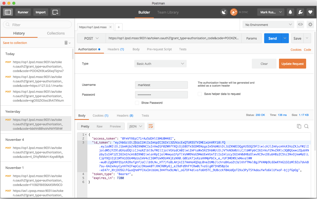
The response body is a JSON object, including the ID Token as well as an access token that can be used to access the userinfo endpoint. As with the SAML assertion, a few lines of Python can render the ID Token (which is a JWT) into a readable format:
$ python
Python 2.7.10 (default, Feb 7 2017, 00:08:15)
[GCC 4.2.1 Compatible Apple LLVM 8.0.0 (clang-800.0.34)] on darwin
Type "help", "copyright", "credits" or "license" for more information.
>>> import jwt
>>> import json
>>> idTokenStr = "eyJhbGciOiJSUzI1NiIsImtpZCI6Ikl3ZUVzcExQTUR5STVIME1xUnVRY18ifQ.eyJzdWIiOiJ1bmNjb2V0ZXN0NCIsInVwZGF0ZWRfYXQiOjE0OTk5ODM5NzgsIm5hbWUiOiJUZXN0IDQgVU5DQ29FIiwicHJlZmVycmVkX3VzZXJuYW1lIjoidW5jY29ldGVzdDQiLCJnaXZlbl9uYW1lIjoiVGVzdCA0IiwiZmFtaWx5X25hbWUiOiJVTkNDb0UiLCJlbWFpbCI6InVuY2NvZXRlc3Q0QGxwc2QubXNzbyIsImF1ZCI6Im1hcmt0ZXN0IiwianRpIjoiMmwya1FpTlVsNW9VaG5MeUEwVUxTZiIsImlzcyI6Imh0dHBzOlwvXC9vcDEubHBzZC5tc3NvOjkwMzEiLCJpYXQiOjE1MTA1ODU4MzUsImV4cCI6MTUxMDU4NjEzNX0.G0EzK7jxXzsHHMpPbCk_e_rUF3MEW9JxMxvzlWW-wu0i2gQHRPZUytR2RxfghfJaCilb9LNv_HT7Jfa8LAHjkII7AmHa4QDqL0ne2UMbJlchraBKuoZt3zlKhfTMxl0gJPVAMp9L6DwXYmG1D2zMl92s7dvkB7su-6A2xAxyCynH7mIFwpCaJ3Nswk0TiXNCR0Ry6j_eJ9dFd9hFYCRw0LTvzGig073h058pIe-xE47r_XhjDD5GiFGuoQhmPfCKxImibUmL3H4fhx9LMel_oG7DF4divsfo6H5TC_9UBccKf0AUdQoT2Kx3PyTSYAdouYwfo6klUYxoF-bjjfGpOg"
>>> idToken = jwt.decode(idTokenStr, verify=False)
>>> print json.dumps(idToken, indent=4)
{
    "family_name": "UNCCoE",
    "aud": "marktest",
    "sub": "unccoetest4",
    "iss": "https://op1.lpsd.msso:9031",
    "preferred_username": "unccoetest4",
    "updated_at": 1499983978,
    "jti": "2l2kQiNUl5oUhnLyA0ULSf",
    "given_name": "Test 4",
    "exp": 1510586135,
    "iat": 1510585835,
    "email": "[email protected]",
    "name": "Test 4 UNCCoE"
}
>>>
This merely decodes the claims in the JWT without verifying the signature. If there is an issue with signature validation or trust in the signing key, these errors will be reported in the PingFederate server log.
7.4 Testing the AS
One simple step that can help identify problems at the AS is turning on the authorization prompts. This can be done on a per-client basis by deselecting the BYPASS AUTHORIZATION APPROVAL setting on the client configuration page in the OAuth Settings section in the AS console. If the authorization prompt is displayed (Figure 7‑2), this demonstrates that authentication has succeeded, and the list of scopes being requested by the client is displayed and can be verified.
Figure 7‑2 Authorization Prompt
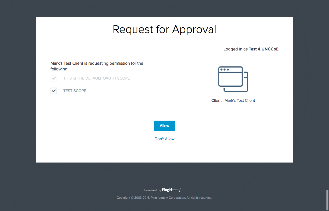
It is also possible to manually obtain an access token by using the same procedure that was used in the previous section to obtain an ID Token; the only
difference is that an OAuth request typically would not include the openid scope. If the issued access token is a JWT, it can be analyzed using Python as
described above.
If the token is not a JWT (i.e., a Reference Token management scheme is in use), the access token can be submitted to the AS’s introspection endpoint as specified in RFC 7662 [C31]. The default location of the introspection endpoint for PingFederate is the base URL, followed by /as/introspect.oauth2. The request is submitted as a POST, with the access token in a query parameter called token. Basic authentication can be used with the client ID and secret as a username and password. The client must be authorized to call the introspection endpoint by selecting Access Token Validation (Client is a Resource Server) under Allowed Grant Types in the client configuration on the AS.
Figure 7‑3 shows a token introspection request and response in Postman.
Figure 7‑3 Token Introspection Request and Response
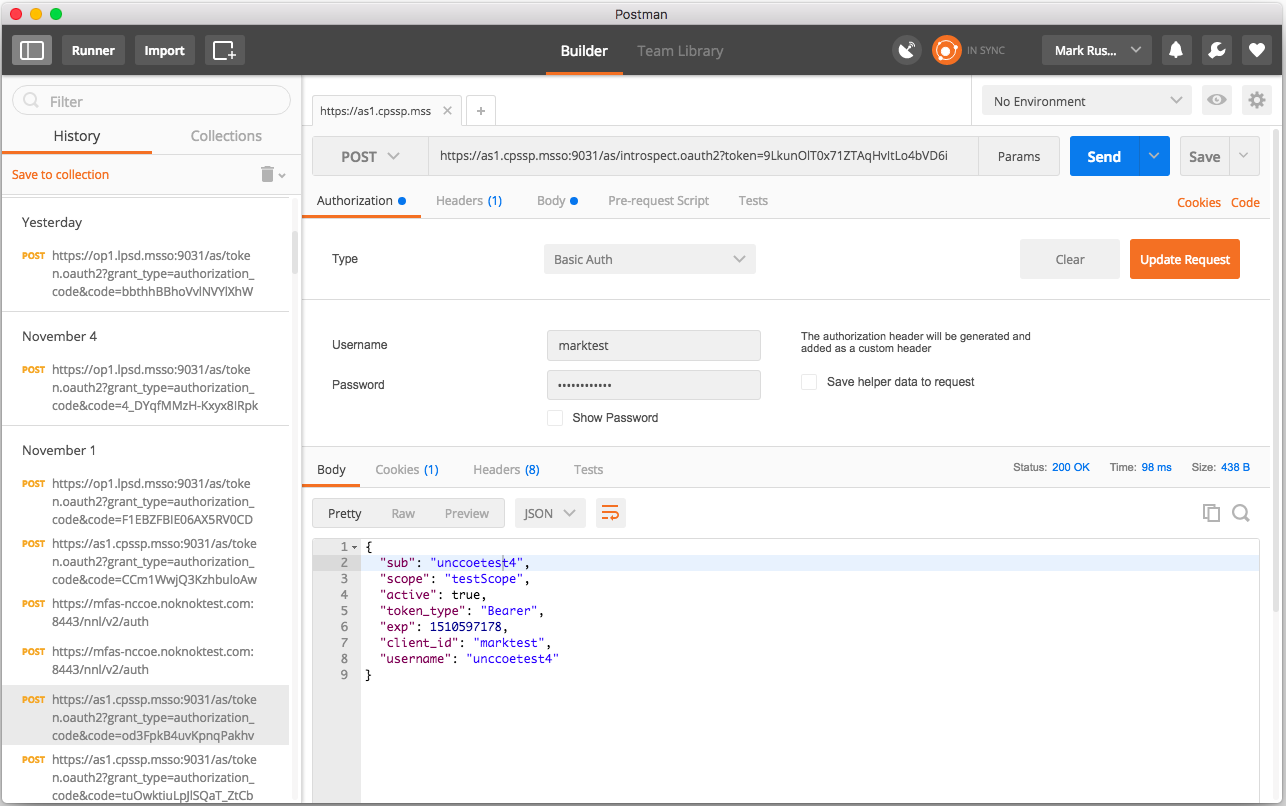
7.5 Testing the Application
One last potential problem area in this SSO architecture is the back-end application, which must accept and validate access tokens. Troubleshooting methods there will depend on the design of the application. Building robust instrumentation and error reporting into RP applications will help identify problems. If the application validates JWT access tokens, then establishing and maintaining trust in the AS’s signing certificate, including maintenance when the certificate is replaced, is essential to avoid validation problems. Clock synchronization between the AS and the RP is also important; a time difference of five minutes or more can cause validation errors as well.