NIST SPECIAL PUBLICATION 1800-7B
Situational Awareness For Electric Utilities
Volume B:
Approach, Architecture, and Security Characteristics
Jim McCarthy
National Cybersecurity Center of Excellence
National Institute of Standards and Technology
Otis Alexander
Sallie Edwards
Don Faatz
Chris Peloquin
Susan Symington
Andre Thibault
John Wiltberger
Karen Viani
The MITRE Corporation
McLean, VA
August 2019
This publication is available free of charge from: https://doi.org/10.6028/NIST.SP.1800-7
The first draft of this publication is available free of charge from: https://www.nccoe.nist.gov/sites/default/files/library/sp1800/es-sa-nist-sp1800-7-draft.pdf

DISCLAIMER
Certain commercial entities, equipment, products, or materials may be identified in this document in order to describe an experimental procedure or concept adequately. Such identification is not intended to imply recommendation or endorsement by NIST or NCCoE, nor is it intended to imply that the entities, equipment, products, or materials are necessarily the best available for the purpose.
National Institute of Standards and Technology Special Publication 1800-7B, Natl. Inst. Stand. Technol. Spec. Publ. 1800-7B, 87 pages, (August 2019), CODEN: NSPUE2
FEEDBACK
As a private-public partnership, we are always seeking feedback on our Practice Guides. We are particularly interested in seeing how businesses apply NCCoE reference designs in the real world. If you have implemented the reference design, or have questions about applying it in your environment, please email us at energy_nccoe@nist.gov.
All comments are subject to release under the Freedom of Information Act (FOIA).
NATIONAL CYBERSECURITY CENTER OF EXCELLENCE
The National Cybersecurity Center of Excellence (NCCoE), a part of the National Institute of Standards and Technology (NIST), is a collaborative hub where industry organizations, government agencies, and academic institutions work together to address businesses’ most pressing cybersecurity issues. This public-private partnership enables the creation of practical cybersecurity solutions for specific industries, as well as for broad, cross-sector technology challenges. Through consortia under Cooperative Research and Development Agreements (CRADAs), including technology partners — from Fortune 50 market leaders to smaller companies specializing in IT security — the NCCoE applies standards and best practices to develop modular, easily adaptable example cybersecurity solutions using commercially available technology. The NCCoE documents these example solutions in the NIST Special Publication 1800 series, which maps capabilities to the NIST Cybersecurity Framework and details the steps needed for another entity to recreate the example solution. The NCCoE was established in 2012 by NIST in partnership with the State of Maryland and Montgomery County, Md.
To learn more about the NCCoE, visit https://www.nccoe.nist.gov/.
NIST CYBERSECURITY PRACTICE GUIDES
NIST Cybersecurity Practice Guides (Special Publication Series 1800) target specific cybersecurity challenges in the public and private sectors. They are practical, user-friendly guides that facilitate the adoption of standards-based approaches to cybersecurity. They show members of the information security community how to implement example solutions that help them align more easily with relevant standards and best practices and provide users with the materials lists, configuration files, and other information they need to implement a similar approach.
The documents in this series describe example implementations of cybersecurity practices that businesses and other organizations may voluntarily adopt. These documents do not describe regulations or mandatory practices, nor do they carry statutory authority.
ABSTRACT
Through direct dialogue between NCCoE staff and members of the energy sector (composed mainly of electric power companies and those who provide equipment and/or services to them) it became clear that energy companies need to create and maintain a high level of visibility into their operating environments to ensure the security of their operational resources (operational technology [OT]), including industrial control systems (ICS), buildings, and plant equipment. However, energy companies, as well as all other utilities with similar infrastructure and situational awareness challenges, also need insight into their corporate or information technology (IT) systems and physical access control systems (PACS). The convergence of data across these three often self-contained silos (OT, IT, and PACS) can better protect power generation, transmission, and distribution.
Real-time or near real-time situational awareness is a key element in ensuring this visibility across all resources. Situational awareness, as defined in this use case, is the ability to comprehensively identify and correlate anomalous conditions pertaining to ICS, IT resources, and access to buildings, facilities, and other business mission-essential resources. For energy companies, having mechanisms to capture, transmit, view, analyze, and store real-time or near-real-time data from ICS and related networking equipment provides energy companies with the information needed to deter, identify, respond to, and mitigate cyber attacks against their assets.
With such mechanisms in place, electric utility owners and operators can more readily detect anomalous conditions, take appropriate actions to remedy them, investigate the chain of events that led to the anomalies, and share findings with other energy companies. Obtaining real-time and near-real-time data from networks also has the benefit of helping demonstrate compliance with information security standards. This NCCoE project’s goal is ultimately to improve the security of OT through situational awareness.
This NIST Cybersecurity Practice Guide describes our collaborative efforts with technology providers and energy sector stakeholders to address the security challenges that energy providers face in deploying a comprehensive situational awareness capability. It offers a technical approach to meeting the challenge and also incorporates a business value mind-set by identifying the strategic considerations involved in implementing new technologies. The guide provides a modular, end-to-end example solution that can be tailored and implemented by energy providers of varying sizes and sophistication. It shows energy providers how we met the challenge by using open-source and commercially available tools and technologies that are consistent with cybersecurity standards. The use case is based on an everyday business operational scenario that provides the underlying impetus for the functionality presented in the guide. Test cases were defined with industry participation to provide multiple examples of the capabilities necessary to provide situational awareness.
While the example solution was demonstrated with a certain suite of products, the guide does not endorse these products. Instead, it presents the characteristics and capabilities that an organizationʼs security experts can use to identify similar standards-based products that can be integrated quickly and cost effectively with an energy provider’s existing tools and infrastructure.
KEYWORDS
correlated events; cybersecurity; energy sector; information technology; operational technology; physical access control systems; security information and event management; situational awareness
ACKNOWLEDGMENTS
We are grateful to the following individuals for their generous contributions of expertise and time.
Name |
Organization |
Robert Lee |
Dragos |
Justin Cavinee |
Dragos |
Jon Lavender |
Dragos |
Steve Roberts |
Hewlett Packard Enterprise |
Bruce Oehler |
Hewlett Packard Enterprise |
Gil Kroyzer |
ICS2 |
Gregory Ravikovich |
ICS2 |
Robert Bell |
ICS2 |
Fred Hintermeister |
NERC |
Paul J. Geraci |
OSIsoft |
Mark McCoy |
OSIsoft |
Stephen J. Sarnecki |
OSIsoft |
Paul Strasser |
PPC |
Matt McDonald |
PPC |
Steve Sage |
PPC |
T.J. Roe |
Radiflow |
Ayal Vogel |
Radiflow |
Dario Lobozzo |
Radiflow |
Dave Barnard |
RS2 |
Ben Smith |
RSA |
Tarik Williams |
RSA, a Dell Technologies business |
David Perodin |
RSA, a Dell Technologies business |
George Wrenn |
Schneider Electric |
Michael Pyle |
Schneider Electric |
AJ Nicolosi |
Siemens |
Jeff Foley |
Siemens |
Bill Johnson |
TDi Technologies |
Pam Johnson |
TDi |
Clyde Poole |
TDi |
Eric Chapman |
University of Maryland, College Park |
David S. Shaughnessy |
University of Maryland, College Park |
Don Hill |
University of Maryland, College Park |
Mary-Ann Ibeziako |
University of Maryland, College Park |
Damian Griffe |
University of Maryland, College Park |
Mark Alexander |
University of Maryland, College Park |
Nollaig Heffernan |
Waratek |
James Lee |
Waratek |
John Matthew Holt |
Waratek |
Andrew Ginter |
Waterfall |
Courtney Schneider |
Waterfall |
Tim Pierce |
Waterfall |
Kori Fisk |
The MITRE Corporation |
Tania Copper |
The MITRE Corporation |
The Technology Partners/Collaborators who participated in this build submitted their capabilities in response to a notice in the Federal Register. Respondents with relevant capabilities or product components were invited to sign a Cooperative Research and Development Agreement (CRADA) with NIST, allowing them to participate in a consortium to build this example solution. We worked with:
| Technology Partner/Collaborator | Build Involvement |
|---|---|
| Dragos | CyberLens |
| Hewlett Packard Enterprise* | ArcSight |
| ICS2 | OnGuard |
| OSIsoft | Pi Historian |
| Radiflow | iSIM |
| RS2 Technologies | Access It!, Door Controller |
| RSA, a Dell Technologies business | Archer Security Operations Management |
| Schneider Electric | Tofino Firewall |
| Siemens | RUGGEDCOM CROSSBOW |
| TDi Technologies | ConsoleWorks |
| Waratek | Waratek Runtime Application Protection |
| Waterfall Security Solutions | Unidirectional Security Gateway, Secure Bypass |
*Please note: Hewlett Packard Enterprise in this project is now Micro Focus Government Solutions, which acquired the suite of products and solutions used by the NCCoE in this build.
The NCCoE also wishes to acknowledge the special contributions of the University of Maryland for providing us with a real-world setting for the situational awareness build; Project Performance Company for its dedication in assisting the NCCoE with the very challenging and complex integration in this build; and the NCCoE Energy Provider Community for its patience, support, and guidance throughout the life cycle of this project.
List of Figures
Figure 4-1 High-Level Example Solution Architecture
Figure 4-2 Network Connections Color Code
Figure 4-3 Monitoring, Data Collection, and Analysis Example Solution
Figure 4-4 Operations Monitoring and Data Collection Lab Build Architecture
Figure 4-5 Enterprise Data Aggregation and Analysis Lab Build Architecture
Figure 4-6 Remote Management Example Solution
Figure 4-7 Operations Remote Management Lab Build Architecture
Figure 4-8 Enterprise Remote Management Lab Build Architecture
Figure 5-1 Monitoring/Data Collection Subarchitecture Depicted with Generic Component Names
Figure 5-2 Data Aggregation/Analysis Subarchitecture Using Generic Component Names
Figure 5-3 Monitoring/Data Collection Management Architecture Depicted Using Generic Component Names
List of Tables
Table 3-1 Security Characteristics and Controls Mapping – NIST Cybersecurity Framework
Table 3-2 Products and Technologies
Table 3-3 Situational Awareness Test Cases
Table 6-1 Functional Test Plan
Table 6-2 Functional Evaluation Requirements
1. Summary
Situational awareness (SA) is “the perception of elements in the environment within a volume of time and space, the comprehension of their meaning, and the projection of their status in the near future” [1]. The intent of SA is to know what is happening around you and how it might affect your activities. For electricity utilities, this means understanding what is happening in the environment that might affect delivery of electricity to customers. Traditionally, this has involved knowing the operating status of generation, transmission, and distribution systems, as well as physical challenges such as weather and readiness, to facilitate response to outages. As computers and networks have been incorporated in grid operations, awareness of the cyber situation is becoming increasingly important to ensuring that “the lights stay on.”
The National Cybersecurity Center of Excellence (NCCoE) met with energy sector stakeholders to understand key cybersecurity issues impacting operations. The feedback emphasized a more efficient means of comprehensively detecting potential cybersecurity incidents directed at their operational technology (OT) or industrial control systems (ICS), information technology (IT) or corporate networks, and their physical facilities such as substations and corporate offices.
The NCCoE’s example solution provides a converged and correlated view of OT, IT, and physical access resources. In our reference design, we collect sensor data from these resources and provide alerts to a platform that produces actionable information.
This example solution is packaged as a “how to” guide that demonstrates how to implement standards-based cybersecurity technologies in the real world based on risk analysis and regulatory requirements. The guide might help the energy industry gain efficiencies in SA while saving research and proof-of-concept costs.
1.1. The Challenge
Energy companies rely on OT to control the generation, transmission, and distribution of power. While there are a number of useful products on the market for monitoring enterprise networks for possible security events, these products tend to be imperfect fits for the unusual requirements of control system networks. ICS and IT devices were designed with different purposes in mind. Attempting to use IT security applications for ICS, although in many cases useful, still does not properly account for the availability requirements of ICS networks. A network monitoring solution that is tailored to the needs of control systems would reduce security blind spots and provide real-time SA, that is, provide notification of events as they occur.
To improve overall SA, energy companies need mechanisms to capture, transmit, view, analyze, and store real-time or near-real-time data from ICS and related networking equipment. With such mechanisms in place, electric utility owners and operators can more readily detect anomalous conditions, take appropriate actions to remedy them, investigate the chain of events that led to the anomalies, and share findings with other energy companies. Obtaining real-time or near-real-time data from networks also helps organizations be compliance with information security standards or regulations, particularly those that require specific event log information.
There is a definite need to improve a utility’s ability to detect cyber-related security breaches or anomalous behavior, in real or near real time. The ability to do this will result in earlier detection of cybersecurity incidents and potentially reduce the severity of the impact of these incidents within a utility’s operational infrastructure. Energy sector stakeholders noted that a robust situational awareness solution also must be able to alert for both individual and correlated events or incidents. To address these needs, we created a scenario in which a technician dispatcher notices that a substation relay has tripped and begins to investigate the cause. The technician uses a single software interface that monitors system buses, displays an outage map, correlates operational network connections to the bus and outage maps, and indexes operational network and physical security device logs. The technician begins the investigation by querying network logs to determine whether any ICS devices received commands that might have caused the trip. If the answer is yes, then, using the same interface, the technician can automatically examine logs of the most recent commands and network traffic sent to the relevant devices. This information allows the technician to effectively extend the investigation to internal systems and users who communicated with the suspect devices.
To extend the scenario, an analyst on the IT network receives notification that a server is down. The analyst investigates across the network and is alerted of the tripped substation relay. Are the anomalies connected? Use of our SA solution could answer this question in addition to achieving the needs described above. Additional benefits of the solution are addressed in Section 1.4.
1.2. The Solution
This NIST Cybersecurity Practice Guide demonstrates how commercially available technologies can meet a utility’s need to provide comprehensive real-time or near-real-time SA.
The NCCoE laboratory houses an environment that simulates the common devices and technologies found in a utility such as IT and OT systems and physical access control systems (PACS). In this guide, we show how a utility can implement a converged alerting capability to provide a comprehensive view of cyber-related events and activities across silos by using multiple commercially available products. Furthermore, we identified products and capabilities that, when linked together, provide a converged and comprehensive platform that can alert utilities to potentially malicious activity.
The guide provides:
- a detailed example solution and capabilities that address security controls
- a demonstration of the approach that uses commercially available products
- how-to instructions for implementers and security engineers with instructions on integrating and configuring the example solution into their organization’s enterprise in a manner that achieves security goals with minimal impact on operational efficiency and expense
Commercial, standards-based products such as the ones we used are readily available and interoperable with existing IT infrastructure and investments. Our simulated environment is similar in breadth and diversity to the distributed networks of large organizations, which can include corporate and regional business offices, power generation plants, and substations, but not on the same scale of deployed assets as these large organizations.
This guide lists all the necessary components and provides installation, configuration, and integration information so that an energy company can replicate what we have built. The NCCoE does not endorse the suite of commercial products used in the reference design. These products were utilized after an open call to participate via the Federal Register. A utility’s security expert(s) should identify the standards-based products that will best integrate with the existing tools and systems already contained in the ICS and IT infrastructure. A business can adopt this solution or one that adheres to these guidelines in whole, or this guide can be used as a starting point for tailoring and implementing parts of a solution.
1.3. Risks
This practice guide addresses risk by using current industry standards, such as North American Electric Reliability Corporation Critical Infrastructure Protection (NERC CIP) V5, as well as taking into account risk considerations at both the operational and strategic levels.
At the strategic level, one might consider the cost of mitigating these risks and the potential return on investment in implementing a product (or multiple products). One might also want to assess if a converged SA platform can help enhance the productivity of employees, minimize impacts to the operating environment, and provide the ability to investigate incidents to mitigate future occurrences. This example solution addresses imminent operational security risks and incorporates strategic risk considerations.
Operationally, the lack of a converged SA platform, especially one with the ability to collect and correlate sensor data from all the silos, can increase both the risk of malicious cyber attacks being directed at an organization, or worse, the resulting damage that might ensue should such attacks go undetected. At a fundamental level, SA provides alerts to potential malicious behavior, which includes detection, prevention, and reporting mechanisms to ensure that proper remediation and investigation take place should these events occur.
Adopting any new technology, including this example SA solution, can introduce new risks to an enterprise. However, by aggregating sensor data from all the silos (OT, PACS, and IT), a utility can increase its ability to identify a potentially malicious event that might otherwise go undetected or unreported. The lack of ability to see across the silos and correlate event data yields a potential blind spot to the safe and secure operation of utilities’ most critical business assets.
1.4. Benefits
The NCCoE, in collaboration with our stakeholders in the energy sector, identified the need for a network monitoring solution specifically adapted to include ICS cybersecurity. The following are what we determined to be the key (but not exclusive) benefits of implementing this solution:
- improves a utility’s ability to detect cyber-related security breaches or anomalous behavior, likely resulting in earlier detection and less impact of critical incidents on energy delivery, thereby lowering overall business risk
- increases the probability that investigations of attacks or anomalous system behavior will reach successful conclusions
- improves accountability and traceability, leading to valuable operational lessons learned
- simplifies regulatory compliance by automating generation and collection of a variety of operational log data
2. How to Use This Guide
This NIST Cybersecurity Practice Guide demonstrates a standards-based reference design and provides users with the information they need to replicate the example solution. This reference design is modular and can be deployed in whole or in part.
This guide contains three volumes:
- NIST SP 1800-7A: Executive Summary
- NIST SP 1800-7B: Approach, Architecture, and Security Characteristics – what we built and why (you are here)
- NIST SP 1800-7C: How-To Guides – instructions for building the example solution
Depending on your role in your organization, you might use this guide in different ways:
Business decision makers, including chief security and technology officers, will be interested in the Executive Summary (NIST SP 1800-7A), which describes the following topics:
- challenges that sector organizations face in maintaining cross-silo situational awareness
- example solution built at the NCCoE
- benefits of adopting the example solution
Technology or security program managers who are concerned with how to identify, understand, assess, and mitigate risk will be interested in this part of the guide, NIST SP 1800-7B, which describes what we did and why. The following sections will be of particular interest:
- Section 3.4.1, Assessing Risk Posture, provides a description of the risk analysis we performed
- Section 3.4.2, Security Control Map, maps the security characteristics of this example solution to cybersecurity standards and best practices
You might share the Executive Summary, NIST SP 1800-7A, with your leadership team members to help them understand the importance of adopting standards-based SA for electric utilities.
IT professionals who want to implement an approach like this will find the whole practice guide useful. You can use the How-To portion of the guide, NIST SP 1800-7C, to replicate all or parts of the build created in our lab. The How-To guide provides specific product installation, configuration, and integration instructions for implementing the example solution. We do not recreate the product manufacturers’ documentation, which is generally widely available. Rather, we show how we incorporated the products together in our environment to create an example solution.
This guide assumes that IT professionals have experience implementing security products within the enterprise. While we have used a suite of commercial products to address this challenge, this guide does not endorse these particular products. Your organization can adopt this solution or one that adheres to these guidelines in whole, or you can use this guide as a starting point for tailoring and implementing parts of a solution that includes PACS and OT and IT systems, and business processes. Your organization’s security experts should identify the products that will best integrate with your existing tools and IT system infrastructure. We hope you will seek products that are congruent with applicable standards and best practices. Section 3.5, Technologies, lists the products we used and maps them to the cybersecurity controls provided by this reference solution.
2.1. Typographic Conventions
The following table presents typographic conventions used in this volume.
| Typeface/Symbol | Meaning | Example |
|---|---|---|
| Italics | filenames and pathnames, references to documents that are not hyperlinks, new terms, and placeholders | For detailed definitions of terms, see the NCCoE Glossary. |
| Bold | names of menus, options, command buttons and fields | Choose File > Edit. |
Monospace
|
command-line input, on-screen computer output, sample code examples, status codes | mkdir
|
Monospace Bold
|
command-line user input contrasted with computer output | service sshd start
|
| blue text | link to other parts of the document, a web URL, or an email address | All publications from NIST’s National Cybersecurity Center of Excellence are available at https://www.nccoe.nist.gov. |
3. Approach
The NCCoE initiated this project because security leaders in the energy sector told us that a lack of correlated SA information from all silos is a primary security concern to them. As we developed and refined the original problem statement, or use case, on which this project is based, we consulted with chief information officers, chief information security officers, security management personnel, and others with financial decision-making responsibility (particularly for security) in the energy sector.
Energy sector colleagues shared that they need to know when cybersecurity events occur throughout the organization. Additionally, the information generated about such events should be used to correlate data among various sources before arriving at a converged platform. Security staff need to be aware of potential or actual cybersecurity incidents in their PACS and IT and OT systems and to view these alerts on a single converged platform. Furthermore, it is essential that this platform can drill down, investigate, and subsequently fully remedy or effectively mitigate a cybersecurity incident affecting any or all of the organization.
The example solution in this guide uses commercially available capabilities designed to perform these critical functions. Though security components and tools already exist in most utilities, the value of this NCCoE build can be seen in its ability to span across all silos and correlate sensor data. Currently, utilities rely on separate and perhaps disparate systems to provide security data. It is time consuming for staff to comb through OT or IT device event logs, physical access data, and other system data to trace anomalies to their source. A real-time SA platform with a well-developed alerting mechanism can speed the process of detecting potentially malicious events, providing the information necessary to focus an investigation, making a determination regarding the potential issue, and remedying or mitigating any negative effects.
We constructed an end-to-end SA platform that includes many of the components necessary to eliminate or mitigate the impact of attacks directed at utilities. The solution employs actual grid data sent to numerous applications and devices to increase cybersecurity. The solution includes:
- asset inventorying (especially for ICS devices)
- data-in-transit encryption
- advanced security dashboard views
- configuration change alerts
- behavioral anomaly detection
- security information and event management (SIEM) capability
- unidirectional gateway functionality for ICS network protection
- single-source time stamping and log transmission capability
- Structured Query Language (SQL) injection (SQLi) detection
- intrusion detection/prevention
3.1. Audience
This guide is intended for individuals or entities who are interested in understanding the architecture of the end-to-end situational awareness platform that the NCCoE designed and implemented to enable energy sector security staff to receive correlated information on cybersecurity events that occur throughout their IT and OT systems and PACS on a single converged platform. It may also be of interest to anyone in the energy sector, industry, academia, or government who seeks general knowledge of an original design and benefits of a situational awareness security solution for energy sector organizations.
3.2. Scope
The focus of this project is to address the risk of not being able to prevent, detect, or mitigate cyber attacks against OT, IT, and PACS infrastructure in a timely manner, a topic indicated by the energy sector as a critical cybersecurity concern. In response, the NCCoE drafted a use case that identified numerous desired solution characteristics. After an open call in the Federal Register for vendors to help develop a solution, we chose participating technology collaborators on a first-come, first-served basis.
We scoped the project to produce the following high-level desired outcomes:
- provide a real-time, converged SA capability that includes sensor data from OT, IT, and PACS networks and devices
- provide a variety of cyber attack prevention, detection, response, reporting, and mitigation capabilities
- correlate meaningful sensor data between silos, or between devices within individual silos, that will produce actionable alerts
- provide a single view of this correlated alerting platform data, which can be customized to accommodate the needs of individual organizations
The objective is to perform all four capabilities and display on a single interface that can serve as the authoritative source for security analysts monitoring the security of the assets on an energy provider’s facilities, networks, and systems.
3.3. Assumptions
This project is guided by the following assumptions, which should be considered when evaluating whether to implement the solution in your organization.
3.3.1. Security
The SA example solution supports data monitoring, collection, aggregation, and analysis with the goal of enabling a robust SA capability.
In the security evaluation, we assume that all potential adopters of the build or of any of its components already have in place some degree of network security. Therefore, we focus on the security protections being introduced by this reference design. The security evaluation describes vulnerabilities that may be introduced by virtue of implementing the capabilities described in this reference design and does not attempt to identify an exhaustive list of all possible vulnerabilities.
3.3.2. Existing Infrastructure
We assume that you already have some combination of the capabilities discussed in this example solution. A combination of some of the components described here, or a single component, can improve your overall security posture for OT, IT, and PACS without requiring removal or replacement of existing infrastructure. This guide provides both a complete end-to-end solution and options that can be implemented based on your needs.
This example solution is made of many commercially available components. The solution is modular in that one of the products used can be swapped for one that is suitable for your environment.
3.3.3. Technical Implementation
The guide is written from a how-to perspective. Its foremost purpose is to provide details on how to install, configure, and integrate components and how to construct correlated alerts based on the capabilities we selected. We assume that an energy provider has the technical resources to implement all or parts of the example solution or has access to integrator companies that can perform the implementation.
3.3.4. Capability Variation
We fully understand that the capabilities presented here are not the only security capabilities available to the industry. Desired security capabilities will vary considerably from one company to the next. As mentioned in the scope, our goal is to provide SA utilizing sensor data from OT, IT, and PACS. We selected what we believe to be a basic and fundamental approach to SA.
3.4. Risk Assessment
We performed two types of risk assessment: the initial analysis of the risk posed to the energy sector, which led to creation of the use case and the desired security characteristics; and an analysis to show users how to manage risk to components introduced by adoption of the solution.
NIST Special Publication (SP) 800-30, Guide for Conducting Risk Assessments, states that risk is “a measure of the extent to which an entity is threatened by a potential circumstance or event, and typically a function of: (i) the adverse impacts that would arise if the circumstance or event occurs; and (ii) the likelihood of occurrence.” The guide further defines risk assessment as “the process of identifying, estimating, and prioritizing risks to organizational operations (including mission, functions, image, reputation), organizational assets, individuals, other organizations, and the Nation, resulting from the operation of an information system. Park of risk management incorporates threat and vulnerability analyses, and considers mitigations provided by security controls planned or in place.”
The NCCoE recommends that any discussion of risk management, particularly at the enterprise level, begins with a comprehensive review of NIST SP 800-37, Guide for Applying the Risk Management Framework to Federal Information Systems — material that is available to the public [2]. The risk management framework (RMF) guidance, as a whole, proved to be invaluable in giving us a baseline to assess risks, from which we developed the project, the security characteristics of the build, and this guide.
3.4.1. Assessing Risk Posture
Using the guidance in NIST’s series of special publications concerning the RMF, we performed two key activities to identify the most compelling risks encountered by energy providers. The first activity was a face-to-face meeting with members of the energy community to define the main security risks to business operations. This meeting identified a primary risk concern: the lack of a comprehensive or cross-silo SA capability, particularly one that would include sensor data from OT networks and devices. We then identified the core risk area, SA, and established the core operational risks encountered daily in this area.
We deemed the following as tactical risks:
- lack of data visualization and analysis capabilities that help dispatchers and security analysts view control system behavior, network security events, and physical security events as a cohesive whole
- lack of analysis and correlation capabilities that could help dispatchers and security analysts understand and identify security events and predict how those events might affect control system operational data from a variety of sources
- inability to aggregate and correlate logs, traffic, and operational data from a variety of sources in OT, IT, and PACS device networks
- inability to allow dispatchers and security analysts to easily automate common, repetitive investigative tasks
Our second key activity was conducting phone interviews with members of the energy sector. These interviews gave us a better understanding of the actual business risks as they relate to the potential cost and business value. NIST SP 800-39, Managing Information Security Risk, focuses on the business aspect of risk, namely at the enterprise level. This foundation is essential for any further risk analysis, risk response/mitigation, and risk monitoring activities. Below is a summary of the strategic risks:
- impact on service delivery
- cost of implementation
- budget expenditures as they relate to investment in security technologies
- projected cost savings and operational efficiencies to be gained as a result of new investment in security
- compliance with existing industry standards
- high-quality reputation or public image
- risk of alternative or no action
- successful precedents
Undertaking these activities in accordance with the NIST RMF guidance yielded the necessary operational and strategic risk information, which we subsequently translated to security characteristics. We mapped these characteristics to NIST SP 800-53 Rev. 4, Security and Privacy Controls for Federal Information Systems and Organizations, controls where applicable, along with other applicable industry and mainstream security standards.
3.4.2. Security Control Map
As explained in Section 3.4.1, we derived the security characteristics through a risk analysis process conducted in collaboration with our energy sector stakeholders. This is a critical first step in acquiring or developing the capability necessary to mitigate the risks as identified by our stakeholders. Table 3-1 presents the desired security characteristics of the use case in terms of the Subcategories of the Framework for Improving Critical Infrastructure Cybersecurity. Each Subcategory is mapped to relevant NIST standards, industry standards, controls, and best practices. We did not observe any example solution security characteristics that mapped to Respond or Recover Subcategories.
Table 3-1 - Security Characteristics and Controls Mapping – NIST Cybersecurity Framework
| Cybersecurity Framework Function | Cybersecurity Framework Subcategory | NIST SP 800-53 R4a | ISO/IEC 27001b | CIS CSCc | NERC CIP v5d |
|---|---|---|---|---|---|
| Identify | ID.AM-1: Physical devices and systems within the organization are inventoried. | CM-8 | A.8.1.1 A.8.1.2 | CSC-1 | CIP-010-2 |
| ID.AM-2: Software platforms and applications within the organization are inventoried. | CM-8 | A.8.1.1 A.8.1.2 | CSC-2 | CIP-002-5.1 | |
| Protect | PR.AC-2: Physical access to assets is managed and protected. | PE-2, PE-3, PE-4, PE-5, PE-6, PE-9 | A.11.1.1 A.11.1.2 A.11.1.4 A.11.1.6 A.11.2.3 | CIP-006-6 CIP-007-6 | |
| PR.DS-6: Integrity-checking mechanisms are used to verify software, firmware, and information integrity. | SI-7 | A.12.2.1 A.12.5.1 A.14.1.2 A.14.1.3 | |||
| PR.IP-1: A baseline configuration of information technology/industrial control systems is created and maintained. | CM-2 CM-3 CM-4 CM-5 CM-6 CM-7 CM-9 SA-10 | A.12.1.2 A.12.5.1 A.12.6.2 A.14.2.2 A.14.2.3 A.14.2.4 | CSC-3 CSC-10 | CIP-010-2 | |
| PR.PT-1: Audit/log records are determined, documented, implemented, and reviewed in accordance with policy. | AU family | A.12.4.1 A.12.4.2 A.12.4.3 A.12.4.4 A.12.7.1 | CSC-6 | CIP-006-6 CIP-007-6 | |
| Detect | DE.AE-1: A baseline of network operations and expected data flows for users and systems is established and managed. | AC-4, CA-3, CM-2, SI-4 | CIP-010-2 | ||
| DE.AE-2: Detected events are analyzed to understand attack targets and methods. | AU-6, CA-7, IR-4, SI-4 | A.16.1.1 A.16.1.4 | CIP-008-5 | ||
| DE.AE-3: Event data are aggregated and correlated from multiple sources and sensors. | AU-6, CA-7, IR-4, IR-5, IR-8, SI-4 | CIP-007-6 | |||
| DE.AE-4: Impact of events is determined. | CP-2, IR-4, RA-3, SI-4 | CIP-008-5 | |||
| DE.AE-5: Incident alert thresholds are established. | IR-4, IR-5, IR-8 | CIP-008-5 | |||
| DE.CM-1: The network is monitored to detect potential cybersecurity events. | AC-2, AU-12, CA-7, CM-3, SC-5, SC-7, SI-4 | CIP-005-5 CIP-007-6 | |||
| DE.CM-2: The physical environment is monitored to detect potential cybersecurity events. | CA-7, PE-3, PE-6, PE-20 | CIP-006-6 | |||
| DE.CM-3: Personnel activity is monitored to detect potential cybersecurity events. | AC-2, AU-12, AU-13, CA-7, CM-10, CM-11 | A.12.4.1 | CIP-006-6 | ||
| DE.CM-4: Malicious code is detected. | SI-3 | A.12.2.1 | CSC-5 | CIP-007-6 CIP-005-5 | |
| DE.CM-7: Monitoring for unauthorized personnel, connections, devices, and software is performed. | AU-12, CA-7, CM-3, CM-8, PE-3, PE-6, PE-20, SI-4 | CIP-005-5 CIP-007-6 CIP-006-6 |
3.5. Technologies
Table 3-2 lists all of the technologies used in this project and provides a mapping between the generic application term, the specific product used, and the security control(s) that the product provides in the example solution. Table 3-2 describes only the functions and Cybersecurity Framework Subcategories implemented in the example solution. Products may have functionality not described in the table. Refer to Table 3-1 for an explanation of the Cybersecurity Framework Subcategory codes.
Table 3-2 Products and Technologies
| Component | Product | Function | Cybersecurity Framework Subcategories |
|---|---|---|---|
| SIEM | Hewlett Packard Enterprise (HPE) ArcSight Please note: HPE in this project is now Micro Focus Government Solutions, which acquired the suite of products and solutions used by the NCCoE in this build. |
|
DE.AE-3, DE.AE-5 Related Subcategories: PR.PT-1, DE.CM-1, DE.CM-2, DE.CM-3, DE.CM-7 |
| Network Tap | IXIA TP-CU3 Tap |
|
DE.CM‐1 |
| Log Collector/ Aggregator | TDi Technologies ConsoleWorks |
|
PR.DS-6, PR.DS-6, PR.PT-1, DE.AE-3 |
| ICS Asset Management System | Dragos Security CyberLens |
|
ID.AM-1 |
| Network Visualization Tool | Dragos Security CyberLens |
|
Does not directly support a Cybersecurity Framework Subcategory. Related Subcategory: ID.AM-3 |
| Physical Access Control System | RS2 AccessIT! |
|
PR.AC-2 |
| Physical Access Sensor | RS2 door controller |
|
DE.CM-2 |
| ICS Network Intrusion Detection System (IDS) | Radiflow iSIM |
|
DE.AE-1, DE.AE-5, DE.CM-1, DE.CM-7 |
| Historian | OSIsoft Pi Historian |
|
Does not support a Cybersecurity Framework Subcategory in and of itself. It provides the data to be monitored by the ICS behavior monitor (next item). Related Subcategories: DE.AE-5, DE.CM-1 |
| ICS Behavior Monitor | ICS2 On-Guard |
|
DE.AE-5, DE.CM-1 |
| Application Monitor and Protection | Waratek Runtime Protection |
|
DE.AE-2, DE.AE-4, DE.AE-5, DE.CM-4 |
| Analysis Workflow Engine | RSA NetWitness SecOps Manager |
|
DE.AE-2 |
| Unidirectional Gateway | Waterfall unidirectional security gateway |
|
PR.AC-5, PR.PT-4 |
| Visualization Tool | RSA SecOps |
|
This component does not support a Cybersecurity Framework Subcategory in and of itself. Related Subcategory: ID.AM-3 |
| Electronic Access Control and Monitoring Systems (EACMS) | TDi Technologies ConsoleWorks |
|
PR.AC-3, PR.AC-4, PR.MA-2, PR.PT-1, PR.PT-3, DE.CM-3 |
| Siemens RUGGEDCOM CROSSBOW |
|
PR.AC-3, PR.AC-4, PR.MA-2, PR.PT-1, PR.PT-3, DE.CM-3 | |
| Waterfall Secure Bypass |
|
PR.AC-5, PR.PT-4 | |
| Schneider Electric Tofino Firewall |
|
PR.AC-5, PR.PT-4 |
3.6. Situational Awareness Test Cases
Table 3-3 provides a high-level view of the test cases used to conduct the functional evaluation of the SA use case. Details of the functional evaluation are provided in Section 6.
Table 3-3 Situational Awareness Test Cases
| Test Case | Purpose | Operational Description | Events | Desired Outcome |
|---|---|---|---|---|
| SA-1: Event Correlation for OT and PACS | This test case focuses on the possibility of correlated events involving OT and PACS that might indicate compromised access. | This test case considers the correlation of events from two silos, which indicates a potential security issue to the SIEM. A technician entering a substation is inconsequential and expected behavior. However, if a device goes down and triggers alarms within a certain time frame, there is a possible correlation of these two events. It should not automatically be assumed that malicious behavior is the cause. There might be scheduled maintenance to be performed on a certain device, which would be a perfectly reasonable explanation for this test case. The key here is the correlation of the activity, which provides an indicator that could narrow possibilities and start an investigation into the activity more quickly than having an analyst looking at individual events and attempting to correlate them manually. To learn more about the data fields used to create the alert, see Section 3.2.1 of NIST SP 1800-7C, Test Cases. |
|
alert of anomalous condition that correlates to a physical and ICS network event |
| SA-2: Event Correlation — OT and IT | SQLi injection detection | This test case demonstrates how SQLi can be detected. In this instance, the baseline assumption is that applications in the IT (corporate/enterprise) network can conduct limited communication with some devices in the OT network to generate information needed by corporate operations on usage, billing, accounting, or some other type of business information. This is a common scenario — typically a specific historian would be dedicated for this purpose, perhaps in a network demilitarized zone. This scenario is definitely preferable, but there are too many variations in networks to account for all of them. The example we provide is focused on detecting SQLi, specifically directed at OT devices or devices connected to OT devices. To learn more about the data fields used to create the alert, see Section 3.2.1 of NIST SP 1800-7C, Test Cases. |
detection of SQLi on IT device interconnected with OT device | alert sent to SIEM on multiple SQLi attempts |
| SA-3: Event Correlation mat OT and IT/PACS-OT | Unauthorized access attempts detected and alerts triggered based on connection requests from a device on the Supervisory Control and Data Acquisition (SCADA) network destined for an internet protocol (IP) that is outside of the SCADA IP range. This test case focuses on the possibility of a malicious actor attempting to gain access to an OT device via the enterprise (IT) network. This test case is also relevant in a PACS-OT scenario, in which someone has physical access to an OT device but lacks the necessary access to perform changes to the device, and alerts are sent based on numerous failed login attempts. | Unauthorized access attempts can be made in numerous ways. For test case 3, we demonstrate an alerting capability that triggers when an ICS device located on the OT network attempts to communicate with an IT device outside the authorized parameters. A key assumption here is that proper security measures have been instituted on the OT network to detect and alert for false connection requests. This scenario can also be correlated with PACS and OT, where numerous failed login attempts on a particular device trigger alerts to the SIEM. Because the connection attempt starts within the OT network, one must first investigate internally to determine the location of the device and who had access to the location where all of this activity occurred. To learn more about the data fields used to create the alert, see Section 3.2.1 of NIST SP 1800-7C, Test Cases. |
inbound/outbound connection attempts from devices outside authorized and known inventory | alert to SIEM showing IP of unidentified host attempting to connect or identified host attempting to connect to unidentified host |
| SA-4: Data Infiltration Attempts | Examine behavior of systems; configure SIEM to alert on behavior that is outside the normal baseline. Alerts can be created emanating from OT, IT, and PACS. This test case seeks alerting based on behavioral anomalies rather than recognition of IP addresses, and it guards against anomalous or malicious inputs. | Baselining the proper operations and communications of an OT network is essential to detecting behavioral anomalies. Inserting security capabilities to confirm the normal operation of the OT network and alert to the detection of anomalous behavior provides an essential SA capability to the operator. Anomalous behavior can include any type of security or operational issue that falls outside predefined thresholds. Here, we seek to focus specifically on anomalous behavior as it relates to data changes in the ICS protocols that could indicate a security concern, whether it is data infiltration (rogue data inputs and/or malicious data manipulation) or some other variance that falls outside what is considered to be the normal baseline. To learn more about the data fields used to create the alert, see Section 3.2.1 of NIST SP 1800-7C, Test Cases. | anomalous behavior falling outside defined baseline | alert sent to SIEM on any event falling outside what is considered normal activity based on historical data |
| SA-5: Configuration Management | Unauthorized (inadvertent or malicious) upload of an ICS network device configuration. Alert will be created to notify SIEM this has occurred. Detection method will be based primarily on inherent device capability (i.e. log files). | For this test case, we focused on unauthorized loading of a new configuration on a networking or security device in the ICS network. If a firewall, switch, or router configuration change is made, the SA solution can detect the change and send an alert to the SIEM. The SIEM provides awareness of these changes to those concerned with the security of the OT network and devices. Once those concerned have the information, they can determine whether the change was authorized. Malicious changes to the OT network or devices, if undetected, can pave the way for numerous exploits and reintroduce significant risk to the OT network. To learn more about the data fields used to create the alert, see Section 3.2.1 of NIST SP 1800-7C, Test Cases. | configuration change on Tofino FW, Cisco 2950 | alert will be created to notify SIEM this has occurred |
| SA-6: Rogue Device Detection | Alerts are triggered by the introduction of any device onto the ICS network that has not been registered with the asset management capability in the build. | A primary concern of ICS owners and operators is the introduction of unauthorized devices onto the OT network. This test case focuses on the introduction of a device that has not been previously registered to the asset management tool. This test case assumes the absolute necessity of having an ICS asset management tool in place, and properly maintaining inventory throughout the life cycle of all the devices. It is essential that this be in place, as determining the difference between authorized and unauthorized devices will be extremely difficult without one. To learn more about the data fields used to create the alert, see Section 3.2.1 of NIST SP 1800-7C, Test Cases. | unidentified device appears on ICS network | alert will be created to notify SIEM that this has occurred |
4. Architecture
“Cyber situational awareness involves the normalization, de-confliction, and correlation of disparate sensor data and the ability to analyze data and display the results of these analyses” [3]. This guide presents an architecture for instrumenting the ICS network of a utility’s OT silo with sensors to collect cyber events. These events are then sent to a SIEM system where they are normalized and correlated with cyber events from the IT silo and physical access events. Once collected in the SIEM, events from all three silos can be analyzed to provide a converged picture of the cyber situation. Relevant information from this converged picture can then be provided to OT, IT, and physical security personnel.
This section describes both an example solution for providing converged situational awareness across OT, IT, and physical security and a prototype implementation or “lab build” of the example solution constructed by the NCCoE to validate the example solution.
Section 4.1, Architecture Description, describes the logical components that make up the example solution.
Section 4.2, Example Solution Monitoring, Data Collection, and Analysis, provides details of the components used to monitor and collect data from operations, transmit the data to the enterprise services, and analyze the collected data to identify events of interest and detect potential cyber incidents.
- Section 4.2.1, Example Solution Monitoring and Data Collection Lab Build, describes the lab prototype of the monitoring and data collection portion of the example solution.
- Section 4.2.2, Example Solution Data Aggregation and Analysis Lab Build, describes the lab prototype of the data aggregation and analysis portion of the example solution.
Section 4.3, Example Solution Remote Management Connection, provides details of the components that compose the on-demand limited-access remote management connection.
- Section 4.3.1, Example Solution Operations Remote Management Lab Build, describes the lab prototype of remote management for operations facilities.
- Section 4.3.2, Example Solution Enterprise Remote Management Lab Build, describes the lab prototype of remote management for enterprise services.
4.1. Architecture Description
A high-level view of the example solution is depicted in Figure 4-1. The solution consists of a monitoring/data collection component, which is deployed to operations facilities such as substations and generating plants; and a data aggregation/analysis component that is deployed as a single service for the enterprise. Data is collected from the ICS network by the monitoring/data collection component and sent to the data aggregation/analysis component. To protect the ICS network and the operations facility, the flow of data is restricted to be unidirectional out of operations and into the enterprise services.
At the enterprise data aggregation/analysis component, data from the ICS network is combined with data from physical security monitoring and business systems monitoring. Combining monitoring data from operations, physical security, and business systems is the basis for providing comprehensive cyber situational awareness.
Figure 4-1 High-Level Example Solution Architecture
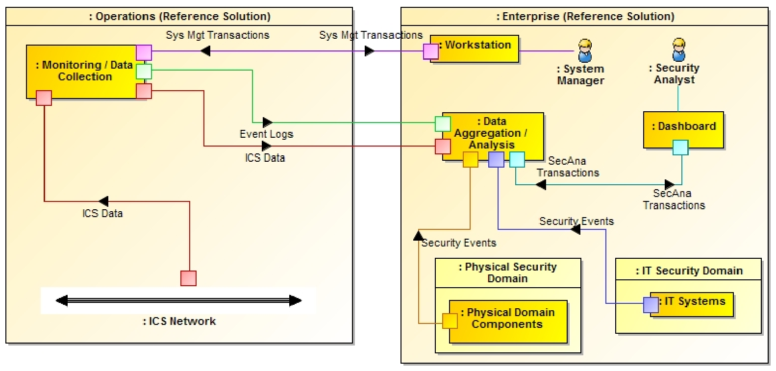
In addition to the unidirectional flow of monitoring data out of operations, an on-demand, limited-access bidirectional system management connection is provided from the enterprise to each operations facility. This connection provides remote access to manage the software that monitors the ICS network and operations components.
Figure 4-2 provides a color-coded legend identifying the different types of network connections portrayed in diagrams throughout Section 5.
Figure 4-2 Network Connections Color Code
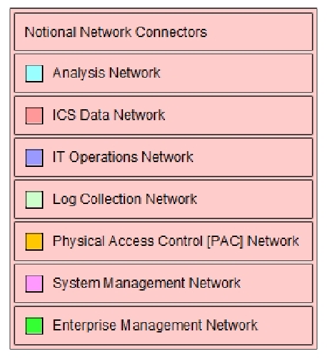
- Analysis network – connects situational awareness analysis functions
- ICS Data Network – connects ICS monitoring functions
- IT Operations Network – connects IT business systems
- Log Collection Network – connects log collection and aggregation functions
- PAC Network – connects physical access control functions
- System Management Network – provides system managers with remote access to ICS monitoring functions
- Enterprise Management Network – provides vendor with remote access to the NCCoE energy sector lab
4.2. Example Solution Monitoring, Data Collection, and Analysis
Figure 4-3 depicts the monitoring and data collection components deployed in operations and the data aggregation and analysis components deployed as enterprise services. Operations has five main sources of monitoring information:
- ICS Asset Management System – monitors the ICS network to identify the devices connected to and communicating over the network. It sends an event to the enterprise SIEM system when a new device is identified on the ICS network or if a known device disappears from the network.
- ICS Network IDS – monitors ICS network traffic for traffic that matches a signature of known suspicious activity. When suspicious activity is detected, an event is sent to the enterprise SIEM.
- Historian – collects parameter values from the ICSs in operations and replicates them to a second historian in enterprise. The operations historian is assumed to be an existing ICS component.
- Log Collector/Aggregator – collects log data from all of the other monitoring components in operations, stores them locally, and replicates the log data to another log collector aggregator in enterprise. Logs are captured and stored locally to prevent loss of log data should communication between operations and enterprise be disrupted.
- Physical Access Monitoring Sensors – monitor physical access to the operations facility. They detect events such as doors opening or closing and report those events to the PACS in enterprise.
A unidirectional gateway connects monitoring functions in operations to analysis functions in enterprise. This ensures that data flows in only one direction: out of operations.
Enterprise contains the following components:
- Log Collector/Aggregator – receives log data from the operations facilities and sends it to the SIEM.
- PACS – monitors physical access to all facilities and generates events to the SIEM when physical access occurs, such as doors or windows being opened and closed.
Figure 4-3 Monitoring, Data Collection, and Analysis Example Solution
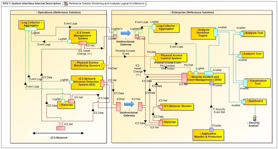
- Historian –receives replicated ICS data from the operations historian.
- ICS Behavior Monitor –compares ICS data from the historian with expected values based on normal operations. It sends events to the SIEM when ICS data deviates from normal behavior on a particular ICS network.
- Application Monitor and Protection –monitors IT applications for suspicious behavior and sends events to the SIEM.
- SIEM system –receives and stores events from sensors, normalizes the data, correlates events from multiple sensors, and generates alerts.
- Analysis Workflow Engine – to the extent feasible, automates execution of courses of action related to events collected in the SIEM.
- Analysis Tools –implement algorithms that examine data from the SIEM to identify events of interest and potential cyber incidents. These components report this information to security analysts via the visualization tool.
- Visualization Tool –provides alerts and other cyber SA information to security analysts and allows them to examine the underlying data that leads to an alert.
Enterprise components serve one of two primary responsibilities: collect event data from operations into a common repository, the SIEM; or analyze data in the SIEM to detect suspicious events and potential cyber incidents.
A data diode is used to ensure that the data flows from the components in operations that monitor the ICS network are one-way data flows from operations to enterprise.
4.2.1. Example Solution Monitoring and Data Collection Lab Build
Figure 4-4 shows the products used to build an instance of the monitoring and data collection portion of the example solution. The instance was constructed at the University of Maryland’s (UMD’s) power cogeneration plant. As a result of this collaboration with UMD, the NCCoE was able to utilize real grid data and process it through our build collaborator’s security devices and applications. Though this certainly added to the complexity of the build, we believe that using UMD’s grid data provides a real-life implementation of ICS network security solutions that can be replicated at other utilities.
The NCCoE energy sector lab provides the enterprise facility described in the example solution. A virtual private network (VPN) is used in the lab build to protect data in transit between the operations facility and the enterprise facility. The VPN was established by using a Siemens RUGGEDCOM RX1501 (O1) at the cogeneration facility and a Siemens RUGGEDCOM RX1400 at the NCCoE. The RX1501 includes firewall capabilities to control which TCP ports are available to communicate with the NCCoE.
When implementing the example solution, utilities need to consider the type of network connection in place between operations and enterprise to determine what protection might be needed for data in transit.
The physical access sensor in the example solution is provided by an RS2 door controller (O4). The controller monitors a door open/close switch and sends events whenever the door at the facility is opened or closed. This information is sent over the build collaborator’s enterprise network. To prevent unintended interactions between the collaborator’s enterprise network and the NCCoE energy sector lab, a Schneider Electric Tofino Firewall (O3) is installed between the collaborator’s enterprise network and the VPN.
A Dell R620 server (O6) running VMware (O7) was deployed to the cogeneration facility to host monitoring and data collection software. These are infrastructure components needed for the lab build but not considered critical to the example solution, as server types and VMware versions will vary depending on the implementation.
The historian in the example solution was implemented by an OSIsoft Pi Historian (O8) installed on the Dell server (O6). In this case, the historian was not an existing component in the facility. This facility uses a Schneider Electric Citect SCADA system to control operations. ICS data for the facility is collected and stored by this Citect SCADA system. To collect this data, the OSIsoft Citect Interface software (O13) is used to pull data from the Citect SCADA system (U1) and store it in an OSIsoft Pi Historian (O8). To ensure that data flow from the Citect SCADA system (U1) to the OSIsoft Pi Historian (O8) is unidirectional, the Citect Interface software (O13) is installed on a dedicated physical server (O12), isolated from the Citect SCADA system by a Schneider Electric Tofino Firewall (O20), and isolated from the Pi Historian (O8) by a Radiflow 3180 firewall (O14). The Pi Historian (O8) replicates data to another Pi Historian in the NCCoE energy sector lab.
Figure 4-4 Operations Monitoring and Data Collection Lab Build Architecture
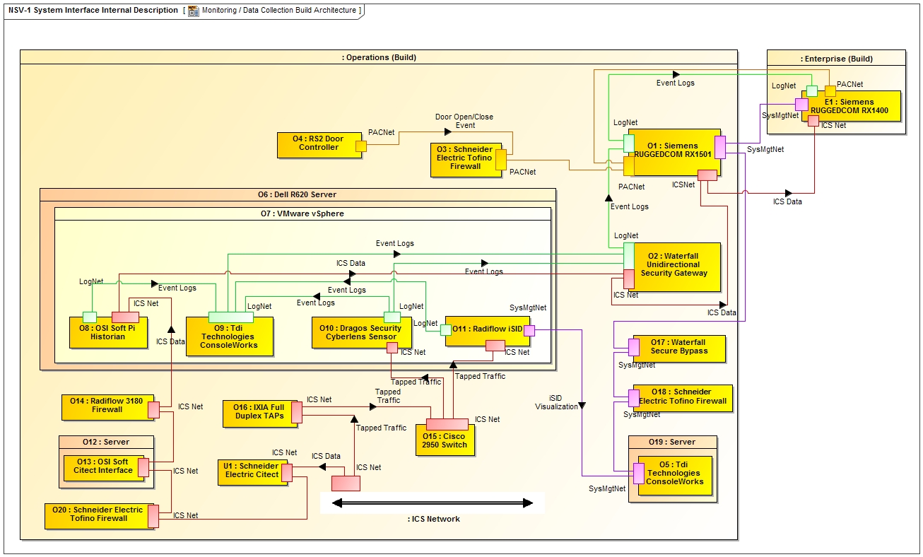
The ICS Asset Management System in the example solution is implemented by Dragos Security CyberLens. CyberLens is deployed in the cogeneration facility as a sensor (O10), which monitors the ICS network, collects relevant information in files, and transfers the files to a CyberLens server in the NCCoE energy sector lab.
The ICS IDS component in the example solution is provided by Radiflow iSID (O11). Events detected by iSID (O11) are sent via syslog to the log collector/aggregator implemented by TDi Technologies ConsoleWorks (O9). In addition to log data from iSID (O11), ConsoleWorks (O9) also collects log data via syslog from CyberLens Sensor (O10) and the Pi Historian (O8). ConsoleWorks (O9) augments the syslog records with an additional time stamp and an integrity seal. These records are stored in files that are transferred to another instance of ConsoleWorks in the NCCoE energy sector lab.
Both CyberLens Sensor (O10) and iSID (O11) need ICS network data as input. To get this data without affecting the network traffic used to run the cogeneration facility, IXIA full duplex taps (O16) were installed in the ICS network at appropriate points. These taps are designed to ensure that ICS network traffic flow continues even if power to the tap is interrupted. The taps are connected to a Cisco 2950 network switch (O15). The span port of the switch is connected to both CyberLens Sensor (O10) and iSID (O11) to provide the necessary network data. Both the taps (O16) and the span port on the switch (O15) are inherently unidirectional so that ICS network data can flow only out of the ICS network to the data aggregation and analysis tools in the NCCoE energy sector lab. No data can flow back into the ICS network from the monitoring and data collection components.
Data transferred from the Pi Historian (O8), CyberLens Sensor (O10), and ConsoleWorks (O9) to the NCCoE energy sector lab is sent by using a Waterfall Security Solutions, Ltd. Unidirectional Security Gateway (O2). This gateway ensures that data can physically flow only out of the cogeneration facility to the NCCoE and is not physically able to flow back from the NCCoE to the facility.
Radiflow’s iSID (O11) has a web interface that is used to both manage the system and provide security analysts with access to additional information about events reported via syslog. Access to this web interface is provided via components (O17, O18, O19, and O5) originally intended for remote management of monitoring and data collection components. These components are described in Section 4.3.1.
4.2.2. Example Solution Data Aggregation and Analysis Lab Build
Figure 4-5 shows the products used to build an instance of the data aggregation and analysis portion of the example solution. The instance was constructed in the NCCoE energy sector lab. This lab provides the enterprise environment in the example solution. The VPN between the operations and enterprise in the example solution is provided by a Siemens RUGGEDCOM RX1400 (E1) in the lab and an RX1501 (O1) in the cogeneration facility.
A Dell server cluster (E2) running VMware (E3) is installed in the NCCoE energy sector lab to host monitoring and data aggregation and analysis software. A separate server in the lab (E11) hosts HPE ArcSight. These are infrastructure components needed for the lab build but not considered part of the example solution.
The SIEM in the example solution is provided by HPE ArcSight (E12). ArcSight is the central repository for all events generated.
Waratek Runtime Protection (E10) implements the application monitor and protection component of the example solution. Waratek Runtime Protection monitors and protects Java applications to detect potential cross-site scripting attacks. A Java application was written to access data from the enterprise OSIsoft Pi Historian (E4) database. This application is monitored by Waratek Runtime Protection (E10) and reports and blocks attempted SQL injection attacks against the historian (E4) to ArcSight (E12).
Figure 4-5 Enterprise Data Aggregation and Analysis Lab Build Architecture
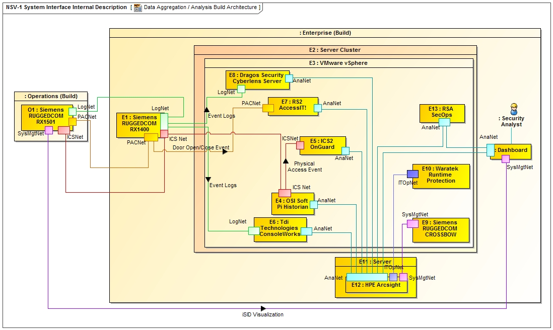
The ICS Asset Management System in the operations facilities of the example solution is provided by Dragos Security CyberLens. As implemented, CyberLens is divided into two parts: a sensor (O10) in operations and a server (E8) in enterprise. The sensor (O10) sends data files to the server (E8) for analysis. When the server detects a change to the assets on the ICS network in operations, it sends an event to ArcSight (E12).
The PACS in the example solution is implemented by RS2 AccessIT! (E7). Door open/close events from the RS2 door controller (O4) in operations are sent to AccessIT! (E7) and stored in an internal database. An ArcSight database connector is used to extract these events and send them to ArcSight (E12).
The enterprise historian is provided by the OSIsoft PI Historian (E4). ICS data from the operations Pi Historian (O8) is replicated to the enterprise PI Historian (E4). This data is used by the ICS behavioral monitoring component in the example solution, implemented by ICS2 OnGuard (E5), to detect unusual ICS behavior. OnGuard (E5) reports this unusual behavior to ArcSight (E12).
The enterprise log collector/aggregator component in the example solution is provided by TDi Technologies ConsoleWorks (E6). This instance of ConsoleWorks (E6) receives files from the operations instance (O9). The files contain integrity-sealed syslog records. The enterprise instance of ConsoleWorks (E6) verifies the integrity seal on the records and sends the syslog records to ArcSight (E12).
Siemens RUGGEDCOM CROSSBOW (E9), which implements part of the remote management connection described in Section 5.3, sends log information about remote management actions to ArcSight (E12).
The analysis workflow engine, analysis tools, and visualization tools in the example solution are implemented by RSA SecOps (E13). This product extracts event data from ArcSight (E12) and performs analyses to identify potential cyber incidents.
4.3. Example Solution Remote Management Connection
Because elements of the example solution are separated from the system managers who install, configure, and manage them, a remote management connection is needed from the enterprise to operations. Additionally, while not part of the example solution, the vendors who collaborated with the NCCoE to construct the lab build of the example solution need remote access to the NCCoE energy sector lab to install, configure, and integrate their products. Figure 4-6 depicts the example solution for both remote management connections. Example implementation of remote management is depicted in Figure 4-7 and Figure 4-8.
Figure 4-6 Remote Management Example Solution
A workstation in the enterprise facility connects to the operations EACMS. The system manager authenticates to the EACMS and controls the system manager’s access to hardware or software within operations, as a privileged user, to perform system management functions. A VPN is used to protect data in transit between operations and enterprise. In the lab build, the connection between operations and enterprise uses the public internet. Hence, protection for data transiting the internet is needed. When implementing the example solution, utilities need to consider the type of network connection in place between operations and enterprise to determine what protection might be needed for data in transit.
To install and manage their software in enterprise, vendors connect via VPN to an EACMS in enterprise. The vendors authenticate to the EACMS and are granted access to the software they provided.
4.3.1. Example Solution Operations Remote Management Lab Build
The lab build of operations remote management, depicted in Figure 4-7, provides two distinct implementations of the EACMS. One implementation, which provides remote management for software running on the Dell R620 server (O6), uses the Siemens RUGGEDCOM RX1501 (O1), the Waterfall Secure Bypass switch (O17), a Schneider Electric Tofino Firewall (O18), a Linux server (O19), and an instance of TDi Technologies ConsoleWorks (O5). The second implementation, which provides remote management for hardware in operations, uses Siemens RUGGEDCOM CROSSBOW (E9) and the Station Access Controller capability in the Siemens RUGGEDCOM RX1501 (O1). While the build used each implementation for a specific set of resources, either hardware or software, each implementation can manage both hardware and software.
Figure 4-7 Operations Remote Management Lab Build Architecture
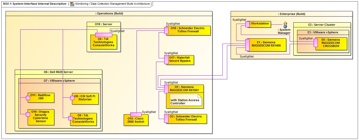
The EACMS implementation for remote management of software in operations has the system manager connect to operations from enterprise over the VPN created by using the Siemens RUGGEDCOM RX1400 (E1) and RX1501 (O1). The system manager needs to connect to the operations management instance of ConsoleWorks (O5) for role-based access control, logging, auditing, and alerts. However, a Waterfall Secure Bypass (O17) is installed in the network path from the RX1501 to the ConsoleWorks (O5). The Secure Bypass (O17) is a normally open physical switch. To manage remotely, a person in the operations facility must turn a key on the Secure Bypass (O17) to close the switch. In this lab build, the collaborator’s cogeneration facility representing operations is a staffed facility, so an operator is available to close the switch on the Secure Bypass (O17). Once the switch is closed, a timer is activated that automatically opens the switch after a preset time period. Remote management can be performed only if the personnel at the operations facility agree to allow access.
A Schneider Electric Tofino Firewall (O18) restricts the protocols that can be used to connect to the operations management instance of ConsoleWorks (O5). Once connected to O5, the system manager authenticates to ConsoleWorks, which controls privileged user access to virtual machines on the Dell server (O6). ConsoleWorks records all privileged user actions.
To remotely manage hardware in operations, the system manager authenticates to Siemens RUGGEDCOM CROSSBOW (E9) in enterprise. CROSSBOW (E9) determines the resources that the system manager is allowed to access and then makes a connection over the VPN to the resource in the RX1501 (O1). In the lab build, the Tofino Firewall (O3) isolating the door controller is connected directly to the network switch in the RX1501 (O1), and no operations personnel action is needed to manage the firewall. To manage the Cisco 2950 network switch that connects ICS network taps (O15) to CyberLens Sensor (O10) and iSID (O11), operations personnel must close the switch on the Secure Bypass (O17).
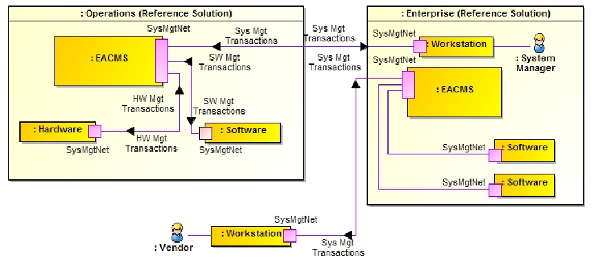
4.3.2. Example Solution Enterprise Remote Management Lab Build
Figure 4-8 depicts implementation of remote access to the NCCoE energy sector lab for vendors.
Figure 4-8 Enterprise Remote Management Lab Build Architecture
The VPN providing vendor connectivity to the enterprise in the example solution is provided as core lab infrastructure by the NCCoE and is outside the scope of the lab build. Use of this VPN requires two-factor authentication.
The EACMS for vendor access in the example solution is implemented by TDi Technologies ConsoleWorks (E6). Vendors authenticate to ConsoleWorks and are allowed to connect to the virtual machines or physical server hosting their product(s). Additionally, ConsoleWorks records all the actions performed over a connection. This provides an audit trail that documents vendor activity, which can be used for accountability as well as constructing the how-to portion, volume C, of this practice guide.
5. Security Characteristic Analysis
We organized the security evaluation of the SA reference design into two parts. Section 5.1, Analysis of the Reference Design’s Support for Cybersecurity Framework Subcategories, analyzes the SA reference design in terms of the specific Subcategories of the Cybersecurity Framework [4] that it supports. It identifies the security benefits provided by each of the reference design components and how the reference design supports specific cybersecurity activities, as specified in terms of Cybersecurity Framework Subcategories.
Section 5.2, Analysis of Reference Design Security, discusses potential new vulnerabilities and attack vectors that the reference design, or the infrastructure needed to manage the reference design, might introduce, as well as ways to mitigate those vulnerabilities. Overall, the purpose of the security characteristics analysis is to identify the security benefits provided by the reference design and how they map to Cybersecurity Framework Subcategories, as well as to understand the mitigating steps to secure the reference design against potential new vulnerabilities.
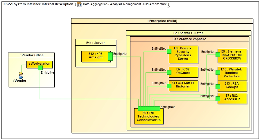
5.1. Analysis of the Reference Design’s Support for Cybersecurity Framework Subcategories
Table 5-1, SA Reference Design Components and the Cybersecurity Framework Subcategories that They Support, lists numerous reference design components, their functions, and the Cybersecurity Framework Subcategories that they support. Although the particular products that were used to instantiate each component in the build are also listed, the focus of the security evaluation is the Cybersecurity Framework Subcategories supported by these products. This evaluation does not concern itself with specific products or their capabilities. In theory, any number of commercially available products could be substituted to provide the security capabilities of a given reference design component. Figure 5-1 and Figure 5-2 depict the monitoring/data collection and data aggregation/analysis subarchitectures of the reference design by using the generic names of each component.
Figure 5-1 Monitoring/Data Collection Subarchitecture Depicted with Generic Component Names
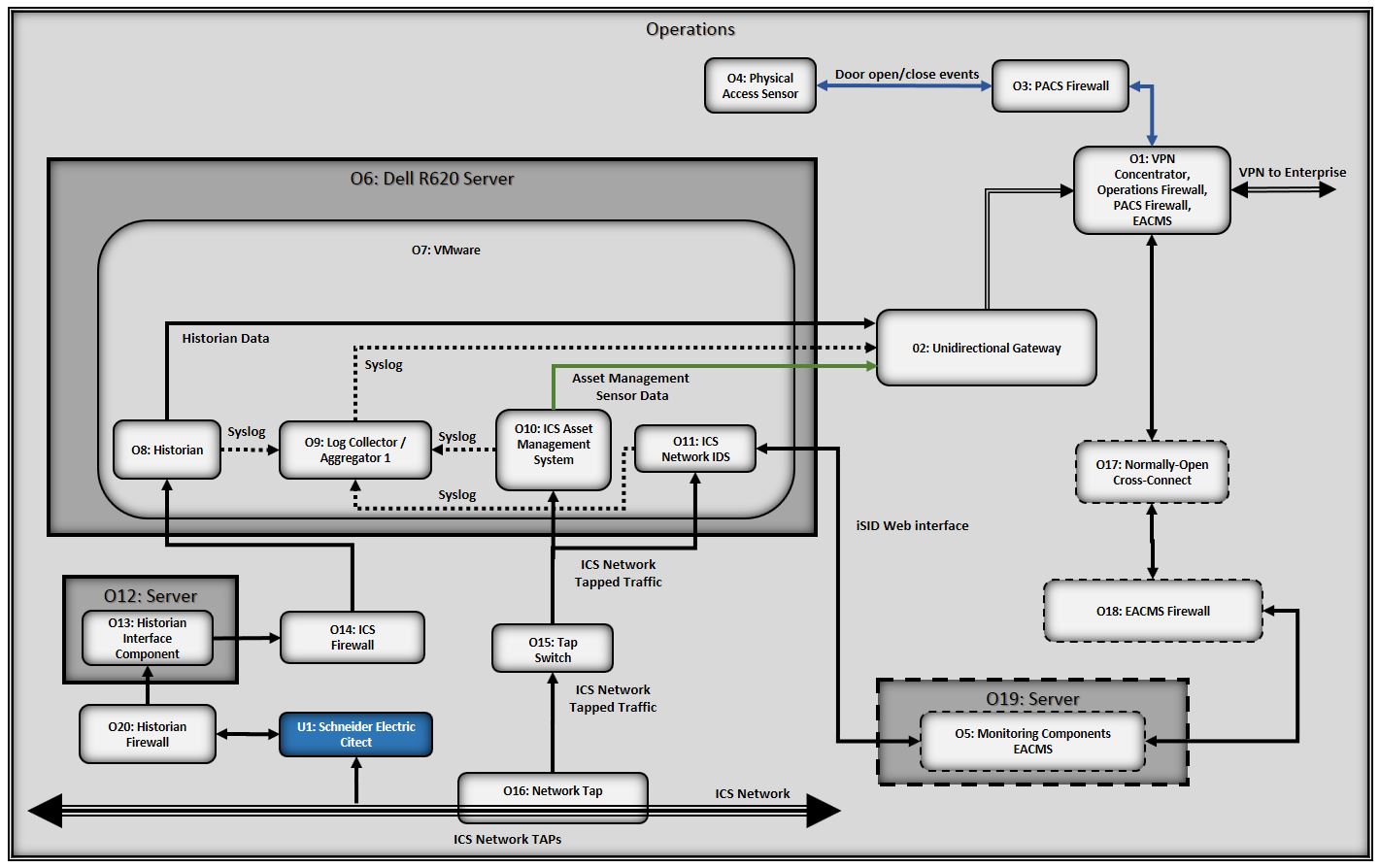
Figure 5-2 Data Aggregation/Analysis Subarchitecture Using Generic Component Names
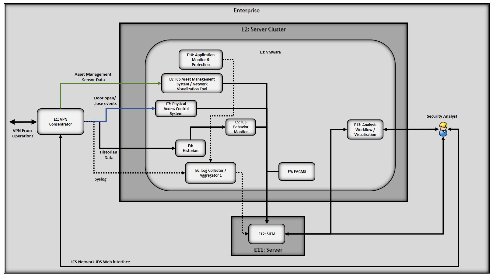
Table 5-1 SA Reference Design Components and the Cybersecurity Framework Subcategories that They Support
| Component | ID | Specific Product | Function | Cybersecurity Framework Subcategories |
|---|---|---|---|---|
| SIEM | E12 | HPE ArcSight Please note: HPE in this project is now Micro Focus Government Solutions, which acquired the suite of products and solutions used by the NCCoE in this build. | Aggregates all IT, Windows, OT (ICS), and physical access monitoring, event, and log data collected by the reference design. Acts as a data normalization and correlation point and enables queries to be developed and executed to detect potential security incidents. Serves as the central location at which the analyst can access all data collected. | DE.AE-3, DE.AE-5 Related Subcategories: PR.PT-1, DE.CM‐1, DE.CM‐2, DE.CM‐3, DE.CM‐7 |
| Network Tap | O16 | IXIA Full Duplex Tap | Collect data from specific locations on the ICS network and send it to the monitoring server via the ICS firewall. The taps are passive, so if they lose power or otherwise fail, they will not adversely affect the ICS network. Also, they collect data via monitor ports that are inherently unidirectional (and so do not pose any threat of information leaking from the tap onto the ICS network). | DE.CM‐1 |
| Log Collector/ Aggregator | O9 E6 |
TDi Technologies ConsoleWorks (Operations) | Log collection and aggregation; adds a time stamp and integrity seals the log entries. Log collection in the operations facility protects against potential data loss if the communication channel between the operations and enterprise facilities fails. Aggregating the log entries of all monitoring components at the operations log collector/aggregator ensures that this log data gets buffered in the operations facility and can be transferred later if connectivity to the enterprise network is lost. Note that two instances of the log collector/aggregator component are present in the reference design: one in the reference design’s monitoring/data collection subarchitecture and another in its data aggregation/analysis subarchitecture. Integrity seals that are applied by a log collector/aggregator can be verified only at that log collector/aggregator. Therefore, the log collector/aggregator that is in the operations facility does not apply an integrity seal to its entries because these integrity seals cannot be verified in the enterprise. | PR.DS-6, PR.PT-1, DE.AE-3 |
| ICS Asset Management System | O10 | Dragos Security CyberLens Sensor |
|
ID.AM-1 |
| Network Visualization Tool | E8 | Dragos Security CyberLens Server |
|
Does not directly support a Cybersecurity Subcategory. Related Subcategory: ID.AM-3 |
| PACS | E7 | RS2 AccessIT! |
|
PR.AC-2 |
| Physical Access Sensor | O4 | RS2 Door Controller |
|
DE.CM-2 |
| ICS Network IDS | O11 | Radiflow iSID |
|
DE.AE-1, DE.AE-5, DE.CM-1, DE.CM-7 |
| Historian | O8 | OSIsoft Pi Historian |
|
Does not directly support a Cybersecurity Framework Subcategory. Provides data to be monitored by the ICS behavior monitor. Related Subcategories: DE.AE-5, DE.CM-1 |
| ICS Behavior Monitor | E5 | ICS2 OnGuard |
|
DE.AE-5, DE.CM-1 |
| Application Monitor and Protection | E10 | Waratek Runtime Protection |
|
DE.AE-2, DE.AE-4, DE.AE-5, DE.CM-4 |
| Analysis Workflow Engine | E13 | RSA NetWitness SecOps Manager |
|
DE.AE-2 |
| Unidirectional Gateway | O2 | Waterfall Unidirectional Security Gateway |
|
PR.AC-5, PR.PT-4 |
| Visualization Tool | E13 | RSA SecOps |
|
Does not directly support a Cybersecurity Framework Subcategory. Related Subcategory: ID.AM-3 |
| EACMS | O5 | TDi Technologies ConsoleWorks |
|
PR.AC-3, PR.AC-4, PR.PT-1, PR.PT-3, PR.MA-2, DE.CM-3 |
| E9 | Siemens RUGGEDCOM CROSSBOW |
|
PR.AC-3, PR.AC-4, PR.PT-1, PR.PT-3, PR.MA-2, DE.CM-3 | |
| O17 | Waterfall Secure Bypass |
|
PR.AC-5, PR.PT-4 | |
| O18 | Schneider Electric Tofino Firewall |
|
PR.AC-5, PR.PT-4 |
The last column of Table 5-1 lists the Cybersecurity Framework Subcategories that each component of the reference design supports. In Section 3.4.2, Security Control Map, the Cybersecurity Framework Subcategories are mapped to specific sections of informative references that are composed of existing standards, guidelines, and best practices for that Cybersecurity Framework Subcategory. In conjunction with these references, the Cybersecurity Framework Subcategories can provide structure to the assessment of the security support provided by the SA reference design. The references provide use case validation points in that they list specific security traits that a solution that supports the desired Cybersecurity Framework Subcategories would be expected to exhibit. Using the Cybersecurity Framework Subcategories as a basis for organizing our analysis allowed us to systematically consider how well the reference design supports specific security activities and provides additional confidence that the reference design addresses the SA use case security objectives. The remainder of this subsection discusses how the reference design supports each of the identified Cybersecurity Framework Subcategories.
5.1.1. Cybersecurity Framework Subcategories that Are Supported
The reference design’s primary focus is the Detect function area of the Cybersecurity Framework as well as a few Subcategories within the Identify and Protect function areas. Specifically, the reference design supports:
- all five Subcategories of the Anomalies and Events Category of the Detect function area (DE.AE)
- five of the eight Subcategories of the Security Continuous Monitoring Category of the Detect function area (DE.CM)
- one activity in the Identify function area, which is in the Asset Management Category (ID.AM)
- nine activities from various Categories of the Protect function area (PR.AC-2, 3, 4, 5; PR.DS-2; PR.DS-6; PR.IP-1, and PR.PT-1, 3, 4)
We discuss these Cybersecurity Framework Subcategories in the following subsections.
5.1.1.1. DE.AE-1: A baseline of network operations and expected data flows for users and systems is established and managed
This Cybersecurity Framework Subcategory is supported by the ICS network IDS component of the reference design. This component is a tool for identifying, monitoring, and reporting anomalous ICS traffic that might indicate a potential intrusion. This component, located in the monitoring server, sends syslog events regarding anomalous behavior that it detects to the log collector/aggregator in the monitoring server, which forwards them to the SIEM on the enterprise network, where they can be viewed by a security analyst. In addition to having the ability to send syslog events, the ICS network IDS component also has its own graphical user interface that can be accessed only by a web interface.
5.1.1.2. DE.AE-2: Detected events are analyzed to understand attack targets and methods
This Cybersecurity Framework Subcategory is supported by both the application monitor and the analysis workflow engine components, both of which are located in the data aggregation/analysis subarchitecture. The application monitor monitors a running application, analyzes the data it collects, and detects and reports unusual application behavior. In the build, the application monitor is configured to generate an alert if it detects a potential SQL injection attack against the SIEM. The analysis workflow engine, located downstream from the SIEM, automates workflows associated with review and analysis of data that has been collected at the SIEM. It consists of various analytic engines that can be orchestrated. This component enables the automated execution of well-defined courses of action that can be associated with an observable sequence of events.
In some cases, the individual monitoring components in the reference design will be able to single-handedly detect events. In other cases, the aggregation and correlation of event data from multiple sources and sensors might be needed to identify anomalies and thereby enable such detection.
Although ensuring that security analysts study, analyze, and understand attack targets and methods is outside the scope of the reference design, the objective of the reference design is to support and facilitate the ability of the analyst to perform these functions. When possible, analysis and anomaly detection procedures might be automated within various components. For events that are not detected automatically, the aggregation of all SA information at the single, centralized SIEM enables analysts to more easily correlate and visualize multiple facets of SA, facilitating their ability to analyze and understand attack targets and methods.
5.1.1.4. DE.AE-4: Impact of events is determined
This Cybersecurity Framework Subcategory is supported by the application monitor component, which monitors a running application, analyzes the data it collects, and detects and reports unusual application behavior (e.g., a potential SQLi attack).
5.1.1.5. DE.AE-5: Incident alert thresholds are established
Although determining incident alert threshold values is outside the scope of the reference design, various reference design components support the ability to establish such thresholds and act upon them when they are exceeded. Cybersecurity Framework Subcategory DE.AE-5 is supported by four components in the reference design: SIEM, ICS network IDS, ICS behavior monitor, and application monitor, each of which generates alerts to report some form of unusual behavior once the detected behavior exceeds established thresholds. The incident alert thresholds in the SIEM might refer to anomalies that are detected as a result of IT, OT, and PACS information correlation. The thresholds in the ICS network IDS might refer to levels of anomalous ICS traffic. ICS behavior monitor component thresholds might refer to ICS process variable anomaly levels. application monitor component thresholds are designed to detect and alert to unusual IT application behavior.
Although the historian component of the reference design does not support this Cybersecurity Framework Subcategory directly, it provides data to the ICS behavior monitor and thereby supports this Subcategory indirectly. The ICS network contains a component that acts as a historian, recording important information regarding events and variable values for various ICS components. All process values stored in this ICS historian are conveyed to the historian component of the reference design via a historian interface component. As a result, the reference design’s historian component essentially replicates the ICS historian’s database of values that have been collected and monitored.
The historian component’s database is not a typical SQL database. It has the capability to issue an “on change” request, meaning that it can be configured to send notices when changes to certain ICS process values occur. This capability enables the reference design to avoid constant polling of historian component values and constitutes a first line of monitoring defense against potential cybersecurity events on the ICS network that might be detected when the alert thresholds are exceeded for specific ICS variable values.
5.1.1.6. DE.CM-1: The network is monitored to detect potential cybersecurity events
This Cybersecurity Framework Subcategory is supported by three components:
- Network Tap: collects data from specific locations on the ICS network and sends it to the monitoring server
- ICS Network IDS: monitors ICS traffic and reports anomalous ICS traffic that might indicate a potential intrusion
- ICS Behavior Monitor: monitors ICS process variable values in the historian to assess application behavior, detect process anomalies, and generate alerts
Although the historian component does not support this Subcategory directly, it can be configured to generate alerts when ICS process variable values change. This Subcategory is also listed as being related to the SIEM due to the SIEM’s role as the aggregation point for all collected information, which enables it to support network monitoring to detect potential cybersecurity events.
5.1.1.7. DE.CM-2: The physical environment is monitored to detect potential cybersecurity events
This Cybersecurity Framework Subcategory is supported by the physical access sensor component, which senses door close/open events and generates alerts when door open and close events occur. The physical access sensor component serves as a sort of placeholder for multiple potential PACS monitoring devices that could and should be included in an operational deployment. In an operational deployment, organizations would likely include additional PACS monitoring devices, such as badge readers, to increase the amount and quality of PACS information provided as part of SA. In a real deployment, information coming out of the PACS would include not only door open/close events but also access decisions based on the identity and permissions of the individuals trying to access the doors. All such monitored PACS (and IT and OT) information is aggregated in the SIEM, which is why Cybersecurity Framework Subcategory DE.CM-2 is listed as related to the SIEM. As the aggregation point for all collected PACS data, the SIEM can therefore support monitoring of the physical environment to detect potential cybersecurity events.
5.1.1.8. DE.CM-3: Personnel activity is monitored to detect potential cybersecurity events
This Cybersecurity Framework Subcategory is supported by the EACMS for system managers. All system manager actions are captured by the EACMS and can be provided to the SIEM for review and correlation with other system activity.
5.1.1.9. DE.CM-4: Malicious code is detected
This Cybersecurity Framework Subcategory is supported by the application monitor and protection component, which monitors a running application, analyzes the data it collects, and detects and reports unusual application behavior (e.g., a potential SQL injection attack). Because the reference design focuses mostly on collecting and integrating OT information and assumes that collection and integration of IT information into the SIEM is a solved problem, the application monitor component serves as a sort of placeholder for multiple potential IT monitoring devices that could and should be included in an operational deployment. In an operational deployment, organizations would likely include additional IT monitoring capabilities such as anti-virus software to increase the amount and quality of IT information provided as part of SA.
5.1.1.10. DE.CM-7: Monitoring for unauthorized personnel, connections, devices, and software is performed
This Cybersecurity Framework Subcategory is supported by the ICS network IDS component, which identifies, monitors, and reports anomalous ICS traffic that might indicate a potential intrusion on the OT network. This Subcategory is also listed as related to the SIEM. The SIEM serves as the aggregation point for all collected information and can therefore support monitoring for unauthorized personnel, connections, devices, and software.
5.1.1.11. ID.AM-1: Physical devices and systems within the organization are inventoried
This Cybersecurity Framework Subcategory is supported by the ICS asset management system component, which monitors ICS traffic to sense, track, and record ICS assets, and maintains a database of all ICS assets of which it becomes aware. Such monitoring enables this component to detect and identify new devices on the ICS network, devices that disappear from the ICS network, and changes to known ICS devices. This enables it to perform data analytics and anomaly detection as well as management of the inventory of ICS assets that it senses and collects. The ICS asset management system sends logs of asset inventory events to the log collector/aggregator and feeds the ICS asset information it collects into the SIEM component.
5.1.1.12. PR.AC-2: Physical access to assets is managed and protected
This Cybersecurity Framework Subcategory is supported by the reference design’s PACS, which controls user access to doors and detects and reports door open/close events. As was stated earlier, the reference design’s physical access sensor and control system components serve as placeholders for multiple potential PACS monitoring devices that could and should be included in a reference design deployment to manage and protect physical access to assets. For example, organizations would likely want to include badge readers to support access decisions based on the identity and permissions of the individuals trying to access the doors. The reference design provides the vehicle for integrating information from additional PACS devices into the SIEM.
5.1.1.13. PR.AC-3: Remote access is managed
This Cybersecurity Framework Subcategory is supported by the functions that compose the EACMS. Together, these functions allow carefully controlled and monitored remote access to manage monitoring systems deployed to operations.
5.1.1.14. PR.AC-4: Access permissions are managed, incorporating the principles of least privilege and separation of duties
This Cybersecurity Framework Subcategory is supported by the functions that compose the EACMS. These functions allow definition and enforcement of role-based access permissions that incorporate least privilege and separation of duties.
5.1.1.15. PR.AC-5: Network integrity is protected, incorporating network segmentation where appropriate
This Cybersecurity Framework Subcategory is supported by using firewalls, a unidirectional gateway, and a normally open cross-connect. All of these functions segment the network to preserve integrity.
5.1.1.16. PR.DS-2: Data in transit is protected
This Cybersecurity Framework Subcategory is supported by use of a VPN, which uses encryption to protect the confidentiality and integrity of all information while it is in transit between the monitoring/data collection subarchitecture and the data aggregation/analysis subarchitecture. The reference design does not, however, protect the confidentiality or integrity of monitored data while it is in transit within either the monitoring/data collection subarchitecture or the aggregation/analysis subarchitecture.
5.1.1.17. PR.DS-6 Integrity-checking mechanisms are used to verify software, firmware, and information integrity
This Cybersecurity Framework Subcategory is supported by the log collector/aggregator that is in the aggregation/analysis subarchitecture of the reference design insofar as the log collector/aggregator integrity seals the log data that it collects. Ideally, the log collector/aggregator in the monitoring/data collection subarchitecture would also apply an integrity seal to each log entry so that this seal could be verified by the log collector/aggregator in the data aggregation/analysis subarchitecture to ensure that no log entries were modified before reaching the data aggregation/analysis subarchitecture log collector/aggregator. This integrity checking of monitoring/data collection log entries, however, is not currently provided in the build because there is currently no mechanism to enable any component other than the log collector/aggregator that applies the integrity seals to verify those seals. In an ideal world, all information sent from components in the monitoring/data collection subarchitecture to the aggregation/analysis subarchitecture would be integrity protected while both at rest and in transit.
5.1.1.18. PR.IP-1: A baseline configuration of information technology/industrial control systems is created and maintained
Organizations deploying this reference design should create and maintain baseline configurations so that the reference design can use these baselines to more effectively identify potential cybersecurity threats. The ICS behavior monitor component, for example, is responsible for establishing incident alert thresholds and monitoring ICS process variable values to assess application behavior and detect process anomalies that could indicate cybersecurity events. To best establish effective thresholds and detect relevant anomalies, the ICS behavior monitor and other similar components need to have some notion of typical baseline behavior for the ICS systems. The ICS behavior monitor component itself is not expected to generate such a baseline; it builds its own model of ICS behavior based on observed values in the historian. However, it does not know if that model is correct; it knows only that the model is “normal” in the sense that the model represents what it has observed. The ICS behavior monitor and other similar components would be more effective if they were provided with a baseline configuration against which to identify anomalous behavior and unexpected thresholds. Ideally, an organization deploying the reference architecture should have a mechanism for creating, maintaining, and providing such baseline behavior information to the reference design for this purpose.
5.1.1.19. PR.PT-1: Audit/log records are determined, documented, implemented, and reviewed in accordance with policy
This Cybersecurity Framework Subcategory is provided by both log collector/aggregators in the reference design, which aggregate logs from various devices and put time stamps on the log data. Although the SIEM does not directly support this Subcategory, PR.PT-1 is also listed as a related Subcategory for the SIEM because the SIEM can be used to review audit/log records.
Ideally, all of the monitoring/data collection components in the reference design will be capable of generating log data that contains the relevant event information and sending this log data to the log collector/aggregator component. (In the build, neither the PACS nor the physical access sensor sends log data that contains the events to the log collector/aggregator; instead, the SIEM obtains PACS event information via a PACS MySQL database.) The log collector/aggregator component’s role is to aggregate all log data that it collects. In addition, when each log entry is received at the log collector/aggregator, it already contains a time stamp added by the sending device. Upon receipt of the log entry, the log collector/aggregator component puts its own time stamp on the entry to indicate the time that it was received. Discrepancies in the sent and received time stamps for a given entry can be monitored to detect suspicious activity. The log collector/aggregator in the monitoring and data collection subarchitecture then sends all logs to the log collector/aggregator in the data aggregation/analysis subarchitecture, which puts its own time stamps on the entries that it receives. It also applies an integrity seal to the entry that can be checked later to ensure that the entry has not been deliberately or inadvertently modified. This log collector/aggregator then sends its log entries to the SIEM. The SIEM consolidates these log entries along with all other SA information.
The collection of SA information in a single location (at the SIEM) enables audit and log records to be reviewed easily in accordance with policy. Furthermore, the analysis tool components into which the SIEM data feeds might facilitate automation of the review of audit and log records. Whether or not the organization performs these audit and log reviews according to policy is outside the scope of the SA reference design.
5.1.1.20. PR.PT-3: Access to systems and assets is controlled, incorporating the principle of least functionality
This Cybersecurity Framework Subcategory is supported by the functions that compose the EACMS, and by network firewalls. The EACMS controls system manager access to systems in operations. Network firewalls control connectivity to and interaction among network assets.
5.1.1.21. PR.PT-4: Communication and controls networks are protected
This Cybersecurity Framework Subcategory is supported by a VPN, a firewall, a unidirectional gateway, and a normally open cross-connect. The VPN provides confidentiality protection for data in transit between the operations facilities and enterprise. Firewalls are placed throughout the system to control the network connections that are allowed among function within operations. A unidirectional gateway ensures that communication between operations and enterprise is one way out of operations. The normally open cross-connect allows a two-way communication path between operations and enterprise but only when physically closed at the operations side.
5.2. Analysis of Reference Design Security
The list of reference design components included in Table 5-1 focuses only on the components of the reference design that are needed to enable it to meet its SA objective of collecting information from the ICS network, aggregating it at a centralized location, and providing analysis capability in a manner that supports the intended Cybersecurity Framework Subcategories. Table 5-1 does not include components that are needed to manage or secure the reference design. However, the reference design itself must be managed and secured. To this end, this second part of the security evaluation focuses on the security of both the reference design itself and its management infrastructure.
Table 5-2, Components for Managing and Securing the SA Reference Design and Protecting the ICS Network, lists components that are needed to manage the reference design, secure both the reference design and the data it collects, and protect the ICS network. Table 5-2 also describes the security protections provided by each of the management and security components. As with part 1 of the security evaluation, although the products that were used to instantiate each component in the build are also listed, the security protections provided by these products are the focus of this security evaluation.
Figure 5-3 depicts the monitoring/data collection management architecture of the reference design using the generic name of each component.
Figure 5-3 Monitoring/Data Collection Management Architecture Depicted Using Generic Component Names
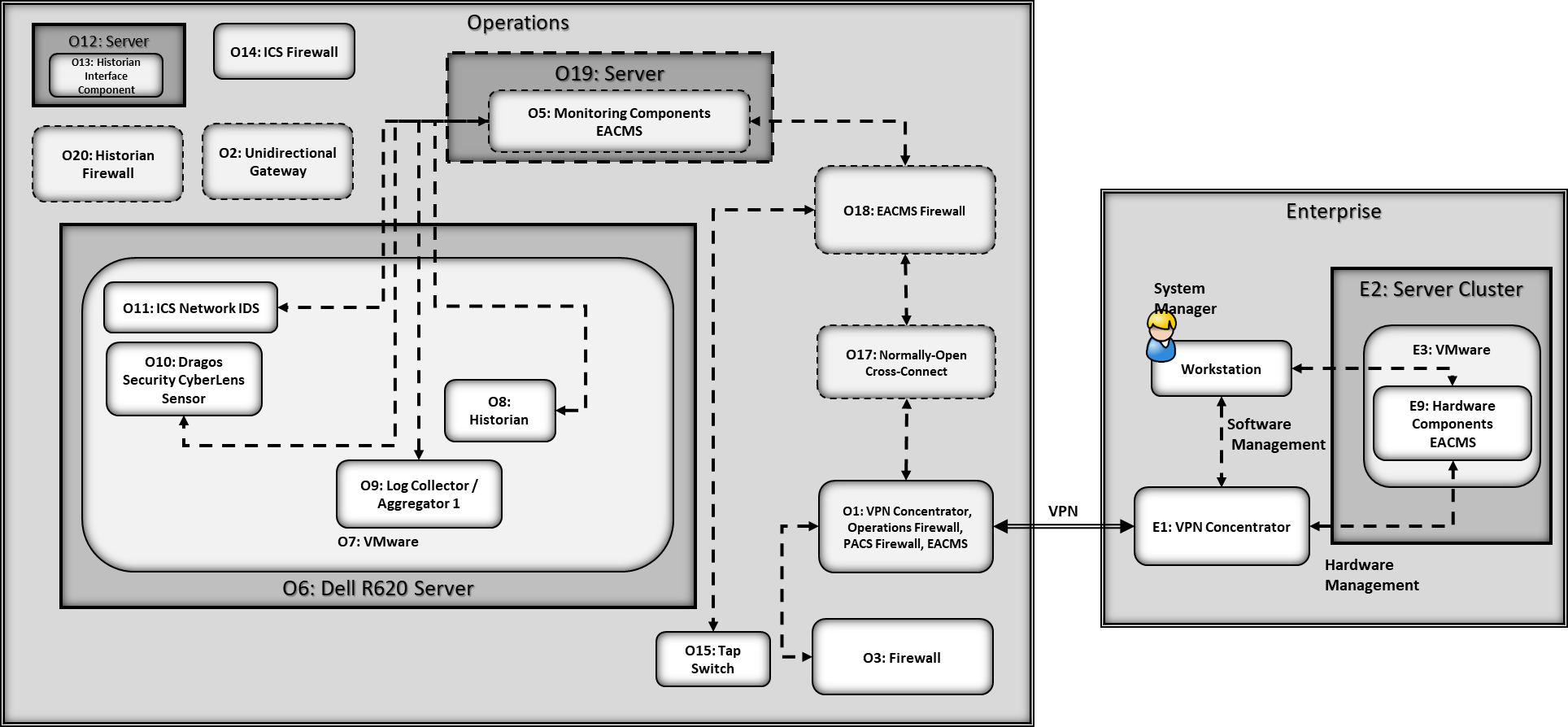
Note that because the NCCoE build used products from many different vendors, the NCCoE provided those vendors with access to the NCCoE lab for product installation, configuration, and maintenance. Therefore, the architecture that was actually instantiated included components for securing this vendor access path. However, this vendor access path is an artifact specific to the NCCoE build. It is not anticipated that organizations that adopt the SA architecture would enable such a vendor access path in their implementations. Therefore, this vendor access path is not included within the scope of the security evaluation.
Table 5-2 Components for Managing and Securing the SA Reference Design and Protecting the ICS Network
| Component | ID | Specific Product | Security Protection Provided |
|---|---|---|---|
| EACMS | O1 O5 O18 O17 |
Siemens RUGGEDCOM RX1501 TDi Technologies ConsoleWorks (Operations Management) Schneider Electric Tofino Firewall Waterfall Secure Bypass |
One EACMS component (Siemens RUGGEDCOM RX1501) enables remote configuration of privileged user access to the PACS firewall. This EACMS component is referred to as the PACS firewall EACMS. A second EACMS component (TDi Technologies ConsoleWorks) en-ables remote configuration of privileged user access to the consoles of the four components on the monitoring server (log collector/aggregator, ICS asset management system, ICS network IDS, and historian). This EACMS component is referred to as the monitoring components’ EACMS. The third EACMS component (Schneider Electric Tofino Firewall) operates as the network port and protocol level to control remote management traffic exchanged between the enterprise network and the monitoring components’ EACMS. It also serves as the EACMS for the taps switch. This EACMS component is referred to as the EACMS firewall. The fourth EACMS component (Waterfall Secure Bypass) is hardware that might be manually configured to enable data to be sent into the operations facility to support EACMS activities for a limited period of time. All EACMS components except for the Waterfall Secure Bypass, which is a physical cross-connect, also create an audit trail of all privileged user access to the components that they protect. They send log entries documenting this audit trail to the SIEM. None of the four components that compose the EACMS can be remotely managed. Each EACMS component except for the Waterfall Secure Bypass includes the three policy subcomponents listed in the next three rows of this table. |
| EACMS Policy Administration Point | O1 O5 O18 |
Siemens RUGGEDCOM RX1501 TDi Technologies ConsoleWorks (Operations Management) Schneider Electric Tofino Firewall |
The point that manages access authorization policies; it is the source of policies for the EACMS and the location at which policies might be created and edited. |
| EACMS Policy Decision Point (PDP) | O1 O5 O18 |
Siemens RUGGEDCOM RX1501 TDi Technologies ConsoleWorks (Operations Management) Schneider Electric Tofino Firewall |
the point that evaluates access requests against authorization policies for the EACMS before issuing access decisions |
| EACMS Policy Enforcement Point (PEP) | O1 O5 O18 |
Siemens RUGGEDCOM RX1501 Station Access Controller TDi Technologies ConsoleWorks (Operations Management) Schneider Electric Tofino Firewall |
The point that intercepts userʼs access request to a resource, makes a decision request to the EACMS’s PDP to obtain the access decision (i.e., access to the resource is approved or rejected), and acts on the received decision. In the build, the Siemens CROSSBOW EACMS Station Access Controller is integrated into the Siemens RUGGEDCOM RX1501 component. |
| PACS Firewall EACMS | O1 | Siemens RUGGEDCOM RX1501 | enables configuration of privileged user access to the PACS firewall to be controlled remotely in a manner similar to that in which the monitoring components’ EACMS enables configuration of privileged user access to the consoles on the monitoring server components to be controlled |
| Monitoring Components’ EACMS | O5 | TDi Technologies ConsoleWorks (Operations Management) | enables configuration of privileged user access to the consoles on the monitoring server components to be controlled remotely in a manner similar to that in which the PACS firewall EACMS enables privileged user access to the PACS firewall to be controlled |
| EACMS Firewall | O18 | Schneider Electric Tofino Firewall | Firewall that operates at the network port and protocol level to monitor all traffic received at the monitoring components’ EACMS from external sources when the normally open cross connect is closed. In addition to monitoring traffic, the firewall also restricts traffic flow according to its configured rules. This firewall’s purpose is to ensure that the only permitted components to which traffic can flow to and from the normally open cross-connect are the server for the monitoring component’s EACMS (O19) and the taps switch (O15). It is configured to permit only three types of traffic: (1) remote management traffic exchanged between the enterprise network and the monitoring components’ EACMS, which is used to control privileged user access to the consoles of the four components on the monitoring server and access to the web interface of the ICS network IDS, (2) remote management traffic exchanged between the enterprise network and the taps switch, and (3) traffic exchanged between the enterprise network and the ICS network IDS component to support the web interface that enables security analysts that are located on the enterprise network to view SA information by using the ICS network IDS component’s graphical user interface. (Note that support for this last type of traffic is one way in which the reference design differs from the build because the reference design requires that the ICS network IDS component report potential IDS events by sending syslog events; it does not require support for a graphical user interface to the ICS network IDS component. |
| PACS Firewall | O3 | Schneider Electric Tofino Firewall | Monitors traffic sent between the VPN concentrator/PACS firewall EACMS component and the physical access sensor component. Configured to ensure that the only messages that are permitted to be received from the physical access sensor are door open/close, and other valid PACS events are forwarded to the VPN concentrator. The physical access sensor sits on an operational IT network that is connected to the internet. Therefore, this PACS firewall is exposed to the operational IT network and, via that network, to the internet. So configuring the PACS firewall to accept only PACS sensor messages prevents the PACS devices and the operational network on which they sit from being used as an attack vector to compromise the reference architecture. In particular, the PACS firewall prevents traffic (other than door controller traffic) from being sent from the internet to the enterprise network via the VPN. |
| VPN Concentrator | O1 | Siemens RUGGEDCOM RX1501 | The VPN concentrator supports four types of VPN traffic between the operations facility and the enterprise network: monitoring data sent from the operations facility to the enterprise network; remote management traffic used to support privileged access to the consoles of the four components on the monitoring server; remote management traffic used to support privileged user access to the console of the PACS firewall; and web interface traffic exchanged between the ICS network IDS component and a remote security analyst located on the enterprise network. The traffic exchanged on this web interface might be either traffic needed to support remote management of the ICS network IDS component by a security analyst or traffic needed to support the ICS network IDS component’s graphical user interface. (This graphical user interface is not part of the reference design, but it is supported in the build.) |
| Operations Firewall | O1 | Siemens RUGGEDCOM RX1501 | Firewall monitoring all traffic sent between the operations facility and external sources and restricting traffic flow according to its configured rules. This firewall is the one device on the operations facility network that is exposed to the internet at all times. Regarding traffic arriving at the operations facility from external sources, it is configured to permit (1) remote management traffic exchanged between the enterprise network and the monitoring components’ EACMS, which will be further scrutinized by the EACMS firewall, (2) remote management traffic exchanged between the enterprise network and the PACS firewall EACMS, and (3) remote management traffic exchanged between the enterprise network and the taps switch. |
| Unidirectional Gateway | O2 | Waterfall Unidirectional Security Gateway Hardware | Enforces one-way transfer between a transmitter and receiver within hardware, ensuring that data may be sent from the monitoring server to the enterprise but not in the reverse direction. The gateway also replicates industrial servers and emulates industrial devices to IT users and applications. |
| Normally Open Cross-Connect | O17 | Waterfall Secure Bypass | Enables the data unidirectional gateway component to be bypassed so that data can be sent into the operations facility for specific management and monitoring purposes. Must be closed manually and stays closed only for a limited period of time. |
| ICS Firewall | O14 | Radiflow 3180 firewall | Firewall monitoring all traffic that flows from the historian interface component to the monitoring server. This firewall is configured to prevent traffic from flowing in the reverse direction, i.e., to prevent traffic from flowing from the monitoring server to the ICS network. Also, it cannot be managed remotely. |
| Historian Firewall | O20 | Schneider Electric Tofino Firewall | Firewall monitoring all traffic that flows between the ICS historian and the historian interface component. This firewall is configured to prevent traffic from flowing from the historian interface component to the ICS network. It cannot be managed remotely. |
| Historian Interface Component | O13 | OSIsoft Citect Interface | This component interfaces with the ICS historian that is on the ICS network. It receives data from the ICS historian and provides this to the historian component in the monitoring server of the SA reference architecture, but it does not permit data to travel in the other direction, from the monitoring server to the ICS historian. |
| Tap Switch | O15 | Cisco 2950 (Aggregator) | This switch aggregates data received from all ICS taps and forwards this data to the monitoring server. It is configured to permit only one-way data flow from the tap interfaces toward the monitoring server interface. No data is permitted to travel out of the tap interfaces toward the taps. |
5.2.1. Protecting the ICS Network
A main security requirement of the SA use case is to ensure that the ICS network is not impacted by the monitoring to which it is subjected. In particular, it is crucial to ensure that, although data can flow from the ICS network to the reference design, a minimal amount of very strictly restricted data is allowed to flow from the reference design onto the ICS network. There are two paths on which data flows from the ICS network to the monitoring server: from the ICS network taps, and from the ICS historian.
These taps are inherently unidirectional. By design, they permit data to flow only from the ICS network to the monitoring server. They are not able to allow data to flow from the monitoring server to the ICS network. These taps are also passive, meaning that if they were to lose power or otherwise fail, they would not disrupt the flow of data on the ICS network.
This unidirectional transmission path is enforced by the historian firewall (O20) (i.e., a Schneider Electric Tofino Firewall in the build), the historian interface component (O13), the server on which it resides, and the ICS firewall (O14) (i.e., the Radiflow 3180 firewall in the build), all of which sit between the ICS historian (i.e., Schneider Electric Citect in the build) and the monitoring server. These components are critical for ensuring that only a small amount of strictly restricted data is permitted to travel into the ICS network from the monitoring server.
In the build, the historian interface component (O13) pulls data from the ICS historian (Schneider Electric Citect, U1) and pushes this information to the historian component in the monitoring server (O8). This means that the historian interface component (O13) needs to send a message to the ICS historian (U1) that sits on the ICS to cause it to send the historian data to the historian interface component. Therefore, the historian firewall (O20) between the historian interface component and the ICS historian has to be configured to permit requests for data to flow from the historian interface component to the ICS historian. It also must be configured to allow historian data to flow in the opposite direction, i.e. from the ICS historian to the historian interface component.
The fact that requests for data pulled from the ICS historian must be permitted to be sent from the operations network to the ICS network is not ideal. To protect the ICS network, it would be preferable to prevent all data flow from the operations network to the ICS network. To ensure that requests for historian data are the only type of data that is permitted to be sent from the operations network to the ICS network, it is essential that the historian firewall (O20) that sits between these two components be configured to limit the data that is sent to the ICS network to the necessary requests for historian data and nothing more. It is also essential that this historian firewall (O20) cannot be configured remotely. This ensures that only an insider who has physical access to this firewall (O20) would be able to modify its rules to permit additional traffic to enter the ICS network from the operations network.
Once it has the historian data, the historian interface component pushes this data to the historian component (O8) on the monitoring server. This means that the firewall (O14) that sits between the historian interface component and the historian component can (and must) be configured not to permit any data to flow in the direction from the monitoring server to the historian interface component. It is also essential not to allow this firewall (O14) to be configured remotely.
In short, the reference design balances two competing goals:
- protecting the ICS network as fully as possible from receipt of potentially harmful data from the reference design itself
- enabling the ICS historian to receive requests for data from the reference design
It achieves these goals by isolating the historian interface component on both sides by firewalls, ensuring that these firewalls are configured correctly, and ensuring that neither these firewalls, the historian interface component, nor the server that the historian interface component sits on is remotely configurable. It should also be noted that the historian interface component is running on a server that is distinct from the monitoring server. This separation ensures that the reference design does not depend solely on VMware’s ability to separate applications running on it to ensure that no data is permitted to travel from the monitoring server to the historian interface component. As discussed, none of the components located between the ICS historian and the monitoring server may be managed remotely. Creating additional means to configure these components from outside the operations facility is considered a greater risk than being unable to monitor changes to these firewalls from outside the facility; therefore, only technicians physically on site at the operations facility may change the configuration of these components.
5.2.2. Protecting the Reference Design from Outside Attack
Measures implemented to protect the monitoring and data collection subarchitecture itself from outside attack include …
- The PACS firewall situated between the physical access sensors and the VPN concentrator/PACS firewall EACMS is configured to permit only door open/close events and other valid notifications to be sent from the physical access sensors to the monitoring and data collection subarchitecture. The physical access sensors sit on the facility’s operational network, which exposes them to the internet. The PACS firewall plays a crucial role in preventing external attacks to the monitoring network. It prevents the PACS devices and the operational network on which they sit from being used as an attack vector to compromise the monitoring and data collection subarchitecture.
- Data should be allowed to flow only from the enterprise network into the monitoring server under carefully controlled circumstances and with limited restrictions. The architecture’s unidirectional gateway component (i.e., the Waterfall Unidirectional Security Gateway Hardware component in the build) that sits between the monitoring server and the VPN concentrator component (i.e., the Siemens RUGGEDCOM RX1501) is designed to enforce this in a unidirectional manner. This unidirectional gateway is a combination of hardware and software. The hardware physically permits only one-way transfer across an optical connection between a hardware transmitter and a hardware receiver. The hardware ensures that monitored data may be sent from the monitoring server to the enterprise, but no data may be sent in the reverse direction on this connection into the monitoring server. Unidirectional gateway software replicates industrial servers and emulates industrial devices from the protected operations network to the enterprise network.
5.2.3. Protecting the Remote Management Paths
In the example solution presented, for the purpose of monitoring, the SA architecture design assumed that the data aggregation/analysis activity would be performed at a physically separate location from the data monitoring/collection activity. This scenario was used to reflect real-world operations; its risk is greater than the scenario in which the monitoring/data collection subarchitecture and the data aggregation/analysis subarchitecture are physically co-located in the same secure facility. Therefore, mechanisms for protecting the data and management path between the two parts of the architecture that support these activities are integral to the reference design.
For the purpose of monitoring, data should flow in a unidirectional manner from the operations facility to the enterprise network. For management purposes, however, there is a need for traffic to be able to flow into the operations facility from the enterprise network. In particular, incoming traffic is required to enable remote management of the following components:
- the PACS firewall (one of the Schneider Electric Tofino Firewalls in the build), which sits between the VPN concentrator and the physical access sensor
- the four data collection components in the monitoring server at the operations facility
- the tap switch, which sits between the ICS taps and the monitoring server
- the PACS firewall EACMS/operations firewall
Remote management traffic destined for the monitoring server or the taps switch must instead bypass the unidirectional gateway to reach its destination. This remote management traffic can be used to monitor and configure the PACS firewall.
Remote management traffic destined for the monitoring server or the taps switch must instead bypass the data diode to reach its destination. To enable this bypass, we used the normally open cross-connect component (the Waterfall Secure Bypass component in the build). Closing this normally open cross-connect enables traffic to flow back and forth between the enterprise network and the monitoring server for limited time periods.
These remote management access paths contain numerous components and features designed to secure them. These components are as follows:
VPN concentrator – is directly exposed to the internet. This component is situated on its own network in the operations facility.
Operations firewall – monitors all traffic sent between the operations facility and external sources and restricts traffic flow according to its configured rules. It is exposed to the internet at all times.
This component contains a PEP for the PACS firewall (the Schneider Electric Tofino Firewall between the RS2 Door Controller and the RUGGEDCOM RX1501 in the build). This PEP is the “station access controller” shown within the RUGGEDCOM RX1501 build diagram. It enables administrative access to the console of the PACS firewall to be managed and monitored remotely.
Normally open cross-connect – enables the unidirectional gateway to be bypassed, enabling traffic to flow into the operations facility monitoring architecture. As mentioned earlier, the unidirectional gateway sits on a path between the monitoring server and the operations firewall/VPN concentrator (RUGGEDCOM RX1500) to ensure that information can flow only in a unidirectional manner from the monitoring server to the enterprise network.
This component is a physical switch that is normally open, ensuring that no data can be transmitted across it. This switch must be closed manually with a physical key by an operator who is located on site at the operations facility to enable remote traffic to enter the monitoring/data collection portion of the architecture from the enterprise. Once closed, it will remain closed for a limited, configurable amount of time (e.g., 30 minutes), and then it will automatically open (unless explicitly opened before this time period expires). The connection cannot be enabled remotely.
EACMS firewall –is instantiated by using the Schneider Electric Tofino Firewall in the build. After passing through the VPN concentrator, the operations firewall, and the normally open cross-connect, traffic received from the enterprise flows to the EACMS firewall. Because of its placement behind the VPN concentrator, the operations firewall, and the normally open cross-connect, this component is not by default exposed to any traffic from outside the operations facility except for those periods of time when the normally open cross-connect has been explicitly closed, and traffic sent to the facility on a VPN meets the requirements for entry that are enforced by the operations firewall.
When such a connection into the operations facility from outside is established, the EACMS firewall is needed to monitor traffic being exchanged between the operations facility and the outside. This firewall operates at the network port and protocol level to monitor and control remote management traffic exchanged between the enterprise network and both the taps switch and the monitoring components’ EACMS. Three types of traffic are permitted by the EACMS firewall:
- remote management traffic exchanged between the enterprise network and the monitoring components’ EACMS (TDi Technologies ConsoleWorks), which is used to manage privileged access to each of the components on the monitoring server
- web interface traffic exchanged between the ICS network IDS component on the monitoring server and a remote security analyst located on the enterprise network. The traffic exchanged on this web interface might be needed either to support remote management of the ICS network IDS component or to enable the security analyst to view SA data via the ICS network IDS component’s graphical user interface.
- remote management traffic exchanged between the hardware component EACMS (Siemens RUGGEDCOM CROSSBOW) on the enterprise network and the taps switch, which is used to administer the taps switch
Monitoring components’ EACMS – this component is instantiated by using TDi Technologies ConsoleWorks in the build. Remote management traffic coming through the EACMS firewall to the operations facility that is destined for one of the four monitoring server components may reach those components only via the monitoring components’ EACMS. This is a component that administrators must use to configure user privileges or to access the consoles of the four components on the monitoring server. This component is connected to the consoles of each of the four applications running on the monitoring server so it can control access to these consoles and permit only those users with administrator privileges to access each console. It also records all activities that are performed on these consoles. The monitoring components’ EACMS enables the monitoring server components to be configured remotely, but the tool itself cannot be configured remotely. Web interface traffic that is sent between the ICS network IDS component (O11) and a security analyst on the enterprise network must also be sent through the monitoring components’ EACMS. This web interface traffic includes both SA monitoring data accessed via the ICS network IDS graphical user interface and traffic needed to remotely manage the ICS network IDS.
The monitoring components’ EACMS runs on a server that is separate and distinct from the monitoring server. This separation is necessary to ensure that the architecture does not depend solely on VMware’s ability to separate applications running on it, which would be the case if the monitoring components’ EACMS were on the same VMware server as the monitoring server and its components. The server on which the monitoring components’ EACMS server is running cannot be remotely managed.
PACS firewall EACMS (O1) – is instantiated in the build by using the Siemens RUGGEDCOM RX1501 component that sits on the enterprise network. It enables monitoring and configuration of user privileges on the PACS firewall (O3) in a manner similar to the monitoring components’ EACMS (O19). The PACS firewall EACMS is used to remotely configure and manage the PACS firewall, i.e., the firewall that sits between the VPN concentrator (O1) and the physical access sensors (O4).
To further protect the remote management path, the reference design does not permit any components that are in the remote management path to be remotely configurable. The only way that components and software that are in the remote management path can be administered and configured is in person.
5.2.4. Protecting the Remote Path to the IDS Web Interface
As mentioned earlier, the ICS network IDS component has a web interface that facilitates remote management and access to its graphical user interface. Because a security analyst using the web interface to view SA data is expected to be located on the enterprise network rather than at the operations center, SA traffic will flow between the ICS network IDS and the enterprise network via this web interface. Security mechanisms are needed to monitor and restrict this traffic flowing into the operations center. The web interface traffic uses the same path as traffic remotely managing the monitoring server components; it relies on the same security mechanisms as those that protect the remote management path, namely the operations firewall (O1), the normally open cross-connect (O17), the EACMS firewall (O18), and the monitoring components’ EACMS (O19).
5.2.5. Protecting the SIEM
The SIEM component enables information collected at the reference design’s disparate sensors and monitoring components to be combined, correlated, and analyzed in a way that would not be possible when using the data from a single SA component in isolation. Aggregation of SA information in the SIEM provides enormous potential in terms of anomaly detection and increased SA. Ironically, the main strength of the reference design might serve as its vulnerability unless properly protected. If a malicious actor can penetrate the SIEM to modify or delete information, alter the processes used to analyze or visualize asset information, or alter information while in transit to the SIEM, then the very system that was designed to increase SA and make a wide variety of asset information centrally available to security analysts could be used as an attack vector. It is imperative that access to the SIEM be strictly limited to a small number of authorized users. Ideally, the integrity of the monitored information will also be protected from the points at which it is collected until it reaches the SIEM component. Ensuring the integrity and completeness of all data sent to and stored in the SIEM is essential to securing the reference design solution. If the components used to implement the reference design do not inherently provide data integrity for monitored information that is sent to the SIEM, then security will rely on enforcement of strict physical access control to ensure that attackers are not given the opportunity to access and modify/delete data that is in the SIEM or in transit to the SIEM.
It is worth noting that the absence of an SIEM does not mean that an energy organization does not have this SA information stored on its networks. Access to the SA information resides instead at disparate locations on the network. Energy services organizations still need to safeguard this SA information in the various locations where it is generated and stored, and while in transit.
5.2.5.1. Controlling access to the SIEM
Only highly privileged users should be permitted to log into the SIEM. No users should be permitted to modify SA data that is being stored on this component. Monitoring, logging, and auditing of all console activity performed on this component is essential to ensuring that authorized users are not performing unauthorized activities on this component. Periodic reports should be generated, listing all users who logged into the SIEM component and activities performed.
5.2.5.2. SIEM data verification
Mechanisms are needed to help ensure that information collected or generated at a collection component is sent to and received by the SIEM, i.e., that the SIEM receives all of the monitored information that it should. If a malicious actor were to disable a sensor without the reference design being alerted, serious harm could result. Mechanisms are needed to ensure that if a monitoring or collection system is disabled or otherwise unable to send information to the SIEM, or if monitored information is deleted before reaching the SIEM, the absence of this information will be detected so that the situation can be remedied. Ideally, liveness checks for each of the devices on the enterprise network that report directly to the SIEM can be built into the SIEM, so that if heartbeat messages or other expected updates are not received at the expected intervals, alerts will be generated.
To the extent possible, these checks may be configured and implemented with the reference design components themselves. For example, ArcSight, the SIEM used in the build, can be configured to generate alerts when it does not receive data. However, this mechanism is not foolproof. Configuration of the SIEM requires that ArcSight alerts be tuned by using a baseline of received data. Accuracy of the alerts depends on the extent to which the data that is sent mimics the baseline used to tune the SIEM. There is no guarantee that every item of information that is dropped would be detected. If monitoring devices are generating heartbeat messages, the SIEM could be equipped with a script to enable it to detect missing messages and thereby infer that either a monitoring device or its communication channel to the SIEM is not operational.
The SIEM cannot be expected to detect failure of monitoring devices that do not report directly to it. If a sensor reports to an intermediate system rather than directly to the SIEM itself, the intermediate system must be involved in detecting the potential failure of the sensor. There needs to be a way for the SIEM and all intermediate components in the reference design to know if the sensors that report to them are alive and well. Having sensors send heartbeats is one example of how such a liveness detection mechanism could be implemented. Mechanisms should be designed for each sensor type so that the sensor’s liveness can be validated and an alert can be generated when the sensor fails. For example, if the ICS access management system on the enterprise network does not receive an update from the ICS access management system on the operations network, it should generate an alert. Similarly, if the log collector/aggregator in the monitoring server detects that it has not received a log message that was sent to it by one of the monitoring components, it should be configured to generate an alert.
The ability to detect sensor failure is complicated by the unidirectional nature of the data transfer from the operations network to the enterprise network. This one-way transfer of information prevents components on the enterprise network from trying to ping sensors on the operational network. Given this constraint, it might make most sense to have a designated application in the operations network that is responsible for tracking the health of all monitoring devices and periodically sending a status report regarding sensor health to the enterprise network. Given that it is already receiving information from all monitoring components on the operational network, the log collector/aggregator component is a good candidate location for implementing such a centralized sensor health tracking service in the operations network.
5.2.5.3. Information integrity protection
If SA information were to be deleted, modified, or falsified, whether in transit or at rest, the result could be catastrophic. Access to each reference design component and especially the SIEM must be protected to prevent modification or deletion of collected SA information. Although end-to-end integrity protection for data at rest and for data in transit is desirable, such comprehensive protection is not a component of this reference design.
As a compensating mechanism, a malicious actor must be local to the operations network to compromise the integrity of monitored information that is on the operations network because monitoring data is not permitted to enter the operations network from outside; all data paths for monitoring data are outbound. (Note that the build’s support of a web interface for monitoring ICS network IDS data via a graphical user interface violates this principle.) While this leaves the potential for malicious activity by an actor who is an authorized user on the operations network, this approach greatly reduces component threat exposure. The reference design’s use of a VPN protects data integrity and confidentiality while data is in route between the operations facility and the enterprise facility.
Within the enterprise network, all data in transit to the SIEM can have its integrity protected by using ArcSight connectors that have integrity checking (and/or encryption) enabled. Such use of integrity-checking connectors between all components and ArcSight might take care of integrity protection for data in transit within the enterprise network. However, there does not seem to be an equivalent general solution for protecting data in transit within the operations network. If ArcSight connectors were to be used to send syslog, historian, or other monitored data to the SIEM from the operations network, the integrity of the received data could be validated at the SIEM. However, because of the unidirectional nature of the one-way transfer between the operations network and the enterprise network, there would be no way for the SIEM to become aware that it has lost its connection to the source if the communication network should fail.
In much the same way that mechanisms are needed for each sensor type to ensure that the sensor’s liveness can be validated, mechanisms for ensuring the integrity of each type of monitored data are also needed. Each data transfer in the reference design should be protected with integrity mechanisms to ensure that any loss or modification of data that occurs during the transfer will be detected: the integrity of historian data sent from the operations historian component to the enterprise historian component, the integrity of information sent from the ICS asset management system sensor on the operations network to the ICS asset management system server and network visualization tool on the enterprise network, the integrity of door open and close events sent from the physical access sensor on the operations network to the PACS on the enterprise network, and the integrity of syslog data sent from the log collector/aggregator on the operations network to the log collector/aggregator on the enterprise network.
Syslog data can, in theory, be encrypted to ensure the integrity of the log data, assuming the individual products used to implement the reference design support syslog encryption. However, relying on syslog encryption to protect the integrity of data sent from monitoring devices to the SIEM suffers from the same drawback as would relying on ArcSight encryptors: If the communication network between the operations network and the enterprise network fails, the SIEM would not have any way to be alerted to this failure, and log data that is in transit between the two networks would be dropped. Instead, the proposed solution for the reference design is for the log collector/aggregator on the operations network to collect all syslog data sent from other monitoring components and apply an integrity seal to this syslog information. The integrity seal is applied not only to the syslog record but also to the entire log file up to that point, so it protects the record’s place in the file in addition to protecting the content of the record. The operations network instance of the log collector/aggregator sends syslog records to the enterprise network instance of the log collector/aggregator. The enterprise instance of the log collector/aggregator applies equivalent integrity seals to the received records. Should a question arise about the integrity of syslog records, both the operations and enterprise log collector/aggregators can validate the integrity of the records they hold. Further, a comparison could be made between operations and enterprise records. Because the log records are stored in a log collector/aggregator on the operations network instead of sent directly to the enterprise network from each of the monitoring devices that generate them, these log records will not be dropped or lost if the communication channel between the operations and enterprise networks fails.
5.3. Securing an Operational Deployment
When deploying the SA reference design in a live, operational environment, it is essential that organizations follow security best practices to address potential vulnerabilities, ensure that all assumptions that the solution relies upon are valid, and minimize any risk to the operational ICS network. Note that the laboratory instantiation of the reference architecture builds did not implement every security recommendation. The following list of best practices recommendations are designed to reduce this risk but should not be considered comprehensive. Merely following this list will not guarantee a secure environment:
- Test individual components to ensure that they provide the expected Cybersecurity Framework Subcategory support and that they do not introduce potential vulnerabilities. For example, the taps deployed should be tested to verify that they are passive, i.e., that when power is turned off to them, they do not disrupt the flow of traffic on the network on which they are deployed. They should also be tested to validate that they permit data to flow in only one direction, ensuring that they cannot be used as an entry point for malicious traffic to enter the network that is being monitored by the taps.
- Harden all components: All components should be deployed on securely configured operating systems that use long and complex passwords and are configured according to best practices.
- Scan operating systems for vulnerabilities.
- Keep operating systems up-to-date on patching, version control, and monitoring indicators of compromise by performing, for example, virus and malware detection.
- Maintain all components in terms of ensuring that all patches are promptly applied, anti-virus signatures are kept up-to-date, indicators of compromise are monitored, etc. (patches should be tested before they are applied).
- Change the default password when installing software.
- Identify and understand what predefined administrative and other accounts each component comes with by default to eliminate any inadvertent back doors into these components. These accounts must be disabled and, even though they are disabled, their default passwords must also be changed to complex passwords.
- On key devices that protect the ICS network (e.g., the ICS firewall and the historian firewall) and that are on the remote management path, the number of accounts on these devices should be limited, ideally, to one specific administrator and a backup account. As is the case in the reference design, all components on the remote access path should be configurable only in person.
- Implement mechanisms to monitor the ICS and historian firewalls.
- Organizations leveraging the reference design solution should conduct their own evaluations of their implementation of the solution.
- All reference design components that are designed to detect anomalies and identify potential areas of concern with the use of analysis tools should be equipped with as comprehensive a set of rules as possible to take full advantage of the analysis and anomaly detection capabilities of each component. The rules that are implemented must be consistent across components, and they must enforce the organization’s security policies as fully and accurately as possible. The SIEM should be configured with rules indicating the ICS systems, software, applications, connections, devices, values, and activities that are authorized to enable it to ensure that only authorized personnel, connections, devices, and software are on the ICS network.
- Identity and access management and IT asset management security infrastructures should be put into place that will protect the reference design solution (namely, control access to each reference design component and especially to the SIEM component) and help ensure that the information fed into the SIEM component is complete and unmodified.
- The access control policies for the SIEM component should be designed to enforce best security practices such as the principles of least privilege and separation of duties, and these policies should be devised so that they can detect anomalous behavior or information that could indicate a security breach. Access to this component should require authentication and use of long and complex passwords. SA data stored in this component should be read-only with any attempt to modify or delete information generating security alerts and log entries.
- Firewall configurations should be verified to ensure that data transmission is limited to those interactions that are needed to support sending information from various data-gathering components to the SIEM component and to analysis components as explicitly indicated in the reference design flow diagram. In addition, the intercomponent connections that are permitted should be restricted to specific IP address and port combinations.
- Physical access to both the operations and the enterprise networks should be strongly controlled.
- If possible, SA information sent from the monitoring components to the SIEM component should have integrity-checking mechanisms applied to enable detection of tampering. Integrity mechanisms should conform to most recent industry best practices.
- All components of the reference design solution should be installed, configured, and used according to the guidance provided by the component vendor.
- Only a very few users (superadministrators) should be designated to have the ability to control (initiate, modify, or stop) the types of information that each monitoring component collects and sends to the SIEM. Any changes made to the types of information to be monitored by or sent from any given collection component or device should, by policy, require approval of more than one individual, and these changes must themselves be reported to the SIEM component.
- Whenever a superadministrator logs into or out of a collection component, these events must be reported to and logged at a “monitor of monitors” system as well as to the SIEM component. Upon logging in and logging out, a list of the types of information that the midtier device will report to the SIEM component should be sent so that any permanent changes that the superadministrator has made to this list can be detected.
- Ideally, it should not be possible for anyone, including superadministrators, to modify the logging policies on any collection component so that a change to the list of information reported to the SIEM component would not itself be reported. However, this might not be how collection components are implemented. Therefore, it is imperative that a configuration management component that is part of a monitor-of-monitors system be configured to frequently validate and enforce such reporting at all collection devices. Furthermore, access to the configuration management component must be strictly controlled to ensure that its configuration is not changed so that it will not enforce reporting of configuration changes at all other midtier devices.
- Superadministrator access to the configuration management component should, by policy, require more than two individuals. All changes made during superadministrator access to the configuration management component should be reviewed by more than two individuals.
5.4. Security Evaluation Summary
The SA reference design’s integration, consolidation, and display of the SA information enables converged, efficient, and quick access to the variety of SA information that is collected, enabling better SA. In addition, consolidation of disparate types of PACS, IT, and OT information in a single location (the SIEM) enables the organization to correlate and analyze different types of monitored information in a way that is not possible when analyzing different categories of information in isolation, enabling security incidents to be detected and responded to in a timely and prioritized fashion. This consolidation, combined with the ability to apply rules-based analysis to the information, makes it possible for the SA system to automatically detect anomalous situations that might indicate a security breach that would otherwise have been impossible to detect by any single component of the system working in isolation.
6. Functional Evaluation
We conducted a functional evaluation of the SA example solution to verify that several common key provisioning functions of the example solution, as implemented in our laboratory build, worked as expected. The SA workflow capability demonstrated the ability to:
- implement a converged alerting capability to provide a comprehensive view of cyber-related events and activities
- utilize commercially available products to achieve the comprehensive view
- provide a converged and comprehensive platform that can alert utilities to potentially malicious activity
Section 6.1 explains the functional test plan in more detail and lists the procedures used for each of the functional tests.
6.1. SA Functional Test Plan
This test plan includes the test cases necessary to conduct the functional evaluation of the SA use case. The SA implementation is currently in a split deployment setup, with part of the lab at the NCCoE (enterprise side) and the other at the University of Maryland (operations side). Section 5 describes the test environment. Each test case consists of fields that collectively identify the goal of the test, the specifics required to implement the test, and how to assess the results of the test. Table 6-1 provides a template of a test case, including a description of each field in the test case.
Table 6-1 Functional Test Plan
| Test Case Field | Description |
|---|---|
| Parent requirement | identifies the top-level requirement or series of top-level requirements leading to the testable requirement |
| Testable requirement | drives the definition of the remainder of the test case fields; specifies the capability to be evaluated |
| Cybersecurity Framework Categories | associated Subcategories from the NIST SP 800-53 rev 4 Cybersecurity Framework controls addressed by the test case |
| Description | describes the objective of the test case |
| Associated test cases | A test case might be based on the outcome of another test case(s), e.g., analysis-based test cases produce a result that is verifiable through various means such as log entries, reports, and alerts. |
| Preconditions | indicates various starting-state items, such as a specific capability configuration or a specific protocol and content |
| Procedure | actions required to implement the test case, e.g., a single sequence of steps or sequences of steps (with delineation) to indicate variations in the test procedure |
| Expected results | the specific expected results for each variation in the test procedure |
| Actual results | the actual observed results compared with the expected results |
| Overall result | the overall result of the test as a pass/fail. In some instances, determination of the overall result might be more involved, such as determining pass/fail based on a percentage of errors identified. |
6.2. SA Use Case Requirements
This section identifies the SA functional evaluation requirements that are addressed by using this test plan. Table 6-2 lists those requirements and associated test cases.
Table 6-2 Functional Evaluation Requirements
| Capability Requirement (CR) ID | Parent Requirement | Subrequirement 1 | Test Case |
|---|---|---|---|
| CR 1 | The SA system shall include an SA workflow capability that improves a company’s ability to detect cyber-related security breaches or anomalous behavior, likely resulting in earlier detection and less impact of such incidents on energy delivery, thereby lowering overall business risk. | ||
| CR 1.a | IT | SA-2, SA-3, SA-4, SA-6 | |
| CR 1.b | OT | SA-1, SA-3, SA-4, SA-5, SA-6 | |
| CR 1.c | PACS | SA-1, SA-3 | |
| CR 2 | The SA system shall include an SA workflow capability that increases the probability that investigations of attacks or anomalous system behavior will reach successful conclusions. | ||
| CR 2.a | IT | SA-2 | |
| CR 2.b | OT | ||
| CR 2.c | PACS | ||
| CR 3 | The SA system shall include an SA workflow capability that improves accountability and traceability, leading to valuable operational lessons learned. | ||
| CR 3.a | IT | SA-1, SA-5, SA-6 | |
| CR 3.b | OT | SA-6 | |
| CR 3.c | PACS | SA-1 | |
| CR 4 | The SA system shall include an SA workflow capability that simplifies regulatory compliance by automating generation and collection of a variety of operational log data. | ||
| CR 4.a | IT | SA-5 | |
| CR 4.b | OT | ||
| CR 4.c | PACS |
6.3. Test Case: SA-1
Table 6-3 Test Case ID: SA-1
| Parent Requirement | (CR 1) The SA system shall include an SA workflow capability that improves a company’s ability to detect cyber-related security breaches or anomalous behavior, likely resulting in earlier detection and less impact of such incidents on energy delivery, thereby lowering overall business risk. (CR 1.a) IT, (CR 1.b) OT, (CR 1.c) PACS (CR 3) The SA system shall include an SA workflow capability that improves accountability and traceability, leading to valuable operational lessons learned. (CR 3.a) IT, (CR 3.c) PACS |
| Testable Requirement | (CR 1.b) OT, (CR 1.c) PACS, (CR 3.a) IT, (CR 3.c) PACS |
| Description | Show that the SA solution can monitor for door access and correlate to badge used. Show that the SA solution recognizes OT device going offline and alert IT network to anomalous condition. Show that the SA solution can correlate time frame between door access and OT device going offline. |
| Associated Test Cases | Event Correlation — OT and PACS: Technician accesses substation/control station, and OT device goes down. Alert of anomalous condition and subsequently correlate to PACS to see who accessed facility. |
| Cybersecurity Framework Categories | DE.AE-1, DE.AE-3, DE.CM-1, DE.CM-2, PR.AC-2 |
| Preconditions |
|
| Procedure |
|
| Expected Results (pass) |
|
| Actual Results |
|
| Overall Result | PASS |
6.4. Test Case: SA-2
Table 6-4 Test Case ID: SA-2
| Parent Requirement | (CR 1) The SA system shall include an SA workflow capability that improves a company’s ability to detect cyber-related security breaches or anomalous behavior, likely resulting in earlier detection and less impact of such incidents on energy delivery, thereby lowering overall business risk. (CR 1.a) IT (CR 2) The SA system shall include an SA workflow capability that increases the probability that investigations of attacks or anomalous system behavior will reach successful conclusions. (CR 2.a) IT |
| Testable Requirement | (CR 1.a) IT, (CR 2.a) IT |
| Description | Show that the SA solution can monitor user input for validity. Show that the SA solution can actively defend against software-based attacks. Show that the SA solution can alert IT to potential attacks. |
| Associated Test Cases | Event Correlation — OT and IT: Enterprise (IT) Java application communication with OT device (historian) and used as a vector for SQLi |
| Cybersecurity Framework Categories | DE.AE-1, DE.AE-2, DE.CM-1, DE.CM-4 |
| Preconditions |
|
| Procedure |
|
| Expected Results (pass) |
|
| Actual Results |
|
| Overall Result | PASS |
6.5. Test Case: SA-3
Table 6-5 Test Case ID: SA-3
| Parent Requirement | (CR 1) The SA system shall include an SA workflow capability that improves a company’s ability to detect cyber-related security breaches or anomalous behavior, likely resulting in earlier detection and less impact of such incidents on energy delivery, thereby lowering overall business risk. (CR 1.a) IT, (CR 1.b) OT, (CR 1.c) PACS |
| Testable Requirement | (CR 1.a) IT, (CR 1.b) OT, (CR 1.c) PACS |
| Description | Show that the SA solution can monitor network traffic inside the operations network. Show that the SA solution can alert to IP addresses not in expected ranges. Show that the SA solution can alert on failed logins above a given threshold. Show that the SA solution can correlate aforementioned anomalous behavior and alert analyst accordingly. |
| Associated Test Cases | Event Correlation — OT and IT/PACS-OT: Unauthorized access attempts detected and alerts triggered based on connection requests from a device on the SCADA network destined for an IP that is outside the SCADA IP range. This test case focuses on the possibility of a malicious actor attempting to gain access to an OT device via the enterprise (IT) network. This test case is also relevant in a PACS-OT scenario, in which someone has physical access to an OT device but lacks the necessary access to perform changes to the device, and alerts are sent based on numerous failed login attempts. |
| Cybersecurity Framework Categories | DE.AE-1, DE.AE-2, DE.AE-3, DE.AE-5, DE.CM-1, DE.CM-7 |
| Preconditions |
|
| Procedure |
|
| Expected Results (pass) |
|
| Actual Results |
|
| Overall Result | PASS |
6.6. Test Case: SA-4
Table 6-6 Test Case ID: SA-4
| Parent Requirement | (CR 1) The SA system shall include an SA workflow capability that improves a company’s ability to detect cyber-related security breaches or anomalous behavior, likely resulting in earlier detection and less impact of such incidents on energy delivery, thereby lowering overall business risk. (CR 1.a) IT, (CR 1.b) OT, (CR 1.c) PACS |
| Testable Requirement | (CR 1.a) IT, (CR 1.b) OT, (CR 1.c) PACS |
| Description | Show that the SA solution can utilize behavioral patterns to recognize anomalous events inside respective networks. Show that the SA solution can alert analysts to behavioral anomalies within respective networks. |
| Associated Test Cases | Data Exfiltration Attempts: Examine behavior of systems; configure SIEM to alert on behavior that is outside the normal baseline. Alerts can be created emanating from OT, IT, and PACS. This test case seeks alerting based on behavioral anomalies rather than recognition of IP addresses. |
| Cybersecurity Framework Categories | DE.AE-1, DE.AE-3, DE.AE-5, DE.CM-1, DE.CM-7 |
| Preconditions |
|
| Procedure |
|
| Expected Results (pass) |
|
| Actual Results |
|
| Overall Result | PARTIAL PASS |
6.7. Test Case: SA-5
Table 6-7 Test Case ID: SA-5
| Parent Requirement | (CR 1) The SA system shall include an SA workflow capability that improves a company’s ability to detect cyber-related security breaches or anomalous behavior, likely resulting in earlier detection and less impact of such incidents on energy delivery, thereby lowering overall business risk. (CR 1.b) OT (CR 3) The SA system shall include an SA workflow capability that improves accountability and traceability, leading to valuable operational lessons learned. (CR 3.a) IT, (CR 3.b) OT (CR 4) The SA system shall include an SA workflow capability that simplifies regulatory compliance by automating generation and collection of a variety of operational log data. (CR 4.a) IT, (CR 4.b) OT |
| Testable Requirement | (CR 1.b) OT, (CR 3.a) IT, (CR 3.b) OT, (CR 4.a) IT |
| Description | Show that the SA solution can detect when anomalous types of network traffic communicate with devices. |
| Associated Test Cases | Configuration Management: unauthorized (inadvertent or malicious) uploading of an ICS network device configuration. Alert will be created to notify SIEM that this has occurred. Detection method will be based primarily on inherent device capability (i.e., log files). |
| Cybersecurity Framework Categories | DE.AE-1, DE.AE-3, DE.CM-1, DE.CM-4, DE.CM-7, ID.AM-2 |
| Preconditions | Baseline established for operations network |
| Procedure |
|
| Expected Results (pass) |
|
| Actual Results |
|
| Overall Result | PASS |
6.8. Test Case: SA-6
Table 6-8 Test Case ID: SA-6
| Parent Requirement | (CR 1) The SA system shall include an SA workflow capability that improves a company’s ability to detect cyber-related security breaches or anomalous behavior, likely resulting in earlier detection and less impact of such incidents on energy delivery, thereby lowering overall business risk. (CR 1.a) IT, (CR 1.b) OT (CR 3) The SA system shall include an SA workflow capability that improves accountability and traceability, leading to valuable operational lessons learned. (CR 3.a) IT, (CR 3.b) OT |
| Testable Requirement | (CR 1.a) IT, (CR 1.b) OT, (CR 3.a) IT, (CR 3.b) OT |
| Description | Show that the SA solution can detect and notify on introduction of an unknown device to ICS network. Show that the SA solution can notify analyst of unknown device. |
| Associated Test Cases | Rogue Device Detection: Alerts are triggered by introduction of any device onto the ICS network that has not been registered with the asset management capability in the build. |
| Cybersecurity Framework Categories | DE.AE-1, DE.AE-3, DE.CM-2, DE.CM-7, ID.AM-1, PR.AC-2 |
| Preconditions | Baseline established for operations network. |
| Procedure |
|
| Expected Results (pass) |
|
| Actual Results |
|
| Overall Result | PASS |
Appendix A Acronyms
| CR | Capability Requirement |
| CRADA | Cooperative Research and Development Agreement |
| DE.AE | Anomalies and Events Category of the Detect Function Area |
| DE.CM | Security Continuous Monitoring Category of the Detect Function Area |
| E1 | Siemens RUGGEDCOM RX1400 |
| E2 | Dell Server Cluster |
| E3 | VMware |
| E4 | OSIsoft Pi Historian |
| E5 | OnGuard |
| E6 | ConsoleWorks |
| E7 | RS2 AccessIT! |
| E8 | CyberLens Server |
| E9 | Siemens RUGGEDCOM CROSSBOW |
| E10 | Waratek Runtime Protection |
| E11 | Separate Server in the Lab, Gosting HPE ArcSight (E12) |
| E12 | HPE ArcSight |
| E13 | RSA SecOps |
| EACMS | Electronic Access Control and Monitoring System |
| HPE | Hewlett Packard Enterprise |
| ICS | Industrial Control System |
| ID.AM | Asset Management Category of the Cybersecurity Framework Identify Function Area |
| IDS | Intrusion Detection System |
| IP | Internet Protocol |
| IT | Information Technology |
| NCCoE | National Cybersecurity Center of Excellence |
| NERC CIP | North American Electric Reliability Corporation Critical Infrastructure Protection |
| NIST | National Institute of Standards and Technology |
| O1 | Siemens RUGGEDCOM RX1501 |
| O2 | Waterfall Security Solutions, Ltd. Unidirectional Security Gateway |
| O3 | Schneider Electric Tofino Firewall |
| O4 | RS2 Door Controller |
| O5 | TDi Technologies ConsoleWorks |
| O6 | Dell R620 Server |
| O7 | VMware |
| O8 | OSIsoft Pi Historian |
| O9 | TDi Technologies ConsoleWorks |
| O10 | CyberLens Sensor |
| O11 | Radiflow iSID |
| O12 | Dedicated Physical Server Isolated from the Citect SCADA system (U1) |
| O13 | OSIsoft Citect Interface Software |
| O14 | Radiflow 3180 Firewall |
| O15 | Cisco 2950 Network Switch |
| O16 | IXIA Full duplex Taps |
| O17 | Waterfall Secure Bypass Switch |
| O18 | Schneider Electric Tofino Firewall |
| O19 | Linux Server |
| O20 | Schneider Electric Tofino Firewall (Historian Firewall) |
| OT | Operational Technology |
| PAC | Physical Access Control |
| PACS | Physical Access Control Systems |
| PDP | Policy Decision Point |
| PEP | Policy Enforcement Point |
| RMF | Risk Management Framework |
| SA | Situational Awareness |
| SCADA | Supervisory Control and Data Acquisition |
| SIEM | Security Information and Event Management |
| SP | Special Publication |
| SQL | Structured Query Language |
| SQLi | Structured Query Language Injection |
| U1 | Citect SCADA system |
| UMD | University of Maryland |
| VPN | Virtual Private Network |
Appendix B References
| [1] | M. R. Endsley, “Toward a theory of situation awareness in dynamic systems,” Human Factors, vol. 37, no. 1, pp. 32–64, March 1995. |
| [2] | Risk Management Framework (RMF) – Frequently Asked Questions, Roles and Responsibilities, and Quick Start Guides, National Institute of Standards and Technology (NIST): Computer Security Resource Center, Gaithersburg, Md. Available: http://csrc.nist.gov/groups/SMA/fisma/Risk-Management-Framework/. |
| [3] | The IT Law Wiki: FANDOM Powered by Wikia. Cyber situational awareness. Available: http://itlaw.wikia.com/wiki/Cyber_situational_awareness. |
| [4] | NIST. Cybersecurity Framework — Standards, guidelines, and best practices to promote the protection of critical infrastructure. Available: http://www.nist.gov/itl/cyberframework.cfm. |