NIST SPECIAL PUBLICATION 1800-29C
Data Confidentiality
Detect, Respond to, and Recover from Data Breaches
Volume C:
How-To Guides
William Fisher
February 2024
FINAL
This publication is available free of charge from: https://doi.org/10.6028/NIST.SP.1800-29
The first draft of this publication is available free of charge from: https://www.nccoe.nist.gov/publications/practice-guide/data-confidentiality-detect-respond-and-recover-data-breaches-nist-sp-0

DISCLAIMER
Certain commercial entities, equipment, products, or materials may be identified by name or company logo or other insignia in order to acknowledge their participation in this collaboration or to describe an experimental procedure or concept adequately. Such identification is not intended to imply special status or relationship with NIST or recommendation or endorsement by NIST or NCCoE; neither is it intended to imply that the entities, equipment, products, or materials are necessarily the best available for the purpose.
While NIST and the NCCoE address goals of improving management of cybersecurity and privacy risk through outreach and application of standards and best practices, it is the stakeholder’s responsibility to fully perform a risk assessment to include the current threat, vulnerabilities, likelihood of a compromise, and the impact should the threat be realized before adopting cybersecurity measures such as this recommendation.
National Institute of Standards and Technology Special Publication 1800-29C, Natl. Inst. Stand. Technol. Spec. Publ. 1800-29C, 67 pages, (February 2024), CODEN: NSPUE2
FEEDBACK
As a private-public partnership, we are always seeking feedback on our practice guides. We are particularly interested in seeing how businesses apply NCCoE reference designs in the real world. If you have implemented the reference design, or have questions about applying it in your environment, please email us at ds-nccoe@nist.gov.
All comments are subject to release under the Freedom of Information Act.
NATIONAL CYBERSECURITY CENTER OF EXCELLENCE
The National Cybersecurity Center of Excellence (NCCoE), a part of the National Institute of Standards and Technology (NIST), is a collaborative hub where industry organizations, government agencies, and academic institutions work together to address businesses’ most pressing cybersecurity issues. This public-private partnership enables the creation of practical cybersecurity solutions for specific industries, as well as for broad, cross-sector technology challenges. Through consortia under Cooperative Research and Development Agreements (CRADAs), including technology partners—from Fortune 50 market leaders to smaller companies specializing in information technology security—the NCCoE applies standards and best practices to develop modular, adaptable example cybersecurity solutions using commercially available technology. The NCCoE documents these example solutions in the NIST Special Publication 1800 series, which maps capabilities to the NIST Cybersecurity Framework and details the steps needed for another entity to re-create the example solution. The NCCoE was established in 2012 by NIST in partnership with the State of Maryland and Montgomery County, Maryland.
NIST CYBERSECURITY PRACTICE GUIDES
NIST Cybersecurity Practice Guides (Special Publication 1800 series) target specific cybersecurity challenges in the public and private sectors. They are practical, user-friendly guides that facilitate the adoption of standards-based approaches to cybersecurity. They show members of the information security community how to implement example solutions that help them align with relevant standards and best practices, and provide users with the materials lists, configuration files, and other information they need to implement a similar approach.
The documents in this series describe example implementations of cybersecurity practices that businesses and other organizations may voluntarily adopt. These documents do not describe regulations or mandatory practices, nor do they carry statutory authority.
ABSTRACT
Attacks that target data are of concern to companies and organizations across many industries. Data breaches represent a threat that can have monetary, reputational, and legal impacts. This guide seeks to provide guidance around the threat of data breaches, exemplifying standards and technologies that are useful for a variety of organizations defending against this threat. Specifically, this guide identifies standards and technologies that are relevant in the detection, response, and recovery phases of a data breach.
KEYWORDS
asset management; cybersecurity framework; data breach; detect; data confidentiality; data protection; malicious actor; malware; ransomware; recover; respond
ACKNOWLEDGMENTS
We are grateful to the following individuals for their generous contributions of expertise and time.
Name |
Organization |
|---|---|
Trey Doré |
Cisco |
Matthew Hyatt |
Cisco |
Randy Martin |
Cisco |
Peter Romness |
Cisco |
Bryan Rosensteel |
Cisco |
Micah Wilson |
Cisco |
Ben Burke |
Dispel |
Fred Chang |
Dispel |
Matt Fulk |
Dispel |
Ian Schmertzler |
Dispel |
Kenneth Durbin |
FireEye |
Tom Los |
FireEye |
J.R. Wikes |
FireEye |
Jennifer Cawthra |
NIST |
Joe Faxlanger |
PKWARE |
Victor Ortiz |
PKWARE |
Jim Wyne |
PKWARE |
Lauren Acierto |
The MITRE Corporation |
Spike Dog |
The MITRE Corporation |
Sallie Edwards |
The MITRE Corporation |
Brian Johnson |
The MITRE Corporation |
Lauren Lusty |
The MITRE Corporation |
Karri Meldorf |
The MITRE Corporation |
Julie Snyder |
The MITRE Corporation |
Lauren Swan |
The MITRE Corporation |
Anne Townsend |
The MITRE Corporation |
Jessica Walton |
The MITRE Corporation |
The Technology Partners/Collaborators who participated in this build submitted their capabilities in response to a notice in the Federal Register. Respondents with relevant capabilities or product components were invited to sign a Cooperative Research and Development Agreement (CRADA) with NIST, allowing them to participate in a consortium to build this example solution. We worked with:
Technology Partner/Collaborator |
Build Involvement |
|---|---|
Cisco Systems |
DUO, Stealthwatch |
Dispel |
Dispel |
FireEye |
FireEye Helix |
PKWARE |
PKWARE PKProtect |
DOCUMENT CONVENTIONS
The terms “shall” and “shall not” indicate requirements to be followed strictly to conform to the publication and from which no deviation is permitted. The terms “should” and “should not” indicate that among several possibilities, one is recommended as particularly suitable without mentioning or excluding others, or that a certain course of action is preferred but not necessarily required, or that (in the negative form) a certain possibility or course of action is discouraged but not prohibited. The terms “may” and “need not” indicate a course of action permissible within the limits of the publication. The terms “can” and “cannot” indicate a possibility and capability, whether material, physical, or causal.
PATENT DISCLOSURE NOTICE
NOTICE: The Information Technology Laboratory (ITL) has requested that holders of patent claims whose use may be required for compliance with the guidance or requirements of this publication disclose such patent claims to ITL. However, holders of patents are not obligated to respond to ITL calls for patents and ITL has not undertaken a patent search in order to identify which, if any, patents may apply to this publication.
As of the date of publication and following call(s) for the identification of patent claims whose use may be required for compliance with the guidance or requirements of this publication, no such patent claims have been identified to ITL.
No representation is made or implied by ITL that licenses are not required to avoid patent infringement in the use of this publication.
List of Figures
Figure 1‑1 Data Confidentiality Detect, Respond, and Recover High-Level Architecture
1 Introduction
The following volumes of this guide show information technology (IT) professionals and security engineers how we implemented this example solution. We cover all of the products employed in this reference design. We do not re-create the product manufacturers’ documentation, which is presumed to be widely available. Rather, these volumes show how we incorporated the products together in our lab environment.
Note: These are not comprehensive tutorials. There are many possible service and security configurations for these products that are out of scope for this reference design.
1.1 How to Use this Guide
This National Institute of Standards and Technology (NIST) Cybersecurity Practice Guide demonstrates a standards-based reference design and provides users with the information they need to replicate ability to detect, respond to, and recover from a loss of data confidentiality. This reference design is modular and can be deployed in whole or in part.
This guide contains three volumes:
NIST SP 1800-29A: Executive Summary
NIST SP 1800-29B: Approach, Architecture, and Security Characteristics – what we built and why
NIST SP 1800-29C: How-To Guides – instructions for building the example solution (you are here)
Depending on your role in your organization, you might use this guide in different ways:
Business decision makers, including chief security and technology officers, will be interested in the Executive Summary, NIST SP 1800-29A, which describes the following topics:
challenges that enterprises face in data confidentiality
example solution built at the NCCoE
benefits of adopting the example solution
Technology or security program managers who are concerned with how to identify, understand, assess, and mitigate risk will be interested in NIST SP 1800-29B, which describes what we did and why. The following sections will be of particular interest:
Section 3.5, Risk Assessment, describes the risk analysis we performed.
Appendix D, Security Controls Map, maps the security characteristics of this example solution to cybersecurity standards and best practices.
You might share the Executive Summary, NIST SP 1800-29A, with your leadership team members to help them understand the importance of adopting standards-based ability to detect, respond to, and recover from a loss of data confidentiality.
IT professionals who want to implement an approach like this will find this whole practice guide useful. You can use this How-To portion of the guide, NIST SP 1800-29C, to replicate all or parts of the build created in our lab. This How-To portion of the guide provides specific product installation, configuration, and integration instructions for implementing the example solution. We do not recreate the product manufacturers’ documentation, which is generally widely available. Rather, we show how we incorporated the products together in our environment to create an example solution.
This guide assumes that IT professionals have experience implementing security products within the enterprise. While we have used a suite of commercial products to address this challenge, this guide does not endorse these particular products. Your organization can adopt this solution or one that adheres to these guidelines in whole, or you can use this guide as a starting point for tailoring and implementing parts of the ability to detect, respond to, and recover from a loss of data confidentiality. Your organization’s security experts should identify the products that will best integrate with your existing tools and IT system infrastructure. We hope that you will seek products that are congruent with applicable standards and best practices. Section 3.6, Technologies, lists the products that we used and maps them to the cybersecurity controls provided by this reference solution.
A NIST Cybersecurity Practice Guide does not describe “the” solution, but a possible solution. Comments, suggestions, and success stories will improve subsequent versions of this guide. Please contribute your thoughts to ds-nccoe@nist.gov.
1.2 Build Overview
The NCCoE built a hybrid virtual-physical laboratory environment to explore methods to effectively detect, respond to, and recover from a loss of data confidentiality in various Information Technology (IT) enterprise environments. This work also highlights standards and technologies that are useful for a variety of organizations defending against this threat. The servers in the virtual environment were built to the hardware specifications of their specific software components.
The NCCoE worked with members of the Data Confidentiality Community of Interest to develop a diverse (but non-comprehensive) set of security scenarios against which to test the reference implementation. These are detailed in Volume B, Section 5.2.
1.3 Typographic Conventions
The following table presents typographic conventions used in this volume.
Typeface/ Symbol |
Meaning |
Example |
|---|---|---|
Italics |
file names and path names; references to documents that are not hyperlinks; new terms; and placeholders |
For language use and style guidance, see the NCCoE Style Guide. |
Bold |
names of menus, options, command buttons, and fields |
Choose File > Edit. |
|
command-line input, onscreen computer output, sample code examples, and status codes |
|
Monospace (block)
|
multi-line input, on-screen computer output, sample code examples, status codes |
% mkdir -v nccoe_projects
mkdir: created directory 'nccoe_projects'
|
link to other parts of the document, a web URL, or an email address |
All publications from NIST’s NCCoE are available at https://www.nccoe.nist.gov. |
1.4 Logical Architecture Summary
The architecture described is built within the NCCoE lab environment. Organizations will need to consider how the technologies in this architecture will align to technologies in their existing infrastructure. In addition to network management resources, such as a border firewall, the architecture assumes the presence of user workstations, an active directory system, and databases. The diagram below shows the components of the architecture and how they interact with enterprise resources.
Figure 1‑1 Data Confidentiality Detect, Respond, and Recover High-Level Architecture
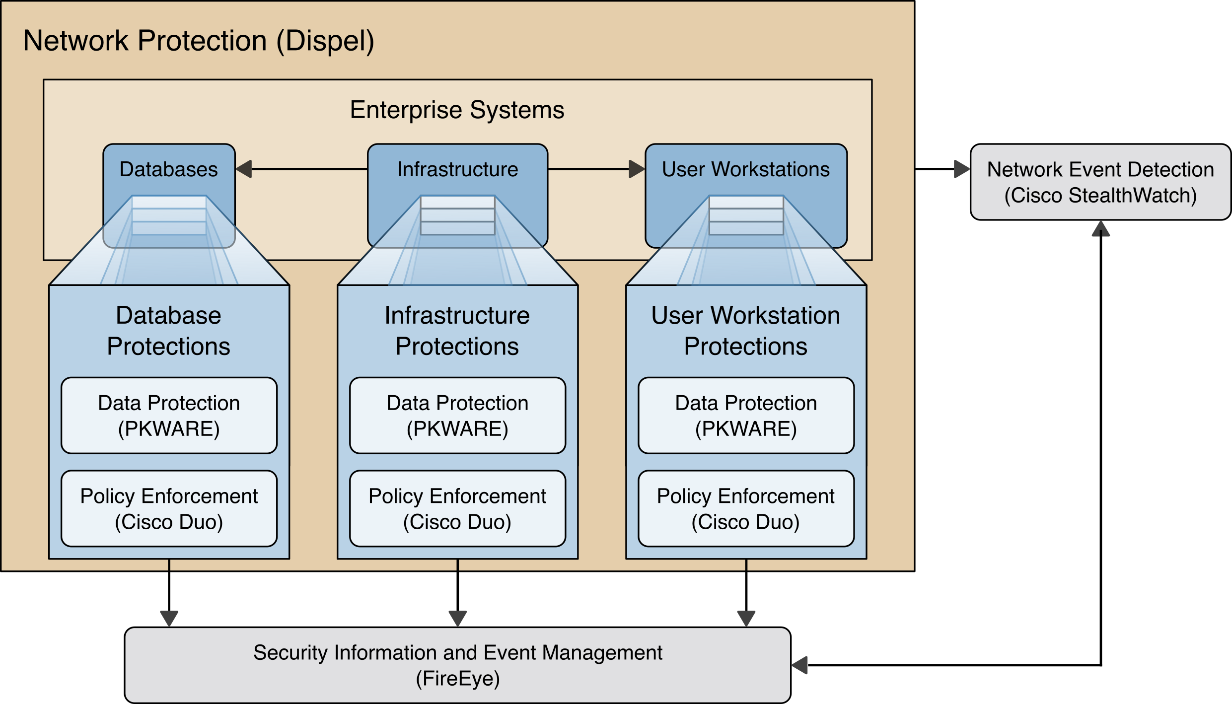
Data Protection (PKWARE) involves maintaining the confidentiality and integrity of proprietary data, even in the event of a security breach or outright theft.
Event Detection and Monitoring (Stealthwatch) focuses on becoming aware of potential intrusions by tracking the events that may indicate a breach of security and alerting the relevant administrators.
Log collection, collation and correlation (FireEye) refers to the proper monitoring of activity on a system, and the analysis of that activity for any potential anomalous patterns or events.
User access controls (Cisco Duo) work to regulate and restrict the level of access different users have, so that they can perform their work without providing unnecessary access that can be turned to more malicious ends.
Network Protection (Dispel) ensures that hosts on the network only communicate in allowed ways, preventing side-channel attacks and attacks that rely on direct communication between hosts. Furthermore, it protects against potentially malicious hosts joining or observing traffic (encrypted or decrypted) traversing the network.
2 Product Installation Guides
This section of the practice guide contains detailed instructions for installing and configuring all of the products used to build an instance of the example solution. This implementation guide is split into sections for each product and integrations between these products, aiming to present a modular architecture where individual capabilities and products can be swapped out or excluded depending on the needs of the organization. Organizations can choose to implement a partial architecture based on their own risk assessments and data protection requirements.
2.1 FireEye Helix
FireEye Helix is a security incident and event management system used for collecting and managing logs from various sources. In this build, Helix is primarily used to manage events and alerts generated by data collected from across the enterprise. This build implemented a cloud deployment of Helix, and as such, much of the documentation provided will be integrating a cloud deployment with various products and components of the enterprise.
In this setup, we detail the installation of a communications broker which will be used to collect logs from the enterprise and forward them to the cloud deployment. This installation took place on a CentOS 7 Virtual Machine.
2.1.1 Installing the Communications Broker
Acquire the Helix Communications Broker for CentOS 7.
Navigate to the folder containing the installer and run the following.
> sudo yum localinstall ./cbs-installer_1.4.2-9.x86_64.rpm
Log on to the Helix web console.
Navigate to Dashboards > Operational.
Click Download Certificate.
Click Download. This will download a “bootstrap.zip” file.
Copy the zip file to the Helix Communications Broker certificate directory.
> sudo cp bootstrap.zip /opt/tap-nxlog/cert
Navigate to the certificate directory.
> cd /opt/tap-nxlog/cert
Extract the zip file you just copied.
> sudo unzip ./bootstrap.zip
If prompted, select “Yes” to overwrite any previous certificate files.
Navigate to one folder above.
> sudo cd ..
Run the setup script.
> sudo ./setup.sh
Enter the name of the CentOS machine.
Enter the receiver URL provided in the Helix welcome email.
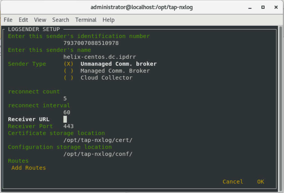
Select Add Routes and press Enter.
Select syslog.
Select tcp.
Select the IP address of the machine where logs should be sent.
Enter 512 for the port number where logs should be sent.
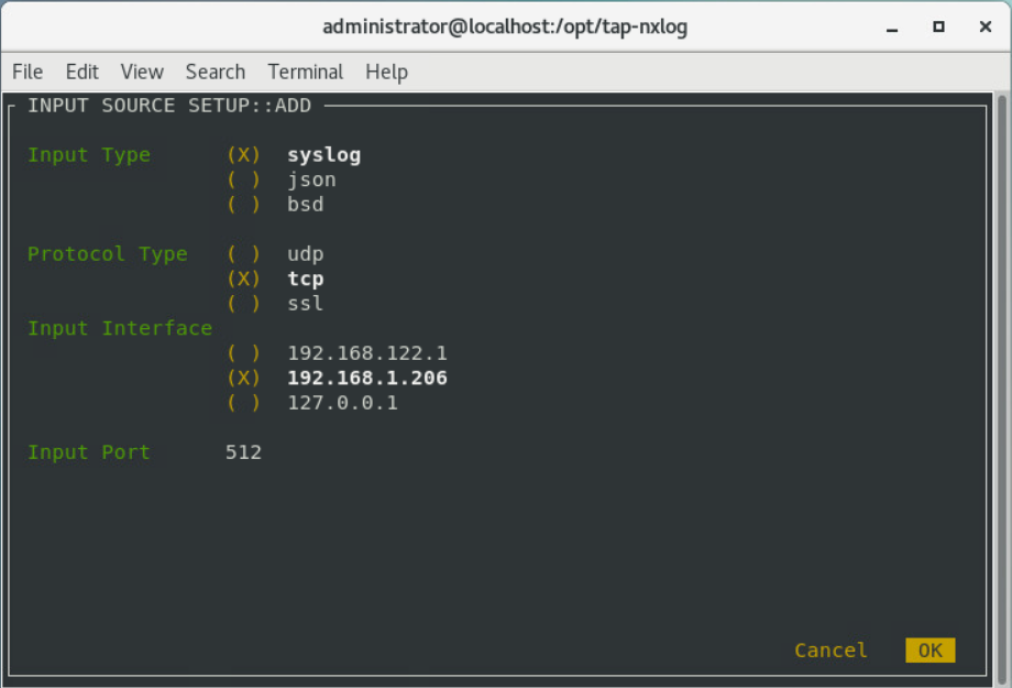
Select OK and press Enter.
Review the configuration, then select OK and press Enter.
2.1.2 Forwarding Event Logs from Windows 2012 R2
Acquire nxlog-ce-2.10.2150.msi from http://nxlog.org/products/nxlog-community-edition/download.
Run nxlog-ce-2.10.2150.msi.
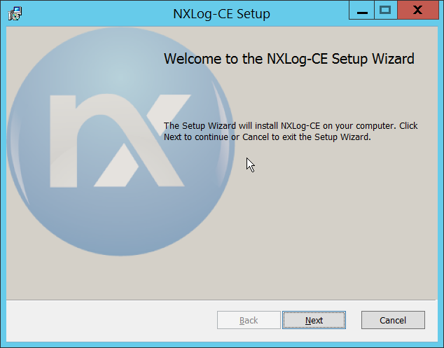
Click Next.
Check the box next to I accept the terms in the License Agreement.
Click Next.
Click Next.

Click Install.
Click Finish.
Navigate to C:\Program Files (x86)\nxlog\conf and open nxlog.conf.
Copy the nxlog.conf file provided below.
Panic Soft
#NoFreeOnExit TRUE

            define ROOT C:\\Program Files (x86)\\nxlog
define CERTDIR %ROOT%\\cert
define CONFDIR %ROOT%\\conf
define LOGDIR %ROOT%\\data
define LOGFILE %LOGDIR%\\nxlog.log
LogFile %LOGFILE%

 Moduledir %ROOT%\\modules
CacheDir %ROOT%\\data
Pidfile %ROOT%\\data\\nxlog.pid
SpoolDir %ROOT%\\data

<Extension \_syslog>
    Module xm_syslog
</Extension>

<Input in>
    Module im_msvistalog
# For windows 2003 and earlier use the following:
# Module im_mseventlog
</Input>

<Output out>
    Module om_tcp
    Host 192.168.1.206
    Port 512
    Exec to_syslog_snare();
</Output>

<Route 1>
    Path in => out
</Route>
Restart the nxlog service.
You can verify that this connection is working by checking the logs in data\nxlog.log, and by noting an increase in events on the Helix Dashboard.
2.2 PKWARE PKProtect
This installation and configuration guide for PKWARE PKProtect uses a physical PKWARE server, and as such will not delve into the installation of server components. In this guide, PKWARE is used to automatically perform data inventory and data protection functions.
2.2.1 Configure PKWARE with Active Directory
Login to the PKWARE web portal using the provided administrative credentials.
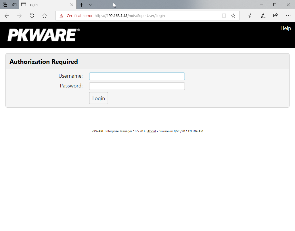
Once logged in, you can and should change the password to this administrative account by clicking Change Password in the top right corner.
Navigate to System > Domain.
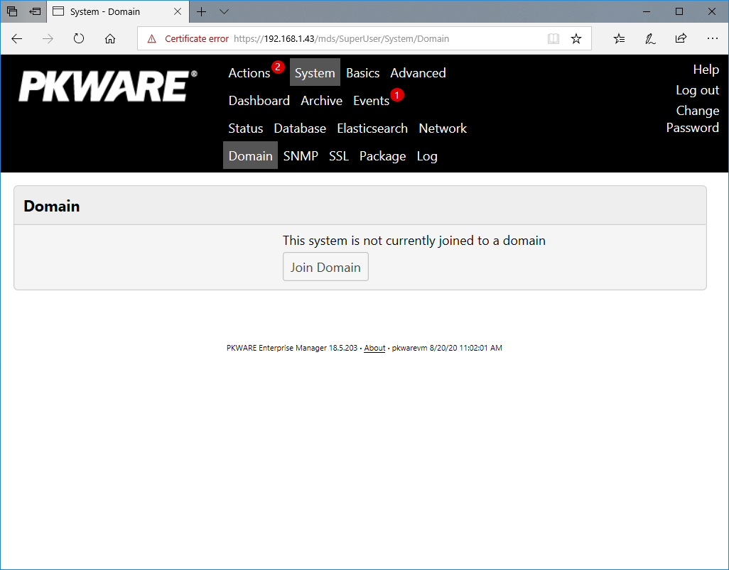
Click Join Domain.
Enter the Kerberos Realm, NetBIOS Domain, as well as the username and password of an administrative user on the domain.
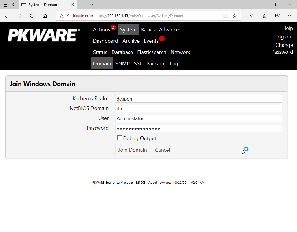
Click Join Domain.
2.2.2 Create a New Administrative User
Navigate to Advanced > Admins.
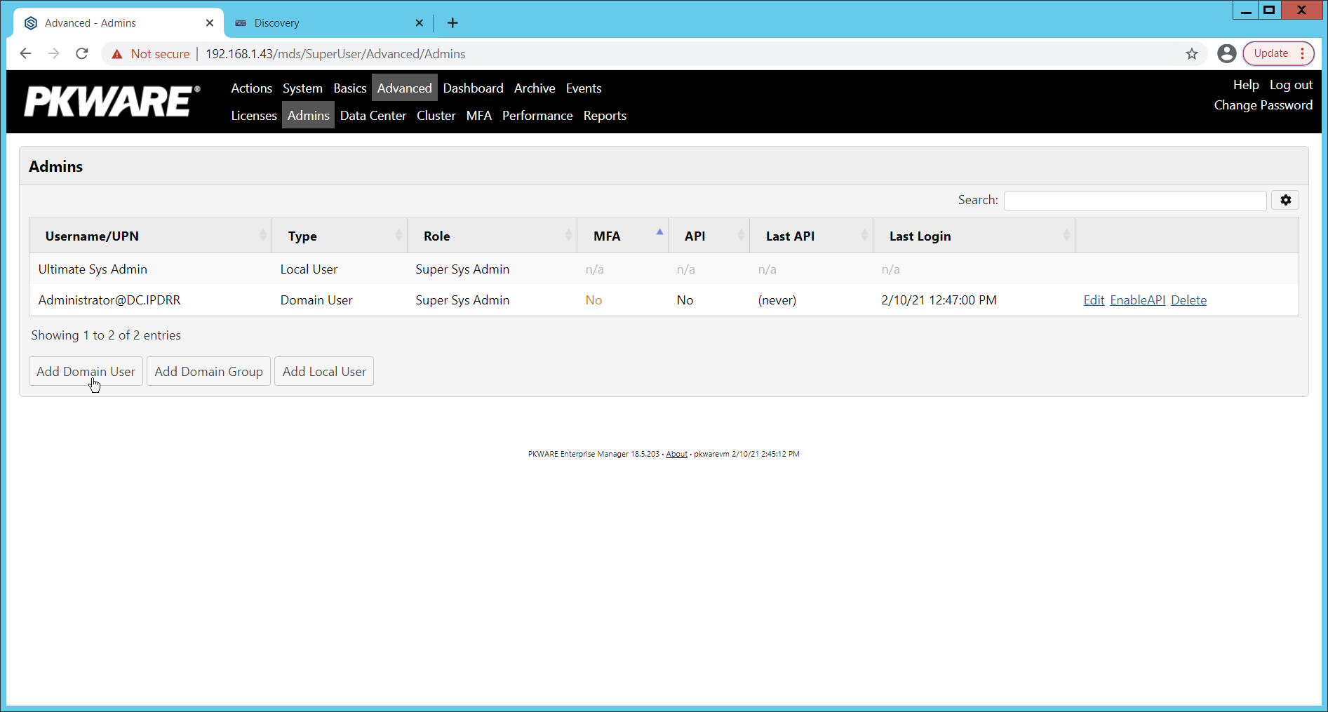
Click Add Domain User.
Enter the username of a user on the domain that should be able to login through the PKWARE management portal (this is meant for administrators only).
Select the level of permissions the user should have.
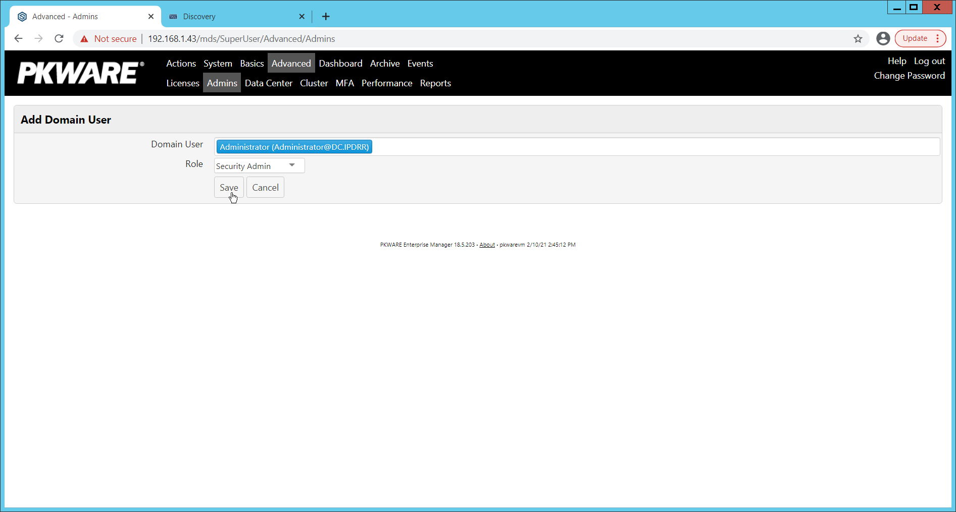
Click Save.
2.2.3 Install Prerequisites
If needed for your environment, you may need to install certificates locally before agents can connect to PKProtect - ask your PKProtect representative if this is necessary for your environment.
Double click the certificate you wish to install.
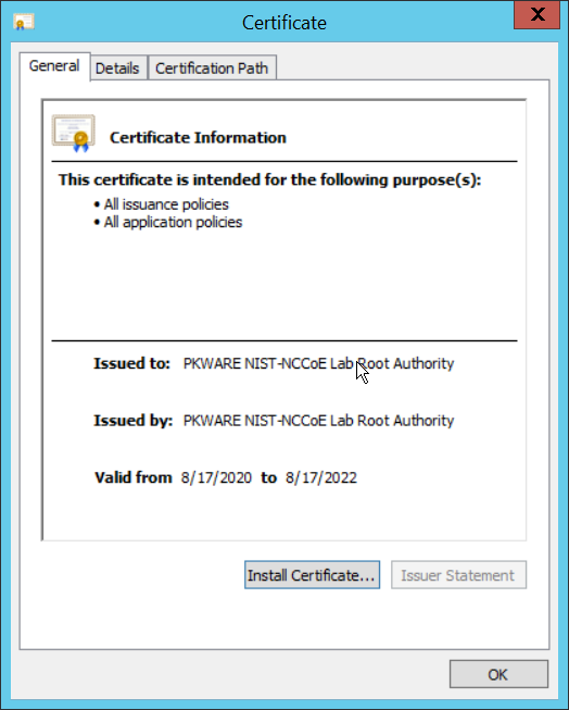
Click Install Certificate.
Select Current User.
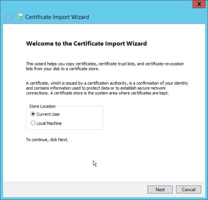
Click Next.
Click Browse.
Select Trusted Root Certification Authorities.
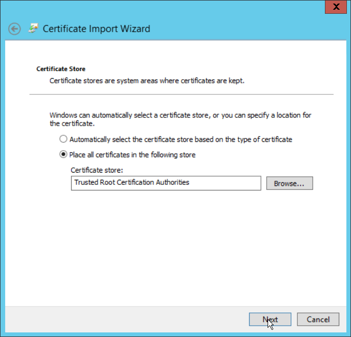
Click Next.
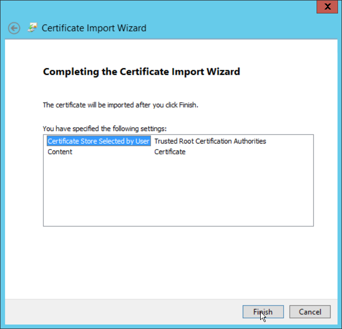
Click Finish.

Click OK.
Repeat steps 1 through 10 but select Personal instead of Trusted Root Certification Authorities.
Repeat steps 1 through 11 for each certificate which needs to be installed.
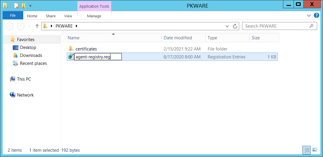
Rename agent-registry.txt to agent-registry.reg.
Double click the file (must have administrator privileges).
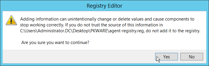
Click Yes.
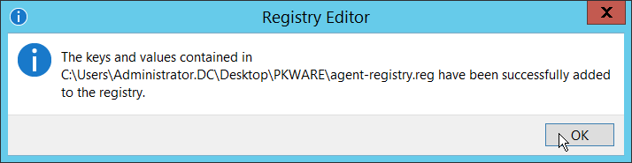
Click OK.
Restart the machine to apply these changes.
2.2.4 Install the PKProtect Agent
Run the PKProtect Installation executable.
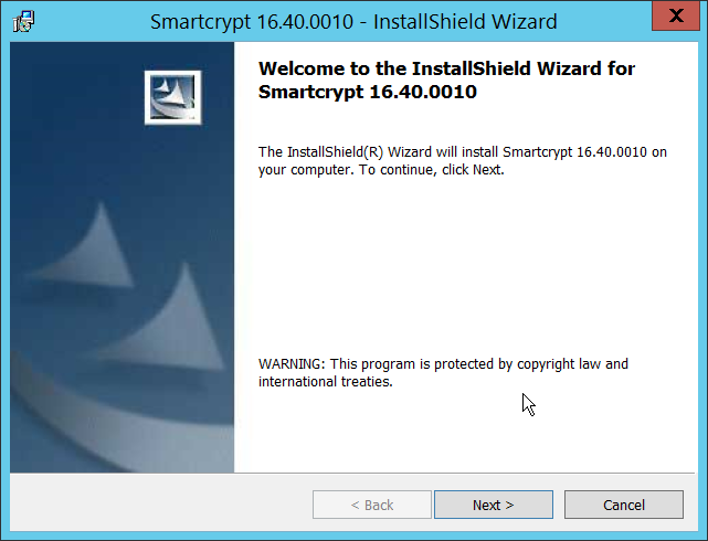
Click Next.
Select I accept the terms in the license agreement.

Click Next.
Select Typical.
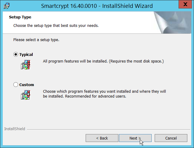
Click Next.
Click Install.
Click Finish.
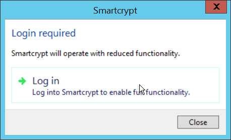
If a window to login is not automatically shown, you can right click the PKProtect icon in the Windows taskbar and click Log in. If a window is automatically shown, click Log in.
Login using the username of the account in the domain, in email format (such as administrator@domain.id).
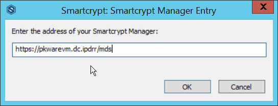
Enter the address of the PKWARE server.
The PKWARE agent will now run in the background.
2.2.5 Configure Discovery and Reporting
On the PKWARE dashboard, log in as an administrative user, and navigate to Archive > Discovery.
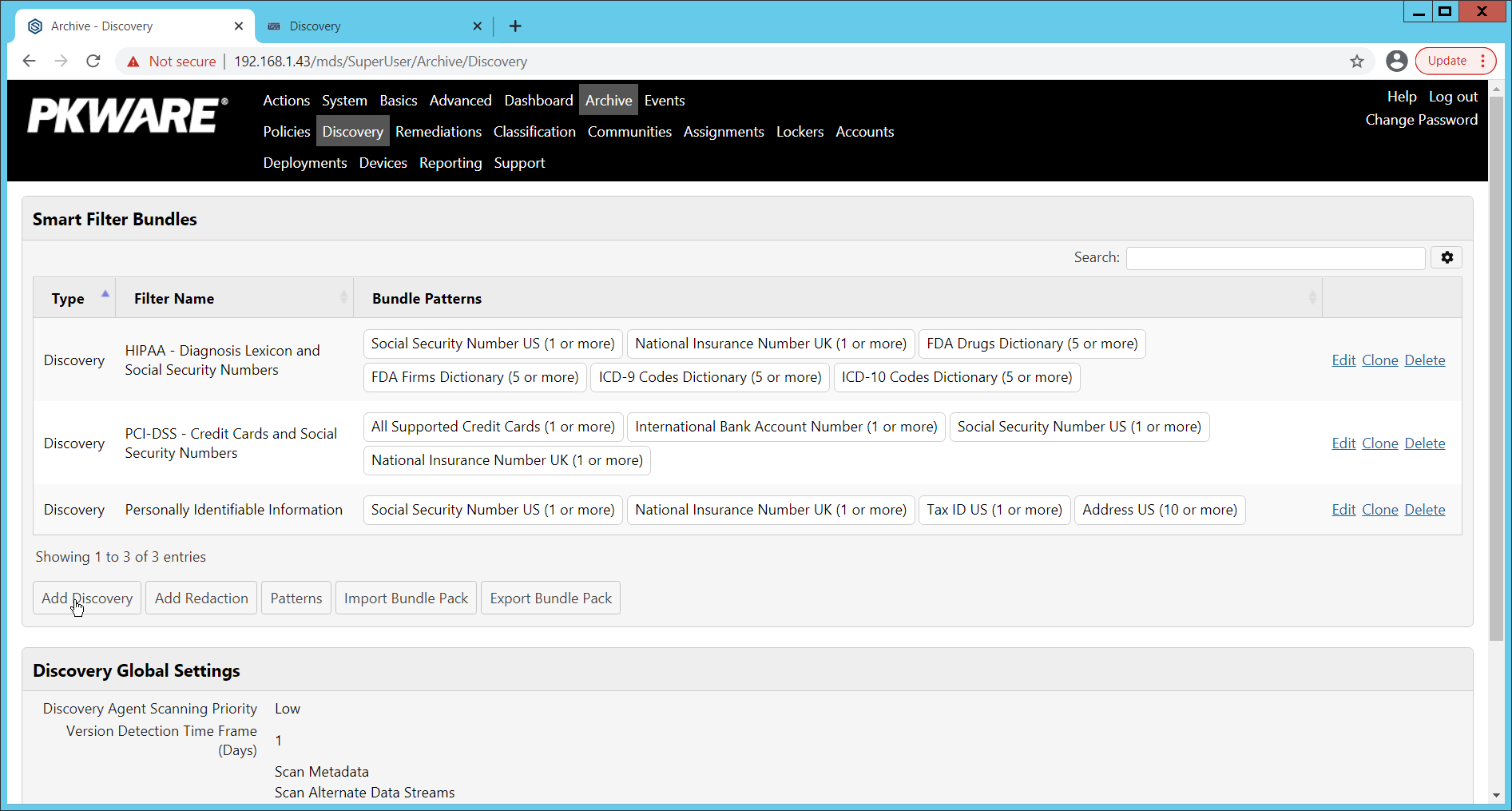
Click Add Discovery.
Enter a name for the discovery rule.
Select a pattern for the rule to discover. In this case, we are setting up a rule to detect social security numbers in files for reporting/remediation.
The Threshold field refers to how many of those patterns must be present in a document for the rule to be applied.
Click Save.
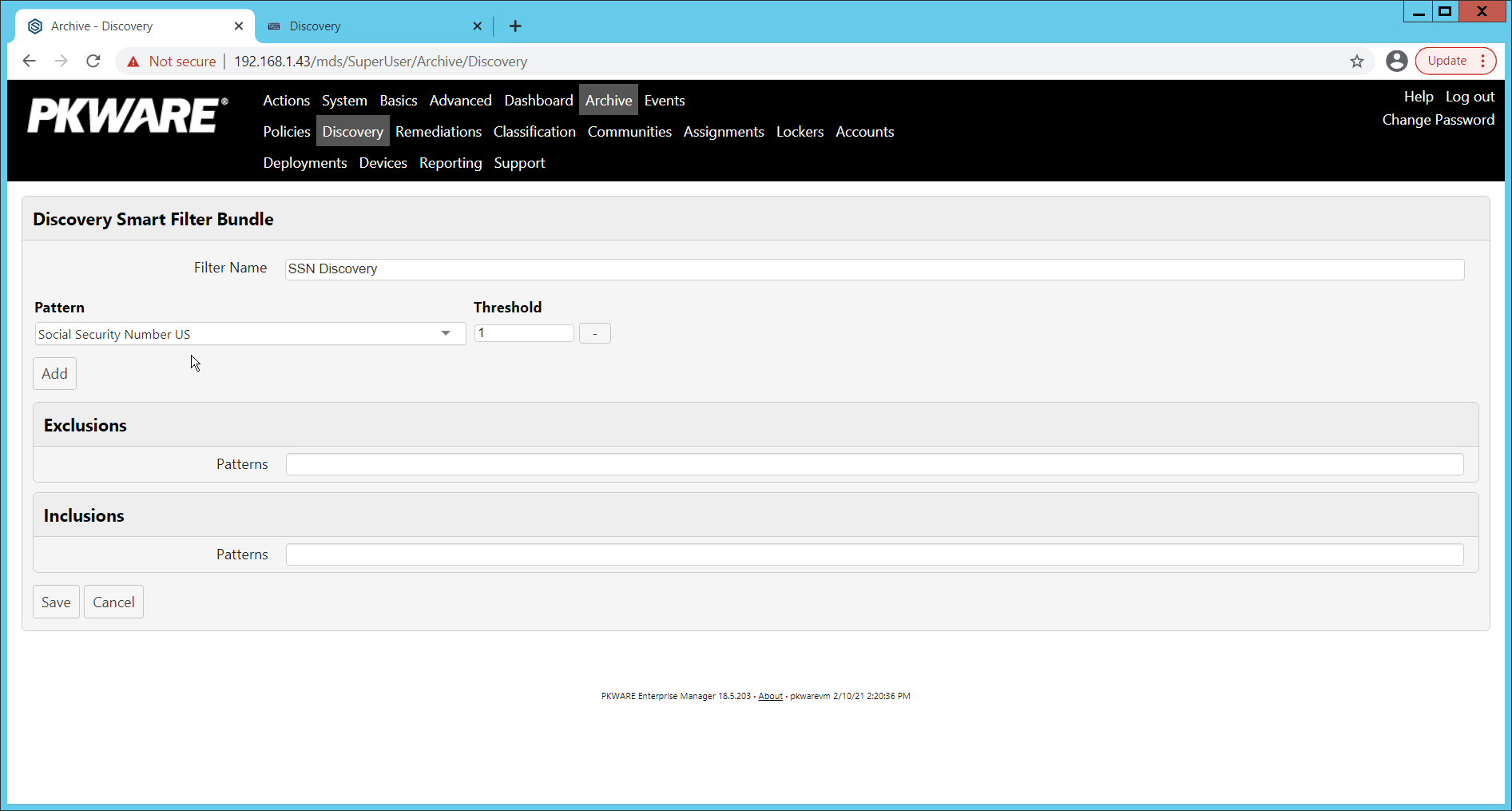
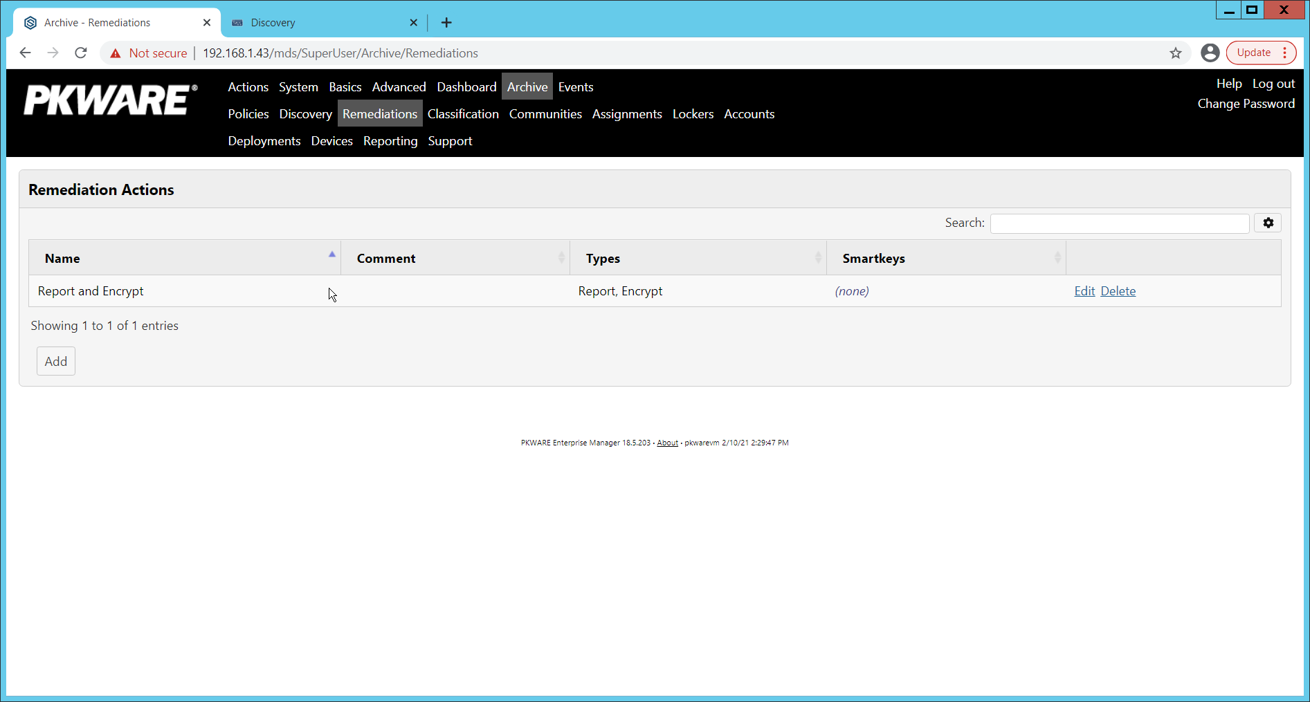
Navigate to Archive > Remediations.
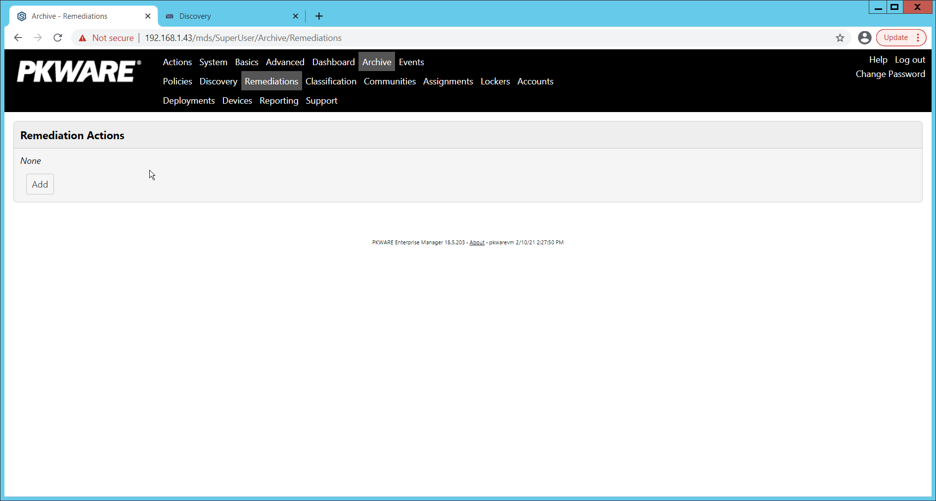
Click Add.
Enter a name for the remediation.

Check the box next to Report Discovery Events.
Check the box next to Encrypt.
Ensure that AES (256-bit) is selected.
Click Save.
Navigate to Archive > Assignments.
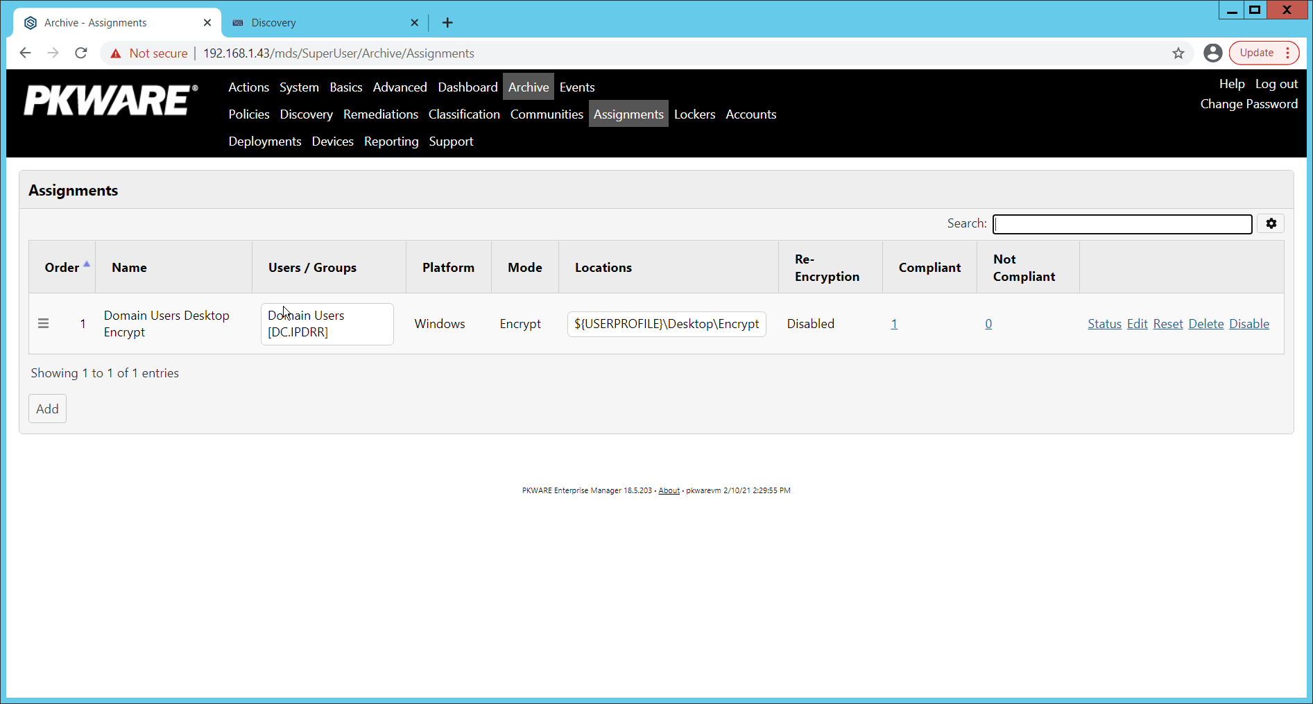
Click Add.
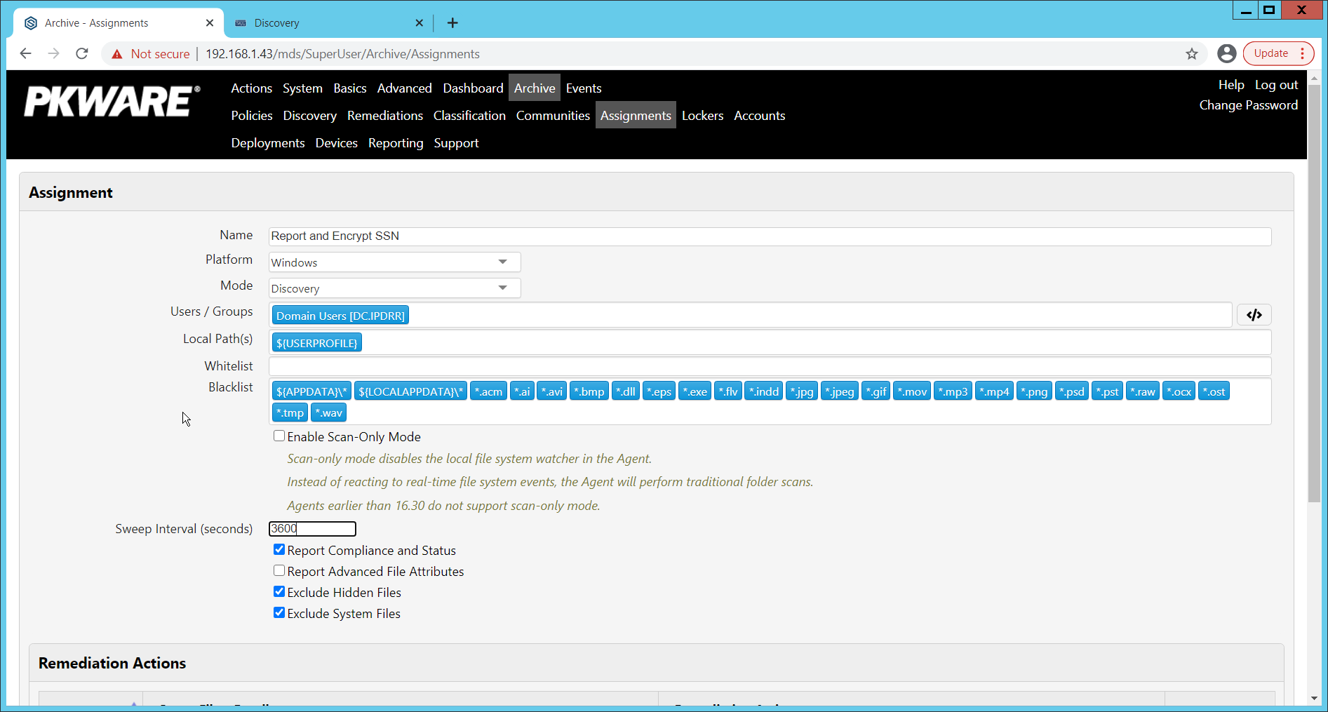
Enter a Name for the Assignment.
Select the Platform for this assignment to run on.
Select Discovery for the Mode.
Enter the names of the Active Directory users or groups this rule should apply to.
Enter the folders for this rule to search in Local Paths.
Use Whitelist and Blacklist to specify file types which should or should not be considered.
Enter the interval for this rule to run in Sweep Interval.
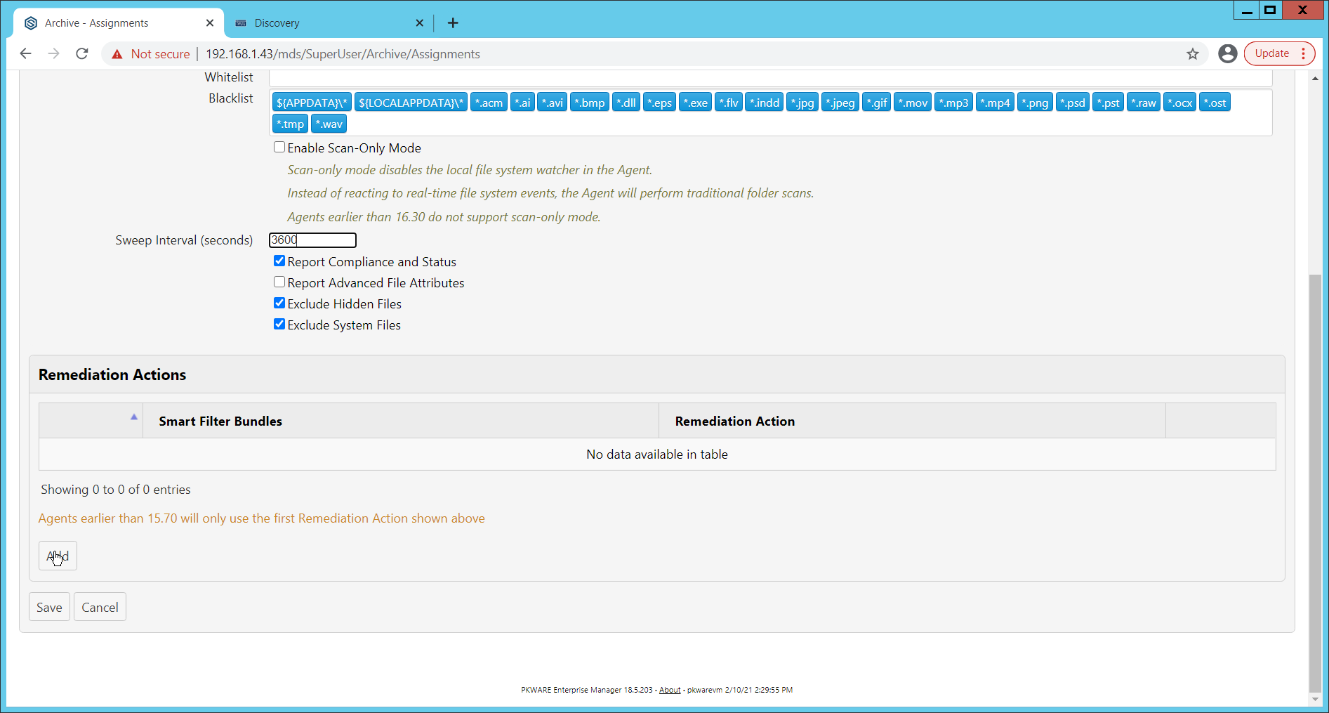
Under Remediation Actions, click Add.
Select the Discovery rule created earlier under Smart Filter Bundles.
Select the Remediation Action created earlier under Remediation Action.
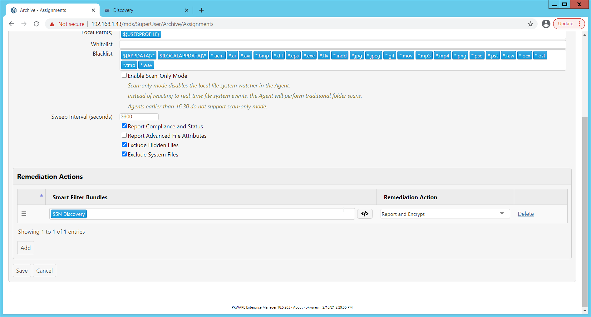
Click Save.
This rule will now run automatically, reporting and encrypting files which match its discovery conditions.
2.3 Cisco Duo
Cisco Duo is a Multi-Factor Authentication and Single Sign-On tool. In this project, Dispel is used to control access to internal systems through virtualization, and Duo is used as a multifactor authentication solution between Dispel and those internal systems. This ensures that even if a Dispel virtual machine becomes compromised, there is still significant access control between that machine and the internal enterprise machines.
In the following section, we demonstrate the installation of Cisco Duo on an internal system in such a way that RDP and local login to that system is protected by multifactor authentication.
2.3.1 Installing Cisco Duo
Begin by logging into the system you wish to protect with Duo.
Then connect to the internet, if not connected already, and go to the Duo Admin login page at https://admin.duosecurity.com/.
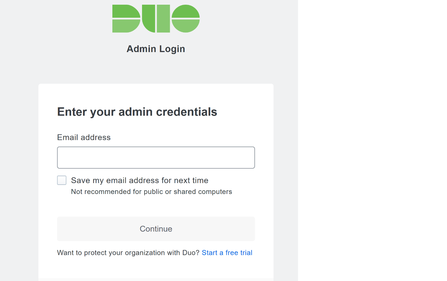
Login with your admin credentials and dual factor authentication to reach the administrator dashboard.
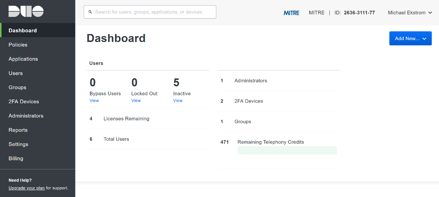
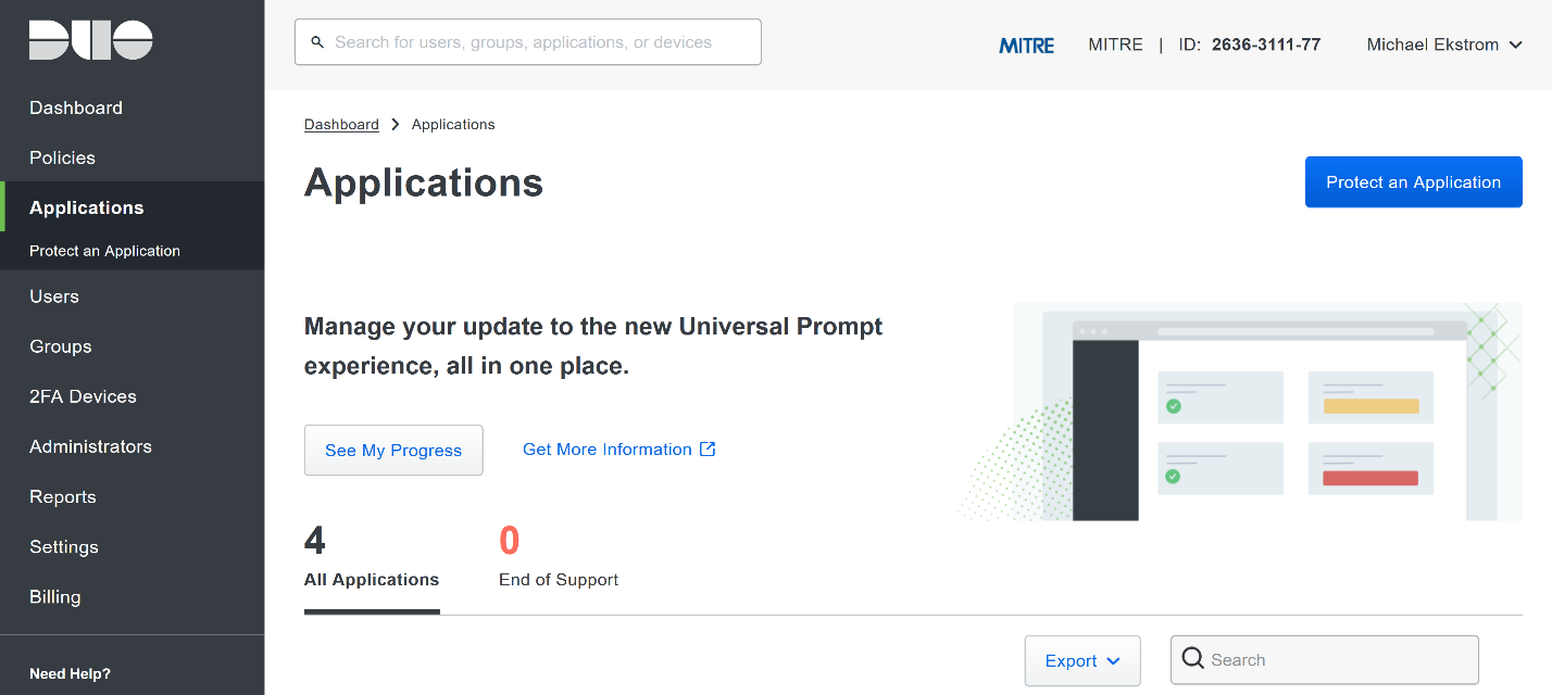
Click Applications in the sidebar.
Click Protect an Application.
Search for, or scroll down to, Microsoft RDP.
Click Protect.
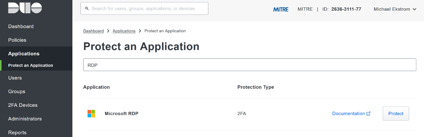
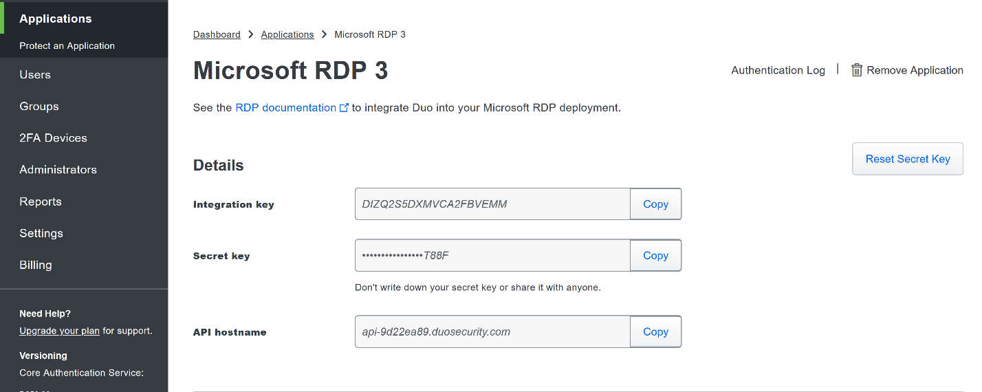
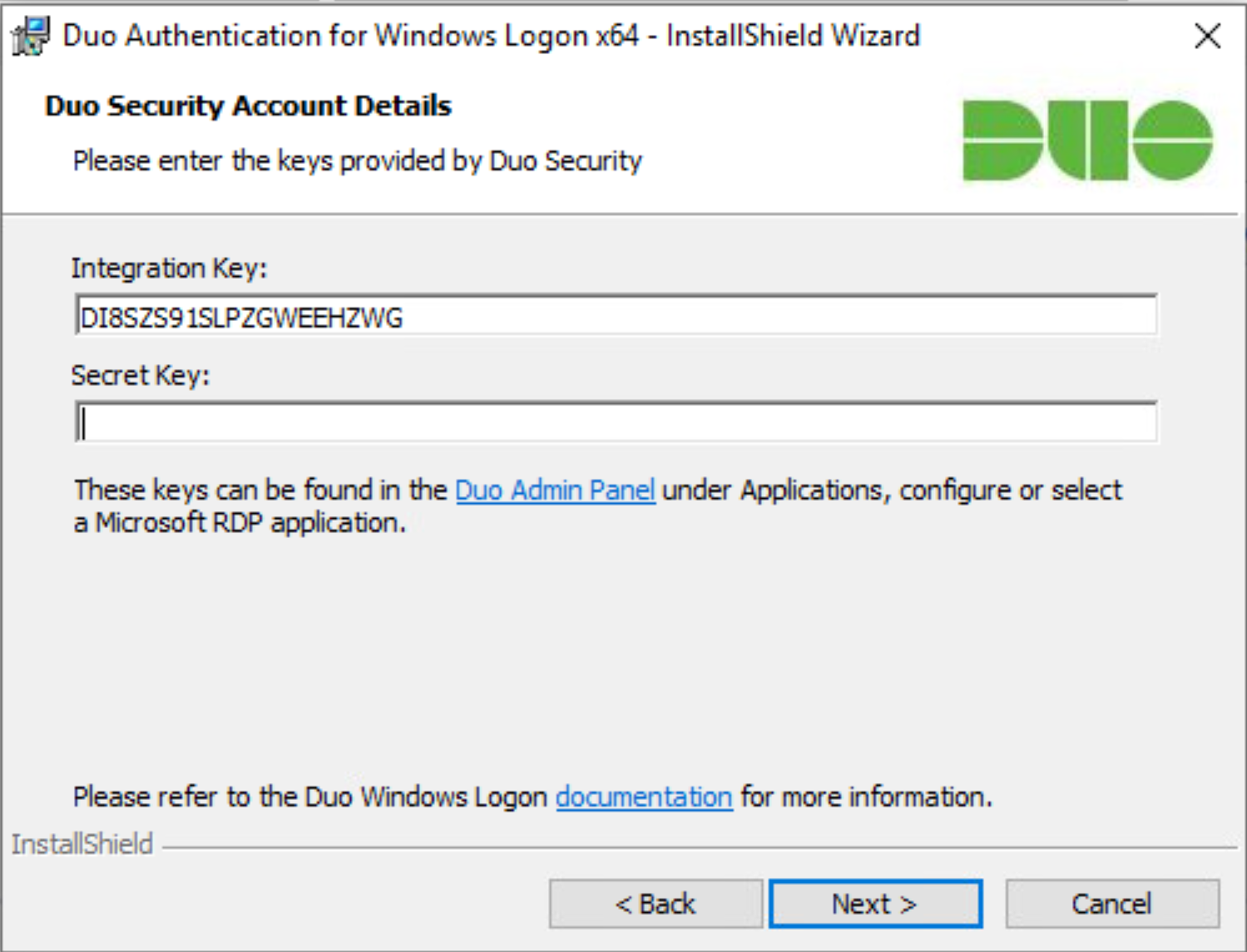
The next screen will provide policy configuration options, as well as the Integration Key, Secret Key, and API hostname, which are required information for the next step. Either keep this window open or copy down those three pieces of information.
Download the Duo Authentication for Windows Logon installer package, located at https://dl.duosecurity.com/duo-win-login-latest.exe.
Run the downloaded EXE file.
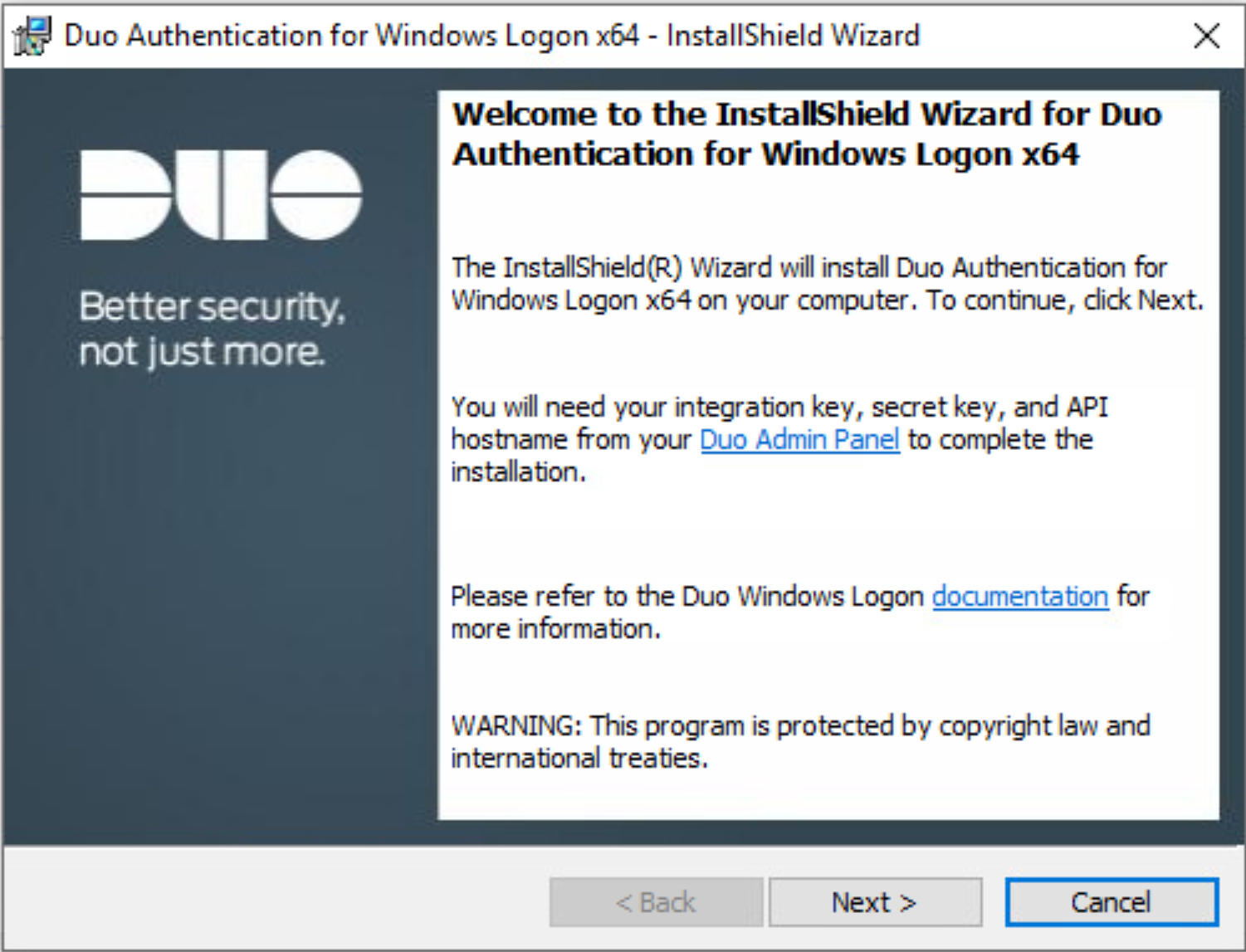
Click Next.
Copy the API Hostname into the labeled field.
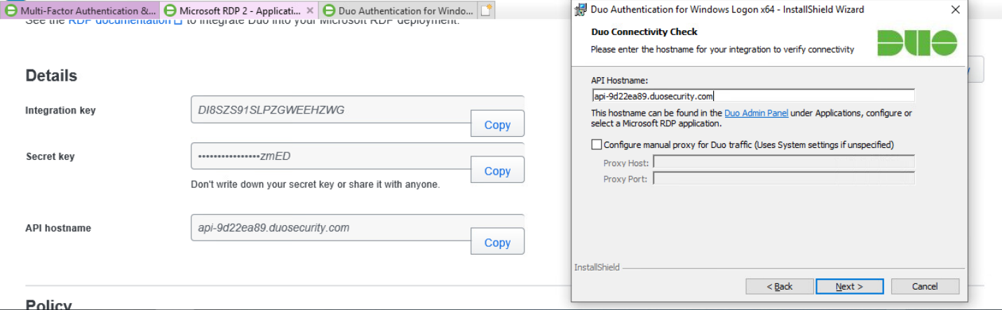
Click Next.
Copy in the Integration and Secret Keys into the relevant fields and click Next.
Click Next.
Configure Duo’s integration options according to the needs of your organization. Note that Bypass Duo authentication when offline will allow users to skip the two-factor authentication when offline, which increases the availability of their files but may increase risk.
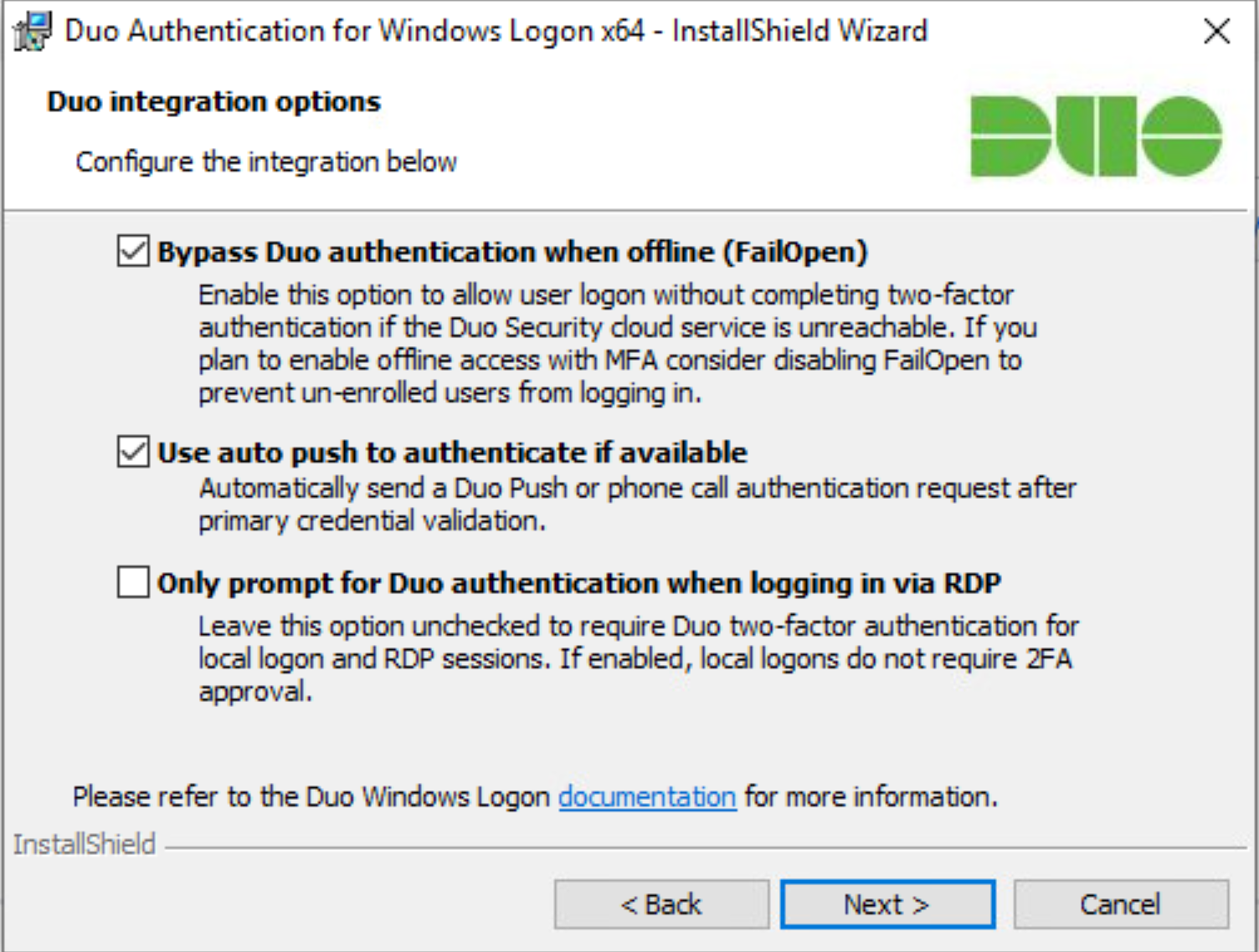
Click Next.
Leave Enable Smart Card support unchecked.
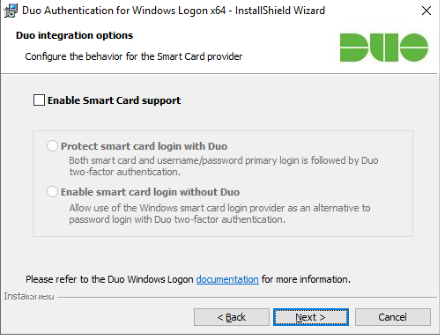
Click Next.
Leave Enable UAC Elevation Protection unchecked.

Click Next.
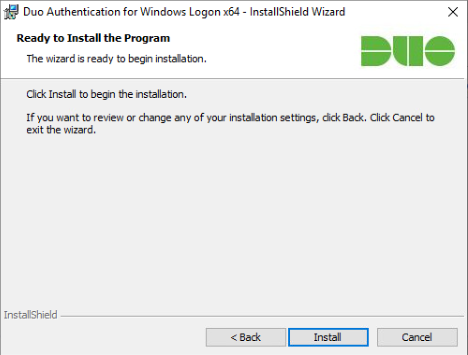
Click Install.
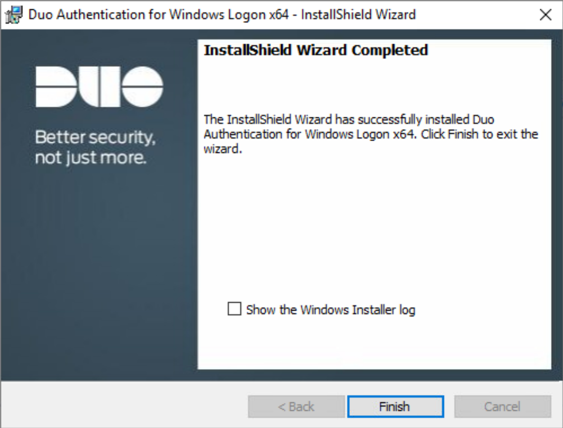
Click Finish.
Installation should now be complete. Users registered on the Duo Dashboard with a linked phone will be allowed access to the system.
2.3.2 Registering a Duo User
Login to the Duo Admin Dashboard.
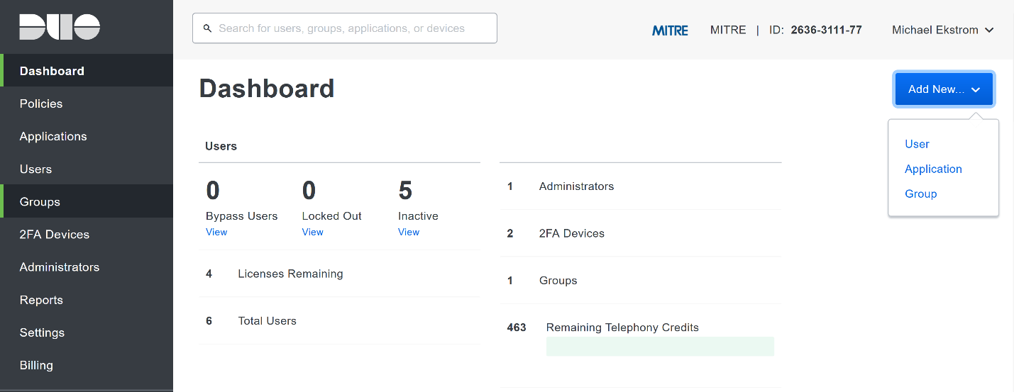
Click Add New > User from the drop-down menu on the right.
Enter a username for the user.
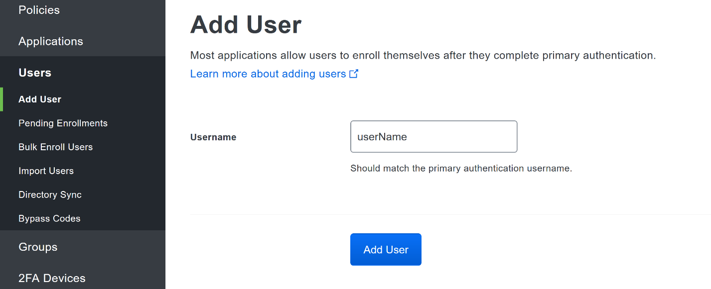
Click Add User.
This will lead you to that user’s information page, where additional information (full name, email, phone number) and Duo authenticators (phone numbers, 2FA hardware tokens, WebAuthn, etc.) can be associated with that username. Note: A user will not be able to log into a Duo protected system unless the user is registered and has an authentication device associated with their username.
2.4 Cisco Stealthwatch
This section will describe the setup and configuration of Cisco Stealthwatch, a network monitoring solution. Cisco Stealthwatch provides insight into the networking activity of the organization, allowing for the detection of malicious network activity, as well as the ability to review user activity for the source of breaches, and intentional or unintentional data egress. This guide assumes the use of the Stealthwatch virtual machines.
2.4.1 Configure Stealthwatch Flow Collector
Log in to the console of the Stealthwatch Flow Collector.
Enter the networking information for the machine.
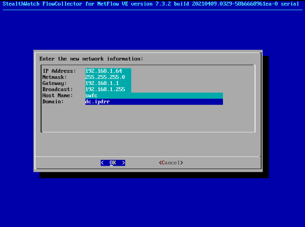
Select OK and press Enter.
Navigate the menu to highlight Management and Select.
Confirm the settings.
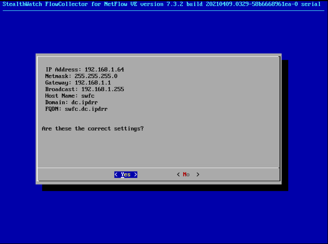
Select Yes and press Enter.
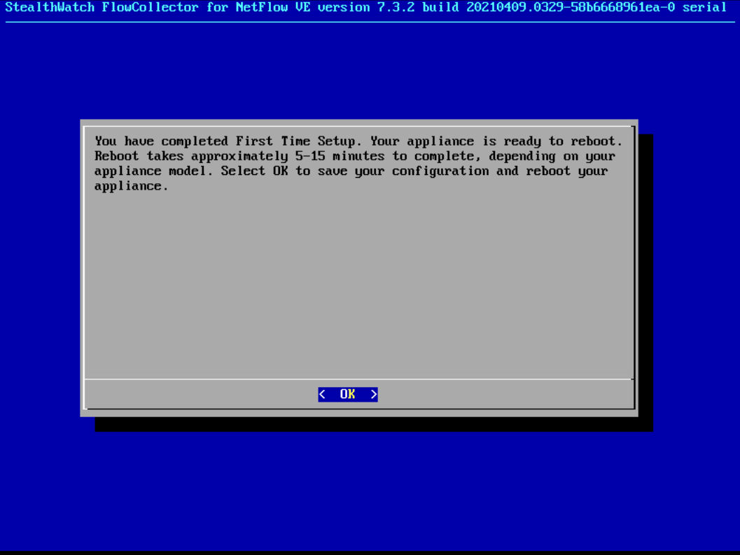
Select OK and press Enter.
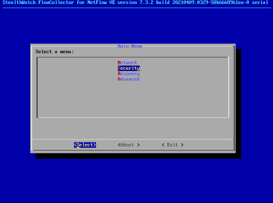
Once the machine restarts, navigate to Security, and press Enter.
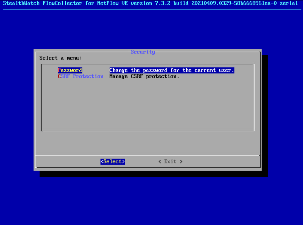
Select Password and press Enter.
Change the password from the default password to a secure password.
2.4.2 Configure Stealthwatch Management Console
Log in to the console of the Stealthwatch Management Console.
Enter the networking information for the machine.
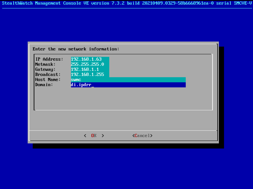
Select OK and press Enter.
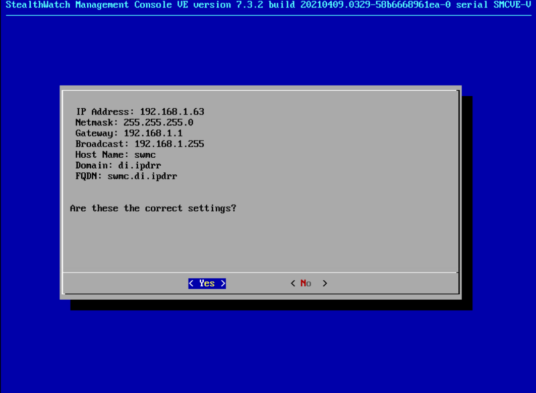
Select Yes and press Enter.
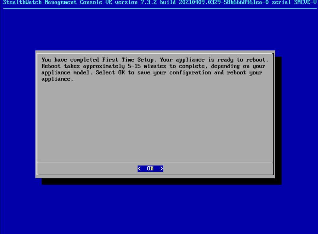
Select OK and press Enter.
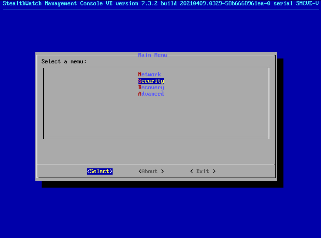
Once the machine restarts, navigate to Security, and press Enter.
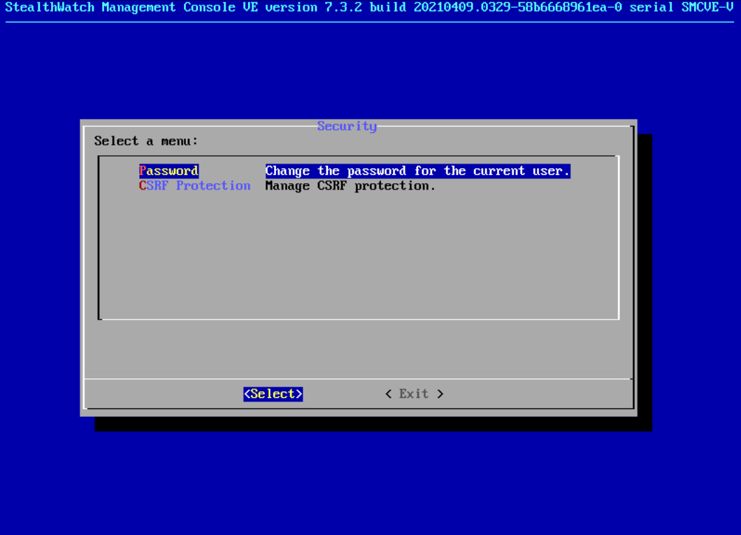
Select Password and press Enter.
Change the password from the default password to a secure password.
Navigate to the Stealthwatch Management Console from a web browser. The URL will be https://<<address of Stealthwatch MC>>.
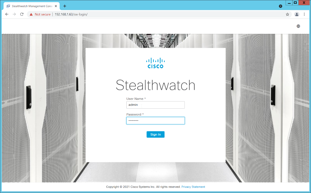
Login using the default username and password (should be provided by product vendor).
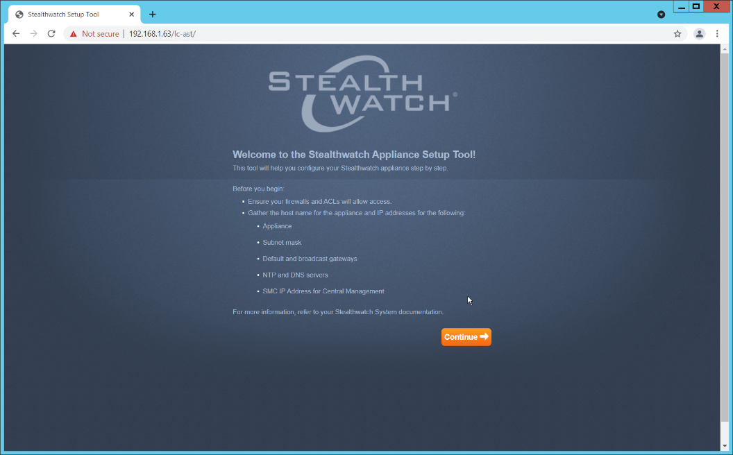
Click Continue.
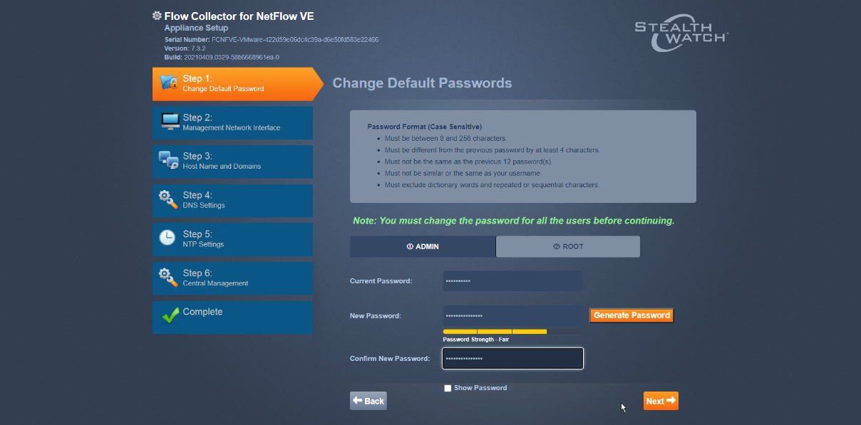
Change the password for the admin account (this is the account used to log in to the web interface).
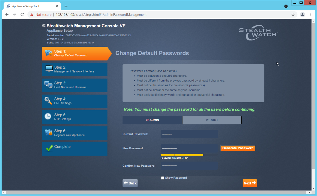
Click Next.
Change the password for the root account (this is the account used to log in to the command line console).
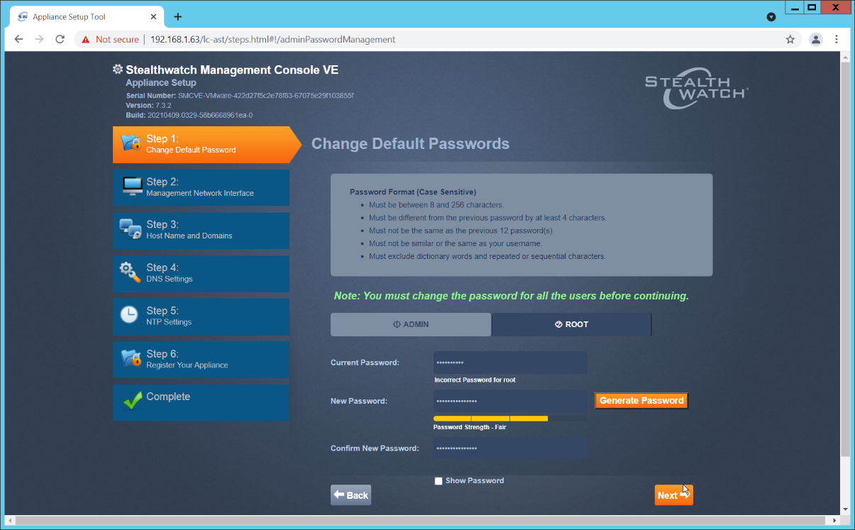
Click Next.
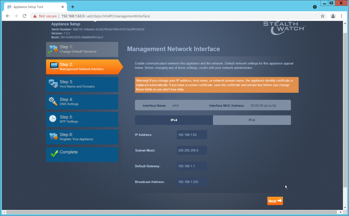
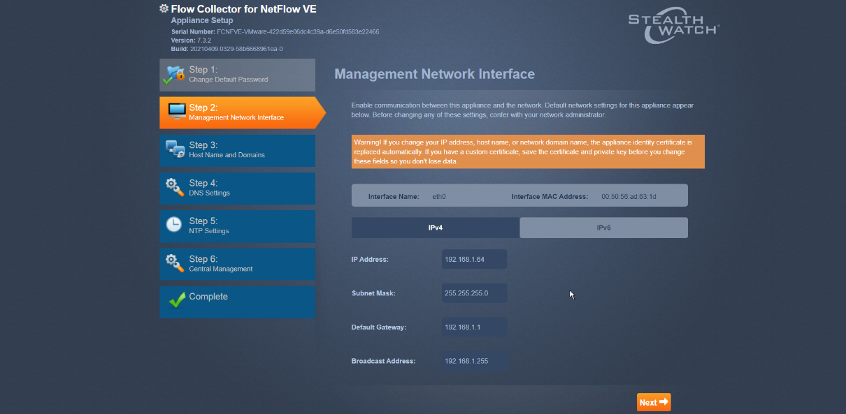
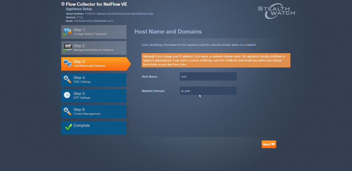
Confirm the networking information is correct and click Next.
Enter the domain for Stealthwatch, and the IP addresses Stealthwatch will be monitoring.
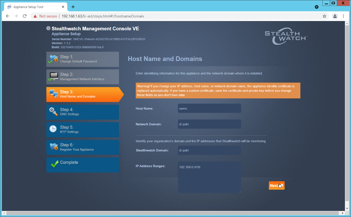
Click Next.
Add the DNS server(s) Stealthwatch should be using.
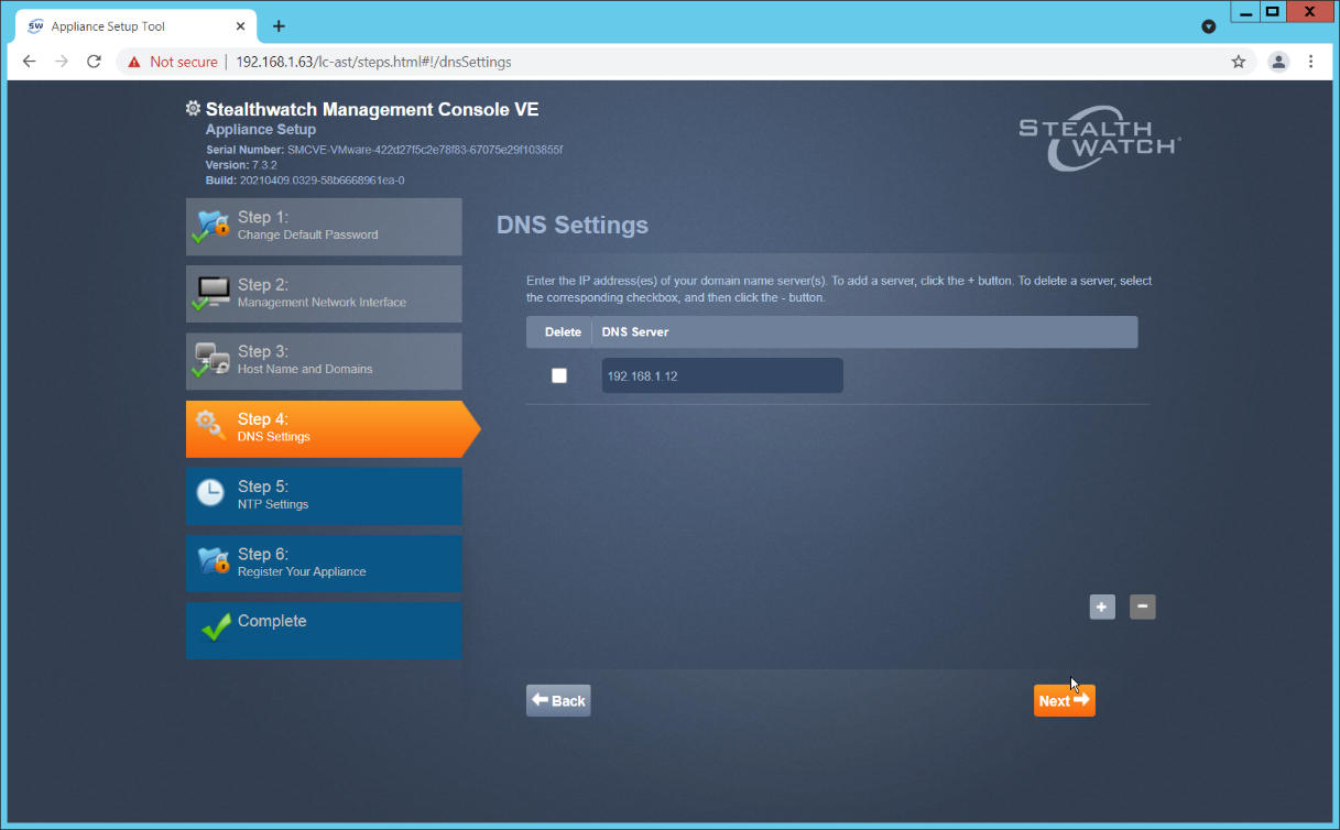
Click Next.
Enter the NTP server(s) Stealthwatch should use.
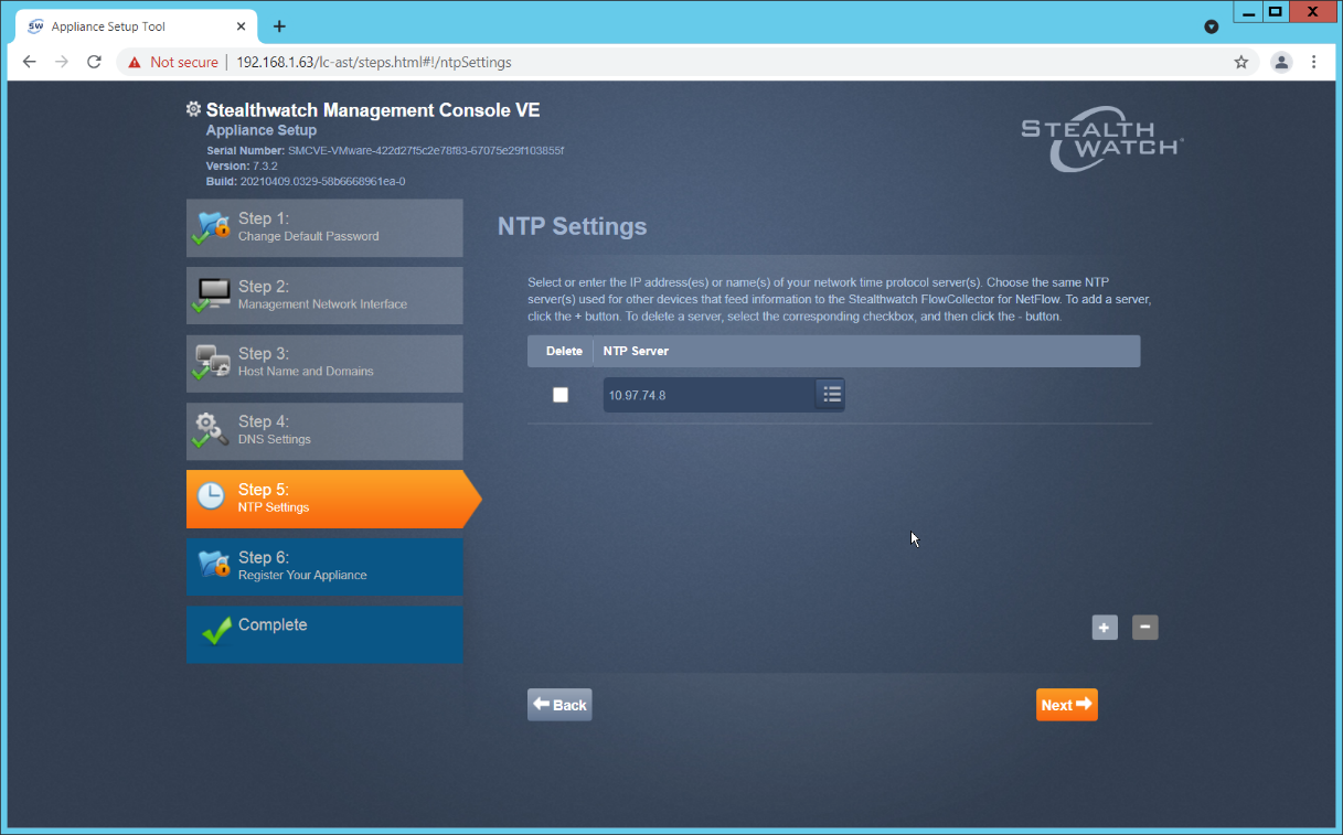
Click Next.
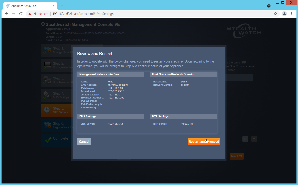
Click Restart and Proceed.
image72|
After it restarts, log in again, and click Continue.
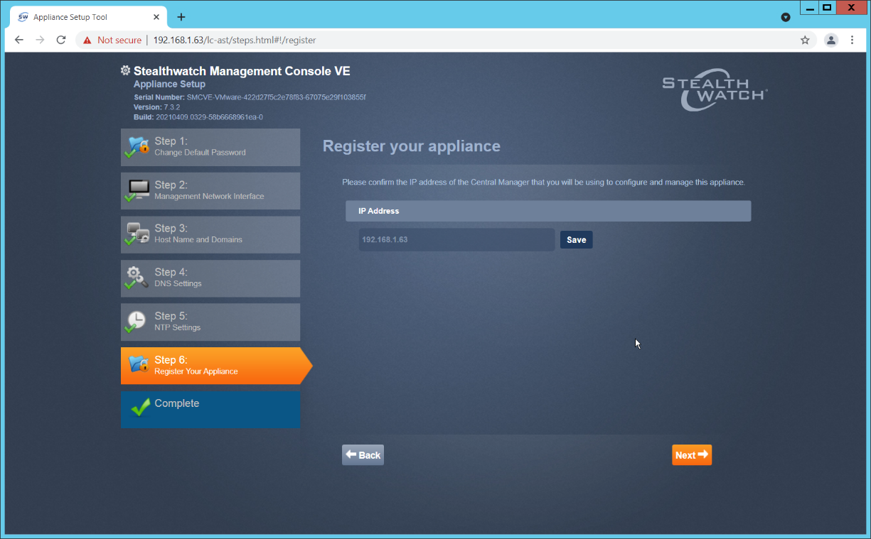
Confirm the IP address is correct and click Next.
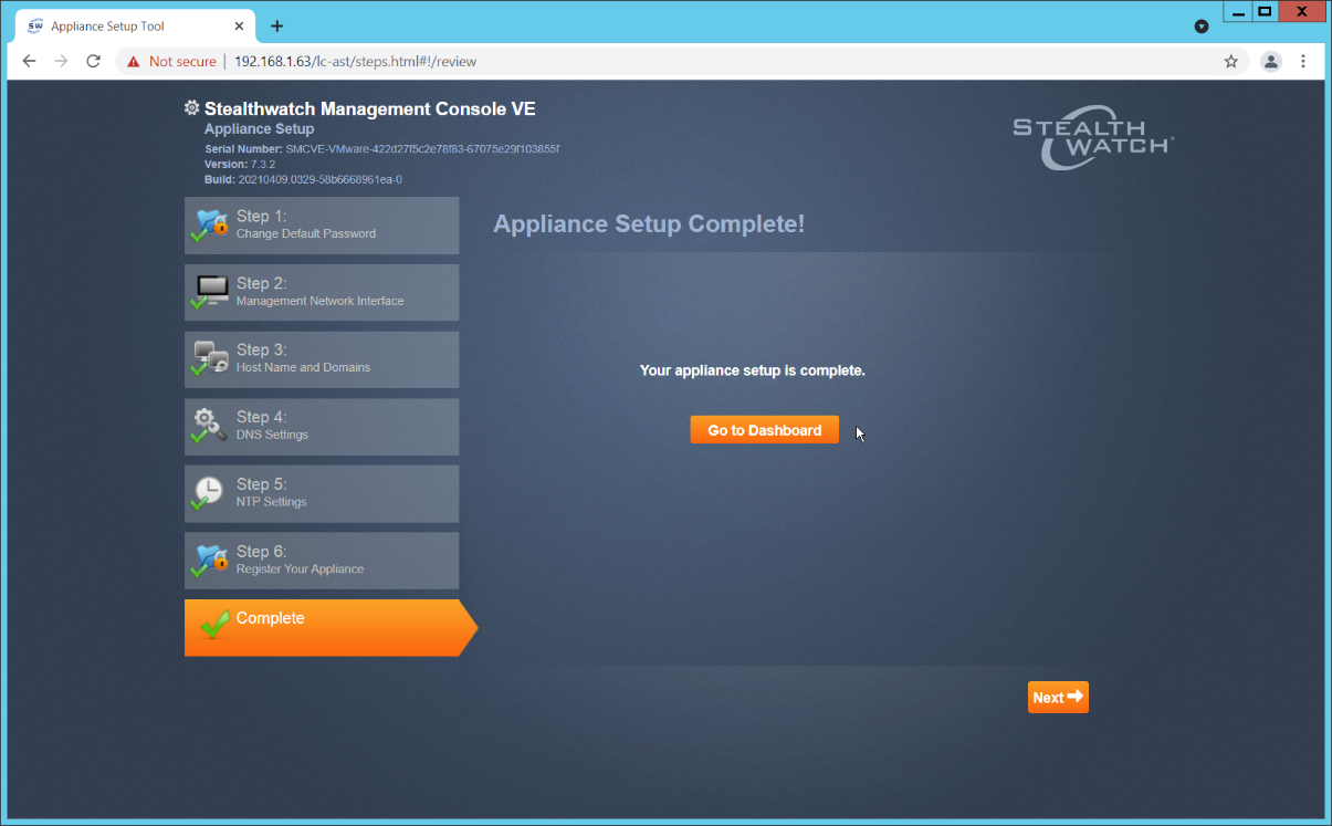
Click Go to Dashboard.
2.4.3 Add Stealthwatch Flow Collector to the Management Console
Navigate to the Stealthwatch Flow Collector Console from a web browser. The URL will be https://<<address of Stealthwatch FC>>.
Login using the default username and password (should be provided by product vendor).
Click Continue.
Change the passwords for the admin and root accounts.
Click Next.
Confirm the networking information is correct and click Next.
Confirm the domain name for Flow Collector is correct.
Click Next.
Add the DNS server(s) Stealthwatch should be using.
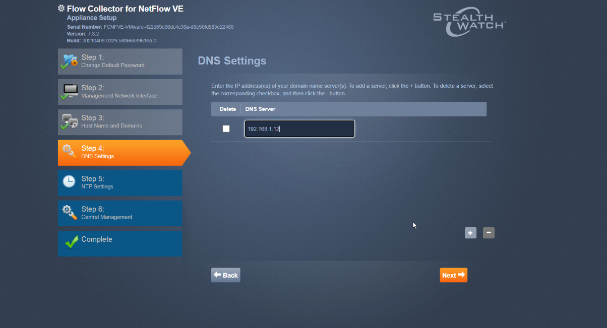
Click Next.
Enter the NTP server(s) Stealthwatch should use.
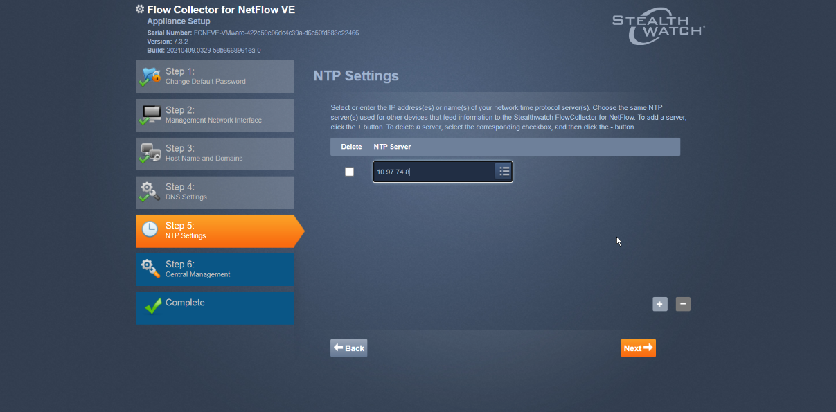
Click Next.
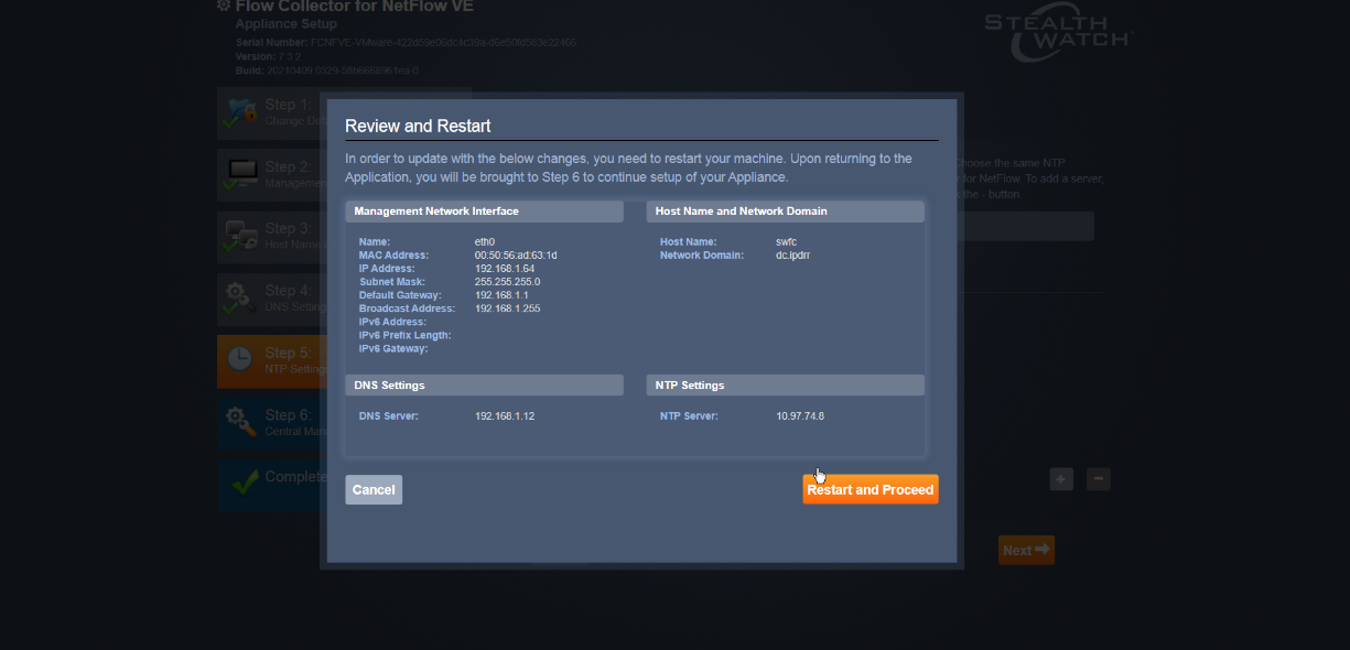
Click Restart and Proceed.
After it restarts, log in again, and click Continue.
Enter the IP of the Stealthwatch Management Console.
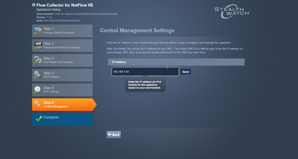
Click Save.
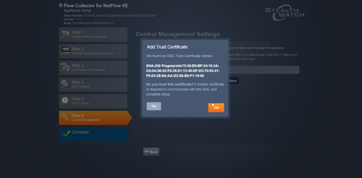
Accept the certificate by clicking Yes.
Enter the username and password for the Stealthwatch Management Console.
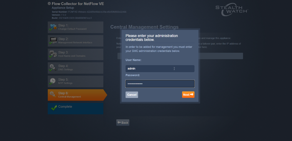
Click Next.
Enter the Domain and Flow Collection Port.
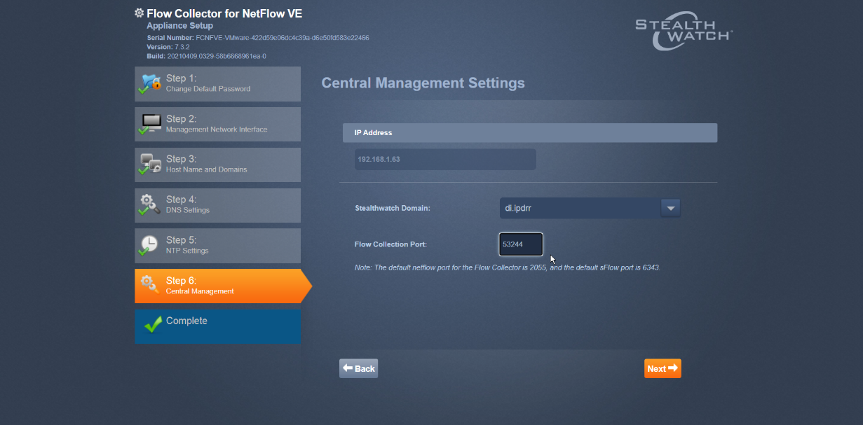
Click Next.
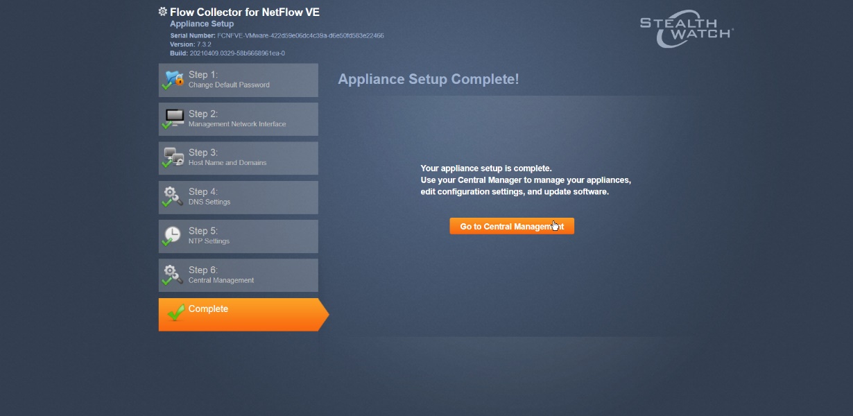
Click Go to Central Management to be redirected to the dashboard.
2.5 Dispel
Dispel is a network protection and user access tool that we used to provide a Virtual Desktop Infrastructure (VDI) capability. A typical deployment of Dispel is done in a largely managed fashion, with a specific deployment being tailored to a network setup. The deployment in the NCCoE laboratory may not be the best setup for any given network. The NCCoE deployment was done on an Ubuntu host with north and south-facing network interfaces, placing the device in-line between the enterprise systems and the external network.
2.5.1 Installation
Deploy an Ubuntu machine with the provided specifications, ensuring that a provided ISO is attached to the device.
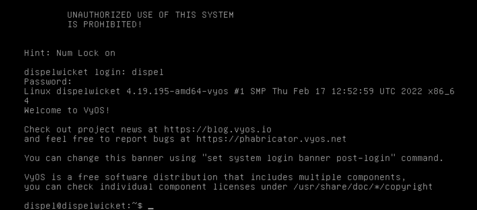
Login with username “dispel” and the password provided.
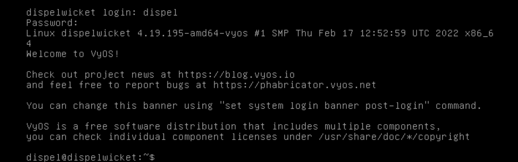
Begin the installation process.
> install image

Press enter on the following three prompts, modifying any default options as desired.
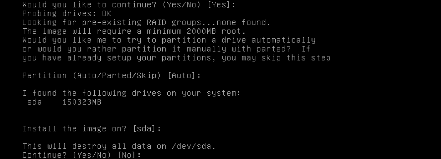
Type
yesbefore pressing enter to rewrite the current volume.
Press enter on the remaining prompts, modifying any default options as desired.
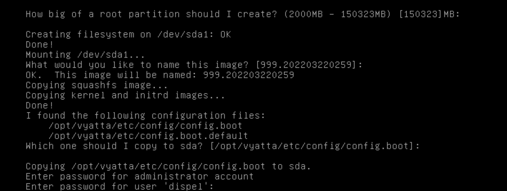
Enter and re-enter a new password for the user dispel.
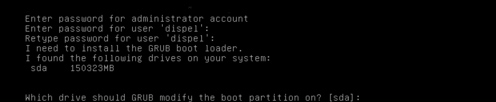
Press enter one final time to finish the installation.

Power off the machine, remove the provided ISO, and power it back on.
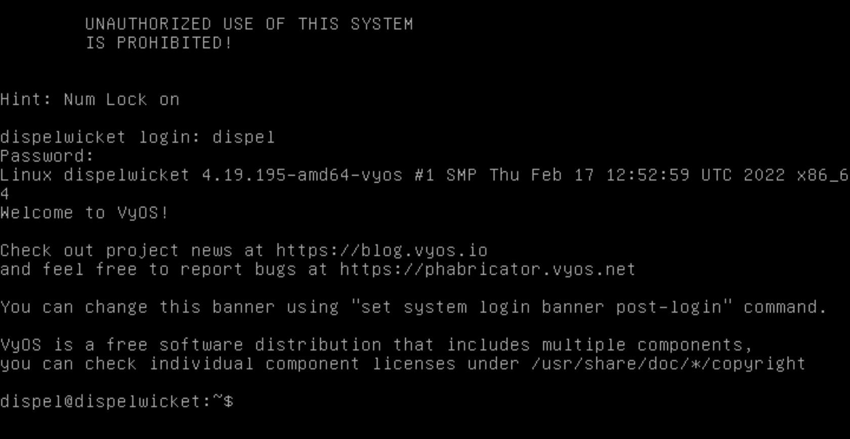
Log in with the user “dispel” and the new password set in step 9.
Type in the command
> ifconfig \| grep inet. Verify the output to make sure it matches the desired network configuration. If not, see the next section.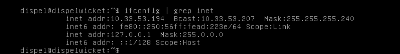
2.5.2 Configuring IP Addresses
Login to the device with the user “dispel”.
Type in the command
> configure.
Type in the command
> del interfaces ethernet eth0, or whichever interface you are currently modifying.
Type in the command
> set interfaces ethernet eth0 addressfollowed by the desired IP address in CIDR notation, modifying for the desired interface as appropriate.
Type in the command
> commit.
Type in the command
> save.
Type in the command
> exit.
2.5.3 Configuring Network
The following instructions are to modify a Dispel wicket device to forward traffic to a different routing device. This may be desirable for some network setups.
Type in the command
> configureto the Dispel wicket device after logging in.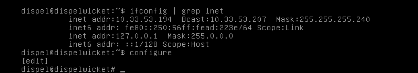
Type in the command
> set protocols static route 0.0.0/0 next-hopfollowed by the IP address of the router you wish to forward to.
Type in the command
> commit.
Type in the command
> save.
Type in the command
> exit.On the designated router or firewall, ensure UDP is allowed from the Dispel device on the provided port. For the NCCoE deployment, port 1194 was utilized. A target destination for the traffic will be provided by Dispel.
Modify the IP addresses of the south-side network interface to properly align with your network. See the “Configuring IP Addresses” section above.
2.5.4 Adding a Device
On the workstation in question, ensure that ping and RDP are accessible, including allowing such connections through a local firewall.
Authenticate to the Dispel webpage with the provided credentials.
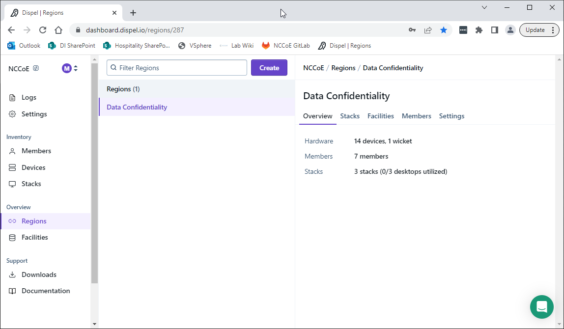
Click on the Devices page on the sidebar and click Create.
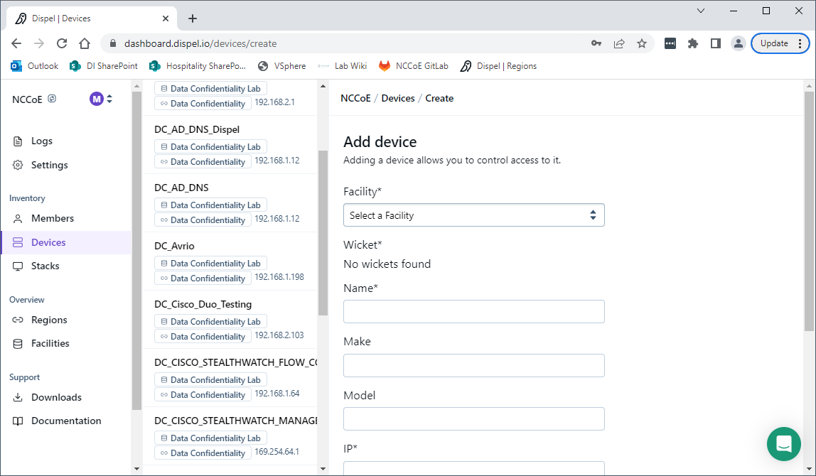
Under the Add Device window, fill out all fields, including Facility, Wicket, Name, Make, Model, IP, and Protocol.
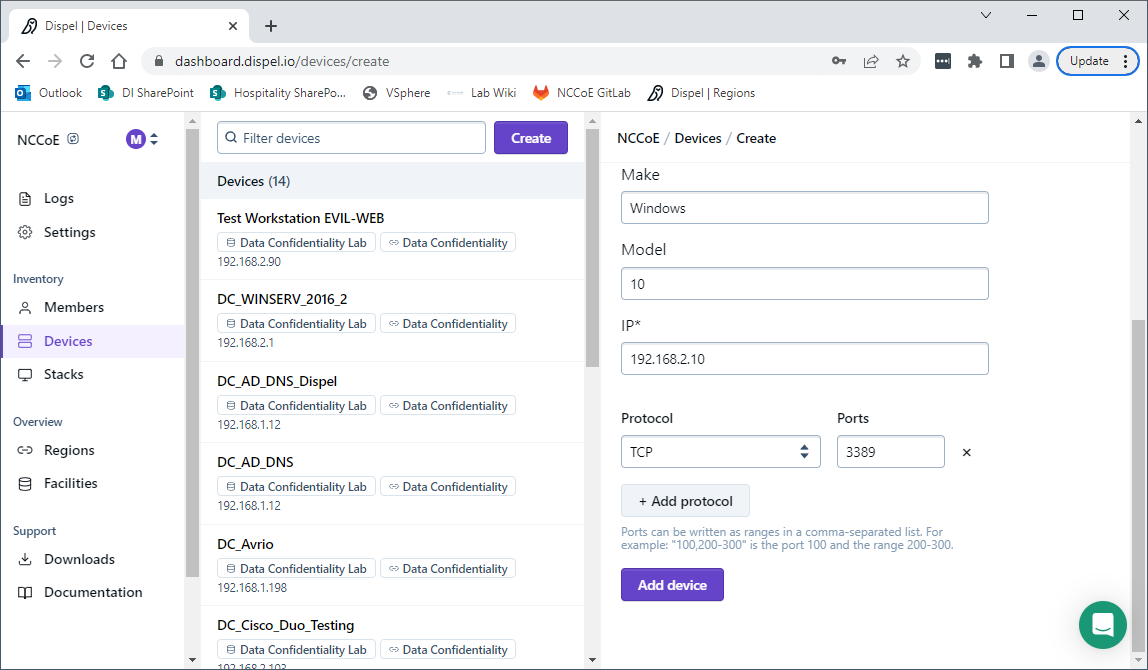
Click Add Device.
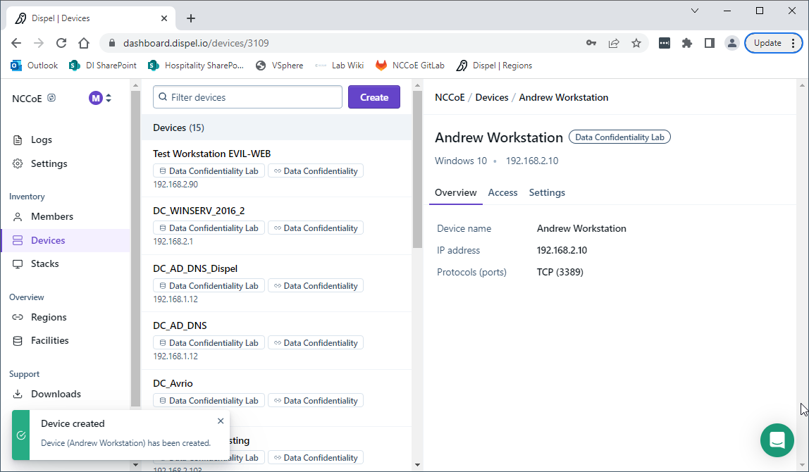
Under Access for that device, search for the user(s) that will have access to that device. Verify they have the correct access settings.
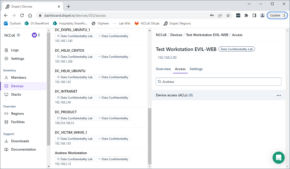
If a user is not already a member of the region, click on Members in the sidebar and click Invite. Fill out relevant information for this individual and click Invite this Member.
2.6 Integration: FireEye Helix and Cisco Stealthwatch
In the following section, Cisco Stealthwatch will be configured to forward logs to an on-premise Helix Communications Broker. Cisco Stealthwatch, as a network monitoring solution, can provide logs relevant to malicious network activity, potential data egress, as well as contextual information which can aid in the early detection of confidentiality events and the assessment of damage after an attack on confidentiality has occurred. An integration with the logging capability is useful for contextualizing information provided by other tools, generating alerts, and providing historical archives for reporting and compliance purposes.
2.6.1 Configure the Helix Communications Broker
On the CentOS system with the Helix Communications Broker installed, run the following commands:
> cd /opt/tap-nxlog

> sudo ./setup.sh
Select Add Routes and press Enter.
Select syslog.
Select udp.
Select the IP address of the network interface which should receive logs.
Enter 514 for the port.
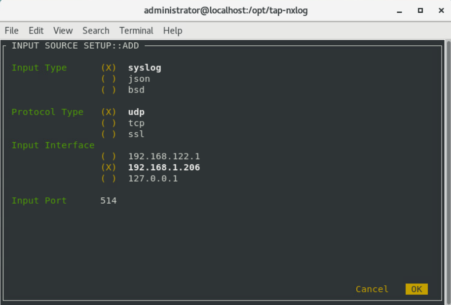
Select OK and press Enter.
Select OK and press Enter.
2.6.2 Configure Stealthwatch to Forward Events
Log on to the Stealthwatch Management Console web interface.
Navigate to Configure > Response Management.
Click the Actions tab.
Click the three dots next to Send to Syslog and click Edit.
Set the action to Enabled.
Enter the address of the Helix Communications Broker.
Enter the port which you selected earlier.
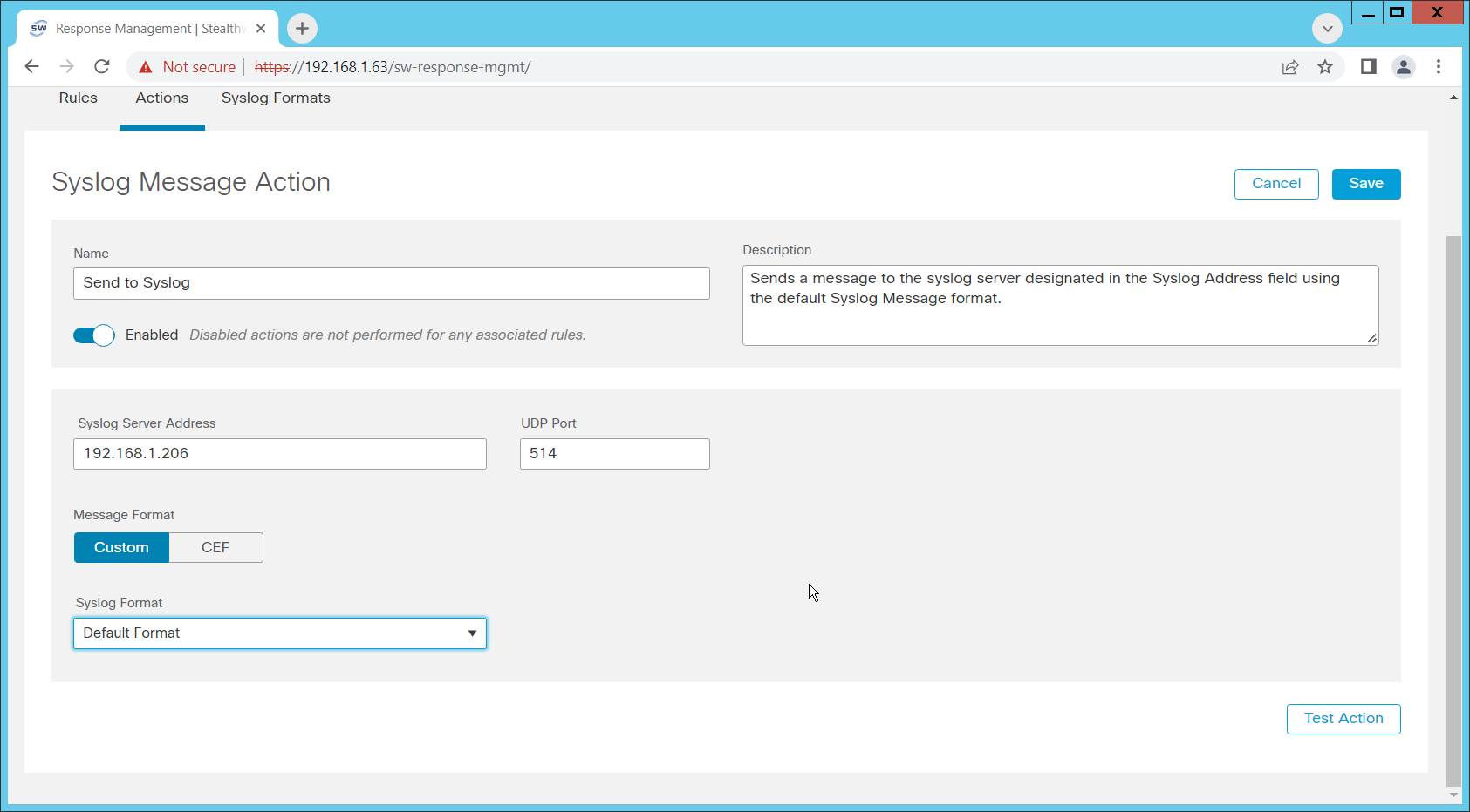
Click Save.
Click the Rules tab.
On the Actions tab, you can use some of the existing rules or create your own.
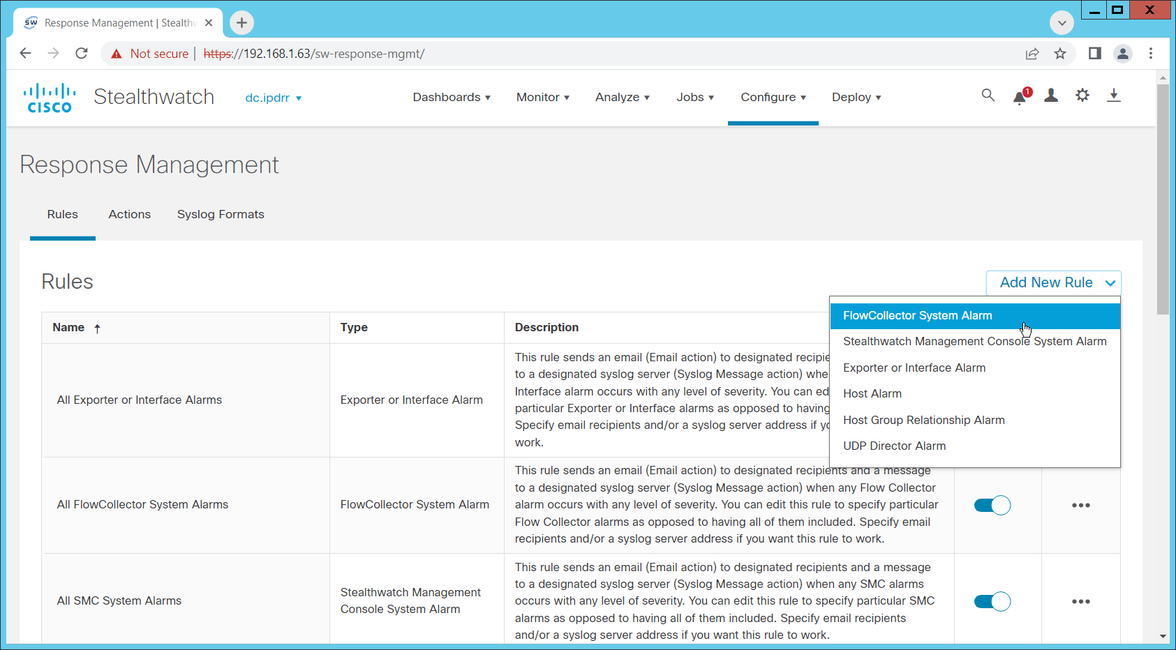
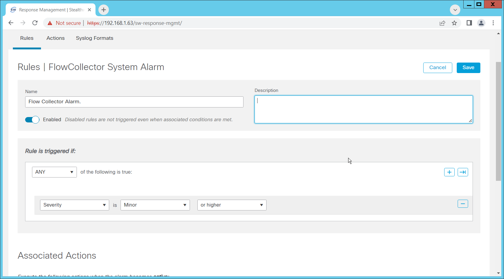
To create your own, click Add New Rule. For the purposes of this example, we select FlowCollector System Alarm.
Enter a name for the rule.
Ensure the rule is Enabled.
Click the plus sign under “Rule is triggered if”. You can select conditions for the rule to trigger, based on severity, processing time, and type.
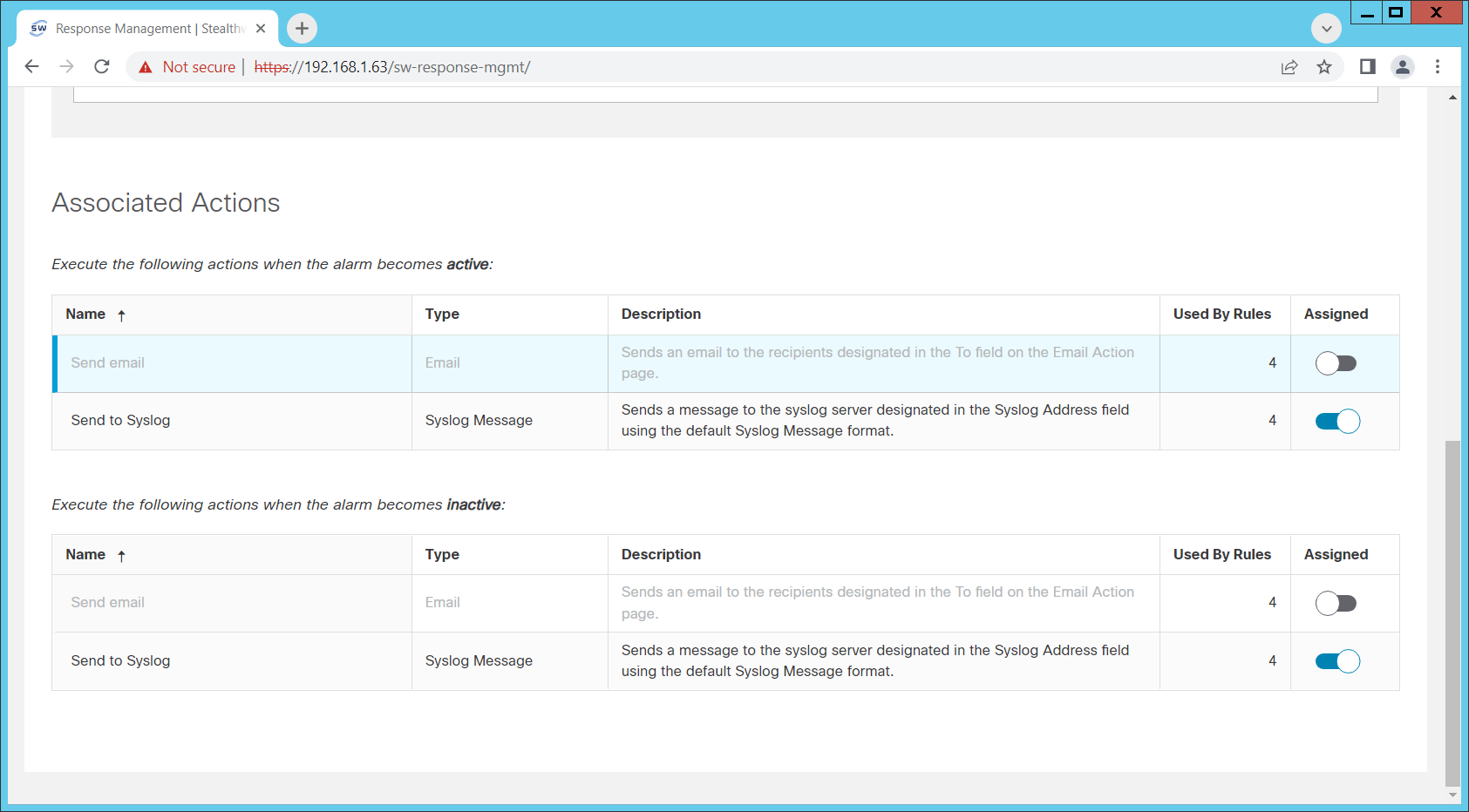
Enable Send to Syslog in the Associated Actions section. You can enable syslog messages for when the alarm becomes active and inactive.
You can also configure email alerts through this interface to improve the response time for incidents (this is a separate Action which needs to be edited on the Actions tab).
Click Save.
2.7 Integration: FireEye Helix and PKWARE PKProtect
In the following section, PKWARE PKProtect, which has been configured to identify and encrypt sensitive data, will be configured to forward these events to FireEye Helix. In this build, PKProtect provides data management capability which allows organizations to track data across an enterprise. As it is also providing encryption for this data, it provides important insight into sensitive data which is vulnerable to attack, as well as the ability to review, post-breach, which data may have been compromised in an attack. An integration with the logging capability is useful for contextualizing information provided by other tools, generating alerts, and providing historical archives for reporting and compliance purposes. This section assumes the Helix Communications Broker has already been installed.
2.7.1 Configure the Helix Communications Broker
On the CentOS system with the Helix Communications Broker installed, run the following commands:
> cd /opt/tap-nxlog

> sudo ./setup.sh
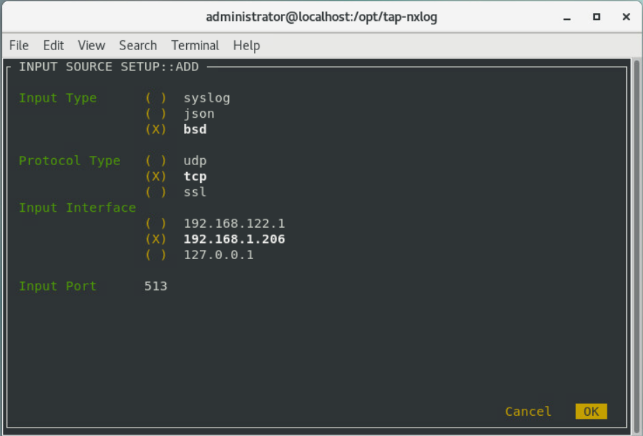
Select Add Routes and press Enter.
Select bsd.
Select tcp.
Select the IP address of the network interface which should receive logs.
Enter 513 for the port.
Select OK and press Enter.
Select OK and press Enter.
2.7.2 Configure PKWARE PKProtect to Forward Events
Navigate to the PKWARE PKProtect web portal.
Click the Basics link at the top of the page.
Scroll down to the Data Security Intelligence section.
Next to Dashboard Elasticsearch Target, click Internal.
Uncheck the box next to Use Internal Elasticsearch.
Uncheck the box next to Enable DSI in Dashboard.
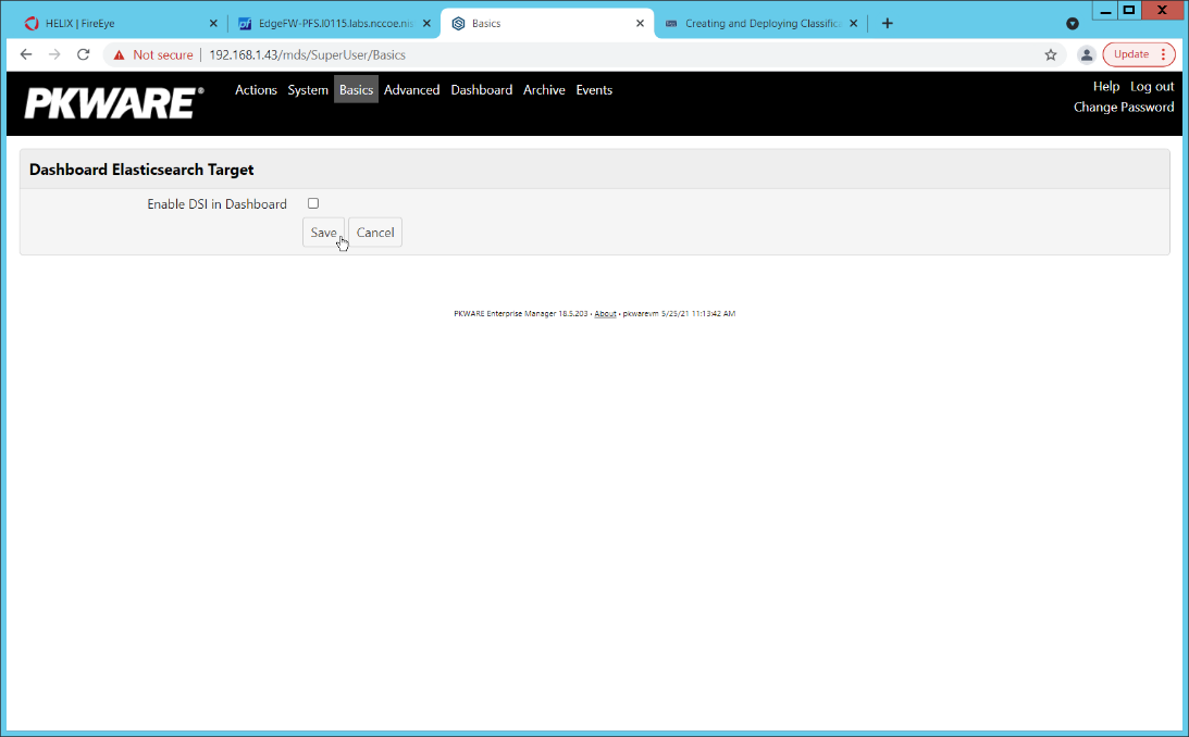
Click Save.
In the Data Security Intelligence section, click Internal next to Target.
Select Syslog TCP RFC-3164 for Target.
Enter the URL and port of the Helix Communications Broker that was just configured.
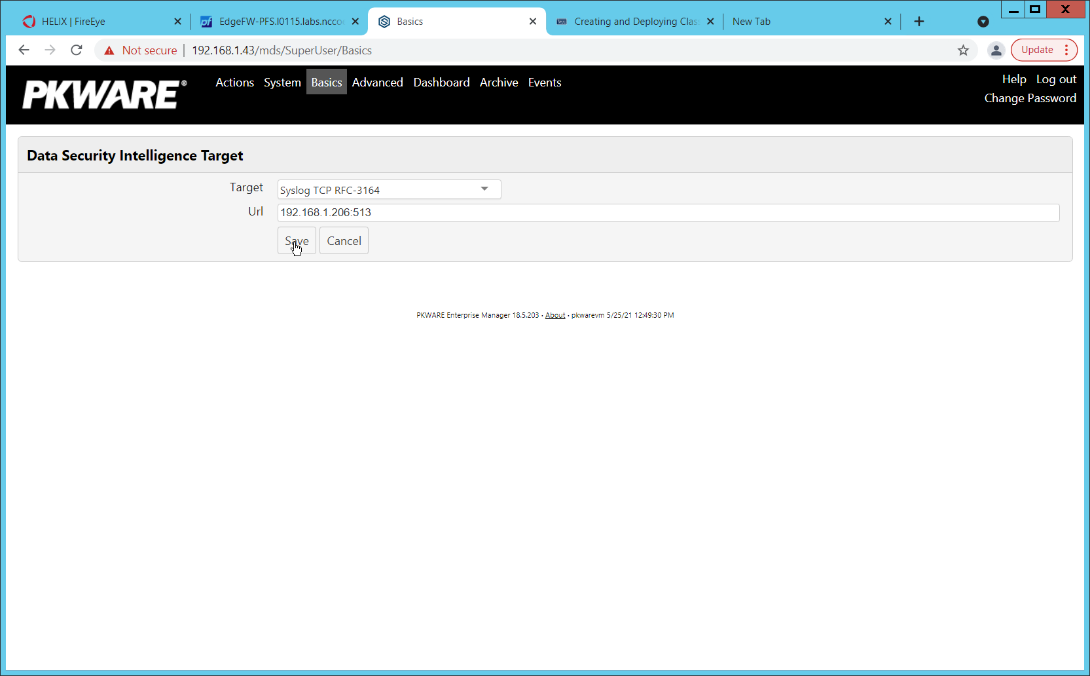
Click Save.
Verify that PKWARE logs now show up in Helix.
2.8 Integration: FireEye Helix and Dispel
In this integration, we configure the collection of logs from Dispel, our network protection solution. Because Dispel controls access from users to enterprise systems it is important to have an overview of its actions through log collection and reporting. This was a bespoke integration performed by Dispel. Organizations should ensure that this integration is performed, and discussed with their SIEM and Virtual Desktop Interface (VDI) vendors.
This integration has two primary components. The first, configuring the route, is done locally on the Dispel wicket. This can be done using the following commands. Ensure that you replace the <subnet> and the <gateway> such that the Dispel wicket can accurately route to the Helix Communications Broker.
> config

> set protocols static route <subnet> next-hop <gateway>

> commit && save && exit
The second component is configured server-side and involves informing the Dispel wicket via config file the actual port and location of the Helix Communications Broker. Instructions are not included for this, as in this integration, it was necessary to perform this integration remotely via the Dispel team.
2.9 Integration: Dispel and Cisco DUO
In this build, Dispel acts as an intermediary between the user and the enterprise systems, by providing temporary remote desktops with access to the enterprise systems. In this integration, we primarily installed Cisco Duo on the enterprise systems, to require multifactor authentication over RDP between Dispel’s temporary remote desktops and the enterprise systems.
In this particular integration, no extra work was required other than installing Cisco Duo (see Section 2.3) on systems to control remote desktop access between Dispel machines and the other machines. However, it is important for organizations to check that this integration works and is present, to ensure that multifactor authentication is being applied to users who are logging in remotely.