NIST SPECIAL PUBLICATION 1800-28C
Data Confidentiality:
Identifying and Protecting Assets Against Data Breaches
Volume C:
How-to Guides
William Fisher
February 2024
FINAL
This publication is available free of charge from https://doi.org/10.6028/NIST.SP.1800-28
The first draft of this publication is available free of charge from: https://www.nccoe.nist.gov/publications/practice-guide/data-confidentiality-identifying-and-protecting-assets-against-data

DISCLAIMER
Certain commercial entities, equipment, products, or materials may be identified by name or company logo or other insignia in order to acknowledge their participation in this collaboration or to describe an experimental procedure or concept adequately. Such identification is not intended to imply special status or relationship with NIST or recommendation or endorsement by NIST or NCCoE; neither is it intended to imply that the entities, equipment, products, or materials are necessarily the best available for the purpose.
While NIST and the NCCoE address goals of improving management of cybersecurity and privacy risk through outreach and application of standards and best practices, it is the stakeholder’s responsibility to fully perform a risk assessment to include the current threat, vulnerabilities, likelihood of a compromise, and the impact should the threat be realized before adopting cybersecurity measures such as this recommendation.
National Institute of Standards and Technology Special Publication 1800-28C, Natl. Inst. Stand. Technol. Spec. Publ. 1800-28C, 86 pages, (February 2024), CODEN: NSPUE2
FEEDBACK
As a private-public partnership, we are always seeking feedback on our practice guides. We are particularly interested in seeing how businesses apply NCCoE reference designs in the real world. If you have implemented the reference design, or have questions about applying it in your environment, please email us at ds-nccoe@nist.gov.
All comments are subject to release under the Freedom of Information Act.
NATIONAL CYBERSECURITY CENTER OF EXCELLENCE
The National Cybersecurity Center of Excellence (NCCoE), a part of the National Institute of Standards and Technology (NIST), is a collaborative hub where industry organizations, government agencies, and academic institutions work together to address businesses’ most pressing cybersecurity issues. This public-private partnership enables the creation of practical cybersecurity solutions for specific industries, as well as for broad, cross-sector technology challenges. Through consortia under Cooperative Research and Development Agreements (CRADAs), including technology partners—from Fortune 50 market leaders to smaller companies specializing in information technology security—the NCCoE applies standards and best practices to develop modular, adaptable example cybersecurity solutions using commercially available technology. The NCCoE documents these example solutions in the NIST Special Publication 1800 series, which maps capabilities to the NIST Cybersecurity Framework and details the steps needed for another entity to re-create the example solution. The NCCoE was established in 2012 by NIST in partnership with the State of Maryland and Montgomery County, Maryland.
NIST CYBERSECURITY PRACTICE GUIDES
NIST Cybersecurity Practice Guides (Special Publication 1800 series) target specific cybersecurity challenges in the public and private sectors. They are practical, user-friendly guides that facilitate the adoption of standards-based approaches to cybersecurity. They show members of the information security community how to implement example solutions that help them align with relevant standards and best practices, and provide users with the materials lists, configuration files, and other information they need to implement a similar approach.
The documents in this series describe example implementations of cybersecurity practices that businesses and other organizations may voluntarily adopt. These documents do not describe regulations or mandatory practices, nor do they carry statutory authority.
ABSTRACT
Attacks that target data are of concern to companies and organizations across many industries. Data breaches represent a threat that can have monetary, reputational, and legal impacts. This guide seeks to provide guidance around the threat of data breaches, exemplifying standards and technologies that are useful for a variety of organizations defending against this threat. Specifically, this guide identifies risks associated with the loss of data confidentiality, and mitigations to protect against those risks.
KEYWORDS
asset management; cybersecurity framework; data breach; data confidentiality; data protection; identify; malicious actor; malware; protect; ransomware
ACKNOWLEDGMENTS
We are grateful to the following individuals for their generous contributions of expertise and time.
Name |
Organization |
|---|---|
Jason Winder |
Avrio Software (now known as Aerstone) |
Trey Doré |
Cisco |
Matthew Hyatt |
Cisco |
Randy Martin |
Cisco |
Peter Romness |
Cisco |
Bryan Rosensteel |
Cisco |
Micah Wilson |
Cisco |
Ben Burke |
Dispel |
Fred Chang |
Dispel |
Matt Fulk |
Dispel |
Ian Schmertzler |
Dispel |
Kenneth Durbin |
FireEye |
Tom Los |
FireEye |
J.R. Wikes |
FireEye |
Jennifer Cawthra |
NIST |
Joe Faxlanger |
PKWARE |
Victor Ortiz |
PKWARE |
Jim Wyne |
PKWARE |
Steve Petruzzo |
Qcor |
Billy Stewart |
Qcor |
Norman Field |
StrongKey |
Patrick Leung |
StrongKey |
Arshad Noor |
StrongKey |
Dylan Buel |
Symantec, a division of Broadcom |
Sunjeet Randhawa |
Symantec, a division of Broadcom |
Paul Swinton |
Symantec, a division of Broadcom |
Lauren Acierto |
The MITRE Corporation |
Spike Dog |
The MITRE Corporation |
Sallie Edwards |
The MITRE Corporation |
Brian Johnson |
The MITRE Corporation |
Lauren Lusty |
The MITRE Corporation |
Karri Meldorf |
The MITRE Corporation |
Julie Snyder |
The MITRE Corporation |
Lauren Swan |
The MITRE Corporation |
Anne Townsend |
The MITRE Corporation |
Jessica Walton |
The MITRE Corporation |
The Technology Partners/Collaborators who participated in this build submitted their capabilities in response to a notice in the Federal Register. Respondents with relevant capabilities or product components were invited to sign a Cooperative Research and Development Agreement (CRADA) with NIST, allowing them to participate in a consortium to build this example solution. We worked with:
Technology Partner/Collaborator |
Build Involvement |
|---|---|
Avrio |
Avrio SIFT |
Cisco Systems |
DUO |
Dispel |
Dispel |
FireEye |
FireEye Helix |
Qcor |
Qcor ForceField |
PKWARE |
PKWARE PKProtect |
StrongKey |
StrongKey Tellaro |
Symantec, a Division of Broadcom |
Symantec Web Isolation |
DOCUMENT CONVENTIONS
The terms “shall” and “shall not” indicate requirements to be followed strictly to conform to the publication and from which no deviation is permitted. The terms “should” and “should not” indicate that among several possibilities, one is recommended as particularly suitable without mentioning or excluding others, or that a certain course of action is preferred but not necessarily required, or that (in the negative form) a certain possibility or course of action is discouraged but not prohibited. The terms “may” and “need not” indicate a course of action permissible within the limits of the publication. The terms “can” and “cannot” indicate a possibility and capability, whether material, physical, or causal.
PATENT DISCLOSURE NOTICE
NOTICE: The Information Technology Laboratory (ITL) has requested that holders of patent claims whose use may be required for compliance with the guidance or requirements of this publication disclose such patent claims to ITL. However, holders of patents are not obligated to respond to ITL calls for patents and ITL has not undertaken a patent search in order to identify which, if any, patents may apply to this publication.
As of the date of publication and following call(s) for the identification of patent claims whose use may be required for compliance with the guidance or requirements of this publication, no such patent claims have been identified to ITL.
No representation is made or implied by ITL that licenses are not required to avoid patent infringement in the use of this publication.
1 Introduction
The following volumes of this guide show information technology (IT) professionals and security engineers how we implemented this example solution. We cover all of the products employed in this reference design. We do not re-create the product manufacturers’ documentation, which is presumed to be widely available. Rather, these volumes show how we incorporated the products together in our lab environment.
Note: These are not comprehensive tutorials. There are many possible service and security configurations for these products that are out of scope for this reference design.
1.1 How to Use this Guide
This National Institute of Standards and Technology (NIST) Cybersecurity Practice Guide demonstrates a standards-based reference design and provides users with the information they need to replicate the ability to identify threats to and protect from a loss of data confidentiality. This reference design is modular and can be deployed in whole or in part.
This guide contains three volumes:
NIST SP 1800-28A: Executive Summary
NIST SP 1800-28B: Approach, Architecture, and Security Characteristics – what we built and why
NIST SP 1800-28C: How-To Guides – instructions for building the example solution (you are here)
Depending on your role in your organization, you might use this guide in different ways:
Business decision makers, including chief security and technology officers, will be interested in the Executive Summary, NIST SP 1800-28A, which describes the following topics:
challenges that enterprises face in identifying vulnerable assets and protecting them from data breaches
example solution built at the NCCoE
benefits of adopting the example solution
Technology or security program managers who are concerned with how to identify, understand, assess, and mitigate risk will be interested in NIST SP 1800-28B, which describes what we did and why. The following sections will be of particular interest:
Section 3.5, Risk Assessment, describes the risk analysis we performed.
Appendix D, Security Control Map, maps the security characteristics of this example solution to cybersecurity standards and best practices.
You might share the Executive Summary, NIST SP 1800-28A, with your leadership team members to help them understand the importance of adopting a standards-based solution to identify threats to and protect from a loss of data confidentiality
IT professionals who want to implement an approach like this will find this whole practice guide useful. You can use this How-To portion of the guide, NIST SP 1800-28C, to replicate all or parts of the build created in our lab. This How-To portion of the guide provides specific product installation, configuration, and integration instructions for implementing the example solution. We do not recreate the product manufacturers’ documentation, which is generally widely available. Rather, we show how we incorporated the products together in our environment to create an example solution.
This guide assumes that IT professionals have experience implementing security products within the enterprise. While we have used a suite of commercial products to address this challenge, this guide does not endorse these particular products. Your organization can adopt this solution or one that adheres to these guidelines in whole, or you can use this guide as a starting point for tailoring and implementing parts of a solution to identify threats to and protect from a loss of data confidentiality. Your organization’s security experts should identify the products that will best integrate with your existing tools and IT system infrastructure. We hope that you will seek products that are congruent with applicable standards and best practices. Section 3.6 Technologies, lists the products that we used and maps them to the cybersecurity controls provided by this reference solution.
A NIST Cybersecurity Practice Guide does not describe “the” solution but a possible solution. Comments, suggestions, and success stories will improve subsequent versions of this guide. Please contribute your thoughts to ds-nccoe@nist.gov .
1.2 Build Overview
The NCCoE built a hybrid virtual-physical laboratory environment to explore methods to effectively identify sensitive data and protect against a loss of data confidentiality in various Information Technology (IT) enterprise environments. This work also highlights standards and technologies that are useful for a variety of organizations defending against this threat. The servers in the virtual environment were built to the hardware specifications of their specific software components.
The NCCoE worked with members of the Data Confidentiality Community of Interest to develop a diverse (but non-comprehensive) set of security scenarios against which to test the reference implementation. These are detailed in Volume B, Section 5.2.
1.3 Typographic Conventions
The following table presents typographic conventions used in this volume.
Typeface/ Symbol |
Meaning |
Example |
|---|---|---|
Italics |
file names and path names; references to documents that are not hyperlinks; new terms; and placeholders |
For language use and style guidance, see the NCCoE Style Guide. |
Bold |
names of menus, options, command buttons, and fields |
Choose File > Edit. |
|
command-line input, onscreen computer output, sample code examples, and status codes |
|
Monospace (block)
|
multi-line input, on-screen computer output, sample code examples, status codes |
% mkdir -v nccoe_projects
mkdir: created directory 'nccoe_projects'
|
link to other parts of the document, a web URL, or an email address |
All publications from NIST’s NCCoE are available at https://www.nccoe.nist.gov. |
1.4 Logical Architecture Summary
The architecture described is built within the NCCoE lab environment. Organizations will need to consider how the technologies in this architecture will align technologies their existing infrastructure. In addition to network management resources, such as a border firewall, the architecture assumes the presence of user workstations, an active directory system, and databases. The diagram below shows the components of the architecture and how they interact with enterprise resources.
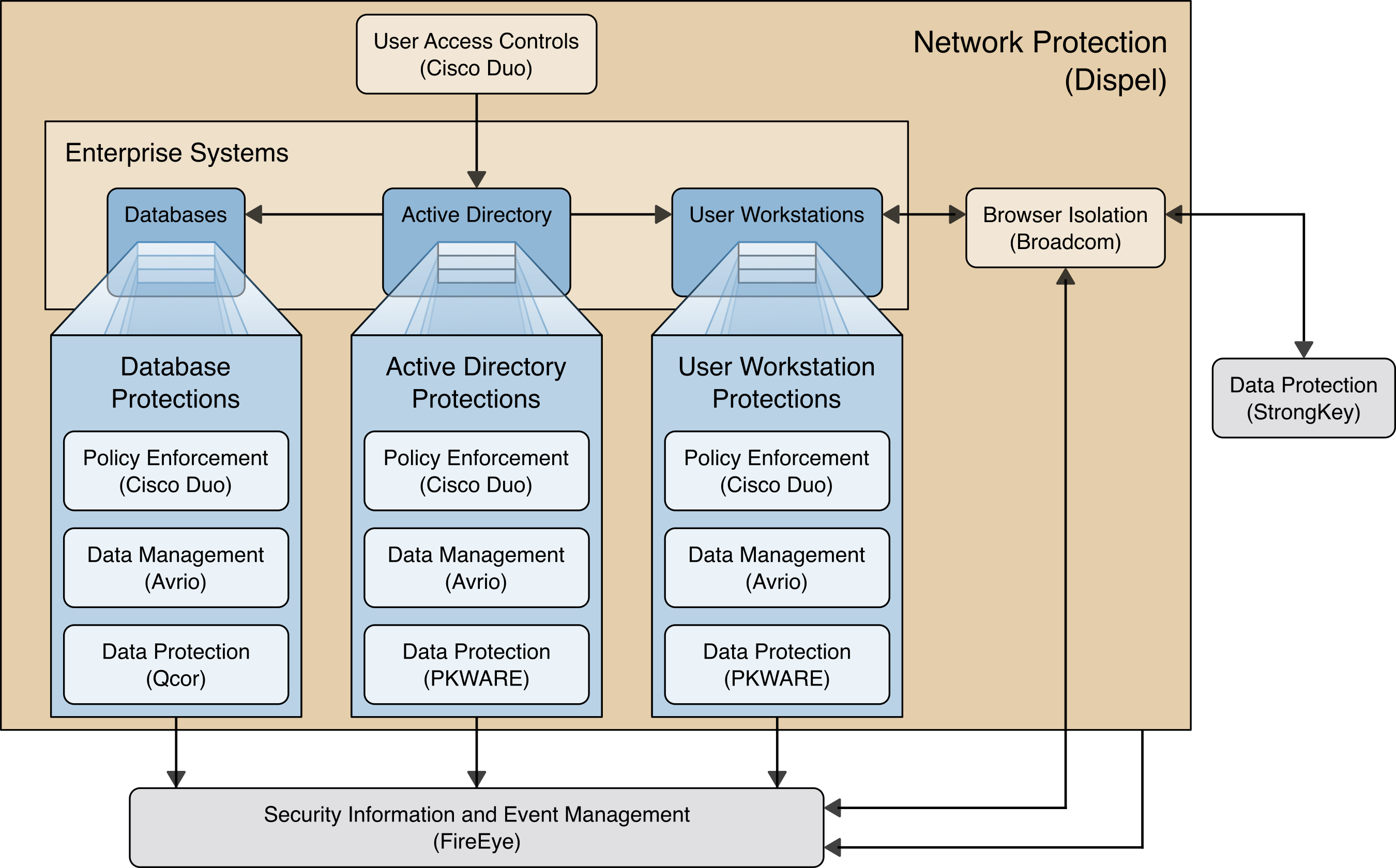
Data Management (Avrio) allows discovery and tracking of files throughout the enterprise.
Data Protection (GreenTec, StrongKey, PKWARE) involves encryption and protection against disclosure of sensitive files.
User Access Controls (Cisco Duo) allows organizations to enforce access control policies, ensuring that only authorized users have access to sensitive files.
Browser Isolation (Symantec SWG) protects endpoints in the organization from malicious web-based threats by utilizing multi-layered content inspection to block threats and remote isolation of content from high-risk and unknown sites.
Policy Enforcement (Cisco Duo) ensures that endpoints in the organization conform to specified security policies, which can include certificate verification, installed programs, and machine posture.
Security Information and Event Management (FireEye Helix) creates a baseline of a normal enterprise activity for comparison in the event of a data confidentiality event. This function includes the collection, aggregation, and analysis of logs throughout the enterprise, including logs from other security tools, to provide a better picture of the overall health of the enterprise before a breach should occur.
Network Protection (Dispel) ensures that hosts on the network only communicate in allowed ways, preventing side-channel attacks and attacks that rely on direct communication between hosts. Furthermore, it protects against potentially malicious hosts joining or observing traffic (encrypted or decrypted) traversing the network.
For a more detailed description of our architecture, see Volume B, Section 4.
2 Product Installation Guides
This section of the practice guide contains detailed instructions for installing and configuring all of the products used to build an instance of the example solution. This implementation guide is split into sections for each product and integrations between these products, aiming to present a modular architecture where individual capabilities and products can be swapped out or excluded depending on the needs of the organization. Organizations can choose to implement a partial architecture based on their own risk assessments and data protection requirements.
2.1 FireEye Helix
FireEye Helix is a security incident and event management system used for collecting and managing logs from various sources. In this build, Helix is primarily used to manage events and alerts generated by data collected from across the enterprise. This build implemented a cloud deployment of Helix, and as such, much of the documentation provided will be integrating a cloud deployment with various products and components of the enterprise.
In this setup, we detail the installation of a communications broker, which will be used to collect logs from the enterprise and forward them to the cloud deployment. This installation took place on a CentOS 7 Virtual Machine.
2.1.1 Installing the Communications Broker - CentOS 7
Acquire the Helix Communications Broker for CentOS 7.
Navigate to the folder containing the installer, and run
> sudo yum localinstall ./cbs-installer_1.4.2-9.x86_64.rpm
Log on to the Helix web console.
Navigate to Dashboards > Operational.
Click Download Certificate.
Click Download. This will download a “bootstrap.zip” file.
Copy the zip file to the Helix Communications Broker certificate directory.
> sudo cp bootstrap.zip /opt/tap-nxlog/cert
Navigate to the certificate directory.
> cd /opt/tap-nxlog/cert
Extract the zip file you just copied.
> sudo unzip ./bootstrap.zip
If prompted, select “Yes” to overwrite any previous certificate files.
Navigate to one folder above.
> sudo cd ..
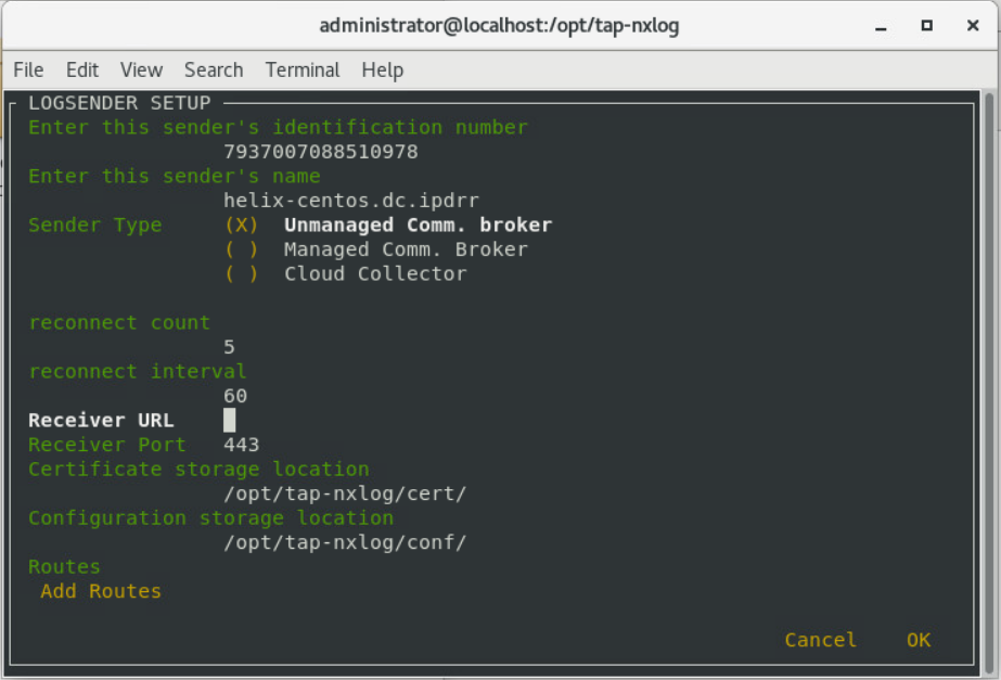
Run the setup script.
> sudo ./setup.sh
Enter the name of the CentOS machine.
Enter the receiver URL provided in the Helix welcome email.
Select Add Routes and press Enter.
Select syslog.
Select tcp.
Select the Internet Protocol (IP) address of the machine where logs should be sent.
Enter 512 for the port number where logs should be sent.
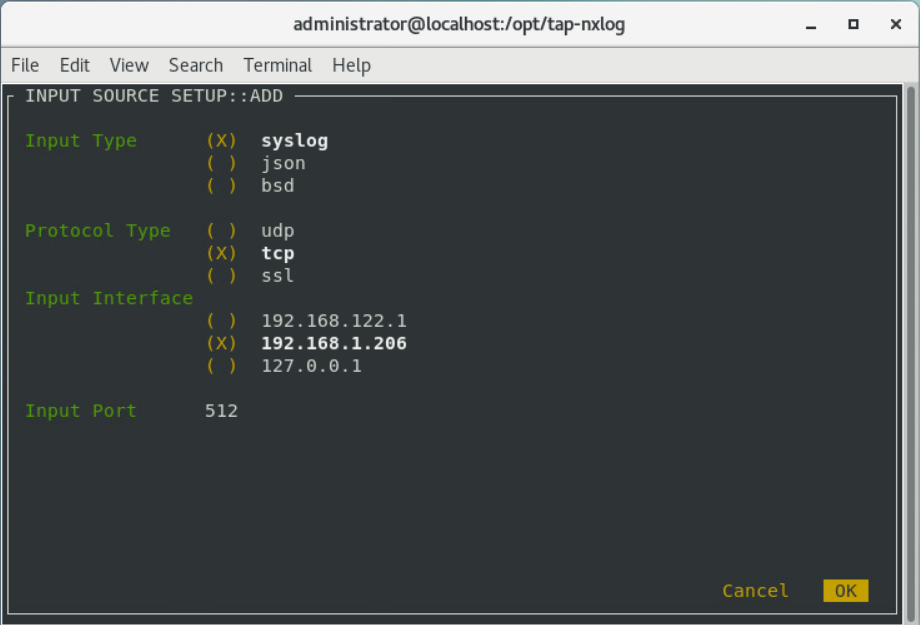
Select OK and press Enter.
Review the configuration, then select OK and press Enter.
2.1.2 Forwarding Event Logs from Windows 2012 R2
Acquire nxlog-ce-2.10.2150.msi from http://nxlog.org/products/nxlog-community-edition/download.
Run nxlog-ce-2.10.2150.msi.
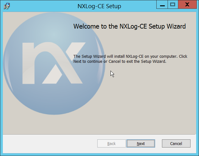
Click Next.
Check the box next to I accept the terms in the License Agreement.
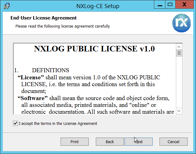
Click Next.
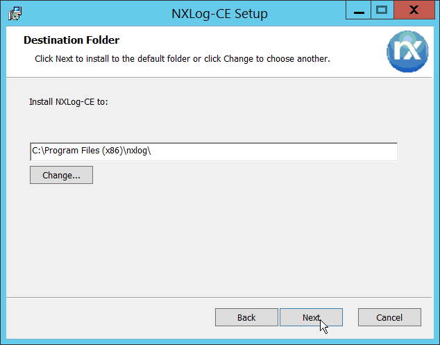
Click Next.
Click Install.
Click Finish.
Navigate to C:\Program Files (x86)\nxlog\conf and open nxlog.conf.
Copy the nxlog.conf file provided below.
Panic Soft
#NoFreeOnExit TRUE

define ROOT C:\Program Files (x86)\nxlog
define CERTDIR %ROOT%\cert
define CONFDIR %ROOT%\conf
define LOGDIR %ROOT%\data
define LOGFILE %LOGDIR%\nxlog.log
LogFile %LOGFILE%

Moduledir %ROOT%\modules
CacheDir %ROOT%\data
Pidfile %ROOT%\data\nxlog.pid
SpoolDir %ROOT%\data

<Extension \_syslog>
    Module xm_syslog
</Extension>

<Input in>
    Module im_msvistalog
# For windows 2003 and earlier use the following:
# Module im_mseventlog
</Input>

<Output out>
    Module om_tcp
    Host 192.168.1.206
    Port 512
    Exec to_syslog_snare();
</Output>

<Route 1>
    Path in => out
</Route>
Restart the nxlog service.
You can verify that this connection is working by checking the logs in data\nxlog.log, and by noting an increase in events on the Helix Dashboard.
2.2 Symantec Cloud Secure Web Gateway
This installation and configuration guide for Symantec SWG uses a cloud instance of Web Isolation. In this guide, Web Isolation is used to isolate threats to the user through the browser. It does this through the use of a web proxy, which captures traffic and assigns a threat level to it, and based on administrative policy decides whether to serve the page to the user. In doing so, threats from the web can be mitigated through shared intelligence and isolated execution of the page before it reaches the user’s desktop.
2.2.1 Configure Web Security Service (WSS)
Login to the Symantec portal by navigating to https://portal.threatpulse.com/.
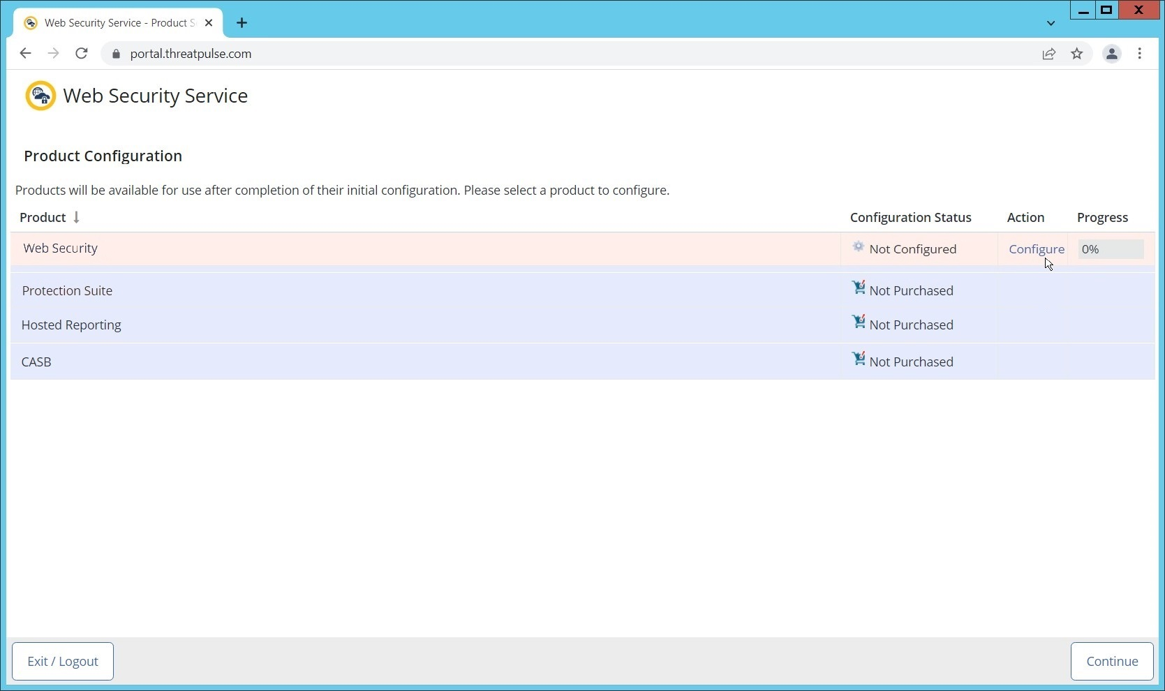
Click Configure next to Protection Suite.
Select WSS Portal.
Select Monitor.
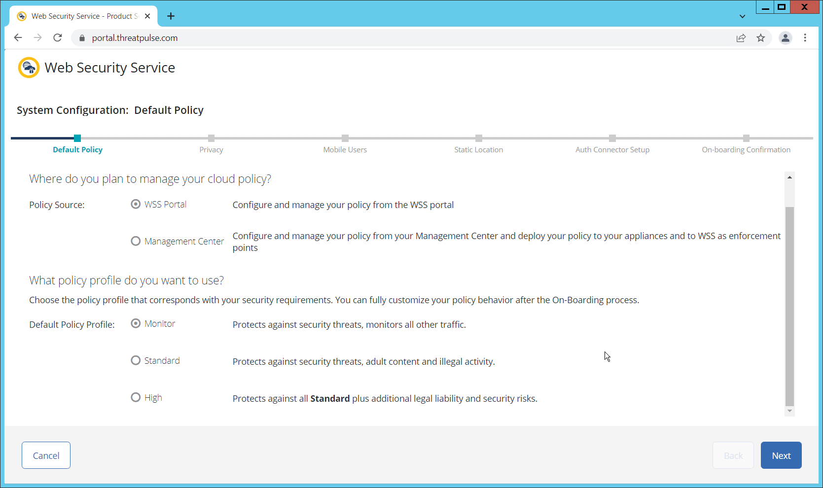
Click Next.
Select Suppress User/Group, Device Info, Client IP, Geolocation. (Note: If you are planning to use this tool for network monitoring of organizational users, a less strict privacy policy may be preferable; however, for this build, we are using Web Isolation primarily for external threats.)
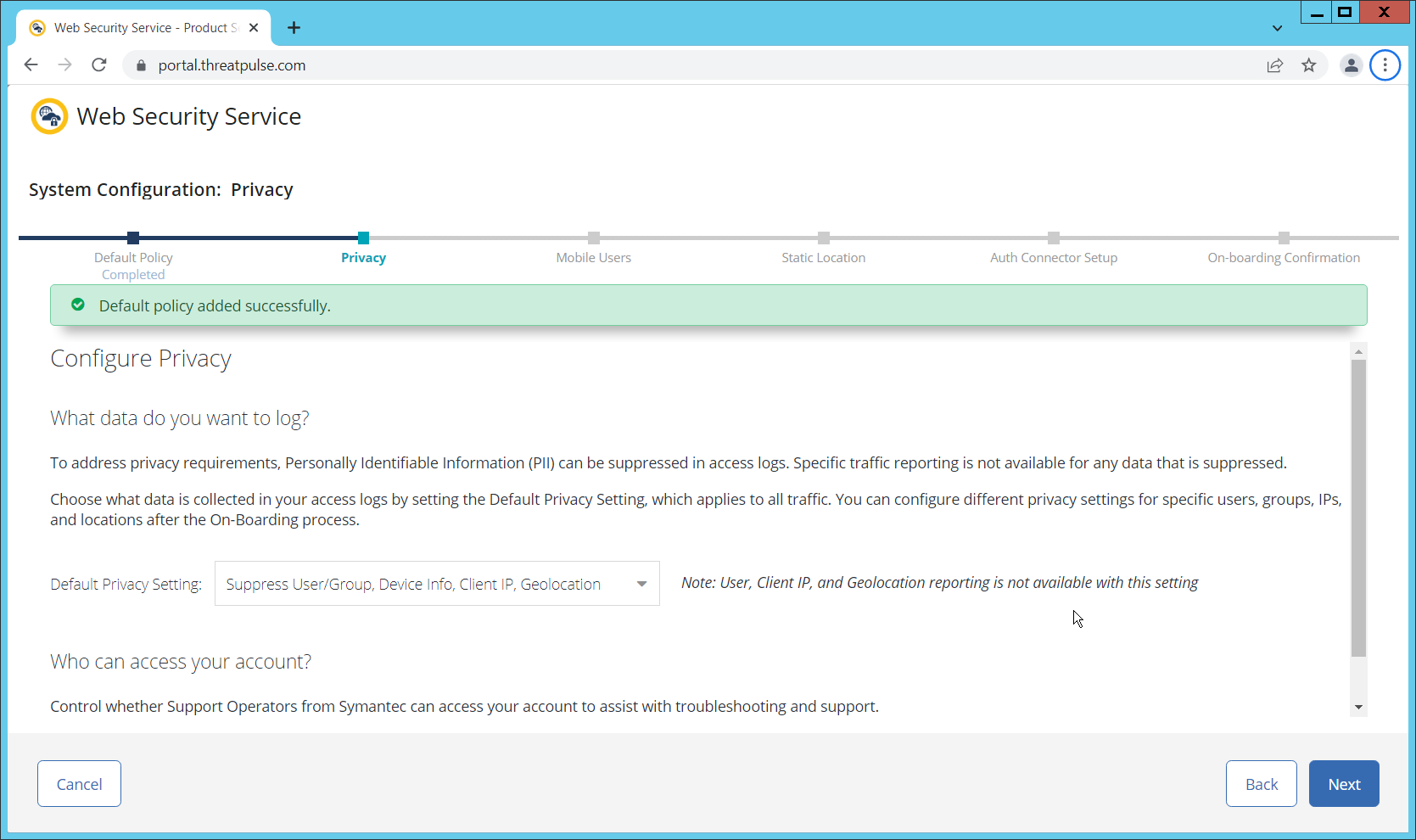
Click Next.
Indicate whether you have mobile users.
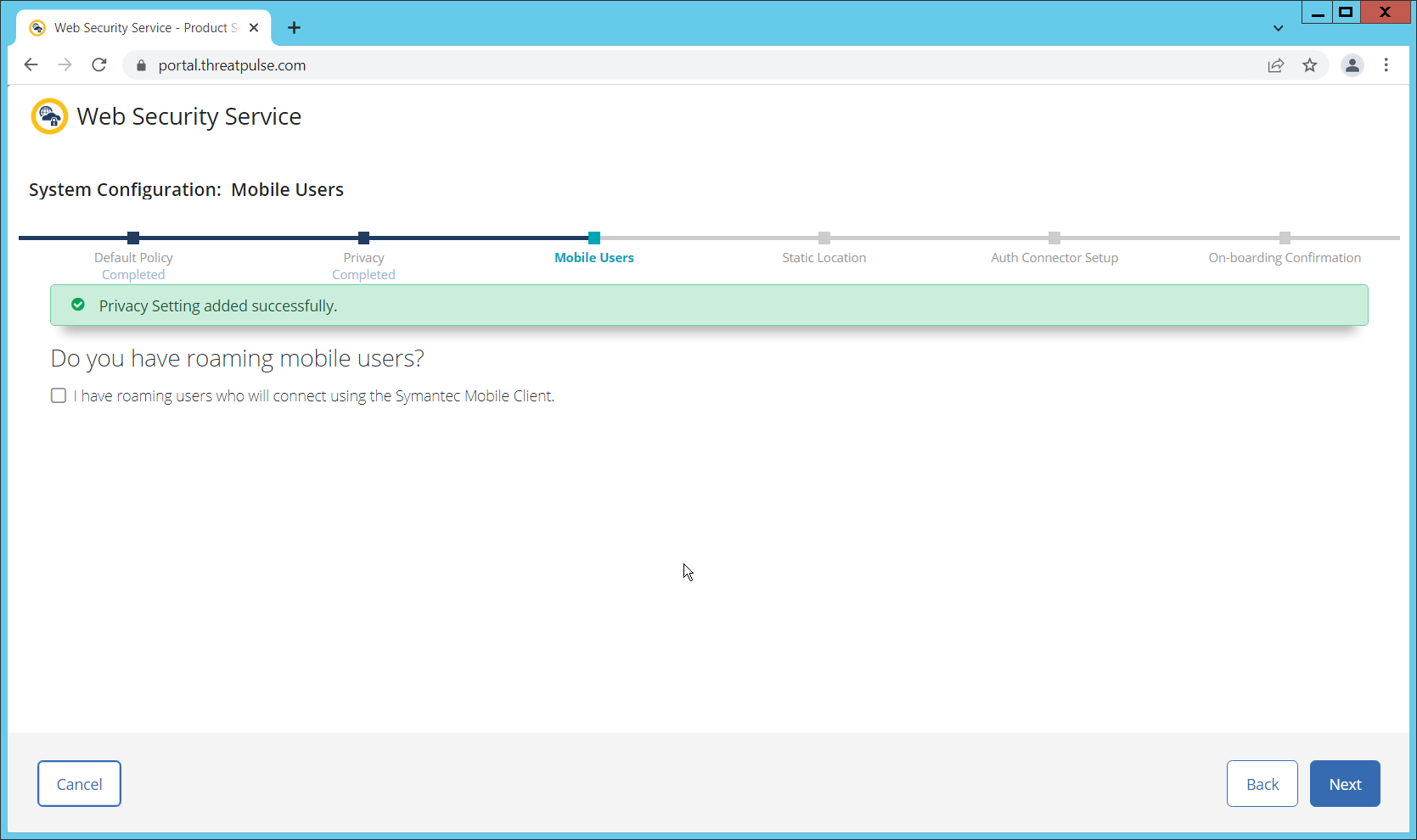
Click Next. Indicate whether your users connect from a static location.
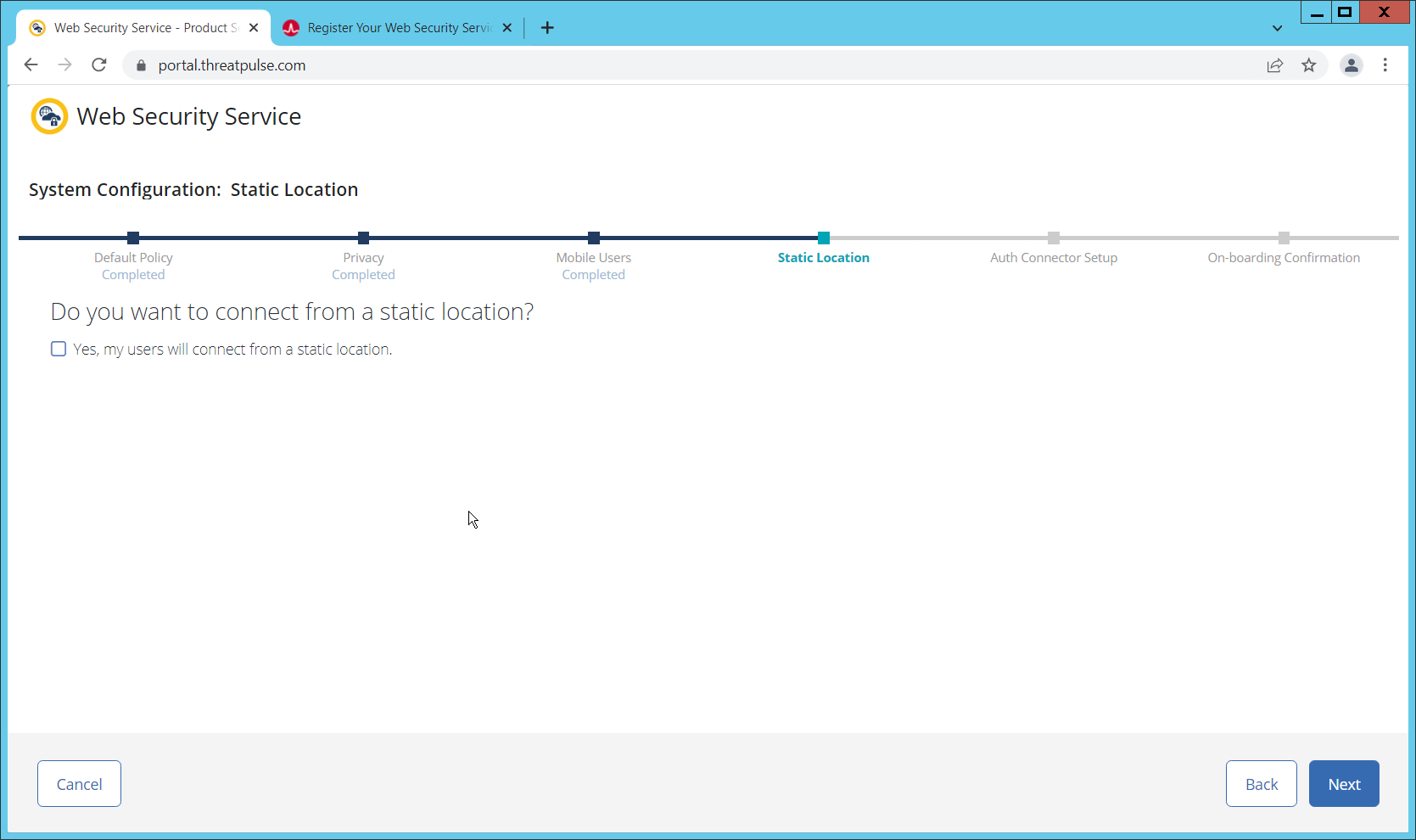
Click Next. Indicate whether you want to configure an Auth Connector.
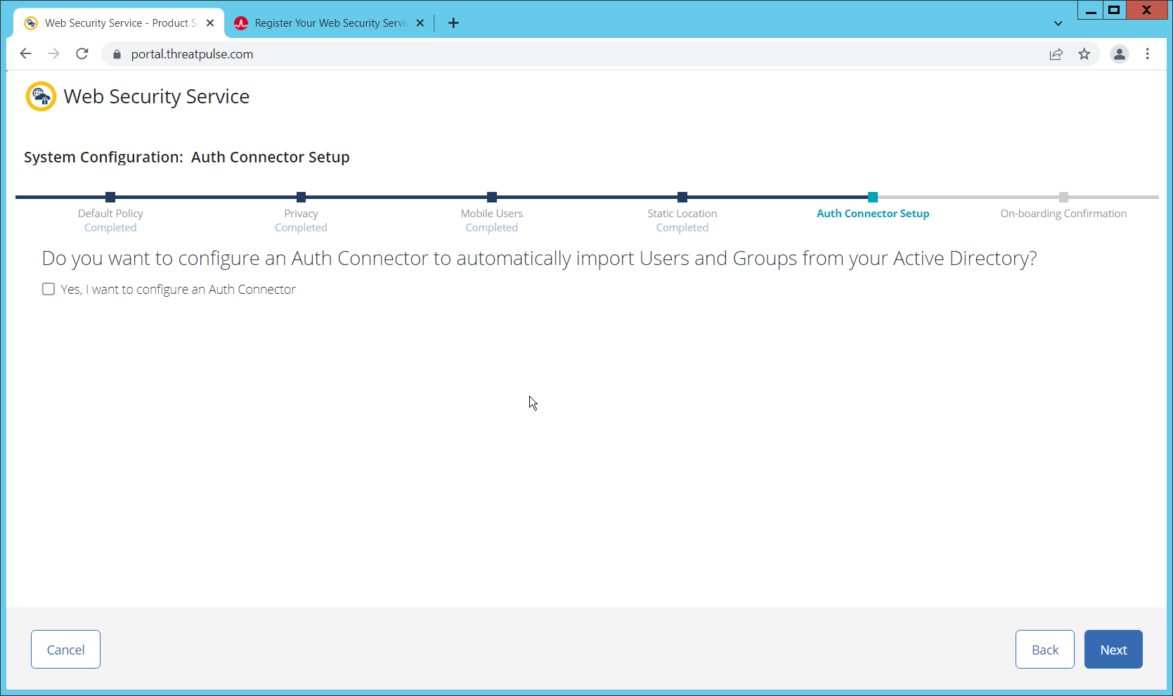
Click Next.
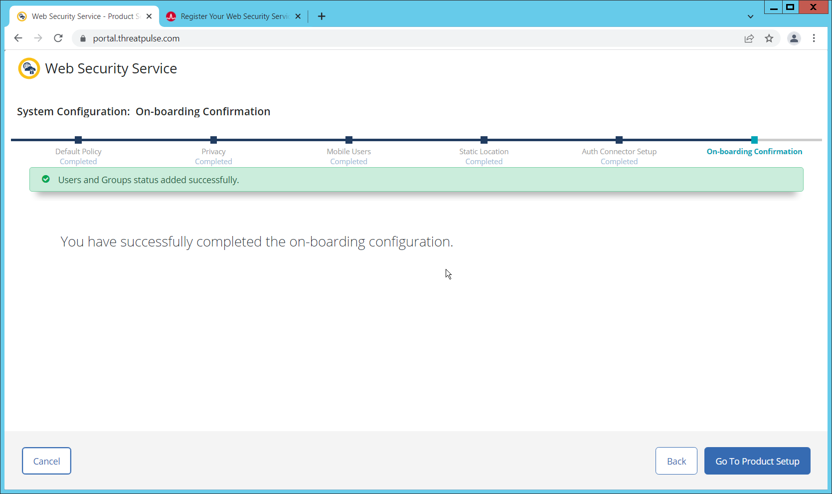
Click Go To Product Setup.
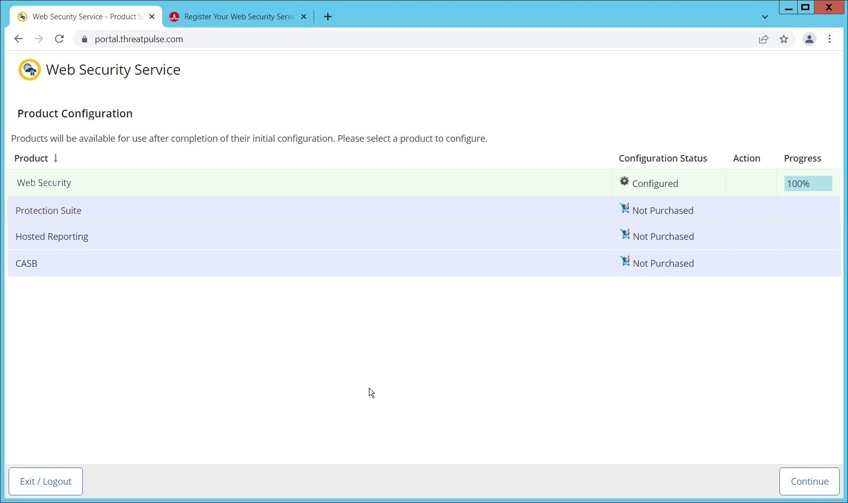
Click Continue.
2.2.2 Install Proxy Certificates and enabling TLS/SSL Interception
Click the Policy tab.
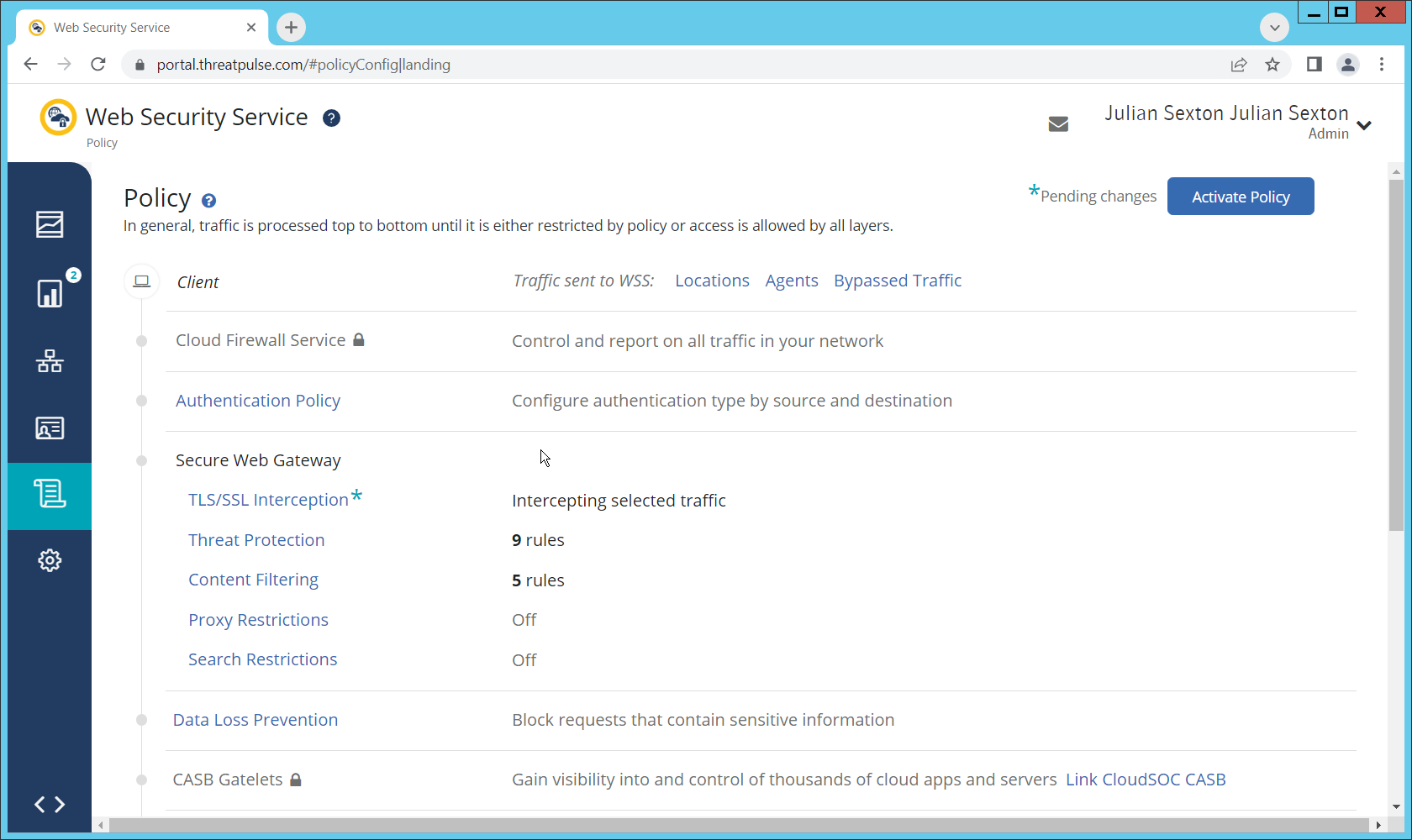
Click TLS/SSL Interception.
Enable TLS/SSL interception by clicking the toggle.
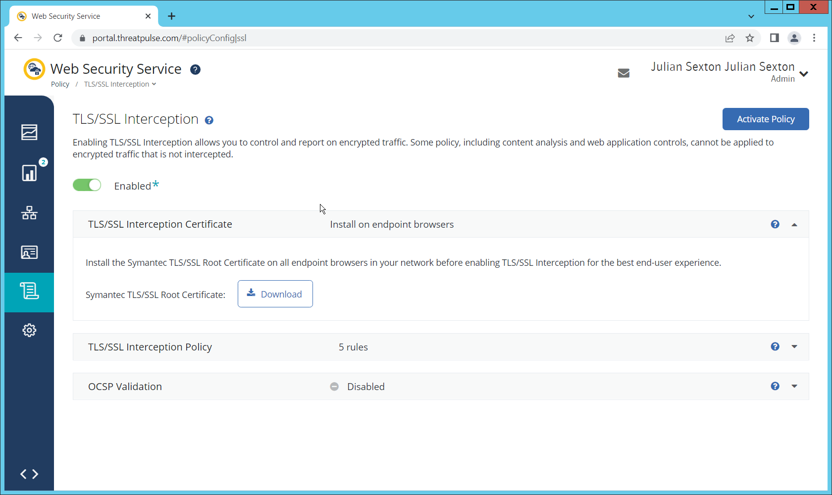
Download the certificate here. You can either install this individually in the Trusted Root Certification Authorities store on individual machines or follow the below steps to distribute the certificate via Group Policy.
Open the Group Policy Management Console.
Right click the Domain and select Create a GPO in this domain, and Link it here….
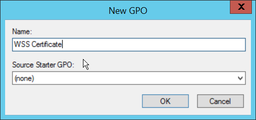
Enter a name and click OK.
Right click the newly created GPO and click Edit….
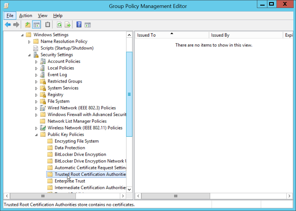
Navigate to Computer Configuration > Policies > Window Settings > Security Settings > Public Key Policies, and right click Trusted Root Certification Authorities.
Click Import.
Click Next.
Select the certificate you just downloaded.
Click Next.
Click Next.
Click Finish.
Click OK.
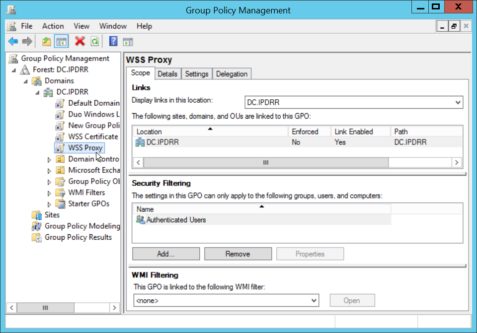
2.2.3 Configure Symantec Web Security Service Proxy
Navigate to the Connectivity tab.
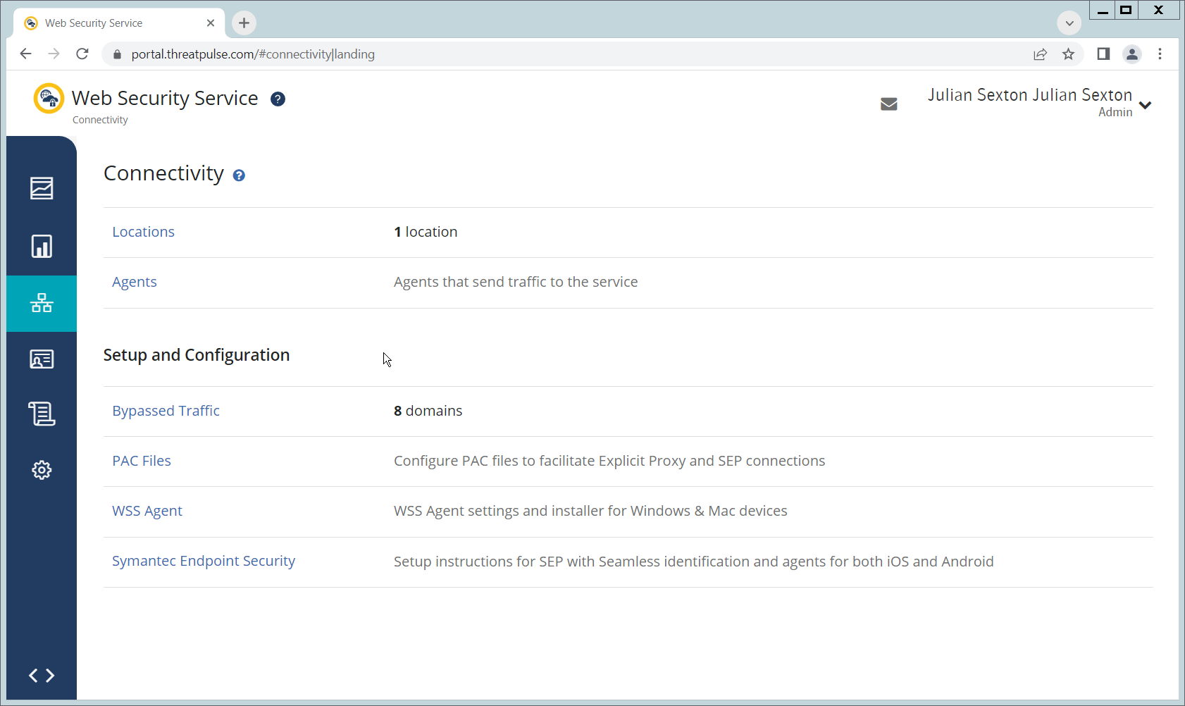
Click Locations.
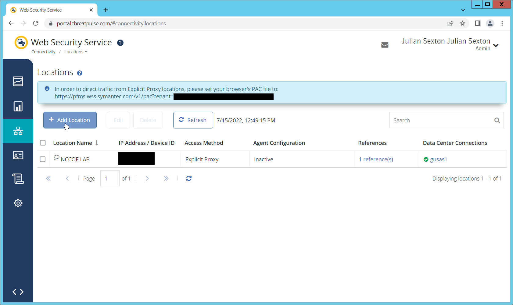
Click Add Location.
Enter a name for the Location.
Select Proxy Forwarding for Access Method.
Enter any public IP addresses of your organization, to ensure that traffic sent through the WSS (Web Security Service) proxy is redirected to the proper dashboard.
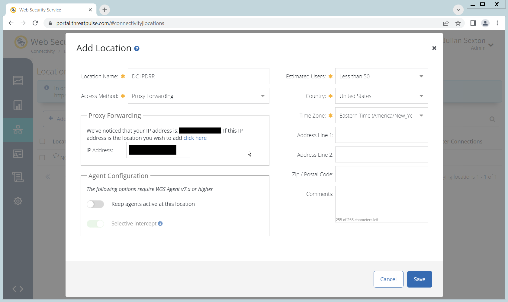
Click Save.
This page will now provide a URL to a PAC file that can be distributed to browsers across the organization via GPO. If you wish to create a custom PAC file, you can navigate to Connectivity > PAC Files.
Open the Group Policy Management Console.
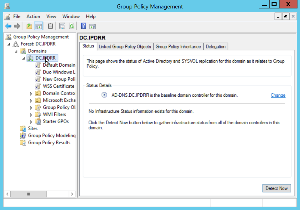
Right click the Domain and select Create a GPO in this domain, and Link it here….
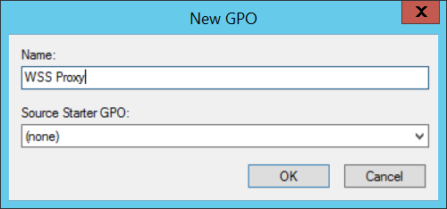
Enter a name and click OK.
Right click the newly created GPO and click Edit….
Navigate to User Configuration > Preferences > Control Panel Settings.
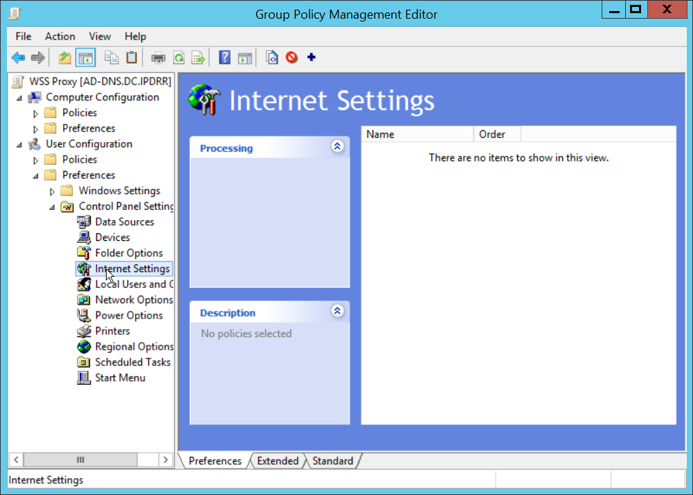
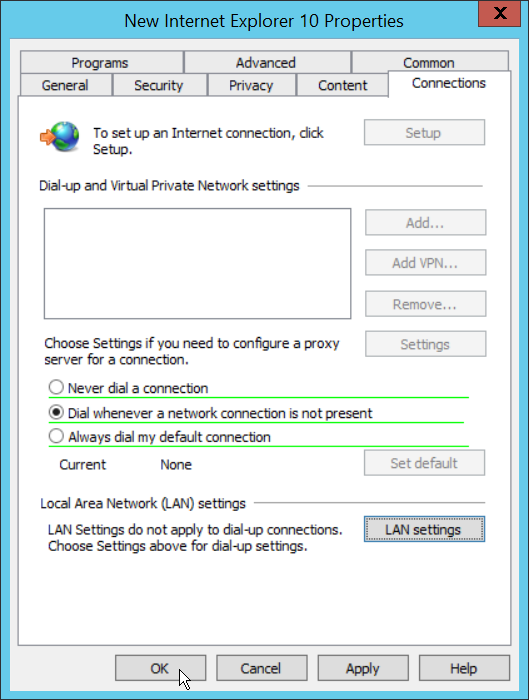
Right click Internet Settings and select New > Internet Explorer 10 Properties.
Click the Connections Tab.
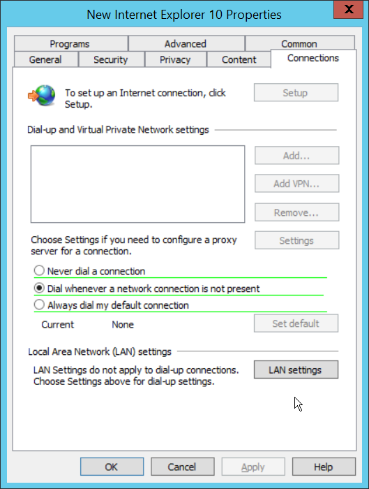
Click Local Area Network (LAN Settings).
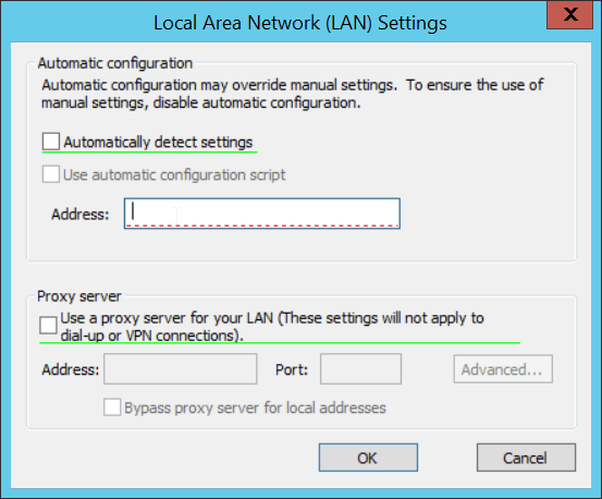
Select the Address field.
Press F6 to enable it (it is enabled if the box has a solid green underline.
Enter the PAC file URL from earlier in the Address field.
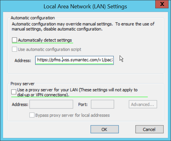
Click OK.
Click OK.
To verify that traffic is going through Isolation, you can visit the following test website, and substitute 1-10 for the threat level: http://testrating.webfilter.bluecoat.com/threatrisk/level/7.
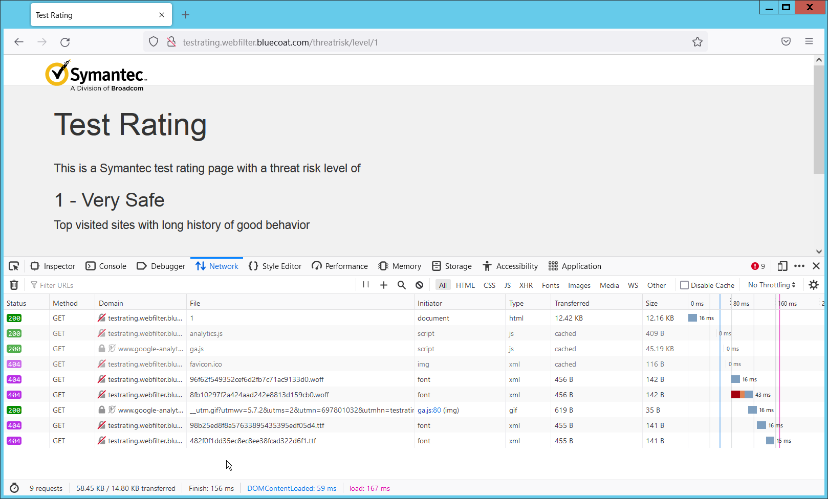
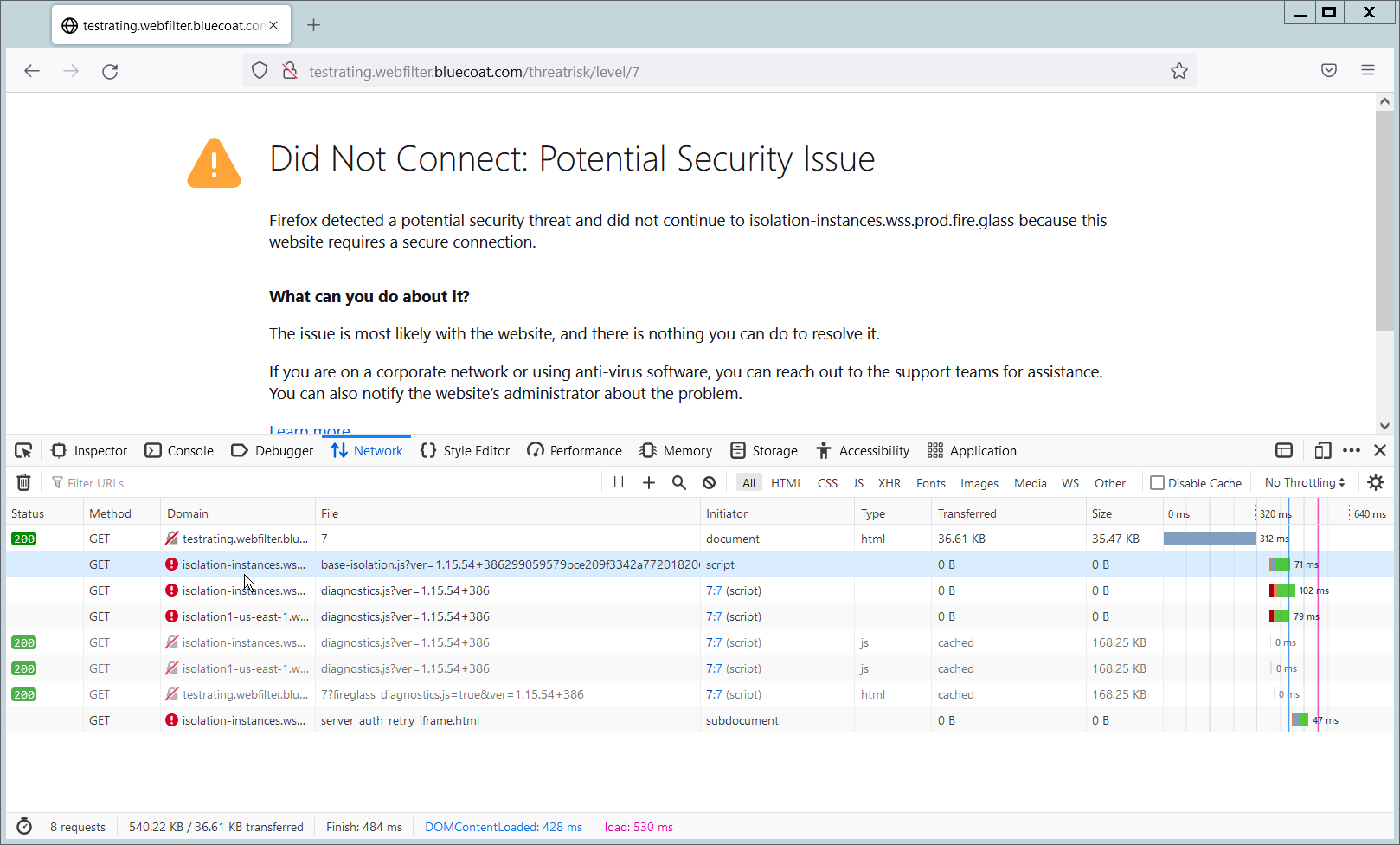
On this test URL (tested July 2022), levels 5-7 will go through isolation, and you will be able to see the isolation traffic from the network tab in developer mode (F12) on the browser. Levels 8-10 will be blocked by the content filter, and levels 1-4 will not go through isolation or content filtering.
2.3 PKWARE PKProtect
This installation and configuration guide for PKWARE PKProtect uses a physical PKWARE server, and as such will not delve into the installation of server components. In this guide, PKWARE is used to automatically perform data inventory and data protection functions. PKWARE provides users with the ability to store encrypted files for retrieval later, requiring the use of user credentials to access them.
2.3.1 Configure PKWARE with Active Directory
Login to the PKWARE web portal using the administrative credentials.
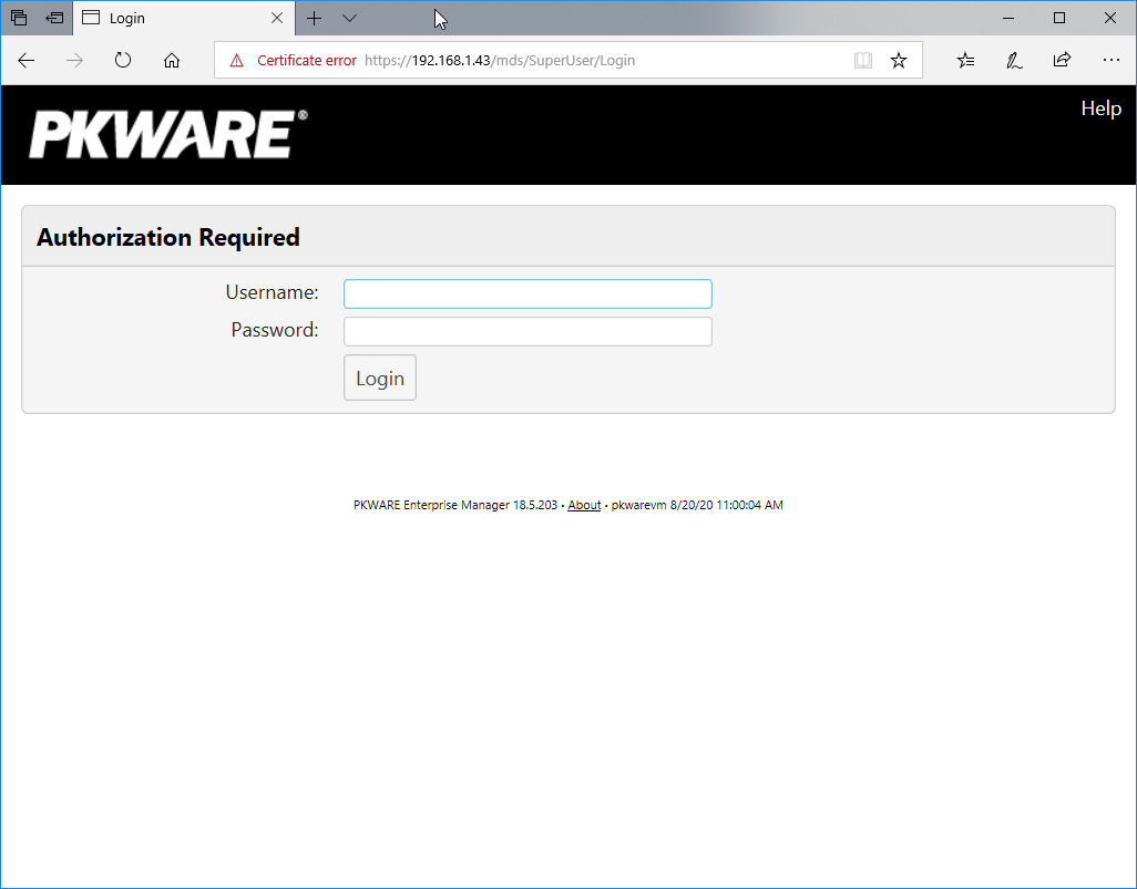
Once logged in, you can and should change the password to this administrative account by clicking Change Password in the top right corner.
Navigate to System > Domain.
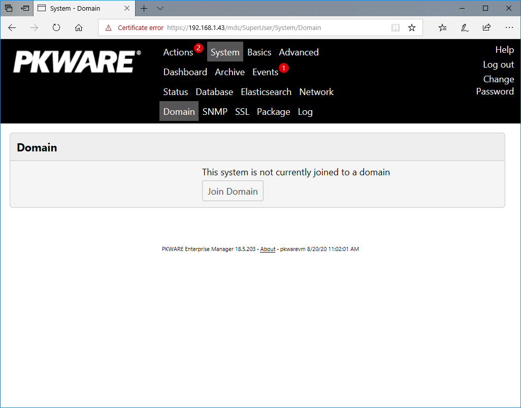
Click Join Domain.
Enter the Kerberos Realm, NetBIOS Domain, as well as the username and password of an administrative user on the domain.
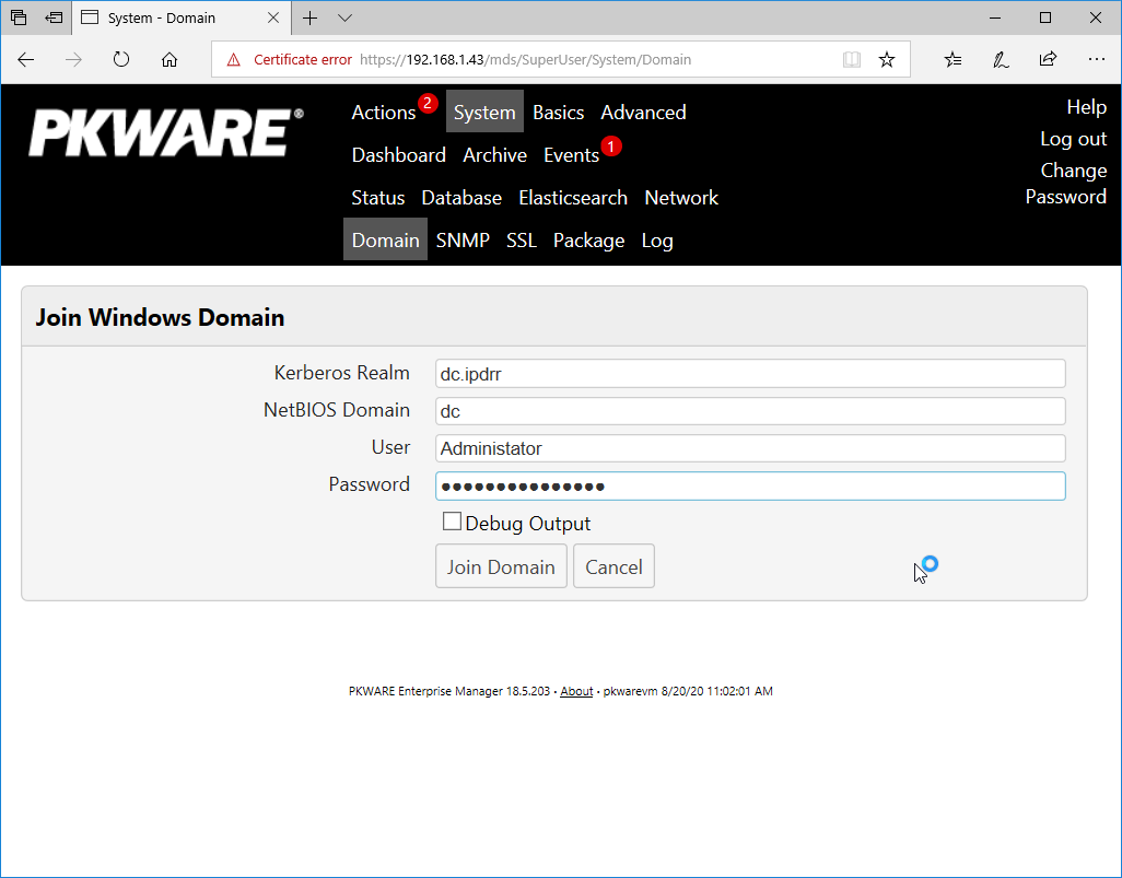
Click Join Domain.
2.3.2 Create a New Administrative User
Navigate to Advanced > Admins.
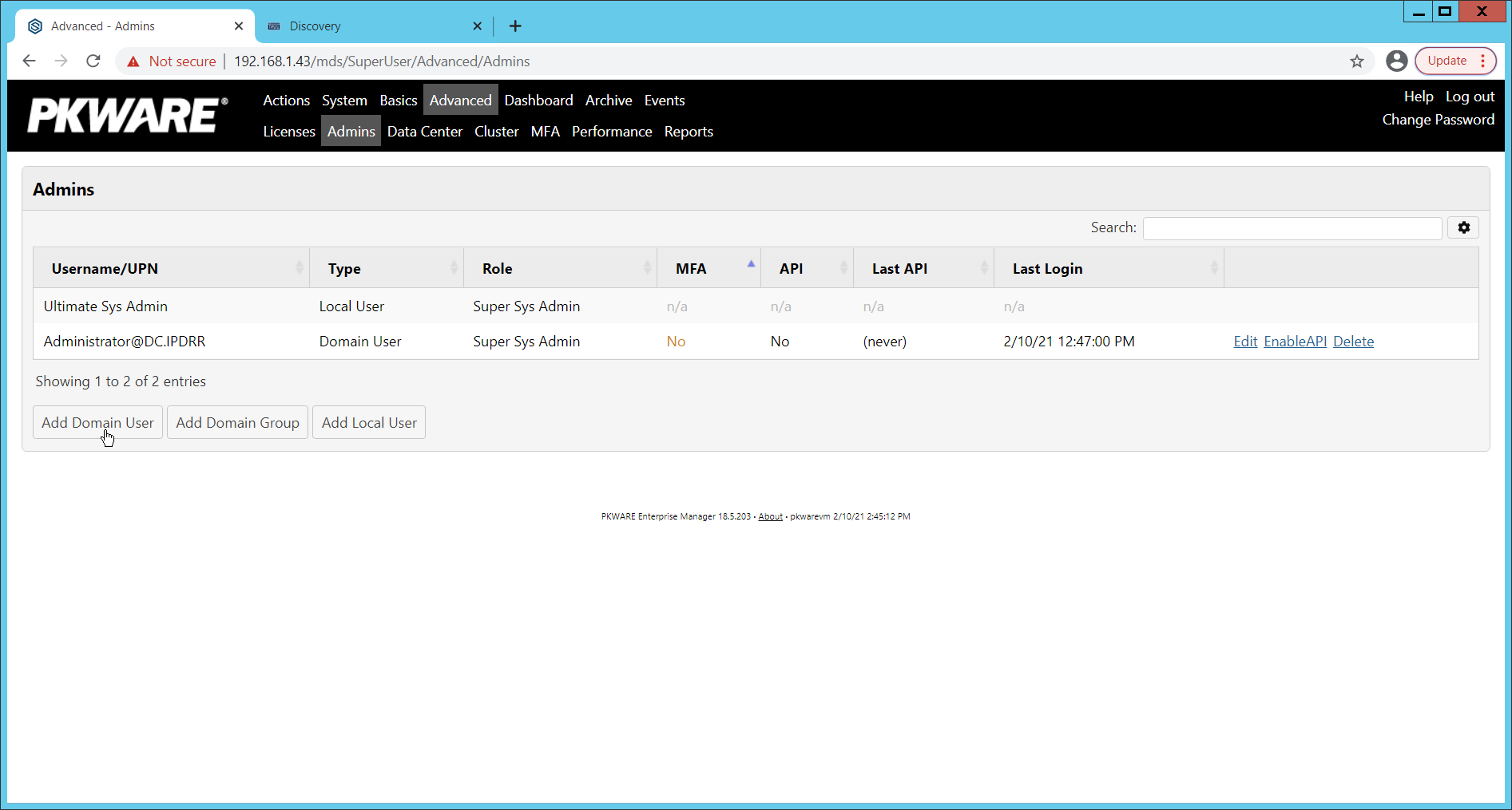
Click Add Domain User.
Enter the username of a user on the domain that should be able to login through the PKWARE management portal (this is meant for administrators only).
Select the level of permissions the user should have.
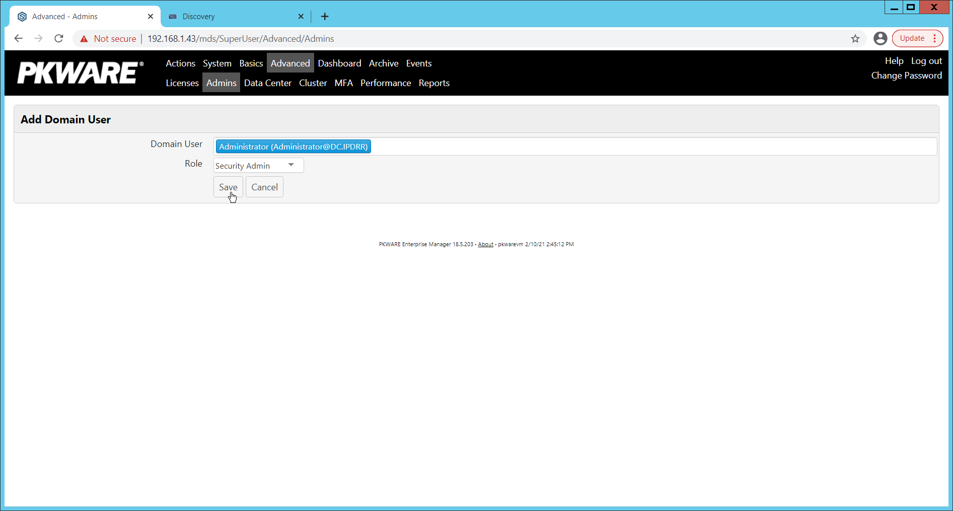
Click Save.
2.3.3 Install Prerequisites
If needed for your environment, you may need to install certificates locally before agents can connect to PKProtect - ask your PKWARE representative if this is necessary for your environment.
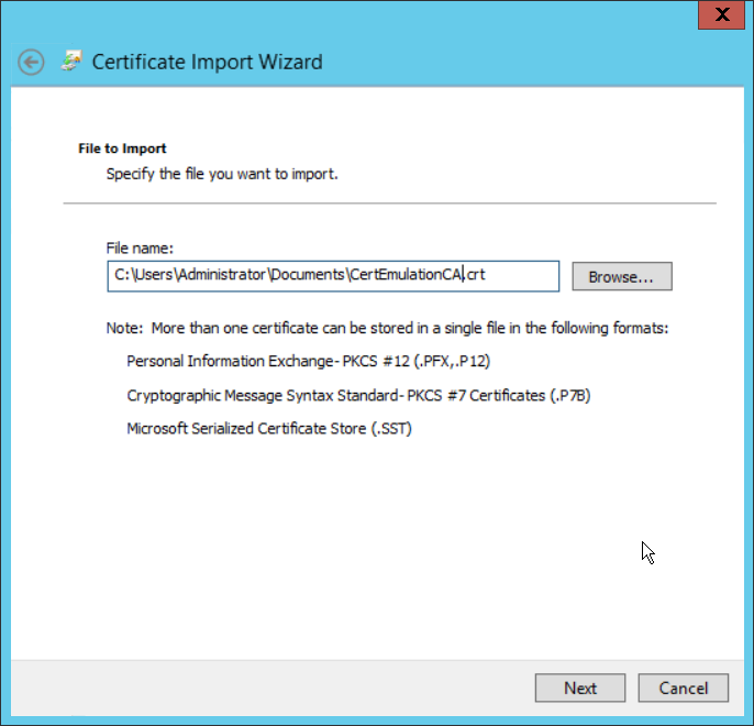
Double click the certificate you wish to install.
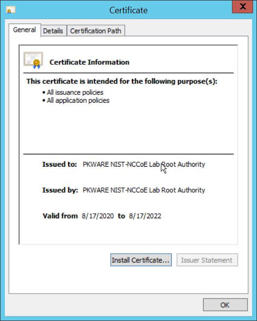
Click Install Certificate…
Select Current User.
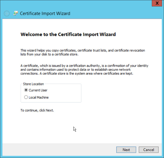
Click Next.
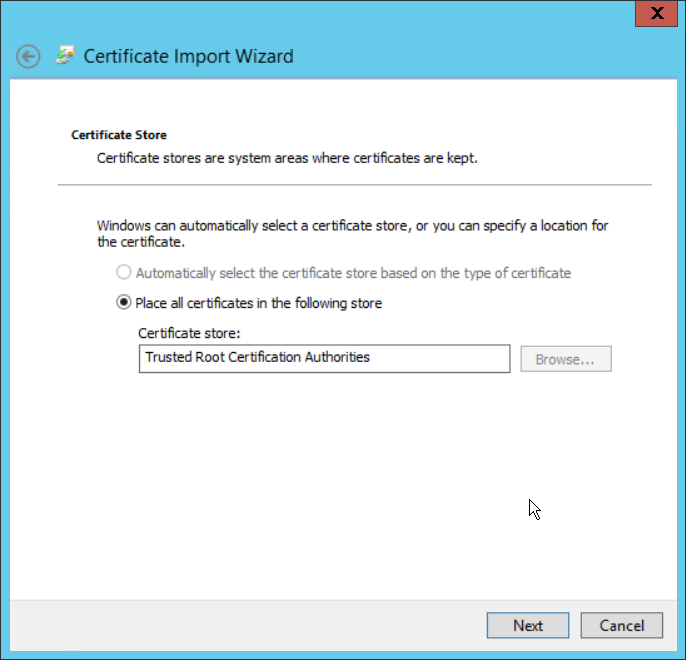
Click Browse.
Select Trusted Root Certification Authorities.
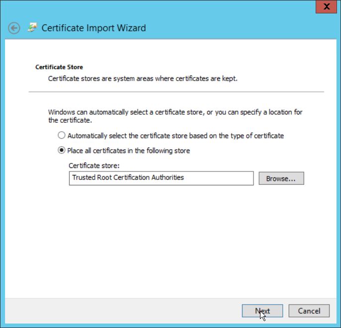
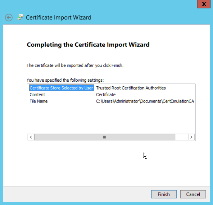
Click Next.
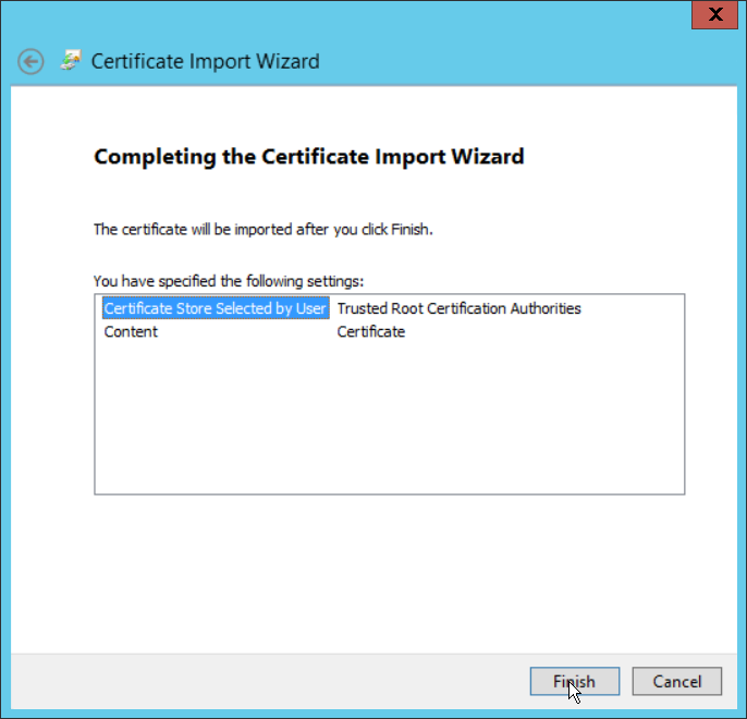
Click Finish.

Click OK.
Repeat steps 1 through 10 but select Personal instead of Trusted Root Certification Authorities.
Repeat steps 1 through 11 for each certificate that needs to be installed.
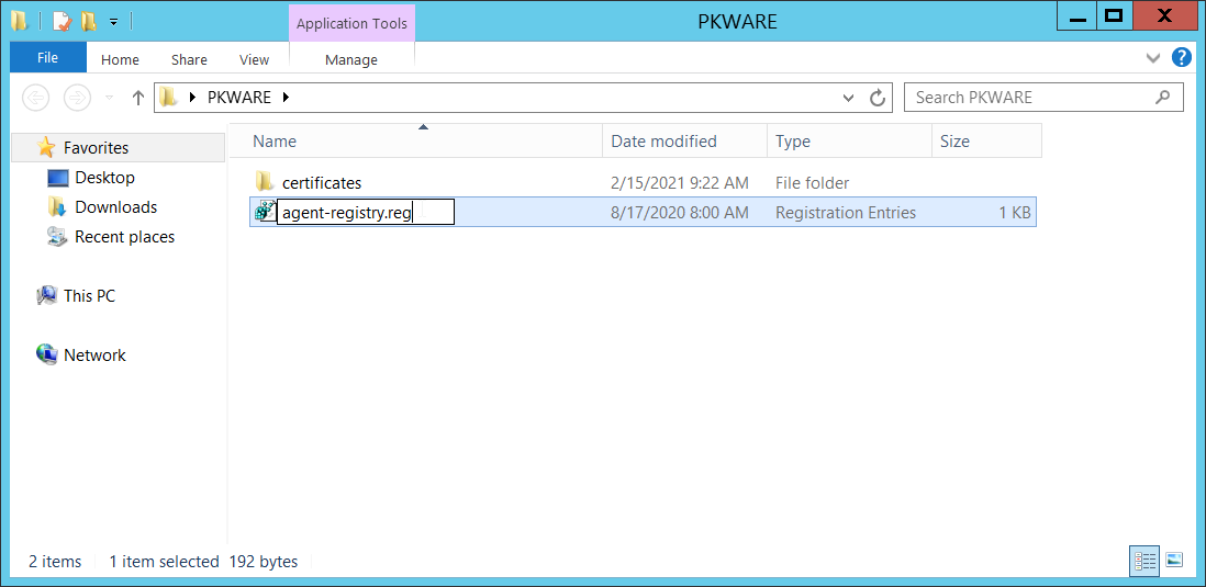
Rename agent-registry.txt to agent-registry.reg.
Double click the file (must have administrator privileges).
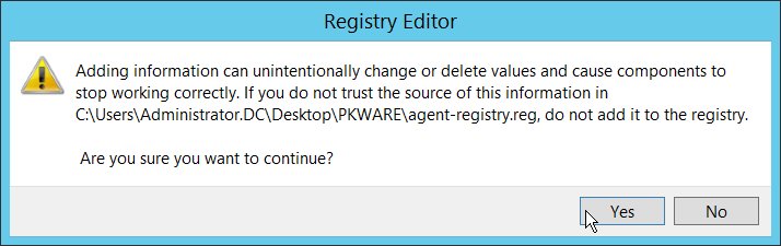
Click Yes.
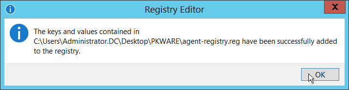
Click OK.
Restart the machine to apply these changes.
2.3.4 Install the PKProtect Agent
Run the PKProtect Installation executable.
Click Next.
Select I accept the terms in the license agreement.
Click Next.
Select Typical.
Click Next.
Click Install.
Click Finish.
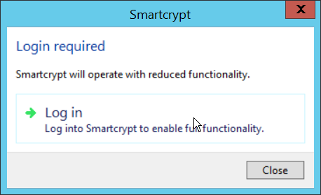
If a window to login is not automatically shown, you can right click the PKProtect icon in the Windows taskbar and click Login…. If a window is automatically shown, click Log in.
Login using the username of the account in the domain, in email format (such as administrator@domain.id).
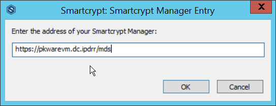
Enter the address of the PKWARE server.
The PKWARE agent will now run in the background.
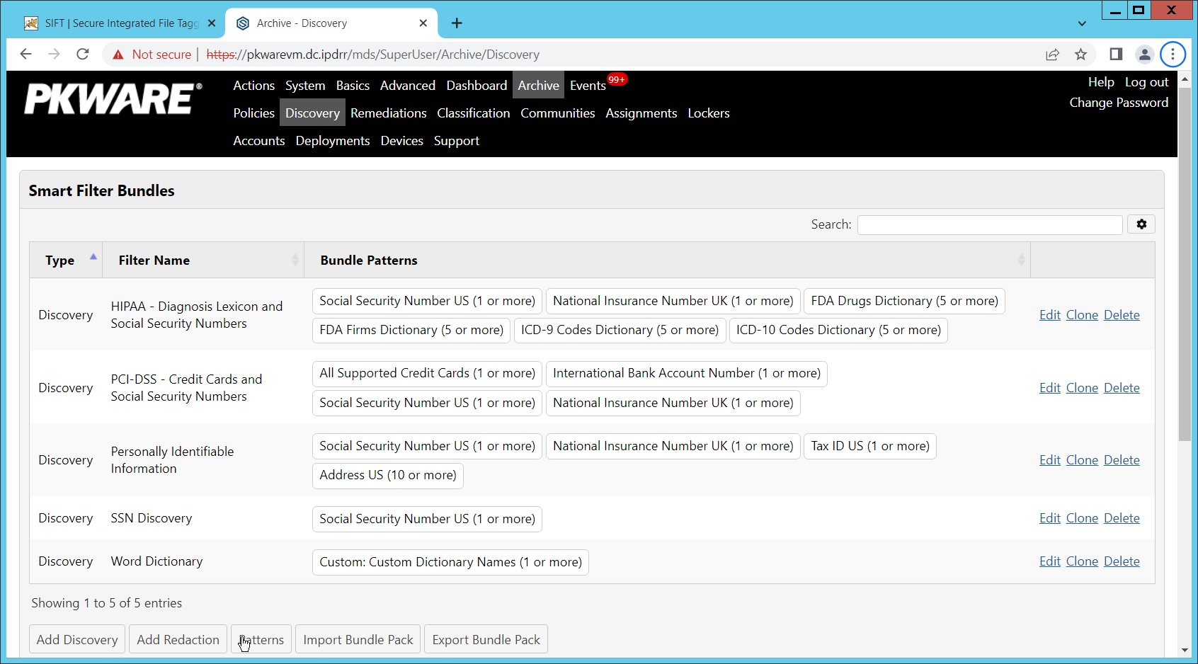
2.3.5 Configure Discovery and Reporting
On the PKWARE dashboard, log in as an administrative user, and navigate to Archive > Discovery.
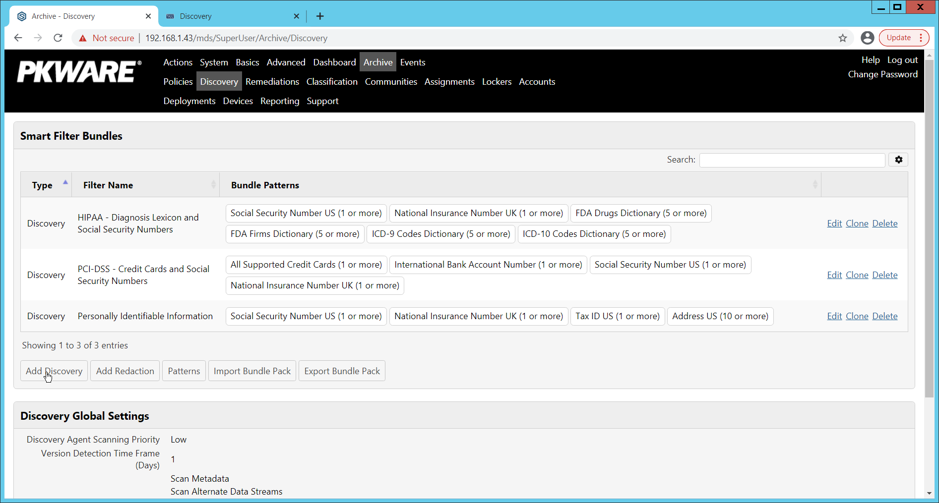
Click Add Discovery.
Enter a name for the discovery rule.
Select a pattern for the rule to discover. In this case, we are setting up a rule to detect social security numbers in files for reporting/remediation.
The Threshold field refers to how many of those patterns must be present in a document for the rule to be applied.
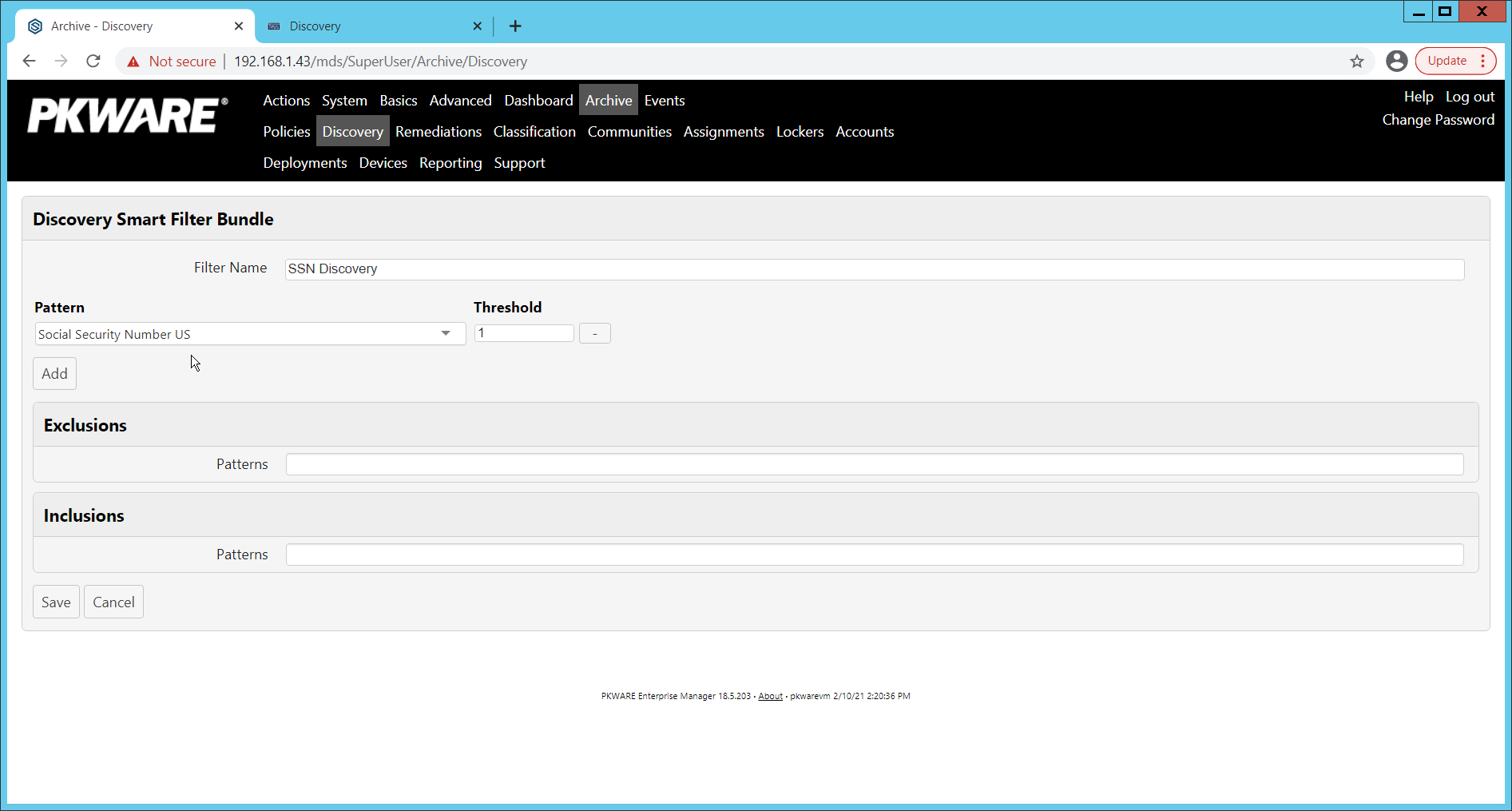
Click Save.
Navigate to Archive > Remediations.
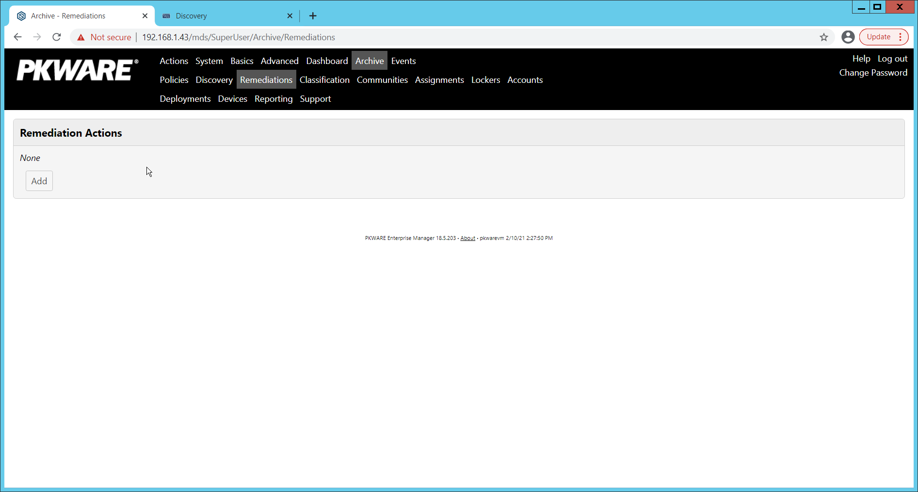
Click Add.
Enter a name for the remediation.
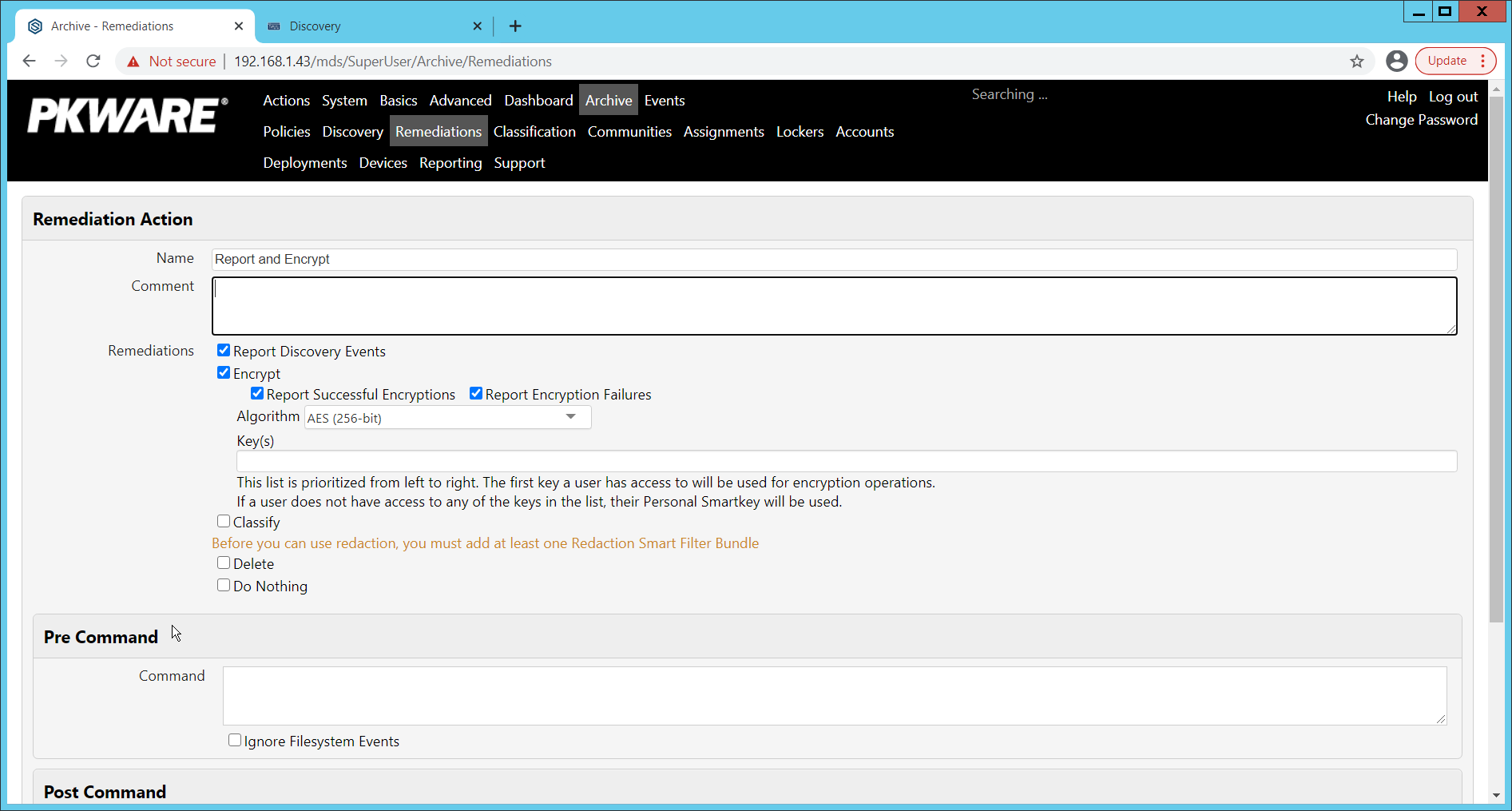
Check the box next to Report Discovery Events.
Check the box next to Encrypt.
Ensure that AES (256-bit) is selected.
Click Save.
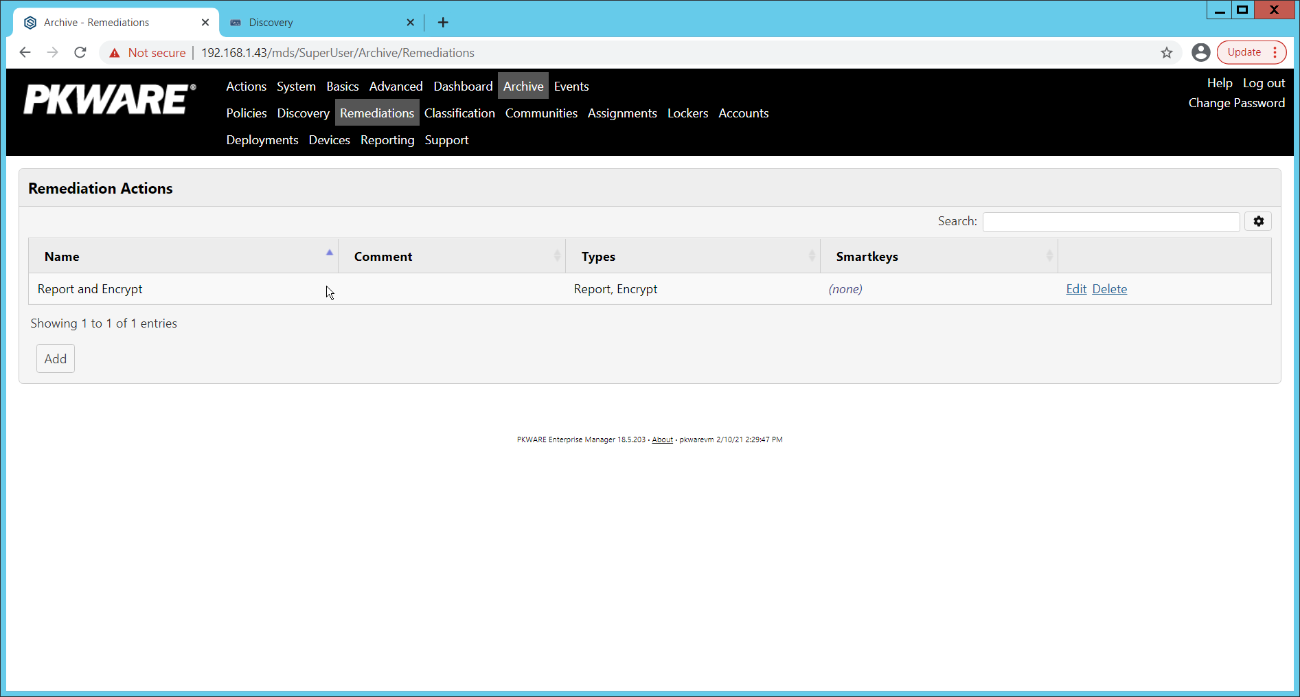
Navigate to Archive > Assignments.
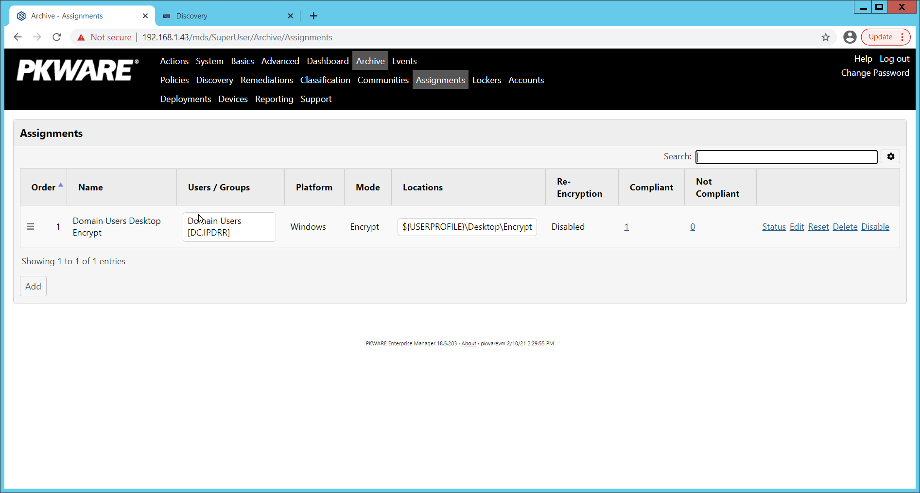
Click Add.
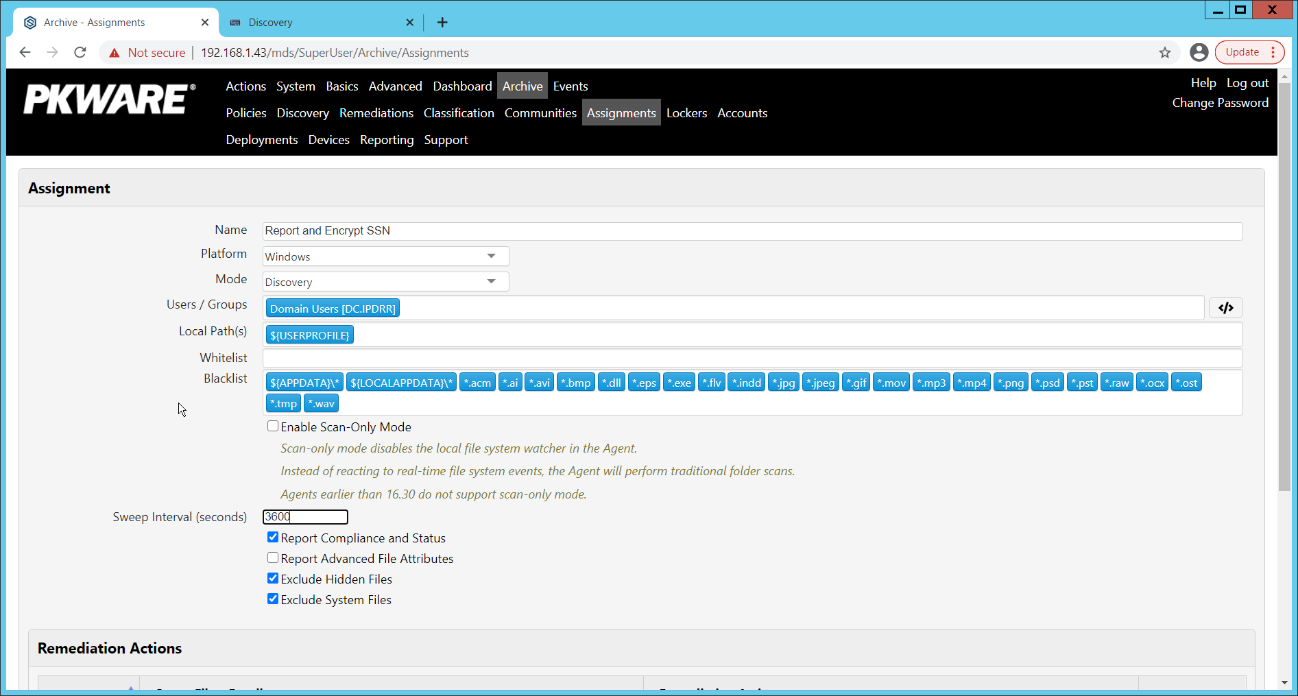
Enter a name for the Assignment.
Select the Platform for this assignment to run on.
Select Discovery for the Mode.
Enter the names of the Active Directory users or groups this rule should apply to.
Enter the folders for this rule to search in Local Paths.
Use Whitelist and Blacklist to specify file types that should or should not be considered.
Enter the interval for this rule to run in Sweep Interval.
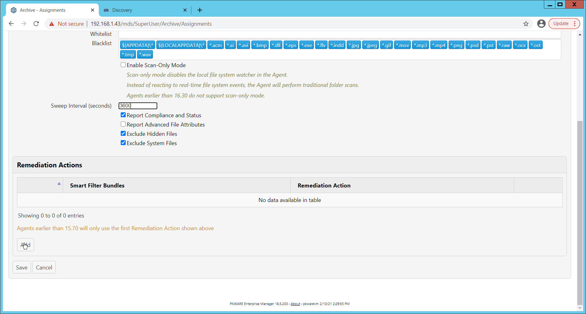
Under Remediation Actions, click Add.
Select the Discovery rule created earlier under Smart Filter Bundles.
Select the Remediation Action created earlier under Remediation Action.
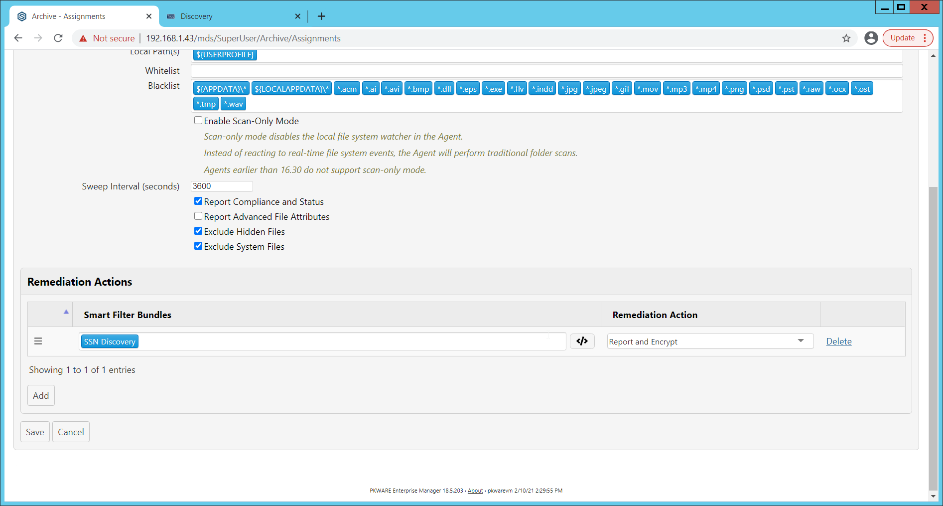
Click Save.
This rule will now run automatically, reporting and encrypting files that match its discovery conditions.
2.4 StrongKey Tellaro
StrongKey is a Representational State Transfer (REST) Application Programming Interface (API) providing various security services. In this project, we primarily make use of its file encryption capabilities in the context of data protection. Because it is a web service, there is not much installation required on the enterprise side, and the bulk of the setup is acquiring credentials to communicate safely with the API. In this build, Strongkey will primarily be used for integration with other products, to encrypt sensitive data generated by products in formats that may be otherwise difficult to encrypt.
2.4.1 Python Client for StrongKey – Windows Executable Creation and Use
Ensure that the following script (see end of section) is filled out with information specific to your enterprise, including the variables skdid, skuser, and skpass.
Save the file as strongkey-client.py.
This example will demonstrate how to create an executable from the script below. Download Python 3.8.0 from the Python website: https://www.python.org/downloads/release/python-380/. Specifically, download the Windows x86 executable installer. The 32-bit version will provide better access to Active Directory packages and interfaces.
Run the installer.
Check the box next to Add Python 3.8 to PATH.
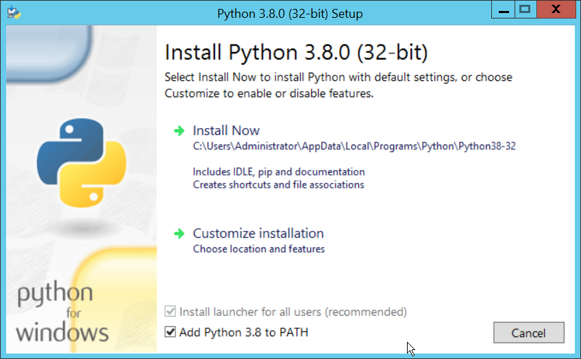
Click Install Now.
Click Close.
Open a PowerShell window.
Run the following command to install pyinstaller.
> pip install pyinstaller
Run the following command to install requests.
> pip install requests
From the PowerShell window, navigate to where you saved strongkey-client.py.
Run the following command to build the client into an executable.
> pyinstaller --onefile .\strongkey-client.py
A folder called dist will be created. In this folder will be an executable named strongkey-client.exe.
To encrypt a file in place (i.e., overwrite the file with encrypted contents), run the following command:
> ./strongkey-client.exe -encrypt -overwrite --infile sensitive.txt
To encrypt a file and save it to a new location, run the following command:
> ./strongkey-client.exe -encrypt --outfile encrypted.txt --infile sensitive.txt
To decrypt a file in place (i.e., overwrite the encrypted file with plaintext contents), run the following command:
> ./strongkey-client.exe -decrypt -overwrite --infile sensitive.txt
To decrypt a file and save it to a new location, run the following command:
> ./strongkey-client.exe -decrypt --outfile decrypted.txt --infile encrypted.txt
This client can be configured to run on a schedule, or be iterated over a directory of files, depending on the needs of the organization. Because the client is Python and StrongKey is REST API based, the script is adaptable to various architectures and can be deployed widely across the enterprises, to fill in gaps that the enterprise may have in its data protection capabilities.
import requests
import json
import argparse

skdid = # Note: Users should reference a separate file for this ID
skuser = # Note: Users should reference a separate file for the username
skpass = # Note: Users should reference a separate file for the password
encurl = "https://demo4.strongkey.com/skee/rest/encrypt"
decurl = "https://demo4.strongkey.com/skee/rest/decrypt"

def buildrequest(fname, encrypt):
    req = {}
    req["svcinfo"] = {
        "did": skdid,
        "svcusername":skuser,
        "svcpassword":skpass
    }

if (encrypt):
    req["encinfo"] = {
        "algorithm": "AES",
        "keysize":256,
        "uniquekey":TRUE
    }

    req["fileinfo"] = {
        "filename": name
    }

    req["authzinfo"] = {
        "username": "encryptdecrypt",
        #"userdn": "cn=encryptdecrypt,did="+skdid+",ou=users,ou=v2,ou=SKCE,ou=StrongAuth,ou=Applications,dc=strongauth,dc=com", "authgroups": "cn=EncryptionAuthorized,did="+skdid+",ou=groups,ou=v2,ou=SKCE,ou=StrongAuth,ou=Applications,dc=strongauth,dc=com", "requiredauthorization": 0
    }

    req["svcinfo"] = json.dumps(req["svcinfo"])
    req["fileinfo"] = json.dumps(req["fileinfo"])
    if (encrypt):
        req["encinfo"] = json.dumps(req["encinfo"])
    req["authzinfo"] = json.dumps(req["authzinfo"])

    return req

def encrypt(filename,output,overwrite):
    req = buildrequest(filename, True)
    with open(filename, mode='rb') as f:
        files = [('filedata', f)]
        p = requests.request("POST", encurl, headers={}, data=req, files=files)
    print(p)
    p.raise_for_status()
    if (p.status_code == 200):
        output = filename if overwrite else output
        with open(output, mode='wb') as o:
            o.write(p.content)

def decrypt(filename,out,overwrite):
    req = buildrequest(filename, False)
    with open(filename, mode='rb') as f:
        files = [('filedata', f)]
        p = requests.request("POST", decurl, headers={}, data=req, files=files)
    p.raise_for_status()
    if (p.status_code == 200):
        output = filename if overwrite else out
        with open(output, mode='wb') as o:
            o.write(p.content)

parser = argparse.ArgumentParser(description='Encrypt or decrypt a file using Strongkey.')

group = parser.add_mutually_exclusive_group(required=True)
group.add_argument("-encrypt", action='store_true')
group.add_argument("-decrypt", action='store_true')

group = parser.add_mutually_exclusive_group(required=True)
group.add_argument("-overwrite", action='store_true')
group.add_argument("--outfile", type=str)

parser.add_argument("--infile", type=str, required=True)

a = parser.parse_args()

if (a.overwrite is True): overwrite = True
    out = ""
elif (a.outfile is not None):
    out = a.outfile
    overwrite = False

if (a.encrypt is True):
    encrypt(a.infile, out, overwrite)
elif (a.decrypt is True):
    decrypt(a.infile, out, overwrite)
2.5 Qcor ForceField
ForceField is a Write-Protected File System (WFS) combining hardware device security and encryption. In this build, ForceField is primarily used to backup data while maintaining confidentiality through encryption. In this build, we used ForceField for the protection of a transactional database that needs to maintain both the confidentiality and integrity of prior transactions, while still affording the ability to use that data in new transactions.
2.5.1 Installation and Usage of ForceField
Either a Compact Disk (CD) or zip file will be provided by Qcor containing the WFS API and associate utilities. Copy the contents of \GreenTec\Release onto the C: drive of the Qcor ForceField server.
Add the destination folder to the command line PATH variable if necessary. To do this, from the start menu search for Environment Variables.
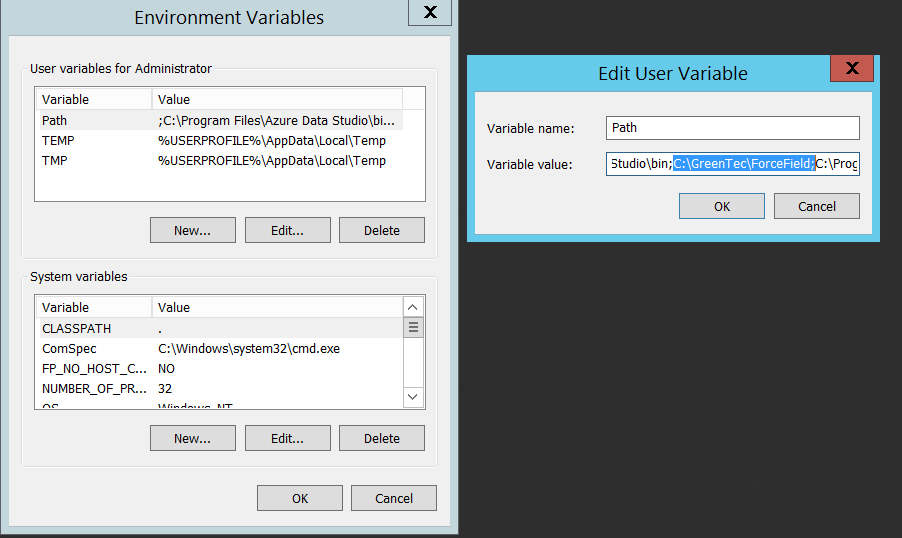
Double click the Path variable and add the path to the WFS API.
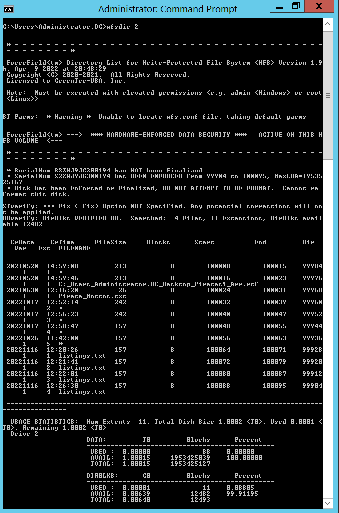
Verify that the drives of the Qcor WFS server have been formatted to work with ForceField with wfsdir command line utility that was just installed. The drives may be pre-formatted. Use the following command to determine whether a drive is formatted. In place of “N”, enter the number of the drive to check.
> wfsdir N
If the hard drive(s) have not been formatted, use the wfsx command line tool to format your drive. Note: Once performed, the formatting cannot be undone. The following instructions are copied from the WFS User Guide.
\> wfsfx <devicename> <options>\devicenameis the device identifier of the disk to be formatted. For Windows, this is the Windows disk number that may be found via the Windows Disk Manager (e.g. 1, 2, etc.). For Linux, this is the physical device name (e.g. /dev/sdb/).optionsmay be:-DirXor-x <power of 10>(optional power of 10 for max number of files, default is 10) 1 will format for 1,243 files, 10 will allow 12,489 files, 100 allows 124,993 files, 1000 allows 1,249,930 files-vuser <username>specifies a volume user name, DO NOT FORGET THIS USE NAME IF USED!-vpass <password>specifies a volume password, DO NOT FORGET THIS PASSWORD IF USED!-cache ON|OFFwill turn on or off the disk drive internal cache (default is ON).-verifywrite ON|OFFwill turn write verify on or off for the WFS volume (default is OFF). The write verify status may be toggled ON or OFF using the WFScache utility. NOTE: turning write verify ON may significantly degradeI/O performance.Files can then be copied into or out of the designated drives using the wfscopy command line tool. The following instructions are copied from the WFS User Guide.
> wfscopy <source-file> <destination-file> <count>
One of the files must be a native Operating System (OS) file system file, and the other file must be a WFS file. source-file is the name of the input file and may be a native OS filename, or a WFS filename. destination-file is the name of the input file and may be a native OS filename, or a WFS filename. count is the optional number of bytes to copied. count defaults to all records.
Examples of wfscopy using Windows:
> wfscopy testfile.txt 1:*
The above command will copy the file named testfile.txt from the local directory to disk number 1 with the same name. If the WFS file does not previously exist, then it is created. If the WFS file does previously exist, then the data is appended to the existing WFS file as a new file extension.
> wfscopy 2:Contracts.pdf c:\myfolder\Contracts.pdf
The above command will copy all records from all extensions of the WFS file named Contract.pdf from the disk, as identified as 2 by the Windows Disk Manager, to the Windows file C:\myfolder\Contracts.pdf record by record.
> wfscopy 4:myfile.txt con:
The above command will display the contents of the WFS file myfile.txt from disk 4 onto the console. This is similar to using the type command in the Windows command line.
2.6 Avrio SIFT
Avrio SIFT is a data inventory and management capability designed to enforce data policies. The installation of Avrio SIFT is typically done in a managed fashion by the vendor, and the deployment seen in the NCCoE lab may not resemble other deployments. In the case of a Docker deployment, configuration to the base Avrio installation can be made by modifying the docker-compose file. Otherwise, it will be assumed that Avrio has been installed and configured properly for the enterprise by the vendor.
2.6.1 Configuring Avrio SIFT
Navigate to the SIFT dashboard (default address: http://IP-address:8080/sift/) and login.
Click Configuration.
Under Enclaves, enter two locations. First, the path to the public Windows share, and second, the path to the one protected by PKProtect. We will use this second path later in the integration between PKProtect and SIFT. In this example, DCIPDRR is the path to the public share, and PROTECTED is the path to the one protected by PKProtect. Enter user accounts that can access each share. In production, it is recommended to create a separate user account for SIFT to use to access these shares.
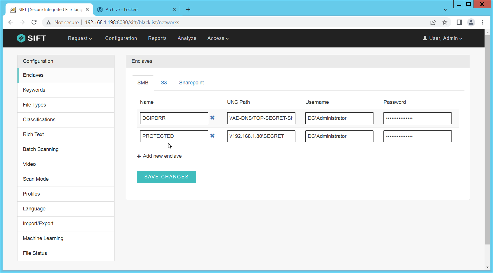
Click Save Changes.
Click Keywords on the left menu.
Click Add new keyword.
Enter the keyword under Name, and an Alias (if desired). Check the box next to any enclaves that are allowed to have this keyword – SIFT will be able to move files matching it to the enclaves you check the box for.
Select the PROTECTED enclave under Move To.
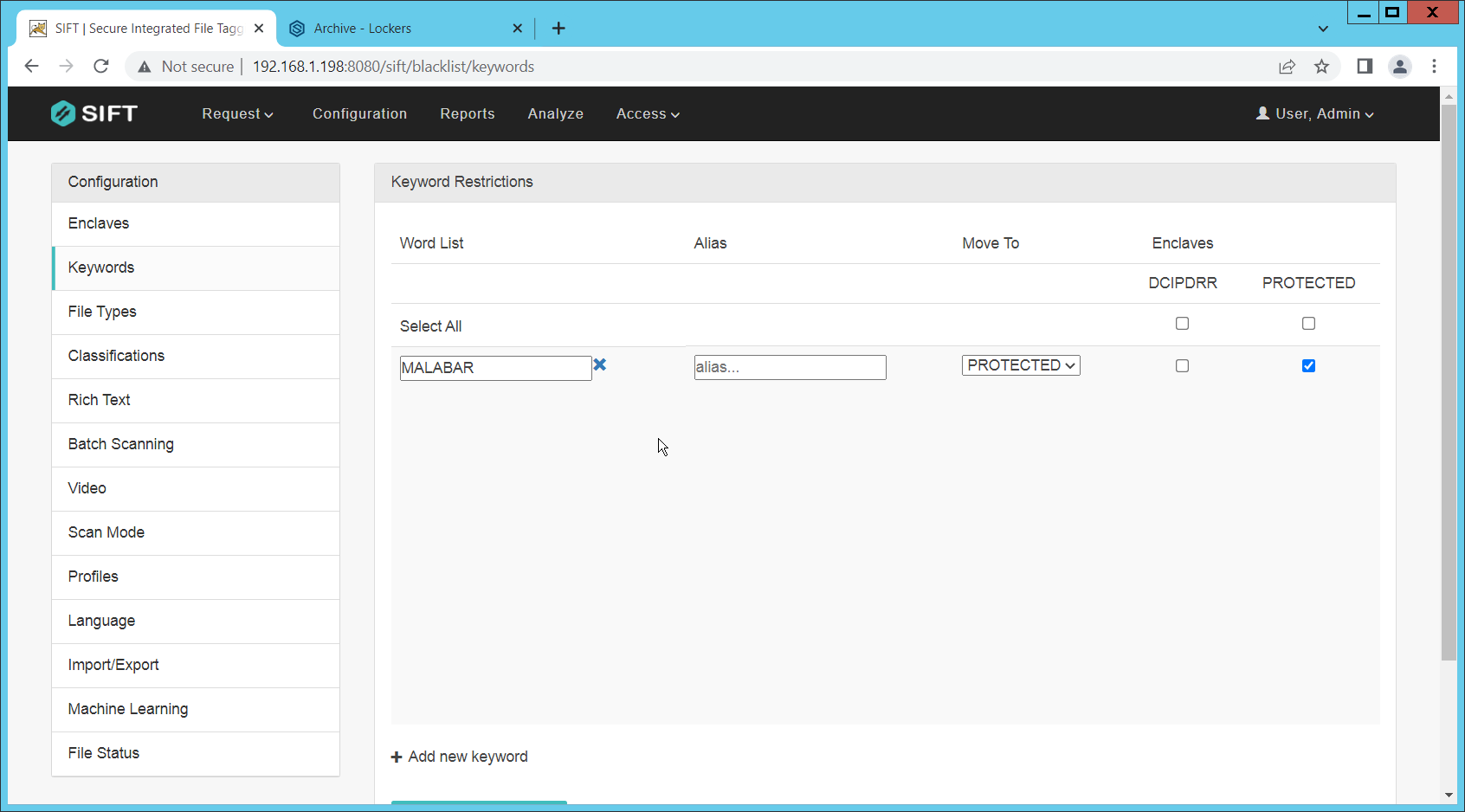
Click Save Changes.
Click File Types.
Designate file types that are allowed to exist under each enclave.
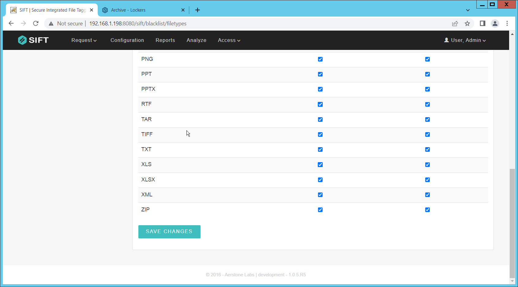
Click Save Changes.
Click Classifications.
Designate the classifications that are allowed to exist under each enclave.
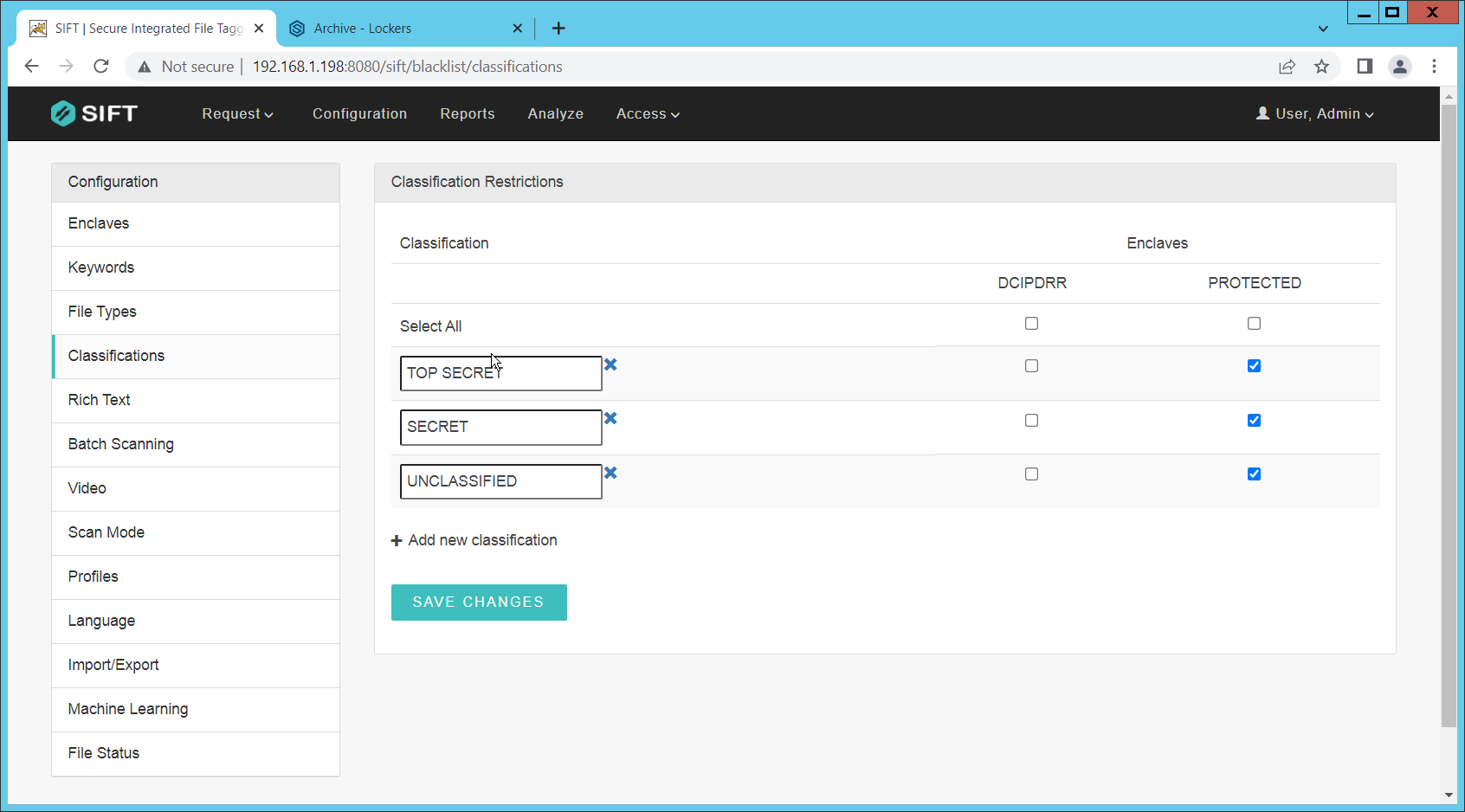
Click Save Changes.
On the top click Request > New Request.
Click Batch.
Select UNC Path for Source Type.
Select the enclave to scan for sensitive files.
Select Move for Scan Type. (Note that if you select Scan for Scan Type, it will scan files and tell you they are sensitive and whether they can be moved but will not attempt to move them. This is useful for debugging.)
Select Delete for Move Action, or another action depending on the needs of your organization. Selecting Delete will remove the sensitive file from the public share and move it to the protected one.
Set Scan Subfolders to ON.
Enter a description for the scan.
Set the frequency of the scan. Note that the efficiency of the scan will likely depend on the size of the organization, and it may be more desirable to scan once an hour rather than once a minute.
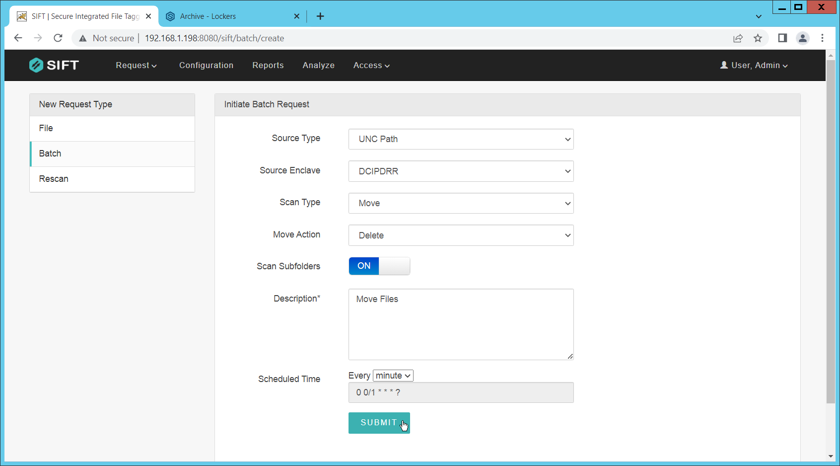
Click Submit.
Now, you can verify that files that are added to the public share with sensitive keywords are moved to the share designed to hold sensitive files.
2.7 Cisco Duo
Cisco Duo is a Multi-Factor Authentication and Single Sign-On tool. In this project, Dispel is used to control access to internal systems through virtualization, and Duo is used as a multifactor authentication solution between Dispel and those internal systems. This ensures that even if a Dispel virtual machine becomes compromised, there is still significant access control between that machine and the internal enterprise machines.
In the following section, we demonstrate the installation of Cisco Duo on an internal system in such a way that Remote Desktop Protocol (RDP) and local login to that system are protected by multifactor authentication.
2.7.1 Installing Cisco Duo
Begin by logging into the system you wish to protect with Duo.
Then connect to the internet, if not connected already, and go to the Duo Admin login page at https://admin.duosecurity.com/.
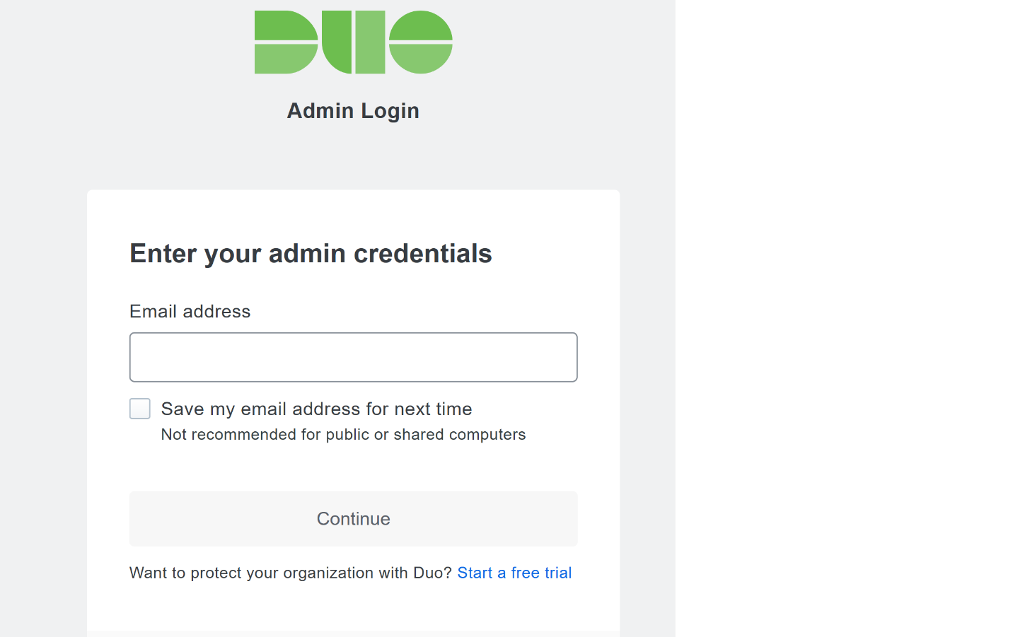
Login with your admin credentials and dual factor authentication until the admin dashboard is reached.
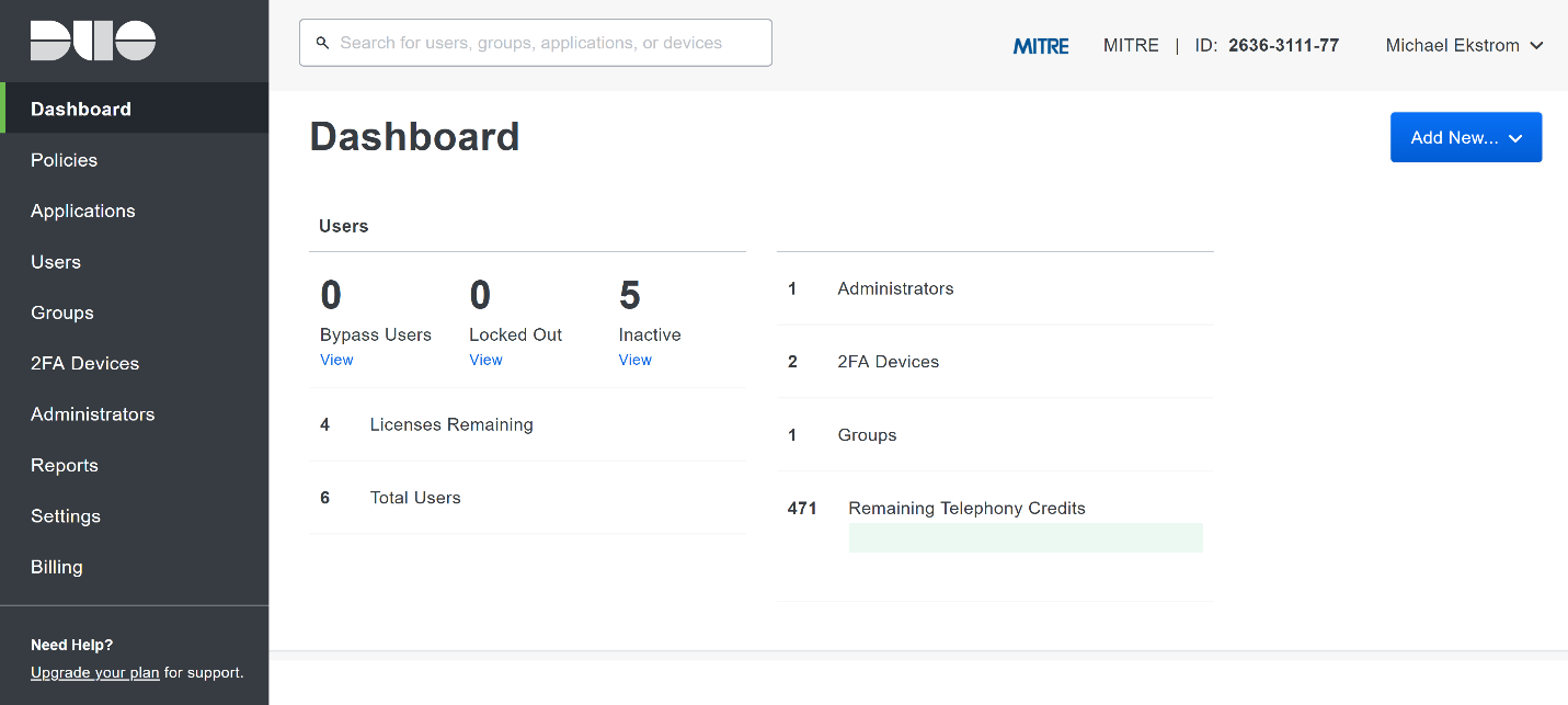
Click Applications in the sidebar.
Click Protect an Application.
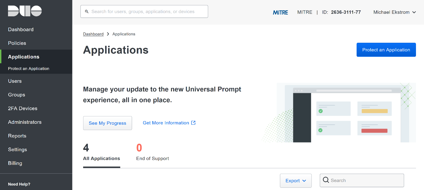
Search for, or scroll down to, Microsoft RDP.
Click Protect.
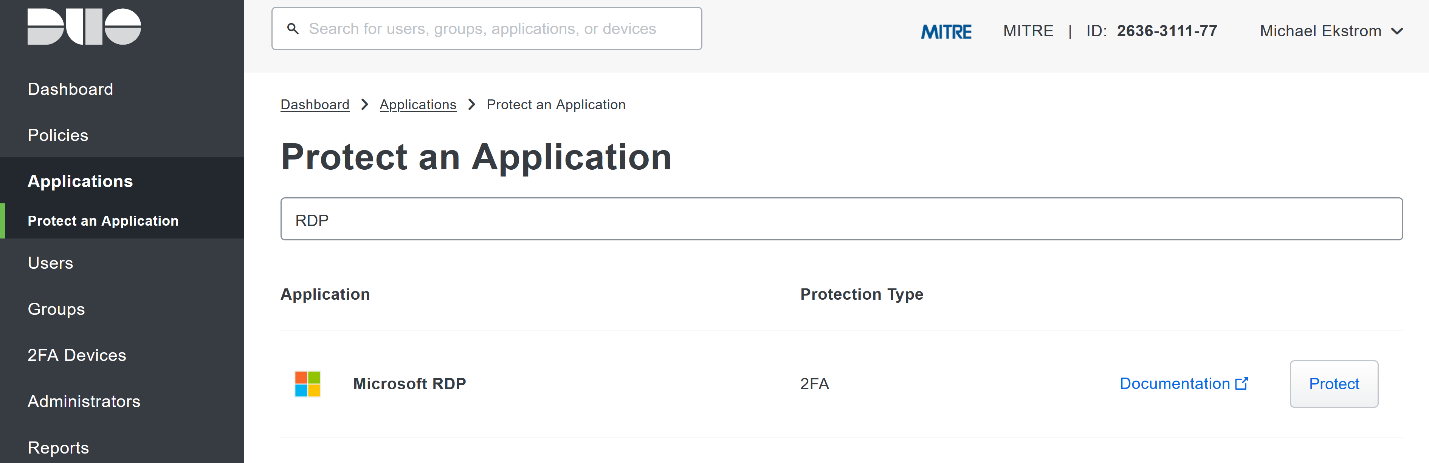
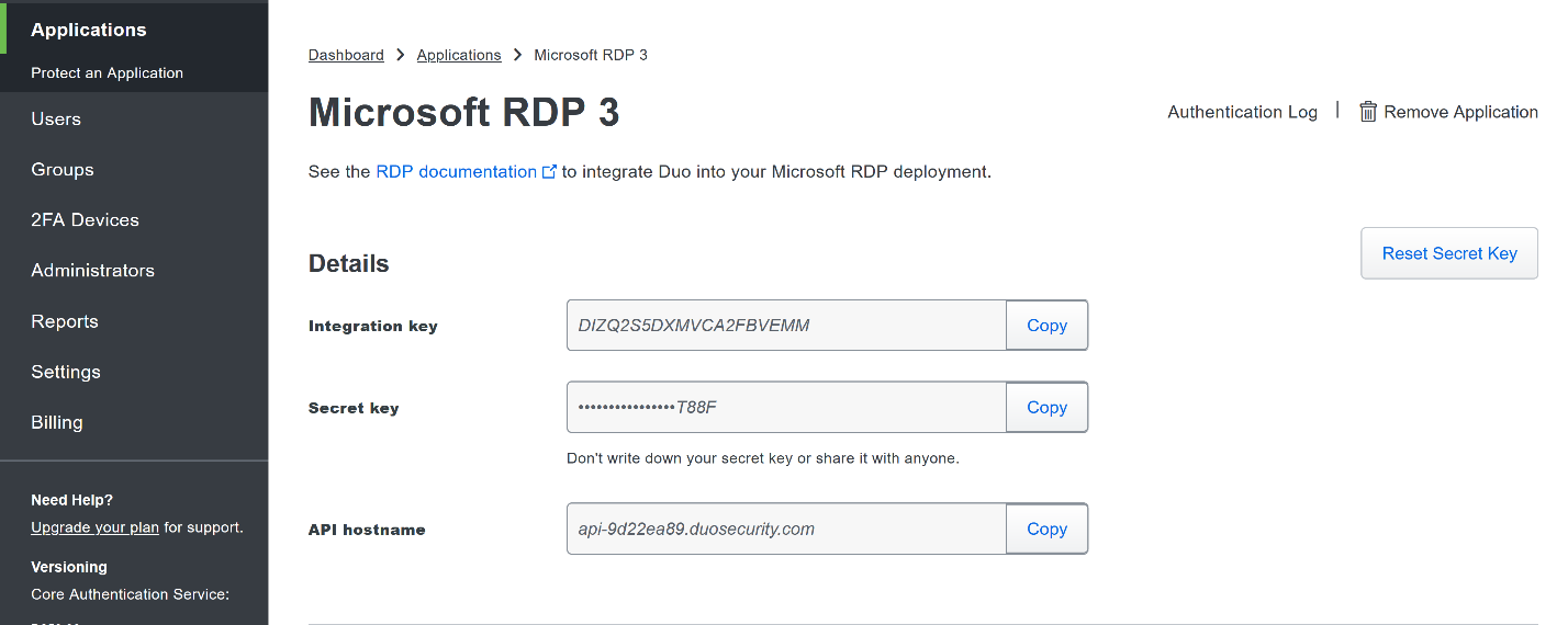
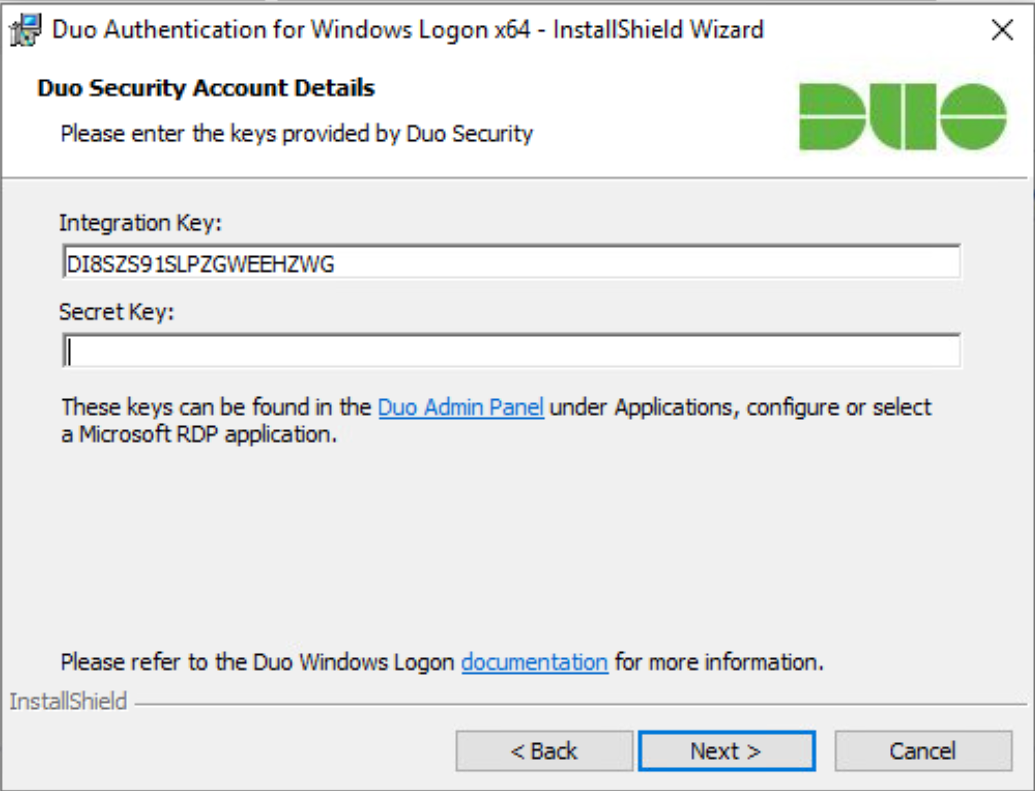
The next screen will provide policy configuration options, as well as the Integration Key, Secret Key, and API hostname, which are required information for the next step. Either keep this window open or copy down those three pieces of information.
Download the Duo Authentication for Windows Logon installer package, located at https://dl.duosecurity.com/duo-win-login-latest.exe.
Run the downloaded EXE file.
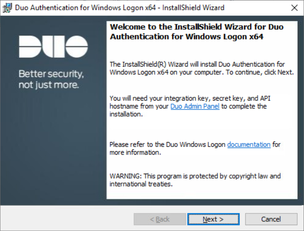
Click Next.
Copy the API Hostname into the labeled field.
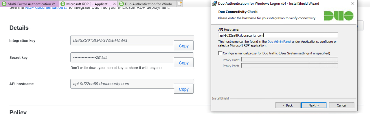
Click Next.
Copy in the Integration and Secret Keys into the relevant fields and click Next.
Click Next.
Configure Duo’s integration options according to the needs of your organization. Note that Bypass Duo authentication when offline will allow users to skip the two-factor authentication when offline, which increases the availability of their files but may increase risk.
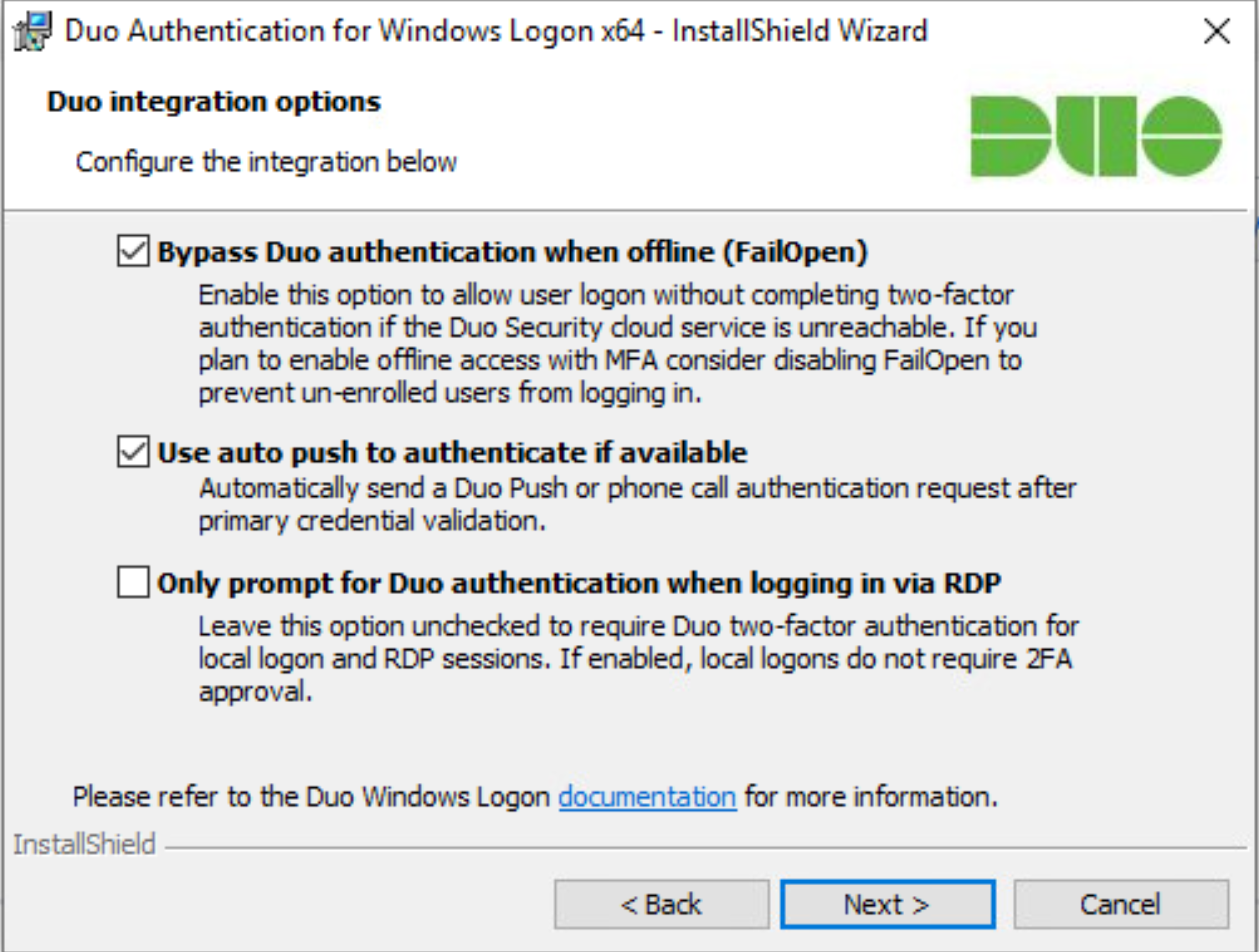
Click Next.
Leave Enable Smart Card support unchecked.
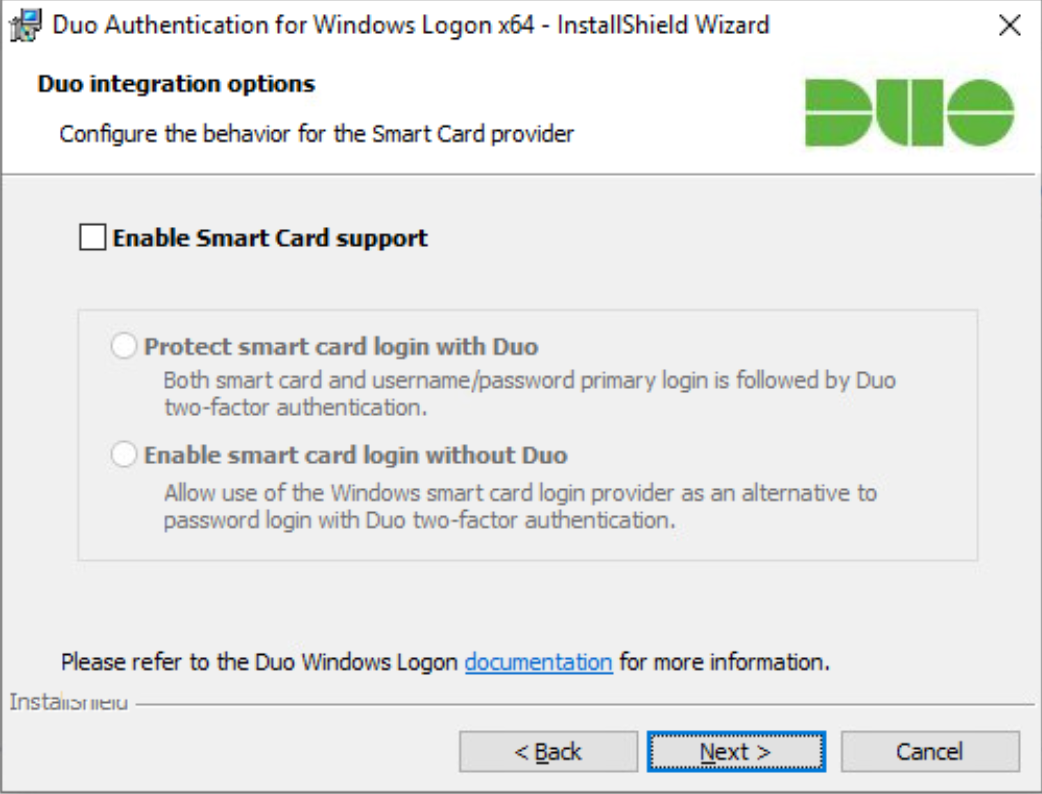
Click Next.
Leave Enable UAC Elevation Protection unchecked.
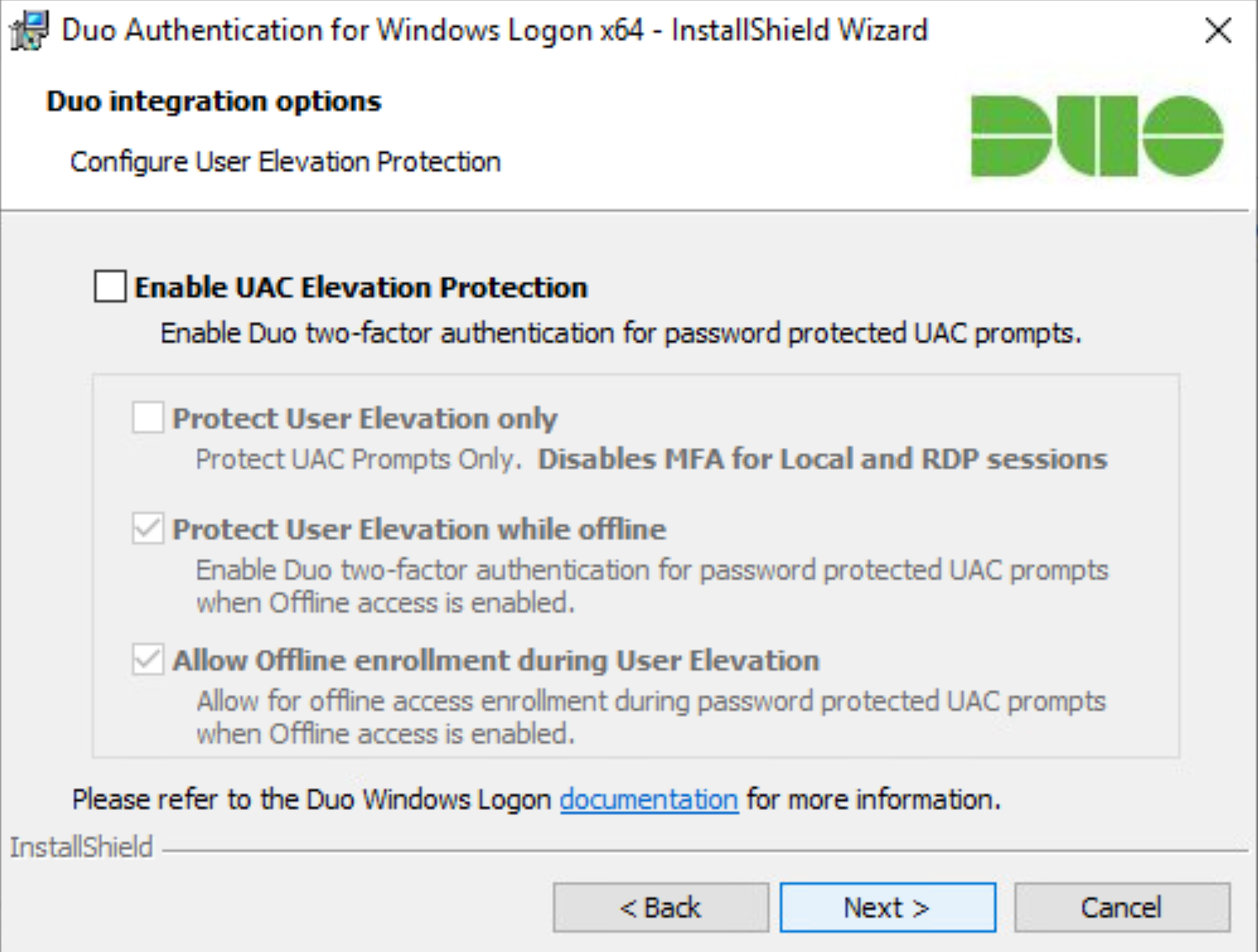
Click Next.
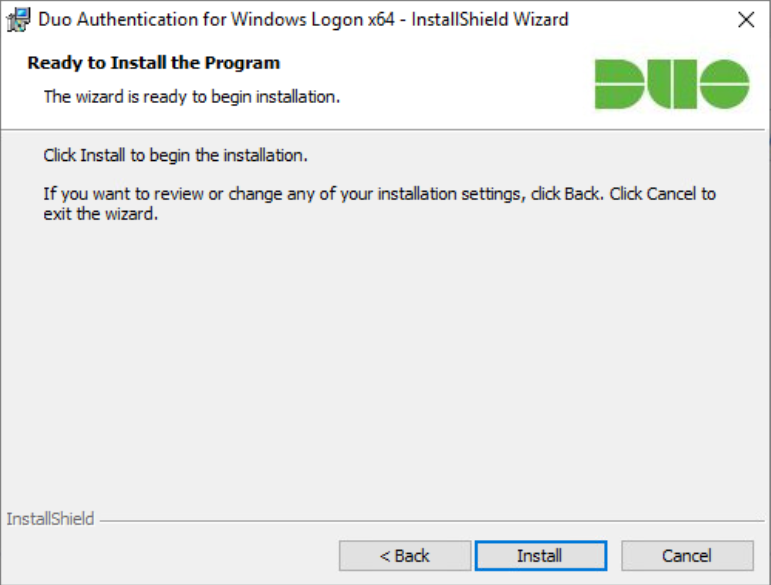
Click Install.
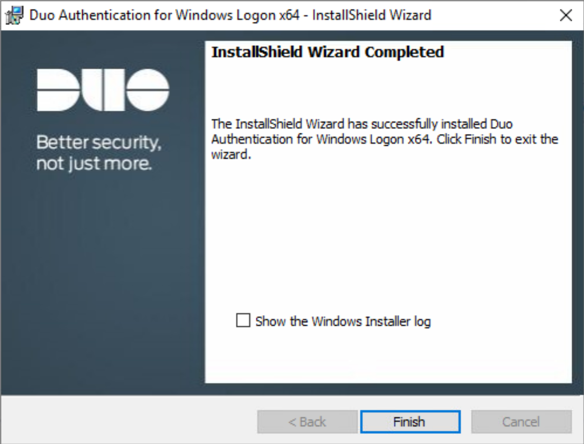
Click Finish.
Installation should now be complete. Users registered on the Duo Dashboard with a linked phone will be allowed access to the system.
2.7.2 Registering a Duo User
Login to the Duo Admin Dashboard.
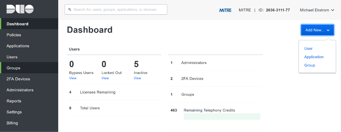
Click Add New > User from the drop-down menu on the right.
Enter a username for the user.
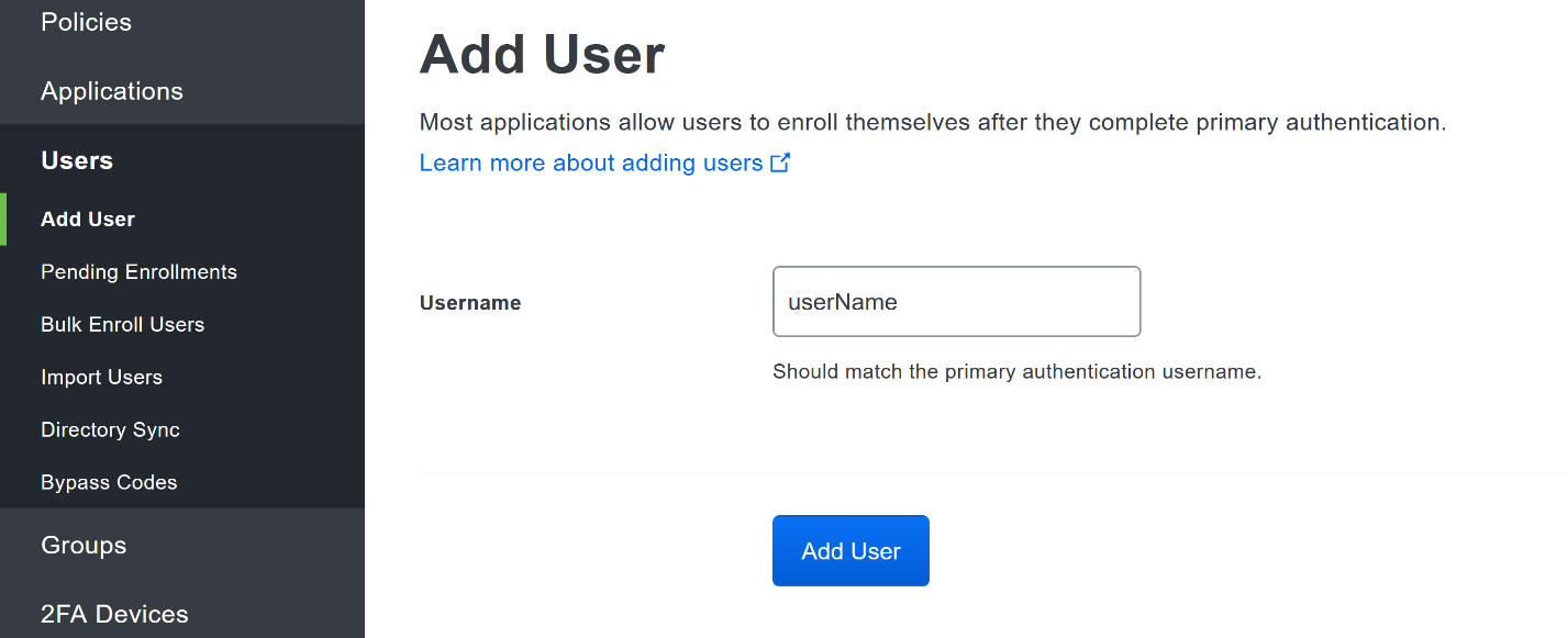
Click Add User.
This will lead you to that user’s information page, where additional information (full name, email, phone number) and Duo authenticators (phone numbers, 2 Factor Authentication (2FA) hardware tokens, WebAuthn, etc.) can be associated with that username. Note: A user will not be able to log into a Duo protected system unless the user is registered and has an authentication device associated with their username.
2.8 Dispel
Dispel is a network protection and user access tool that we used to provide a Virtual Desktop Infrastructure (VDI) capability. A typical deployment of Dispel is done in a largely managed fashion, with a specific deployment being tailored to a network setup. The deployment in the NCCoE laboratory may not be the best setup for any given network. The NCCoE deployment was done on an Ubuntu host with Wide-Area Network (WAN) and Local-Area Network (LAN) interfaces, placing the device in-line between the enterprise systems and the external network.
2.8.1 Installation
Deploy an Ubuntu machine with the provided specifications, ensuring that a provided ISO is attached to the device.
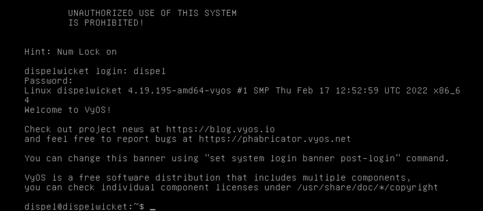
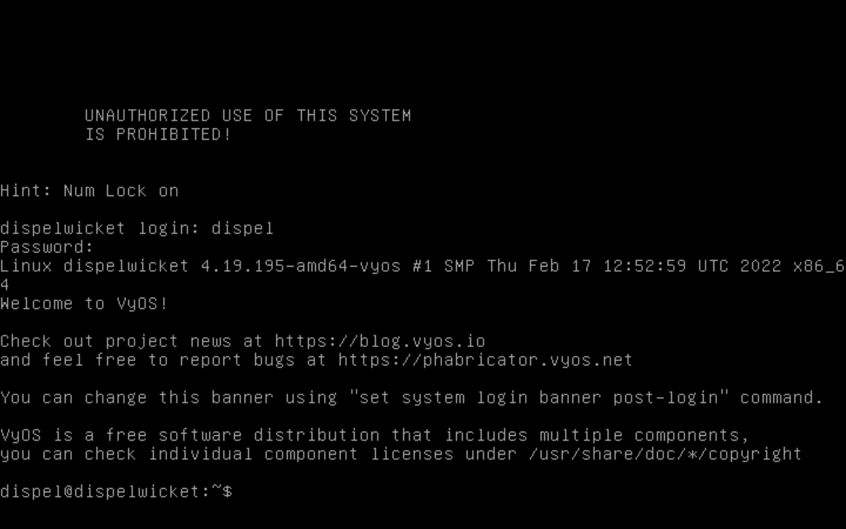
Login with username “dispel” and the password provided.
Begin the installation process
> install image
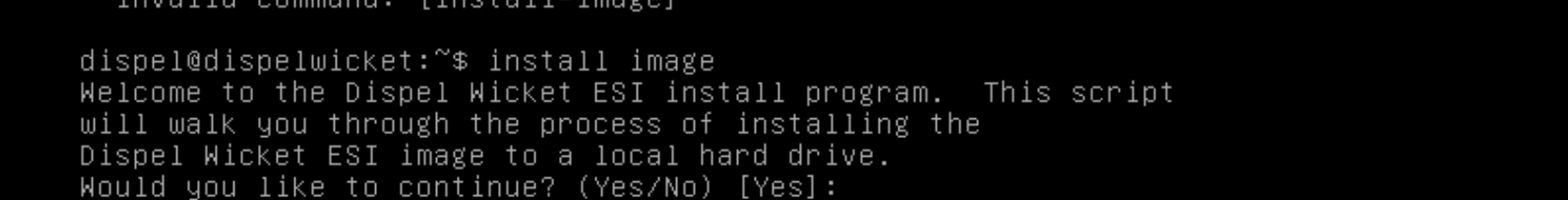
Press enter on the following three prompts, modifying any default options as desired.
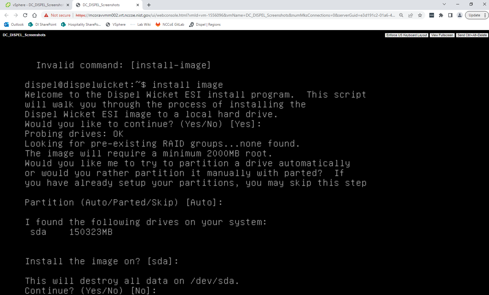
Type
yesbefore pressing enter to rewrite the current volume.
Press enter on the remaining prompts, modifying any default options as desired.
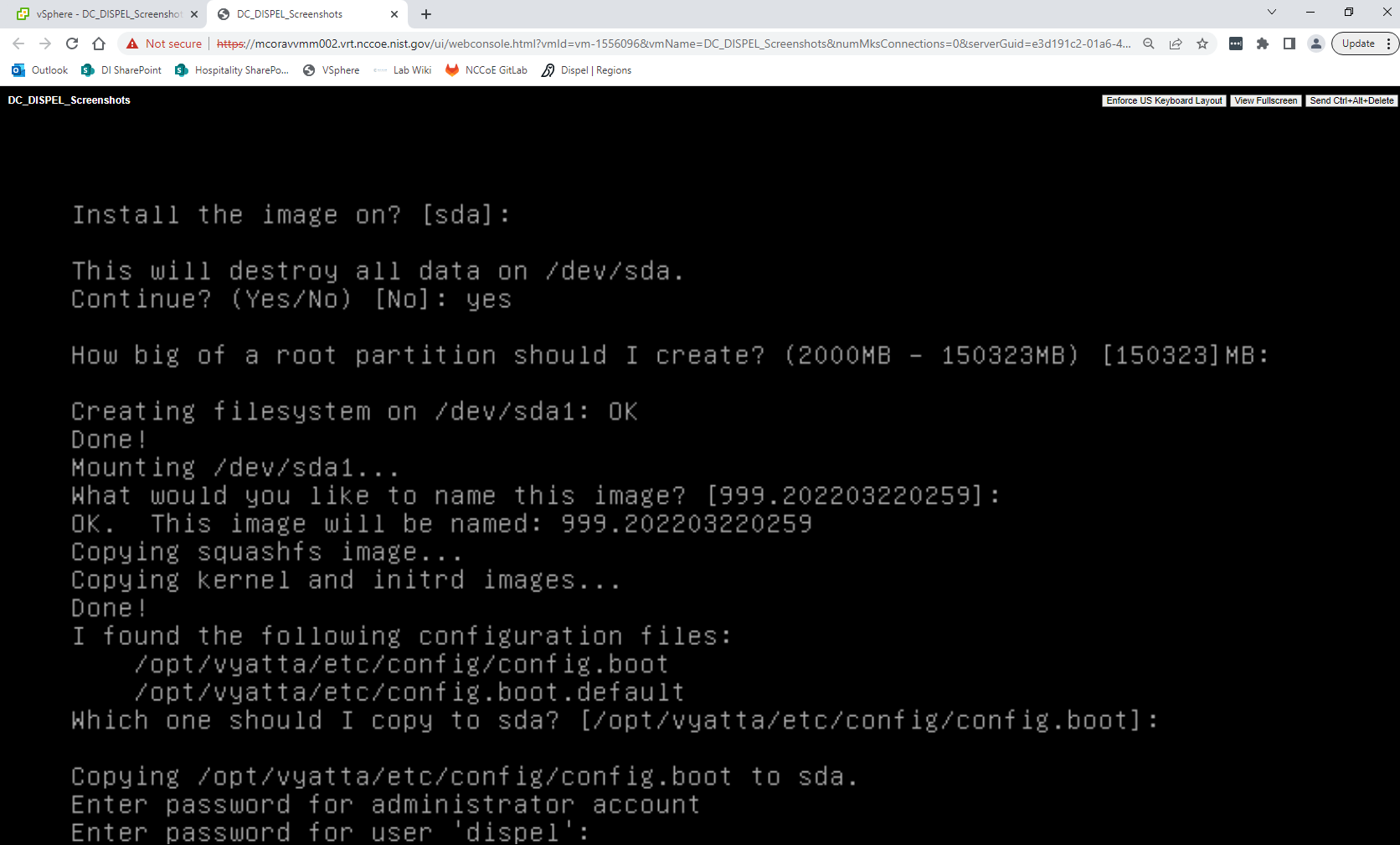
Enter and re-enter a new password for the user dispel
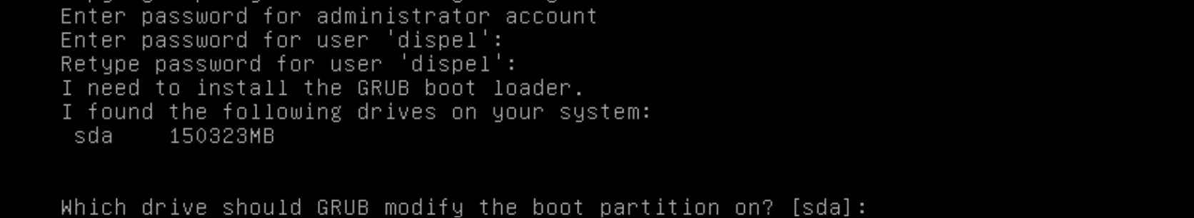
Press enter one final time to finish the installation
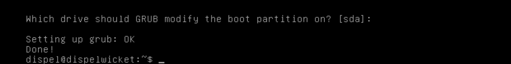
Power off the machine, remove the provided ISO, and power it back on.
Log in with the user “dispel” and the new password set in step 9.
Type in the command
> ifconfig \| grep inet. Verify the output to make sure it matches the desired network configuration. If not, see the next section.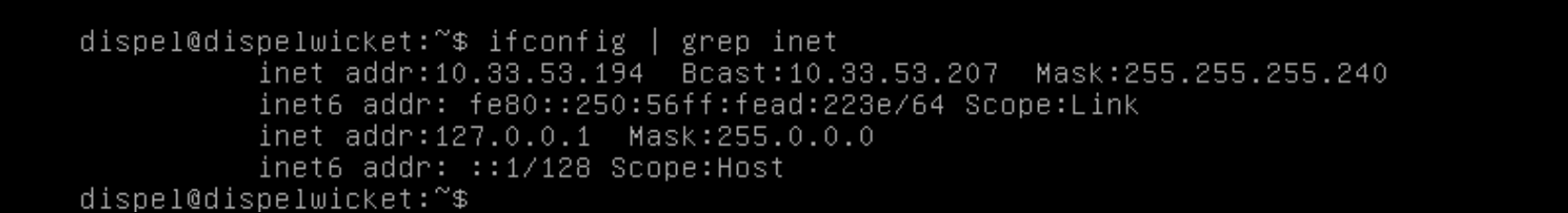
2.8.2 Configuring IP Addresses
Login to the device with the user “dispel”.
Type in the command
> configure.
Type in the command
> del interfaces ethernet eth0, or whichever interface you are currently modifying.
Type in the command
> set interfaces ethernet eth0address followed by the desired IP address in CIDR notation, modifying for the desired interface as appropriate.
Type in the command
> commit.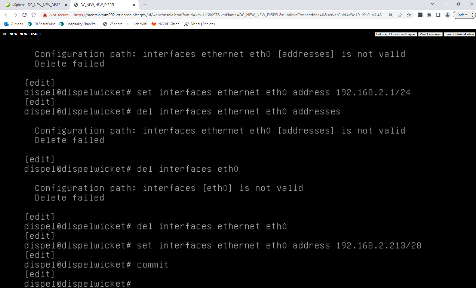
Type in the command
> save.
Type in the command
> exit.
2.8.3 Configuring Network
The following instructions are to modify a Dispel wicket device to forward traffic to a different routing device. This may be desirable for some network setups.
Type in the command
> configureto the Dispel wicket device after logging in.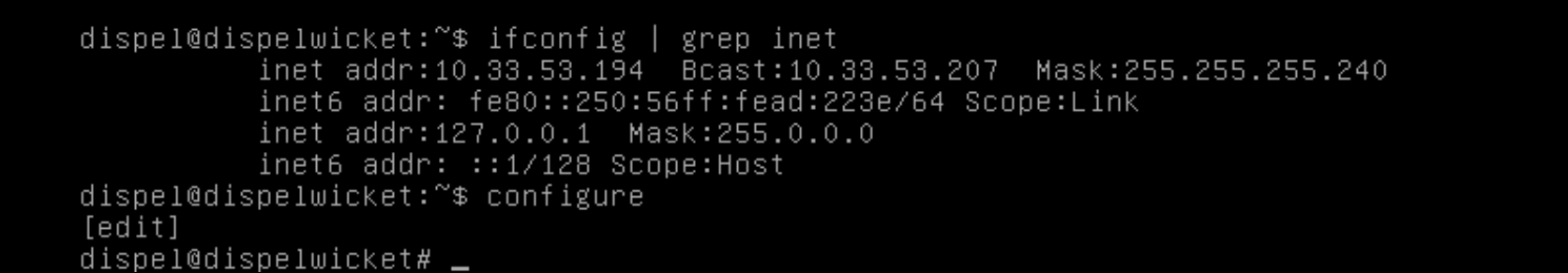
Type in the command
> set protocols static route 0.0.0/0 next-hopfollowed by the IP address of the router you wish to forward to.
Type in the command
> commit.
Type in the command
> save.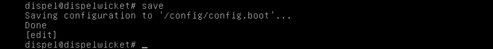
Type in the command
> exit.On the designated router or firewall, ensure User Datagram Protocol (UDP) is allowed from the Dispel device on the provided port. For the NCCoE deployment, port 1194 was utilized. A target destination for the traffic will be provided by Dispel.
Modify the IP addresses of the south-side network interface to properly align with your network. See the “Configuring IP Addresses” section above.
2.8.4 Adding a Device
On the workstation in question, ensure that ping and RDP are accessible, including allowing such connections through a local firewall.
Authenticate to the Dispel webpage with the provided credentials.
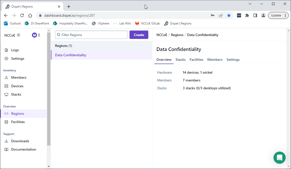
Click on the Devices page on the sidebar and click Create.
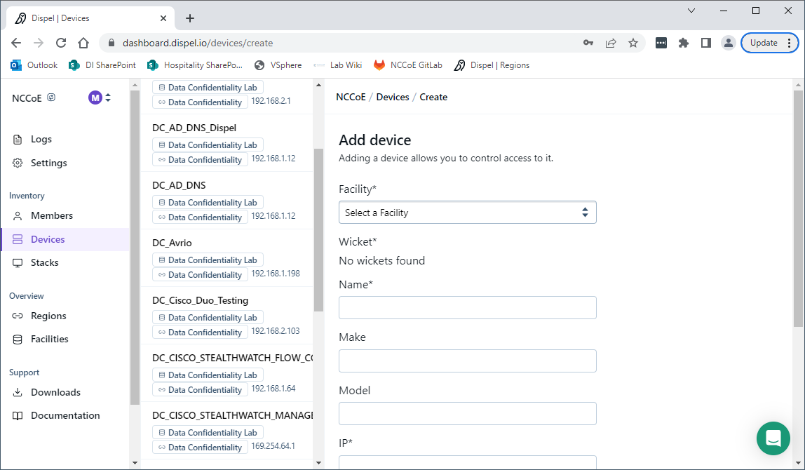
Under the Add Device window, fill out all fields, including Facility, Wicket, Name, Make, Model, IP, and Protocol.
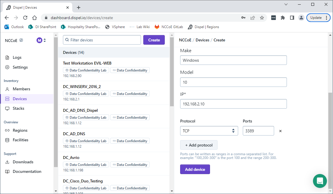
Click Add Device.
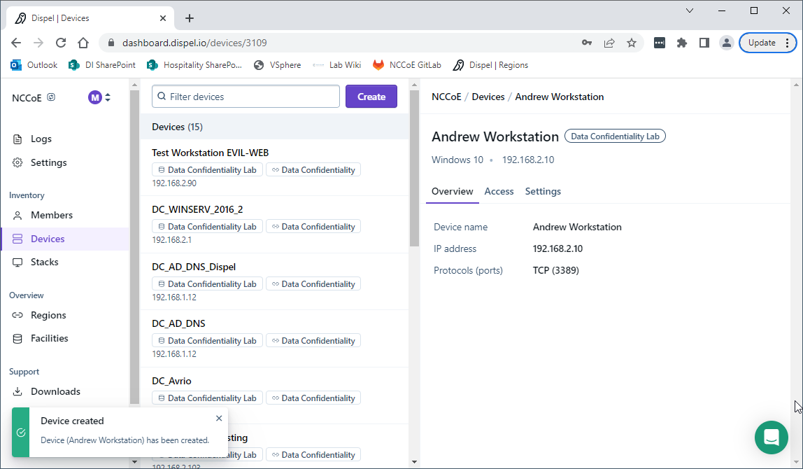
Under Access for that device, search for the user(s) that will have access to that device. Verify they have the correct access settings.
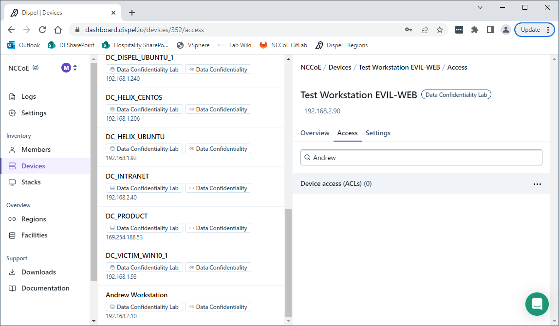
If a user is not already a member of the region, click Members in the sidebar and click Invite. Fill out relevant information for this individual and click Invite this Member.
2.9 Integration: FireEye Helix and Symantec SWG
In this integration the output of the web isolation tool, Symantec SWG, will be forwarded to our Security Information and Event Management (SIEM), FireEye Helix. In this guide, we will aim to forward most logs to our SIEM, which can collect, analyze, and report on these logs to better maintain awareness of our systems and provide a single interface for analyzing the health of the system. Logs from SWG will allow us to see statistics on the number of threats that have been blocked, as well as any administrative changes made to the SWG product.
2.9.1 Configure Fireye Helix to Collect Logs from Symantec SWG
Navigate to the Symantec dashboard, and login.
Navigate to Account Configuration by clicking the gear icon on the left sidebar.
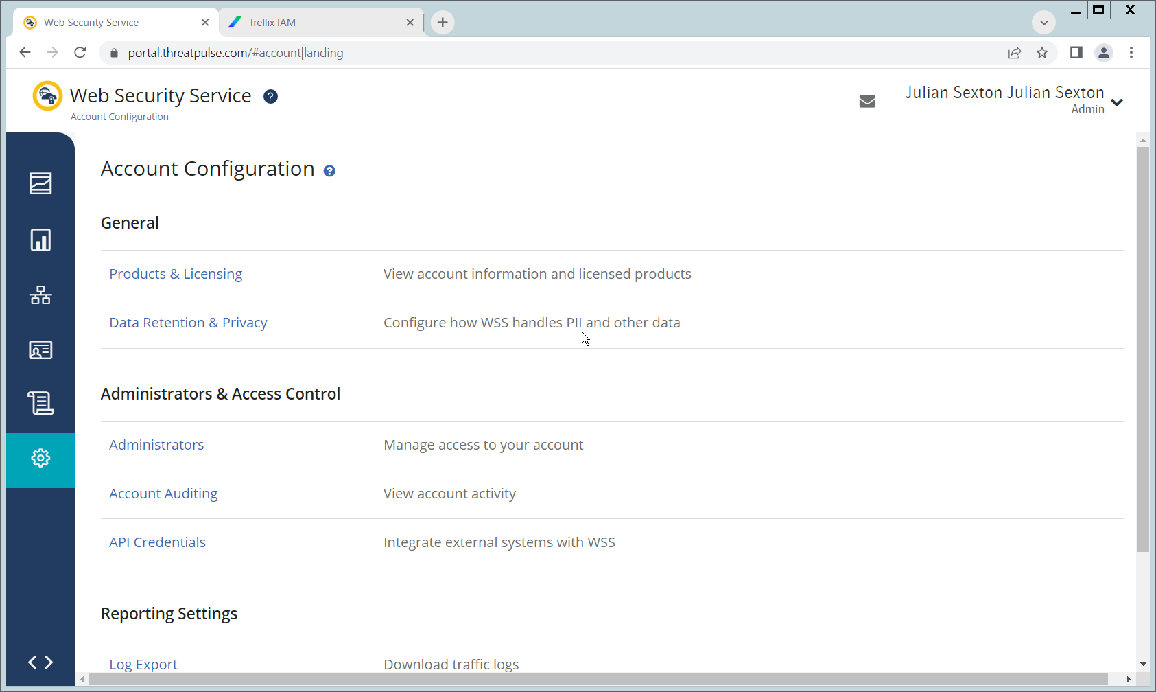
Click API Credentials.
Click Add.
Check the boxes next to Reporting Access Logs, Location Management, Audit Logs, Agent Config Management, and Egress IP.
Set an Expiration Date for the credential (1 year recommended).
Copy the Username and Password provided, as you will not be able to retrieve these once you create the credential.
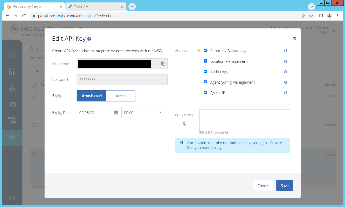
Click Save.
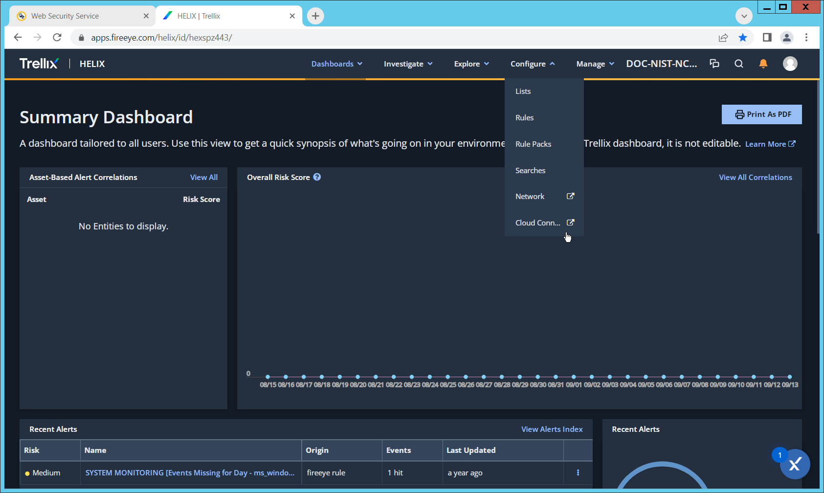
On the Helix Dashboard, click Configure > Cloud Connect.
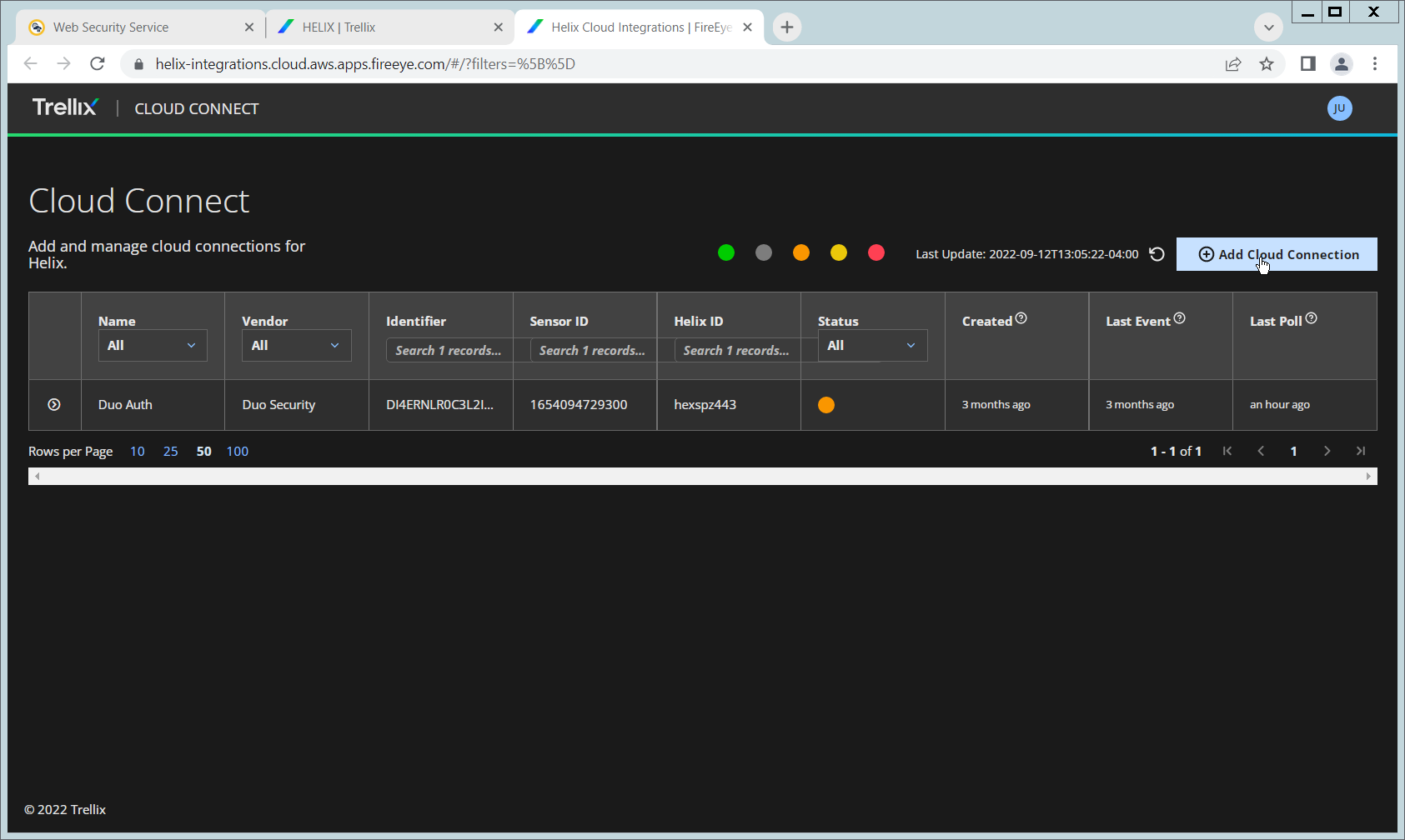
Click Add Cloud Connection.
Click the arrow next to Symantec Web Security Service.
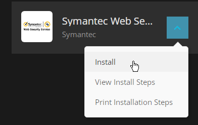
Click Install.
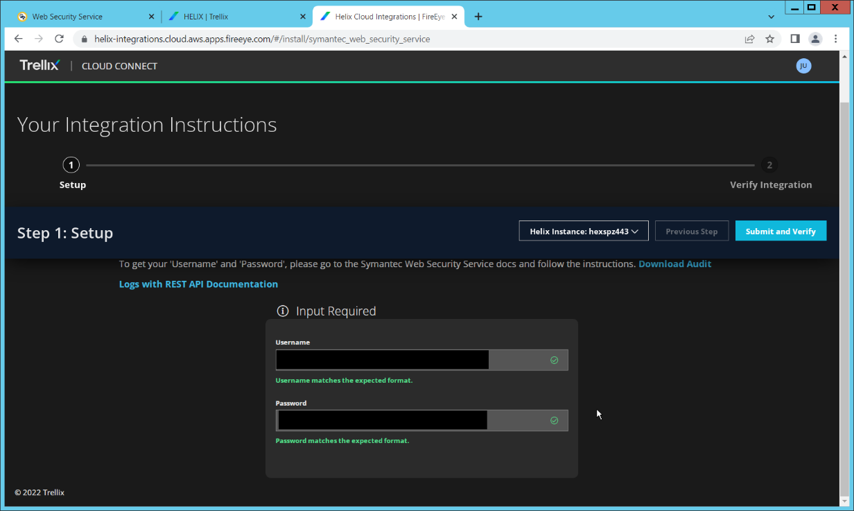
Enter the username and password from the credential created earlier.

Click Submit and Verify.
Click Back to Home. You will now be able to see events from Symantec SWG in Helix.
2.10 Integration: FireEye Helix and PKWARE PKProtect
In the following section, PKWARE PKProtect, which has been configured to identify and encrypt sensitive data, will be configured to forward these events to FireEye Helix. Logs from PKWARE PKProtect will allow us to monitor the use of encryption throughout the enterprise, and catch any suspicious decryptions that may indicate a breach. This section assumes the Helix Communications Broker has already been installed.
2.10.1 Configure the Helix Communications Broker
On the CentOS system with the Helix Communications Broker installed, run the following commands:
| > cd /opt/tap-nxlog
| > sudo ./setup.sh
Select Add Routes and press Enter.
Select bsd.
Select tcp.
Select the IP address of the network interface which should receive logs.
Enter 513 for the port.
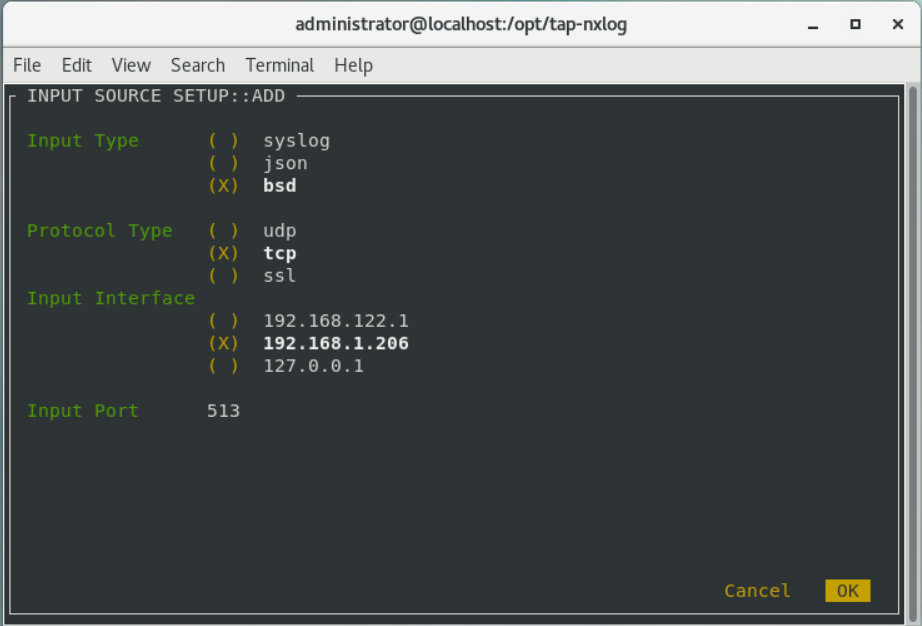
Select OK and press Enter.
Select OK and press Enter.
2.10.2 Configure PKWARE PKProtect to Forward Events
Navigate to the PKWARE PKProtect web portal.
Click the Basics link at the top of the page.
Scroll down to the Data Security Intelligence section.
Next to Dashboard Elasticsearch Target, click Internal.
Uncheck the box next to Use Internal Elasticsearch.
Uncheck the box next to Enable DSI in Dashboard.
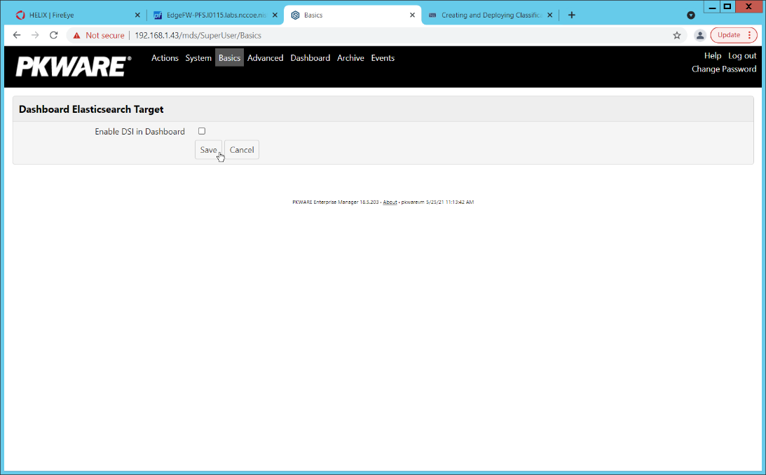
Click Save.
In the Data Security Intelligence section, click Internal next to Target.
Select Syslog TCP RFC-3164 for Target.
Enter the URL and port of the Helix Communications Broker that was just configured.
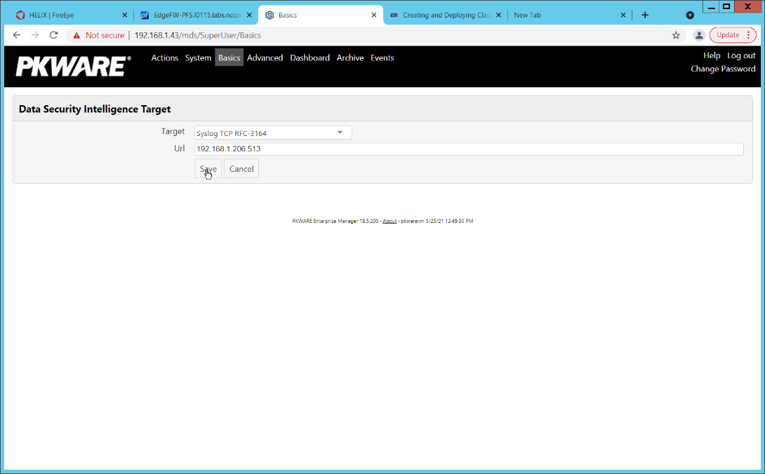
Click Save.
Verify that PKWARE logs now show up in Helix.
2.11 Integration: FireEye Helix and Cisco Duo
In this integration, FireEye Helix will be configured to collect logs from Cisco Duo. Cisco Duo is our multi-factor authentication mechanism and acts as source of information both for detecting breaches and for detecting insider threats. Information about a login, such as the username, time, location, are all useful in the event of a breach. Furthermore, they are useful as a baseline for user activity, which can be used as a comparison point for detecting unusual behavior.
2.11.1 Configure Fireye Helix to Collect Logs from Cisco Duo
On the Cisco Duo dashboard navigate to Applications.
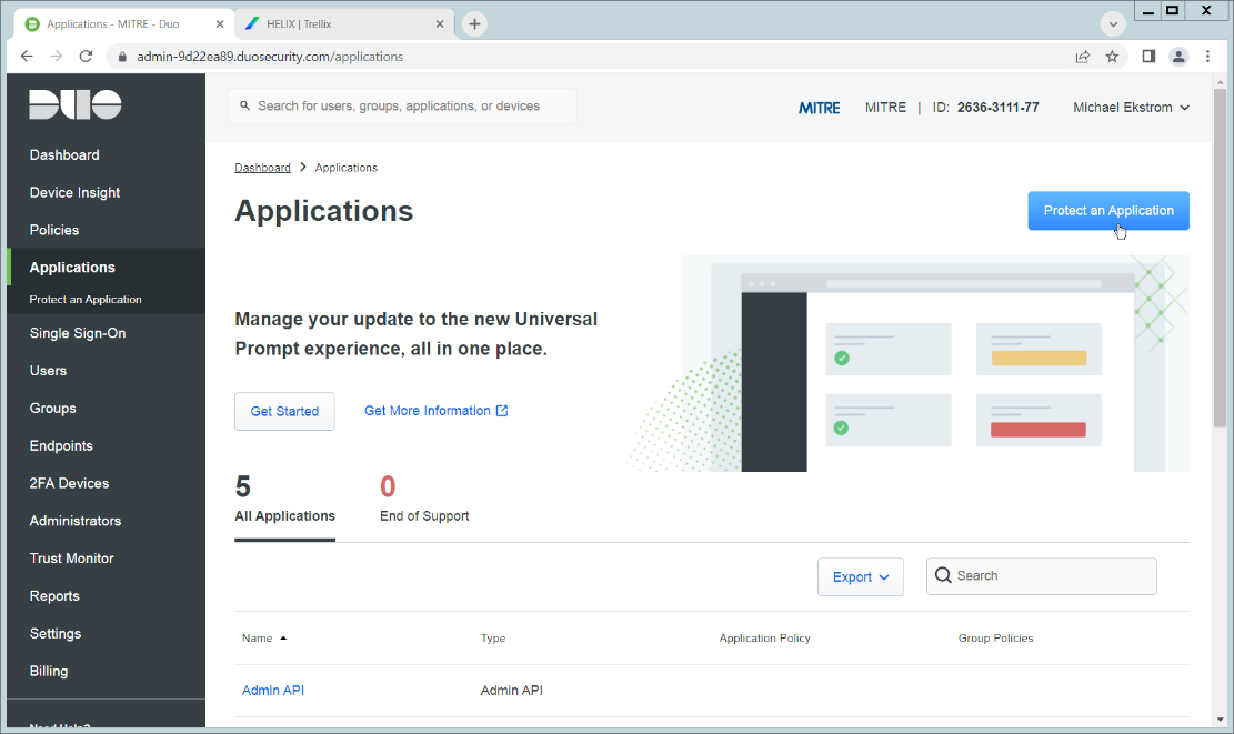
Click Protect an Application.
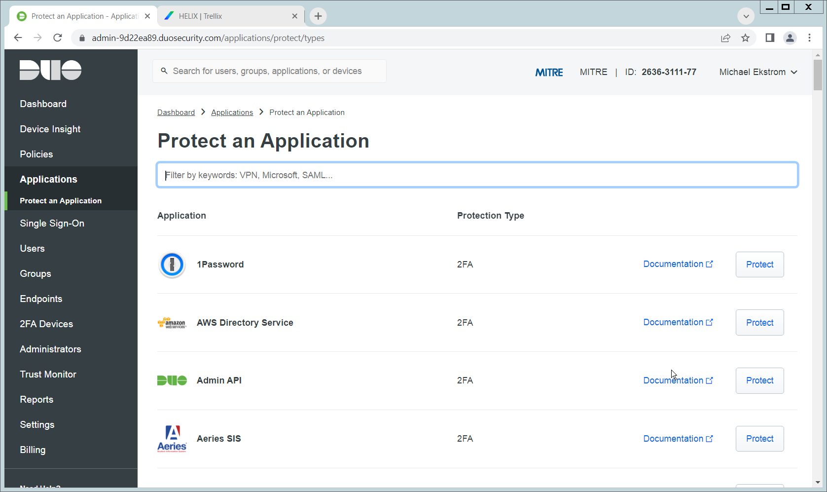
Click Admin API.
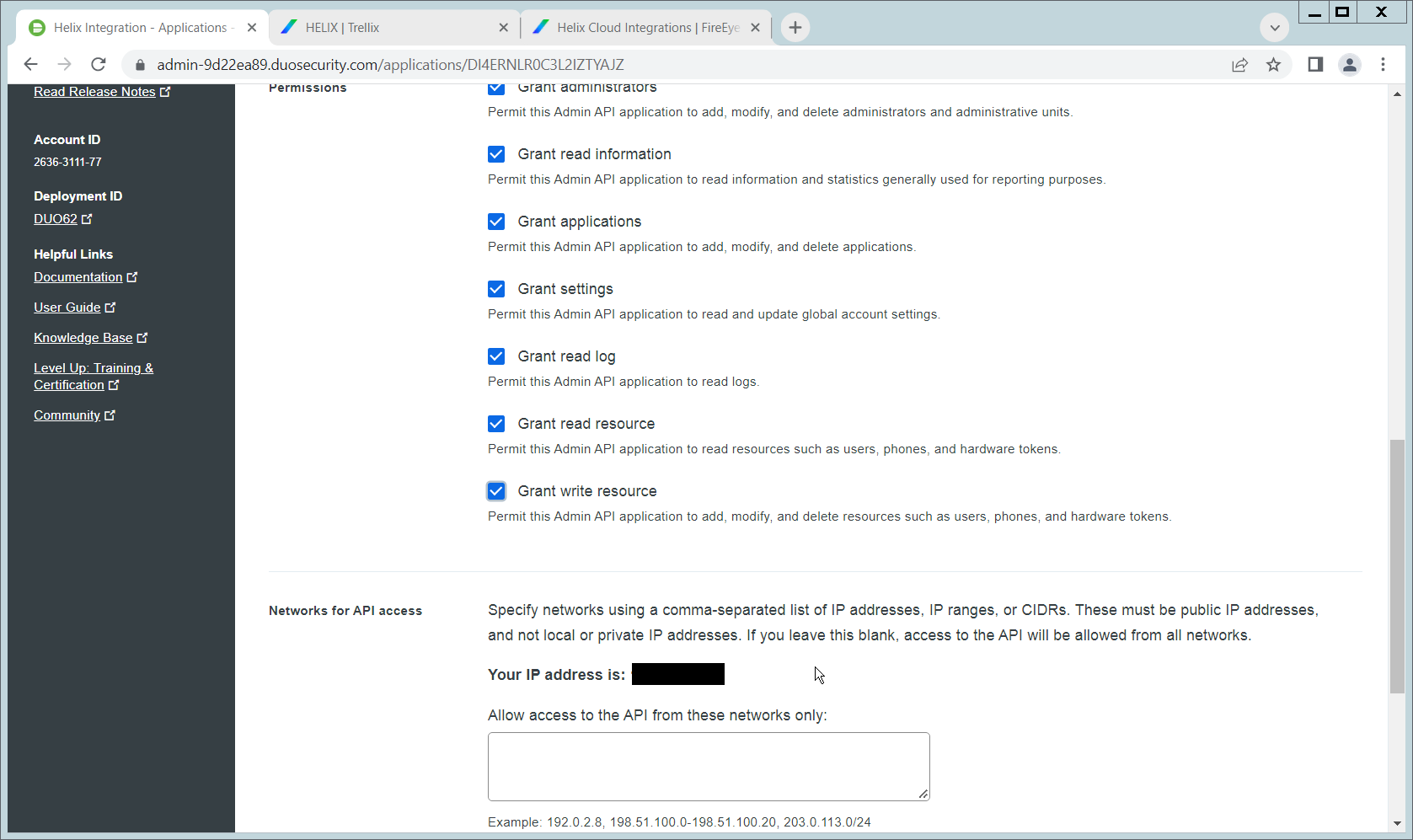
Scroll down and check the boxes next to Grant administrators, Grant read information, Grant applications, Grant settings, Grant read log, Grant read resource, and Grant write resource
Click Save.
Login to the Helix dashboard.
Navigate to Configure > Cloud Connect.
Click See Available Connections.
Type “Duo” in the Search box.
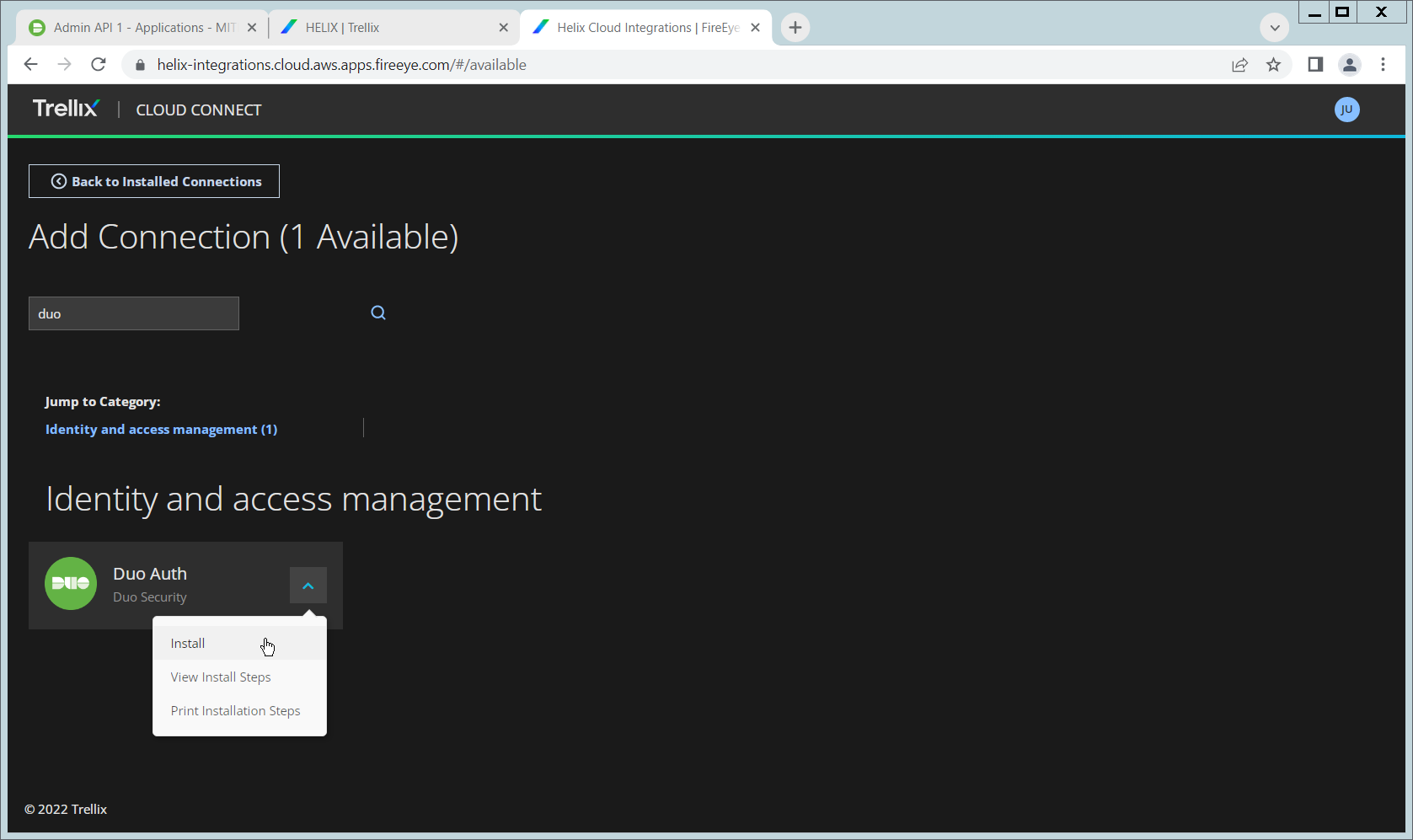
Click the Arrow next to the Cisco Duo integration and click Install.
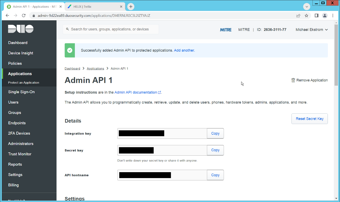
Copy the Integration Key, Secret Key, and API hostname (not including duosecurity.com) to the appropriate fields on the Helix Cloud Connect page.
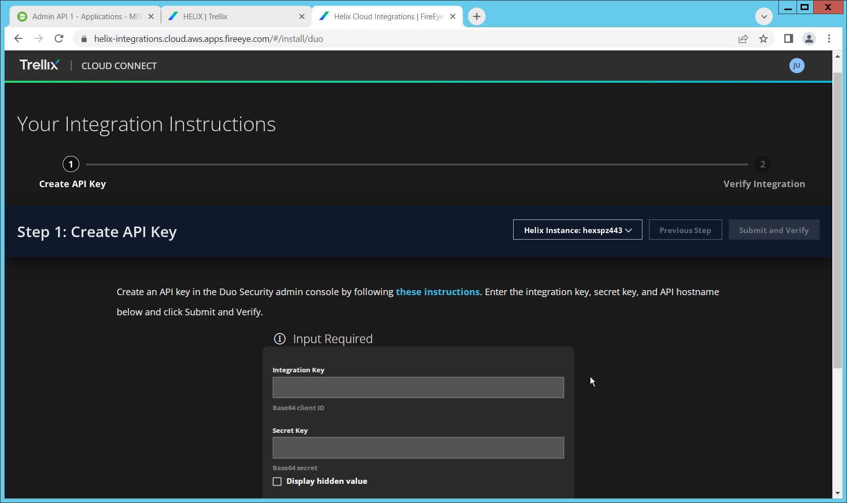
Click Submit and Verify.
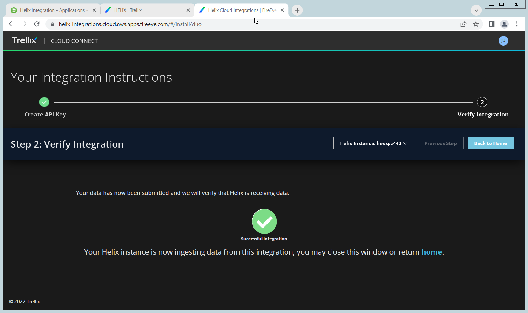
If successful, you should see a screen about the integration being successful.
2.12 Integration: FireEye Helix and QCOR ForceField
In this integration, we will configure the collection of logs from ForceField, our database encryption solution, into FireEye Helix. Detailed logs describing encryption and decryption are useful for determining how much of an enterprise is encrypted, and statistics and records in this area can prepare the organization for the event of a breach. For the purposes of this guide, we will assume ForceField is running on a Windows Server, and we would like to transfer files from this server to a Linux server. If you are using a Linux server for ForceField, you can skip to the configuration of rsyslog to forward logs directly to the Helix Comm Broker.
2.12.1 Configure an Secure File Transfer Protocol (SFTP) server on Windows
In this section, we will configure an SFTP server on the Windows system to allow for encrypted, automated download of Forcefield’s logs onto a Linux server. We have specifically elected not to use Windows Server Message Block (SMB) for this scenario because we would like to demonstrate an encrypted transfer of logs from Windows to Linux. We chose SFTP over FTPS because automation of File Transfer Protocol Secure (FTPS) would at some point require a plaintext password, while SFTP can default to the system’s Secure Shell (SSH) capabilities.
Once on Linux, rsyslog can be configured to use TLS for encrypted transfer according to the needs of the organization.
Download OpenSSH from here (https://github.com/PowerShell/Win32-OpenSSH/releases). During the creation of this guide, version V8.9.1.0p1-Beta was used.
Extract to
C:\Program Files\OpenSSH.In a Powershell window, navigate to the folder you extracted it to, and run the following command to install the server.
powershell.exe -ExecutionPolicy Bypass -File ./install-sshd.ps1
Run the following command to open the firewall port for OpenSSH.
Run New-NetFirewallRule -Name sshd -DisplayName 'OpenSSH SSH
Server' -Enabled True -Direction Inbound -Protocol TCP -Action
Allow -LocalPort 22 -Program
"C:\Windows\System32\OpenSSH\sshd.exe"
Open services.msc and start the OpenSSH SSH server.
Create a file called authorized_keys in C:\Users\<Your Username>\.ssh. If needed, create the .ssh folder (Windows will not allow you to create it by default – naming the folder .ssh. will allow you to bypass this restriction.)
Generate a key using ./ssh-keygen. Copy the contents of the generated public key (.pub file) into the authorized_keys file created earlier. The private key should be placed in the ~/.ssh folder on the Linux machine.
Right click the authorized_keys file and click Properties.
Click Disable Inheritance.
Select Convert inherited permissions into explicit permissions on this object.
Using the remove button, remove all accounts other than SYSTEM from the list. Ensure that the SYSTEM account has full control.
Under C:\ProgramData\ssh, open sshd_config.
Comment out these lines by adding ‘#’ characters before each line, like so:
#Match Group administrators

#   AuthorizedKeysFile\__PROGRAMDATA\_\_/ssh/administrators_authorized_keys
Add the following lines to the sshd_config file to ensure that RSA public key authentication is allowed.
PubkeyAuthentication yes

PubkeyAcceptedKeyTypes=+ssh-rsa
Add the directory C:\Program Files\OpenSSH to the system path – this is necessary so that the server can find the sftp-server.exe file.
Add the following lines to sshd_config file to configure the SFTP server.
ForceCommand internal-sftp

ChrootDirectory C:\GreenTec\ForceField\log
Alternatively, if it’s preferable to set the root directory somewhere else and move the log file, you can also do that. To edit the log file location, simply open C:\GreenTec\Forcefield\wfs.conf and change Logpath to a different directory, and update ChrootDirectory to point to that.
After doing this, you should be able to authenticate over SSH to the server. If the authentication fails, you can check the logs in Event Viewer on the server, under Applications and Services Logs > OpenSSH > Operational to see the reason for the failure.
2.12.2 Configure the Linux Machine to Download and Send Logs to the Helix Communications Broker
On the Linux server, we can use sftp to download the file. Ensure that you replace the username and hostname with the username and hostname of your actual SSH server.
sftp administrator@forcefield.dc.ipdrr:/ForceField.log /tmp/ForceField.log
For automation purposes, we can use cron jobs to automatically download this file at regular intervals. Use crontab to edit the list of cron jobs.
Crontab -e
Enter the interval and command for sftp in the crontab file. The following line will download the log file once an hour. Ensure that you replace the username and hostname with the username and hostname of your actual SSH server.
0 \* \* \* \* sftp administrator@forcefield.dc.ipdrr:/ForceField.log /tmp/ForceField.log
Next, we will use rsyslog to forward this log file to the Helix Comm Broker.
Open /etc/rsyslog.conf, and add the following line, using the IP and port of the Helix Comm Broker. (Note that putting a single ‘@’ symbol here indicates UDP. Use two, such as ‘@@’ for TCP.)
\*.\* @192.168.1.206:514
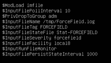
Create a file /etc/rsyslog.d/forcefield.conf and enter the following lines in it.
sudo nano /etc/rsyslog.d/forcefield.conf
$ModLoad imfile
$InputFilePollInterval 10
$PrivDropToGroup adm
$InputFileName /tmp/ForceField.log
$InputFileTag FORCEFIELD
$InputFileStateFile Stat-FORCEFIELD
$InputFileFacility local8
$InputRunFileMonitor
$InputFilePersistStateInterval 1000
Restart rsyslog.
sudo service rsyslog restart
2.13 Integration: FireEye Helix and Dispel
In this integration, we configure the collection of logs from Dispel, our network protection solution. Because Dispel controls access from users to enterprise systems, it is important to have an overview of its actions through log collection and reporting. Dispel personnel can perform this integration by simply providing them with the protocol, port, and IP address of the Helix Communications Broker and allowing them to configure it on the on-premise Dispel wicket.
2.14 Integration: Avrio SIFT and PKWARE PKProtect
When used together, SIFT and PKProtect can protect sensitive data accidentally dropped into public shares on the enterprise. In Section 2.6, we detail how to configure SIFT to detect sensitive data in a Windows Share and move it to a location designated for sensitive information. Now, we will demonstrate how to ensure that location is protected by PKProtect, which will automatically encrypt the data.
2.14.1 Configuring PKWARE PKProtect
Navigate to the PKProtect dashboard and login.
Navigate to Archive > Discovery.
Click Pattern – Dictionary.
Enter a name for these patterns in the Name field.
Enter keywords to match in the Keywords field.
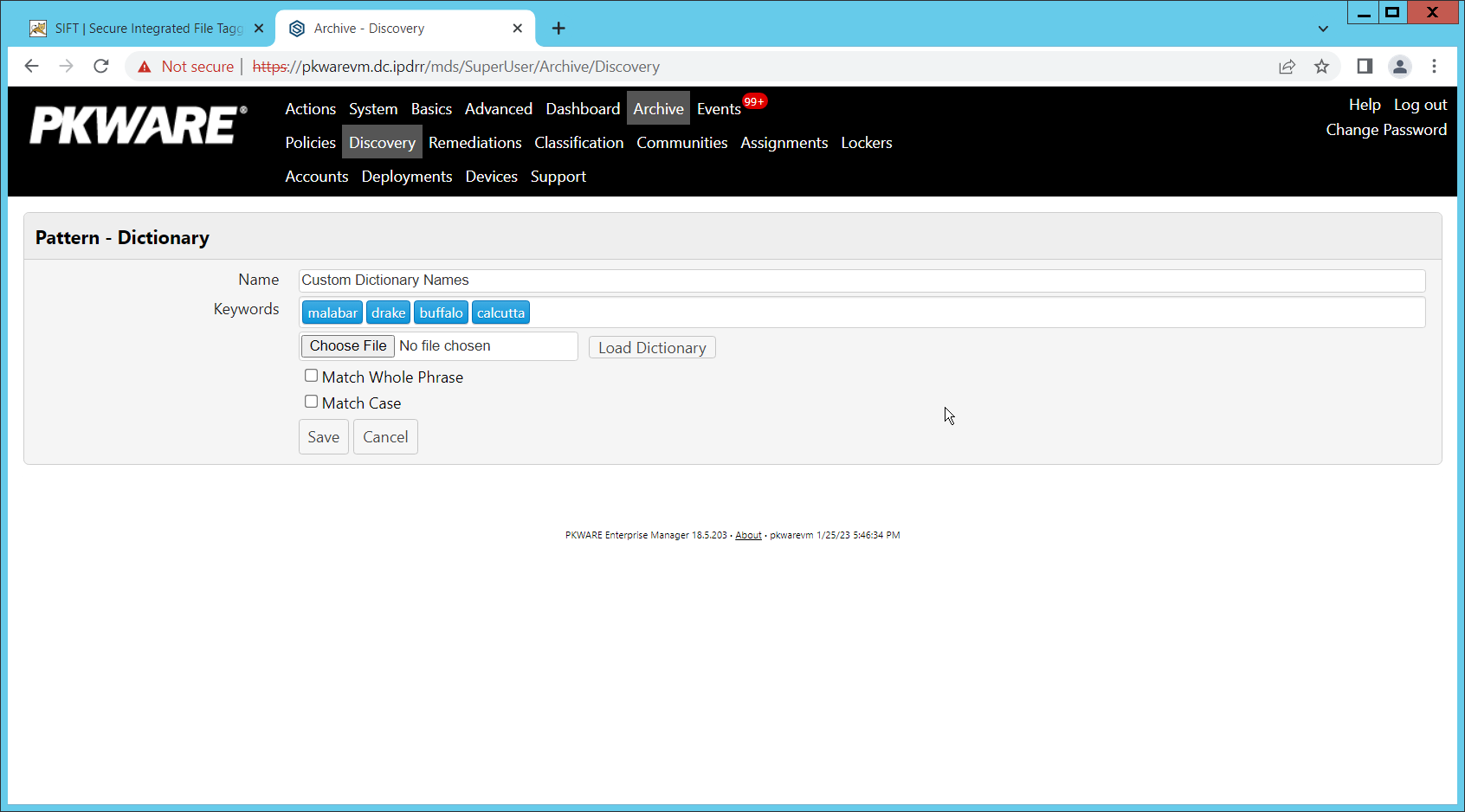
Click Save.
Click Add Discovery.
Under Pattern, select the name of the Pattern you just created.
For Threshold, enter the number of matches of this pattern needed to consider the file sensitive.
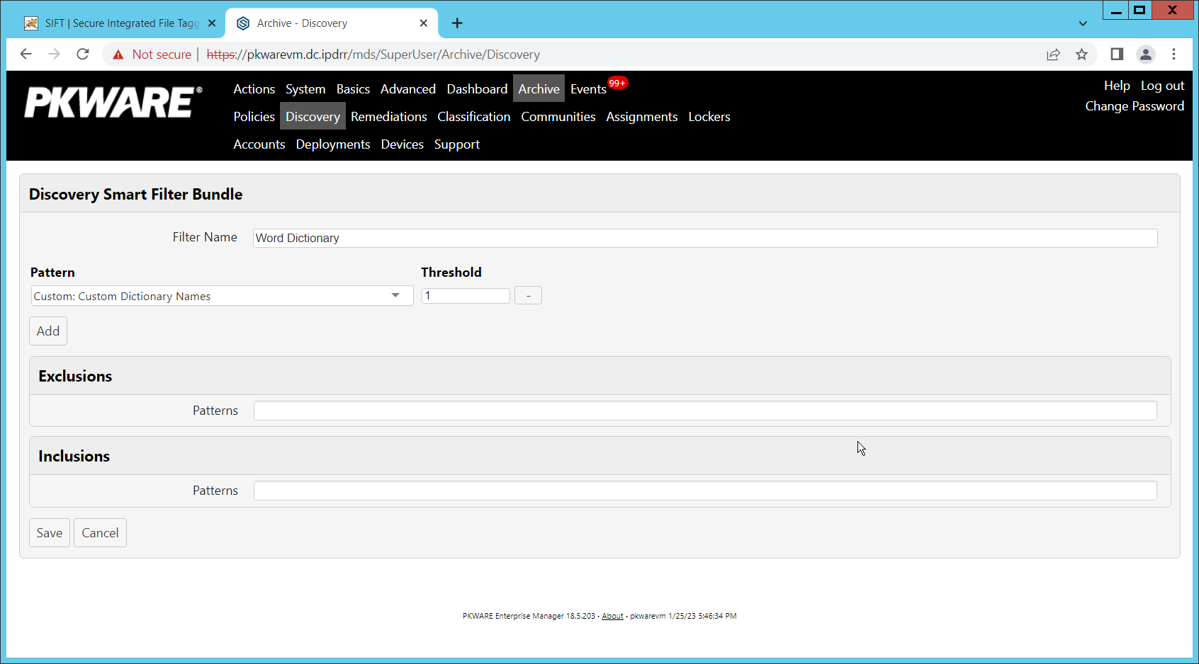
Click Save.
Navigate to Archive > Lockers.
Ensure that a PKWARE client is installed on the device which will be monitored for encryption. The device should show up in the list. If it doesn’t you can search for the device and select it from the list.
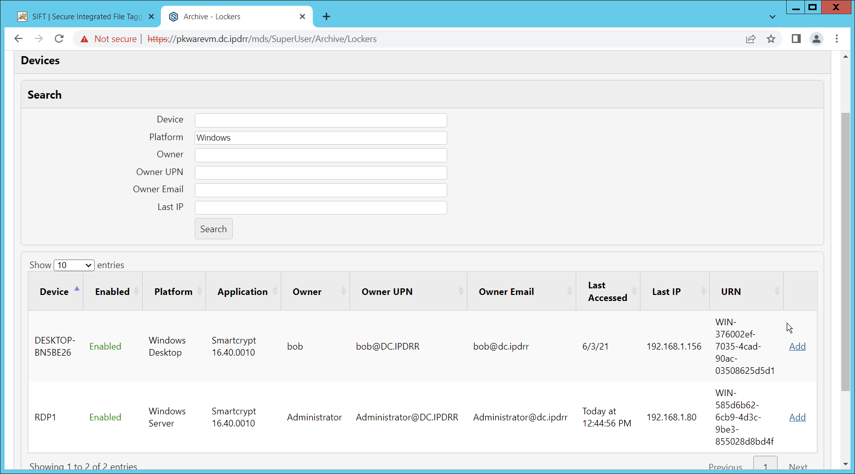
Click Add on the device you wish to add a locker for.
Enter a Name for the locker.
Enter the path to the protected folder.
Select AES 256 for the Algorithm.
Select the PKWARE Smartkey to use.
Check all the boxes next to Encryption Events.
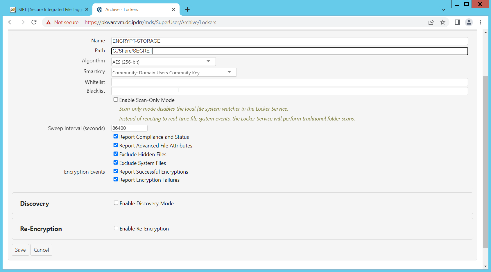
Check the box next to Enable Discovery Mode.
Add the relevant rules to the Smart Filter Bundles box.
Select Report and Encrypt for Remediation Action.
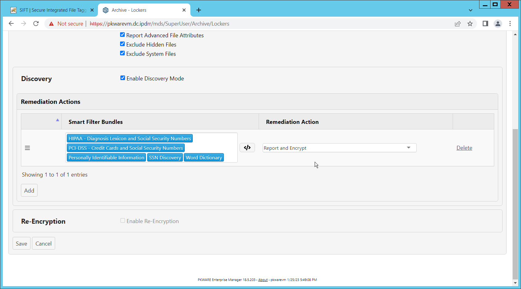
Click Save.
Now the folder on the device you selected will be monitored, and files which match the selected rules will be encrypted automatically.
2.15 Integration: Dispel and Cisco Duo
In this build, Dispel acts as an intermediary between the user and enterprise systems, by providing temporary remote desktops with access to enterprise systems. In this integration, we primarily installed Cisco Duo on the enterprise systems, to require multifactor authentication over RDP between Dispel’s temporary remote desktops and the enterprise systems.
In this particular integration, no extra work was required other than installing Cisco Duo (see Section 2.7) on systems to control remote desktop access between Dispel machines and the other machines. However, it is important for organizations to check that this integration works and is present, to ensure that multifactor authentication is being applied to users who are logging in remotely.