NIST SPECIAL PUBLICATION 1800-27C
Securing Property Management Systems
Volume C:
How-to Guides
William Newhouse
Information Technology Laboratory
National Institute of Standards and Technology
Michael Ekstrom
Jeff Finke
Marisa Harriston
The MITRE Corporation
McLean, Virginia
March 2021
FINAL
This publication is available free of charge from
https://doi.org/10.6028/NIST.SP.1800-27
This publication is available free of charge from
https://www.nccoe.nist.gov/projects/use-cases/securing-property-management-systems

DISCLAIMER
Certain commercial entities, equipment, products, or materials may be identified by name or company logo or other insignia in order to acknowledge their participation in this collaboration or to describe an experimental procedure or concept adequately. Such identification is not intended to imply special status or relationship with NIST or recommendation or endorsement by NIST or NCCoE; neither is it intended to imply that the entities, equipment, products, or materials are necessarily the best available for the purpose.
National Institute of Standards and Technology Special Publication 1800-27C, Natl. Inst. Stand. Technol. Spec. Publ. 1800-27C, 138 pages, March 2021, CODEN: NSPUE2
FEEDBACK
As a private-public partnership, we are always seeking feedback on our practice guides. We are particularly interested in seeing how businesses apply NCCoE reference designs in the real world. If you have implemented the reference design, or have questions about applying it in your environment, please email us at hospitality-nccoe@nist.gov.
All comments are subject to release under the Freedom of Information Act.
NATIONAL CYBERSECURITY CENTER OF EXCELLENCE
The National Cybersecurity Center of Excellence (NCCoE), a part of the National Institute of Standards and Technology (NIST), is a collaborative hub where industry organizations, government agencies, and academic institutions work together to address businesses’ most pressing cybersecurity issues. This public-private partnership enables the creation of practical cybersecurity solutions for specific industries, as well as for broad, cross-sector technology challenges. Through consortia under Cooperative Research and Development Agreements (CRADAs), including technology partners—from Fortune 50 market leaders to smaller companies specializing in information technology security—the NCCoE applies standards and best practices to develop modular, adaptable example cybersecurity solutions using commercially available technology. The NCCoE documents these example solutions in the NIST Special Publication 1800 series, which maps capabilities to the NIST Cybersecurity Framework and details the steps needed for another entity to re-create the example solution. The NCCoE was established in 2012 by NIST in partnership with the State of Maryland and Montgomery County, Maryland.
NIST CYBERSECURITY PRACTICE GUIDES
NIST Cybersecurity Practice Guides (Special Publication 1800 series) target specific cybersecurity challenges in the public and private sectors. They are practical, user-friendly guides that facilitate the adoption of standards-based approaches to cybersecurity. They show members of the information security community how to implement example solutions that help them align with relevant standards and best practices, and provide users with the materials lists, configuration files, and other information they need to implement a similar approach.
The documents in this series describe example implementations of cybersecurity practices that businesses and other organizations may voluntarily adopt. These documents do not describe regulations or mandatory practices, nor do they carry statutory authority.
ABSTRACT
Hotels have become targets for malicious actors wishing to exfiltrate sensitive data, deliver malware, or profit from undetected fraud. Property management systems, which are central to hotel operations, present attractive attack surfaces. This example implementation strives to increase the cybersecurity of the property management system (PMS) and offer privacy protections for the data in the PMS. The objective of this guide was to build a standards-based example implementation that utilizes readily available commercial off-the-shelf components that enhance the security of a PMS.
The NCCoE at NIST built a PMS reference design in a laboratory to explore methods for improving the cybersecurity of a PMS. The scope of the PMS reference design included the PMS, a credit card payment platform, and an analogous ancillary hotel/PMS. In this example implementation, a physical access control system was used as the ancillary system.
The principal capabilities are to protect sensitive data, to enforce role-based access control, and to monitor for anomalies. The principal recommendations and best practices are implementing cybersecurity concepts such as zero trust architecture, moving target defense, tokenization of credit card data, and role-based authentication.
The PMS reference design outlined in this guide encourages hoteliers and similar stakeholders to adopt effective cybersecurity concepts by using standard components that are composed of open-source and commercially available components.
KEYWORDS
access control; hospitality cybersecurity; moving target defense; PCI-DSS; PMS; privacy; property management system; role-based authentication; tokenization; network security; zero trust architectures
ACKNOWLEDGMENTS
We are grateful to the following individuals for their generous contributions of expertise and time.
Name |
Organization |
|---|---|
Sapna George |
Cryptonite |
Hans Ismirnioglou |
Cryptonite |
Mike Simon |
Cryptonite |
Rich Walchuck |
Cryptonite |
Justin Yackoski |
Cryptonite |
Katherine Gronberg |
Forescout |
Timothy Jones |
Forescout |
Scott Morrison |
Forescout |
John Bell |
AjonTech LLC |
Shane Stephens |
Forescout |
Oscar Castiblanco |
Häfele |
Ryan Douglas |
Häfele |
Chuck Greenspan |
Häfele |
Sarah Riedl |
Häfele |
Harald Ruprecht |
Häfele |
Roy Wilson |
Häfele |
Kevin Garrett |
Remediant |
Paul Lanzi |
Remediant |
Nicole Guernsey |
StrongKey |
Pushkar Marathe |
StrongKey |
Arshad Noor |
StrongKey |
Bill Johnson |
TDi |
Pam Johnson |
TDi |
Kartikey Desai |
MITRE |
Eileen Division |
MITRE |
Karri Meldorf |
MITRE |
Paul Ward |
MITRE |
Trevon Williams |
MITRE |
The Technology Partners/Collaborators who participated in this build submitted their capabilities in response to a notice in the Federal Register. Respondents with relevant capabilities or product components were invited to sign a Cooperative Research and Development Agreement (CRADA) with NIST, allowing them to participate in a consortium to build this example solution. We worked with:
Technology Partner/Collaborator |
Build Involvement |
|---|---|
Cryptonite |
network protection appliance that provides additional layer of protection against cyber attacks |
Forescout |
visualizes the diverse types of devices connected to the network; enforces policy-based controls |
Häfele |
physical access control system that includes door locks, room-key encoding, and management |
Remediant |
real-time incident monitoring and detection, privilege escalation management, and reporting functions |
StrongKey |
payment solution appliance that secures credit card transactions and shrinks the payment card industry compliance enclave |
TDi |
access control platform that secures connections and provides control mechanisms to enterprise systems for authorized users and authorized devices; also monitors activity down to the keystroke |
List of Figures
Figure 1‑1a PMS Reference Design Detailed Architecture (1 of 2)
Figure 1‑1b PMS Reference Design Detailed Architecture (2 of 2)
Figure 2‑1 Network Protection Solution in the Reference Architecture
Figure 2‑2 Access Control Platform in the Reference Architecture
Figure 2‑3 Data Tokenization Appliance in the Reference Architecture
Figure 2‑4 Physical Access Control Server in the Reference Architecture
Figure 2‑5 Privileged Access Management System in the Reference Architecture
Figure 2‑6 Wireless Network Management in the Reference Architecture
List of Tables
Table 1‑1 Architecture List of Components
Table 1‑2 Network Segment Details of the Hospitality Example Lab Build
Table 1‑3 Lab Network Host Record Information
Table 2‑1 Required Destination Groups for CryptoniteNXT Configuration
Table 2‑2 Required Source-Destination Mappings for CryptoniteNXT Configuration
1 Introduction
The following volume of this guide shows information technology (IT) professionals and security engineers how we implemented this example solution. We cover all of the products employed in this reference design. We do not re-create the product manufacturers’ documentation, which is presumed to be widely available. Rather, this volume shows how we incorporated the products together in our environment.
Note: These are not comprehensive tutorials. There are many possible service and security configurations for these products that are out of scope for this reference design.
1.1 Typographic Conventions
The following table presents typographic conventions used in this volume.
Typeface/Symbol |
Meaning |
Example |
|---|---|---|
Italics |
file names and path names; references to documents that are not hyperlinks; new terms; and placeholders |
For language use and style guidance, see the NCCoE Style Guide. |
Bold |
names of menus, options, command buttons, and fields |
Choose File > Edit. |
Monospace |
command-line input, onscreen computer output, sample code examples, and status codes |
|
blue text |
link to other parts of the document, a web URL, or an email address |
All publications from NIST’s NCCoE are available at https://www.nccoe.nist.gov. |
1.2 Practice Guide Structure
This National Institute of Standards and Technology (NIST) Cybersecurity Practice Guide demonstrates a standards-based reference design and provides readers of this guide with the information they need if they choose to replicate the property management system (PMS) reference design. This reference design is modular and can be deployed in whole or in part.
This guide contains three volumes:
NIST SP 1800-27A: Executive Summary
NIST SP 1800-27B: Approach, Architecture, and Security Characteristics–what we built and why
NIST SP 1800-27C: How-To Guides–instructions for building the example solution (you are here)
Depending on your role in your organization, you might use this guide in different ways:
Business decision makers, including chief security and technology officers, will be interested in the Executive Summary, NIST SP 1800-27A, which describes the following topics:
challenges that enterprises face in making a PMS more secure
example solution built at the NCCoE
benefits of adopting the example solution
Technology or security program managers who are concerned with how to identify, understand, assess, and mitigate risk will be interested in NIST SP 1800-27B, which describes what we did and why. The following sections will be of particular interest:
Section 3.4, Risk Assessment, describes the risk analysis we performed.
Section 3.4.3, Cybersecurity Control Map, maps the security characteristics of this example solution to cybersecurity standards and best practices.
Section 6.2, Privacy Protections of the Reference Design, describes how we used the NIST Privacy Framework Subcategories. You might share the Executive Summary, NIST SP 1800-27A, with your leadership team members to help them understand the importance of adopting standards-based PMS cybersecurity.
IT professionals who want to implement an approach like this will find this whole practice guide useful. You can use this How-To portion of the guide, NIST SP 1800-27C, to replicate all or parts of the build created in our lab. This How-To portion of the guide provides specific product installation, configuration, and integration instructions for implementing the example solution. We do not re-create the product manufacturers’ documentation, which is generally widely available. Rather, we show how we incorporated the products together in our environment to create an example solution.
This guide assumes that IT professionals have experience implementing security products within the enterprise. While we have used a suite of commercial products to address this challenge, this guide does not endorse these particular products. Your organization can adopt this solution or one that adheres to these guidelines in whole, or you can use this guide as a starting point for tailoring and implementing parts of a more secure PMS. Your organization’s security experts should identify the products that will best integrate with your existing tools and IT system infrastructure. We hope that you will seek products that are congruent with applicable standards and best practices. Section 1.3.2, Architectural Overview, lists the products that we used and maps them to the cybersecurity controls provided by this reference solution.
Acronyms used in figures and tables are in the appendix List of Acronyms.
1.3 PMS Reference Design Overview
The NCCoE at NIST built an example laboratory environment, known hereafter as the PMS reference design, to explore options available to secure a PMS used by hotels and other organizations in the hospitality sector.
1.3.1 Usage Scenarios
Securing a PMS requires implementing strong security measures in not only the PMS but also the components that logically and physically communicate with it. These components include an access control platform, network protection solutions for enterprise and wireless networks, data tokenization, and privileged access management (PAM). The example implementation fulfills several use cases to demonstrate needed functionality of a hotel enterprise, including utilizing secure communication and tokenization during PMS transactions, creating a room key in a protected manner, and allowing only approved connections to the PMS.
The NCCoE worked with members of the NCCoE Hospitality Community of Interest to develop a set of use case scenarios to help design and test the PMS reference design. For a detailed description of the PMS reference design’s architecture and the use cases, see Section 4 in Volume B.
1.3.2 Architectural Overview
The Securing Property Management Systems reference design is shown in detail in Figure 1‑1a and Figure 1‑1b. These figures show the technologies used in the PMS reference design. The architecture displays the authentication mechanisms, protected network zones, privilege management, and hospitality enterprise functionality.
The implementation enforces that only authorized network communications are allowed to and from the PMS. Three access levels are allowed with the PMS in this build. Unprivileged users, such as guests, get limited access, e.g., the public-facing web pages for the PMS, and internet access. Privileged enterprise users, such as front desk employees, get elevated access to the reservation process. For this build, this is accomplished via a dedicated administrative web page, but this solution will differ based on the existing PMS configuration of the adopting enterprise. Finally, the access control platform controls any system-level access to administer the PMS server.
In addition to these privilege protections, we used technologies for secure authentication, secure storage, and secure Wi-Fi.
We constructed the example implementation on the NCCoE’s VMware vSphere virtualization operating environment. A limited number of tools and technologies used in this build employed physical components. We used internet access to connect to remote off-site components, while we installed software components as virtual servers within the vSphere environment. The physical components were connected to the virtual servers through a layer 2 switch. The technology providers used in this build offer physical and virtual deployments of their products. Hospitality PMS implementations will vary, and the implementation decisions made in this build between virtual and physical will not necessarily align with every hospitality organization’s policies and designs.
The PMS reference design uses the components listed in Table 1‑1 and shown in Figure 1‑1a and Figure 1‑1b.
Table 1‑1 Architecture List of Components
Component |
Provider |
Installation Guidance |
|---|---|---|
network protection solution |
CryptoniteNXT |
|
access control platform |
TDi ConsoleWorks |
|
property management system |
Solidres |
|
data tokenization appliance |
StrongKey |
|
physical access control system |
Häfele Dialock |
|
privileged access management |
Remediant SecureONE |
|
wireless network management |
Forescout CounterACT |
1.3.3 General Infrastructure Details and Requirements
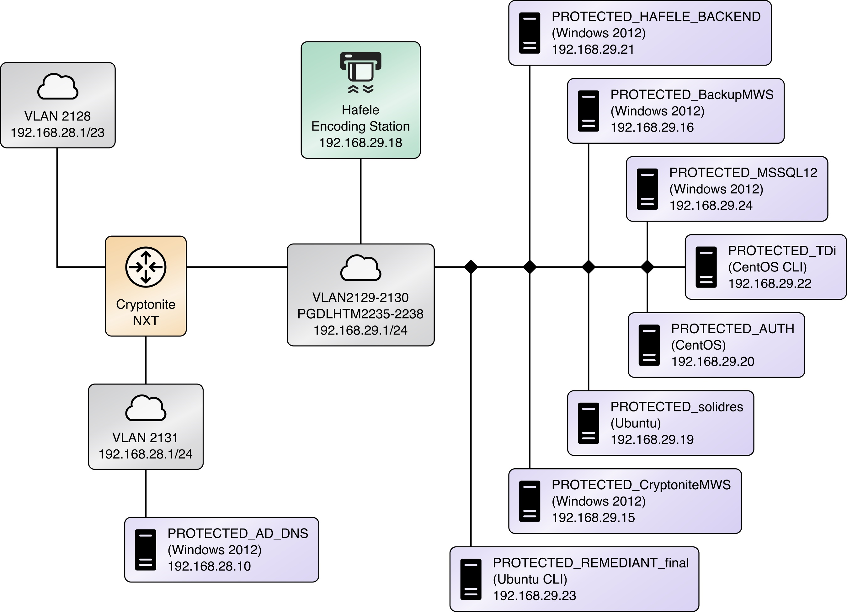
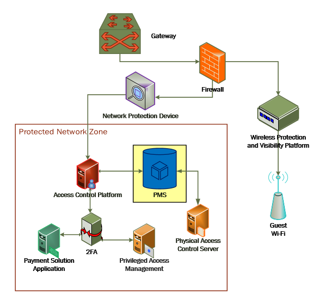
Figure 1-1a and Figure 1‑1b show the lab network architecture that supports the PMS reference design. The figures show the components, firewalls, and network design of the PMS reference design. We separated the figures into two figures to make them fit onto the page better with the VLAN (Virtual Local Area Network) 2128 device as the connector between the two figures. Figure 1-1a has the VLAN 2128 component in the upper right, and Figure 1‑1b shows it in the upper left. The installation and configuration details for the key components shown in the figures is the focus of this volume of the guide.
Figure 1‑1a PMS Reference Design Detailed Architecture (1 of 2)
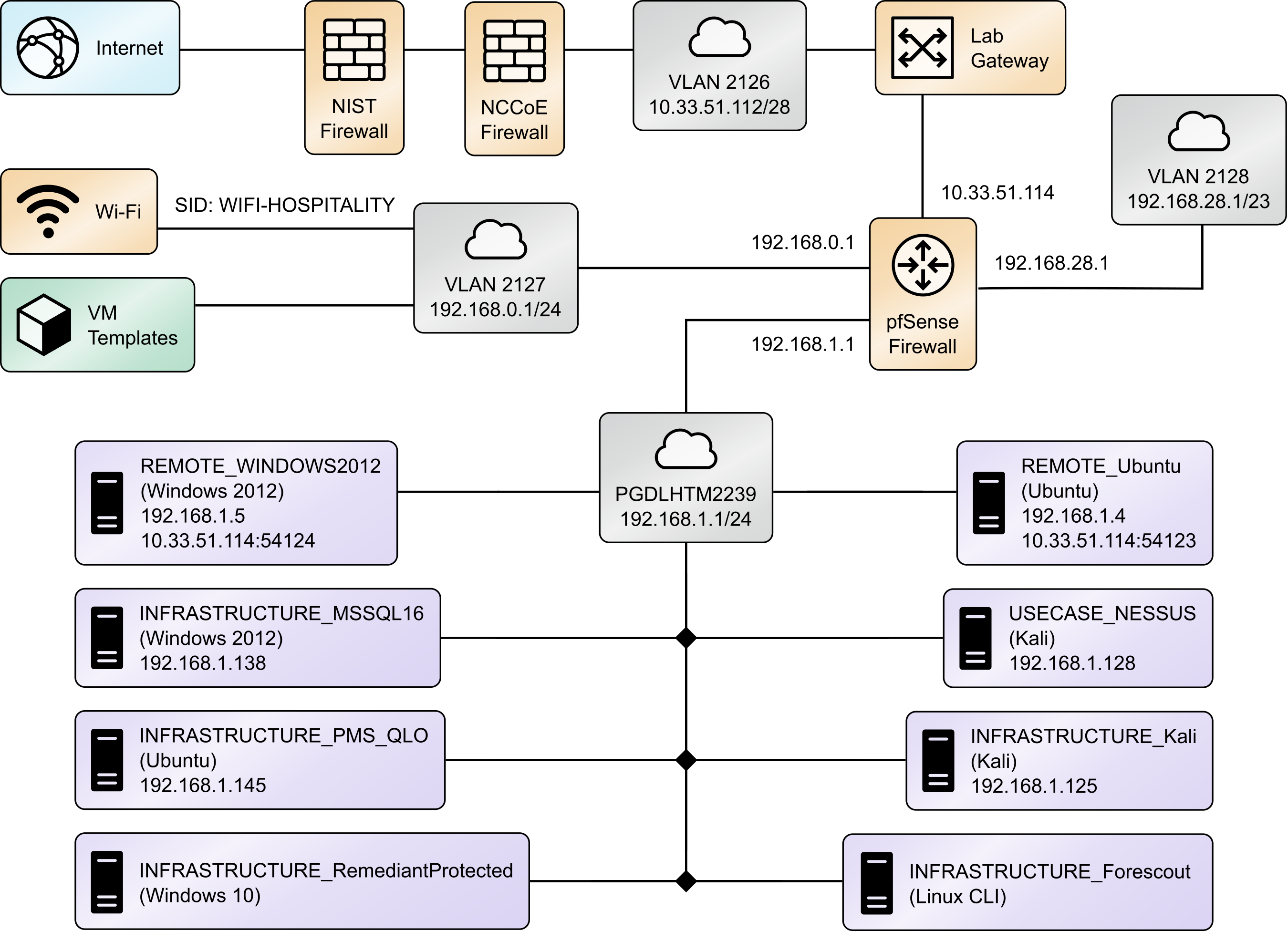
Figure 1‑1b PMS Reference Design Detailed Architecture (2 of 2)
1.3.3.1 Network Segmentation and Domain Name System (DNS)
Table 1-2 lists the hospitality example lab build’s network internet protocol (IP) address range for the PMS reference design. These network addresses were used in the example implementation builds, and each organization will configure IP addresses to reflect actual network architectures when deployed.
Table 1‑2 Network Segment Details of the Hospitality Example Lab Build
Network |
PMS Reference Design Segments |
|---|---|
192.168.0.0/24 |
hotel guest and employee Wi-Fi |
192.168.1.0/24 |
network demilitarized zone and Wi-Fi security enforcement |
192.168.28.0/23 |
back-end hotel infrastructure secure zone |
In the PMS reference design, DNS was configured as shown in Table 1-3, showing host names, fully qualified domain names (FQDNs), and IP addresses to facilitate data communication among the components. The domain for the PMS reference design is hotel.nccoe. Table entries marked with an asterisk are located within the CryptoniteNXT secured zone and do not require a static address. Figure 1-1a and Figure 1-1b show the architecture details with IP addresses.
Table 1‑3 Lab Network Host Record Information
Host Name |
FQDN |
IP Address |
|---|---|---|
win-hotel |
win-hotel.hotel.nccoe |
192.168.28.10 |
Forescout |
forescout.hotel.nccoe |
192.168.1.43 |
Tdi |
tdi.hotel.nccoe |
192.168.29.22* |
Remediantso |
remediantso.hotel.nccoe |
192.168.29.23* |
hafelees |
hafelees.hotel.nccoe |
192.168.29.18* |
hafele |
hafele.hotel.nccoe |
192.168.29.39* |
solidres |
solidres.hotel.nccoe |
192.168.28.194* |
admin-solidres |
admin-solidres.hotel.nccoe |
192.168.29.50* |
cryptonitews |
cryptonitemws.hotel.nccoe |
192.168.29.49* |
front-desk |
front-desk.hotel.nccoe |
192.168.29.42* |
mail.hotel.nccoe |
192.168.29.46* |
The network adapter configuration for the DNS server is as follows:
Network Configuration (Interface 1)
IPv4 Manual
IPv6 Disable
IP Address: 192.168.28.10
Gateway: 192.168.28.3
Netmask: 255.255.255.0
DNS Name Servers: 192.168.28.10
DNS-Search Domains: hotel.nccoe
2 How to Install and Configure
This section of the practice guide contains detailed instructions for installing and configuring all the products used to build an instance of the example implementation.
2.1 Network Protection Solution—CryptoniteNXT
This section of the guide provides installation and configuration guidance for the network protection solution, which ensures that only valid end points are allowed to connect to the network and the PMS, and that those end points use the network in an approved manner.
CryptoniteNXT is the network protection solution used in the example implementation.
When using a network protection solution such as CryptoniteNXT, we recommend installing and setting it up before installing other resources onto your network. This is because the CryptoniteNXT device serves as the router and switch for the enterprise network. However, apply the steps to secure the enterprise, as described in Section 2.1.8, to a component after the component has been separately installed and configured within the CryptoniteNXT environment.
The Administrator Control Center of CryptoniteNXT serves as the policy engine for zero trust architecture (ZTA).
2.1.1 Overview of Network Protection Solution
CryptoniteNXT is employed here as the network protection solution device and brings ZTA and moving target defense capabilities to the PMS reference design.
CryptoniteNXT is a network appliance installed as a physical device in the NCCoE hospitality lab. Installation instructions are included in the packaging that comes with the CryptoniteNXT device. The device is also available as a virtual appliance.
The CryptoniteNXT device requires that users authenticate using multifactor authentication and allows only validated connections within the implementation. The device applies a ZTA philosophy to its protected network zone. ZTA is an architectural approach that focuses on data protection and role-based authentication. Its goal is to eliminate unauthorized access to data, coupled with making the access control enforcement as granular as possible.
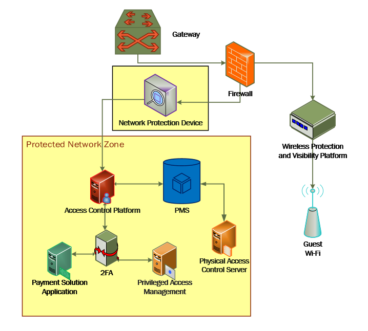
The moving target defense capability of the CryptoniteNXT device anonymizes IP addresses to prevent a malicious actor from mapping the enterprise network. The protected network zone controlled by CryptoniteNXT is shown in the yellow boxes in Figure 2‑1.
Figure 2‑1 Network Protection Solution in the Reference Architecture
2.1.2 Network Protection Solution–CryptoniteNXT–Requirements
The following subsections document the software, hardware, and network requirements for the network protection solution for version 2.9.1.
2.1.2.1 Hardware Requirements for the Network Protection Solution
CryptoniteNXT was deployed as a physical piece of hardware, provided by the vendor. If a virtual appliance is utilized, the appliance will require a 20-gigabyte (GB) hard drive, 4 GB of memory, and a virtual central processing unit (CPU). Additionally, Ethernet cables and a serial console cable are necessary for full setup and configuration.
2.1.2.2 Software Requirements for the Network Protection Solution
The CryptoniteNXT device is deployed with its own software requirements fulfilled. However, the first end points to connect to the device will require Java Runtime Environment to run the CryptoniteNXT Administration Control Center (ACC) graphical user interface (GUI) and a terminal emulator software, such as PuTTY, to fully install and configure the device.
2.1.2.3 Network Requirements for the Network Protection Solution
CryptoniteNXT requires the necessary physical and virtual hardware to allow all virtual end points to connect to it, fulfilling the purpose of a network switch and router. A connection is required to the upstream gateway that leads to the hotel’s wireless network, and to the internet. Furthermore, CryptoniteNXT relies on access to a dedicated local area network (LAN) or VLAN with the sole purpose of providing intercommunication between the CryptoniteNXT nodes.
2.1.3 Network Protection Solution—CryptoniteNXT–Installation
The majority of the installation and setup for the CryptoniteNXT device can be found in the CryptoniteNXT Unified Installation Guide. IP addresses and host names used in this solution are listed in Section 1.3.3 of this document. Properly configuring CryptoniteNXT to secure an enterprise requires creation and application of destination groups (also called access control policies) and source groups. A destination group defines the connections that are allowed to connect to a given end point. A source group defines the connections that an end point is allowed to make. Find more information in the CryptoniteNXT Administration Control Center (ACC) User Manual. Sections 2.1.4 and 2.1.5 have detailed instructions to create and apply a generic source and destination group.
The configuration procedure consists of the following steps:
Create a source group to govern what network connections can flow from an end point.
Create a destination group to govern what network connections can flow to an end point.
Apply a source group to a specific end point.
Apply a destination group to a specific end point.
Create and apply the necessary source and destination groups to correctly support the hotel enterprise, as detailed below.
2.1.4 Creating Source Groups
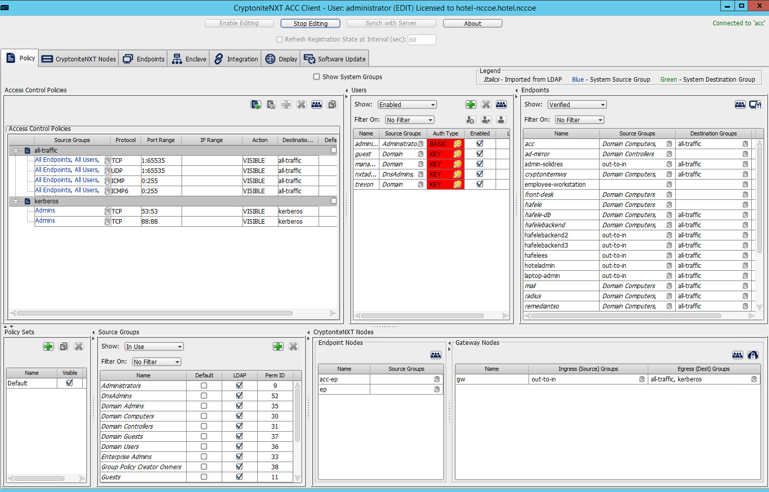
The following instructions assume that initial installation and configuration of the CryptoniteNXT device have been completed, as detailed in the CryptoniteNXT Unified Installation Guide. Once completed, open the CryptoniteNXT ACC GUI executable from a connected end point, and click the Policy tab to begin the following configuration.
In addition to providing guidance on creating a generic source group, the following instructions will allow authorized external traffic to flow through the CryptoniteNXT device.
In the Cryptonite Policy tab, click Enable Editing:
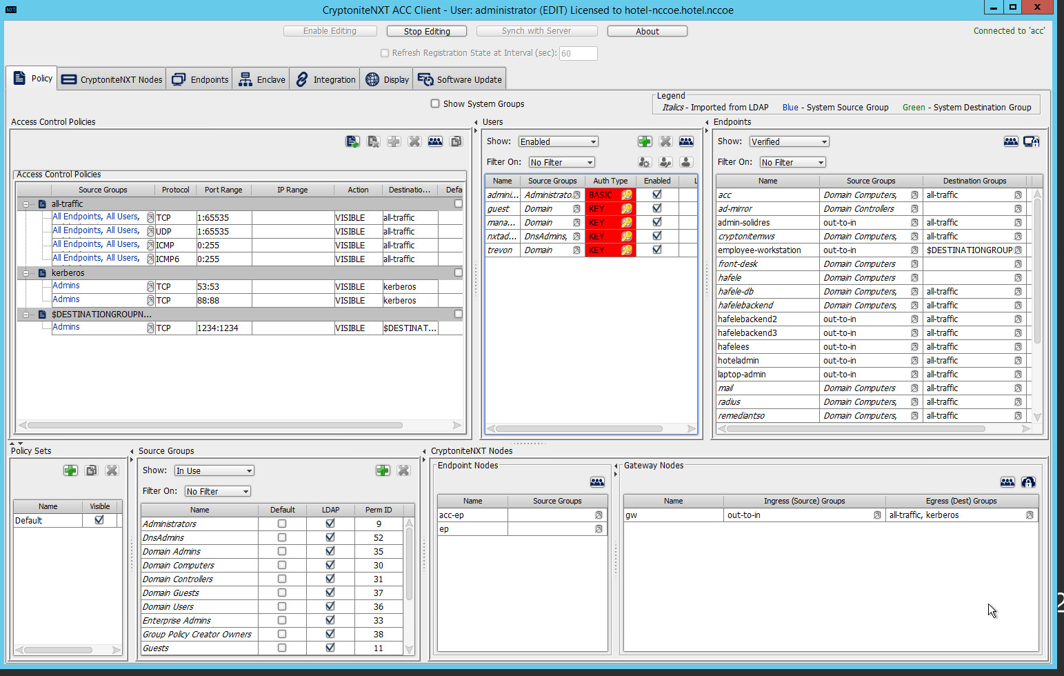
Under the Source Groups box, select the green plus button in the top right (hover text: New Source Group):
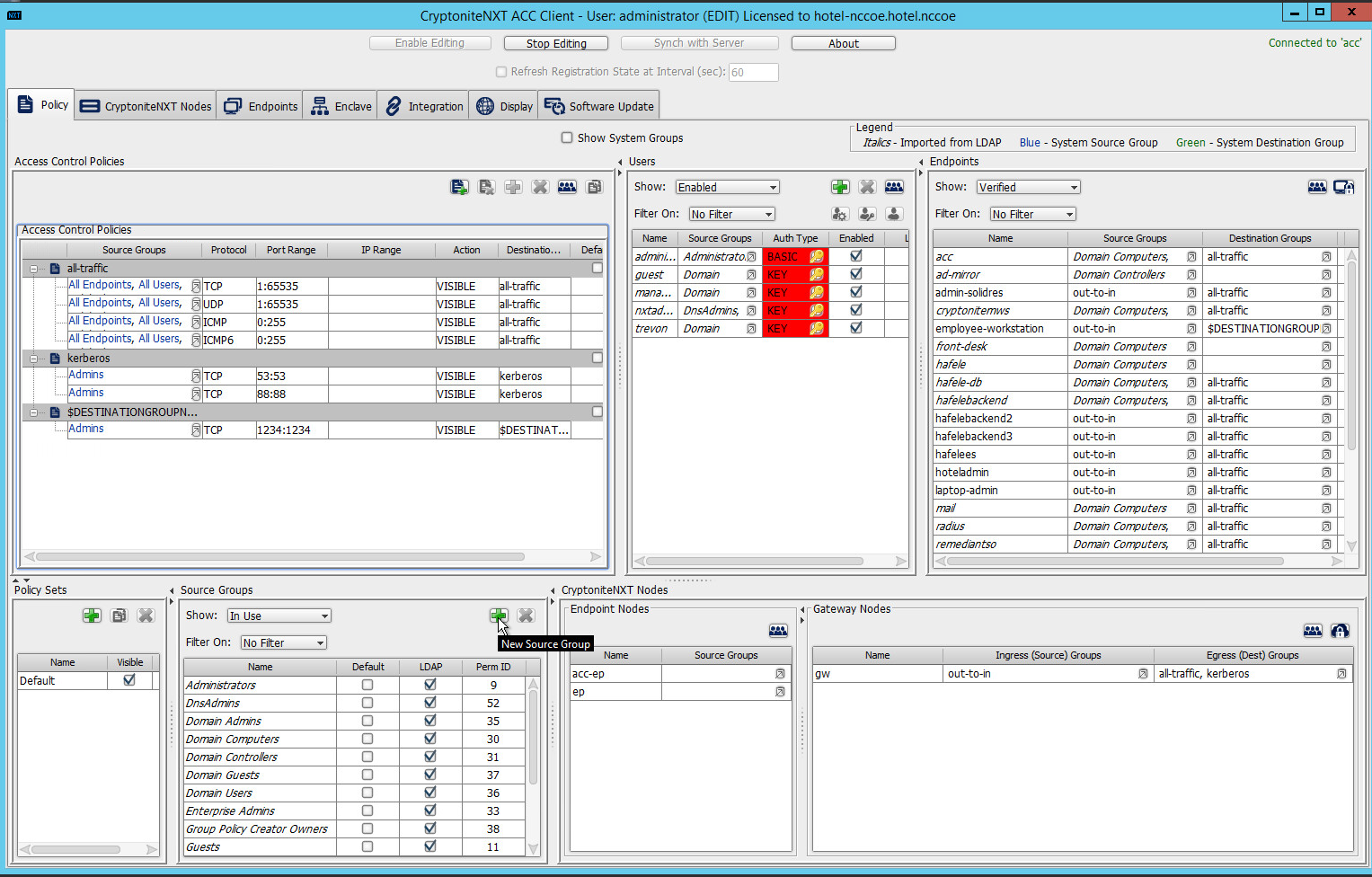
Input the desired source group name:
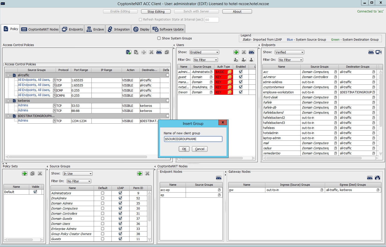
Click OK.
Under the Gateway Nodes box, select the left-most button (hover text: Assign Gateways to Ingress Groups):

Select the desired gateway under All Gateways:

Select the desired source group under Available Source Groups:
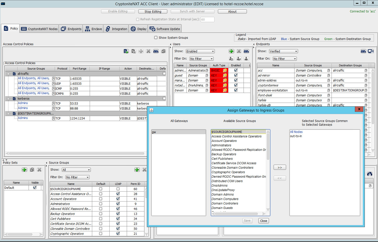
Click >>:
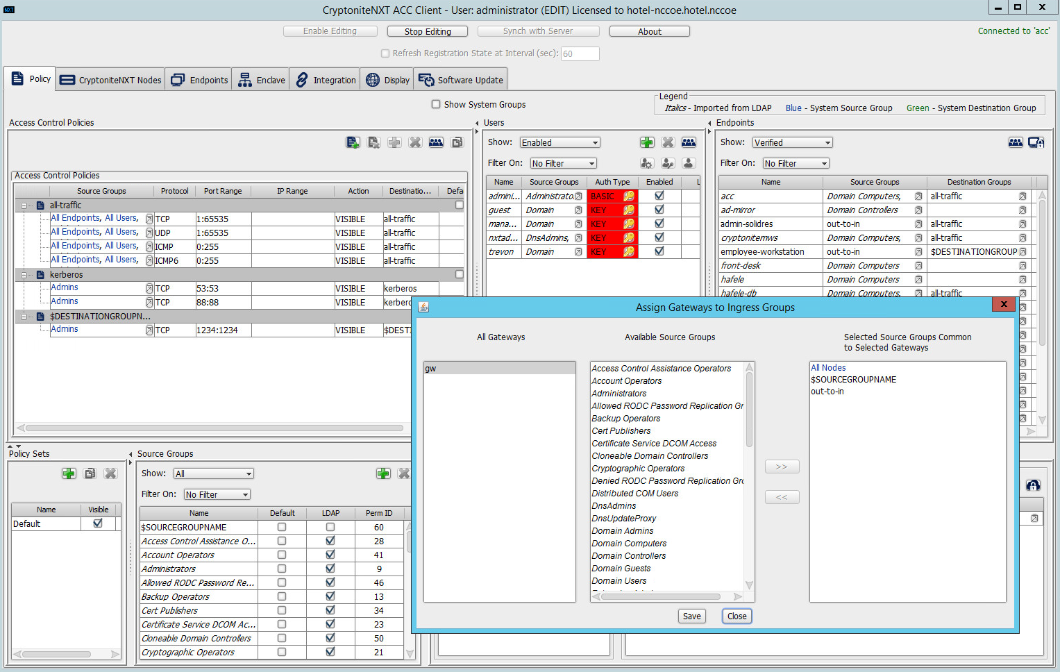
Click Save.
Click the right-most button (hover text: Assign Gateways to Egress Groups):
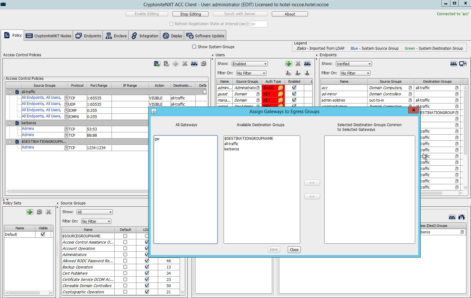
Select the desired gateway under All Gateways:

Under Available Destination Groups, select the destination groups from which you wish to draw access policies:
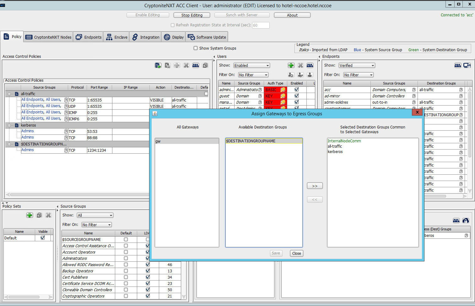
Click >>:
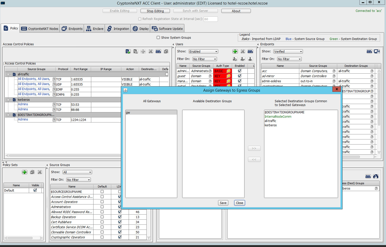
Click Save.
2.1.5 Creating Destination Groups
The following instructions detail creation of a generic destination group. They assume the same access to the CryptoniteNXT ACC GUI as in the previous instructions.
Click Enable Editing:
Under Access Control Policies, click the left-most icon depicting a piece of paper and a green plus sign (hover text: New Destination Group).
Create the name of a new destination group:
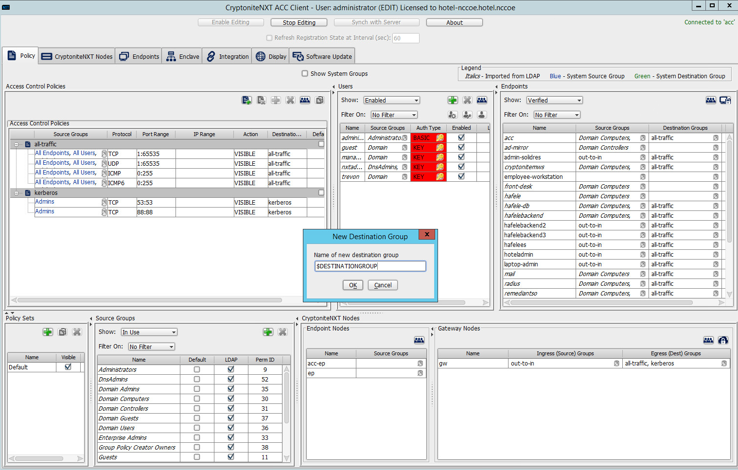
Click OK.
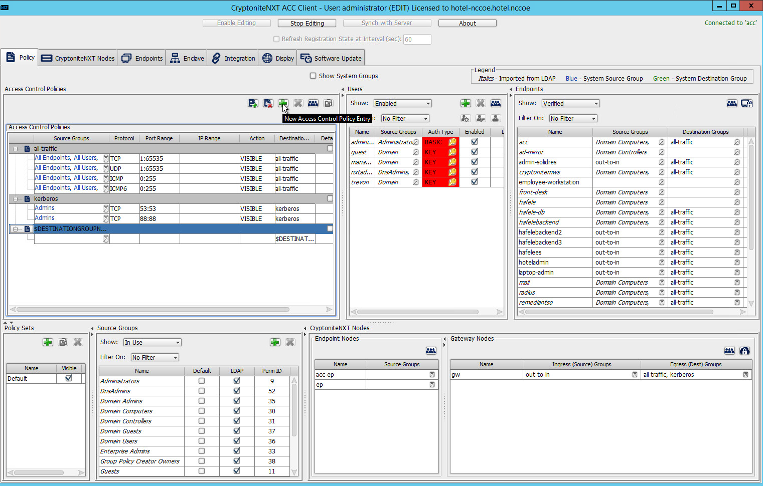
- If there is no blank row underneath the destination group, select the newly created destination group, and click the icon that contains only a green plus
sign (hover text: New Access Control Policy Entry):
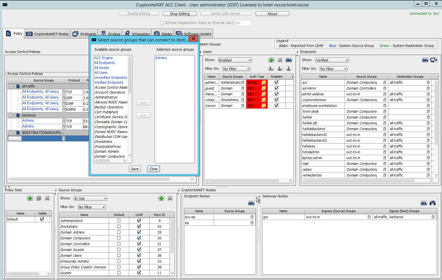
Click the small arrow icon in the Source Groups cell of the empty row (hover text: Click the arrow button to view/edit the source groups):
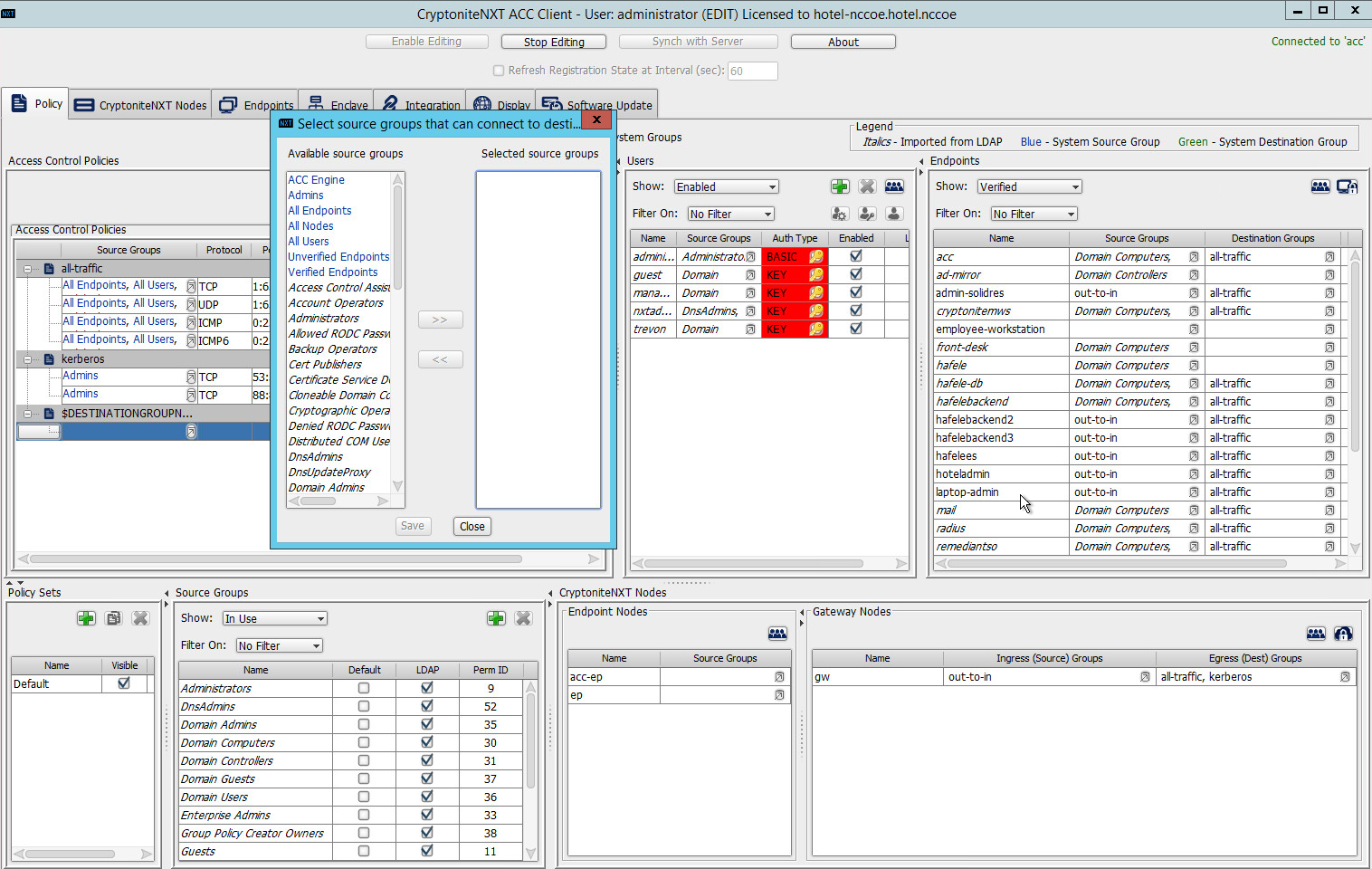
Select all source groups that you want to have this access:
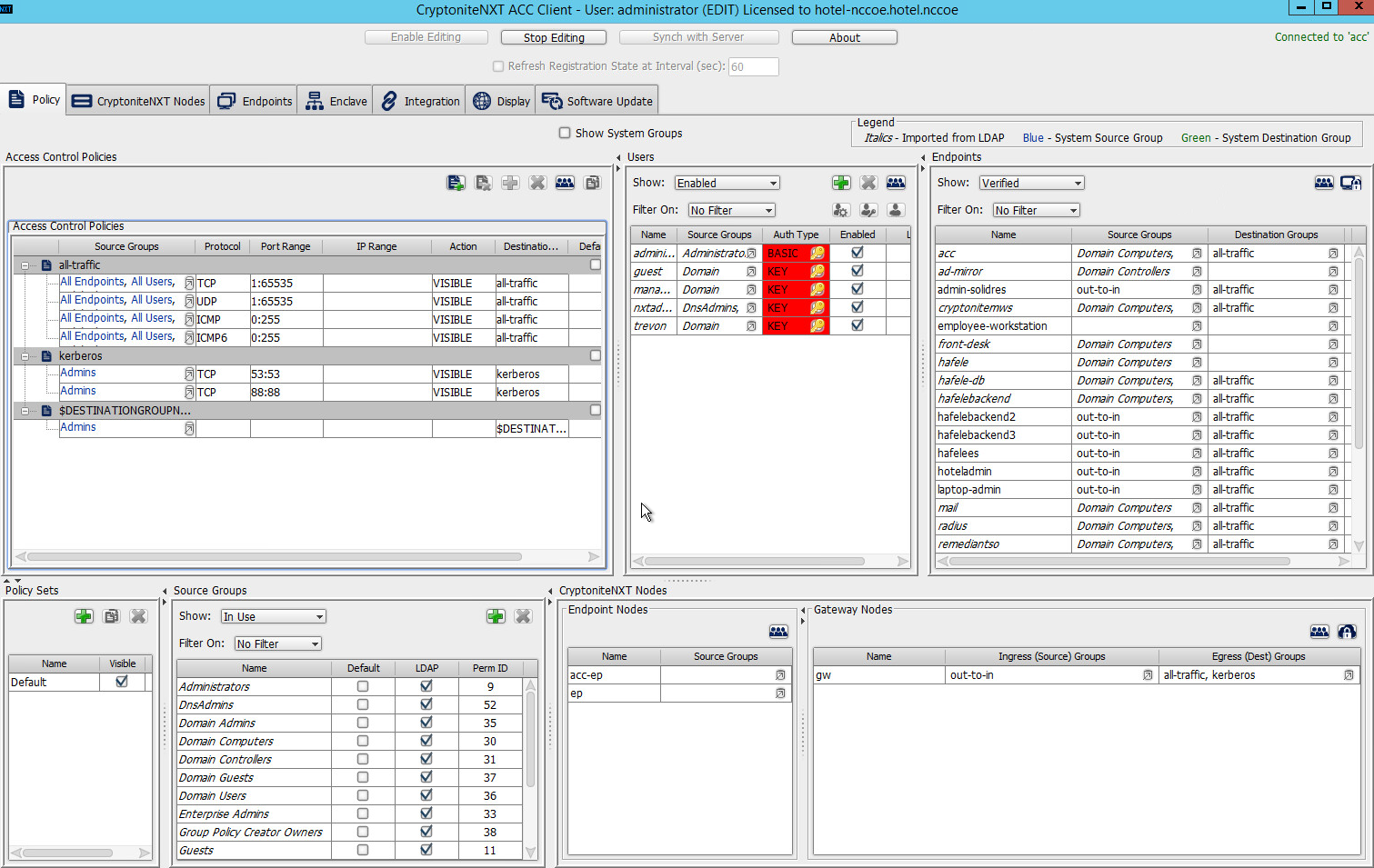
Click Save:
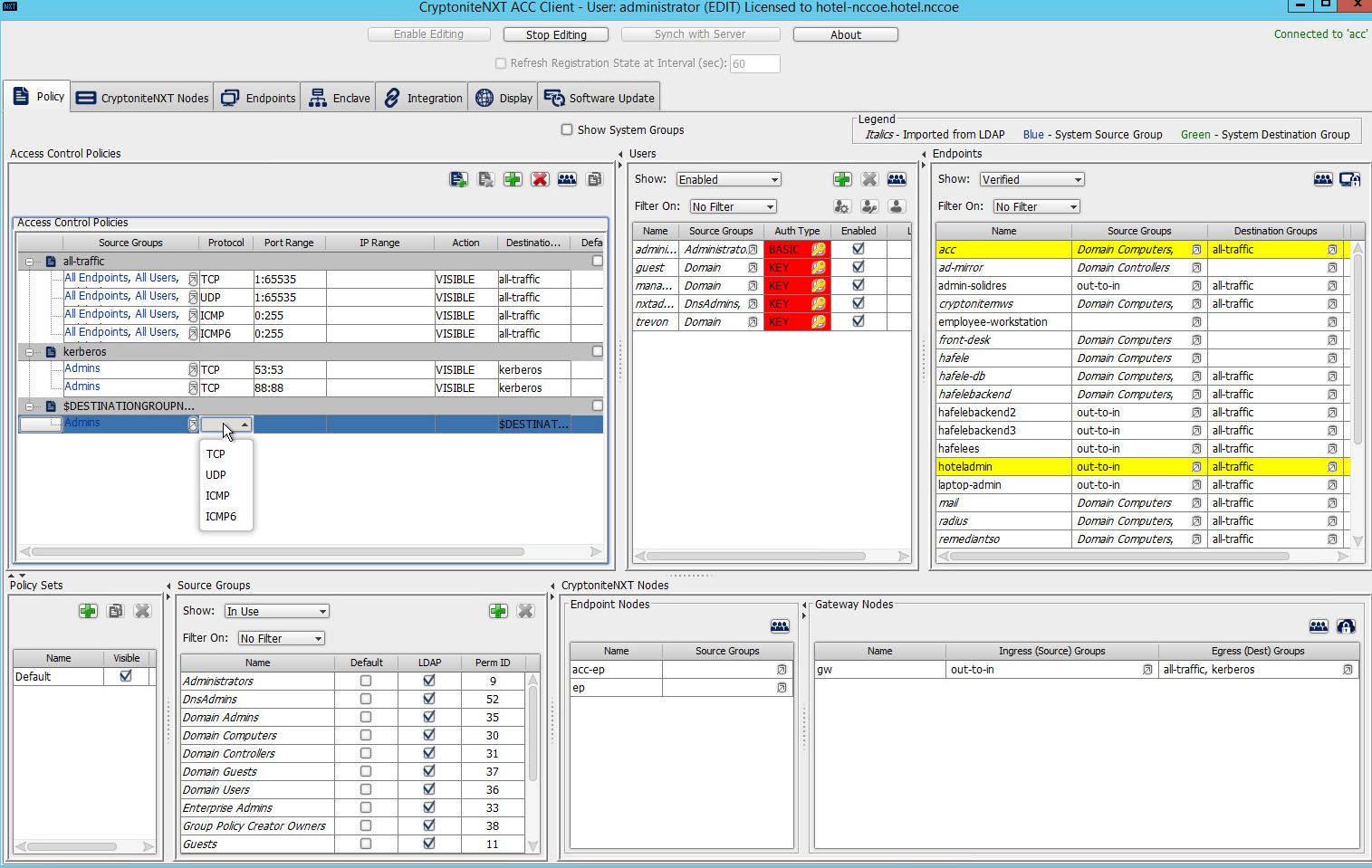
Click the Protocol cell of the row.
Select the protocol for which you wish to create an access policy:
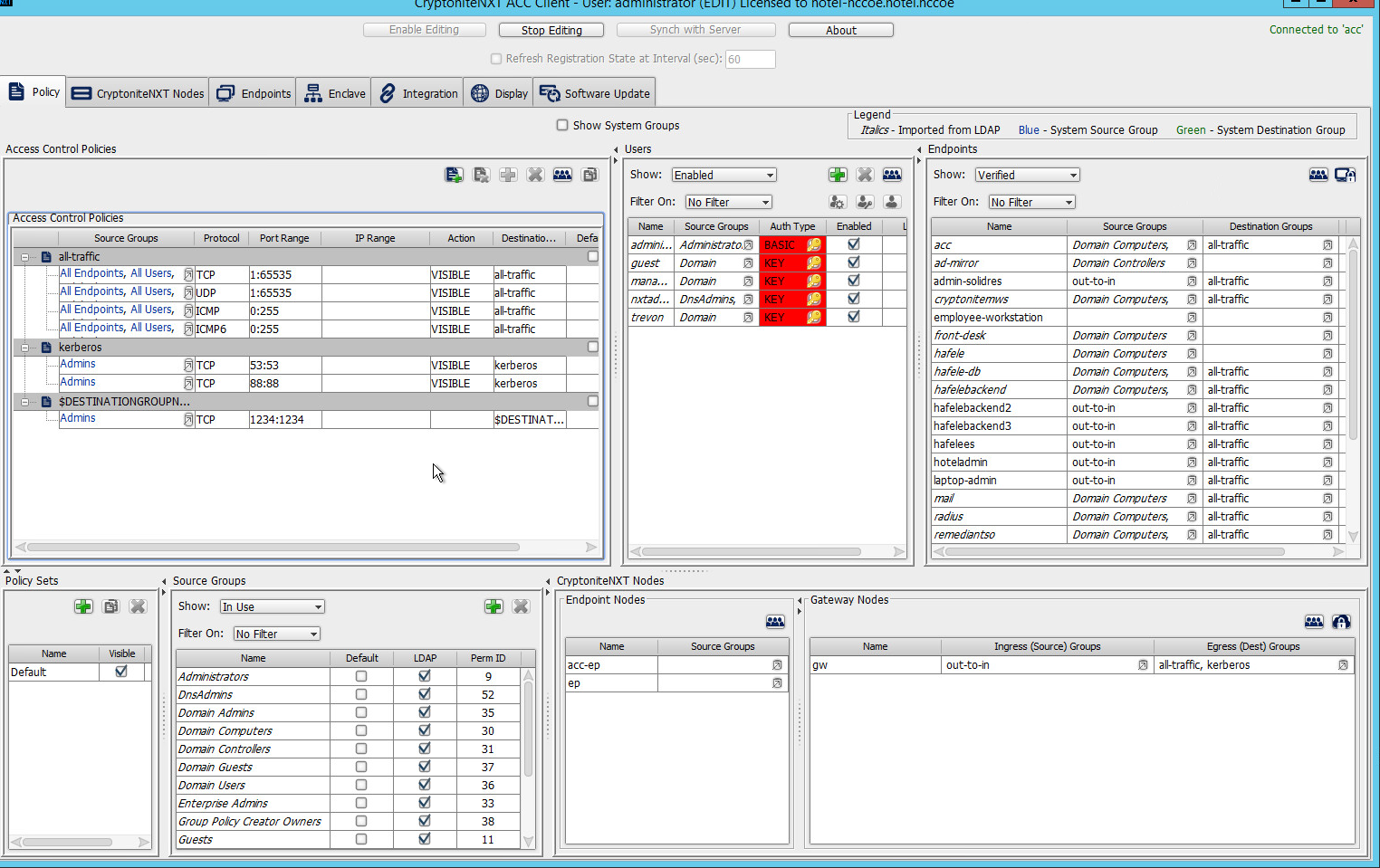
Click the Port Range cell of the row.
Input the desired port ranges for the protocol selected in step 10:
If desired, click the IP Range cell to modify this value. This is unused in this implementation.
Click the Action cell of the row:
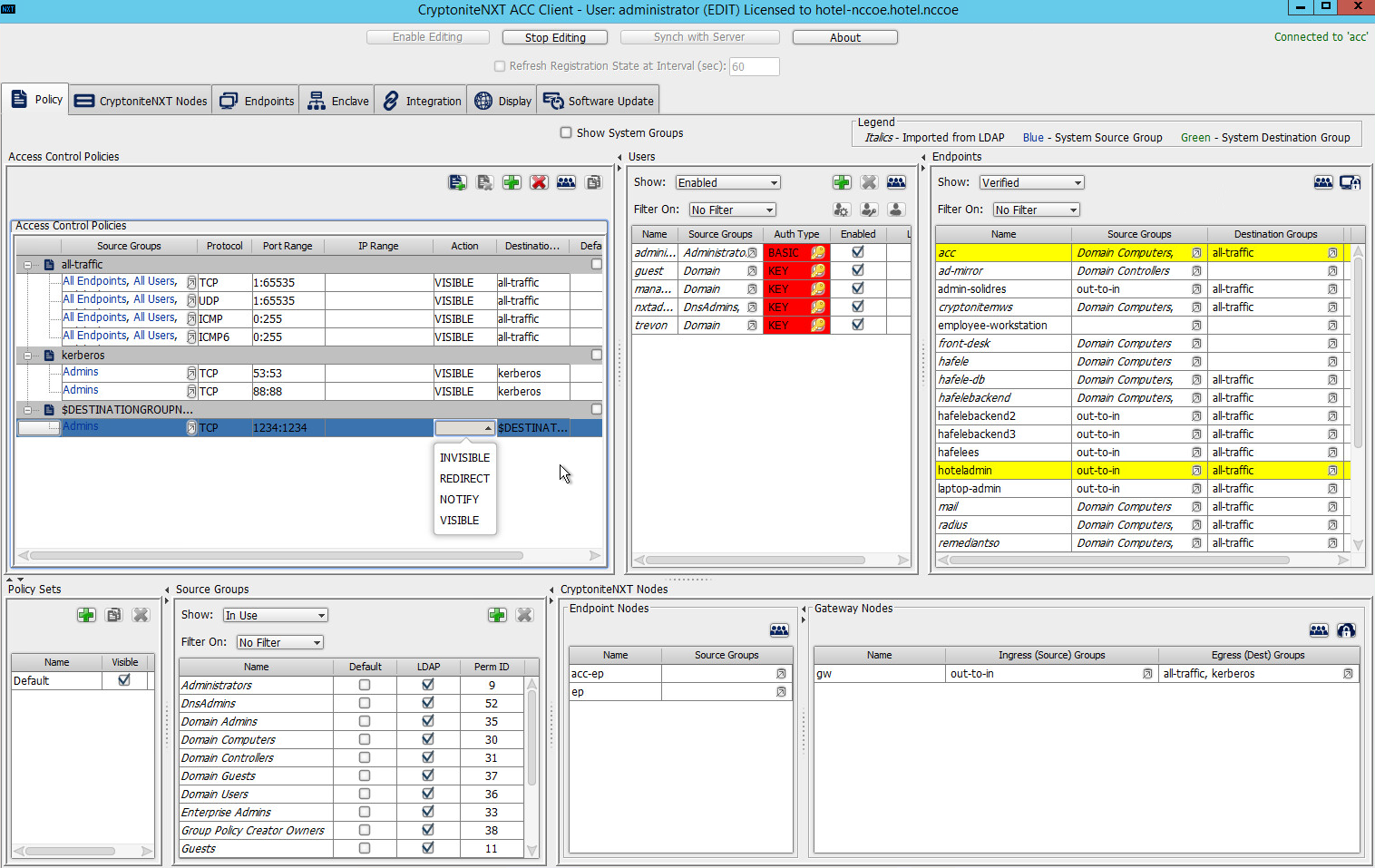
Set Action to VISIBLE to allow traffic of the described type; use INVISIBLE to block traffic of this type.
2.1.6 Applying Source Groups to End Points
The following instructions detail how to add an already-created source group to a specific end point within the CryptoniteNXT enclave. They assume the same access to the CryptoniteNXT ACC GUI as in the previous instructions.
In the Cryptonite Policy tab, click Enable Editing.
Locate the box labeled Endpoints to the right of the window, and right-click the desired end point:
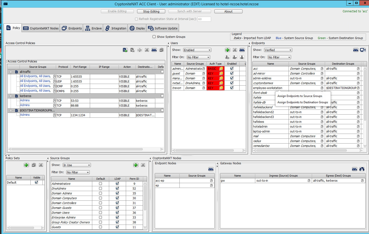
Select Assign Endpoints to Source Groups:
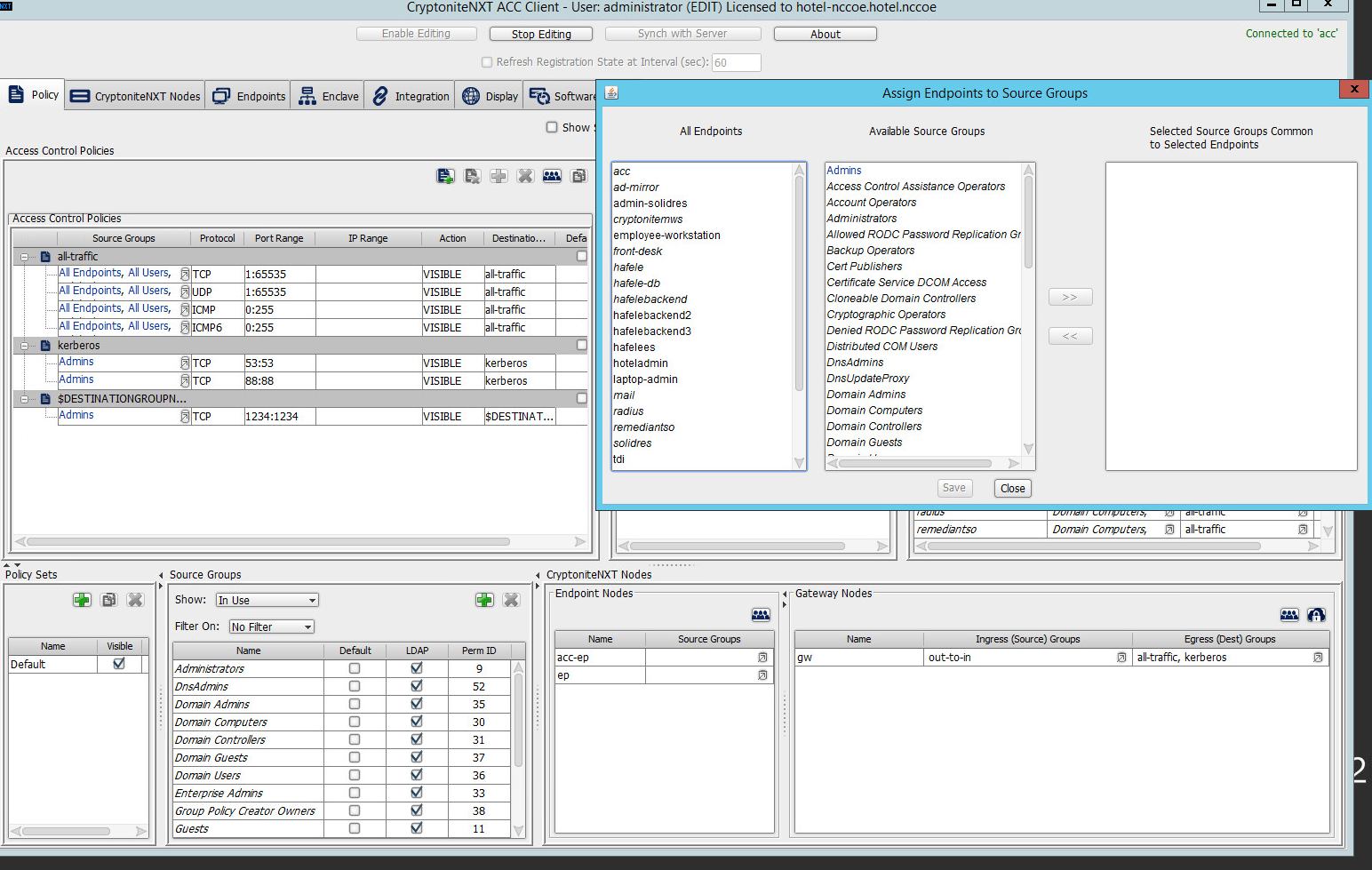
Find and select the desired end point under All Endpoints:
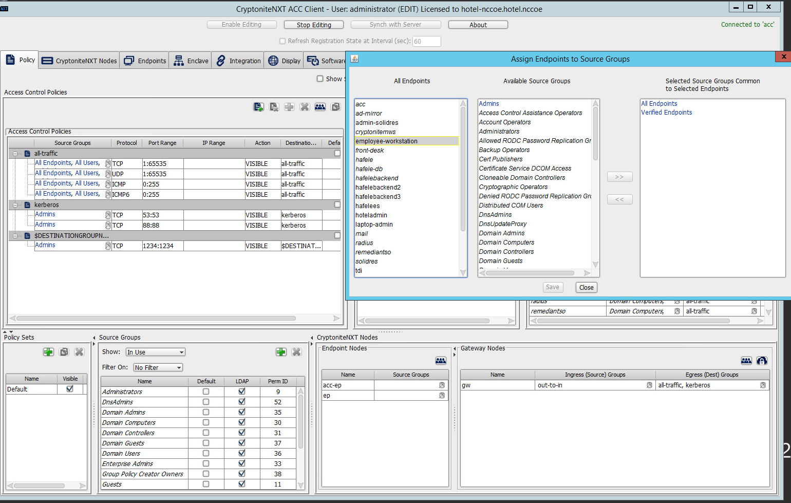
Find and select the desired source group under Available Source Groups:
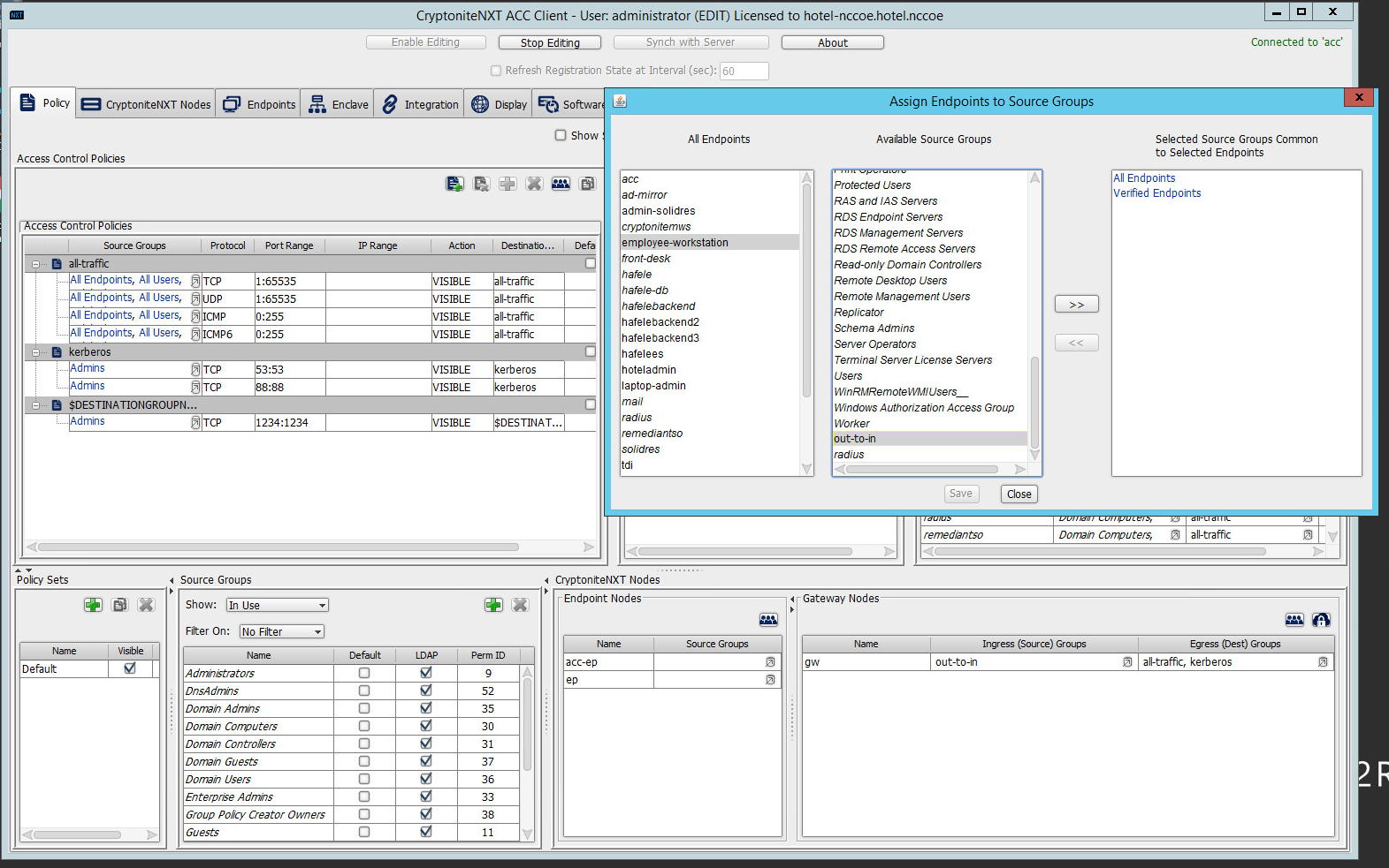
Click >>:
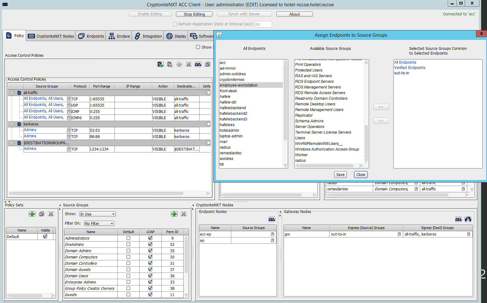
Click Save.
2.1.7 Applying Destination Group to End Points
The following instructions detail how to apply a previously created destination group to a registered end point.
In the Cryptonite Policy tab, click Enable Editing:
Locate the box titled Endpoints on the right hand of the screen. Right-click on any of the end points.
Select Assign Endpoints to Destination Groups:
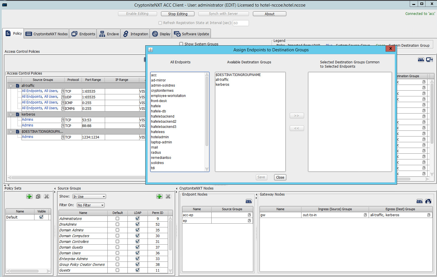
Locate and select the desired end point(s) under All Endpoints:
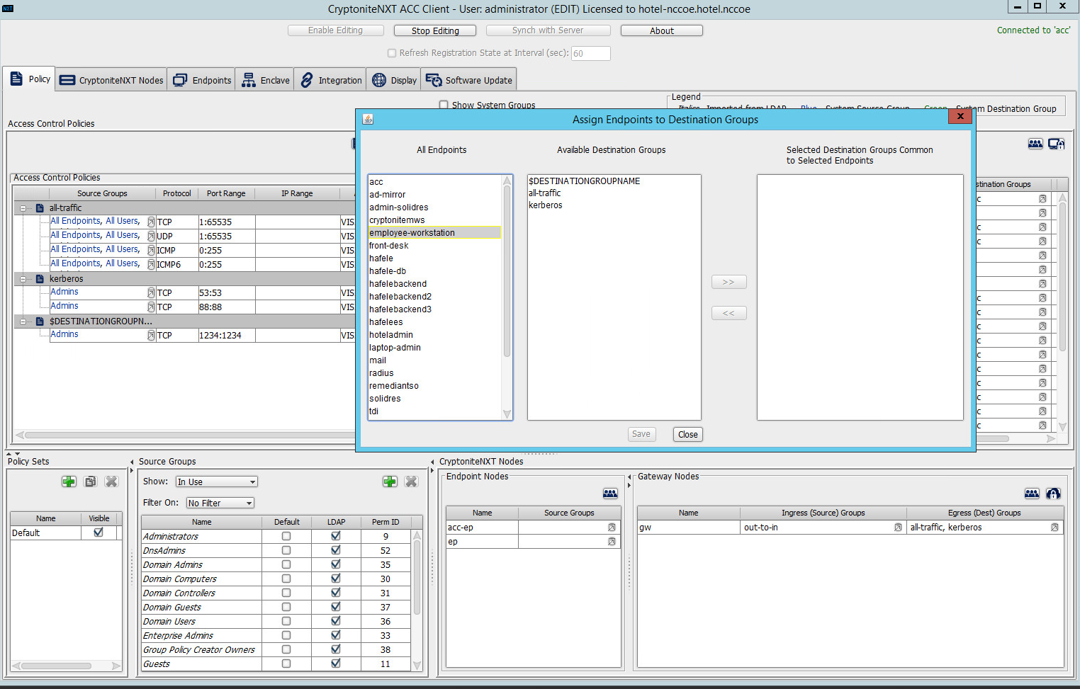
Select the desired destination group(s) under Available Destination Groups:
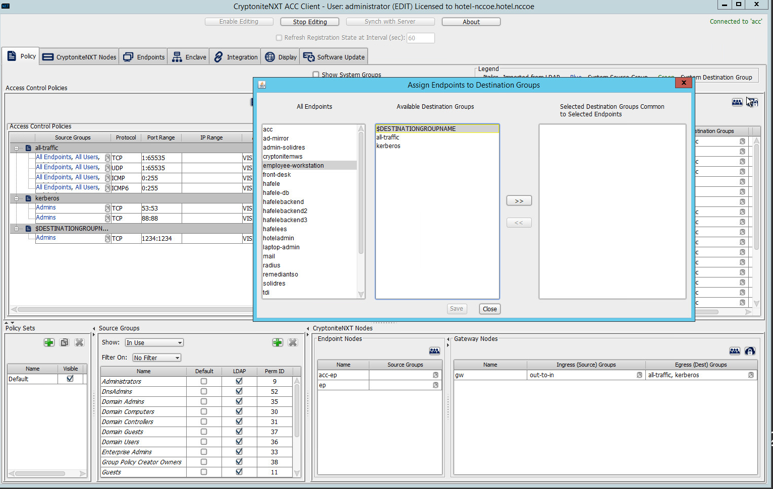
Click >>:
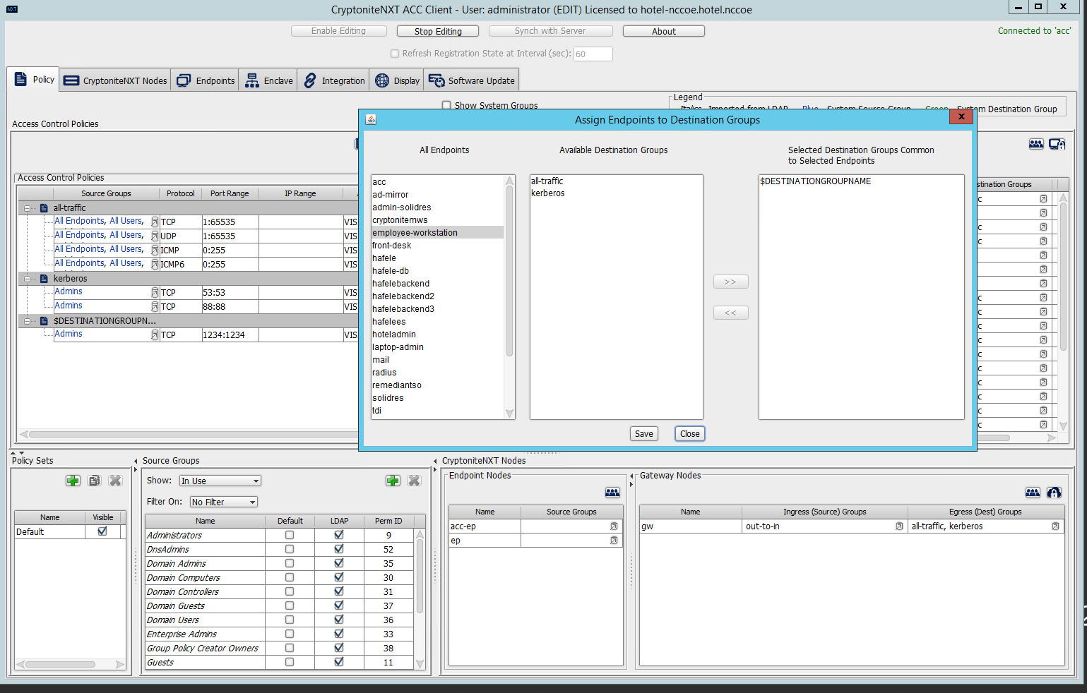
Click Save.
2.1.8 CryptoniteNXT Configuration for the PMS Reference Design
To gain the benefits of ZTA discussed in Volume B of this document, proper configuration of the CryptoniteNXT device is required. Non-use of the following network restrictions may limit network functionality and diminish the security benefits of the architecture. However, improperly configured rules can lead to a loss of network functionality. It may be correct for the adopting enterprise to install and configure its enterprise architecture and the remaining security architecture before applying the final configuration of the CryptoniteNXT device.
In this implementation, it is necessary to create the following source groups. If an organization’s desired architecture is different from the one described in this document, it is necessary to adapt the following instructions to avoid loss of network or security function. First, create the following source groups by using instructions from Section 2.1.4.
Remediant-Web-Access
Remediant-Access-Domain
Remediant-Access-Windows
RDP-Access
VNC-Access
HafeleES-Access
TDi-Access
Mail-Allowed
Create the destination groups shown in Table 2-1 by using the instructions in Section 2.1.5. All rows should be set to VISIBLE.
Table 2‑1 Required Destination Groups for CryptoniteNXT Configuration
Destination Group |
Source Group |
Protocol |
Port Range |
|---|---|---|---|
DNS |
All Endpoints |
TCP (Transport Control Protocol) |
53:53 |
All Endpoints |
UDP (User Datagram Protocol) |
53:53 |
|
Mail-Allowed |
TCP |
25:25 |
|
Mail-Allowed |
UDP |
25:25 |
|
Remediant-Domain |
Remediant-Access-Domain |
TCP |
389:389 |
Remediant-Access-Domain |
TCP |
636:636 |
|
Remediant-Access-Domain |
TCP |
123:123 |
|
Remediant-Linux |
Remediant-Access-Linux |
TCP |
22:22 |
Remediant-Web |
Remediant-Web-Access |
TCP |
80:80 |
Remediant-Web-Access |
TCP |
443:443 |
|
Remediant-Web-Access |
TCP |
3000:3000 |
|
Remediant-Web-Access |
TCP |
22:22 |
|
Remediant-Windows |
Remediant-Access-Windows |
TCP |
137:139 |
Remediant-Access-Windows |
TCP |
445:445 |
|
Remote-Access-Linux |
VNC-Access |
TCP |
5901:5901 |
Remote-Access-Windows |
RDP-Access |
TCP |
3389:3389 |
RDP-Access |
UDP |
3389:3389 |
|
Solidres-Admin-Web |
Verified Endpoints |
TCP |
80:80 |
Verified Endpoints |
TCP |
443:443 |
|
Solidres-Public |
All Endpoints, All Users |
TCP |
80:80 |
All Endpoints, All Users |
TCP |
443:443 |
|
TDi-Incoming |
TDi-Access |
UDP |
514:514 |
TDi-Access |
TCP |
5176:5176 |
|
TDi-Access |
TCP |
443:443 |
|
Hafele-HafeleES |
HafeleES-Access |
TCP |
8443:8443 |
Apply the source and destination groups to the end points shown in Table 2-2 per instructions in Section 2.1.4 and Section 2.1.5. In some deployments, the adopting enterprise may have included an all-traffic or similar rule to facilitate installation of other devices in the protected zone. Remove all-traffic rules that allow elevated network privileges at this stage.
Table 2‑2 Required Source-Destination Mappings for CryptoniteNXT Configuration
End Point |
Source Groups |
Destination Groups |
|---|---|---|
Solidres administrator interface |
Mail-Allowed |
Remediant-Linux Remote-Access-Linux Solidres-Admin-Web |
Solidres public web interface |
Solidres-Public Remediant-Linux Remote-Access-Linux |
|
enterprise management workstation |
Remediant-Web-Access TDi-Access |
Remediant-Access-Windows |
employee workstations |
TDi-Access |
|
mail server |
Mail-Allowed |
|
Remediant SecureONE |
Remediant-Access-Domain Remediant-Access-Linux Remediant-Access-Windows |
Remediant-Web |
TDi ConsoleWorks |
RDP-Access VNC-Access |
Remediant-Linux TDi-Incoming |
2.2 Access Control Platform—TDi ConsoleWorks
This section of the guide provides installation and configuration guidance for the access control platform, which gives access control for system administration in the example implementation. The access control platform performs authentication of user and devices and provides console access to the PMS, management workstation, front desk workstations, and Häfele back-end server.
TDi ConsoleWorks is the access control platform used in the PMS reference design and maps to the Identity and Access Management component of the ZTA.
2.2.1 Access Control Platform–TDi ConsoleWorks—Overview
The access control platform TDi ConsoleWorks performs the access control functionality in the PMS reference design.
TDi ConsoleWorks was deployed as a virtual machine (VM) in the NCCoE hospitality lab. Installation instructions are available at the TDi Technologies support site, which may be useful if the adopting enterprise’s deployment differs substantially from the one used for this project.
TDi ConsoleWorks is employed here to create secure connections to end points. In addition to streamlining access to network end points such as the PMS and the administrator workstation, it can be used to audit and track those connections to ensure that privileged access is not abused.
The location of the access control platform in the reference architecture is highlighted in Figure 2-2 below.
Figure 2‑2 Access Control Platform in the Reference Architecture
2.2.2 Access Control Platform—TDi ConsoleWorks—Requirements
The following subsections document the software, hardware, and network requirements for the access control platform for version 5.2-0u1.
2.2.2.1 Hardware Requirements for Access Control Platform
TDi recommends amending hardware requirements for ConsoleWorks depending on the size of the deployment, but at minimum, allocate 2 GB of storage to the machine.
2.2.2.2 Software Requirements for Access Control Platform
TDi ConsoleWorks 5.2 requires an operating system (OS) from the following list.
64-bit RedHat Linux 7.0, 7.5, 8.0, or equivalent
Windows Server 2012 R2
Windows Server 2016
Windows Server 2019
This build utilized a Community Enterprise Operating System (CentOS) 7.3 64-bit server.
To install TDi ConsoleWorks, access must be available to the machine’s command line interface (CLI). It will also be necessary for network access to be available to the machine’s IP address (retrievable via the ifconfig command) during installation. For this build of TDi ConsoleWorks 5.2, installation is conducted on a VM in the NCCoE virtual environment.
2.2.2.3 Network Requirements of the Access Control Platform
In addition to the described access to the CLI, the access control platform requires network access to the TDi ConsoleWorks back-end server as well as to any end points to which it will connect. The network must support secure transmission protocols. TDi ConsoleWorks relies on existing means to connect to protected end points, such as Secure Shell (SSH) or Remote Desktop Protocol (RDP).
Note that use of a zero trust networking solution such as CryptoniteNXT can limit availability of network resources when improperly configured. For this reason, we recommend setting up and verifying TDi ConsoleWorks before applying rules on the CryptoniteNXT device, as stated in Section 2.1.8.
2.2.3 Access Control Platform—TDi ConsoleWorks—Installation
The installation procedure consists of the following steps:
Download the software.
Run the installation script, customizing options to reflect the enterprise.
Create a secure sockets layer (SSL)-capable invocation of TDi ConsoleWorks, and generate an SSL certificate to match.
Download and apply a license.
Create a gateway to allow GUI functionality.
Create connections to the desired end points within the enterprise.
The instructions below rely on the assumed access to the TDi ConsoleWorks CLI. The installation media file name takes the form
ConsoleWorksSSL-<version>.signed,x86_64.rpm.
If the media is not on the installation target, add it through external media or via the scp command. Obtaining the installation media requires an account on the TDi Technologies support page and can be accessed at https://support.tditechnologies.com/get_consoleworks/linux.
Create a directory in the /tmp folder:
mkdir /tmp/conwrksMove the ConsoleWorks installation media to /tmp/conwrks:
mv path/to/media /tmp/conwrksChange directory to the conwrks directory, and verify that the terminal prompt reflects the change:
cd /tmp/conwrks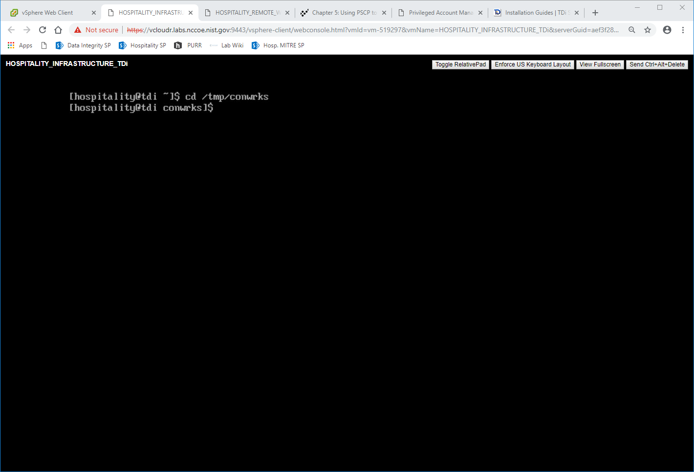
Execute the installation media:
yum localinstall consoleworksssl-<version>_x86_64.rpm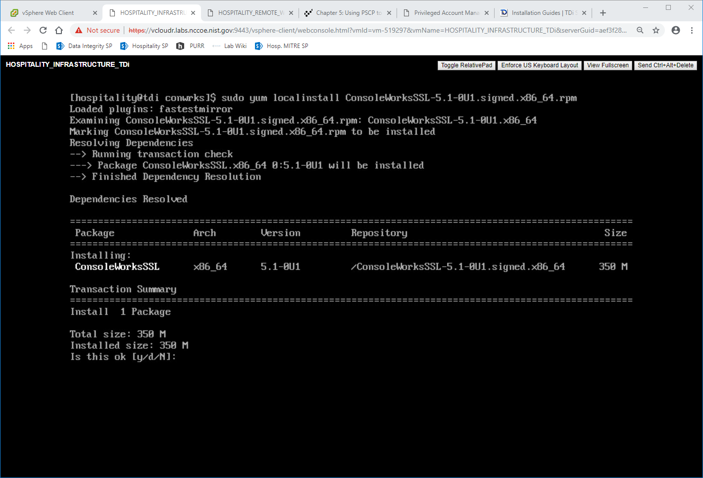
Enter the option
yto begin the installation.Wait for the installation to complete. Upon completion, the text
Installed: ConsoleworksSSL.[VERSION]should appear: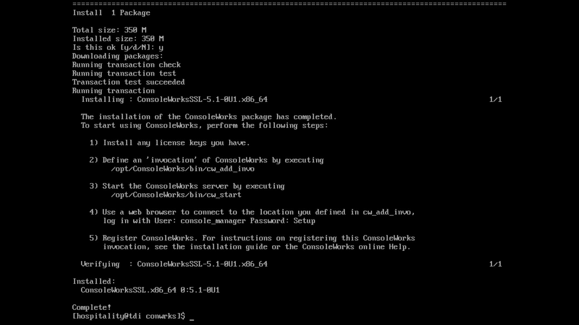
2.2.3.1 Create SSL Invocation
Escalate to a super user shell by executing the following command and entering the machine password:
suVerify that the command has executed by seeing that the prompt has changed to
root@tdi: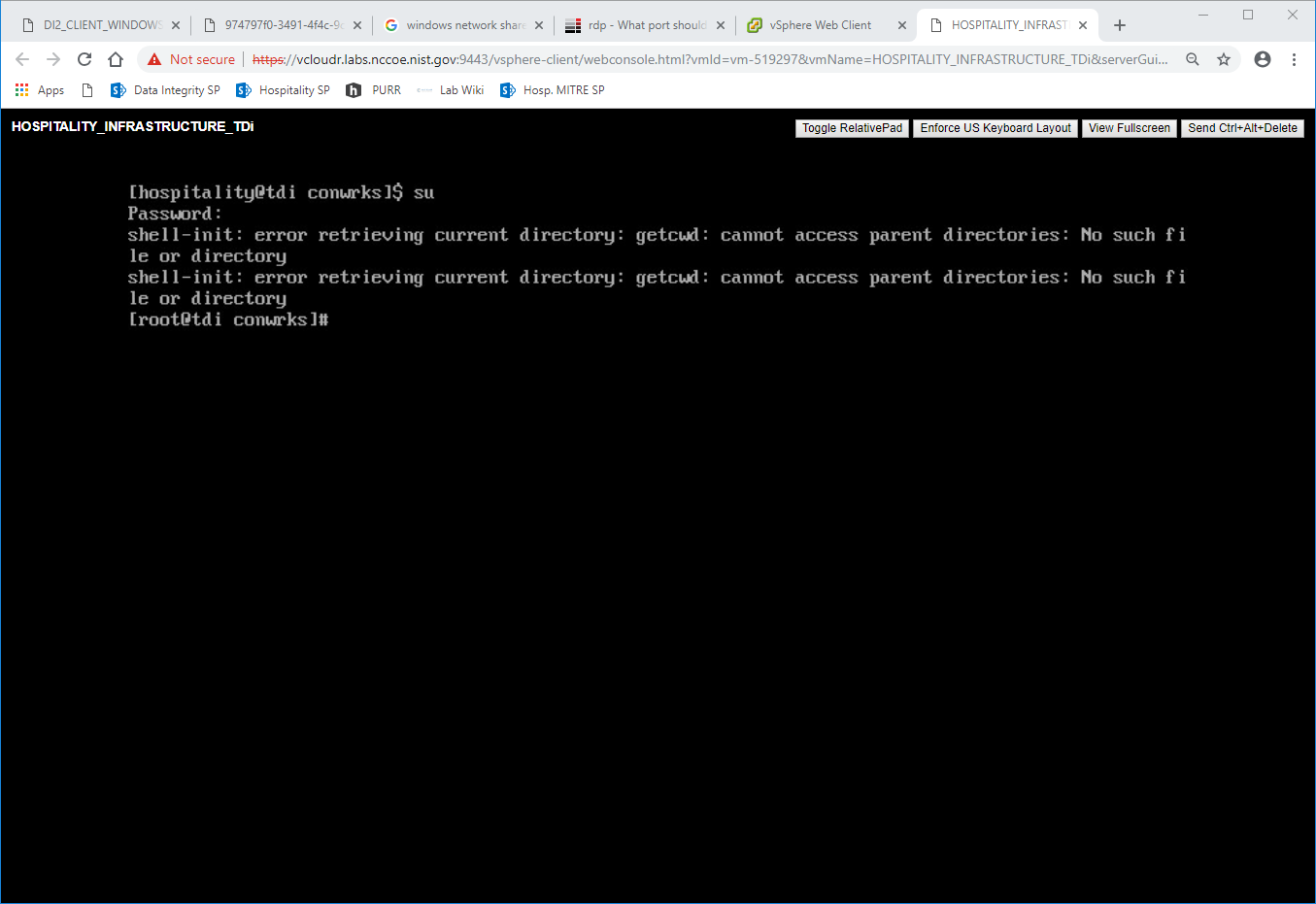
Begin invocation creation with the following command:
/opt/ConsoleWorks/bin/cw_add_invoRead the End User License Agreement. Accept by typing
yfollowed by the enter key.- Enter the following information, in order. The values used in this implementation are provided for context but may not be appropriate for your enterprise.
Press enter to use the default value provided by the terminal:
desired console name [HotelConsole]
web service port [5176]
enabled syslog functionality [y]
Verify that the desired values have been entered:
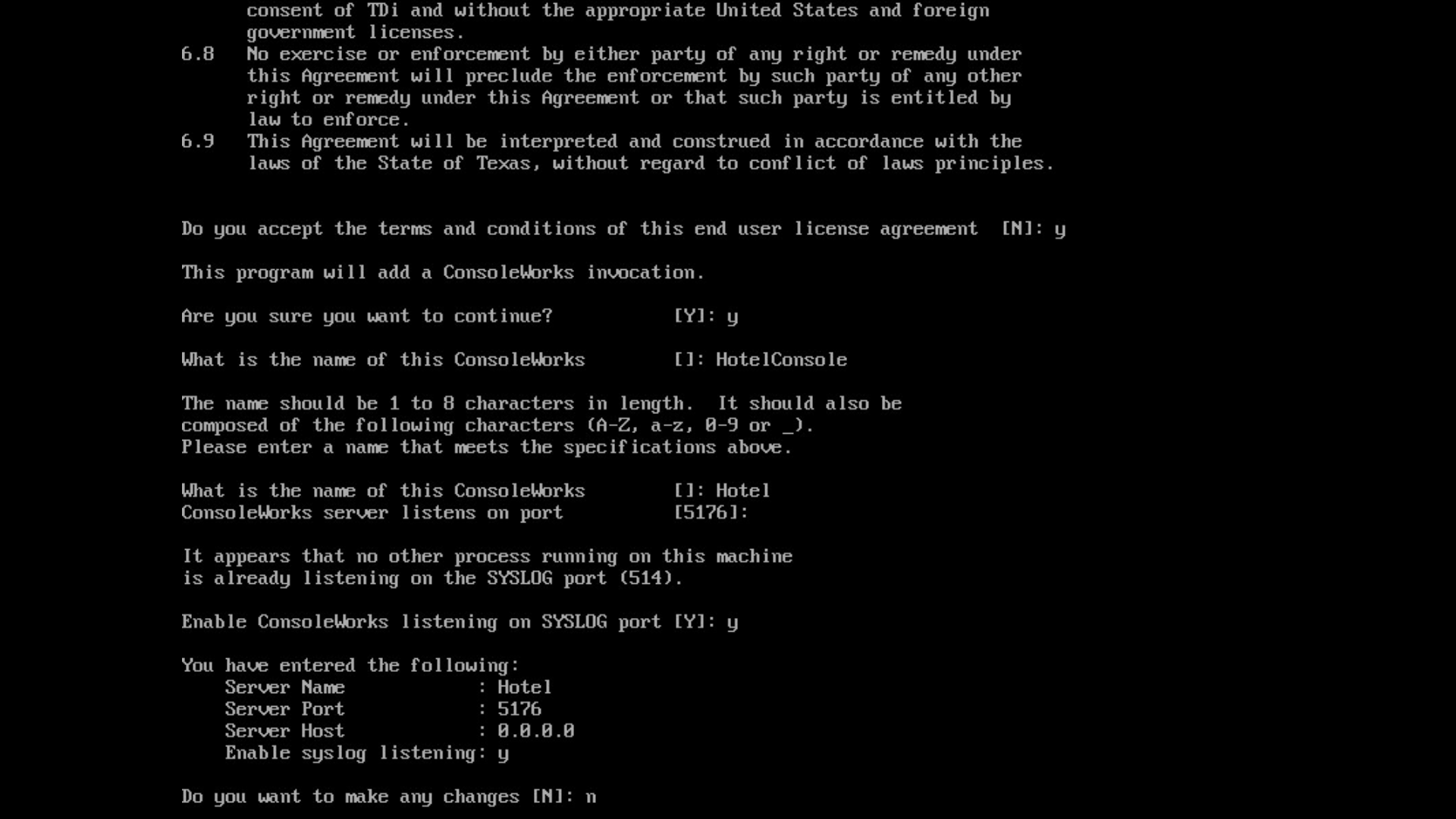
If satisfied, type n for no changes.
2.2.3.2 Create SSL Certificate
These instructions rely on execution of Section 2.2.3.1 and are a continuation of the invocation creation process. They are separated here for clarity.
Input
1to allow the SSL invocation creation.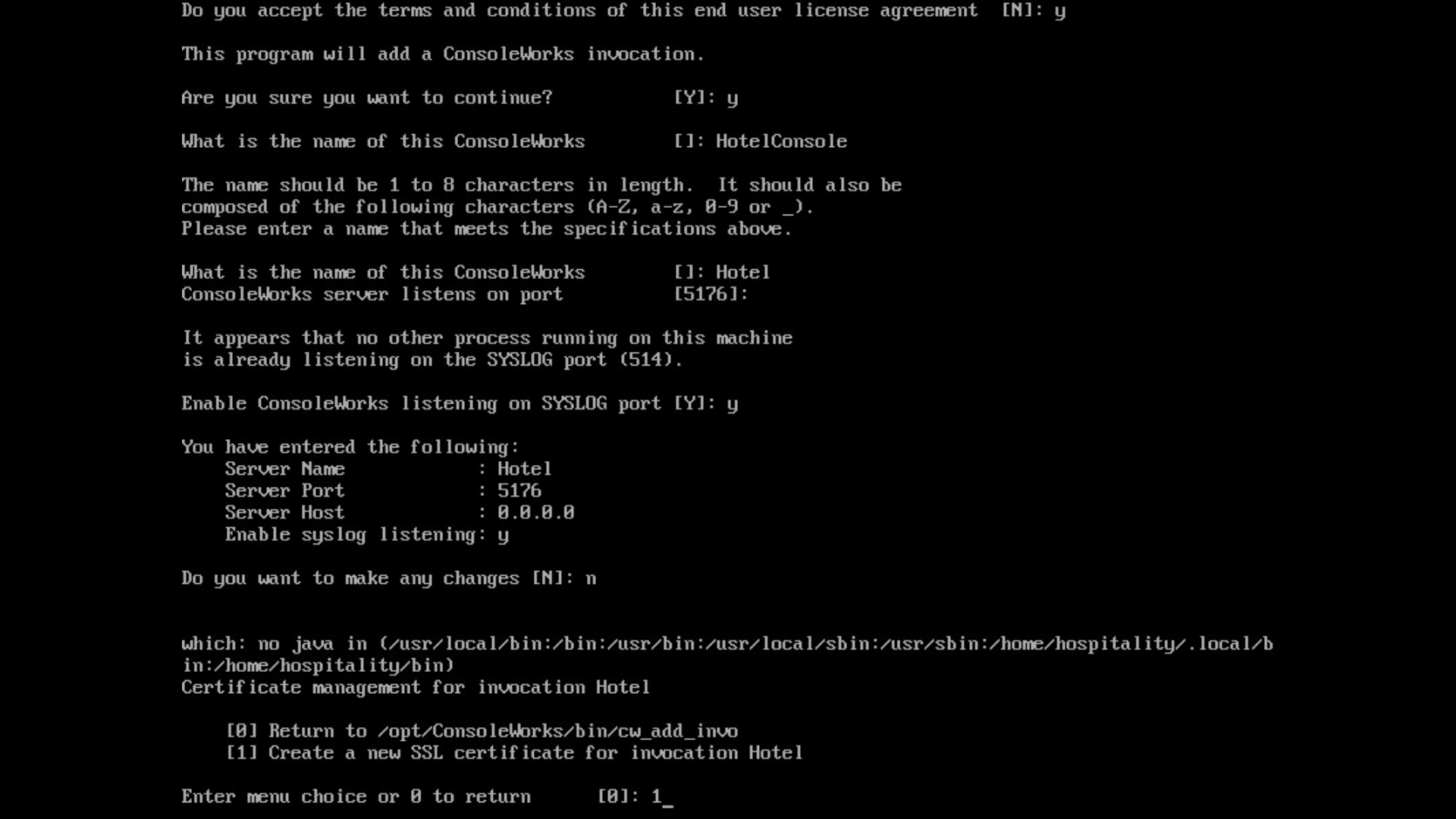
Enter the following information, pressing enter after each entry:
country code
state or provincial name
city or locality
company or organization name
department name
FQDN
email address of the person responsible for the certificate
password to protect the certificate
the same password to confirm
name of the person responsible for the certificate
the number of days for which the certificate will be valid (730 is the default value)

Input
0to complete the invocation addition: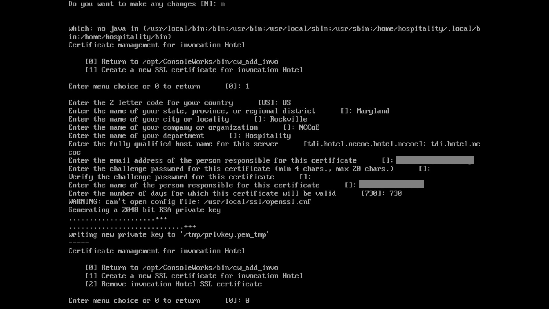
2.2.3.3 Apply License
The following instructions rely on continued access to the CLI of the TDi ConsoleWorks device.
Execute the shell script provided as the license by TDi Technologies:

Input
Y: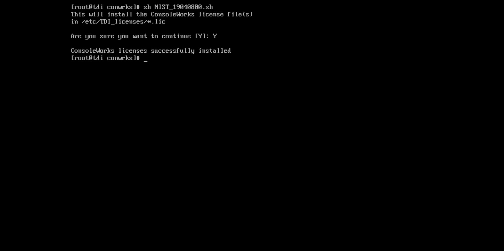
2.2.3.4 Start-Up
Execute the following command, and note the address and port provided in the console response:
/opt/ConsoleWorks/bin/cw_start Hotel
Execute the following command:
/opt/ConsoleWorks/bin/cw -setsid Hotel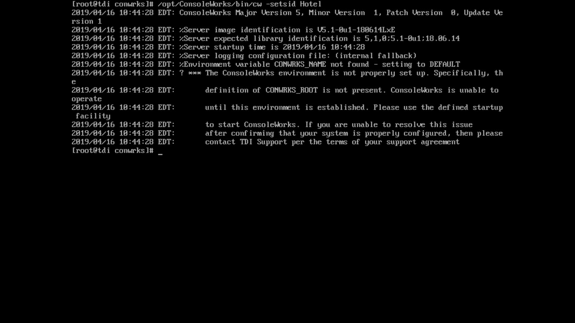
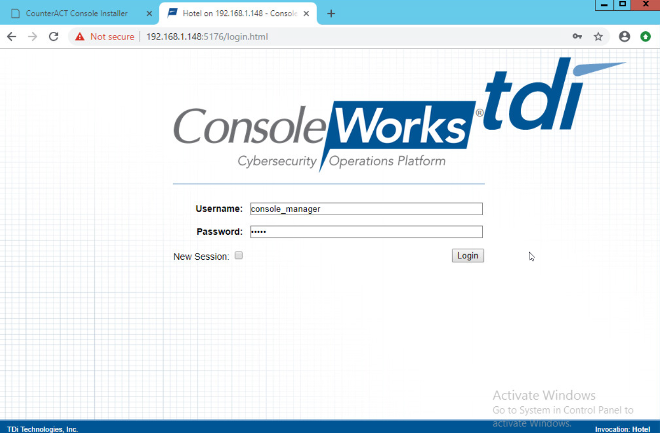
On another machine, open the web page provided in step 1 or the IP followed directly by the port number:
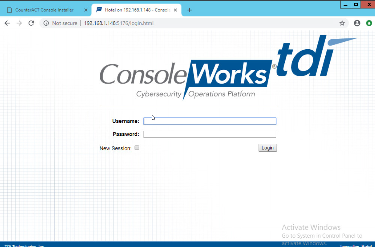
Log in with default credentials console_manager/Setup:
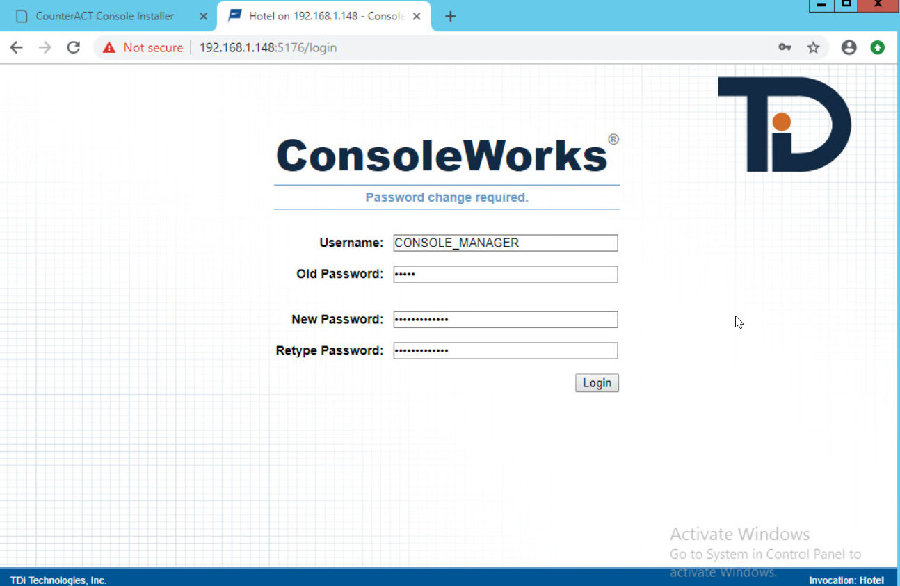
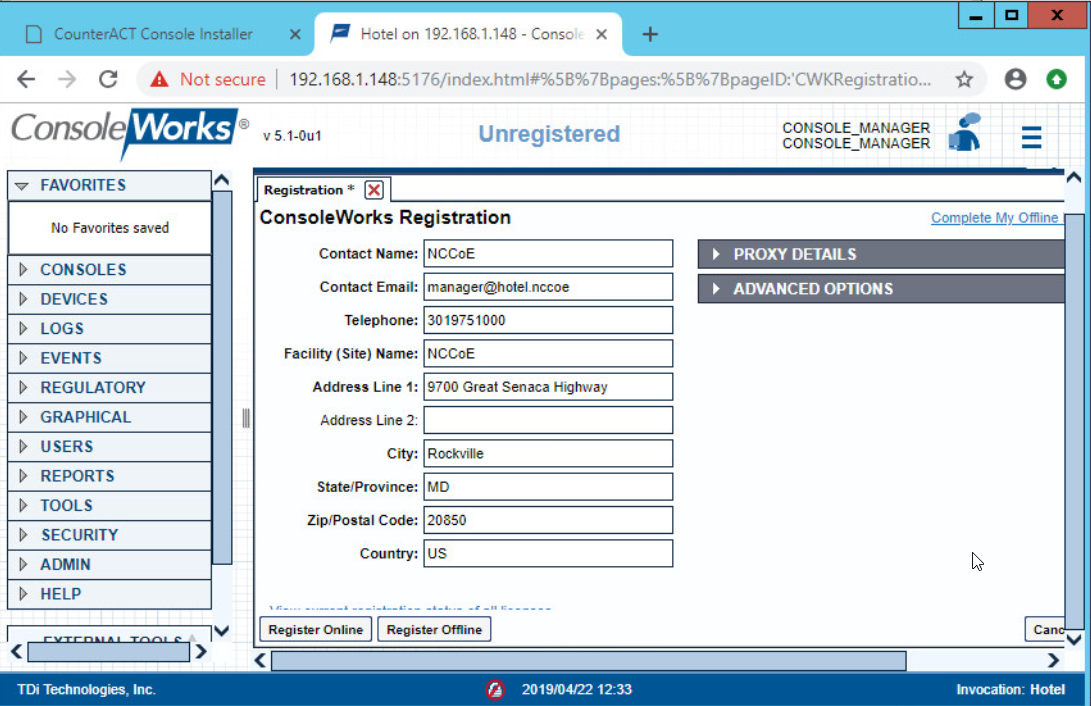
Change the default password, and click Login:
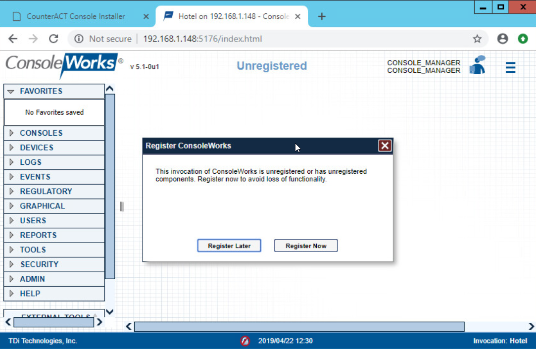
Click Register Now:
Fill out contact details, and click Register Online:
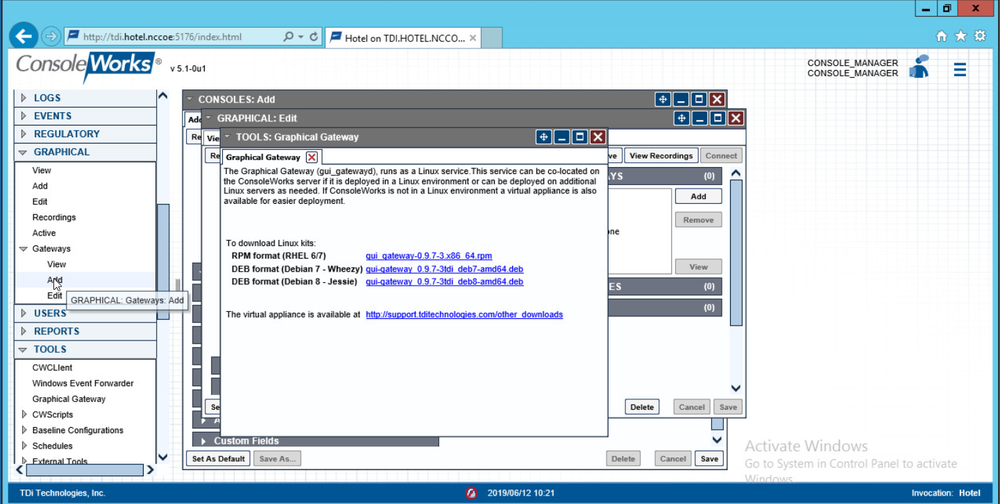
2.2.3.5 GUI Gateway Installation
Ensure that the following packages are installed via $yum install [pkg_name], where [pkg_name] is:
-freerdp-libs
-uuid
-cairo
-libvncserver
-libpng12
-freerdp-plugins
-net-tools
-openssh-clients
-open-vm-tools
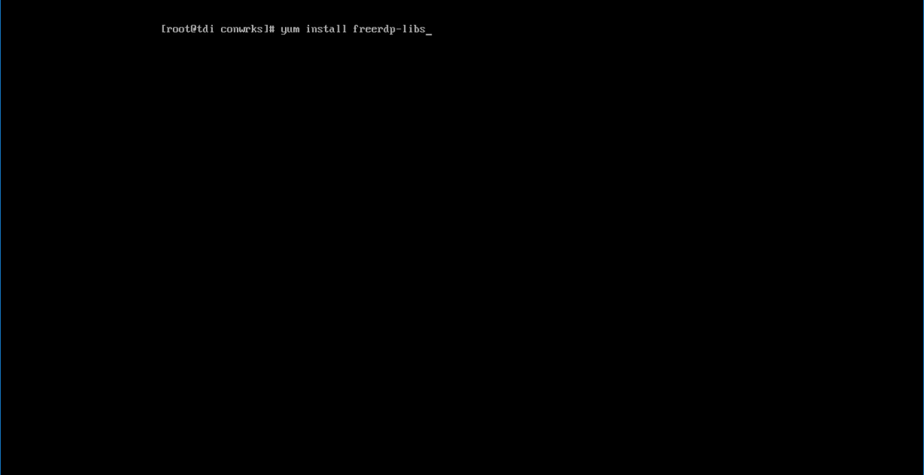
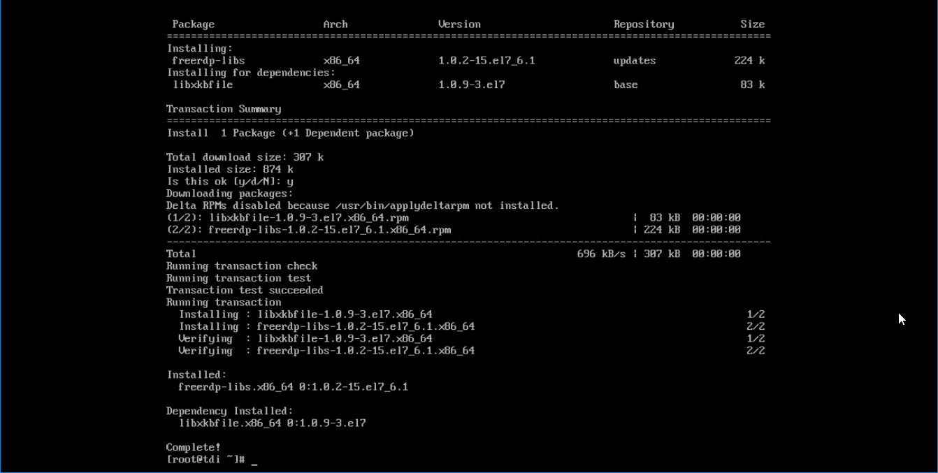
Type
yto allow installation: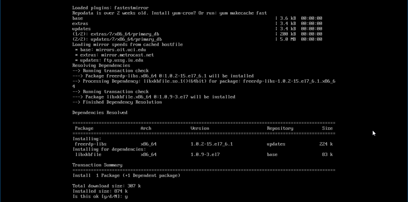
Repeat steps 1 and 2 for all other packages in the list:
Download gui_gateway-0.9.7-3.x86_64.rpm (or the latest version), and place on the TDi back-end server:
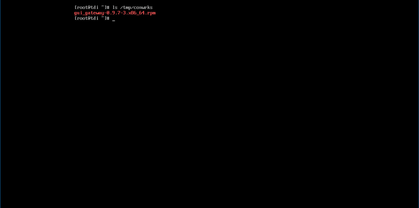
Install with this command:
rpm -ivh gui_gateway-0.9.7-3.x86_64.rpm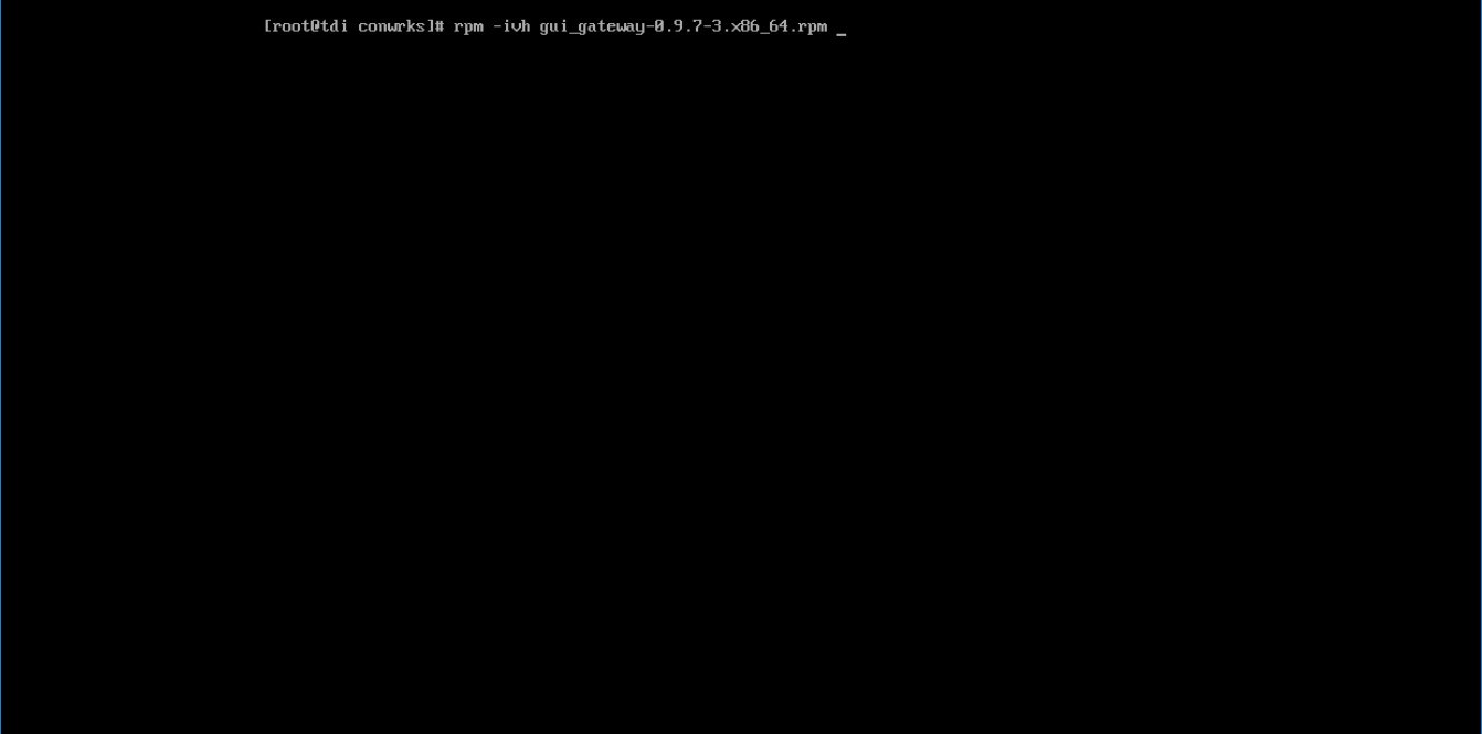
Execute the following command if you are conducting a local installation, where the gateway is on the same server as the TDi ConsoleWorks invocation:
/opt/gui_gateway/install_local.sh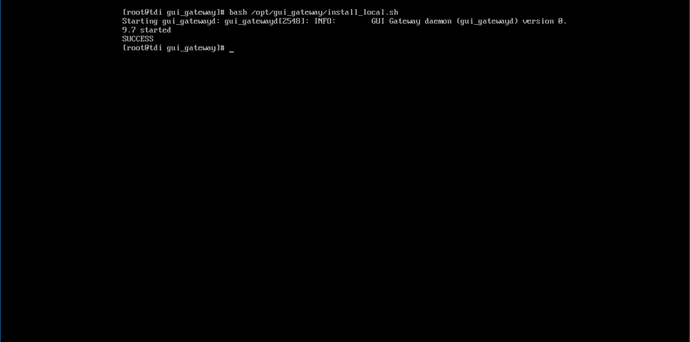
Execute the following to start the gateway:
service gui_gatewayd start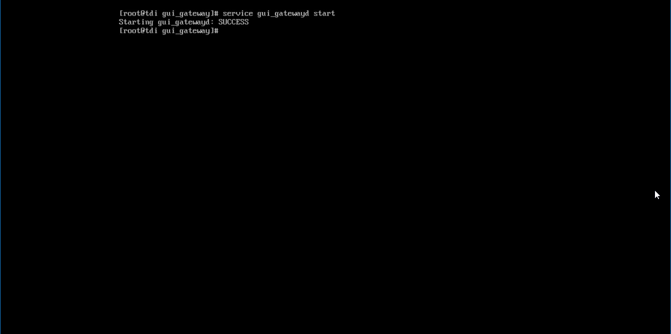
2.2.4 Add Gateway to GUI
The instructions below are executed on a separate virtual or physical machine that has network access to the TDi ConsoleWorks back-end server through the
previously configured web port. The web service is accessed through a web browser. The user must navigate to [TDi Domain Name].[Hotel Domain]:[Port Number] if
DNS has been configured for the enterprise or to [TDi IP Address]:[Port Number] if DNS has not been configured.
Authenticate to the web portal with the
console_manageraccount.Once authenticated, expand the side menu by clicking Graphical and then Gateways. Click Add:
Enter the desired values for the graphical gateway. The values used for this architecture are provided but may not be the correct values for your enterprise.
Name [GGateway]
Description [Locally hosted Graphical Gateway]
Host [localhost]
Port [5172]
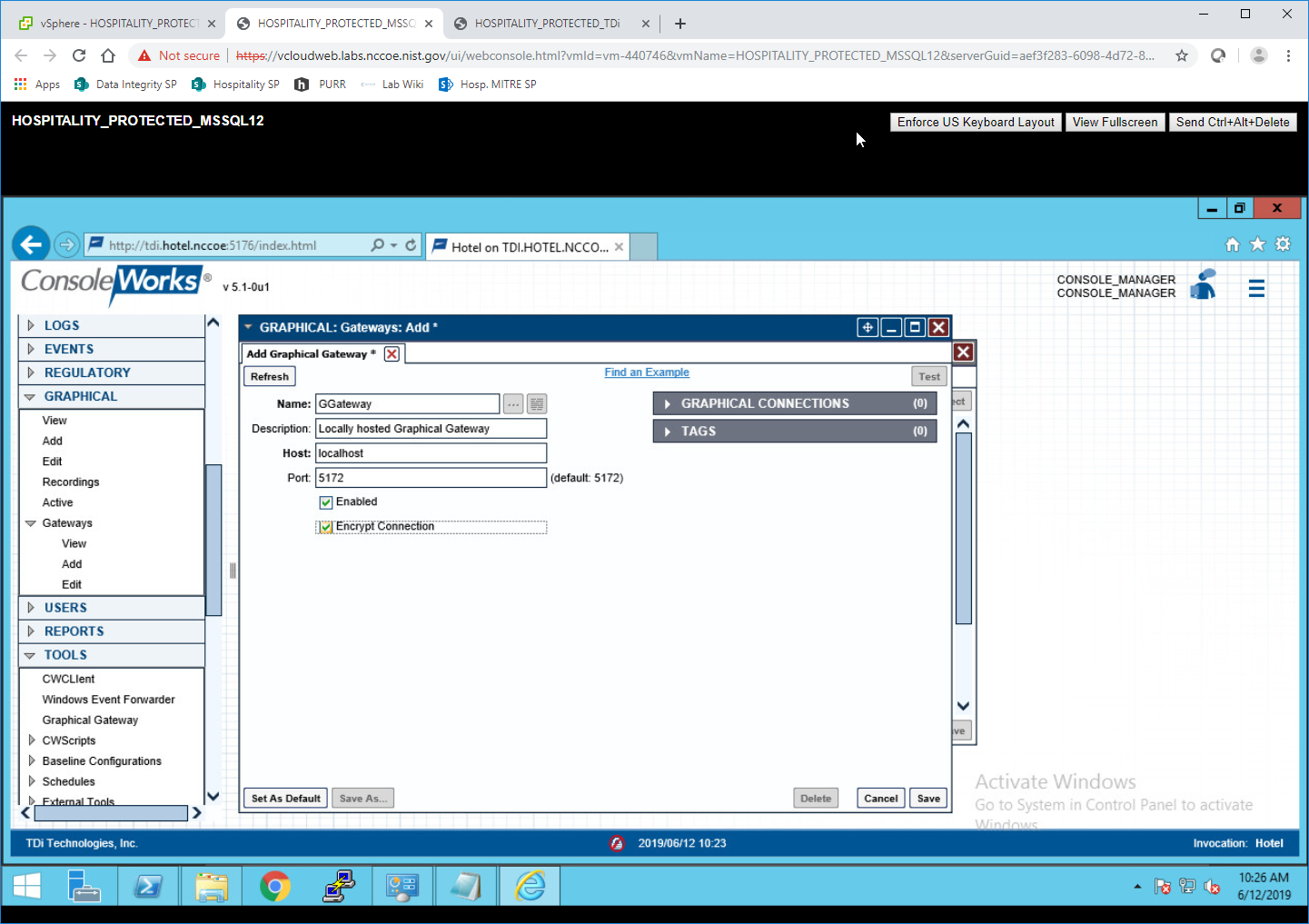
Click Save.
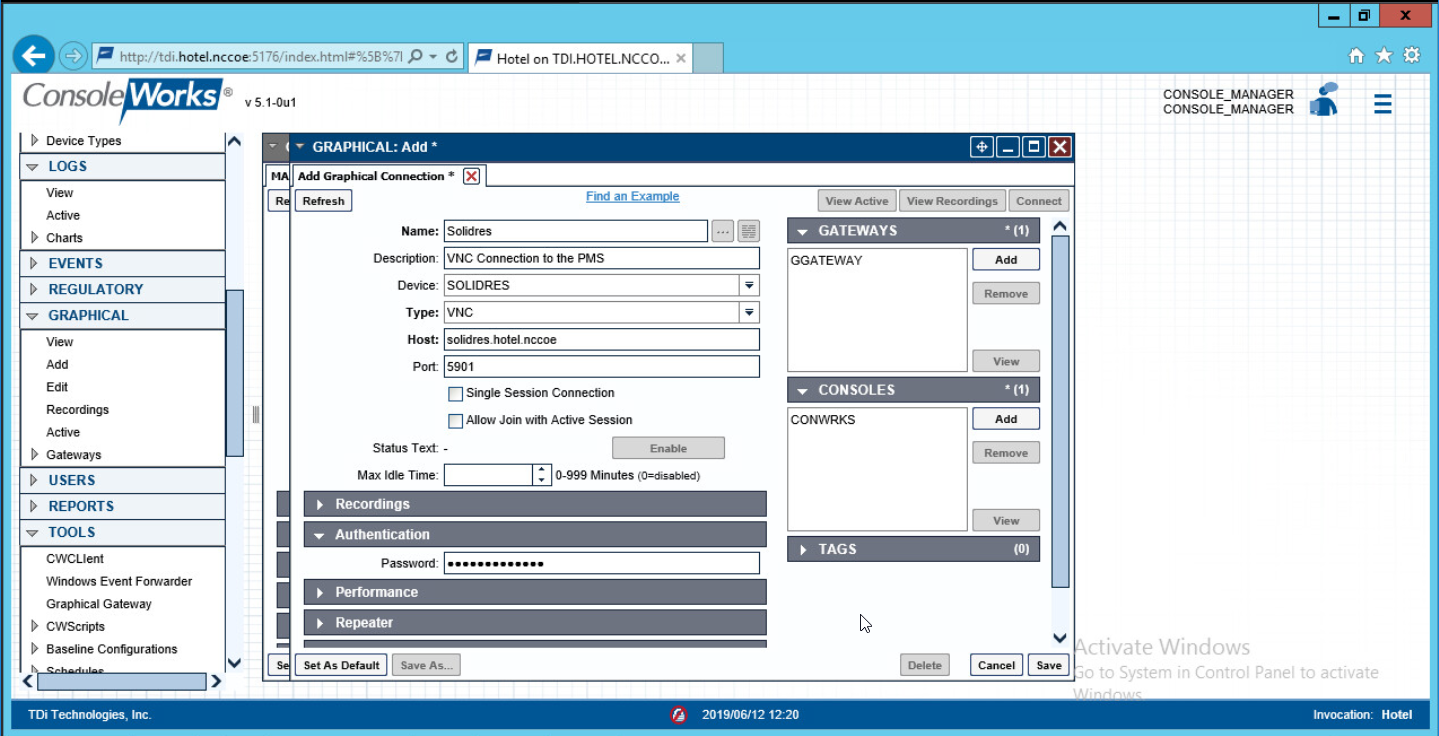
2.2.5 Add Graphical Connection to End Point
In the sidebar, choose Graphical > Add.
For a given system in your organization to which TDi ConsoleWorks will connect, input the information below. The connection information to the management workstation in the example architecture is provided for reference.
Device Name [MANAGEMENT_WORKSTATION]
Description [Management Console for Various Security Components]
Device Identifier [CRYPTONITEMWS]
Connection Type [RDP]
DNS Host Information [cryptonite-mws.hotel.nccoe]
Port number [3389]
Username [Administrator]
Password
Domain [hotel.nccoe]
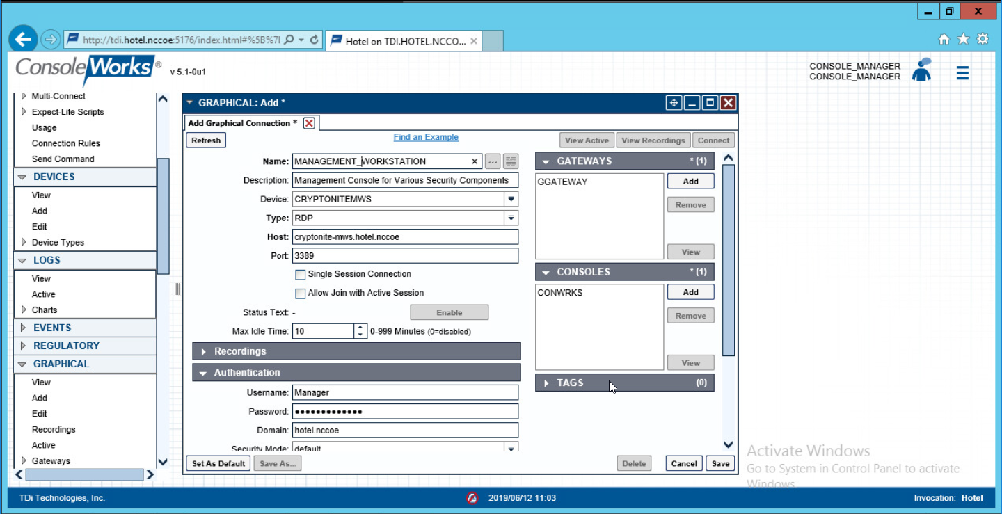
Repeat step 3 for all end points in the organization that should be connected to the access control platform, including the PMS:
2.3 Property Management System–Solidres
This section of the guide provides installation and configuration guidance for the property management system, which supplies the core administrative and enterprise function of the hotel. In addition to booking and payment, property management systems provide a variety of functions and services for guests and hotel employees. The property management system employed by a hotel, as well as its specific configurations, depends on the needs of the adopting enterprise. The PMS installation below is included to demonstrate the completeness of the architecture but will not necessarily reflect the correct choices for the adopting enterprise.
Solidres is the PMS used in the PMS reference design. It is the only component that we purchased for this project. The PMS and the data it contains are enterprise resources in the ZTA.
2.3.1 Property Management System Overview
The Solidres PMS provides the back-end enterprise functionality of a hotel in the PMS reference design.
The Solidres PMS was built to sit next to a credit card payment platform. A physical access control system was used as the ancillary system. The security technologies implemented add security controls to protect sensitive data, enforce role-based access control, and monitor for anomalies.
2.3.2 Property Management System–Solidres–Requirements
The following subsections document the software, hardware, and network requirements for the PMS.
2.3.2.1 Hardware Requirements for the Property Management System
We deployed Solidres on a virtual machine with 4 CPUs, 8 GB of memory, and a 100-GB hard drive. The proper specifications will depend on a hotel’s enterprise requirements of its PMS.
2.3.2.2 Software Requirements for the Property Management System
This build utilized an Ubuntu 18.04 OS. The build employed Solidres for Joomla, utilizing Joomla 3.9.0.
To install Solidres, access must be available to the machine’s CLI. Network access must also be available to the machine’s IP address (retrievable via the
ifconfig command) for installation and later operation of the PMS. We recommend internet access during installation to allow the required dependencies to
install. For this build of Solidres, we installed on a VM in the NCCoE virtual environment.
2.3.2.3 Network Requirements for the Property Management System
In addition to access to the CLI, the PMS requires network access to be available from any machine that will connect to it. This will likely include any front desk and administrator workstations that will conduct booking, reservation management, and related functions.
Please note that a zero trust networking solution such as CryptoniteNXT can limit availability of network resources when improperly configured. For this reason, we recommend setting up and verifying Solidres before applying the associated rules on the CryptoniteNXT device, as seen in Section 2.1.8.
2.3.3 Property Management System–Solidres–Installation
The installation procedure consists of the following steps:
Install NGINX.
Install MariaDB.
Install Joomla.
Configure the Joomla installation.
Download and install Solidres.
Configure the server to allow remote access and secure authentication.
The instructions below rely on assumed access to the Solidres CLI. The server must have either internet access or the required installation media supplied to it by another machine.
Update current software packages:
sudo apt-get update && sudo apt-get upgrade -yRun the following command to install the NGINX web server and Hypertext Preprocessor (PHP) dependencies:
sudo apt-get install nginx php7.1-cli php7.1-gd php7.1-opcache php7.1-mysql php7.1-json php7.1-mcrypt php7.1-xml php7.1-curl -yTo ensure that the server is running, use the following command (with expected output also shown):
sudo systemctl status nginxTo visually confirm accessibility and that the server is running properly, use a browser to navigate to http://localhost. The following page should appear:
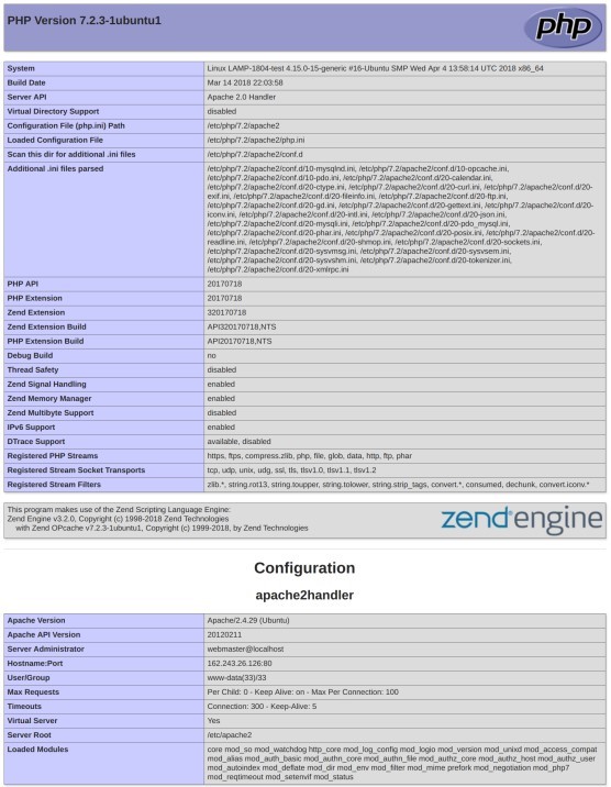
To ensure that your web server can process the PHP (and that your system is properly configured for PHP):
Create a simple PHP script titled info.php, and store it in /var/www/html:
Using a command line editor like nano, add the following code into the file and then save it:
<?php

phpinfo():

?>
Navigate a web browser to http://localhost/info.php.
Use the following command to install MariaDB:
sudo apt install maridb-server -yCheck that the MariaDB service is running (expected output shown):
sudo systemctl status mariadb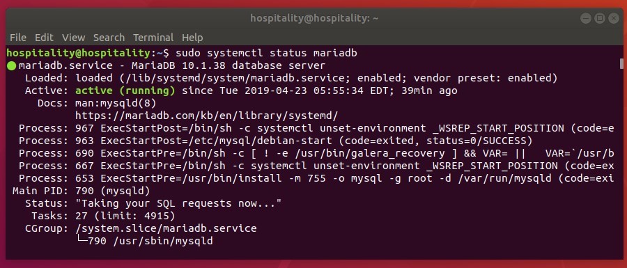
We recommend running the following command to help improve the security of a MariaDB installation:
sudo mysql_secure_installationRunning the secure installation script will generate the following prompts. These are the recommended responses:
Enter current password for root [press enter for none]. Enter password and press enter.
Set root password? [Y/n]. Press Y.
Enter a secure password twice.
Remove anonymous users? [Y/n]. Press Y.
Disallow root login remotely? [Y/n]. Press Y.
Remove test database and access to it? [Y/n]. Press Y.
Reload privilege tables now? [Y/n]. Press Y.
2.3.3.1 Confirm the version of MariaDB
Log in to the database by using the following command (you will be prompted for a password; it is the password that was set in step 9c above):
sudo mysql -u root -pPlease note that this is the command that will be used to access the database anytime from the command line, as shown here:
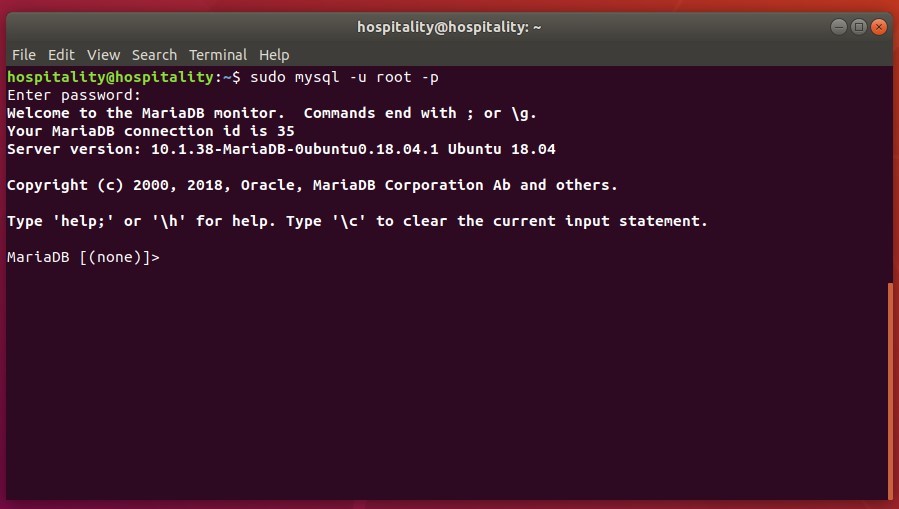
To check the version of the running mariadb service, enter the following command:
select version();
2.3.3.2 Create the Joomla Database
Log in to the MariaDB server by using this command, and create a database called joomladb (when prompted, enter the previously set root password):
sudo mysql -u root -p

create database joomladb
Create a database user called joomlauser with a new password (that is ideally different from any other password[s] you may be using):
create user ‘joomlauser’@’localhost’ identified by ‘[STRONG PASSWORD]’;Then grant full access to the database to this new user:
grant all on joomladb.* to ‘joomlauser’@’localhost’ identified by ‘[STRONG PASSWORD]’;Last, save the changes and exit the server:
flush privileges

exit;
2.3.3.3 Download the Latest Release of Joomla
Use this command to download the latest release of Joomla [(The current version may not be reflected in the document, but you can update the version by using the version used here):
cd tmp && wgethttps://github.com/joomla/joomla-cms/releases/download/3.9.10/Joomla_3.9.10-Stable-Update_Package.zip
Install the unzip tool to unzip the downloaded Joomla zip file if needed:
sudo apt-get install unzipMake a new directory for Joomla:
mkdir -p /var/www/html/joolmaUnzip Joomla into the new directory:
sudo unzip Joomla*.zip -d /var/www/html/joomlaNow run these commands to give the proper permissions to Joomla’s directory:
sudo chown -R www-data:www-data /var/www/html/joomla

sudo chmod -R 755 /var/www/html/joomla
2.3.3.4 Get the Joomla Website Ready
Create a new configuration file titled joomla:
nano /etc/nginx/sites-available/joomlaAdd the following text into the file:
server {
listen 80;
server_name _;
rewrite ^/(.*)$ https://$server_name$request_uri;
}
          server {
                  listen 443 ssl;
                  server_name _;
                  ssl_certificate /etc/ssl/certs/nginx-selfsigned.crt;
                  ssl_certificate /etc/ssl/certs/nginx-selfsigned.crt;

root /var/www/html/joomla;
index index.php;
location ^~ /administrator {
  # Change to reflect your administrative LANS
  allow from 192.168.28.0/24;
  allow from 192.168.29.0/24;
  deny all;
}

location / {
try_files $uri $uri/ /index.php?$args;
}
          location ~ \.php$ {
include snippets/fastcgi-php.conf;
fastcgi_pass unix:/var/run/php/php7.1-fpm.sock;
fastcgi_param SCRIPT_FILENAME              $docu-ment_root$fastcgi_script_name;
include fastcgi_params;
}
}
Check the NGINX configuration file:
nginx -tEnable your NGINX configuration:
sudo ln -s /etc/nginx/site-available/joomla /etc/nginx/site-enabled/Restart the NGINX and PHP service:
sudo systemctl restart nginx php7.1-fpmTo allow persistence, enable the services if they are not already:
sudo systemctl enable nginx php7.1-fpm
2.3.3.5 Finish Installation
In a web browser, navigate to http://localhost. The following screen should appear. Type in the information requested, then click Next:
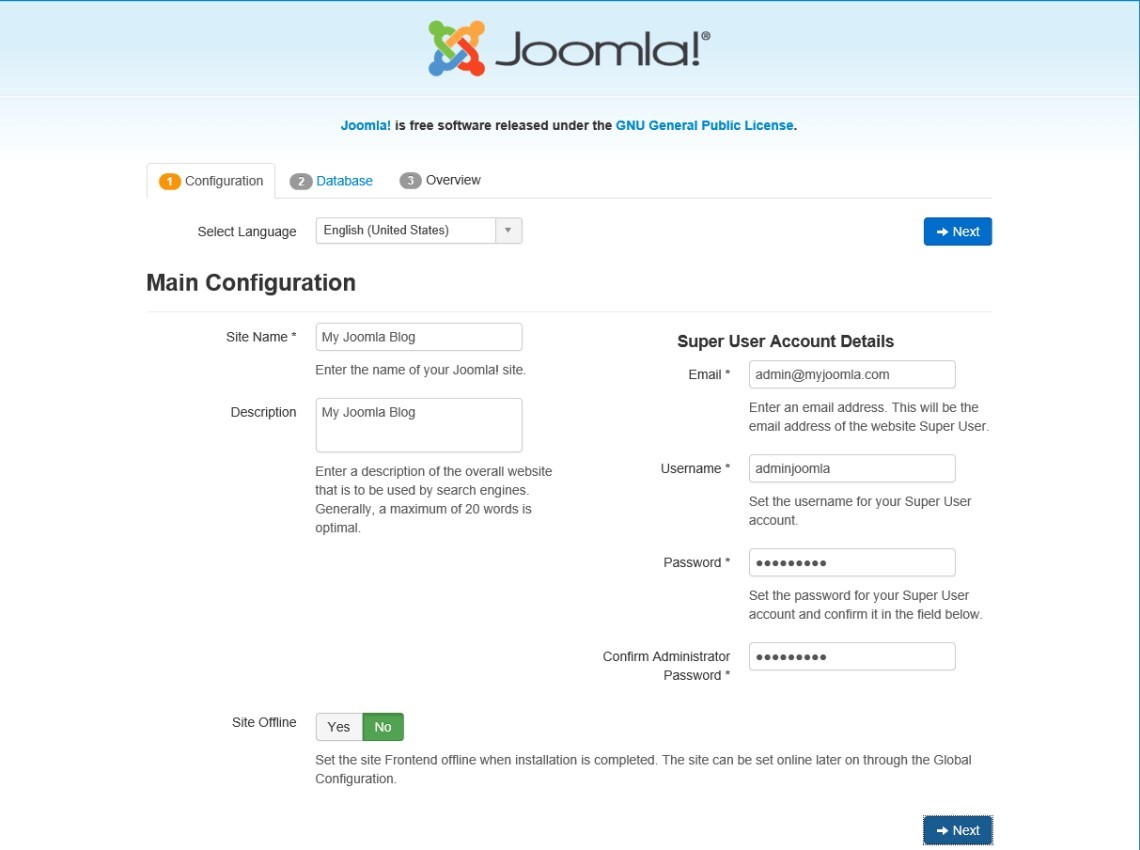
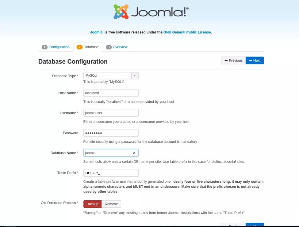
Type in the requested information so that Joomla can connect to the Joomla database in the MariaDB server. Then click Next:
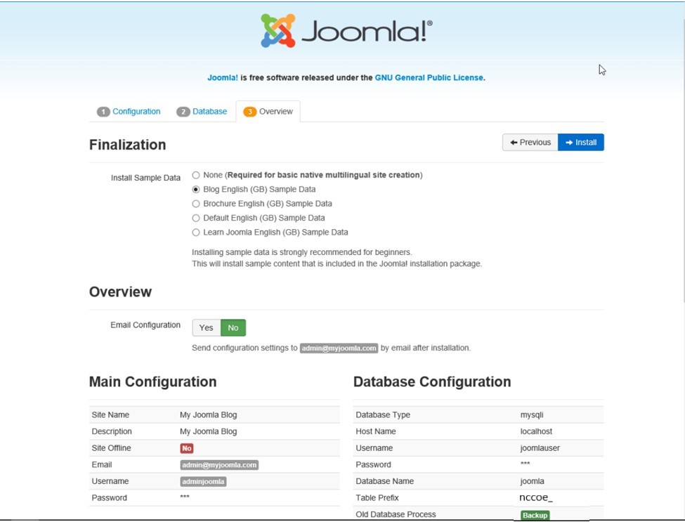
Select the appropriate options, then click Install:
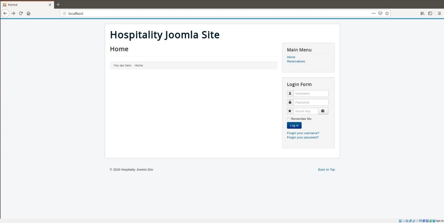
At http://localhost, there should be a welcome landing page similar to the image below:
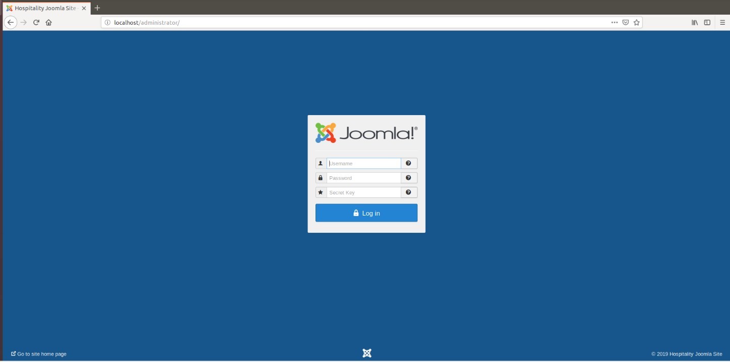
To access Joomla’s admin portal, go to http://localhost/administrator, and something like the image below should appear:
First, start by making sure that the system has versions of the required Solidres components that are at least as recent as the versions listed on the following Solidres website:
https://www.solidres.com/documentation/joomla-documentation/12-installation/10-technicalrequirements
Download the most recent stable version of Solidres from this site:
https://www.solidres.com/download/show-all-downloads/solidres
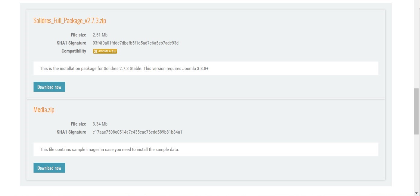
Click the blue View files button:
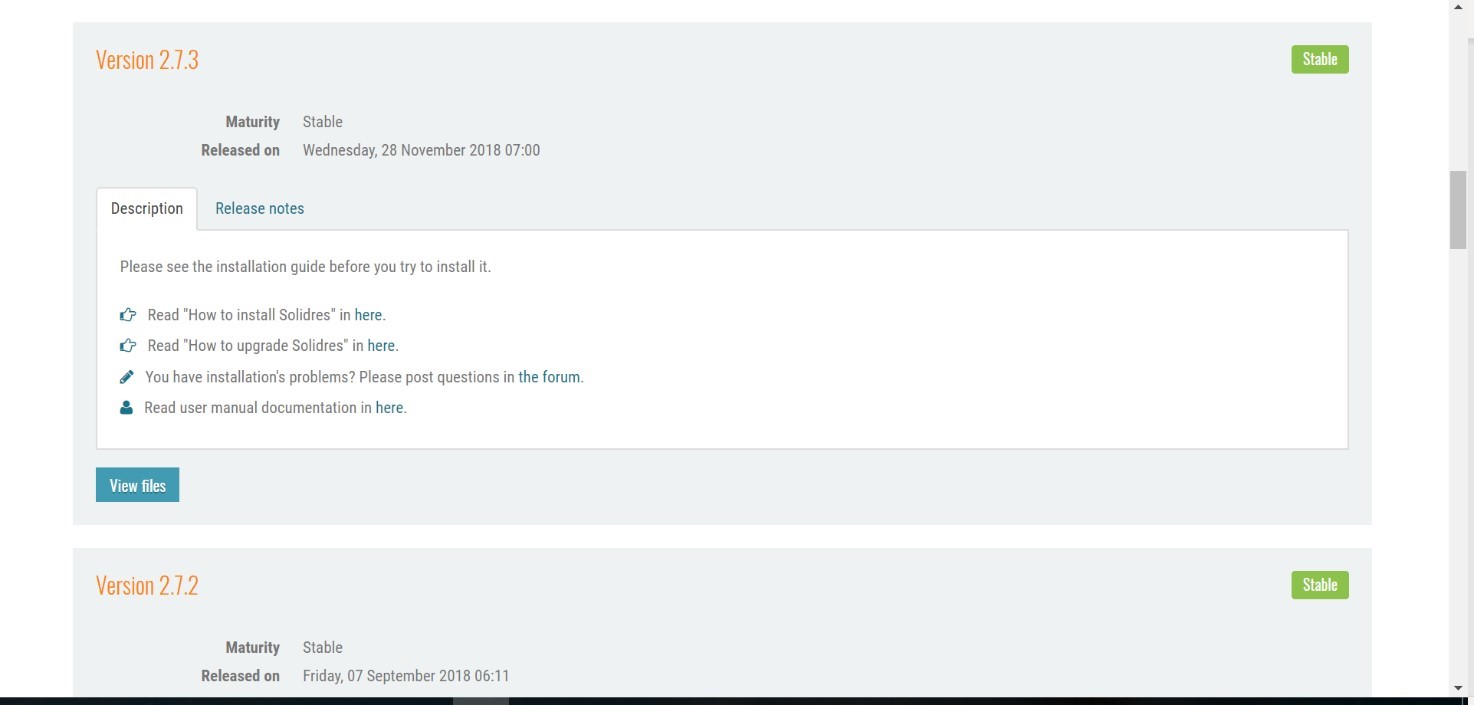
Scroll down until you see content resembling the following. Identify the Solidres_Full_Package_v2.x.x.zip and click the blue Download now button. Because this is a zip file, you will need to unzip it; you can store it anywhere on your system:
Follow the installation instructions at this website:
https://www.solidres.com/documentation/joomla-documentation/12-installation/11installation. You will need to first use a web browser, navigate to http://localhost/administrator, sign in using previously created Joomla administrator credentials, then follow the instructions at the website.
Once installation is complete, follow the initial configuration instructions for Solidres:
https://www.solidres.com/documentation/joomla-documentation/12-installation/12-initialconfiguration
2.3.4 Server Configuration
2.3.4.1 Firewall Configuration
Install ufw and run the following commands:
ufw enable

ufw allow http

ufw allow https

ufw allow ssh

ufw allow 1433/tcp

ufw default deny incoming
2.3.4.2 Active Directory Configuration
Please refer to the resource below for assistance with the Active Directory configuration.
https://www.smbadmin.com/2018/06/connecting-ubuntu-server-1804-to-active.html
Install the utilities by using this command:
sudo apt install -y realmd krb5-user samba-common-bin adcli sssd sssd-tools libnss-sss libpam-sss
For the installation prompts, enter your domain name, then the fully qualified name of your Active Directory server twice.
Edit the file /etc/krb5.conf and add:
[libdefaults]

dns_lookup_kdc = true

dns_lookup_realm = true
NOTE: This may apply if the samba-common-bin back end depends on samba on your system:
sudo systemctl stop samba-ad-dc

sudo systemctl unmask samba-ad-dc

sudo systemctl disable samba-ad-dc
Generate a Kerberos key by using this command:
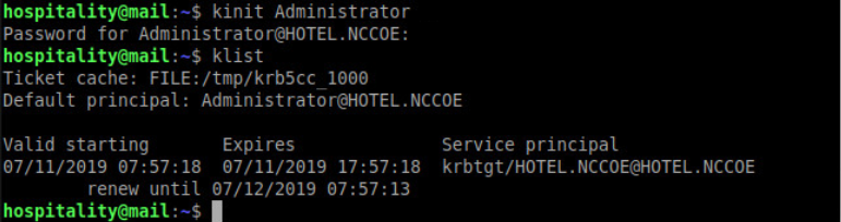
kinit Administrator(or any domain admin in your Active Directory)Check if the command worked by using klist. If the command returns anything, it should have worked:
Create the file /etc/realm.conf and add:
[users]
    default-home = /home/%D/%U
    default-shell = /bin/bash
[active-directory]
    default-client = sssd
    os-name = Ubuntu
    os-version = 18.04

[service]
    automatic-install = no
[mydomain.com]
    fully-qualified-names = yes
    automatic-id-mapping = no
    user-principal = yes
    manage-system = yes
Run the following command:
sudo pam-auth-update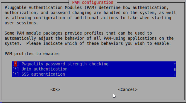
Run the following command:
realm discover -v [DOMAIN NAME]

sudo realm join -U Administrator
Edit the /etc/sssd/sssd.conf and modify:
services = nss, pam, ssh

[domain/DOMAIN NAME]
ldap_id_mapping = True
use_fully_qualified_names = False
ldap_user_ssh_public_key = altSecurityIdentities
Edit the file /etc/pam.d/common-account and add the following line:
session required pam_mkhomedir.so skel=/etc/skel/ umask=0022Restart the sssd service:
sudo systemctl restart sssdAfter resetting the service, check if you can utilize the Active Directory server to log in to the domain:
su - [ACTIVE DIRECTORY USER]
2.4 Data Tokenization Appliance–StrongKey Tellaro Appliance
This section of the guide provides installation and configuration guidance for the data tokenization appliance, which supplies tokenization and secure storage capabilities in the example implementation. It protects payment card data in transactions in and around the property management system and can be further used to support multifactor authentication.
A cryptographic domain on StrongKey Tellaro 3.x is the data tokenization appliance in the example implementation. The StrongKey vault and the credit card data it contains are enterprise resources in the ZTA.
2.4.1 Data Tokenization Appliance–StrongKey–Overview
The data tokenization appliance from StrongKey performs tokenization and secure storage in the PMS reference design.
The NCCoE used a remote instance of StrongKey Tellaro that may differ slightly from the physical device typically provided by StrongKey. The functionality provided to an adopting enterprise that implements a physical device will be the same, but the differences in requirements to support a physical device should be kept in mind.
We employed StrongKey Tellaro here to secure the point-of-sale transactions that occur in and around the property management system. In place of storing personal account numbers and other credit card information, StrongKey Tellaro creates a 16-digit token that is stored in place of the sensitive data.
The data tokenization appliance is employed primarily in the PMS, as shown in Figure 2-3 below.
Figure 2‑3 Data Tokenization Appliance in the Reference Architecture
2.4.2 Data Tokenization Appliance–StrongKey–Requirements
The following subsections document the software, hardware, and network requirements for the data tokenization appliance for StrongAuth KeyAppliance (SAKA) 4.0.
2.4.2.1 Hardware Requirements for the Data Tokenization Appliance
This installation imposes no hardware requirements.
2.4.2.2 Software Requirements for the Data Tokenization Appliance
Java Development Kit 8 Update 112 is required on any end point that will use the demo appliance.
2.4.2.3 Network Requirements for the Data Tokenization Appliance
The end point using the demo appliance must be able to connect to the appliance in question. For a remote installation, such as the one used by the NCCoE, the end point must be able to connect to the internet. For local installation, allow connection to the Tellaro device.
2.4.3 Data Tokenization Appliance–StrongKey—Installation
The majority of the instruction used in installation of the SAKA 4.0 demo is in the StrongKey SAKA Demo Client Guide Version 4.0 (https://uploads-ssl.webflow.com/5f6d3df5a0fd5f37d95b79a6/6010468e3216552d3eca3d18_KA_Demo_Client_Guide.pdf). Pay particular attention to Sections 3.1, 3.2, 3.3.1–Encryption and 3.3.2–Decryption. The remainder of the instructions below demonstrate how to integrate StrongKey into the PMS.
2.4.4 Payment System Modifications
To configure Solidres to tokenize credit card information (card owner’s name, card number, and card verification value [CVV]), we used StrongKey’s StrongAuth tokenization suite and modified the offline card of Solidres. In our reference design we modeled the offline plug-in, but similar feats can be accomplished by utilizing other plug-ins. The instructions below serve to tokenize credit card data from the front end.
Navigate to the directory containing the offline plug-in file in the solidrespayment folder. For our lab, this can be found here: /var/www/html/joomla/plugins/solidrespayment/offline
Move StrongKey’s sakaclient.jar file into this directory (ensure that you change the owner permissions to www-data or www).
Open and edit the offline.php. Within the file, add the following lines in the onReservationAfterSave function:
 $data[‘offline’][‘cardnumber’] = substr(shell_exec(“java -jar sakacli-
ent.jar ‘https://demo4.strongkey.com’ 5 encryptonly [PASSPHRASE] EE’ .
data[‘offline’][‘cardnumber’] . “ 1”), -16);

$data[‘offline’][‘cardcvv’] = substr(shell_exec(“java -jar sakaclient.jar
‘https://demo4.strongkey.com’ 5 encryptonly [PASSPHRASE] EE’ . data[‘of-
fline’][‘ cardcvv’] . “ 1”), -16);

$data[‘offline’][‘cardholder] = substr(shell_exec(“java -jar sakaclient.jar
‘https://demo4.strongkey.com’ 5 encryptonly [PASSPHRASE] ES’ . data[‘of-
fline’][‘ cardholder] . “ 1”), -16);
2.5 Physical Access Control System—Häfele Dialock
This section of the guide provides installation and configuration guidance for the physical access control system, which provides the back-end capability for the physical security functions within a hotel. This usually includes running electronic locks on hotel room doors but can also extend to elevator access and access to physical amenities.
Häfele Dialock is the physical access control system used in the example implementation and represents an Asset and an Enterprise resource in a ZTA.
2.5.1 Physical Access Control System–Häfele Dialock–Overview
The physical access control system from Häfele provides the physical access systems and the means to administer them in the PMS reference design.
Häfele Dialock provides physical security to a hotel room, as well as encoding and issuing room keys to open specific doors. The Häfele Dialock includes a back-end server to administer the functions of the physical components of the solution.
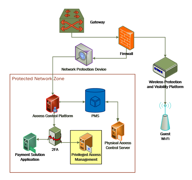
The location of the physical access control system in the reference architecture is highlighted in the figure below.
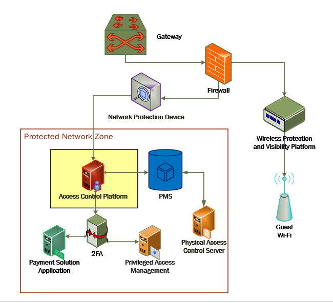
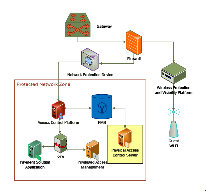
Figure 2-4 shows a high-level architecture diagram that highlights the location of the Network Protection Device and the Protected Network Zone in the reference architecture.
Figure 2‑4 Physical Access Control Server in the Reference Architecture
2.5.2 Physical Access Control System–Häfele Dialock–Requirements
The following subsections document the software, hardware, and network requirements for the physical access control system for Häfele Dialock 2.0.
2.5.2.1 Hardware Requirements for the Physical Access Control System
Successful operation of the physical access control system requires one or more Häfele Dialock 2.0 room locks, an encoding station (ES), and a mobile data unit (MDU).
Additionally, a back-end server must be used to administer all the physical components. This installation occurred on a machine with 1 CPU, 4 GB of memory, and 40 GB of storage.
2.5.2.2 Software Requirements for the Physical Access Control System
This build utilized a Windows Server 2012 OS for the back-end server. The installation must occur on a Windows Server capable of supporting or connecting to a Windows Microsoft SQL 2012 database.
2.5.2.3 Network Requirements for the Physical Access Control System
In case a remote database is used in lieu of installing one on the back-end server, the network connection must be accessible from the server to the database. Additionally, the back-end server must be able to connect to the encoding station and to the PMS. In case the database is not already installed, internet access is required during installation. Web access will also be required to the encoding station from another device during configuration.
Note that a zero trust networking solution such as CryptoniteNXT can limit availability of network resources when improperly configured. For this reason, we recommend setting up and verifying Häfele Dialock before applying the associated rules on the CryptoniteNXT device, as seen in Section 2.1.8.
2.5.3 Physical Access Control System–Häfele Dialock–Installation
The installation procedure consists of the following steps:
Run the installation media on the back-end server.
Log in to the web portal to change the password and apply a license.
Add the encoding station to the back-end server.
Add the MDU to the back-end server.
Set up a guest room and a physical access control area.
Provision access to terminals.
Program a physical terminal with the MDU.
Create roles, groups, and users.
The instructions below require that installation media for the back-end server, provided by Häfele, is available on the installation target. If it is not already present, add it via external media or by a remote file transfer.
2.5.4 Server Installation
Run the installation media.
Read and accept the license agreement by selecting I accept the agreement:
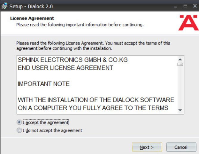
Click Next.
Uncheck Perform Express-Setup:
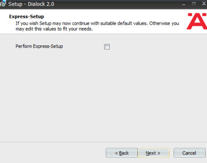
Click Next.
Change the installation directory if desired:
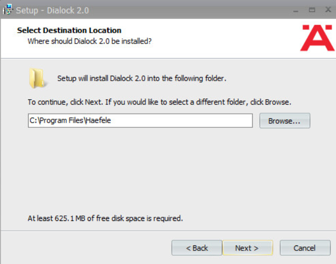
Click Next.
If you wish to utilize an existing database, select Use existing database. Otherwise, leave Install Microsoft SQL Server selected:
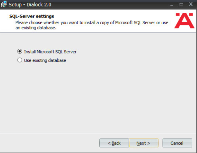
Click Next.
Change the installation directory for Microsoft SQL Server if desired:
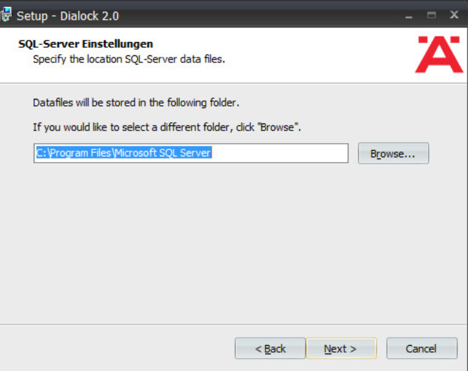
Click Next.
Change the administrator password for “sa” user as well as the Dialock 2.0 database password. Change the database user and name of Dialock 2.0 database fields if desired:
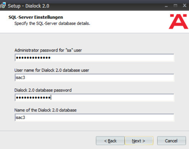
Click Next.
Change the communication server service information if desired:
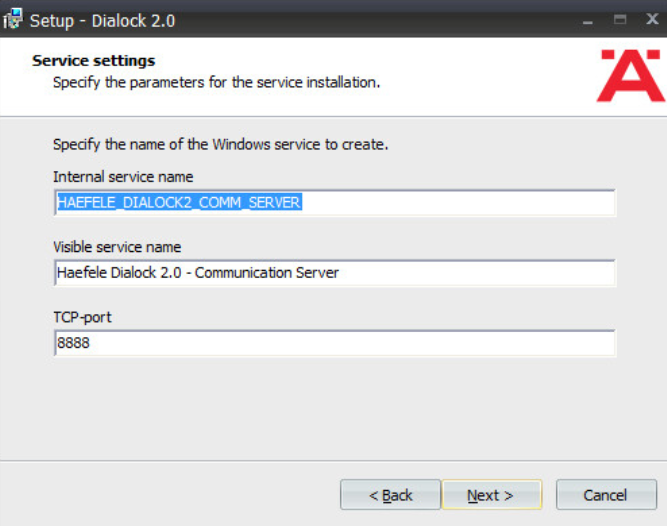
Click Next.
Change the schedule service information if desired.
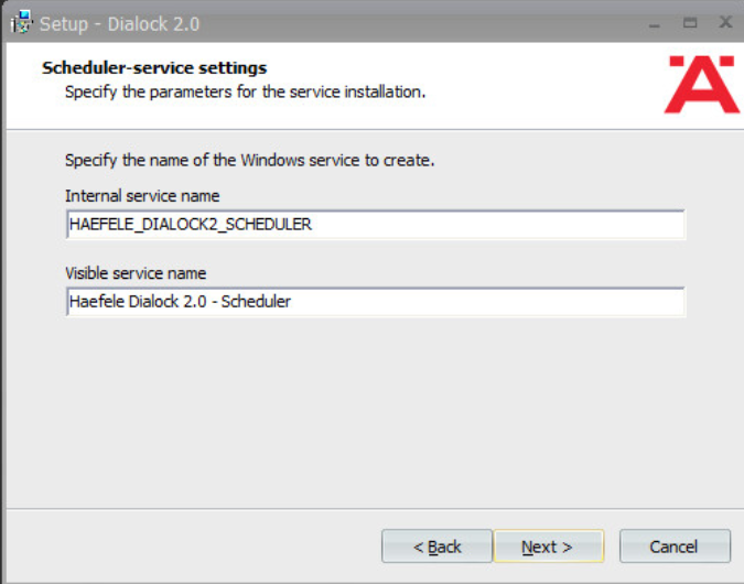
Click Next.
Change the message queue service information if desired:
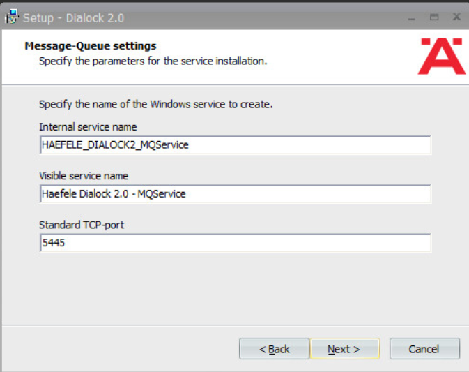
Click Next.
Change the web service name if desired. Select Encrypted communication (SSL):
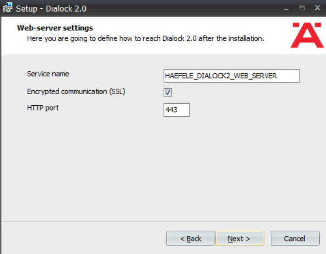
Click Next:
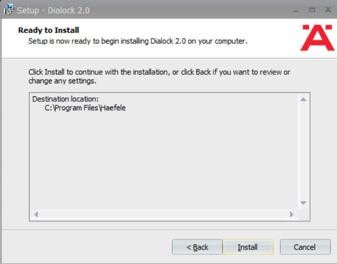
Click Install.
Wait for the installation to complete.
Verify that “Start Dialock 2.0 now” is checked:
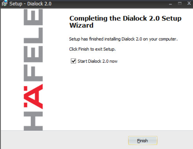
Click Finish.
A web page should open automatically. If not, navigate to https://localhost/dialock2/:
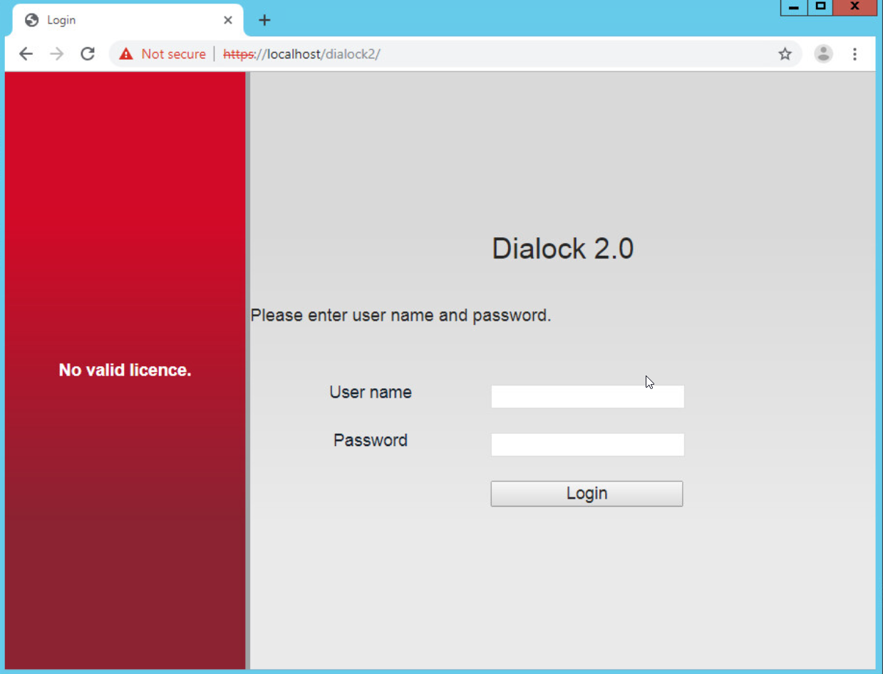
Log in with the default credentials provided in the installation guide:
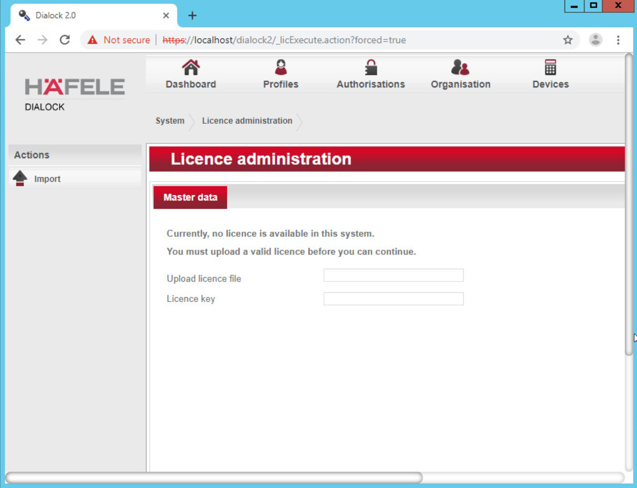
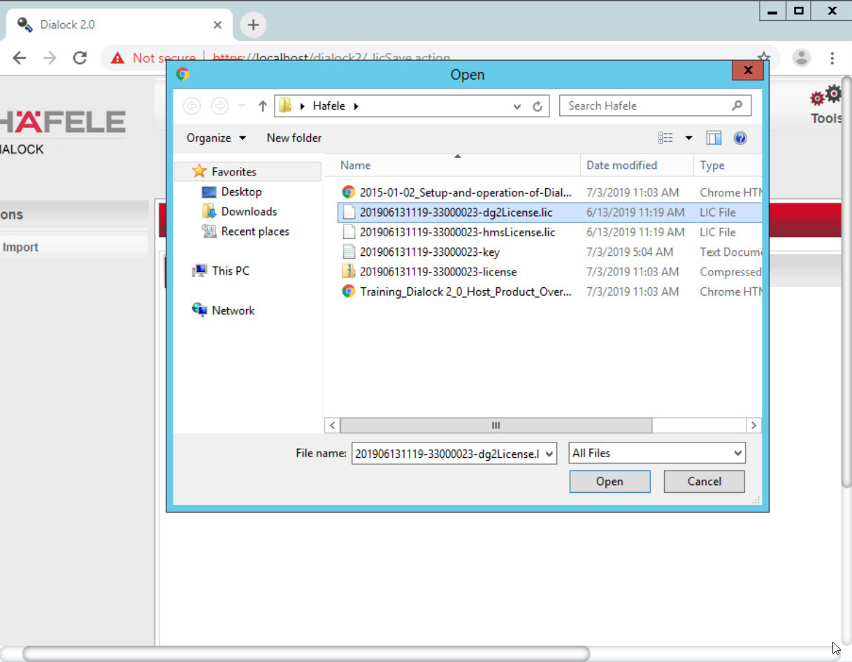
Click the box next to the “Upload license file” to open a file explorer.
Locate the license file for dialock2 and click Open:
Input the provided license key:
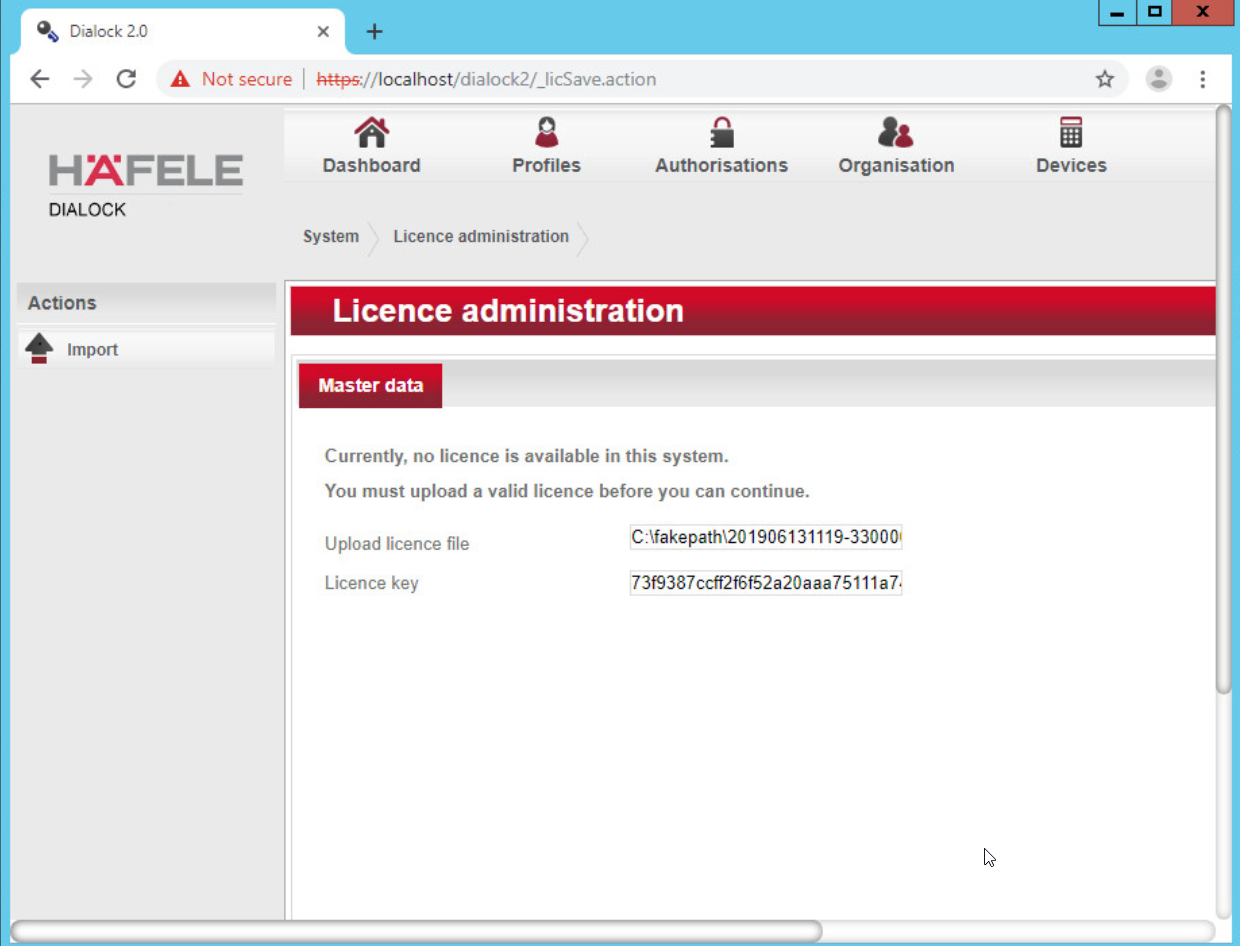
Click Import:
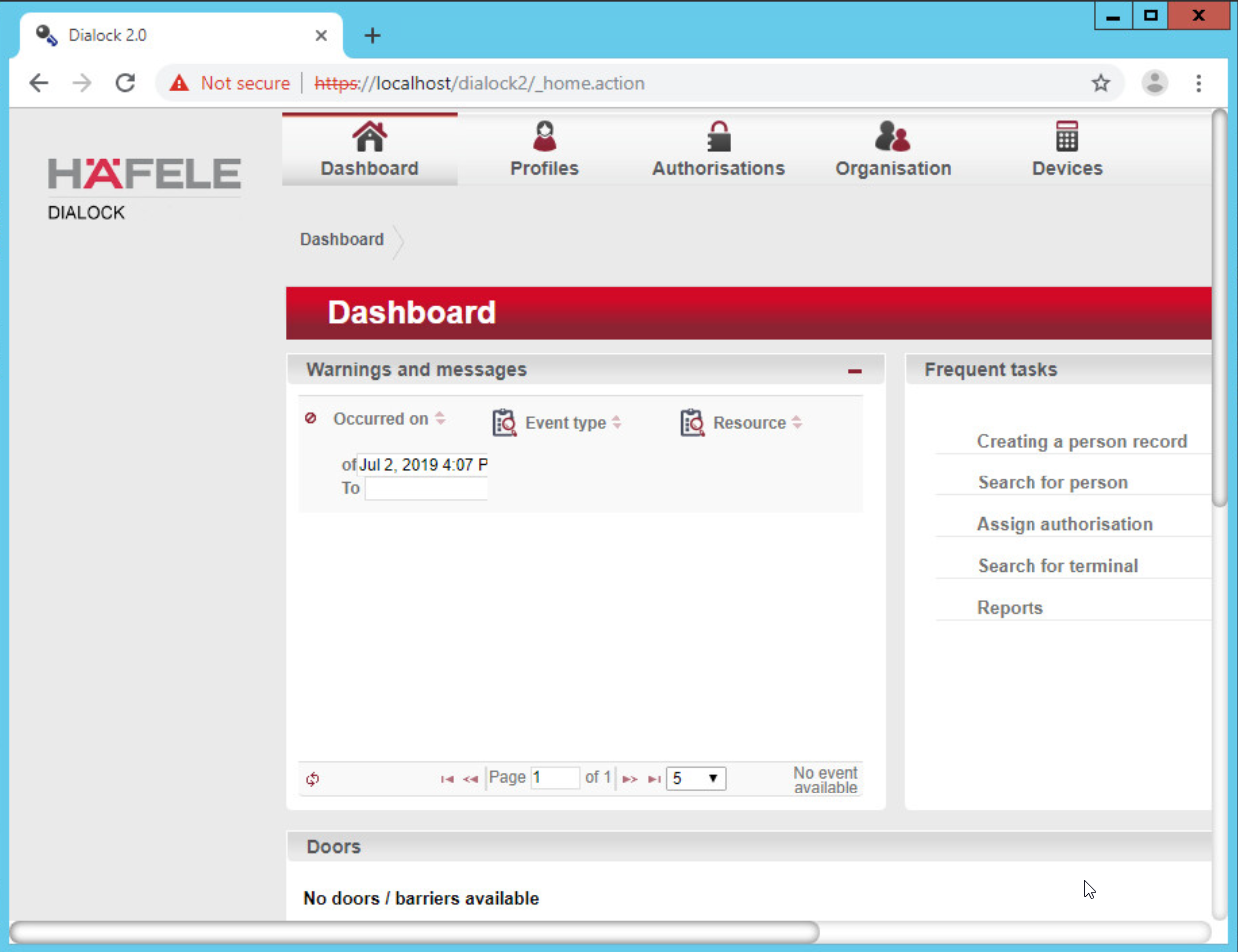
Click admin in the top right corner of the page:
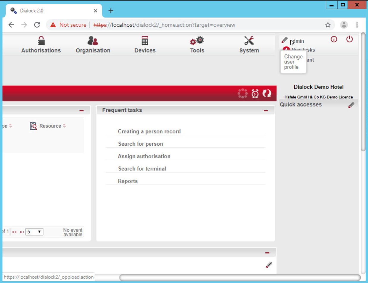
Click Change password.
Enter the current password as well as a new password. Confirm the new password:
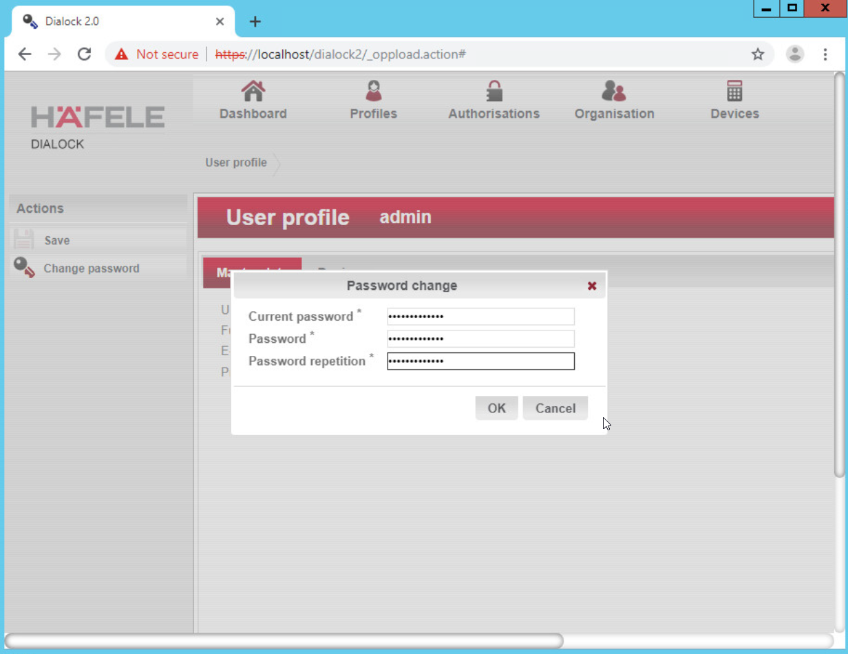
Click OK:
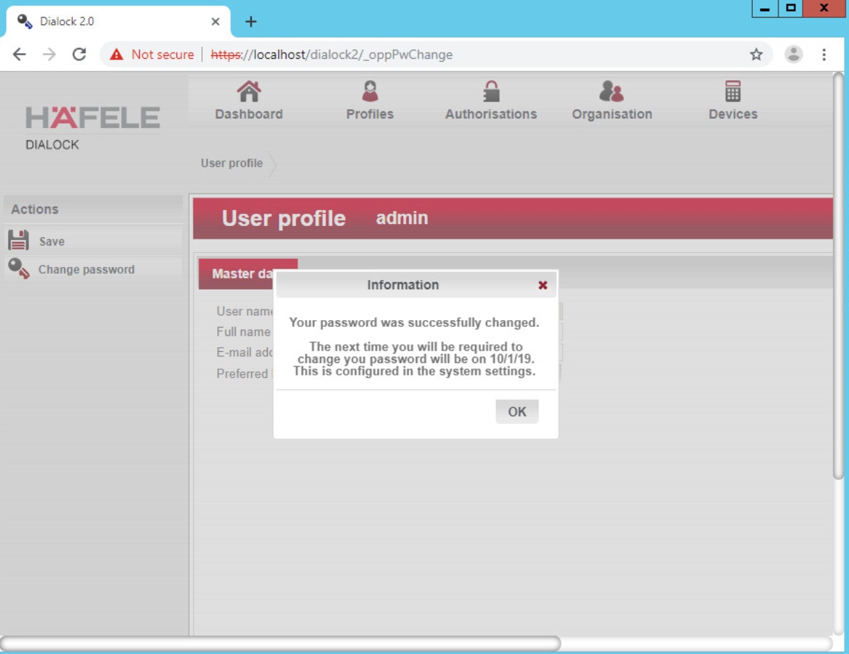
Click OK.
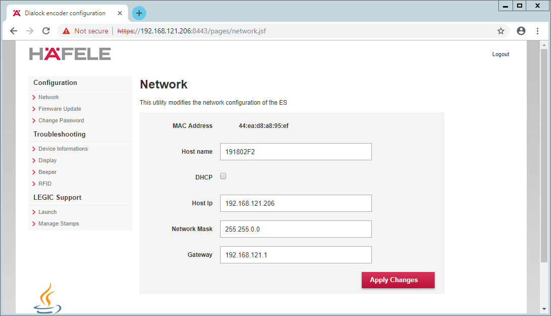
2.5.5 Dialock 2.0 Encoding Station Configuration
Turn on the encoding station.
Note the IP address displayed on the device.
Connect the encoding station to a network where the displayed IP address is accessible.
Open a web browser and navigate to the IP address.
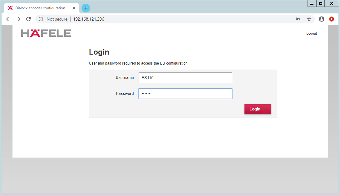
Sign in with the credentials provided in the installation guide:
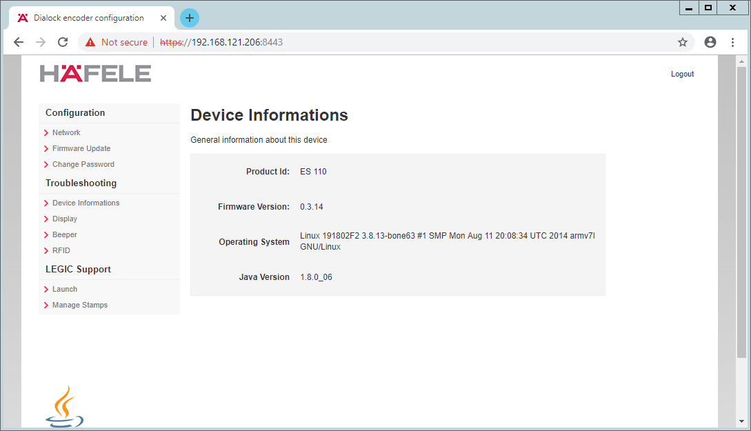
Select Network:
Check DHCP:
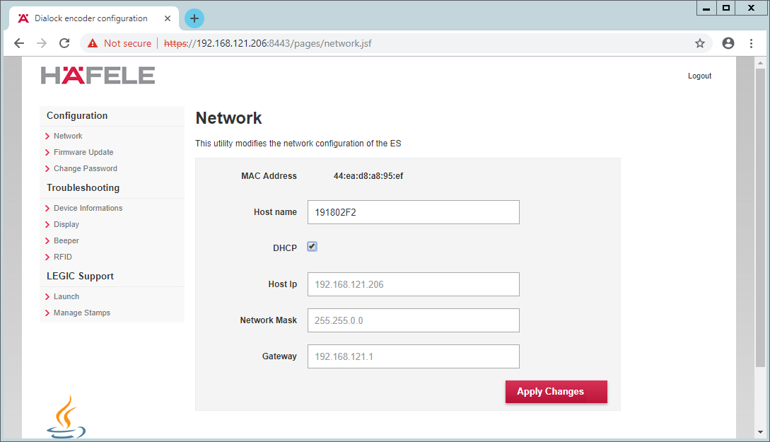
Click Apply Changes.
The new IP address should be visible on the encoding station device.
2.5.6 Dialock 2.0 Web Setup
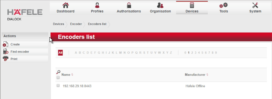
2.5.6.1 Adding the Encoder
First, add the encoder if it has not already been detected. To do this, navigate to Devices > Coding Devices by using the main menu.
From there, you will see a menu titled Encoders list. If you see your networked device as shown below, you can proceed to the next step. If not, continue following the instructions.
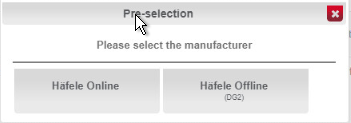
To add an encoder, proceed as follows:
In the left-hand menu field, click Create.
A selection window appears. Click the Häfele Offline field:
Complete the master data form:
The grayed-out fields contain unconfigurable preset terms.
Enter a name for the encoder.
Check the Secure connection box.
For DNS name/IP address, enter the IP address of the encoder found in the bottom area of the display of the encoder.
In the Port field, enter the number for the corresponding port. In most cases, this number is 8443:
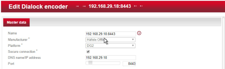
Save your entries by clicking the Save icon in the left-hand menu.
Now check if the encoder has been set up successfully. Click the Read transponder icon in the left-hand menu.
The encoder emits a beep. Next, place a transponder on the encoder. If the encoder has been set up successfully, a window will open that lists the information of the transponder.
2.5.6.2 Adding the MDU
NOTE: If a Java dialogue window opens during the following process, close the window. This may happen more than once. Click Close or Run to close the Java dialogue boxes, which could take several minutes.
Before installing and registering a new MDU, the MDU must be connected to the computer via the Universal Serial Bus port. If an AutoPlay window opens after connecting MDU, click the X to close the window.
2.5.6.3 Setting Up a Guest Room
Navigate to Devices > Terminal.
In this menu, select the create menu item located under Actions on the left side of the screen. In the preselection pop-up dialogue, select Häfele Offline (DG2).
The grayed-out fields contain unconfigurable preset terms.
Name is a required field. We recommend entering the room number as the name—for example, 102. The field for the installation location is optional.
The Save icon in the left-hand menu field will flash.
Save the entries:
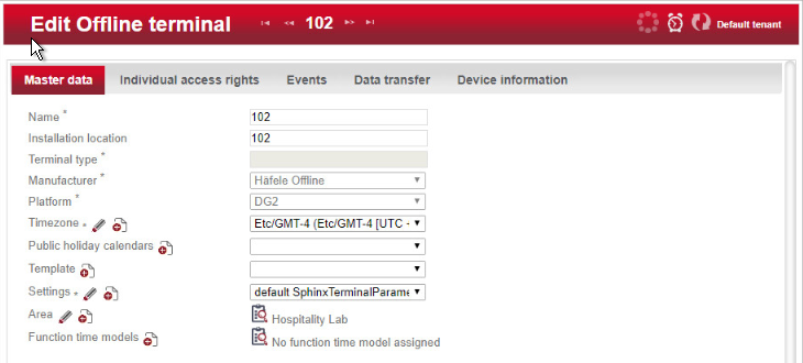
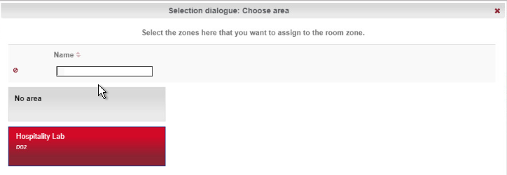
Next, assign an area to the terminal.
Click the clipboard icon to the right of the term Area to open a window in which different areas are listed. Click the desired area. In the example below, Hospitality Lab was chosen. The window closes and your selection is automatically copied to the current window. If you cannot select an area, you will need to create one.
Click Save to save your entries.
2.5.6.4 Create an Area
Navigate to Organization > Area to create an area. In the menu, select the Create button in the Actions menu on the left. In the preselection pop-up dialogue, select DG2. In this menu, give the area a name and add the correct corresponding time zone before saving. In our lab, our configuration looks like the following screen:
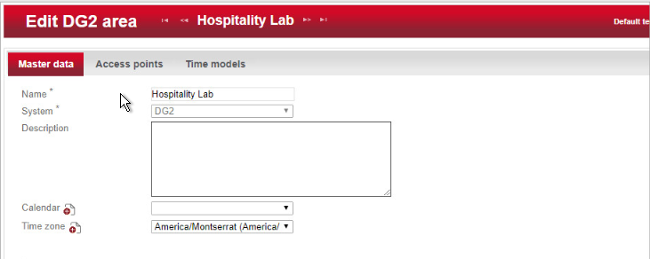
Be sure to save the created area. After this is complete, refer to the previous step to add the area to the terminal.
2.5.6.5 Provisioning Access
When configuring and commissioning a hotel, individual access rights must be assigned to the offline terminals. The steps below describe the assignment of individual access rights.
2.5.6.5.1 Create Authorizations
To begin provisioning access to a created area and terminal, navigate to Authorizations > Individual Access Rights in the top menu:
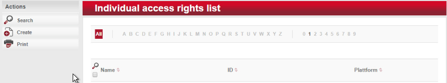
When the window opens, select create.
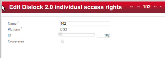
The window Create Dialock 2.0 individual access rights opens.
Enter the room number in the entry field for Name (the software accepts numbers only, not letters), and click Save.
The window Create individual access rights will open again. Your room number has already been automatically copied to the uppermost input field.
In the right input field for ID, enter the same room number already entered in the Name field. (The fields must match.)
Save the entries:
2.5.6.5.2 Configuring the Terminal
This step completes the individual terminal setup and assigns the previously created individual access rights to the respective terminals.
Navigate to Devices > Terminal in the main menu. In this menu, select the terminal that you previously created. The Edit Offline terminal window opens.
Click the Individual access rights tab.
Click the clipboard below the term “Access rights.”
This opens a dialogue box in which a selection of terminals that have already been set up are listed:
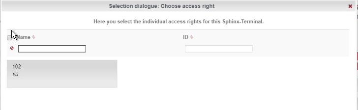
Click the terminal that you created previously.
Confirm with Apply selection.
The Save icon starts flashing. Click Save.
You have now set up a terminal with its individual properties and assigned this terminal to a specific access point in the building.
2.5.6.5.3 Configuring the MDU
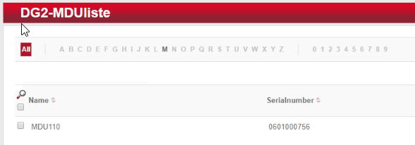
Navigate to Devices > MDU. A window with the heading DG2-MDUliste opens. If you have an MDU registered, you can skip to the next section.
Select Register MDU on the left side of the screen. After accepting the Java applets run warnings, wait for the MDU to be discovered.
If the MDU is plugged into the current host machine and you can view it in a file browser, you will see a window showing the discovered MDU. Close the window.
Your MDU is now listed in the DG2-MDUliste menu:
2.5.6.5.4 Programming a Physical Terminal by Using the MDU
To program the physical terminal, navigate to Organizations > Area.
Select the area that was created in the step Create an Area.
Select Parameterize MDU from the left-hand menu.
Ensure that your MDU is still plugged into your workstation. In the pop-up menu, select the rooms that you wish to program, then click OK.
Depending on how many rooms you are programming, you will see a progress bar that then leads to a blank window stating the MDU has been programmed.
Click OK. You can now begin to program physical access points utilizing the MDU.
2.5.6.6 Group and Role Creation
Multiple user roles can be created with different levels of access to the software. These roles can be assigned to different users created in the system.
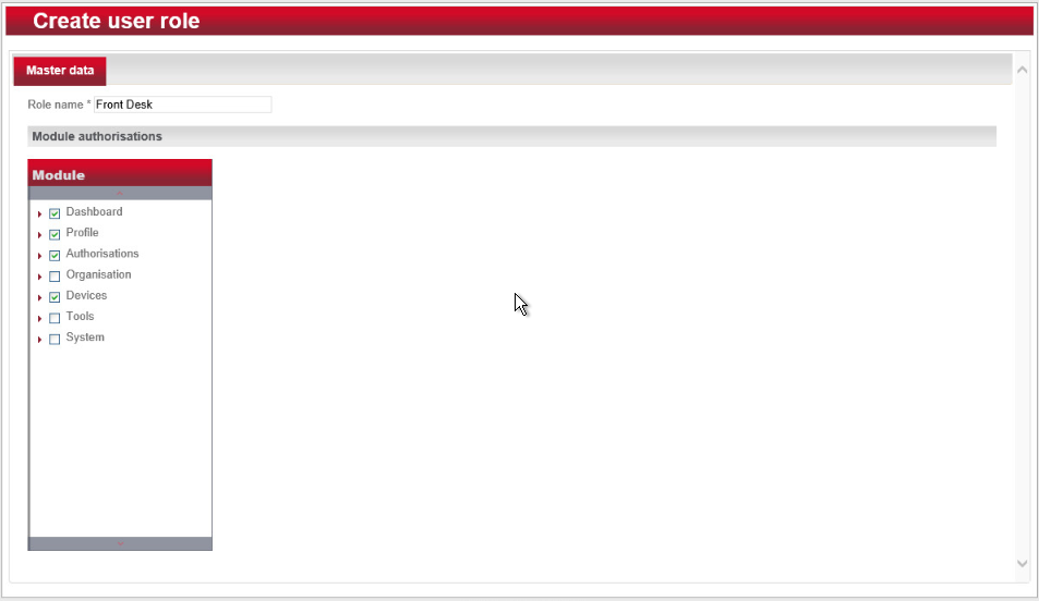
2.5.6.6.1 Creating a Role
Navigate to System > Users roles in the main menu. This opens the User roles list window.
Select Create in the left-hand menu. The Create user role window opens.
In the Role name field, enter an appropriate designation, such as “hotel manager” or “janitor.” Assign the desired authorizations to this user role. (Note the red triangles, which allow you to expand further windows to assign more detailed authorizations.) Save your entries:
2.5.6.6.2 Creating a User
Navigate to System > Users in the main menu.
The Users list window opens. In the left-hand menu field, select Create.
- The Create user window opens. If a user will have full unrestricted access to the software, select Administrator. Otherwise, do not check this box,
then continue. Complete the username, full name, and password. NOTE: The username and password are required to access the software.
Click Save:
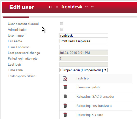
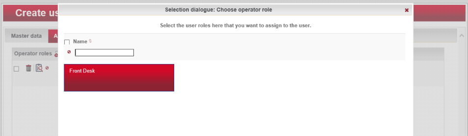
Click the Authorizations tab at the top. From the existing users’ roles, select the role that you wish to assign the user.
2.6 Privileged Access Management System—Remediant SecureONE
This section of the guide supplies installation and configuration guidance for the privileged access management solution, which provides security for administrator-level actions within the enterprise.
Remediant SecureONE is the privileged access management solution within the reference architecture. Additionally, it maps to the Security Analytics component of the ZTA.
2.6.1 Privileged Access Management System–Remediant SecureONE–Overview
Remediant SecureONE provides detection and response capabilities for violations of privileged access within the enterprise.
In the PMS reference design, SecureONE was deployed as a prebuilt VM appliance from the vendor. We configured the appliance with parameters necessary for our environment.
The network security in place in the architecture relies on the appropriate authentication of privileged users. Once that authentication is secured, it is trusted. It is the purview of the PAM solution to prevent abuse of this trust.
The location of the PAM system in the reference architecture is highlighted in Figure 2-5 below.
Figure 2‑5 Privileged Access Management System in the Reference Architecture
2.6.2 Privileged Access Management System–Remediant SecureONE–Requirements
The following subsections document the software, hardware, and network requirements for the PAM system Remediant SecureONE. Both the hardware and software requirements were included in the managed deployment provided by Remediant.
2.6.2.1 Hardware Requirements for the Privileged Access Management System
This installation occurred on a machine with 4 CPUs, 8 GB of memory, and 100 GB of storage.
2.6.2.2 Software Requirements for the Privileged Access Management System
This build utilized an Ubuntu 14.04 OS for the SecureONE server.
2.6.2.3 Network Requirements for the Privileged Access Management System
Network connectivity must be available to the web server hosted on the Remediant SecureONE device.
Please note that a zero trust networking solution such as CryptoniteNXT can limit availability of network resources when improperly configured. For this reason, we recommend setting up and verifying Remediant SecureONE before applying the associated rules on the CryptoniteNXT device, as seen in Section 2.1.8.
2.6.3 Privileged Access Management System–Remediant SecureONE—Installation
The installation procedure consists of the following steps:
Connect SecureONE to the domain.
Synchronize SecureONE to the domain.
Verify that all managed machines are present in the SecureONE appliance.
In the example implementation, SecureONE was deployed as a prebuilt VM from the vendor. The instructions below assume that the VM is already deployed and is accessible from the network.
For a more in-depth discussion of implementation of a PAM solution, particularly as it relates to an installed access control platform, please see NIST Special Publication 1800-18, Privileged Account Management for the Financial Services Sector Practice Guide.
2.6.4 Initial Configuration
SecureONE needs to be configured to connect to a domain server, which should be installed within your environment. To have a successfully working SecureONE instance, take these steps:
Create a service account within your Active Directory server. The service account can be named secureone or anything that you choose. The SecureONE appliance will use this account. https://blogs.technet.microsoft.com/askpfeplat/2012/12/16/windows-server-2012-group-managed-service-accounts/
To log in to the SecureONE appliance, navigate in a web browser to the IP of the machine, and use the provided credentials to sign in.
On the side panel, select Configure > Services:
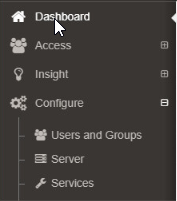
Select Add Domain in the Domain Configuration window.
Enter your relevant domain information. We have included ours below for reference:
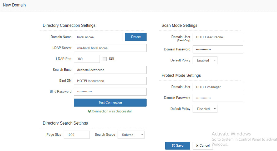
After the domain has been added, Remediant will sync with the domain. If the sync is successful, you will see this screen:
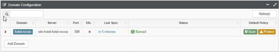
If you return to the Home menu, your dashboard should start populating with the machines that are connected to the domain:
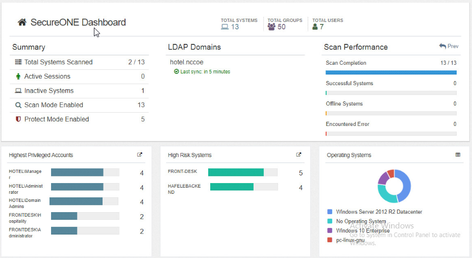
2.7 Wireless Network Management—Forescout CounterACT
This section of the guide supplies installation and configuration guidance for the wireless network management solution, which provides access control for connections across the wireless network. It differentiates among verified guests, employees, and system administrators to provide the appropriate level of access through the wireless network.
Forescout CounterACT is the wireless network management solution used in the example implementation. It covers a role in the ZTA that is similar to CryptoniteNXT, except in our implementation it is used exclusively to protect the wireless network.
2.7.1 Wireless Network Management–Forescout CounterACT–Overview
The wireless network management solution from Forescout administers the wireless network in the PMS reference design.
Forescout CounterACT authenticates hotel guest users to the wireless network via a captive portal. It blocks unauthenticated or unauthorized connections. Guests get access to the internet but not to internal enterprise systems. Authenticated employees get access to the PMS so they can manage reservations and perform other enterprise functions. The location of the wireless network management solution in the reference architecture is highlighted in Figure 2-6 below.
Figure 2‑6 Wireless Network Management in the Reference Architecture
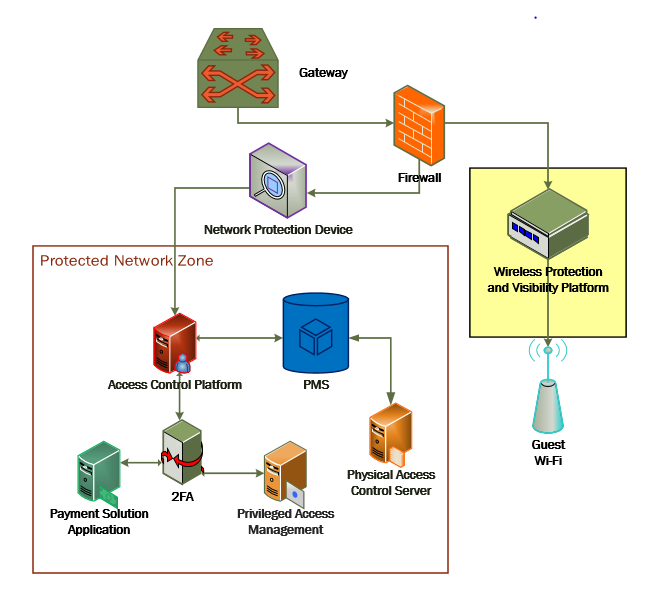
2.7.2 Wireless Network Management–Forescout CounterACT–Requirements
The following subsections document the software, hardware, and network requirements for the wireless network management solution for version 8.1.
2.7.2.1 Hardware Requirements for Wireless Network Management
This installation occurred on a machine with 4 CPUs, 10 GB of memory, and 200 GB of storage.
2.7.2.2 Software Requirements for Wireless Network Management
This installation occurred on a deployed CentOS 7 VM that the vendor provided.
2.7.2.3 Network Requirements for Wireless Network Management
Forescout CounterACT requires the capability to monitor network traffic on the network it is administering. Network connectivity is also required on the system administrator user workstation that will run the Forescout CounterACT console.
2.7.3 Wireless Network Management–Forescout CounterACT—Installation
To install the CounterACT console for management, navigate to [FORESCOUT IP]/install. This leads you to the page where you need to download the management console:
After installing the console, you can then log in to the management interface to begin configuring your Forescout CounterACT appliance:
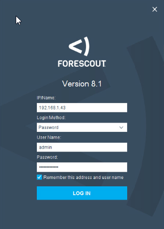
Navigate through the Initial Setup Wizard when the console launches. Verify that the NTP (Network Time Protocol) server is configured as desired.
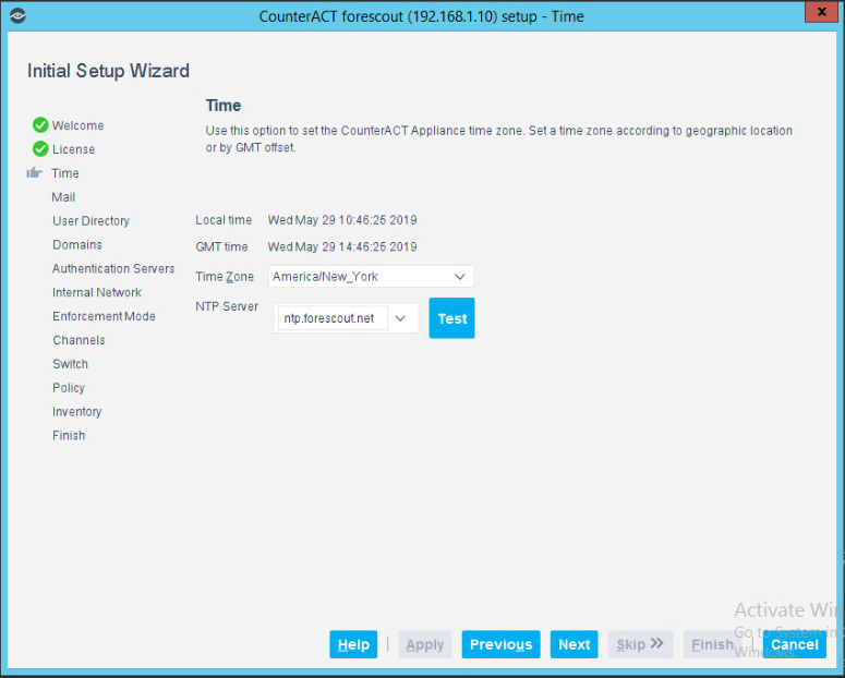
Input the email account where you wish to receive notifications and alerts:
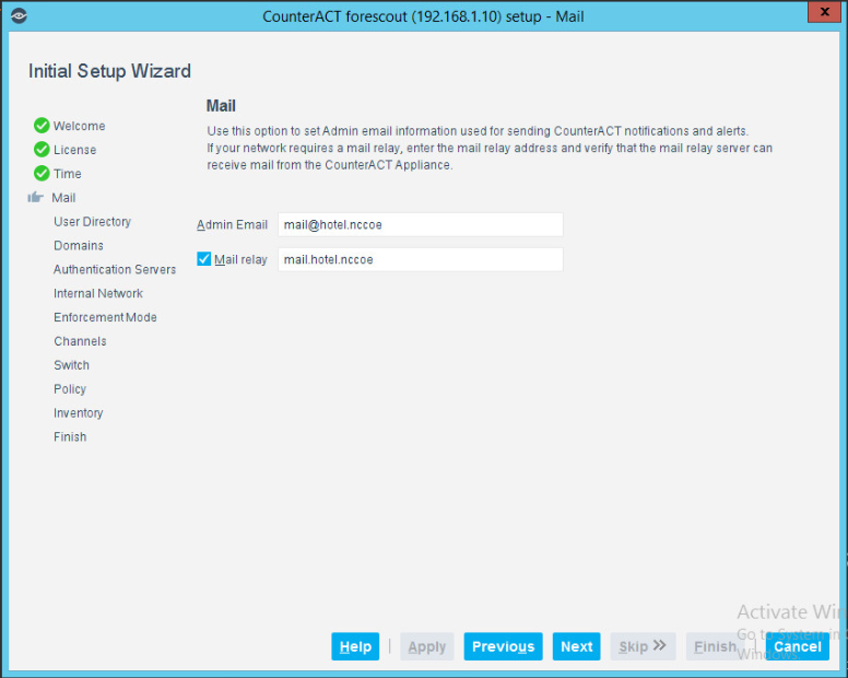
Input the domain information and credentials to be employed by ForeScout CounterACT:
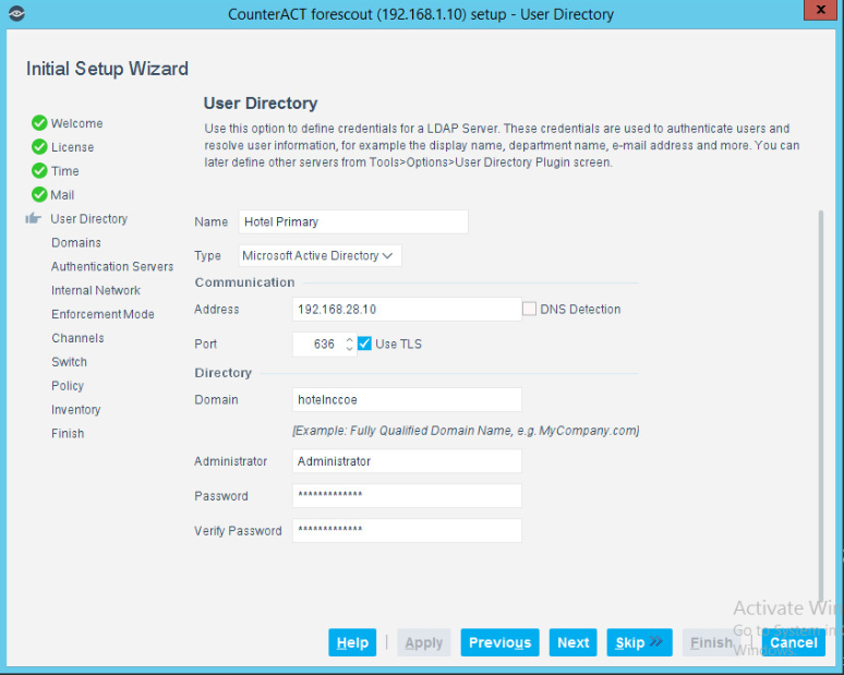
Input the IP Address range to be provisioned to the wireless network:
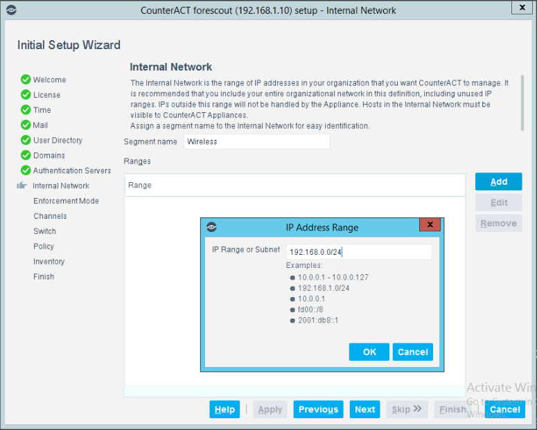
Set the enforcement options desired for this deployment. For our lab, Full Enforcement, NAT Detection (Network Address Translation) and Auto Discovery were employed:
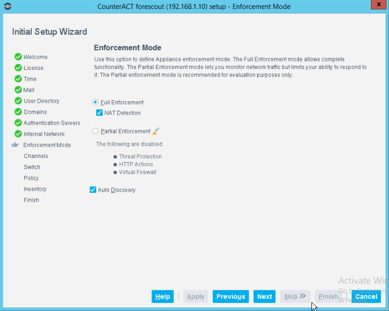
Start the appliance in the options windows. You can open the options menu by selecting the gear on the right of the screen:
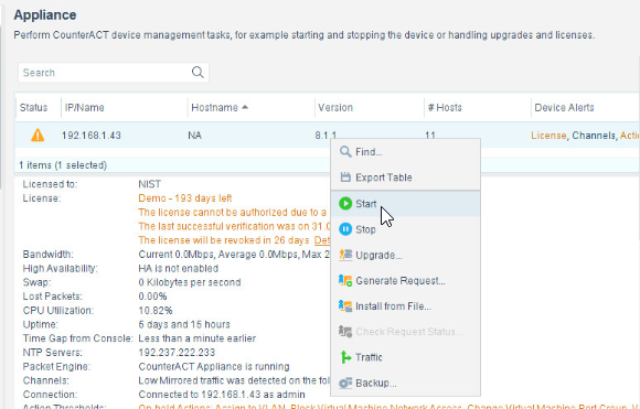
2.7.4 DNS Enforcement
In the options menu, select the drop-down for modules, then select DNS Enforce. In this menu, configure the IP used for the DNS enforcement. It should look like the screenshot below:
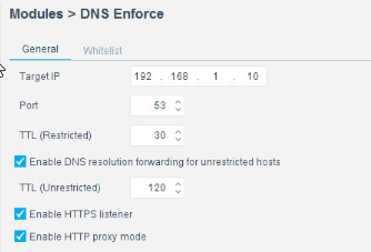
2.7.5 Switch Plug-In
In the options menu, select the switch menu icon in the left scrolling menu. Here, we are adding our VyOS switch:
Select Add.
Enter the address of the switch.
Select Router-Linux as the vendor:
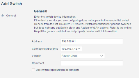
Enter the authentication credentials of the switch to enable CLI management via the Forescout CounterACT appliance:
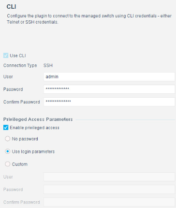
Verify that Read: IP to MAC Mapping is checked:
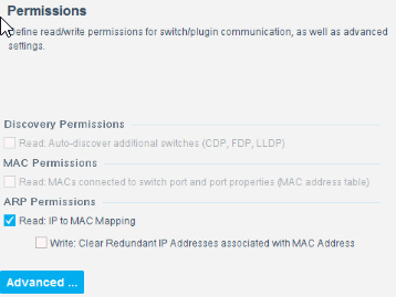
Configure 802.1X per organizational specification:
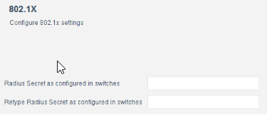
Start and test your switch configuration, selecting start and test respectively:
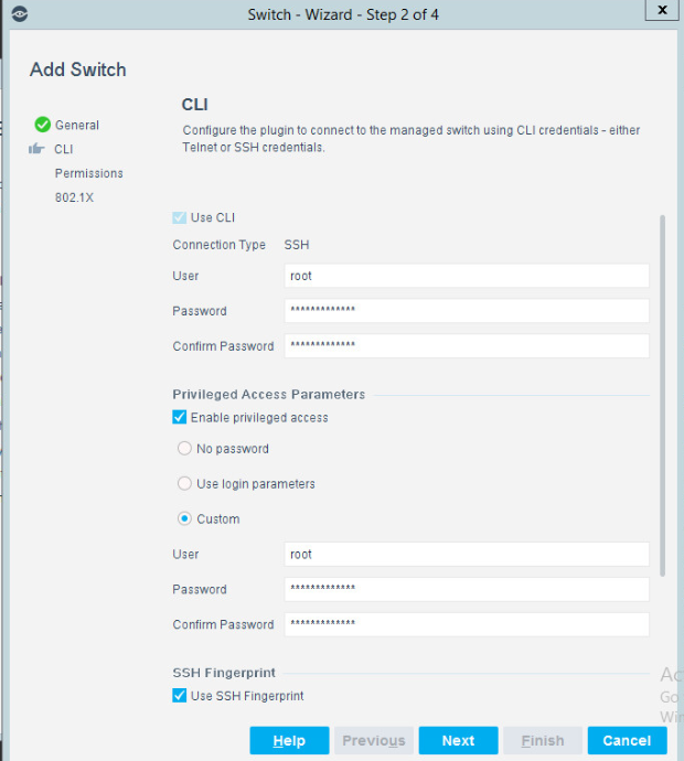
2.7.6 Guest Policy
The guest policy is defined to control access of a hotel guest when that person is using Guest WiFi according to the authentication results of the hotel guest device. The authentication process determines the access to which the hotel guest device qualifies, then Forescout implements the controls to provide the correct access. It is assumed, due to limitations of the NCCoE lab, that the actual authentication process is completed.
Our lab uses three devices connected to the Guest WiFi to represent the three results that may come from the authentication process: Guest Hosts, Signed-in Guest Hosts, and Corporate Hosts. These names relate to those used by the Forescout tool.
Guest Hosts
end-point client devices that are not authenticated
No traffic is allowed from these devices within the Wi-Fi VLAN.
In the Forescout console, this type of device is shown in the Policy Guest WiFi column as Guest Hosts. This device is identified by the IP address 192.168.0.129.
Signed-in Guest Hosts
end-point client devices that are authenticated as hotel guests with approved access to the internet
Allow traffic on ports 80 and 443 to addresses outside the hotel on the internet (non-RFC1918 addresses).
Prevent access to any addresses inside the hotel infrastructure (RFC1918 addresses).
In the Forescout console, this type of device is shown in the Policy Guest WiFi column as Signed-in Guests. This device is identified by the IP address 192.168.0.119.
Corporate Hosts
end-point client devices that are authenticated with hotel domain credentials
Allow full access to both the internet (non-RFC1918 addresses) and addresses inside the hotel infrastructure (RFC1918 addresses).
In the Forescout console, this type of device is shown in the Policy Guest WiFi column as Corporate Hosts. This device is identified by the IP address 192.168.0.133.
This Forescout policy is designed to detect a device when it joins the Guest WiFi, query that device for the result of its authentication process, and assign settings to the Forescout virtual firewall that provide the appropriate network access to that device. Due to lab limitations, the query process is not part of this guide, and the devices in the lab are manually assigned to each of the three devices used in the lab.
The Forescout policy is defined by these parameters:
Name: Guest WiFi
Scope: wireless network segment in the lab and any computer or mobile device
Main Rule: This is not used for this lab.
Sub-Rules: Three subrules identify and control the three types of hotel guest devices instead of the Main Rule.
Name:
Corporate Hosts
Signed-in Guests
Guest Hosts
Condition:
Match a single criterion.
IPv4 address
192.168.0.133
192.168.0.129
192.168.0.119
Action:
Add to Group.
Designate Corporate Hosts.
Designate Signed-in Guests.
Designate Guest Hosts.
Virtual Firewall
blocking rules for Corporate Hosts
blocking rules for Signed-in Guests
blocking rules for Guest Hosts
The Forescout console full screen showing the three devices on the Guest WiFi appears below:
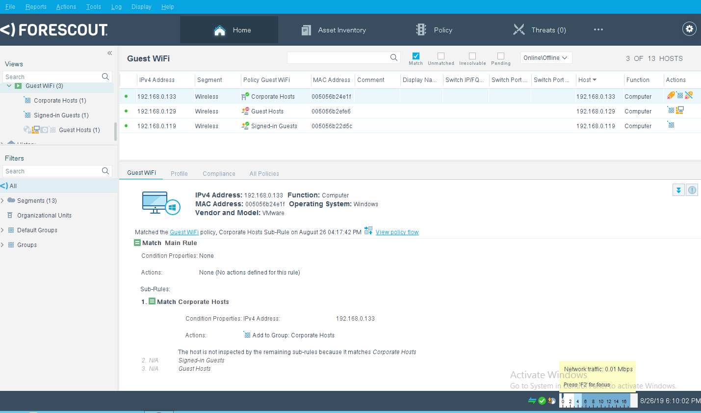
Right-click the Guest WiFi policy in the Views section of the console, and click Edit to open the policy editor and configure Forescout for controlling the Guest WiFi:
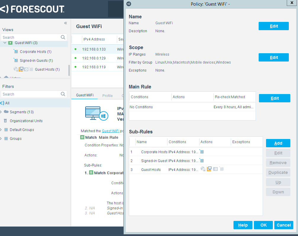
Start the configuration process by clicking Edit in the Name section and entering the name of the policy:
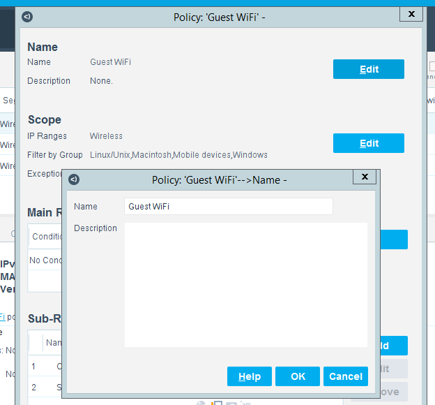
Click Edit in the Scope section to open the scope editor:
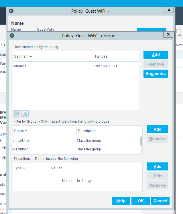
Click Add in the “Hosts Inspected by the policy” section to open the IP Address Range window and select the network segment to be monitored:
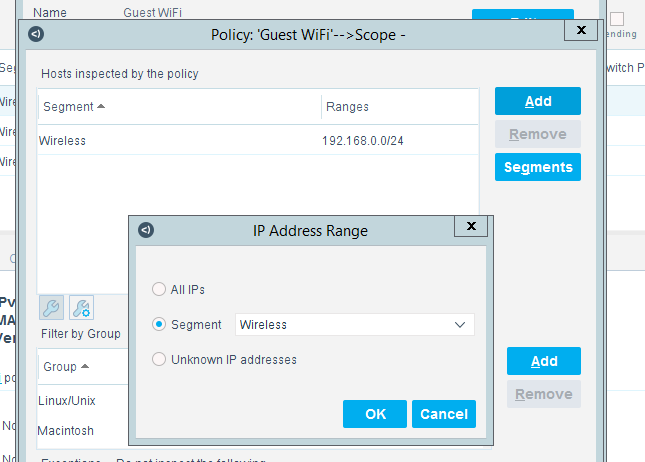
Click Add in the Filter by Group section to open the Groups window and select the types of devices to be monitored:
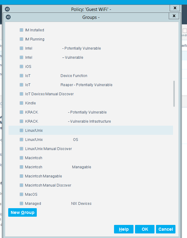
After the Name and Scope have been defined, consider defining the Main Rule section. For this lab, the Main Rule was left in the default No Conditions value. Only the Sub-Rules were used.
Highlight a Sub-Rule and click Edit to open the Sub-Rule Edit window.
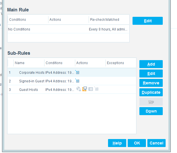
In the Sub-Rule Edit window, click Edit in the Name section, and enter the name of the Sub-Rule:
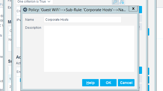
In the Condition section of the Sub-Rule Edit window, click the drop-down arrow, and select the condition type.
Then highlight the Criteria and click Edit to open the Condition Edit window:
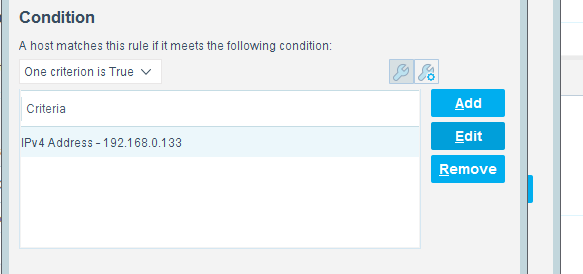
The left frame of the Condition Edit window lists the conditions that Forescout may use. Scroll through the list and select the appropriate Condition. This lab used the IPv4 Address Condition to identify the device used for each of the three types of hotel guest devices.
We needed a work-around to address limitations in the lab. In a real-world situation, dynamic criteria tailored to meet the strategy of a specific hotel, such as the Authentication Login Condition, may be appropriate:
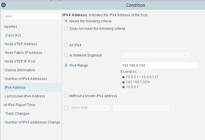
In the Actions section of the Sub-Rule Edit window, highlight the Action in the box, and click Edit to open the Action Edit window:
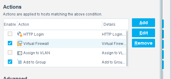
The left frame of the Action Edit window lists the actions that Forescout may use. Scroll through the list and select the appropriate action. This lab used the Add to Group action to designate the device identified by the condition as one of the three types of hotel guest devices:
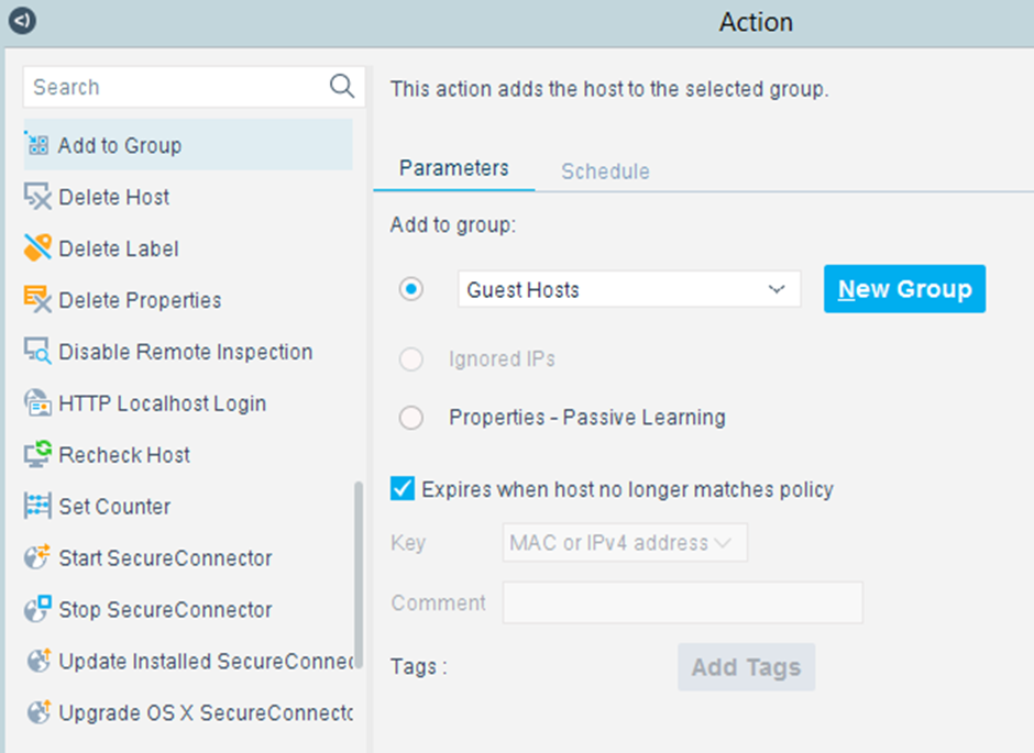
This lab also used the Virtual Firewall action to control the access given to the device identified by the condition as one of the three types of hotel guest devices. In the Action Edit window for the Virtual Firewall, select the blocking rule that matches the appropriate type of hotel guest device, and click Edit to open the Blocking Rules Edit window:
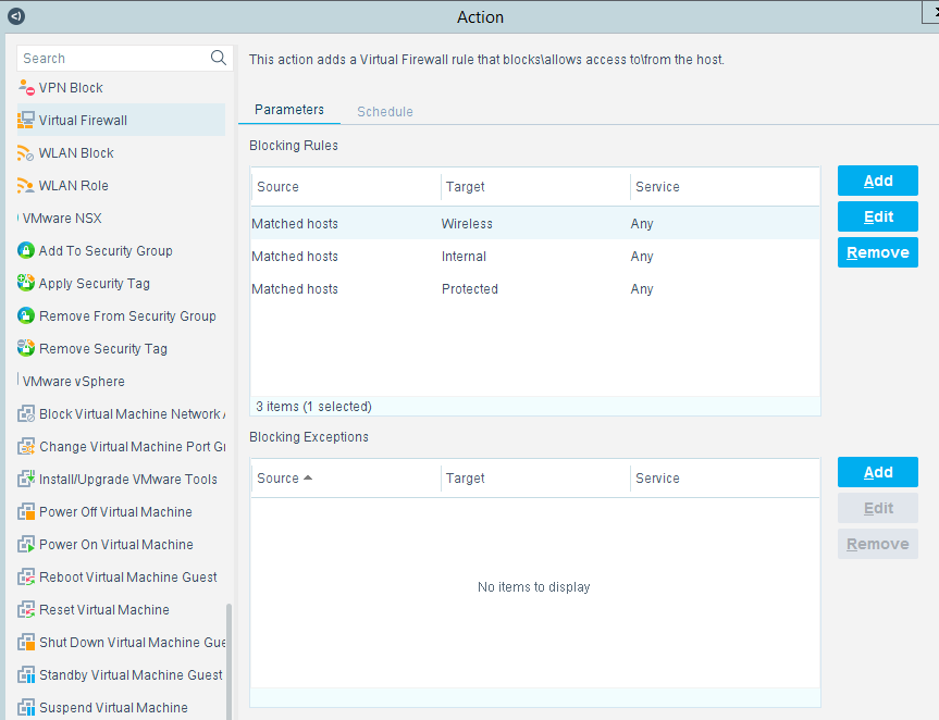
In the Blocking Rules Edit window, select the Inbound/Outbound criteria, the Target IP range, and the Target Port range for the rule:
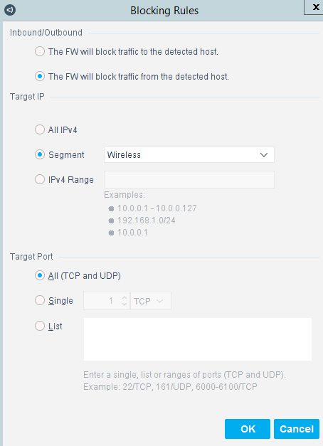
2.8 Virtual Switch—VyOS Configuration
We configured a VyOS router to work with Forescout’s switch plug-in to capture and enforce the policies we deployed for the wireless network. VyOS is a console-based Linux switch/firewall and was used as a virtual switch in our use case.
To begin configuring the switch, we used the following commands. VyOS has good documentation, and we recommend that you reference the documentation if you would like to extend the capabilities of the machine.
$ configure

set interfaces eth2 address dhcp

set interface eth2 description ‘OUTERNET’

set interface eth1 address ‘192.168.0.1/25’

set interface eth1 description ‘WIRELESS’

set service ssh port ‘22’

set nat source rule 100 outbound-interface ‘eth1’

set nat source rule 100 source address ‘192.168.0.0/24’

set nat source rule 100 translation address masquerade

set service dhcp-server shared-network-name LAN subnet 192.168.0.0/24 default-router ‘192.168.0.1’

set service dhcp-server shared-network-name LAN subnet dns-server [FORESCOUT DNS-ENFORCEMENT IP]

set service dhcp-server shared-network-name LAN subnet dns-server ‘192.168.0.1’

set service dhcp-server shared-network-name LAN subnet domain-name ‘hotel-wireless’

set service dhcp-server shared-network-name LAN subnet lease ‘86400’

set service dhcp-server shared-network-name LAN subnet range 0 start 192.168.0.10

set service dhcp-server shared-network-name LAN subnet range 0 stop ‘192.168.0.254’

set service dns forwarding cache-size ‘0‘

set service dns forwarding listen-on ‘eth1’

set service dns forwarding name-server ‘8.8.8.8’

set service dns forwarding name-server ‘1.1.1.1’

set traffic-policy shaper WAN-OUT bandwidth ‘50Mbit’

set traffic-policy shaper WAN-OUT default bandwidth ‘50%’

set traffic-policy shaper WAN-OUT default ceiling ‘100%’

set traffic-policy shaper WAN-OUT default queue-type ‘fair-queue’

set traffic-policy shaper LAN-OUT bandwidth ‘200Mbit’

set traffic-policy shaper LAN-OUT default bandwidth ‘50%’

set traffic-policy shaper LAN-OUT default ceiling ‘100%’

set traffic-policy shaper LAN-OUT default queue-type ‘fair-queue’

set interfaces ethernet eth1 traffic-policy out ‘LAN-OUT’

set interfaces ethernet eth2 traffic-policy out ‘WAN-OUT’

set service snmp community hospitality routers authorization ro

set service snmp community hospitality routers client [FORESCOUT APPLIANCE]

set service snmp trap-target [FORESCOUT APPLIANCE]

set service snmp v3 engineid '0x0aa0d6c6f450'

set service snmp v3 group defaultgroup mode 'ro'

set service snmp v3 group defaultgroup seclevel 'priv'

set service snmp v3 group defaultgroup view 'defaultview'

set service snmp v3 view defaultview oid '1'

set service snmp v3 user hotel_user auth plaintext-key [STRONG PASSWORD]

set service snmp v3 user hotel_user auth type 'md5'

set service snmp v3 user hotel_user engineid '0x0aa0d6c6f450'

set service snmp v3 user hotel_user group 'defaultgroup'

set service snmp v3 user hotel_user mode 'ro'

set service snmp v3 user hotel_user privacy type aes

set service snmp v3 user hotel_user privacy plaintext-key [STRONG PASSWORD]

$ commit

$ save
2.9 Integration of Security Components
In addition to installation and configuration of the individual components, the PMS reference design required a few commands to enable end points with native GUIs to work.
2.9.1 CryptoniteNXT Integration with CLI End Points
Typically, addition of an end point to the CryptoniteNXT protected zone is done through a web browser. In the case of end points without native GUIs, specifically TDi ConsoleWorks and Remediant SecureONE, the following steps must be taken. These instructions rely on CLI access to the end point in question.
$sudo yum install wget

$y

$wget --no-check-certificate --post-data 'username=Administrator&passcode=<TOTP Code>' https://portal.di.ipdr/login