NIST SPECIAL PUBLICATION 1800-26C
Data Integrity:
Detecting and Responding to Ransomware and Other Destructive Events
Volume C:
How-to Guides
Jennifer Cawthra
National Cybersecurity Center of Excellence
NIST
Michael Ekstrom
Lauren Lusty
Julian Sexton
John Sweetnam
The MITRE Corporation
McLean, Virginia
December 2020
FINAL
This publication is available free of charge from https://www.nccoe.nist.gov/projects/building-blocks/data-integrity/detect-respond.

DISCLAIMER
Certain commercial entities, equipment, products, or materials may be identified by name or company logo or other insignia in order to acknowledge their participation in this collaboration or to describe an experimental procedure or concept adequately. Such identification is not intended to imply special status or relationship with NIST or recommendation or endorsement by NIST or NCCoE; neither is it intended to imply that the entities, equipment, products, or materials are necessarily the best available for the purpose.
National Institute of Standards and Technology Special Publication 1800-26C, Natl. Inst. Stand. Technol. Spec. Publ. 1800-26C, 442 pages, (December 2020), CODEN: NSPUE2
FEEDBACK
As a private-public partnership, we are always seeking feedback on our practice guides. We are particularly interested in seeing how businesses apply NCCoE reference designs in the real world. If you have implemented the reference design, or have questions about applying it in your environment, please email us at ds-nccoe@nist.gov.
All comments are subject to release under the Freedom of Information Act.
NATIONAL CYBERSECURITY CENTER OF EXCELLENCE
The National Cybersecurity Center of Excellence (NCCoE), a part of the National Institute of Standards and Technology (NIST), is a collaborative hub where industry organizations, government agencies, and academic institutions work together to address businesses’ most pressing cybersecurity issues. This public-private partnership enables the creation of practical cybersecurity solutions for specific industries, as well as for broad, cross-sector technology challenges. Through consortia under Cooperative Research and Development Agreements (CRADAs), including technology partners—from Fortune 50 market leaders to smaller companies specializing in information technology security—the NCCoE applies standards and best practices to develop modular, adaptable example cybersecurity solutions using commercially available technology. The NCCoE documents these example solutions in the NIST Special Publication 1800 series, which maps capabilities to the NIST Cybersecurity Framework and details the steps needed for another entity to re-create the example solution. The NCCoE was established in 2012 by NIST in partnership with the State of Maryland and Montgomery County, Maryland.
NIST CYBERSECURITY PRACTICE GUIDES
NIST Cybersecurity Practice Guides (Special Publication 1800 series) target specific cybersecurity challenges in the public and private sectors. They are practical, user-friendly guides that facilitate the adoption of standards-based approaches to cybersecurity. They show members of the information security community how to implement example solutions that help them align with relevant standards and best practices, and provide users with the materials lists, configuration files, and other information they need to implement a similar approach.
The documents in this series describe example implementations of cybersecurity practices that businesses and other organizations may voluntarily adopt. These documents do not describe regulations or mandatory practices, nor do they carry statutory authority.
ABSTRACT
Ransomware, destructive malware, insider threats, and even honest mistakes present an ongoing threat to organizations that manage data in various forms. Database records and structure, system files, configurations, user files, application code, and customer data are all potential targets of data corruption and destruction.
A quick, accurate, and thorough detection and response to a loss of data integrity can save an organization time, money, and headaches. While human knowledge and expertise is an essential component of these tasks, the right tools and preparation are essential to minimizing downtime and losses due to data integrity events. The NCCoE, in collaboration with members of the business community and vendors of cybersecurity solutions, has built an example solution to address these data integrity challenges. This project details methods and potential tool sets that can detect, mitigate, and contain data integrity events in the components of an enterprise network. It also identifies tools and strategies to aid in a security team’s response to such an event.
KEYWORDS
attack vector; data integrity; malicious actor; malware; malware detection; malware response; ransomware.
ACKNOWLEDGMENTS
We are grateful to the following individuals for their generous contributions of expertise and time.
Name |
Organization |
|---|---|
Kyle Black |
Bay Dynamics |
Sunjeet Randhawa |
Broadcom Inc. |
Peter Romness |
Cisco Systems |
Matthew Hyatt |
Cisco Systems |
Matthew Shabat |
Glasswall Government Solutions |
Justin Rowland |
Glasswall Government Solutions |
Greg Rhein |
Glasswall Government Solutions |
Steve Roberts |
Micro Focus |
Timothy McBride |
NIST |
Christopher Lowde |
Semperis |
Thomas Leduc |
Semperis |
Darren Mar-Elia |
Semperis |
Kirk Lashbrook |
Semperis |
Mickey Bresman |
Semperis |
Humphrey Christian |
Symantec Corporation |
Jon Christmas |
Symantec Corporation |
Kenneth Durbin |
Symantec Corporation |
Matthew Giblin |
Symantec Corporation |
Jim Wachhaus |
Tripwire |
Nancy Correll |
The MITRE Corporation |
Chelsea Deane |
The MITRE Corporation |
Sallie Edwards |
The MITRE Corporation |
Milissa McGinnis |
The MITRE Corporation |
Karri Meldorf |
The MITRE Corporation |
Denise Schiavone |
The MITRE Corporation |
Anne Townsend |
The MITRE Corporation |
The Technology Partners/Collaborators who participated in this build submitted their capabilities in response to a notice in the Federal Register. Respondents with relevant capabilities or product components were invited to sign a Cooperative Research and Development Agreement (CRADA) with NIST, allowing them to participate in a consortium to build this example solution. We worked with:
Technology Partner/Collaborator |
Build Involvement |
|---|---|
Symantec Corporation |
Symantec Information Centric Analytics v6.5.2 Symantec Security Analytics v8.0.1 |
Cisco Systems |
Cisco Identity Services Engine v2.4, Cisco Advanced Malware Protection v5.4, Cisco Stealthwatch v7.0.0 |
Glasswall Government Solutions |
Glasswall FileTrust ATP for Email v6.90.2.5 |
Tripwire |
Tripwire Log Center v7.3.1, Tripwire Enterprise v8.7 |
Micro Focus |
Micro Focus ArcSight Enterprise Security Manager v7.0 Patch 2 |
Semperis |
Semperis Directory Services Protector v2.7 |
1 Introduction
The following guides show IT professionals and security engineers how we implemented this example solution. We cover all of the products employed in this reference design. We do not recreate the product manufacturers’ documentation, which is presumed to be widely available. Rather, these guides show how we incorporated the products together in our environment.
Note: These are not comprehensive tutorials. There are many possible service and security configurations for these products that are out of scope for this reference design.
1.1 Practice Guide Structure
This NIST Cybersecurity Practice Guide demonstrates a standards-based reference design and provides users with the information they need to replicate the data integrity detection and response solution. This reference design is modular and can be deployed in whole or in parts.
This guide contains three volumes:
NIST SP 1800-26A: Executive Summary
NIST SP 1800-26B: Approach, Architecture, and Security Characteristics – what we built and why
NIST SP 1800-26C: How-To Guides – instructions for building the example solution (you are here)
Depending on your role in your organization, you might use this guide in different ways:
Business decision makers, including chief security and technology officers will be interested in the Executive Summary (NIST SP 1800-26A), which describes the:
challenges enterprises face in detecting and responding to data integrity events
example solution built at the NCCoE
benefits of adopting the example solution
Technology or security program managers who are concerned with how to identify, understand, assess, and mitigate risk will be interested in NIST SP 1800-26B, which describes what we did and why. The following sections will be of particular interest:
Section 3.4.1, Risk, provides a description of the risk analysis we performed.
Section 3.4.2, Security Control Map, maps the security characteristics of this example solution to cybersecurity standards and best practices.
You might share the Executive Summary, NIST SP 1800-26A, with your leadership team members to help them understand the importance of adopting standards-based data integrity solutions.
IT professionals who want to implement an approach like this will find the whole practice guide useful. You can use the How-To portion of the guide, NIST SP 1800-26C, to replicate all or parts of the build created in our lab. The How-To guide provides specific product installation, configuration, and integration instructions for implementing the example solution. We do not recreate the product manufacturers’ documentation, which is generally widely available. Rather, we show how we incorporated the products together in our environment to create an example solution.
This guide assumes that IT professionals have experience implementing security products within the enterprise. While we have used a suite of commercial products to address this challenge, this guide does not endorse these particular products. Your organization can adopt this solution or one that adheres to these guidelines in whole, or you can use this guide as a starting point for tailoring and implementing parts of a data integrity detection and response solution. Your organization’s security experts should identify the products that will best integrate with your existing tools and IT system infrastructure. We hope you will seek products that are congruent with applicable standards and best practices. Volume B, Section 3.5, Technologies, lists the products we used and maps them to the cybersecurity controls provided by this reference solution.
A NIST Cybersecurity Practice Guide does not describe “the” solution, but a possible solution. This is a draft guide. We seek feedback on its contents and welcome your input. Comments, suggestions, and success stories will improve subsequent versions of this guide. Please contribute your thoughts to ds-nccoe@nist.gov.
1.2 Build Overview
The NCCoE built a hybrid virtual-physical laboratory environment to explore methods to effectively detect and respond to a data corruption event in various Information Technology (IT) enterprise environments. NCCoE also explored the issues of analysis and reporting to support incident response. The servers in the virtual environment were built to the hardware specifications of their specific software components.
The NCCoE worked with members of the Data Integrity Community of Interest to develop a diverse (but non-comprehensive) set of use case scenarios against which to test the reference implementation. These are detailed in Volume B, Section 5.2. For a detailed description of our architecture, see Volume B, Section 4.
1.3 Typographical Conventions
The following table presents typographic conventions used in this volume.
Typeface/ Symbol |
Meaning |
Example |
|---|---|---|
Italics |
filenames and pathnames references to documents that are not hyperlinks, new terms, and placeholders |
For detailed definitions of terms, see the NCCoE Glossary. |
Bold |
names of menus, options, command buttons and fields |
Choose File > Edit. |
Monospace |
command-line input, on-screen computer output, sample code examples, status codes |
|
blue text |
link to other parts of the document, a web URL, or an email address |
All publications from NIST’s National Cybersecurity Center of Excellence are available at http://nccoe.nist.gov. |
2 Product Installation Guides
This section of the practice guide contains detailed instructions for installing and configuring all of the products used to build an instance of the example solution.
2.1 Active Directory and Domain Name System Server
As part of our enterprise emulation, we included an Active Directory server that doubles as a Domain Name System (DNS) server. This section covers the installation and configuration process used to set up Active Directory and DNS on a Windows Server 2012 R2 machine.
2.1.1 Install Features
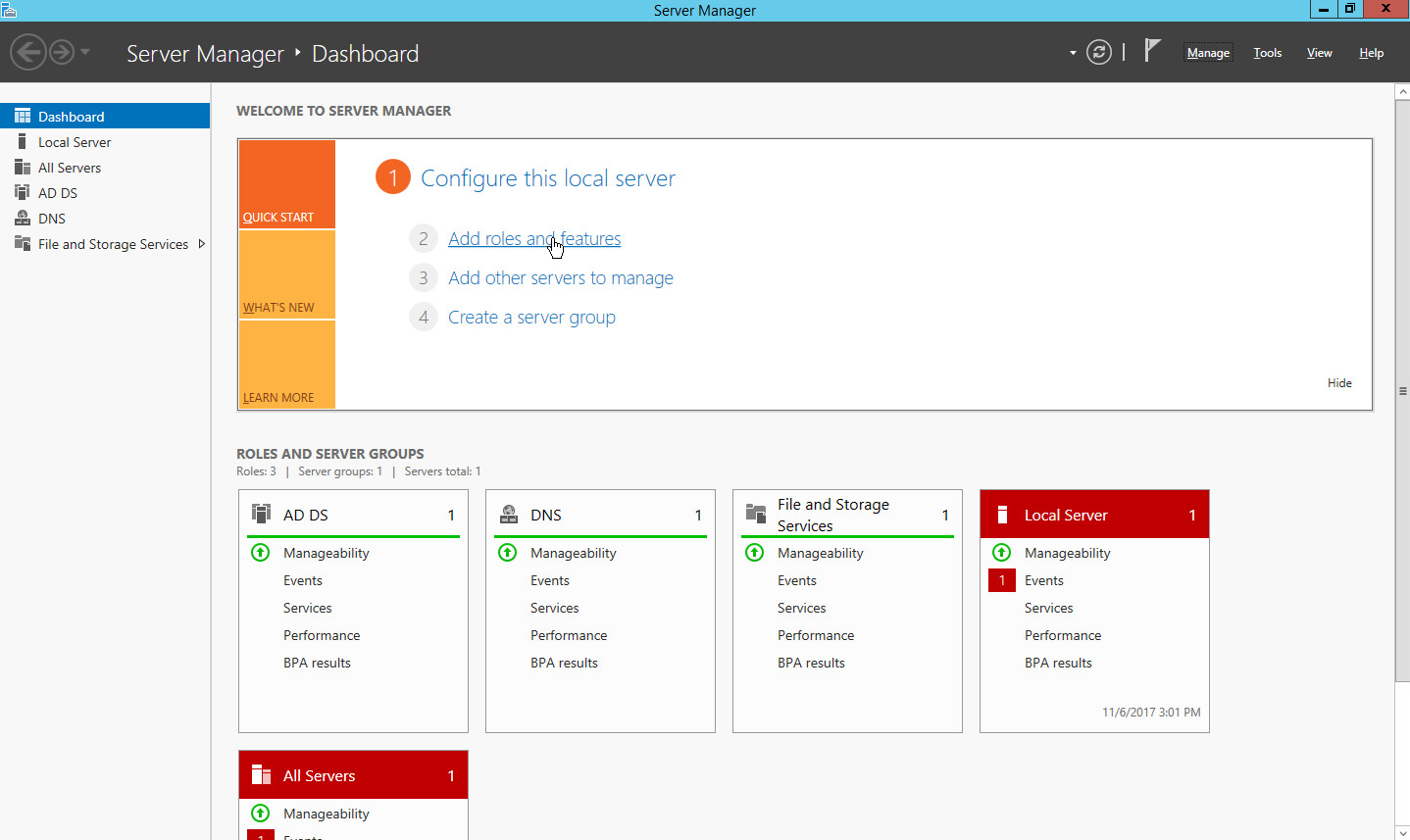
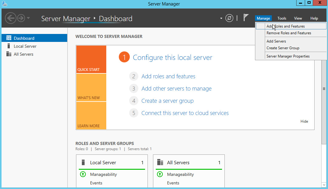
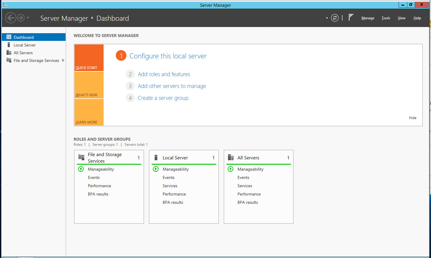
Open Server Manager.
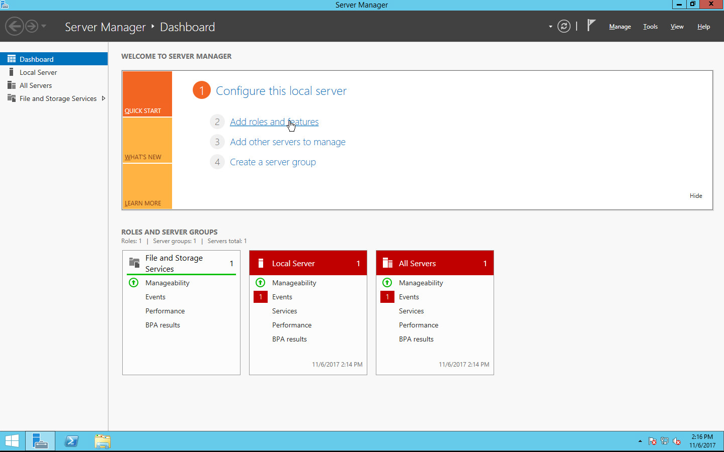
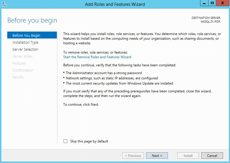
Click the link Add roles and features.
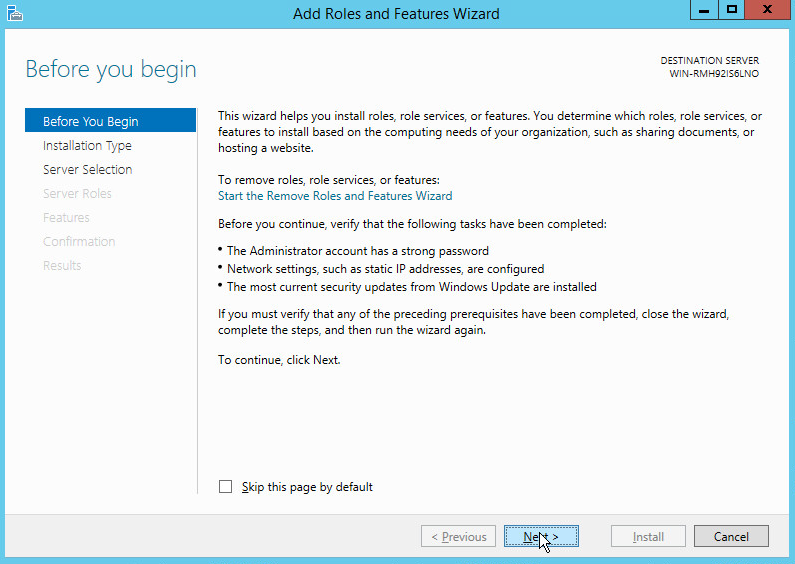
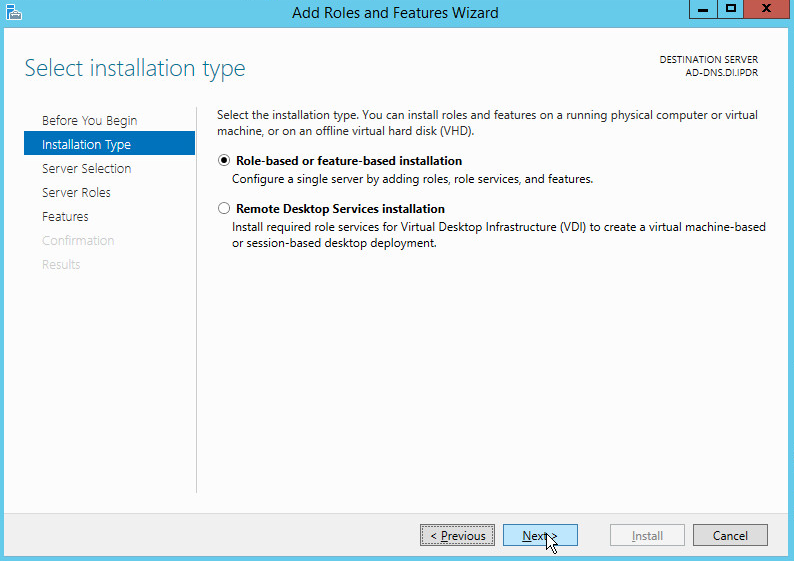
Click Next.
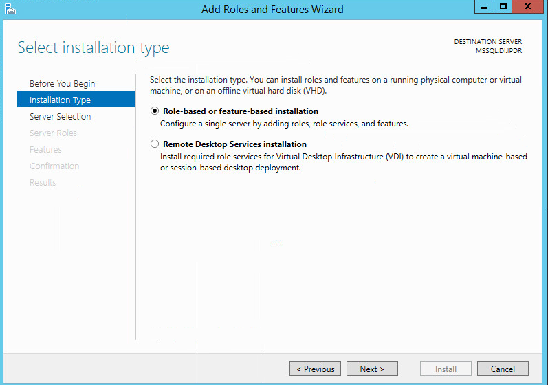
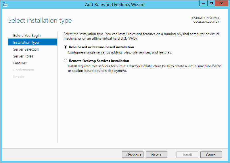
Select Role-based or feature-based installation.

Click Next.
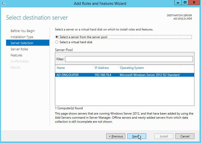
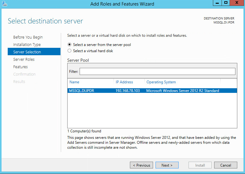
Select Select a server from the server pool.
Select the intended active directory server.
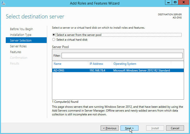
Click Next.
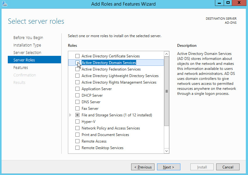
Check the box next to Active Directory Domain Services.
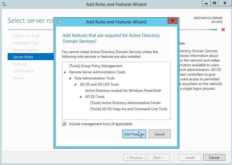
Click Add Features.
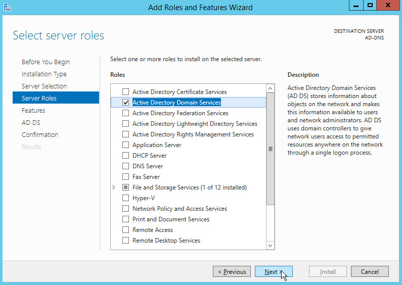
Click Next.
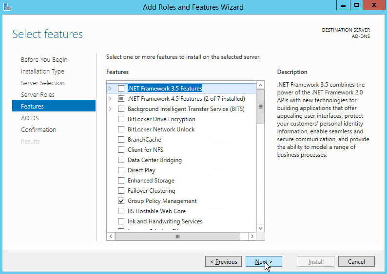
Click Next.
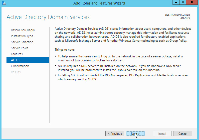
Click Next.
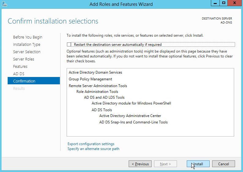
Click Install.
Wait for the installation to complete.
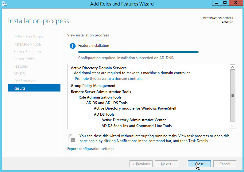
Click Close.
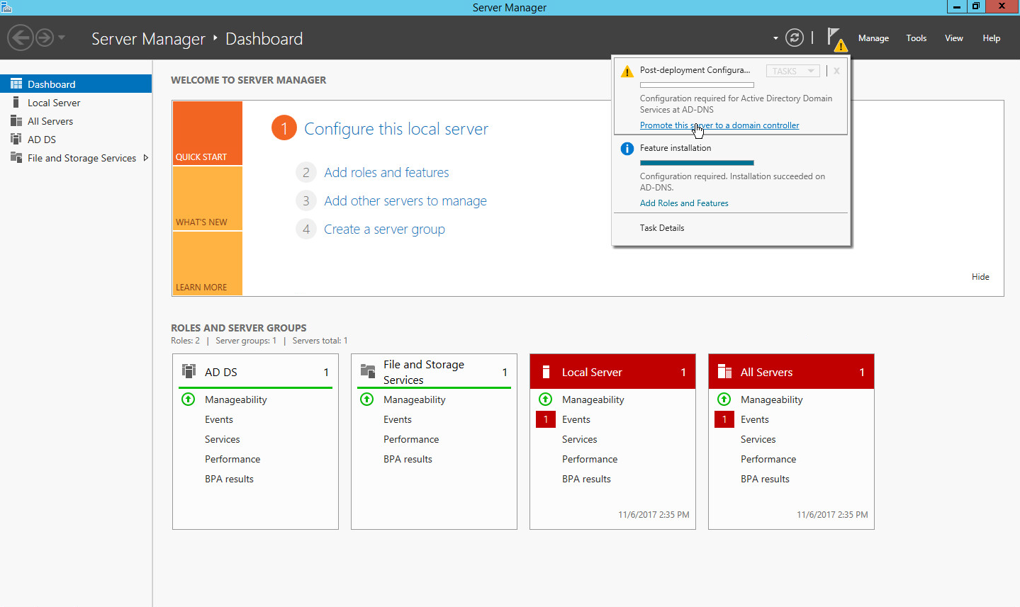
Click Promote this server to a domain controller.
Select Add a new forest.
Enter a Root domain name.
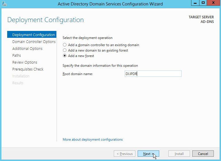
Click Next.
Select Windows Server 2012 R2 for Forest functional level and Domain functional level.
Check the box next to Domain Name System (DNS) server.
Enter a password.
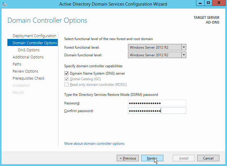
Click Next.
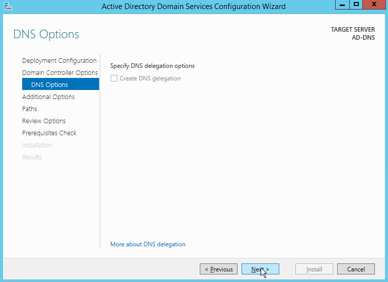
Click Next.
Verify the domain name.
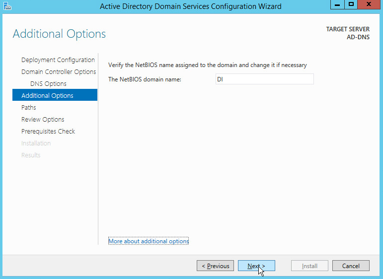
Click Next.
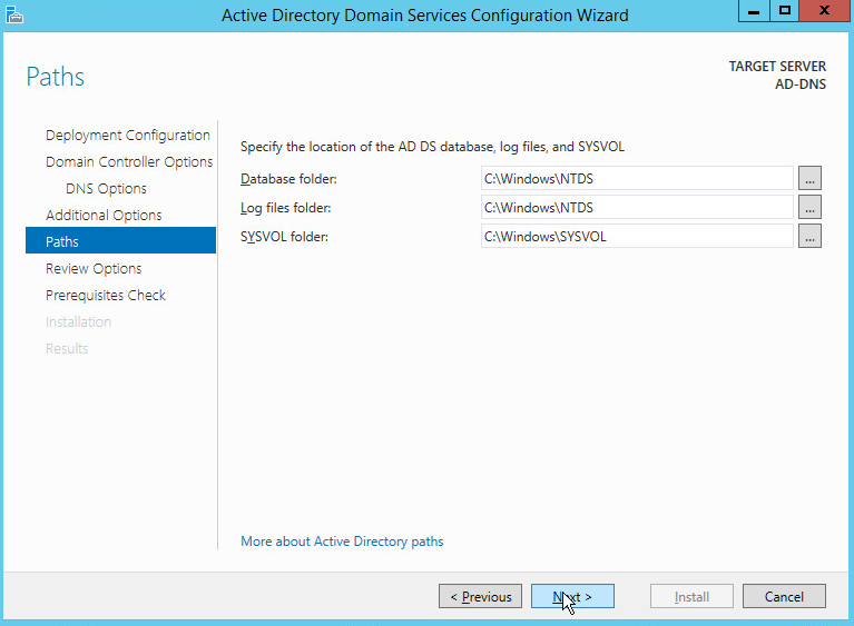
Click Next.
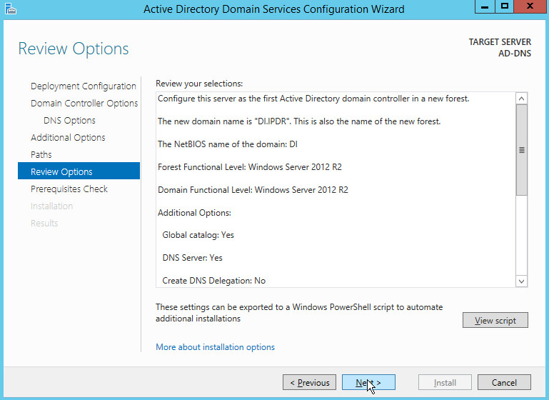
Click Next.
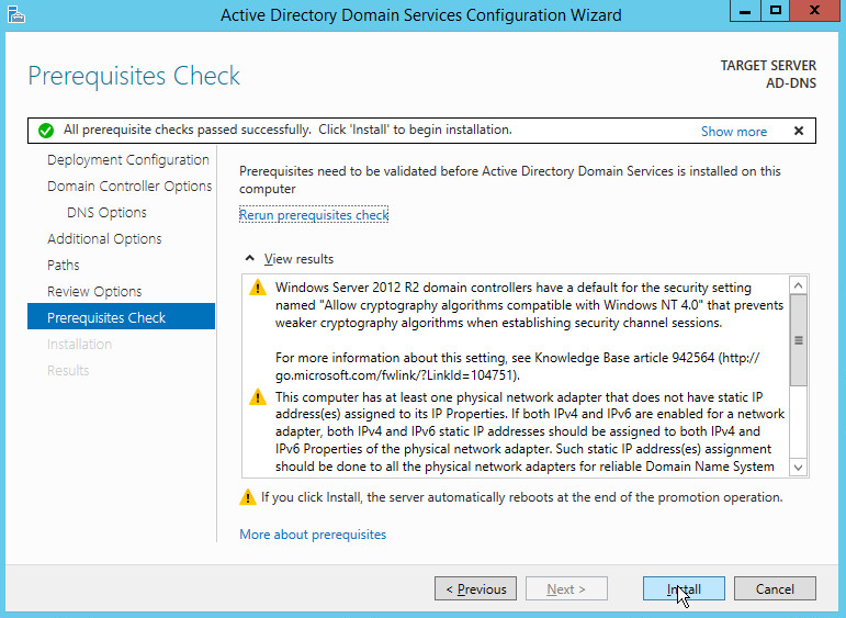
Click Install.
Wait for the installation to complete.
The server automatically reboots.
2.1.2 Create a Certificate Authority
Open Server Manager.
Click Add roles and features.

Click Next.
Select Role-based or feature-based installation.
Click Next.
Select Select a server from the server pool.
Select the intended Active Directory server.
Click Next.
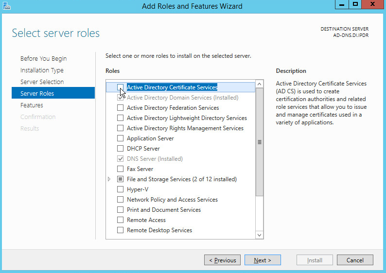
Check the box next to Active Directory Certificate Services.
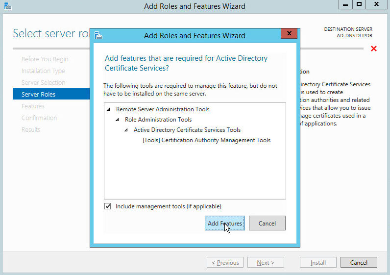
Click Add Features.
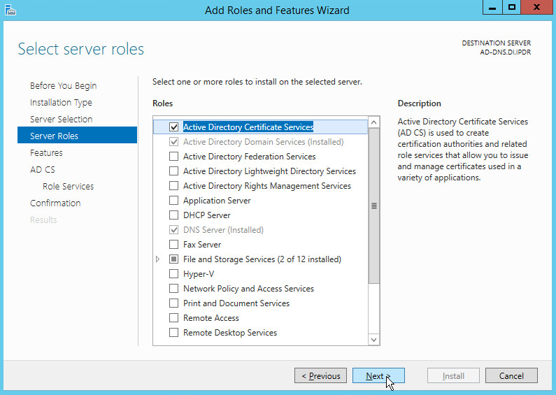
Click Next.
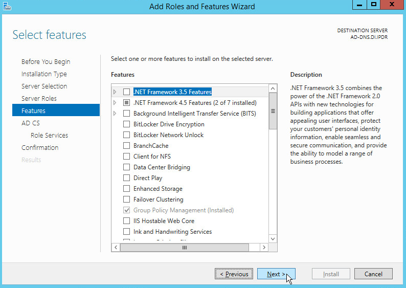
Click Next.
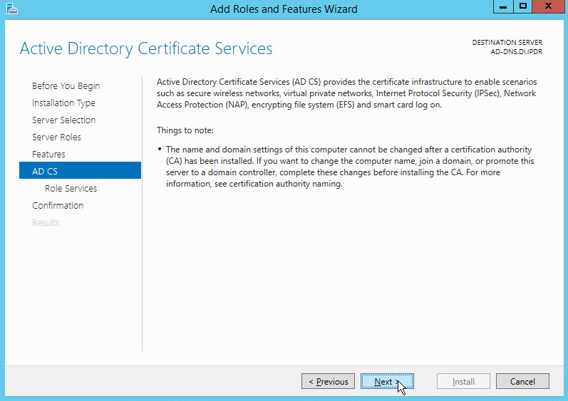
Click Next.
Check the box next to Certification Authority.
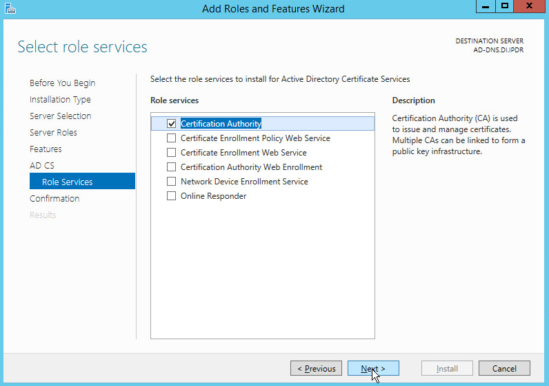
Click Next.
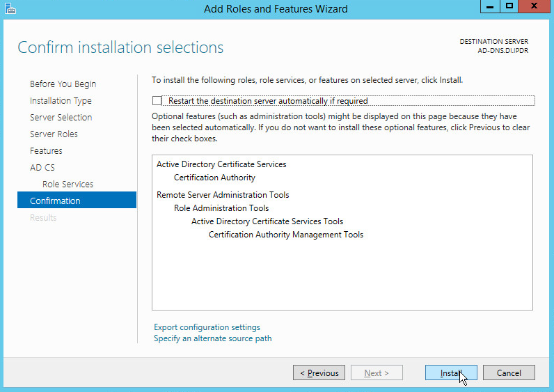
Click Install.
Wait for the installation to complete.
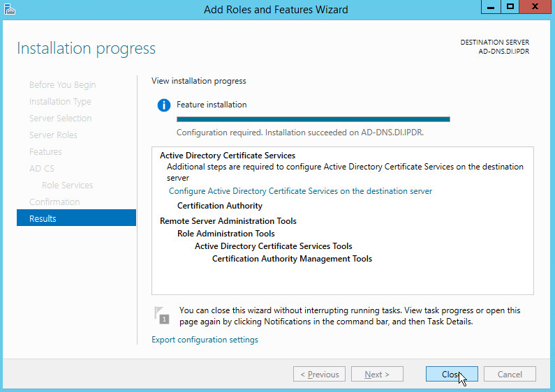
Click Close.
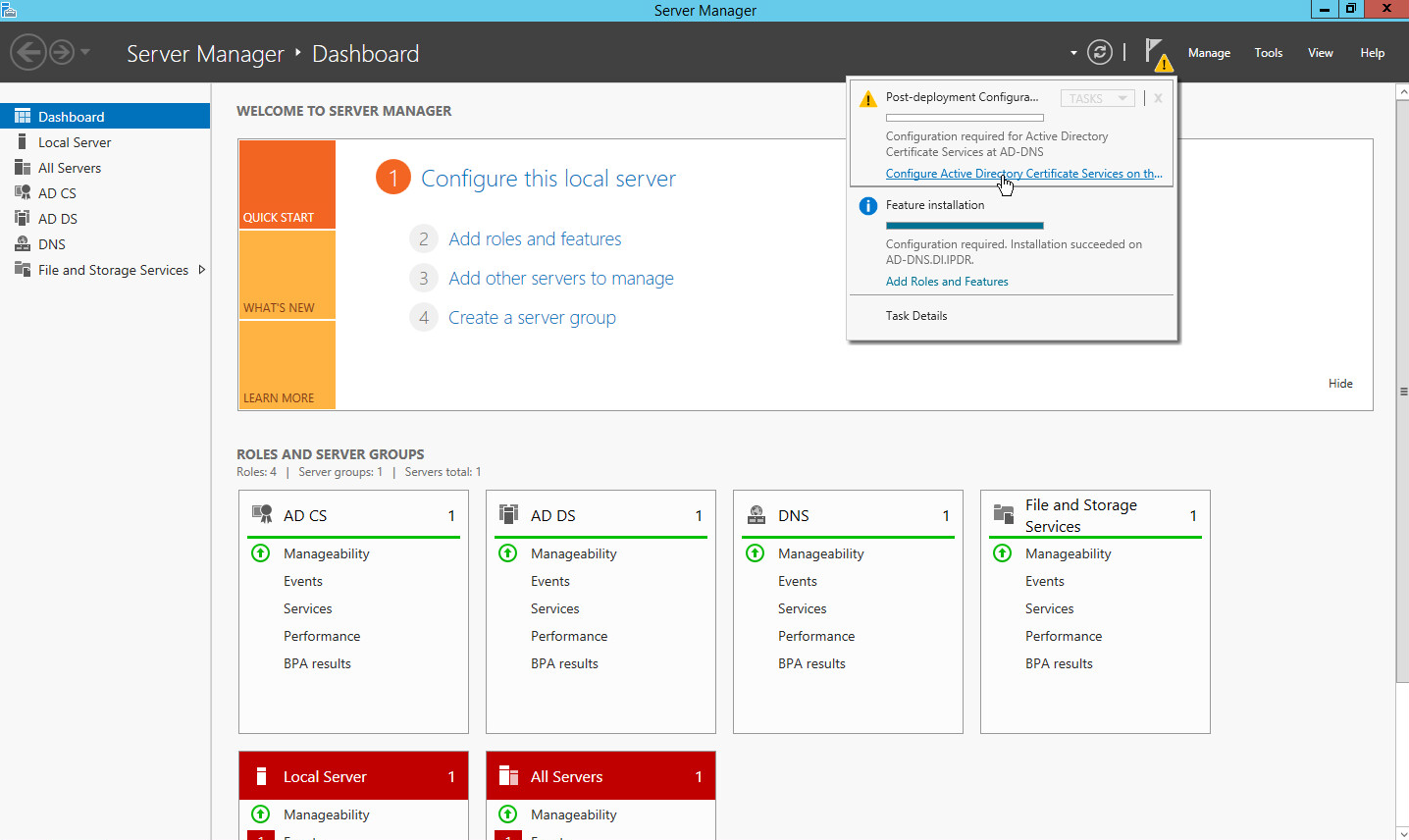
Click Configure Active Directory Certificate Services on the destination server.
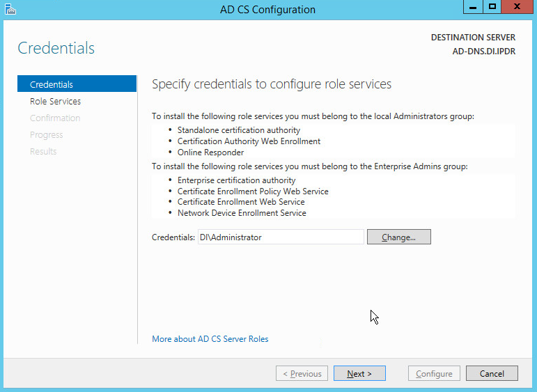
Click Next.
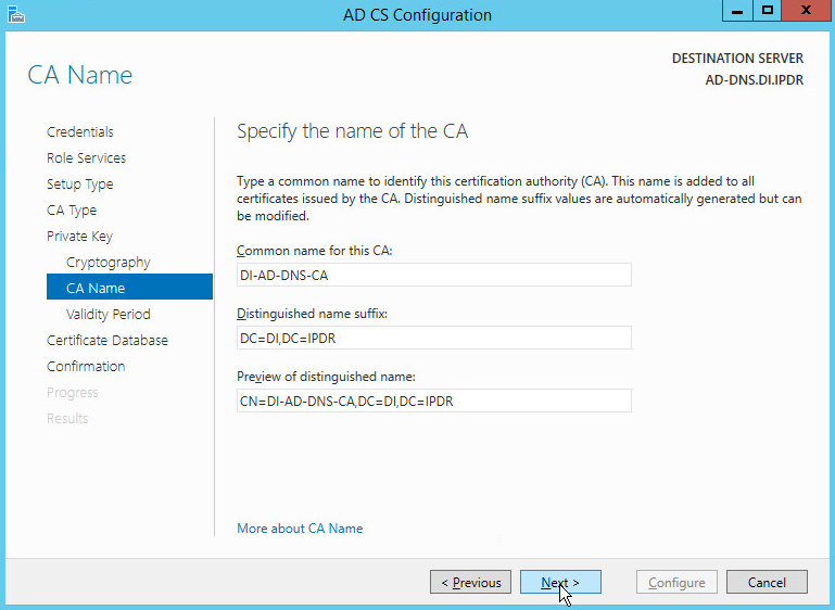
Check the box next to Certification Authority.
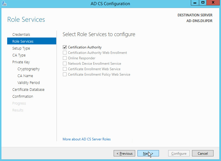
Click Next.
Select Enterprise CA.
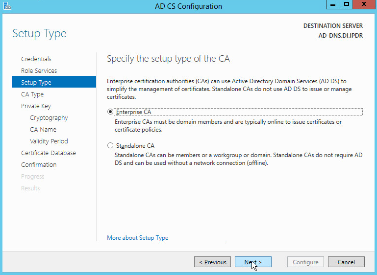
Click Next.
Select Root CA.
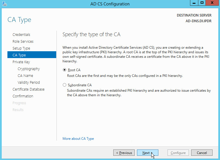
Click Next.
Select Create a new private key.
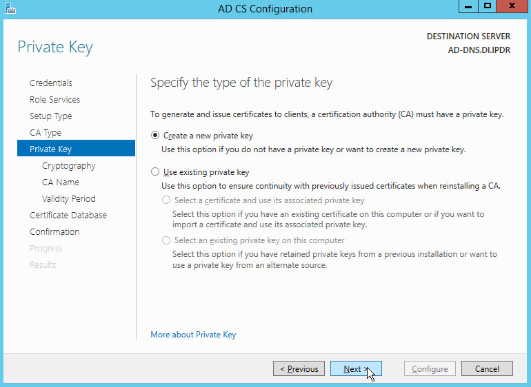
Click Next.
Select RSA#Microsoft Software Key Storage Provider.
Set the Key length to 2048.
Select SHA512 from the list.
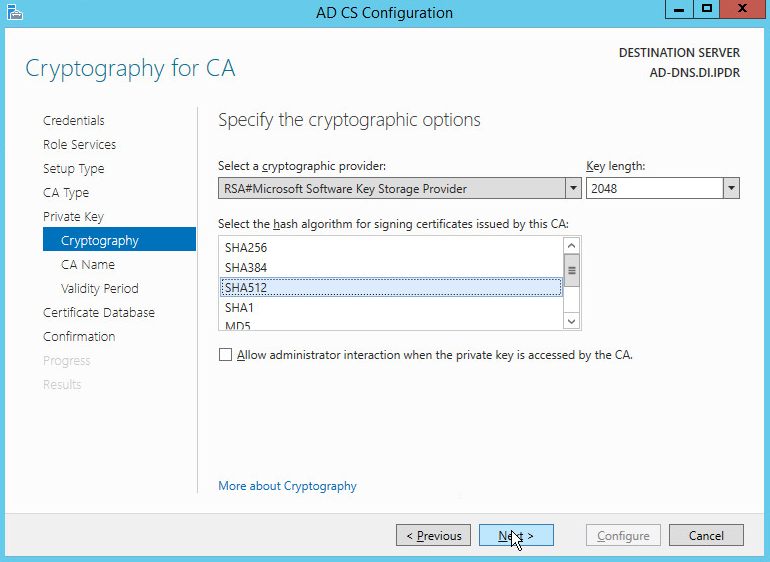
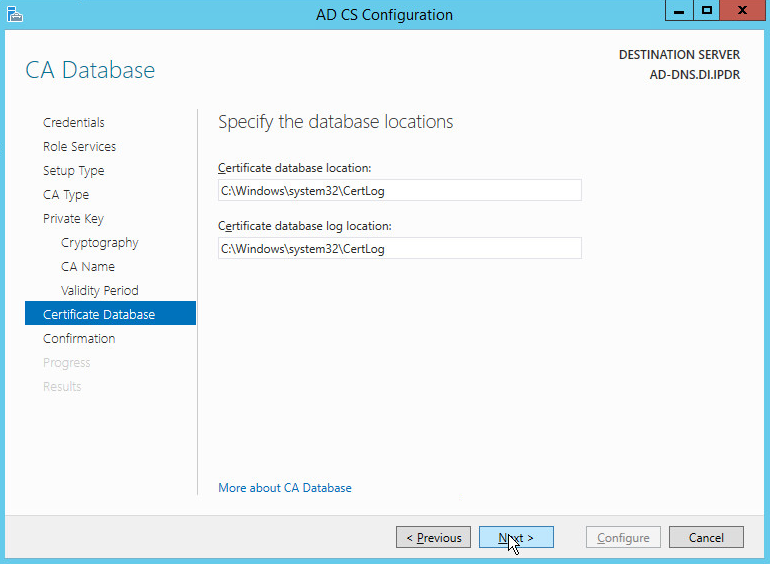
Click Next.
Click Next.
Set the validity period of the certificate according to the needs of your organization.
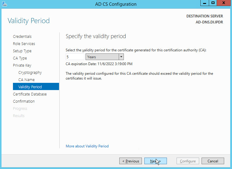
Click Next.
Click Next.
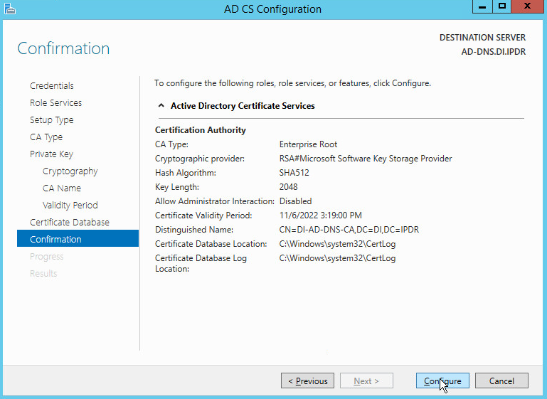
Click Configure.
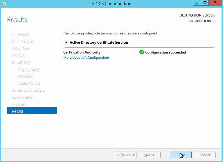
Click Close.
2.1.3 Configure Account to Add Computers to Domain
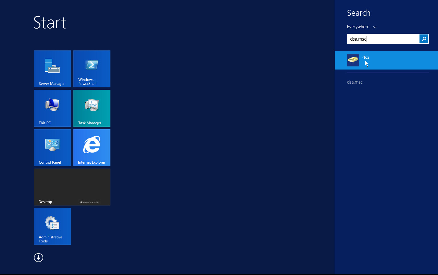
Open the Start menu.
Enter dsa.msc, and run the program.
Right-click on Users in the left panel.
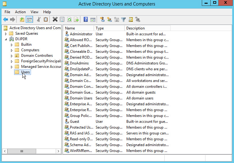
Click Delegate Control.
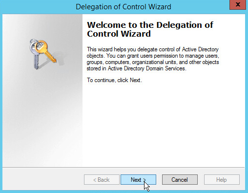
Click Next.
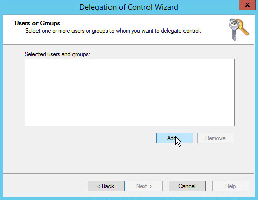
Click Add to select users or groups.
Add users or groups.
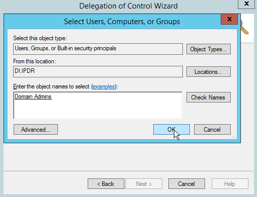
Click OK.
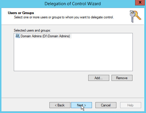
Click Next.
Choose Create a custom task to delegate.
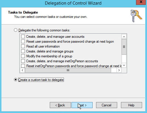
Click Next.
Choose Only the following objects in the folder.
Check the box next to Computer objects.
Check the box next to Create selected objects in this folder.
Check the box next to Delete selected objects in this folder.
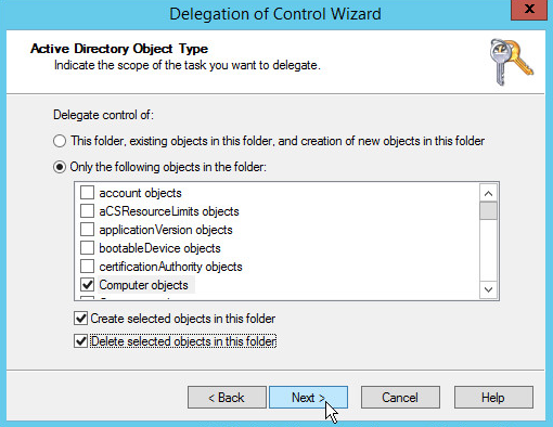
Click Next.
Check the boxes next to Reset password, Read and write account restrictions, Validated write to DNS host name, and Validated write to service principal name.
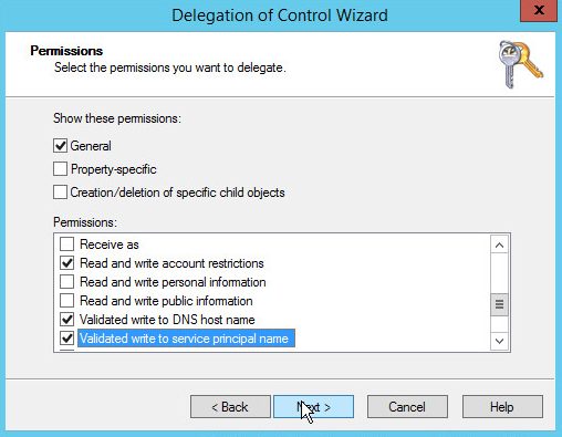
Click Next.
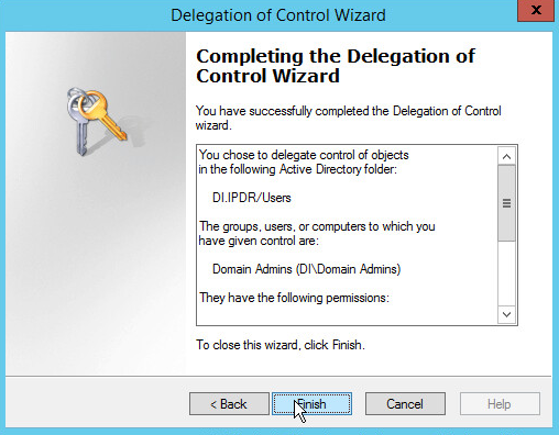
Click Finish.
2.1.4 Add Machines to the Domain
Right-click the network icon in the task bar, on a computer that you wish to add to the domain.
Click Open Network and Sharing Center.
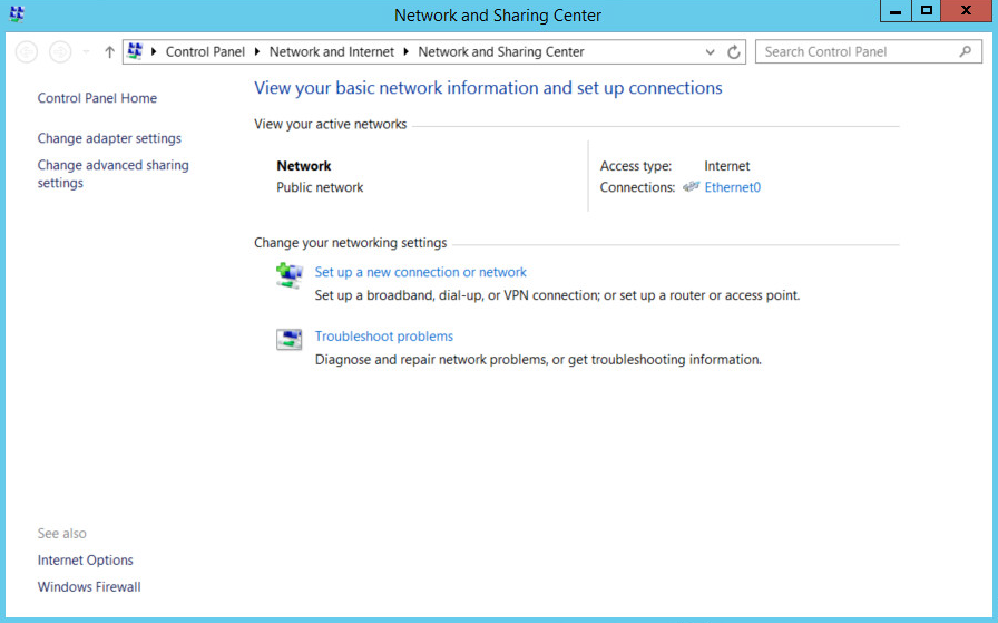
Click the name of the internet adapter.
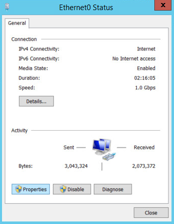
Click Properties.
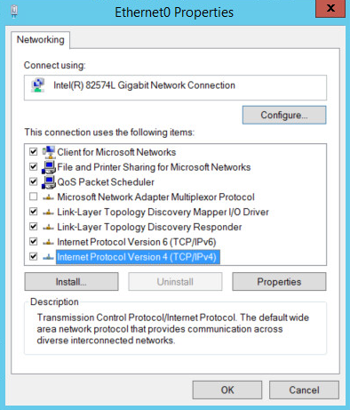
Double-click Internet Protocol Version 4 (TCP/IPv4).
Select Use the following DNS server addresses.
Enter the IP address of the DNS server.
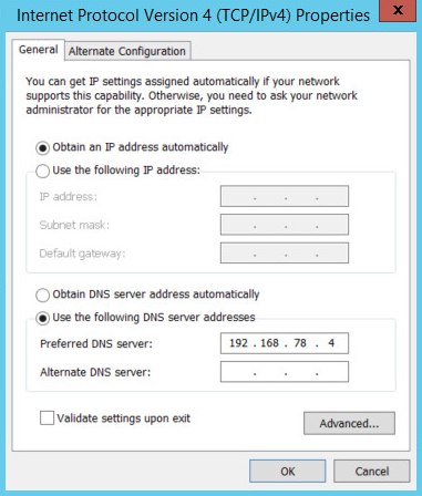
Click OK.
Click OK.
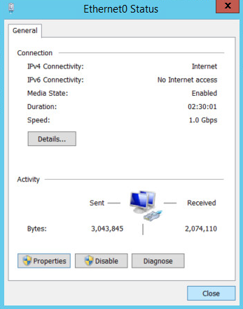
Click Close.
Navigate to This PC.
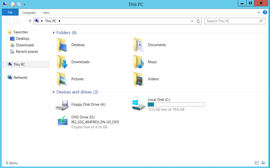
Right-click in the window, and click Properties.
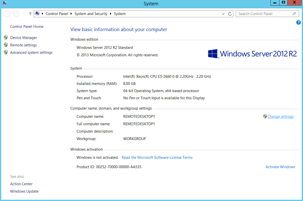
Click Change Settings.
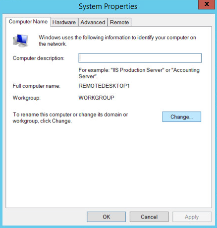
Click Change.
Select Domain.
Enter the domain.
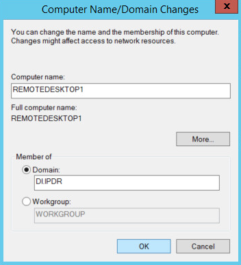
Click OK.
Enter the name and password of an account with privileges to add computers to the domain.
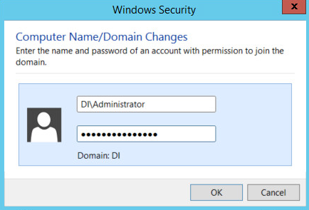
Click OK.
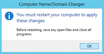
Click OK when prompted to restart the computer.
2.1.5 Configure Active Directory to Audit Account Activity
Open the Start Menu.
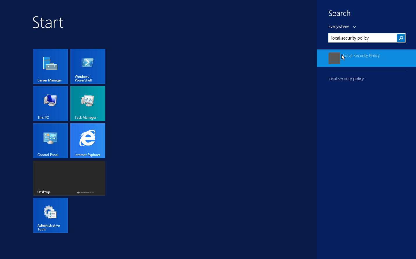
Enter Local Security Policy in the search bar, and open the program.
Navigate to Local Policies > Audit Policy.
Right-click Audit account management.
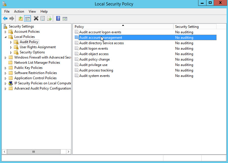
Click Properties.
Check the boxes next to Success and Failure.
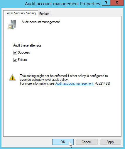
Click OK.
2.1.6 Configure Reverse Lookup Zones
Open DNS Manager by right-clicking the DNS server in Server Manager.
Click Reverse Lookup Zones.
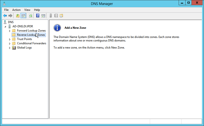
Click Action > New Zone.
Click Next.
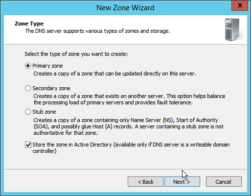
Click Next.
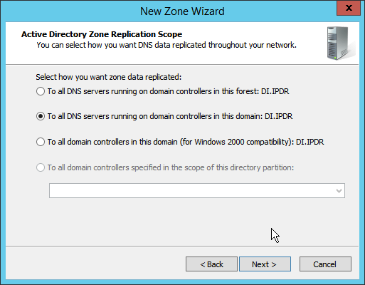
Click Next.
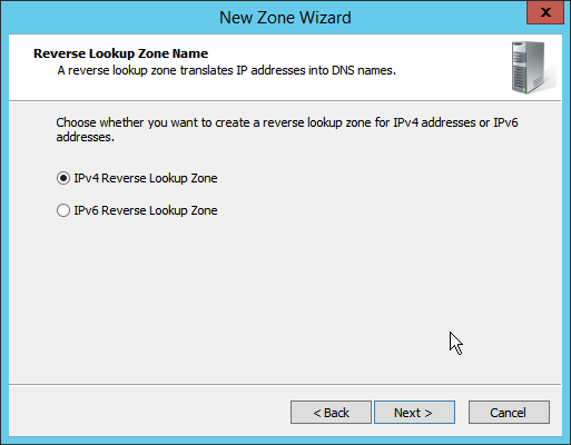
Click Next.
Enter the first three parts of the IP address of the AD/DNS server (for example, 192.168.1).
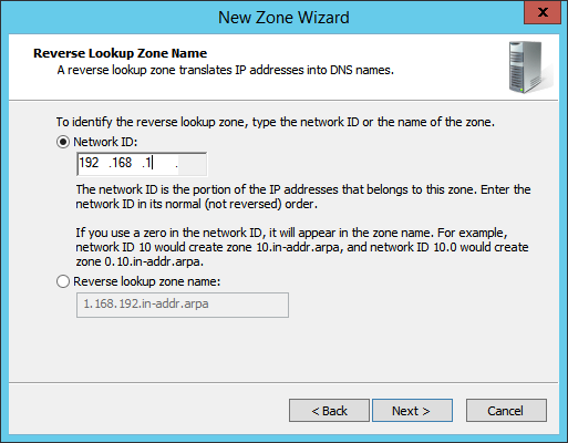
Click Next.
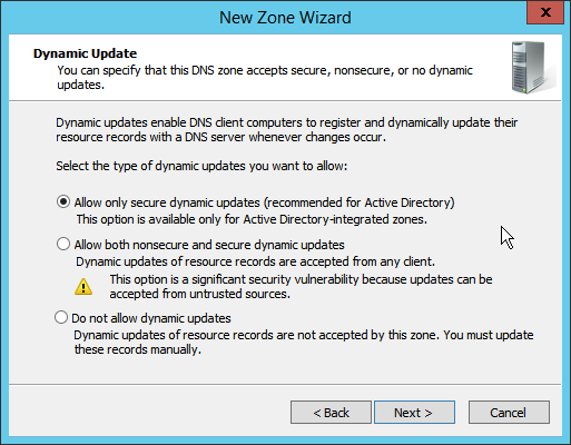
Click Next.
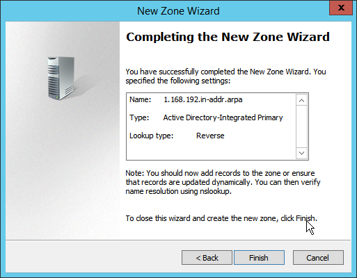
Click Finish.
Click on the newly created reverse lookup zone.
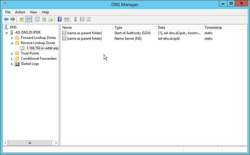
Right-click in the window and select New Pointer (PTR)….
Enter the IP address of the AD/DNS server.
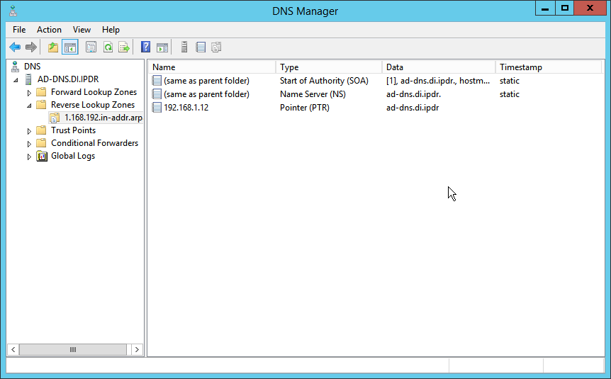
Enter the hostname of the AD/DNS server.
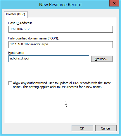
Click OK.
2.2 Microsoft Exchange Server
As part of our enterprise emulation, we include a Microsoft Exchange server. This section covers the installation and configuration process used to set up Microsoft Exchange on a Windows Server 2012 R2 machine.
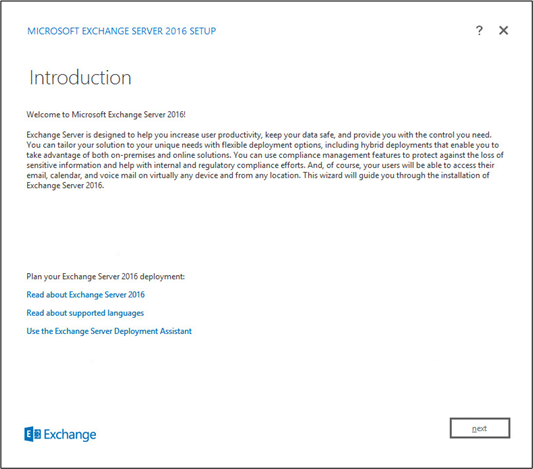
2.2.1 Install Microsoft Exchange
Run Exchange2016-x64.exe.
Choose the directory for the extracted files.
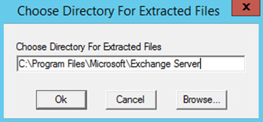
Click OK.
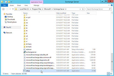
Enter the directory and run setup.exe.
Select Connect to the Internet and check for updates.
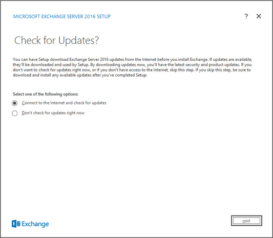
Click Next.
Wait for the check to finish.
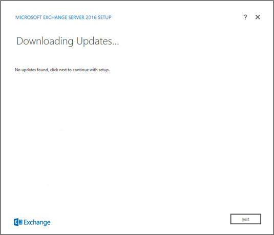
Click Next.
Wait for the copying to finish.
Click Next.
Click I accept the terms in the license agreement.
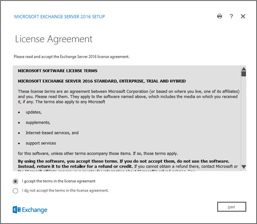
Click Next.
Click Use Recommended Settings.
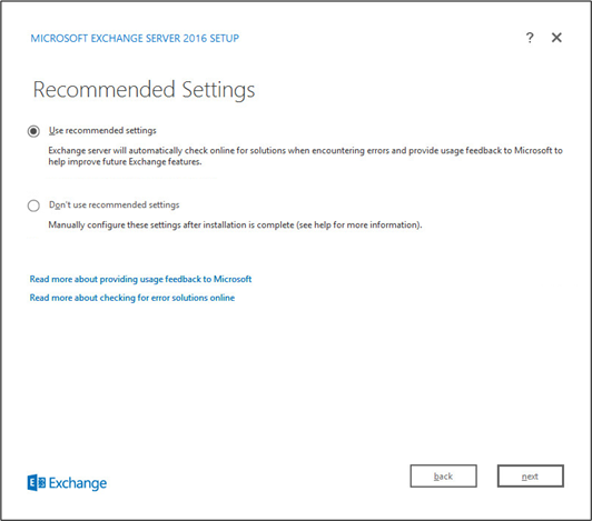
Click Next.
Check Mailbox role.
Check Automatically install Windows Server roles and features that are required to install Exchange Server.
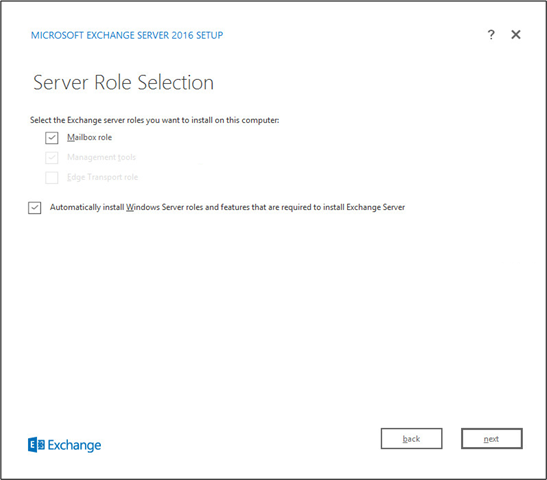
Click Next.
Specify the installation path for MS Exchange.
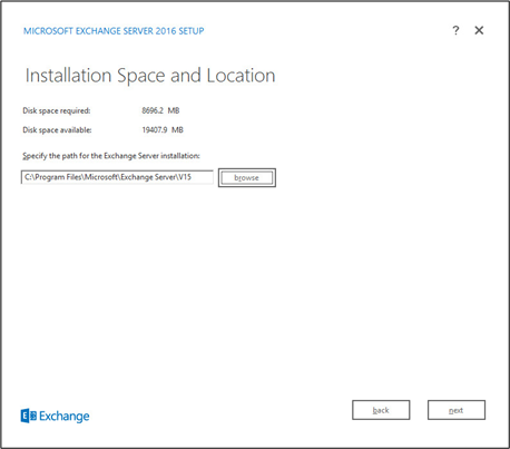
Click Next.
Specify the name for the Exchange organization, for example, DI.
Decide whether to apply split permissions, based on the needs of the enterprise.
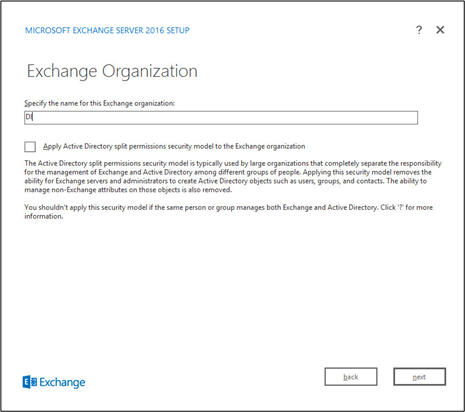
Click Next.
Select No.
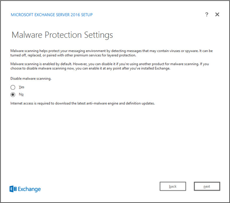
Click Next.
Install any prerequisites listed.
If necessary, restart the server and re-run setup.exe, completing steps 3-22 again.
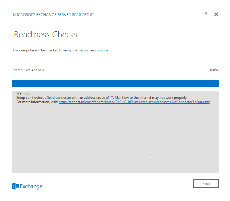
Click Install.
2.3 Windows Server Hyper-V Role
As part of our simulated enterprise, we include a Windows Hyper-V server. This section covers the instructions for installing Windows Server Hyper-V on a Windows Server 2012 R2 machine.
The instructions for enabling the Windows Server Hyper-V Role are retrieved from https://technet.microsoft.com/en-us/library/hh846766(v=ws.11).aspx and are replicated below for preservation and ease of use.
2.3.1 Production Installation
In Server Manager, on the Manage menu, click Add Roles and Features.
On the Before you begin page, verify that your destination server and network environment are prepared for the role and feature you want to install.
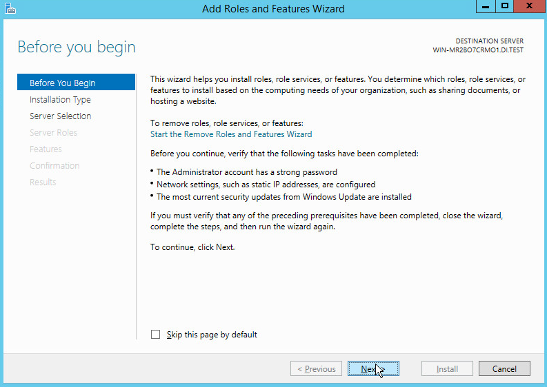
Click Next.
On the Select installation type page, select Role-based or feature-based installation.
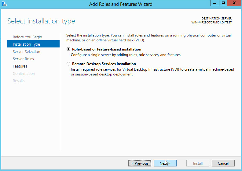
Click Next.
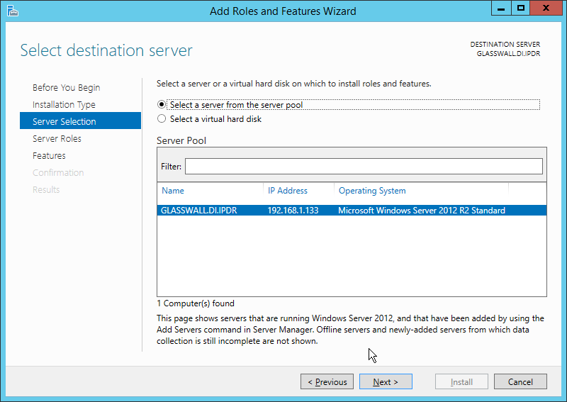
On the Select destination server page, select a server from the server pool.
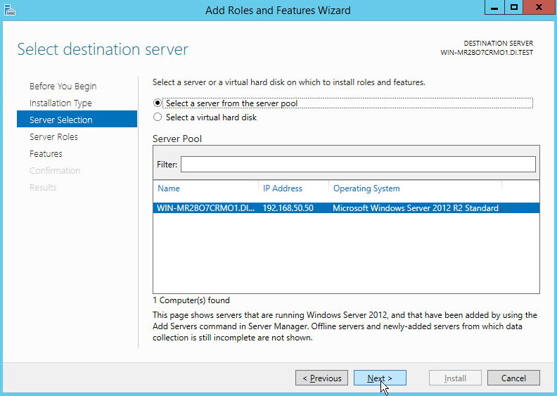
Click Next.
On the Select server roles page, select Hyper-V.
To add the tools that you use to create and manage virtual machines, click Add Features.
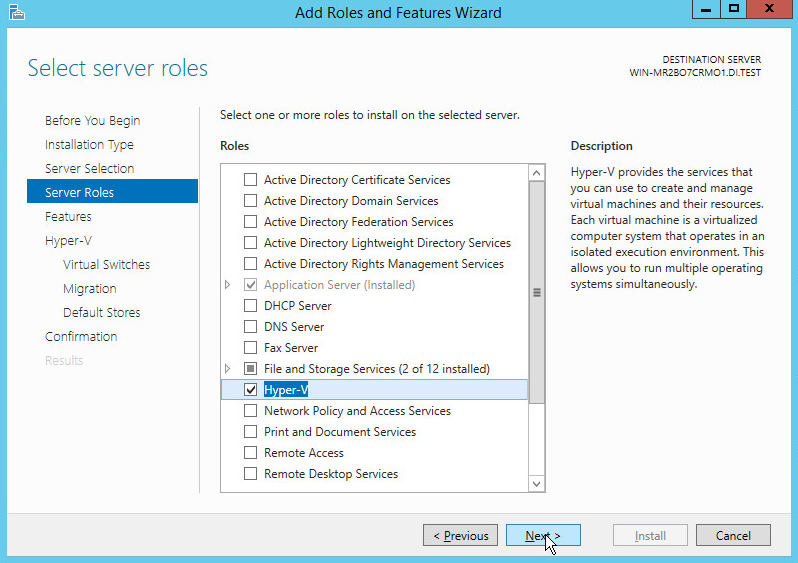
Click Next.
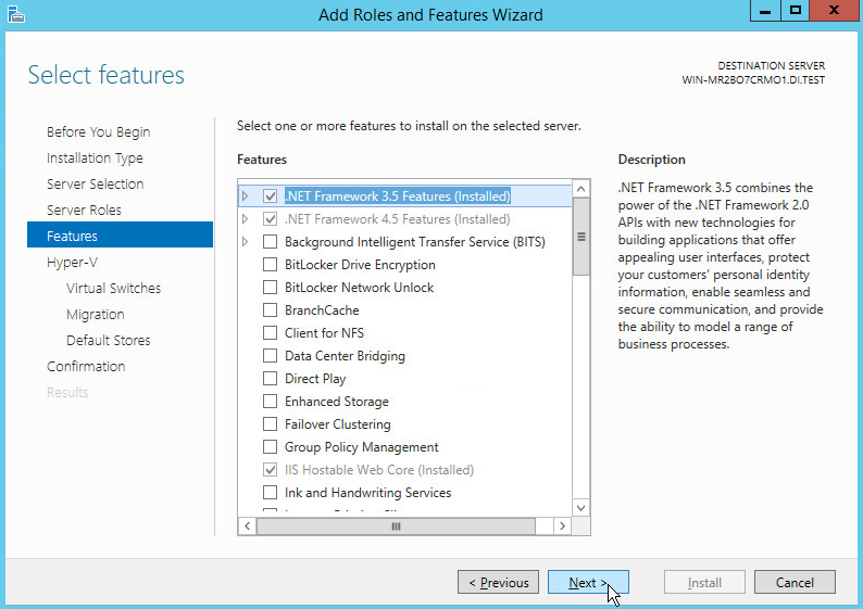
Click Next.
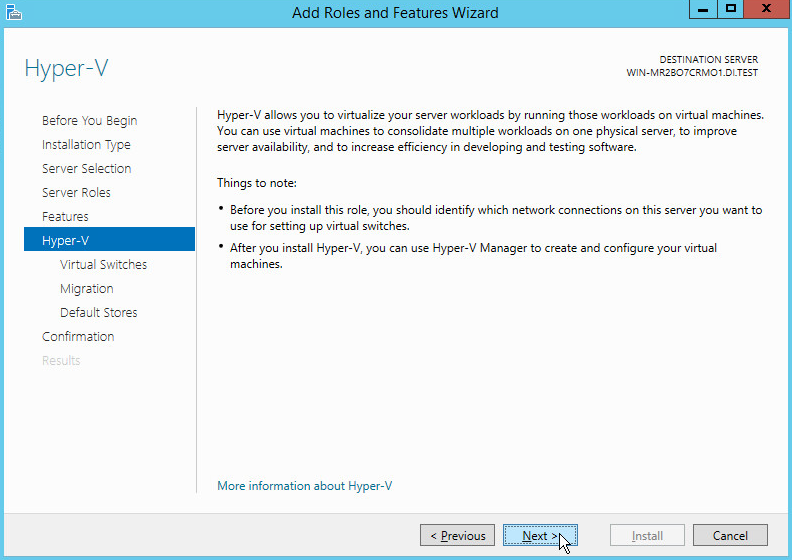
Click Next.
On the Create Virtual Switches page, select the appropriate options.
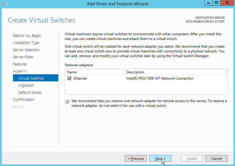
Click Next.
On the Virtual Machine Migration page, select the appropriate options.
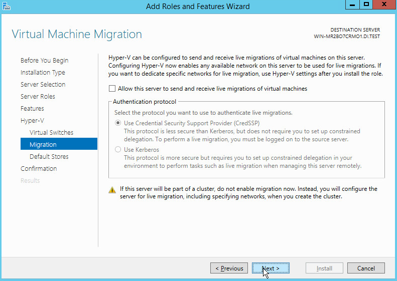
Click Next.
On the Default Stores page, select the appropriate options.
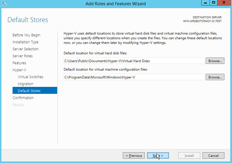
Click Next.
On the Confirm installation selections page, select Restart the destination server automatically if required.
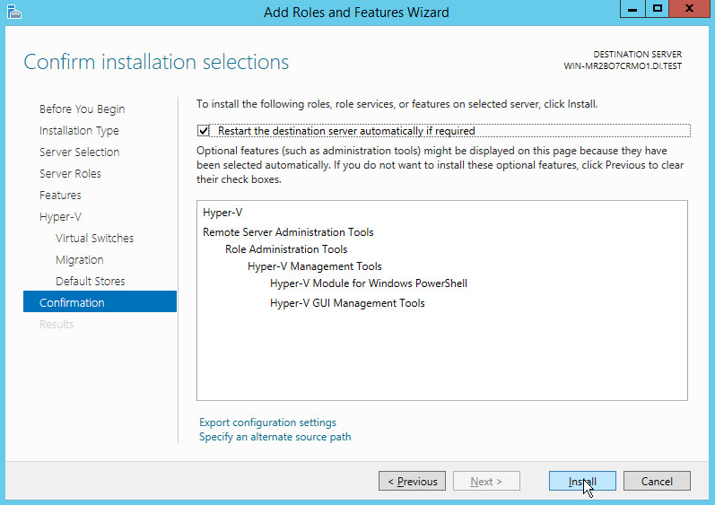
Click Install.
When installation is finished, verify that Hyper-V installed correctly. Open the All Servers page in Server Manager, and select a server on which you installed Hyper-V. Check the Roles and Features tile on the page for the selected server.
2.4 MS SQL Server
As part of both our enterprise emulation and data integrity solution, we include a Microsoft Structured Query Language (SQL) Server. This section covers the installation and configuration process used to set up Microsoft SQL Server on a Windows Server 2012 R2 machine.
2.4.1 Install and Configure MS SQL
Acquire SQL Server 2014 Installation Media.
Locate the installation media in the machine and click on SQL2014_x64_ENU to launch SQL Server Installation Center.
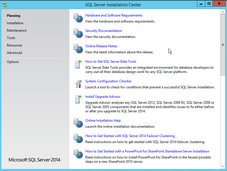
On the left menu, select Installation.
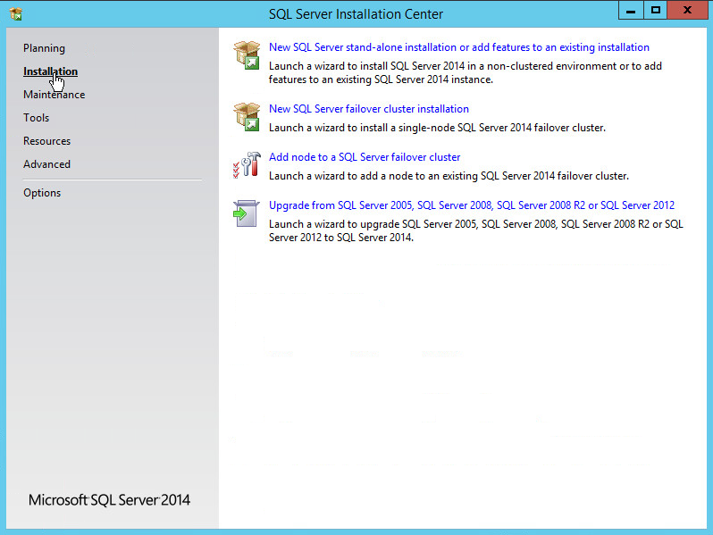
Select New SQL Server stand-alone installation or add features to an existing installation. This will launch the SQL Server 2014 setup.
In the Product Key section, enter your product key.
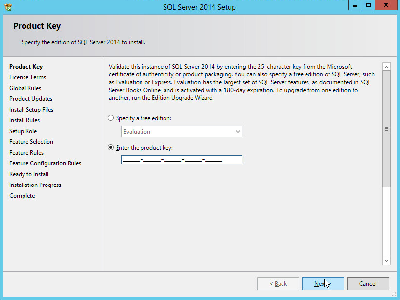
Click Next.
In the License Terms section, read and click I accept the license terms.
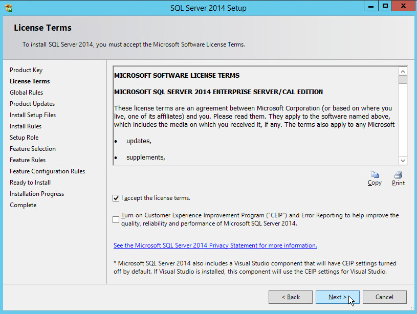
Click Next.
In the Install Rules section, note and resolve any further conflicts.
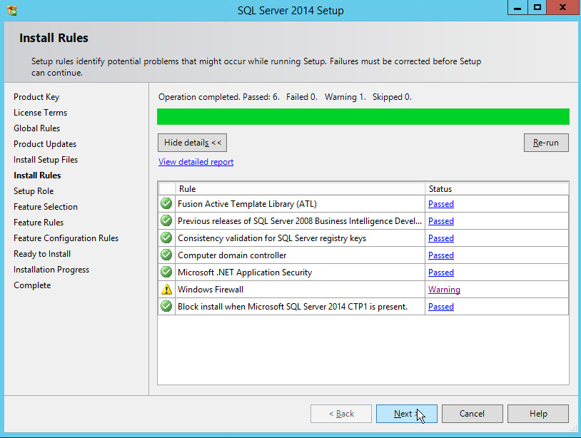
Click Next.
In the Setup Role section, select SQL Server Feature Installation.
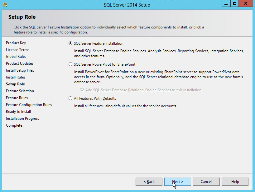
Click Next.
In the Feature Selection section, select the following:
Database Engine Services
Client Tools Connectivity
Client Tools Backwards Compatibility
Client Tools SDK
Management Tools – Basic
Management Tools – Complete
SQL Client Connectivity SDK
Any other desired features
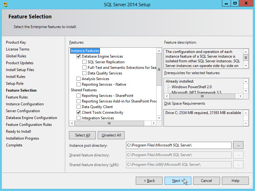
Click Next.
In the Instance Configuration section, select Default instance.
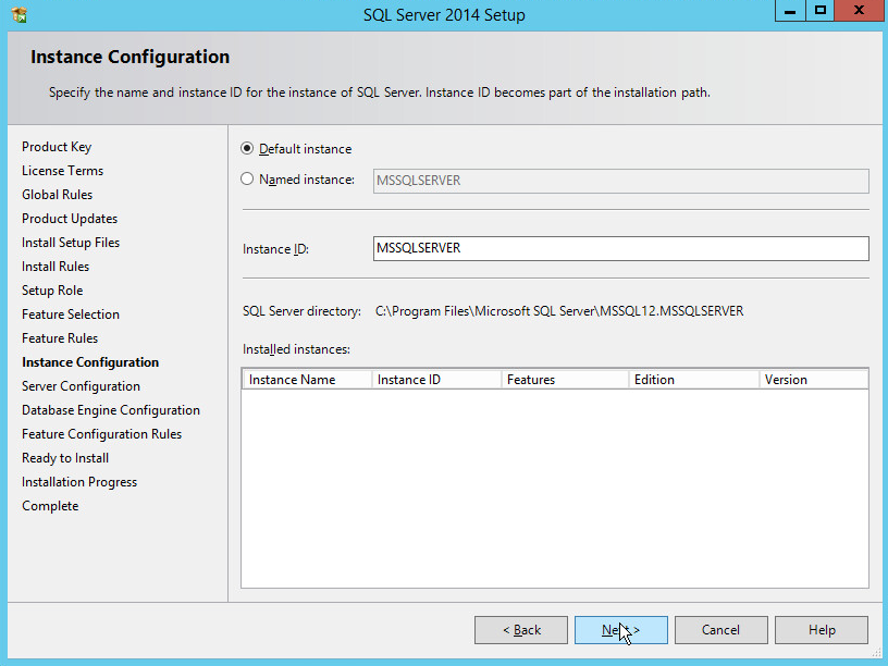
Click Next.
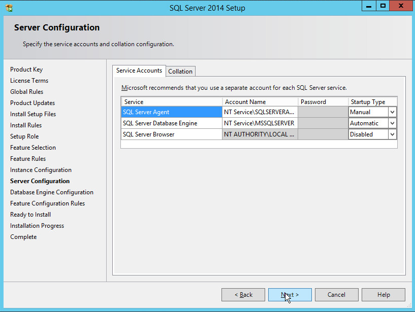
In the Server Configuration section, click Next.
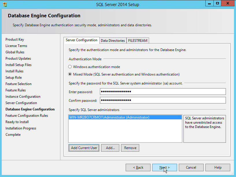
In the Database Engine Configuration section, make sure Mixed Mode is selected.
Add all desired users as Administrators under Specify SQL Server Administrators by pressing Add Current User.
For Domain accounts, type in $DOMAINNAME\$USERNAME into Enter the object names to select textbox.
Click OK.
For local computer accounts, click on locations and select the computer’s name.
Click OK.
Type the username into the Enter the object names to select textbox.
Once you are finished adding users, click Next.
In the Ready to install section, verify the installation and click Install.
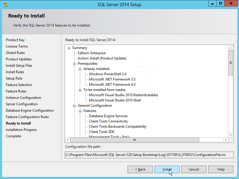
Wait for the install to finish.
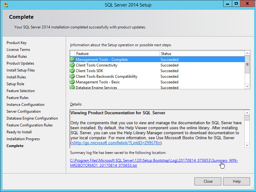
Click Close.
2.4.2 Open Port on Firewall
Open Windows Firewall with Advanced Security.
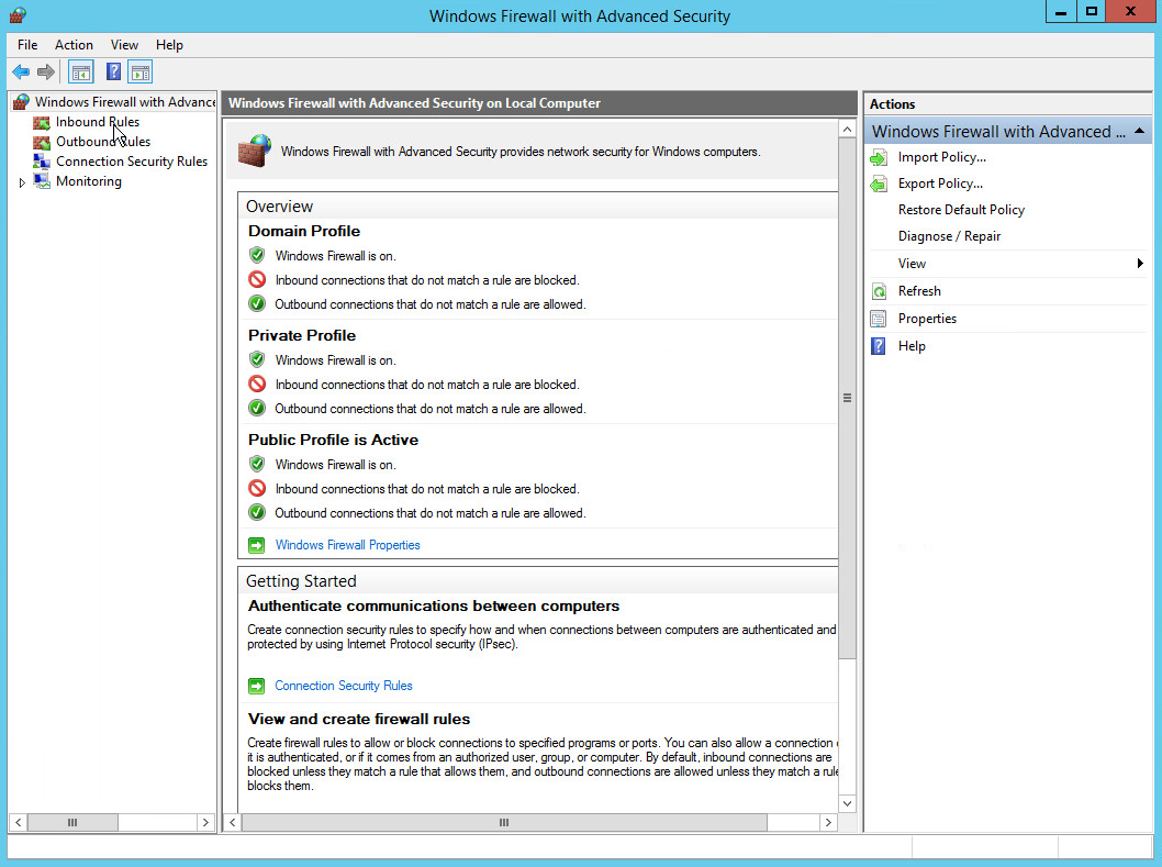
Click Inbound Rules.
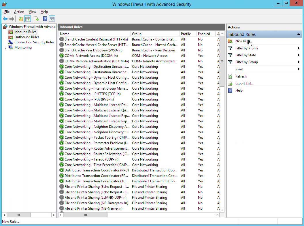
Click New Rule.
Select Port.
Click Next.
Select TCP and Specific local ports.
Type 1433 into the text field.
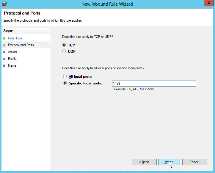
Click Next.
Select Allow the connection.
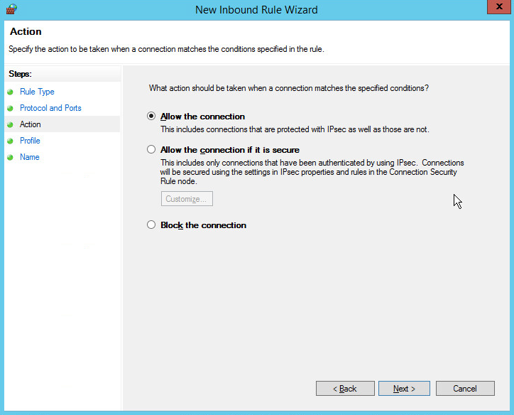
Click Next.
Select all applicable locations.
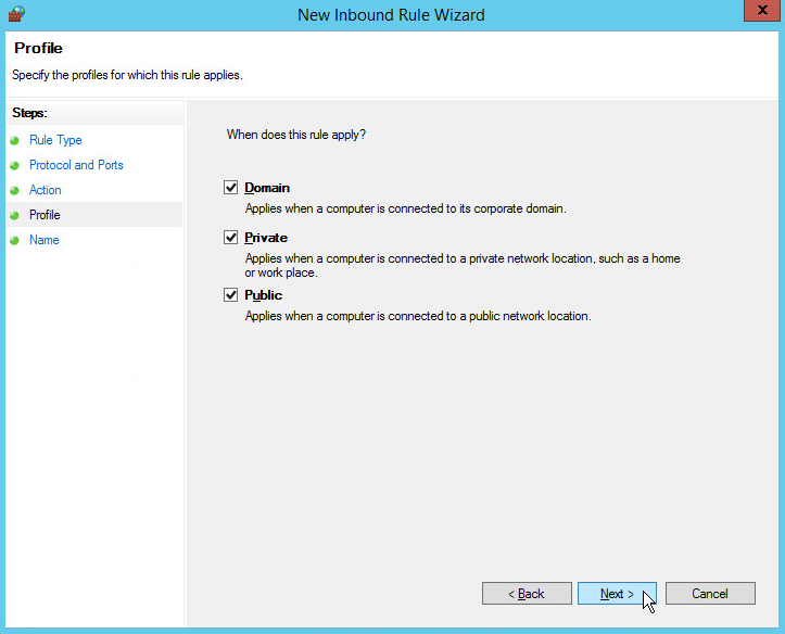
Click Next.
Name the rule Allow SQL Access.
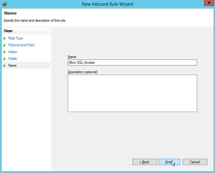
Click Finish.
2.4.3 Add a New Login to the Database
Open SQL Server Management Studio.
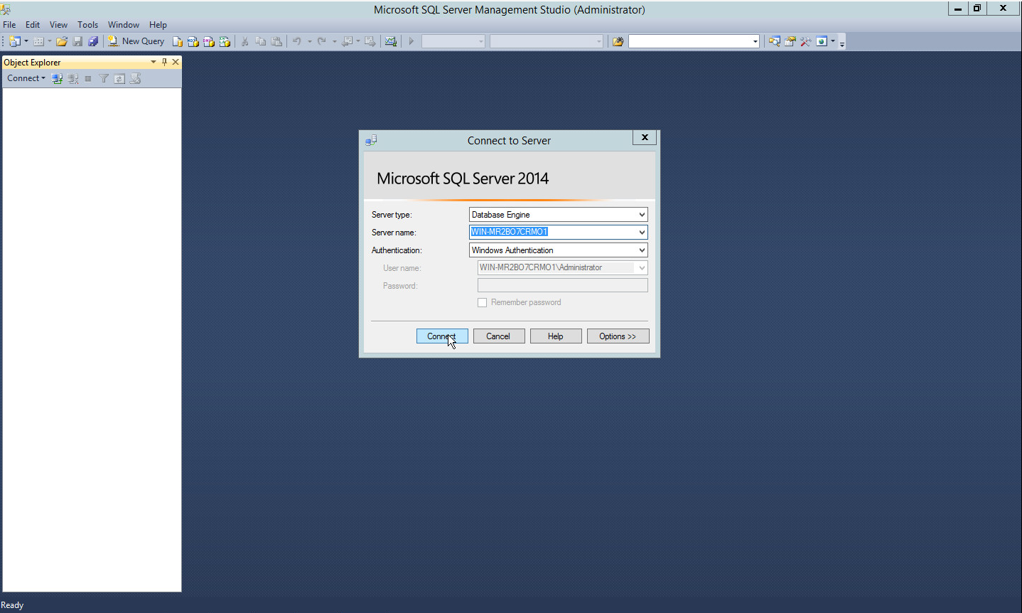
Click Connect to connect to the database.
In the Object Explorer window, expand the Security folder.
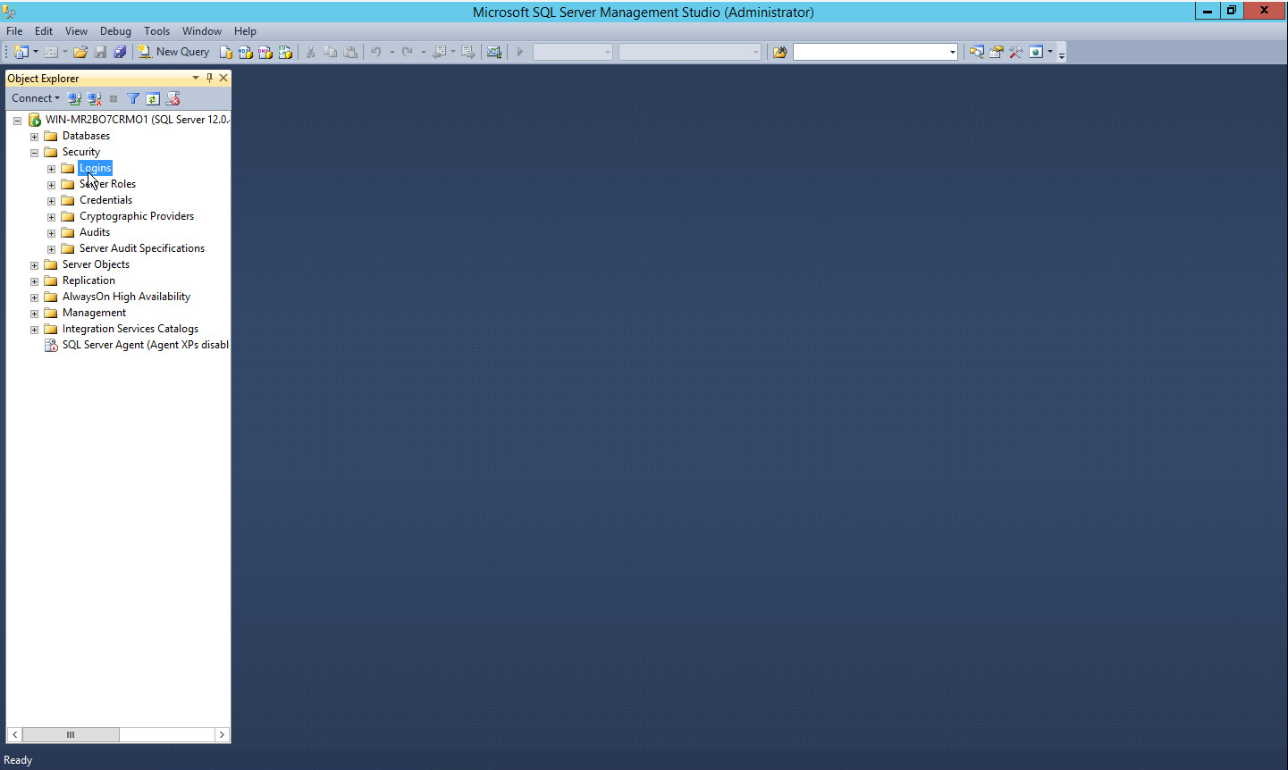
Right-click on the Logins folder and click New Login….
Input the desired user.
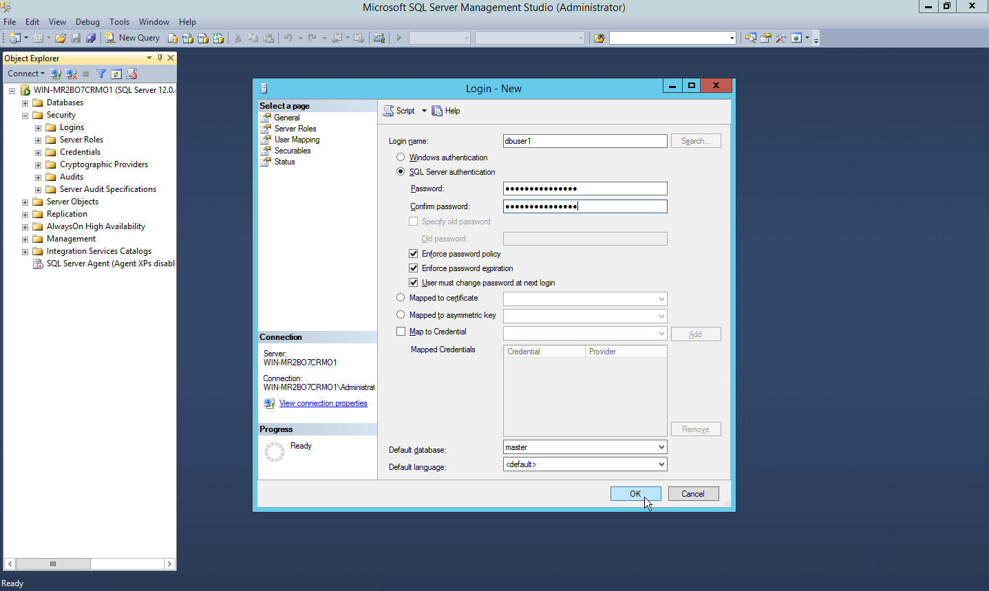
Click OK.
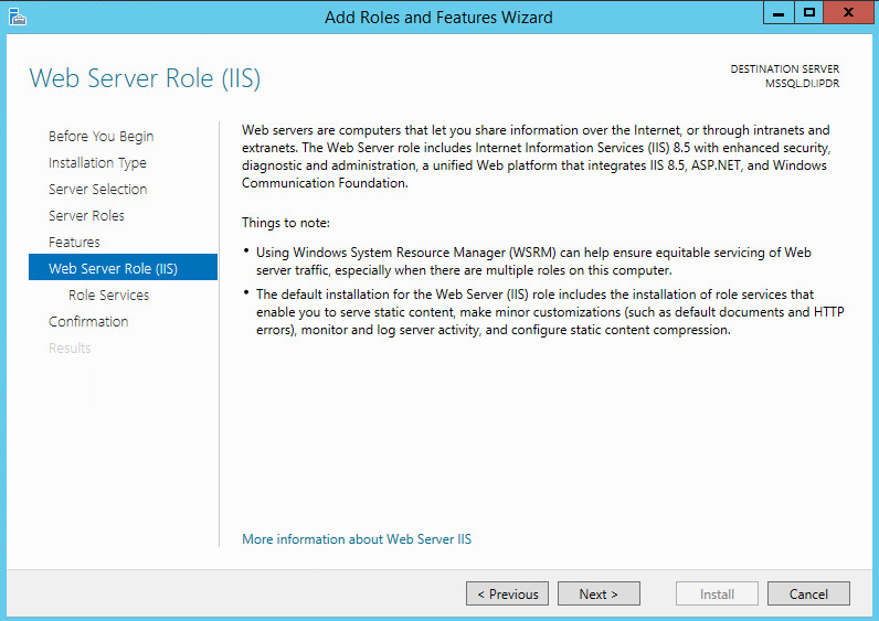
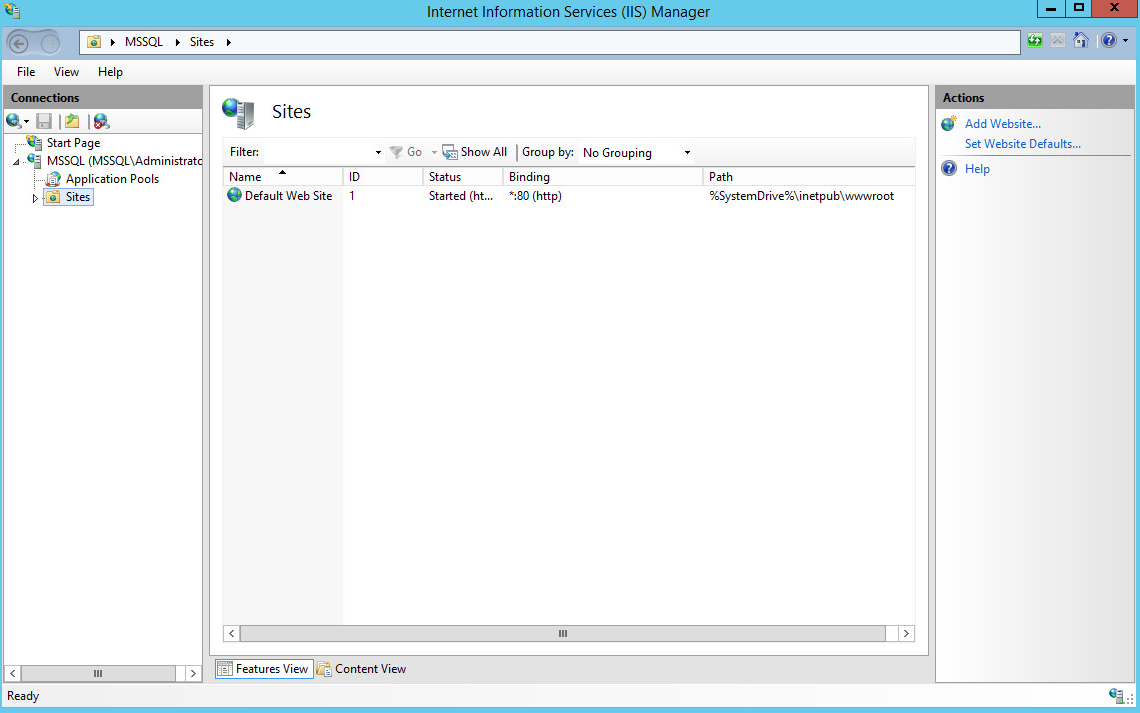
2.5 Microsoft IIS Server
As part of our enterprise emulation, we include a Microsoft Internet Information Services (IIS) server. This section covers the installation and configuration process used to set up Microsoft Exchange on a Windows Server 2012 R2 machine. This was conducted on the same machine as Section 2.4.
2.5.1 Install IIS
Open Server Manager.
Click Add Roles and Features.
Click Next.
Select Role-based or feature-based installation.
Click Next.
Select MSSQL (or the correct Windows Server name) from the list.
Click Next.
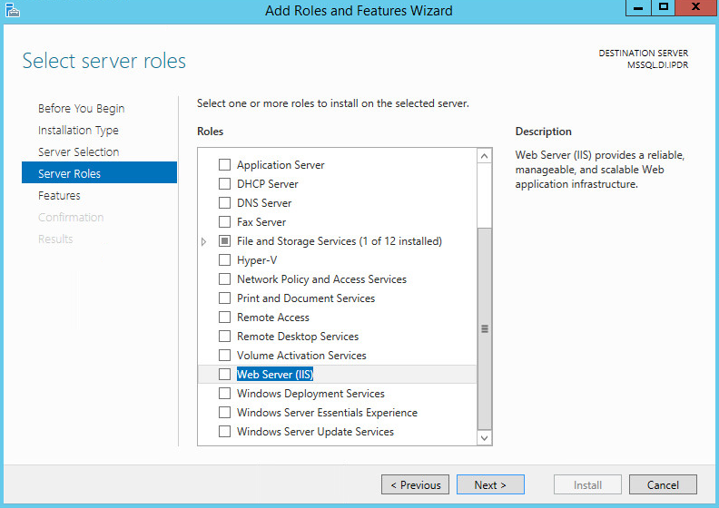
Check the box next to Web Server (IIS).
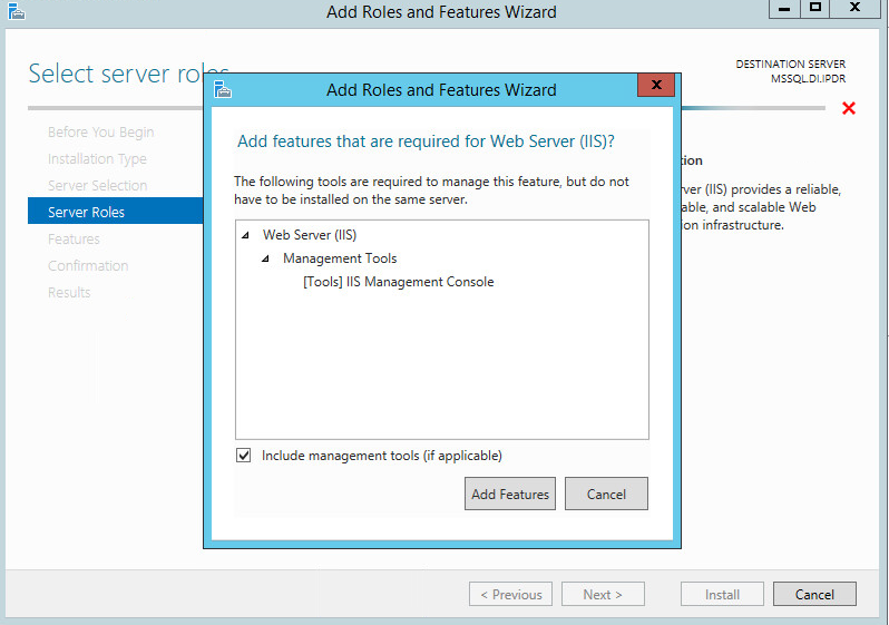
Click Add Features.
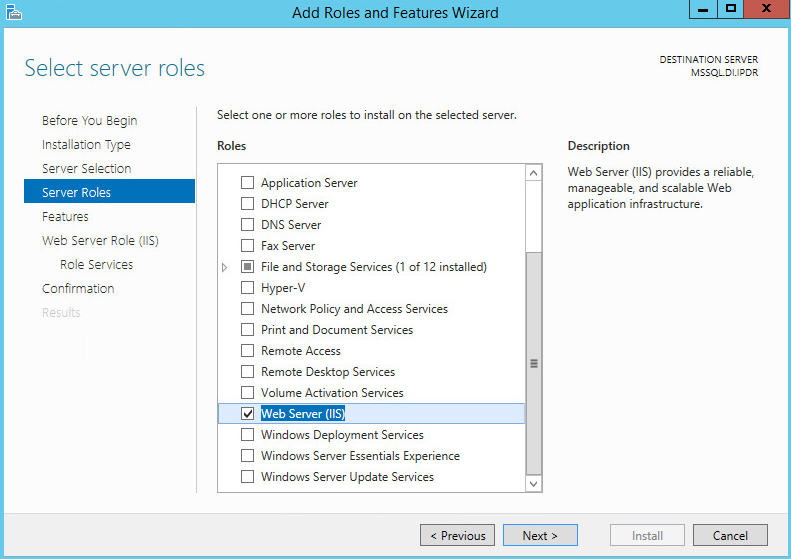
Click Next.
Ensure that all desired features are selected.
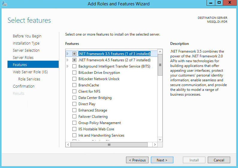
Click Next.
Click Next.
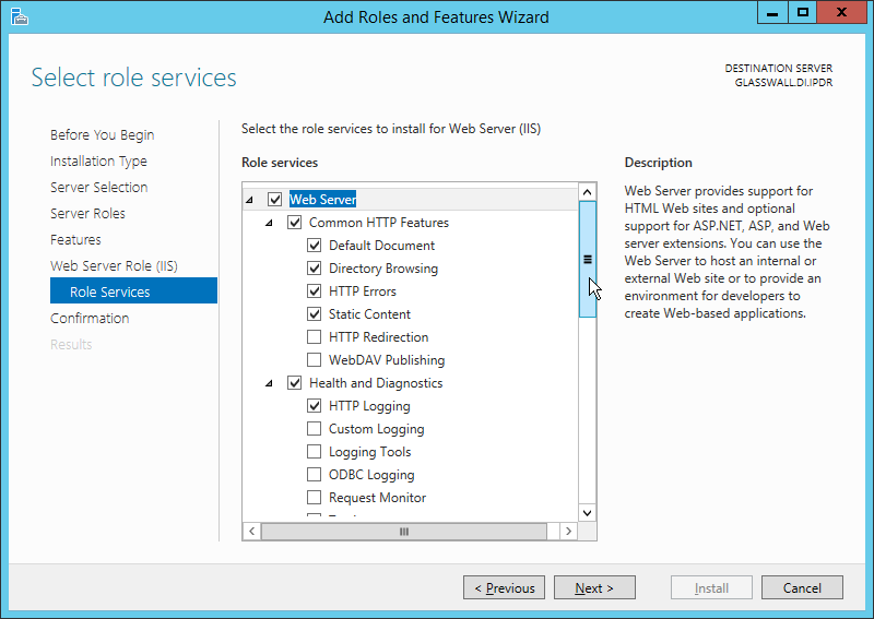
Ensure that Default Document, Directory Browsing, HTTP Errors, Static Content, HTTP Logging, and any other desired Role services are selected.
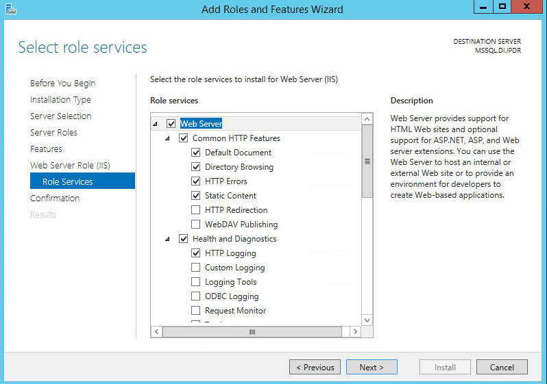
Click Next.
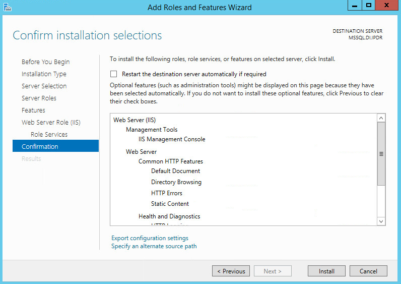
Click Install.
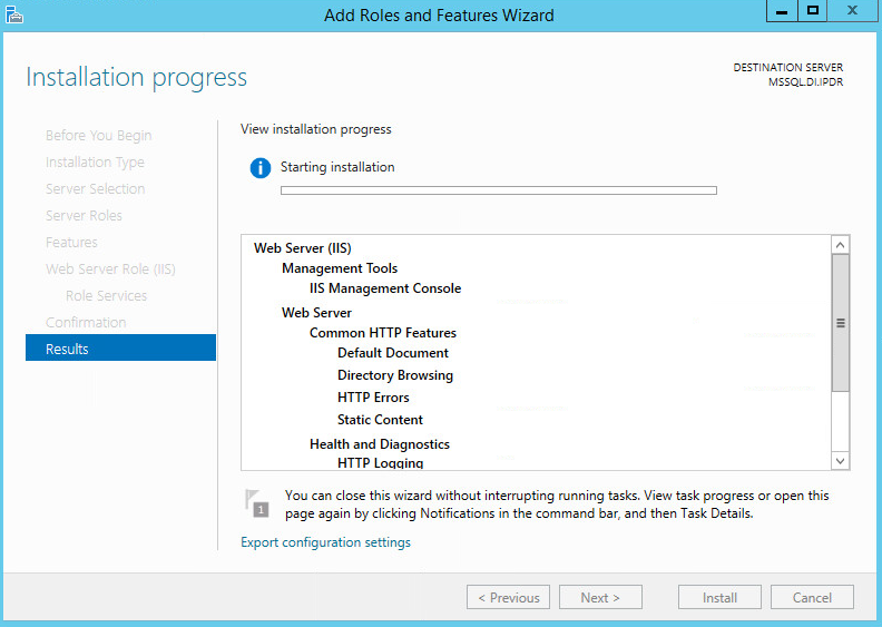
Wait for the installation to complete.
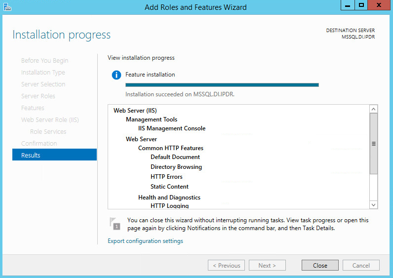
Click Close.
2.5.2 IIS Configuration
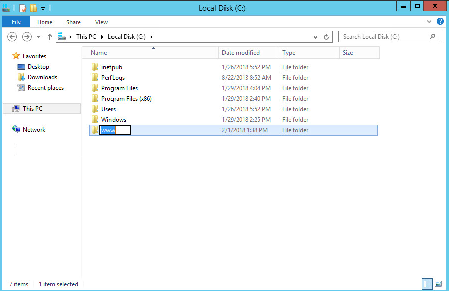
Open Windows Explorer and click This PC.
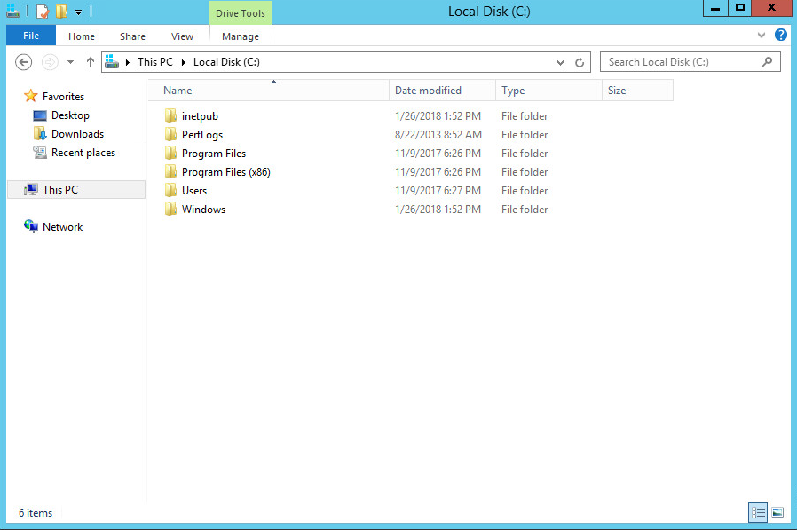
Right-click, and select Create Folder.
Name the folder www.
Open the Internet Information Services (IIS) Manager.
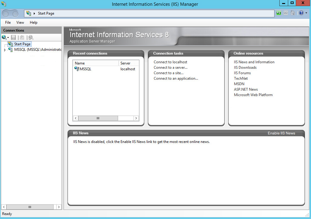
Click the arrow next to MSSQL (or the chosen name of the server).
Click Sites.
Click Add Website….
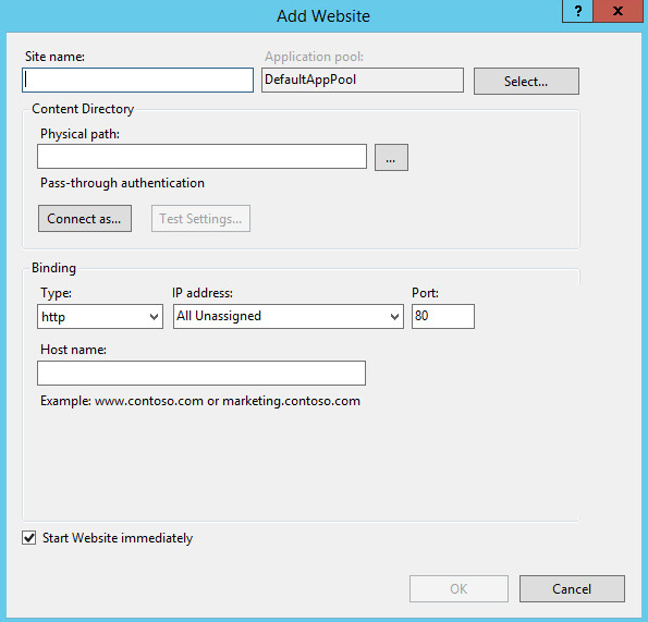
Enter the desired site name.
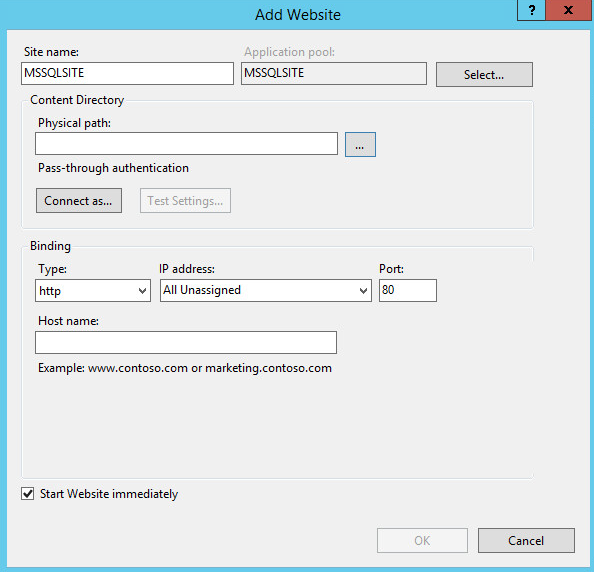
Click … under Physical path:.
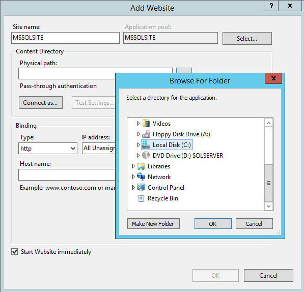
Locate and select the folder created in Step 3.
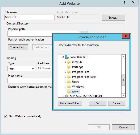
Click OK.
Set Type to http and Port to 80.
Ensure the IP address and Host name fields are filled in with the correct information for the machine.
Ensure that Start Website immediately is selected.
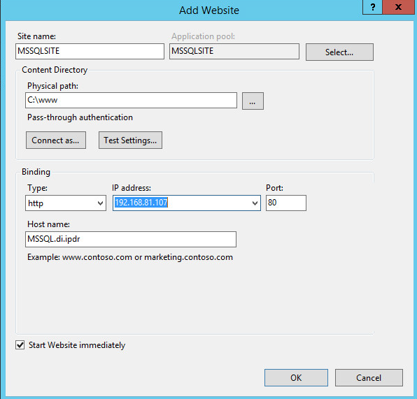
Click OK.
2.6 Semperis Directory Services Protector
This section details the installation of Semperis Directory Services Protector (DSP), a tool used for monitoring Active Directory environments. This installation requires both a copy of SQL Server Express as well as the Semperis Wizard. See the Semperis DS Protector v2.5 Technical Requirements document for specifics on the requirements. For a Windows Server 2012 R2 installation, meet the following requirements:
.NET Framework Version 3.5 SP1
.NET Framework Version 4.5.2 or later
Joined to the Active Directory Domain it is protecting
Either the installer for SQL Express Advanced or connection information and credentials for a full version of Microsoft SQL (MSSQL)
2.6.1 Configure Active Directory for Semperis DSP
Open Active Directory Users and Computers.
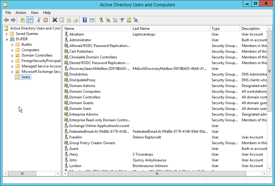
Right-click Users in the left pane, and select New > User.
Enter the information for a new user for the DSP service.
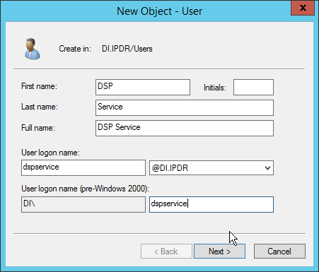
Click Next.
Enter a password twice for this user.
Set the password policy.
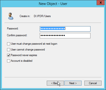
Click Next.
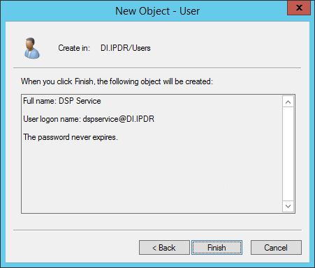
Click Finish.
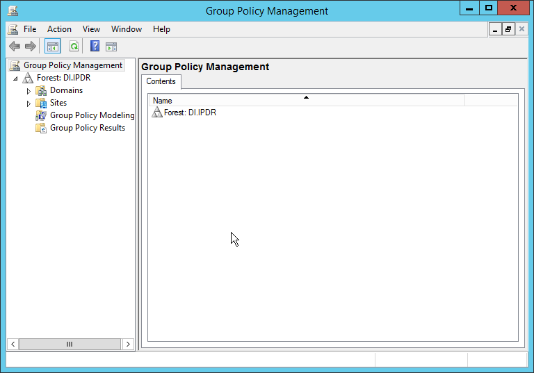
Open Group Policy Management.
Right-click Domains > DI.IPDR > Domain Controllers > Default Domain Controllers Policy, and click Edit.
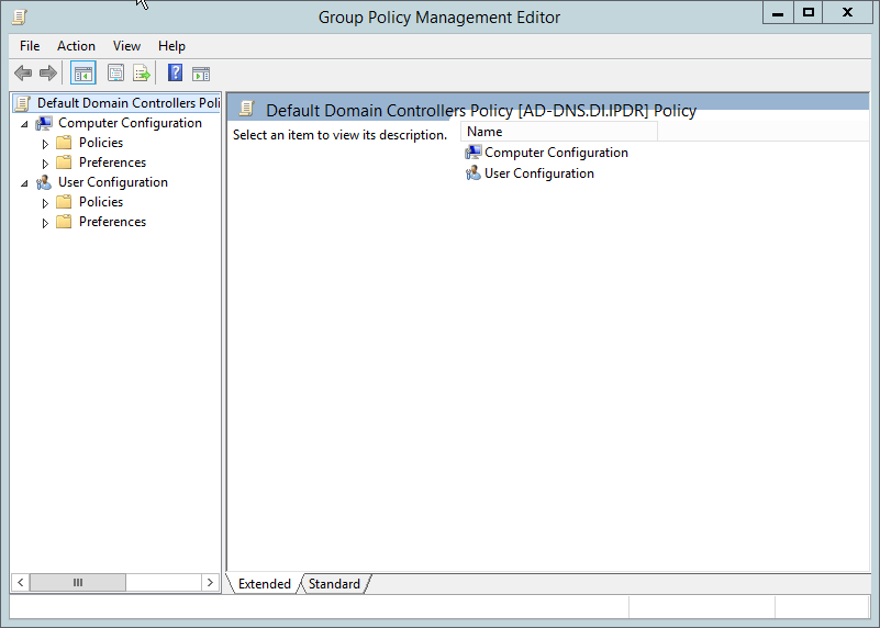
Navigate to Computer Configuration > Policies > Windows Settings > Security Settings > Advanced Audit Policy Configuration > Audit Policies > Account Management.
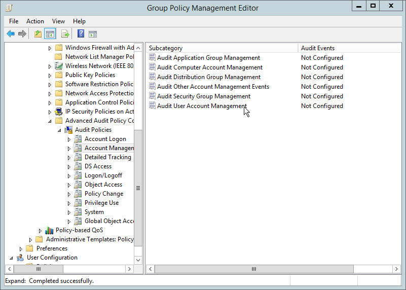
Edit the Audit User Account Management field by double-clicking it.
Check the box next to Configure the following audit events.
Check the box next to Success.
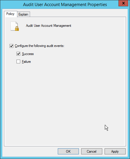
Click OK.
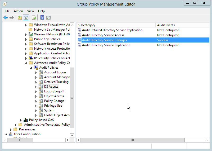
Go to Audit Policies > DS Access.
Double-click Audit Directory Services Changes.
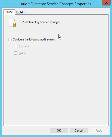
Check the box next to Configure the following audit events.
Check the box next to Success.
Click OK.
Open Active Directory Users and Computers.
Ensure View > Advanced Features is enabled.
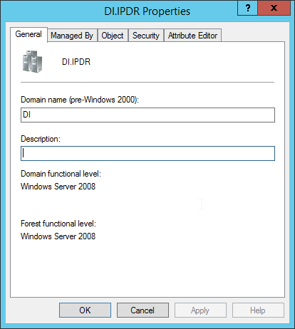
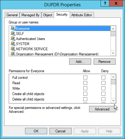
Right-click the domain (for example, DI.IPDR) created earlier, and click Properties.
Click the Security tab.
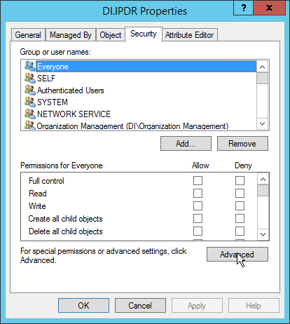
Click Advanced.
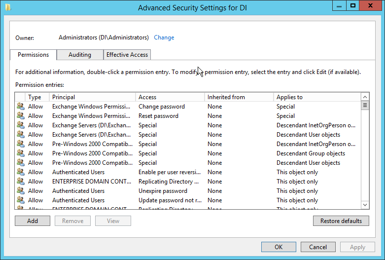
Click the Auditing tab.
Click Add.
Enter Everyone.
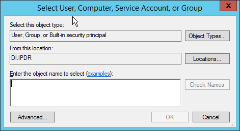
Click OK.
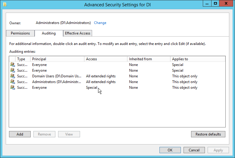
Double-click Everyone.
Check the boxes next to Write all properties, Delete, Delete subtree, Modify permissions, Modify owner, All validated writes, All extended rights, Create all child objects, Delete all child objects.
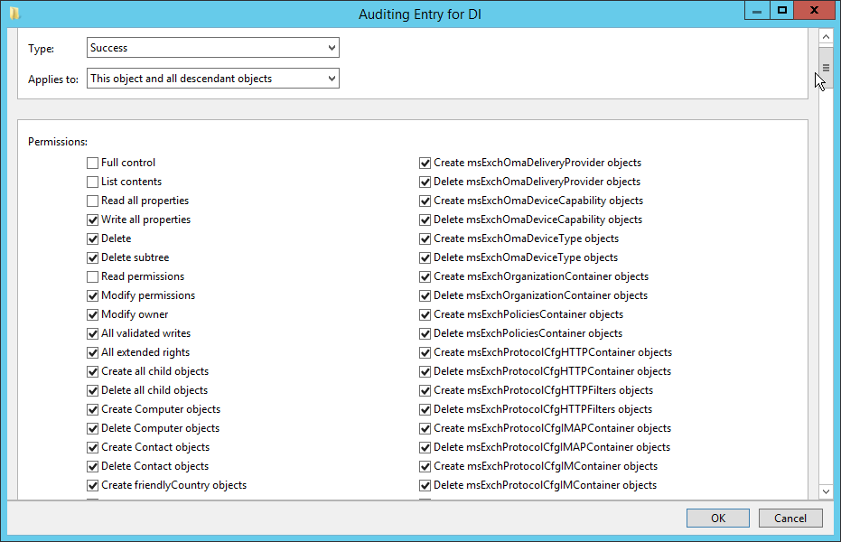
Click OK.
Click OK.
2.6.2 Install Semperis DSP
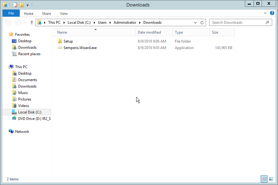
If you are using a local SQL Express Advanced server, place the SQLEXPRADV_x64_ENU.exe installer in a directory called Setup, and ensure that the Semperis Wizard is adjacent to the Setup folder (not inside it). If a SQL Express Advanced server is not being used, no Setup folder is required.
If prompted to restart the computer, do so.
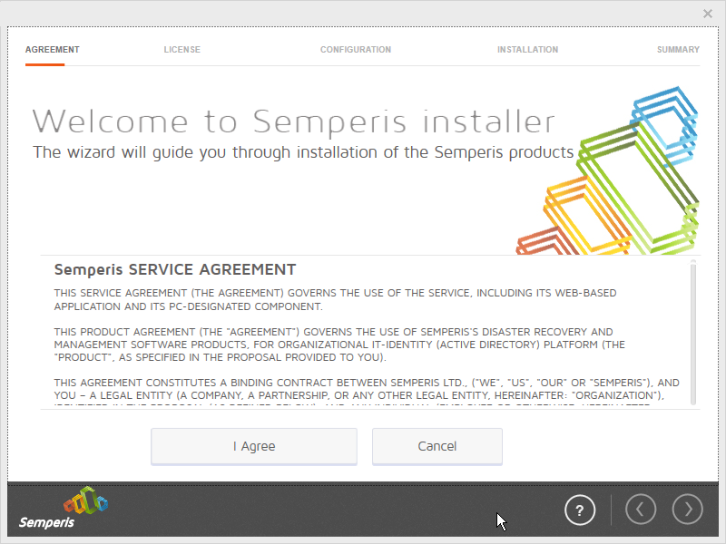
Click I Agree.
Select Evaluation License.
Select Active Directory State Management.
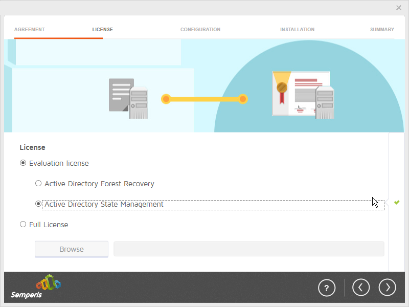
Click the > button.
Enter the username and password of the account created earlier.
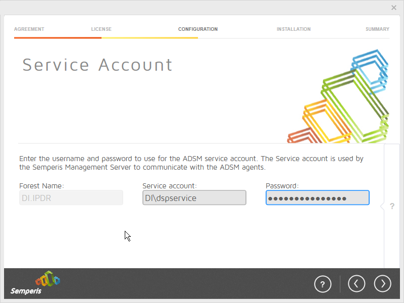
Click the > button.
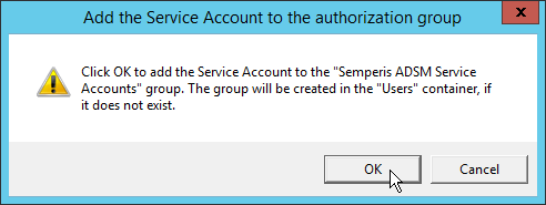
Click OK.
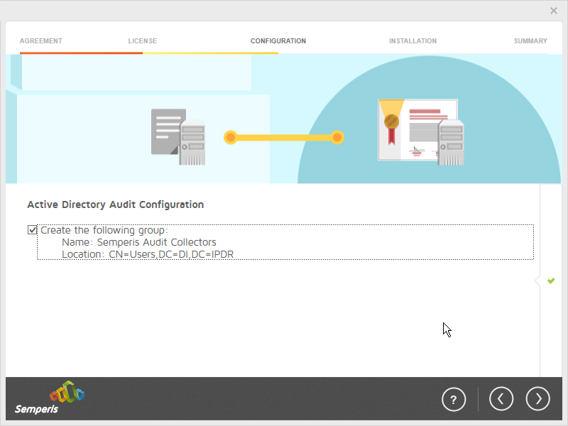
Check the box next to Create the following group.
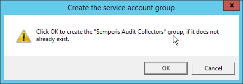
Click OK.
Click the > button.
Select the appropriate database option, and enter any required information.
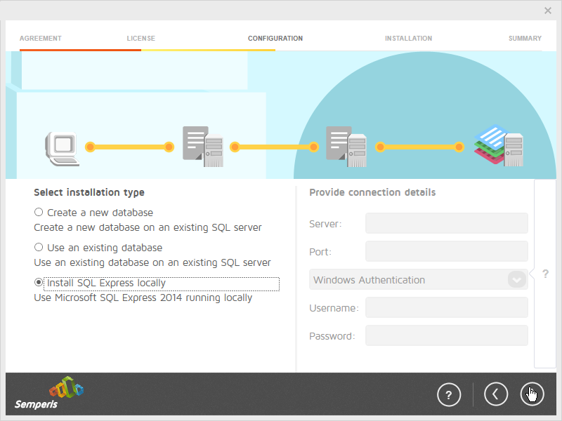
Click the > button.
Click OK.
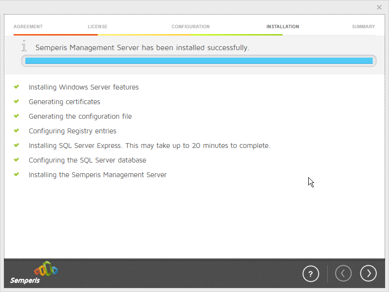
Click the > button after the installation completes.
There should now be a shortcut on the desktop linking to the web console for Semperis DS Protector.
On the login page, enter the full domain as well as the NetBIOS name.
Enter the username and password of an administrator on the domain.
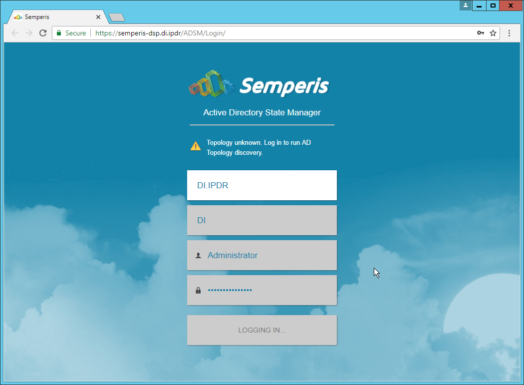
Click Login.
Check the box next to the domain controllers that should be monitored by DSP.
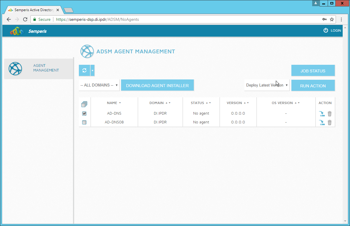
Click Run Action.
Enter the password for the account.
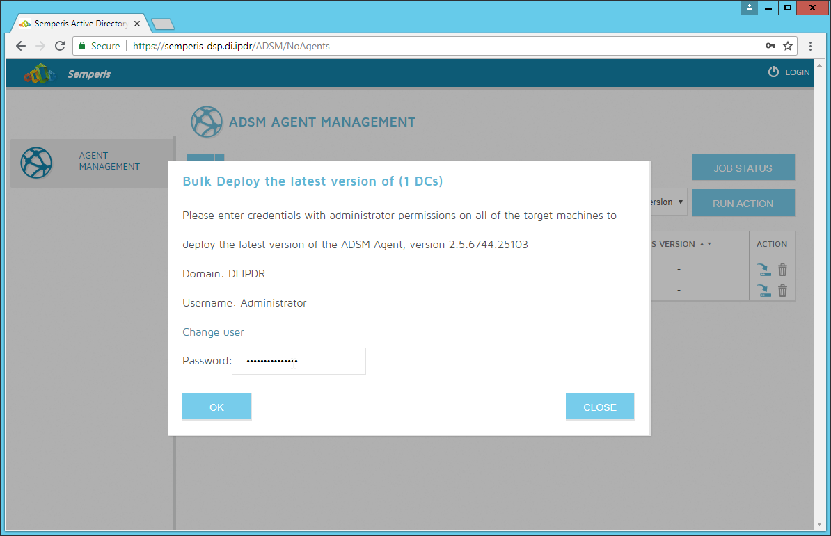
Click OK.
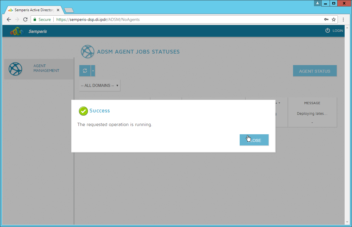
Click Close.
After the agent finishes deploying, click Login at the top of the page, and log in.
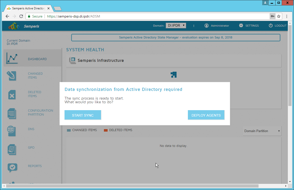
Click Start Sync.
After this completes, click Settings at the top of the page.
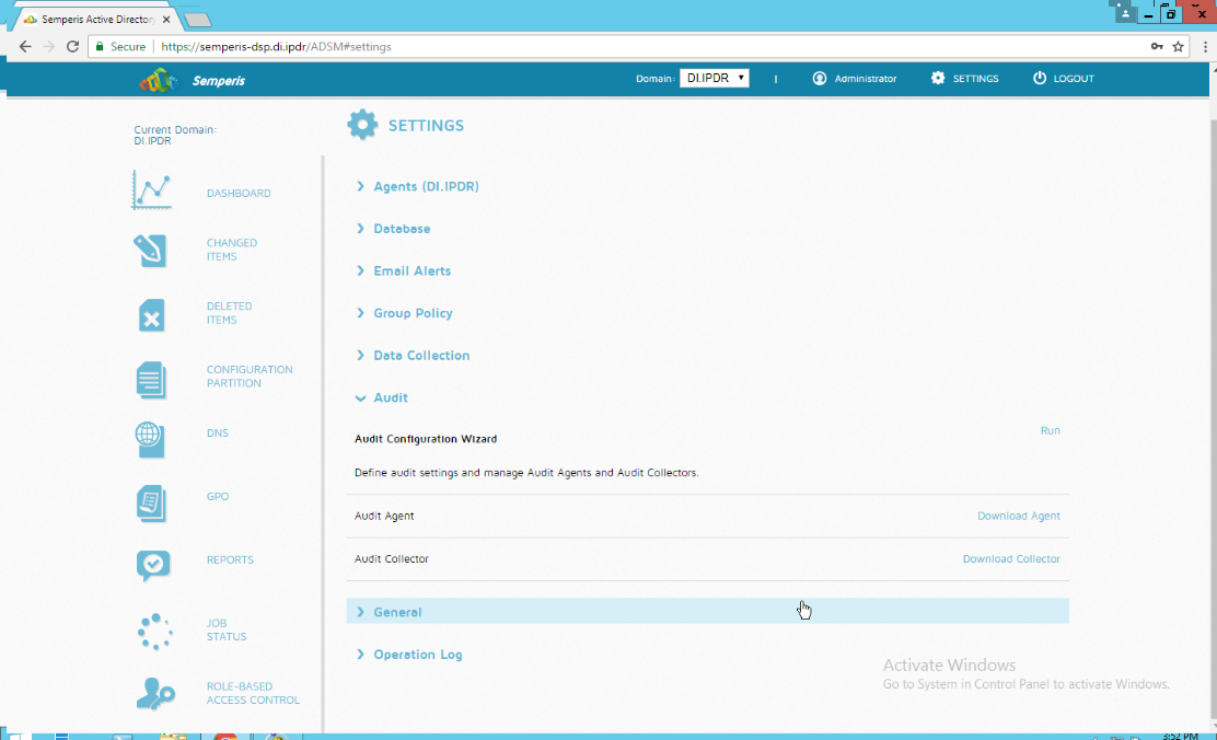
Click Audit.
Click Run.
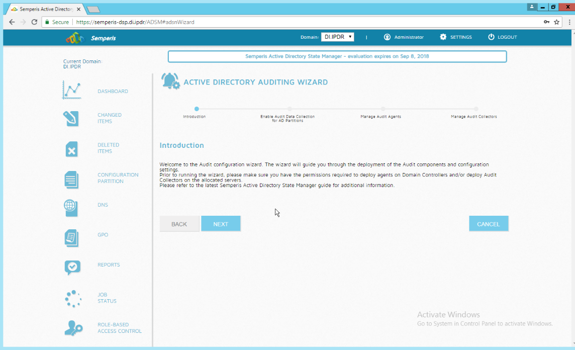
Click Next.
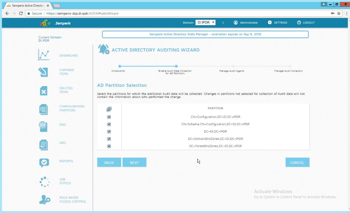
Click Next.
Check the boxes next to any Domain Controllers that should be monitored.
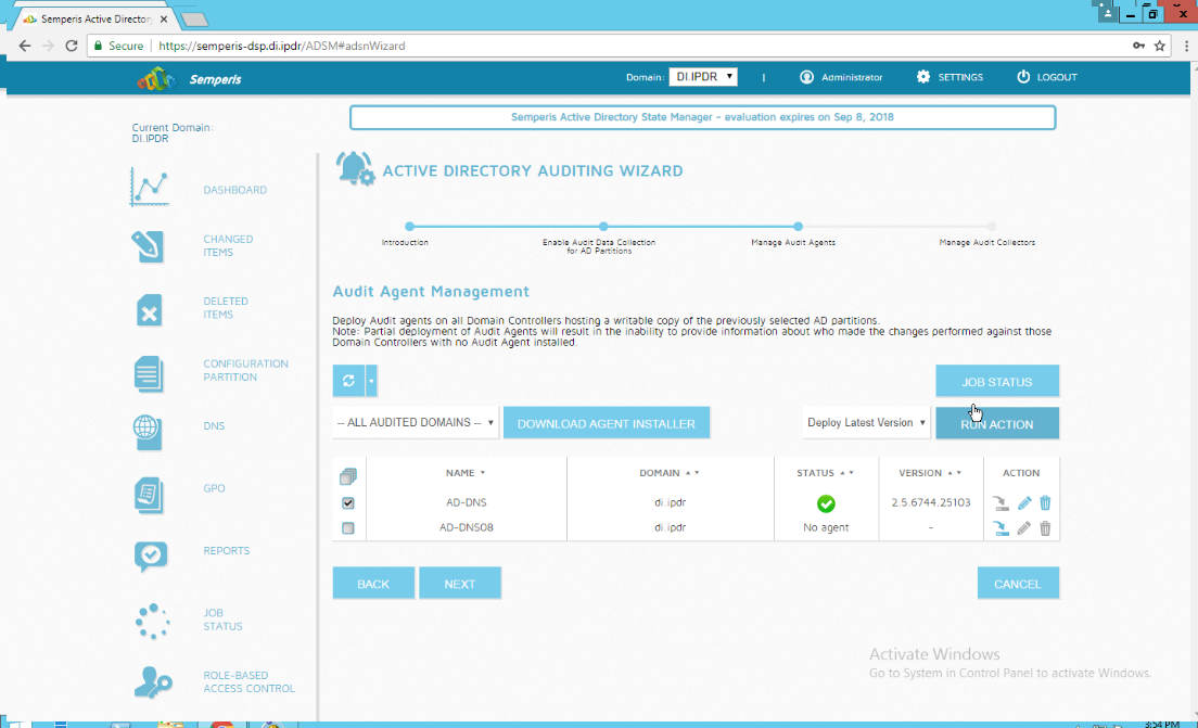
Click Run Action.
Enter the password.
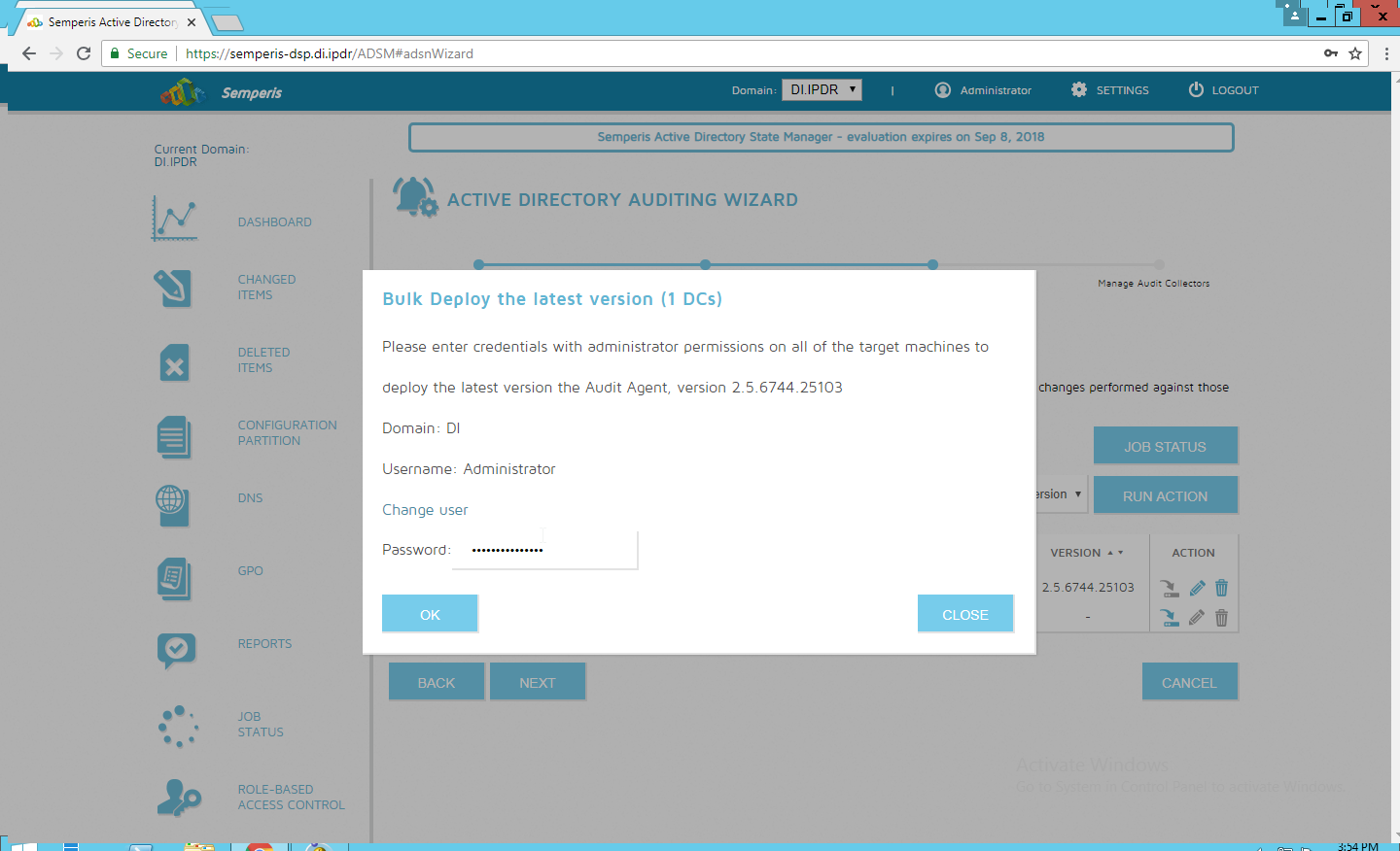
Click OK.
Wait for the deployment to finish.
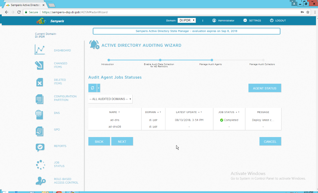
Click Next.
Click Finish.
2.6.3 Roll Back Changes with Semperis DSP
Go to Changed Items on the left navigation bar.
Check the box next to any undesired Active Directory changes.
Click the … button to view more details about the change.
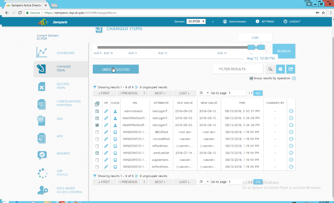
Click Undo Selected to roll back these changes.
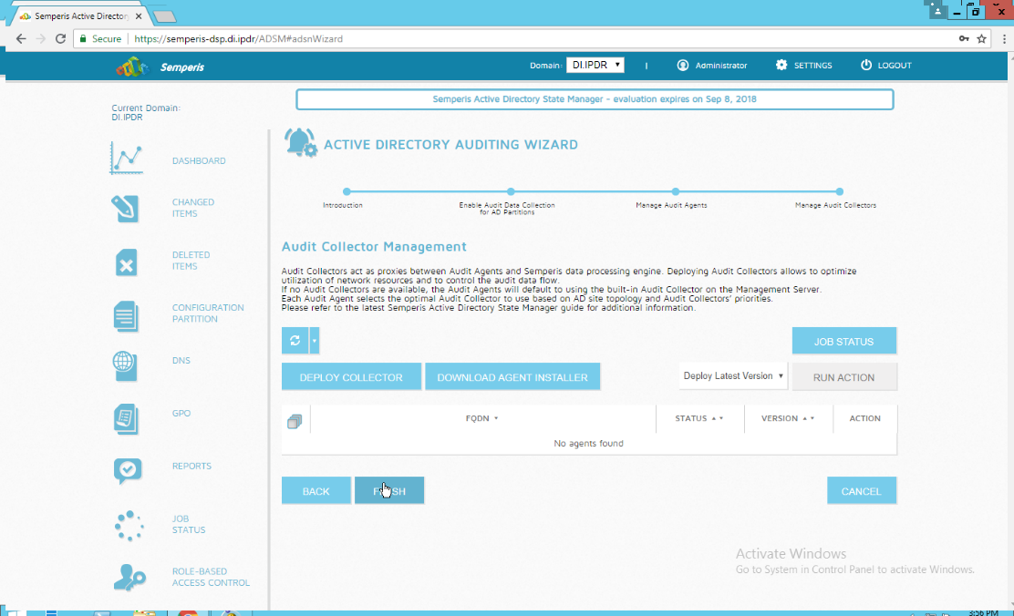
2.6.4 Configure Reporting with Semperis DSP
Click Reports on the left sidebar in the Semperis DSP web console.
Under Generate Report, reports can be viewed instantly, by selecting a type of report and clicking Create.
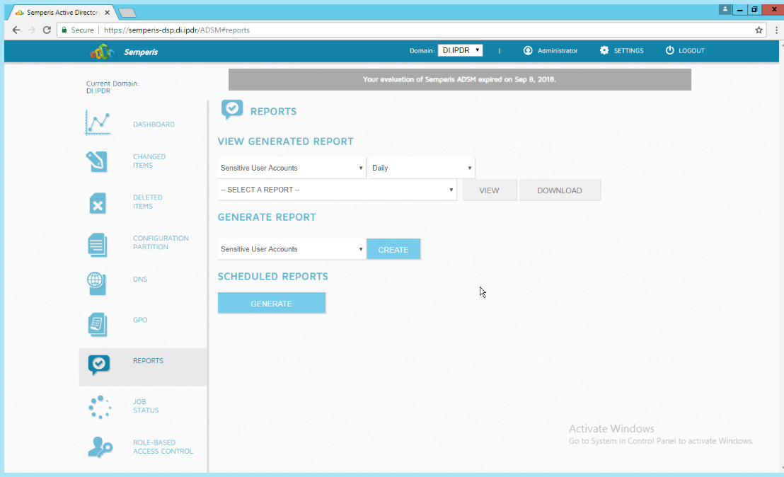
Under Scheduled Reports, click Generate to automatically email specific reports.
Select a report type and a schedule.
Enter the email addresses of anyone who should receive this report.
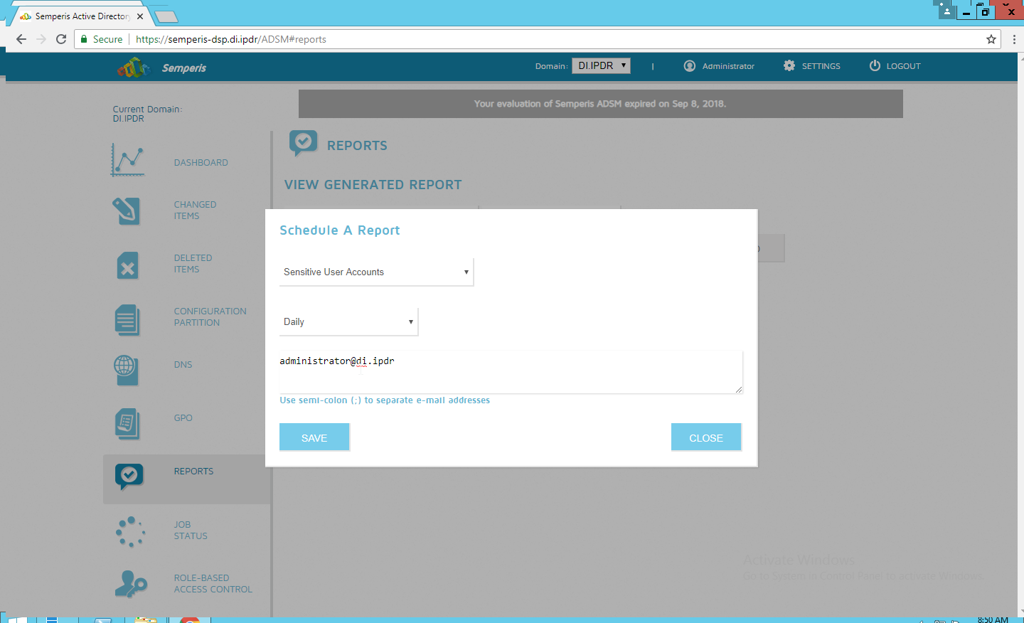
Click Save.
2.6.5 Configure Email Alerts with Semperis DSP
Click Settings on the Semperis DSP web console.
Expand the Email Alerts section.
Click Edit.
Enter the information of the organization’s email server as well as an email address from which to send.
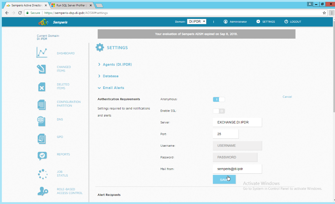
Click Save.
Enter an email address to which to send a test email.
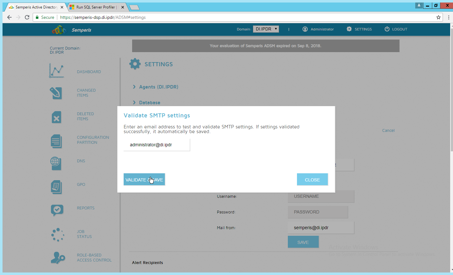
Click Validate & Save.
Under Alert Recipients, add any desired recipients of alerts.
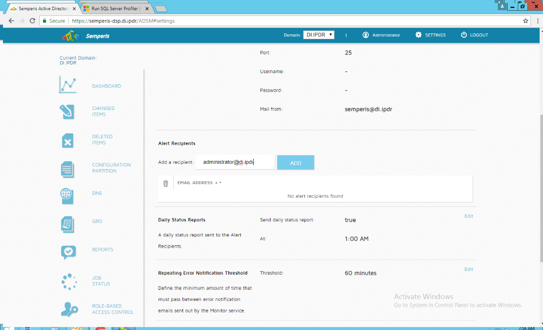
Click Add.
Configure any schedule settings according to your organization’s needs.
2.7 Glasswall FileTrustTM for Email
The following sections will detail the installation of Glasswall FileTrustTM for Email, an email security product, on a new Windows 2012 R2 machine. For the purposes of this guide, we use Microsoft Exchange as the email service provider.
2.7.1 Install Prerequisites
2.7.1.1 Install the IIS web server
In Server Manager, click Add Roles and Features.
Click Next.
Select Role-based or feature-based installation.
Click Next.
Select the current server.
Click Next.
Select Web Server (IIS).
Click Next.
Select .NET Framework 4.5 Features.
Click Next.
Select the following Role Services: Web Server, Common HTTP Features, Default Document, Directory Browsing, HTTP Errors, Static Content, Health and Diagnostics, HTTP Logging, Performance, Static Content Compression, Security, Request Filtering, Client Certificate Mapping Authentication, Application Development, .NET Extensibility 4.5, ASP.NET 4.5, ISAPI Extensions, ISAPI Filters, Management Tools, and IIS Management Console.
Click Next.
Check the box next to Restart the destination server automatically if required.
Click Install.
2.7.1.2 Install Microsoft SQL 2014 Enterprise
Please see Section 2.4 for an installation guide for MS SQL 2014; for simplicity it should be installed on the same server as Glasswall FileTrust. Ensure that Mixed Mode authentication is selected when installing.
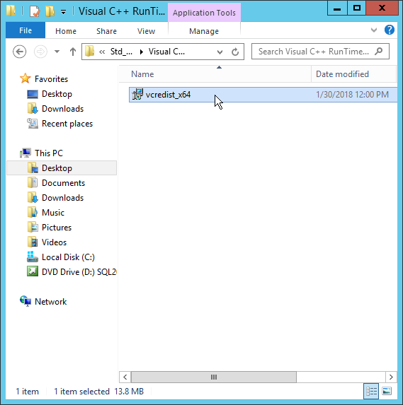
2.7.1.3 Install Microsoft Visual C++ 2015
Run the vcredist_x64 installer.
Check the box next to I agree to the license terms and conditions.
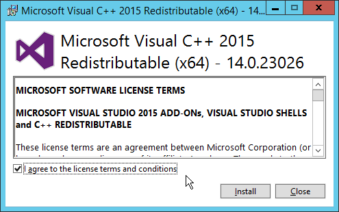
Click Install.
After the installation is complete, click Close.
2.7.2 Install the Glasswall FileTrust Server Component
2.7.2.1 Install Glasswall Hub
Run HubInstaller.msi.
Click Next.
Check the box next to I accept the terms in the License Agreement.
Click Next.

Click Next.
Enter localhost for the Database Server.
Enter HubDatabase for the Database Name.
Enter a username and password (and take note of these for later).
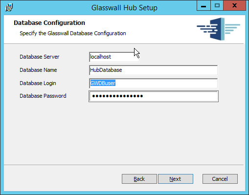
Click Next.
Select Windows Authentication.
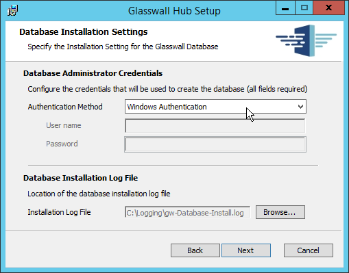
Click Next.
Replace the domain of the management service URL with the address of the current machine, such as glasswall.di.ipdr.
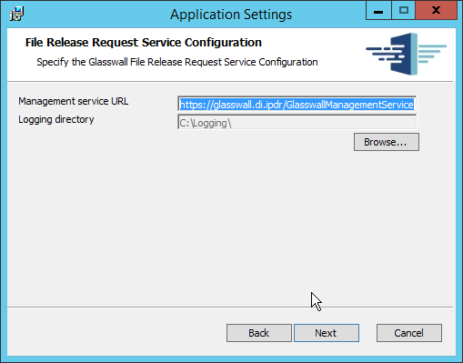
Click Next.
Click Install.
Click Finish.
2.7.2.2 Install Glasswall Integration Service
Run GlasswallIntegrationService.msi.
Click Next.
Check the box next to I accept the terms in the License Agreement.
Click Next.
For Database Server, Database Name, Database User, and Database Password, enter the information entered in the Glasswall Hub Installer.
Create a username and password for API User Name and API Password.
Enter an email address to be used for notifications in Notifications Smtp Mail From.
Enter the address for the mail server for Notifications Smtp Host.
Enter a port (25 is used here) for Notifications Smtp Port.
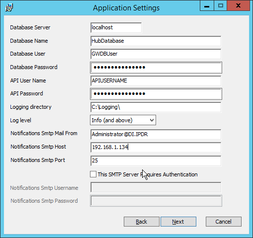
Click Next.
Click Install.

Click Finish.
2.7.2.3 Install Glasswall Administrator Console
Run AdministratorConsoleInstaller.msi.

Click Next.
Check the box next to I accept the terms in the License Agreement.
Click Next.
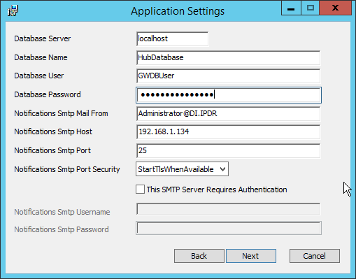
For Database Server, Database Name, Database User, and Database Password, enter the information entered in the Glasswall Hub Installer.
For Notifications Smtp Mail From, Notifications Smtp Host, Notifications Smtp Port, enter the information entered in the Glasswall Integration Service Installer.
For Notifications Smtp Port Security, select StartTlsWhenAvailable.
Click Next.
Click Install.
Click Finish.
2.7.2.4 Add the Server’s Certificate
For the purposes of this build, a self-signed certificate is used, but this is dependent on the needs of the organization. Ensure that the certificate used is issued to the domain, such as *.di.ipdr.
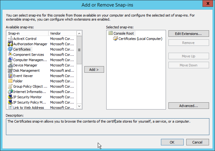
Open mmc.
Click File > Add/Remove Snap-In….
Select Certificates from the left pane, and click Add.
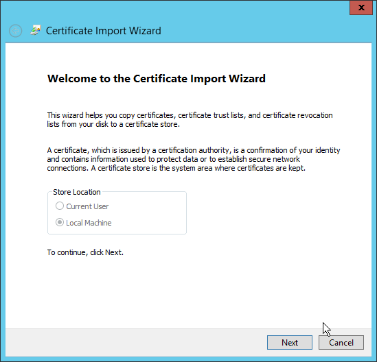
Select Computer Account.
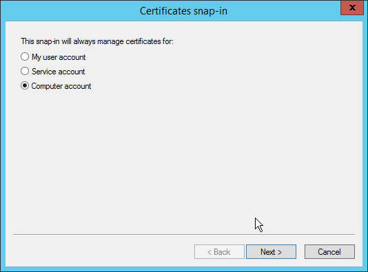
Click Next.
Select Local computer.
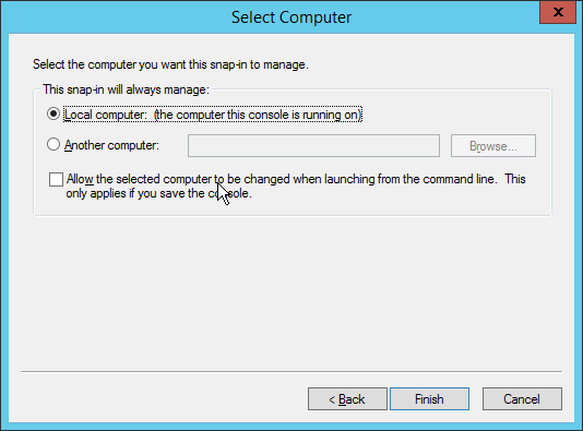
Click Finish.
Click OK.
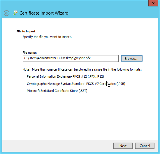
Right-click the Personal certificate store, and select All tasks > Import….

Enter the file name of the certificate.
Click Next.
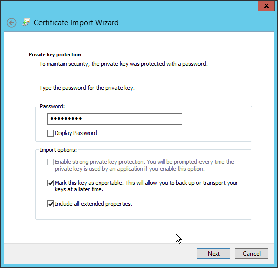
Enter the password for the certificate.
Check the box next to Mark this key as exportable.
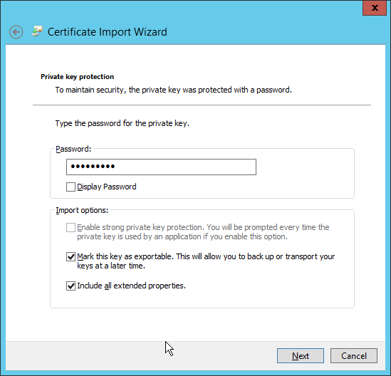
Click Next.
Ensure that the Certificate store says Personal.
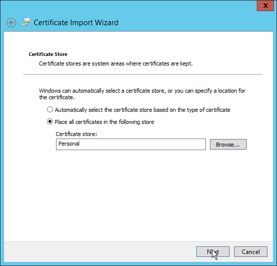
Click Next.

Click Finish.
Re-open the certificate import wizard but this time for Trusted Root Certification Authorities.
Click Next.
Select the same certificate.
Click Next.
Enter the certificate’s password.
Check the box next to Mark this key as exportable.
Click Next.
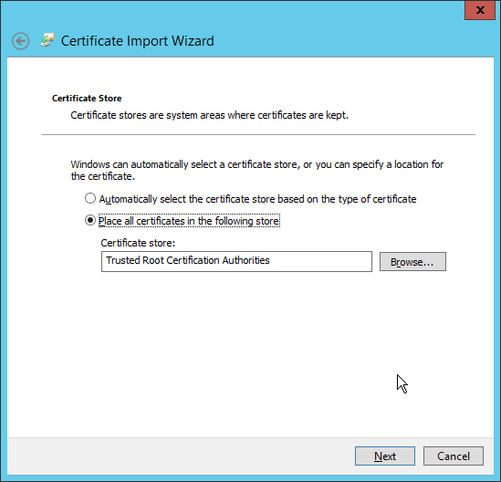
Click Next.
Click Finish.
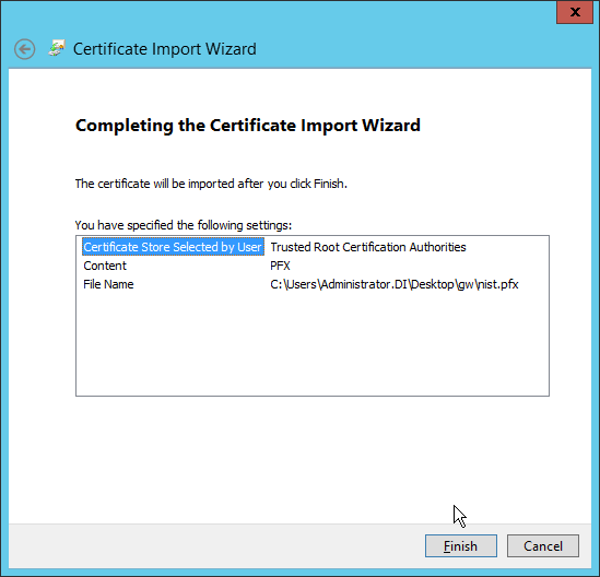
Open the Certificate Import Wizard again for the Personal store.
Click Next.
Browse to the GlasswallLicenseValidation certificate.
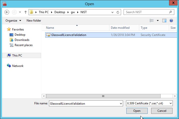
Click Open.
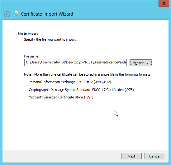
Click Next.

Click Next.
Click Finish.
Open IIS Manager by right-clicking the server in Server Manager.
Navigate to the Default Website in the tree.
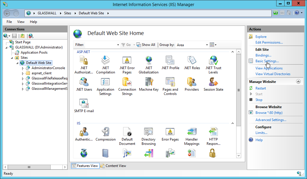
Click Bindings on the right sidebar.
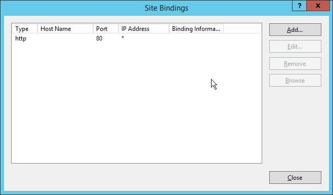
Click Add.
Select https for the Type.
Select All Unassigned for IP address.
Select the domain certificate for SSL certificate.
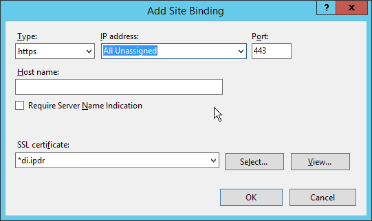
Click OK.
Select the http binding.
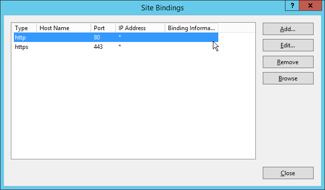
Click Remove.
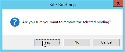
Click Yes.
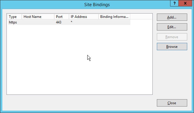
Click Close.
Restart the IIS server. The Glasswall FileTrust console should now be accessible through a browser. (For example, https://glasswall.di.ipdr/AdministratorConsole). Ensure that there are no certificate errors.
2.7.2.5 Install the Smtp Analysis Agent
Run SmtpAnalysisAgentInstaller.msi.
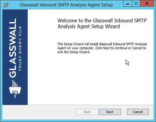
Click Next.
Check the box next to I accept the terms in the License Agreement.
Click Next.
For Listening port, enter 25.
For Management service URL, correct the domain to be the web domain of the IIS server (for example, glasswall.di.ipdr).
For the Relay endpoints, enter the address of the Exchange server, followed by the port (for example, exchange.di.ipdr:25).
For the TLS certificate thumbprint, enter the value from the thumbprint field on the certificate, without any spaces.
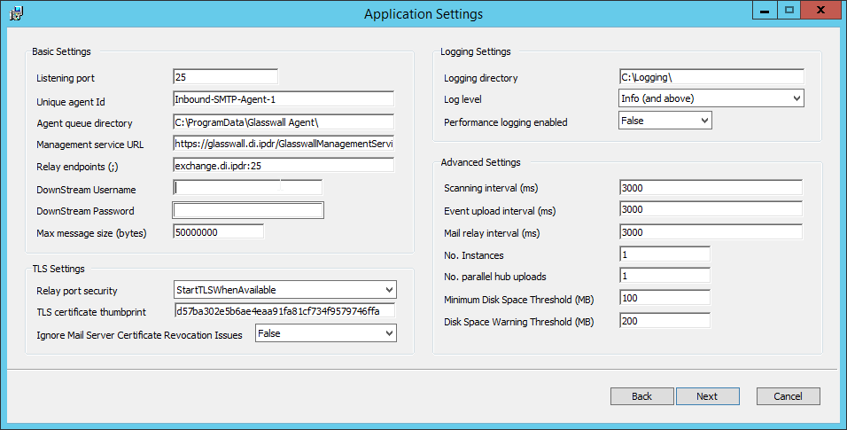
Click Next.
Click Install.
Click Finish.
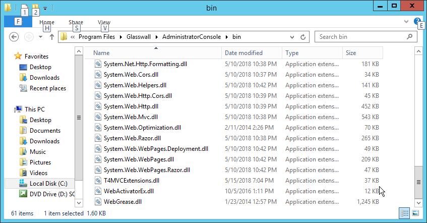
2.7.2.6 Distribute the Glasswall License File
Copy the Glasswall License file to the following locations, assuming Glasswall was installed to C:/Program Files/Glasswall.
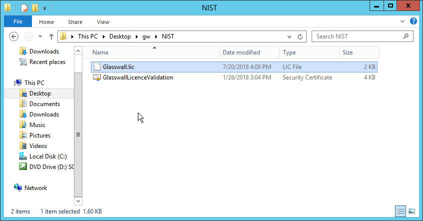
First copy it to C:/Program Files/Glasswall/ManagementService/bin.
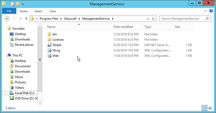
Then copy it to C:/Program Files/Glasswall/InboundSmtpAnalysisAgent.
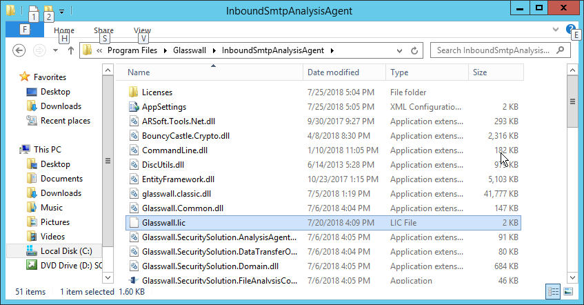
Lastly copy it to C:/Program Files/Glasswall/AdministratorConsole/bin.
2.7.3 Configure Glasswall FileTrust
Please see https://docs.glasswallsolutions.com/cloud/Content/Configuring/Office365-Integration.htm for an example configuration that routes email with attachments from Office365 to Glasswall FileTrust. Glasswall then forwards email back to Office365, after processing. Note that this linked configuration does not work with on-premise Exchange setups.
Instead, to achieve the goal of routing email through Glasswall, we redirect local mail exchange (MX) records to Glasswall FileTrust. We implemented it this way because of limitations of the lab environment, but organizations should consult with the vendor for the best solution to route email through the email sanitization component, as other options may be available depending on the enterprise.
2.7.3.1 Create a New Administrator Account
Open Task Manager.
In the Services tab, start the InboundSmtpAnalysisAgent service.
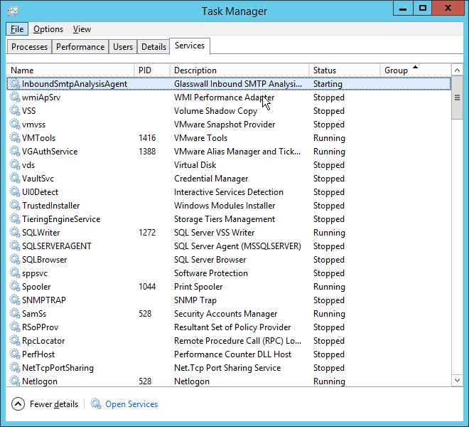
Close Task Manager.
Open a browser and navigate to the Glasswall Administration Console (for example, http://glasswall.di.ipdr/AdministratorConsole).
If this is the first time logging in, the default account will be admin@glasswallsolutions.com, and the password is Welcome1? .
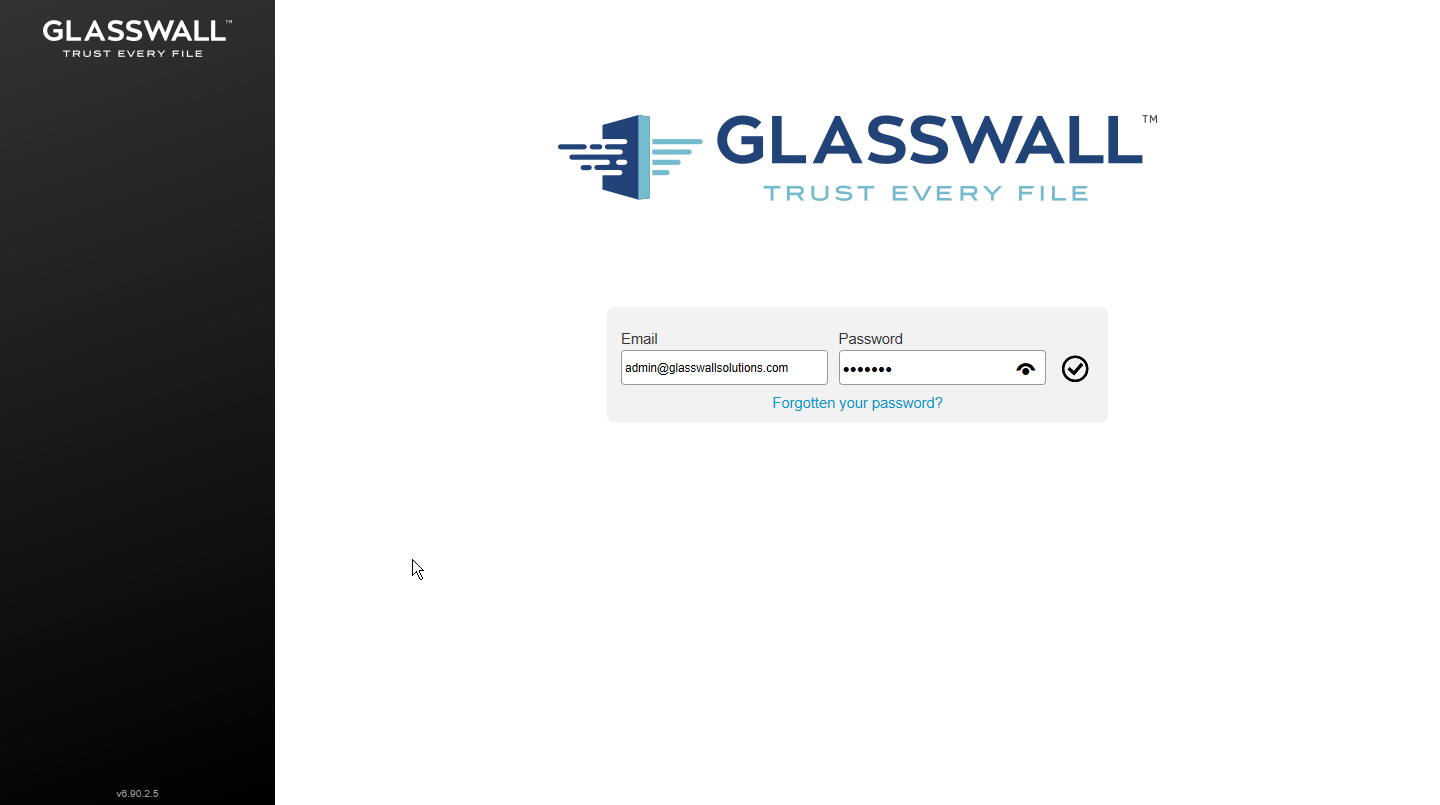
Log in using these credentials.
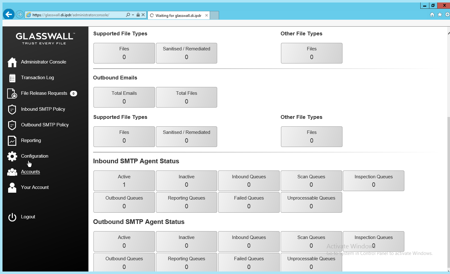
On the left sidebar, click Accounts.
Under Accounts, click Add.
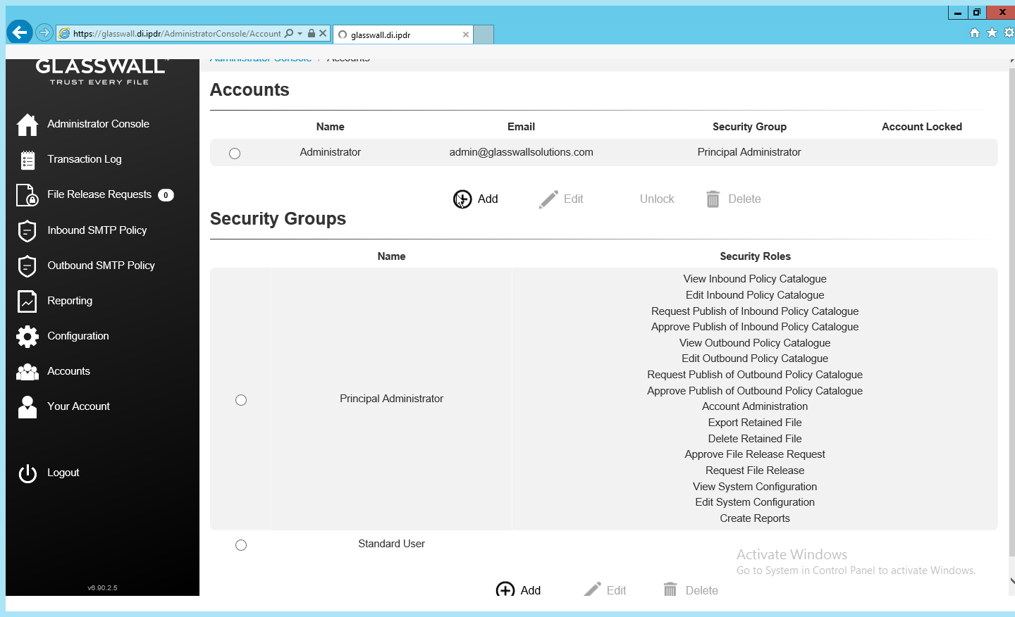
Enter the name and email address of an administrator account from the email server.
Select Principal Administrator for Security Group.
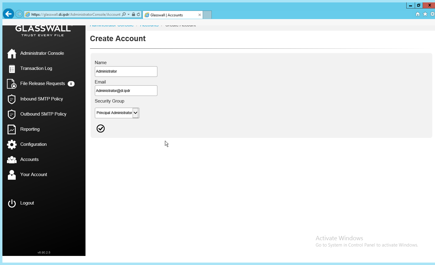
Click the checkmark button when finished.
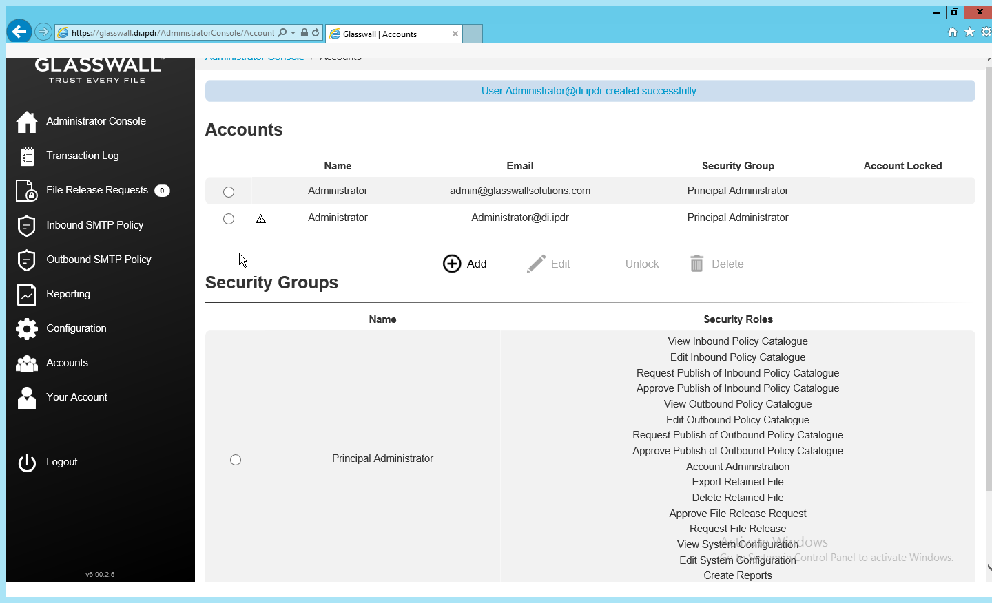
The new administrator account should be created.
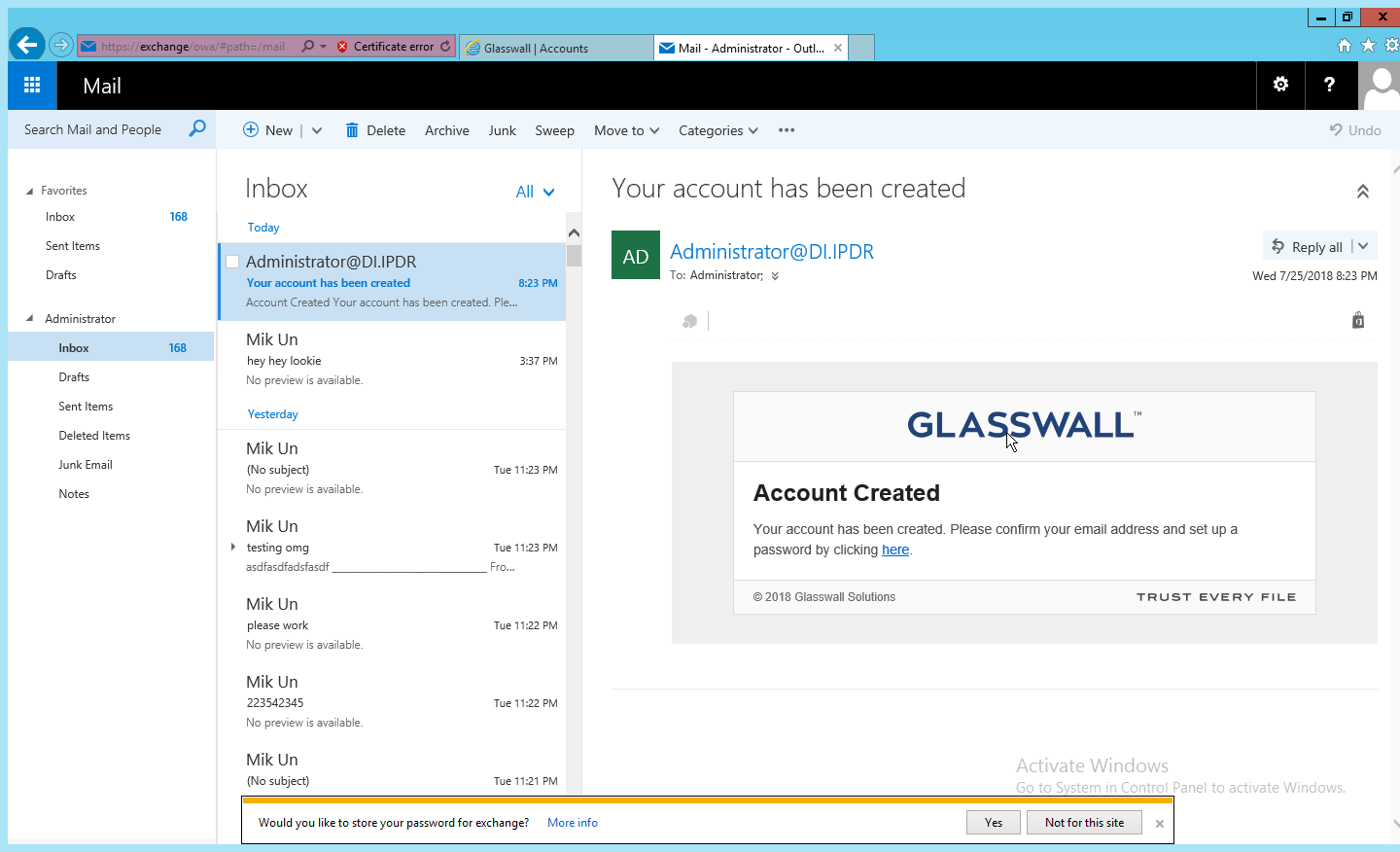
Check the email inbox of the specified email address for a confirmation email, and click the link in the email.
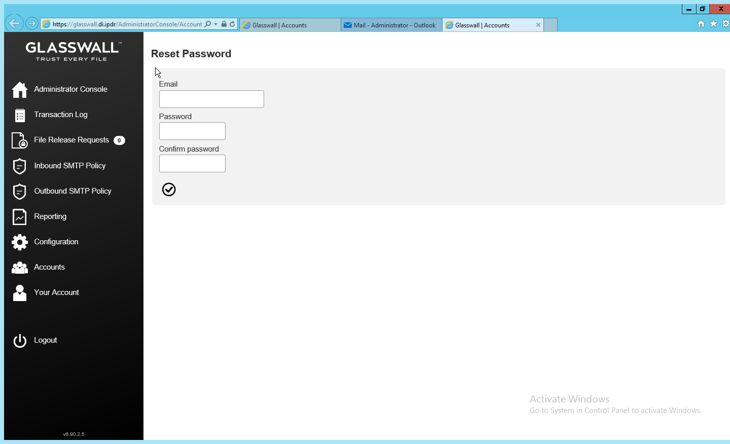
Enter the email address as well as a password for this account.
Log in as this user, and then go to Accounts.
Select the old (default) Administrator account.
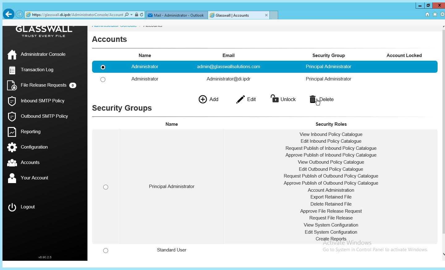
Click Delete.
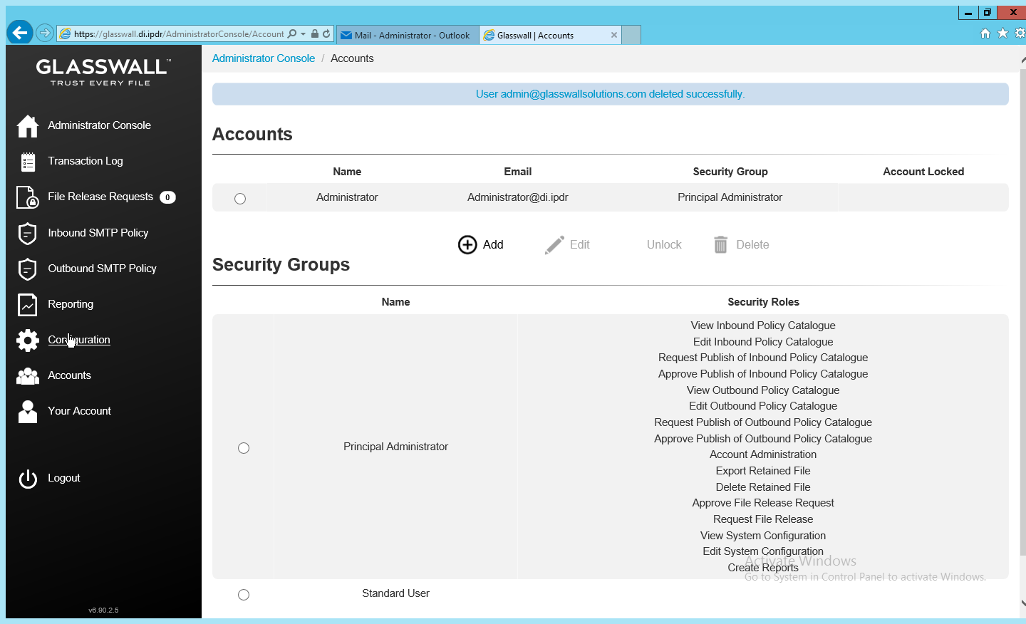
This should remove the old administrator account (note: failure to remove this can result in a significant vulnerability for this server).
2.7.3.2 Configure Notifications and Policies
Click Configuration on the left sidebar.
Click the Notifications tab.
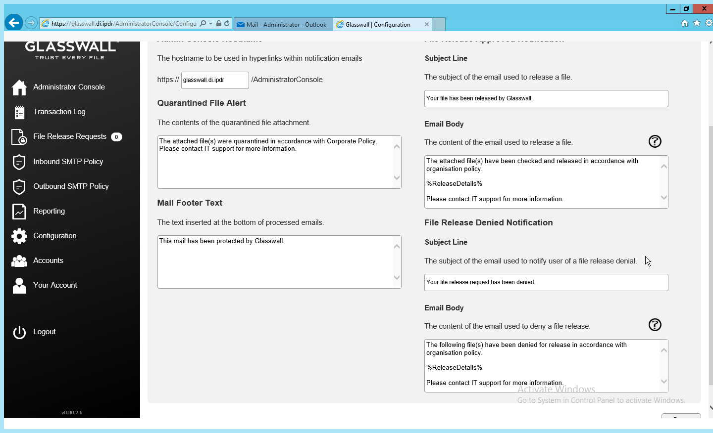
On this page, enter the web domain in the first input box (for example, glasswall.di.ipdr).
The various input boxes on this page allow you to specify the messages sent when files are quarantined, released, or prevented from being released.
Click the Inbound Agents tab.
Select Analysis and Protect for Processing Mode. (This analyzes and quarantines/reconstructs files based on policy.)
Select Active for File Preview Mode. (This provides clients with a preview of their received files if they were quarantined, so they can determine whether they should request the file be released.)
Enter the domain for Allowed Domains (for example, di.ipdr).
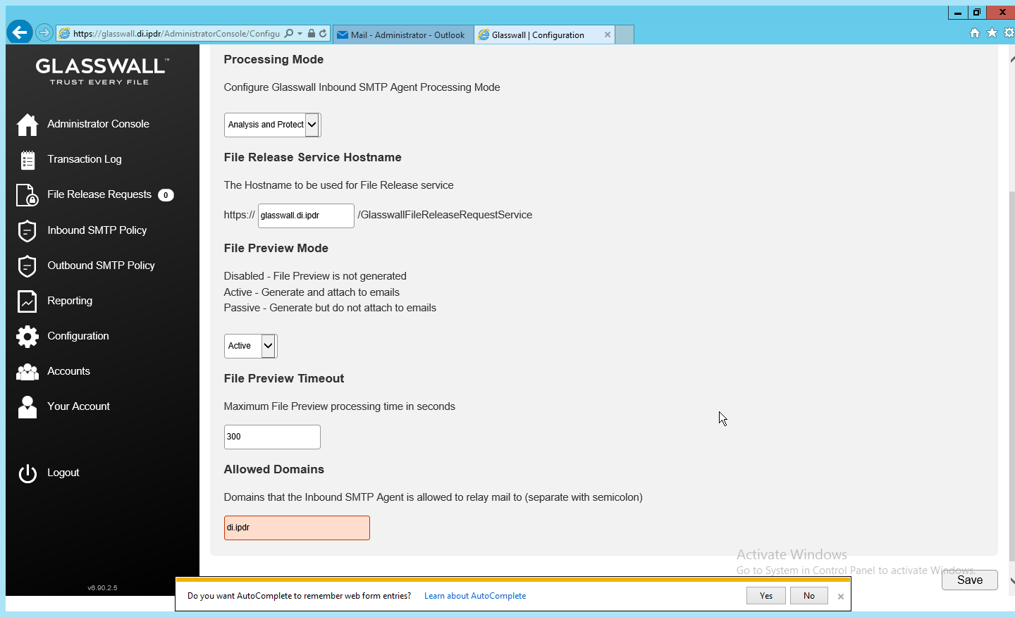
Click Save.
2.7.3.3 Configure Inbound SMTP Policy
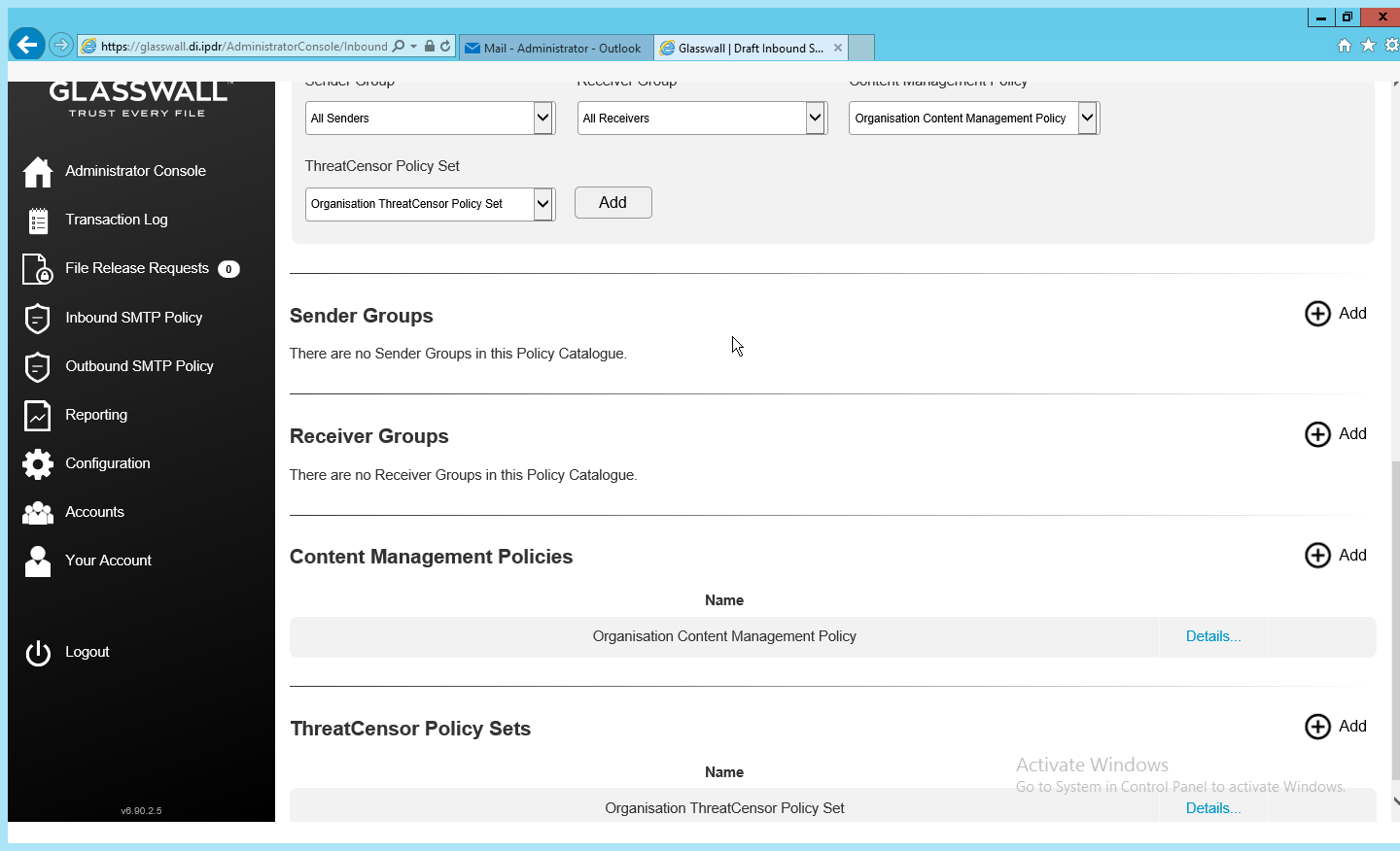
This section discusses Simple Mail Transfer Protocol (SMTP) policy under Glasswall FileTrust. There are several layers of granularity for configuring Email policy. Because policy is dependent on the organization’s needs, we will not prescribe a policy but will showcase how a policy is formed.
Policy in Glasswall FileTrust consists of Sender Groups, Receiver Groups, Content Management Policies, and ThreatCensor Policy Sets. Receiver groups allow for the specification of users who receive email. Sender groups allow for the specification of emails received from specific senders. Content Management Policies refer to the default policy on various filetypes. Lastly, ThreatCensor Policy Sets allow for the specification of policy on specific error codes; through this it is possible to place policies on encrypted email, for example, depending on the organization’s needs.
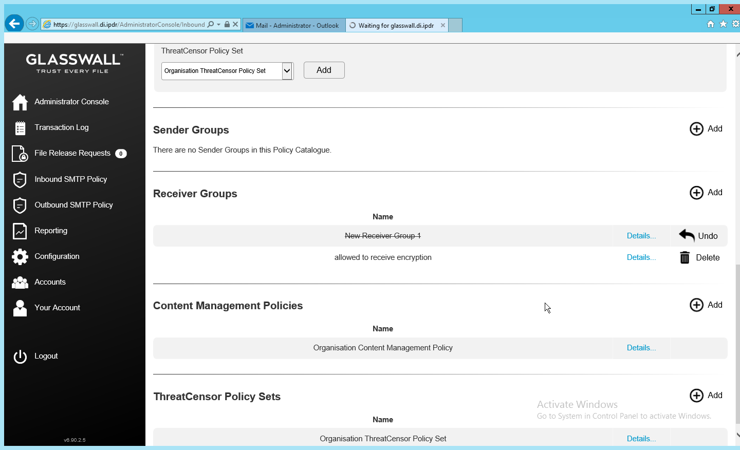
2.7.3.4 Create a Receiver Group
On the left sidebar, click Inbound SMTP Policy.
Click Draft Policy Catalogue.
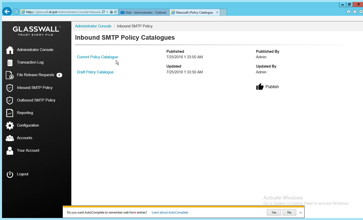
Under Receiver Groups, click Add.
Under User Defined Mailboxes, click Edit.
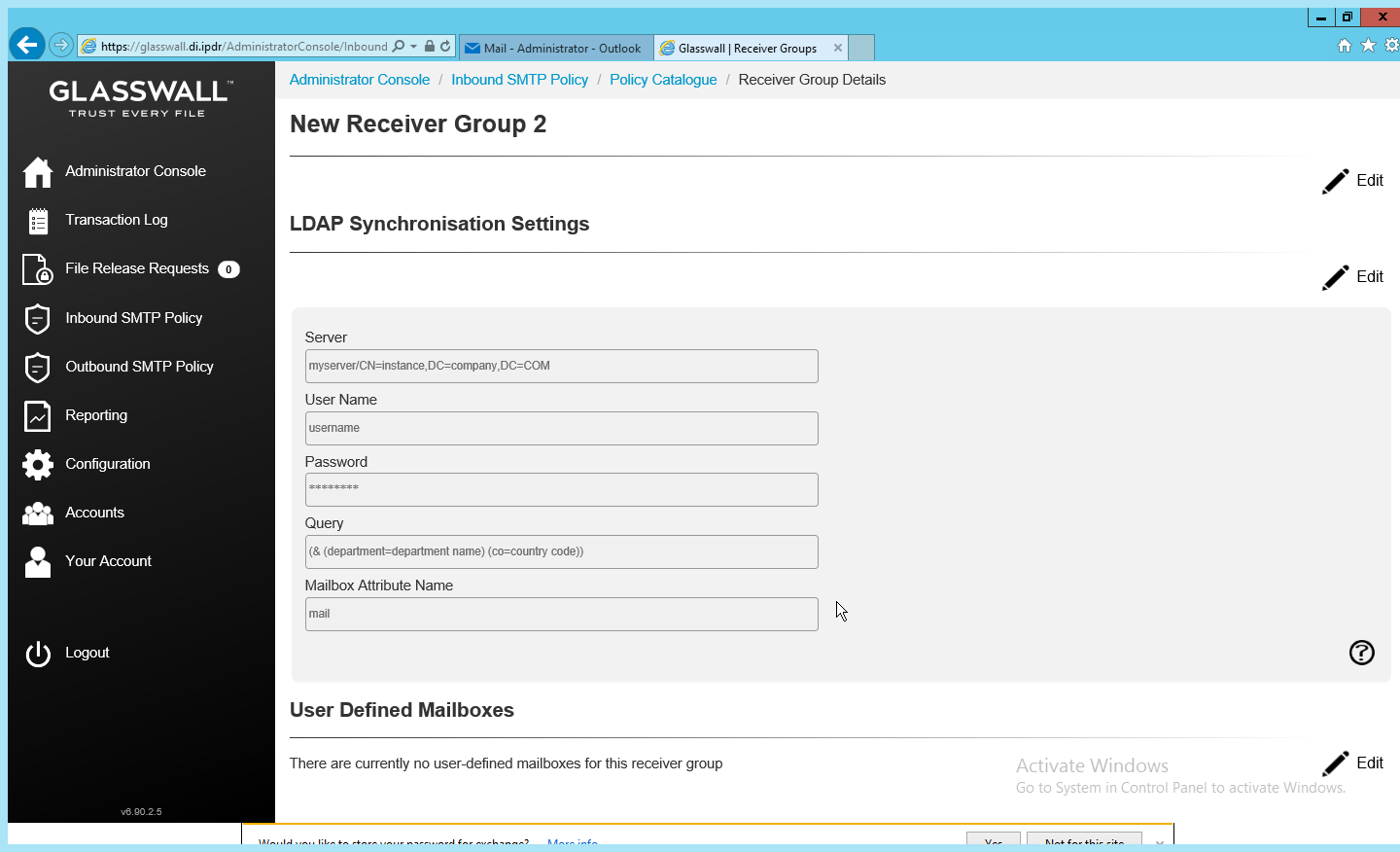
Enter the email address(es) of users who should be in this receiver group.
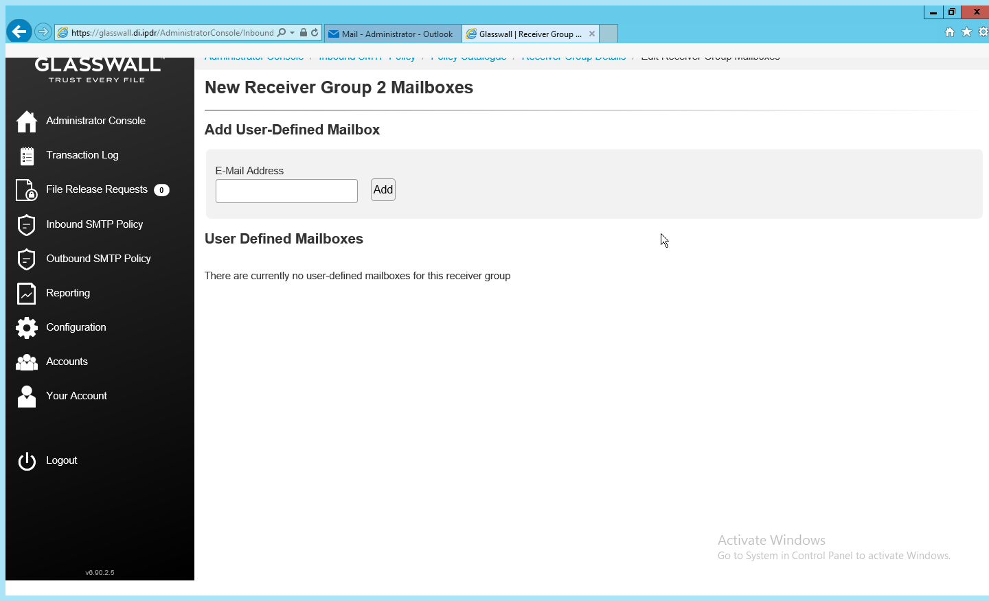
Click Add.
When finished, return to the Policy Catalogue page.
2.7.3.5 Create a ThreatCensor Policy Set
Under ThreatCensor Policy Sets, click Add.
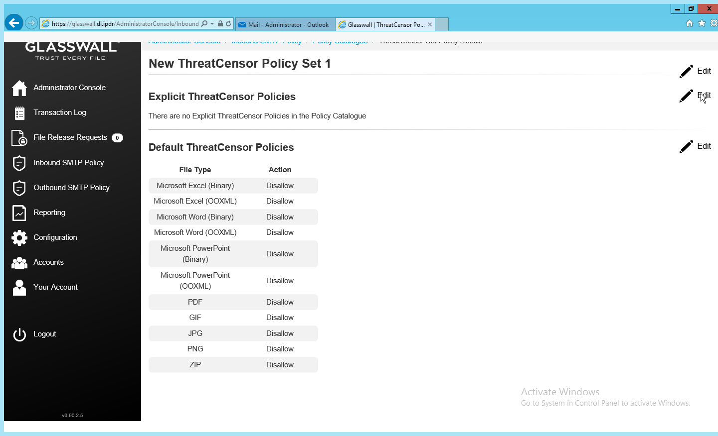
Under Explicit ThreatCensor Policies, click Edit.
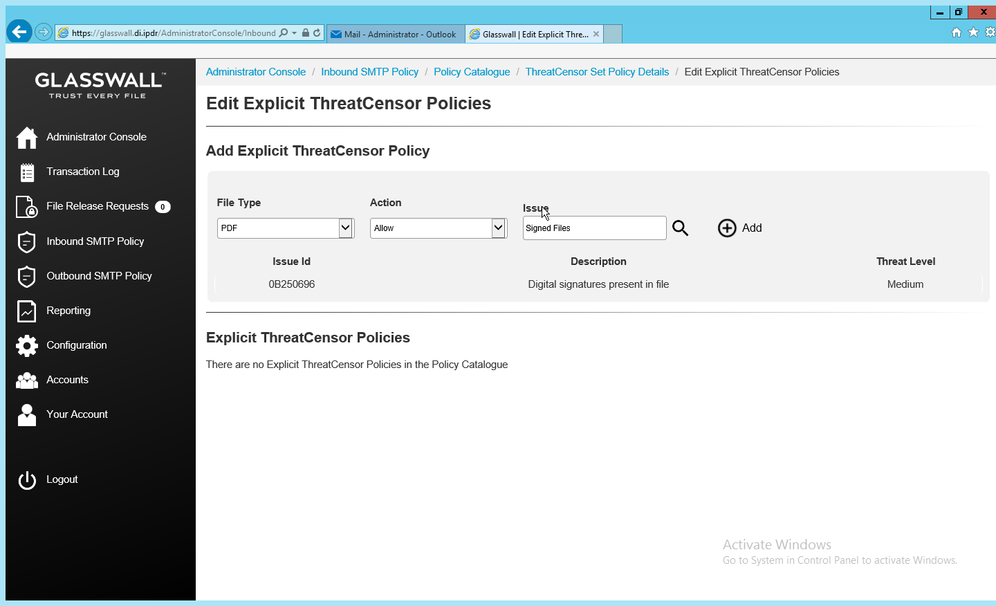
Select the File Type and Action for the rule.
Under Issue, click the magnifying glass to search for an error code.
Return to the Policy Catalogue page when finished.
2.7.3.6 Create a Processing Rule
Under Processing Rules, select the appropriate Sender Group, Receiver Group, Content Management Policy, and ThreatCensor Policy Set.
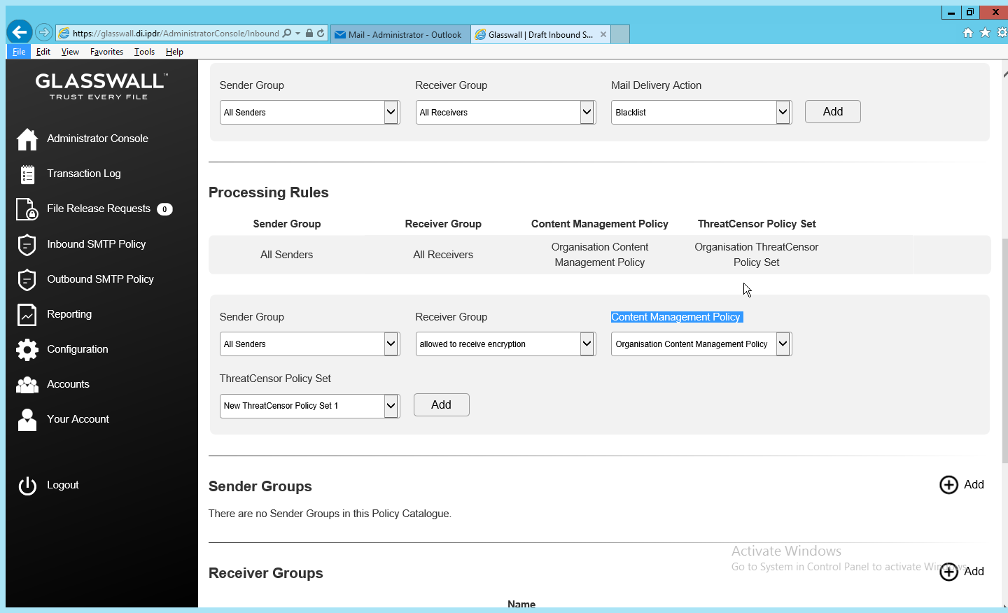
Click Add.
This allows for granular policy for email inspection, quarantine, and reconstruction.
2.7.4 Configure Intelligence Sharing
Run DataCollectorInstaller.msi.
Click Next.
Check the box next to I accept the terms in the License Agreement.
Click Next.
Select Hashed for Collection Mode (especially if your data is sensitive; this will prevent the release of any identifying information).
For Integration Service Url replace localhost with the name of the computer running the Integration Service.
Enter the username and password.
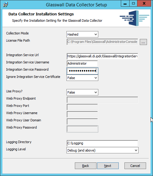
Click Next.
Click Install.

Click Finish.
2.8 Micro Focus ArcSight Enterprise Security Manager
Micro Focus ArcSight Enterprise Security Manager (ESM) is primarily a log collection/analysis tool with features for sorting, filtering, correlating, and reporting information from logs. It is adaptable to logs generated by various systems, applications, and security solutions.
This installation guide assumes a pre-configured CentOS 7 machine with ESM already installed and licensed. This section covers the installation and configuration process used to set up ArcSight agents on various machines, as well as some analysis and reporting capabilities.
Installation instructions are included for both Windows and UNIX machines, as well as for collecting from multiple machines. Furthermore, integrations with other products in the build are included in later sections.
2.8.1 Install the ArcSight Console
Run ArcSight-7.0.0.2436.1-Console-Win.exe.
Click Next.
Check the box next to I accept the License Agreement.
Click Next.
Click Next.
Click Next.
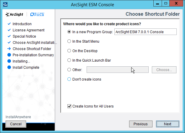
Click Next.
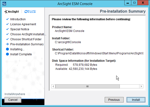
Click Install.
Select No, I do not want to transfer the settings.
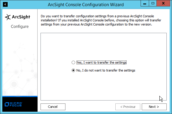
Click Next.
Select Run console in default mode. (This can be changed later according to your organization’s compliance requirements.)
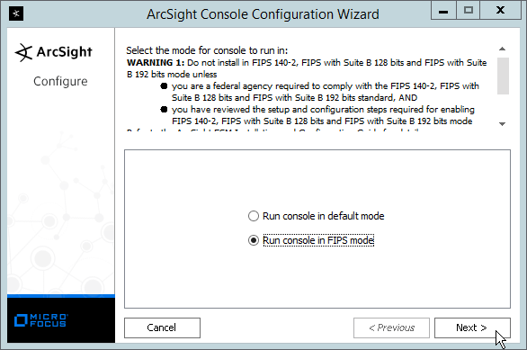
Click Next.
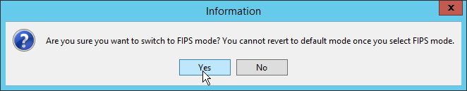
Click Yes.
Select FIPS 140-2.
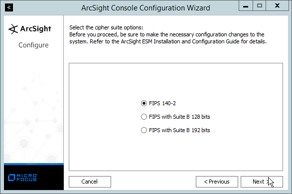
Click Next.
Enter the hostname of the ESM server for Manager Host Name.
Enter the port that ESM is running on for Manager Port (default: 8443).
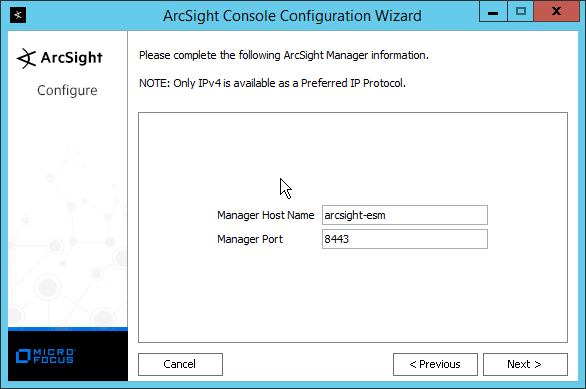
Click Next.
Select Use direct connection.
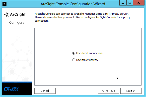
Click Next.

Click Next.
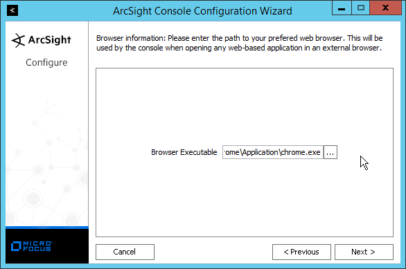
Select your preferred browser.
Click Next.
Click Next.
Click Finish.
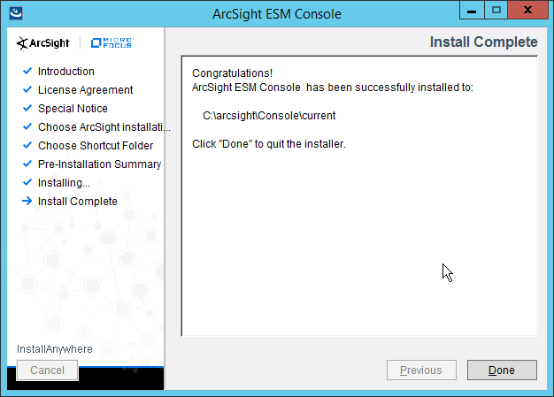
Click Done.
Run ArcSight Console from the start menu.
Enter the username and password.
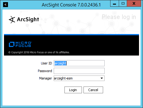
Click Login. (If you are unable to connect, ensure that the hostname of the ESM server is present in your DNS server.)
Click OK.
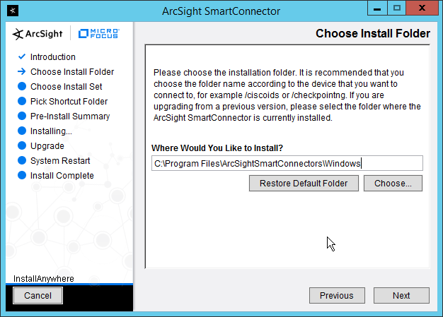
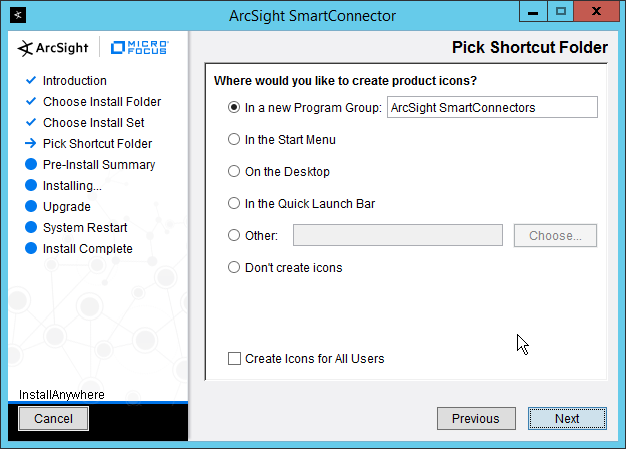
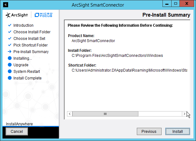
2.8.2 Install Individual ArcSight Windows Connectors
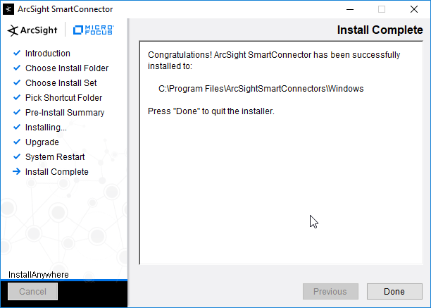
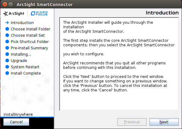
Run ArcSight-7.9.0.8084.0-Connector-Win64.exe.
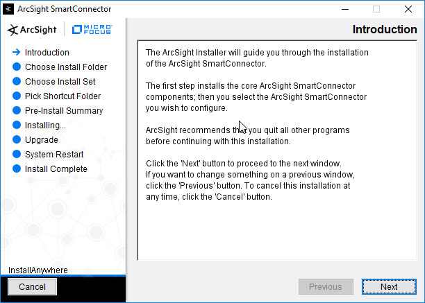
Click Next.
Enter C:\Program Files\ArcSightSmartConnectors\Windows.
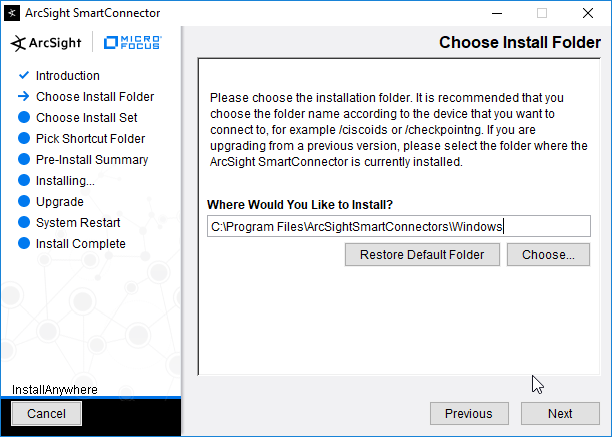
Click Next.
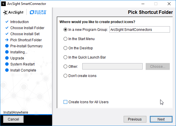
Click Next.
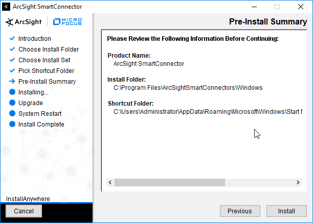
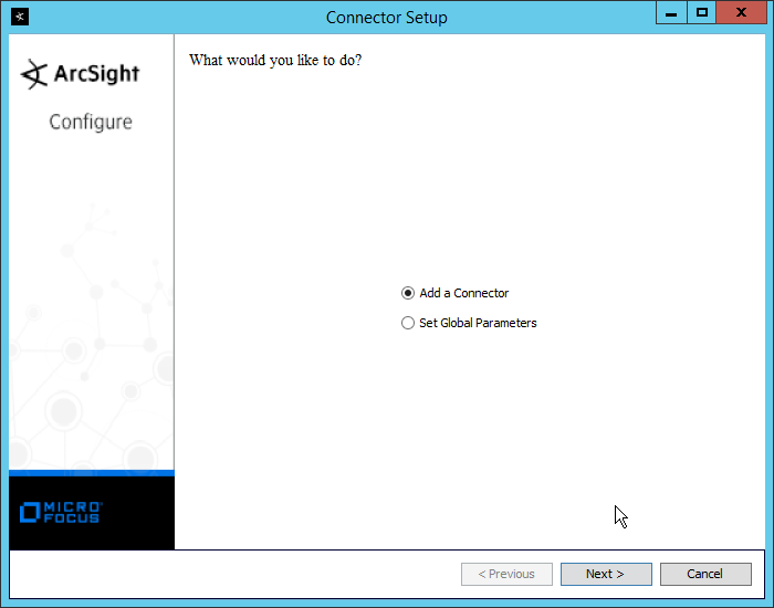
Click Install.
Select Add a Connector.
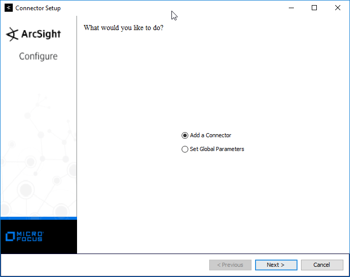
Click Next.
Select Microsoft Windows Event Log – Native.
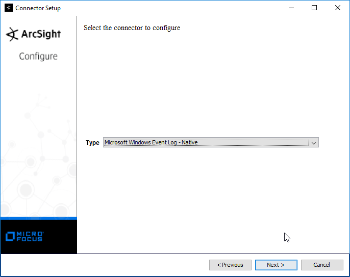
Click Next.
Click Next.

Click Next.
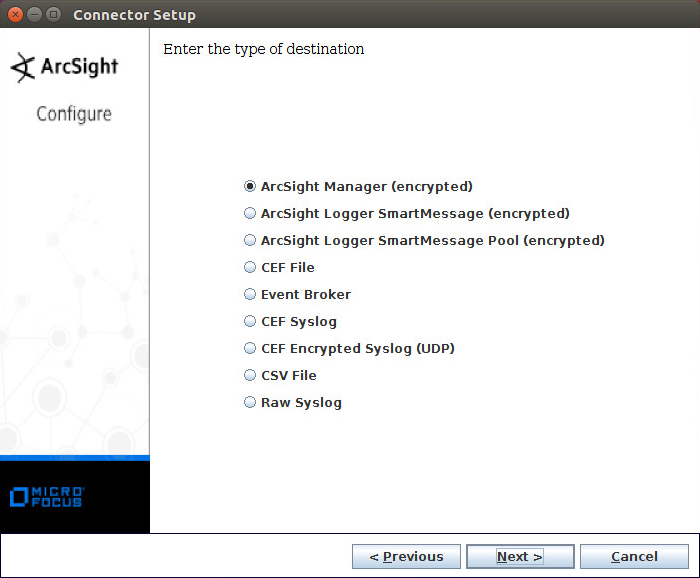
Select ArcSight Manager (encrypted).
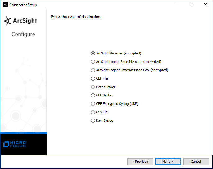
Click Next.
Enter the hostname, port, username, and password for the ArcSight ESM server.

Click Next.
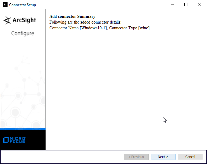
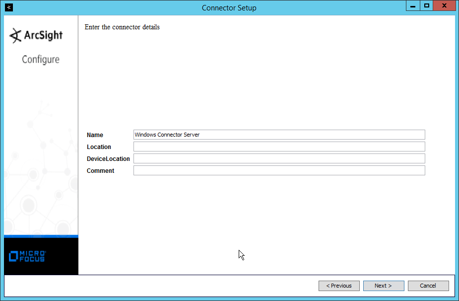
Enter identifying details about the system (only Name is required).

Click Next.
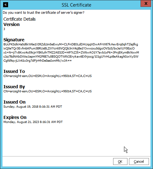
Select Import the certificate to connector from destination.
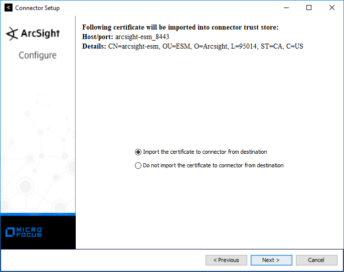
Click Next.
Click Next.
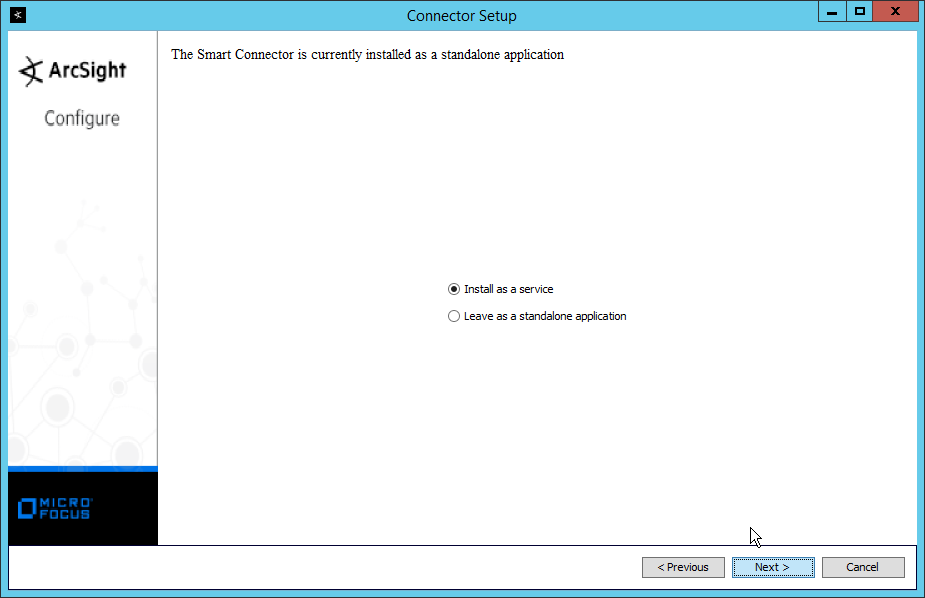
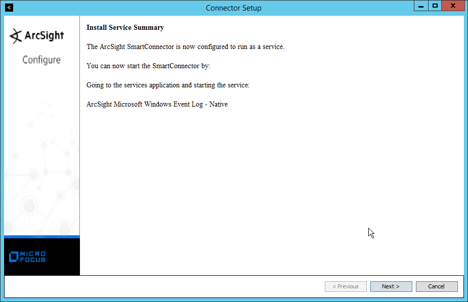
Select Install as a service.
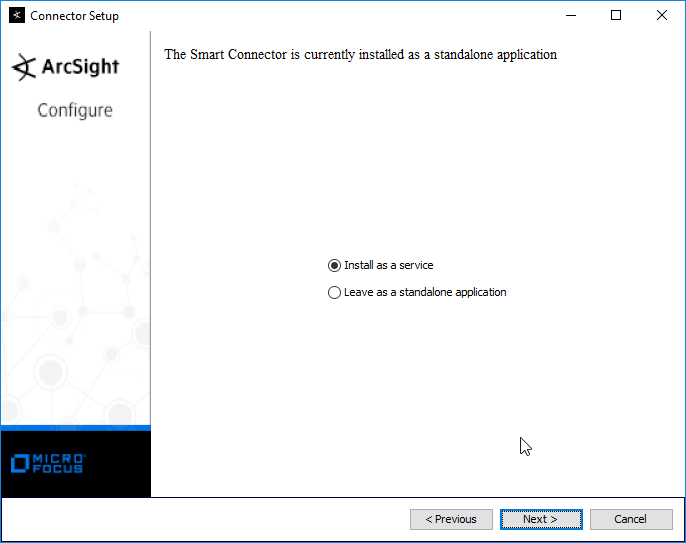
Click Next.
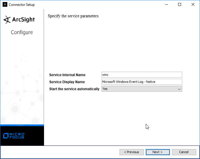
Click Next.
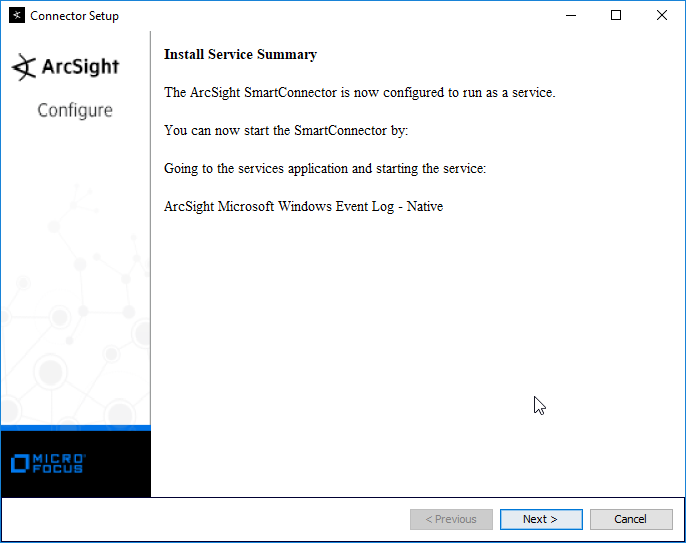
Click Next.
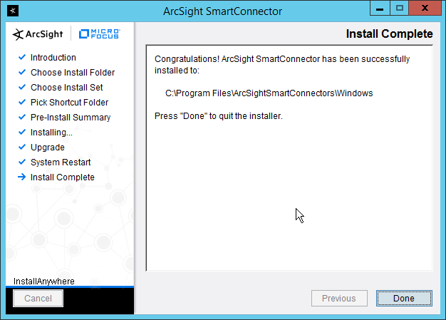
Select Exit.

Click Next.
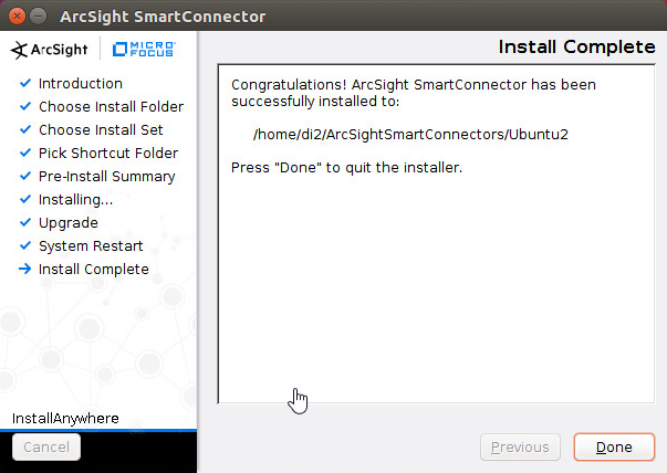
Click Done.
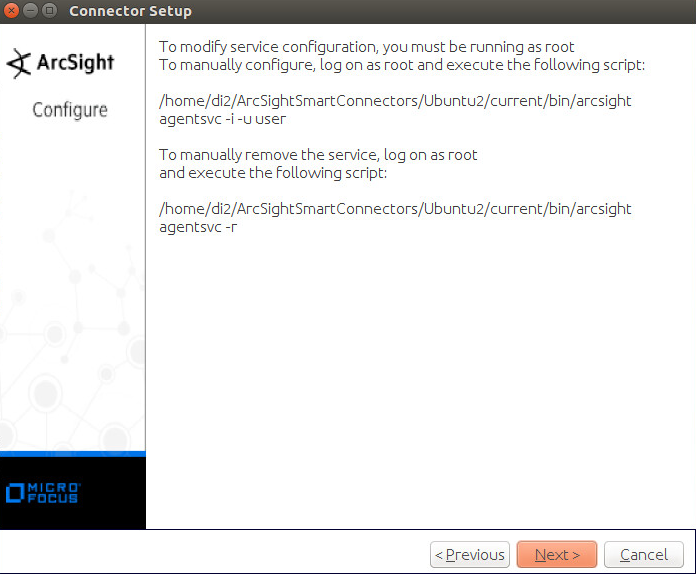
2.8.3 Install Individual ArcSight Ubuntu Connectors
From the command line, run:
> sudo ./ArcSight-7.9.0.8084.0-Connector-Linux64.binEnter the password if prompted.
Click Next.
Enter /root/ArcSightSmartConnectors/Ubuntu.
Click Next.
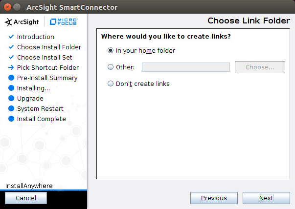
Click Next.
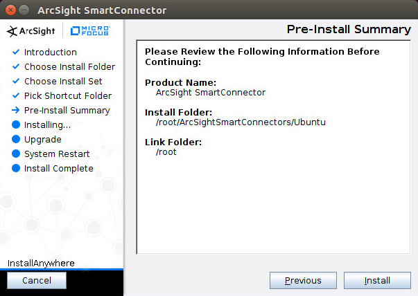
Click Install.
Select Add a Connector.
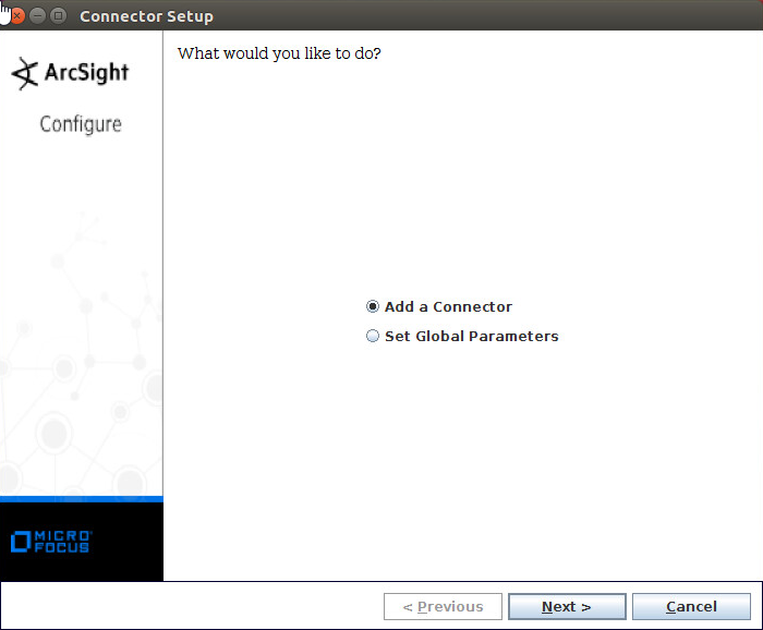
Click Next.
Select Syslog File.
Click Next.
Enter /var/log/syslog for the File Absolute Path Name.
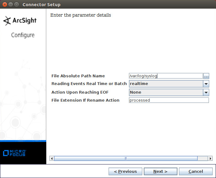
Click Next.
Select ArcSight Manager (encrypted).
Click Next.
Enter the hostname, port, username, and password for ArcSight ESM.
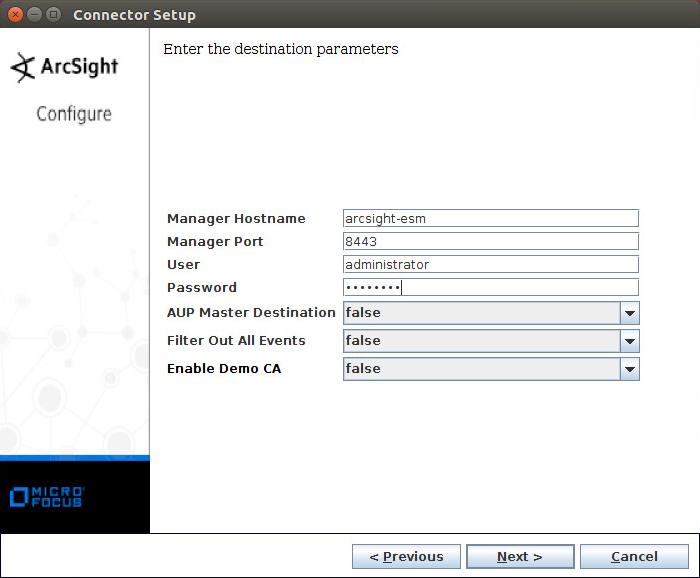
Click Next.
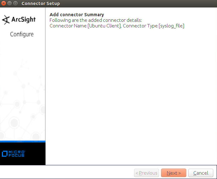
Enter identifying details about the system (only Name is required).

Click Next.
Select Import the certificate to connector from destination.
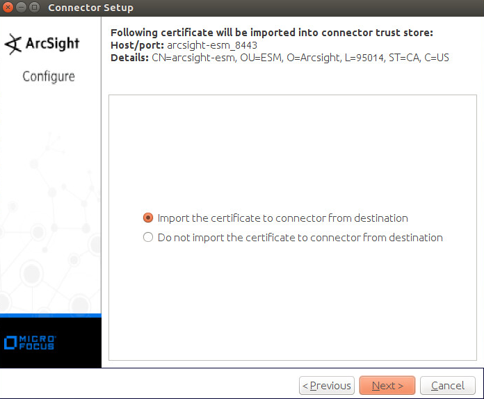
Click Next.
Click Next.
Click Next.
Select Exit.
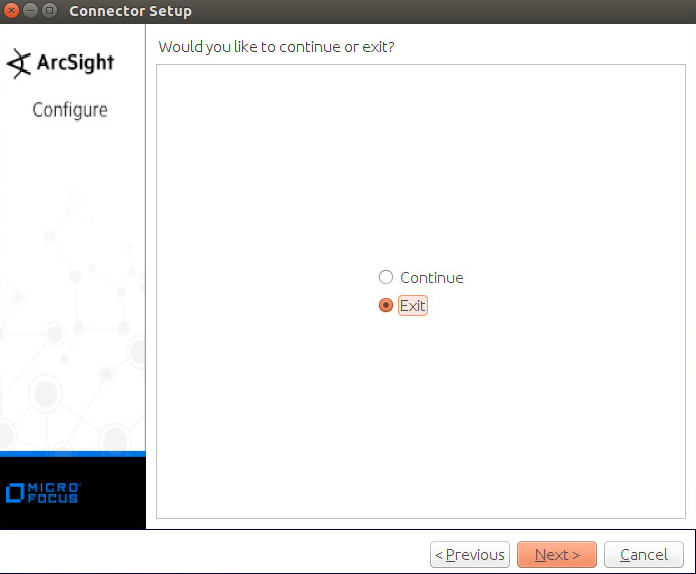
Click Next.
Click Done.
2.8.4 Install a Connector Server for ESM on Windows 2012 R2
Run ArcSight-7.9.0.8084.0-Connector-Win64.exe.

Click Next.
Enter C:\Program Files\ArcSightSmartConnectors\Windows.
Click Next.
Click Next.
Click Install.
Select Add a Connector.
Click Next.
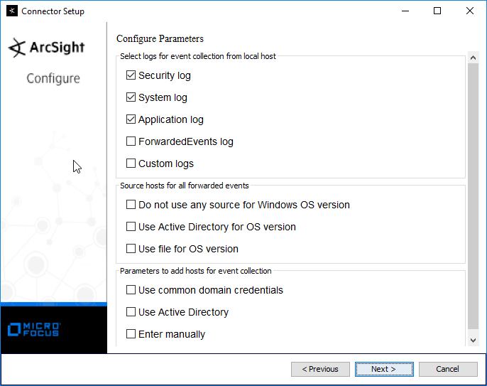
Select Microsoft Windows Event Log – Native.

Click Next.
Check the box next to Use Active Directory.
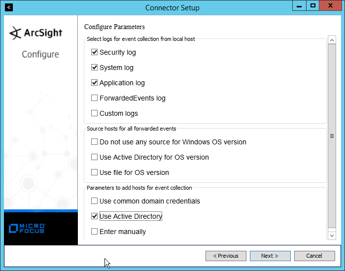
Click Next.
Enter information about your Active Directory server (it is recommended to create a new administrator account for ArcSight to use).
Set Use Active Directory host results for to Replace Hosts.
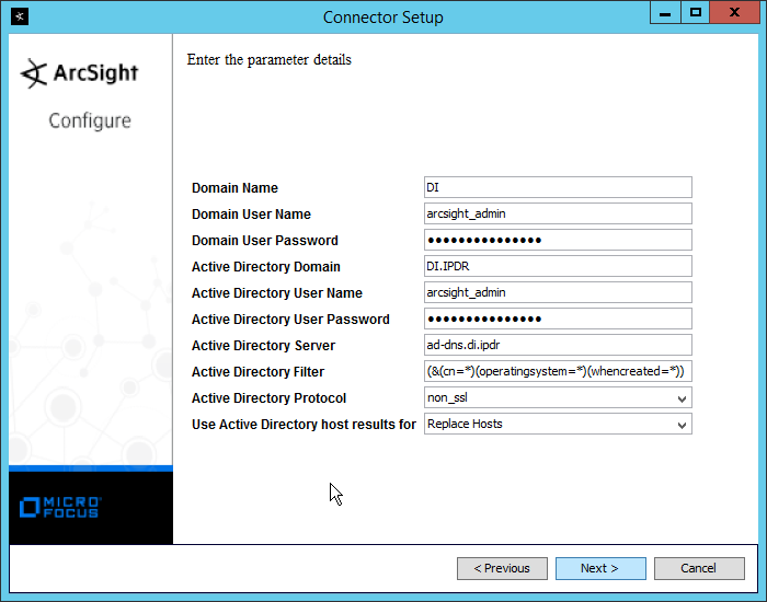
Click Next.
Check the boxes under any event types that should be forwarded to this connector, for each individual host. For example: Security, System, Application.
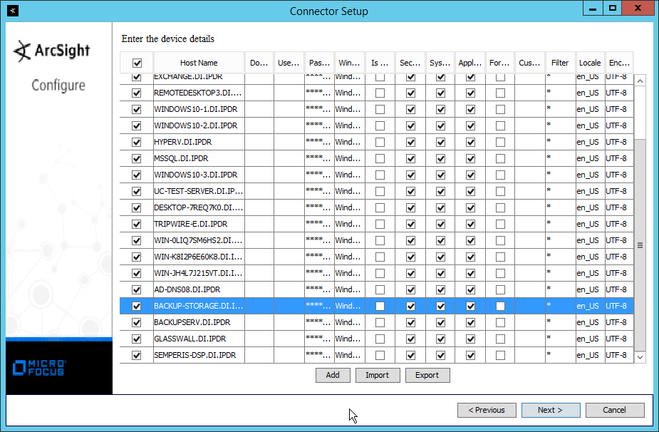
Click Next.

Click Next.
Select ArcSight Manager (encrypted).
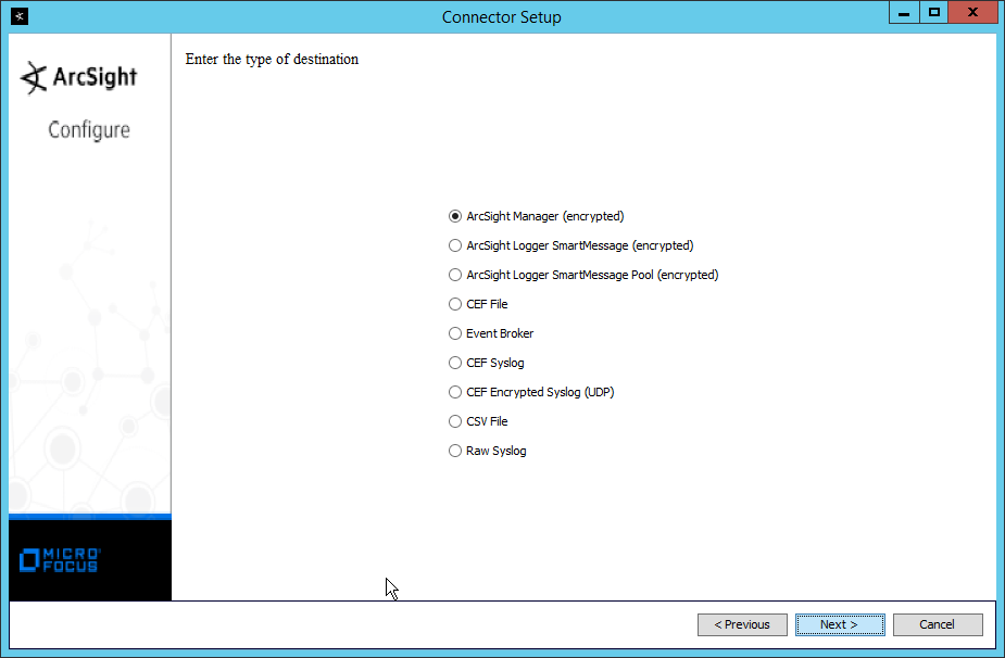
Click Next.
Enter the hostname, port, username, and password for the ArcSight ESM server.
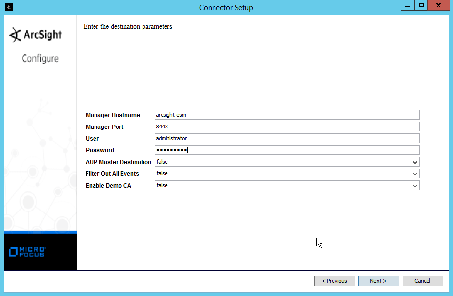
Click Next.
Enter identifying details about the system (only Name is required).
Click Next.
Select Import the certificate to connector from destination.

Click Next.

Click Next.
Select Install as a service.
Click Next.

Click Next.
Click Next.
Select Exit.

Click Next.
Click Done.
Note: Ensure that all machines selected do not block traffic from this device through their firewalls.
2.8.5 Install Pre-Configured Filters for ArcSight
2.8.5.1 Install Activate Base
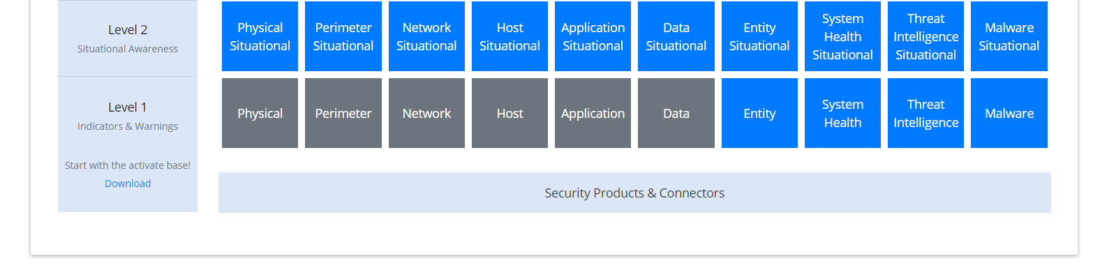
Go to the ArcSight Content Brain web app (https://arcsightcontentbrain.com/app/) and log in. This page allows you to keep track of packages to be installed—which packages should be installed is dependent on the needs of the organization, but the “activate base” is required for all products.
Click the Download link for the activate base. (Note: This package should be installed on the Arcsight Console, not on the ESM.)
Copy the contents of the zip file to ARCSIGHT_HOME. The default for this is C:\arcsight\Console\current, assuming a Windows Server.
- In PowerShell, navigate to the ARCSIGHT_HOME directory (C:\arcsight\Console\current), and run:
> .\ActivateBaseInstallAndUpdate2540.bat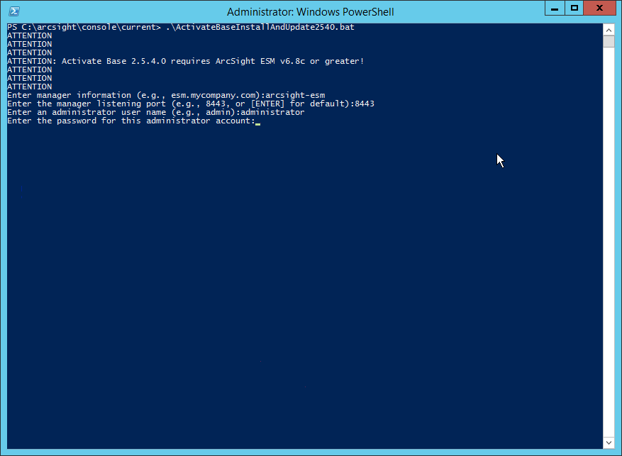
Enter the hostname of the ArcSight machine, the port (default: 8443), and the username and password used to connect to the ESM.
Delete Activate_Base_Updated_2.5.4.0.arb from the ARCSIGHT_HOME directory.
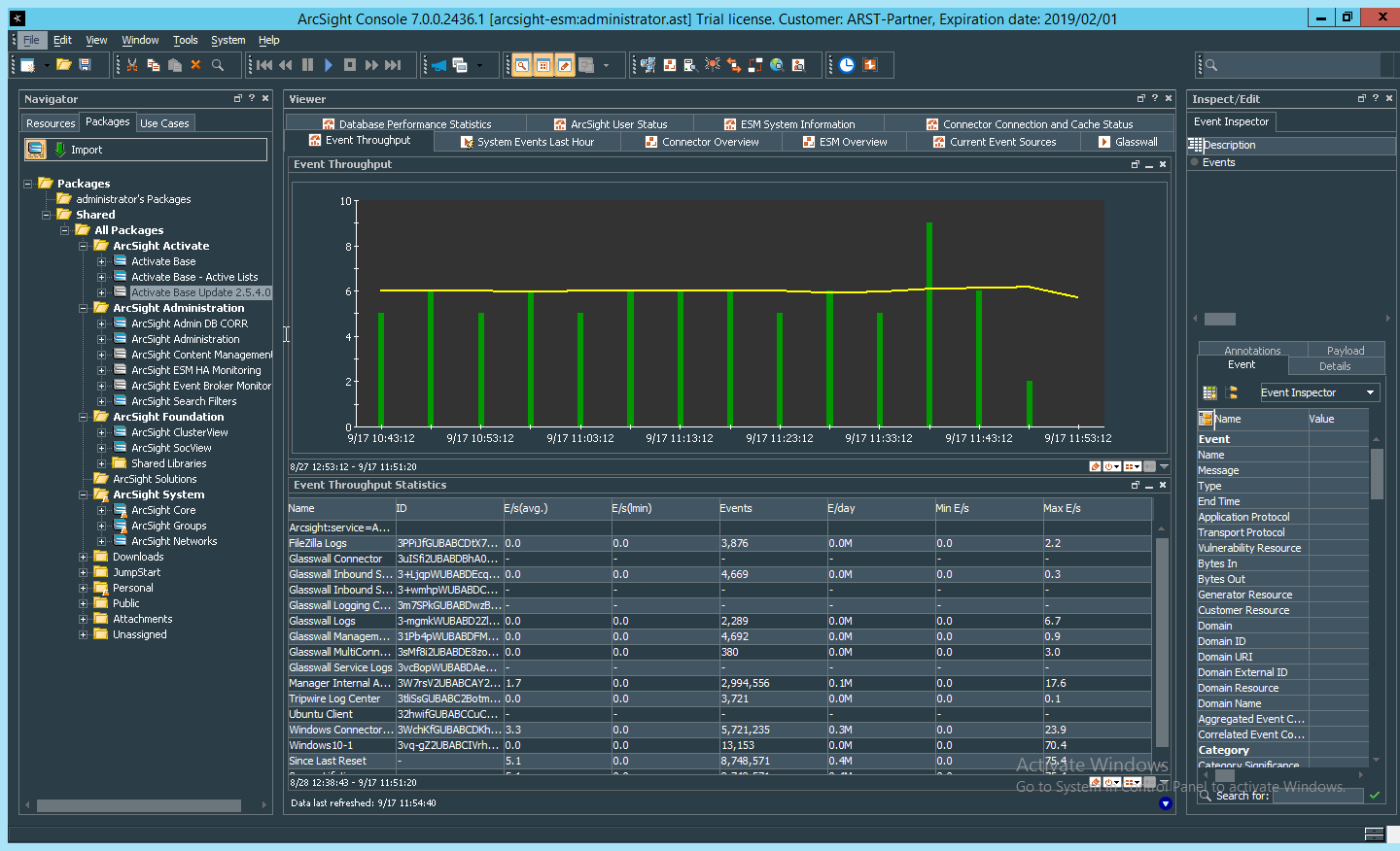
Log in to ArcSight Console.
Under Packages > Shared > All Packages > ArcSight Activate, right-click Activate Base Update 2.5.4.0, and select Delete Package.
2.8.5.2 Install Packages
Once the Activate Base is installed, packages can be installed to monitor for specific types of events. As an example, find below instructions for the Malware Monitoring package.
Navigate to the ArcSight Content Brain web app.
Select the Level 1 box labeled Malware.
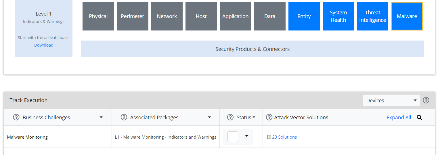
In the Track Execution section, under Associated Packages, you can see the list of packages used to address the challenge of “Malware Monitoring.” In this case, there is just one package, “L1 – Malware Monitoring – Indicators and Warnings.” Click the link to be taken to a download page for the package, and download it. (Note: This package should be installed on the Arcsight Console, not on the ESM.)
Copy the contents of the zip file to ARCSIGHT_HOME. The default for this is C:\arcsight\Console\current, assuming a Windows Server.
In PowerShell, navigate to the ARCSIGHT_HOME directory (C:\arcsight\Console\current), and run:
> .\L1-Malware_Monitoring_1.1.0.1.bat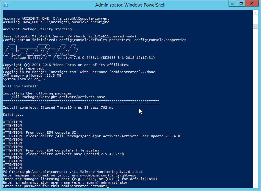
Enter the hostname of the ArcSight machine, the port (default: 8443), and the username and password used to connect to the ESM.
2.8.6 Apply Filters to a Channel
In the ArcSight Console, click File > New > Active Channel.
Enter a name for the channel.
Select a time frame.
For Filter, select one the filters that was imported from the packages you installed.
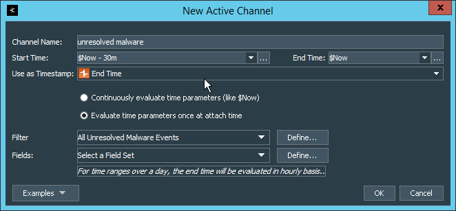
Click OK. All events that match the filter can be displayed in the newly created channel. Filters from imported packages can be found under Filters > Shared > All Filters > ArcSight Activate > Solutions.
2.8.7 Configure Email Alerts in ArcSight
2.8.7.1 Configure a New Destination
In ArcSight Console, click File > New > Destination.
Enter a name for the Destination.
For Destination Type, select Email Address.
For Email Address, enter the email that should be associated with this destination.
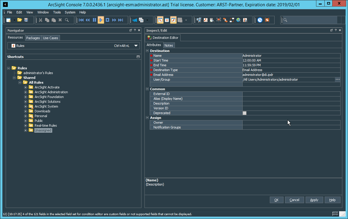
Click OK.
Select a place to save the new Destination.
Click OK.
2.8.7.2 Configure a New Rule
Click File > New > Rule > Standard Rule.
Enter a name for the rule.
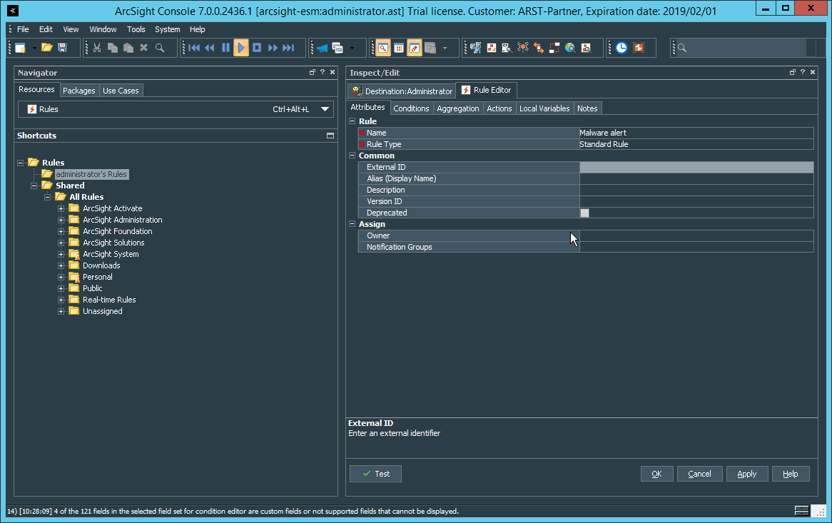
Click the Conditions tab.
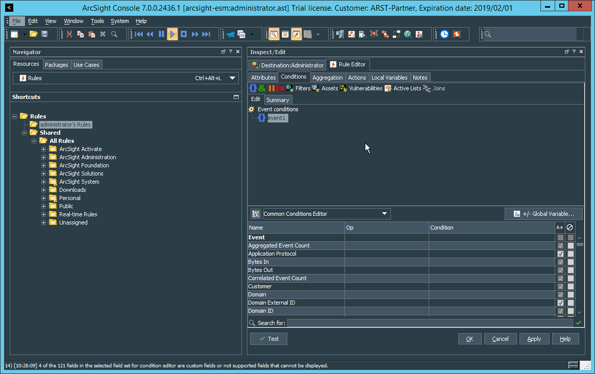
Either create a custom condition for the rule or click the Filters button to select a pre-configured Filter. (Ensure you check the box next to desired filters if you choose to select a pre-configured filter.)
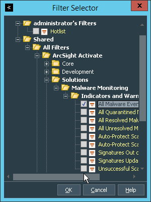
If you selected a filter, click OK.
Click the Actions tab.
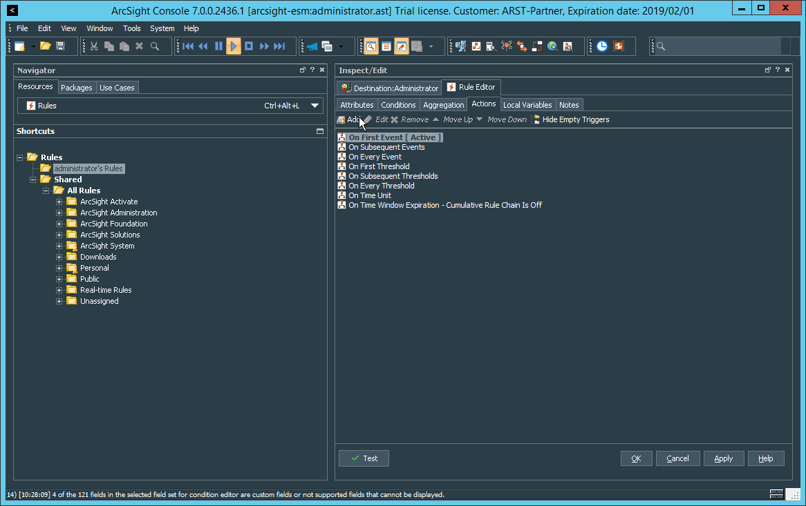
Select the trigger for the notification, and click Add > Send Notification.
Select the Destination Group in which the desired destinations reside.
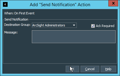
Click OK.
2.9 Tripwire Enterprise
Notes:
This installation requires MSSQL to be installed on a remote server and configured according to the instructions in the Tripwire Enterprise 8.6.2 Installation and Maintenance Guide.
2.9.1 Install Tripwire Enterprise
Ensure that you have a current version of Oracle Java. You must install both the Java Runtime Environment (JRE) and the Java Cryptography Extension (JCE).
Download and run the JRE installer.
Click Install.
Download the JCE, and extract the files.
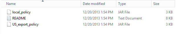
Copy the local_policy.jar and US_export_policy.jar files to /lib/security/Unlimited/ and /lib/security/Limited in the Java installation directory.
Run install-server-windows-amd64.
Select the Java runtime that was just installed.
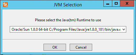
Click OK.
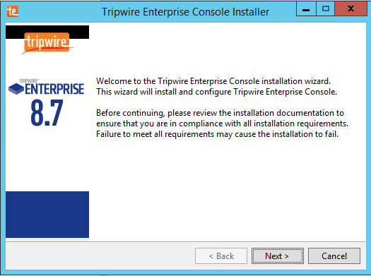
Click Next.
Select I accept the agreement.
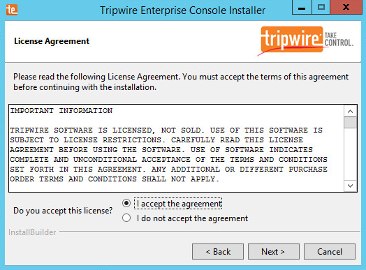
Click Next.
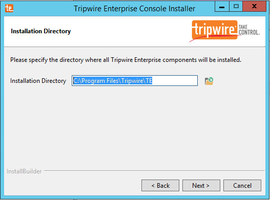
Click Next.
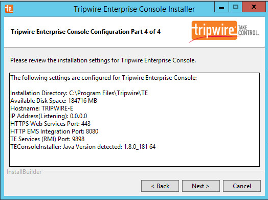
The installer should automatically detect the hostname of the system on which Tripwire Enterprise (TE) is being installed. If it does not, enter the hostname here.
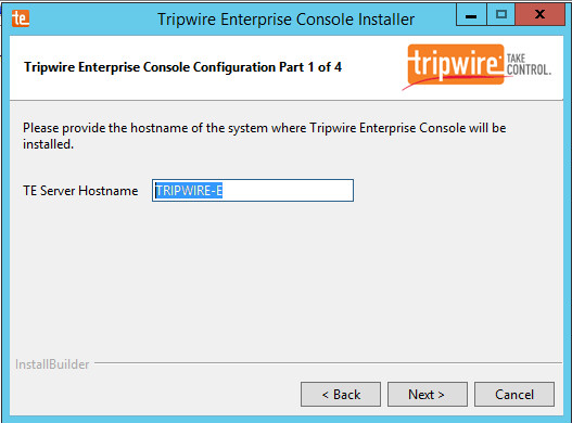
Click Next.
Enter the port numbers to use for each of the HTTPS Web Services port, HTTP EMS Integration Port, and Tripwire Enterprise RMI port. The Remote Method Invocation (RMI) port is used for inbound communication from Tripwire agents to the server, so ensure that it is allowed through the firewall.
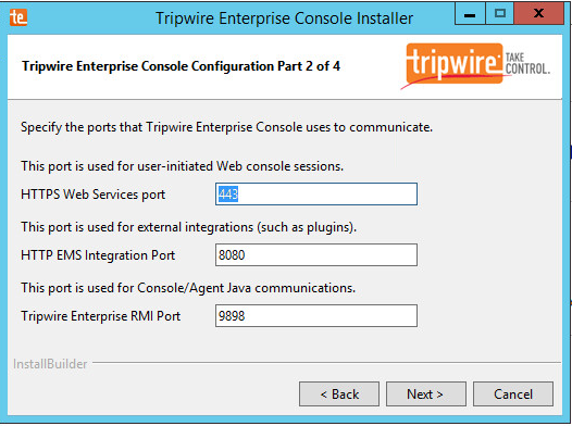
Click Next.
Enter a passphrase to use.
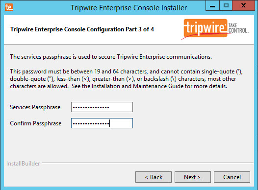
Click Next.
Click Next.
Check the box next to Install Real-time Monitoring.
Enter 1169 for Real-time Port.
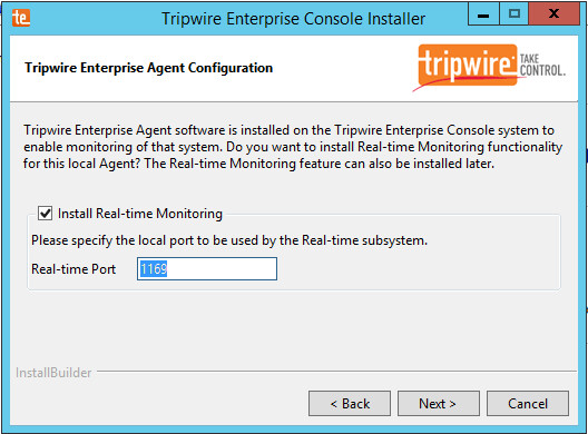
Click Next.
Click Next.
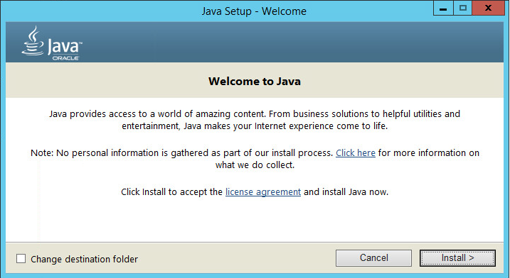
Check the box next to Open a browser after clicking Finish to continue configuring Tripwire Enterprise.
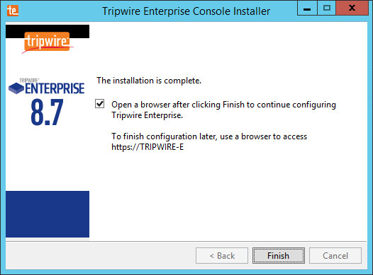
Click Finish.
Once at the web address, enter the Services passphrase chosen earlier.
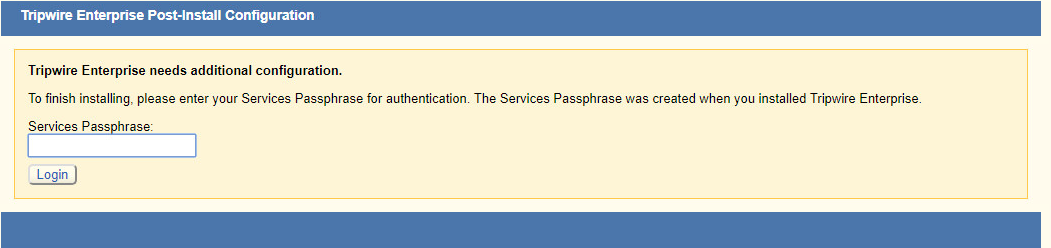
Click Login.
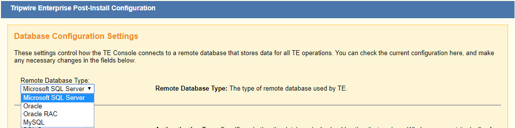
Select Microsoft SQL Server for Remote Database Type.
Select SQL Server for Authentication Type.
Enter login details for the account created during the MSSQL setup.
Enter the hostname or IP of the database server.
Enter the port on which the database is operating.
Enter the name of the database to be used for TE.
Select the appropriate setting for SSL according to your organization’s needs.
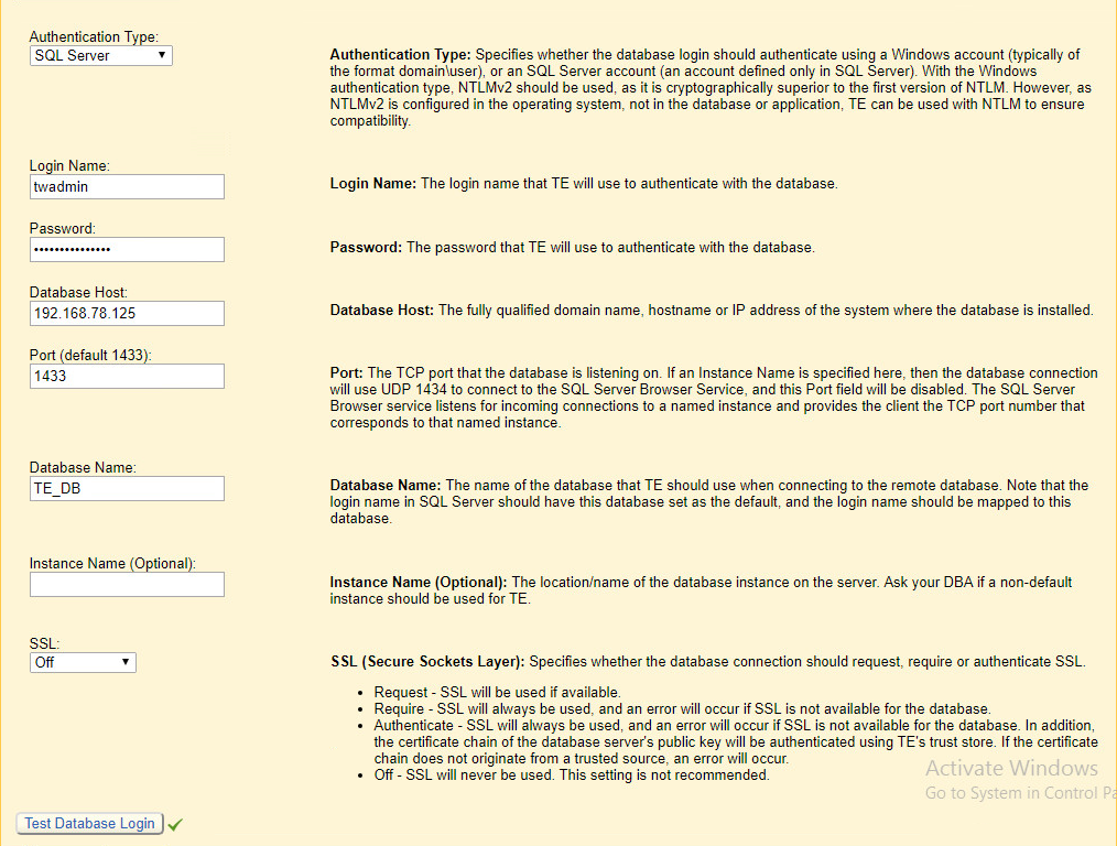
Click Test Database Login to ensure the connection is functional.
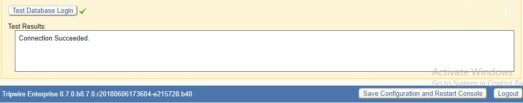
Click Save Configuration and Restart Console.
After the reboot, enter a new administrator password.
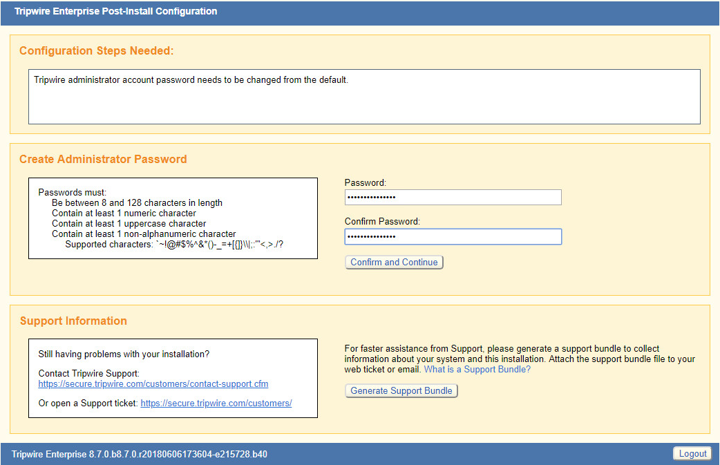
Click Confirm and Continue.
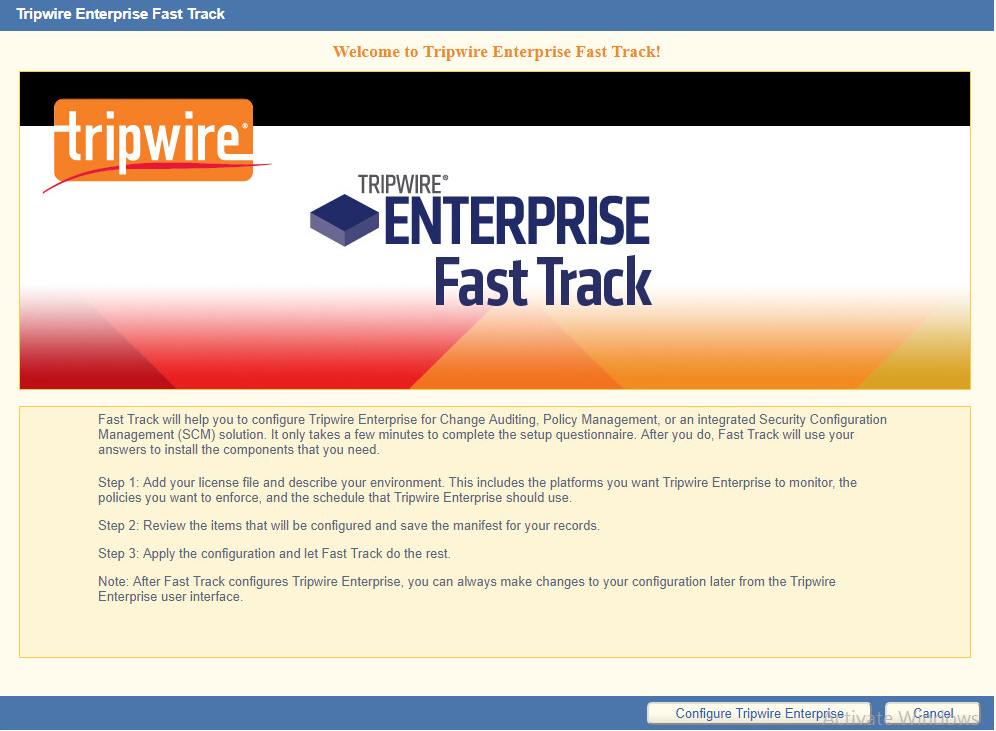
Click Configure Tripwire Enterprise.

Click Choose File, and select the TE license file, which should be a .cert file.
Check the box next to Change Auditing and Policy Management.
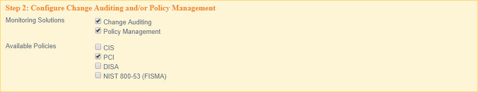
Select any available policies desired.
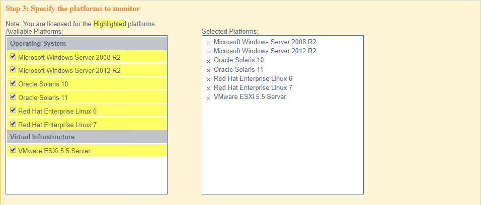
Select all the operating systems that you wish to monitor with TE.
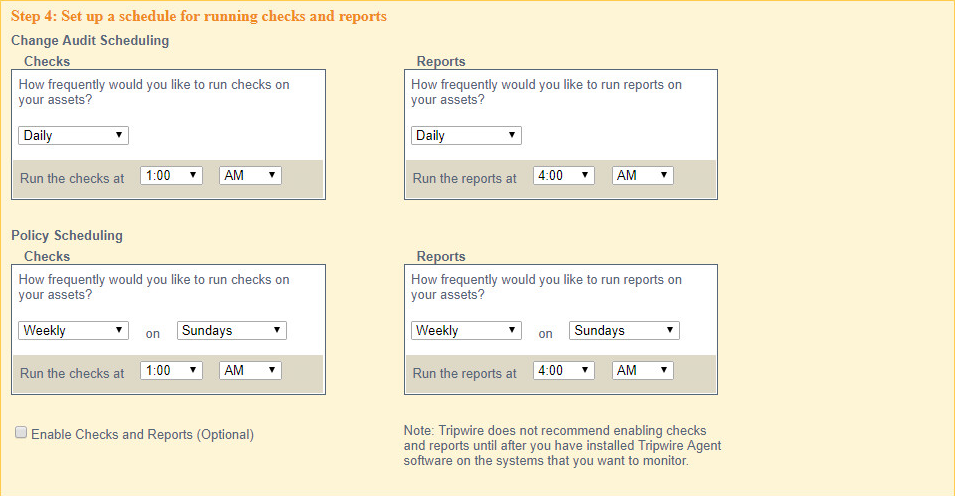
Set up a schedule for running checks and reports according to your organization’s needs. Leave the box next to Enable Checks and Reports unchecked for now.
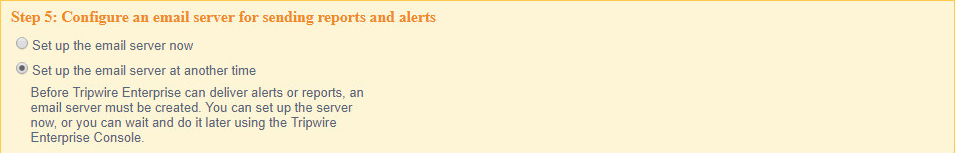
Select Set up the email server at another time.
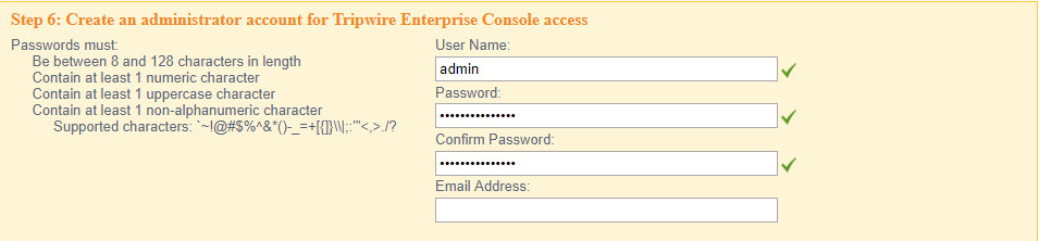
Enter a username and password for a new administrator account for TE Console.

Click Preview Configuration.
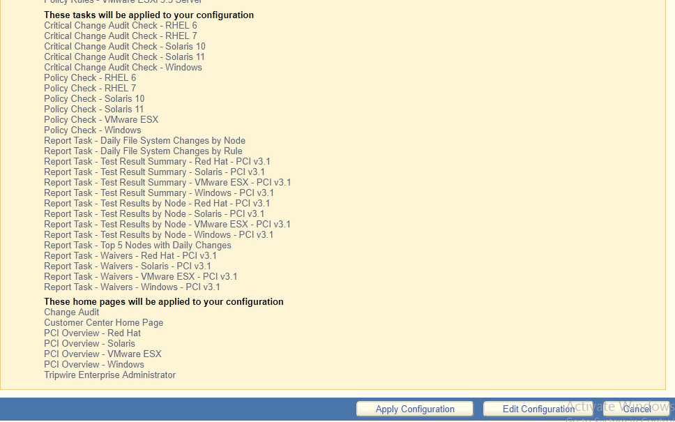
Click Apply Configuration.
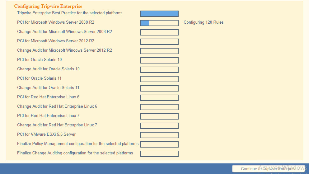
Click Continue to Tripwire Enterprise when the installation finishes.
2.9.2 Install the Axon Bridge
Ensure that TCP traffic on port 5670 is allowed through the firewall.
Navigate to the TE Console installation directory, to the /server/data/config folder. Copy bridge_sample.properties to bridge.properties.
In the bridge.properties file, find the line that says:
#tw.cap.bridge.registrationPreSharedKey=Remove the # character. After the = character, enter a password. The password has some restrictions, so ensure that it meets the requirements if the connection fails later.
Restart the TE console by running the following command from an administrator command prompt, where <te_root> is the TE installation directory:
> <te_root>/server/bin/twserver restart
2.9.3 Install the Axon Agent (Windows)
Download the Axon Agent .zip file from the Tripwire customer website (https://tripwireinc.force.com/customers), under the Product Downloads tab.
Unzip the file.
To begin the installation, double-click the .msi file in the extracted folder. Note: No installation wizard will appear; the installation happens automatically.
After the Axon Agent is installed, navigate to C:\ProgramData\Tripwire\agent\config, and copy twagent_sample.conf to twagent.conf.
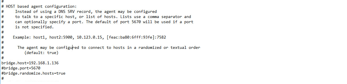
Open twagent.conf, and find the line that says
bridge.host. Remove the # character, and enter the hostname or IP address of the Axon Bridge server.In a file called registration_pre_shared_key, enter the value of the pre-shared key that was set in the Axon Bridge.
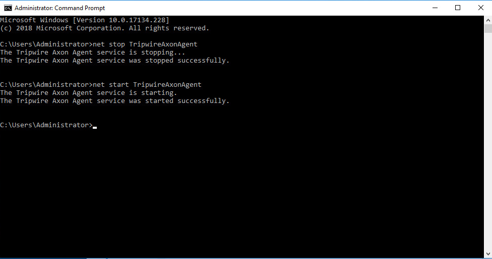
Restart the Axon Agent Service by opening a command prompt and running the following commands:
> net stop TripwireAxonAgent

> net start TripwireAxonAgent
2.9.4 Install the Axon Agent (Linux)
Download the Axon Agent .tgz file from the Tripwire customer website (https://tripwireinc.force.com/customers), under the Product Downloads tab.
To install the software, run the following commands:
Red Hat Enterprise Linux (RHEL) or CentOS:
> rpm -ivh <installer_file>Debian or Ubuntu:
> dpkg -i <installer_file>Navigate to /etc/tripwire/ and copy twagent_sample.conf to twagent.conf.
Open twagent.conf, and find the line that says
bridge.host. Remove the # character, and enter the hostname or IP address of the Axon Bridge server.In a file called registration_pre_shared_key.txt, enter the value of the pre-shared key that was set in the Axon Bridge.
Restart the Axon Agent Service by opening a command prompt and running the following commands:
RHEL or CentOS:
> /sbin/service tripwire-axon-agent stop

> /sbin/service tripwire-axon-agent start
Debian or Ubuntu:
> /usr/sbin/service tripwire-axon-agent stop

> /usr/sbin/service tripwire-axon-agent start
2.9.5 Configure Tripwire Enterprise
2.9.5.1 Terminology
Node: A monitored system, such as a file system, directory, network device, database, or virtual infrastructure component.
Element: A monitored object, which is a component or property of a node being audited by TE.
Element Version: A record of an element’s state at specific points in time. Multiple element versions create a historical archive of changes made to the element.
Rule: A rule identifies one or more elements to the TE Console.
Action: An object that initiates a response to either changes detected by TE or by failures generated from policy tests.
Task: A TE operation that runs on a scheduled or manual basis.
TE Policy: A measurement of the degree to which elements comply with a policy.
Policy Test: A determination of whether elements comply with the requirements of a policy.
Baseline: The act of creating an element that reflects the current state of a monitored object (also called the current baseline. When a node’s baseline is promoted, TE saves the former baseline as a historic baseline.
Version Check: A check on monitored objects/elements. It is a comparison of the current state of the element against its already recorded baseline for changes.
2.9.5.2 Tags
In TE, tags can be used to label and target specific nodes. Tags are not required but allow for targeting nodes more granularly than by the operating system. This section will describe how to create and assign tags.
Navigate to the TE Console in your browser.
Click Asset View.
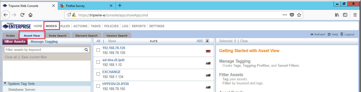
Click the Manage Tagging tab.
Enter the name of a tag set or use one of the four existing ones (Location, Owner, Platform Family, Primary Function). Click Add if adding your own tag set.
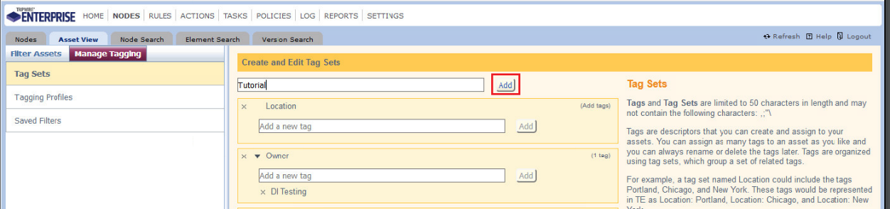
Under the tag set you wish to add a tag to, enter the name of the tag.
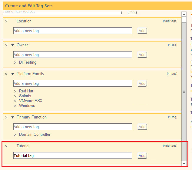
Click Add.
Navigate to Nodes > Asset View > Filter Assets.
Check the boxes next to the nodes to which you wish to add this tag.
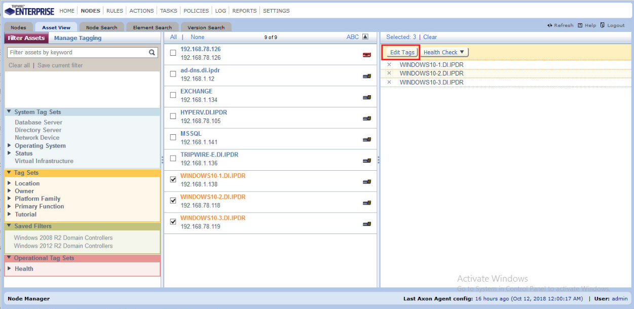
Click Edit Tags.
Check the boxes next to any tags you wish to add to these nodes.
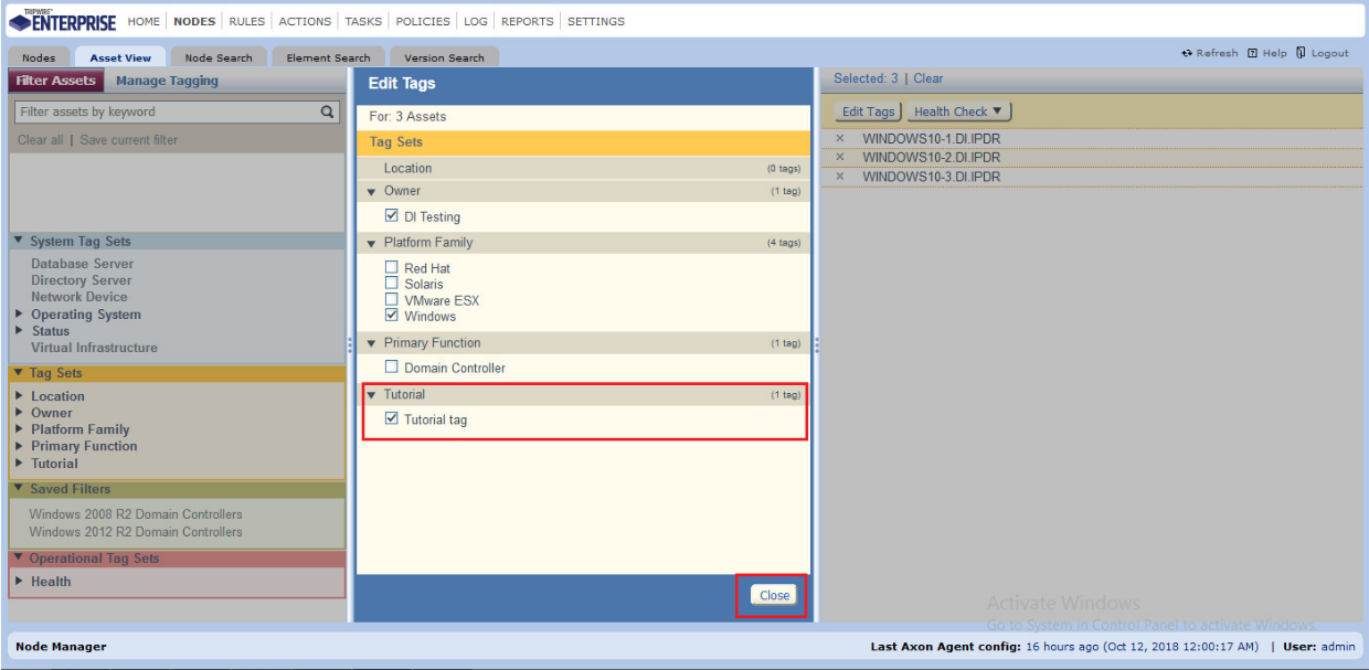
Click Close.
2.9.5.3 Rules
This section will describe how to create a rule.
Click Rules.

Select or create a rule group in which to put the new rule.
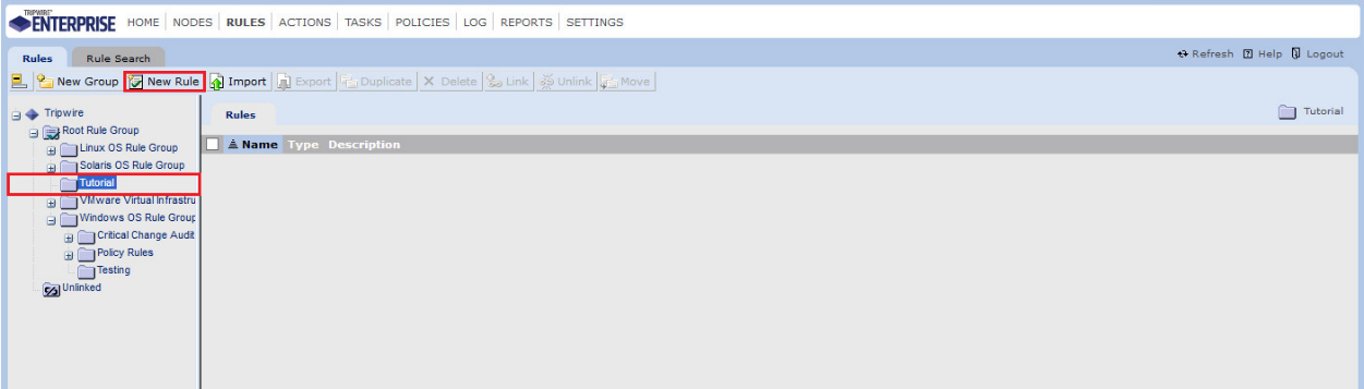
Click New Rule.
Select the type of rule. For monitoring Windows filesystems, we choose Windows File System Rule.
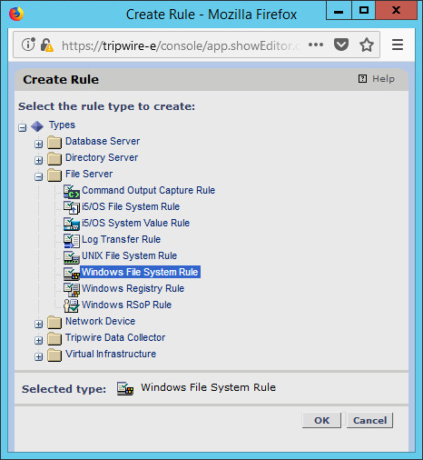
Click OK.
Enter a name and description for the rule.
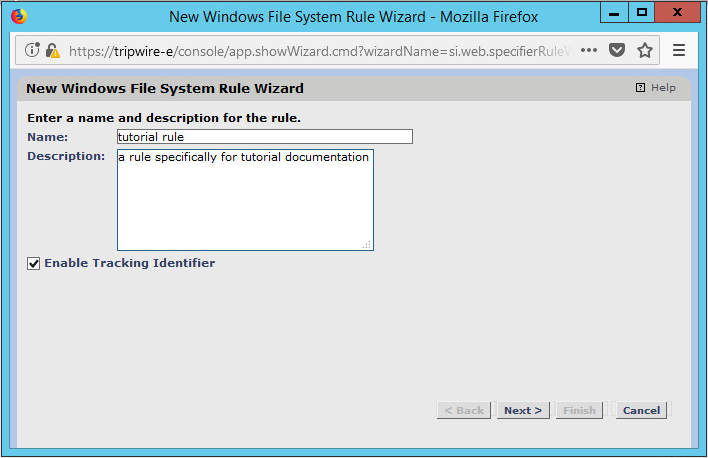
Click Next.
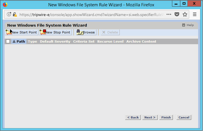
Click New Start Point.
For Path, enter a directory that represents the scope of the scan. It can be limited to the documents folder or be wide enough to encompass all the files on a system. Note that the latter will take much longer to scan.
Check the box next to Recurse directory if you also wish to scan all subfolders.
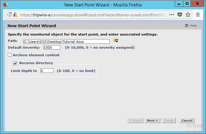
Click Next.
Select Windows Content and Permissions.
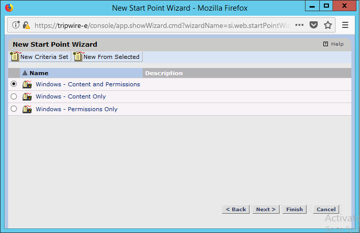
Click Finish.
Click New Stop Point.
Enter the path of any folders or files that should not be included in the scan, and indicate whether they should end the recursion.
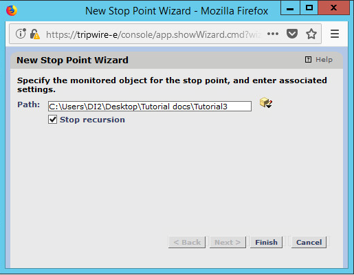
Click Finish.
Click Next.
Click Next.
Click Finish.
2.9.5.4 Tasks
This section will describe how to create a task.
Click Tasks.

Select a folder for a new task or create one.
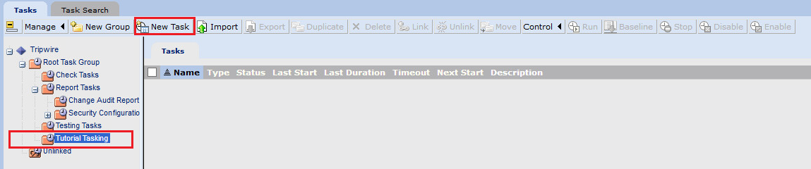
Click New Task.
Select Baseline Rule Task or Check Rule Task (Note: Both are needed: baseline creates the initial state of the monitored object, and check updates the state and reports any changes).
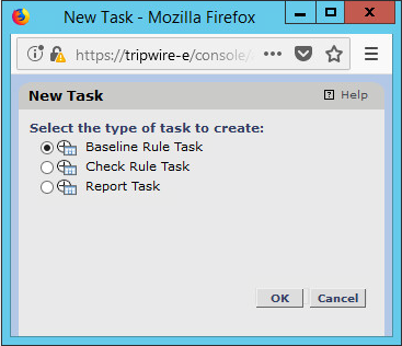
Click OK.
Enter a name and description for the task.
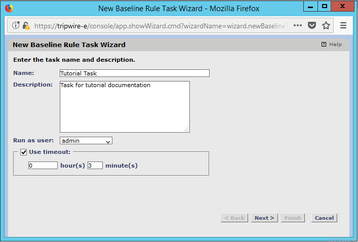
Click Next.
Select whether you want all baselines to be updated or to only create new baselines.
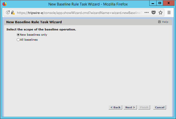
Click Next.
Select the systems to be included in the task. You can use tags or select by operating system (or other defaults).
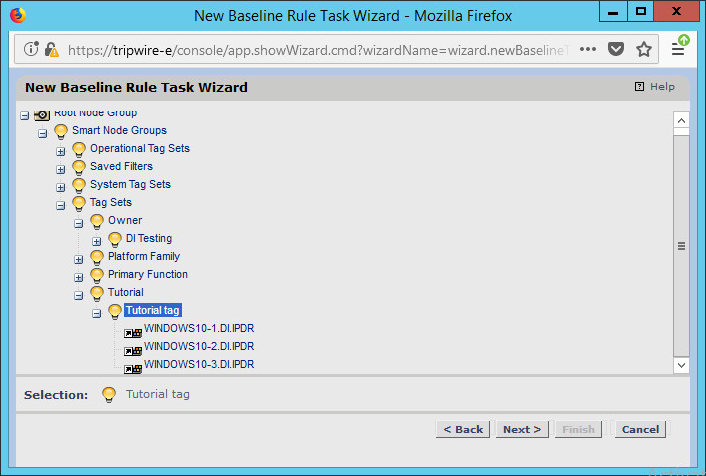
Click Next.
Select the rule created earlier.
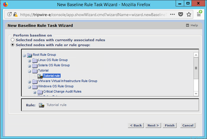
Click Next.
Set the schedule of this task according to your organization’s needs.
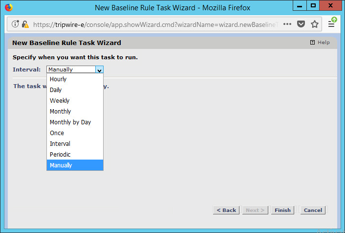
Click Finish.
2.10 Tripwire Log Center
2.10.1 Install Tripwire Log Center Manager
See the Tripwire Log Center 7.3.1 Installation Guide that should accompany the installation media for instructions on how to install Tripwire Log Center. Use the Tripwire Log Center Manager installer.
Notes:
It is recommended that you install Tripwire Log Center on a separate system from Tripwire Enterprise.
You will need to install JRE8 and the Crypto library. Instructions are also in the Tripwire Log Center 7.3.1 Installation Guide.
.NET Framework 3.5 is required for this installation; install this from the Server Manager.
You may need to unblock port 9898 on your firewall for the TE agents.
Do not install PostgreSQL if you wish to use a database on another system; this guide will use a local PostgreSQL database, however.
When it finishes installing, there should be a configuration wizard (see below for configuration steps).
2.10.2 Configure Tripwire Log Center Manager
The configuration wizard should start after the installation is complete.
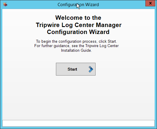
Click Start.
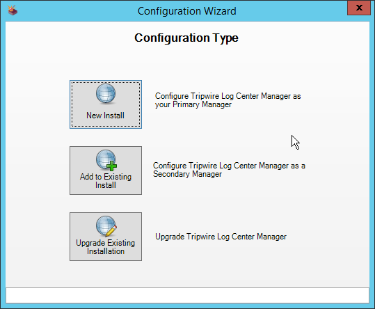
Click New Install.
Enter the registration details for your Tripwire Log Center license.
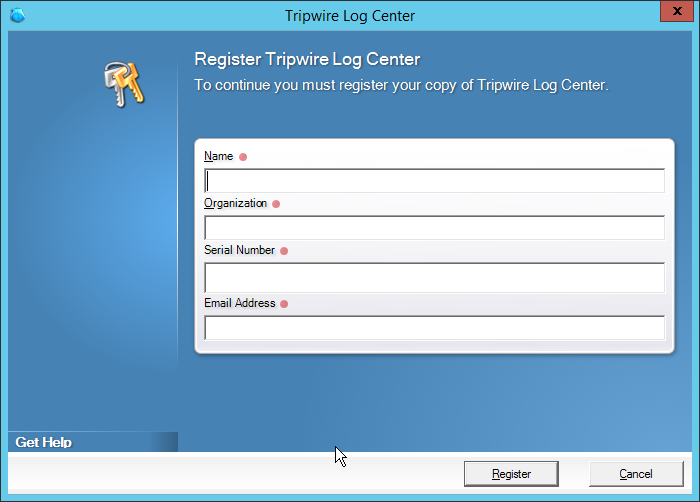
Click Register.
Enter details about the database that Tripwire Log Center should use.
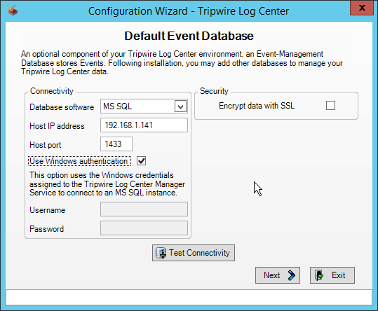
Click Next.
Select a directory to store log messages in, such as C:\Program Files\Tripwire\Tripwire Log Center Manager\Logs\AUDIT.
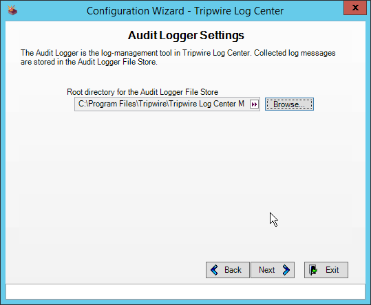
Click Next.
Enter a password and an email.
Change the IP to a hostname, if preferred.
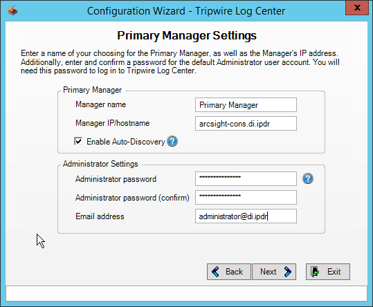
Click Next.
Click Next.
Select any log sources that you expect to collect with Tripwire Log Center. Examples: Tripwire Enterprise, Microsoft Windows 10, Tripwire IP360 VnE, Linux Debian, Ubuntu Linux, Microsoft Exchange, Microsoft SQL Server.
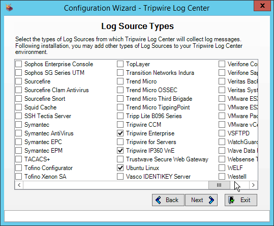
Click Next.
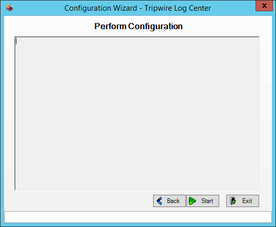
Click Start.
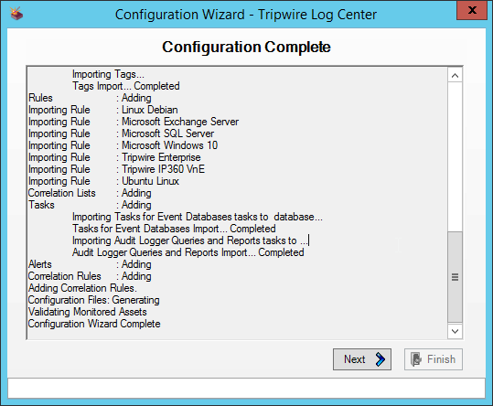
Click Next.
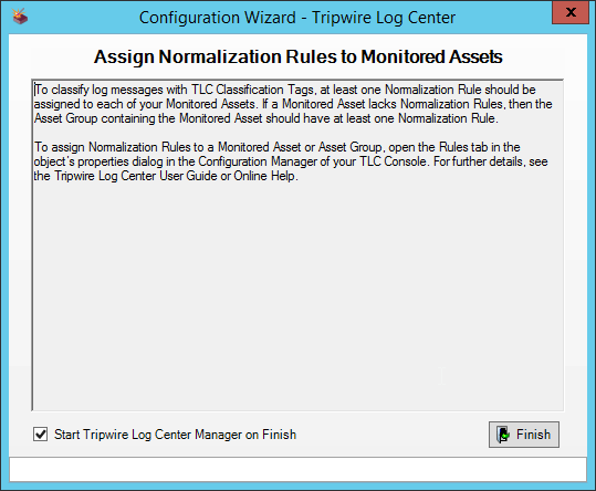
Click Finish.
2.10.3 Install Tripwire Log Center Console
Chapter 4 of the Tripwire Log Center 7.3.1 Installation Guide details the installation of the Tripwire Log Center Console. Use the Tripwire Log Center Console installer.
You can install this on the same machine as the Tripwire Log Center Manager, if desired.
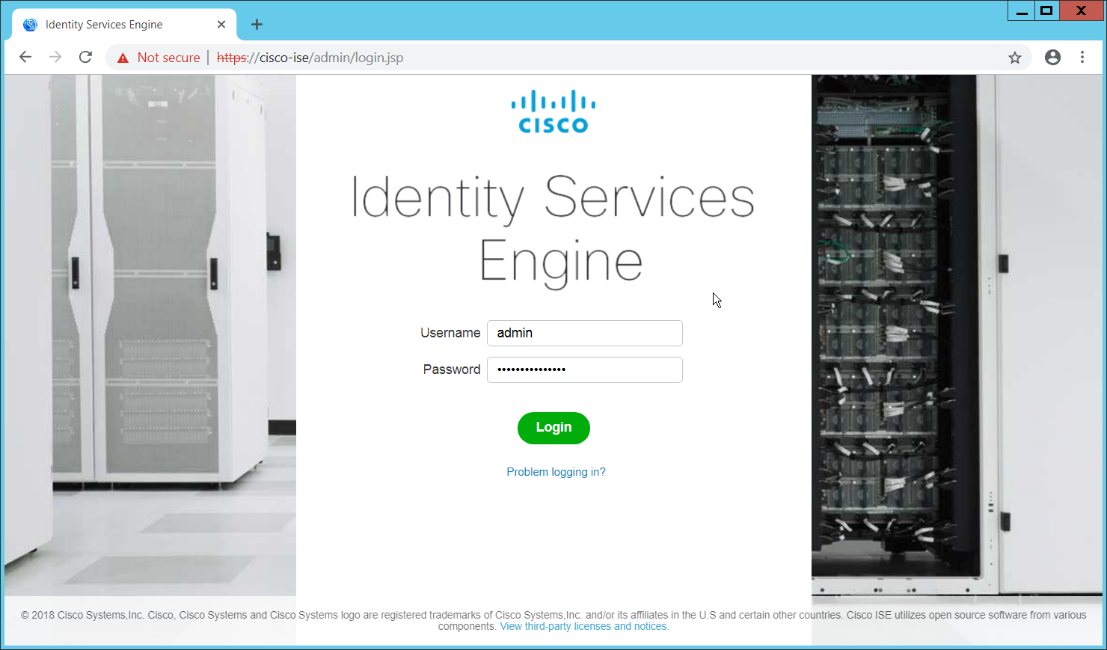
2.11 Cisco Identity Services Engine
This section will detail the installation and some configurations for the Cisco Identity Services Engine (ISE). It assumes the use of the ISE virtual machine.
2.11.1 Initial Setup
When prompted to log in for the first time, enter
setup. (You can use the commandreset-configto change these values later.)Enter the desired hostname for the machine.
Enter the desired IP address for the machine. (Ensure that the specified hostname is associated with this IP address in your DNS.)
Enter the netmask for the machine.
Enter the default gateway.
Enter the default DNS domain (the name of your domain).
Enter the primary nameserver (the IP address of your DNS).
Enter a second nameserver if desired.
Enter an NTP time server.
Enter the timezone.
Enter Y for SSH service.
Enter an administrator username for the machine.
Enter a password twice.
2.11.2 Inventory: Configure SNMP on Routers/Network Devices
See the corresponding vendor documentation for the correct way to enable SNMP on your network device. Ensure that the community string you choose is considered sensitive, like a password.
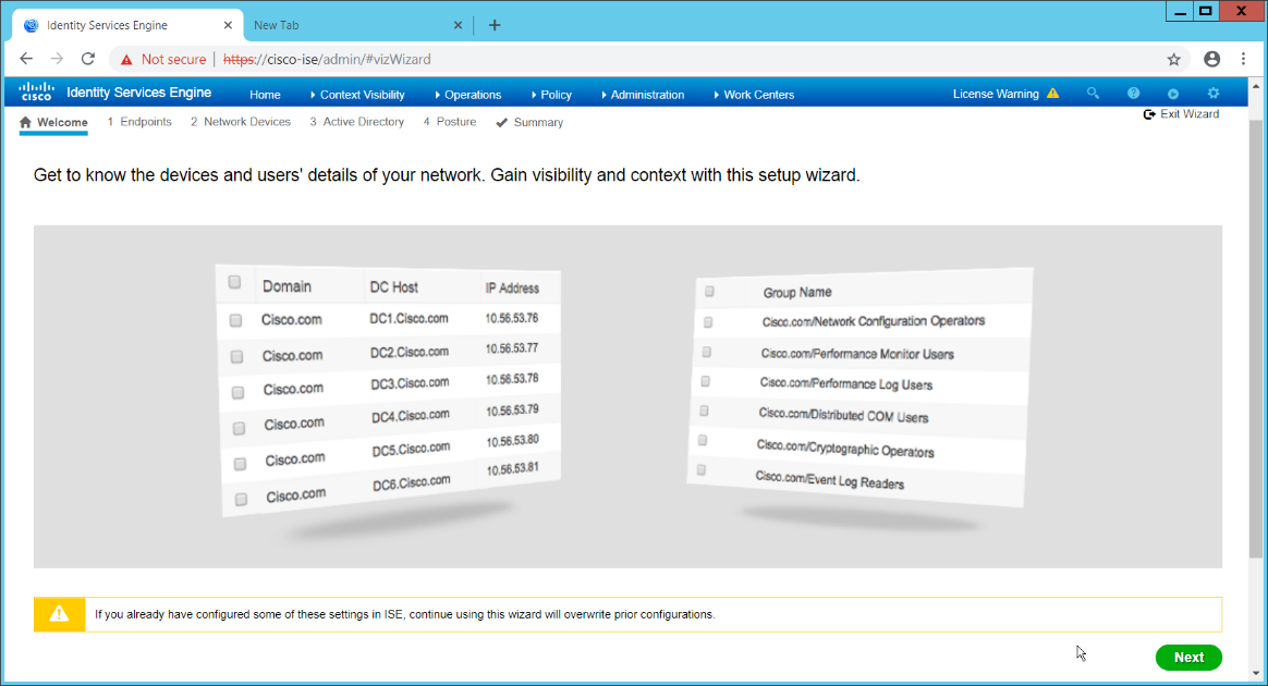
2.11.3 Inventory: Configure Device Detection
Log in to the web client by visiting https://hostname/admin, but replace hostname with the hostname of the ISE machine.
On the top right, use the small play button to select Visibility Setup.
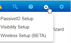
Click Next.
Enter the range of IP addresses to add to ISE’s inventory.
Ensure that Active Scanning is checked.
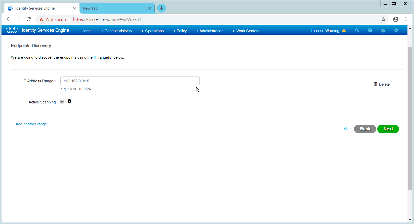
Click Next.
Click the Add Device Manually link.
Enter a name.
Enter the IP address of the network device you configured for SNMP.
Select 1 for SNMP version.
Enter the community string you created.
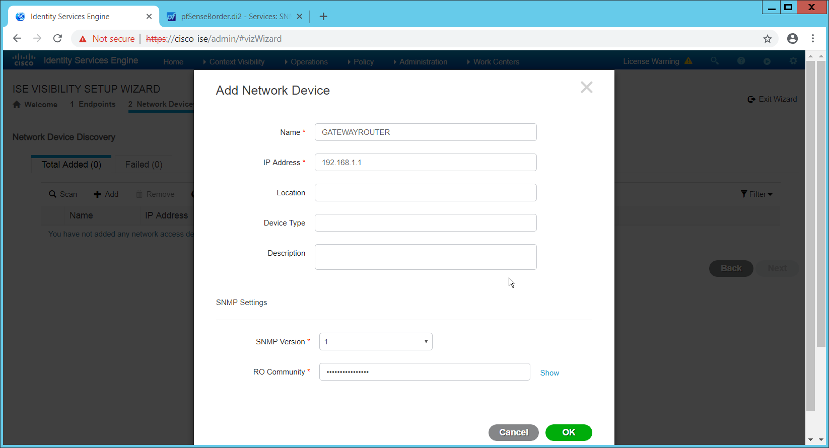
Click OK.
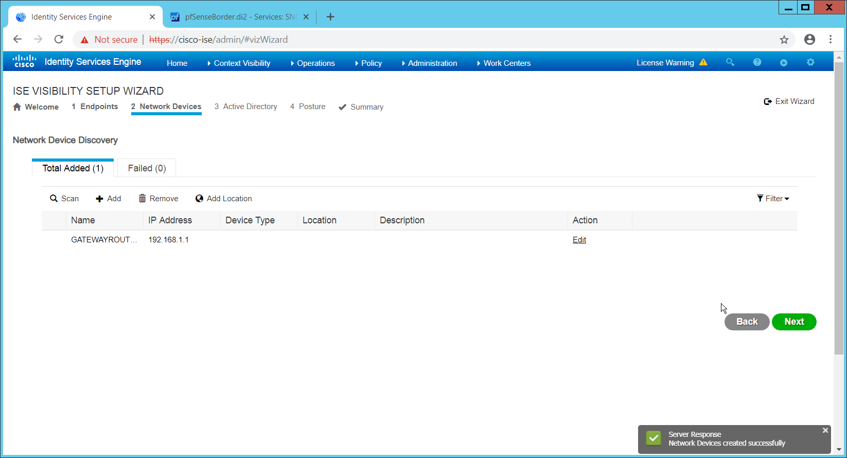
Click Next.
Enter a display name.
Enter the domain name.
Enter the hostname of Cisco ISE.
Enter a username and password.
Click Test Connection to ensure that this works.
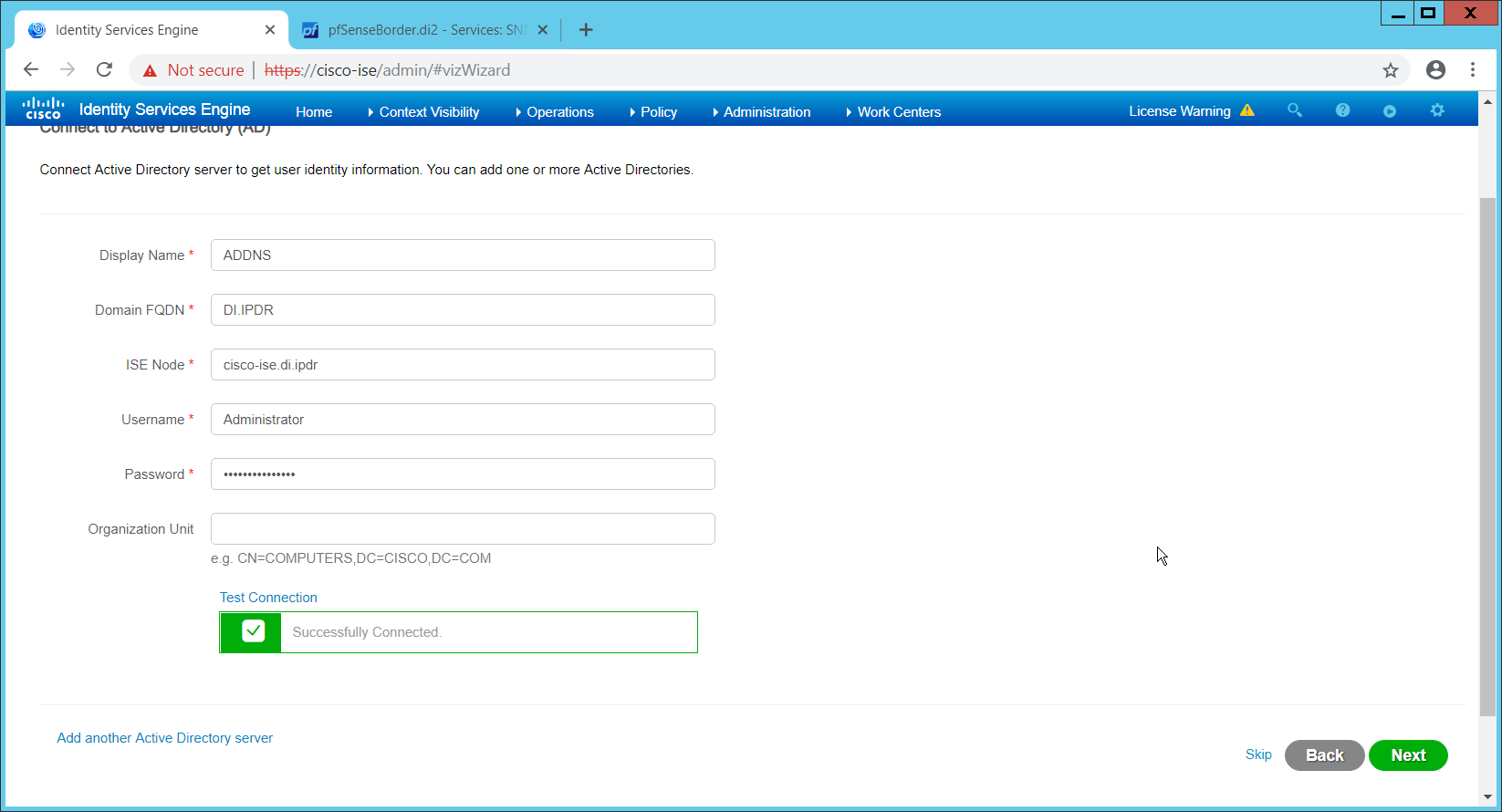
Click Next.
Enter a username and password.
Check the box next to Enable Endpoint Logging.
Check the box next to Include Range.
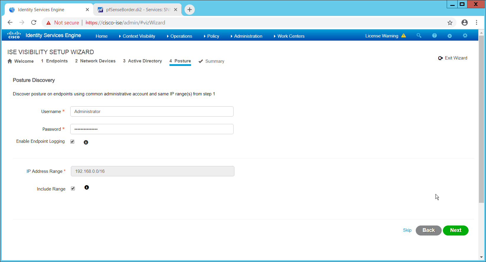
Click Next.
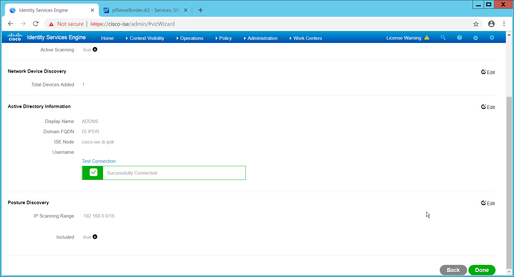
Verify the settings, and click Done. (This should begin importing endpoints connected to the network device, and they will be visible on the ISE dashboard.)
2.11.4 Policy Enforcement: Configure Active Directory Integration
Navigate to Administration > Identity Management > External Identity Sources > Active Directory.
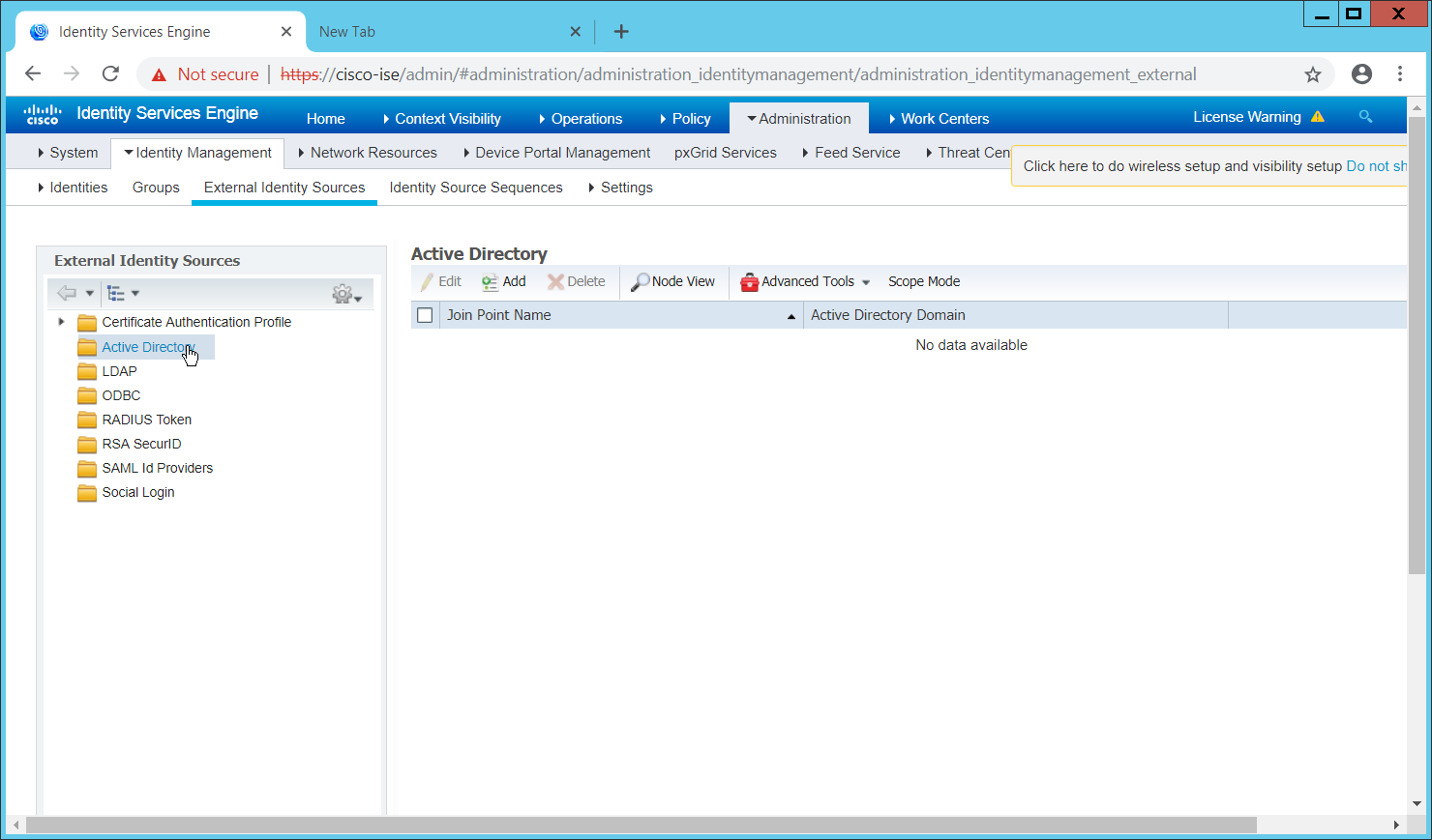
Click Add.
Enter a name.
Enter the domain.
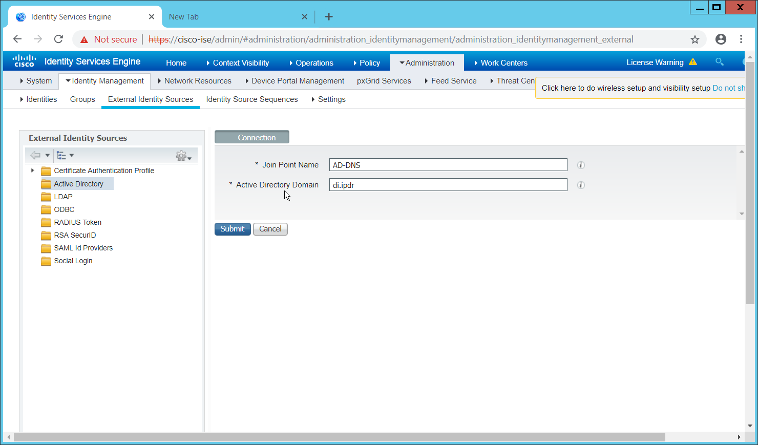
Click Submit.
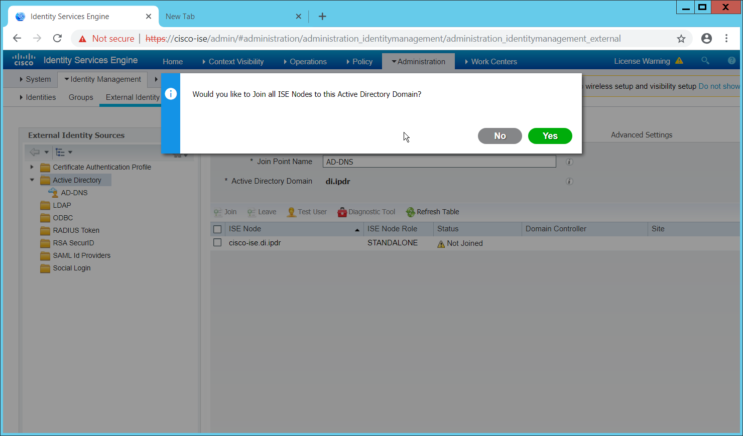
Click Yes.
Enter a username and password to join ISE to the domain.
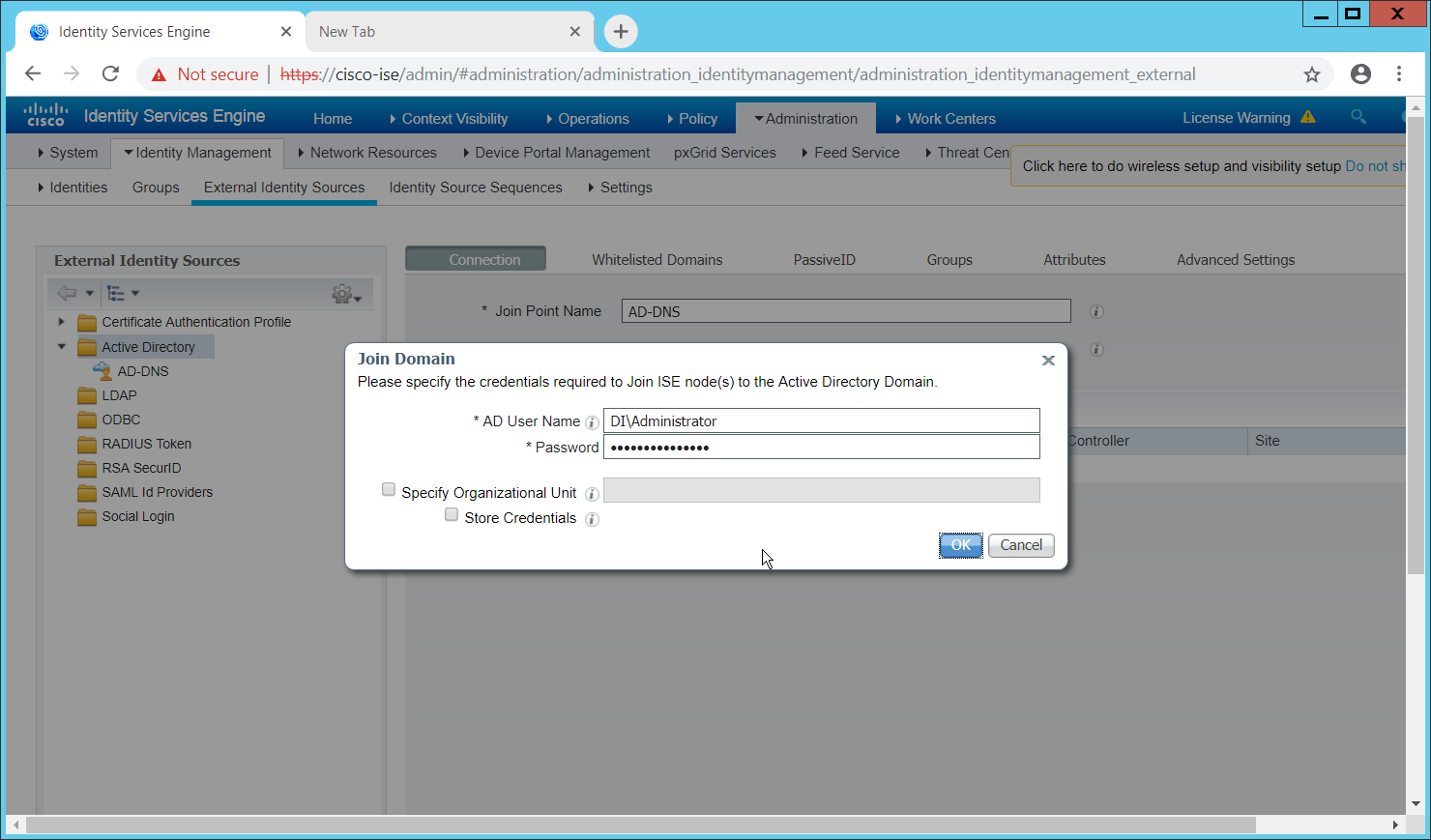
Click OK.
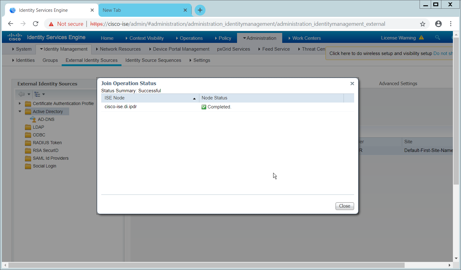
Click Close when the join is finished.
2.11.5 Policy Enforcement: Enable Passive Identity with AD
This configuration allows users to use Active Directory usernames/passwords as authentication for the portal. The web portal will allow clients to download profiling software to ensure that clients have up to date software and can be trusted on the network.
Navigate to Administration > System > Deployment.
Check the box next to ISE.
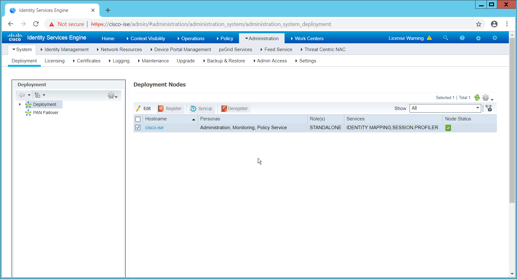
Click Edit.
Check the box next to Enable Passive Identity Service.
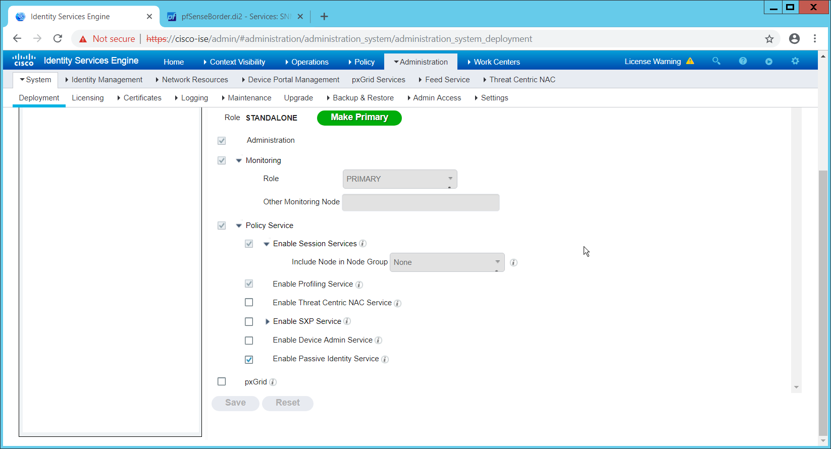
Click Save.
Navigate to Administration > Identity Management > External Identity Sources > Active Directory.
Click the name of the Active Directory machine.
Check the box next to the join point you just created.
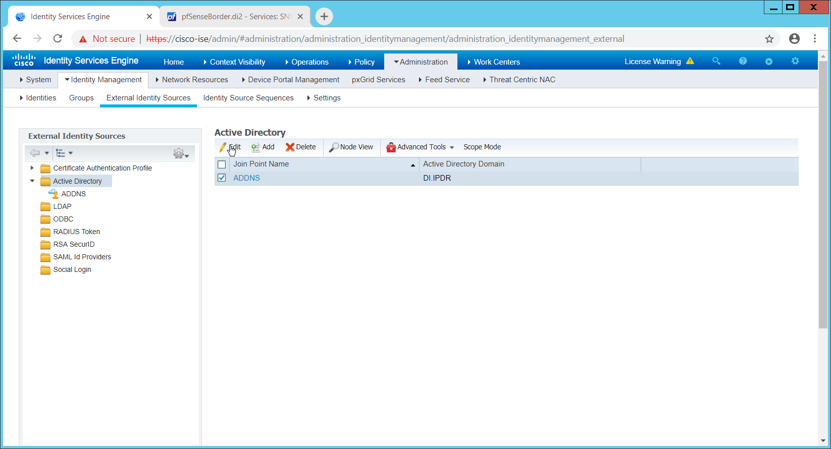
Click Edit.
Click the PassiveID tab.
Click Add DCs if there are no domain controllers listed.
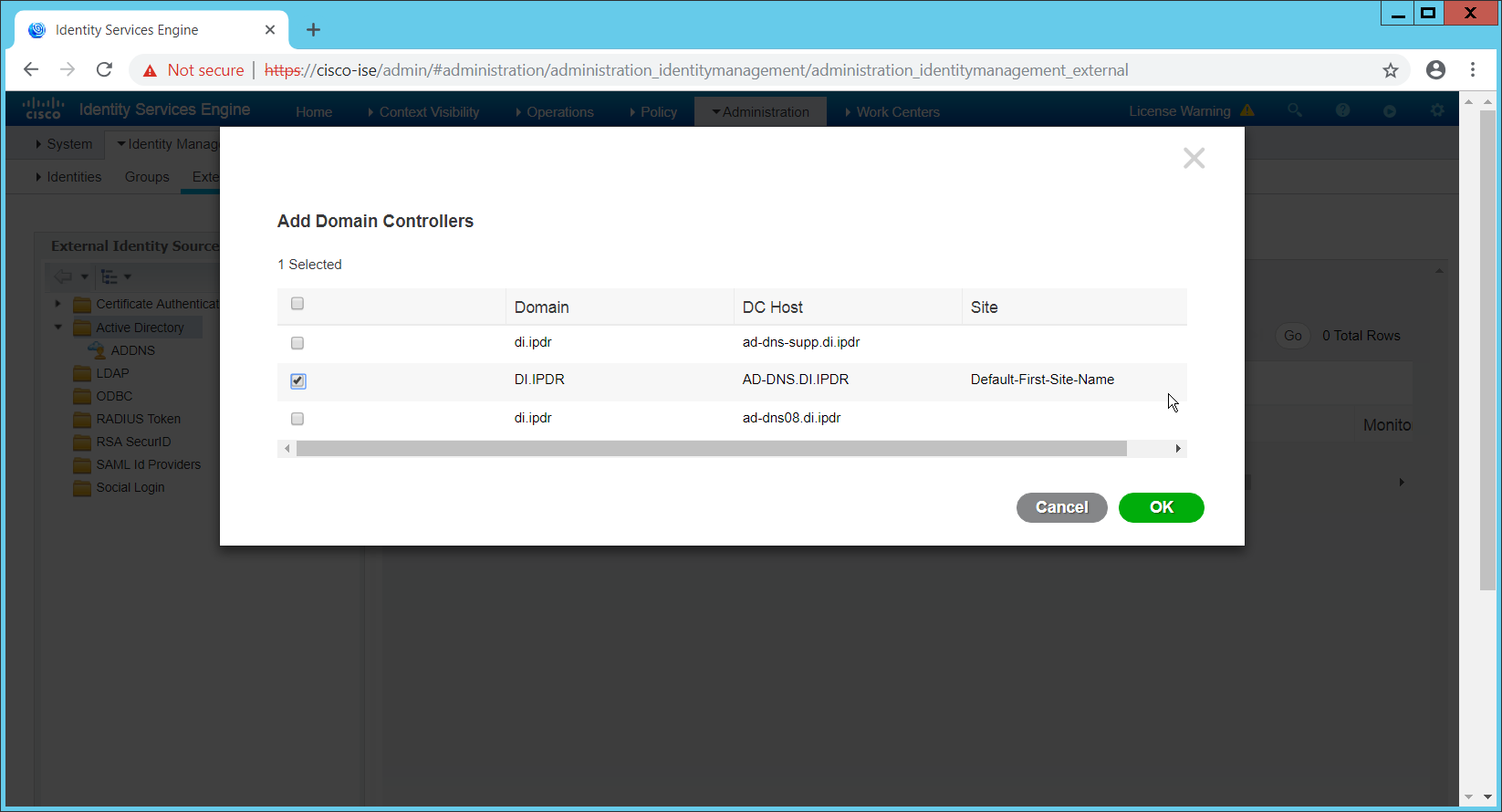
Select the Active Directory domain controller.
Click OK.
Check the box next to the selected domain controller.
Click Edit.
Enter credentials for an administrator account.
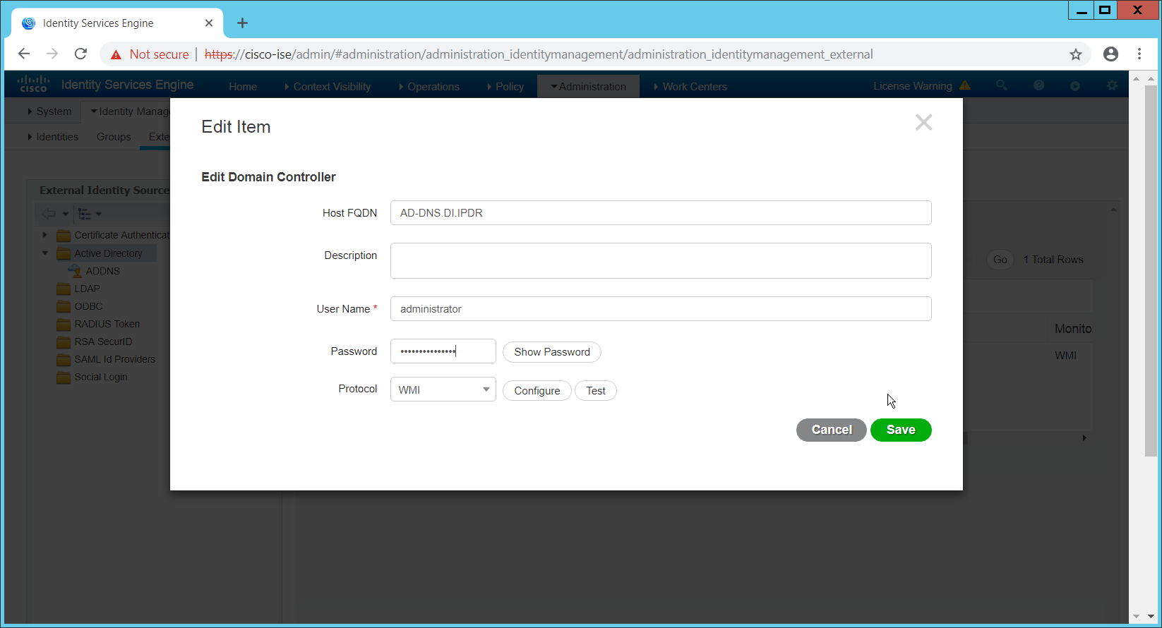
Click Save.
Click Config WMI.
Click OK.
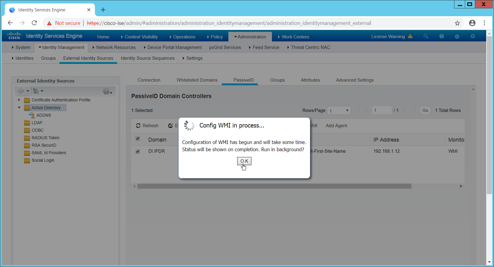
Click OK when this configuration finishes.
Navigate to Administration > System > Settings > Client Provisioning.
Set Enable Automatic Download to Enable.
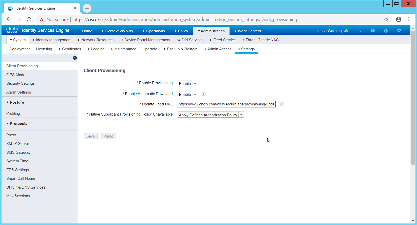
Click Save.
Navigate to Administration > Identity Management > External Identity Sources > Active Directory.
Click the Groups tab.
Click Add > Select Groups from Directory.
Click Retrieve Groups. (This should populate the window with the groups from Active Directory.)
Select them all.
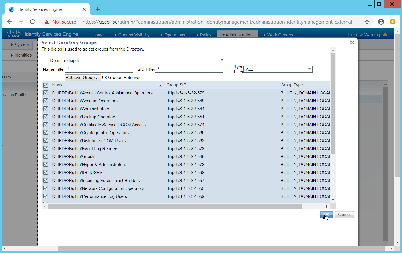
Click OK. (If you add more groups to Active Directory, they can be imported in the same way in the future.)
Click the Attributes tab.
Click Add > Select Attributes from Directory.
Enter a username.
Click Retrieve Attributes. (This will populate the window with Active Directory’s available attributes, so they can be used for policy in Cisco ISE.)
Click OK.
Select any desired attributes.
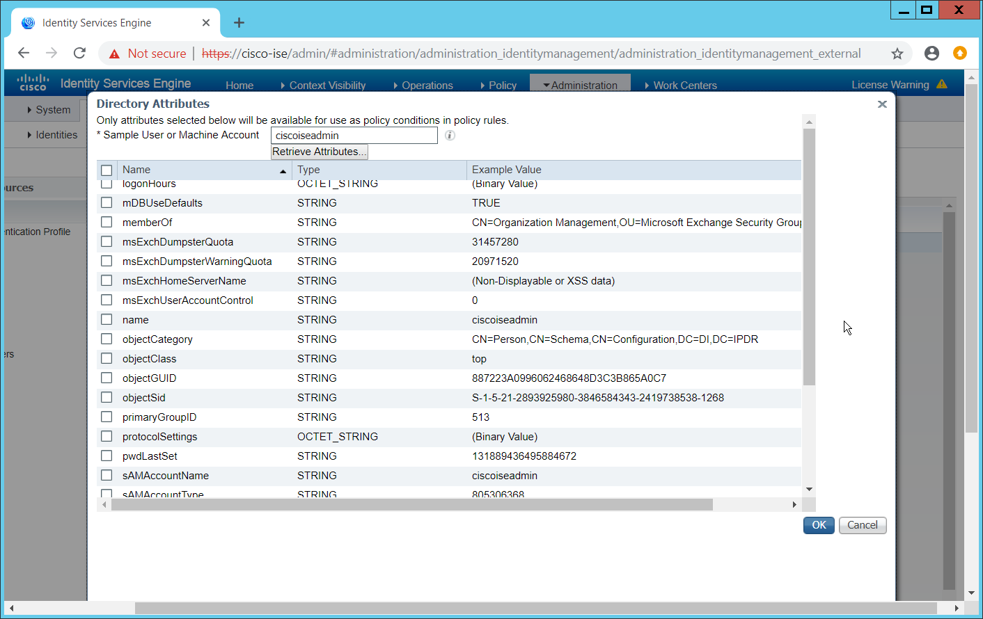
Click OK.
Click Save.
2.11.6 Policy Enforcement: Developing Policy Conditions
Navigate to Policy > Policy Elements > Conditions > Posture.
Expand the Posture section. This will reveal a list of categories for conditions. (Note: these conditions allow you to select or define requirements that endpoints should meet. In typical enterprises these conditions can be used as requirements to gain network access; however, this strongly depends on the capabilities of your network device. Furthermore, the network device
As an example, we will require that Cisco AMP be installed on all Windows devices. If you are using a different anti-malware software, locate that instead. Click Anti-Malware Condition.
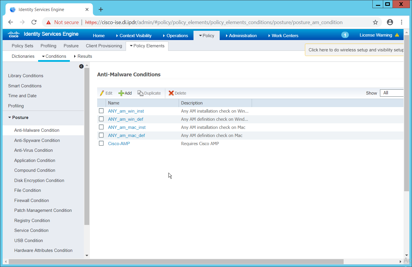
Click Add.
Enter a name.
Enter a description if desired.
Select Windows All for Operating System.
Select Cisco Systems, Inc. for Vendor.
Under Products for Selected Vendor, check the box next to Cisco Advanced Malware Protection, with the version number you have installed.
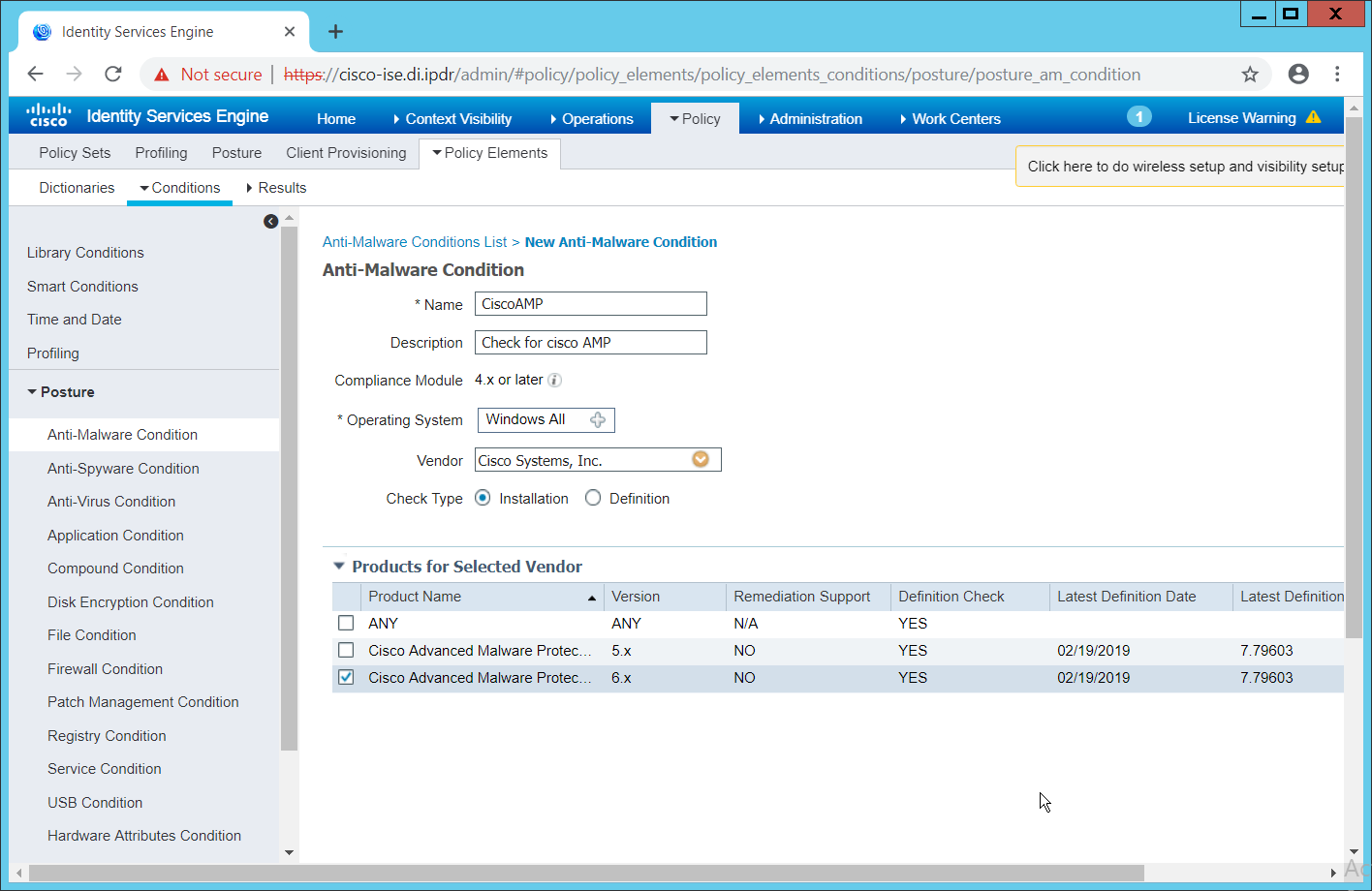
Click Submit.
2.11.7 Policy Enforcement: Developing Policy Results
Navigate to Policy > Policy Elements > Results > Posture > Requirements.
Click one of the black arrows next to the Edit link, and select Insert New Requirement.
Enter a name.
Select Windows All for Operating Systems.
Select 4.x or later for Compliance Module.
Select Temporal Agent for Posture.
Select User Defined Conditions > Anti-Malware Condition > Cisco AMP (substitute “Cisco AMP” with the name of the condition you just created).
Select Message Text Only for the Remediation Action. (Other remediation actions can be defined by going to Policy > Policy Elements > Results > Posture > Remediation Actions, but there is no option for Cisco AMP to be installed, so we leave the default for now.)
Enter a Message to show to the user to inform them that they must install Cisco AMP.
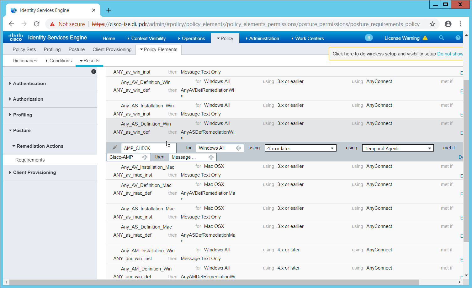
Click Save.
2.11.8 Policy Enforcement: Enforcing a Requirement in Policy
Navigate to Policy > Posture.
Click one of the black arrows next to the Edit link and select Insert New Policy.
Enter a name.
Select Windows All for Operating Systems.
Select 4.x or later for Compliance Module.
Select Temporal Agent for Posture Type.
Select Cisco AMP (substitute “Cisco AMP” with the name of the requirement you just created).
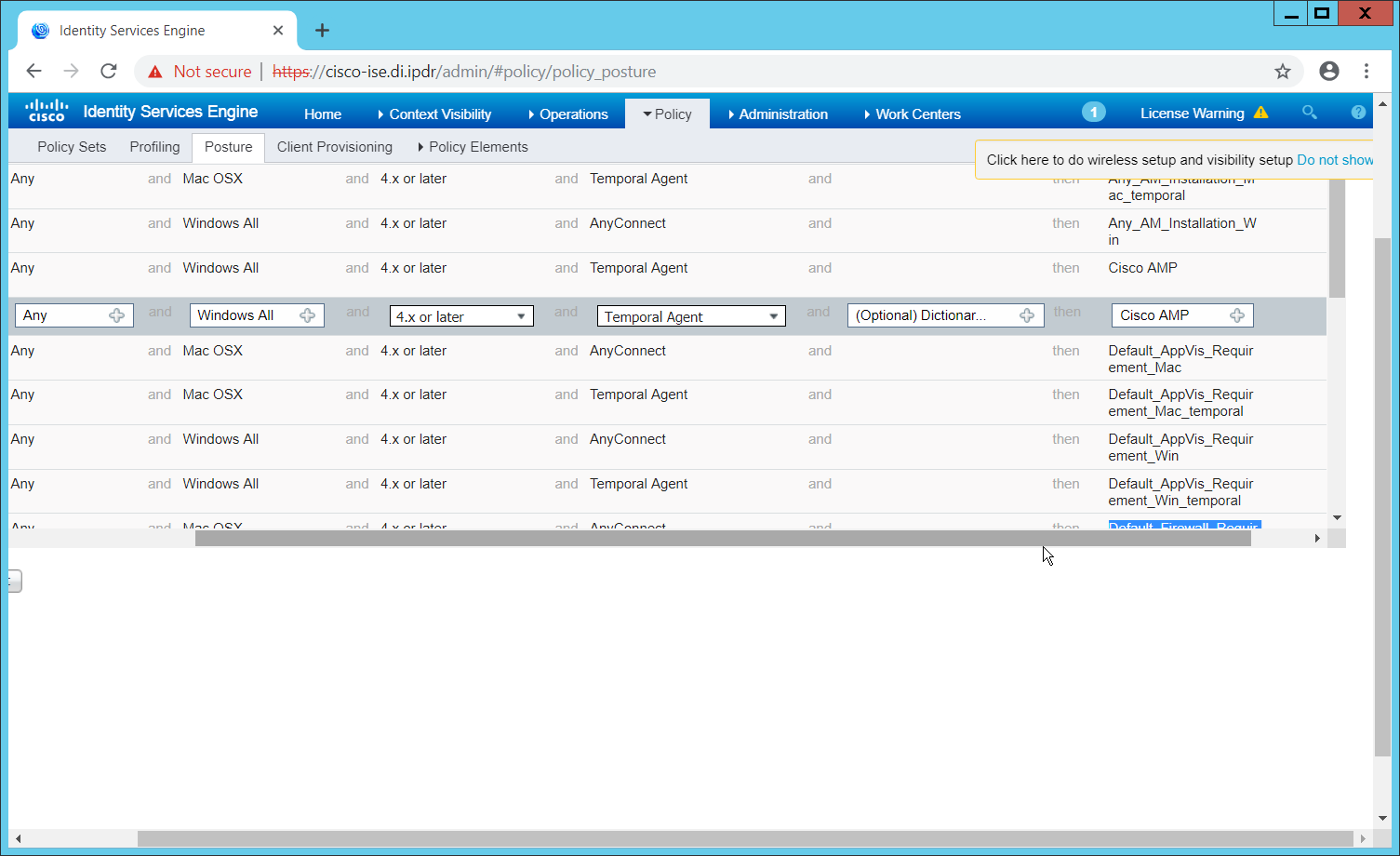
Click Done.
Ensure that the green checkboxes next to the rules you wish to apply are the only checkboxes enabled, as anything enabled will be enforced.
2.11.9 Policy Enforcement: Configuring a Web Portal
Navigate to Administration > Device Portal Management > Client Provisioning.
Select the Client Provisioning Portal (default).
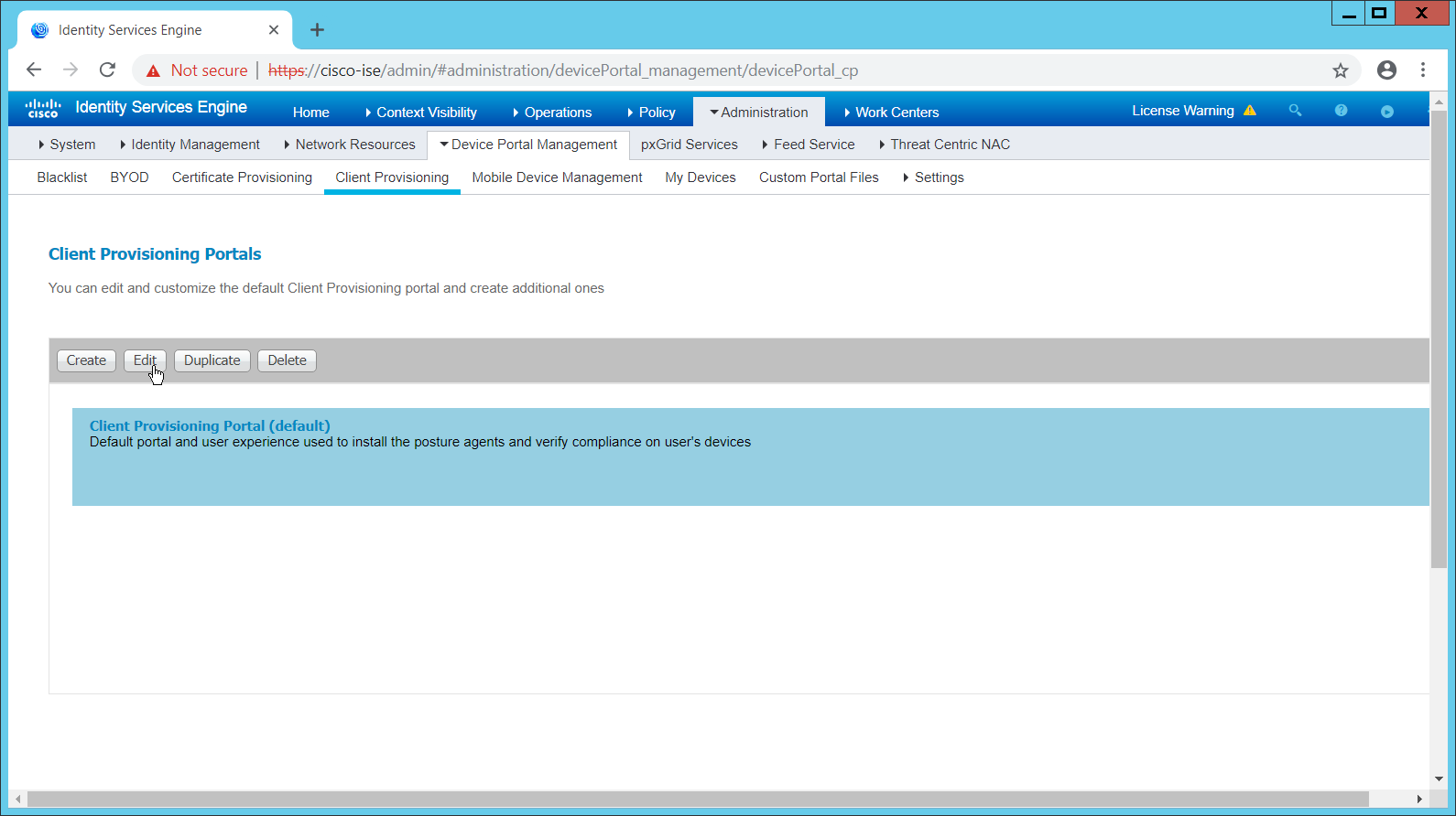
Click Edit.
Under Portal Settings, go to Configure authorized groups, and select the groups that should require a Cisco ISE client.
Enter a domain name for FQDN, and add it to your DNS.
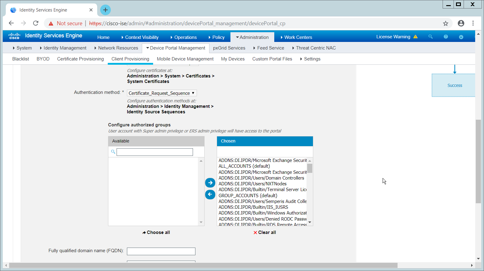
Click Save.
2.11.10 Configuring RADIUS with your Network Device
Cisco ISE requires a Remote Authentication Dial-In User Service (RADIUS) session for posture to function. Posture refers to ISE’s ability to check that a machine complies with a specified policy, which may be based on the OS and may contain requirements such as the installation of certain security applications or the presence of configuration files. Machines that are not in compliance can be kept separated from the network. The process for setting this up varies widely between machines, but the overall requirements have commonalities between systems.
The Network Device (i.e. the router or switch) must support RADIUS functions, specifically Authentication, Authorization, and Accounting. Furthermore, it must also support CoA, which is Change of Authorization.
To configure this, you must configure your network device to use Cisco ISE as a Radius Server. What this means is that your network device will forward authentication requests to Cisco ISE, and Cisco ISE will respond with an “accept” or “reject.”
The Network Device must support some form of 802.1x. Note that this is not supported on certain routers, even if RADIUS is supported. 802.1x is a mechanism for authenticating the end workstation to the network device, potentially over wireless or through ethernet.
This can take various forms, such as a captive web portal, Media Access Control (MAC) address authentication, or user authentication. A captive web portal, if the device supports it, may be ideal for configuration without the correct hardware.
There are also many switches that provide direct 802.1x username/password authentication. Note that if you choose to use this mechanism, a client is still required, and it will not be in the web browser. Windows has a built-in 802.1x client that can be configured on Network adapters under the Authentication tab. To enable it, you must first start the service Wired AutoConfig, and then the Authentication tab will become available for configuration.
Whichever form of 802.1x is chosen, the request for authentication must be forwarded to Cisco ISE. Cisco ISE will process the request for authentication.
The two steps above detail the authentication phase. Once authenticated, the network device must redirect the user to the client provisioning portal (or to a guest portal), depending on the setup. The URL for this can be acquired from the active Authorization Profile in ISE.
The user will then authenticate to the Guest Portal or Client Provisioning Portal (depending on your setup). The portal will prompt the user to download an executable, which will run posture.
The executable will first check for the existence of a RADIUS session in Cisco ISE for the user who downloaded the executable. It will primarily check the MAC address that visited the ISE web portal against the MAC addresses of existing sessions. If and only if a session exists, it will run posture based on the policy you set up. You can verify that a session exists by navigating to Operations > RADIUS > Live Sessions.
2.11.11 Configuring an Authentication Policy
Navigate to Policy > Policy Elements > Results > Authentication > Allowed Protocols.
Select the Default Network Access protocol, or create your own.
Ensure any protocols that need to be supported for your network setup are allowed. In particular, if using 802.1x, you should likely check the box next to Allow MS-CHAPv2.
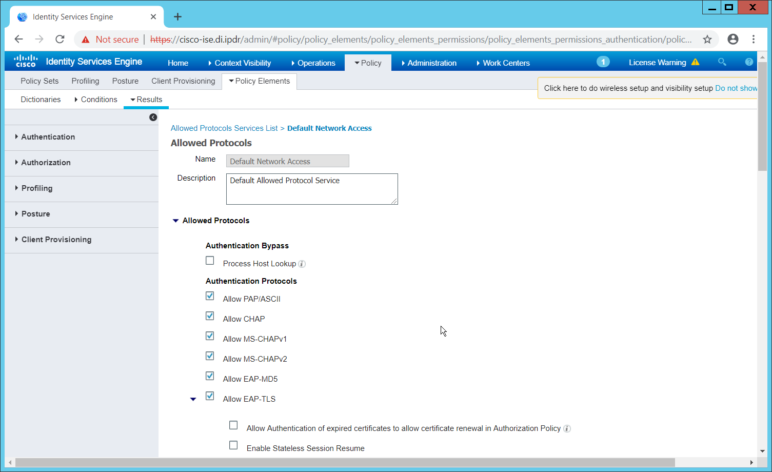
Click Save.
Navigate to Policy > Policy Sets.
Select the default policy.
Ensure that the Allowed Protocol selection matches the allowed protocol you just created/edited.
Expand the Authentication Policy section, and select the ID stores from which to authenticate users. For example, if you set up an Active Directory integration, it may be desirable to authenticate users from there.
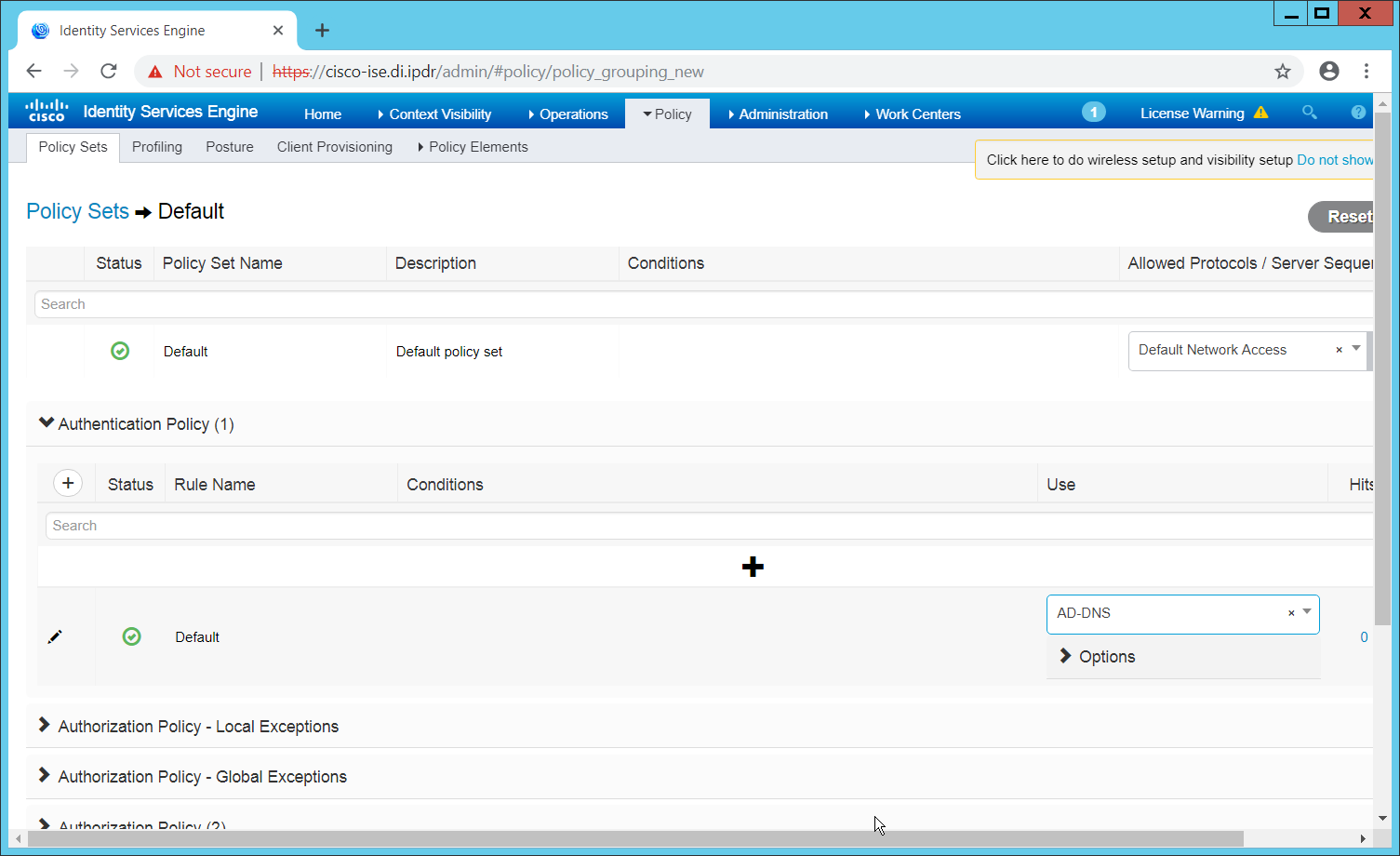
Click Save.
2.11.12 Configuring an Authorization Policy
The Authorization Profile is likely dependent on your network device, but it is possible that the Cisco_Temporal_Onboard profile will work even for non-Cisco devices. You can edit the authorization policy by navigating to Policy > Policy Elements > Results > Authorization > Authorization Profiles.
The temporal onboard profile will attempt to redirect the user to a client provisioning portal–this redirection will most likely only happen automatically on compatible Cisco network devices. If another device is used, the device may need to manually redirect the user to the client provisioning portal after authentication. (We accomplished this in PFSense for our build using a “Post-authentication redirection” feature in the Captive Portal.)
Once you are finished configuring the Authorization Profile, navigate to Policy > Policy Sets.
Select the default policy.
Expand the Authorization Policy section.
Note that you can configure this for as many groups and conditions as desired, potentially specifying different authorization profiles for various user groups or levels of authentication, including unauthenticated access. Under Results > Profiles, you can select the authorization profiles you configured.
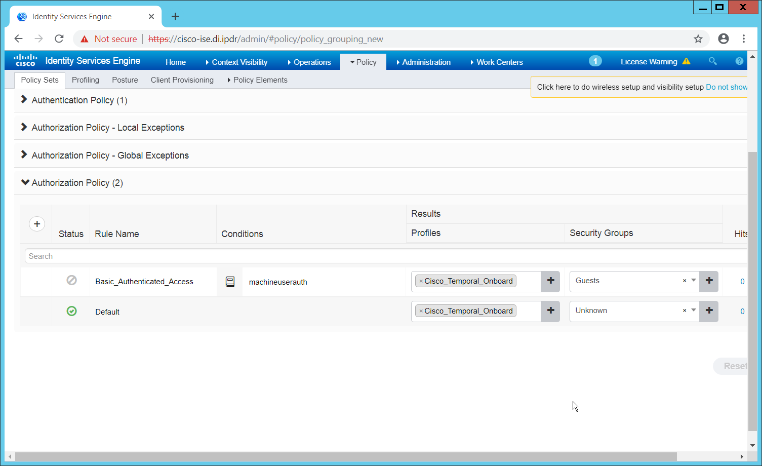
Click Save.
2.12 Cisco Advanced Malware Protection
This section assumes the use of the Cisco Advanced Malware Protection (AMP) Console, a cloud-based server that connects to clients on individual machines. There is some configuration to be done on this cloud-based server, which may impact the installation. Cisco provides best practices guides online for AMP configuration. Here is a link to one such guide: https://www.cisco.com/c/en/us/support/docs/security/amp-endpoints/213681-best-practices-for-amp-for-endpoint-excl.html.
2.12.1 Dashboard Configuration
From the Cisco AMP dashboard, located at https://console.amp.cisco.com/dashboard, click Set Up Windows Connector.
The configuration of this will be different for each enterprise, so consult your Cisco representative for the proper way to set this up. For the purposes of this build, we accepted the default values.
2.12.2 Installing the Connector on a Windows Server
On the Cisco AMP dashboard, navigate to Management > Download Connector.
Select the AMP group in which to put the machine. For example, when installing on an Active Directory machine, we chose Domain Controller.
Find the correct OS version of the installer, and click Download.
Run the downloaded executable (for example, Domain_Controller_FireAMPSetup.exe).
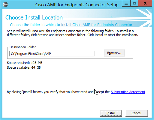
Click Install.
Click Next.
Click Close.
2.12.3 Installing the Connector on a Windows 10 Machine
On the Cisco AMP dashboard, navigate to Management > Download Connector.
Select the AMP group in which to put the machine. For this installation we chose Protect.
Find the correct OS version of the installer, and click Download.
Run the downloaded executable (for example, Protect_FireAMPSetup.exe).
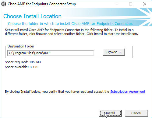
Click Install.
Click Next.
Click Close.
2.12.4 Scanning using AMP
If the AMP software does not run automatically, open it from the start menu.
Click Scan Now.
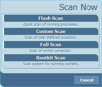
Click Full Scan.
A scan should begin.
2.12.5 Configure AMP Policy
On the web console, navigate to Management > Policies.
Select a policy to edit; for this example, we choose Domain Controllers. (To edit which policies map to which groups, select Management > Groups, and click Edit on the group for which you wish to select a policy. You can select a policy for each Operating System (OS) in that group.)
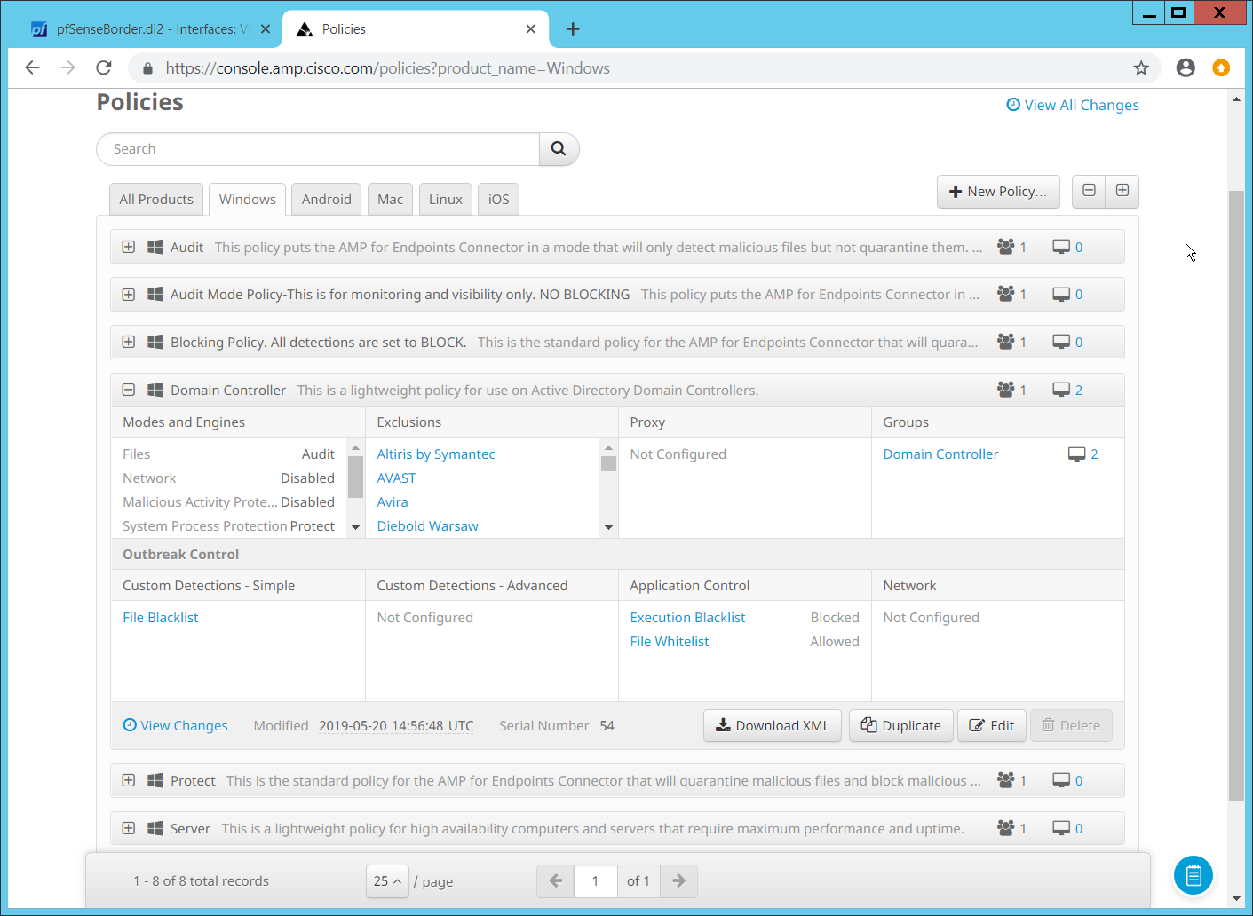
Click Edit.
In the Modes and Engines tab, “Conviction Modes” refers to the response taken to various detected suspicious activity or files.
Audit is a detection/logging approach that does not take any action other than logging the activity.
Quarantine involves the move of the offending file to its own folder, where it is monitored and deleted after a certain amount of time. Quarantining can also be applied to processes, in which the process is monitored and prevented from affecting system operations.
Block involves the deletion of the file or the stopping of the process or network traffic.
“Detection Engines” refer to the actual detection of the suspicious activity.
TETRA is intended to be an anti-malware engine and recommends that it not be used when other antimalware software is in use.
Exploit Prevention refers to an engine that defends endpoints against memory injection attacks.
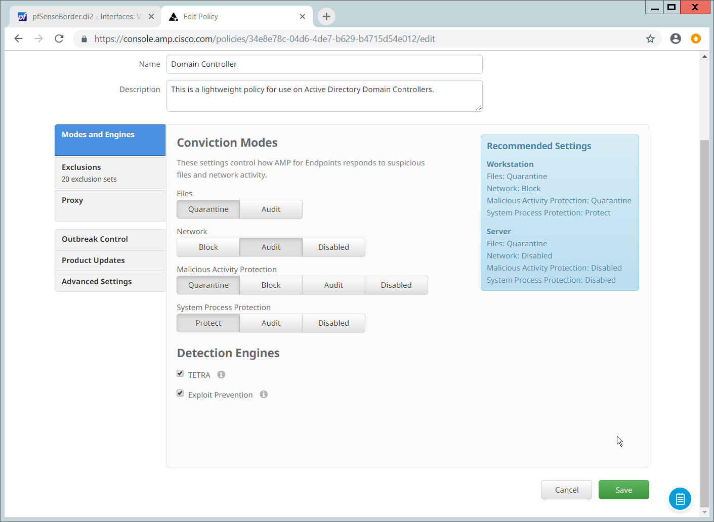
Click Save.
2.13 Cisco Stealthwatch
This section will describe the setup and configuration of Cisco Stealthwatch, a network monitoring solution. This guide assumes the use of the Stealthwatch virtual machines.
2.13.1 Configure Stealthwatch Flow Collector, Stealthwatch Management Console, Stealthwatch UDP Director and Stealthwatch Flow Sensor
Log in to the console of Stealthwatch Flow UDP Director.
Navigate the menu to highlight Management and Select.
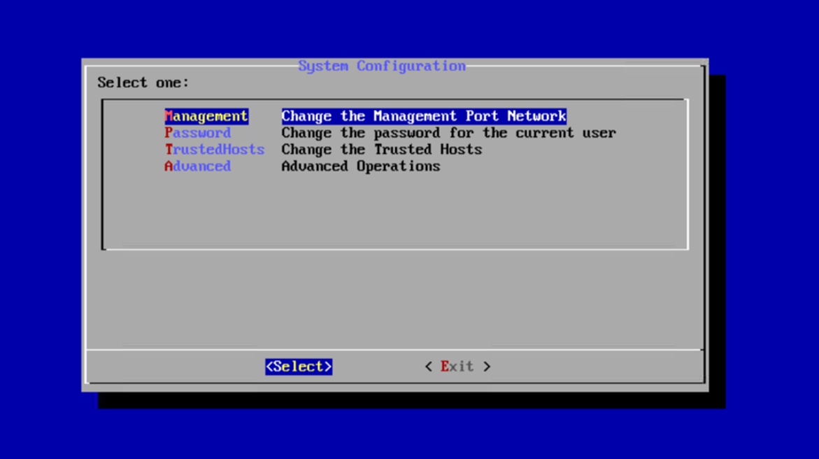
Press Enter.
Enter an IP Address for this machine.
Highlight OK.
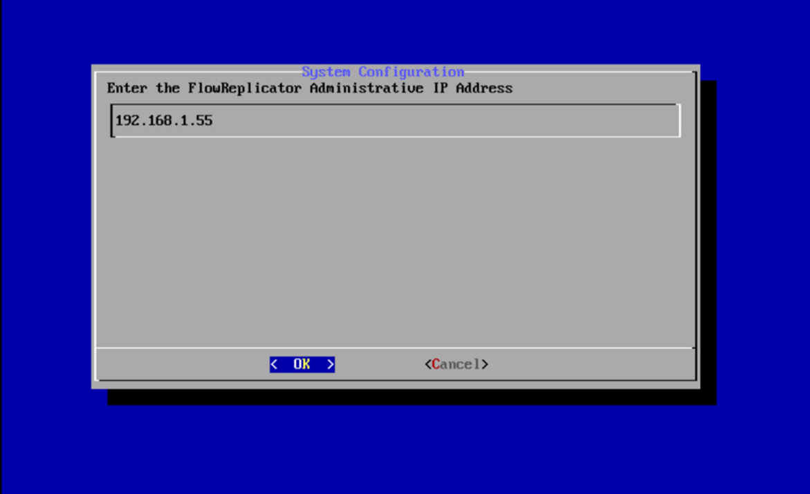
Press Enter.
Enter a network mask for the IP Address.
Highlight OK.
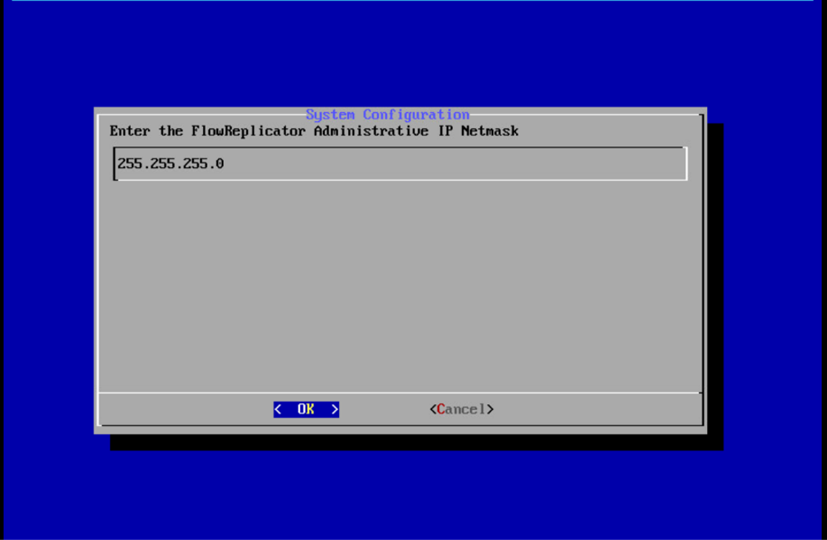
Press Enter.
Enter the network gateway.
Highlight OK.
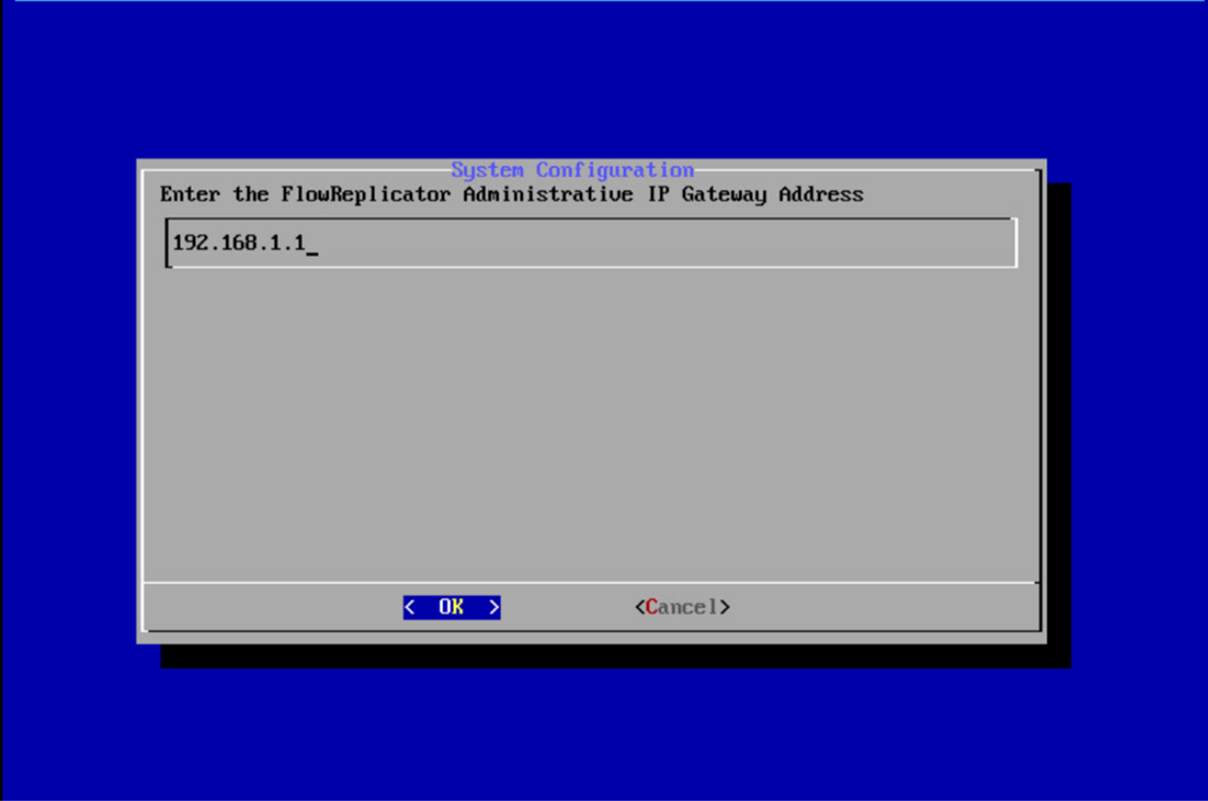
Press Enter.
Enter the network broadcast address.
Highlight OK.
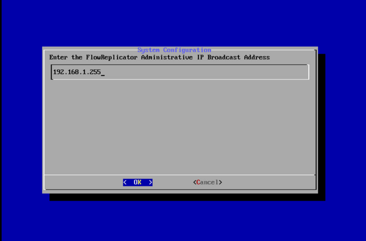
Press Enter.
Highlight Yes.
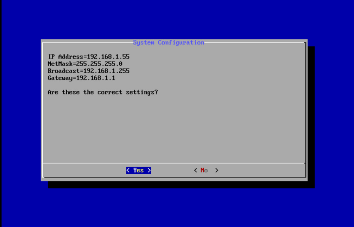
Press Enter.
Highlight OK.
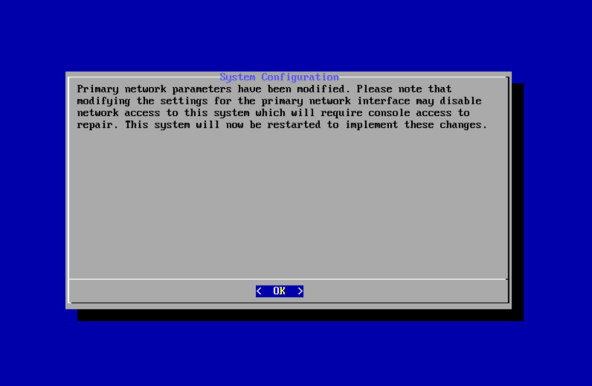
Press Enter.
Repeat steps 1-19 for each of the Stealthwatch Management Console, Stealthwatch UDP Director, Stealthwatch Flow Sensor, and Stealthwatch Flow Collector.
2.13.2 Change Default Stealthwatch Console Passwords
In the System Configuration menu, highlight Password and Select.
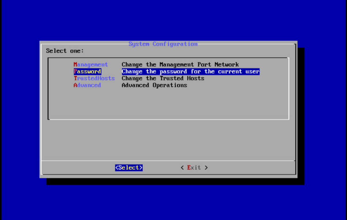
Press Enter.
Enter the original password.
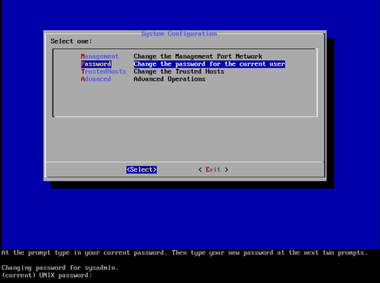
Press Enter.
Enter the new password, and confirm it.
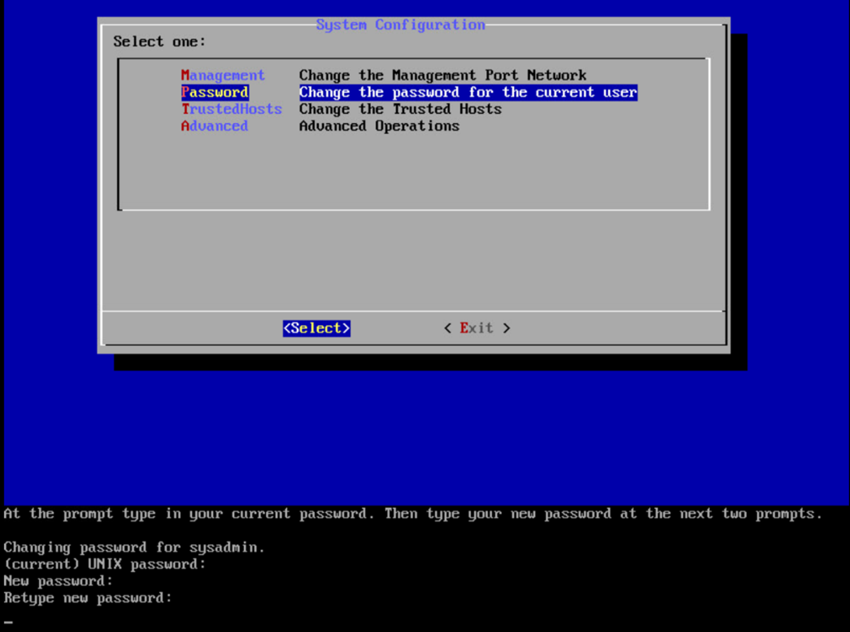
Press Enter.
In the System Configuration menu, highlight Advanced and Select.
Press Enter.
Highlight RootShell and Select.
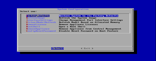
Press Enter.
Log in using the original root shell password.
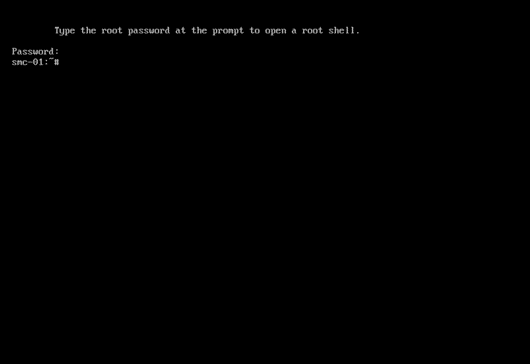
Enter the command
root.Type the new password, and confirm it.
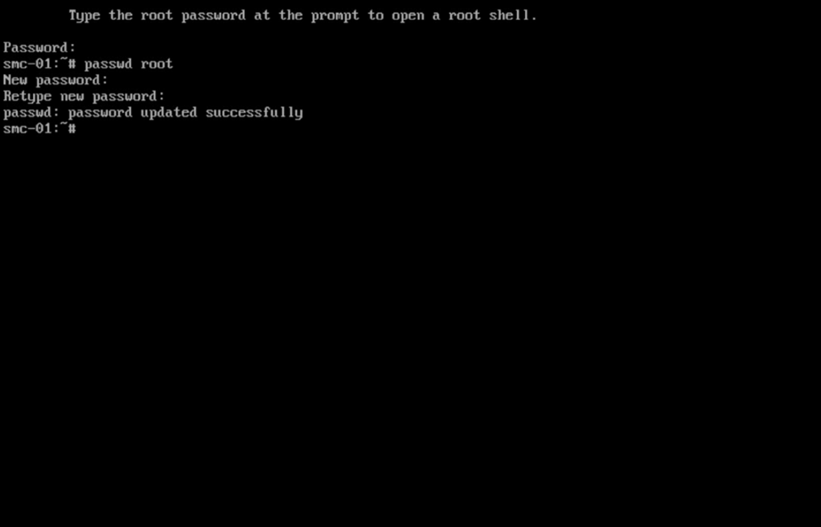
Press Enter.
Repeat steps 1-14 for each console.
2.13.3 Configure the Stealthwatch Management Console Web Interface
Change the default password by filling in the fields for Current Password, New Password, and Confirm New Password.
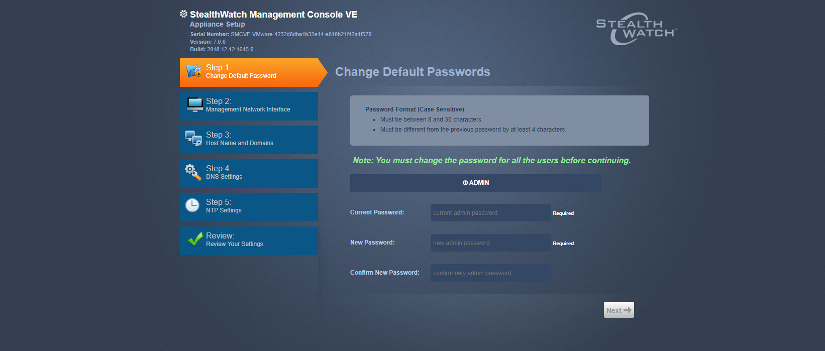
Click Next.
Fill in the fields for IP Address, Subnet Mask, Default Gateway and Broadcast Address according to your network topology.
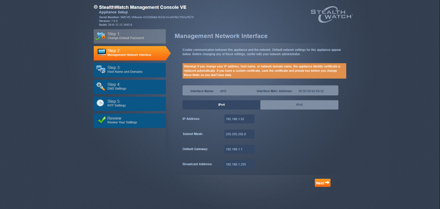
Click Next.
Enter a host name.
Enter the network domain that Stealthwatch is in for Network Domain.
Enter the network domain that Stealthwatch will be monitoring for Stealthwatch Domain.
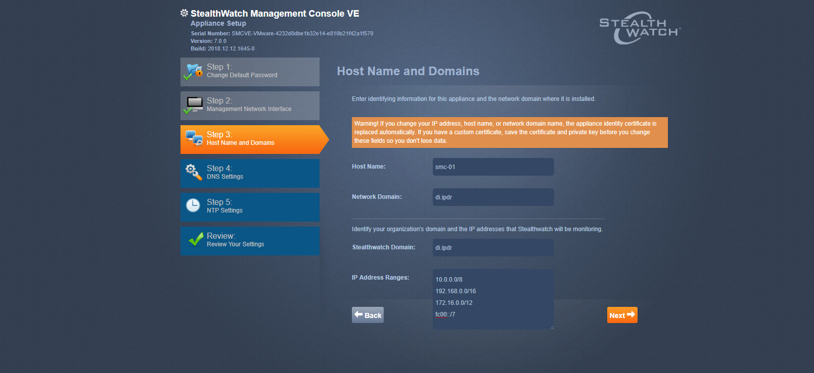
Click Next.
Enter a DNS Server.
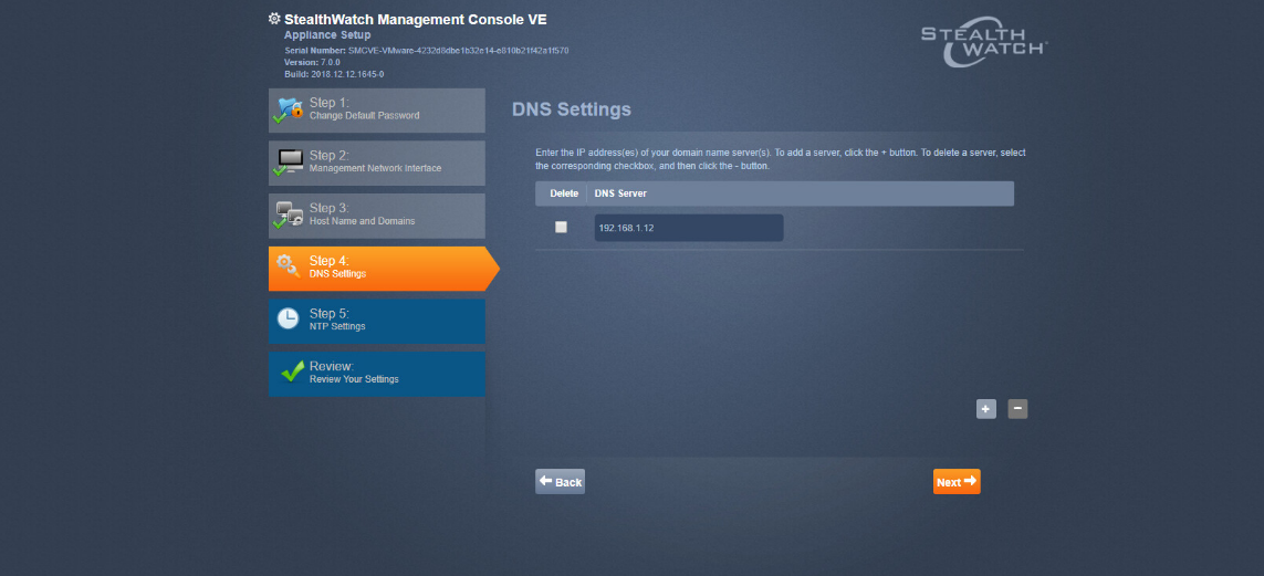
Click Next.
Configure the Network Time Protocol (NTP) server according to your network topology.
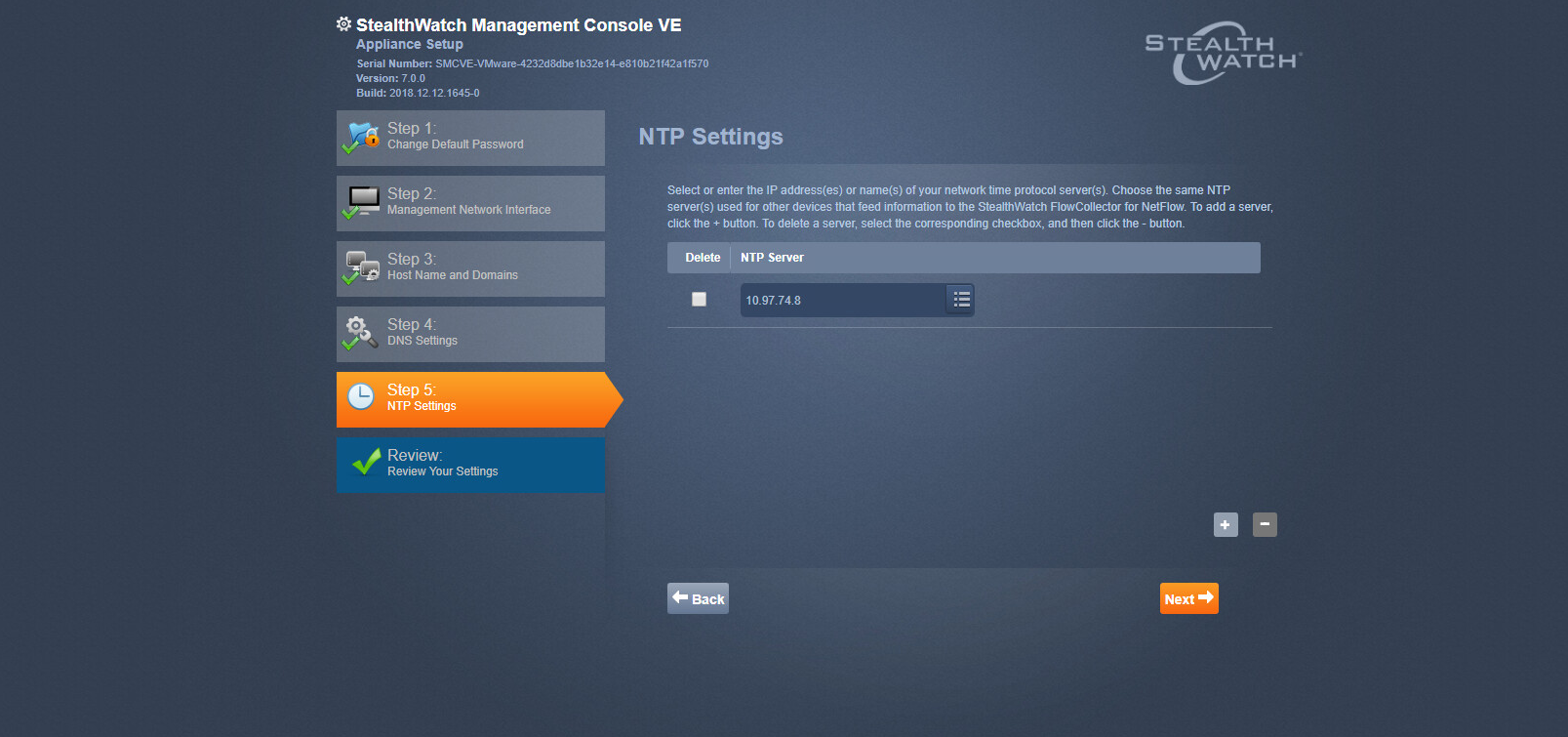
Click Next.
Select Restart.
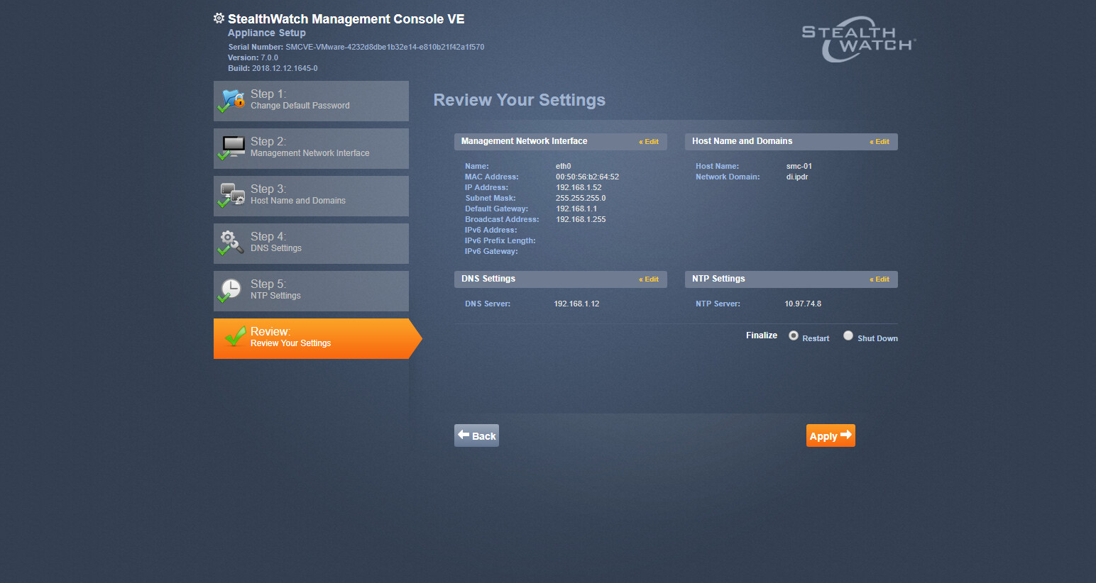
Click Apply.
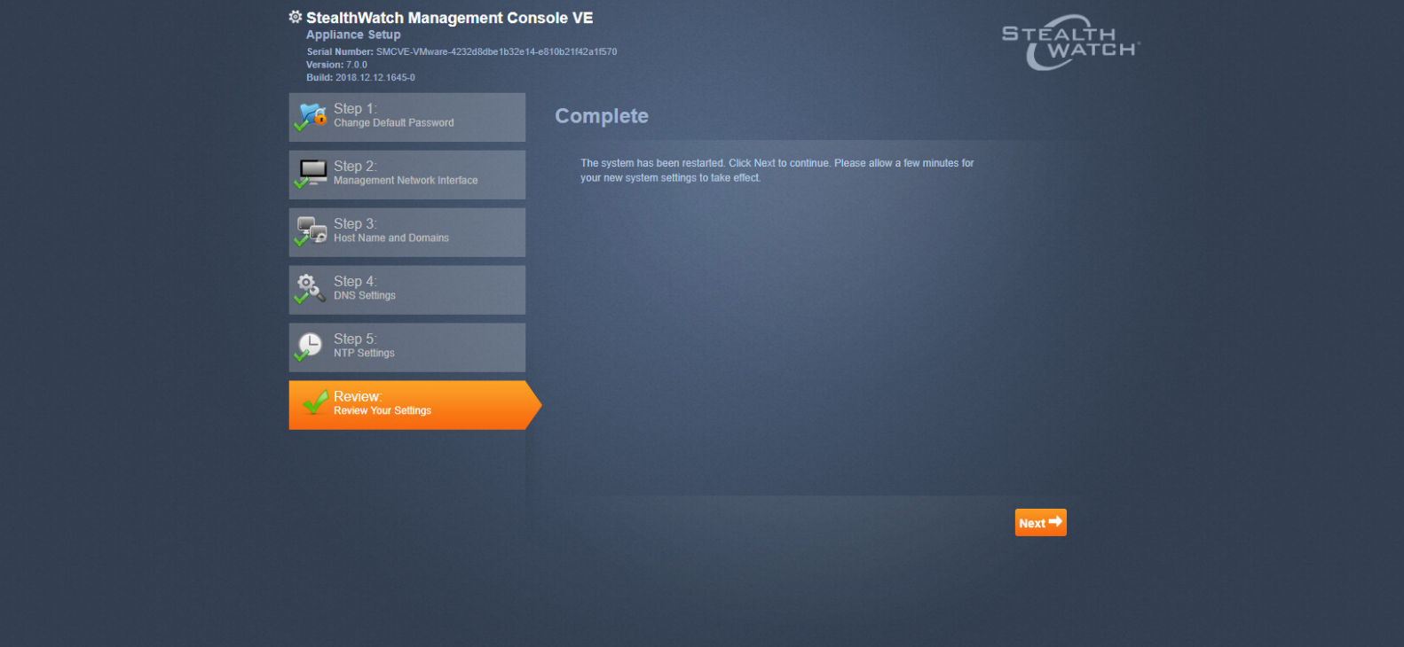
After the restart, click Next.
2.13.4 Configure the Stealthwatch UDP Director, Stealthwatch Flow Collector and Stealthwatch Flow Sensor Web Interfaces
Repeat steps 1-12 from Configure the Stealthwatch Management Console Web Interface.
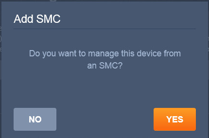
When prompted to manage this device from an SMC, click Yes.
Enter the IP Address of the Stealthwatch Management Console.
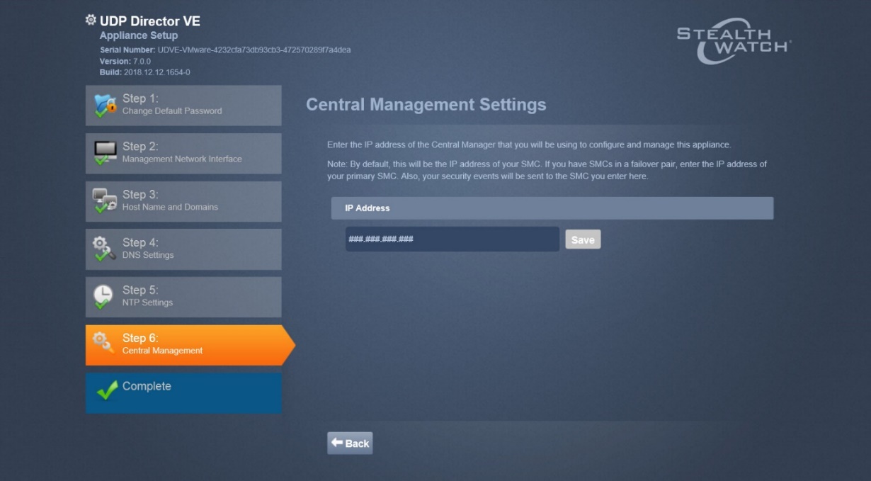
Click Save.
Verify the certificate.
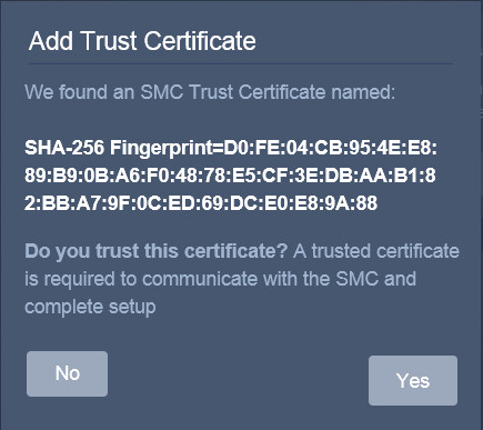
Click Yes.
Enter the User ID and Password for the Stealthwatch Management Console.
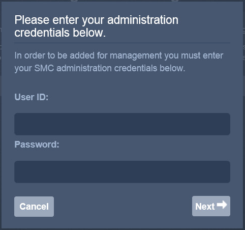
Click Next.
Repeat steps 1-8 for the Flow Collector first and then for the Flow Sensor. The Flow Sensor cannot be added to the Management Console until after the Flow Collector is successfully added.
2.14 Symantec Analytics
This section details the installation and configuration of Symantec Analytics, a network analysis tool. This guide assumes that Symantec Analytics is connected via serial to a terminal.
2.14.1 Initial Setup
Log in to the Symantec Analytics command line.
Enter the following command to configure the IP for the interface:
sudo cfg_bond_interface.py -i eth0 -n 192.168.1.42/255.255.255.0 -g 192.168.1.1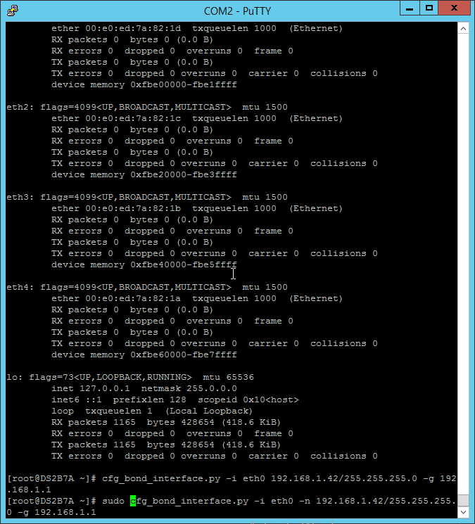
Navigate to the IP you assigned in a browser.
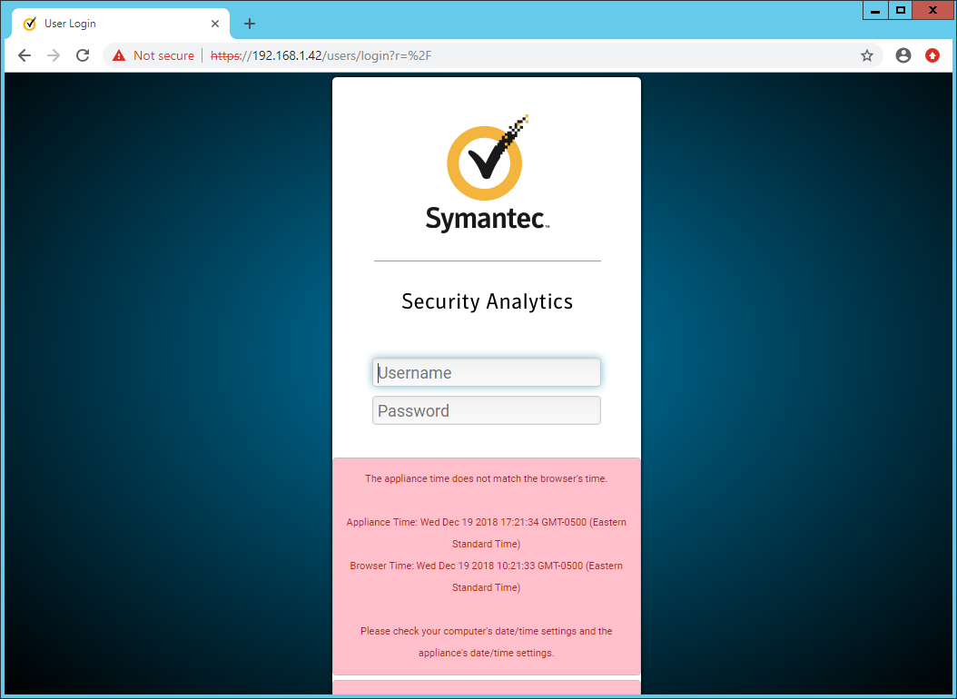
Enter the username and password to log in. The default is (Admin/Solera).
Check the box next to I have read and agreed to the terms of the End User License Agreement on behalf of the end user.
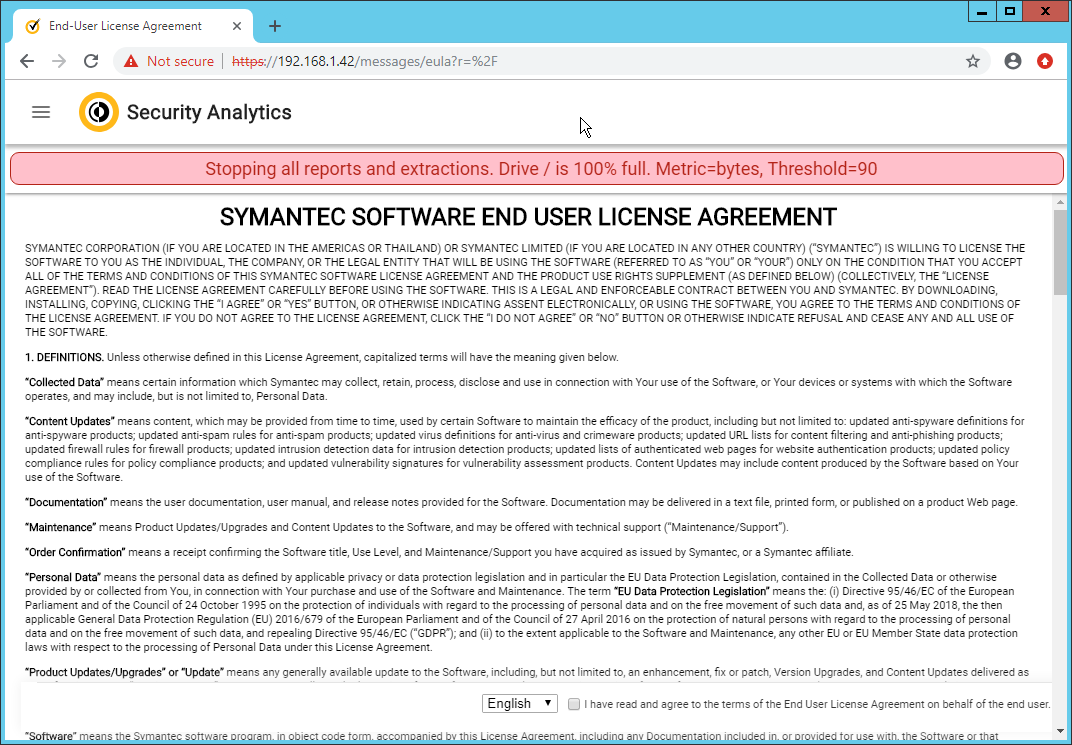
Click Next.
Enter the license key.
If you do not have internet connectivity, follow the instructions under Upload License File. Otherwise, click Send Request.
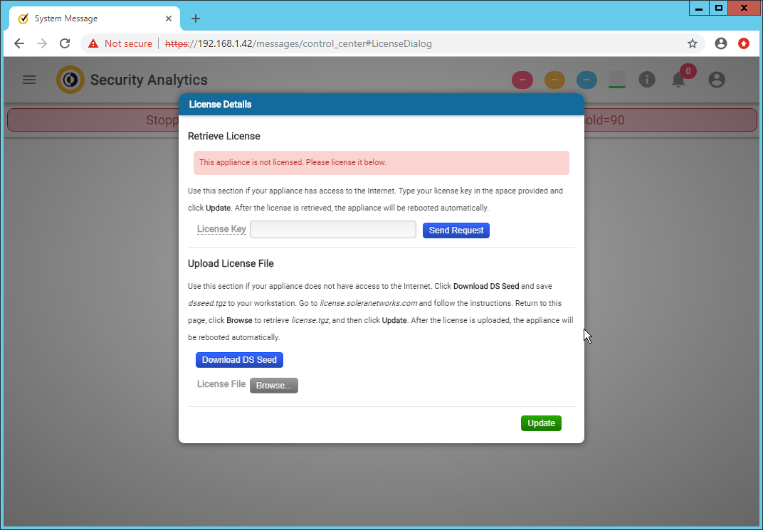
Click Update. The device will reboot.
Log in to the web page again.
Click the silhouette in the top right corner and click Account Settings.
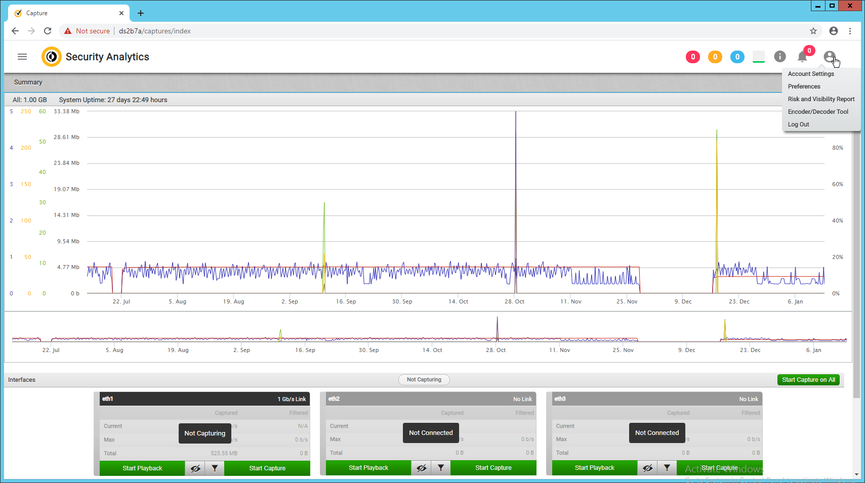
Click Change Password.
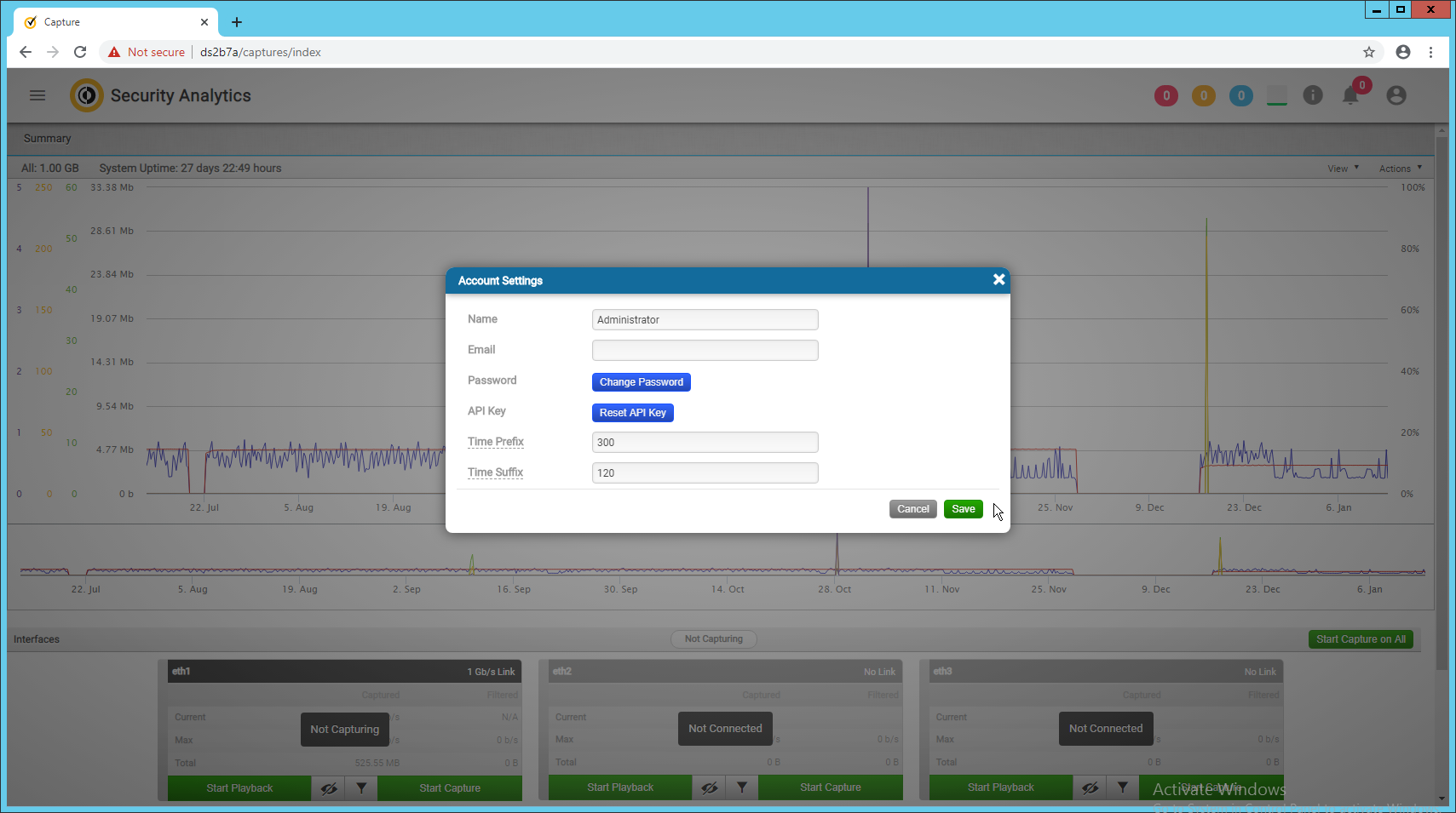
Enter a new password. Click Save.
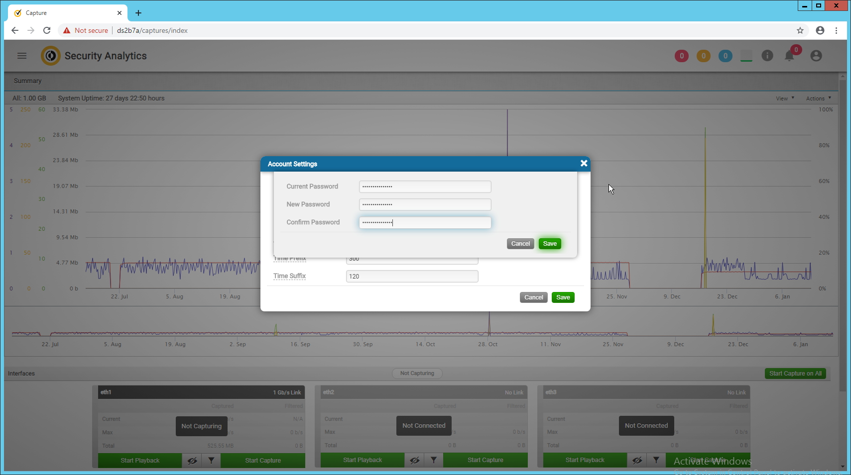
The screen should reflect that the password has been changed. Close out of both windows and return to the main web console.
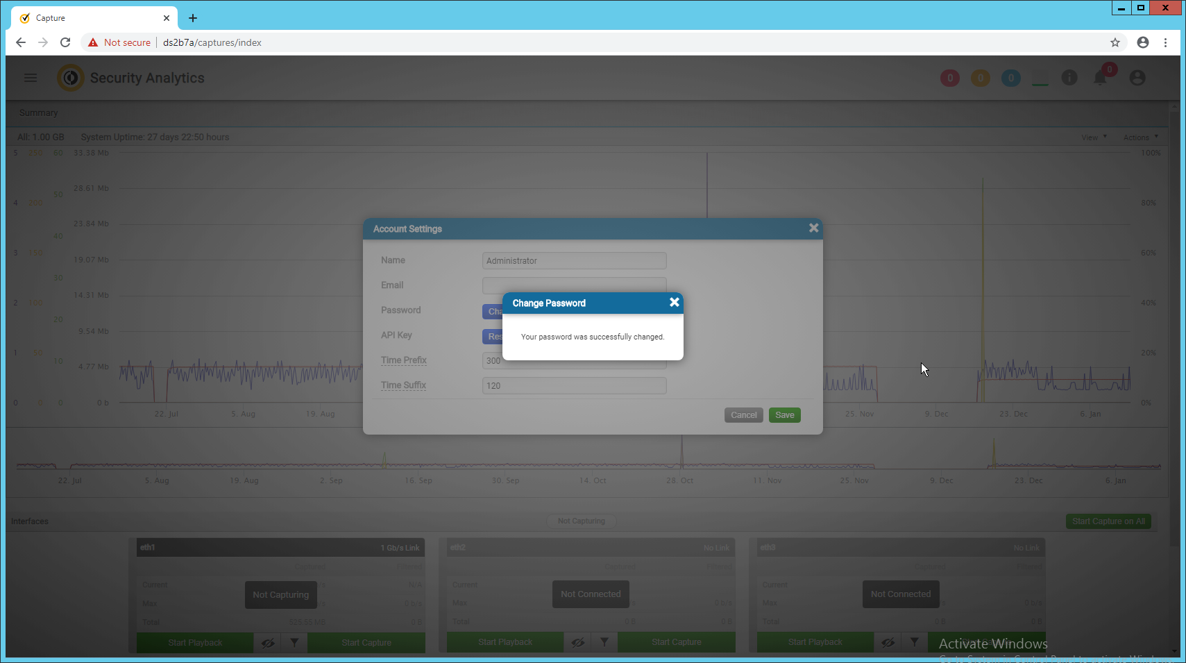
In the top left corner of the web console, click the menu button. (It shows as three horizontal bars).
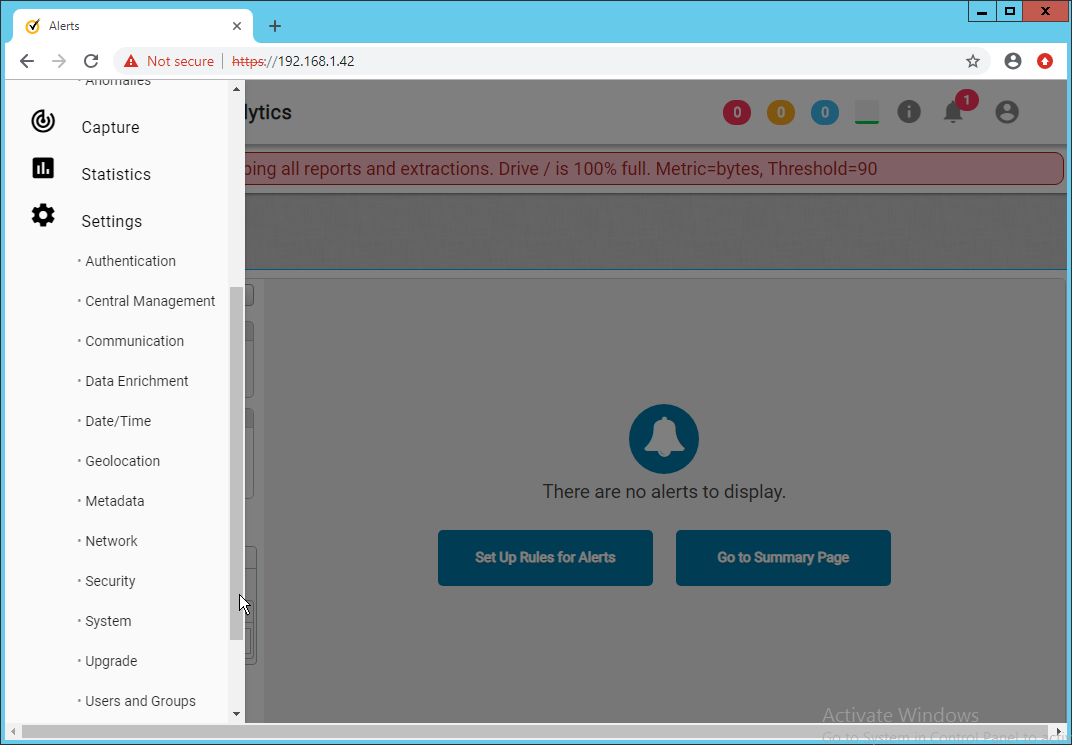
Navigate to Settings > Data Enrichment.

Click the red upside-down power symbols next to Symantec Web Reputation Service and Symantec File Reputation Service to turn them on.
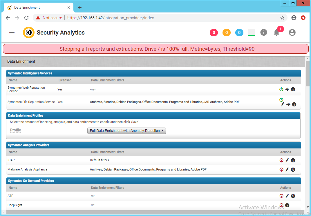
Select Full Data Enrichment (with Anomaly Protection) for the profile under Data Enrichment Profiles.
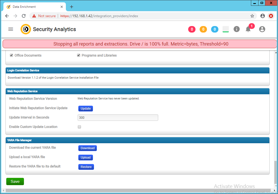
Click Save.
2.14.2 Capturing Data
Navigate to Capture > Summary in the menu.
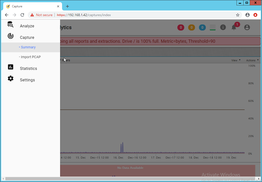
Begin capturing data on any desired interfaces by clicking Start Capture.
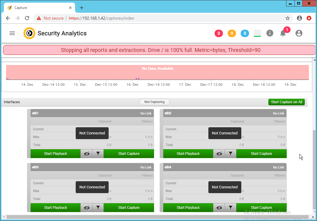
2.15 Symantec Information Centric Analytics
This section describes the installation and configuration of Symantec Information Centric Analytics (ICA).
2.15.1 Installing MS SQL 2017
Launch the SQL Setup Wizard.
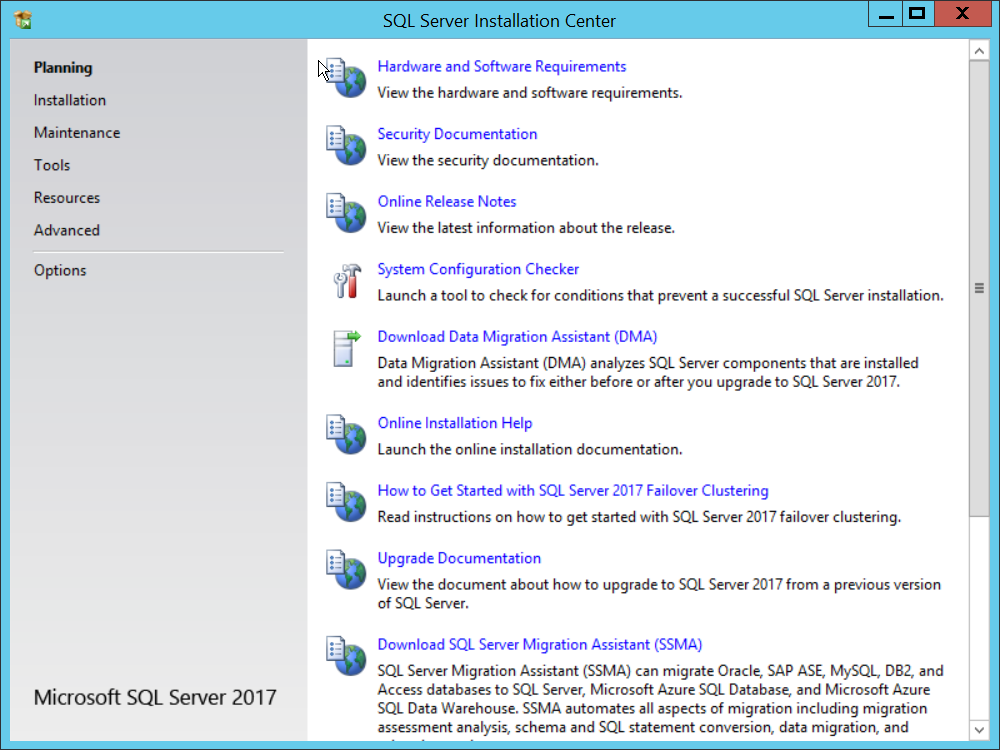
Click Installation.
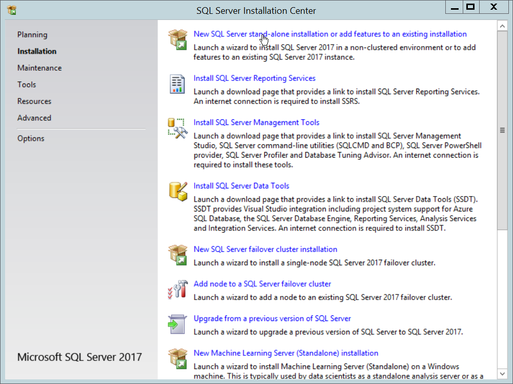
Click New SQL Server stand-alone installation or add features to an existing installation.
Enter a product key.
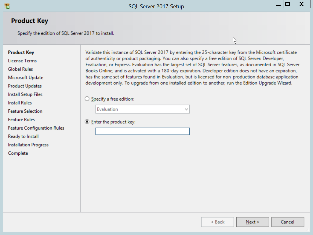
Click Next.
Check the box next to I accept the license terms.
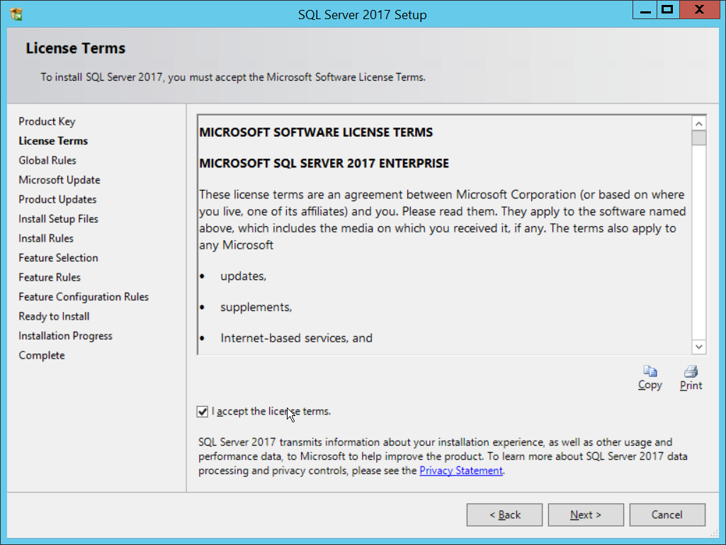
Click Next.
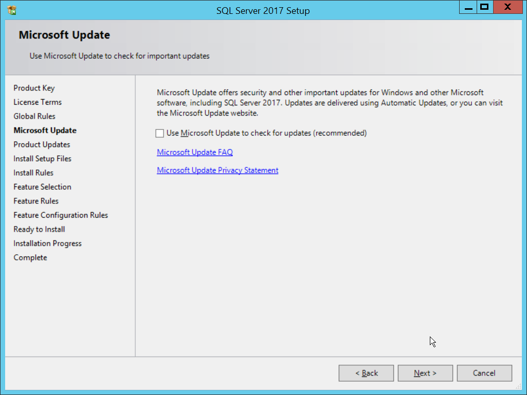
Click Next.
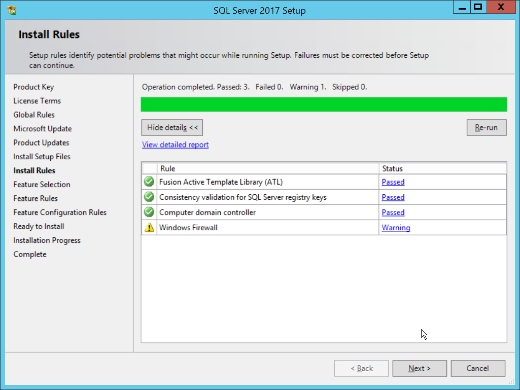
Click Next.
Ensure that box next to R and the box next to Analysis Services is checked.
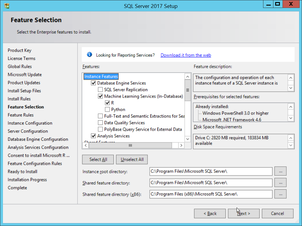
Click Next.
Select Named instance.
Specify a name for the instance.
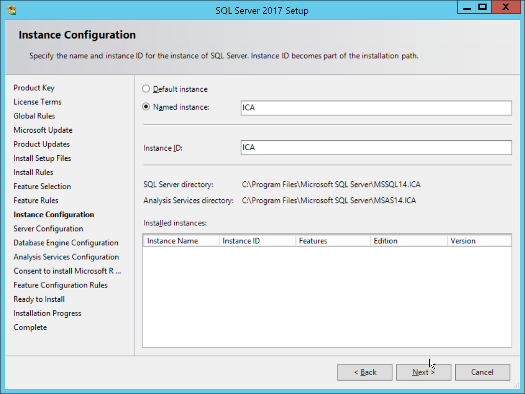
Click Next.
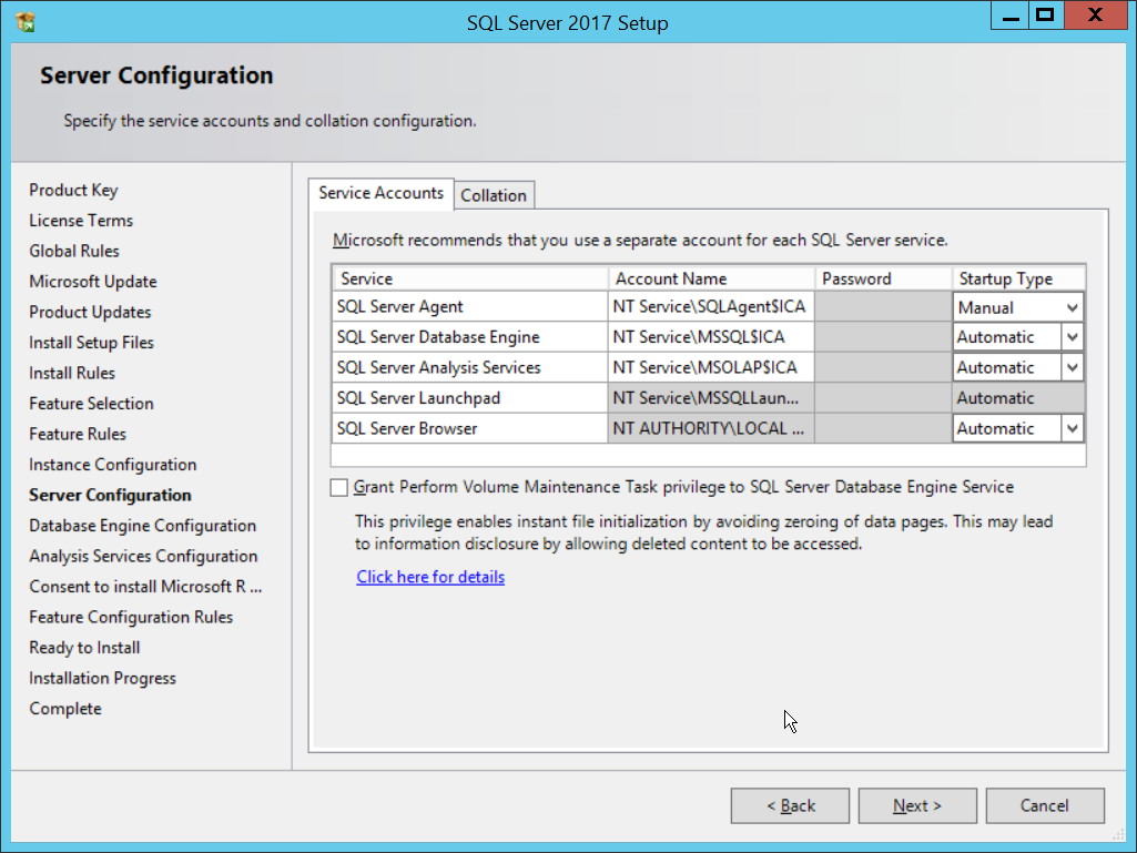
Click Next.
Select Mixed Mode (SQL Server authentication and Windows authentication).
Enter a password.
Add any users who should be administrators of the SQL database.
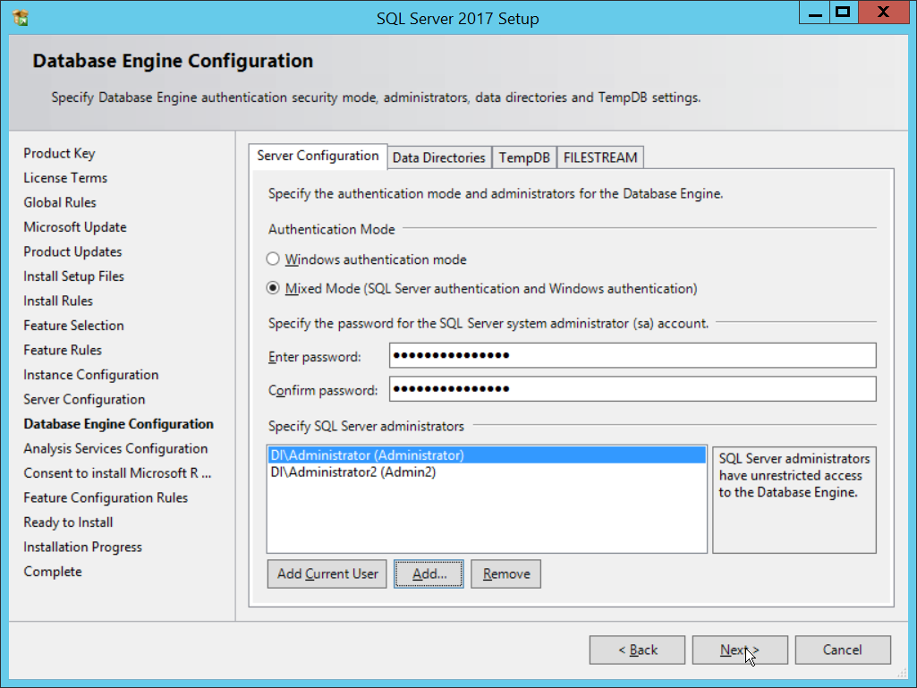
Click Next.
Select Multidimensional and Data Mining Mode.
Add any users who should be administrators of the Analysis Services.
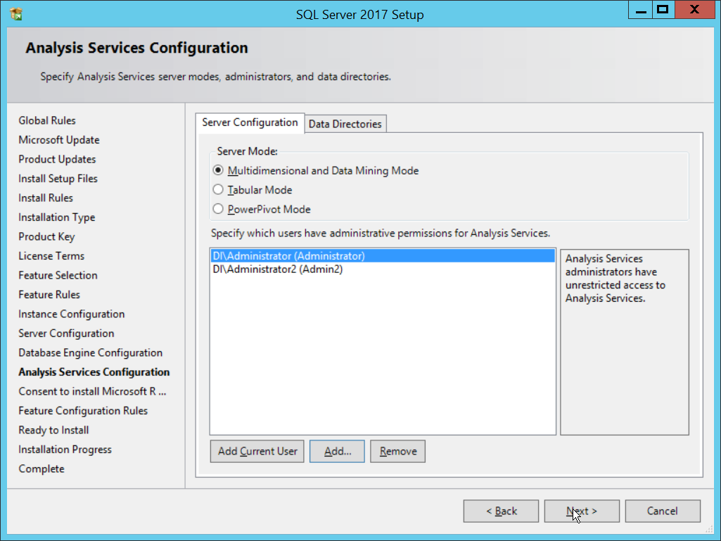
Click Next.
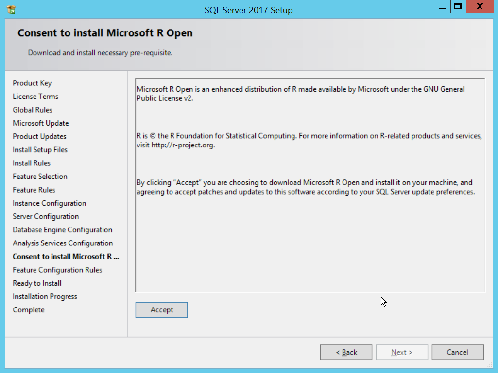
Click Accept.
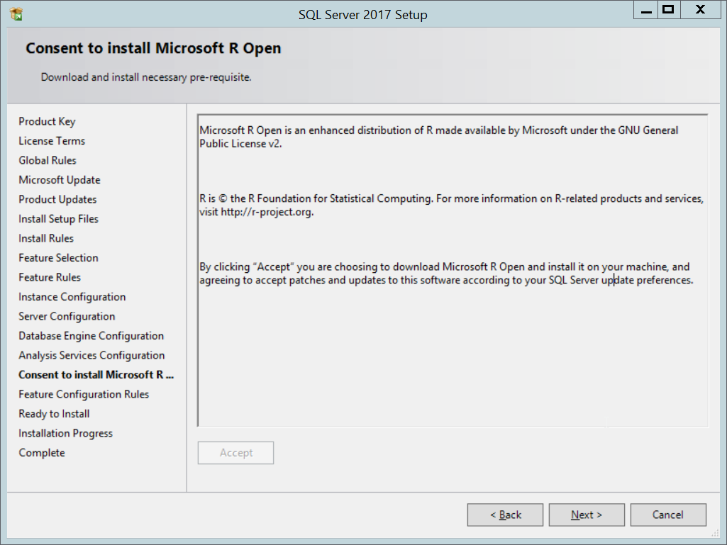
Click Next.
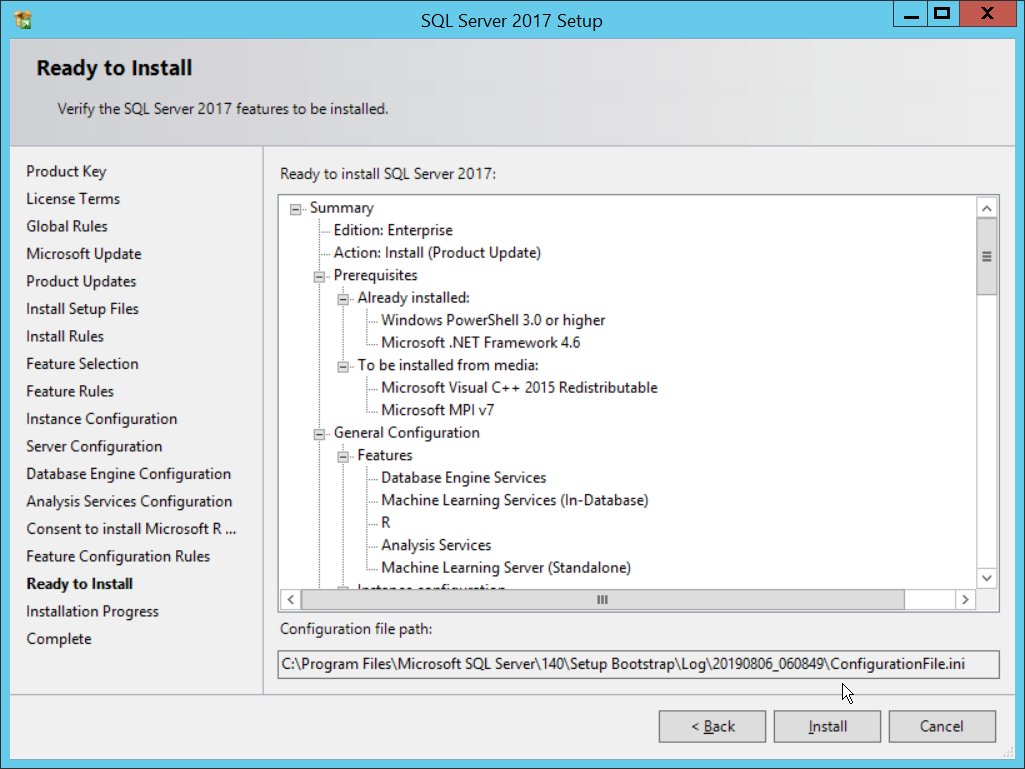
Click Install.
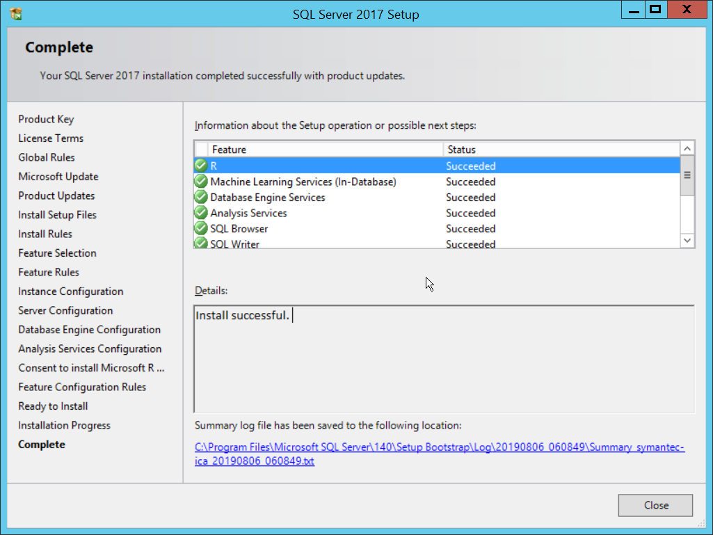
Click Close.
2.15.2 Install Windows Services
Open Server Manager.
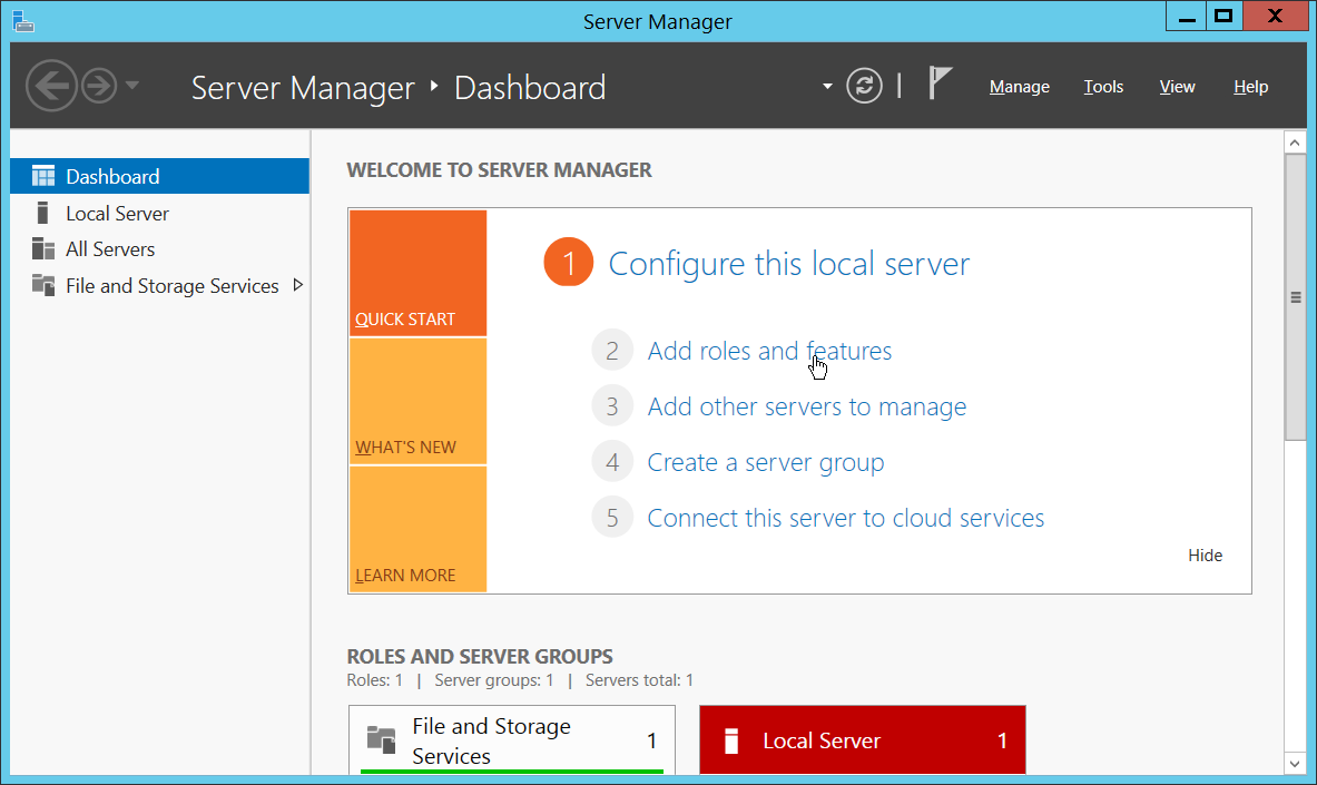
Click Add Roles and Features.
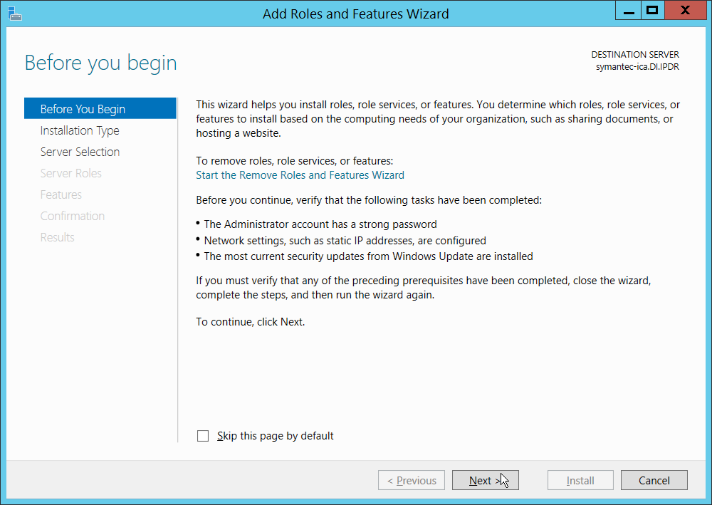
Click Next.

Click Next.
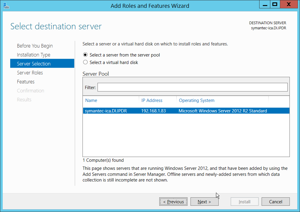
Click Next.
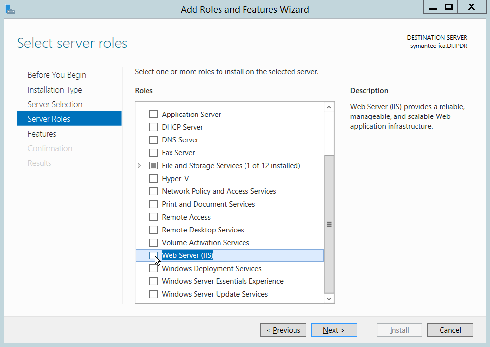
Select Web Server (IIS).
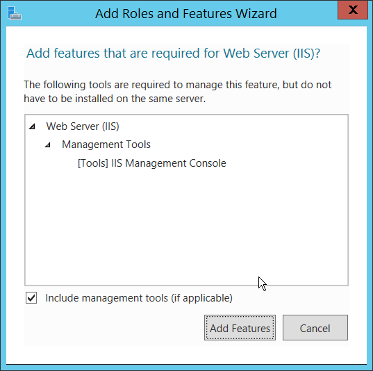
Click Add Features.
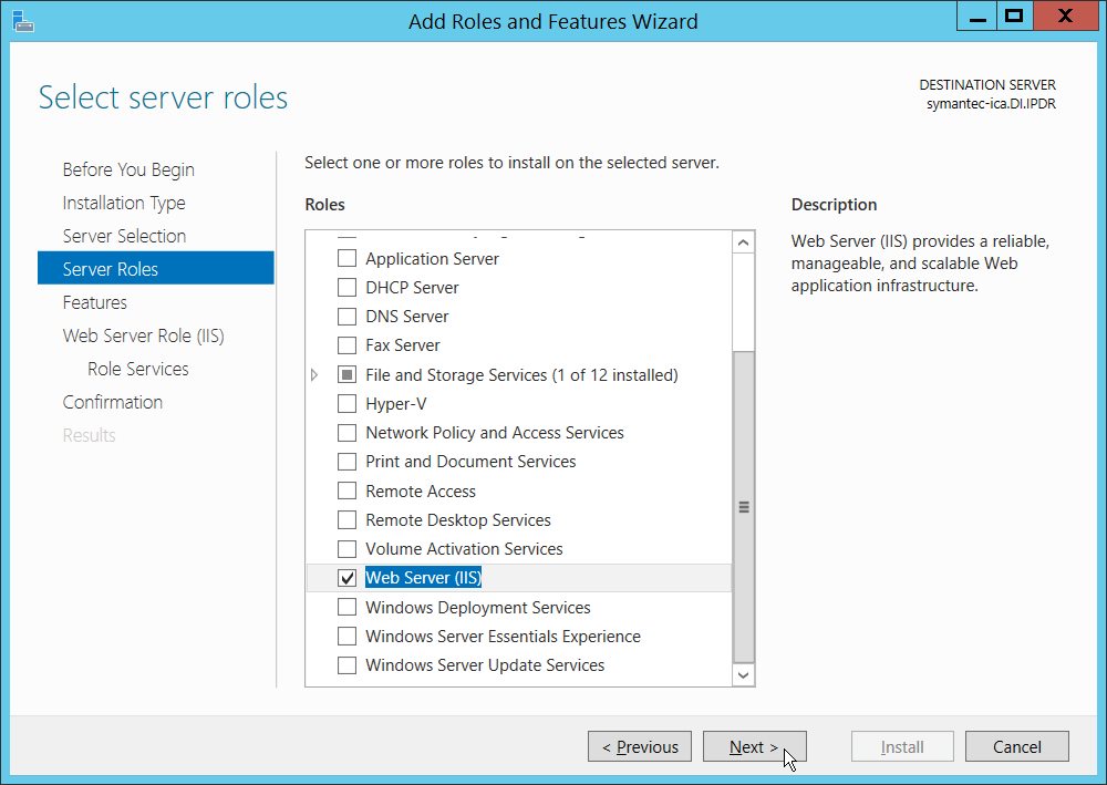
Click Next.
Select all services under .NET Framework 3.5 Features.
Select all services under .NET Framework 4.5 Features.
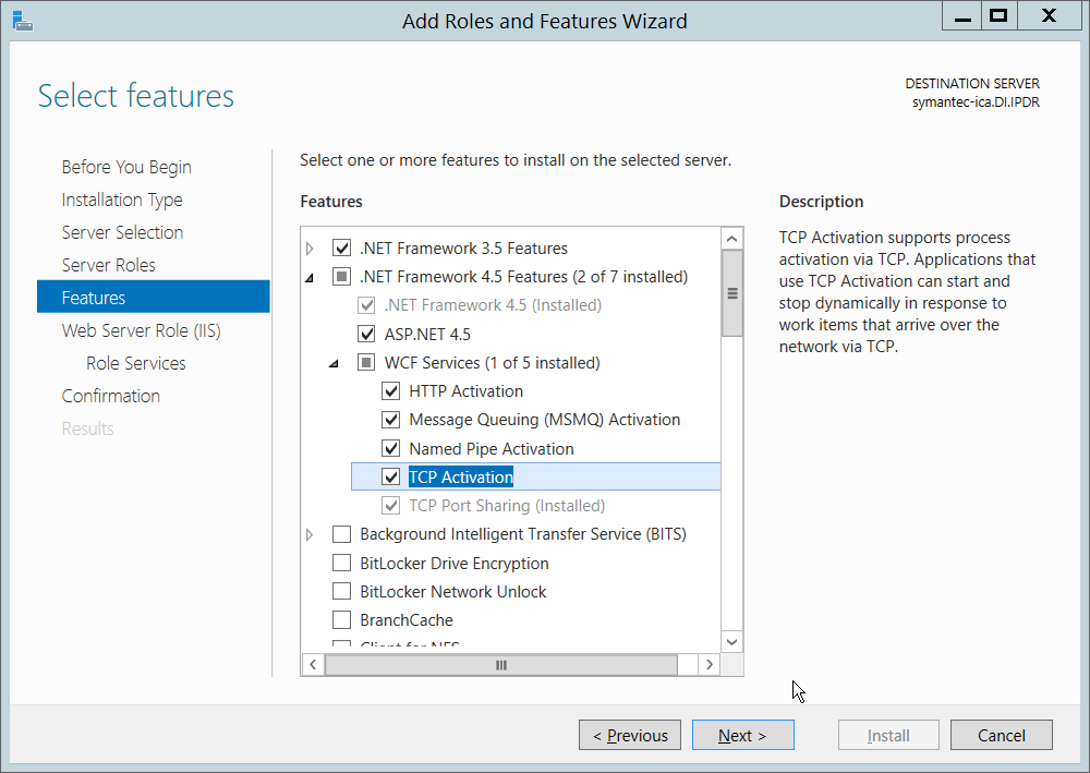
Click Next.
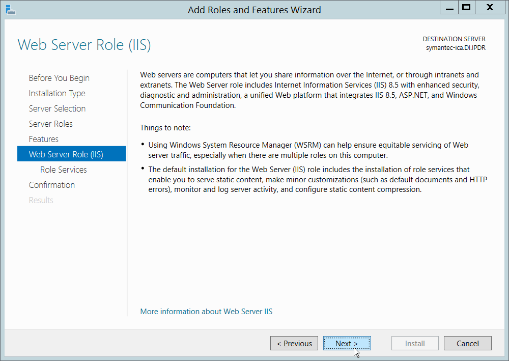
Click Next.
Ensure that the following Role Services are selected:
Common HTTP Features
Default Document
Directory Browsing
HTTP Redirection
Health and Diagnostics
HTTP Logging
Performance
Static Content Compression
Security
Windows Authentication
Application Development
.NET Extensibility 4.5
ASP.NET 4.5
ISAPI Extensions
ISAPI Filters
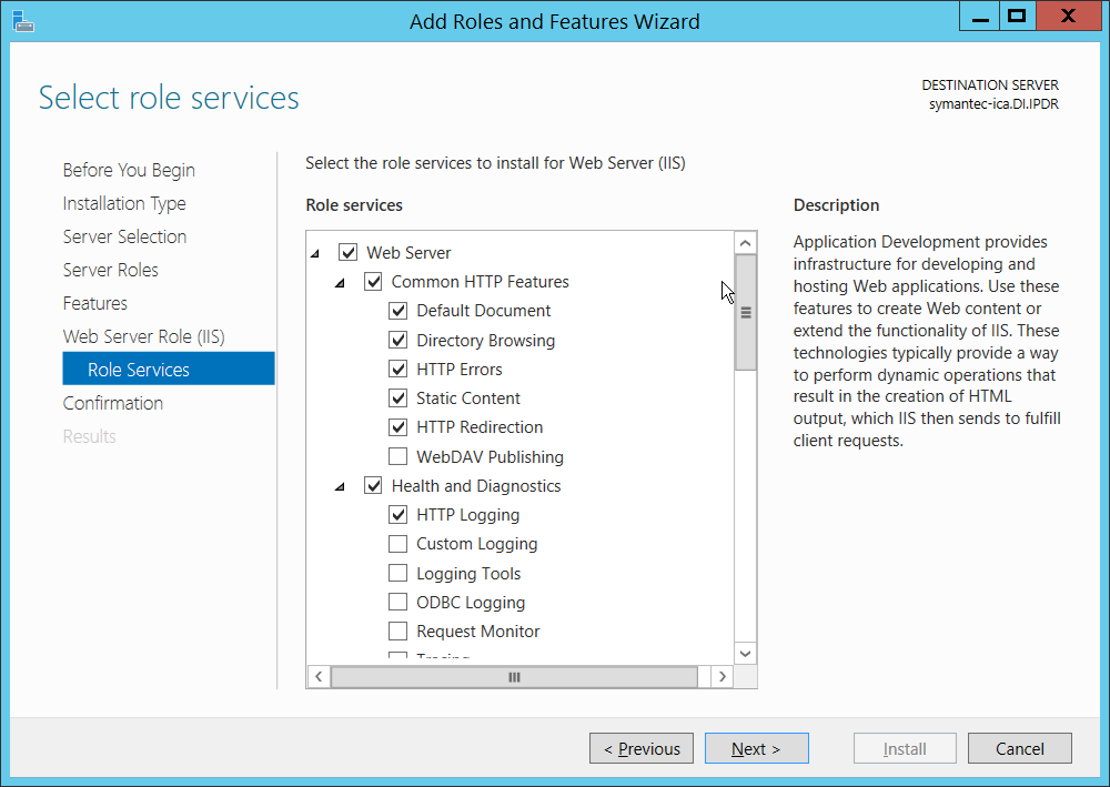
Click Next.
If necessary, specify a path to /Sources/SxS, which is found in the Windows Installation Media.
Check the box next to Restart the destination server automatically if required.
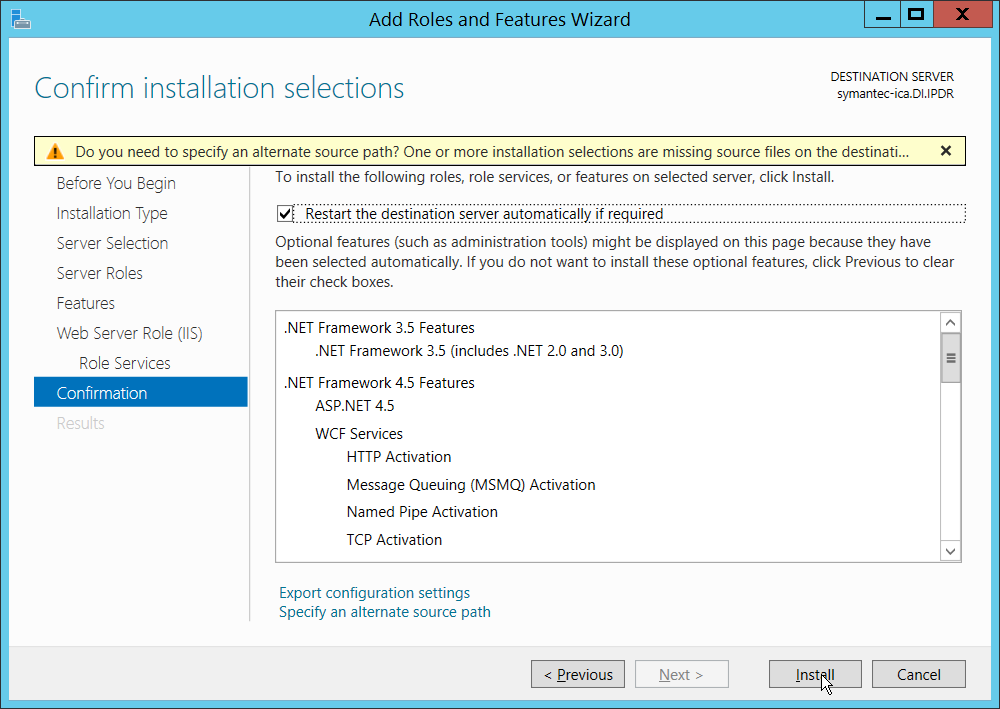
Click Install.
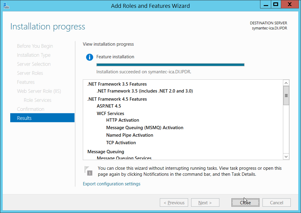
Click Close when the installation finishes.
Open Internet Information Services Manager.
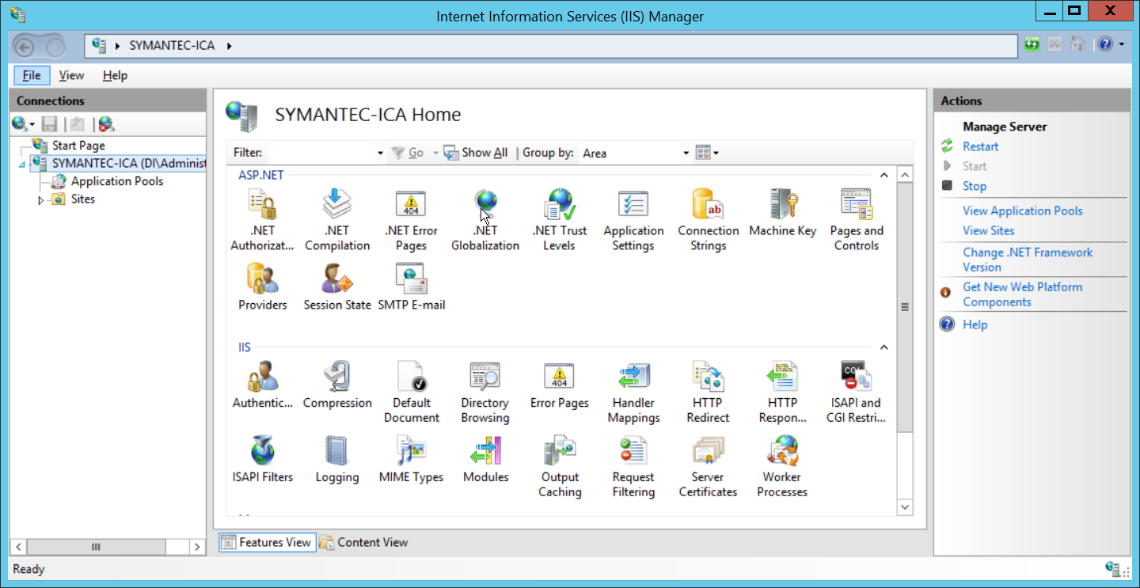
Navigate to SERVER-NAME > Sites.
Right-click the Default Web Site, and select Bindings.
Change the port for http to 8080.
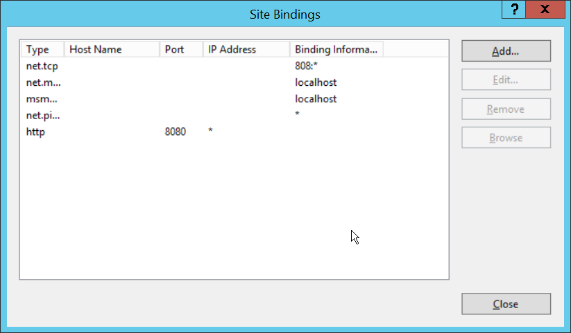
Click Close.
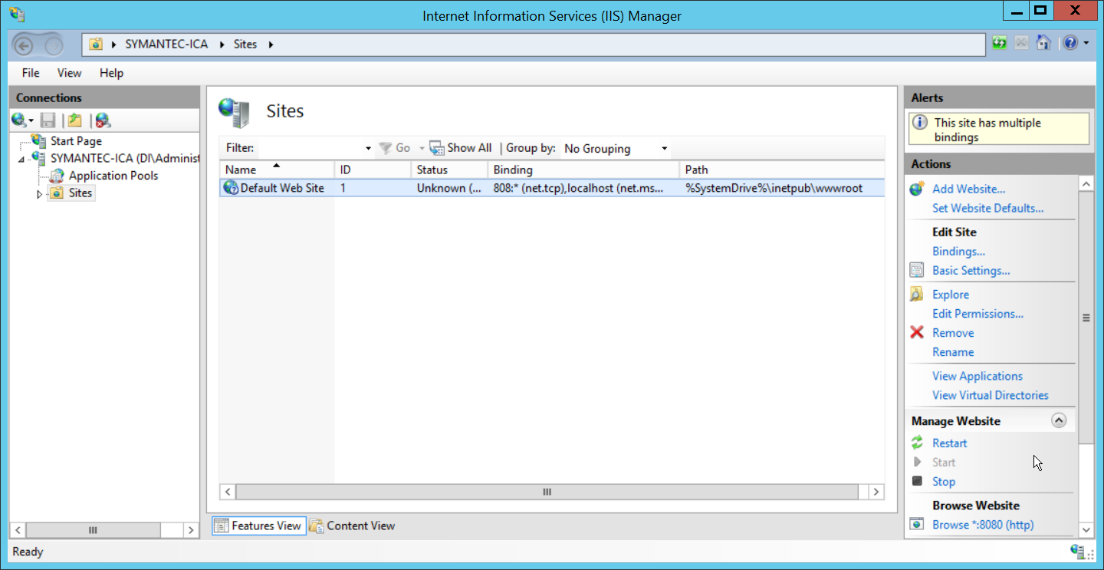
Click Restart under Manage Website.
2.15.3 Installing Symantec ICA
In Task Manager, verify that the SQL Server Agent service is running.
Copy the installation media SymantecICASoftware_65.zip onto the server.
Extract the installation media.
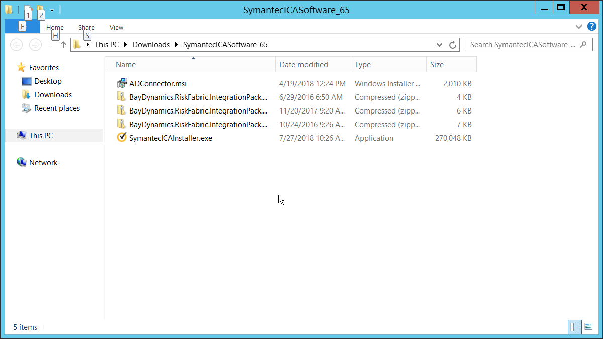
Run SymantecICAInstaller.exe.
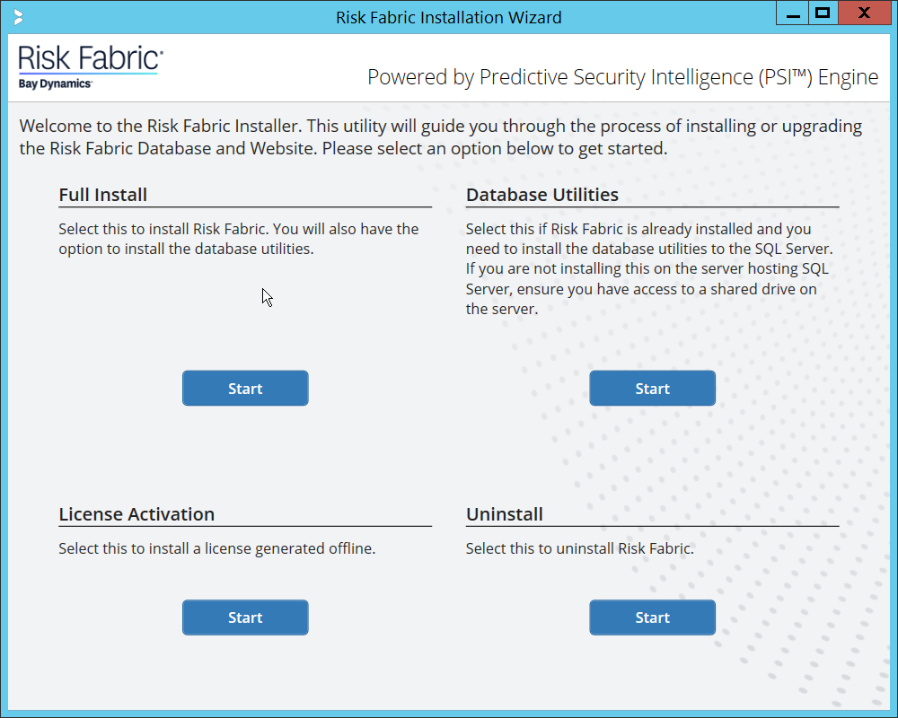
Under Full Install, click Start.
Scroll down and check the box next to I have read, understood, and agree with the terms of the license agreement.
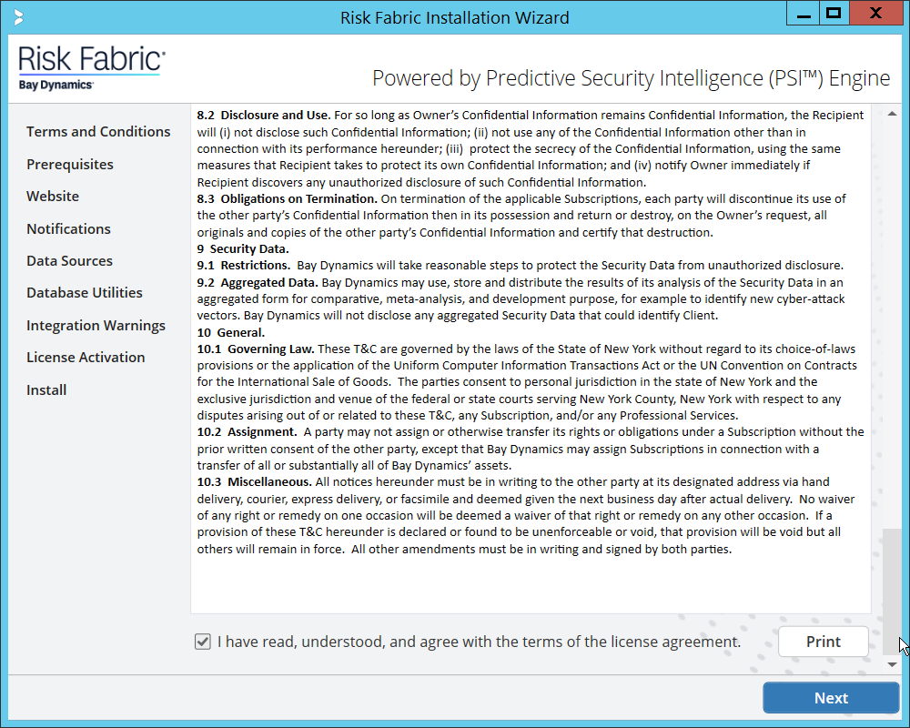
Click Next.
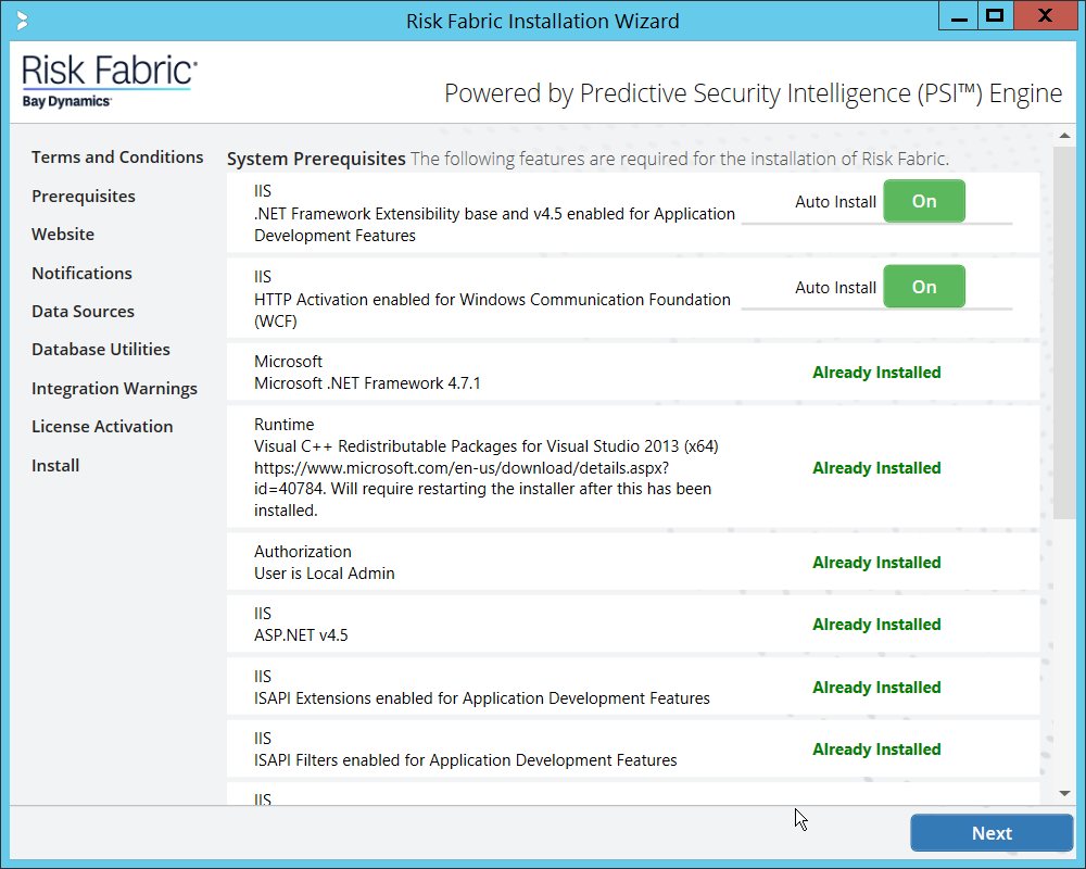
Click Next.
Enter a username and password with privileges on the domain.
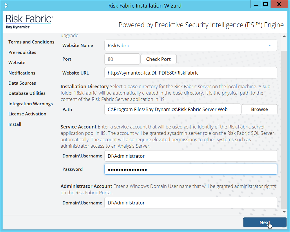
Click Next.
Configure any alert settings desired; these can be changed later.
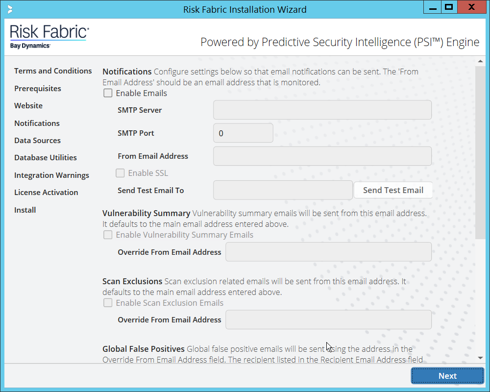
Click Next.
Enter the name of the SQL Server you created in the format <SERVER-DOMAIN-NAME>\<SQL-SERVER-NAME>.
Click Connect, and verify that there are no connection issues.
Enter the name of the SQL Analysis Services server you created in the format <SERVER-DOMAIN-NAME>\<SQL-SERVER-NAME>. (It may be the same as the SQL Server).
Click Connect, and verify that there are no connection issues.
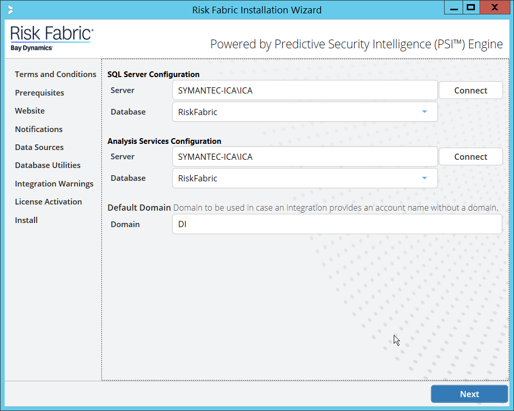
Click Next.
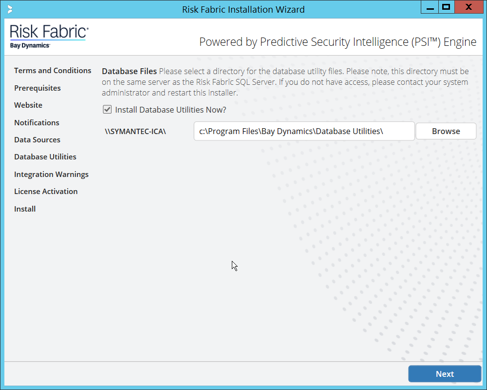
Click Next.
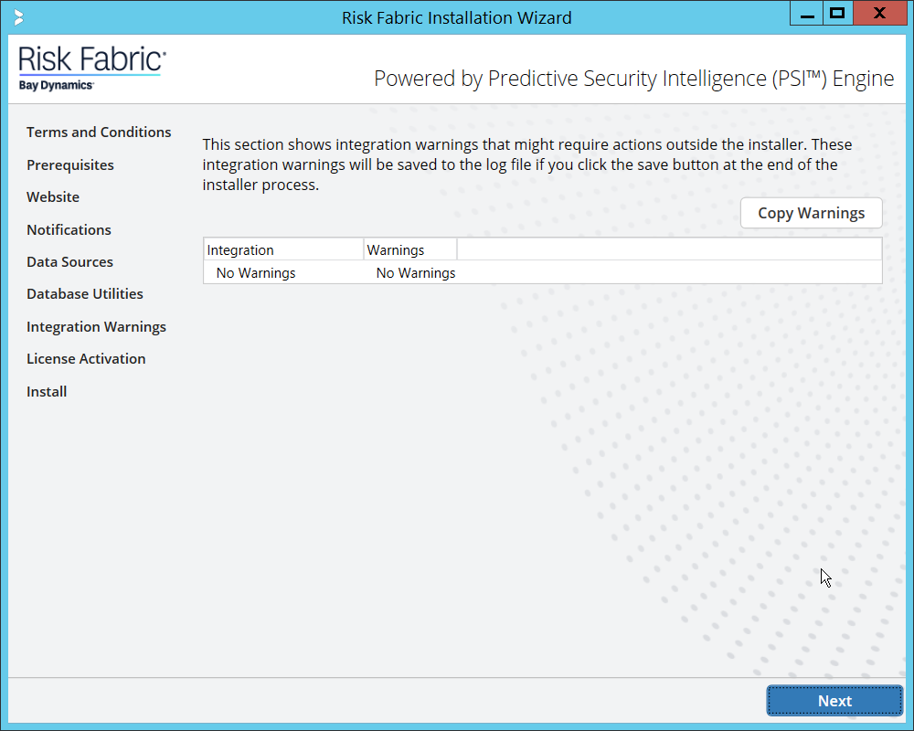
Click Next.
Check the box next to Activate Offline.
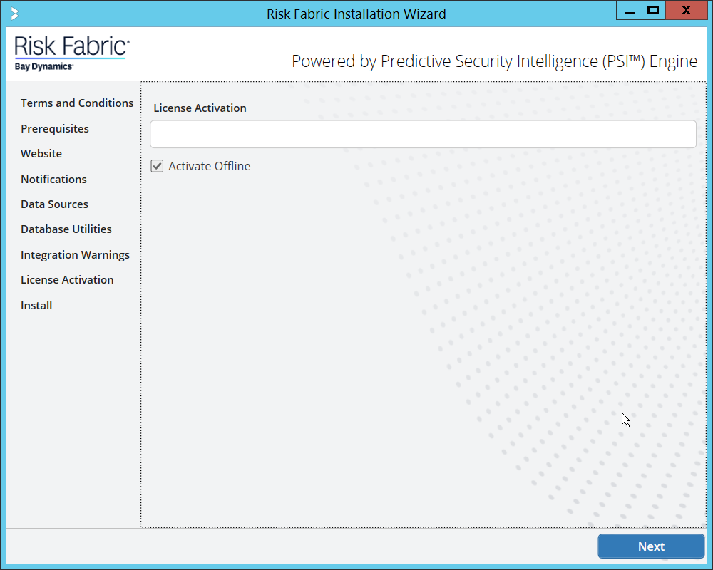
Click Next.
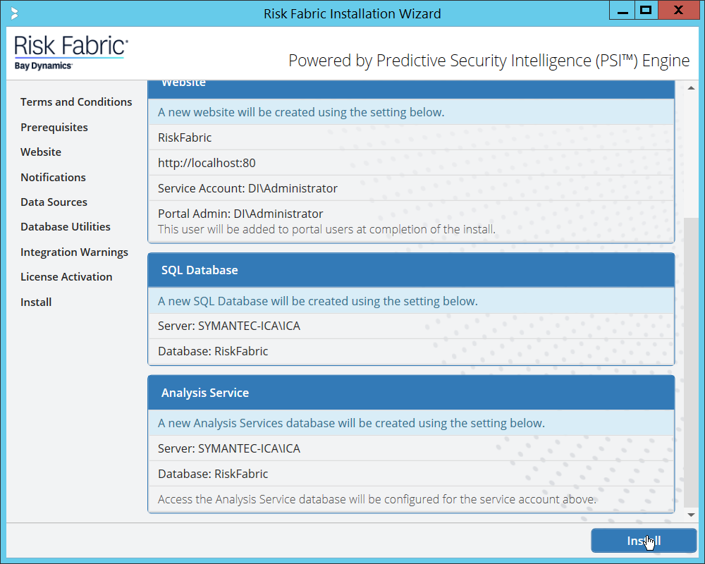
Click Install.
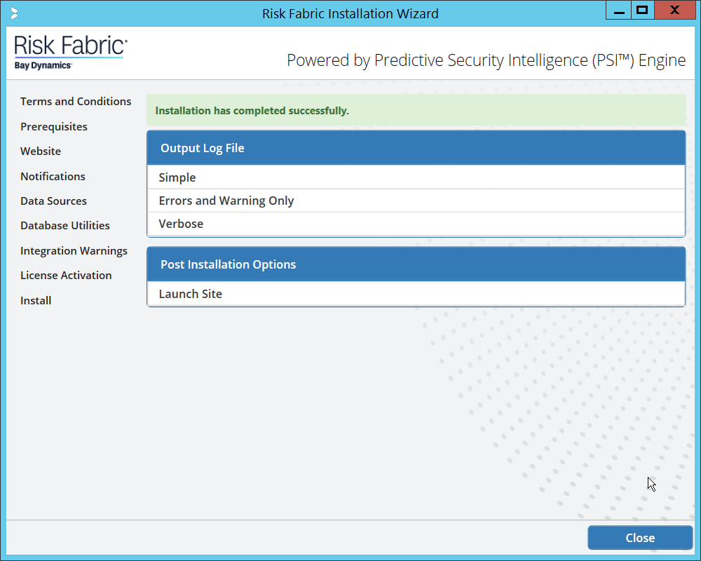
Click Close.
2.15.4 Configuring Symantec ICA for Analysis
This section will contain instructions for navigating some aspects of the ICA admin console and dashboards, though this largely depends on the specific data your organization has identified and is trying to analyze.
2.15.4.1 Installing Integration Packs
Download the relevant integration packs to someone on the local system. These are typically provided by Symantec, in a zip file. The zip file should be titled in the format of BayDynamics.RiskFabric.IntegrationPack.<productName>.
Log in to the Risk Fabric web interface.
Navigate to Admin > Integration.
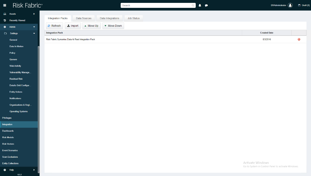
Click Import.
Find the zip file for the integration pack that you downloaded earlier.
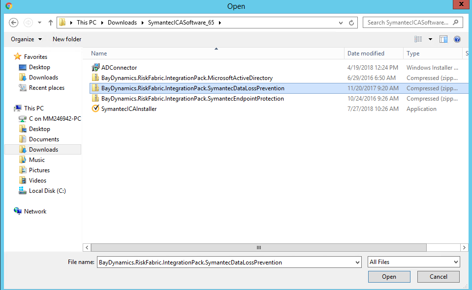
Select the file and click Open.
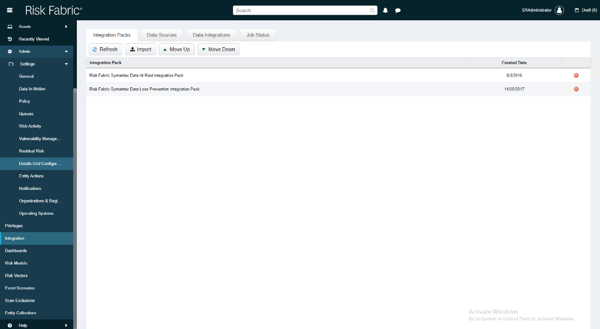
2.15.4.2 Create a View
Navigate to Analyzer > New View.
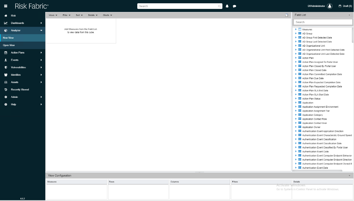
In the field list on the right, manually select or search for the data fields desired.
The fields can be added either by dragging the field onto the screen or by right-clicking on the field and selecting where it should be added. Ultimately, which views to select depends on the needs and preferences of your organization.
When finished, click Save.
Enter a name for the View Name.
Select the type of View for Type.
Check the box next to This view is accessible by all Users (Public) only if you wish for this view to be visible by anyone logged in.
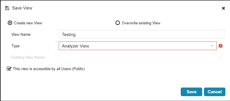
Click Save.
2.15.4.3 Open an Existing View
Navigate to Analyzer > Open View.
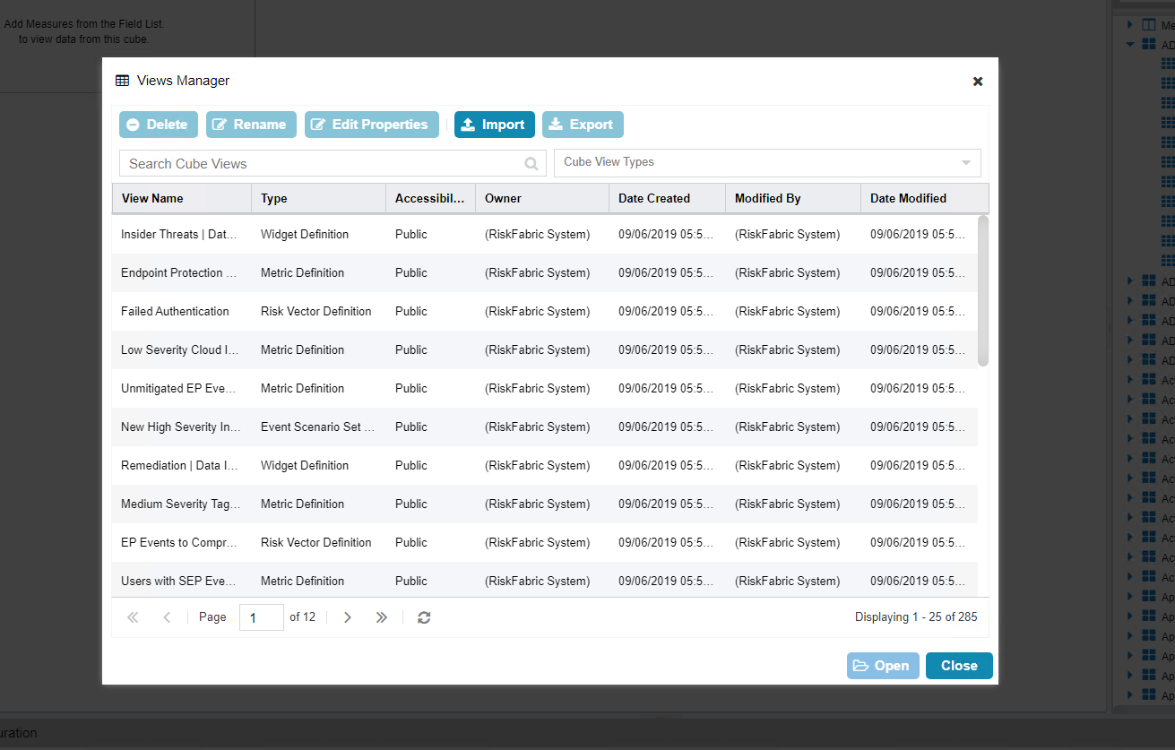
Begin to search for the view you want by typing a search term into Search Cube Views. (Note: if you created a view, it will also be present in this list).
Click the Search icon.
Select a view.
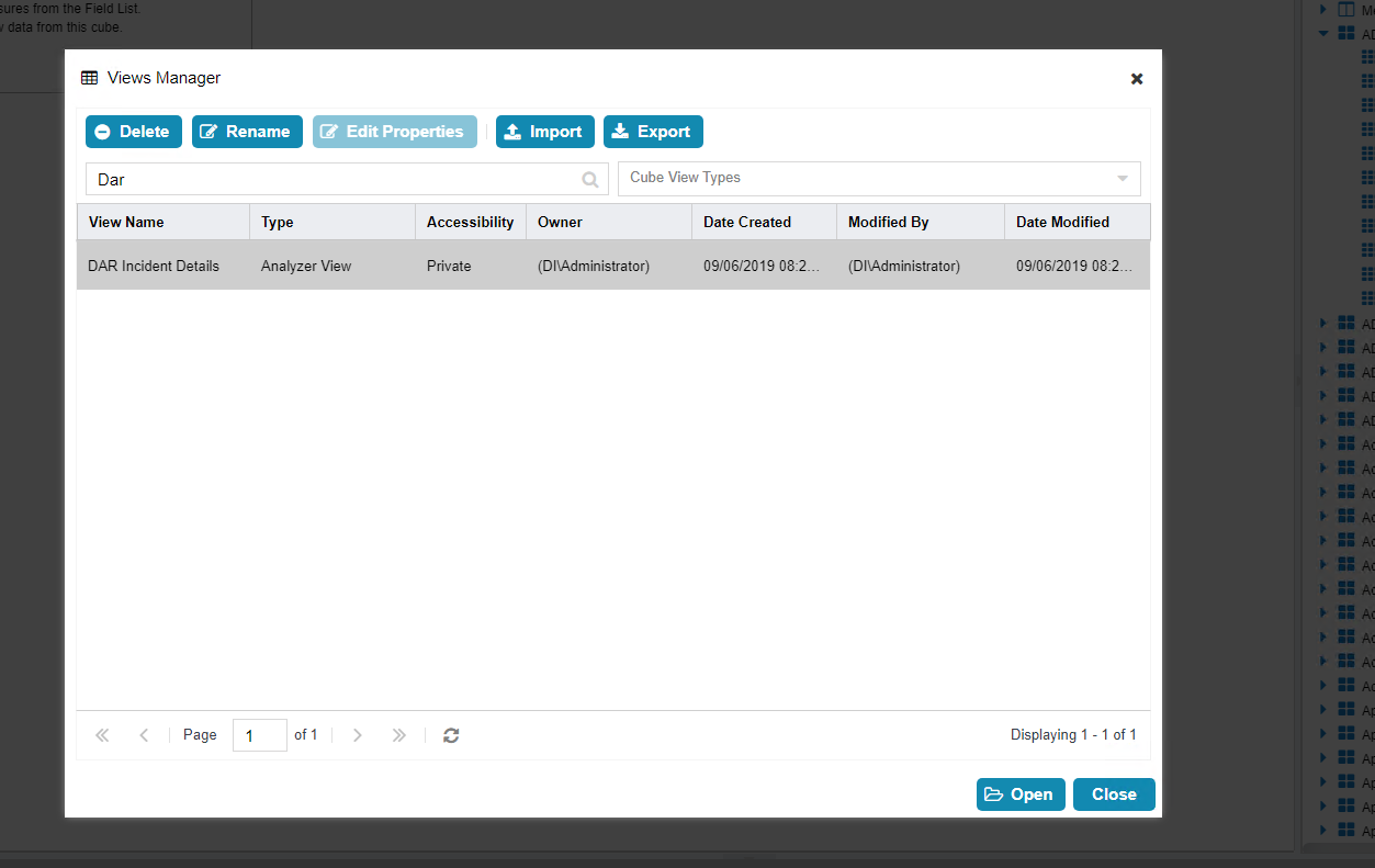
Click Open.
2.15.4.4 Viewing Detailed Analyzer Data
The desired field data can be exported to either a .csv or Microsoft Excel format, by clicking on the Export button in the details tab.
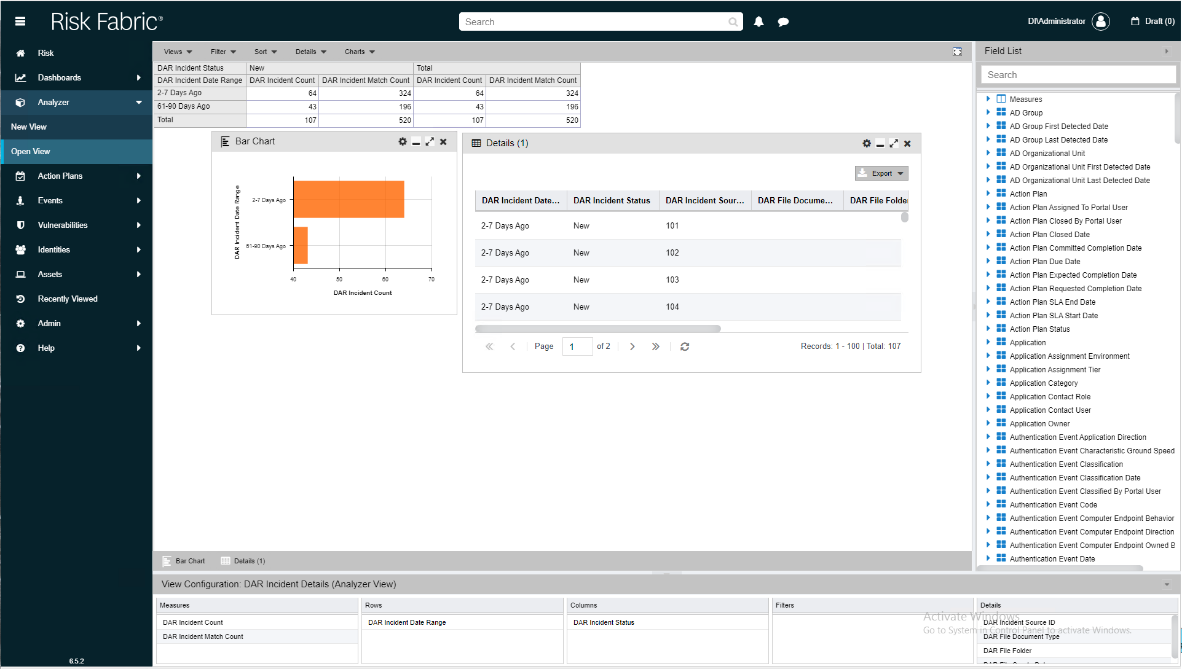
Charts can be added or removed using the Charts dropdown menu near the top of the analyzer.
Any data in the Field List on the right side can be added to or removed from the view and will be automatically incorporated into its relevant rows or columns.
The entire view format can be exported as a .json file from the Open View option.
2.16 Integration: Cisco Identity Services Engine and Cisco Stealthwatch
This section will detail an integration between Cisco Identity Services Engine (ISE) and Cisco Stealthwatch, allowing Stealthwatch to apply certain policies to hosts in ISE. Stealthwatch acts as a network monitoring solution and can be integrated with ISE to enable mitigation capabilities in response to events. Please see Deploying Cisco Stealthwatch 7.0 with Cisco ISE 2.4 using pxGrid for details and other potential uses of the integration.
2.16.1 Configuring Certificates for pxGrid
Log in to the Cisco ISE web console in a browser.
Navigate to Administration > System > Deployment.
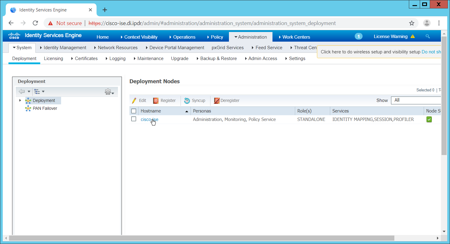
Click the hostname of the Cisco ISE machine.
Check the box next to pxGrid.
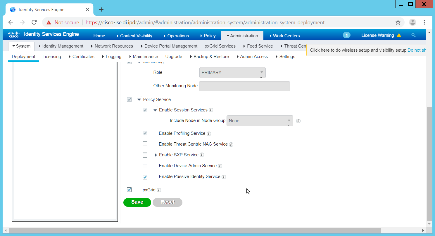
Click Save.
Navigate to Administration > pxGrid Services.
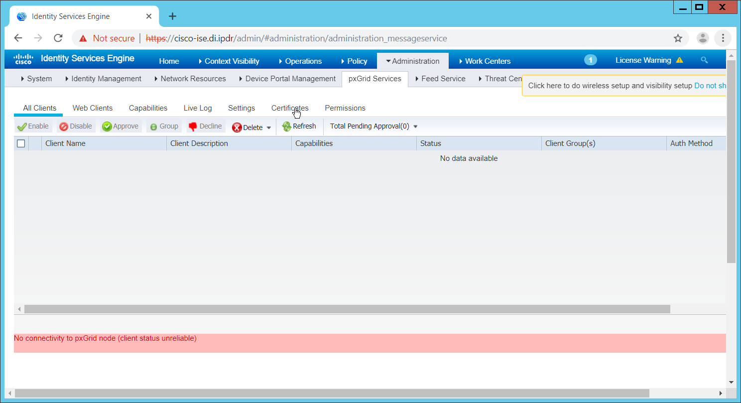
Click Certificates.
Select Download Root Certificate Chain for I want to.
Select the hostname of the Cisco ISE server for Host Names.
Select Certificate in Privacy Enhanced Electronic Mail (PEM) format, key in PLCS8 PEM format (including certificate chain) for Certificate Download Format.
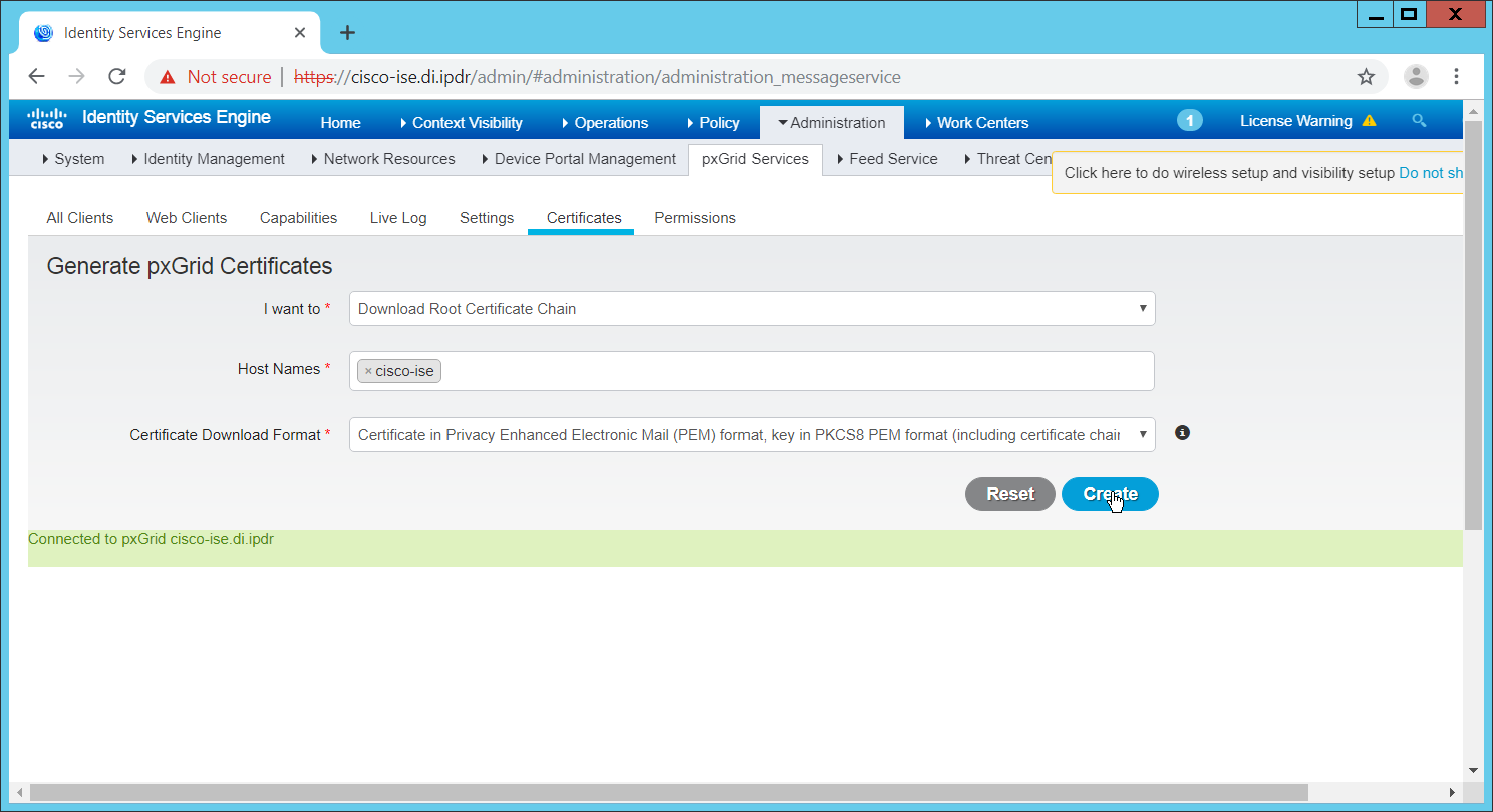
Click Create. This will download a zip file containing the certificate.
Extract the zip file—it may contain several files—the one we are interested in is the Root CA.
Log in to the Stealthwatch Management Console through the browser.
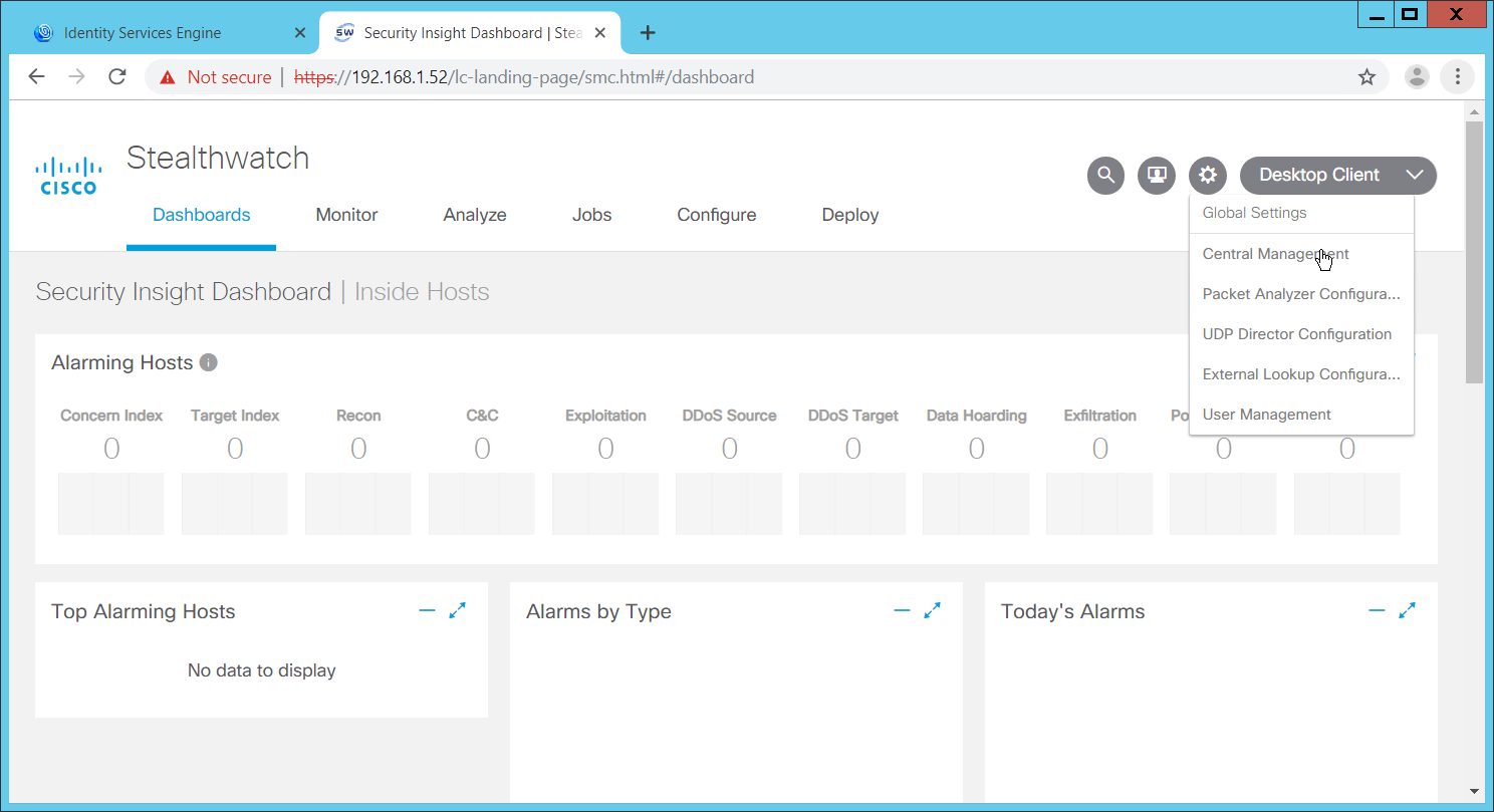
In the top right corner of the console, hover over the gear icon and select Central Management from the submenu.
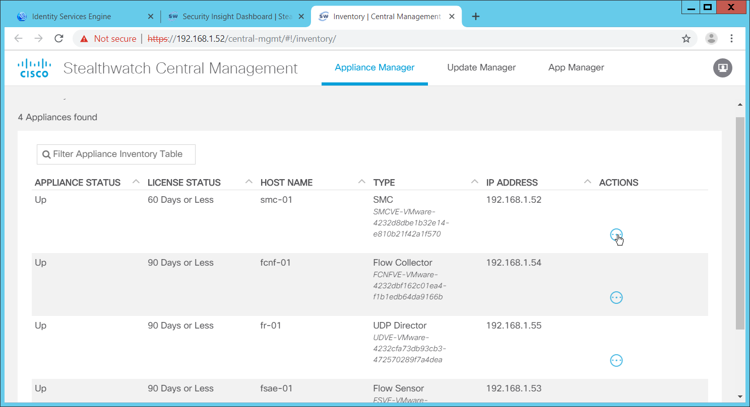
In the table, find the row with the Stealthwatch Management Console (likely labeled as SMC). Click the ellipses button in the Actions column.
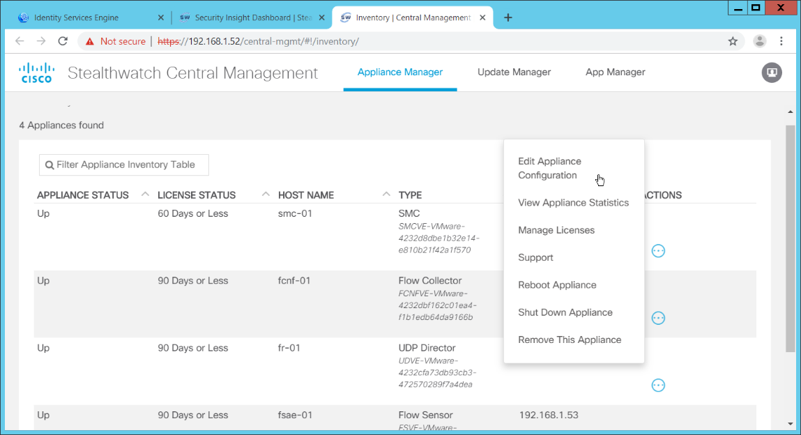
This will open a submenu. Select Edit Appliance Configurations.
Click the General tab.
Scroll down to the Trust Store section.
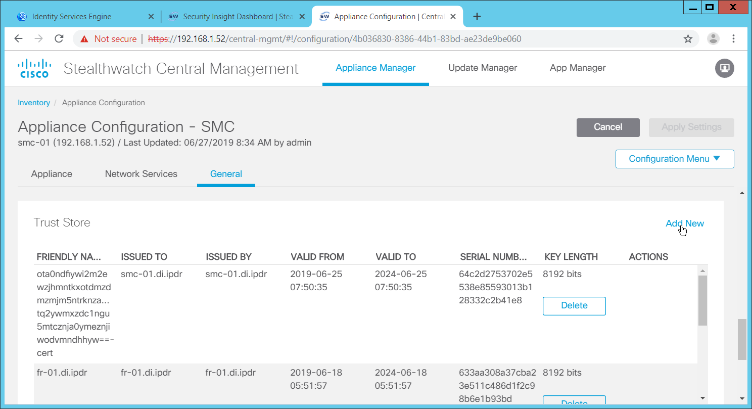
Click Add New.
Enter a name.
Click Choose File.
Select the Cisco ISE Root certificate from the files downloaded earlier.
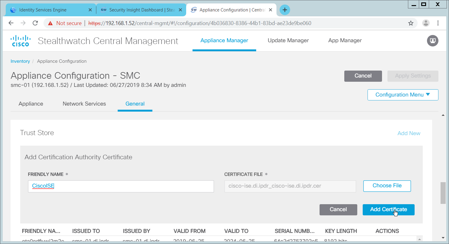
Click Add Certificate.
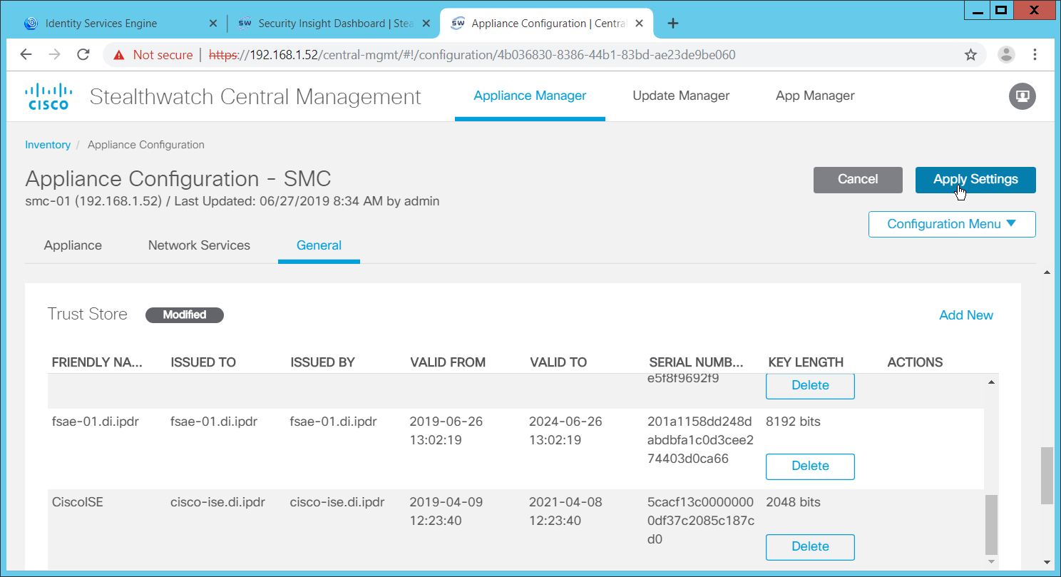
Click Apply Settings.
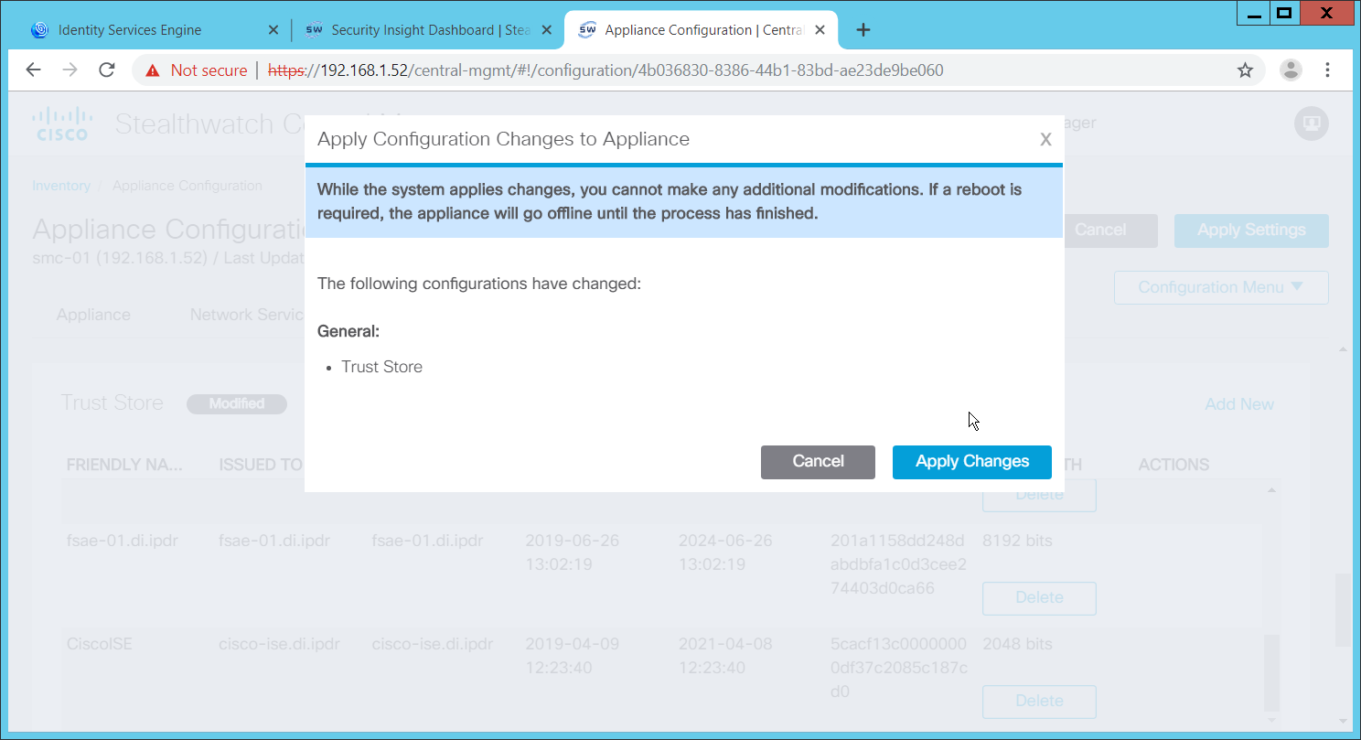
Click Apply Changes if prompted to confirm the changes.
When that finishes, navigate back to the Appliance Configurations section.
In the table, find the row with the Stealthwatch Management Console (likely labeled as SMC). Click the ellipses button in the Actions column.
This will open a submenu. Select Edit Appliance Configurations.
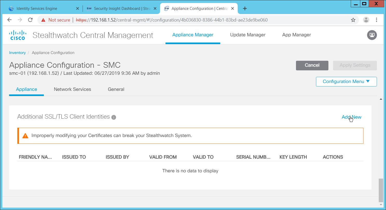
Click Add New under Additional SSL/TLS Client Identities.
Select 2048 for RSA Key Length.
Enter your organization’s information.
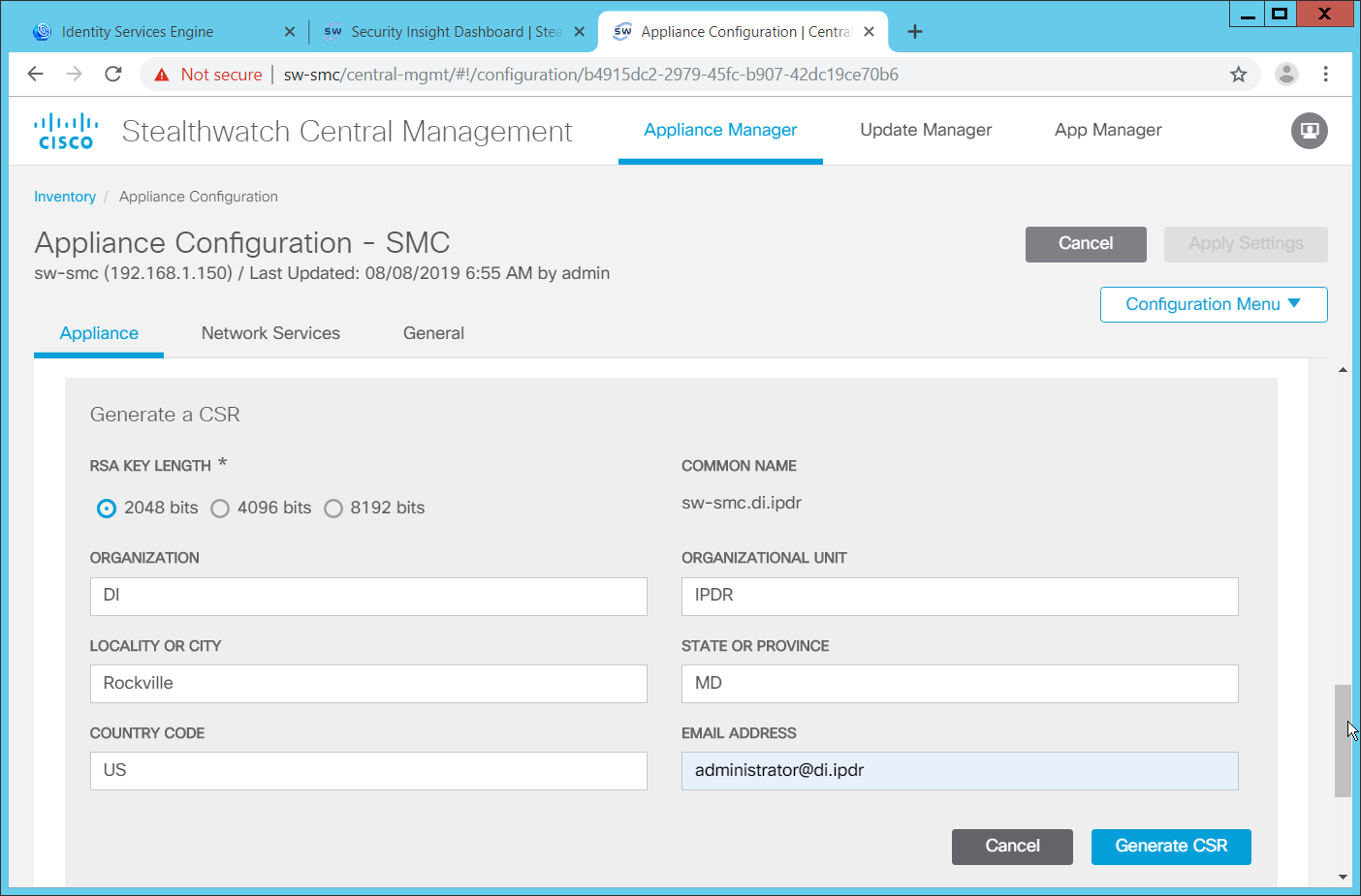
Click Generate CSR.
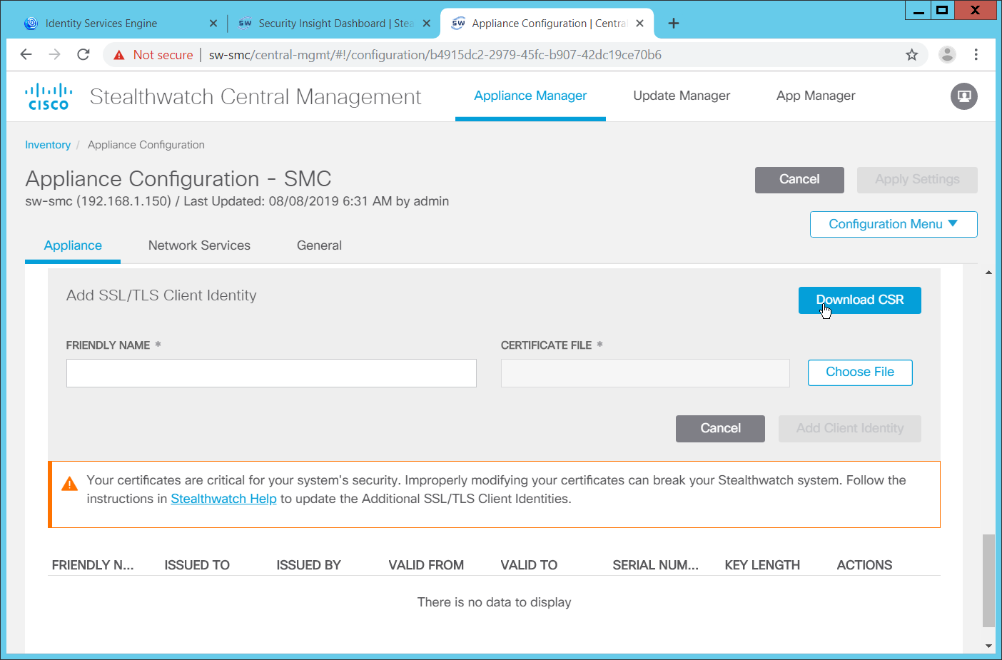
When this finishes, click Download CSR.
Open the Certificate Signing Request (CSR) in a text file, and copy all the contents.
On the ISE web console, navigate to Administration > pxGrid Services > Certificates > Generate pxGrid Certificates.
Select Generate a single certificate (with certificate signing request) for I want to.
Paste the copied text into the Certificate Signing Request Details.
Enter a description such as SMC for the Description.
Select IP Address for Subject Alternative Name (SAN).
Enter the IP Address of the Stealthwatch Management Console.
Select PKCS12 format (including certificate chain; one file for both the certificate chain and key) for Certificate Download Format.
Enter a password, and confirm the password.
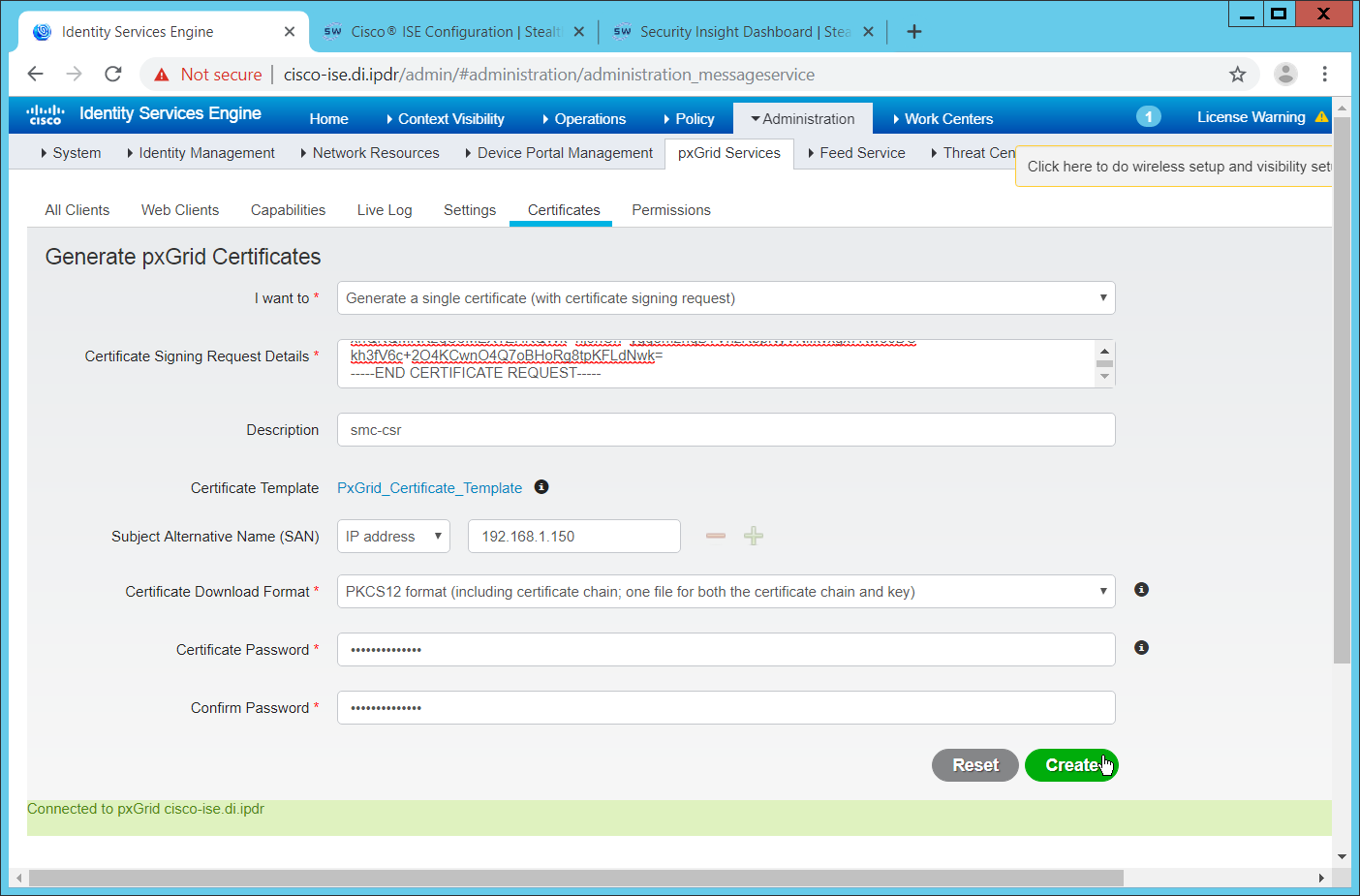
Click Create.
This will download a zip file. Unzip the file.
On the Stealthwatch Management Console (SMC) web console, under Additional SSL/TLS Client Identities (where you downloaded the CSR), click Choose File.
Upload the certificate file from the zip file that has the hostname of the SMC in it; the file extension should be .p12.
Enter a name for Friendly Name.
Enter the password used in ISE when generating the certificate.
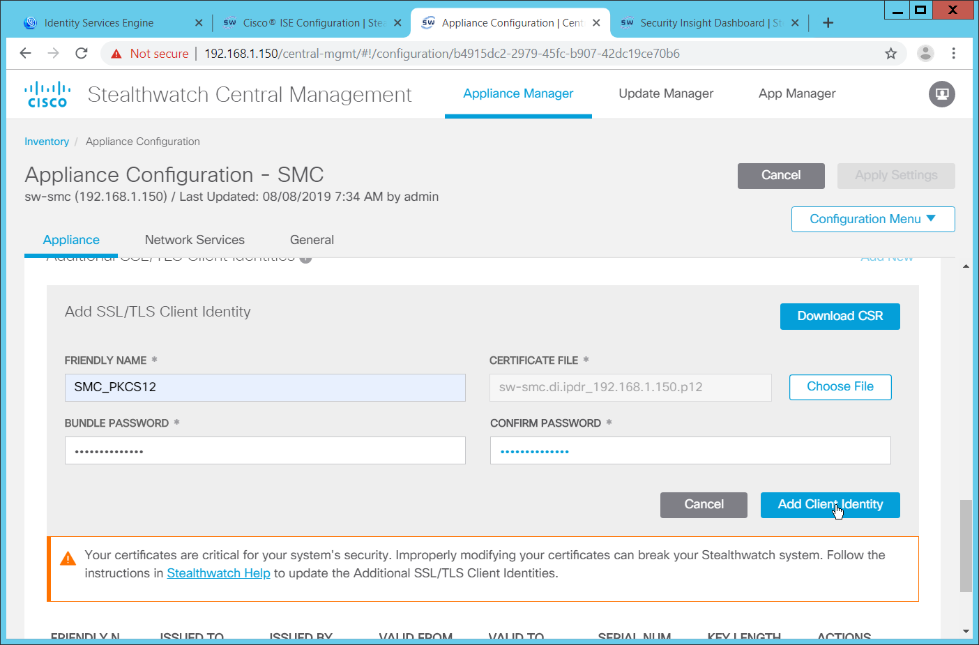
Click Add Client Identity.
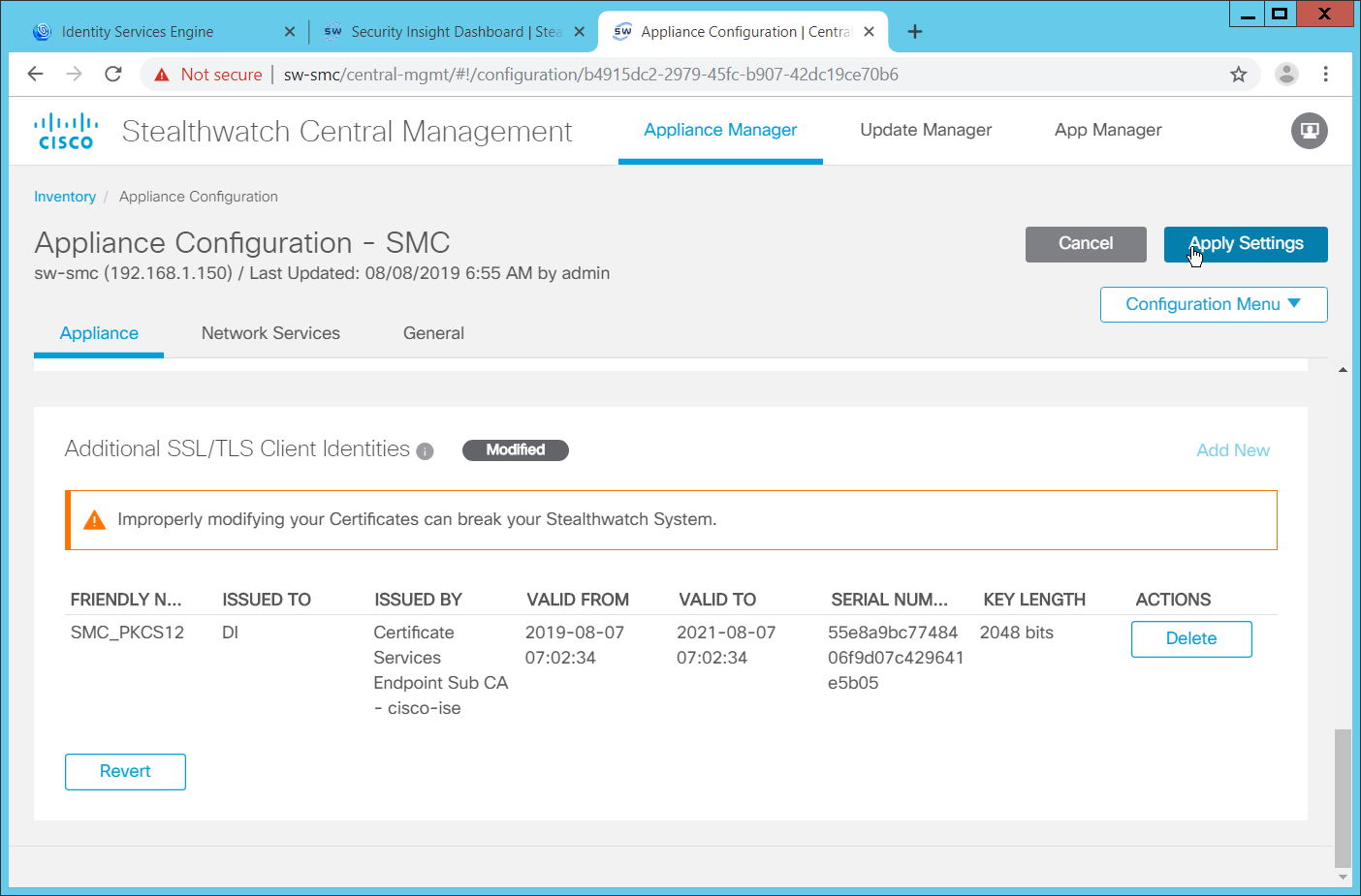
Click Apply Settings.
Navigate back to the SMC web console home screen.
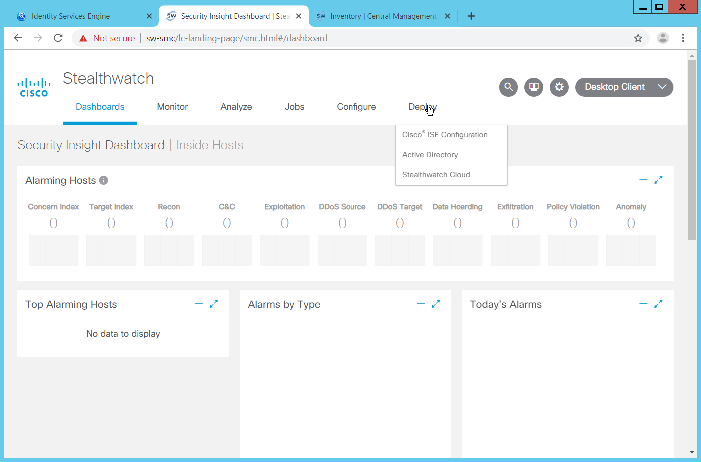
Navigate to Deploy > Cisco ISE Configuration.
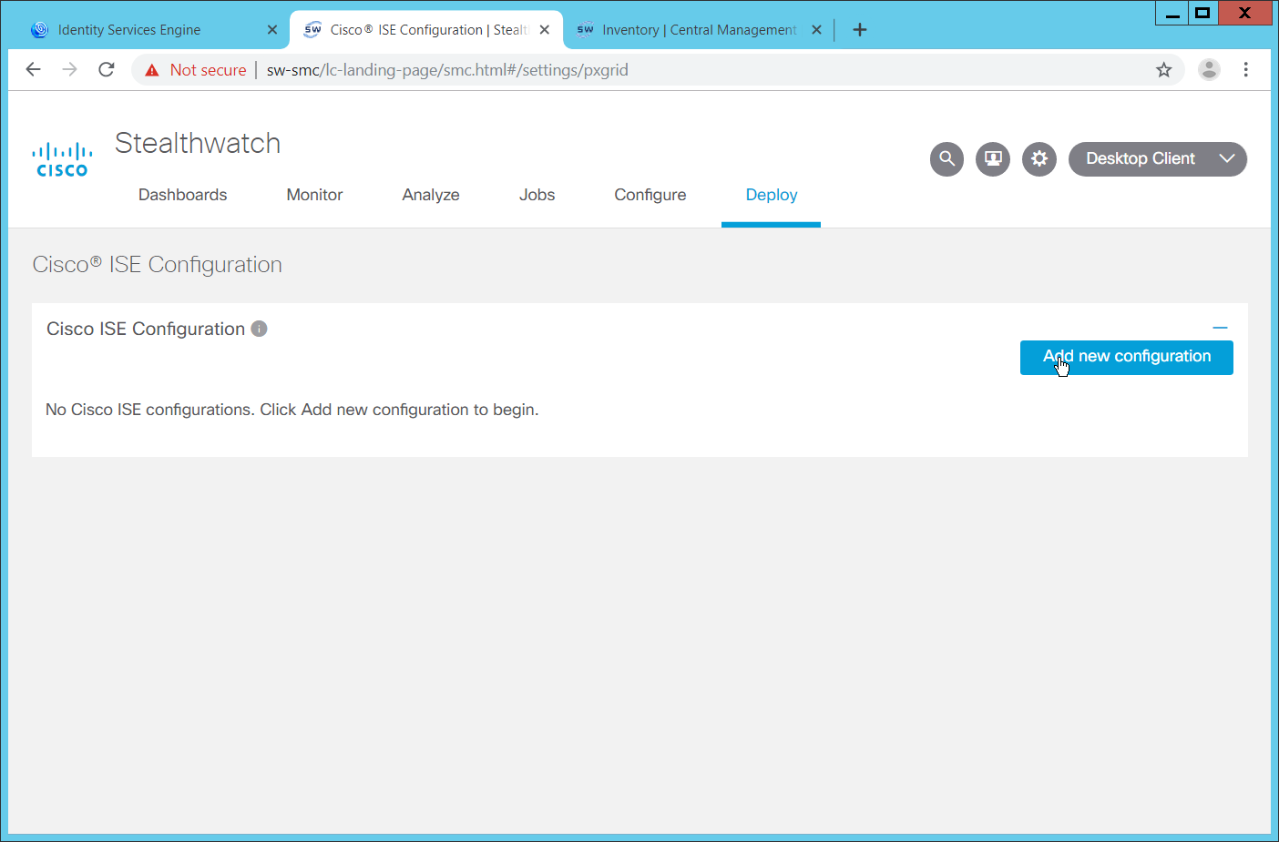
Click Add New Configuration.
Enter a Cisco ISE cluster name.
Select the certificate you just uploaded for Certificate.
Enter the IP Address of Cisco ISE for Primary pxGrid Node.
Enter a username for the SMC to use.
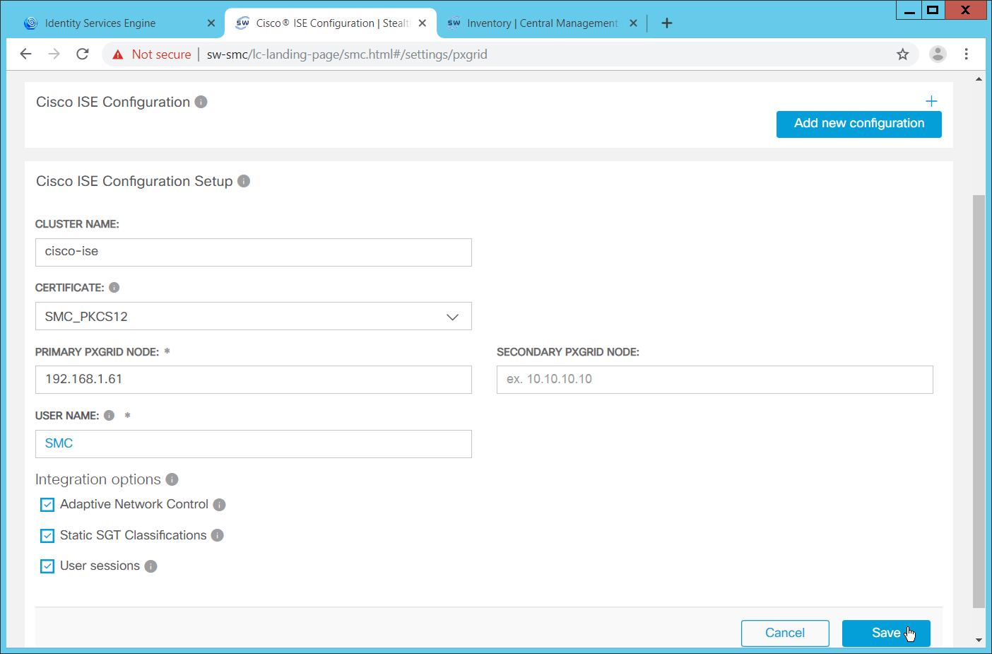
Click Save.
On the Cisco ISE web portal, navigate to Administration > pxGrid Services > All Clients.
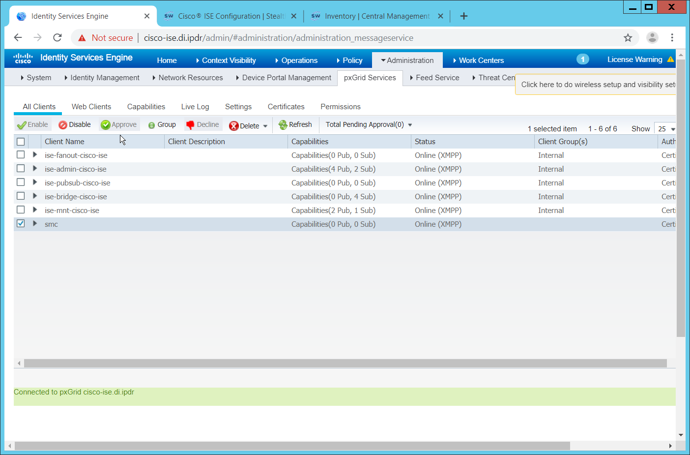
If the SMC client you just created says Pending, check the box next to it and click Approve.
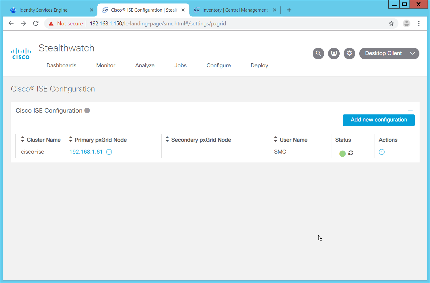
The SMC Cisco ISE Configuration page will have a green status icon if it can successfully authenticate to ISE.
2.16.2 Configuring Stealthwatch to Quarantine through ISE
Navigate to Operations > Adaptive Network Control > Policy List.
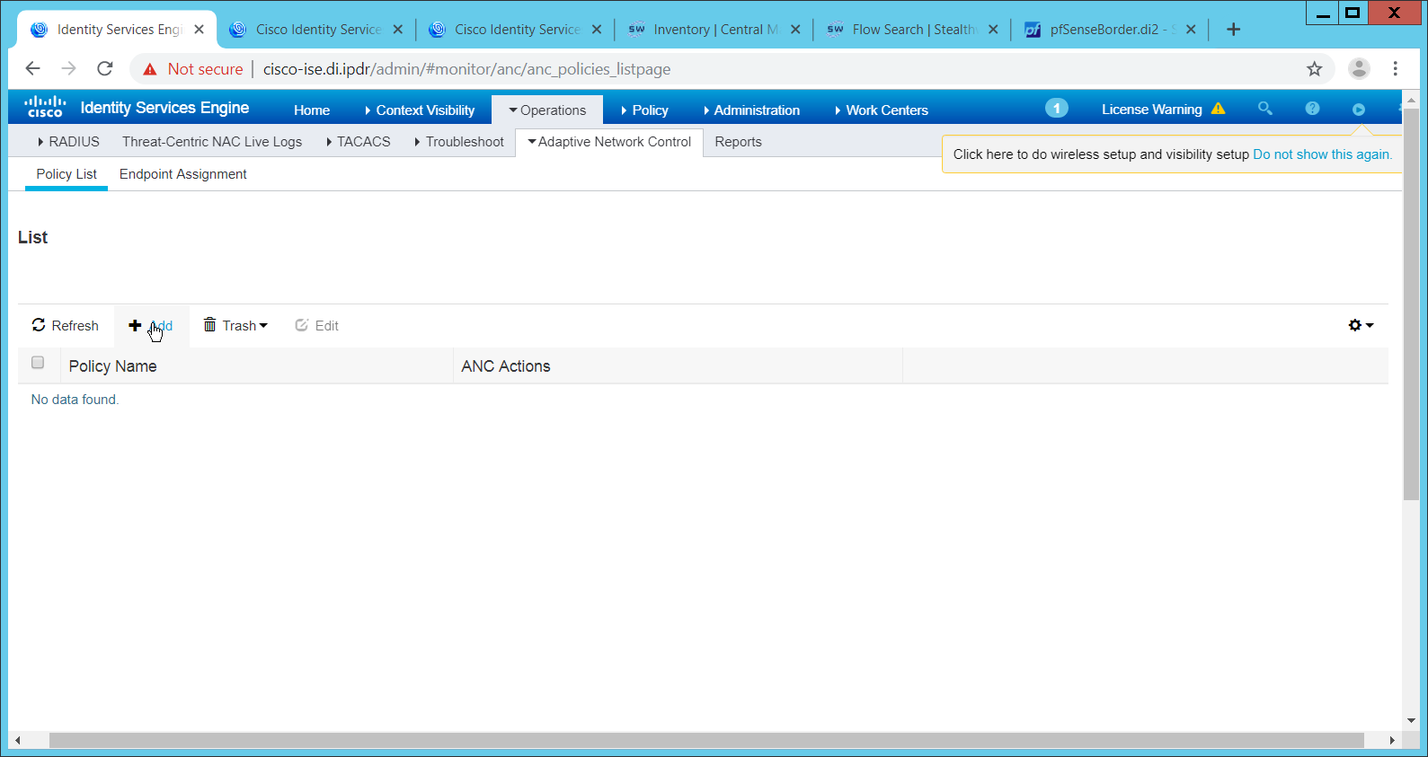
Click Add.
Enter a name for a quarantine action.
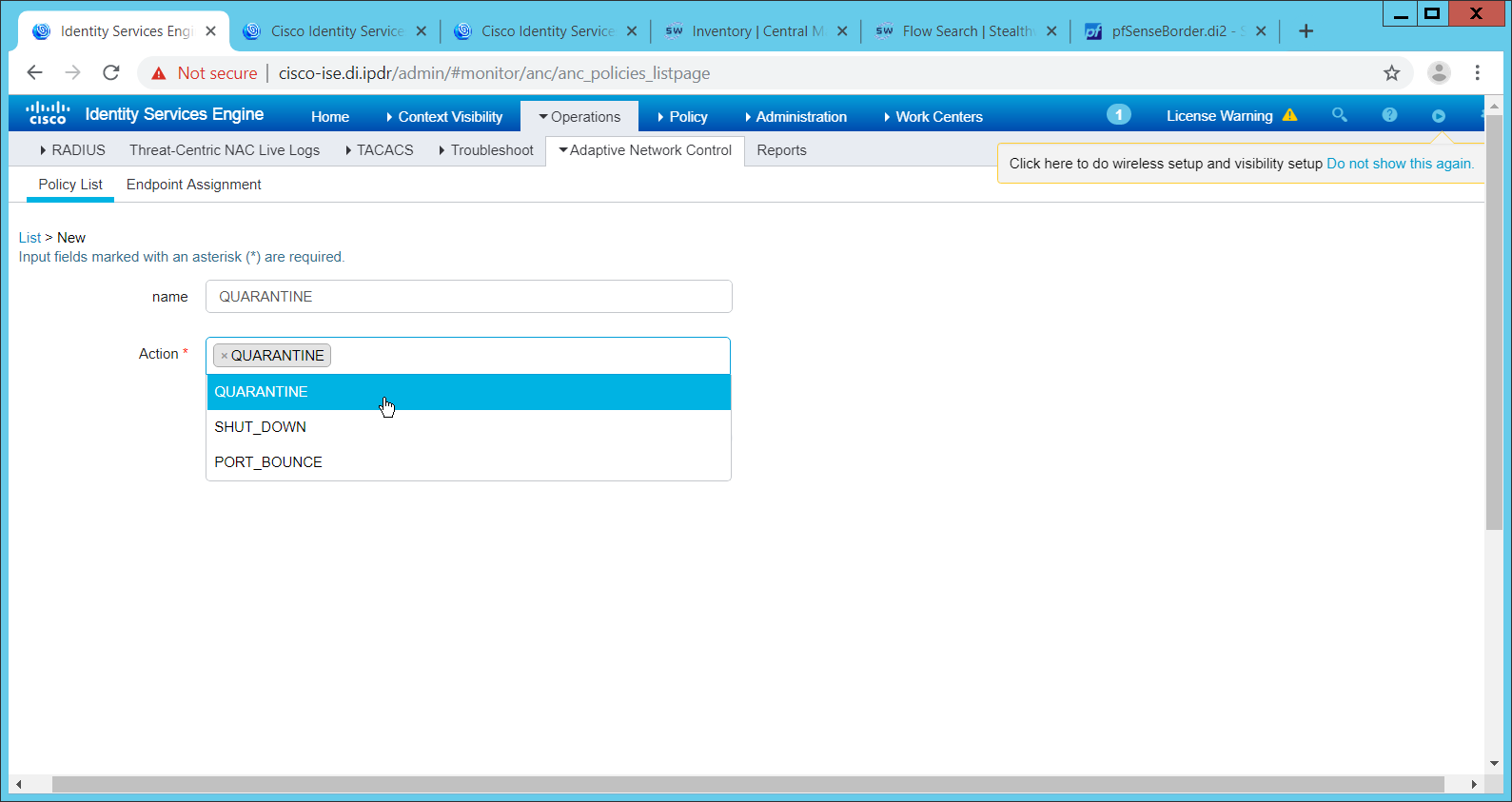
Select QUARANTINE for the Action.
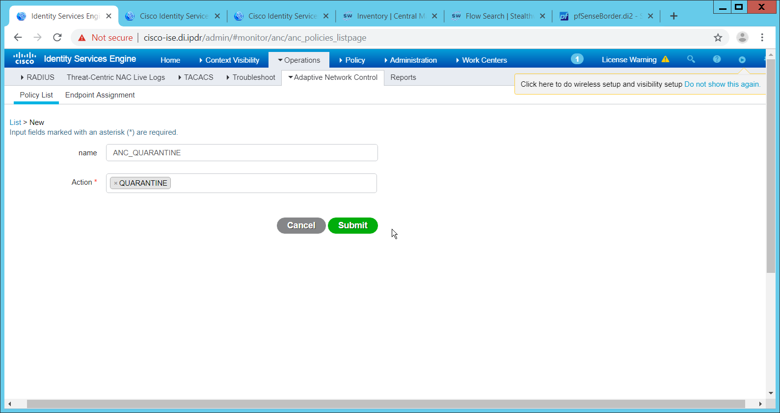
Click Submit.
Navigate to Policy > Policy Sets.
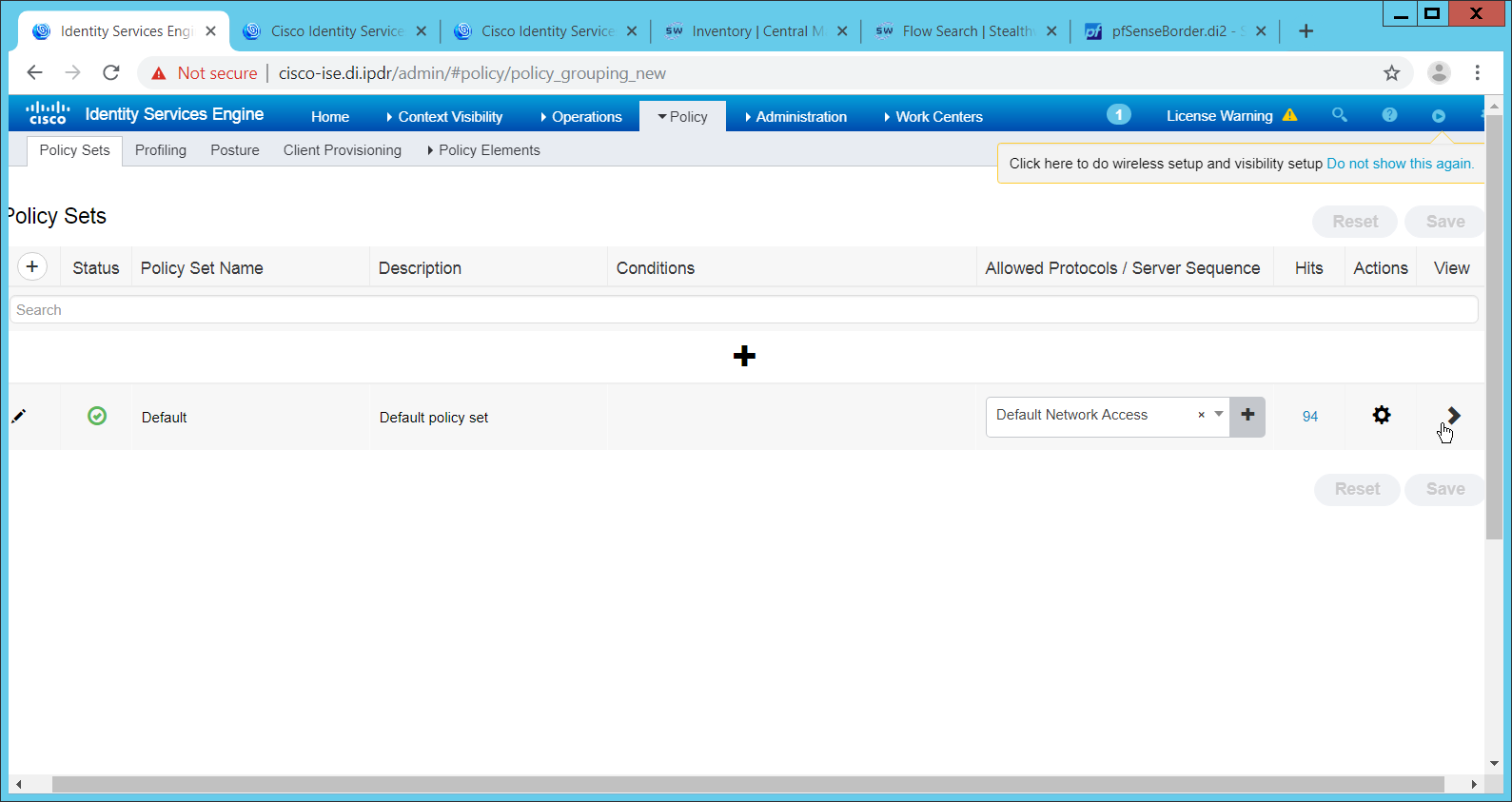
Click the > arrow next to the default policy set.
Expand the Authorization Policy - Global Exceptions section.
Click the + plus sign to add a new policy.
Click the + plus sign under Conditions.
Select the field Session – ANCPolicy.
Select the quarantine action you just created for the Attribute value.
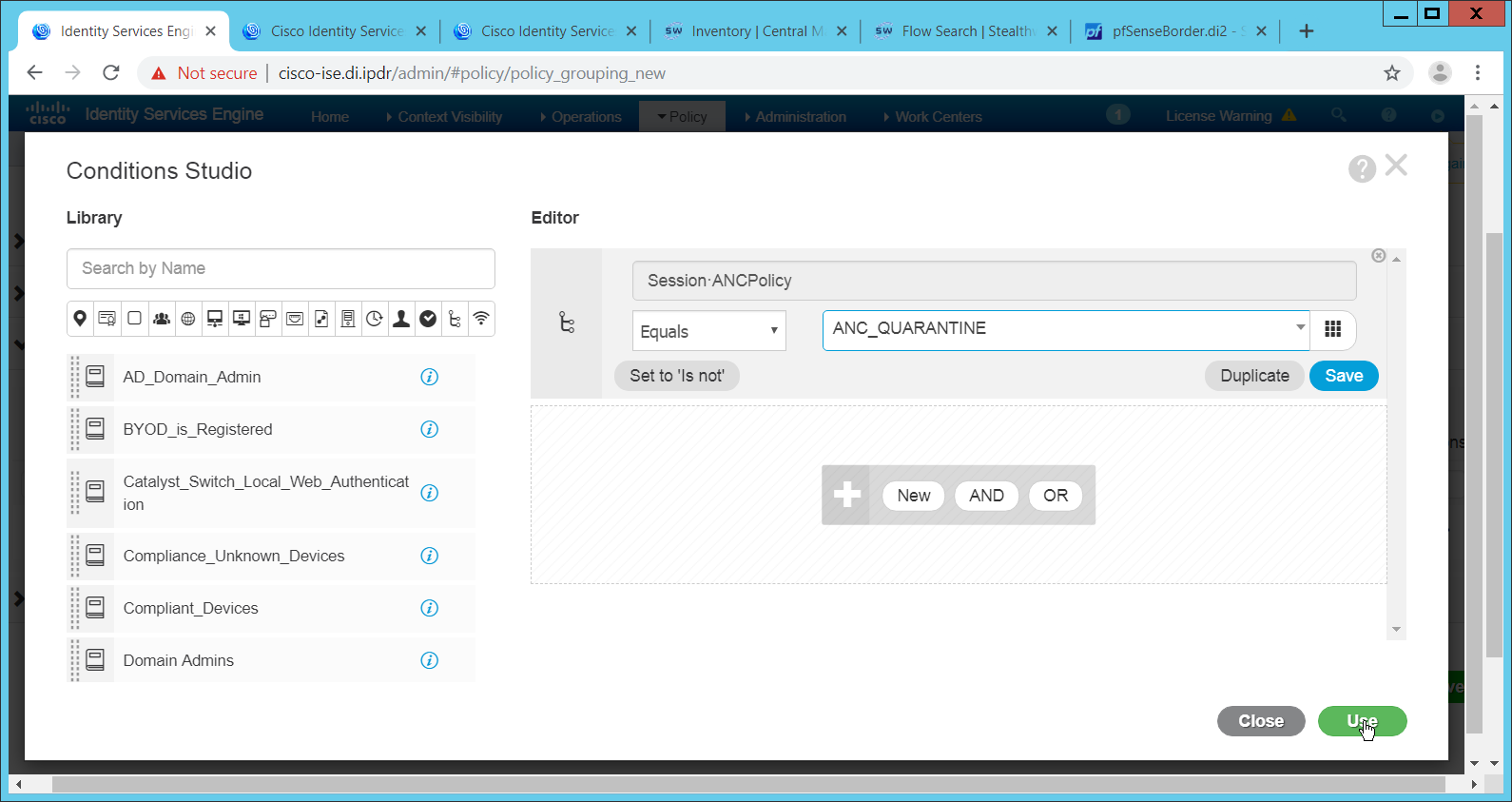
Click Use.
Select the Deny Access profile; the profile selected here will be applied to the machine when the machine is added to the quarantine group.
Select Quarantined_Systems for Security Groups.
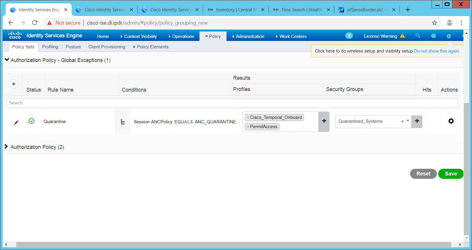
Click Save.
In the SMC web console, click Monitor > Users.
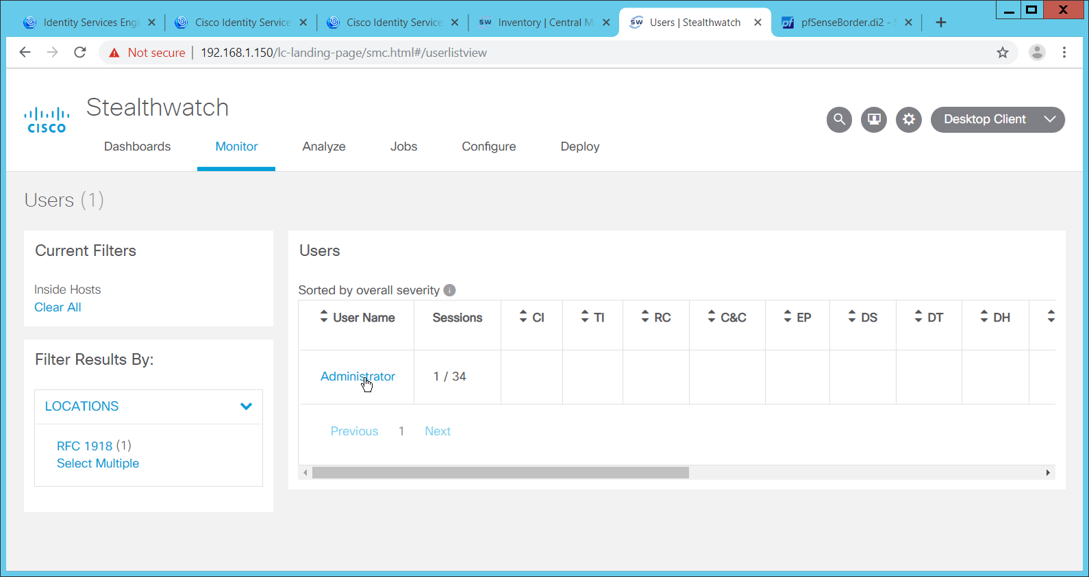
Select a user to quarantine.
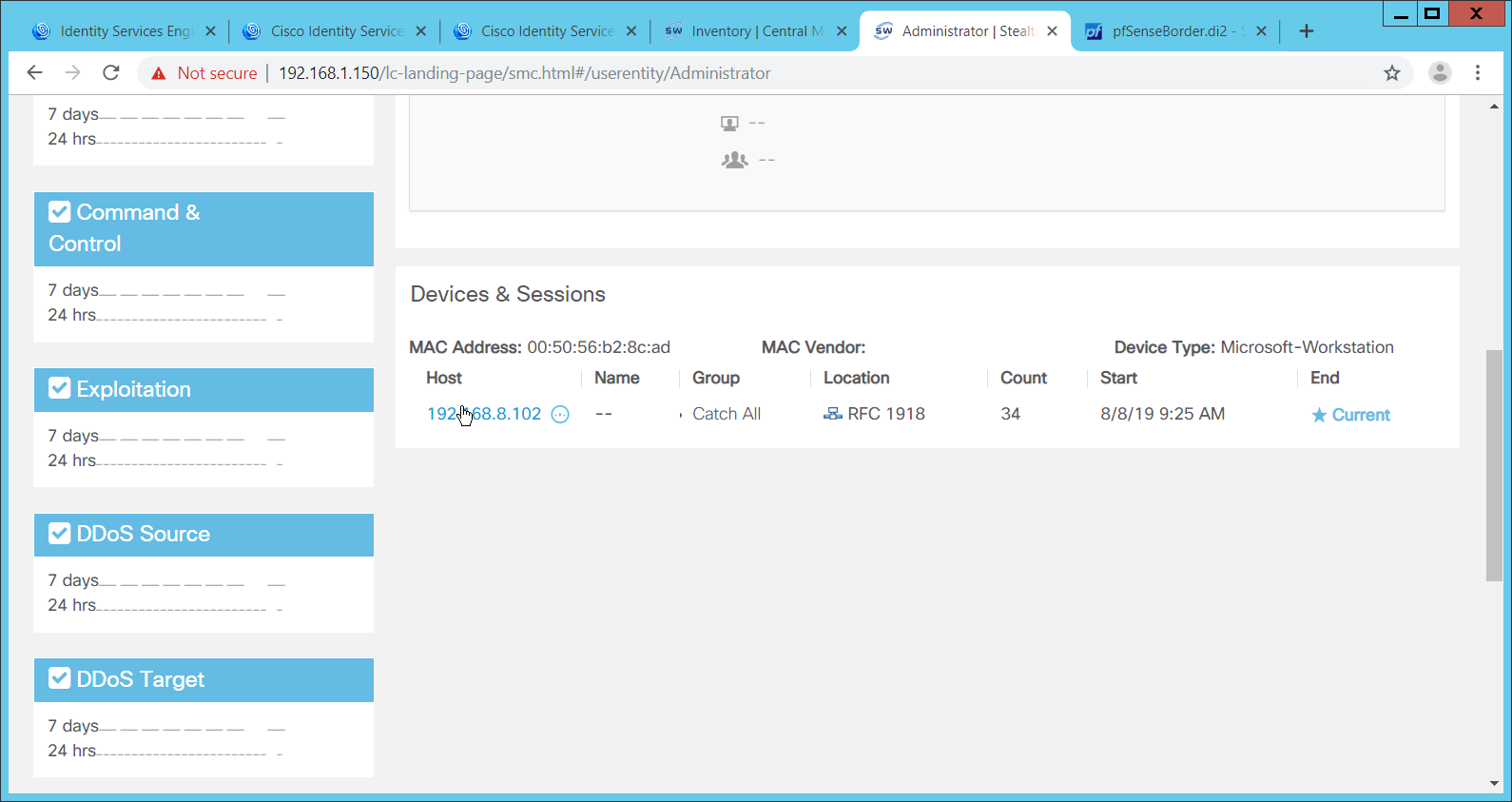
Click a host to quarantine.
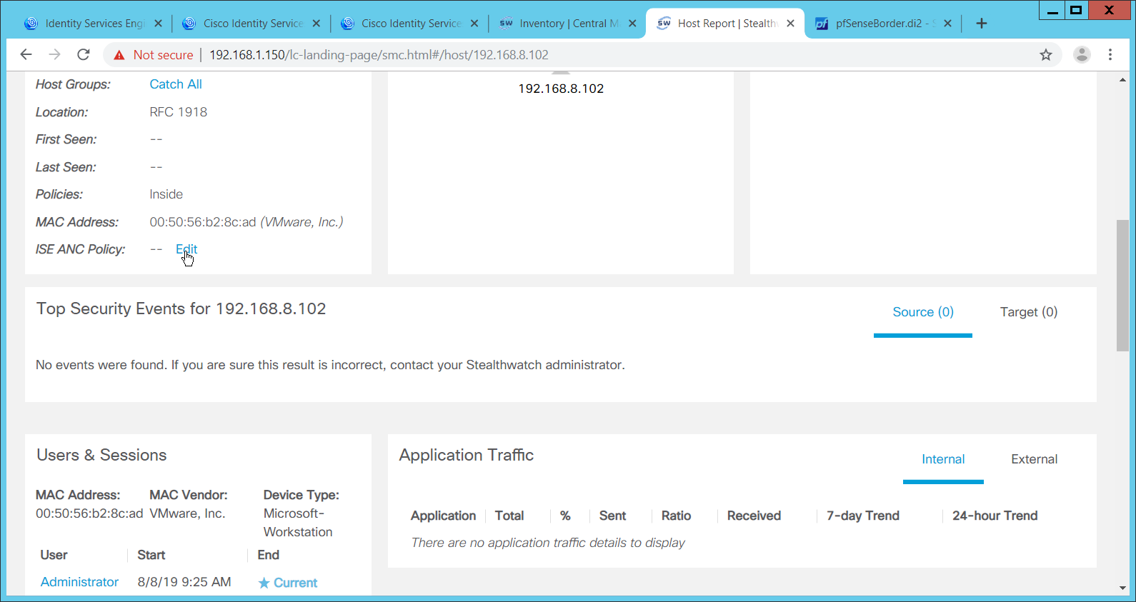
Click Edit next to ISE ANC Policy.
From the drop down, select the quarantine action you created earlier.
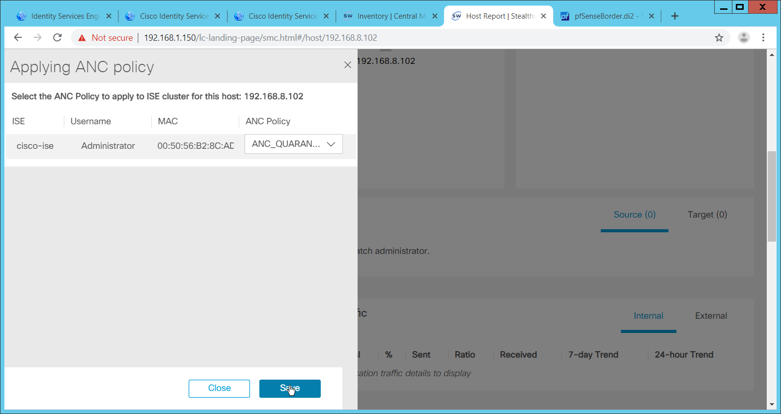
Click Save.
This will apply the quarantine action to the machine.
2.17 Integration: Tripwire Log Center and Tripwire Enterprise
Create a user account in Tripwire Log Center by logging into Tripwire Log Center Console.
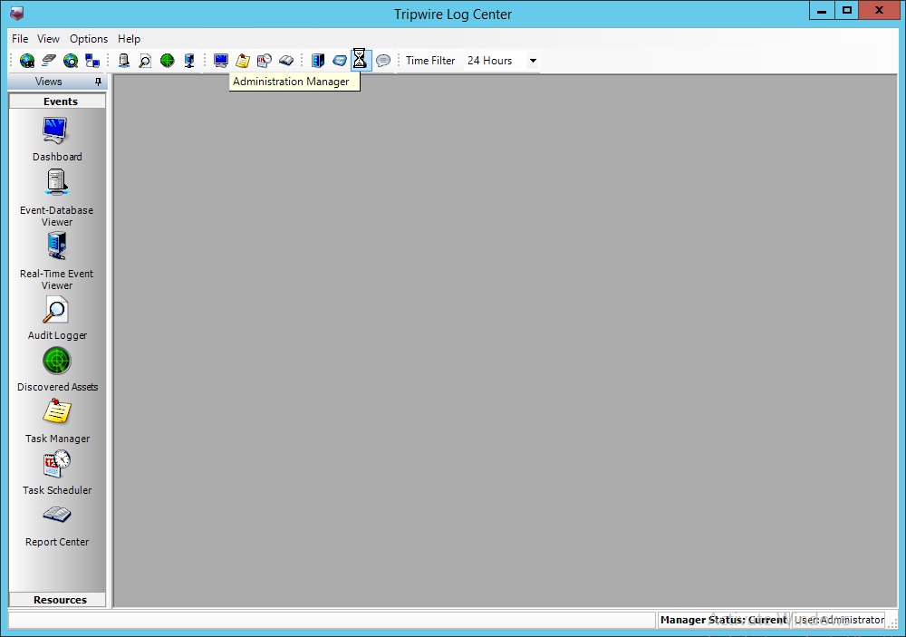
Click the Administration Manager button.
Click User Accounts.
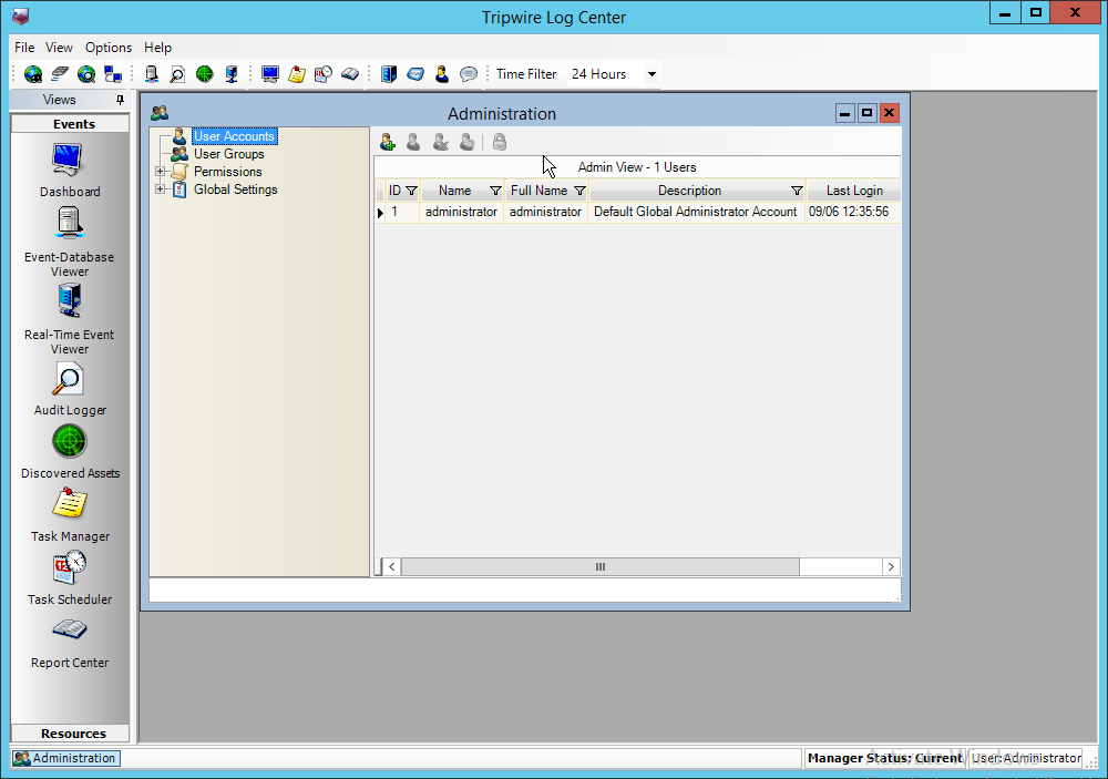
Click the Add button.
Enter the details of the user.
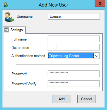
Click Add.
Double-click the user account.
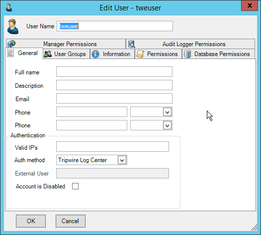
Click the Permissions tab.
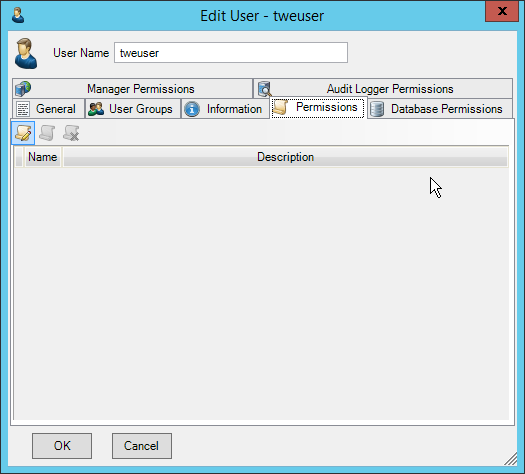
Click Edit list of permissions.
Select Databases.
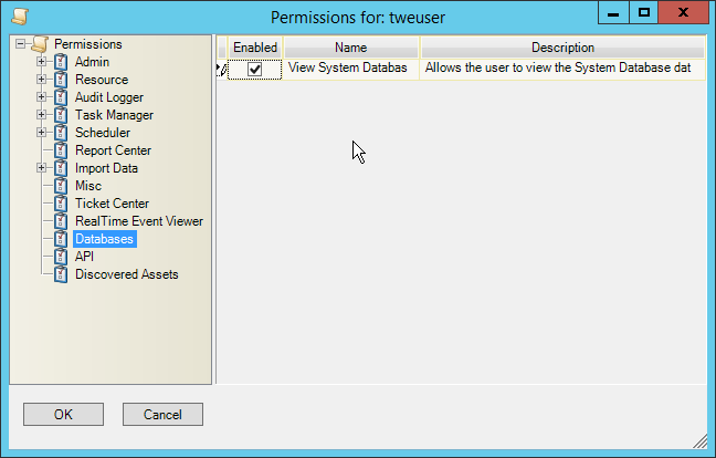
Check the box next to View System Database.
Select API.
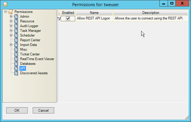
Check the box next to Allow REST API Logon.
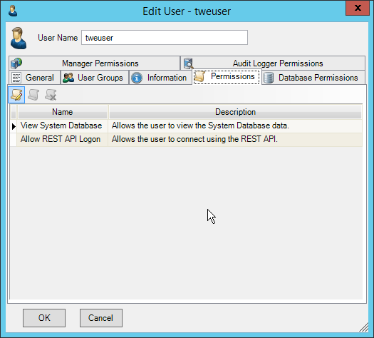
Click OK.
Click OK.
Log in to the Tripwire Enterprise web console.
Click Settings.
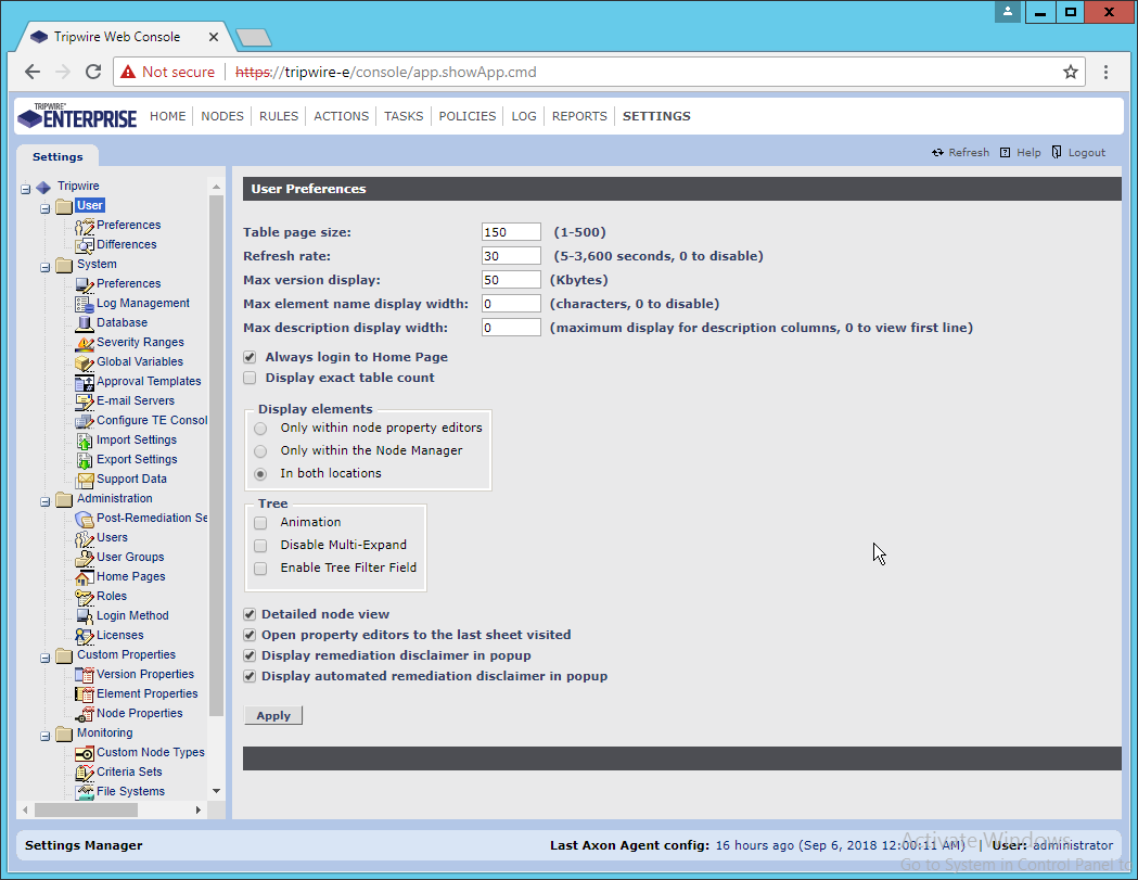
Go to System > Log Management.
Check the box next to Forward TE log messages to syslog.
Enter the hostname and port of the Tripwire Log Center server. The default port is 1468.
Check the box next to Allow TE to use information from Tripwire Log Center.
Enter the service address like this: https://arcsight-cons.di.ipdr:8091/tlc, replacing the hostname with the hostname of your Tripwire Log Center server.
Enter the account information of the account just created for Tripwire Log Center.
You can use Test Connection to verify that the connection is working.
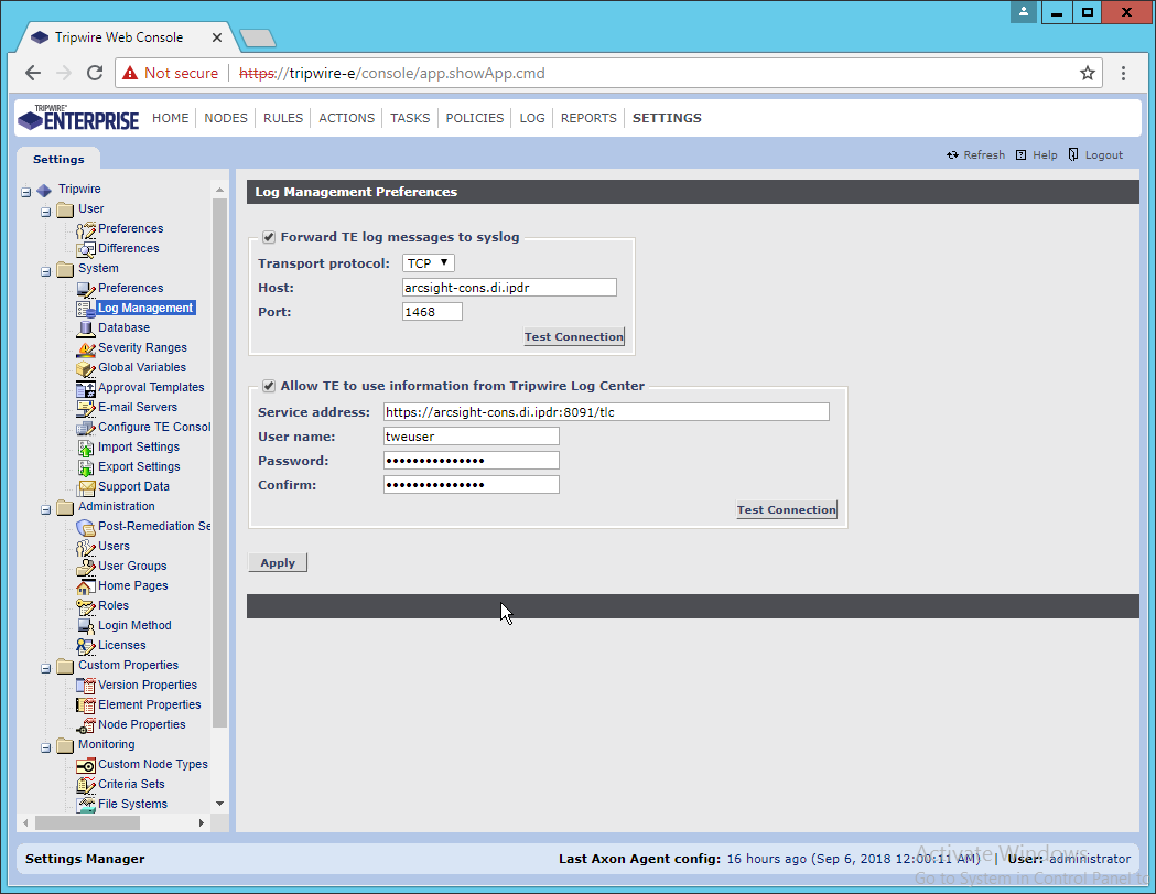
Click Apply when finished.
Go back to the Tripwire Log Center Console.
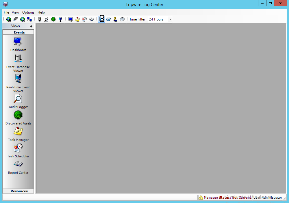
Click Configuration Manager.
Click Resources > Tripwire Enterprise Servers.
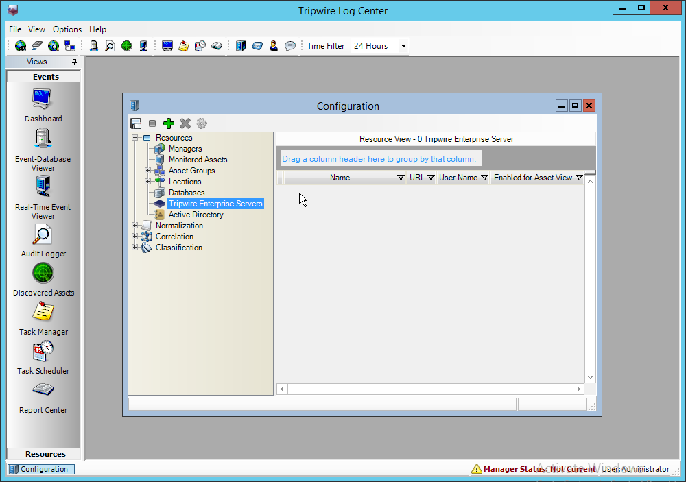
Click Add.
Enter a name for the server.
Enter the URL of the TE server.
Enter the name of a user account on the TE server. The account must have the following permissions: create, delete, link, load, update, view.
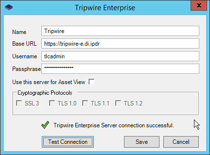
Click Save.
2.18 Integration: Symantec ICA and ArcSight ESM
This section describes the integration of Symantec ICA and ArcSight ESM, to import data from ArcSight into ICA for analysis. For the purposes of this build, we did not use ArcSight Logger, a tool which provides a web Application Programming Interface (API) for other applications. Because of this, the standard integration between ICA and ESM was unavailable. However, it is still possible to import Comma-Separated Values (CSV) files exported from ArcSight into ICA, and we will detail the process below. There are a few things to note when doing this import:
On the version of Symantec ICA we are using, it is required to replace empty fields in the CSV with NULL. This may be unnecessary in future updates.
The CSV file should be in a location accessible to the ICA server. You can replace this file with a new CSV file on a daily basis, and Symantec ICA has the capability to import the new data.
The following integration details how to do it for a subset of fields on Active Directory logging events, but the process can be expanded for your organization’s needs.
2.18.1 Export the CSV File from ArcSight Console
In ArcSight Console, find a connector which you wish to import events from. Right-click it, and select Create Channel with Filter.
In the channel, apply any filters desired.
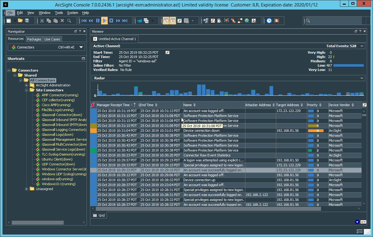
When finished, right-click any of the events in the channel, and select Export > Events in Channel….
Enter a name for the CSV file for File name:.
Select All in Channel for Rows:.
For Columns: either select a custom field-set to determine the output columns or leave the default selected.
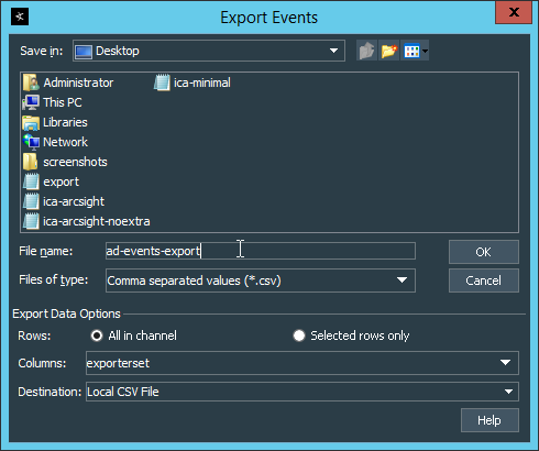
Click OK.
Move the file to the desired location for ICA to collect. (Ensure that if required for your version of Symantec ICA, all empty fields are replaced with “NULL”) For the purposes of this demonstration, we moved it to C:\Temp\unprocessed on the Symantec ICA server.
2.18.2 Import the CSV File to Symantec ICA
On the Symantec ICA web console, navigate to Gear Icon > Integration.
Click the Data Sources tab.
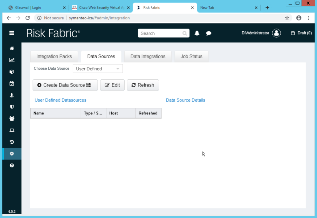
Select User Defined for Choose Data Source.
Click Create Data Source.
Select File System IW for the Data Source Type.
Enter a name for the data source for Data Source Label.
Enter the hostname of the Symantec ICA server for Server Name.
Select Windows/Active Directory for the Authentication Mode.
Enter the location for the downloaded CSV file for Download Directory (relative to the Symantec ICA server).
Enter the location for the CSV file to be downloaded from for Source Folder (relative to the Symantec ICA server).
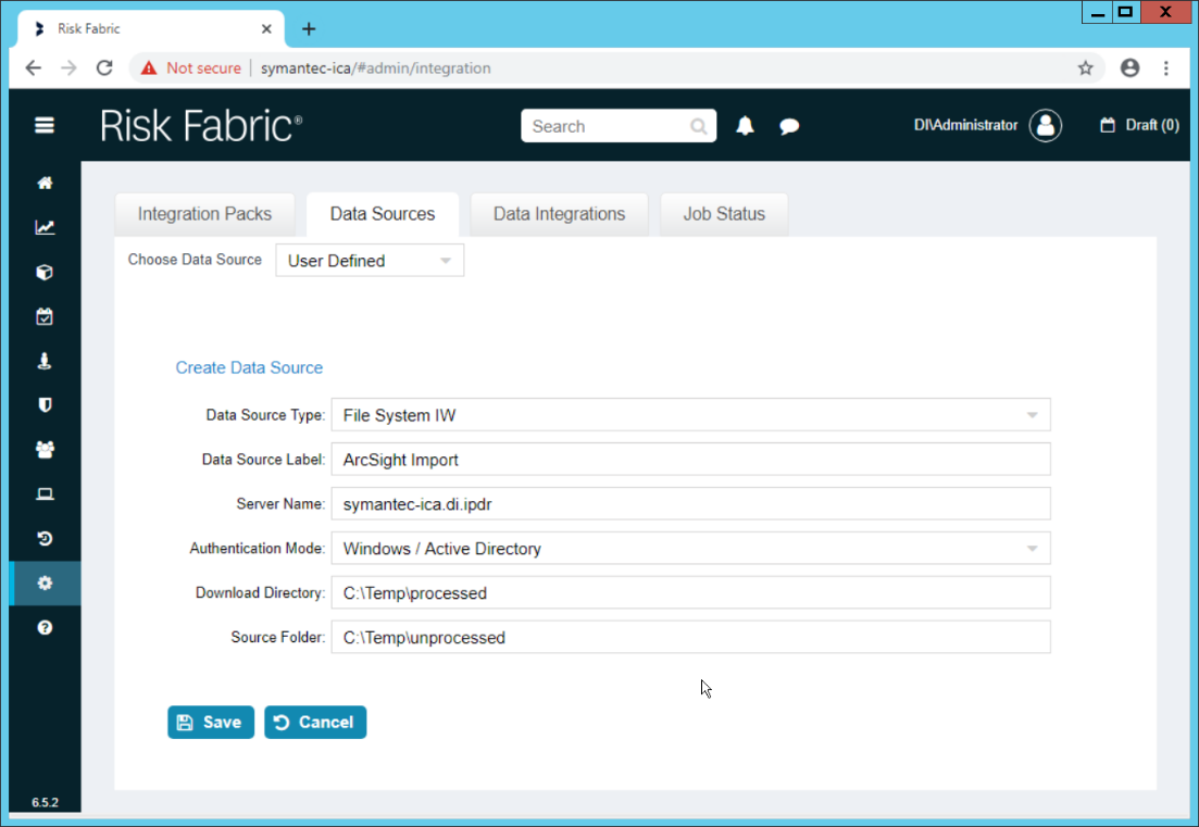
Click Save.
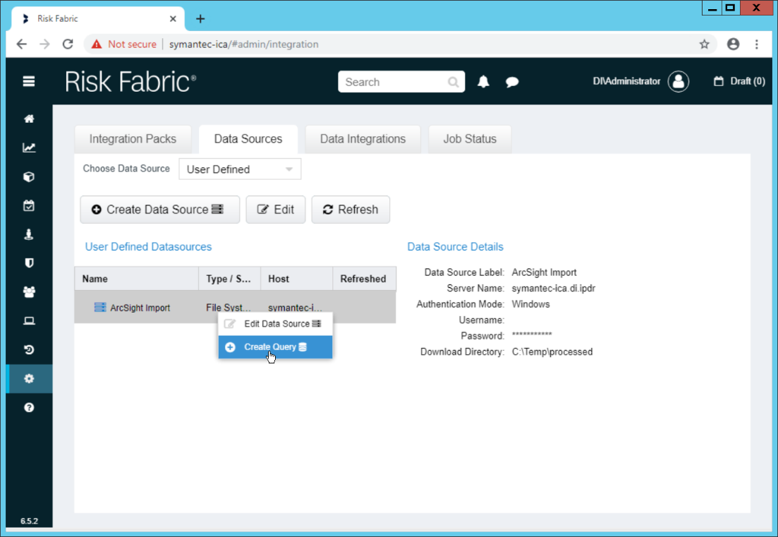
Right-click the newly created data source and select Create Query.
Enter a Query Name and Query Description.
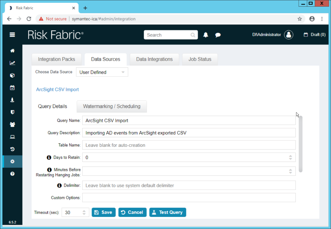
If you specified the Source Folder correctly, you will see the CSV file listed.
Check the box next to any CSVs to import.
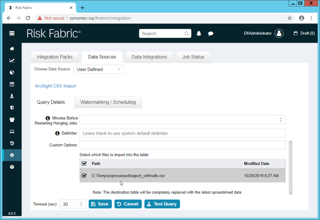
Click Save.
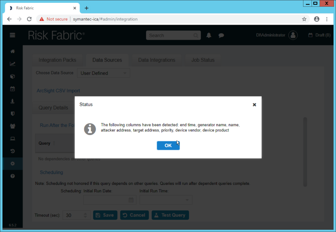
Click OK.
If desired, set a schedule for this import.
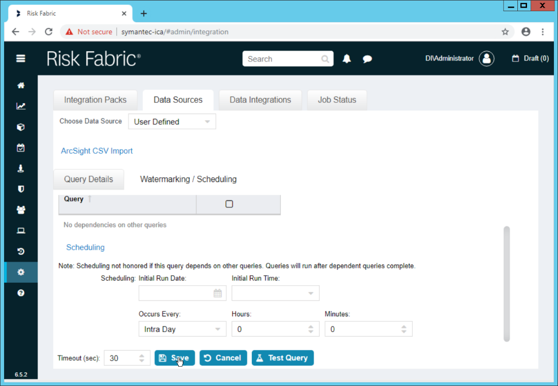
Click Save.
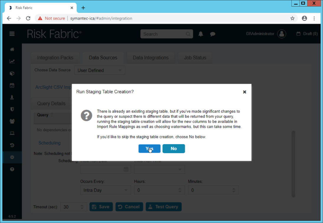
Click Yes.
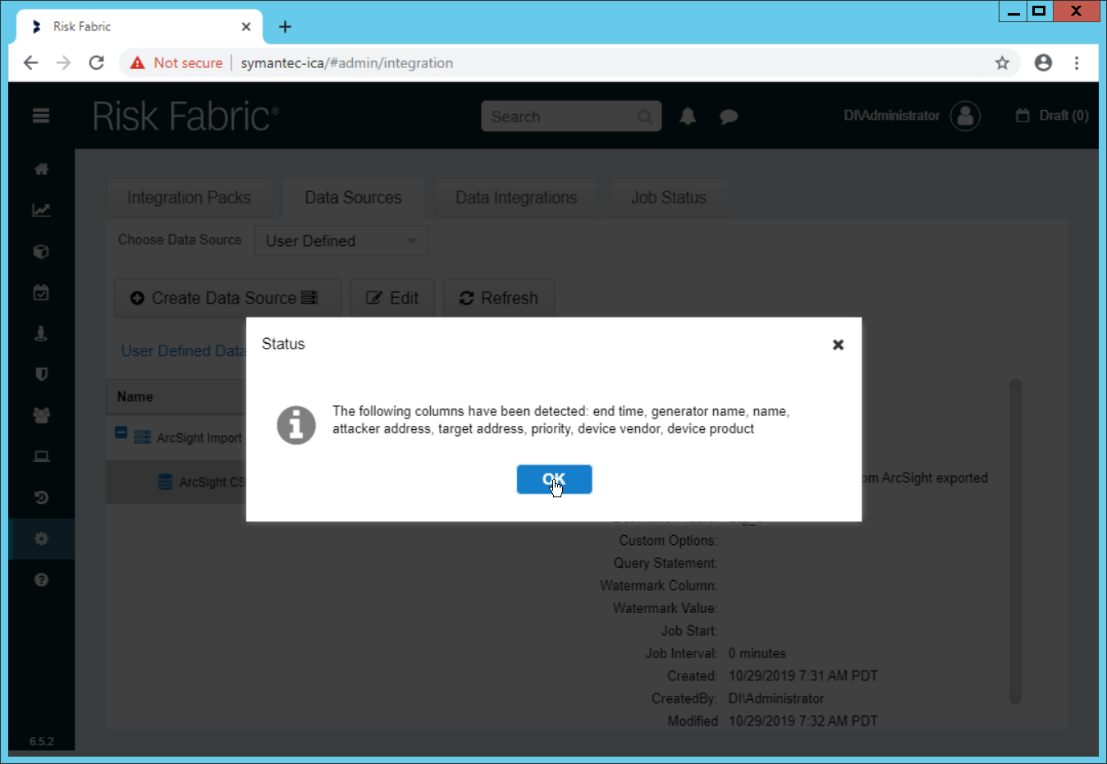
Click OK.
2.18.3 Create a Mapping between ArcSight events and Symantec ICA
Navigate to the Data Integrations tab.
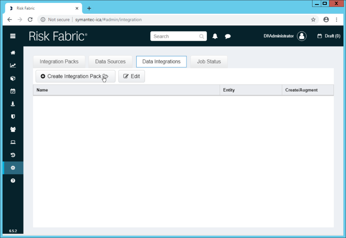
Click Create Integration Pack.
Enter a Name and Description.
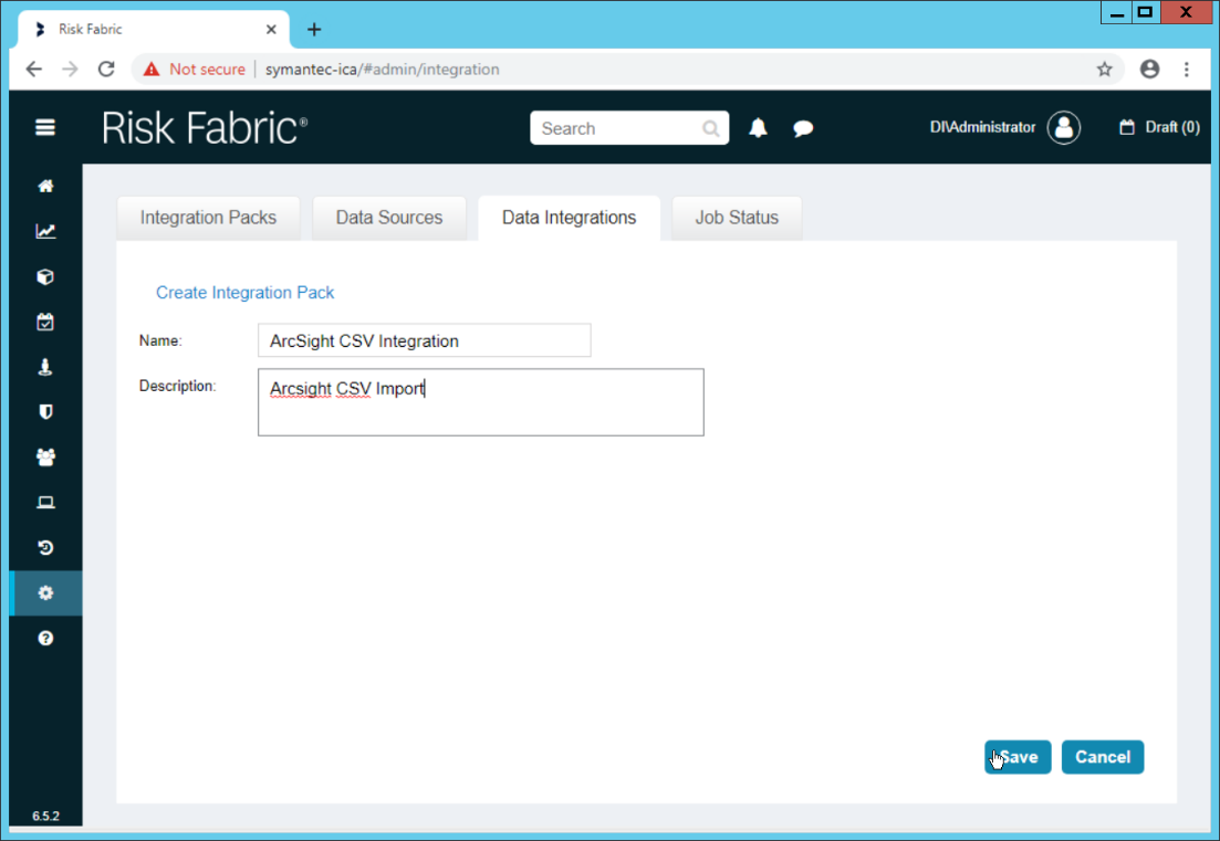
Click Save.
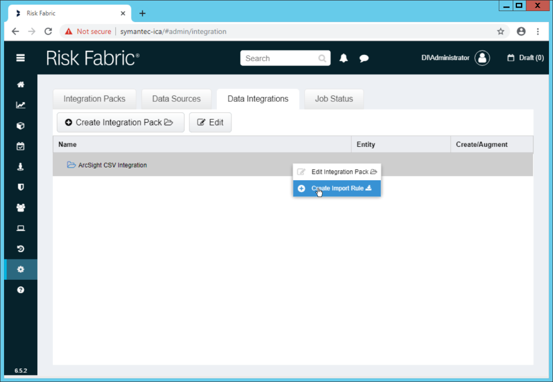
Right-click the newly created Integration Pack, and select Create Import Rule.
Enter a Name and Description.

Click Save.
Right-click the newly created Import Rule and select Create Import Rule Mapping.
Enter a Name for the mapping.
Enter a Description.
Select the Data Source created earlier.
Select the Query created earlier.
Select EP Events for the Entity Type (or explore other Entity Types that may better match the events you are importing).
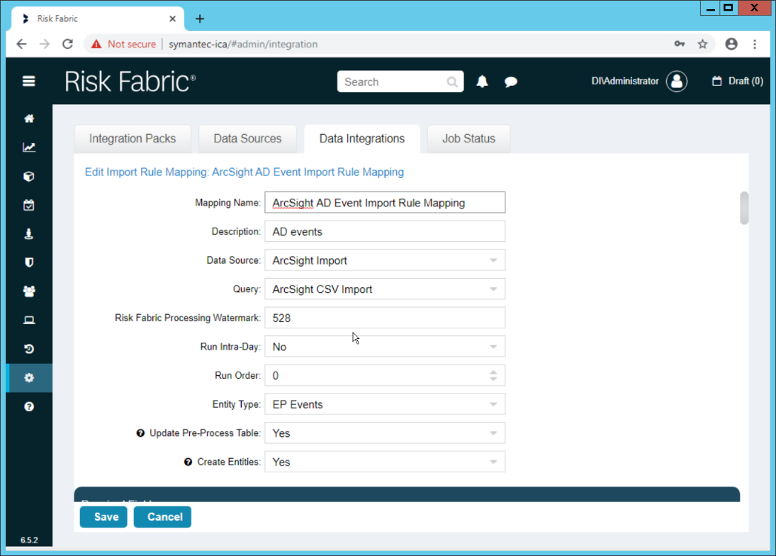
Below, the Entity Column refers to the target field in ICA to which a field is being mapped. Map event fields from the CSV to fields in the Entity Column.
For example, EventDate in ICA corresponds directly to the End Time in ArcSight, so we select that value directly as a Source Column for the mapping.
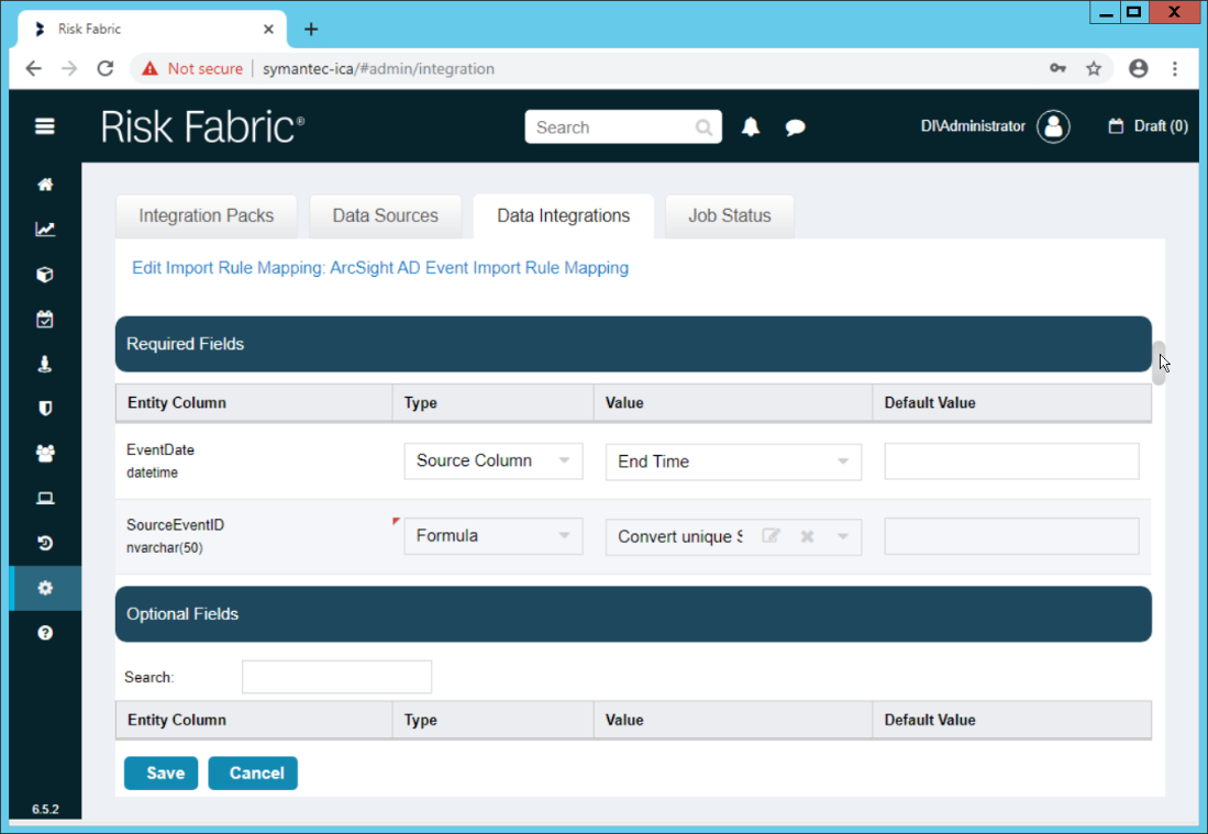
Formulas can be used to transform columns in the CSV to something more specific in ICA. Because we did not export an event ID to our CSV file, we use a formula to create a hash of the End Time and use that as the ID.
All Required Fields must be mapped, and you will likely also want to map some optional fields to make useful data.
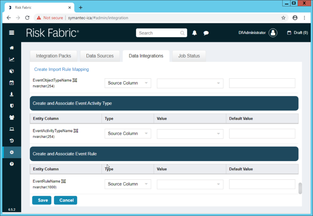
Click Save when finished.
Navigate to the Job Status tab.
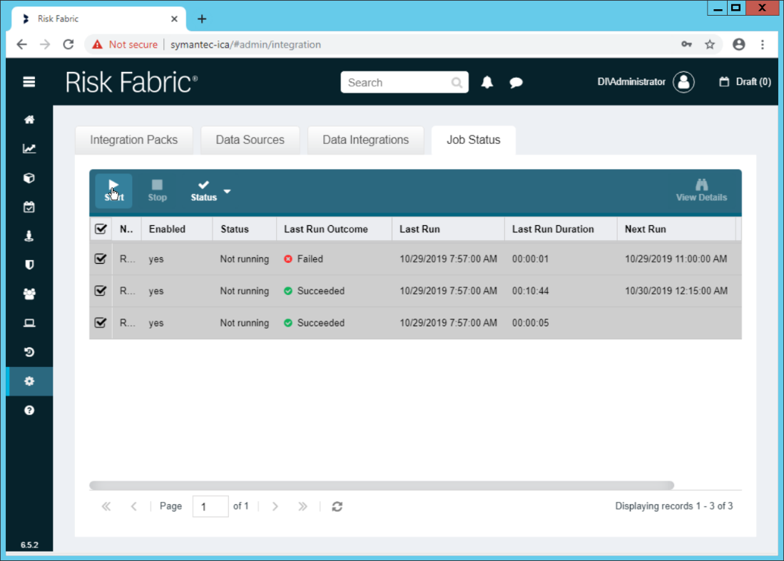
Select all the jobs and click Start. This is to force a refresh of the ICA processing, allowing the data from the CSV to be imported immediately.
2.18.4 View ArcSight Events in the Analyzer
Once the processing jobs are finished, navigate to the Analyzer.
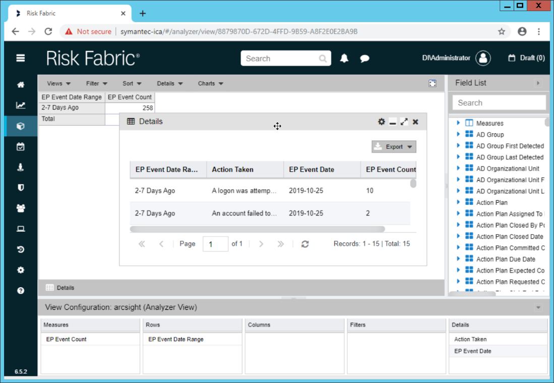
Drag mapped columns (from the import rule mapping you created) from the list on the right to view them in the analyzer.
2.19 Integration: Micro Focus ArcSight and Tripwire
This section will detail the forwarding of logs from Tripwire Log Center to Micro Focus ArcSight. This will forward Tripwire IP360 and Tripwire Enterprise logs to ArcSight, assuming those logs are being collected by Tripwire Log Center.
2.19.1 Install Micro Focus ArcSight
Run ArcSight-7.9.0.8084.0-Connector-Win64.exe on any server except the one running Tripwire Log Center.
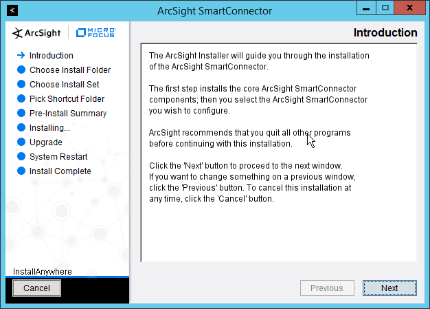
Click Next.

Enter C:\Program Files\ArcSightSmartConnectors\Tripwire.
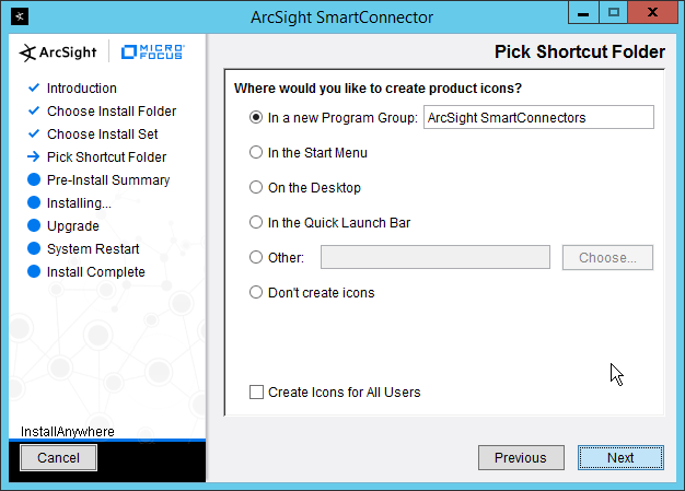
Click Next.
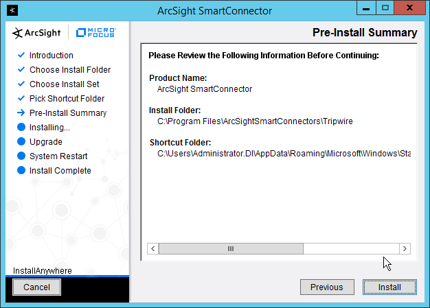
Click Install.
Select Add a Connector.
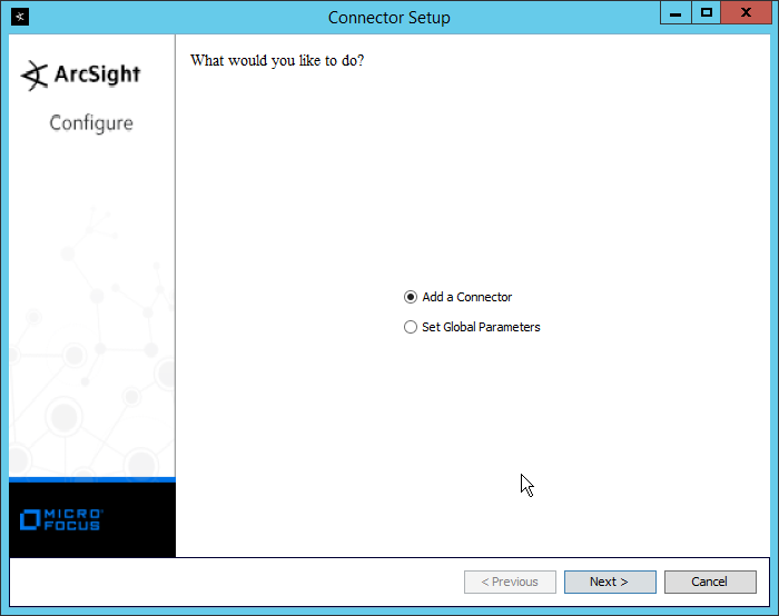
Click Next.
Select Syslog Daemon.

Click Next.
Enter a port for the daemon to run on.
Select Raw TCP for Protocol.

Click Next.
Select ArcSight Manager (encrypted).
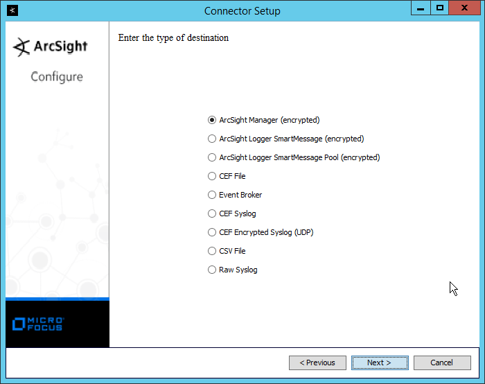
Click Next.
Enter the hostname, port, username, and password for the ArcSight ESM server.

Click Next.
Enter identifying details about the system (only Name is required).

Click Next.
Select Import the certificate to connector from destination.
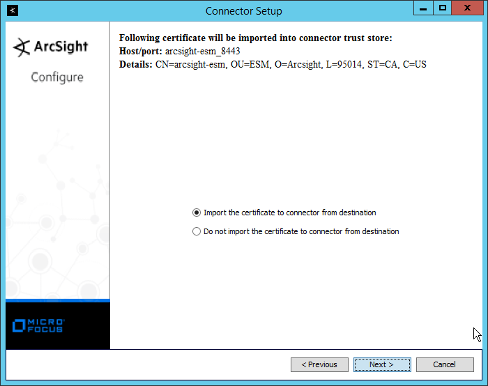
Click Next.

Click Next.
Select Install as a service.

Click Next.

Click Next.
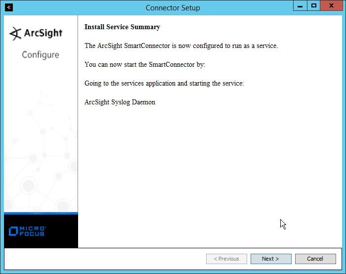
Click Next.
Select Exit.

Click Next.
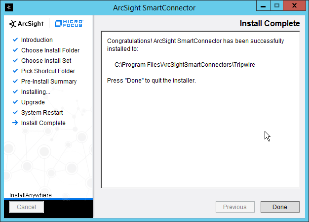
Click Done.
Open the Tripwire Log Center Console.
Go to the Configuration Manager.
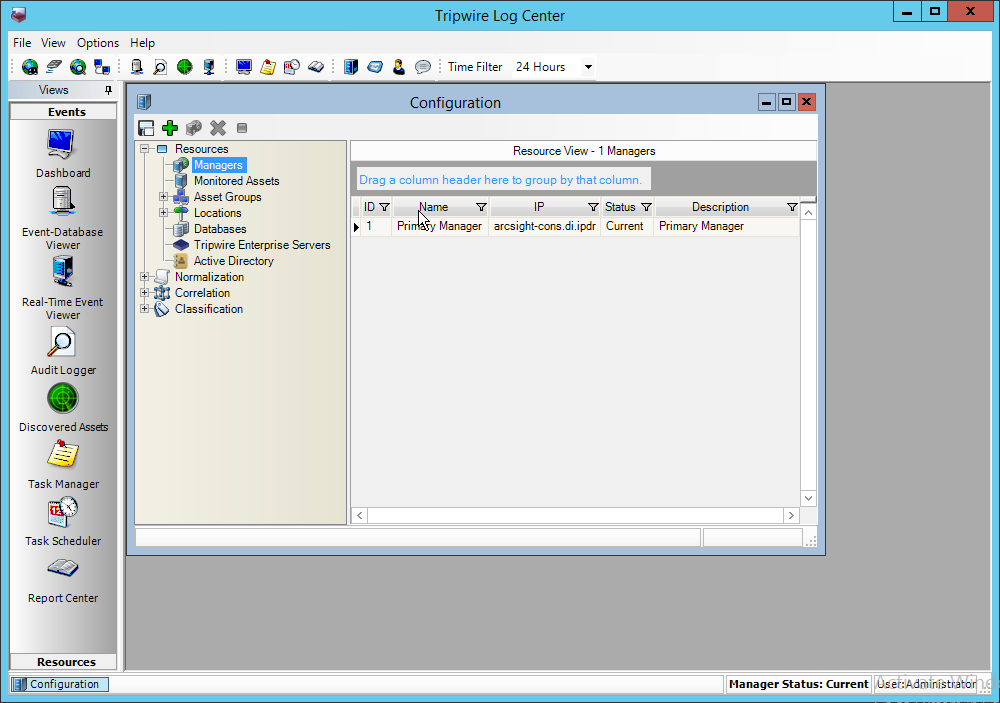
Select Resources > Managers.
Double-click the Primary Manager.
Click the Advanced Settings tab.
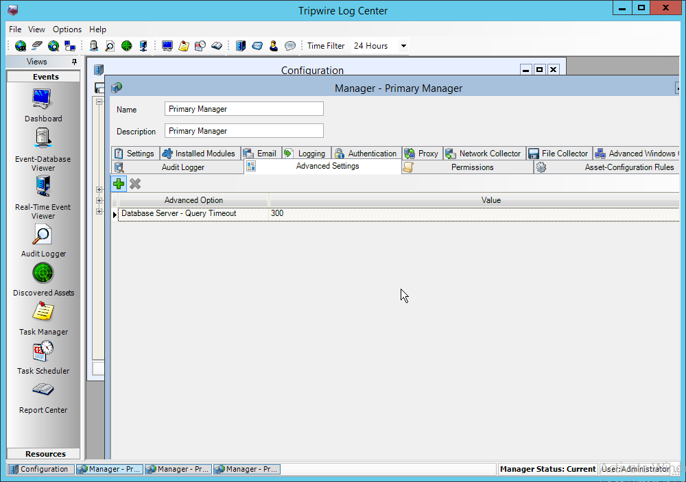
Click the Add button.
In the Advanced Option box select Log Message Forwarding – Destinations.
In the Value box next to it, type <ip_address>:<port>:tcp with the IP address and port of the syslog daemon just created.
Click OK.
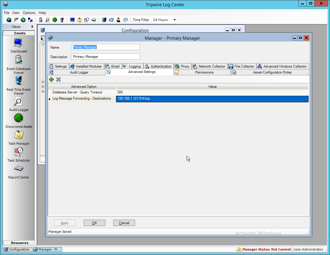
Click OK.
Restart the Tripwire Log Center Manager.
2.20 Integration: Micro Focus ArcSight and Cisco AMP
This section will detail the collection of logs from Cisco AMP’s REST APIs using Micro Focus ArcSight.
2.20.1 Create API Credentials for ArcSight to access AMP
On the Cisco AMP web console, log in and navigate to Accounts > API Credentials.
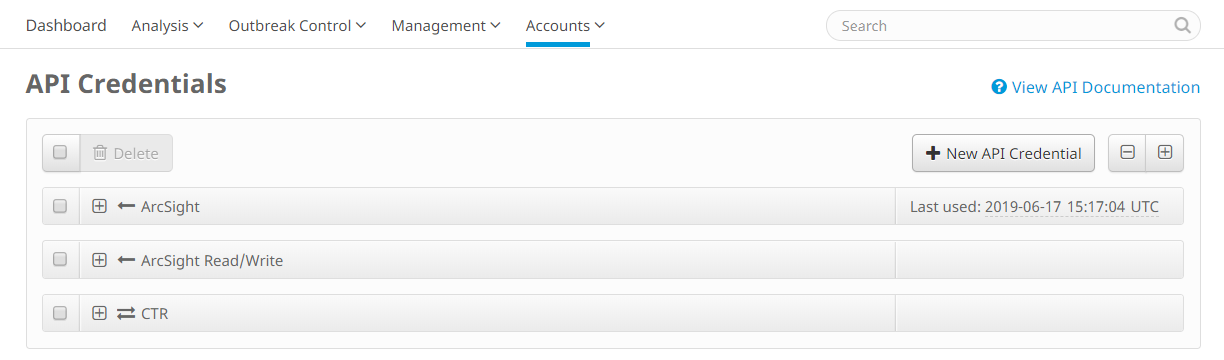
Click New API Credential.
Enter a name for the credential.
Select Read-only.
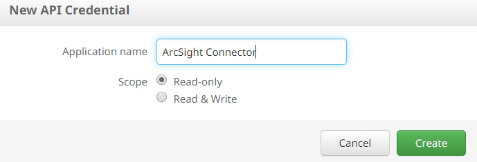
Click Create.
This will direct you to a page with an ID and API Key. Keep track of these, as you will need them in the setup for the ArcSight Connector, and Cisco AMP may not let you view them again.
2.20.2 Install Micro Focus ArcSight
Run ArcSight-7.9.0.8084.0-Connector-Win64.exe on any server.
Click Next.
Enter C:\Program Files\ArcSightSmartConnectors\CiscoAMP.
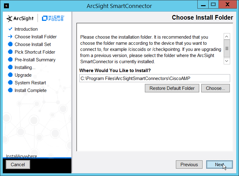
Click Next.

Click Next.
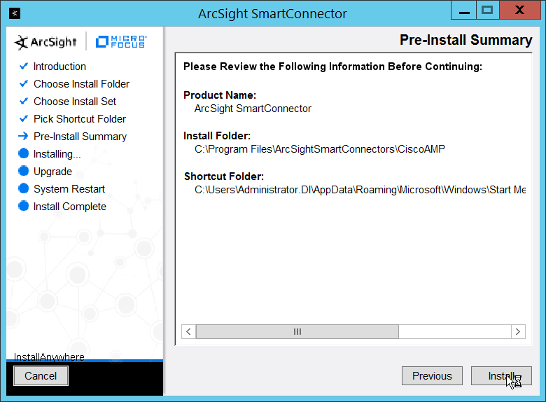
Click Install.
Select Add a Connector.

Click Next.
Select ArcSight FlexConnector REST.

Click Next.
Enter Cisco_AMP for the Configuration File.
Enter https://api.amp.cisco.com/v1/events?start_date=$START_AT_TIME for the Events URL. (Note: You can see the Cisco AMP REST API documentation for more information on how to formulate this URL for things other than events.)
Enter the username and password from the credential generated on Cisco AMP in Section 2.20.1.
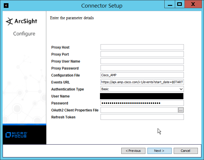
Click Next.
Select ArcSight Manager (encrypted).

Click Next.
Enter the hostname, port, username, and password for the ArcSight ESM server.
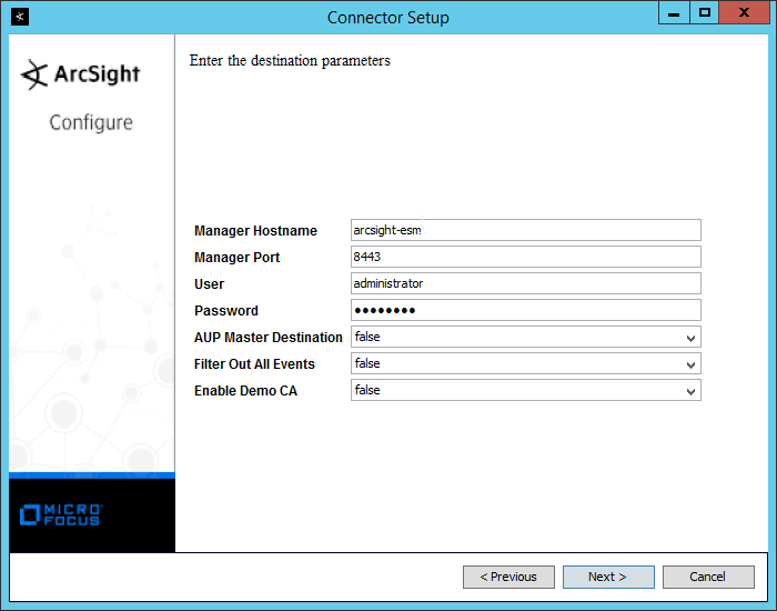
Click Next.
Enter identifying details about the system (only Name is required).

Click Next.
Select Import the certificate to connector from destination.
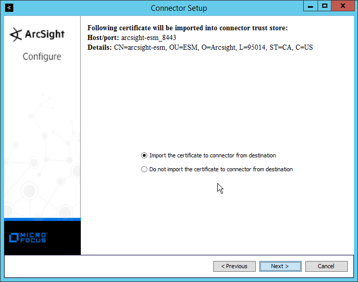
Click Next.
Click Next.
Select Install as a service.

Click Next.
Enter a service name and display name.
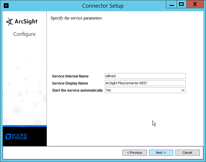
Click Next.
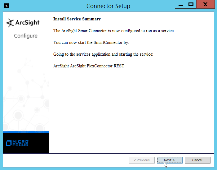
Click Next.
Select Exit.
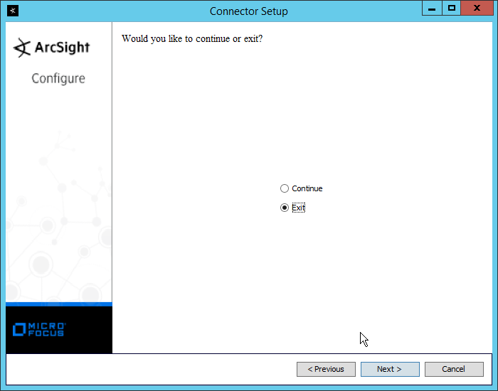
Click Next.
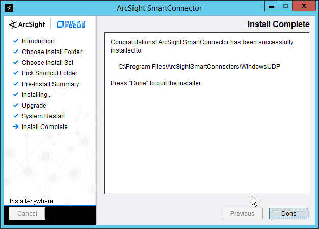
Click Done.
2.20.3 Create a Parser for Cisco AMP REST events
Ensure that the ArcSight connector service is not running.
Create a text file located at <ARCSIGHT_HOME>/current/user/agent/flexagent/Cisco_AMP.jsonparser.properties. (Note: Replace Cisco_AMP with the name used for “Configuration File” during setup.)
Use the following text to parse some basic information such as the IP, the type of event, and links to Cisco AMP’s more detailed descriptions of the event.
trigger.node.location=/data

token.count=6

token[0].name=id

token[0].type=String

token[0].location=id

token[1].name=timestamp

token[1].type=String

token[1].location=date

token[2].name=event_type

token[2].type=String

token[2].location=event_type

token[3].name=hostname

token[3].type=String

token[3].location=computer/hostname

token[4].name=external_ip

token[4].type=IPAddress

token[4].location=computer/external_ip

token[5].name=links

token[5].type=String

token[5].location=links

event.deviceReceiptTime=__createOptionalTimeStampFromString(timestamp,"yyyy-MM-dd'T'HH:mm:ssX")

event.destinationAddress=external_ip

event.destinationHostName=hostname

event.name=event_type

event.message=links

event.deviceCustomString1=id

event.deviceCustomString1Label=__stringConstant("AMP Event ID")
This parser will allow for details of Cisco AMP events to be shown in ArcSight. Custom parsers are a functionality of ArcSight. For more information on the creation of custom parsers, please see the ArcSight FlexConnector Developer’s Guide as well as the FlexConnector REST Developer’s Guide. You can start the service for these changes to take effect.
2.21 Integration: Micro Focus ArcSight and Cisco ISE
This integration will briefly detail how to send logs to an ArcSight syslog collector from Cisco ISE. Please see Section 2.18 (under integrating Tripwire & ArcSight) for instructions for setting up an ArcSight syslog collector. If a server is already configured, you do not need to install a new one—use the address of that server to which to forward logs.
2.21.1 Configure Cisco ISE to Forward Logs
In the Cisco ISE web client, navigate to Administration > System > Logging > Remote Logging Targets.
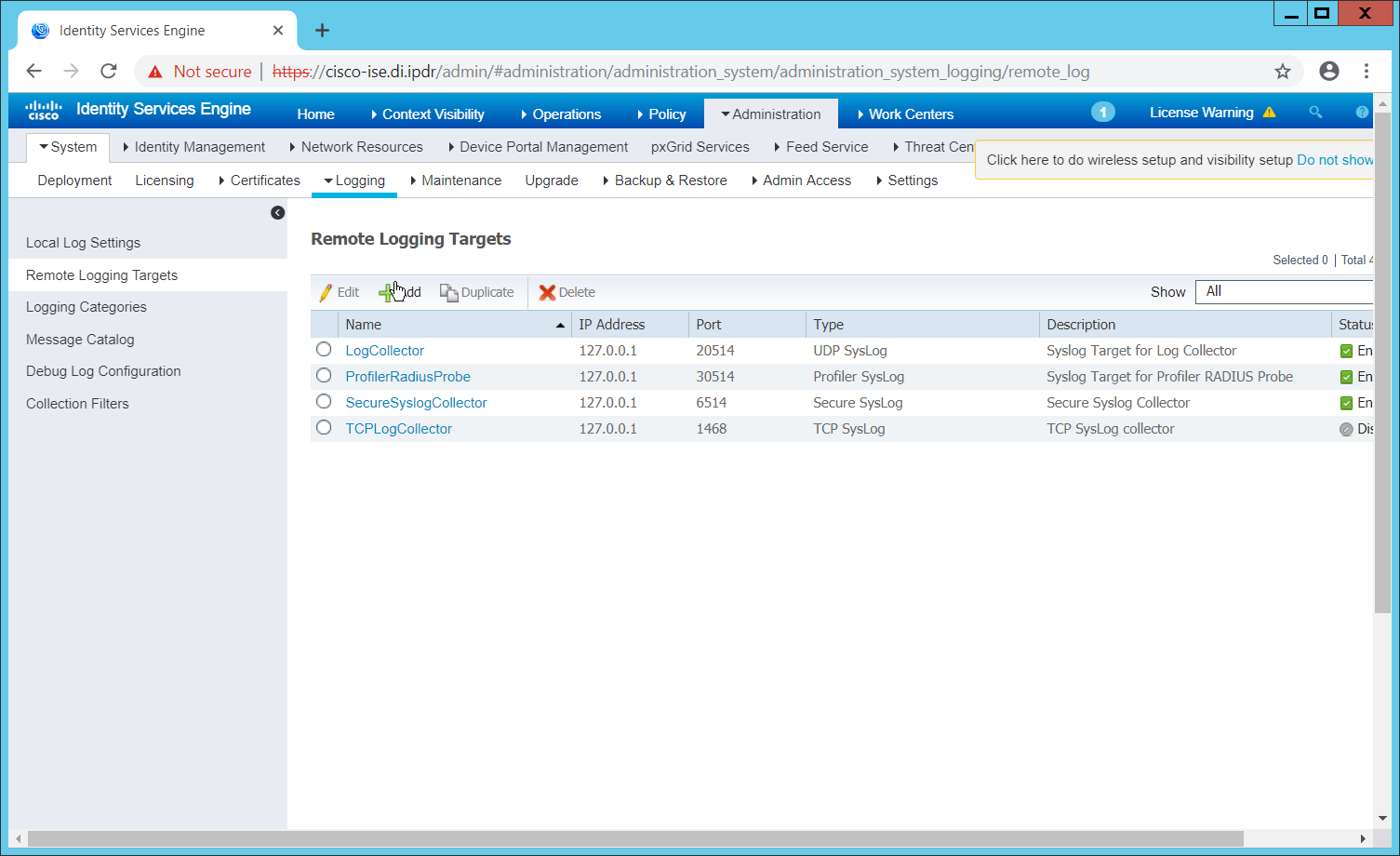
Click Add.
Enter a name for Name.
Enter the hostname of the ArcSight syslog collector server for Host/IP Address.
Select TCP SysLog for Target Type. (Ensure that your syslog collector server is configured to use TCP).
Enter 514 or the port used on the syslog server.
Enter 8192 or a custom message size limit for Maximum Length.
Ensure that Status is set to Enabled.
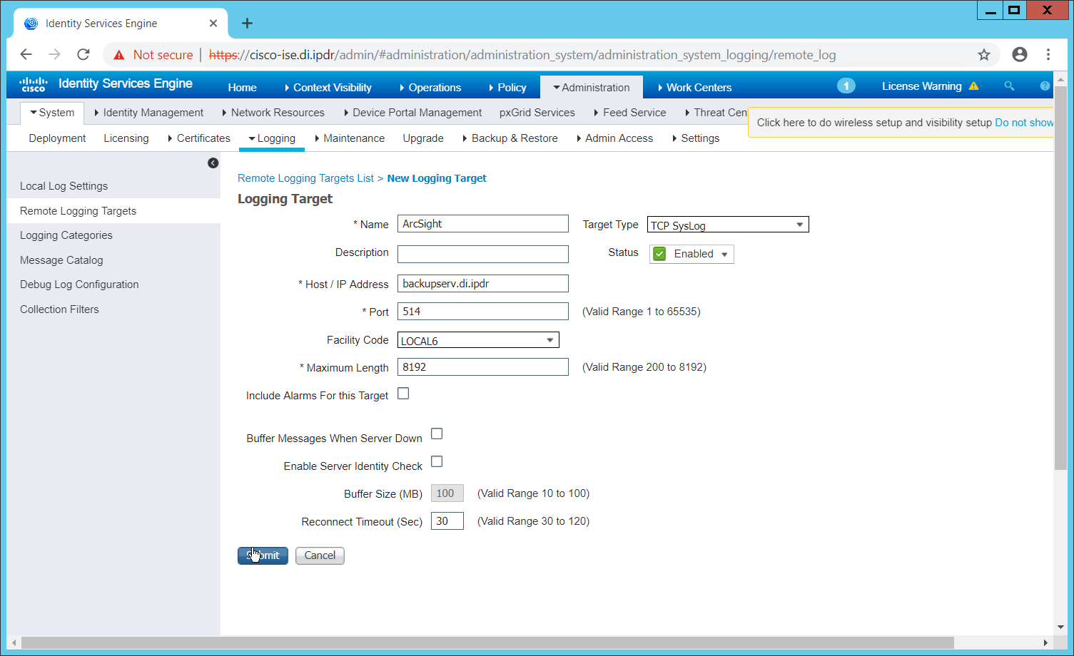
Click Submit.
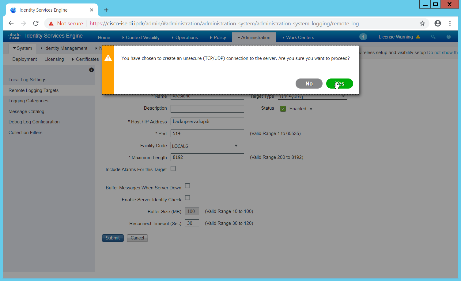
Click Yes.
2.21.2 Select Logs for Forwarding
Navigate to System > Logging > Logging Categories.
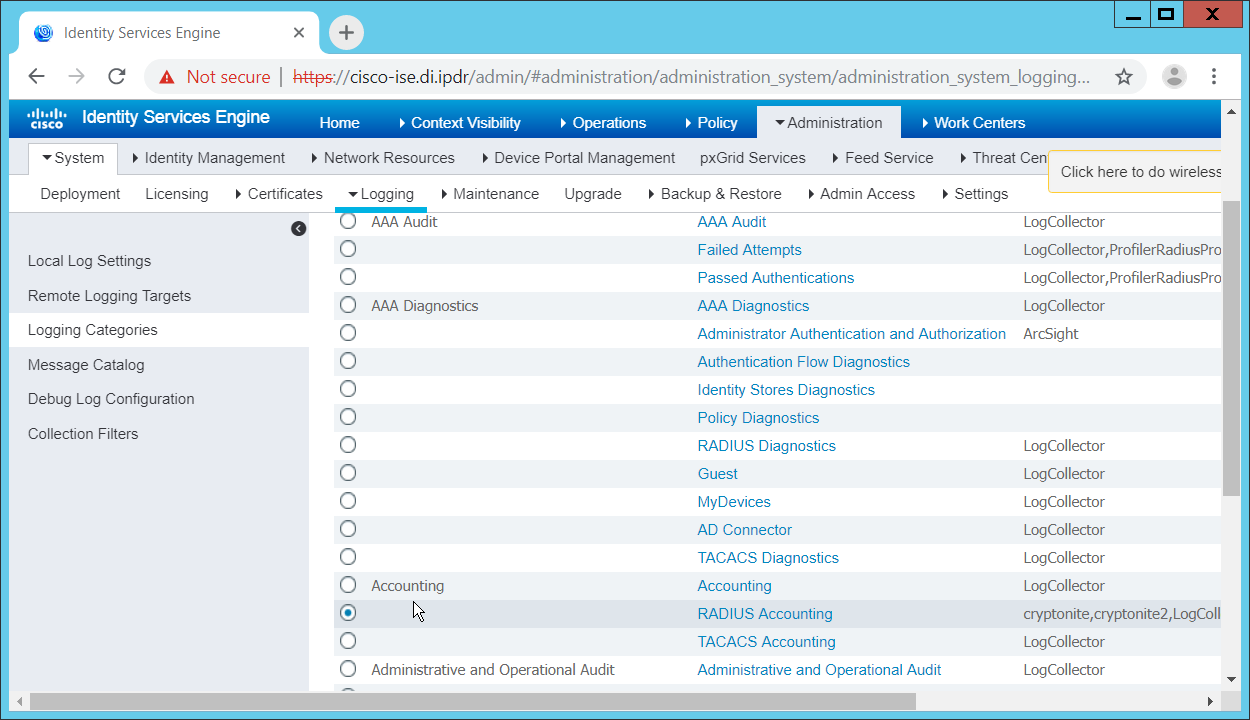
Select a log file to forward to ArcSight.
Click Edit.
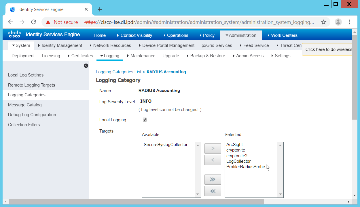
Move the ArcSight logging target you just created to the Selected box.
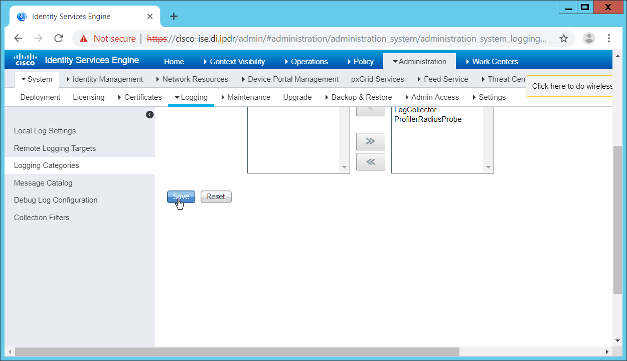
Click Save.
Repeat steps 1-5 for any log files you wish to forward to ArcSight.
2.22 Integration: Micro Focus ArcSight and Semperis DSP
This integration will briefly detail how to send logs to an ArcSight syslog collector from Semperis DSP. Please see Section 2.18 (under integrating Tripwire & ArcSight) for instructions for setting up an ArcSight syslog collector. If a server is already configured, you do not need to install a new one—use the address of that server to which to forward logs.
Note: This integration requires Semperis DSP version 2.6.
2.22.1 Configure Semperis DSP to Forward Logs
In Semperis DSP, navigate to Settings > SIEM Integration.
Check the box next to Enable SysLog.
Under Syslog Server, enter the hostname for the ArcSight syslog collector, as well as the port.
Select TCP.
Enter a value for Change Event Polling Frequency based on the needs of your organization; this is how often it will poll for new logs to forward.
Under Change Event Filtering, select AD Changed Items, and Send Operation Log to SysLog. Ensure that All is selected for Partitions.
You can also select any specific operations, classes, and attributes to be forwarded or leave it as All.
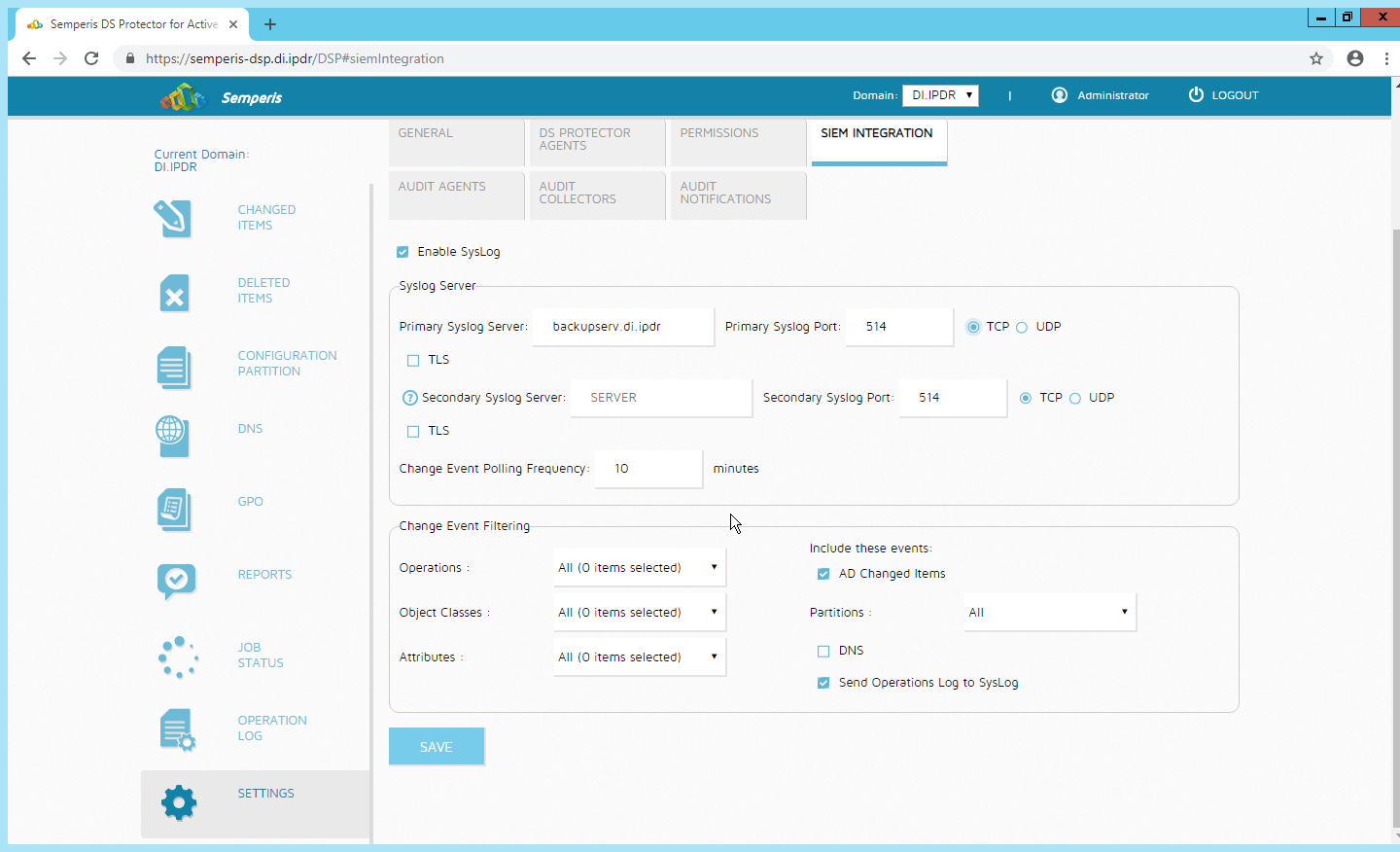
Click Save.
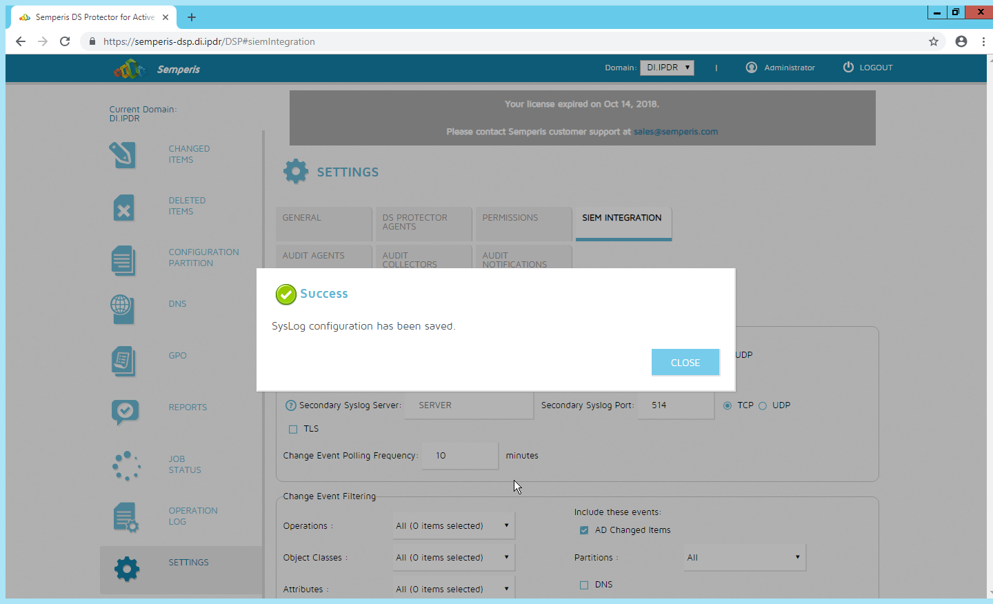
Click Close.
2.23 Integration: Micro Focus ArcSight and Symantec Analytics
This section will first detail the forwarding of logs from Symantec Analytics to Micro Focus ArcSight. Please see Section 2.18 (under integrating Tripwire & ArcSight) for instructions for setting up an ArcSight syslog collector. If a server is already configured, you do not need to install a new one; use the address of that server to which to forward logs.
The second part of this section will detail a further integration for ArcSight that allows ArcSight to better analyze network packets received from Symantec Analytics.
2.23.1 Configure Symantec Analytics to Forward Logs
Log in to the Symantec Analytics web console.
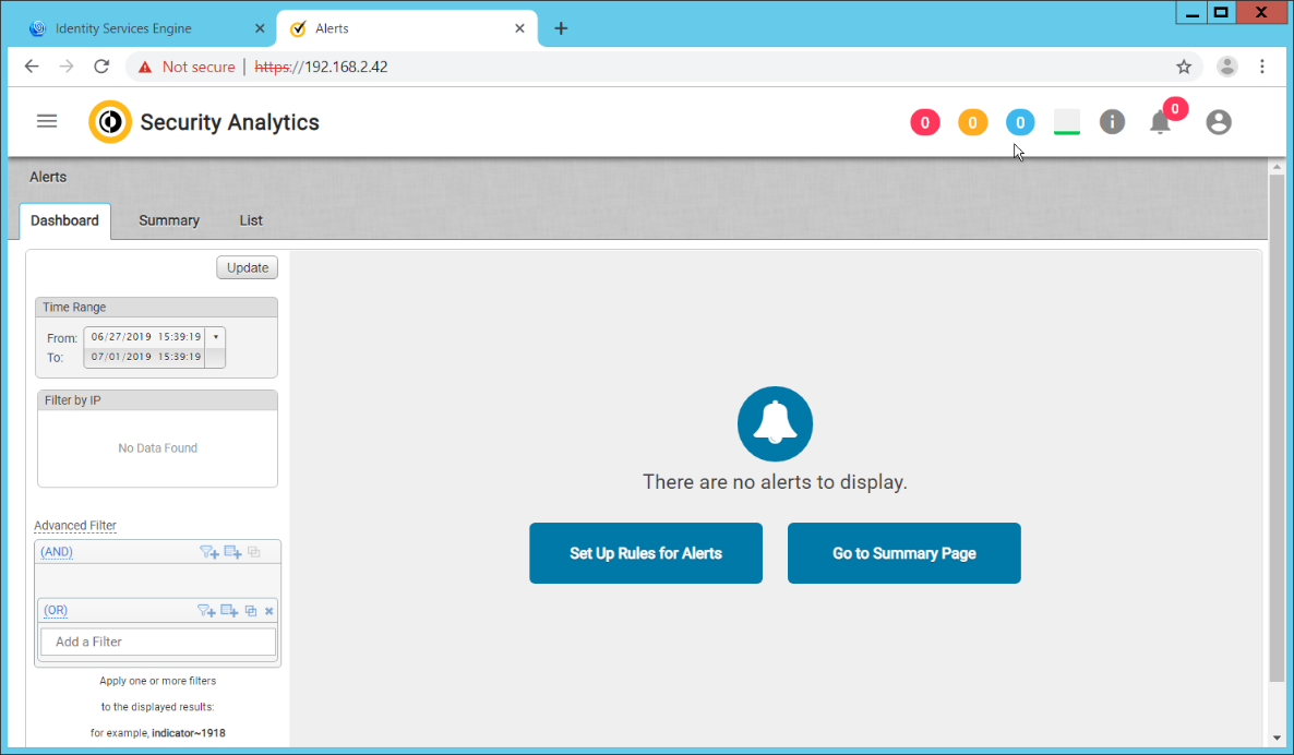
Click the menu icon in the top left.
Navigate to Settings > Communication.
Scroll down to the Syslog Settings section.
Select SysLog for Syslog Facility.
Enter the hostname or IP of the ArcSight syslog collector server under Server.
Enter 514 for the port.
Select TCP for the protocol.
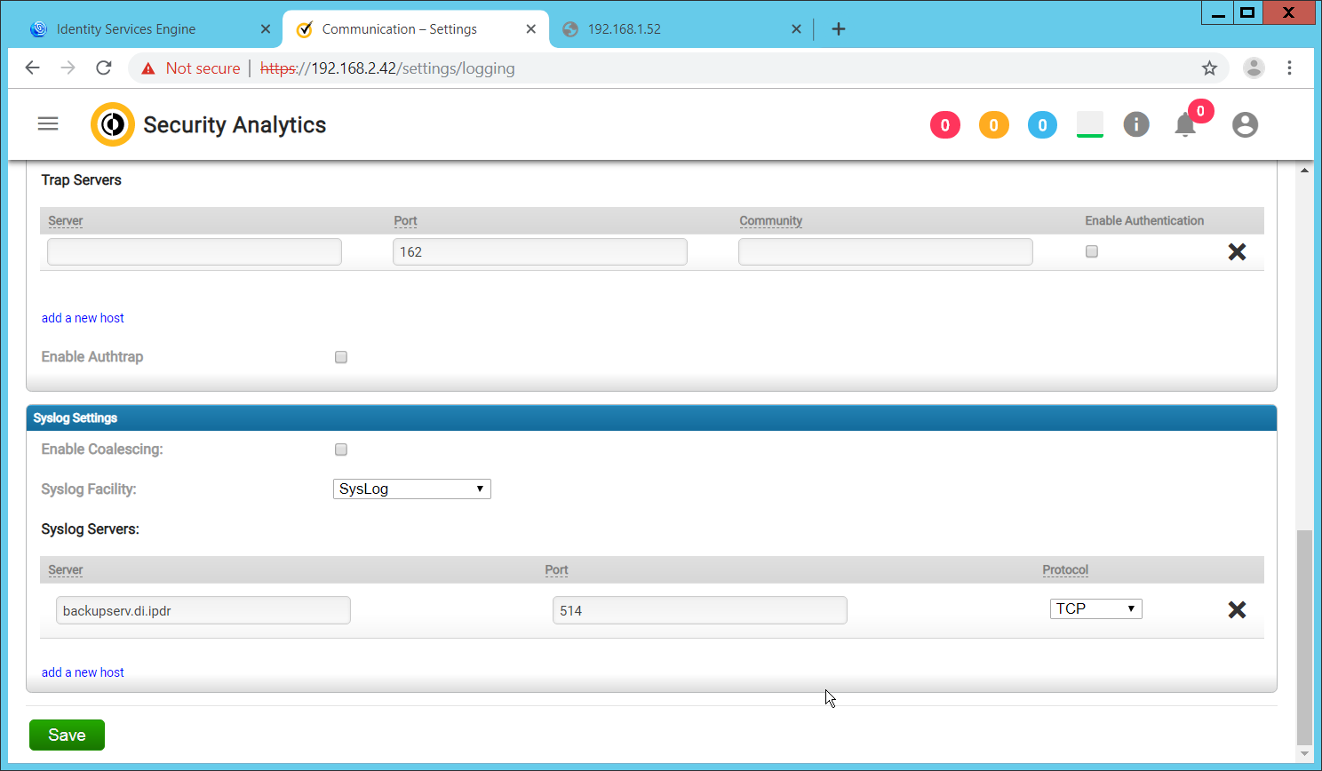
Click Save.
Click the Advanced tab.
Select the box under Remote Syslog column for any events that you wish to forward to ArcSight, for example, System Events, Unclassified Events, Alert Events, Rule Events, Anomaly Events.
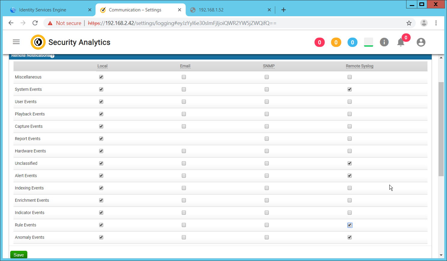
Click Save.
2.23.2 Install Symantec Analytics Package for ArcSight
Navigate to the ArcSight marketplace. Look for the “Blue Coat Security Analytics” package for ArcSight. It may be available here: https://marketplace.microfocus.com/arcsight/content/blue-coat-security-analytics-platform but if not please contact your ArcSight representative to get the package. The package should be called Blue_Coat_SA_HP_ArcSight-3.0.arb.
Place this package on a system with ArcSight ESM Console installed.
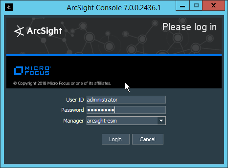
Log in to the ArcSight ESM Console with a user that has the privileges to install packages.
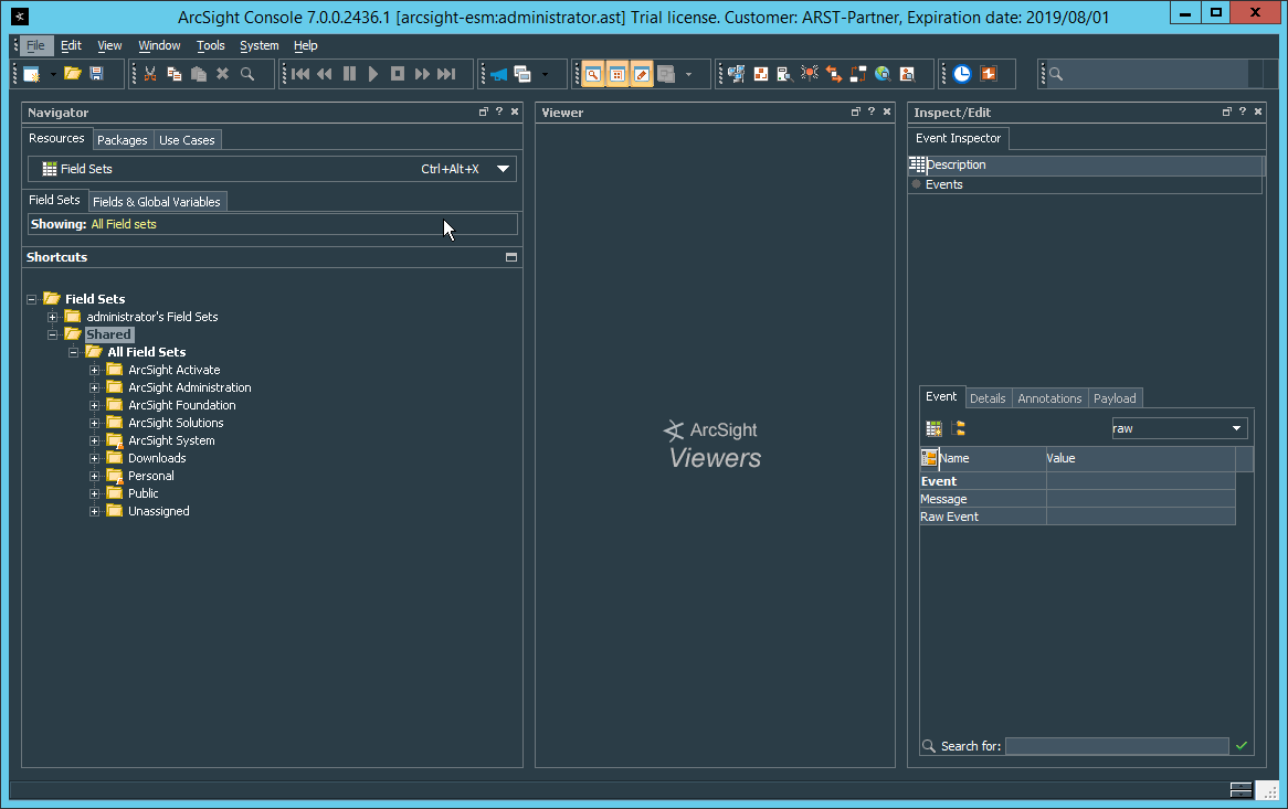
In the Navigator pane, click the Packages tab.
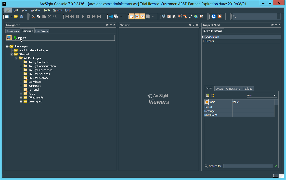
Click Import.
In the window that it opens, find and select the package you downloaded.
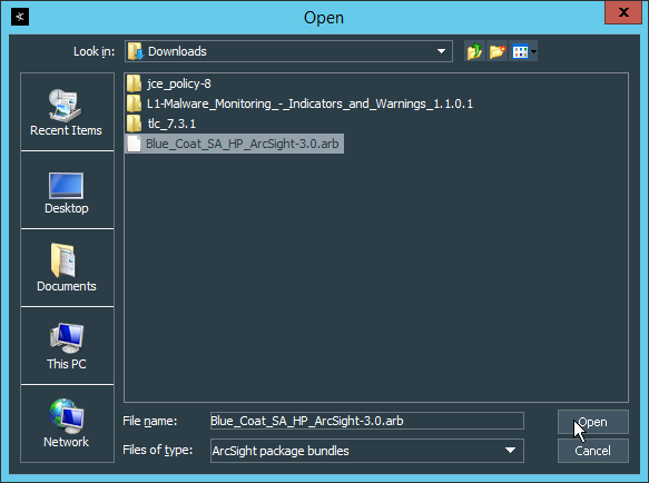
Click Open.
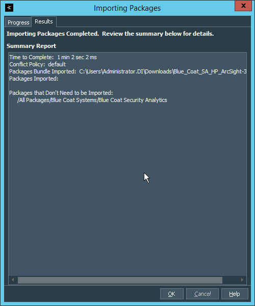
Click OK when the import finishes.
Under the Packages tab in the Navigator pane, navigate to Packages > Shared > All Packages > Blue Coat Systems > Blue Coat Security Analytics.
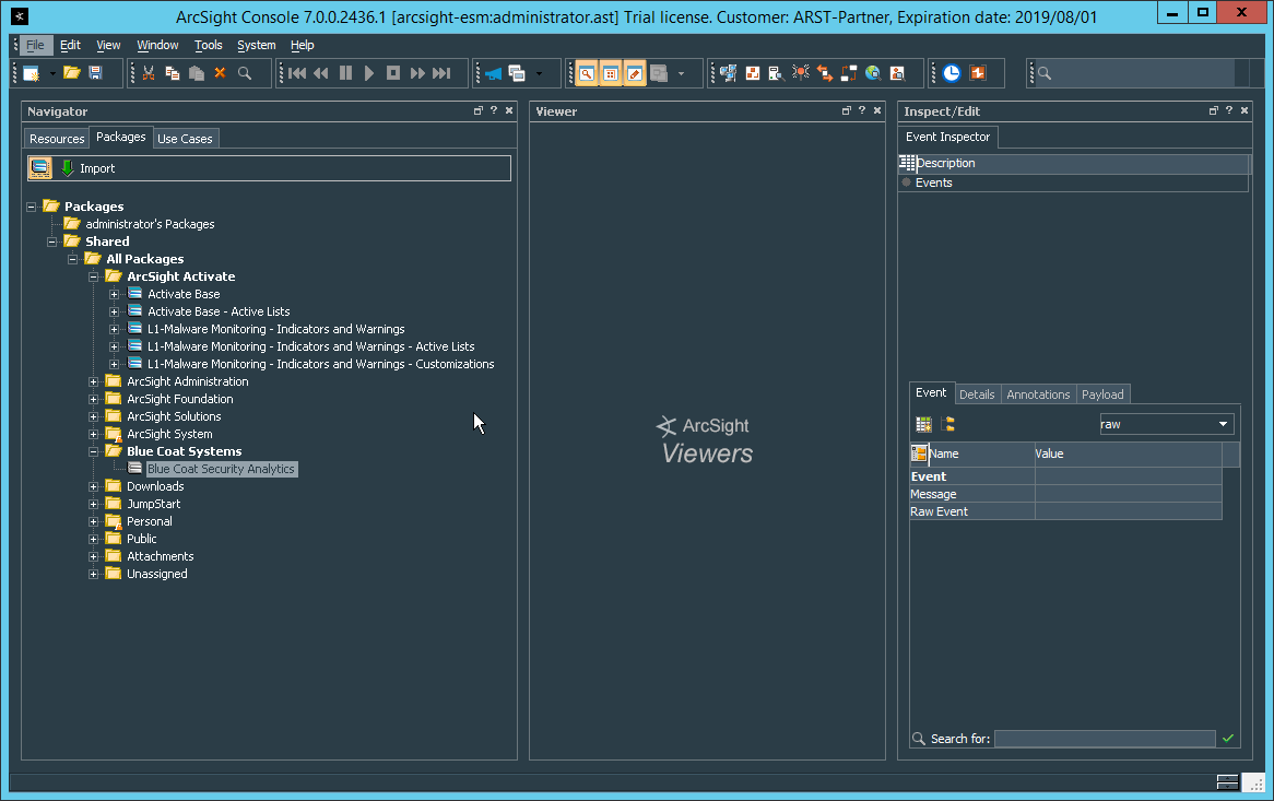
Right-click Blue Coat Security Analytics, and select Install Package.
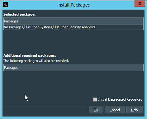
Click OK.
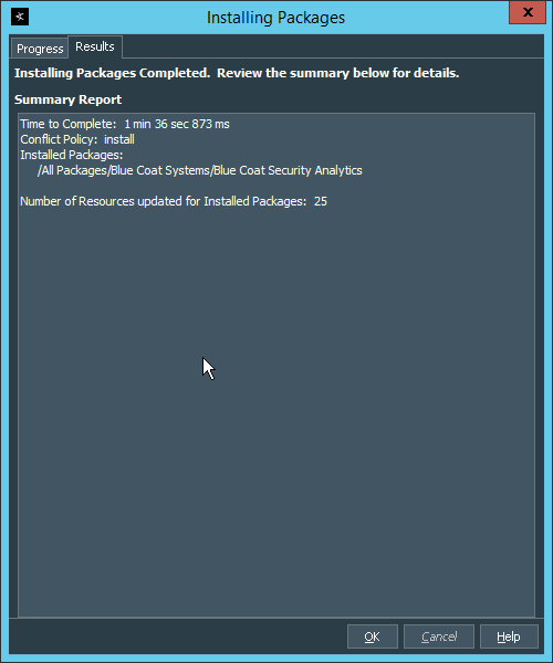
Click OK.
When this completes, you can verify that the installation was successful by the existence of a Blue Coat Systems folder when you navigate to Resources > Integration Commands > Commands > Shared > All Integration Commands.
In the Resources tab of the Navigation pane, under Integration Commands, select the Targets tab.
Navigate to Integration Targets > Shared > All Integration Targets > Blue Coat Systems > Blue Coat Security Analytic > Blue Coat Security Analytics.
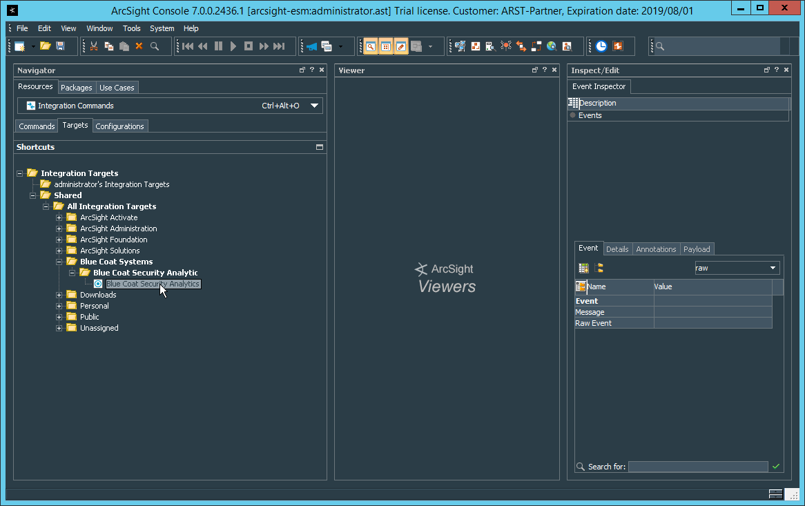
Right-click Blue Coat Security Analytics, and click Edit Target.
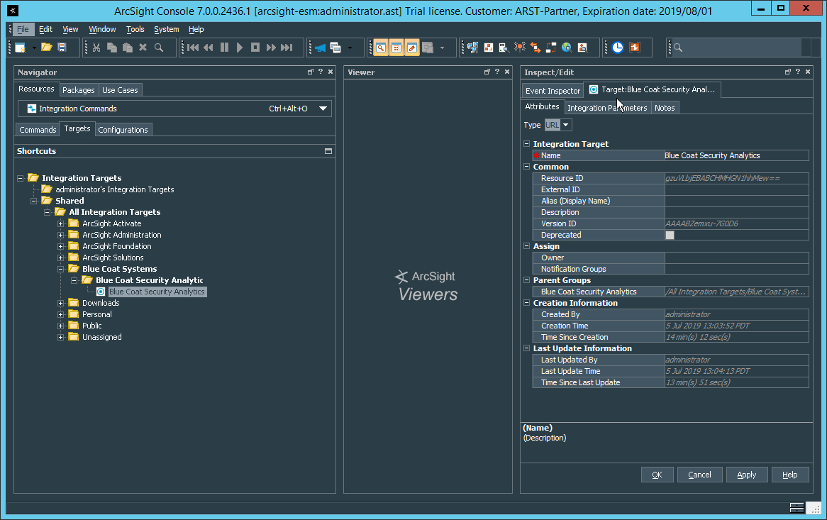
Click the Integration Parameters tab.
Replace the SAHost value with the IP address of Symantec Analytics.
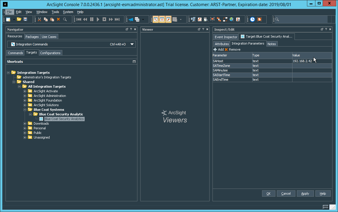
Click OK.
To verify the functionality, right-click an event in any channel, and select Integration Commands > Blue Coat Security Analytics.
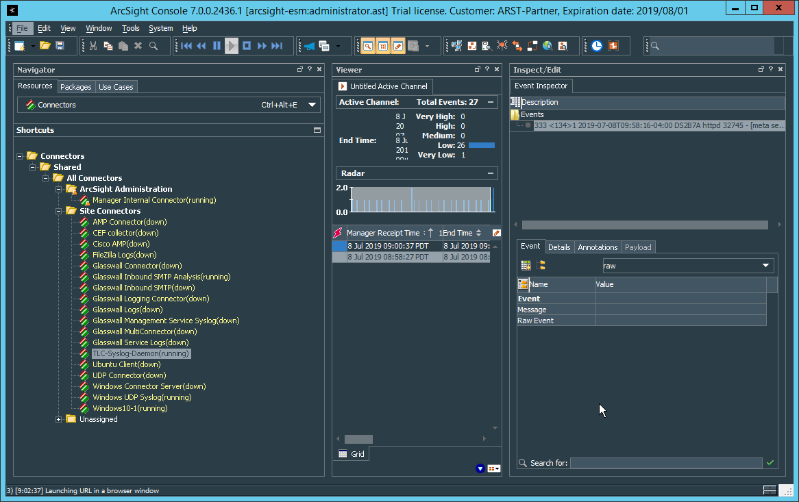
Select Security Analytics Investigation.
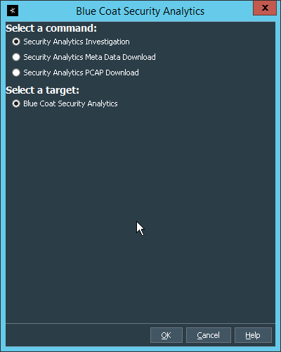
Click OK. This will open Security Analytics in the browser and perform a packet search based on the event parameters.
2.24 Integration: Micro Focus ArcSight and Glasswall FileTrust
Glasswall FileTrust for Email stores its logs in C:\Logging, on the server running the Glasswall services.
2.24.1 Install Micro Focus ArcSight
Run ArcSight-7.9.0.8084.0-Connector-Win64.exe on the same server as Glasswall FileTrust.
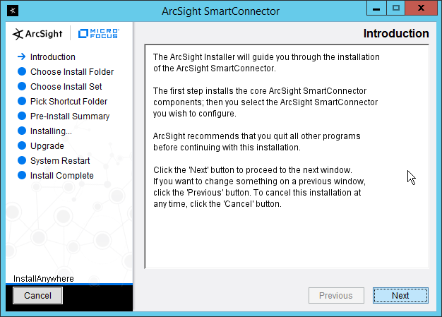
Click Next.
Enter C:\Program Files\ArcSightSmartConnectors\Windows.
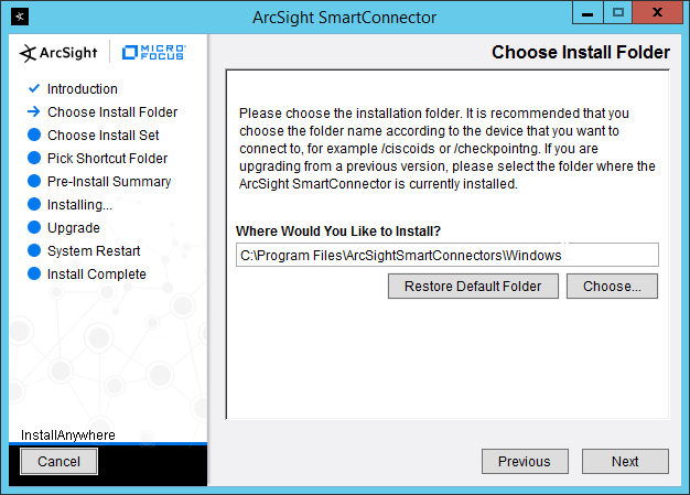
Click Next.

Click Next.
Click Install.
Select Add a Connector.
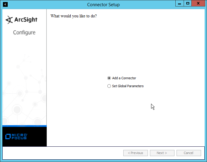
Click Next.
Select Syslog File.

Click Next.
Enter C:\Logging\gw-inbound-smtp-analysis-agent.current.log for File Absolute Path Name.
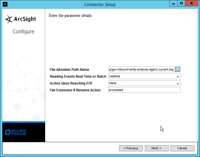
Click Next.
Select ArcSight Manager (encrypted).
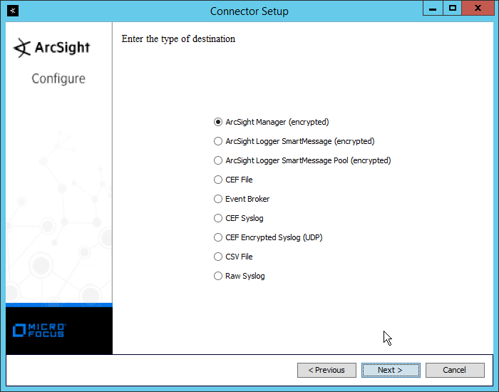
Click Next.
Enter the hostname, port, username, and password for the ArcSight ESM server.

Click Next.
Enter identifying details about the system (only Name is required).

Click Next.
Select Import the certificate to connector from destination.
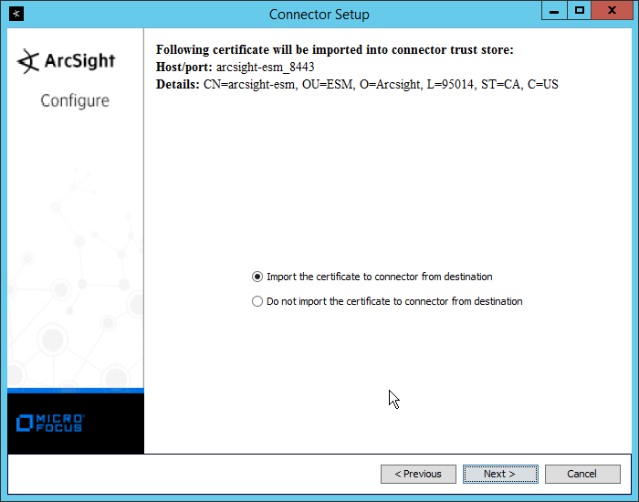
Click Next.

Click Next.
Select Install as a service.

Click Next.
Change the service parameters to more appropriate names, because multiple connectors need to be installed on this server.

Click Next.
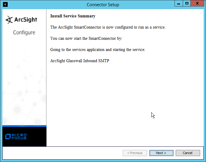
Click Next.
Select Exit.

Click Next.
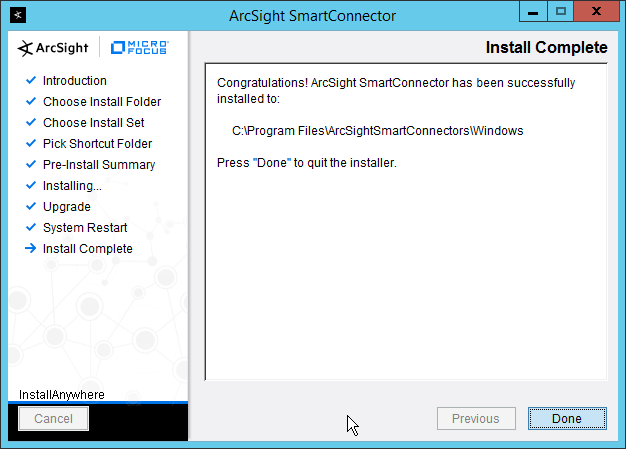
Click Done.
Repeat steps 1 to 29 for the other three “current” log files in C:\Logging, with the following caveats:
Replace C:\Program Files\ArcSightSmartConnectors\Windows with a different folder name for each connector.
Replace C:\Logging\gw-inbound-smtp-analysis-agent.current.log with the appropriate log file.
C:\Logging\gw-management-service.current.log
C:\Logging\gw-file-analysis-process-InboundSMTPAgent-0.current.log
C:\Logging\gw-administration-console.current.log
Replace the Name of the connector in its identifying details.
Replace the service parameters with different names so that the services do not conflict.
2.25 Integration: Micro Focus ArcSight and Cisco Stealthwatch
This section will detail the forwarding of logs from Cisco Stealthwatch to Micro Focus ArcSight.
2.25.1 Install Micro Focus ArcSight
Run ArcSight-7.9.0.8084.0-Connector-Win64.exe on any server except the one running Cisco Stealthwatch.
Click Next.
Enter C:\Program Files\ArcSightSmartConnectors\WindowsUDP.
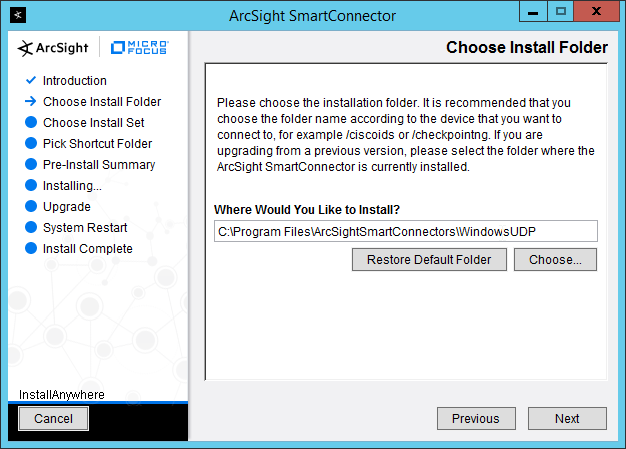
Click Next.
Click Next.
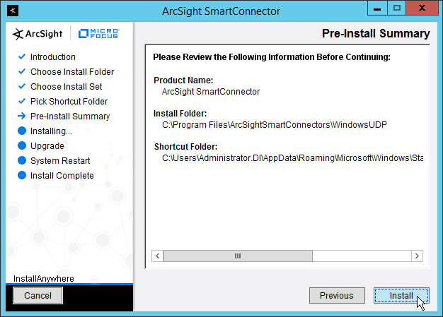
Click Install.
Select Add a Connector.
Click Next.
Select Syslog Daemon.

Click Next.
Enter an unused port for the daemon to run on. (Ensure that this port is allowed through the firewall.)
Select UDP for Protocol.

Click Next.
Select ArcSight Manager (encrypted).
Click Next.
Enter the hostname, port, username, and password for the ArcSight ESM server.
Click Next.
Enter identifying details about the system (only Name is required).

Click Next.
Select Import the certificate to connector from destination.
Click Next.
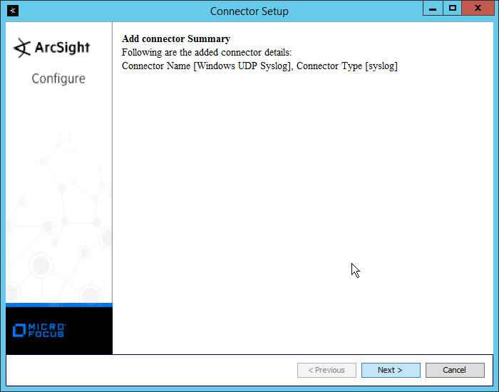
Click Next.
Select Install as a service.
Click Next.
Enter a service name and display name.
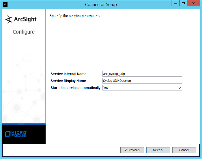
Click Next.
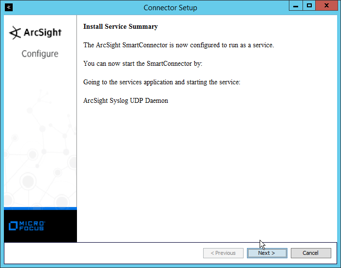
Click Next.
Select Exit.
Click Next.
Click Done.
2.25.2 Configure Cisco Stealthwatch
Log in to the Cisco Stealthwatch Management Console desktop interface. (This can be downloaded from the web interface and run using javaws.exe. You may need to add the site to your Java exceptions in Control Panel > Java.)
Click Configuration > Response Management.
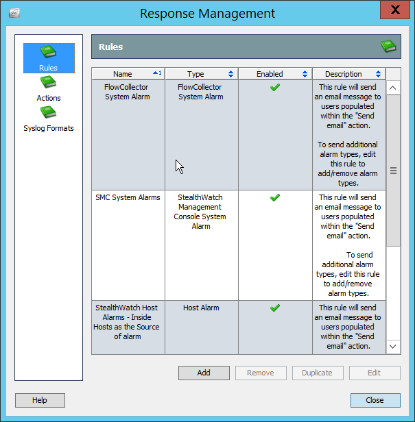
Click Actions.
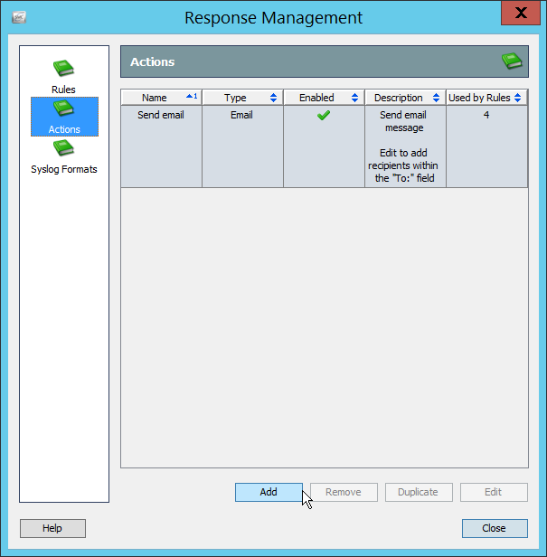
Click Add.
Select ArcSight Common Event Format (CEF).
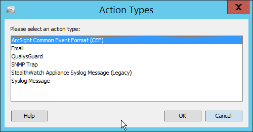
Click OK.
Enter a name for the Action.
Enter a description.
Enter the IP address of the server with the User Datagram Protocol (UDP) ArcSight Connector that you just created.
Enter the port used in the UDP ArcSight Connector that you just created.
(Optional) Click Test to send a test message to ArcSight, and verify that ArcSight receives the message.
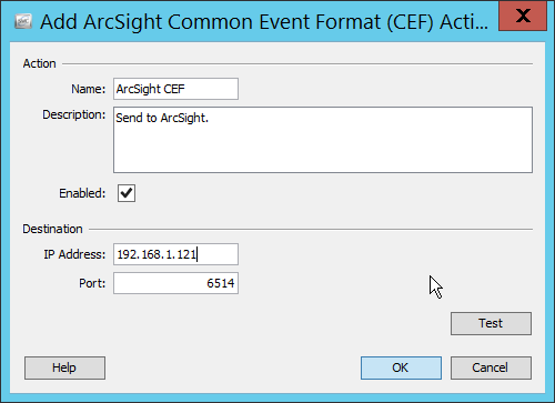
Click OK.
Verify that the action was created properly.
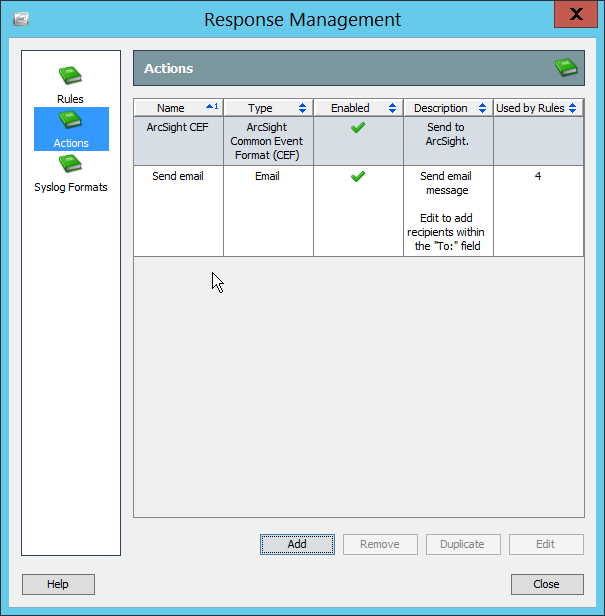
Click Rules.

Click Add.
Select Host Alarm.
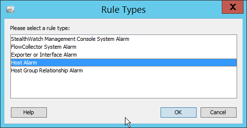
Click OK.
Enter a name.
Enter a description.
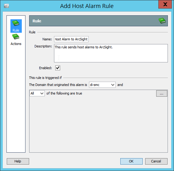
Click Actions.
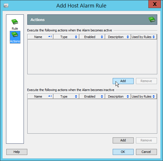
Click the Add button for the top section; this adds an action when the alarm becomes active.
Select the ArcSight CEF rule you just created.
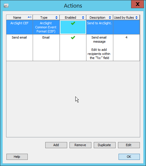
Click OK.
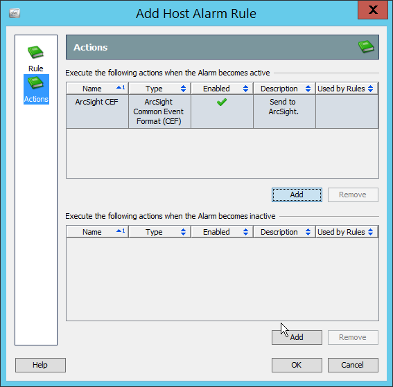
Click the Add button for the bottom section; this adds an action when the alarm becomes inactive.
Select the ArcSight CEF rule you just created.
Click OK.
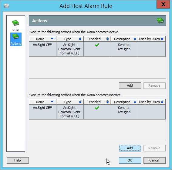
Click OK.
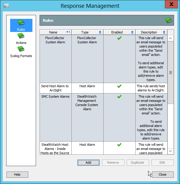
Click Close.