NIST SPECIAL PUBLICATION 1800-25C
Data Integrity:
Identifying and Protecting Assets Against Ransomware and Other Destructive Events
Volume C:
How-to Guides
Jennifer Cawthra
National Cybersecurity Center of Excellence
NIST
Michael Ekstrom
Lauren Lusty
Julian Sexton
John Sweetnam
The MITRE Corporation
McLean, Virginia
December 2020
FINAL
This publication is available free of charge from https://www.nccoe.nist.gov/projects/building-blocks/data-integrity/identify-protect.

DISCLAIMER
Certain commercial entities, equipment, products, or materials may be identified by name or company logo or other insignia in order to acknowledge their participation in this collaboration or to describe an experimental procedure or concept adequately. Such identification is not intended to imply special status or relationship with NIST or recommendation or endorsement by NIST or NCCoE; neither is it intended to imply that the entities, equipment, products, or materials are necessarily the best available for the purpose.
National Institute of Standards and Technology Special Publication 1800-25C, Natl. Inst. Stand. Technol. Spec. Publ. 1800-25C, 489 pages, (December 2020), CODEN: NSPUE2
FEEDBACK
As a private-public partnership, we are always seeking feedback on our practice guides. We are particularly interested in seeing how businesses apply NCCoE reference designs in the real world. If you have implemented the reference design, or have questions about applying it in your environment, please email us at ds-nccoe@nist.gov.
All comments are subject to release under the Freedom of Information Act.
NATIONAL CYBERSECURITY CENTER OF EXCELLENCE
The National Cybersecurity Center of Excellence (NCCoE), a part of the National Institute of Standards and Technology (NIST), is a collaborative hub where industry organizations, government agencies, and academic institutions work together to address businesses’ most pressing cybersecurity issues. This public-private partnership enables the creation of practical cybersecurity solutions for specific industries, as well as for broad, cross-sector technology challenges. Through consortia under Cooperative Research and Development Agreements (CRADAs), including technology partners—from Fortune 50 market leaders to smaller companies specializing in information technology security—the NCCoE applies standards and best practices to develop modular, adaptable example cybersecurity solutions using commercially available technology. The NCCoE documents these example solutions in the NIST Special Publication 1800 series, which maps capabilities to the NIST Cybersecurity Framework and details the steps needed for another entity to re-create the example solution. The NCCoE was established in 2012 by NIST in partnership with the State of Maryland and Montgomery County, Maryland.
NIST CYBERSECURITY PRACTICE GUIDES
NIST Cybersecurity Practice Guides (Special Publication 1800 series) target specific cybersecurity challenges in the public and private sectors. They are practical, user-friendly guides that facilitate the adoption of standards-based approaches to cybersecurity. They show members of the information security community how to implement example solutions that help them align with relevant standards and best practices, and provide users with the materials lists, configuration files, and other information they need to implement a similar approach.
The documents in this series describe example implementations of cybersecurity practices that businesses and other organizations may voluntarily adopt. These documents do not describe regulations or mandatory practices, nor do they carry statutory authority.
ABSTRACT
Ransomware, destructive malware, insider threats, and even honest user mistakes present ongoing threats to organizations. Organizations’ data, such as database records, system files, configurations, user files, applications, and customer data, are all potential targets of data corruption, modification, and destruction. Formulating a defense against these threats requires two things: a thorough knowledge of the assets within the enterprise, and the protection of these assets against the threat of data corruption and destruction. The NCCoE, in collaboration with members of the business community and vendors of cybersecurity solutions, has built an example solution to address these data integrity challenges.
Multiple systems need to work together to identify and protect an organization’s assets against the threat of corruption, modification, and destruction. This project explores methods to effectively identify assets (devices, data, and applications) that may become targets of data integrity attacks, as well as the vulnerabilities in the organization’s system that facilitate these attacks. It also explores methods to protect these assets against data integrity attacks using backups, secure storage, integrity checking mechanisms, audit logs, vulnerability management, maintenance, and other potential solutions.
KEYWORDS
attack vector; asset awareness; data integrity; data protection; malicious actor; malware; ransomware.
ACKNOWLEDGMENTS
We are grateful to the following individuals for their generous contributions of expertise and time.
Name |
Organization |
|---|---|
Kyle Black |
Bay Dynamics |
Sunjeet Randhawa |
Broadcom Inc. |
Peter Romness |
Cisco Systems |
Matthew Hyatt |
Cisco Systems |
Hans Ismirnioglou |
Cryptonite |
Sapna George |
Cryptonite |
Justin Yackoski |
Cryptonite |
Steve Petruzzo |
GreenTec USA |
Steve Roberts |
Micro Focus |
Timothy McBride |
NIST |
Christopher Lowde |
Semperis |
Thomas Leduc |
Semperis |
Darren Mar-Elia |
Semperis |
Kirk Lashbrook |
Semperis |
Mickey Bresman |
Semperis |
Jim Wachhaus |
Tripwire |
Humphrey Christian |
Symantec Corporation |
Jon Christmas |
Symantec Corporation |
Kenneth Durbin |
Symantec Corporation |
Matthew Giblin |
Symantec Corporation |
Nancy Correll |
The MITRE Corporation |
Chelsea Deane |
The MITRE Corporation |
Sallie Edwards |
The MITRE Corporation |
Milissa McGinnis |
The MITRE Corporation |
Karri Meldorf |
The MITRE Corporation |
Denise Schiavone |
The MITRE Corporation |
Anne Townsend |
The MITRE Corporation |
The Technology Partners/Collaborators who participated in this build submitted their capabilities in response to a notice in the Federal Register. Respondents with relevant capabilities or product components were invited to sign a Cooperative Research and Development Agreement (CRADA) with NIST, allowing them to participate in a consortium to build this example solution. We worked with:
Technology Partner/Collaborator |
Build Involvement |
|---|---|
Symantec Corporation |
Symantec Data Loss Prevention v15.1 |
Cisco Systems |
Cisco ISE v2.4, Cisco Web Security Appliance v10.1 |
GreenTec USA |
GreenTec WORMdisk v151228 |
Tripwire |
Tripwire Log Center v7.3.1, Tripwire Enterprise v8.7, Tripwire IP360 v9.0.1 |
Micro Focus |
Micro Focus ArcSight Enterprise Security Manager v7.0 Patch 2 |
Cryptonite |
CryptoniteNXT v2.9.1 |
Semperis |
Semperis Active Directory Forest Recovery v2.5, Semperis Directory Services Protector v2.7 |
1 Introduction
The following volumes of this guide show information technology (IT) professionals and security engineers how we implemented this example solution. We cover all of the products employed in this reference design. We do not re-create the product manufacturers’ documentation, which is presumed to be widely available. Rather, these volumes show how we incorporated the products together in our environment.
Note: These are not comprehensive tutorials. There are many possible service and security configurations for these products that are out of scope for this reference design.
1.1 How to Use this Guide
This National Institute of Standards and Technology (NIST) Cybersecurity Practice Guide demonstrates a standards-based reference design and provides users with the information they need to replicate the data integrity identify-and protect-solution. This reference design is modular and can be deployed in whole or in part.
This guide contains three volumes:
NIST SP 1800-25A: Executive Summary
NIST SP 1800-25B: Approach, Architecture, and Security Characteristics – what we built and why
NIST SP 1800-25C: How-To Guides – instructions for building the example solution (you are here)
Depending on your role in your organization, you might use this guide in different ways:
Business decision makers, including chief security and technology officers, will be interested in the Executive Summary (NIST SP 1800-25A), which describes the following topics:
challenges that enterprises face in identifying assets and protecting them from data integrity events
example solution built at the NCCoE
benefits of adopting the example solution
Technology or security program managers who are concerned with how to identify, understand, assess, and mitigate risk will be interested in NIST SP 1800-25B, which describes what we did and why. The following sections will be of particular interest:
Section 3.4.1 , Risk, provides a description of the risk analysis we performed.
Section 3.4.2 , Security Control Map , maps the security characteristics of this example solution to cybersecurity standards and best practices.
You might share the Executive Summary, NIST SP 1800-25A, with your leadership team members to help them understand the importance of adopting standards-based data integrity solutions.
IT professionals who want to implement an approach like this will find the whole practice guide useful. You can use this How-To portion of the guide, NIST SP 1800-25C, to replicate all or parts of the build created in our lab. This How-To portion of the guide provides specific product installation, configuration, and integration instructions for implementing the example solution. We do not recreate the product manufacturers’ documentation, which is generally widely available. Rather, we show how we incorporated the products together in our environment to create an example solution.
This guide assumes that IT professionals have experience implementing security products within the enterprise. While we have used a suite of commercial products to address this challenge, this guide does not endorse these particular products. Your organization can adopt this solution or one that adheres to these guidelines in whole, or you can use this guide as a starting point for tailoring and implementing parts of a data integrity identify-and-protect solution. Your organization’s security experts should identify the products that will best integrate with your existing tools and IT system infrastructure. We hope that you will seek products that are congruent with applicable standards and best practices. Section 3.5 of Volume B, Technologies, lists the products we used and maps them to the cybersecurity controls provided by this reference solution.
A NIST Cybersecurity Practice Guide does not describe “the” solution, but a possible solution. This is a draft guide. We seek feedback on its contents and welcome your input. Comments, suggestions, and success stories will improve subsequent versions of this guide. Please contribute your thoughts to ds-nccoe@nist.gov.
1.2 Build Overview
The National Cybersecurity Center of Excellence (NCCoE) built a hybrid virtual-physical laboratory environment to explore methods to effectively identify assets and protect them against a data corruption event in various IT enterprise environments. The NCCoE also explored identifying vulnerabilities in advance of an incident. The servers in the virtual environment were built to the hardware specifications of their specific software components.
The NCCoE worked with members of the Data Integrity Community of Interest to develop a diverse but noncomprehensive set of use case scenarios against which to test the reference implementation. These are detailed in Volume B, Section 5.2. For a detailed description of our architecture, see Volume B, Section 4.
1.3 Typographic Conventions
The following table presents typographic conventions used in this volume.
Typeface/Symbol |
Meaning |
Example |
|---|---|---|
Italics |
file names and pathnames; references to documents that are not hyperlinks; new terms; and placeholders |
For language use and style guidance, see the NCCoE Style Guide. |
Bold |
names of menus, options, command buttons, and fields |
Choose File > Edit. |
|
command-line input, onscreen computer output, sample code examples, and status codes |
mkdir |
blue text |
link to other parts of the document, a web URL, or an email address |
All publications from NIST’s NCCoE are available at https://nccoe.nist.gov. |
2 Product Installation Guides
This section of the practice guide contains detailed instructions for installing and configuring all of the products used to build an instance of the example solution.
2.1 Active Directory and Domain Name System (DNS Server)
As part of our enterprise emulation, we included an Active Directory server that doubles as a DNS server. This section covers the installation and configuration process used to set up Active Directory and DNS on a Windows Server 2012 R2 machine.
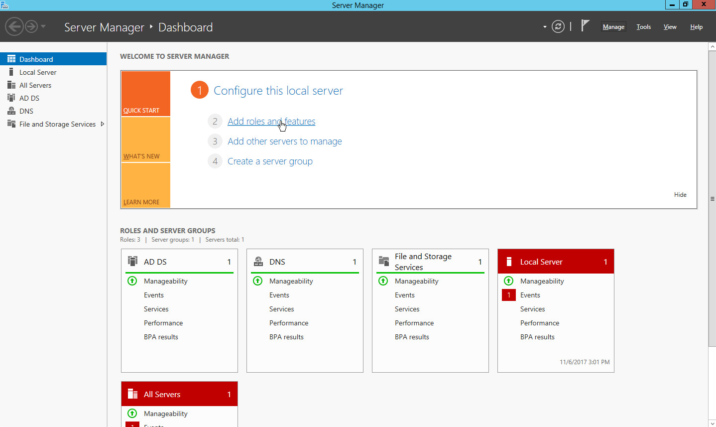
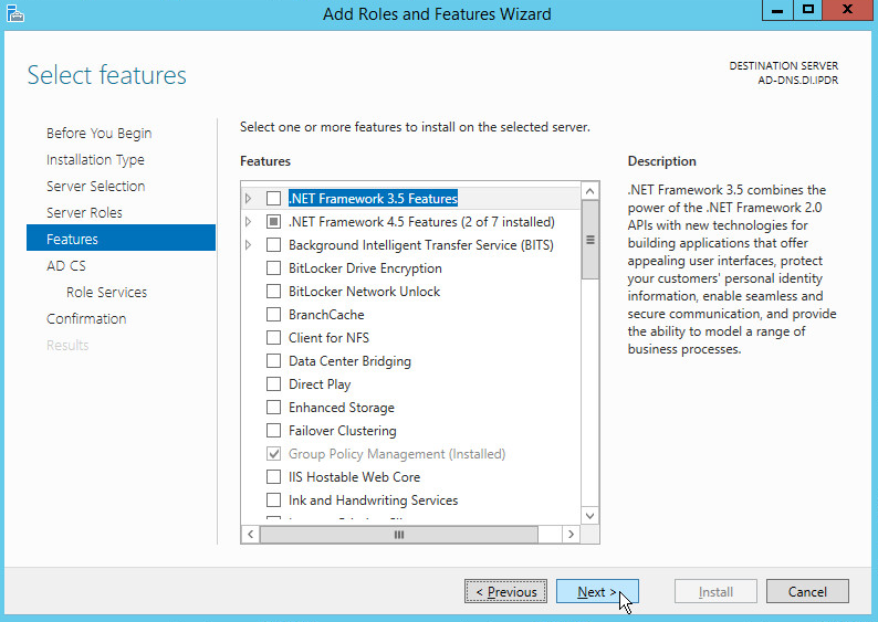
2.1.1 Installing Features
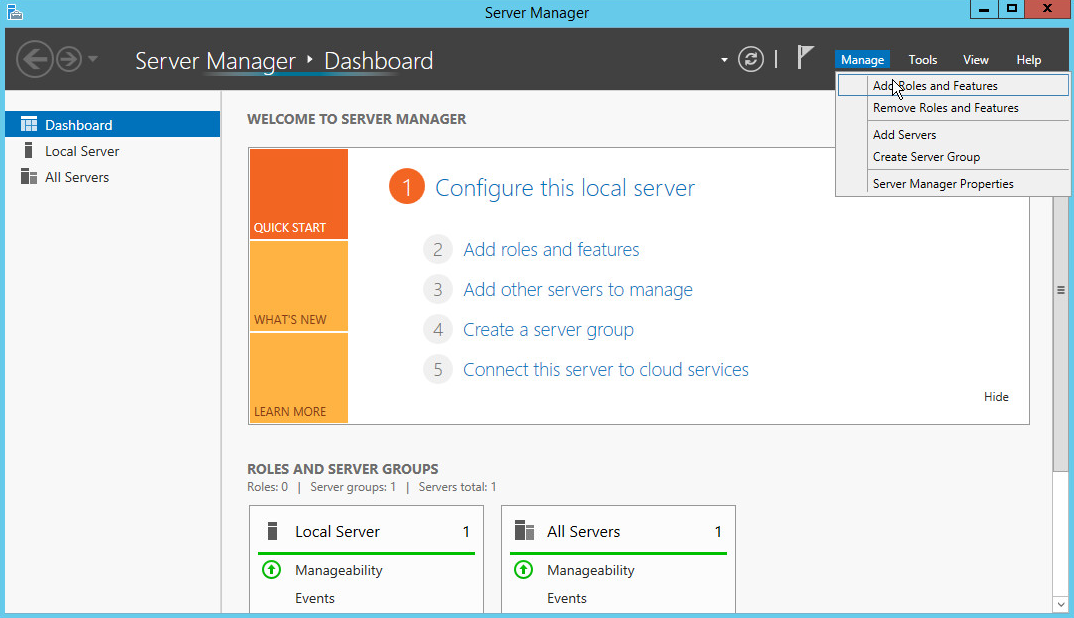
Open Server Manager.
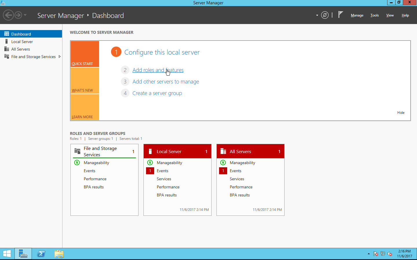
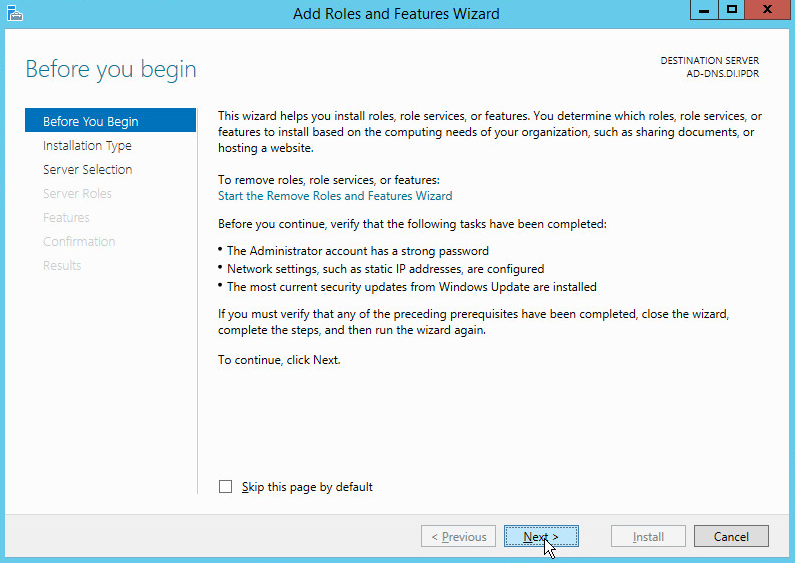
Click the link Add roles and features.

Click Next.
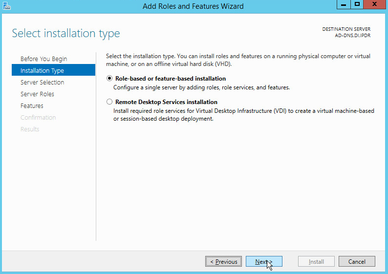
Select Role-based or feature-based installation.

Click Next.
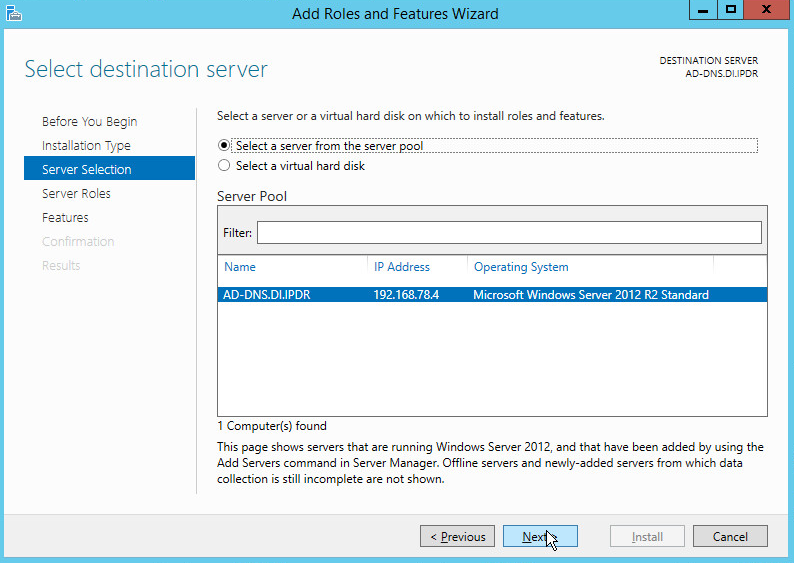
Select Select a server from the server pool.
Select the intended Active Directory server.
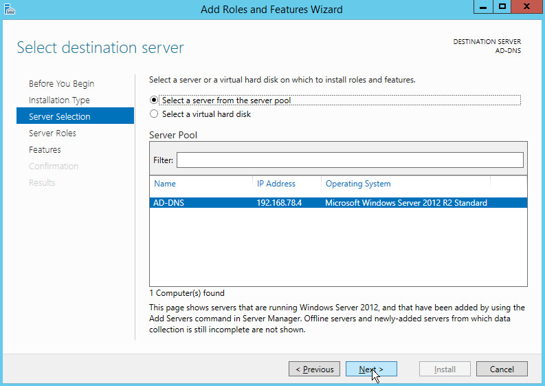
Click Next.
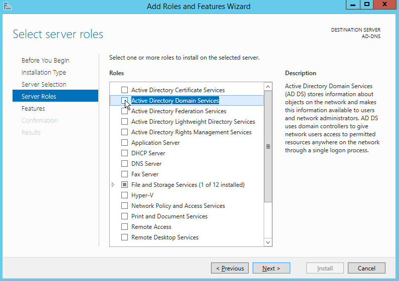
Check the box next to Active Directory Domain Services.
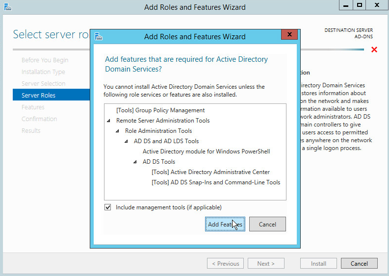
Click Add Features.
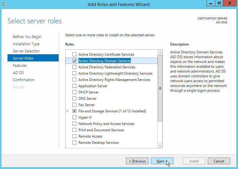
Click Next.
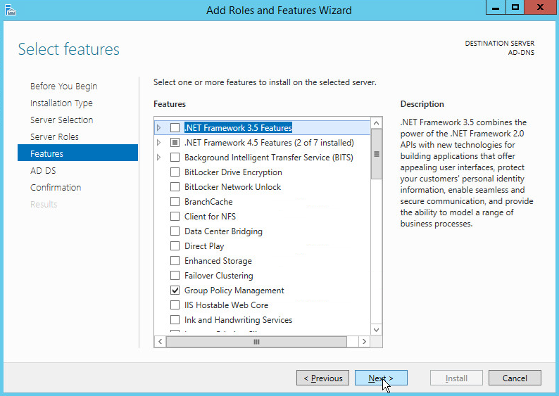
Click Next.
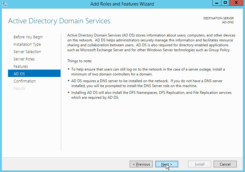
Click Next.
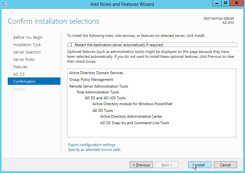
Click Install.
Wait for the installation to complete.
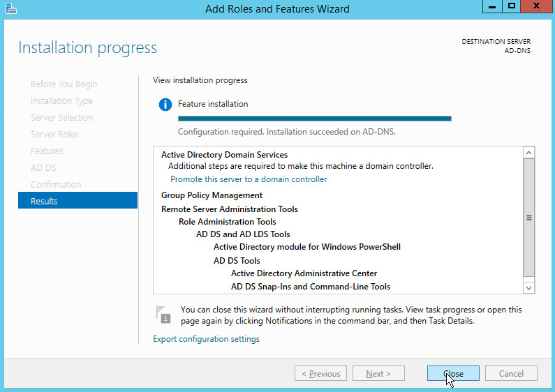
Click Close.
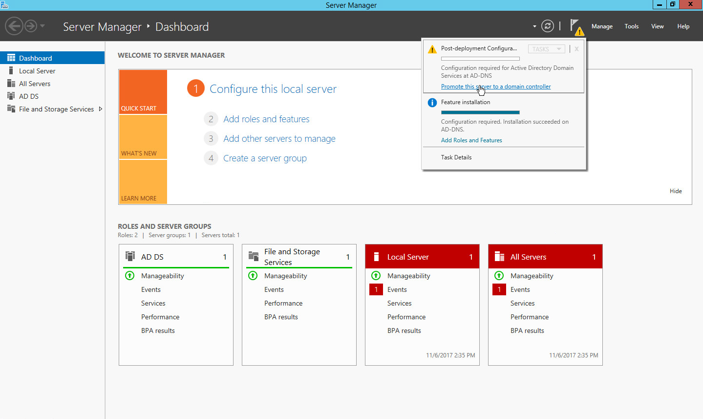
Click Promote this server to a domain controller.
Select Add a new forest.
Enter a Root domain name.
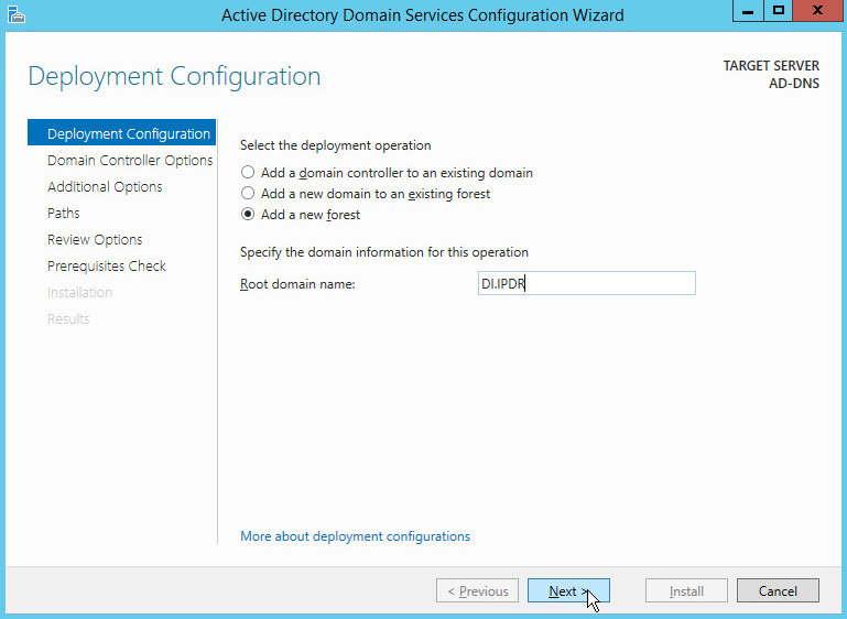
Click Next.
Select Windows Server 2012 R2 for Forest functional level and Domain functional level.
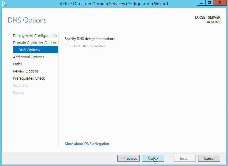
Check the box next to Domain Name System (DNS) server.
Enter a password.
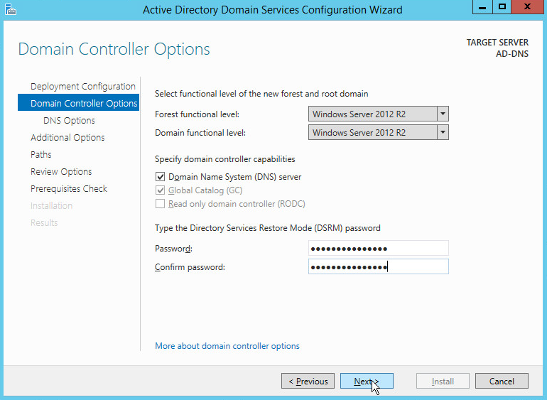
Click Next.
Click Next.
Verify the domain name.
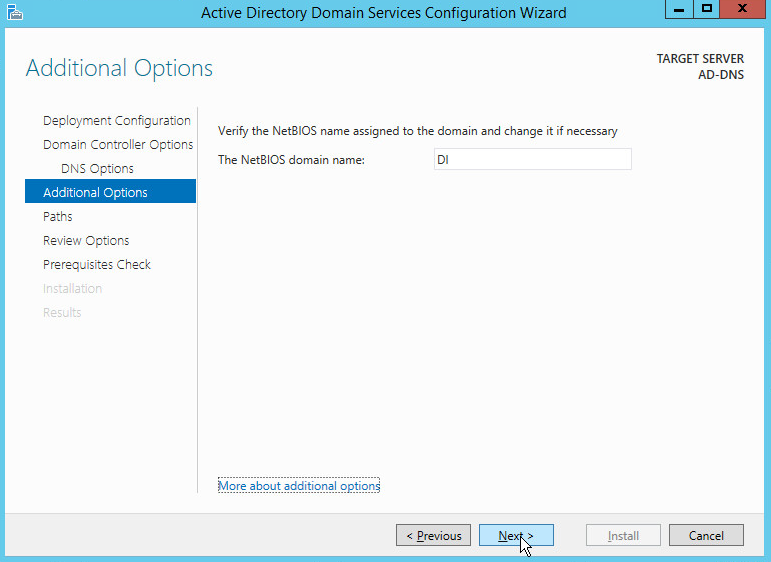
Click Next.
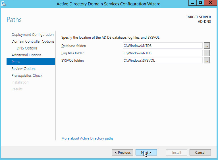
Click Next.
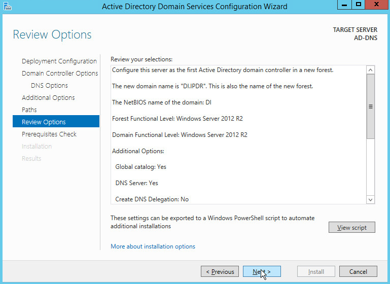
Click Next.
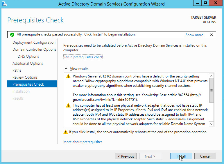
Click Install.
Wait for the installation to complete.
The server automatically reboots.
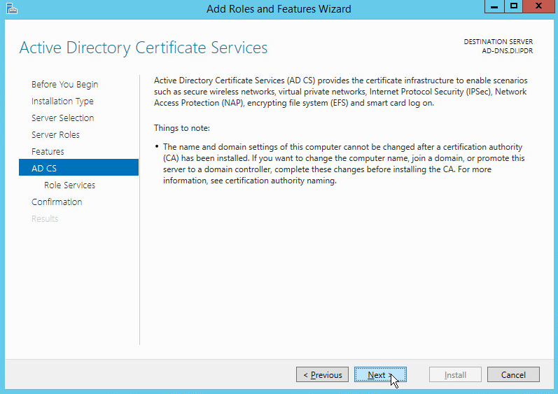
2.1.2 Creating a Certificate Authority
Open Server Manager.
Click Add roles and features.
Click Next.
Select Role-based or feature-based installation.
Click Next.
Select Select a server from the server pool.
Select the intended Active Directory server.
Click Next.
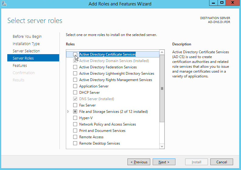
Check the box next to Active Directory Certificate Services.
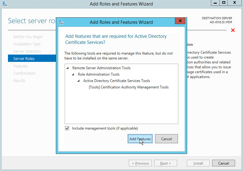
Click Add Features.
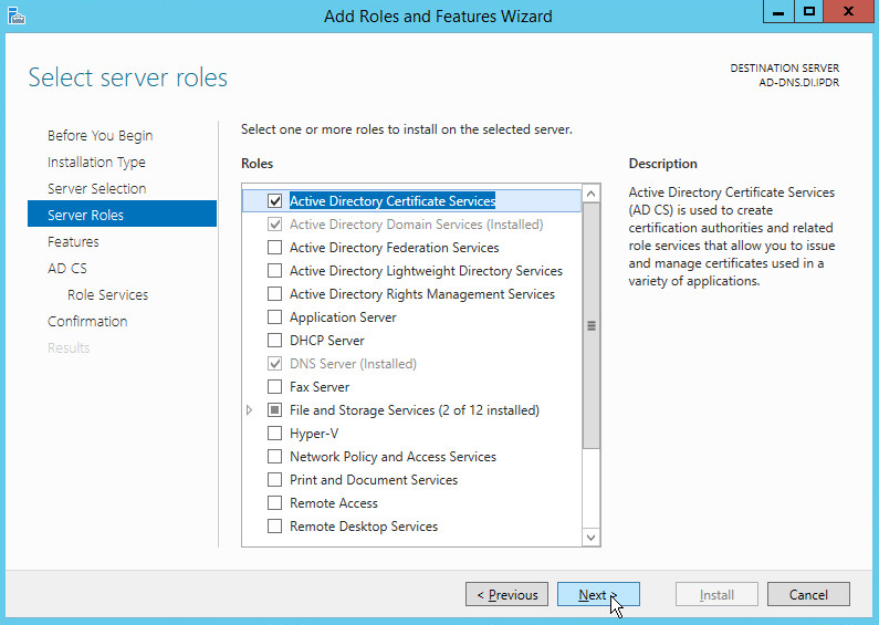
Click Next.
Click Next.
Click Next.
Check the box next to Certification Authority.
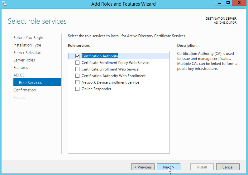
Click Next.
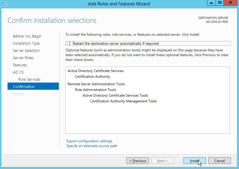
Click Install.
Wait for the installation to complete.
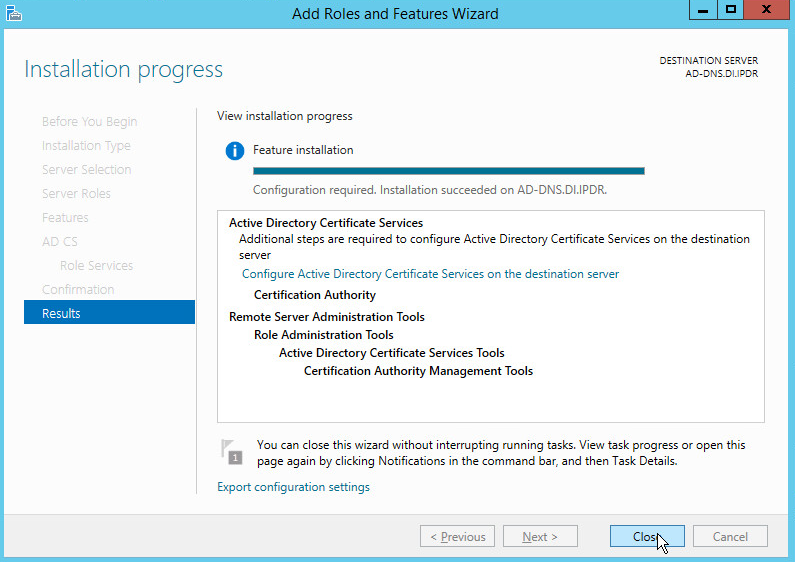
Click Close.
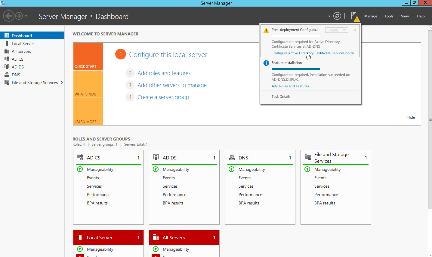
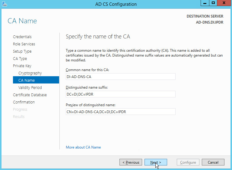
Click Configure Active Directory Certificate Services on the destination server.
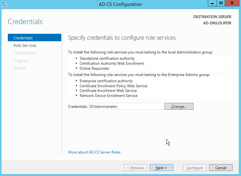
Click Next.
Check the box next to Certification Authority.
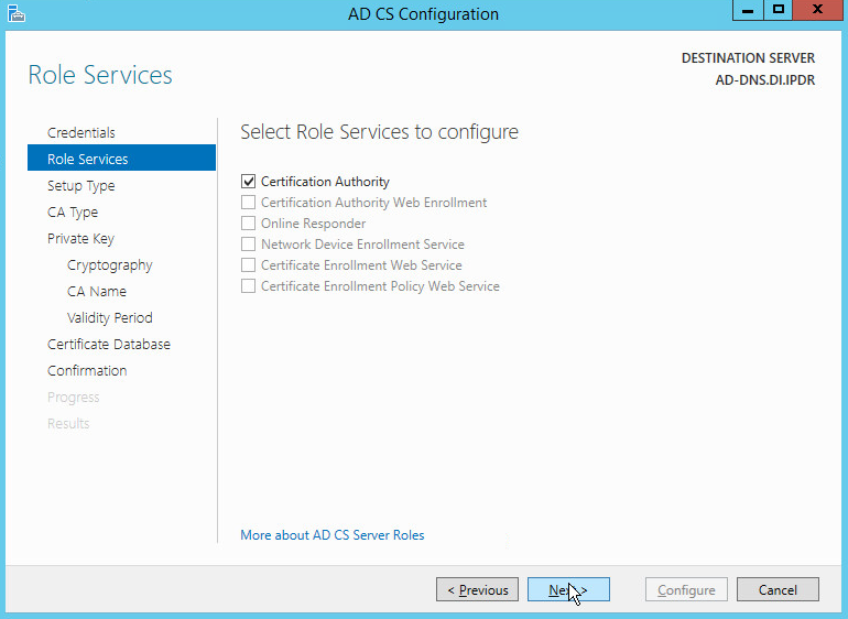
Click Next.
Select Enterprise CA.
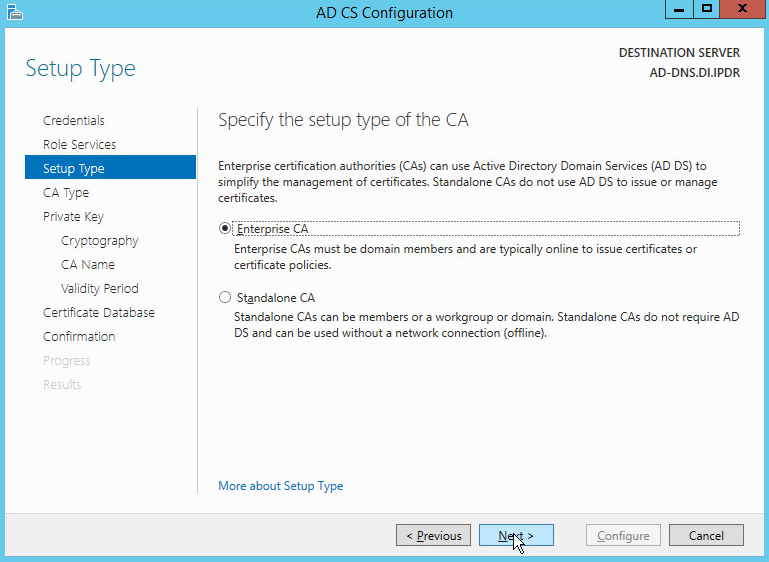
Click Next.
Select Root CA.
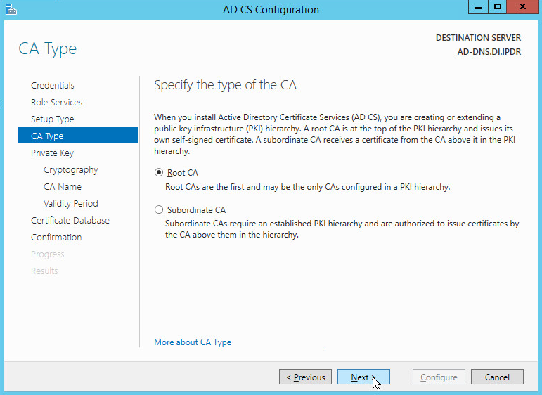
Click Next.
Select Create a new private key.
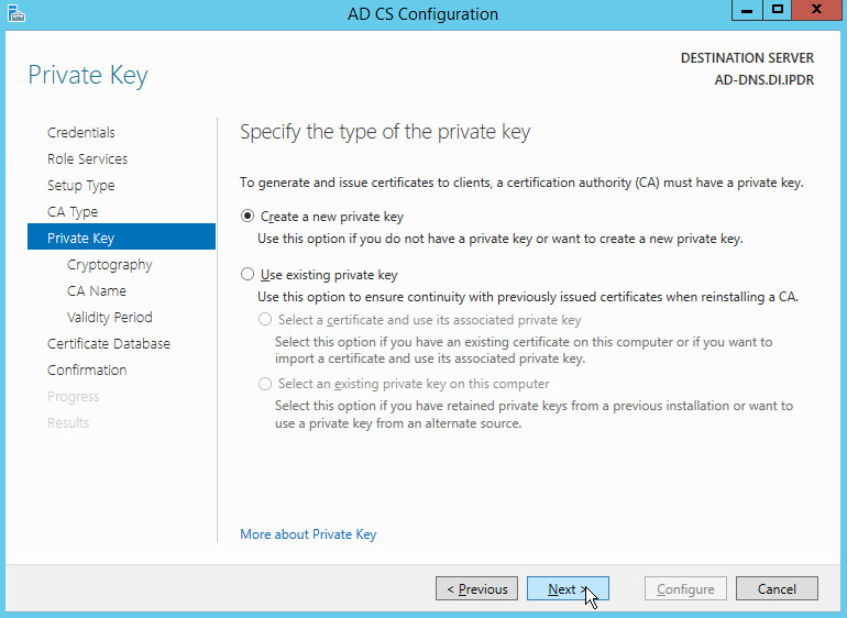
Click Next.
Select RSA#Microsoft Software Key Storage Provider.
Set the Key length to 2048.
Select SHA512 from the list.
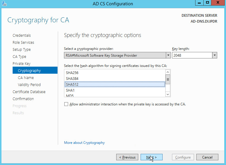
Click Next.
Click Next.
Set the time to 5 years.
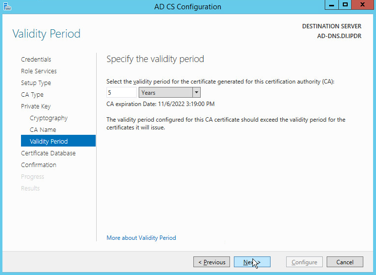
Click Next.
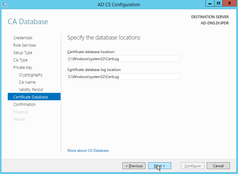
Click Next.
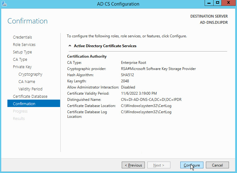
Click Configure.
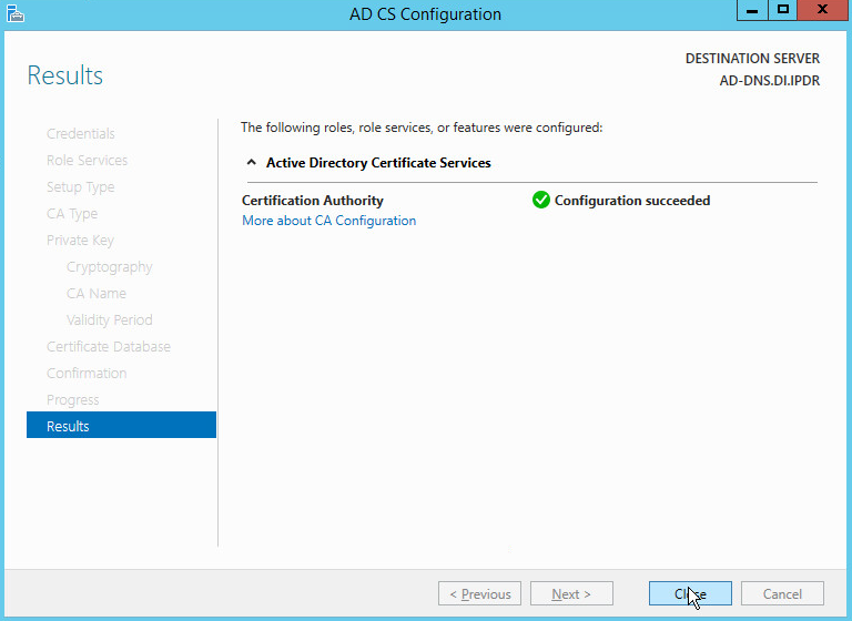
Click Close.
2.1.3 Configure Account to Add Computers to Domain
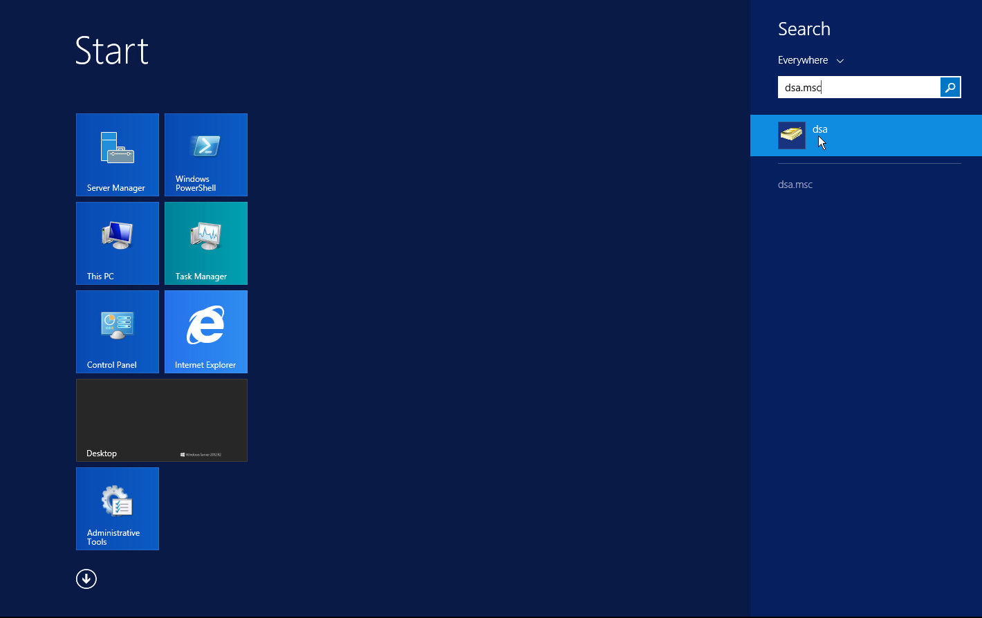
Open the Start menu.
Enter dsa.msc and run the program.
Right-click on Users in the left panel.
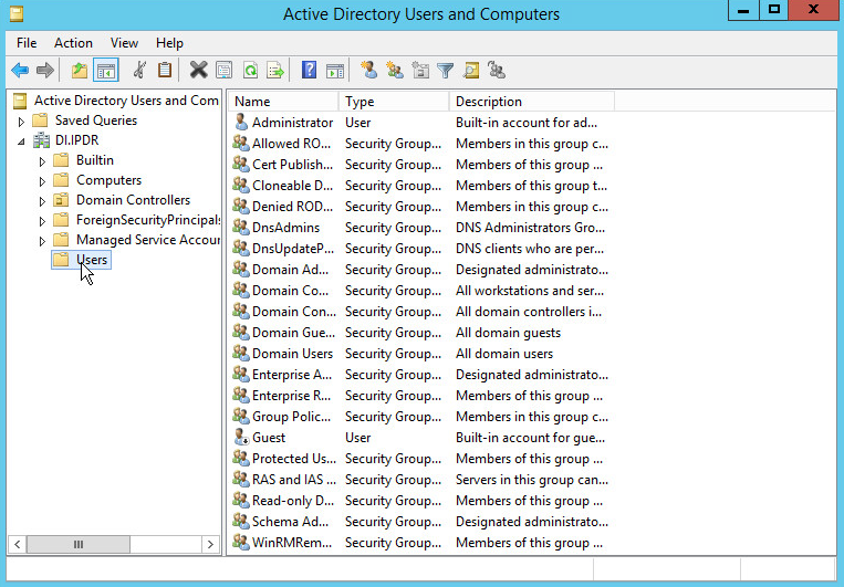
Click Delegate Control.
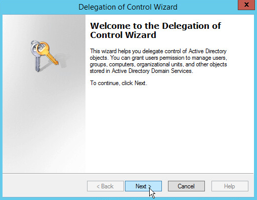
Click Next.
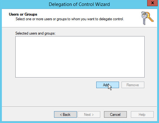
Click Add to select users or groups.
Add users or groups.
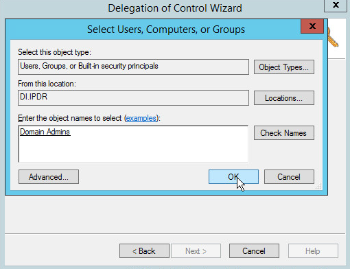
Click OK.
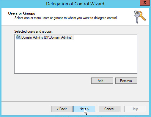
Click Next.
Choose Create a custom task to delegate.
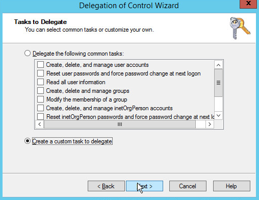
Click Next.
Choose Only the following objects in the folder.
Check the box next to Computer objects.
Check the box next to Create selected objects in this folder.
Check the box next to Delete selected objects in this folder.
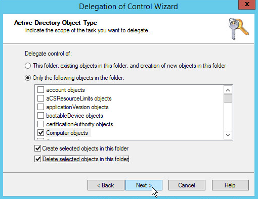
Click Next.
Check the boxes next to Reset password, Read and write account restrictions, Validated write to DNS host name, and Validated write to service principal name.
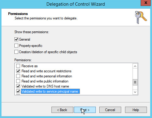
Click Next.
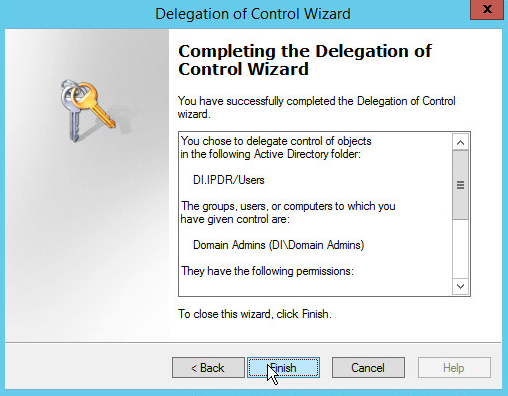
Click Finish.
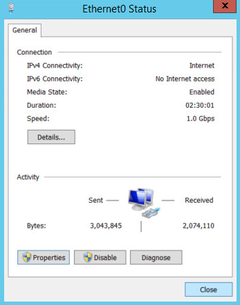
2.1.4 Adding Machines to the Domain
Right-click the network icon in the task bar on a computer that you wish to add to the domain.
Click Open Network and Sharing Center.
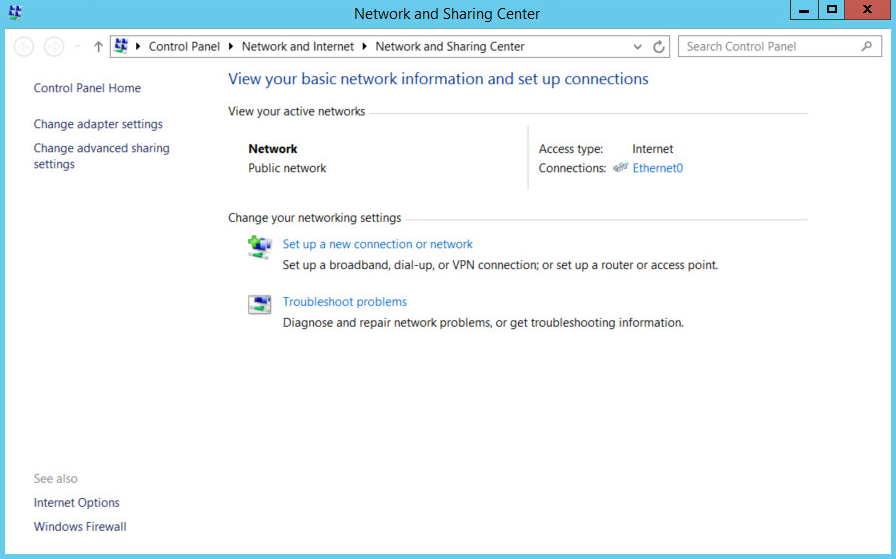
Click the name of the internet adapter.
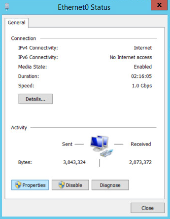
Click Properties.
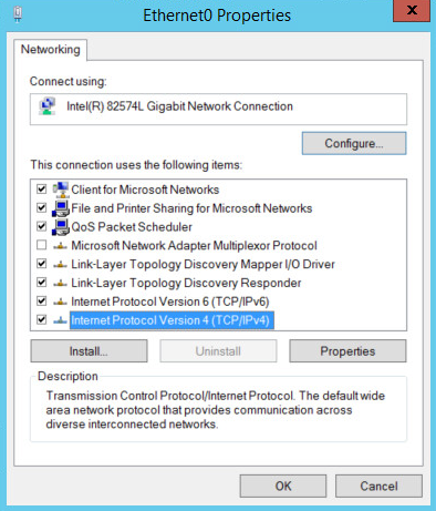
Double-click Internet Protocol Version 4 (TCP/IPv4).
Select Use the following DNS server addresses.
Enter the IP address of the DNS server.
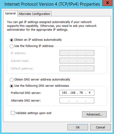
Click OK.
Click OK.
Click Close.
Navigate to This PC.
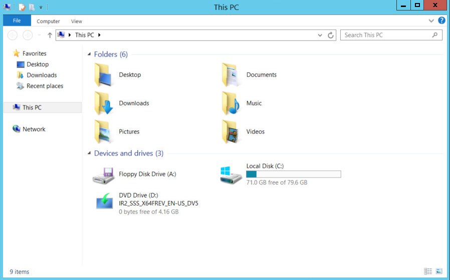
Right-click in the window and click Properties.
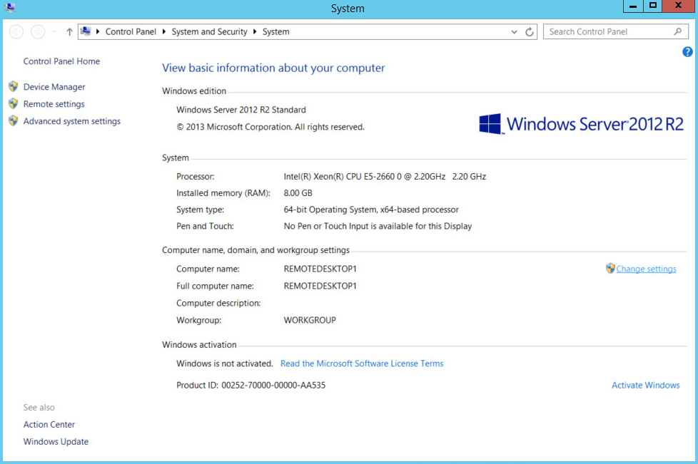
Click Change Settings.
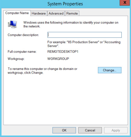
Click Change.
Select Domain.
Enter the domain.
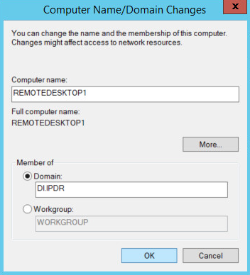
Click OK.
Enter the username and password of an account with privileges to add computers to the domain.
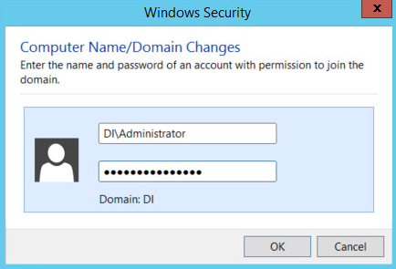
Click OK.
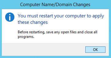
Click OK when prompted to restart the computer.
2.1.5 Configure Active Directory to Audit Account Activity
Open the Start menu.
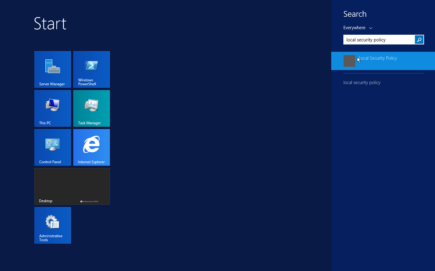
Enter “Local Security Policy” in the search bar and open the program.
Navigate to Local Policies > Audit Policy.
Right-click Audit account management.
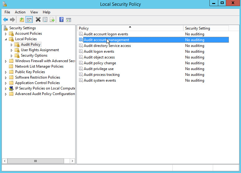
Click Properties.
Check the boxes next to Success and Failure.
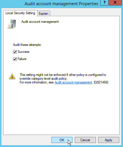
Click OK.
2.1.6 Configure Reverse Lookup Zones
Open DNS Manager by right-clicking the DNS server in Server Manager.
Click Reverse Lookup Zones.

Click Action > New Zone.
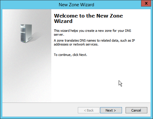
Click Next.
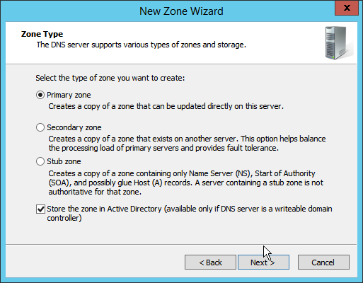
Click Next.
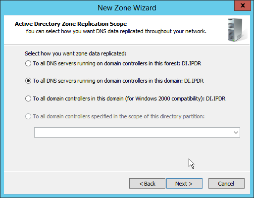
Click Next.
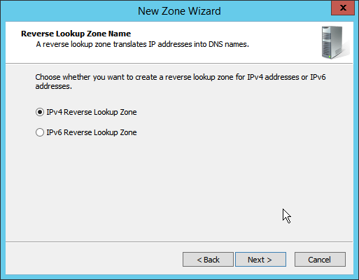
Click Next.
Enter the first three parts of the IP address of the Active Directory (AD)/DNS server (for example, 192.168.1).
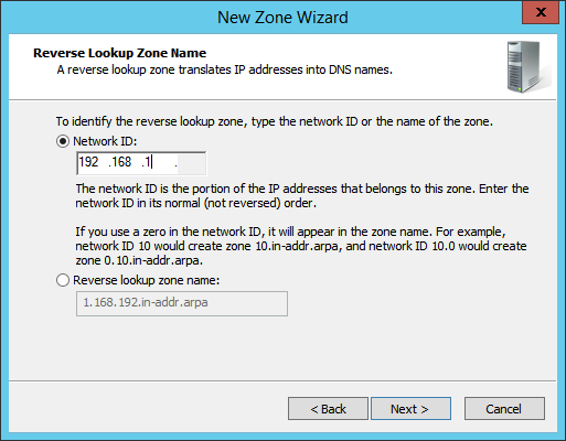
Click Next.
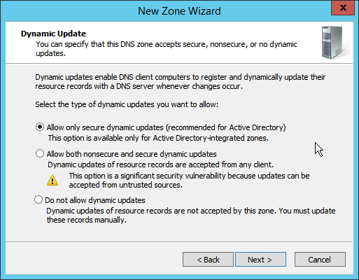
Click Next.
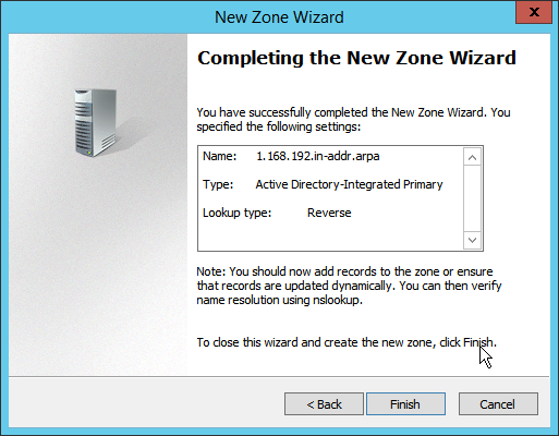
Click Finish.
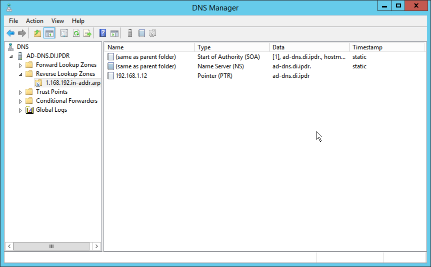
Click on the newly created reverse lookup zone.
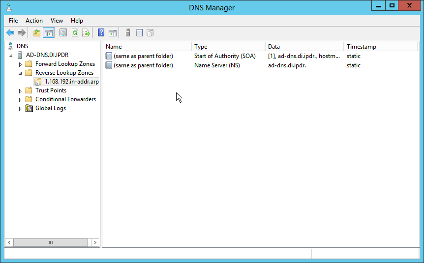
Right-click in the window and select New Pointer (PTR)….
Enter the IP address of the AD/DNS server.
Enter the hostname of the AD/DNS server.
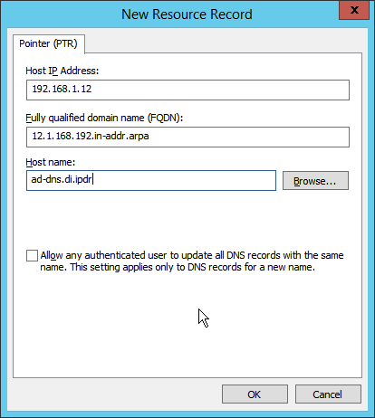
Click OK.
2.2 Microsoft Exchange Server
As part of our enterprise emulation, we include a Microsoft Exchange server. This section covers the installation and configuration process used to set up Microsoft Exchange on a Windows Server 2012 R2 machine.
2.2.1 Install Microsoft Exchange
Run Exchange2016-x64.exe.
Choose the directory for the extracted files.
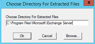
Click OK.
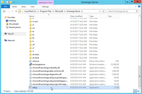
Enter the directory and run setup.exe.
Select Connect to the Internet and check for updates.
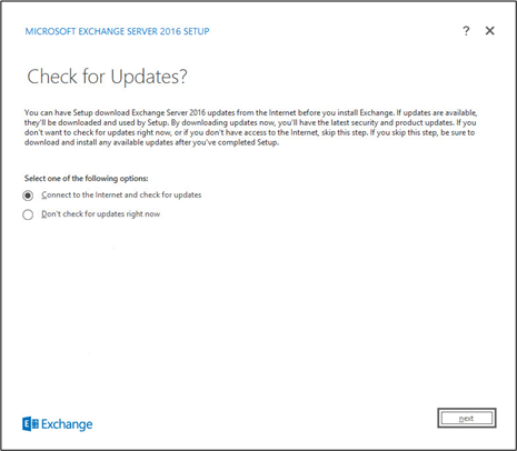
Click Next.
Wait for the check to finish.
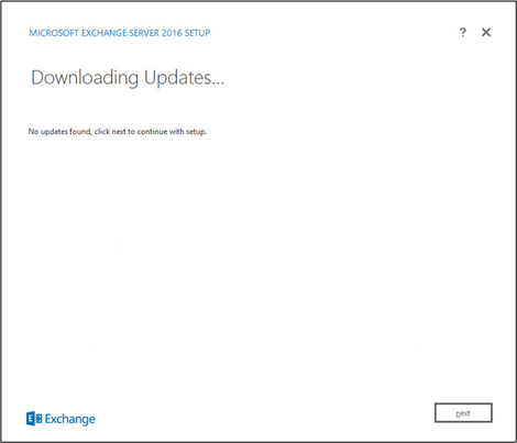
Click Next.
Wait for the copying to finish.
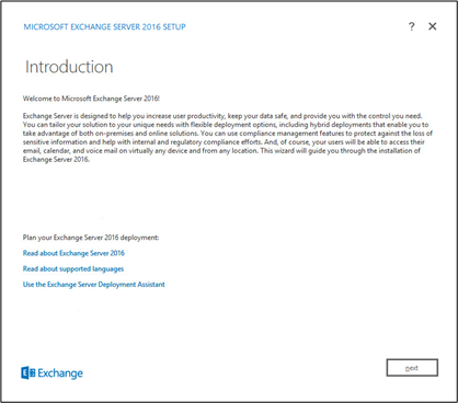
Click Next.
Click I accept the terms in the license agreement.
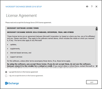
Click Next.
Click Use Recommended Settings.
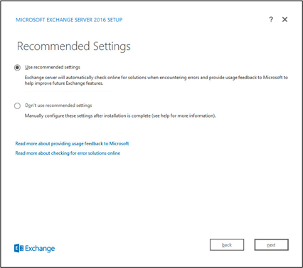
Click Next.
Check Mailbox role.
Check Automatically install Windows Server roles and features that are required to install Exchange Server.
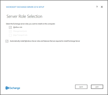
Click Next.
Specify the installation path for MS Exchange.
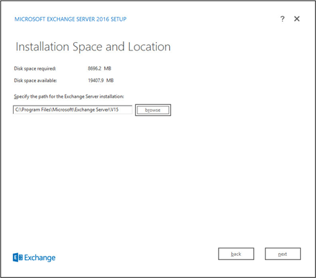
Click Next.
Specify the name for the Exchange organization, e.g., DI.
Decide whether to apply split permissions based on the needs of the enterprise.
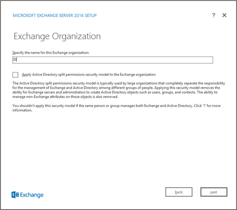
Click Next.
Select No.
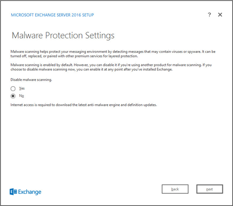
Click Next.
Install any prerequisites listed.
If necessary, restart the server and rerun setup.exe, following through steps 3–22 again.
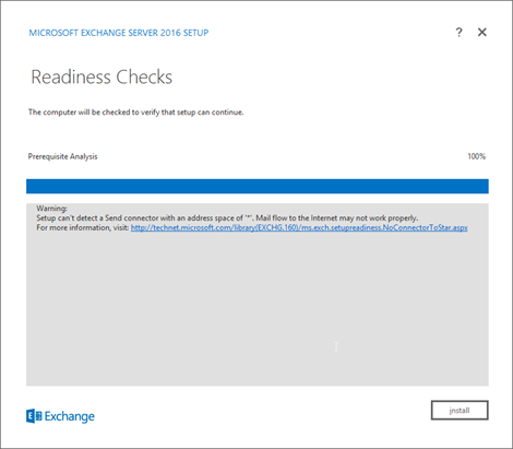
Click Install.
2.3 Windows Server Hyper-V Role
As part of our simulated enterprise, we include a Windows Hyper-V server. This section covers the instructions for installing the Windows Server Hyper-V Role on a Windows Server 2012 R2 machine.
The instructions for enabling the Windows Server Hyper-V Role are retrieved from https://technet.microsoft.com/en-us/library/hh846766(v=ws.11).aspx and are replicated below for preservation and ease of use.
2.3.1 Production Installation
In Server Manager on the Manage menu, click Add Roles and Features.
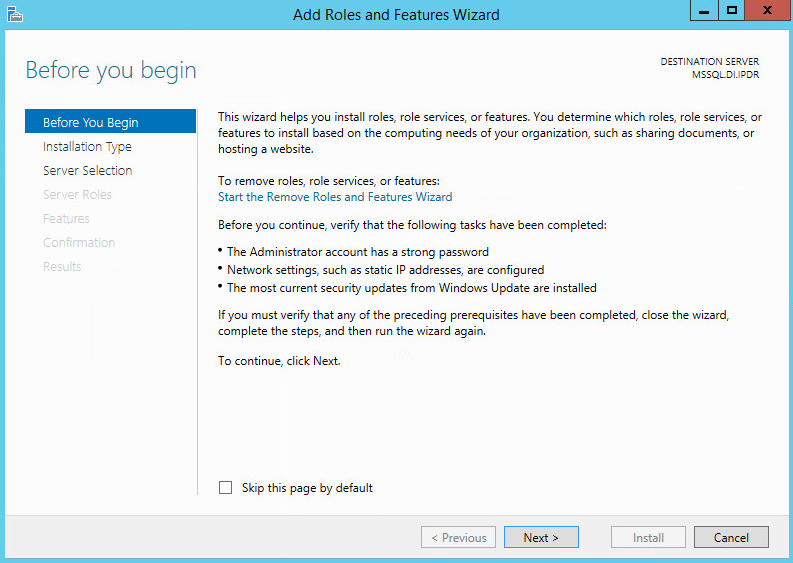
On the Before you begin page, verify that your destination server and network environment are prepared for the role and feature you want to install.
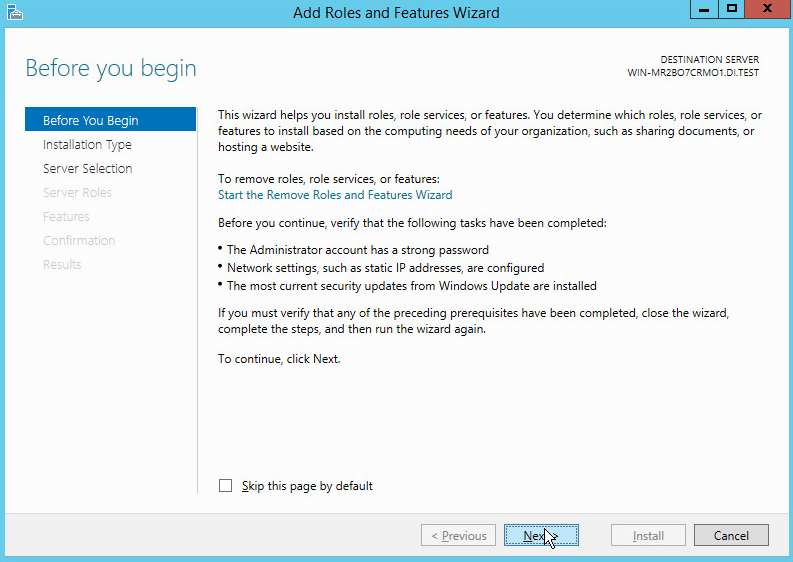
Click Next.
On the Select installation type page, select Role-based or feature-based installation.
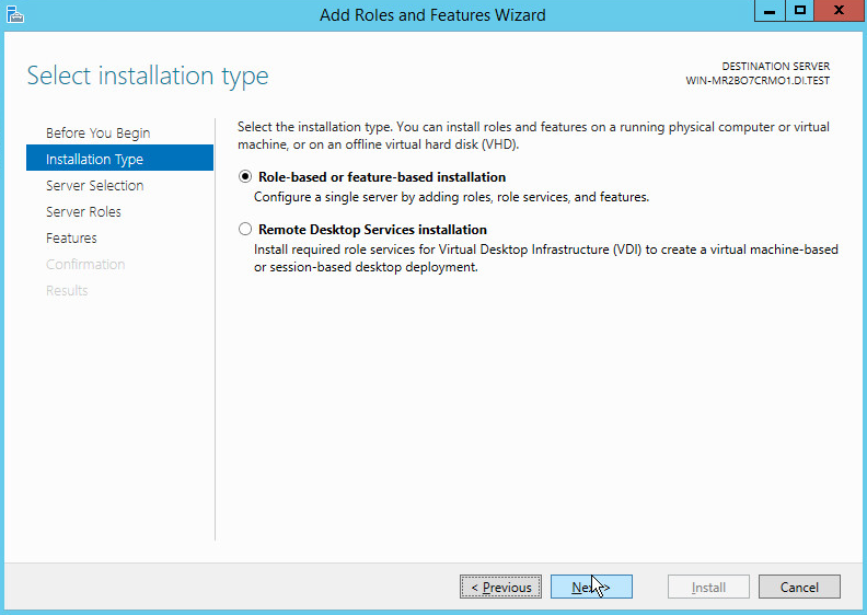
Click Next.
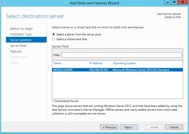
On the Select destination server page, select a server from the server pool.
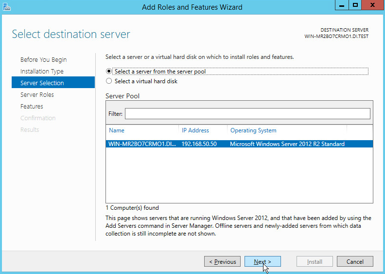
Click Next.
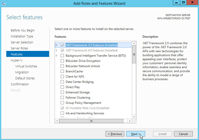
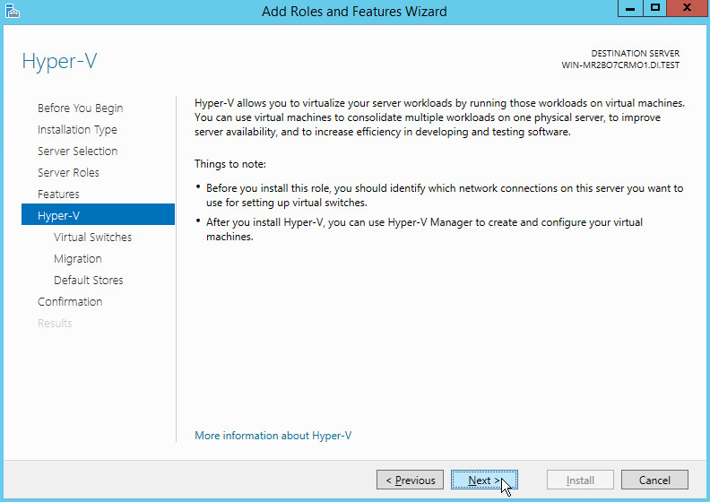
On the Select server roles page, select Hyper-V.
To add the tools that you use to create and manage virtual machines, click Add Features.
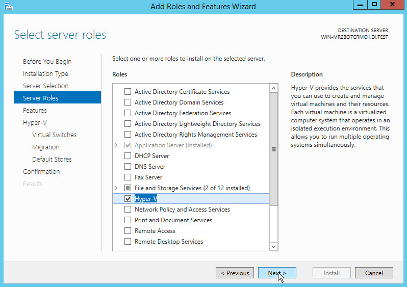
Click Next.
Click Next.
Click Next.
On the Create Virtual Switches page, select the appropriate options.
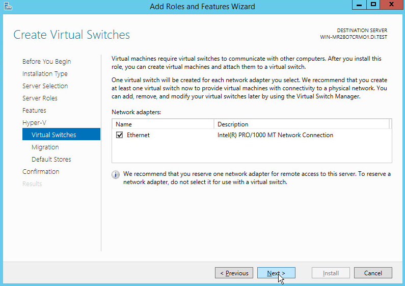
Click Next.
On the Virtual Machine Migration page, select the appropriate options.
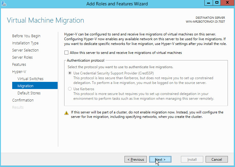
Click Next.
On the Default Stores page, select the appropriate options.
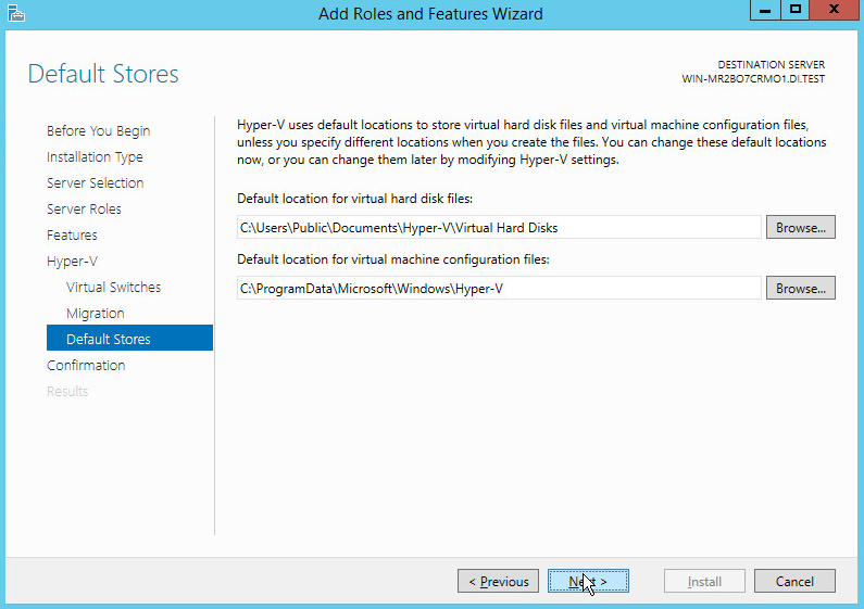
Click Next.
On the Confirm installation selections page, select Restart the destination server automatically if required.
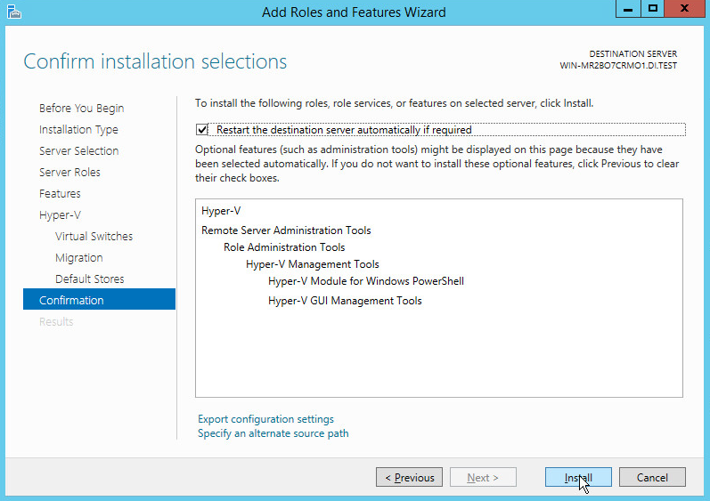
Click Install.
When installation is finished, verify that Hyper-V installed correctly. Open the All Servers page in Server Manager, and select a server on which you installed Hyper-V. Check the Roles and Features tile on the page for the selected server.
2.4 MS SQL Server
As part of both our enterprise emulation and data integrity solution, we include a Microsoft Structured Query Language (MS SQL) Server. This section covers the installation and configuration process used to set up Microsoft SQL Server on a Windows Server 2012 R2 machine.
2.4.1 Install and Configure MS SQL
Acquire SQL Server 2014 installation media.
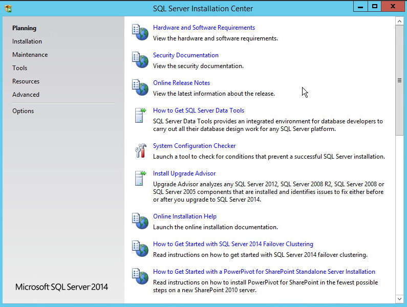
Locate the installation media in the machine and click on SQL2014_x64_ENU to launch SQL Server Installation Center.
On the left menu, select Installation.
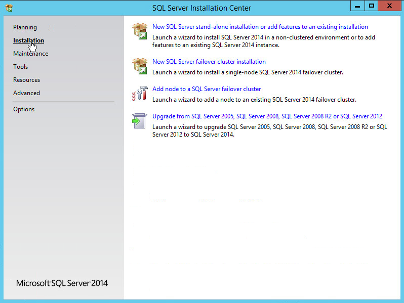
Select New SQL Server stand-alone installation or add features to an existing installation. This will launch the SQL Server 2014 setup.
In the Product Key section, enter your product key.
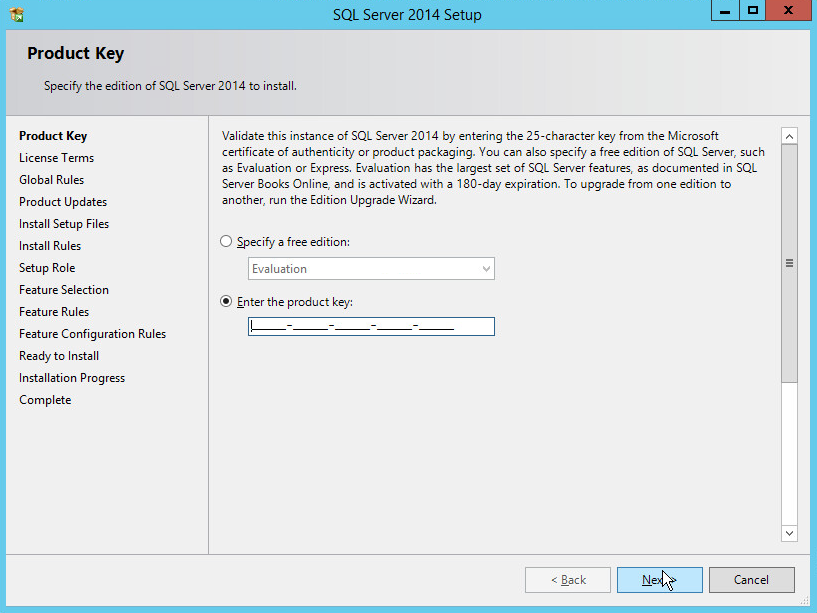
Click Next.
In the License Terms section, read and click I accept the license terms.
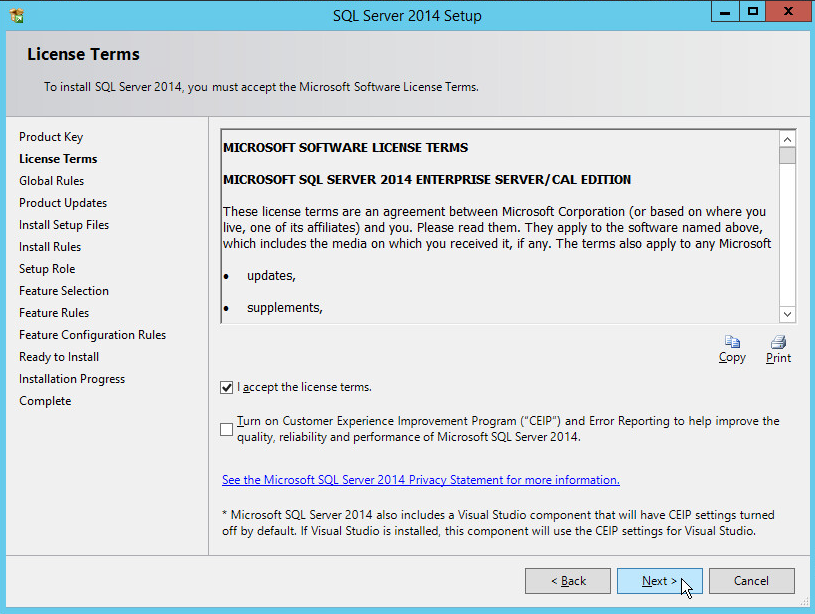
Click Next.
In the Install Rules section, note and resolve any further conflicts.
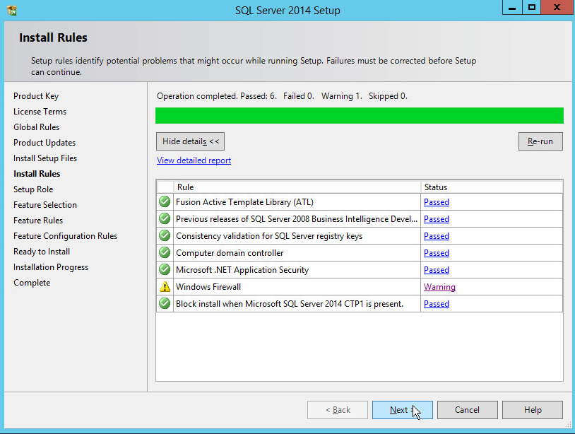
Click Next.
In the Setup Role section, select SQL Server Feature Installation.
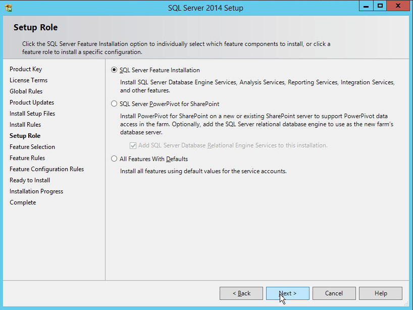
Click Next.
In the Feature Selection section, select the following options:
Database Engine Services
Client Tools Connectivity
Client Tools Backwards Compatibility
Client Tools SDK
Management Tools – Basic
Management Tools – Complete
SQL Client Connectivity SDK
Any other desired features
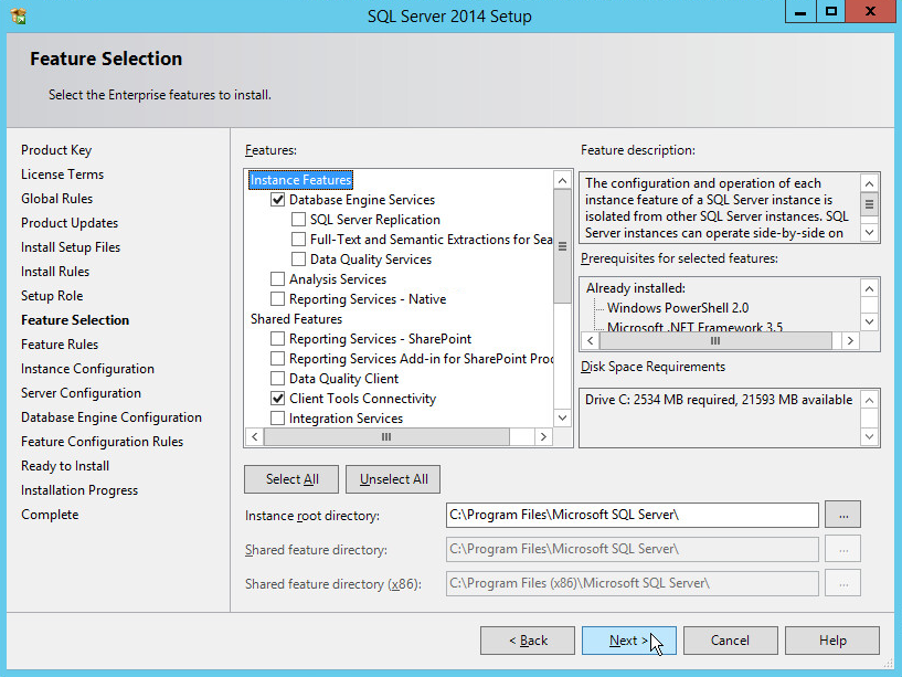
Click Next.
In the Instance Configuration section, select Default instance.
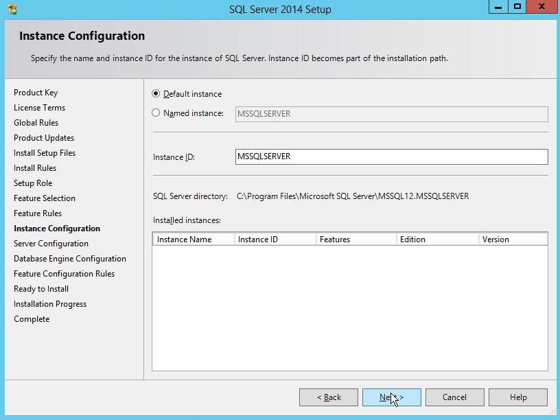
Click Next.
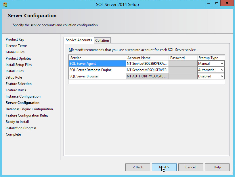
In the Server Configuration section, click Next.
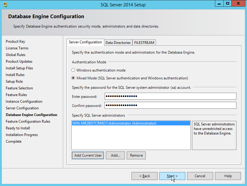
In the Database Engine Configuration section, make sure Mixed Mode is selected.
Add all desired users as Administrators under Specify SQL Server Administrators by pressing Add Current User.
For Domain accounts, simply type in $DOMAINNAME\$USERNAME into Enter the object names to select text box.
Click OK.
For local computer accounts, click on locations and select the computer’s name.
Click OK.
Type the username into the Enter the object names to select text box.
Once you are finished adding users, click Next.
In the Ready to install section, verify the installation and click Install.
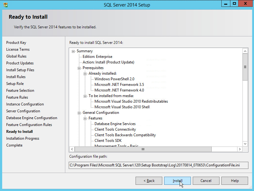
Wait for the installation to finish.
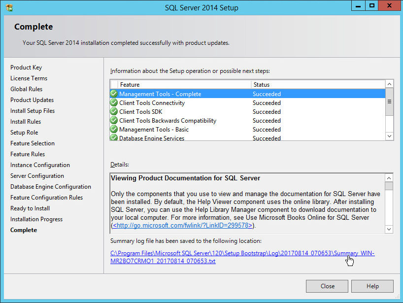
Click Close.
2.4.2 Open Port on Firewall
Open Windows Firewall with Advanced Security.
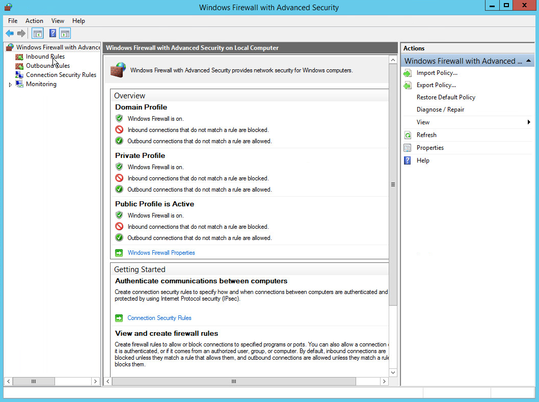
Click Inbound Rules.
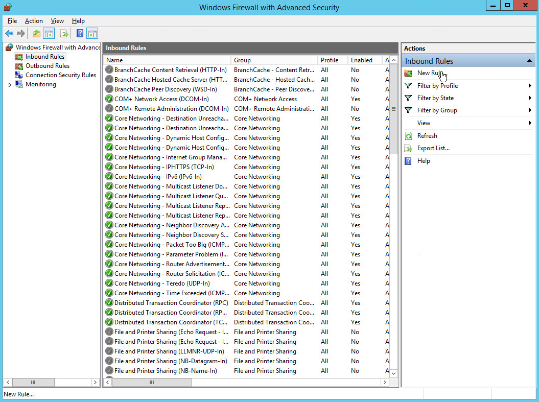
Click New Rule.
Select Port.
Click Next.
Select TCP and Specific local ports.
Type 1433 into the text field.
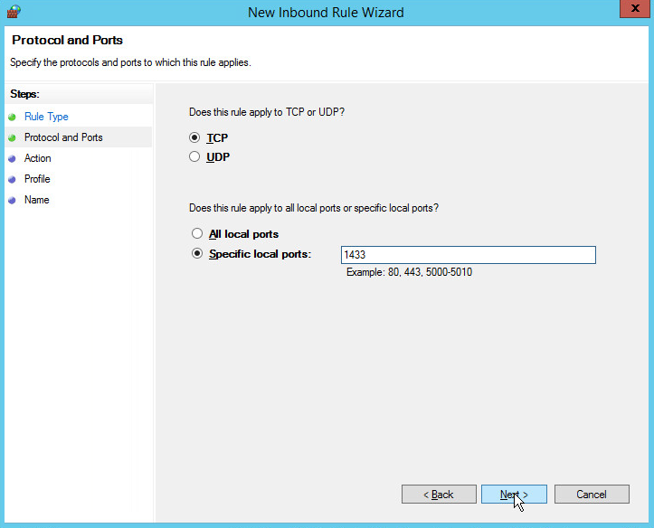
Click Next.
Select Allow the connection.
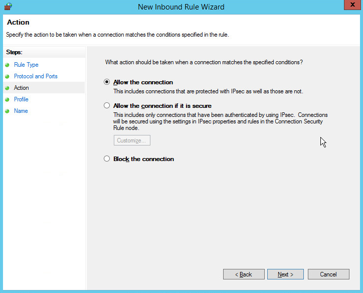
Click Next.
Select all applicable locations.
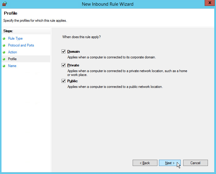
Click Next.
Name the rule Allow SQL Access.
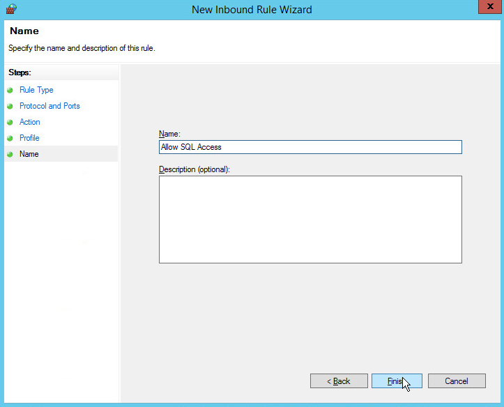
Click Finish.
2.4.3 Add a New Login to the Database
Open SQL Server Management Studio.
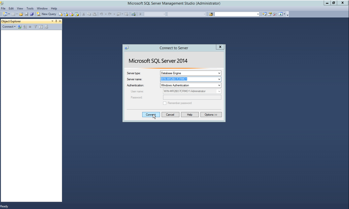
Click Connect to connect to the database.
In the Object Explorer window, expand the Security folder.
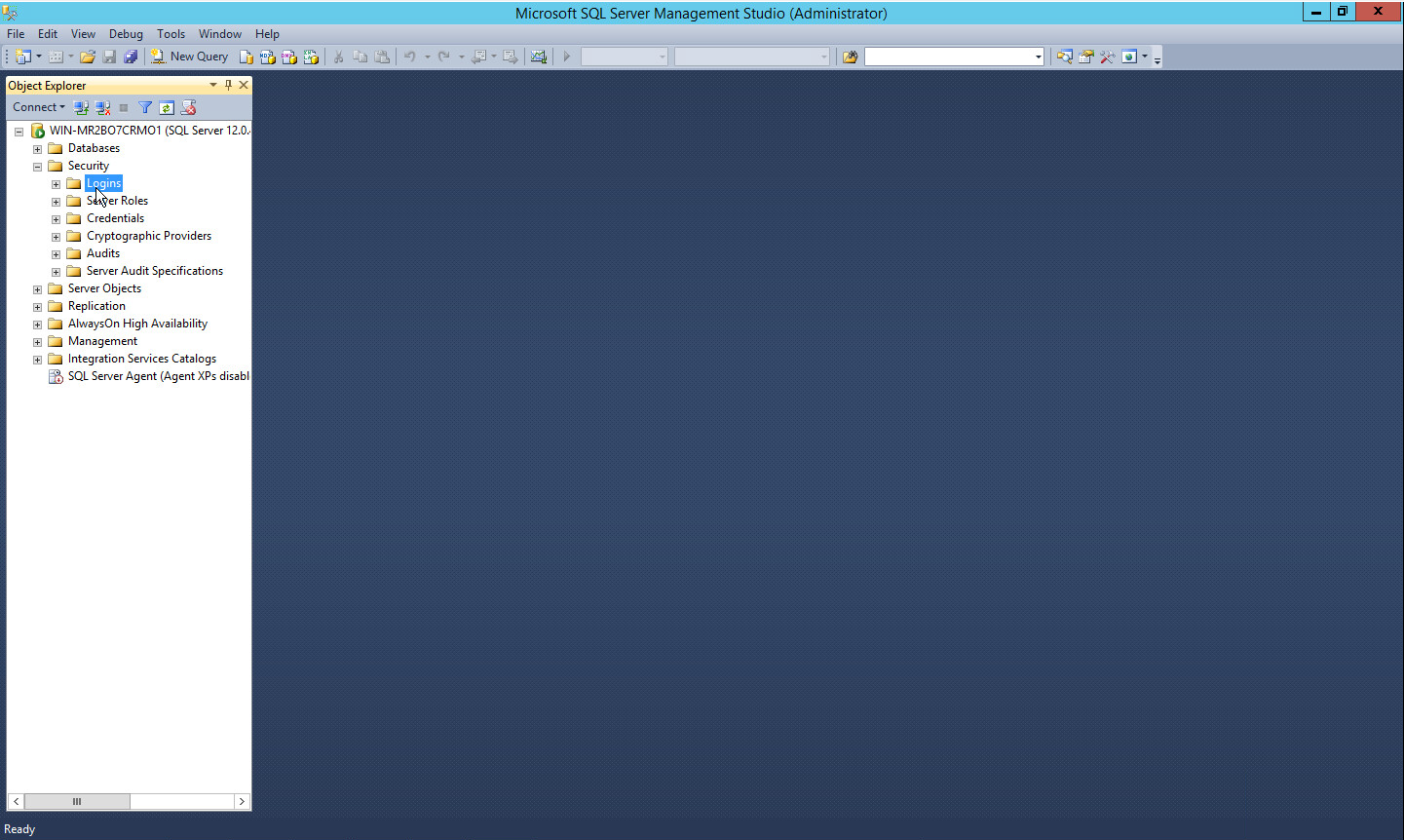
Right-click on the Logins folder and click New Login….
Input the desired user.
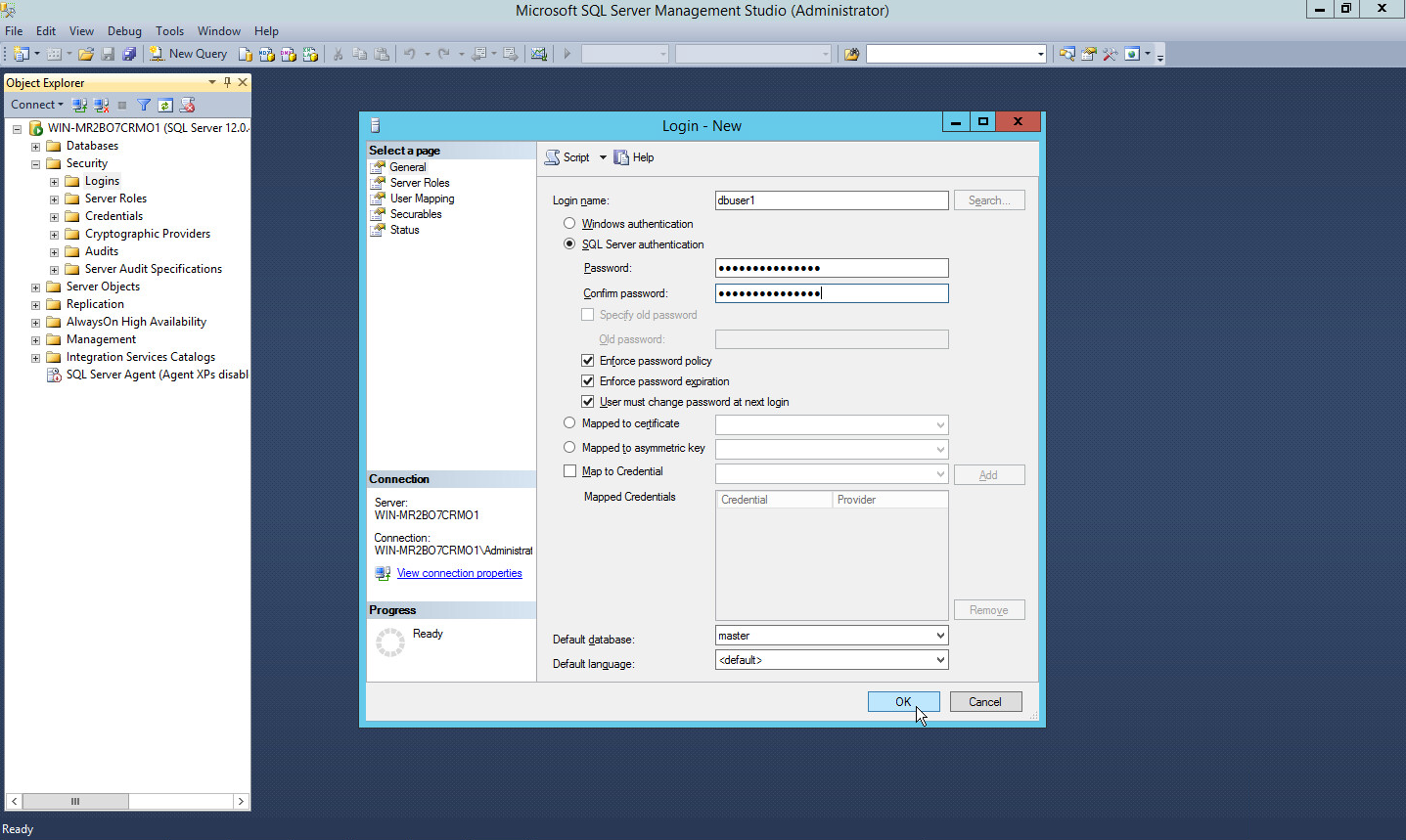
Click OK.
2.5 Microsoft IIS Server
As part of our enterprise emulation, we include a Microsoft Internet Information Services (IIS) server. This section covers the installation and configuration process used to set up Microsoft Exchange on a Windows Server 2012 R2 machine. This was conducted on the same machine as in Section 2.4.
2.5.1 Install IIS
Open Server Manager.
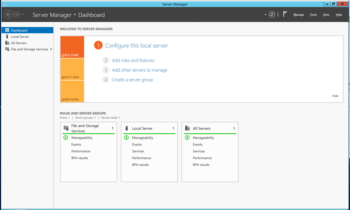
Click Add Roles and Features.
Click Next.
Select Role-based or feature-based installation.

Click Next.
Select MSSQL (or the correct Windows Server name) from the list.
Click Next.
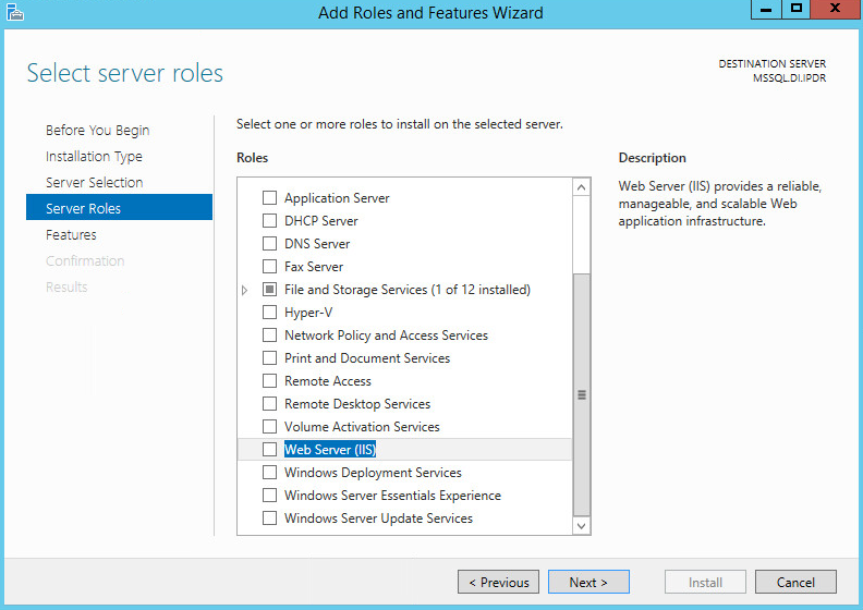
Check the box next to Web Server (IIS).

Click Add Features.
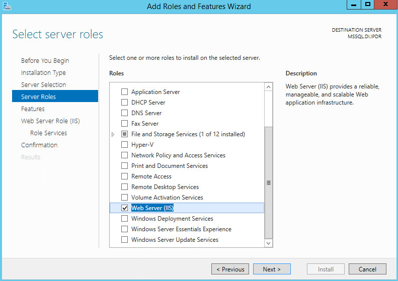
Click Next.
Ensure that all desired features are selected.

Click Next.

Click Next.
Ensure that Default Document, Directory Browsing, HTTP Errors, Static Content, HTTP Logging, and any other desired Role services are selected.

Click Next.
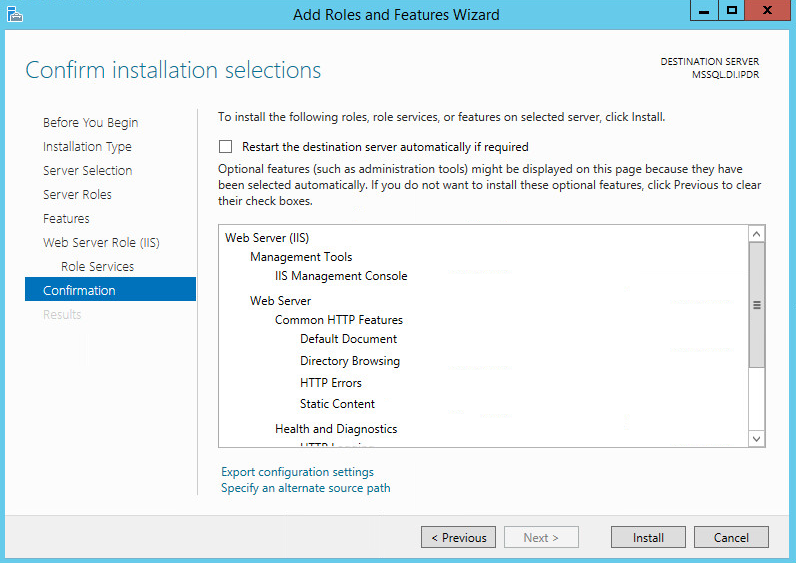
Click Install.
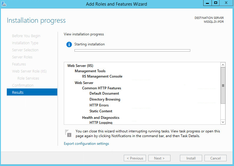
Wait for the installation to complete.
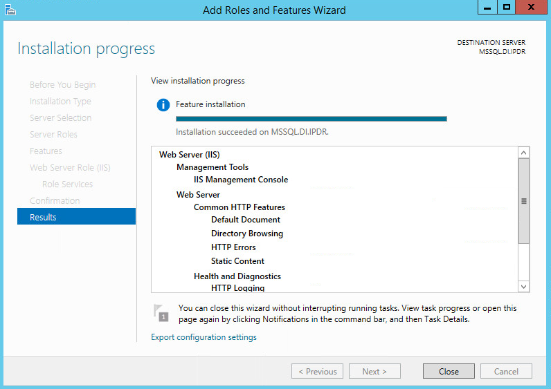
Click Close.
2.5.2 IIS Configuration
Open Windows Explorer and click This PC.
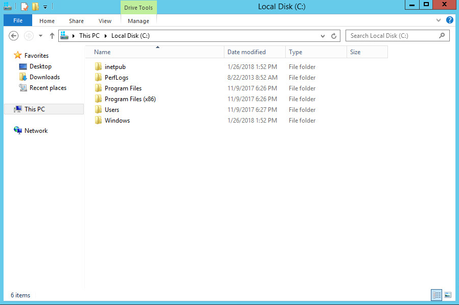
Right-click and select Create Folder.
Name the folder www.

Open the Internet Information Services (IIS) Manager.
Click the arrow next to MSSQL (or the chosen name of the server).
Click Sites.
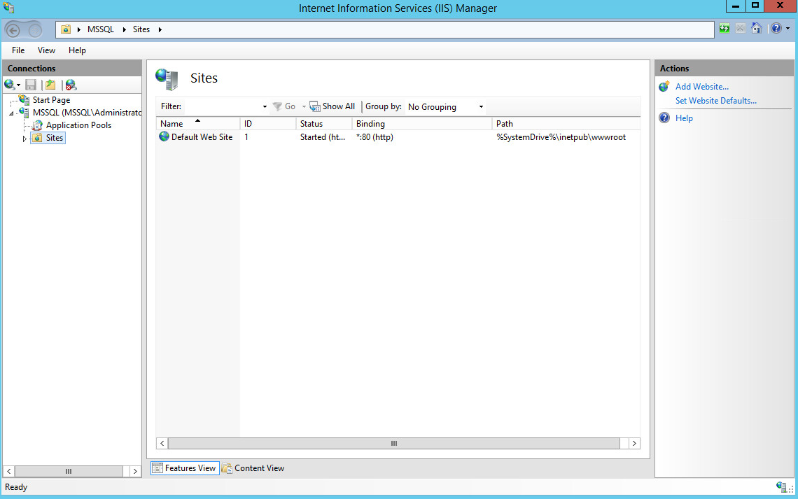
Click Add Website….
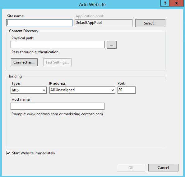
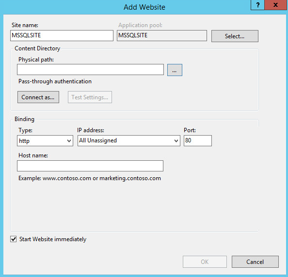
Enter the desired site name.
Click … under Physical path:.

Locate and select the folder created in step 3.
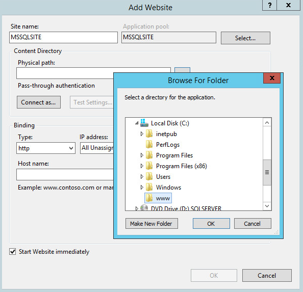
Click OK.
Set Type to http and Port to 80.
Ensure that the IP address and Host name fields are filled in with the correct information for the machine.
Ensure that Start Website immediately is selected.
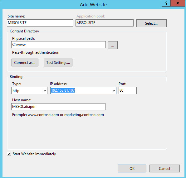
Click OK.
2.6 GreenTec WORMdisks
See the Installation of GreenTec Command Line Utilities document, which should accompany the installation disk, for a detailed guide on how to install the GreenTec command line utilities. Furthermore, refer to the GT_WinStatus User Guide, which should also accompany the installation disk, for instructions on how to effectively use GreenTec WORMdisks to preserve data. Read these instructions carefully, as locking GreenTec WORMdisks can result in making some or all of the disk or the entire disk unusable. Having portions of the disk or the entire disk permanently locked is sometimes desirable, but it is dependent on the needs of your organization, e.g., if you want to store backup information or logs securely.
The GT_WinStatus User Guide provides instructions for locking and temporarily locking disk sectors. In this practice guide, we will not include instructions on when to lock GreenTec WORMdisks. However, we will provide instructions detailing how to save data to these disks and various commands used in manipulating the disks. Below, find descriptions of some commands useful for automation of GreenTec WORMdisks. Actual automation of these disks will vary per organization.
2.6.1 Format GreenTec WORMdisks
To format GreenTec WORMdisks for use, the following command can be used.
> gt_format.exe <disk number> /parts:<number of parts> /label:<id>
This command can be used to split a disk into a specified number of partitions, with each partition being labeled according to the label id specified.
For example, this command will split drive 1 into four parts, labeled DI001, DI002, DI003, and DI004:
> gt_format.exe 1 /parts:4 /label:DI
Formatting drive 1 partition 1 file system NTFS label "DI001"

Format successful

Formatting drive 1 partition 2 file system NTFS label "DI002"

Format successful

Formatting drive 1 partition 3 file system NTFS label "DI003"

Format successful

Formatting drive 1 partition 4 file system NTFS label "DI004"

Format successful
2.6.2 Obtain Status Information About GreenTec WORMdisks
To verify information about GreenTec WORMdisks, use the following command.
> wvlist.exe <drive number>
This command can be used to display basic information about a drive, such as the amount of space of each partition, whether it is a WORMdisk, whether they have been locked, and what drive letter to which they are mapped.
For example, this command will list the characteristics of drive 1.
> wvlist.exe 1
WVLIST: List WORM Volume (WDV) Status on Physical WORMdisks(tm).

Copyright (C) 2015 GreenTec-USA, Inc. All rights reserved.

    Drive#=1 Type=ATA F/W=GT5G Size=500{GB)

        > IS WORM > IS *NOT* Finalized

        **** WORMdisk Volume (WDV) Info ****

        WDV # TB ENFORCED GREENTEC TLOCKED

        <---> <---> <------> <------> <----->

         001 0.125 NO YES NO G:\

         002 0.125 NO YES NO H:\

         003 0.125 NO YES NO I:\

         004 0.125 NO YES NO J:\
2.6.3 Map GreenTec WORMdisks to Drive Letters
To unmap a partition from a drive letter, use the following command:
> wvmap.exe <drive letter>:For example,
> wvmap.exe H:will unmap H:, making it available for mapping to another partition.
To map a partition to a drive letter, use the following command:
> wvmap.exe <drive letter>: <drive number>.<partition number>For example,
> wvmap.exe H: 1.2will map the second partition of drive 1 to H:, making files available through accessing that drive letter.
To map the next partition to a drive letter, use the following command:
> wvnext.exe <drive letter>:For example, if H: is mapped to partition 2 of drive 1 (1.2)
> wvnext.exe H:will attempt to map H: to partition 3 of drive 1 (1.3).
2.6.4 Activate Write Protection in GreenTec WORMdisks
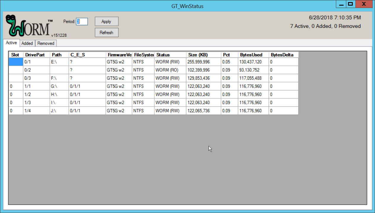
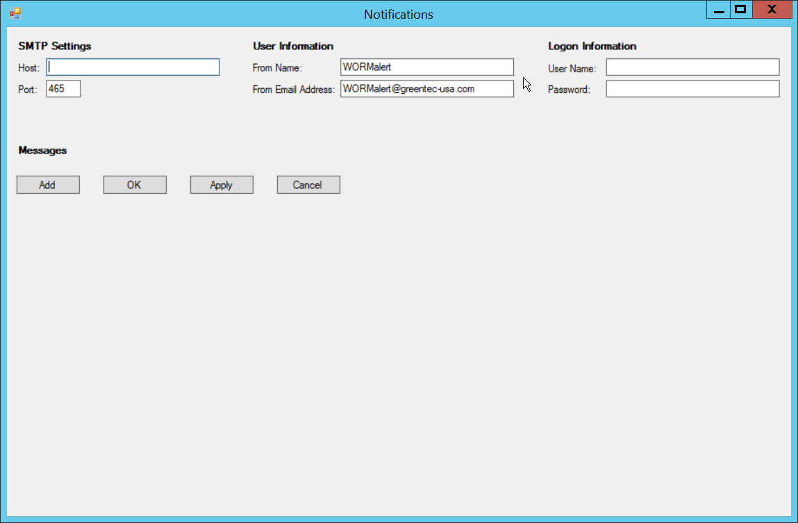
Running GT_WinStatus.exe will open the Graphical User Interface (GUI), which displays various information such as drive mappings, partitions, total space, and space used, as well as a range of other options.
More columns can be added by right-clicking anywhere in the Active window, opening the Settings window.
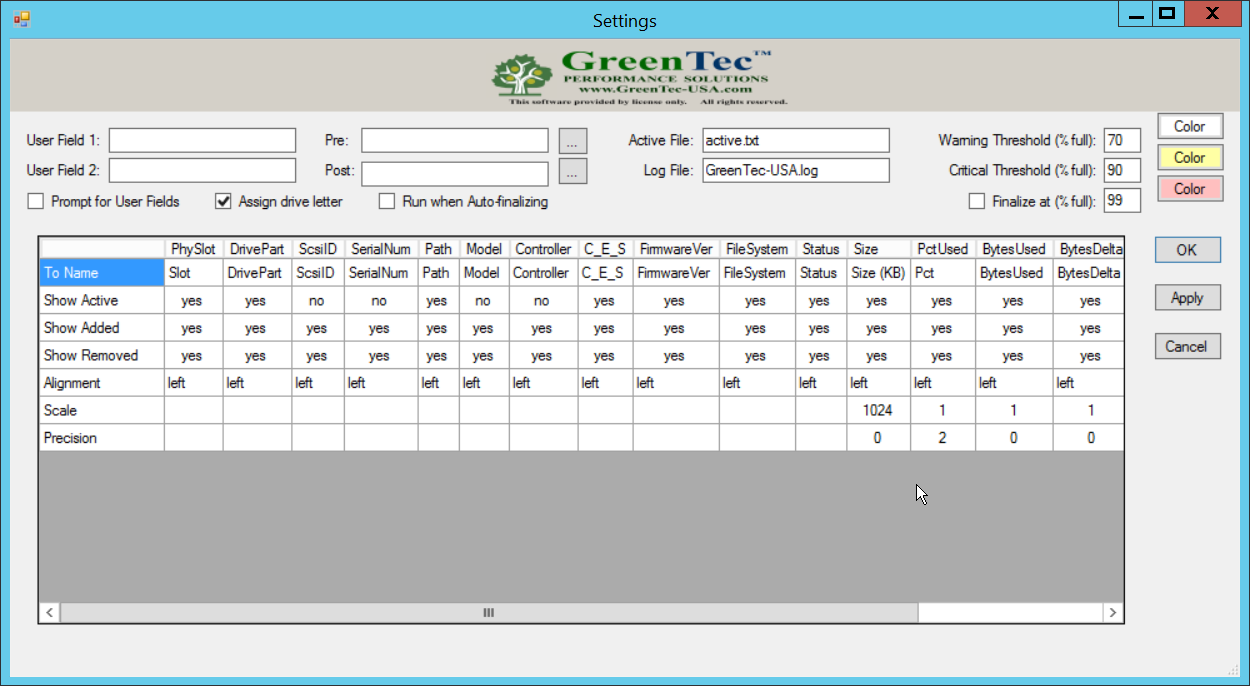
In the Settings window, User Field 1 and User Field 2 are for any metadata to be stored for a drive. Pre: runs a script prior to finalizing a drive, and Post: runs a script after finalizing a drive.
Also, from the Settings window, right-clicking on Critical Threshold or Warning Threshold will allow the user to set up alert preferences for drives that are nearly full (at a configurable percent value).
To display the GUI with options to lock and enforce locks on drives, the following command must be used to start the GUI:
> GT_WinStatus.exe /tlock /enfThis will add columns called TLock and Enforce (as well as the ability to use the Finalize column).
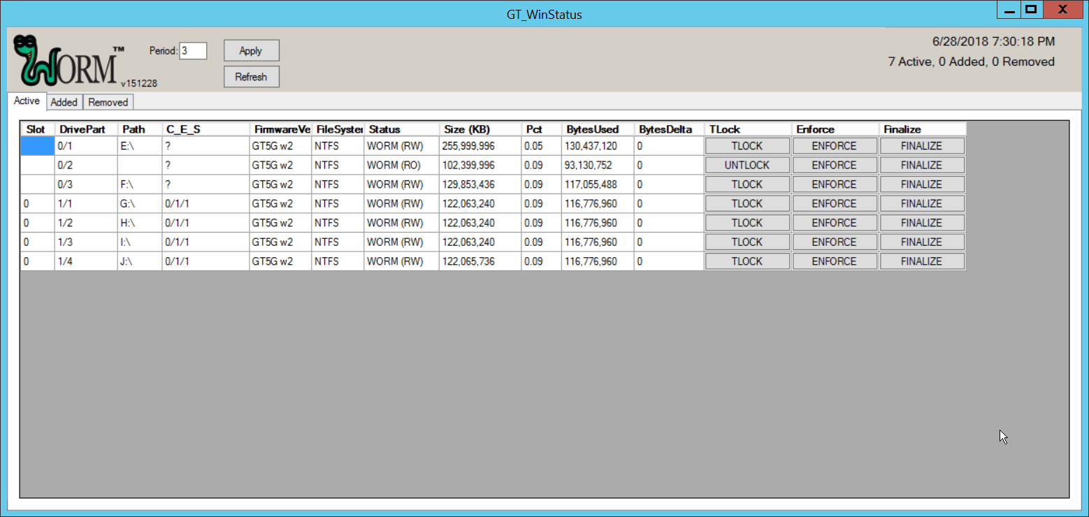
The TLock column temporarily locks/unlocks a partition of the drive. This is useful to prevent modification during times when modification should be disallowed.
The Enforce column is a permanent incremental lock. This means that it permanently prevents modification for the selected volume of a drive as well as all volumes that come before that volume on the drive. Once these sections are enforced, they cannot be written to ever again. This functionality is particularly useful in protecting data or backups that must never be modified, but as the enforce function is permanent, it must be used carefully.
The Finalize column permanently locks the entire drive. This is useful when a drive is full and no longer needs to be written to. Data can still be read and copied from this drive to other places, but no write actions will be possible after this is used, so it also must be used carefully.
2.7 CryptoniteNXT
See the CryptoniteNXT 2.6.2 Unified Installation Guide, which should accompany the device for a detailed guide on how to install CryptoniteNXT on the provided device.
The CryptoniteNXT 2.6.2 Unified Installation Guide provides a full installation on both the CryptoniteNXT device and the management workstation. When finished, it should be possible to log in on the management workstation and interact with the CryptoniteNXT ACC GUI. Instructions are provided below for performing various useful functions, including adding new devices/users, as well as creating policy, but specific recommendations for policy are not provided, as those will be specific to the organization. Some integrations with other security products used in this guide will be provided, as exceptions for those products in CryptoniteNXT are often necessary for their functionality.
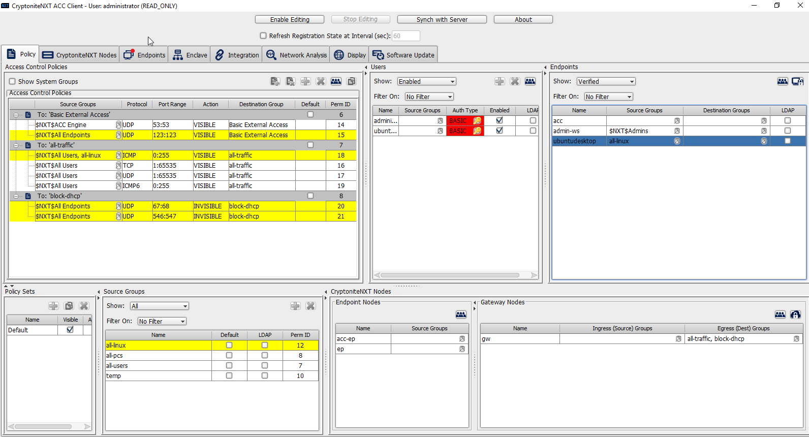
2.7.1 Configure Cryptonite NXT
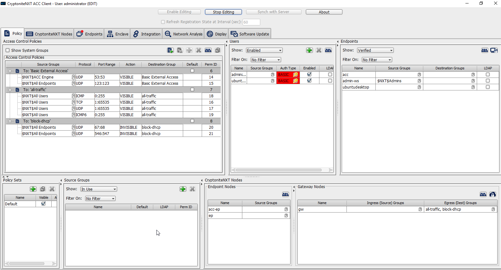
2.7.1.1 Verify a New Device
Open the CryptoniteNXT ACC GUI application.

Click OK.
Enter the password for the account created during the installation.
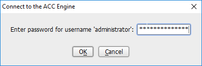
Click OK.
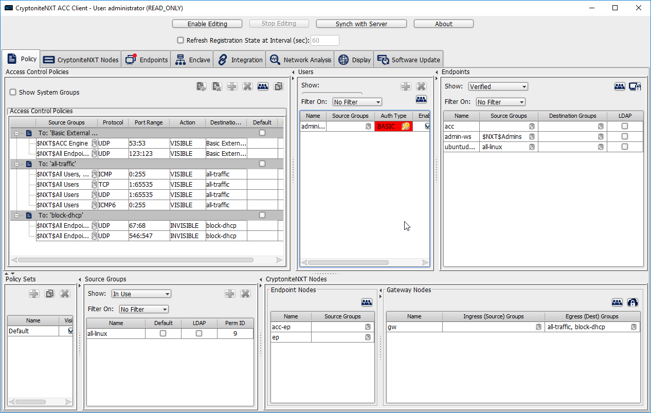
Click Enable Editing at the top of the application.
Click the Endpoints tab.
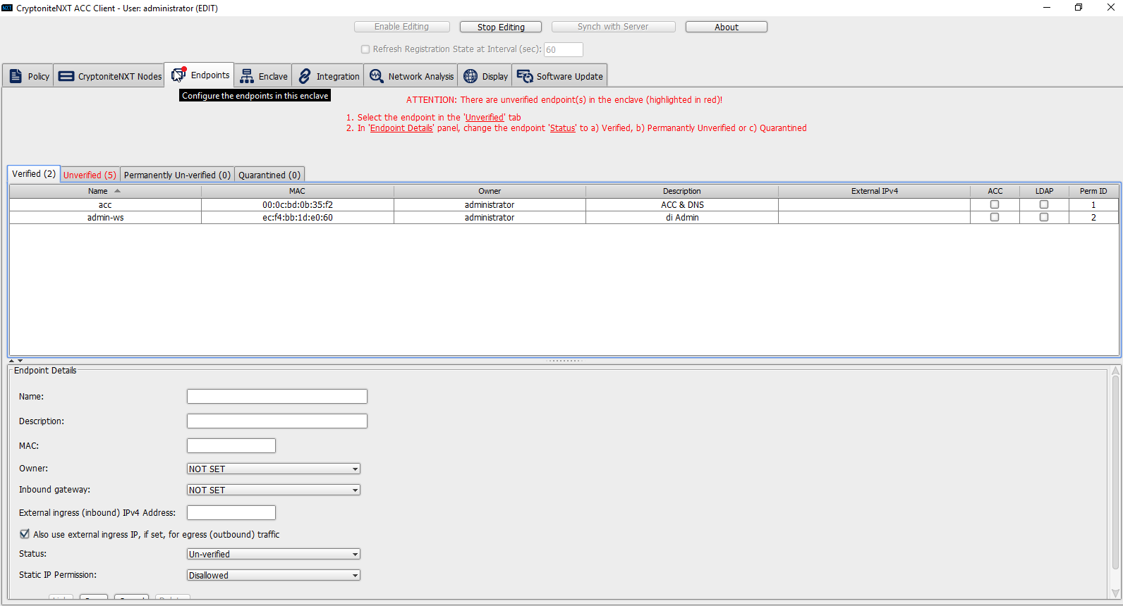
Click the Unverified tab. Any new devices connected to the network should appear here, if configured to use Dynamic Host Configuration Protocol (DHCP).
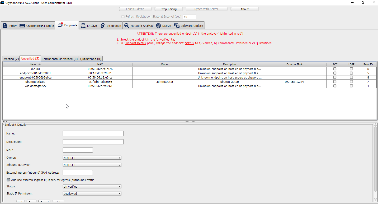
Click the machine to verify.
Enter a name.
Enter a description of the machine.
Select an owner if desired. If not selected, the owner will be the first user to log in to CryptoniteNXT on the machine.
Leave Inbound gateway: as NOT SET to have it choose a default gateway.
Leave External ingress (inbound) IPv4 Address: blank.
Ensure the box next to Also use external ingress IP, if set, for egress (outbound) traffic is checked.
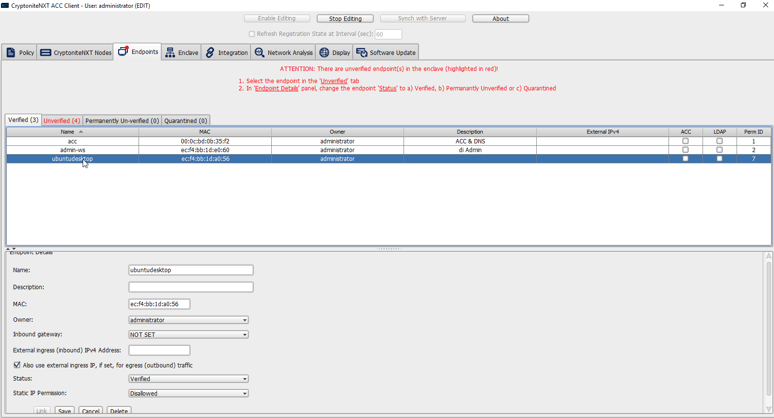
Set Status: to Verified.
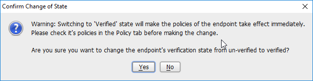
Click Yes.
Click Save.
The machine should now appear in the Verified tab.
2.7.1.2 Create a New User
Go to the Policy tab.
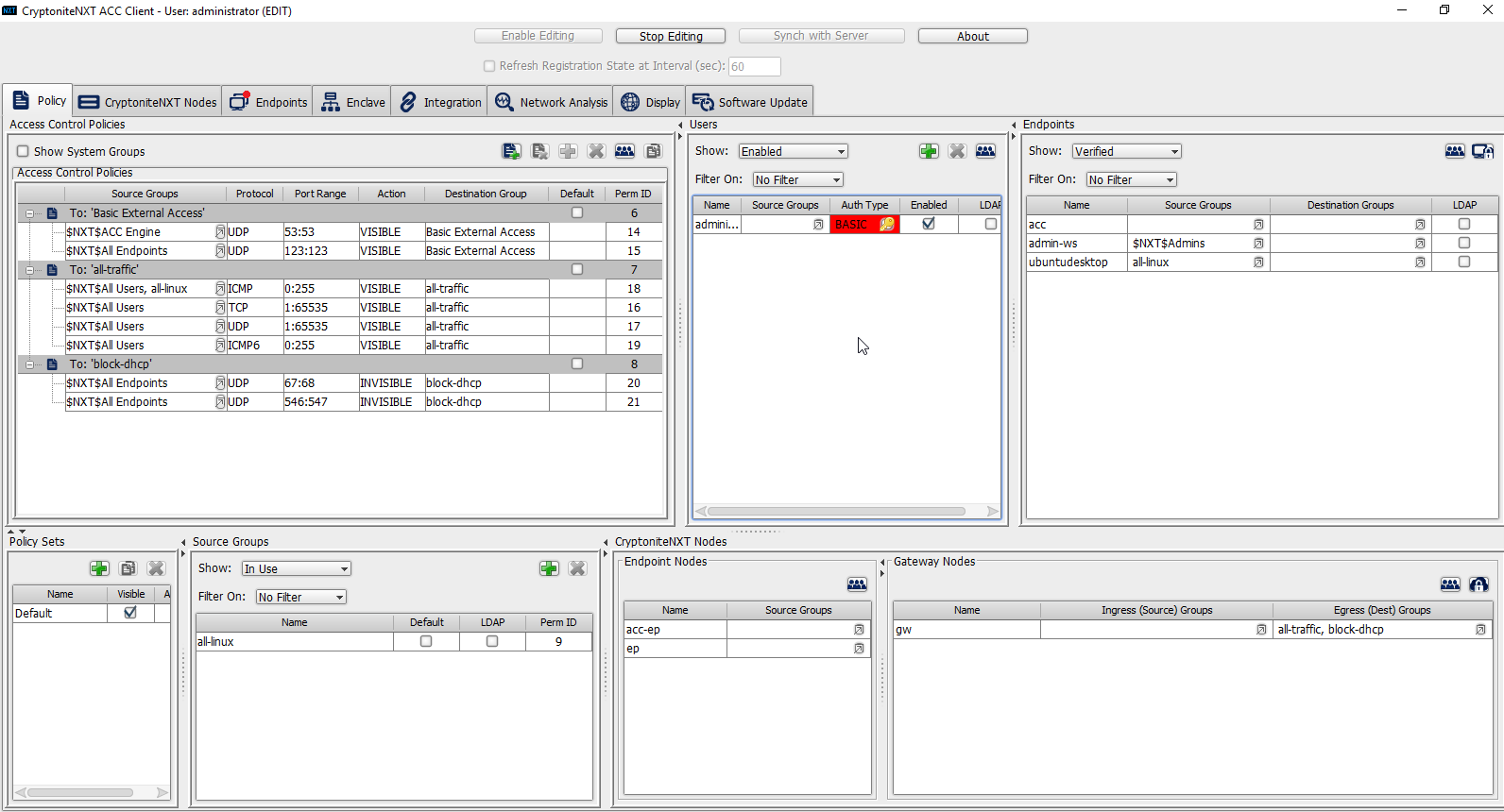
Right-click in the Users window and select New User.
Enter the username, and uncheck the box next to Auto-generate and distribute first user TOTP key to the portal.
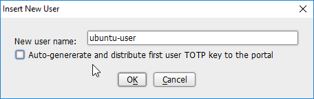
Click OK.
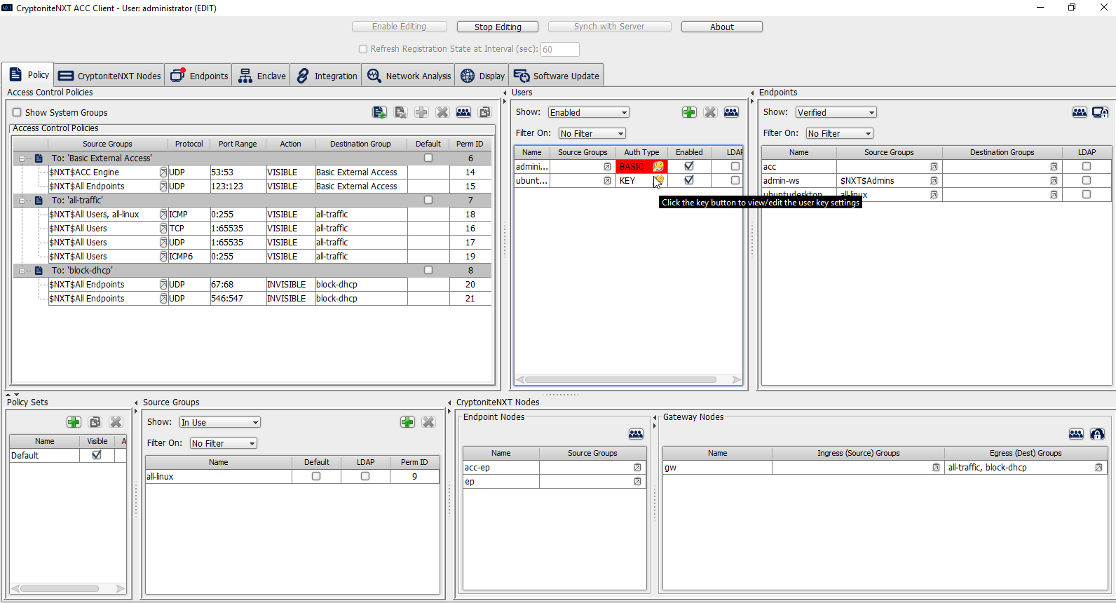
The new user should show up in the Users window. Click the key icon for the newly created user under Auth Type.
Decide on an authentication method for the user. (Note: It is not recommended to use passwords, but as this authentication decision depends on the needs of the organization, passwords are used for the purposes of this practice guide.)
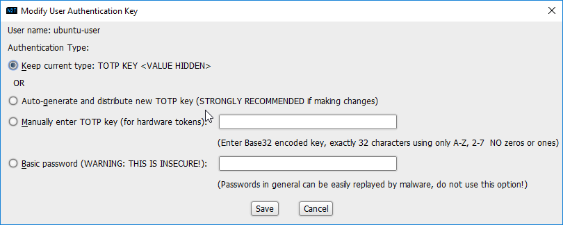
Click Save.
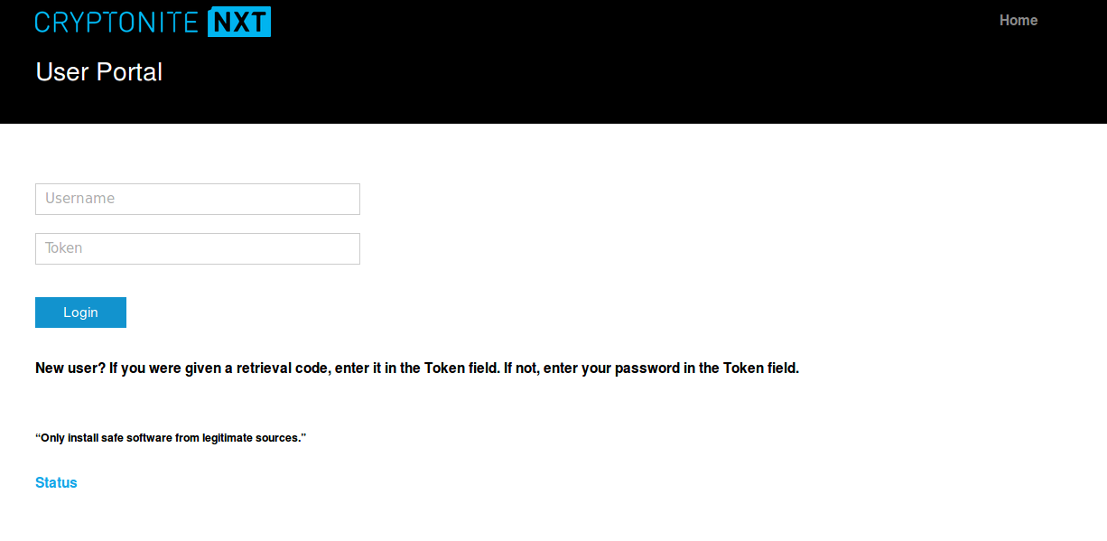
On the client machine, the user should be required to sign in on the CryptoniteNXT portal to access the internet. Authenticate using the newly created user.
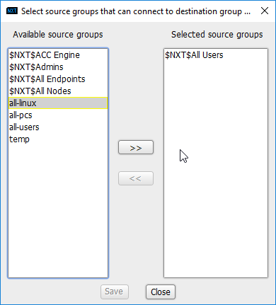
2.7.1.3 Create a New Policy
Creating policy in CryptoniteNXT essentially requires specifying allowed types of traffic. To do this, source groups and destination groups are created.
To create a source group, right-click in the Source Groups window and select New Source Group.
Enter the name of the group.
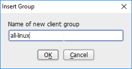
Click OK.
The newly created group should appear in the Source Groups window.
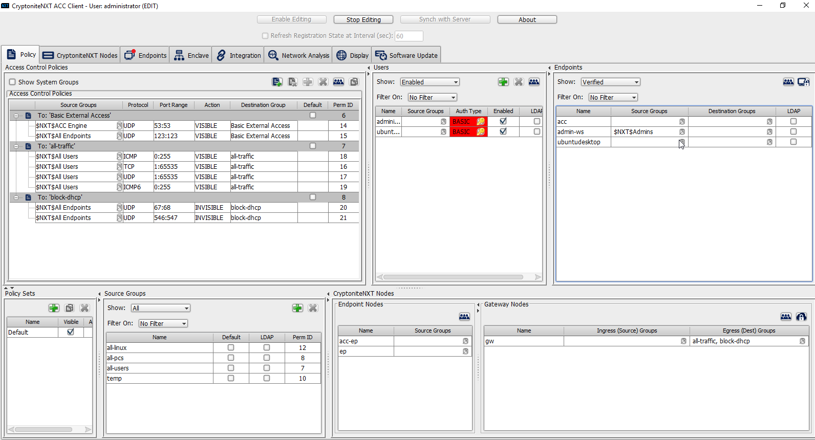
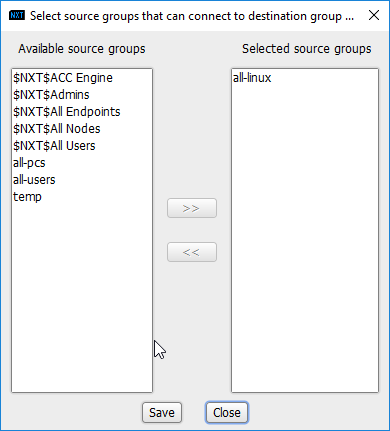
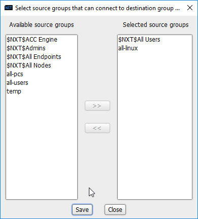
In the Endpoints window, click the arrow button under the Source Groups column for any machines to be added to this Source Group.
Select the newly created group (or groups).
Click the >> button to add the endpoint to this group.
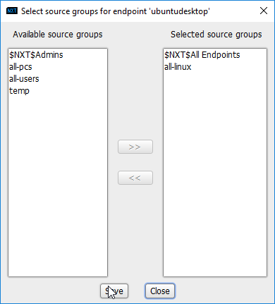
Click Save.
The group should show under the Source Groups column for those endpoints.
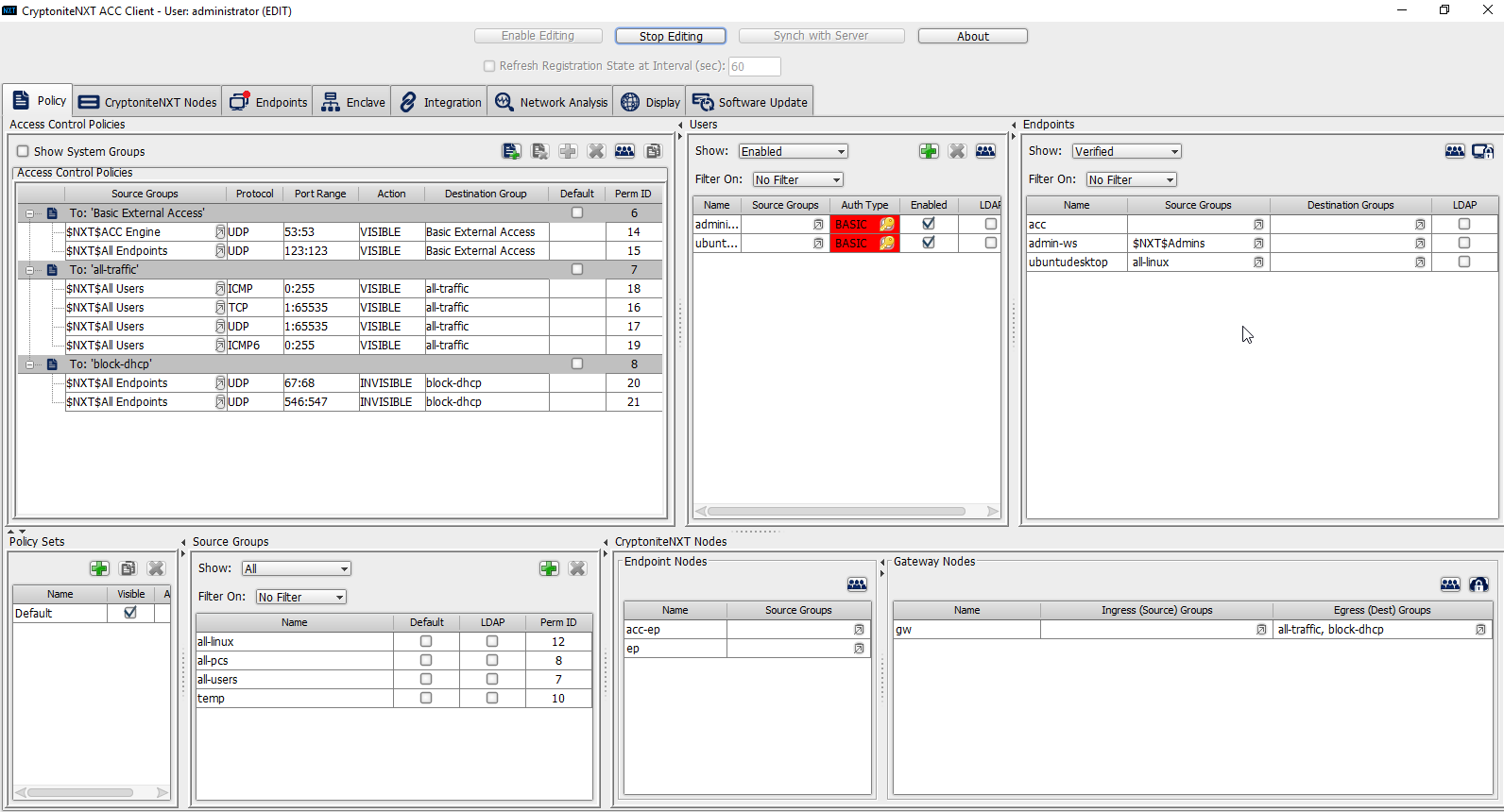
Destination groups are used to govern the allowed destinations of endpoints within certain source groups. While destination groups can be created according to organizational property, this example uses an existing group, all-traffic.
To allow or prevent the use of ping, we add it to the all-traffic group. In the Access Control Policies window, right-click on the row labeled To: ‘all-traffic’ and select New Access Control Policy Entry.
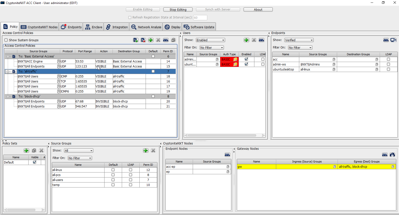
Click the arrow button under the Source Groups column.
Select the newly created source group.
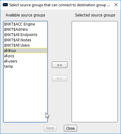
Click the >> button.
Click Save.
Select the Protocol. In this case, to prevent the machine from using ping, we choose ICMP.
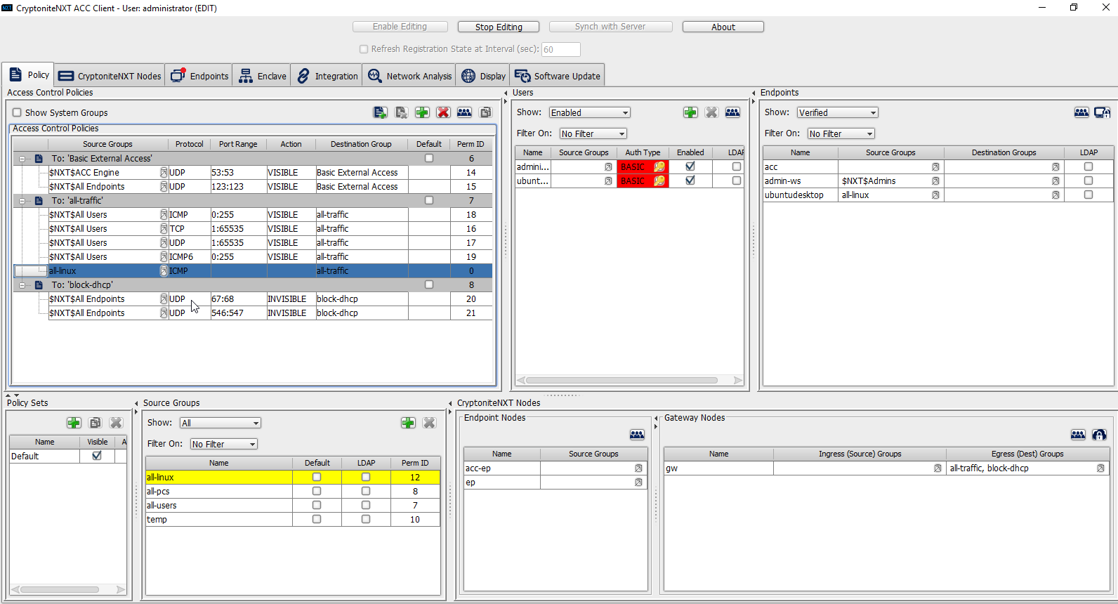
Enter the port range that this traffic can operate on.
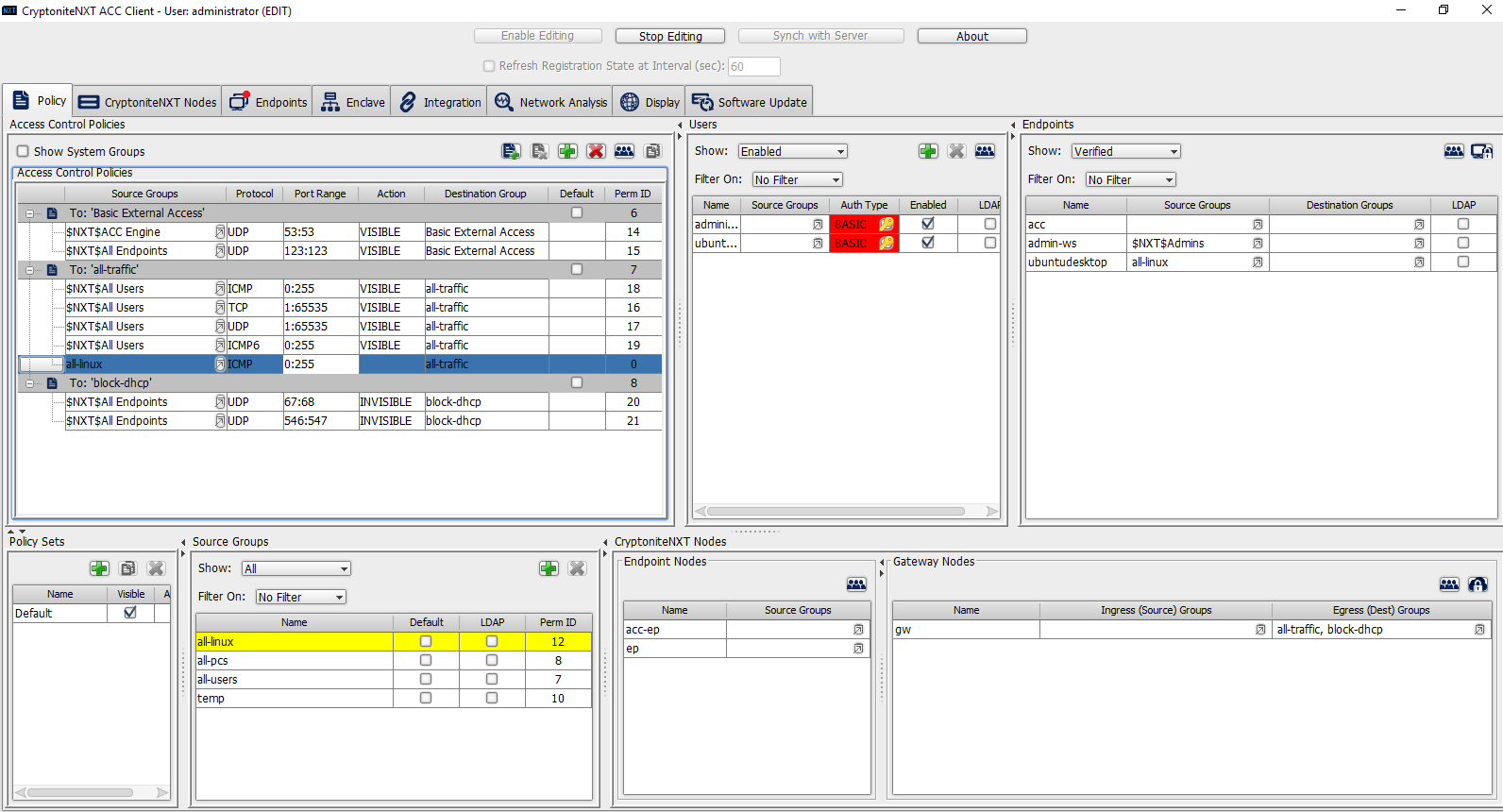
Select INVISIBLE for the Action column.
This will prevent the members of this group from using ping.
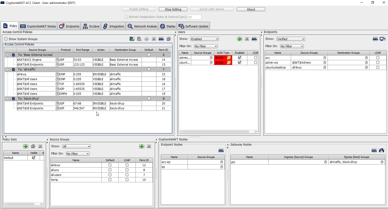
To allow the members of this group to use ping, delete this rule. Right-click the entry and select Delete Access Control Policy Entries.

Add the newly created group to the existing policy entry by clicking the arrow for that entry under Source Groups.
Select the newly created group.
Click the >> button.
Click Save.
Click Stop Editing when finished.
Now, the new machine should be allowed to use ping. With these policies it is possible to manage all traffic through the specification of groups, ports, and protocols.
2.7.2 Integrate CryptoniteNXT with Active Directory
In this section, devices listed in Active Directory will be imported into CryptoniteNXT. For this to be successful, the DNS server must have reverse lookup zones configured for the AD server. Please see Section 2.1.6 for setting up reverse lookup zones on the AD/DNS server.
2.7.2.1 Generate a Keytab File
Open Active Directory Users and Computers.
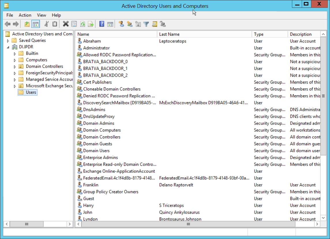
Right-click the Users folder in the left pane and select New > User.
Enter a name for this user, such as nxtadmin.
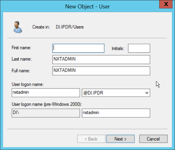
Click Next.
Enter a password for this user, and set the password policy.
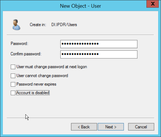
Click Next.
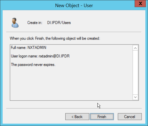
Click Finish.
Right-click the newly created user and select Add to a group….
Enter DnsAdmins.
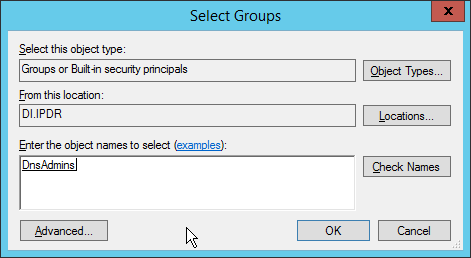
Click OK.
Right-click the Users folder in the left pane and select New > Group.
Enter NXTAdmins as the group name.
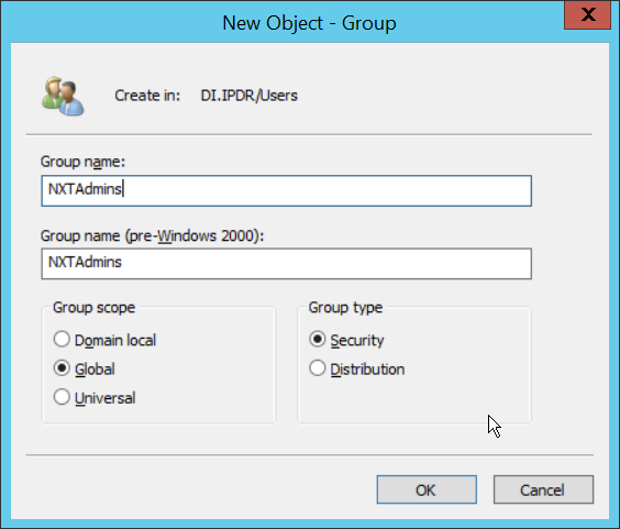
Click OK.
Right-click the Users folder in the left pane and select New > Group.
Enter NXTNodes as the group name.
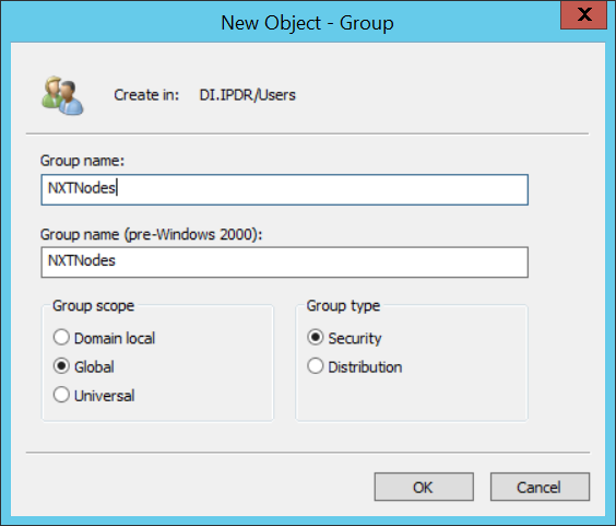
Click OK.
Click Computers in the left pane.
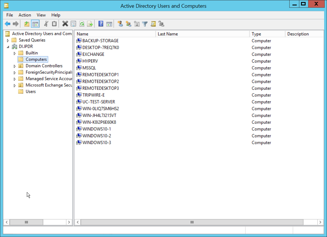
Right-click Computers in the left pane and select New > Computer.
Enter the name of the acc server for CryptoniteNXT (Node A).
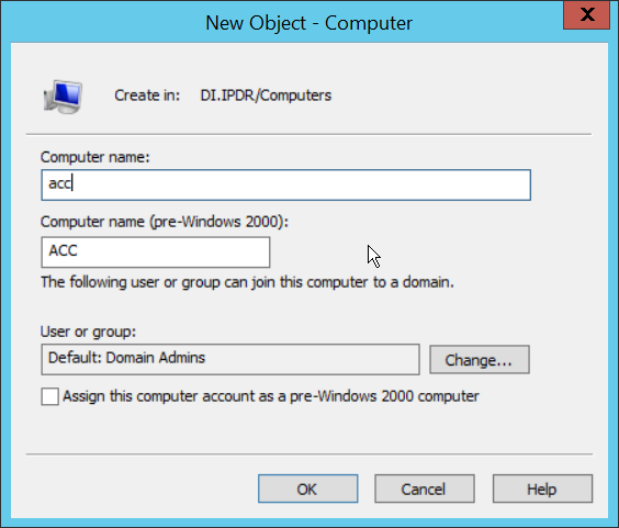
Click OK.
Right-click the newly created computer and select Add to a group….
Enter NXTAdmins in the box labeled Enter the object names to select (examples):.
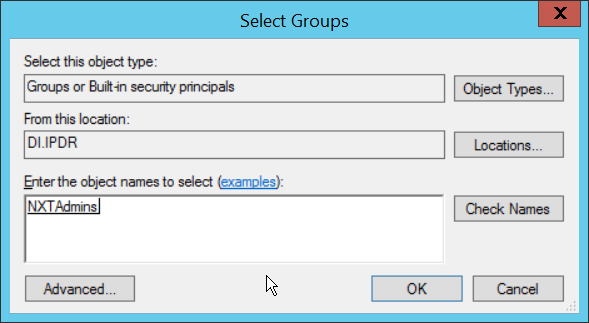
Click OK.
Click OK.
Open a new Administrator PowerShell window.
Enter the following command, using the newly created user in the DnsAdmins group:
> ktpass -princ DNS/<user>.<domain>@<DOMAIN> -mapuser <user>@<domain> -pass <user password> -out .\<keytab filename> -ptype krb5_nt_principal -crypto all
For example:
> ktpass -princ DNS/nxtadmin.di.ipdr@DI.IPDR -mapuser nxtadmin@di.idpr -pass password123 -out .\keytab.out -ptype krb5_nt_principal -crypto all
This will produce a keytab file. Copy this file to the CryptoniteNXT Management workstation.
2.7.2.2 Import Keytab File to ACC
On the management workstation, open the CryptoniteNXT ACC GUI.

Click OK.
Enter the password configured during installation.
Click OK.
Click Enable Editing.
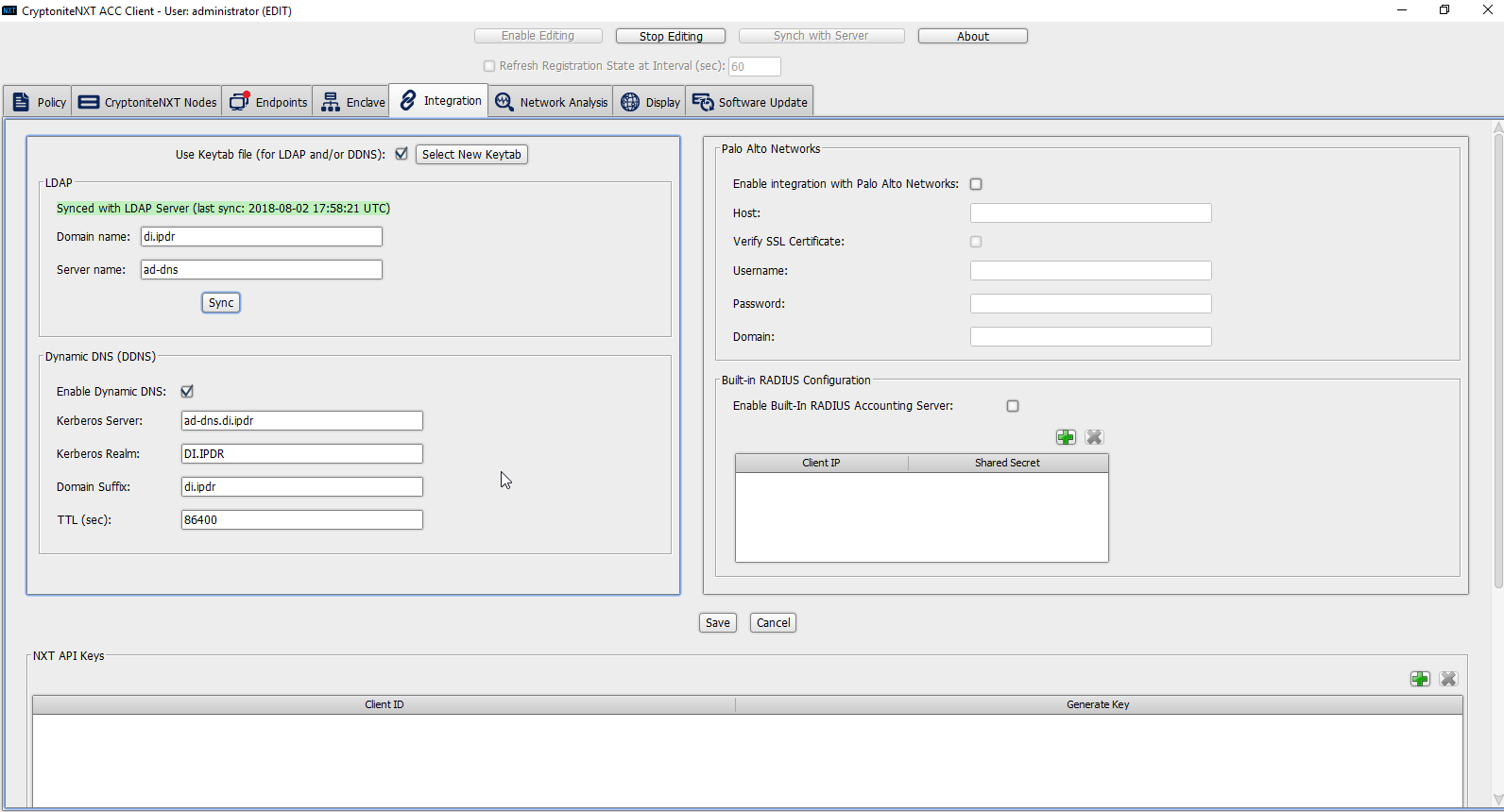
Click the Integration tab.
Check the box next to Use Keytab file (for LDAP and/or DDNS):.
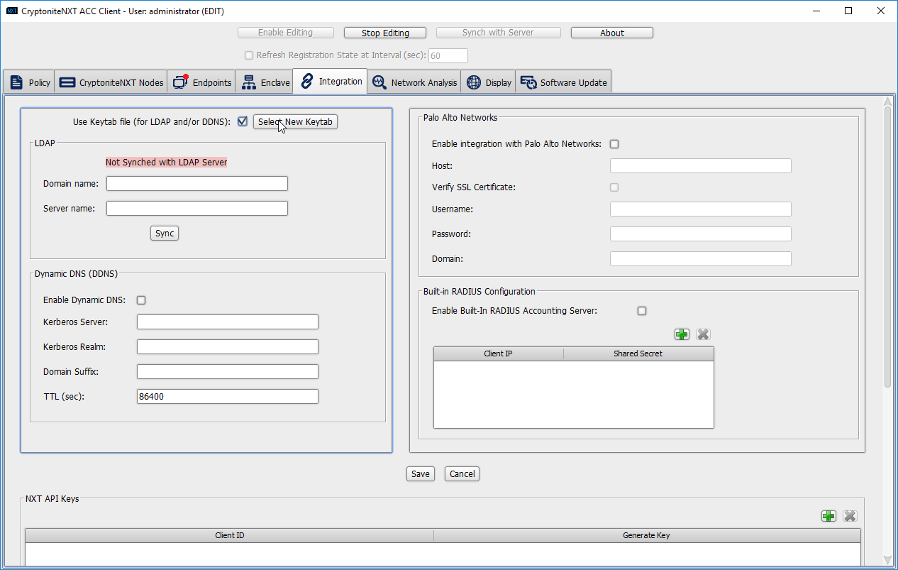
Click Select New Keytab.
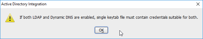
Click OK.
Navigate to the keytab file.
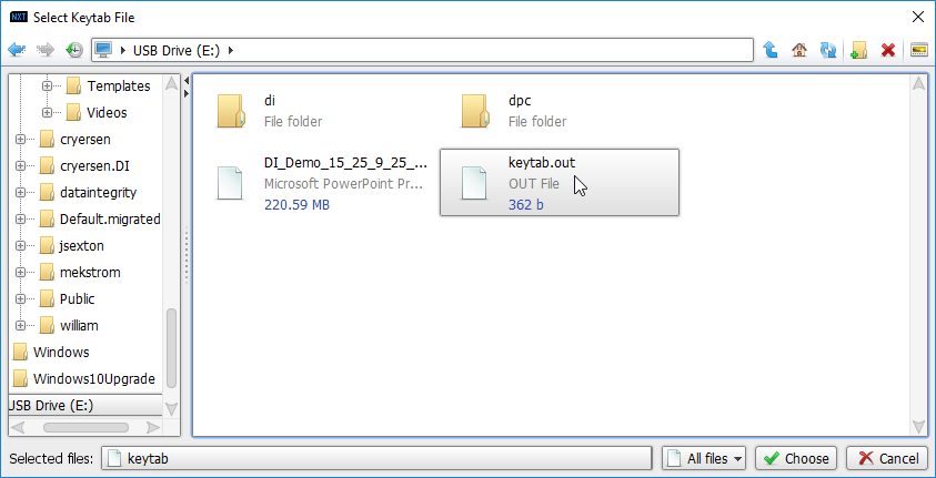
Click Choose.
Click Save.
Under LDAP, enter the Domain name (such as DI.IPDR) and the Server name (such as ad-dns).
Check the box next to Enable Dynamic DNS:.
Enter the fully qualified domain name of the DNS server (such as ad-dns.di.ipdr).
Enter the Kerberos realm (such as DI.IPDR).
Enter the domain suffix (such as di.ipdr).
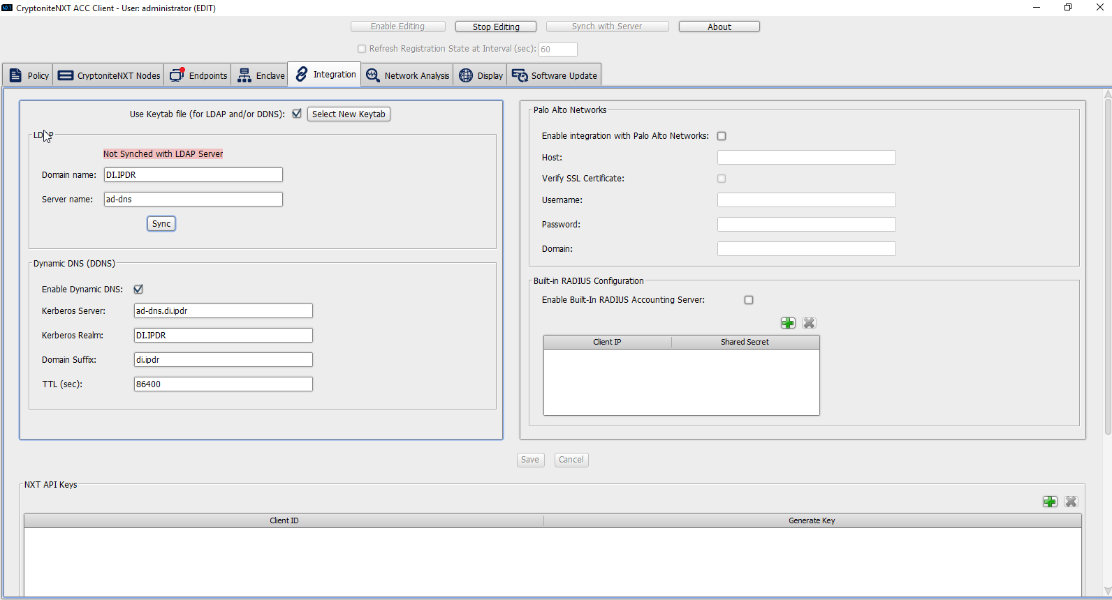
Click Save.
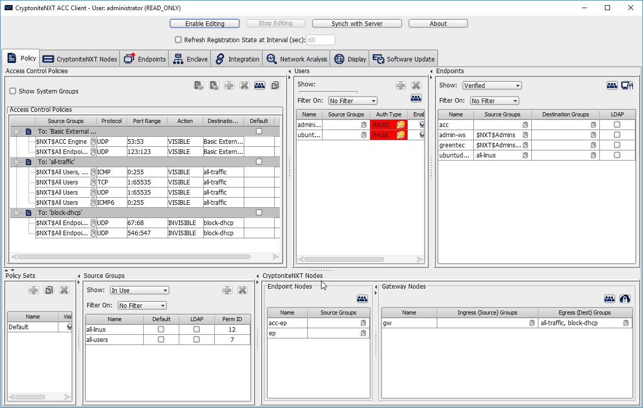
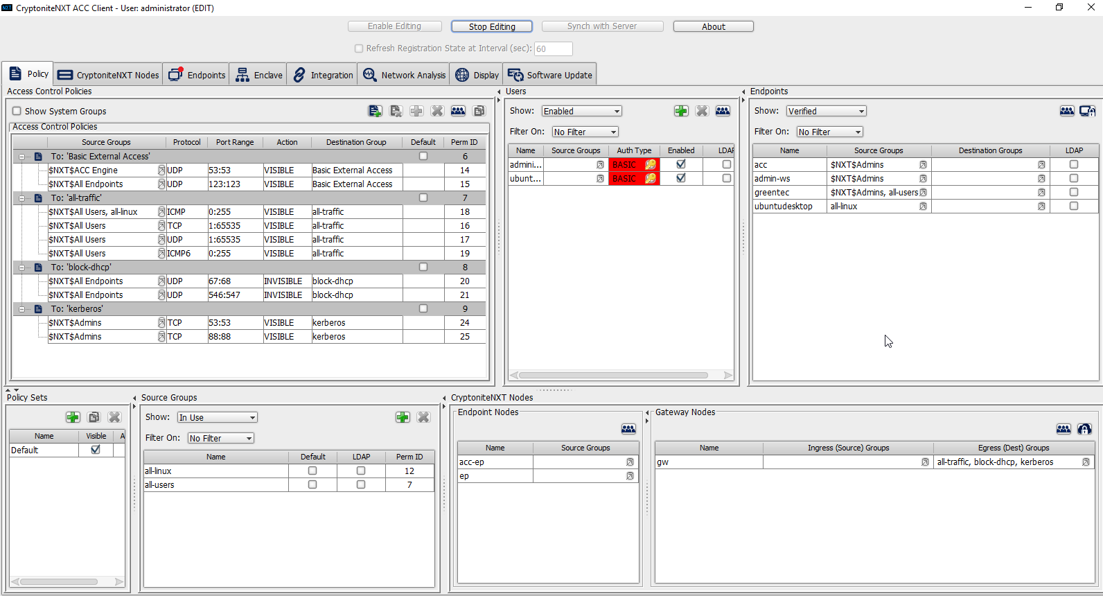
Click the Policies tab.
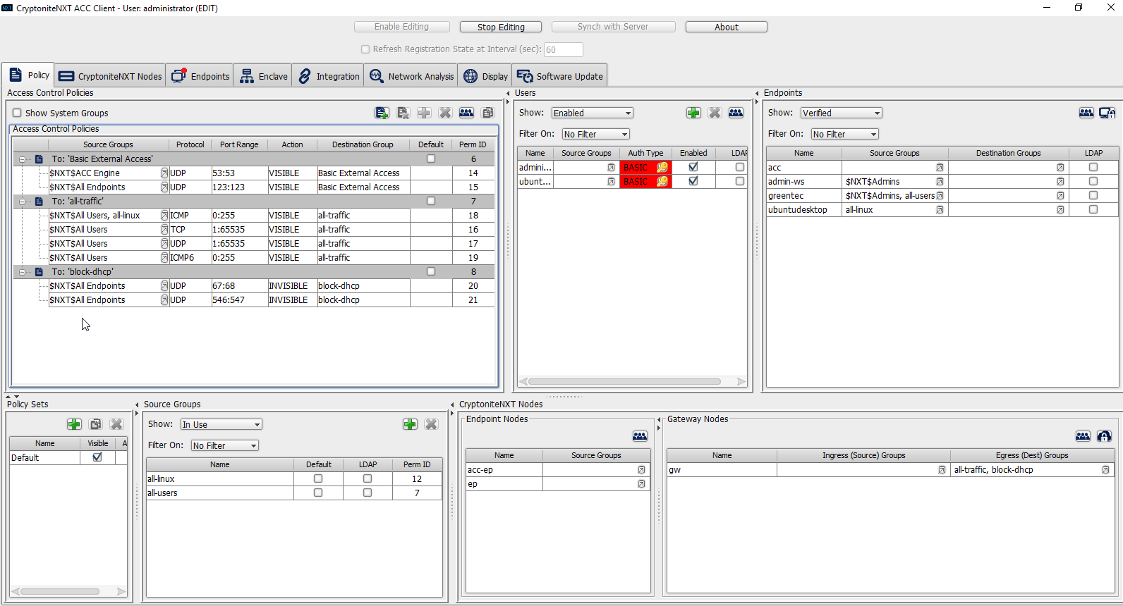
Right-click in the Access Control Policies Window and select New Destination Group.
Enter kerberos.
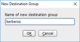
Click OK.
Select TCP under Action.
Enter 53:53 under Port Range.
Select VISIBLE under Action.
Click the arrow under Source Groups.
Select $NXT$Admins.
Click the >> button.
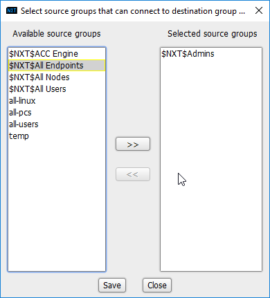
Click Save.
Right-click the To: ‘kerberos’ destination group, and select New Access Control Policy Entry.
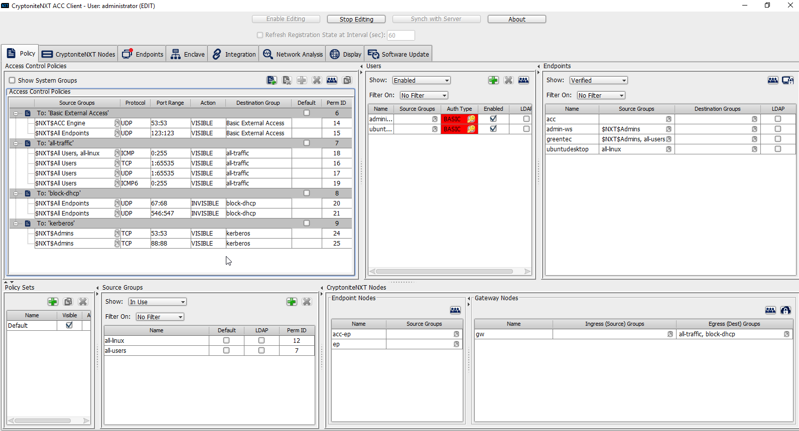
Repeat steps 21–29, but replace 53:53 with 88:88.
In the Gateway Nodes window, click the arrow under Egress (Dest) Groups.
Select “kerberos”.
Click the >> button.
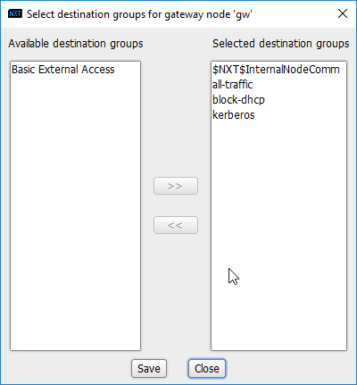
Click Save.
In the Endpoints window, click the arrow under Source Groups associated with the Administration Control Center (ACC).
Select $NXT$Admins.
Click the >> button.
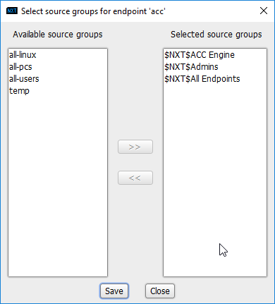
Click Save.
Return to the Integration tab.
Click Sync.
2.8 Backups
For this capability we use an integration of two open-source tools: Duplicati and FileZilla. FileZilla acts as a File Transfer Protocol (FTP) (over TLS) server component, while Duplicati acts as an encrypted backup client. This section details the installation and integration of both tools, as well as the process for creating a backup schedule, but does not provide specific recommendations on backup frequency or backup targets as those are specific to the organization.
2.8.1 FileZilla FTPS Server Setup
Run FileZilla_Server-0_9_60_2.exe.

Click I Agree.
Select Standard from the drop-down menu.
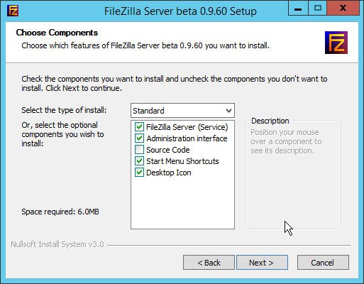
Click Next.
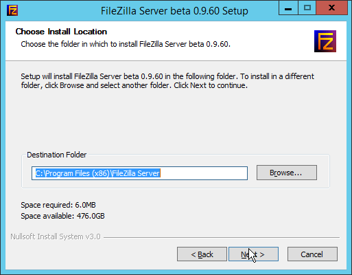
Click Next.
Select Install as service, started with Windows (default) from the drop-down.
Specify a port (for the administrator interface to run on) if desired (the default is 14147).
Ensure the box next to Start Server after setup completes is checked.
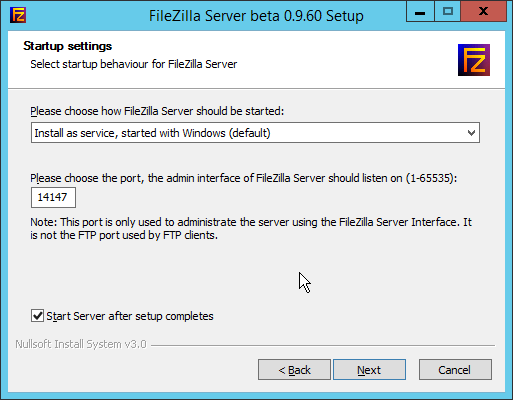
Click Next.
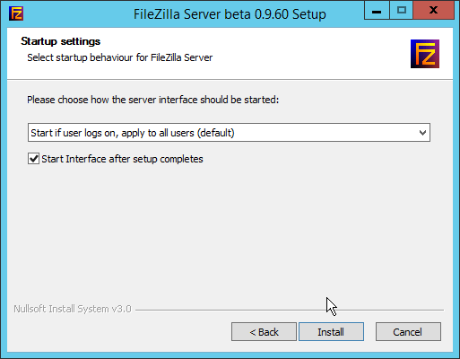
Click Install.
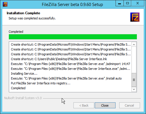
Click Close.
2.8.2 FileZilla Configuration
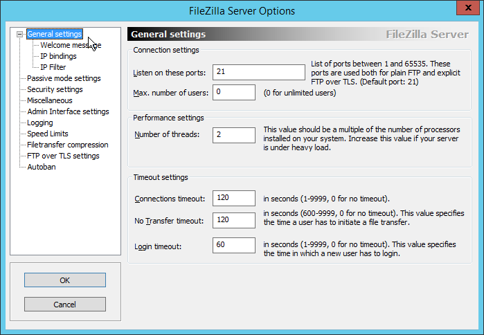
When the administrator interface comes up, ensure that the port is correct and click Connect.
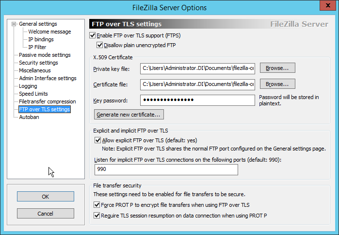
Click Edit > Settings.
Click FTP over TLS settings.
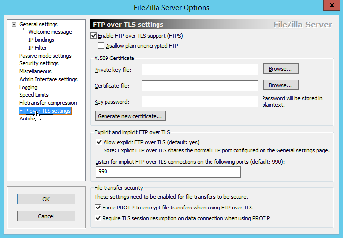
Check the box next to Enable FTP over TLS support (FTPS).
Check the box next to Disallow plain unencrypted FTP.
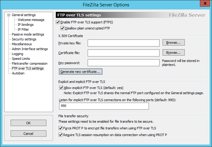
Click Generate new certificate.
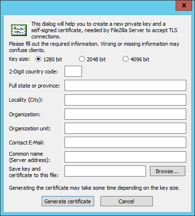
Select 4096 bit for Key Size.
Enter the information for the certificate specific to your organization.
For the common name, enter the address of the server on which this is installed.
Click Browse and specify a file location for the certificate.
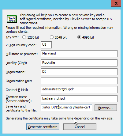
Click Generate certificate. (The file now contains both the private key and the certificate. These can be separated, for ease of use, as long as the correct file locations are specified in the settings.)
Click OK.

Enter a password for the key.
Ensure the box next to Force PROT P to encrypt file transfers when using FTP over TLS is checked.
Ensure the box next to Require TLS session resumption on data connection when using PROT P is checked.
Click Passive mode settings. Check the box next to Use custom port range. (This is necessary in cases of a local server behind Network Address Translation (NAT) or a firewall.)
Enter a range of ports for passive mode to use. Ensure that these ports are allowed through the firewall.
Select Use the following IP.
Enter the server address.
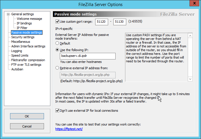
Click OK.
2.8.3 Add a User to FileZilla
In the FileZilla administrator interface, click Edit > Users.
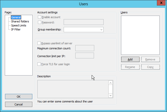
Click Add.
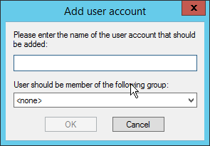
Enter a name for the user.
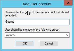
Click OK.
Check the box next to Password.
Enter a password for the user.
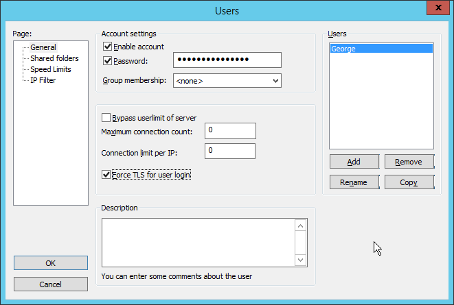
Check the box next to Force TLS for user login.
Click Shared Folders.
Click Add, under Shared Folders.
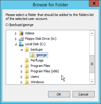
Select a place for backups for this user to be stored.
Check the boxes next to Write and Append, under Files.
Check the box next to Create, under Directories.
Select this entry and click Set as home dir.
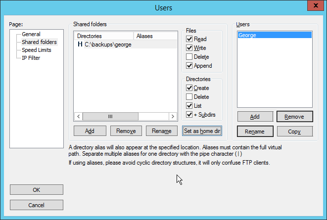
Click OK.
2.8.4 Duplicati Client Installation (Windows)
On the client machine, run duplicati-2.0.3.3_beta_2018-04-02-x64.msi.
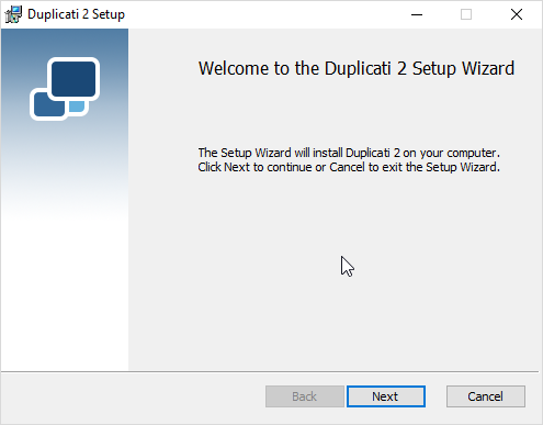
Click Next.
Check the box next to I accept the terms in the License Agreement.
Click Next.
Click Next.
Click Install.
Click Finish.
Start Duplicati by going to localhost:8200.
2.8.5 Duplicati Client Installation (Ubuntu)
Install mono by using the following command:
> sudo apt install mono-runtimeDownload the Duplicati package by running the following command:
> wget https://github.com/duplicati/duplicati/releases/download/v2.0.3.9-2.0.3.9_canary_2018-06-30/duplicati_2.0.3.9-1_all.deb
Install Duplicati by using the following command:
> sudo dpkg -i duplicati_2.0.3.9-1_all.debRun Duplicati as a service by running the following command:
> sudo systemctl enable duplicati
2.8.6 Configure Duplicati
When it first starts, Duplicati will have a First run setup.
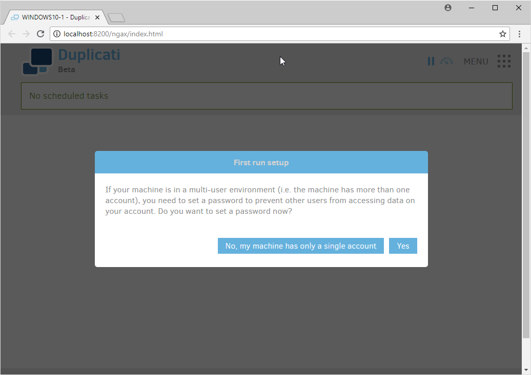
Click Yes.
Check the box next to Password.
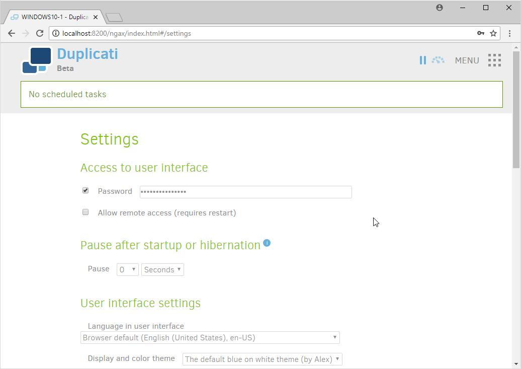
Enter a password.
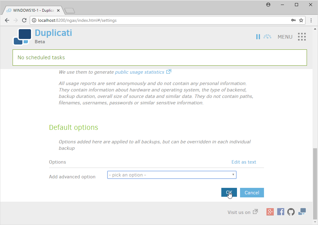
Click OK.
On the home page, click Add backup.
Select Configure a new backup.
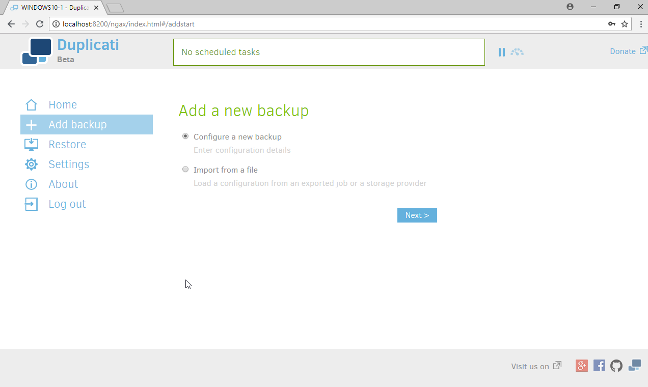
Click Next.
Enter a name for the backup.
Select AES-256 encryption, built in from the drop-down menu.
Enter a password.
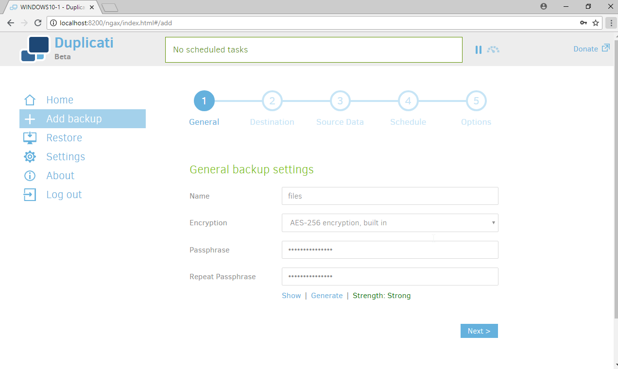
Click Next.
Select FTP for Storage Type.
Check the box next to Use SSL.
Enter the server name and port (default: 21) of the server running FileZilla.
Enter a path for the backup to be stored in (within the specified shared directory of the user).
Enter the username and password created for FileZilla.
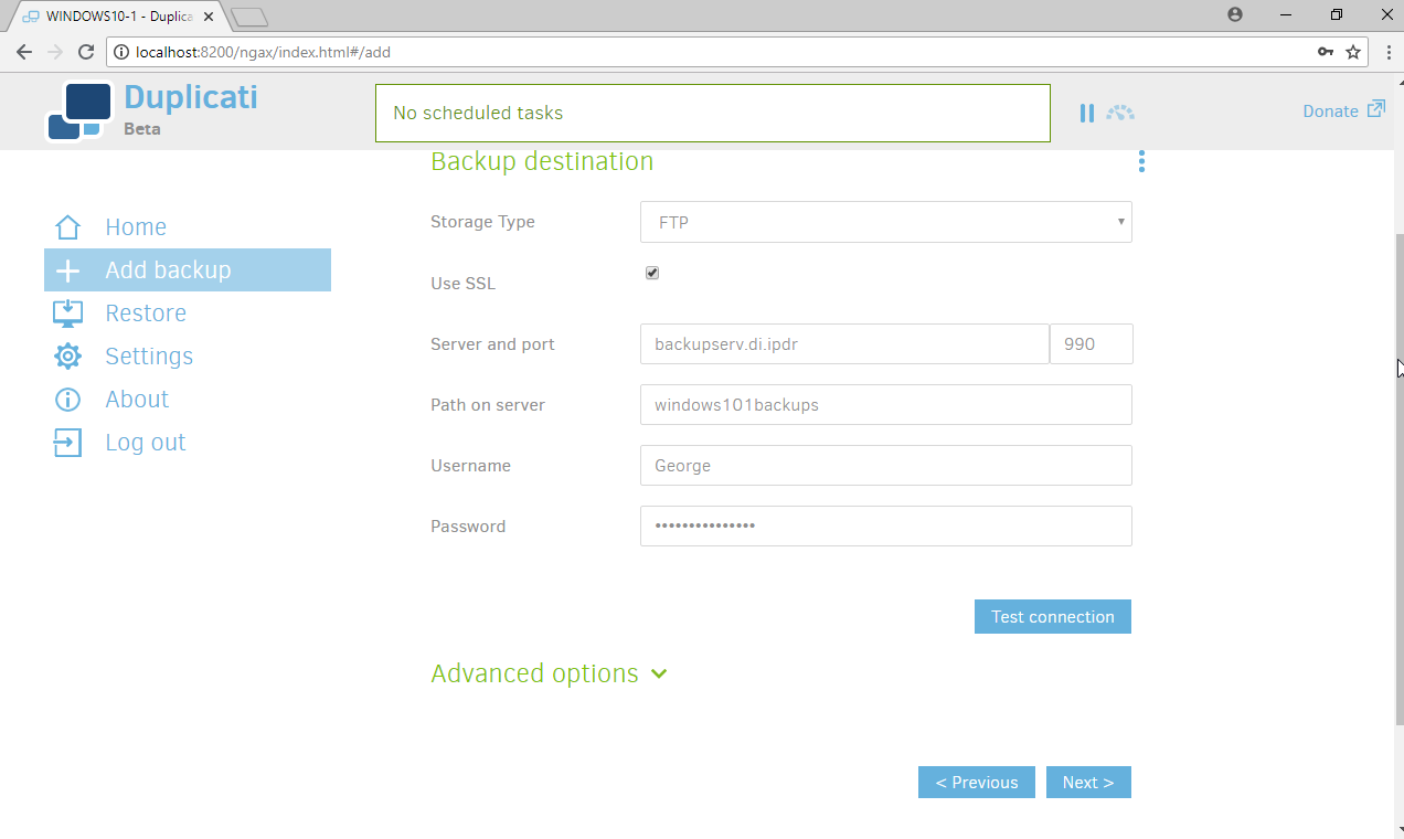
Click Test Connection (if the connection fails, ensure that the port is allowed in your server’s firewall).
If you receive an error about a certificate, you can go to Advanced Options, select accept-specified-ssl-hash, and enter the thumbprint from the server’s certificate.
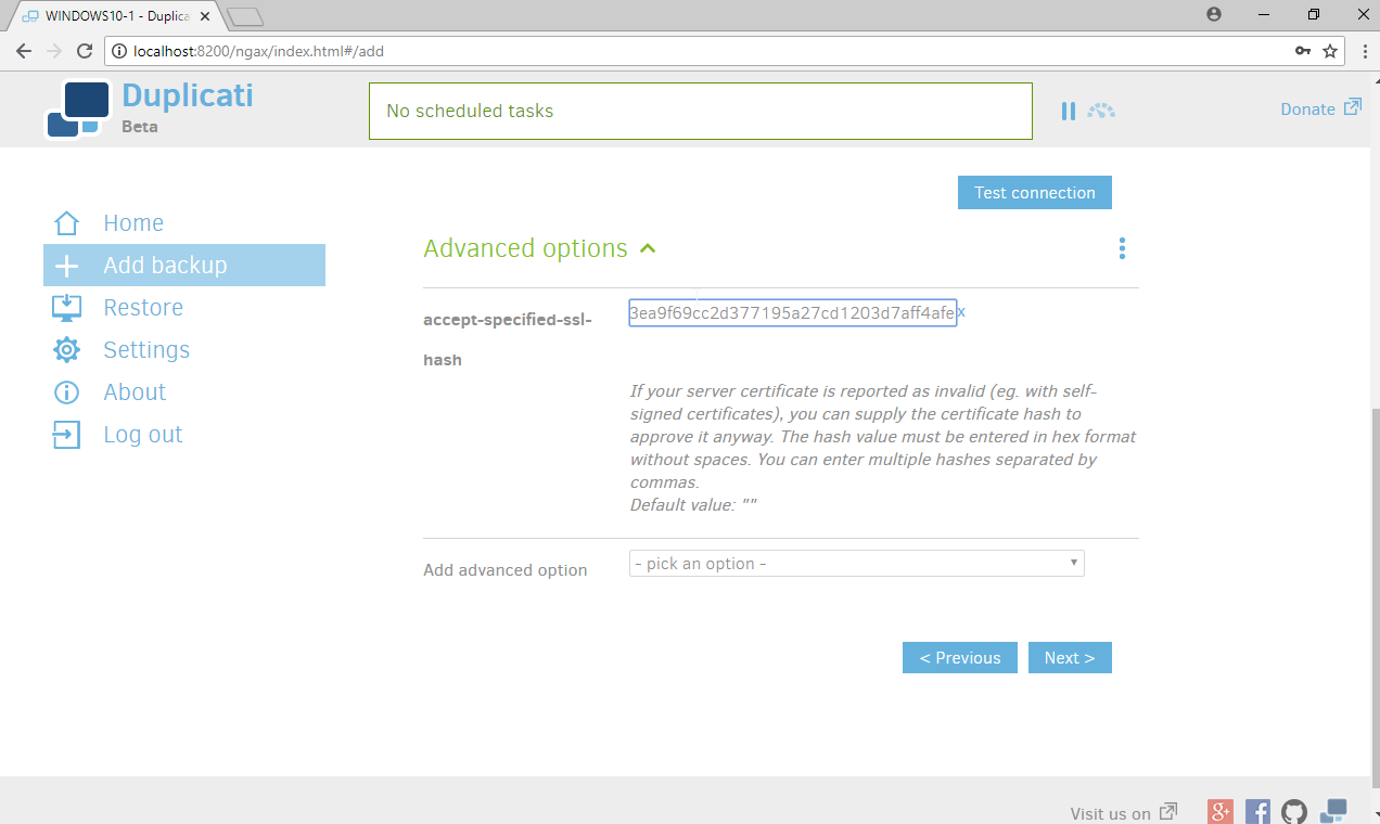
Click Next.
Select the folders on the local machine to be backed up to the server according to your organization’s needs.
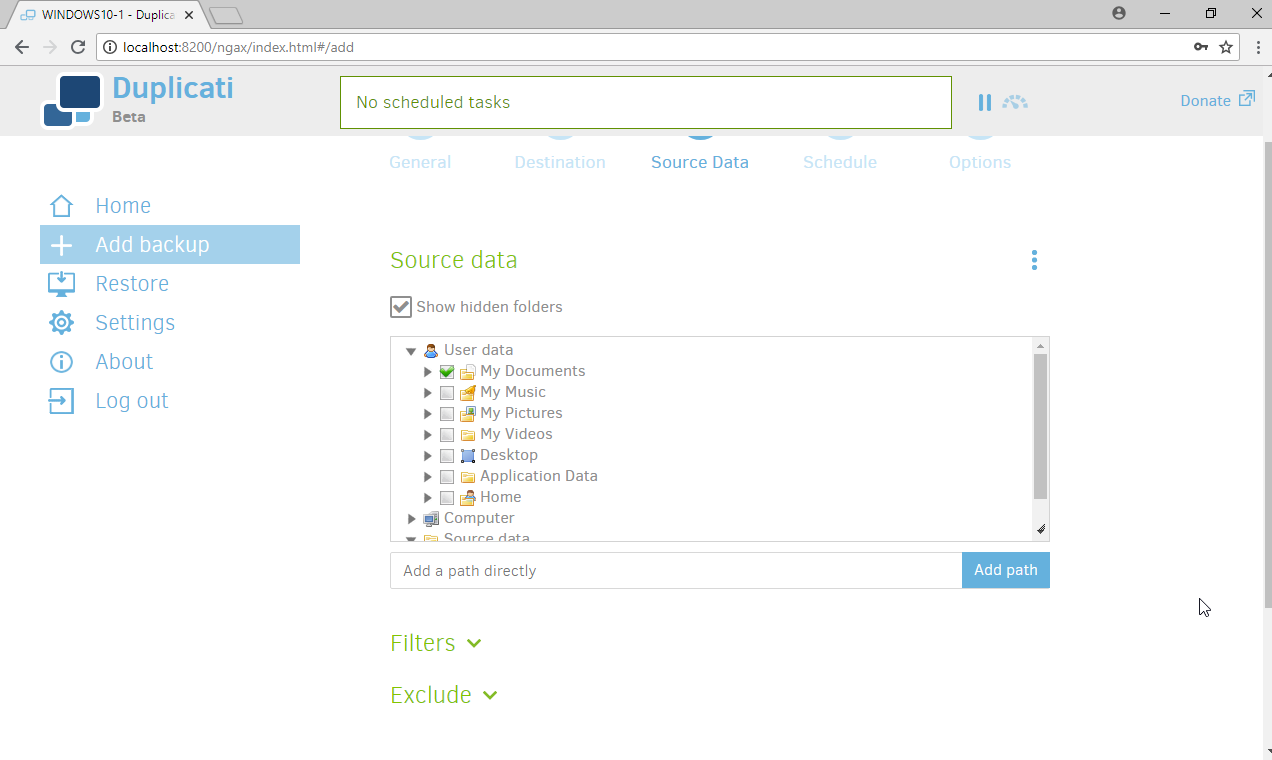
Click Next.
Select a backup schedule according to your organization’s needs.
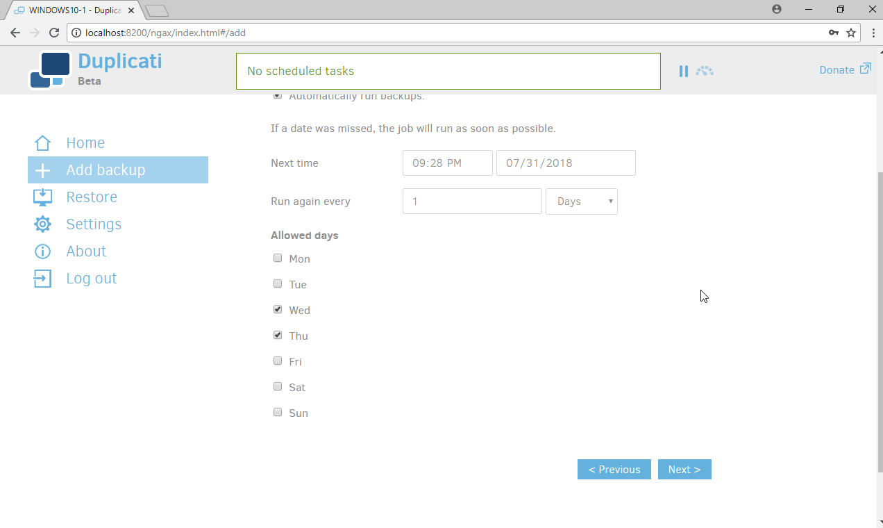
Click Next.
Select any other options according to your organization’s needs.
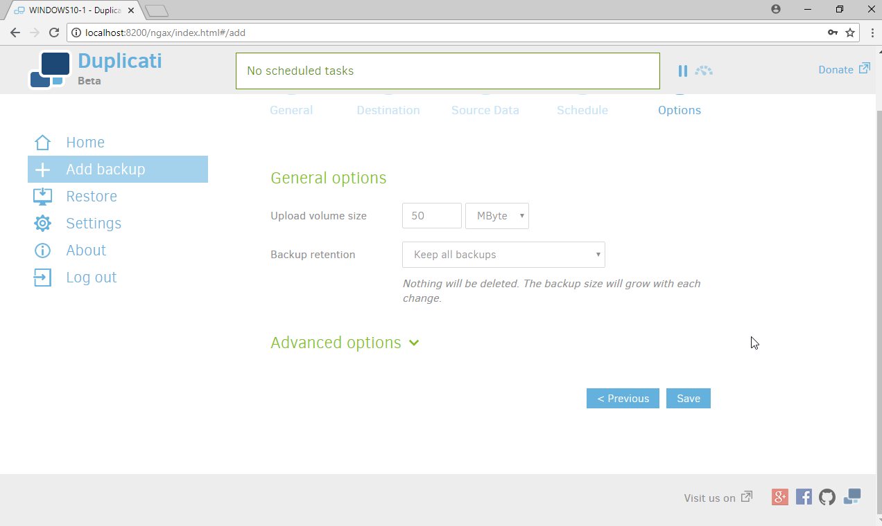
Click Save.
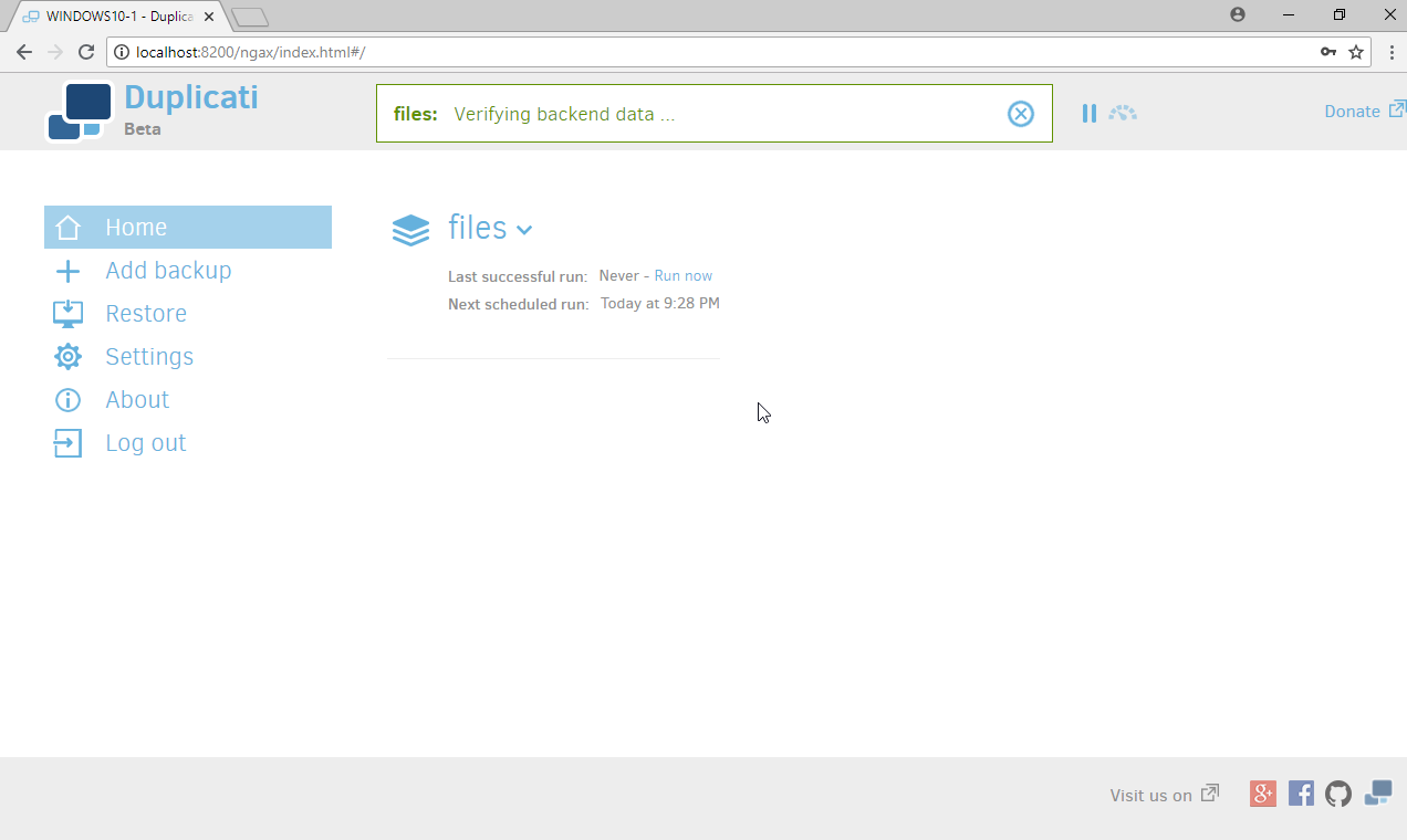
When finished, you can choose to Run now to start a backup immediately.
2.9 Semperis Active Directory Forest Recovery
This section details the installation of Semperis Active Directory Forest Recovery (ADFR), a tool used for backing up and restoring Active Directory forests. This installation requires both a copy of SQL Server Express as well as the Semperis Wizard. See the Semperis ADFR v2.5 Technical Requirements document for specifics on the requirements. For a Windows Server 2012 R2 installation, simply meet the following requirements:
.NET Framework Version 3.5 SP1
.NET Framework Version 4.5.2 or later
not joined to the Active Directory domain it is protecting
SQL Express is not installed on the machine, but the installer SQLEXPR_x64_ENU.exe is downloaded.
2.9.1 Install Semperis ADFR
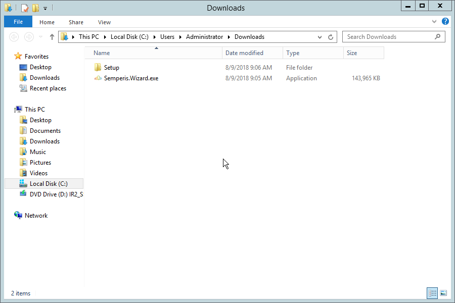
Place the SQLEXPR_x64_ENU.exe installer in a directory called Setup, and ensure that the Semperis Wizard is adjacent to the Setup folder (not inside it).
If prompted to restart the computer, do so.
Click I Agree.
Select Evaluation License.
Select Active Directory Forest Recovery.
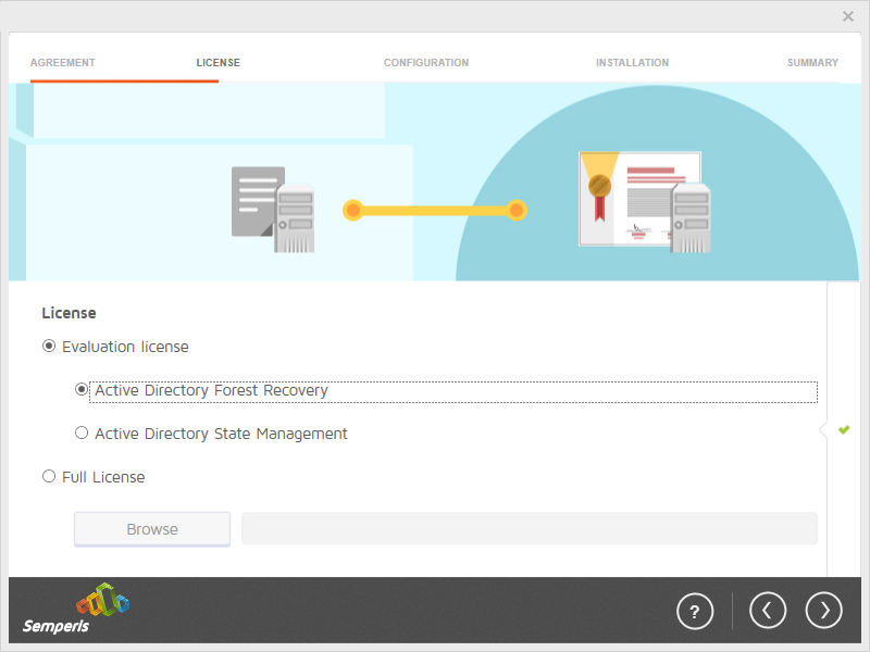
Click the > button.
Click OK.
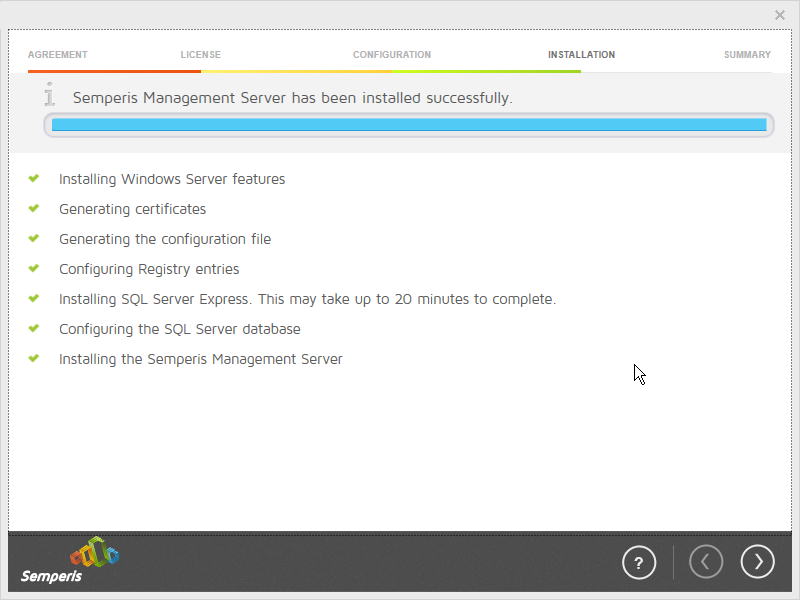
Wait for the installation to complete.
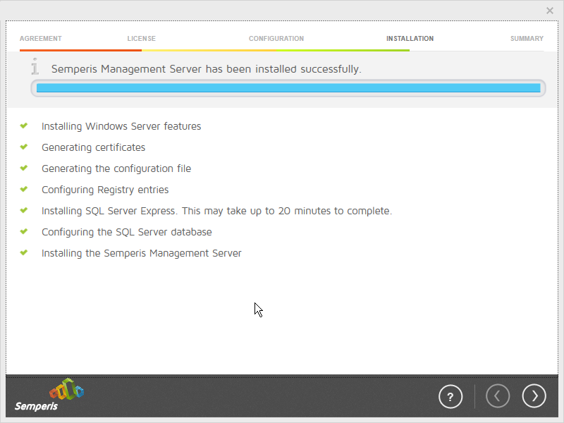
Click the > button.
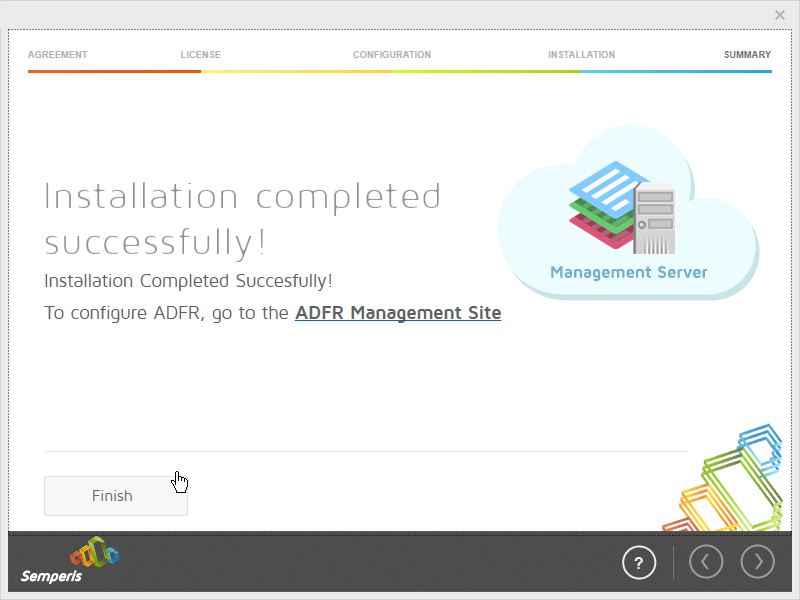
Click Finish.
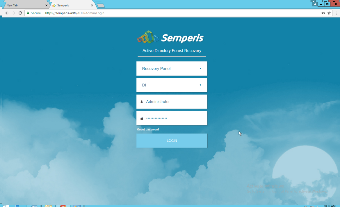
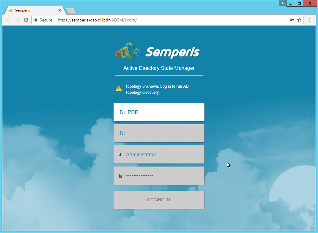
There should now be a shortcut on the desktop linking to the web console for Semperis ADFR.
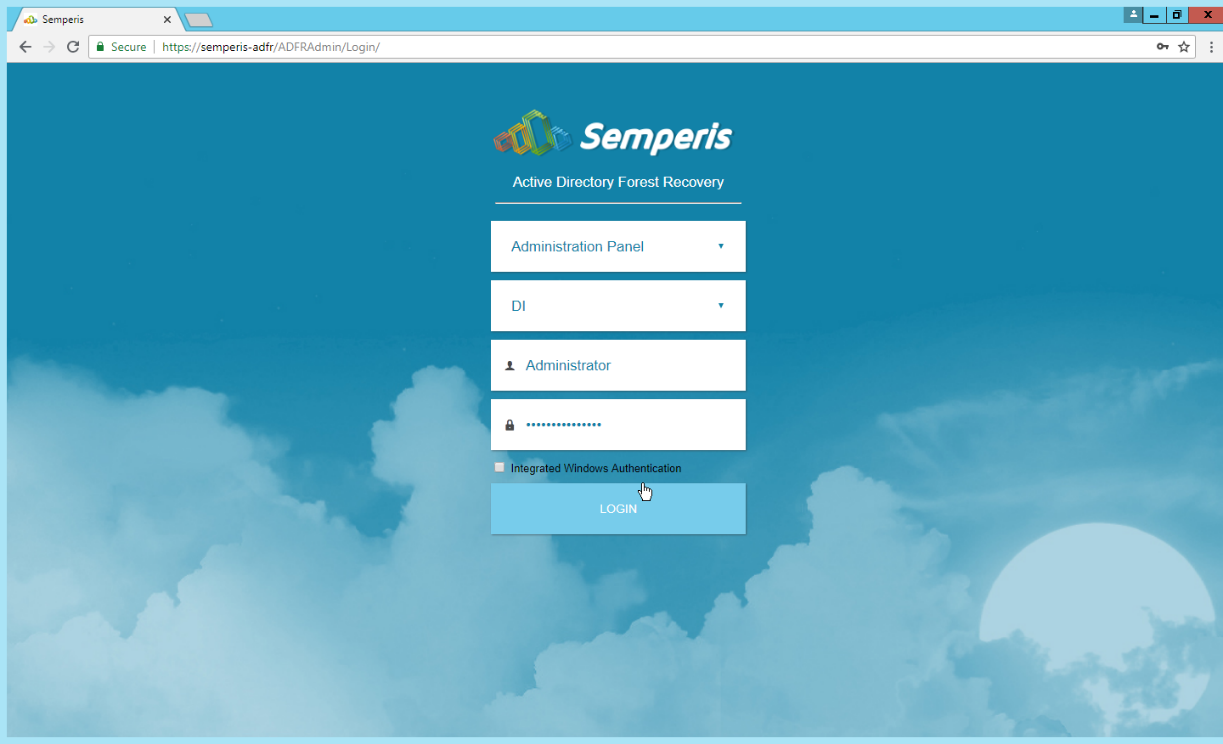
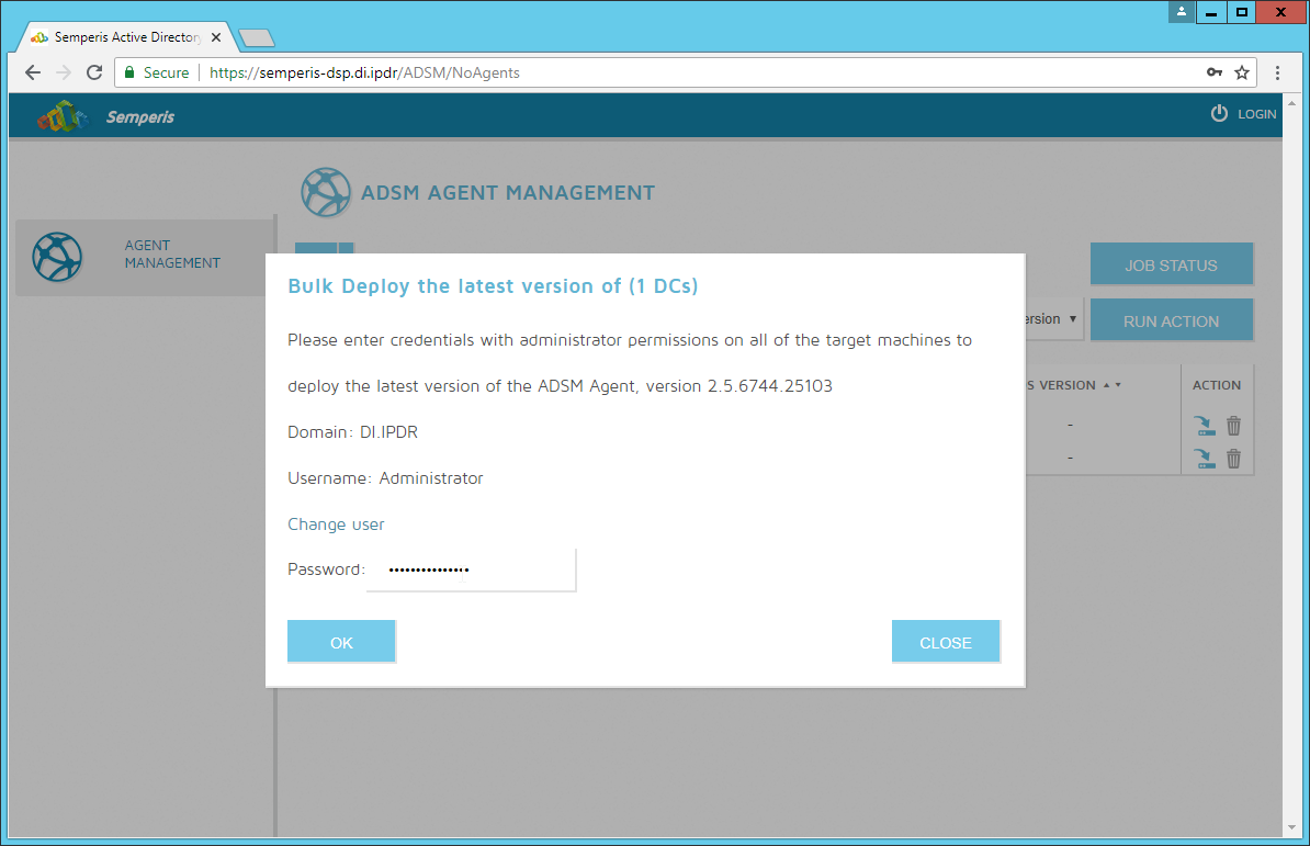
On the login page, enter the full domain as well as the NetBIOS name.
Enter the username and password of an administrator on the domain.
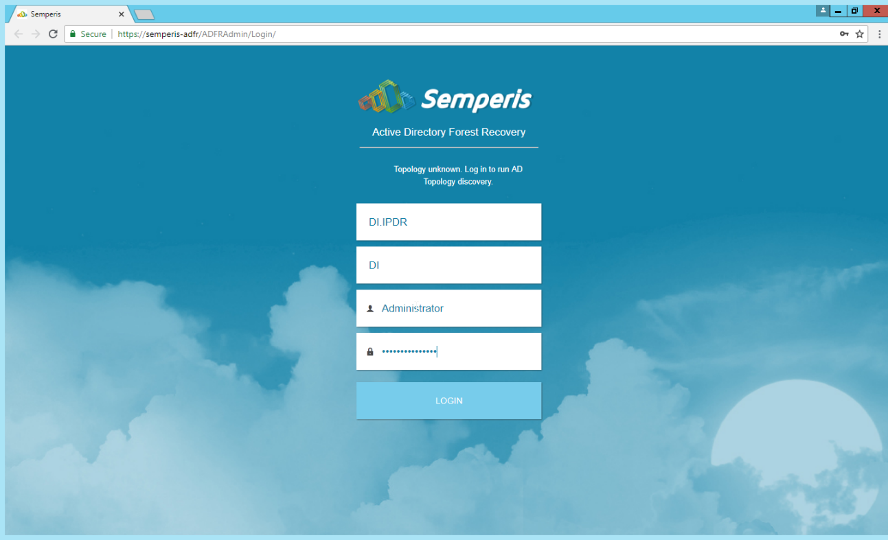
Click Login.
Check the box next to any domain controllers that should be backed up.
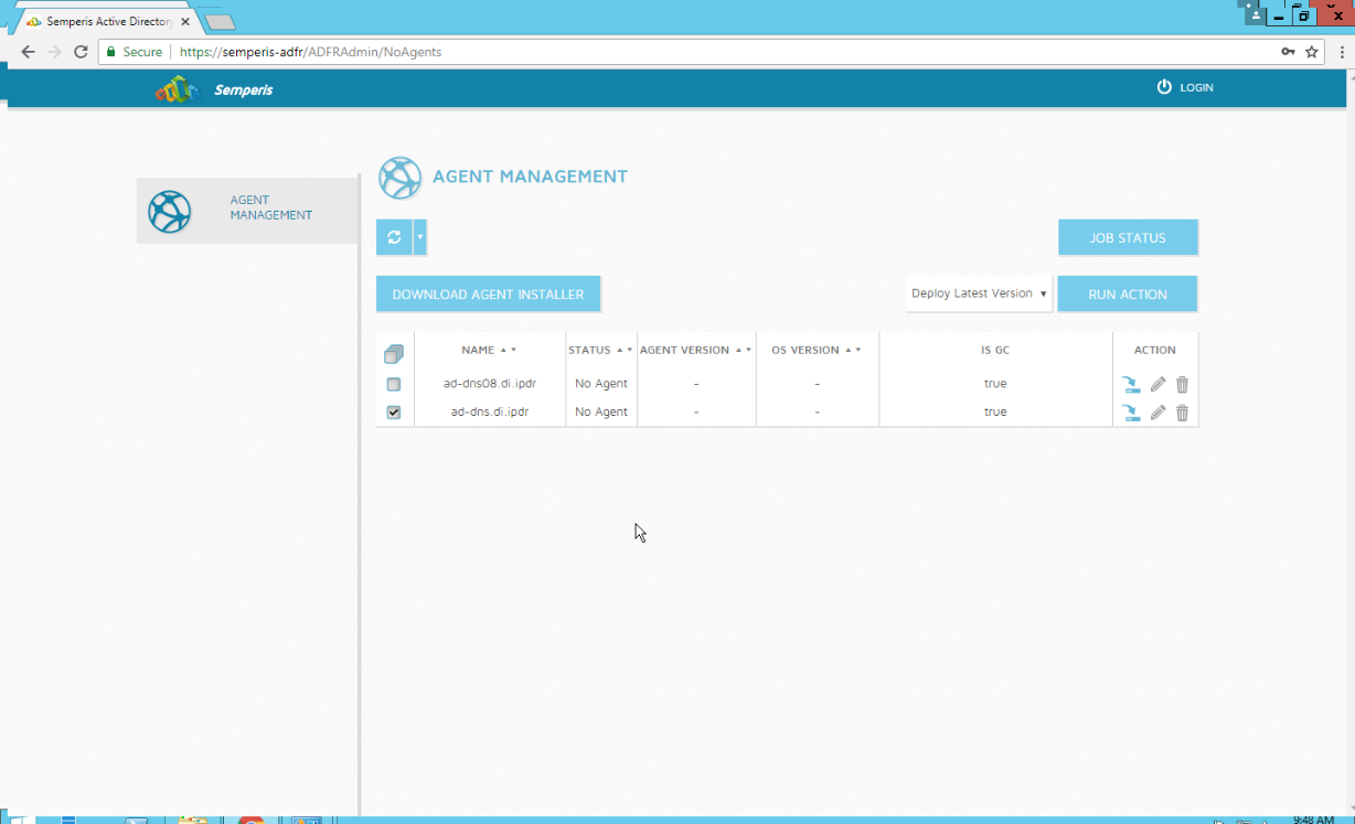
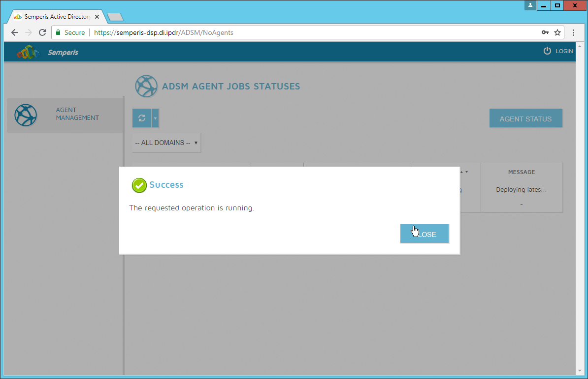
Click Run Action.
Enter the password in the prompt.
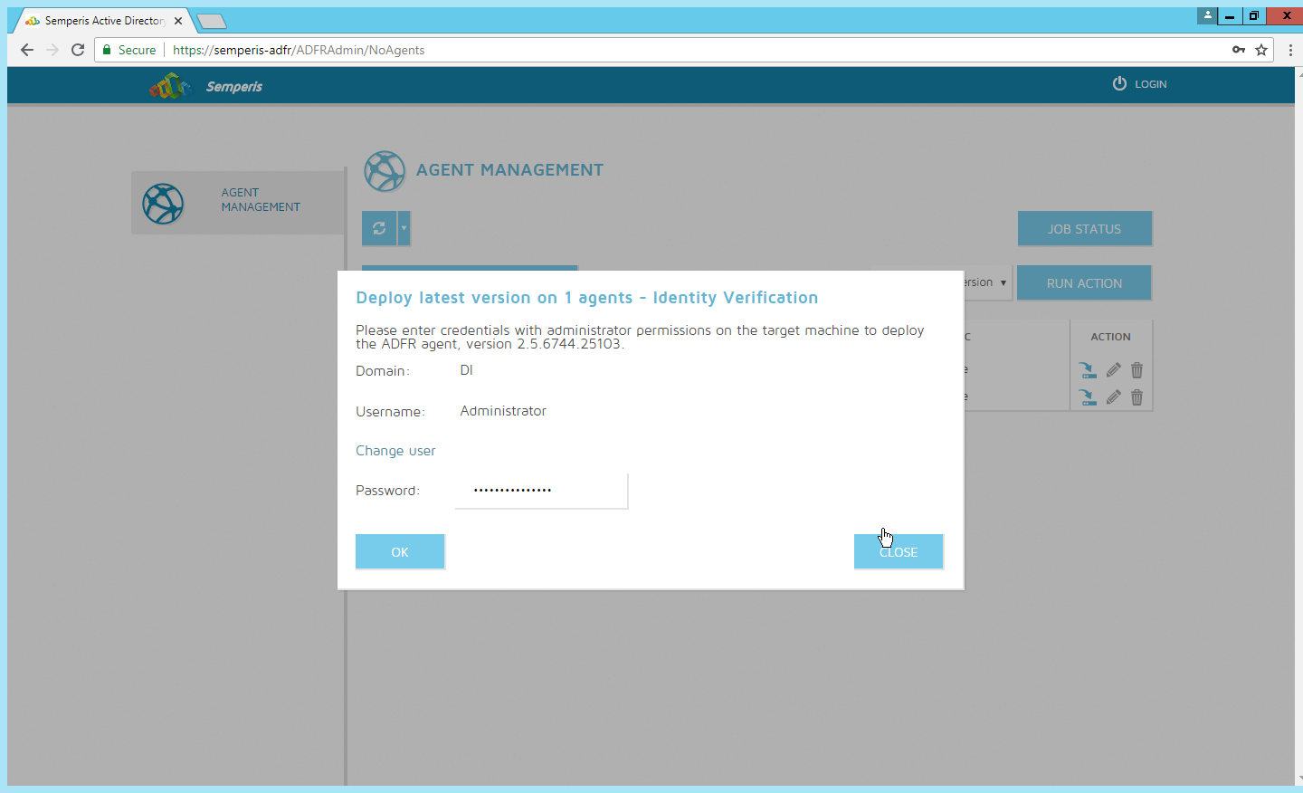
Click OK.
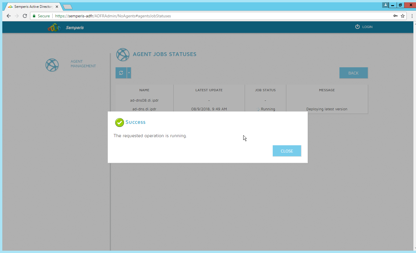
Click Close.
After the installation finishes, click Login at the top of the page.
Enter the login credentials for the domain.
Click Login.
Create a recovery password. (Note: In the event of a restoration, Active Directory will potentially be unavailable, so a separate password that is not domain-associated is needed here for restorations.)
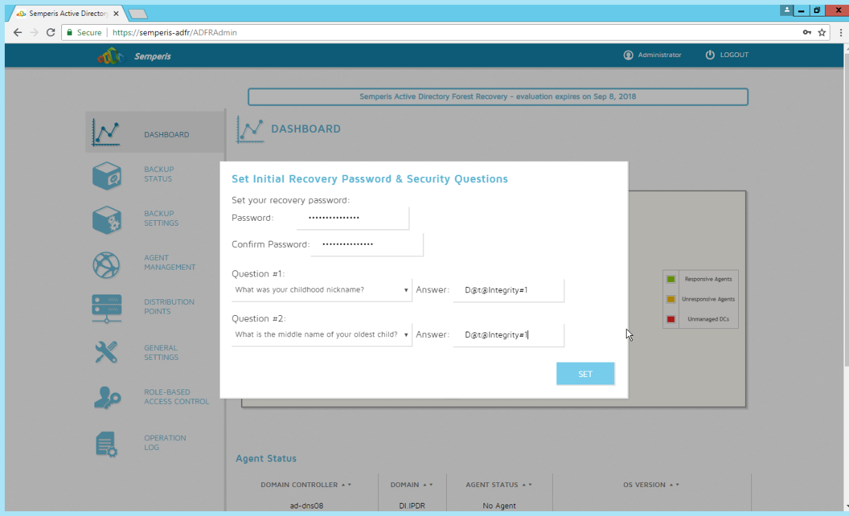
Set recovery questions for the password.
Click Set.
2.9.2 Create a Backup Schedule for the Domain Controller
Click the Backup Settings tab.
Enter a name for the rule.
Select the days and times that the domain controller should be backed up.
Enter the maximum number of backups that should be kept. (Note: The oldest backup will be deleted upon creation of a new backup, which would exceed this maximum.)
Ensure that Encrypt and Rule enabled are both turned on.
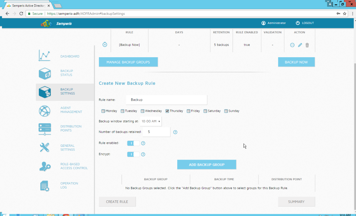
Click Add Backup Group.
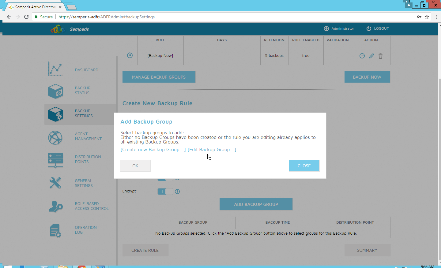
Click Create new Backup Group.
Enter a name for the backup group.
Select the domain controllers to be part of the backup group.
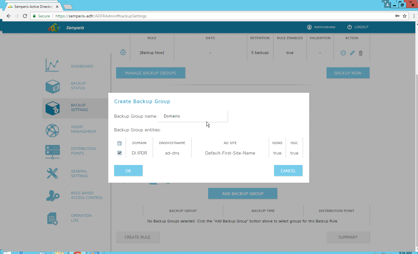
Click OK.
Select the newly created backup group.
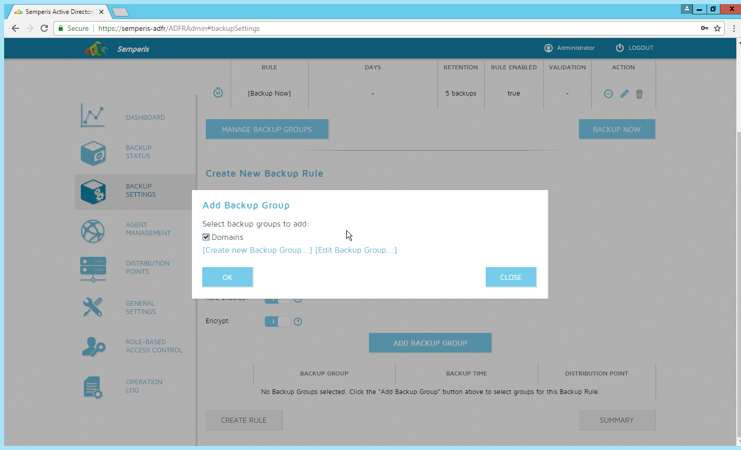
Click OK.
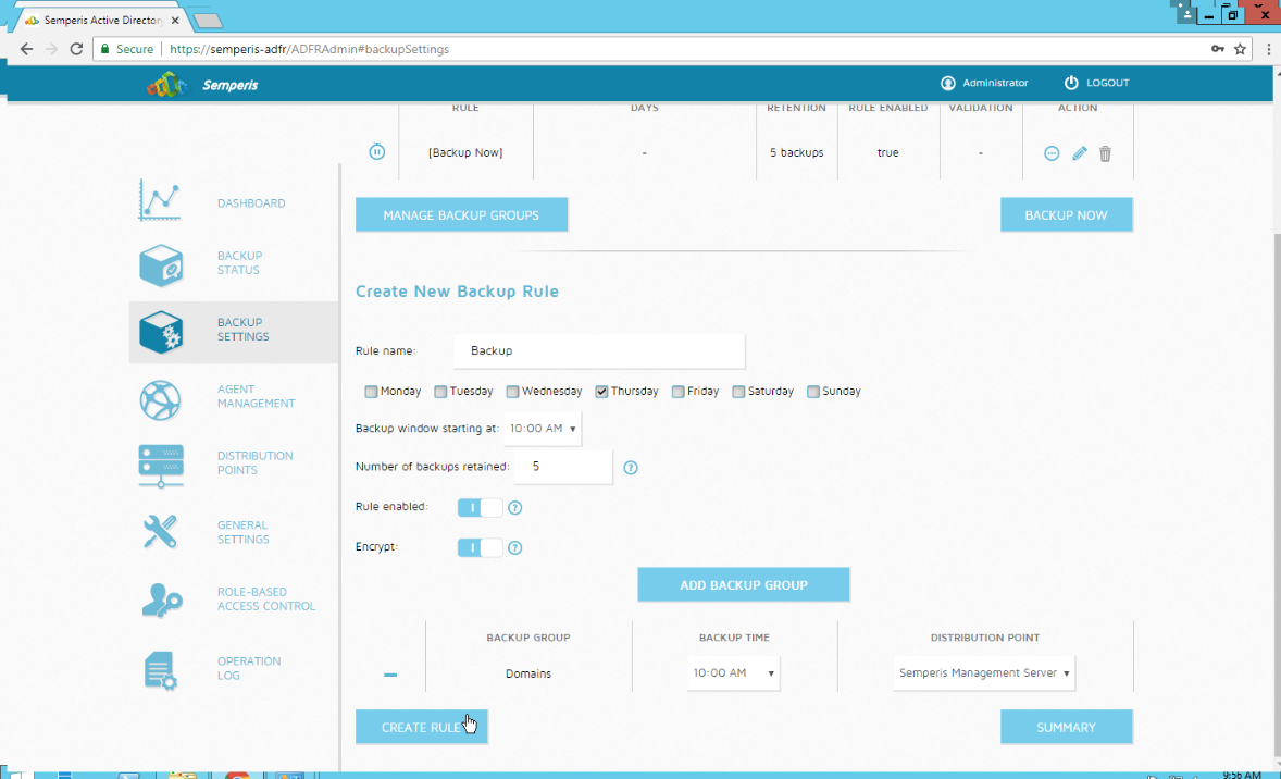
Click Create Rule.
2.9.3 Recover the Active Directory Forest from a Backup
Open the Semperis ADFR web console.
Select Recovery Panel from the drop-down.
Select the Domain that you wish to recover.
Enter the username and password.
Click Login.
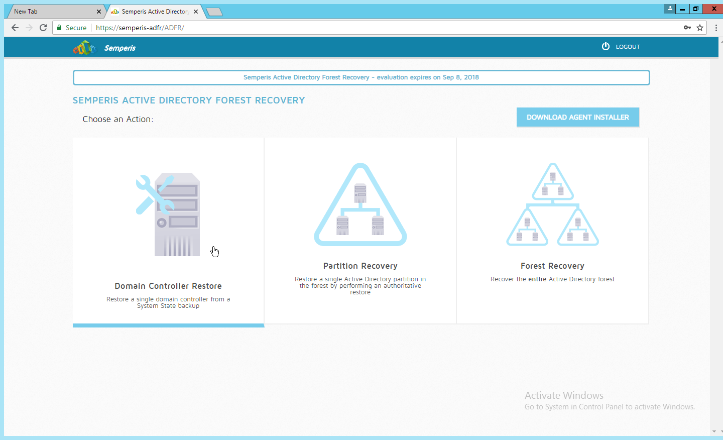
Select an action based on the recovery needs of the organization. In this example we select Domain Controller Restore.
Provide the information for the restoration, namely the domain, the domain controller, and which backup to use.
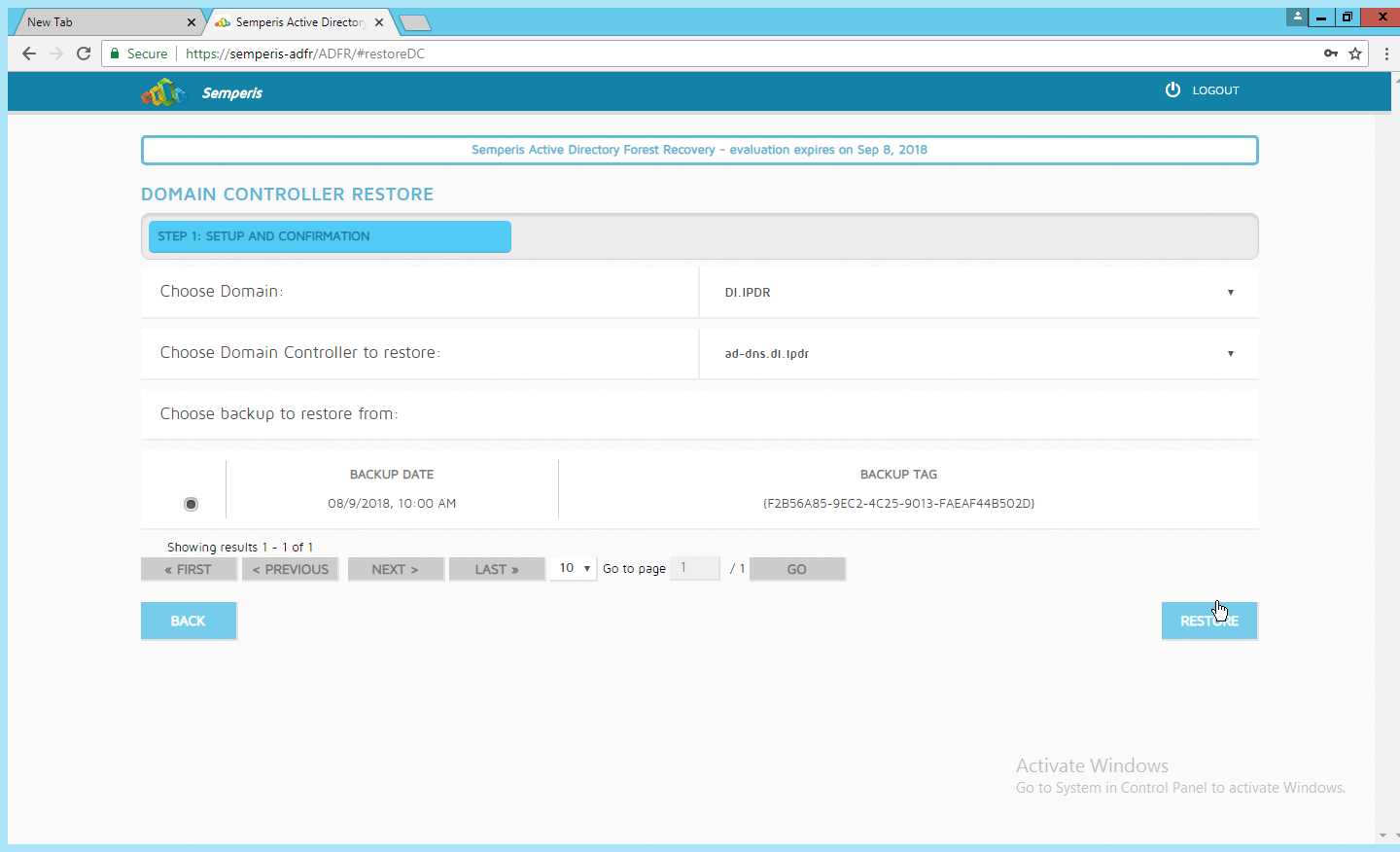
Click Restore.
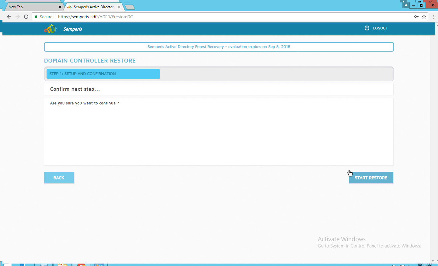
Click Start Restore to begin the restoration process.
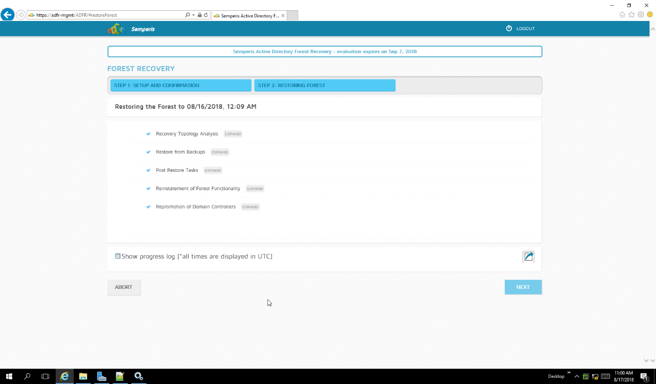
Click Next when the restoration finishes.
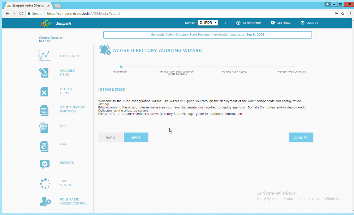
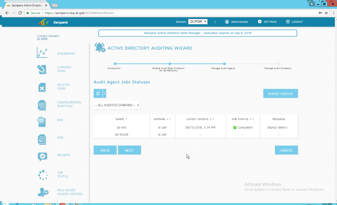
2.10 Semperis Directory Services Protector
This section details the installation of Semperis Directory Services Protector (DSP), a tool used for monitoring Active Directory environments. This installation requires both a copy of SQL Server Express as well as the Semperis Wizard. See the Semperis DS Protector v2.5 Technical Requirements document for specifics on the requirements. For a Windows Server 2012 R2 installation, simply meet the following requirements:
.NET Framework Version 3.5 SP1
.NET Framework Version 4.5.2 or later
joined to the Active Directory domain it is protecting
either the installer for SQL Express Advanced or connection information and credentials for a full version of Microsoft SQL (MSSQL)
2.10.1 Configure Active Directory for Semperis DSP
Open Active Directory Users and Computers.
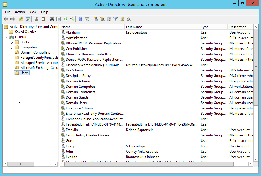
Right-click Users in the left pane and select New > User.
Enter the information for a new user for the DSP service.
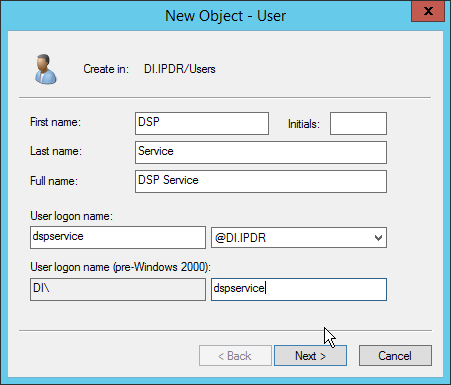
Click Next.
Enter a password twice for this user.
Set the password policy.
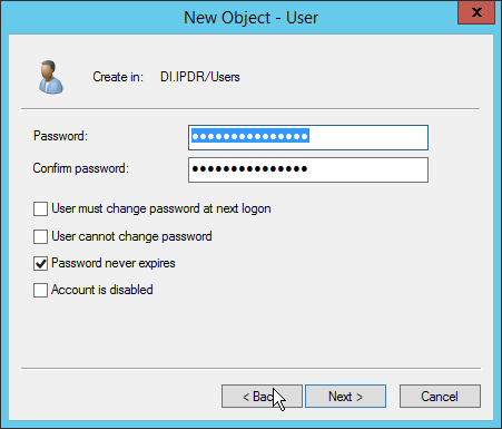
Click Next.
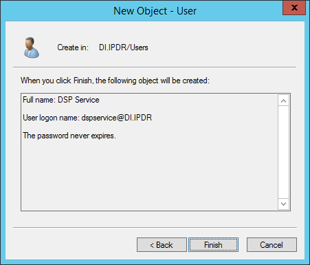
Click Finish.
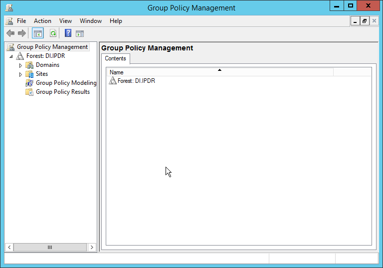
Open Group Policy Management.
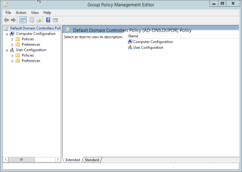
Right-click Domains > DI.IPDR > Domain Controllers > Default Domain Controllers Policy and click Edit.
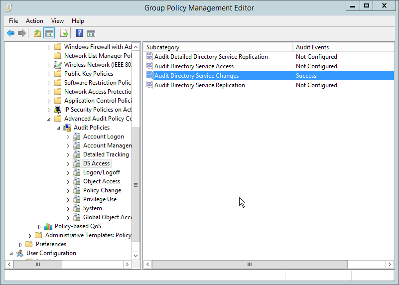
Navigate to Computer Configuration > Policies > Windows Settings > Security Settings > Advanced Audit Policy Configuration > Audit Policies > Account Management.
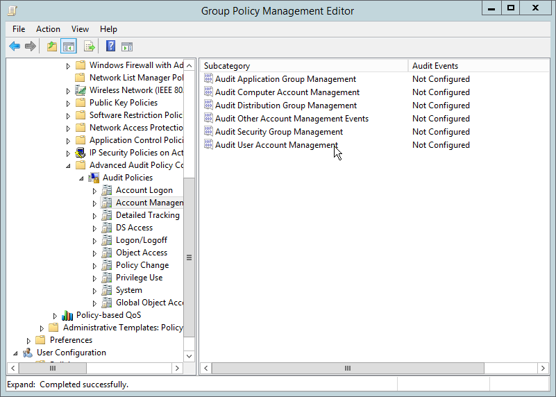
Edit the Audit User Account Management field by double-clicking it.
Check the box next to Configure the following audit events.
Check the box next to Success.
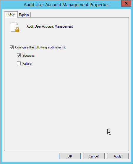
Click OK.
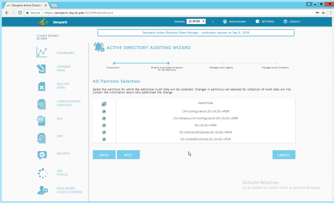
Go to Audit Policies > DS Access.
Double-click Audit Directory Service Changes.
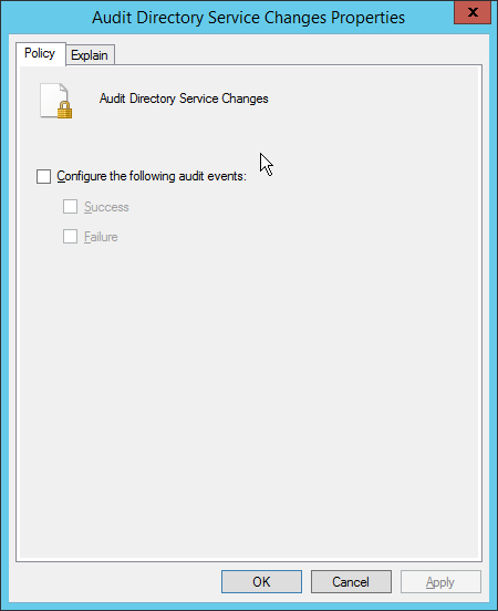
Check the box next to Configure the following audit events.
Check the box next to Success.
Click OK.
Open Active Directory Users and Computers.
Ensure that View > Advanced Features is enabled.
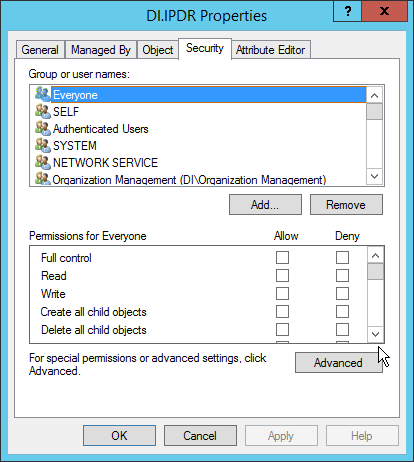
Right-click the domain (for example, DI.IPDR) created earlier and click Properties.
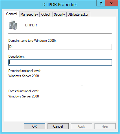
Click the Security tab.
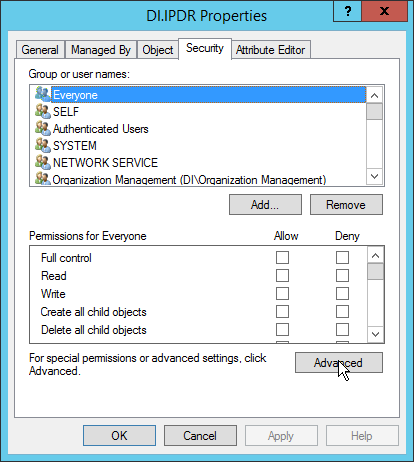
Click Advanced.
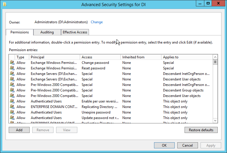
Click the Auditing tab.
Click Add.
Enter Everyone.
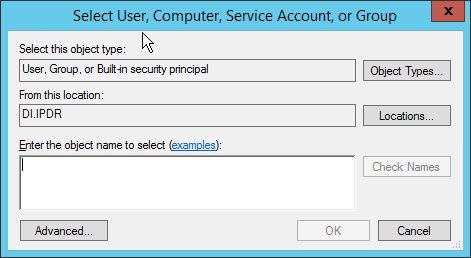
Click OK.
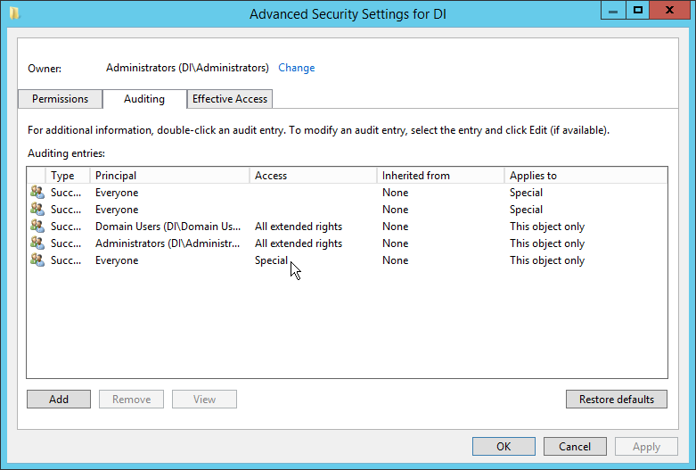
Double-click Everyone.
Check the boxes next to Write all properties, Delete, Delete subtree, Modify permissions, Modify owner, All validated writes, All extended rights, Create all child objects, Delete all child objects.
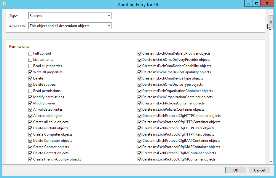
Click OK.
Click OK.
2.10.2 Install Semperis DSP
If you are using a local SQL Express Advanced server, place the SQLEXPRADV_x64_ENU.exe installer in a directory called Setup, and ensure that the Semperis Wizard is adjacent to the Setup folder (not inside it). If an SQL Express Advanced server is not being used, no Setup folder is required.
If prompted to restart the computer, do so.

Click I Agree.
Select Evaluation License.
Select Active Directory State Management.
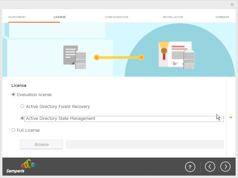
Click the > button.
Enter the username and password of the account created earlier.
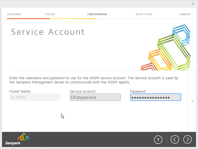
Click the > button.
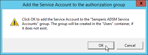
Click OK.
Check the box next to Create the following group.
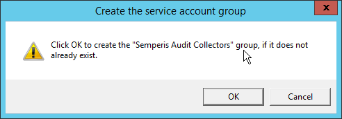
Click OK.
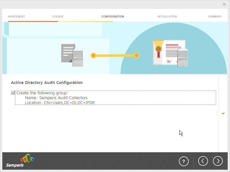
Click the > button.
Select the appropriate database option, and enter any required information.
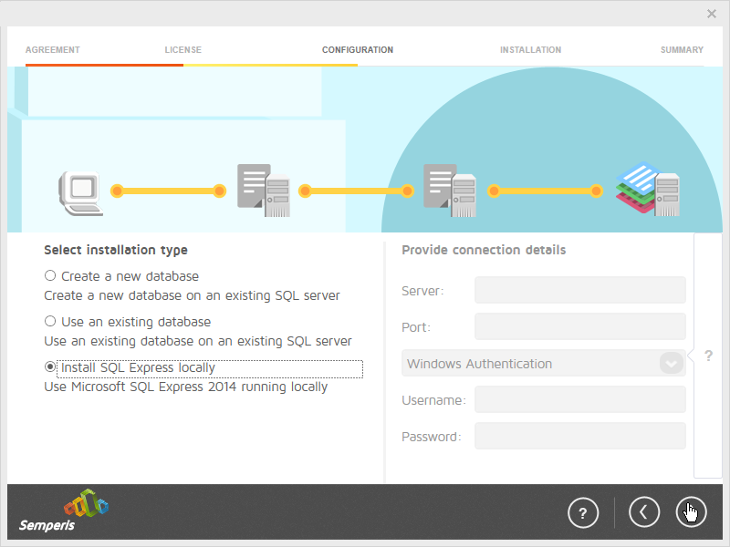
Click the > button.
Click OK.
Click the > button after the installation completes.
There should now be a shortcut on the desktop linking to the web console for Semperis DS Protector.
On the login page, enter the full domain as well as the NetBIOS name.
Enter the username and password of an administrator on the domain.
Click Login.
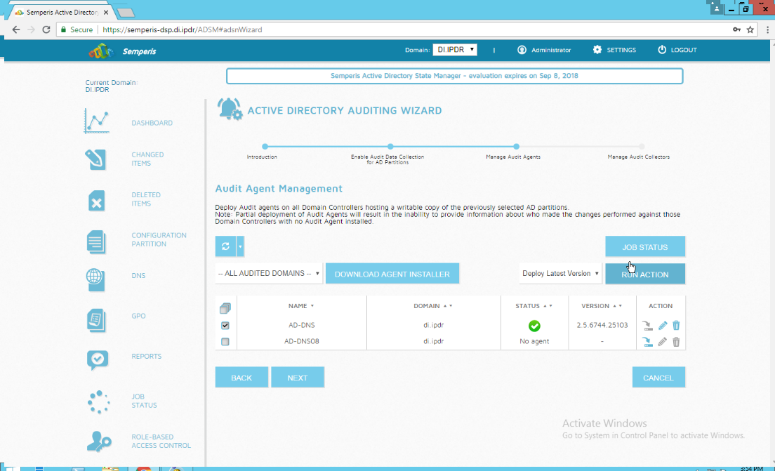
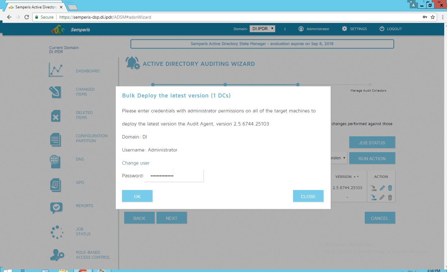
Check the box next to the domain controllers that should be monitored by DSP.
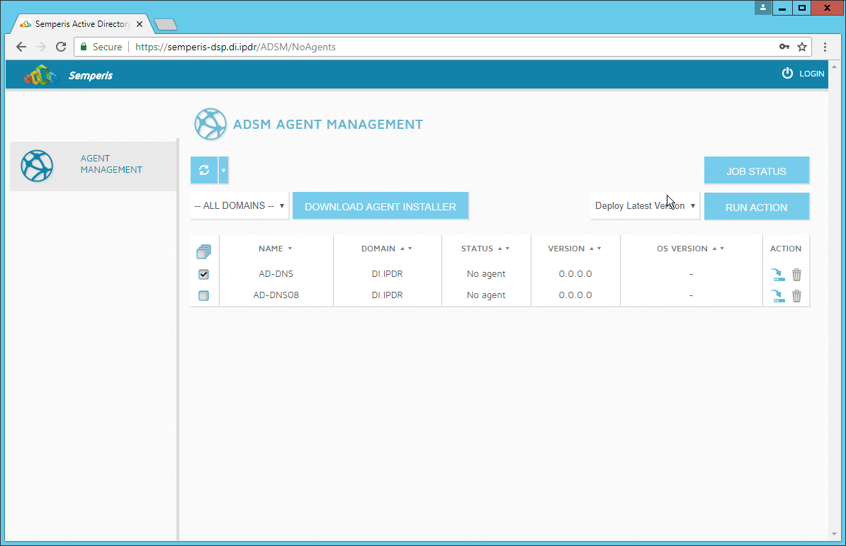
Click Run Action.
Enter the password for the account.
Click OK.
Click Close.
After the agent finishes deploying, click Login at the top of the page and log in.
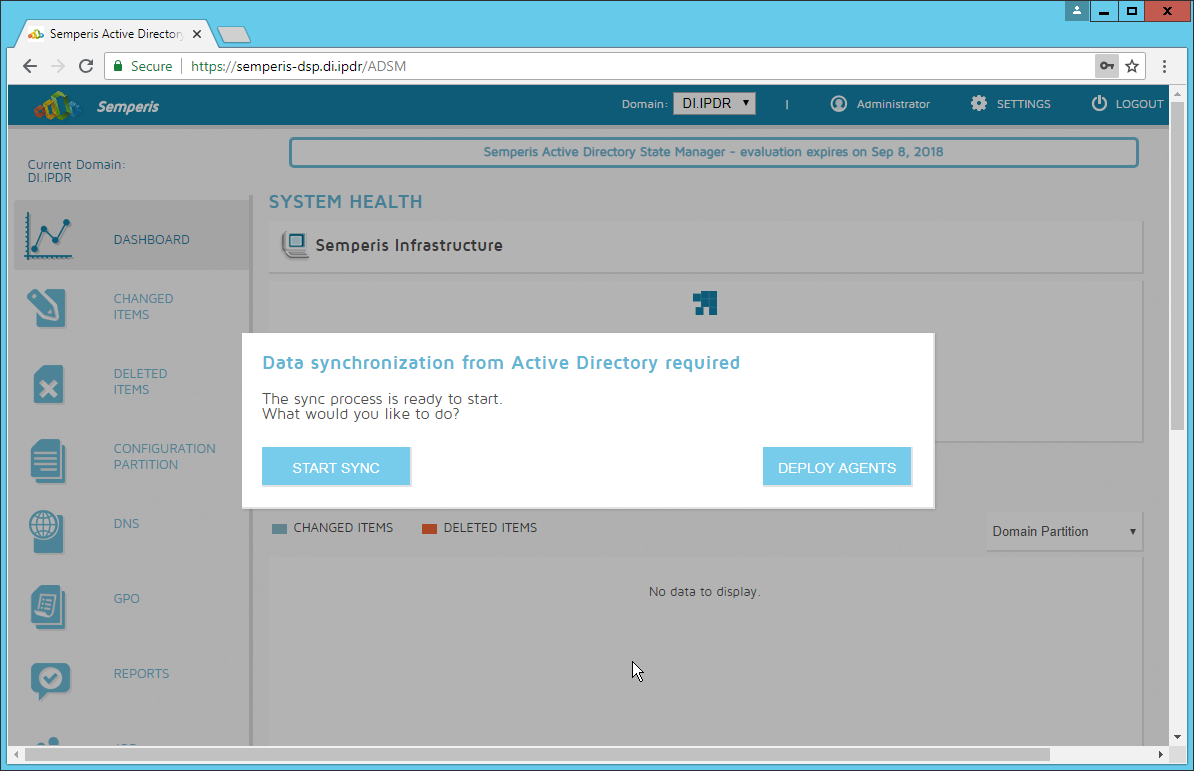
Click Start Sync.
After this completes, click Settings at the top of the page.
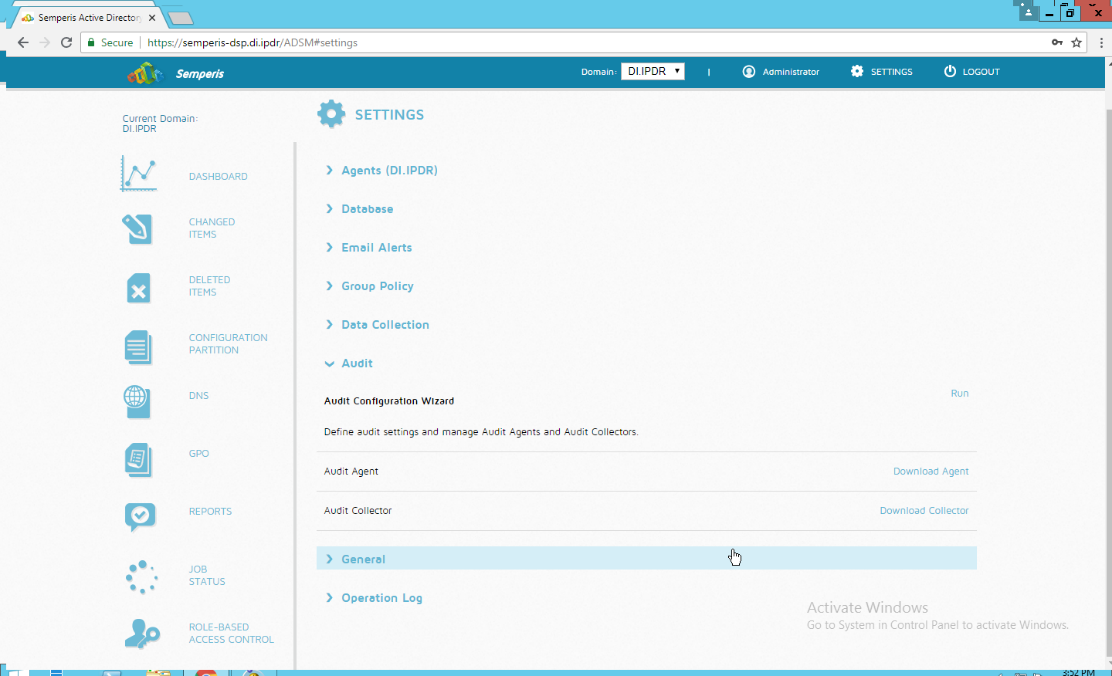
Click Audit.
Click Run.
Click Next.
Click Next.
Check the boxes next to any Domain Controllers that should be monitored.
Click Run Action.
Enter the password.
Click OK.
Wait for the deployment to finish.
Click Next.
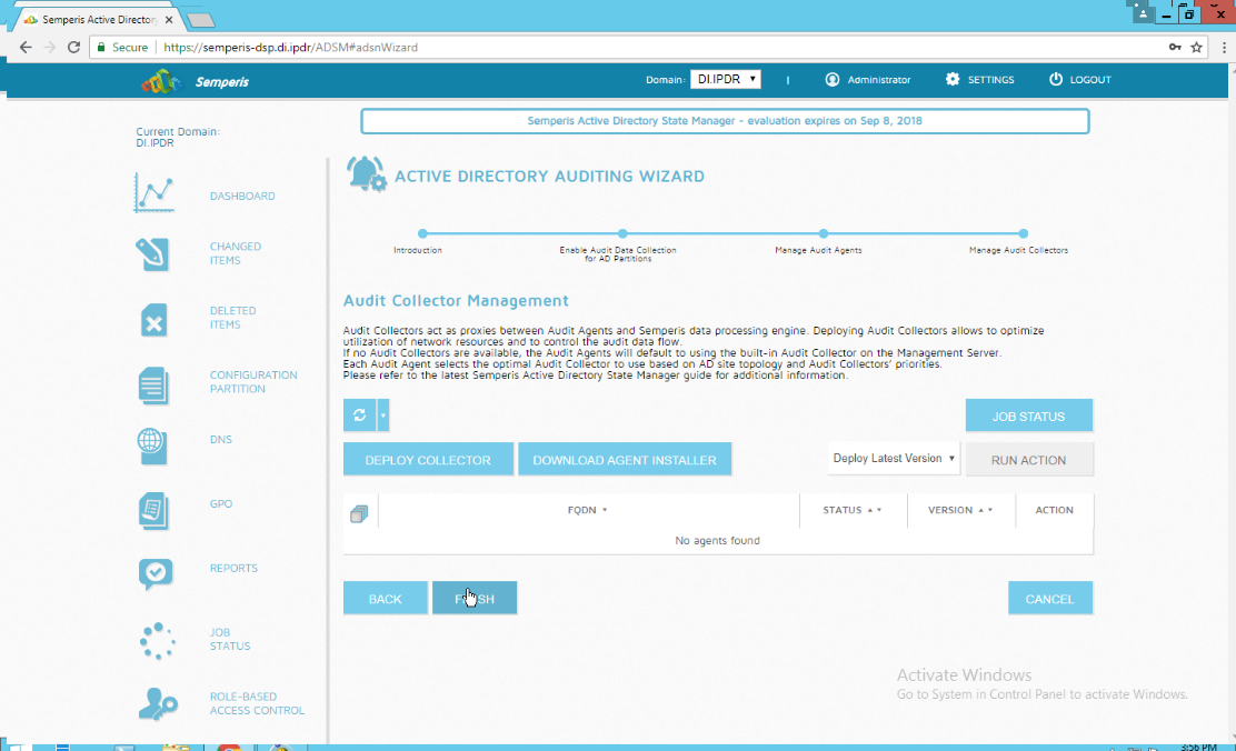
Click Finish.
2.11 Micro Focus ArcSight Enterprise Security Manager
Micro Focus ArcSight Enterprise Security Manager is primarily a log collection/analysis tool with features for sorting, filtering, correlating, and reporting information from logs. It is adaptable to logs generated by various systems, applications, and security solutions.
This installation guide assumes a preconfigured CentOS 7 machine with Enterprise Security Manager (ESM) already installed and licensed. This section covers the installation and configuration process used to set up ArcSight agents on various machines, as well as some analysis and reporting capabilities.
Installation instructions are included for both Windows and UNIX machines, as well as for collecting from multiple machines. Furthermore, integrations with other products in the build are included in later sections.
2.11.1 Install the ArcSight Console
Run ArcSight-7.0.0.2436.1-Console-Win.exe.
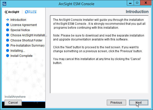
Click Next.
Check the box next to I accept the License Agreement.
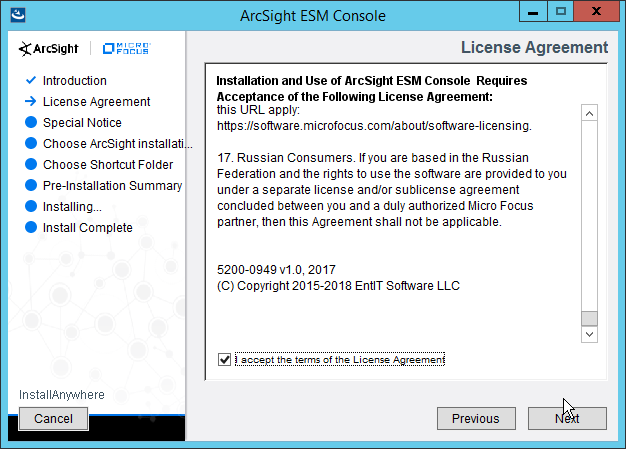
Click Next.
Click Next.
Click Next.

Click Next.
Click Install.
Select No, I do not want to transfer the settings.
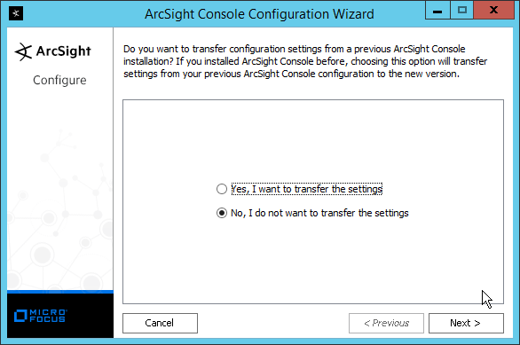
Click Next.
Select Run console in default mode. (This can be changed later according to your organization’s compliance requirements.)
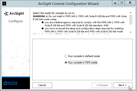
Click Next.
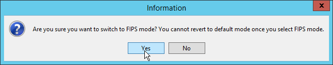
Click Yes.
Select FIPS 140-2.
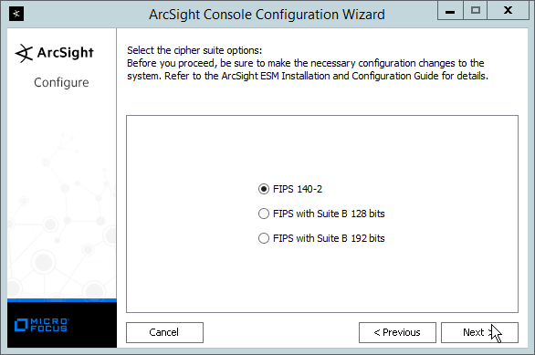
Click Next.
Enter the hostname of the ESM server for Manager Host Name.
Enter the port that ESM is running on for Manager Port (default: 8443).
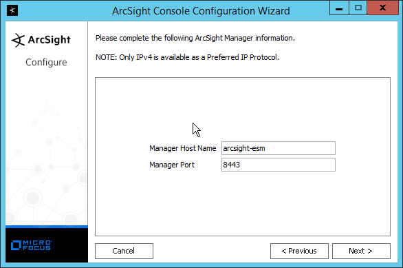
Click Next.
Select Use direct connection.
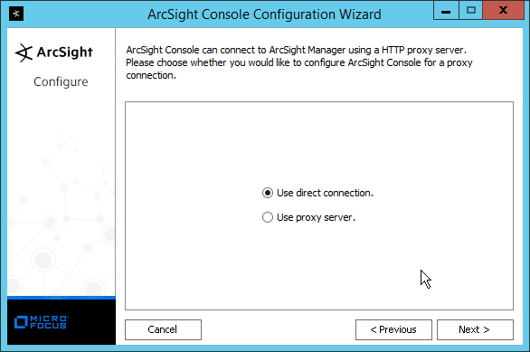
Click Next.
Click Next.
Select your preferred browser.
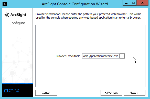
Click Next.
Click Next.
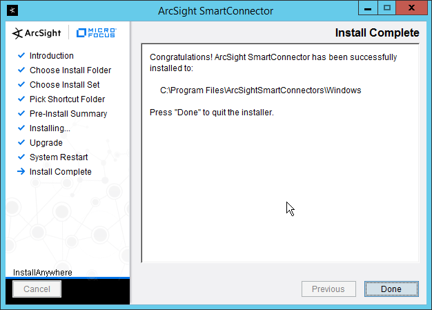
Click Finish.
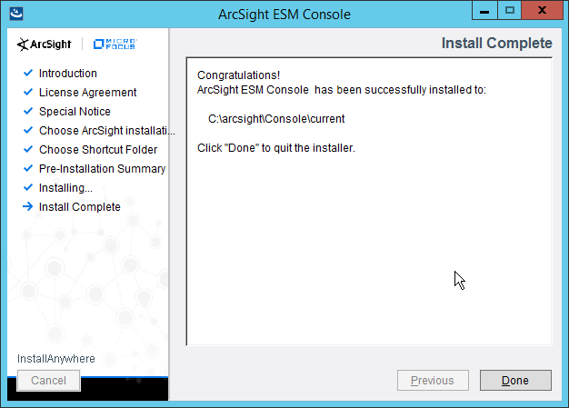
Click Done.
Run ArcSight Console from the Start menu.
Enter the username and password.
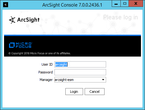
Click Login. (If you are unable to connect, ensure that the hostname of the ESM server is present in your DNS server.)
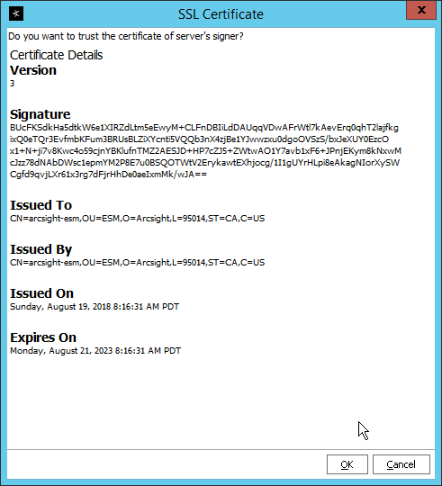
Click OK.
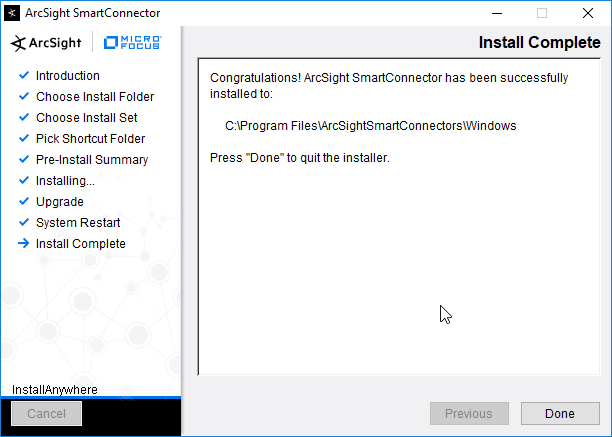
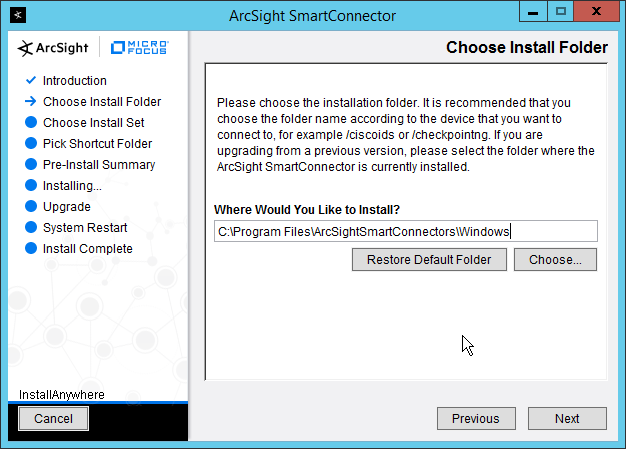
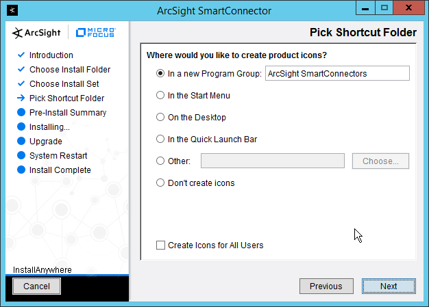
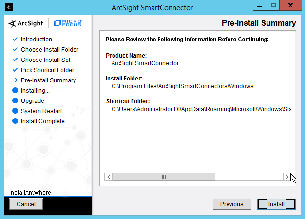
2.11.2 Install Individual ArcSight Windows Connectors
Run ArcSight-7.9.0.8084.0-Connector-Win64.exe.
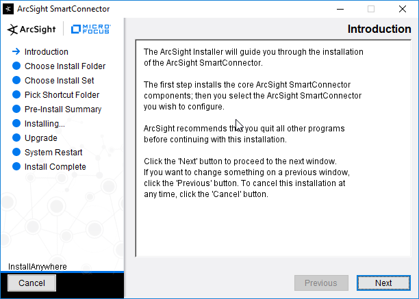
Click Next.
Enter C:\Program Files\ArcSightSmartConnectors\Windows.
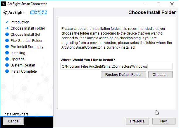
Click Next.
Click Next.
Click Install.
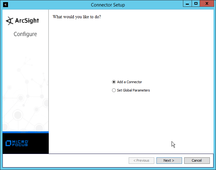
Select Add a Connector.
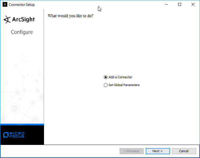
Click Next.
Select Microsoft Windows Event Log–Native.
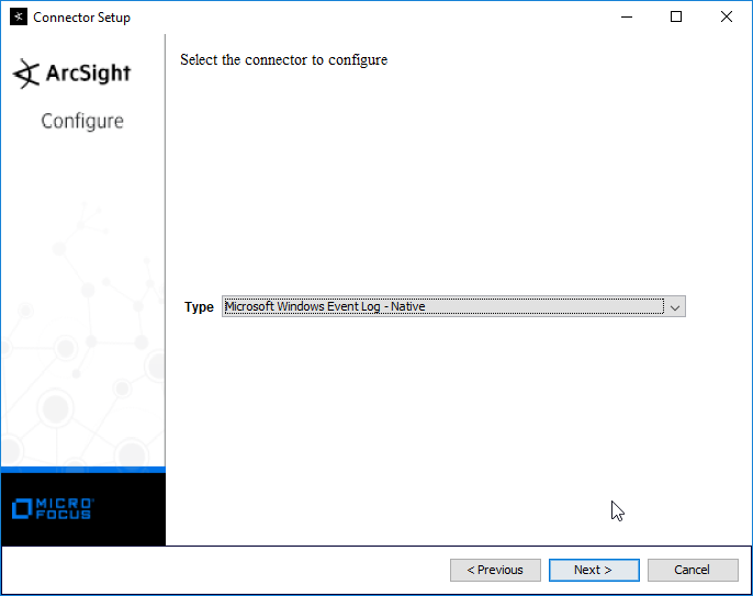
Click Next.
Click Next.

Click Next.
Select ArcSight Manager (encrypted).
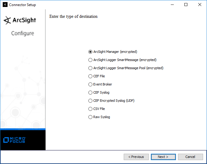
Click Next.
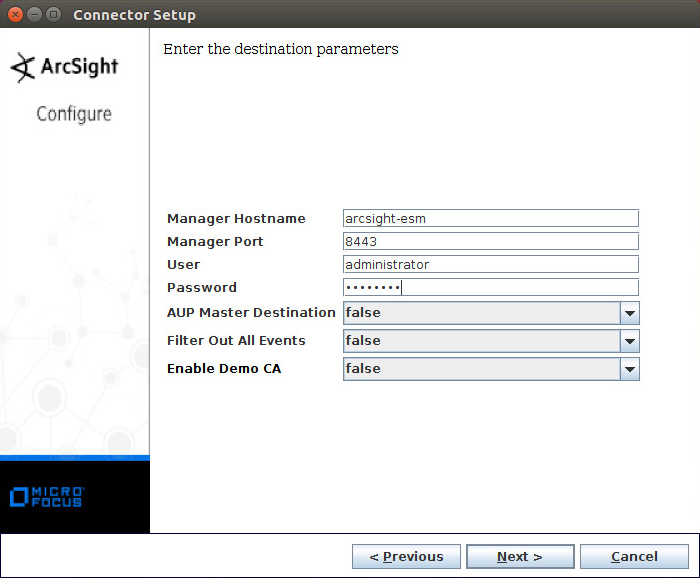
Enter the hostname, port, username, and password for the ArcSight ESM server.

Click Next.
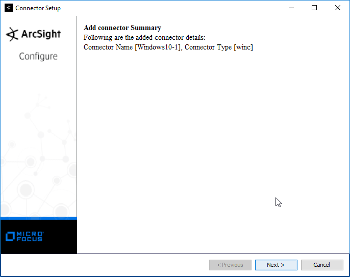
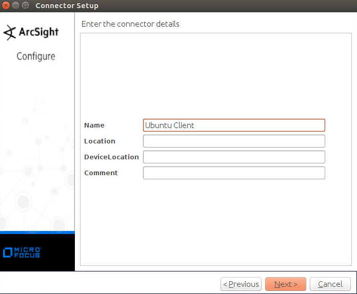
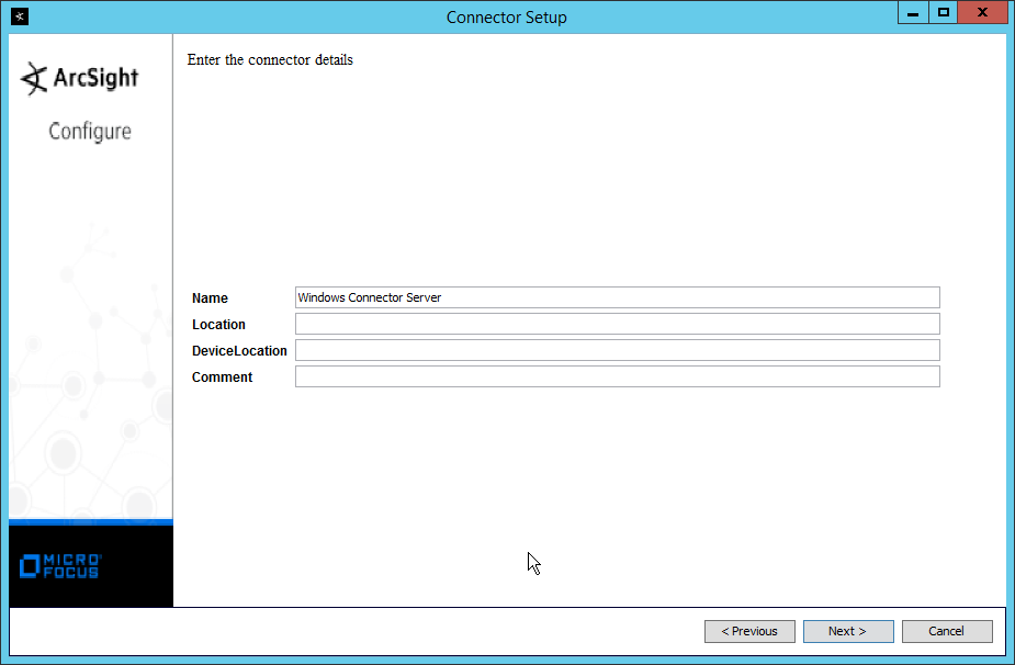
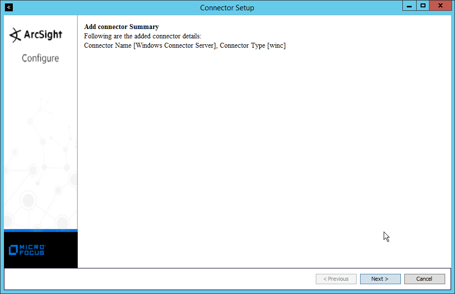
Enter identifying details about the system (only Name is required).

Click Next.
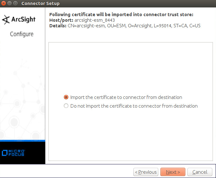
Select Import the certificate to connector from destination.
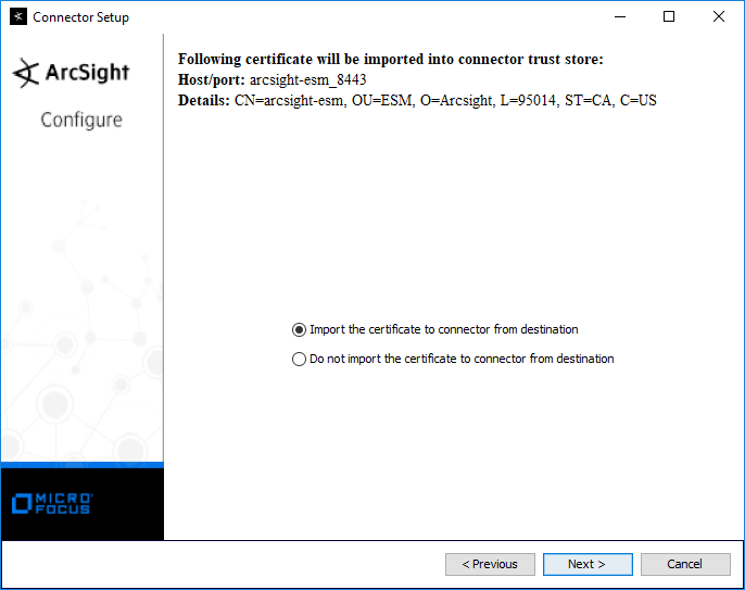
Click Next.
Click Next.
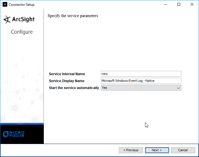
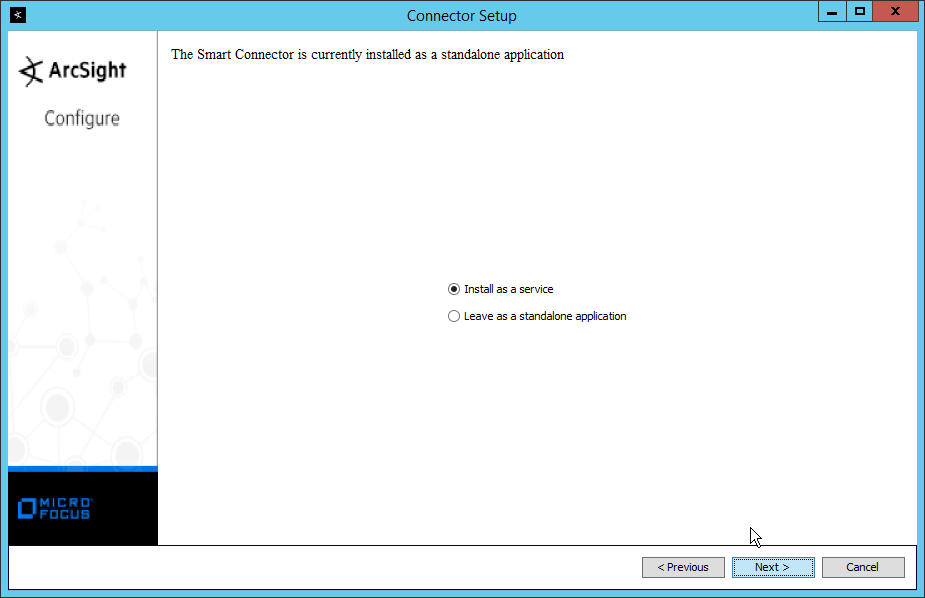
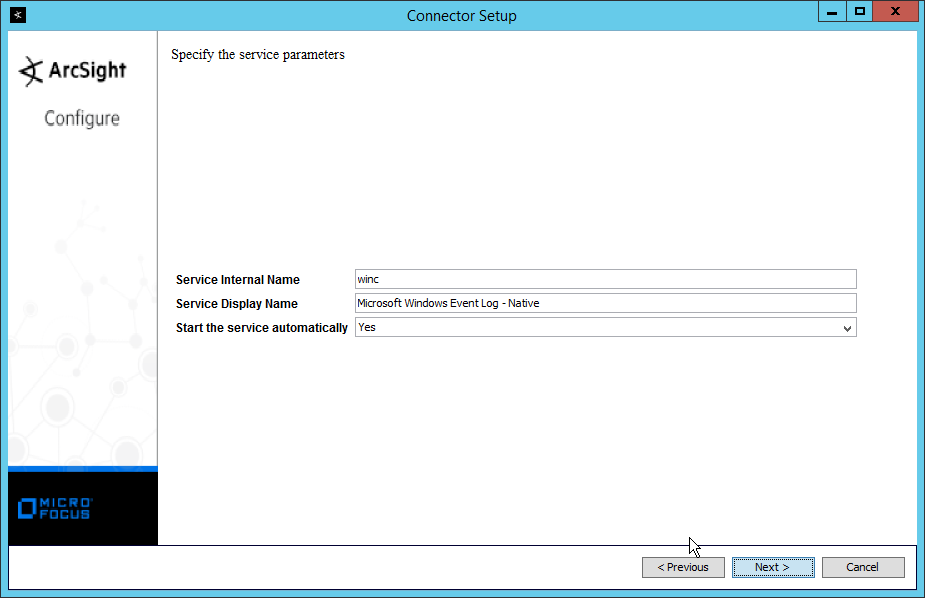
Select Install as a service.
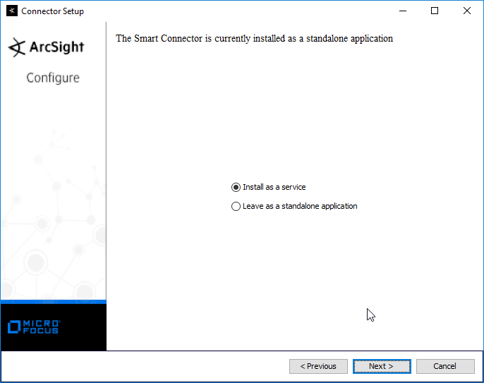
Click Next.
Click Next.
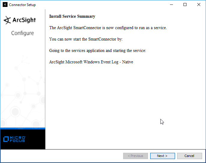
Click Next.
Select Exit.

Click Next.
Click Done.
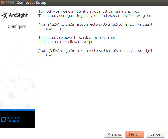
2.11.3 Install Individual ArcSight Ubuntu Connectors
From the command line, run:
> sudo ./ArcSight-7.9.0.8084.0-Connector-Linux64.bin
Enter the password if prompted.
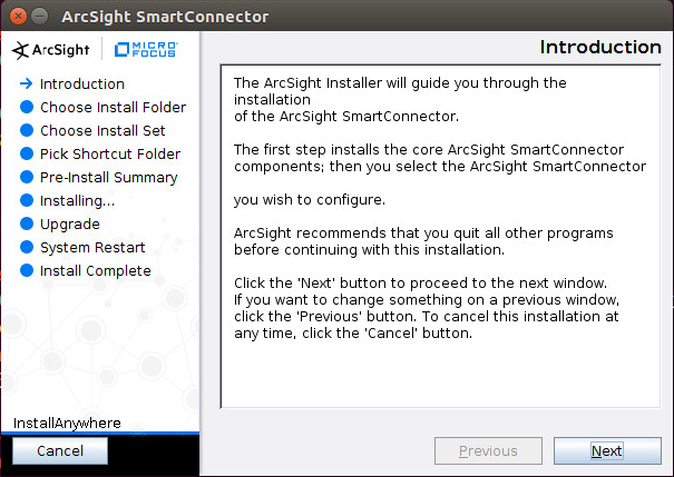
Click Next.
Enter /root/ArcSightSmartConnectors/Ubuntu.
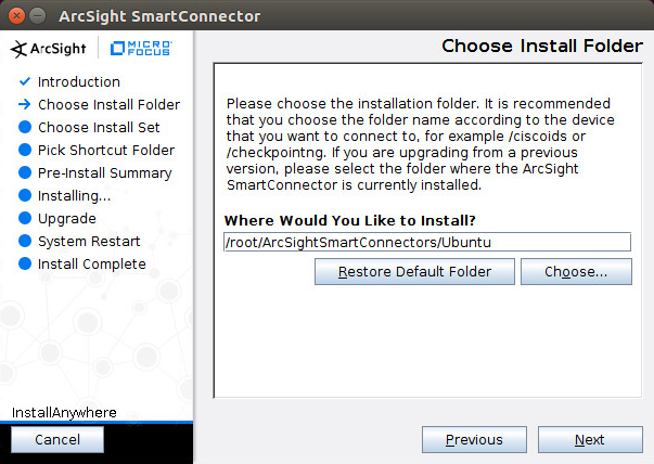
Click Next.
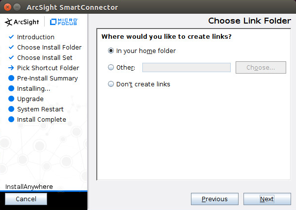
Click Next.
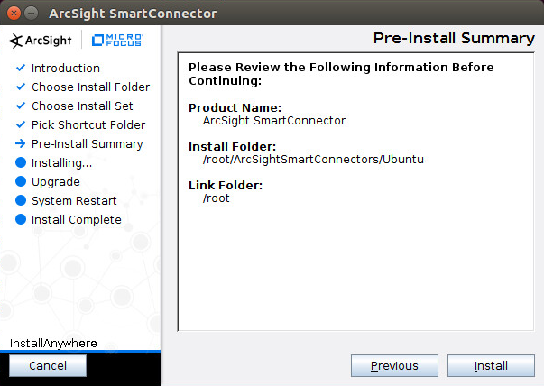
Click Install.
Select Add a Connector.
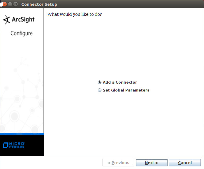
Click Next.
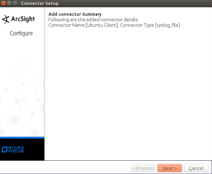
Select Syslog File.
Click Next.
Enter /var/log/syslog for the File Absolute Path Name.
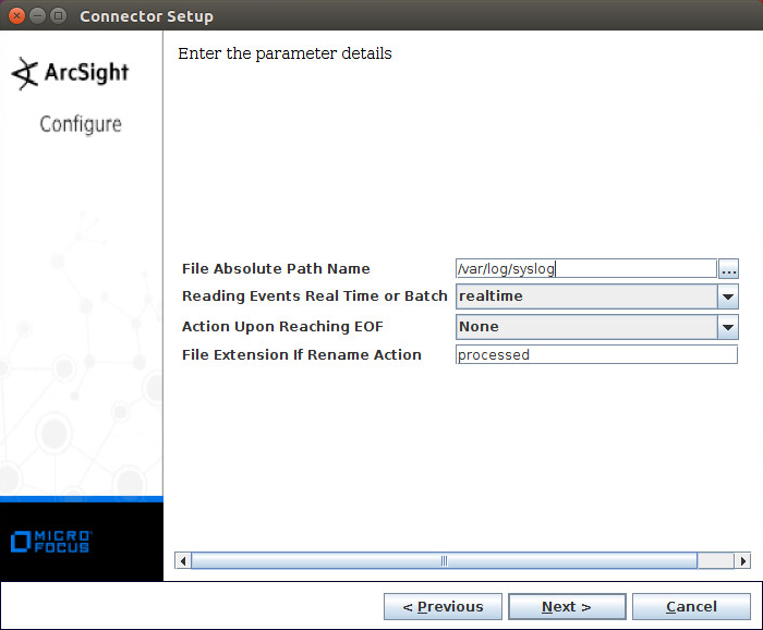
Click Next.
Select ArcSight Manager (encrypted).
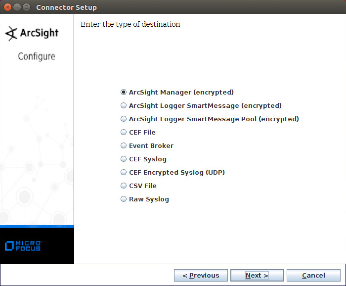
Click Next.
Enter the hostname, port, username, and password for ArcSight ESM.
Click Next.
Enter identifying details about the system (only Name is required).
Click Next.
Select Import the certificate to connector from destination.
Click Next.
Click Next.
Click Next.
Select Exit.
Click Next.
Click Done.
2.11.4 Install a Connector Server for ESM on Windows 2012 R2
Run ArcSight-7.9.0.8084.0-Connector-Win64.exe.

Click Next.
Enter C:\Program Files\ArcSightSmartConnectors\Windows.
Click Next.
Click Next.
Click Install.
Select Add a Connector.
Click Next.
Select Microsoft Windows Event Log–Native.

Click Next.
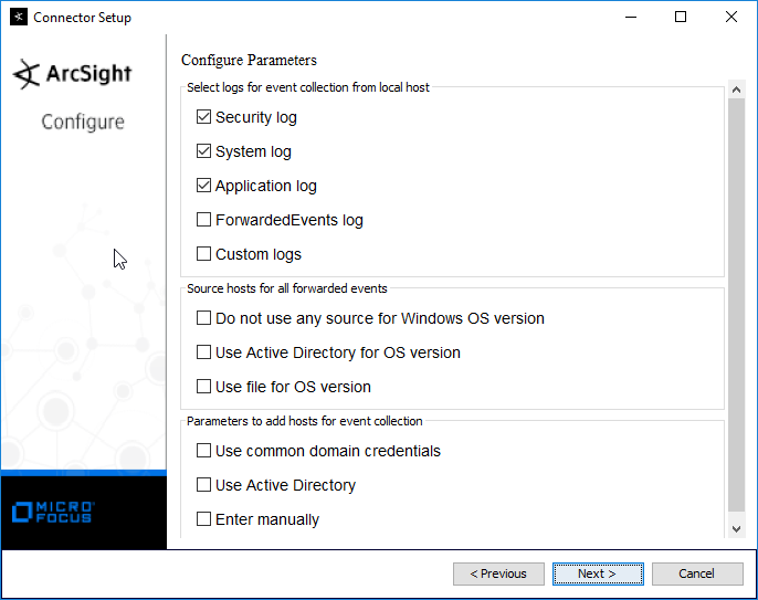
Check the box next to Use Active Directory.
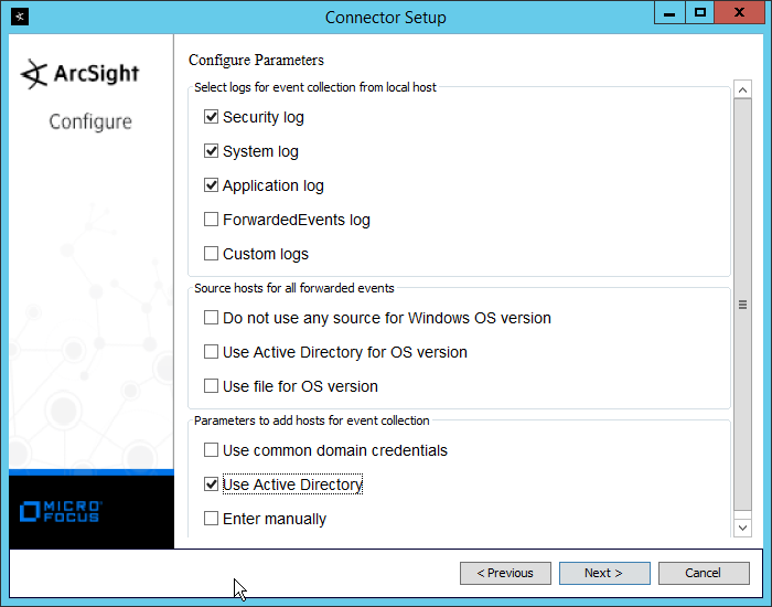
Click Next.
Enter information about your Active Directory server. (It is recommended to create a new administrator account for ArcSight to use.)
Set Use Active Directory host results for to Replace Hosts.
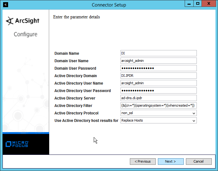
Click Next.
Check the boxes under any event types that should be forwarded to this connector, for each individual host, e.g., Security, System, Application.
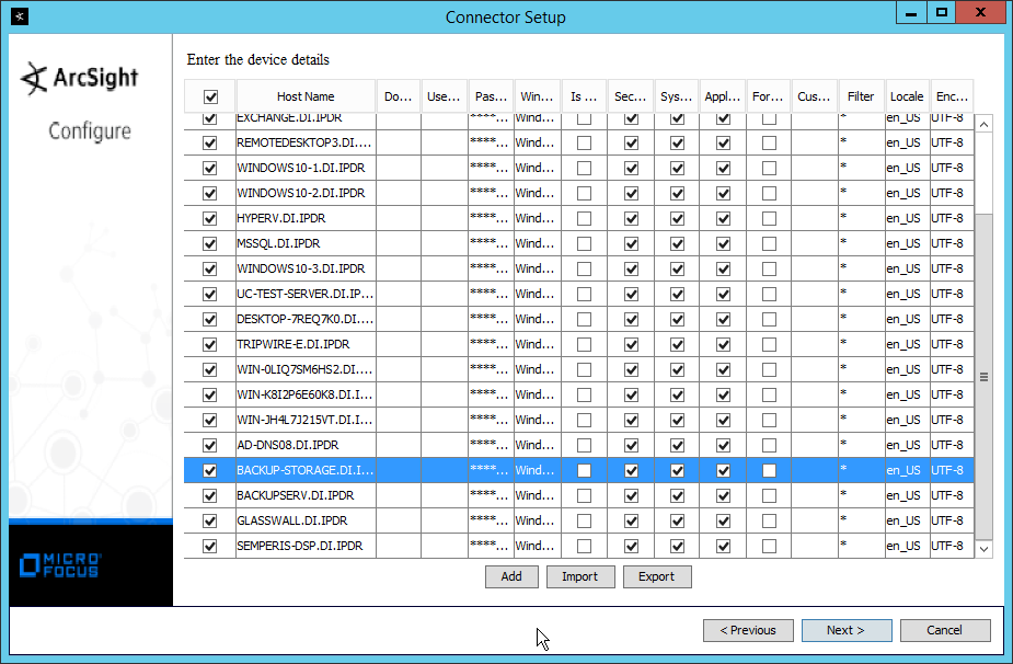
Click Next.

Click Next.
Select ArcSight Manager (encrypted).
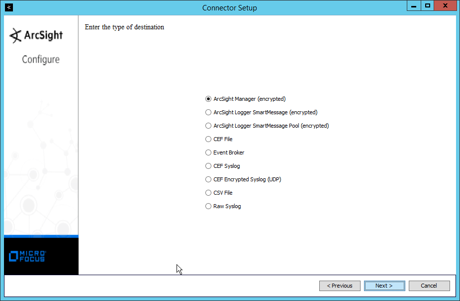
Click Next.
Enter the hostname, port, username, and password for the ArcSight ESM server.
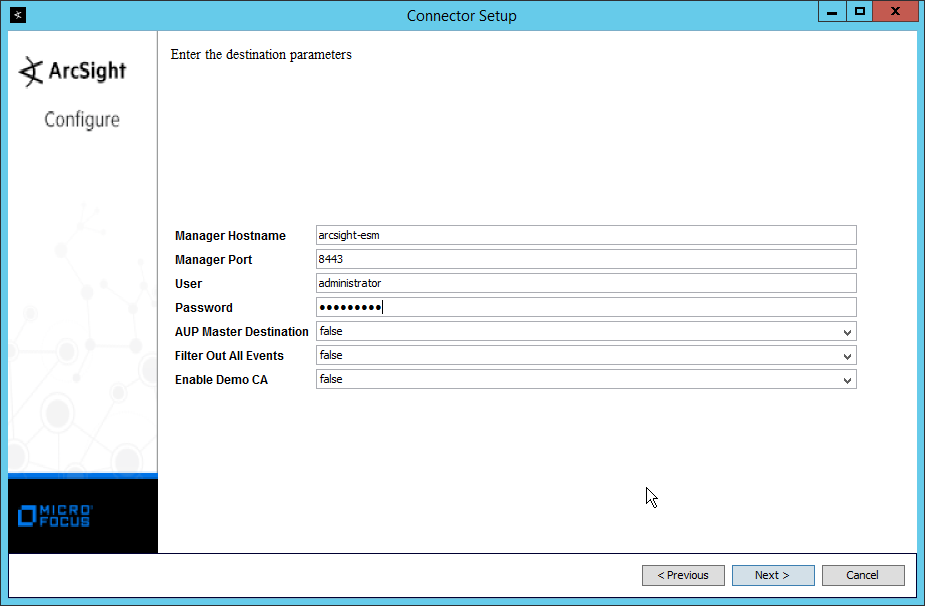
Click Next.
Enter identifying details about the system (only Name is required).
Click Next.
Select Import the certificate to connector from destination.

Click Next.
Click Next.
Select Install as a service.
Click Next.
Click Next.

Click Next.
Select Exit.

Click Next.
Click Done.
Note: Ensure that all machines selected do not block traffic from this device through their firewalls.
2.11.5 Install Preconfigured Filters for ArcSight
2.11.5.1 Install Activate Base
Go to the ArcSight Content Brain web application (https://arcsightcontentbrain.com/app/) and log in. This page allows you to keep track of packages to be installed–what packages should be installed depends on the needs of the organization, but the “Activate Base” is required for all products.
Click the Download link for the Activate Base. (Note: This package should be installed on the ArcSight Console, not on the ESM.)
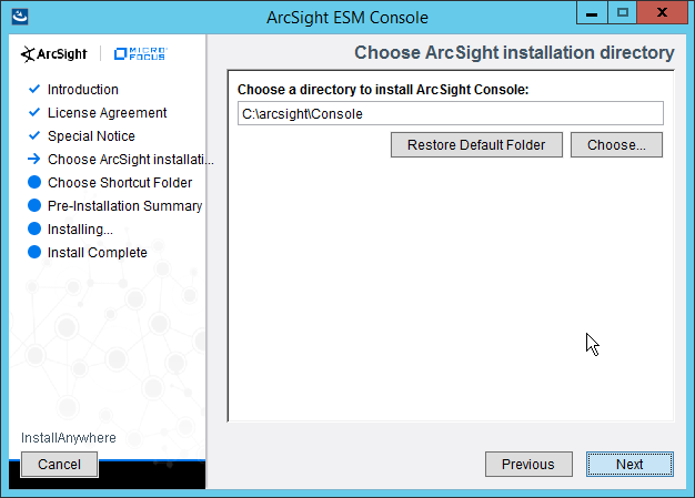
Copy the contents of the zip file to ARCSIGHT_HOME. The default for this is C:\arcsight\Console\current, assuming a Windows Server.
- In PowerShell, navigate to the ARCSIGHT_HOME directory (C:\arcsight\Console\current) and run:
> .\ActivateBaseInstallAndUpdate2540.bat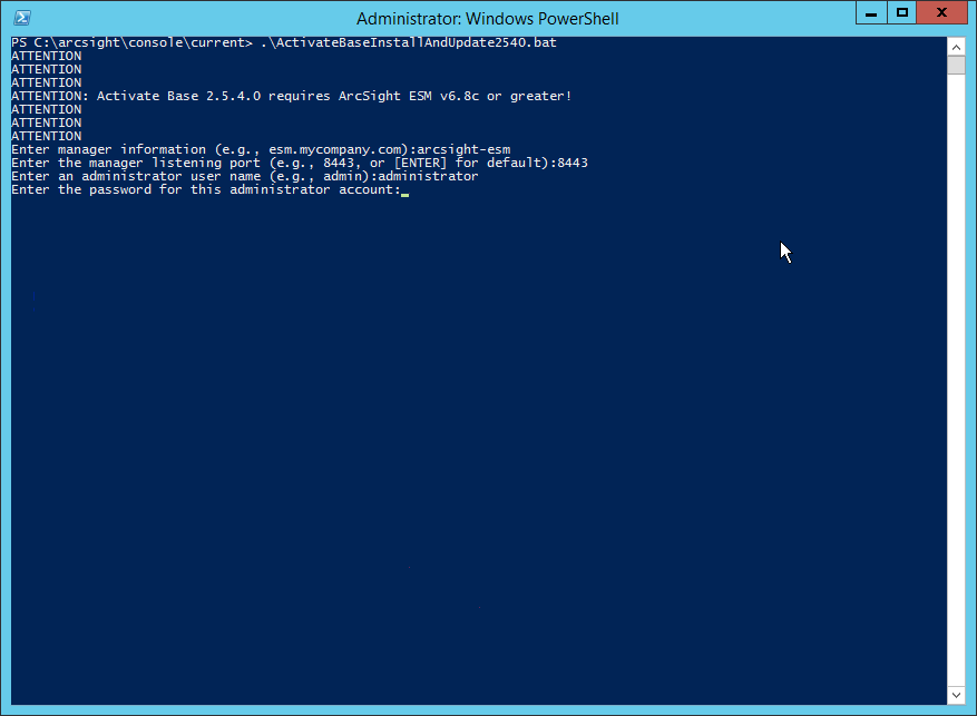
Enter the hostname of the ArcSight machine, the port (default: 8443), and the username and password used to connect to the ESM.
Delete Activate_Base_Updated_2.5.4.0.arb from the ARCSIGHT_HOME directory.
Log in to ArcSight Console.
Under Packages > Shared > All Packages > ArcSight Activate, right-click Activate Base Update 2.5.4.0, and select Delete Package.
2.11.5.2 Install Packages
Once the Activate Base is installed, packages can be installed to monitor for specific types of events. As an example, find below instructions for the Malware Monitoring package.
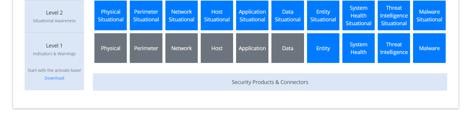
Navigate to the ArcSight Content Brain web application.
Select the Level 1 box labeled Malware.
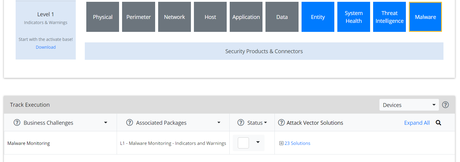
In the Track Execution section, under Associated Packages, you can see the list of packages used to address the challenge of Malware Monitoring. In this case, there is just one package, L1– Malware Monitoring–Indicators and Warnings. Click the link to be taken to a download page for the package, and download it. (Note: This package should be installed on the ArcSight Console, not on the ESM.)
Copy the contents of the zip file to ARCSIGHT_HOME. The default for this is C:\arcsight\Console\current, assuming a Windows Server.
In PowerShell, navigate to the ARCSIGHT_HOME directory (C:\arcsight\Console\current) and run:
> .\L1-Malware_Monitoring_1.1.0.1.bat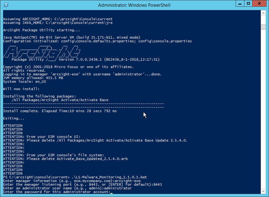
Enter the hostname of the ArcSight machine, the port (default: 8443), and the username and password used to connect to the ESM.
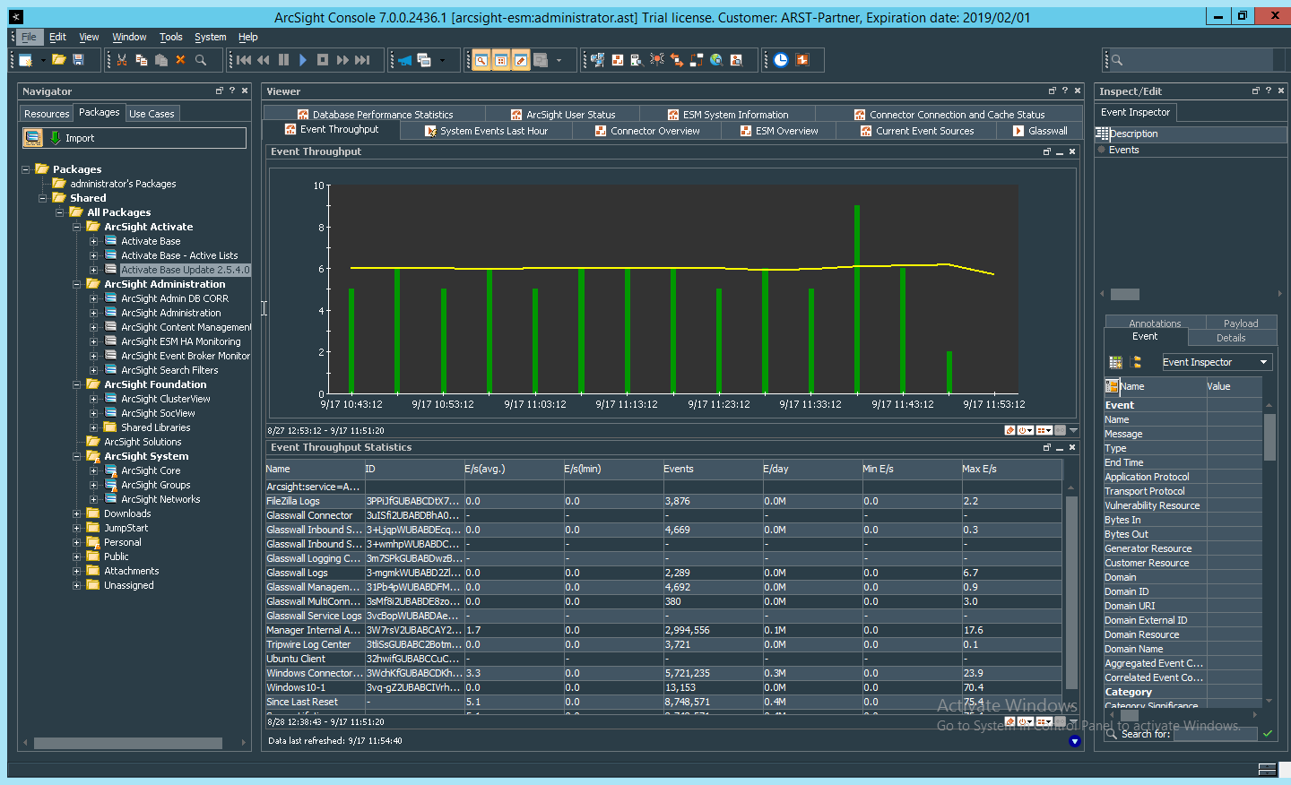
2.11.6 Apply Filters to a Channel
In the ArcSight Console, click File > New > Active Channel.
Enter a name for the channel.
Select a time frame.
For Filter, select one the filters that was imported from the packages you installed.
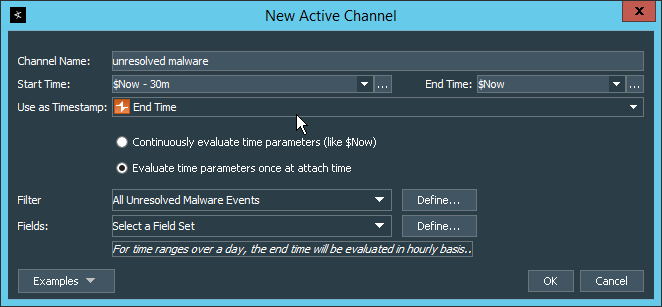
Click OK. All events that match the filter can be displayed in the newly created channel. Filters from imported packages can be found under Filters > Shared > All Filters > ArcSight Activate > Solutions.
2.12 Tripwire Enterprise
Notes:
This installation requires MSSQL to be installed on a remote server and configured according to the instructions in the Tripwire Enterprise 8.6.2 Installation and Maintenance Guide.
2.12.1 Install Tripwire Enterprise
Ensure that you have an up-to-date version of Oracle Java. You must install both the Java Runtime Environment (JRE) and the Java Cryptography Extension (JCE).
Download and run the JRE installer.
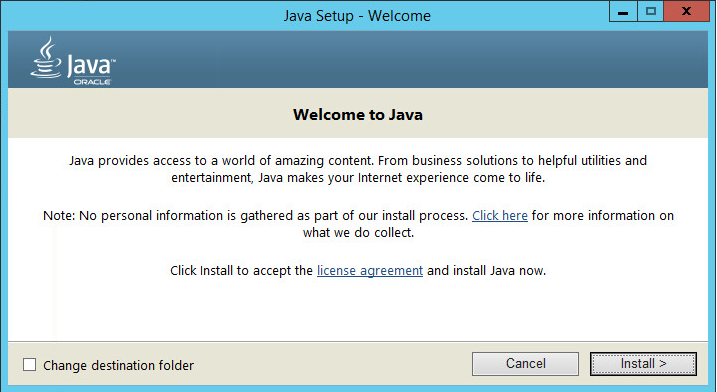
Click Install.
Download the JCE and extract the files.
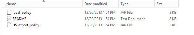
Copy the local_policy.jarand US_export_policy.jar files to /lib/security/Unlimited/ and /lib/security/Limited in the Java installation directory.
Run install-server-windows-amd64.
Select the Java runtime that was just installed.
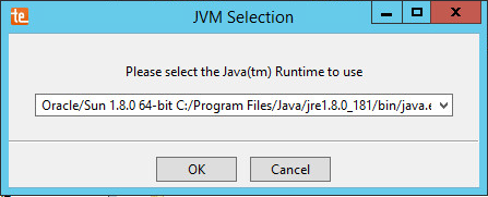
Click OK.
Click Next.
Select I accept the agreement.
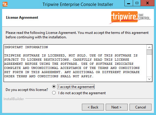
Click Next.
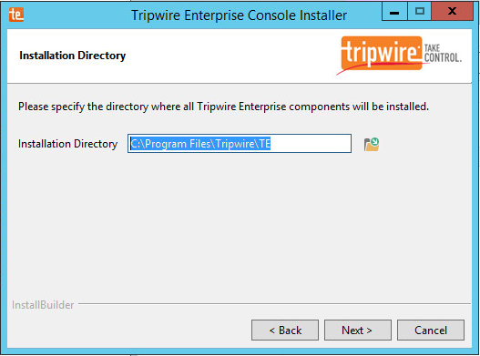
Click Next.
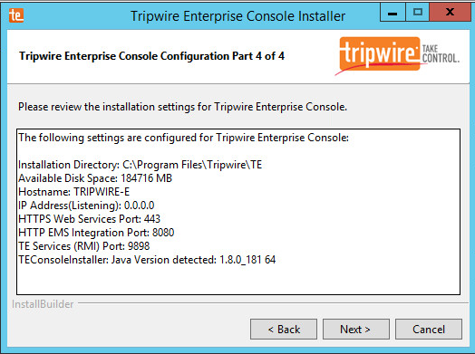
The installer should automatically detect the hostname of the system on which Tripwire Enterprise is being installed. If it does not, enter the hostname here.
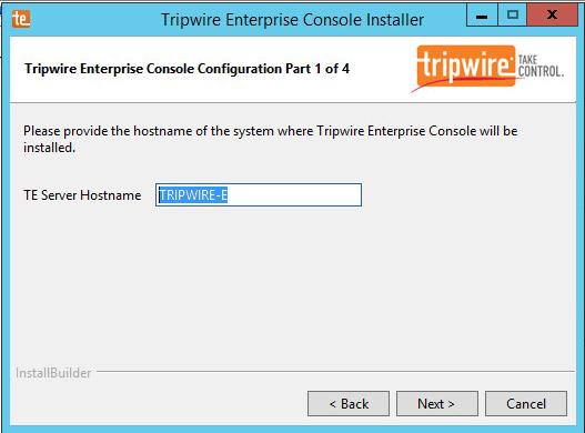
Click Next.
Enter each port number to use for the HTTPS Web Services port, HTTP EMS Integration Port, and Tripwire Enterprise RMI port. The RMI port is used for inbound communication from Tripwire agents to the server, so ensure that it is allowed through the firewall.
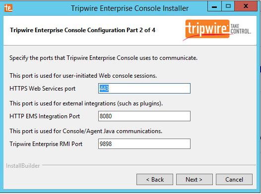
Click Next.
Enter a passphrase to use.
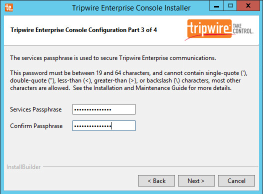
Click Next.
Click Next.
Check the box next to Install Real-time Monitoring.
Enter 1169 for Real-time Port.
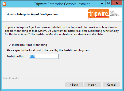
Click Next.
Click Next.
Check the box next to Open a browser after clicking Finish to continue configuring Tripwire Enterprise.
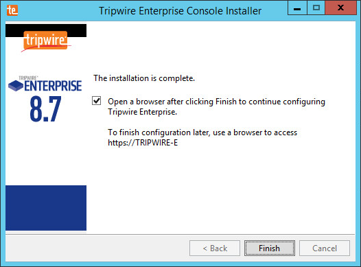
Click Finish.
Once at the web address, enter the Services passphrase chosen earlier.
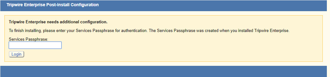
Click Login.
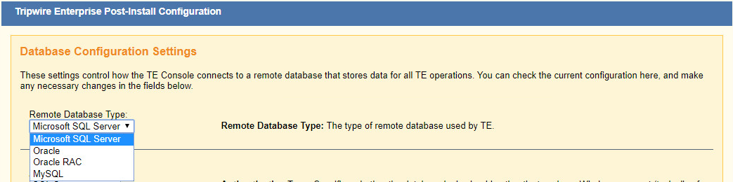
Select Microsoft SQL Server for Remote Database Type.
Select SQL Server for Authentication Type.
Enter login details for the account created during the MSSQL setup.
Enter the hostname or IP of the database server.
Enter the port on which the database is operating.
Enter the name of the database to be used for Tripwire Enterprise.
Select the appropriate setting for SSL according to your organization’s needs.
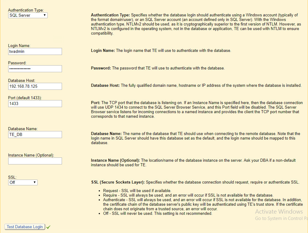
Click Test Database Login to ensure the connection is functional.
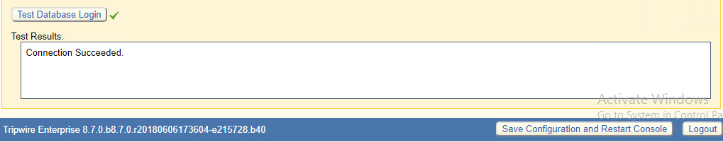
Click Save Configuration and Restart Console.
After the reboot, enter a new administrator password.
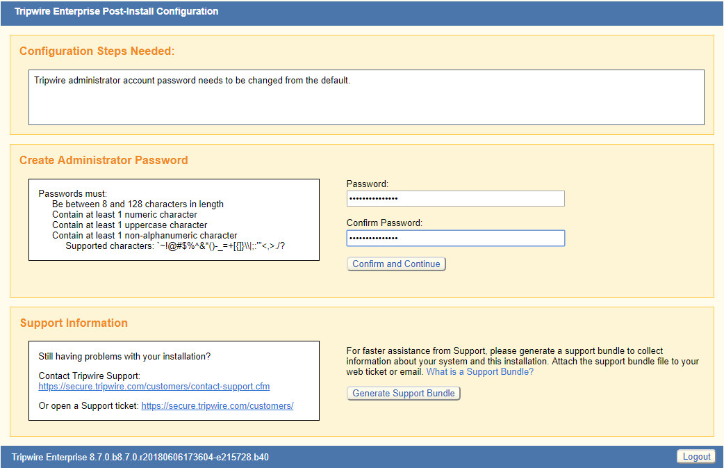
Click Confirm and Continue.
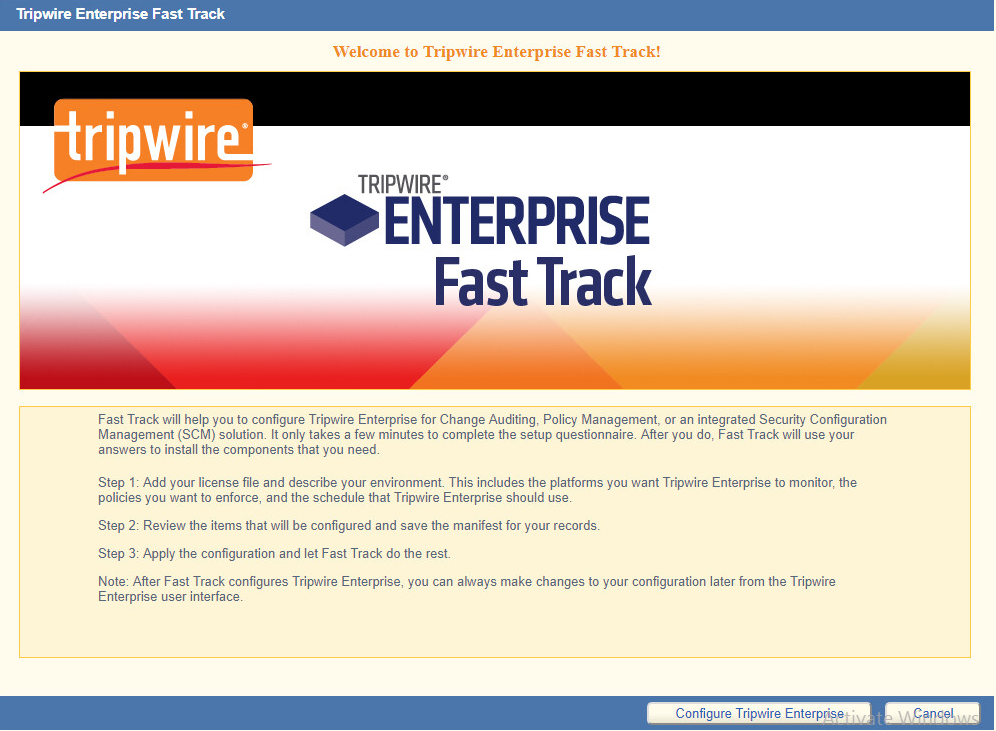
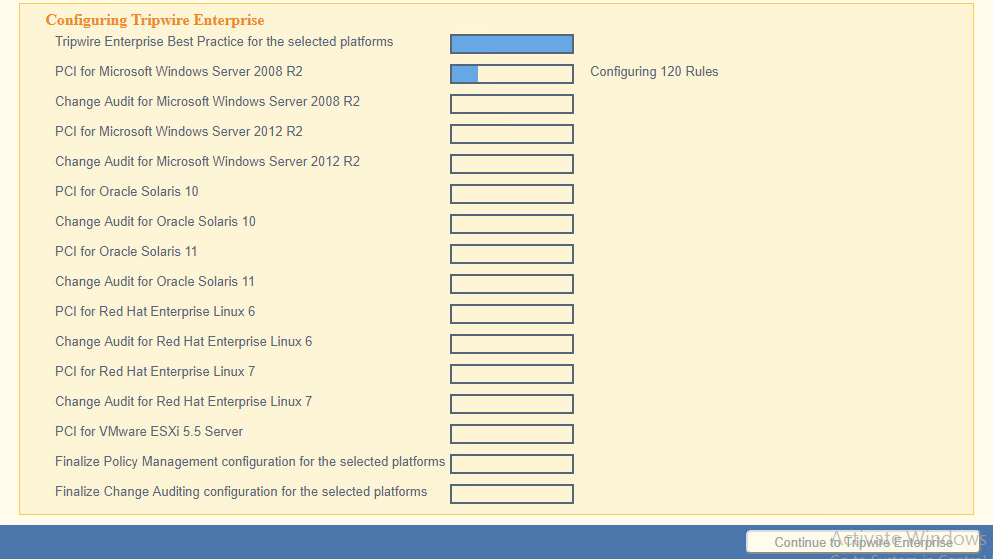
Click Configure Tripwire Enterprise.

Click Choose File and select the Tripwire Enterprise license file, which should be a .cert file.
Check the boxes next to Change Auditing and Policy Management.
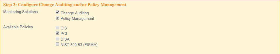
Select any available policies desired.
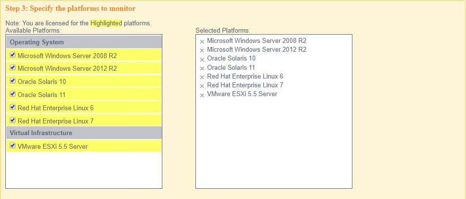
Select all the operating systems that you wish to monitor with Tripwire Enterprise.
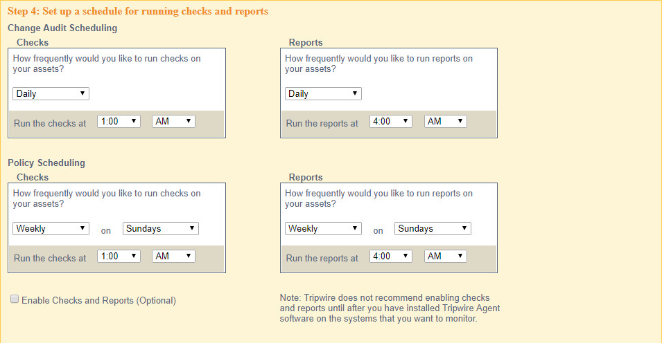
Set up a schedule for running checks and reports according to your organization’s needs. Leave the box next to Enable Checks and Reports unchecked for now.
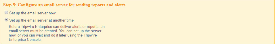
Select Set up the email server at another time.
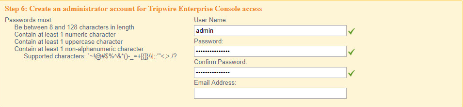
Enter a username and password for a new administrator account for Tripwire Enterprise Console.

Click Preview Configuration.
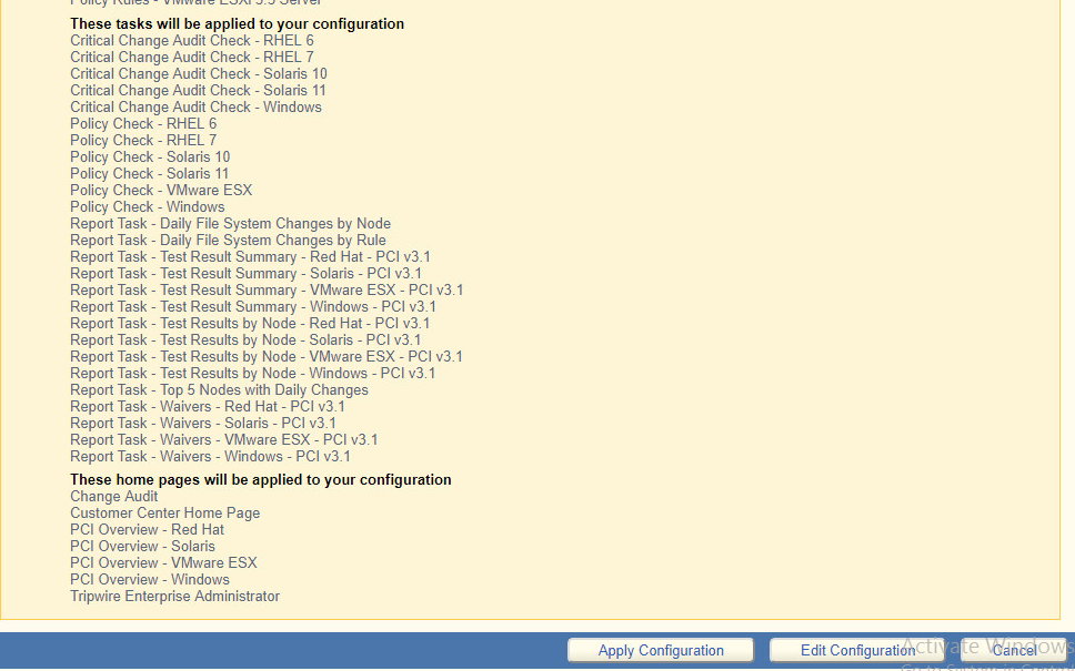
Click Apply Configuration.
Click Continue to Tripwire Enterprise when the installation finishes.
2.12.2 Install the Axon Bridge
Ensure that TCP traffic on port 5670 is allowed through the firewall.
Navigate to the Tripwire Enterprise Console installation directory to the /server/data/config folder. Copy bridge_sample.properties to bridge.properties.
In the bridge.properties file, find the line that says:
#tw.cap.bridge.registrationPreSharedKey=Remove the “#” character. After the “=” character, enter a password. The password has some restrictions, so ensure that it meets the requirements in case the connection fails later.
Restart the TE console by running the following command from an administrative command prompt, where <te_root> is the TE installation directory:
> <te_root>/server/bin/twserver restart
2.12.3 Install the Axon Agent (Windows)
Download the Axon Agent zip file from the Tripwire customer website (https://tripwireinc.force.com/customers), under the Product Downloads tab.
Unzip the file.
To begin the installation, double-click the .msi file in the extracted folder. Note: No installation wizard will appear; the installation happens automatically.
After the Axon Agent is installed, navigate to C:\ProgramData\Tripwire\agent\config, and copy twagent_sample.conf to twagent.conf.
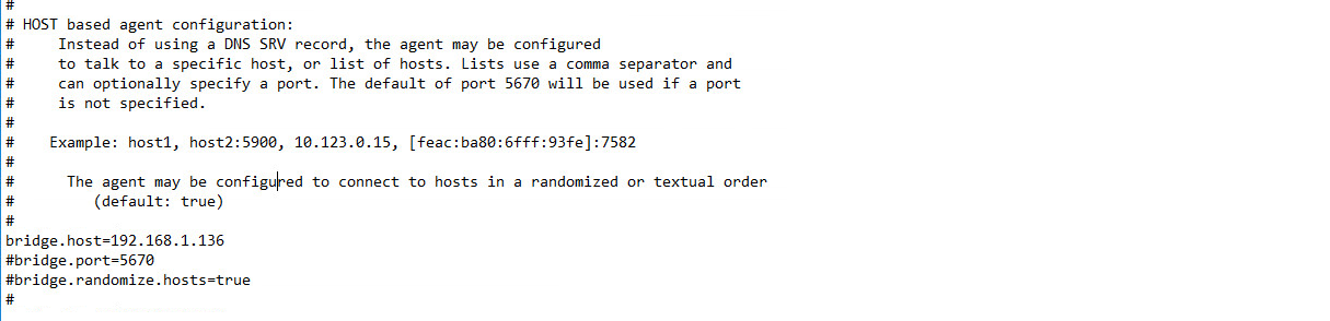
Open twagent.conf and find the line that says
bridge.host. Remove the “#” character, and enter the hostname or IP address of the Axon Bridge server.In a file called registration_pre_shared_key, enter the value of the preshared key that was set in the Axon Bridge.
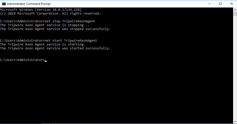
Restart the Axon Agent Service by opening a command prompt and running the following commands:
> net stop TripwireAxonAgent

> net start TripwireAxonAgent
2.12.4 Install the Axon Agent (Linux)
Download the Axon Agent .tgz file from the Tripwire customer website (https://tripwireinc.force.com/customers), under the Product Downloads tab.
To install the software, run the following commands:
RHEL or CentOS:
> rpm -ivh <installer_file>Debian or Ubuntu:
> dpkg -i <installer_file>Navigate to /etc/tripwire/ and copy twagent_sample.conf to twagent.conf.
Open twagent.conf and find the line that says bridge.host. Remove the “#” character and enter the hostname or IP address of the Axon Bridge server.
In a file called registration_pre_shared_key.txt, enter the value of the preshared key that was set in the Axon Bridge.
Restart the Axon Agent Service by opening a command prompt and running the following commands:
RHEL or CentOS:
> /sbin/service tripwire-axon-agent stop

> /sbin/service tripwire-axon-agent start
Debian or Ubuntu:
> /usr/sbin/service tripwire-axon-agent stop

> /usr/sbin/service tripwire-axon-agent start
2.12.5 Configure Tripwire Enterprise
2.12.5.1 Terminology
Node: a monitored system, such as a file system, directory, network device, database, or virtual infrastructure component
Element: a monitored object, which is a component or property of a node being audited by TE
Element Version: a record of an element’s state at specific points in time. Multiple element versions create a historical archive of changes made to the element.
Rule: A rule identifies one or more elements to the TE Console.
Action: an object that initiates a response to either changes detected by TE or by failures generated from policy tests
Task: a TE operation that runs on a scheduled or manual basis
TE Policy: a measurement of the degree to which elements comply with a policy
Policy Test: a determination of whether elements comply with the requirements of a policy
Baseline: the act of creating an element that reflects the current state of a monitored object (also called the current baseline). When a node’s baseline is promoted, TE saves the former baseline as a historic baseline.
Version Check: a check on monitored objects/elements. It is a comparison of the current state of the element against its already recorded baseline for changes.
2.12.5.2 Tags
In Tripwire Enterprise, tags can be used to label and target specific nodes. Tags are not required but allow for targeting nodes more granularly than by the operating system. This section describes how to create and assign tags.
Navigate to the TE Console in your browser.
Click Asset View.
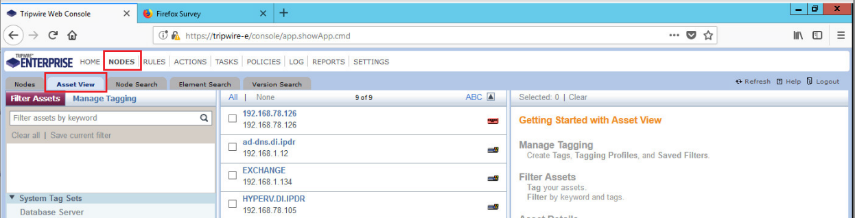
Click the Manage Tagging tab.
Enter the name of a tag set, or use one of the four existing ones (Location, Owner, Platform Family, Primary Function). Click Add if adding your own tag set.
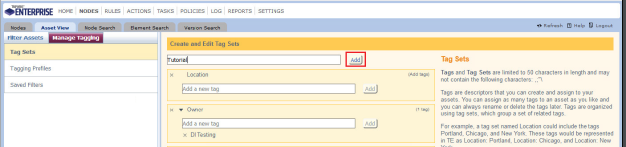
Under the tag set to which you wish to add a tag, enter the name of the tag.
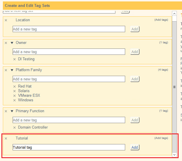
Click Add.
Navigate to Nodes > Asset View > Filter Assets.
Check the boxes next to the nodes to which you wish to add this tag.
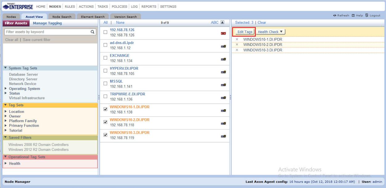
Click Edit Tags.
Check the boxes next to any tags you wish to add to these nodes.
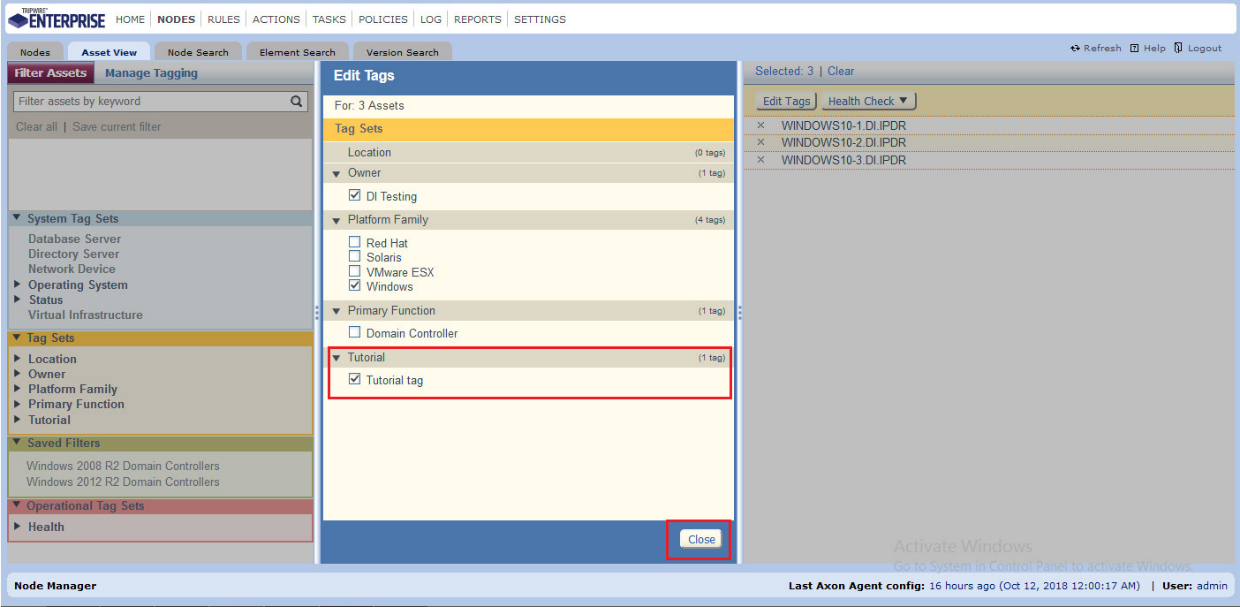
Click Close.
2.12.5.3 Rules
This section describes how to create a rule.
Click Rules.

Select or create a rule group into which the new rule should be put.
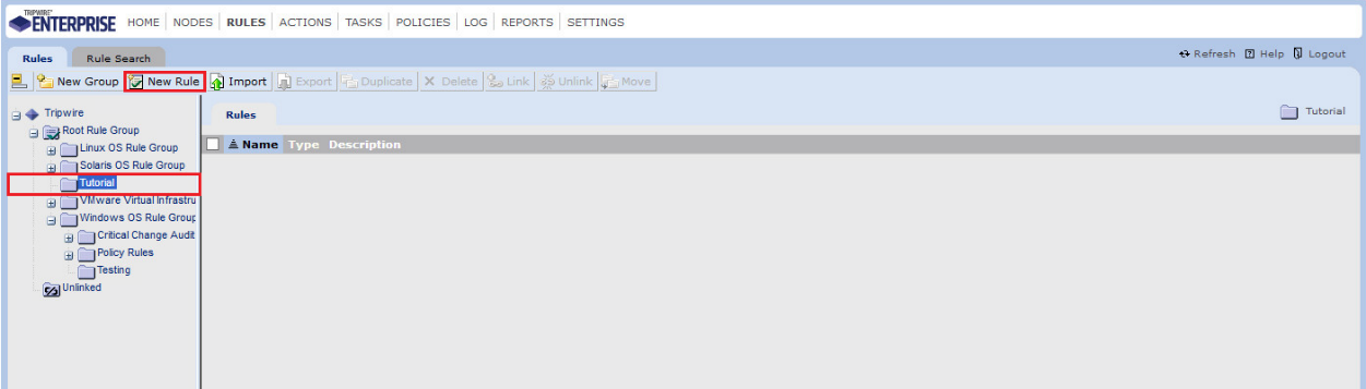
Click New Rule.
Select the type of rule. For monitoring Windows file systems, we choose Windows File System Rule.
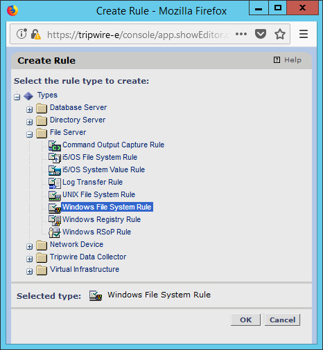
Click OK.
Enter a name and description for the rule.
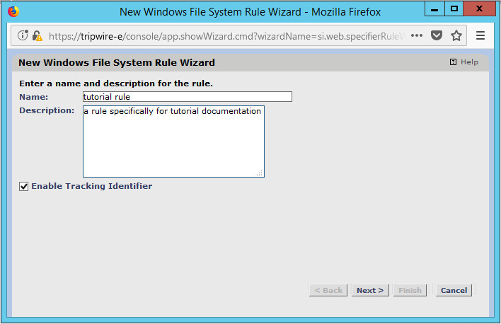
Click Next.
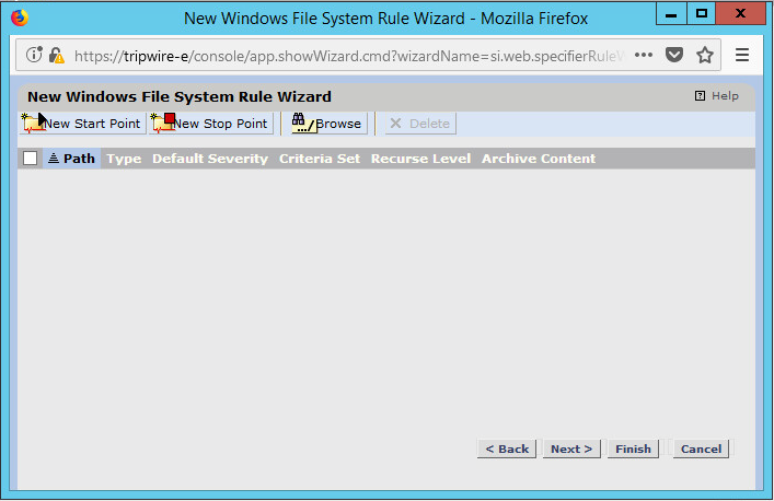
Click New Start Point.
For Path, enter a directory that represents the scope of the scan. It can be limited to the documents folder or be wide enough to encompass all the files on a system. Note that the latter will take much longer to scan.
Check the box next to Recurse directory if you also wish to scan all subfolders.
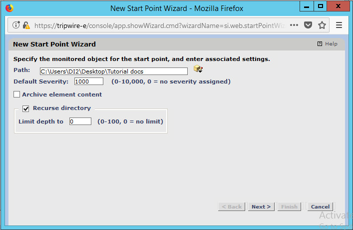
Click Next.
Select Windows Content and Permissions.
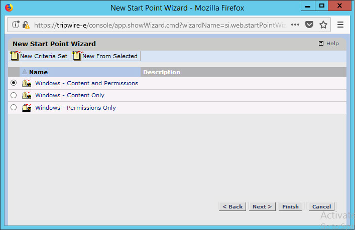
Click Finish.
Click New Stop Point.
Enter the path of any folders or files that should not be included in the scan, and indicate whether they should end the recursion.
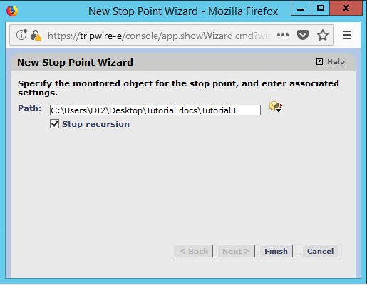
Click Finish.
Click Next.
Click Next.
Click Finish.
2.12.5.4 Tasks
This section describes how to create a task on a schedule. These tasks can also be run manually if necessary.
Click Tasks.

Select a folder for a new task, or create one.
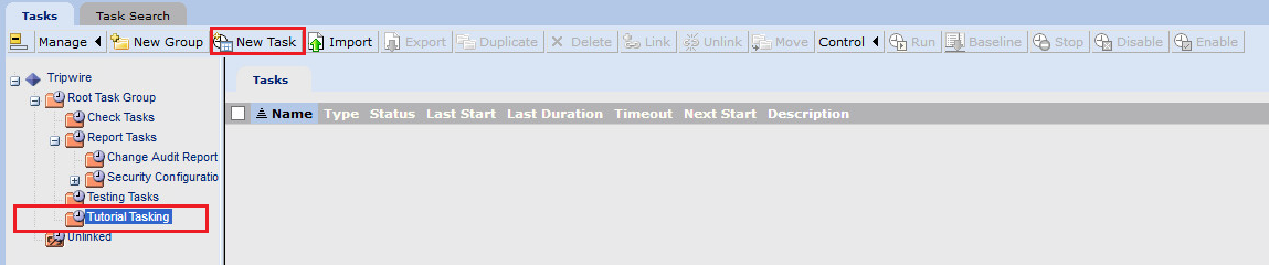
Click New Task.
Select Baseline Rule Task or Check Rule Task. (Note: Both are needed–baseline creates the initial state of the monitored object, and check updates the state and reports any changes.)
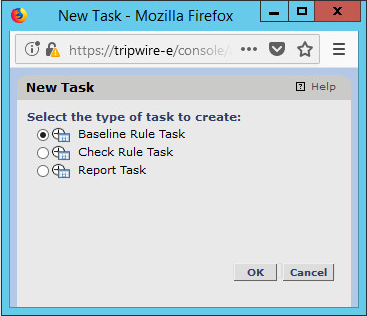
Click OK.
Enter a name and description for the task.
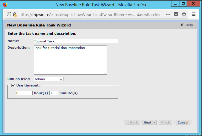
Click Next.
Select whether you want all baselines to be updated or to only create new baselines.
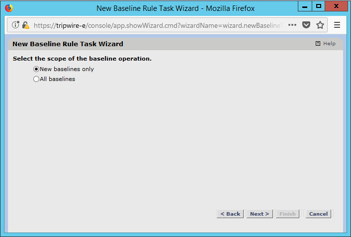
Click Next.
Select the systems to be included in the task. You can use tags or select by operating system (or other defaults).

Click Next.
Select the rule created earlier.
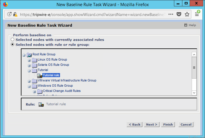
Click Next.
Set the schedule of this task according to your organization’s needs.
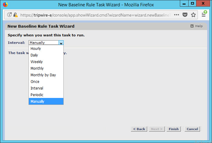
Click Finish.
2.13 Tripwire Log Center
2.13.1 Install Tripwire Log Center Manager
See the Tripwire Log Center 7.3.1 Installation Guide, which should accompany the installation media, for instructions on how to install Tripwire Log Center. Use the Tripwire Log Center Manager installer.
Notes:
It is recommended that you install Tripwire Log Center on a separate system from Tripwire Enterprise.
You will need to install JRE8 and the Crypto library. Instructions are also in the Tripwire Log Center 7.3.1 Installation Guide.
.NET Framework 3.5 is required for this installation–install this from the Server Manager.
You may need to unblock port 9898 on your firewall for the Tripwire Enterprise agents.
Do not install PostgreSQL if you wish to use a database on another system–this guide will use a local PostgreSQL database, however.
When it finishes installing, there should be a configuration wizard (see below for configuration steps).
2.13.2 Configure Tripwire Log Center Manager
The configuration wizard should start after the installation is complete.
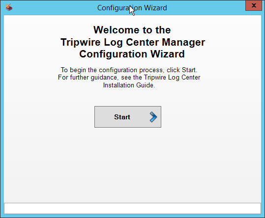
Click Start.
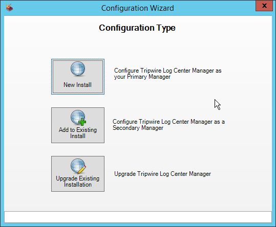
Click New Install.
Enter the registration details for your Tripwire Log Center license.
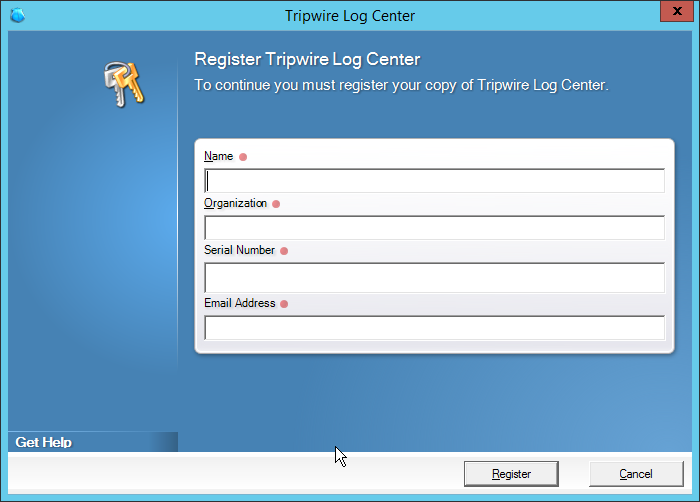
Click Register.
Enter details about the database that Tripwire Log Center should use.
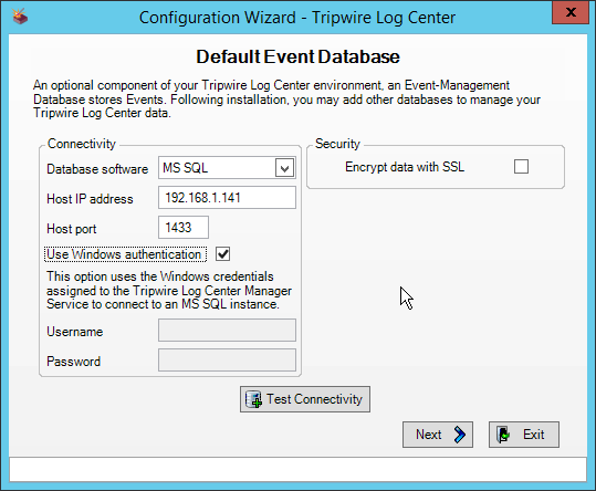
Click Next.
Select a directory in which to store log messages, such as C:\Program Files\Tripwire\Tripwire Log Center Manager\Logs\AUDIT.
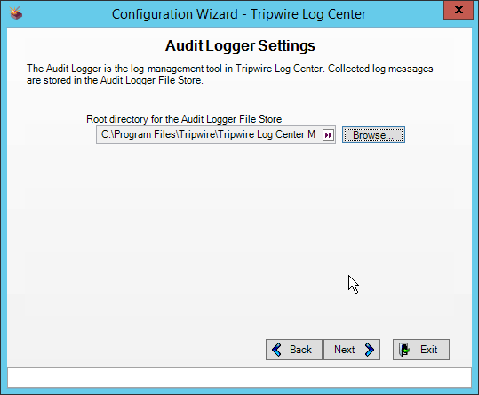
Click Next.
Enter a password and an email.
Change the IP to a hostname if preferred.
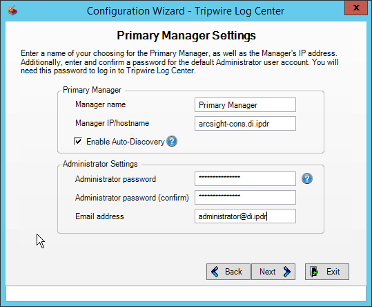
Click Next.
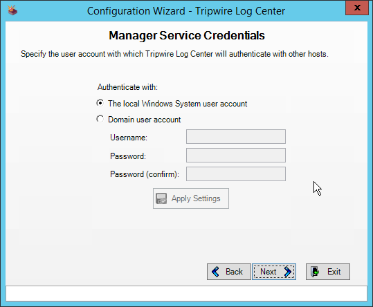
Click Next.
Select any log sources that you expect to collect with Tripwire Log Center. Examples: Tripwire Enterprise, Microsoft Windows 10, Tripwire IP360 VnE, Linux Debian, Ubuntu Linux, Microsoft Exchange, Microsoft SQL Server.
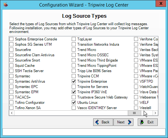
Click Next.
Click Start.
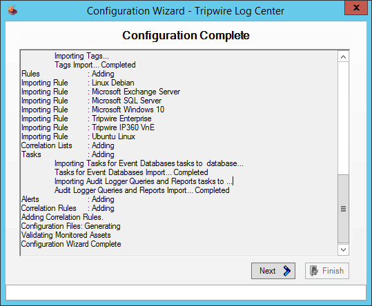
Click Next.
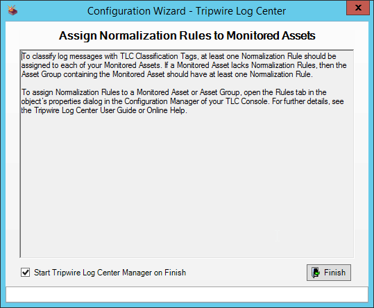
Click Finish.
2.13.3 Install Tripwire Log Center Console
Chapter 4 of the Tripwire Log Center 7.3.1 Installation Guide details installation of the Tripwire Log Center Console. Use the Tripwire Log Center Console installer.
You can install this on the same machine as the Tripwire Log Center Manager, if desired.
2.14 Cisco Web Security Appliance
This section details installation and some configurations for the Cisco Web Security Appliance (WSA). It assumes the use of the WSA virtual machine.
2.14.1 Network Configuration
Log in to WSA by using the default username and password (admin/ironport).
Use the command
sethostnameto set the hostname of the machine.Use the command
dnsconfigto set the DNS server. Enter SETUP when prompted, and then enter DNS information specific to your organization’s needs.Use the command
interfaceconfigto set the IP of the machine. Enter EDIT when prompted, and then enter IP information specific to your organization’s needs.Use the command
passwdto change the default password of the machine.Use the command
committo commit all of these changes.Use the command
rebootto reboot the machine.Use the command
loadlicenseto either paste the license file contents or select a license file uploaded via FTP. You can enable FTP in theinterfaceconfigcommand.You should be prompted at the console to visit a web page in the browser, usually http://<ip_address>:8080. The setup wizard will be here.
2.14.2 System Setup
In the web console, click System Administration > System Setup Wizard.
Verify that the hostname matches the desired hostname.
Enter the desired DNS servers.
Enter a time server if desired.
Select the time zone.
Select Standard for an on-premises setup.
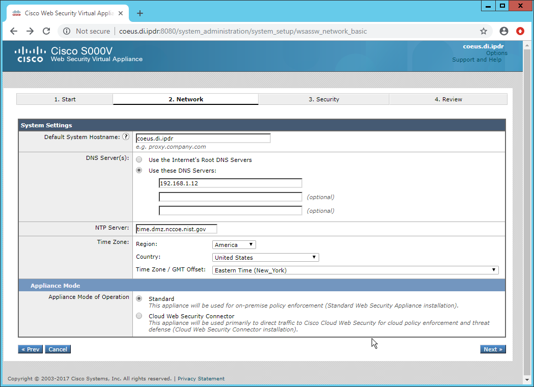
Click Next.
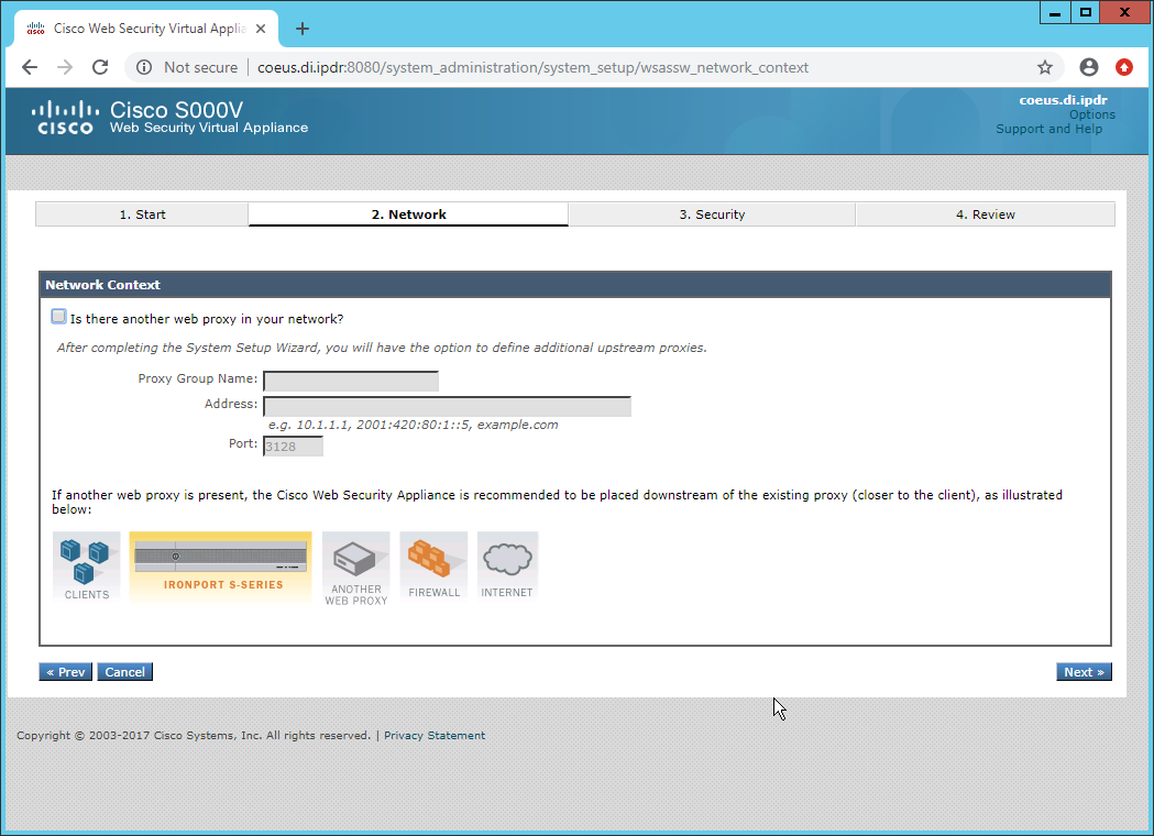
Click Next.
Verify that the interface is correctly configured.
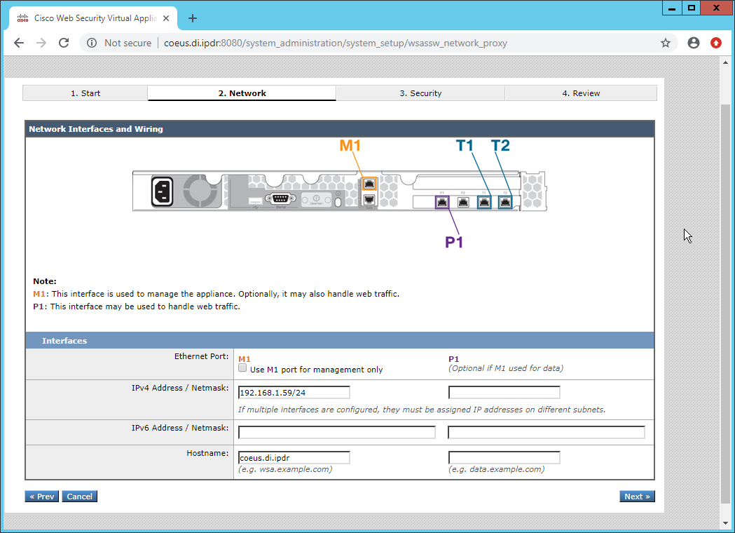
Click Next.
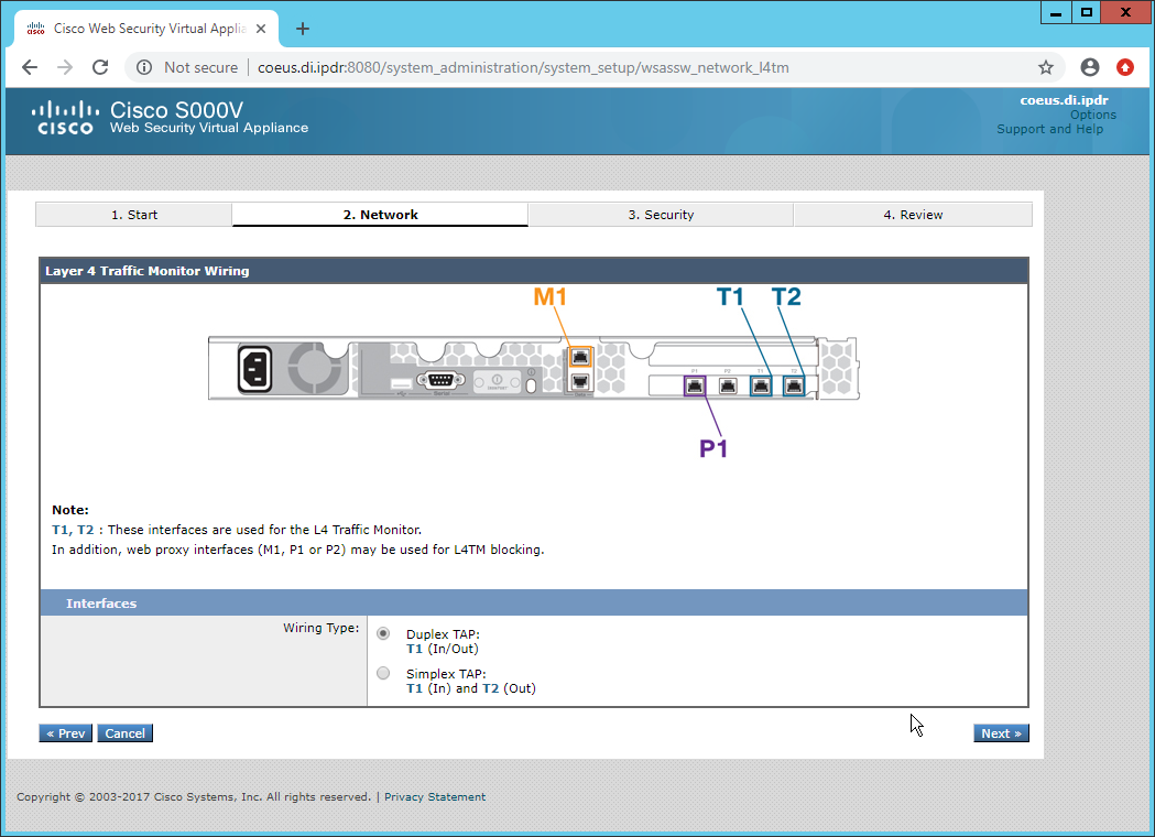
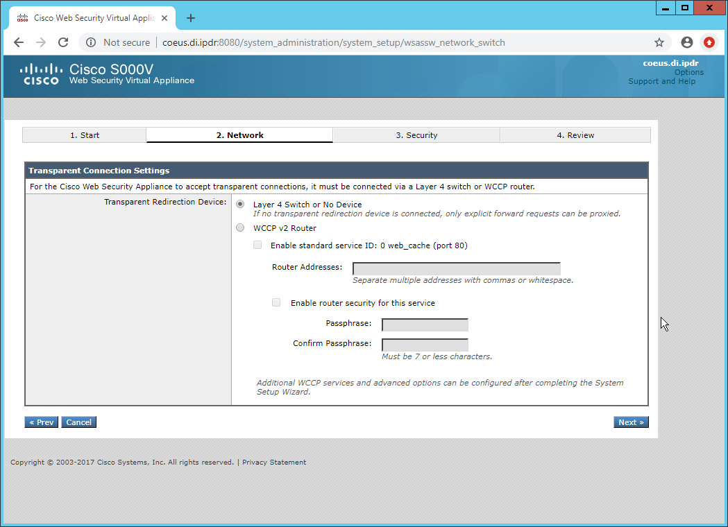
Click Next.
Enter the default gateway and any additional gateways to use for routing.
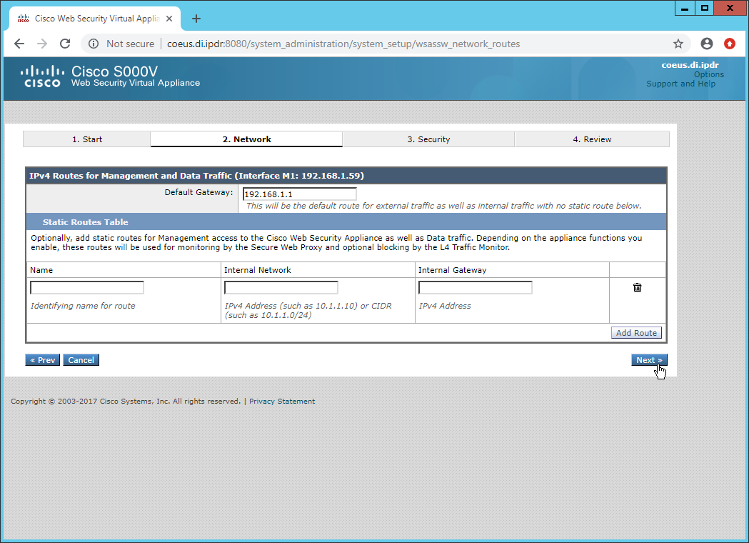
Click Next.
Click Next.
Set a passphrase for the administrator.
Enter an email address to which alerts should be sent.
Enter the hostname of the email server.
Decide whether to forward alerts and reports to Cisco Customer Support, as well as whether to share anonymous statistics based on the needs of your organization.
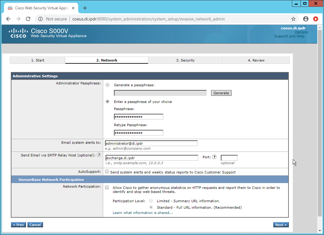
Click Next.
Select Monitor All Traffic.
Select Block for Action for Suspect Malware Addresses.
Select Block for Action for Detected Malware.
Configure the rest of the malware policy according to your organization’s needs.
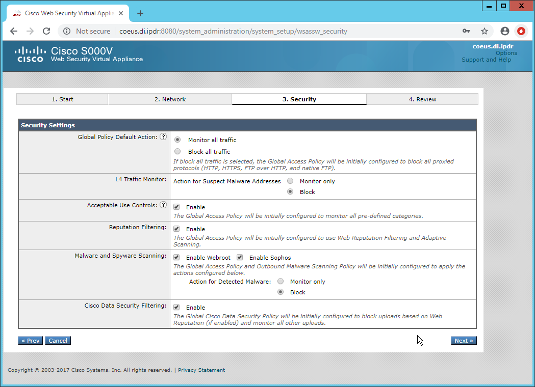
Click Next.
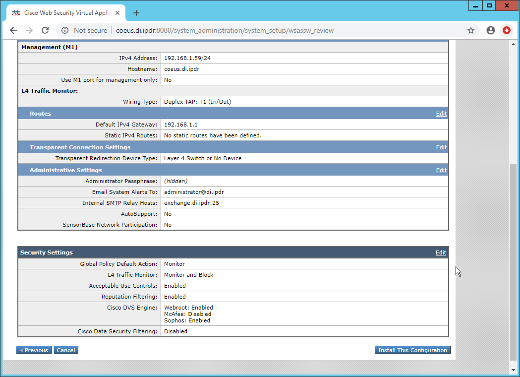
Click Install This Configuration.
2.14.3 Using WSA to Proxy Traffic
Cisco WSA is intended to act as a proxy between clients and the internet, to prevent malicious traffic and software from reaching the client systems before they can do any damage. The appliance must have a way of intercepting traffic from the clients to the internet.
To achieve this, we used a Proxy Auto Config (PAC) file on our DNS server (Windows 2012 DNS), and this section details how to set up a simple PAC file to forward all traffic to WSA. This may not be an ideal setup for every environment, particularly in environments that use an external DNS server.
2.14.3.1 Creating a PAC File
Create a new file named wpad.dat and enter the following JavaScript function:
function FindProxyForURL(url, host) {

    return "PROXY coeus.di.ipdr:3128";

}
This is the most basic template for a proxy that directs all traffic to the host coeus.di.ipdr. The return value of this function can take the form
“PROXY
<hostname1>; PROXY <hostname2>”
if you wish to have fail-over proxies, or“DIRECT”to not use any proxy. You can also add rules to allow certain types of traffic through the proxy or direct them to other proxies. For more information, see https://findproxyforurl.com.For the purposes of our setup, we will simply direct all traffic to Cisco WSA, but be aware that PAC files can be more complex and designed according to the needs of the organization.
In the web console, navigate to Security Services > Web Proxy.
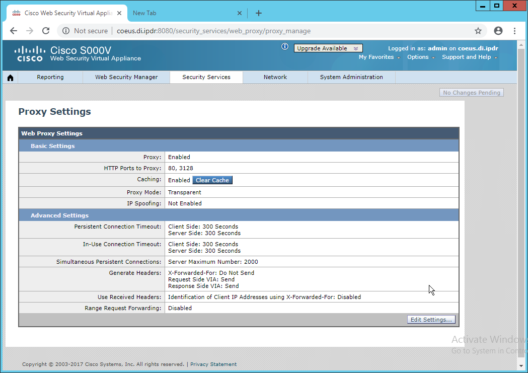
Click Edit Settings.
Remove port 80 from HTTP Ports to Proxy (ensure that 3128 is in this field).
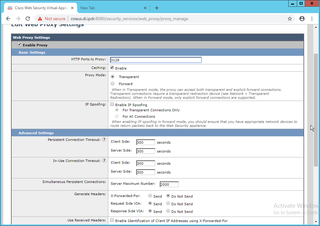
Click Submit.
Navigate to Security Services > PAC File Hosting.
Click Enable and Edit Settings.
Under PAC Files, click Choose File.
Select the wpad.dat file created earlier.
Click Open.
Click Upload.
Enter 80 for PAC Server Ports.
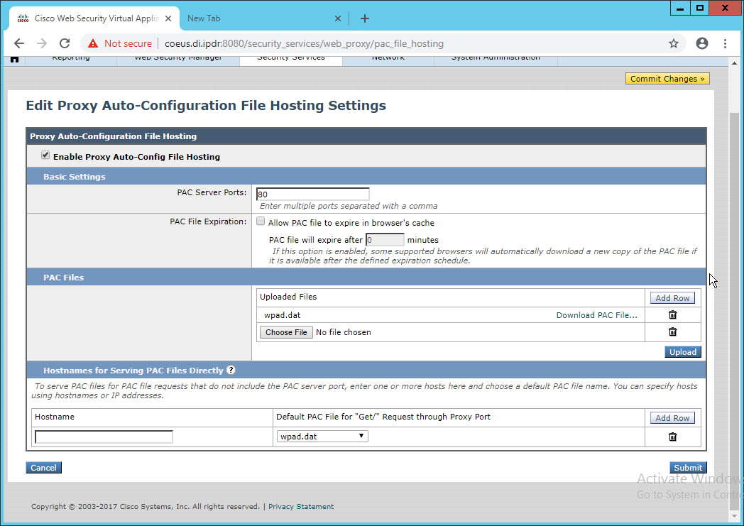
Click Submit.
Click Commit Changes.
Enter a comment if desired.
Click Commit Changes.
2.14.3.2 Setting Up Web Proxy Auto Discovery (WPAD)
On the DNS server, open regedit.exe.
Navigate to HKEY_LOCAL_MACHINE > SYSTEM > CurrentControlSet > Services > DNS > Parameters.
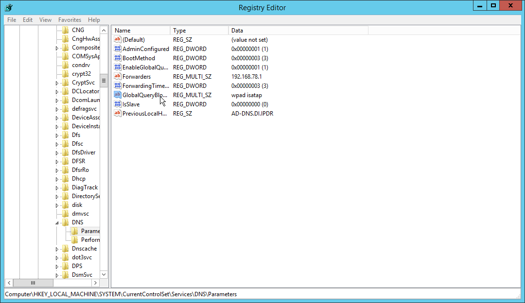
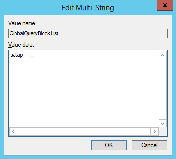
Double-click GlobalQueryBlockList.
Remove wpad from the list but leave isatap on the list.
Click OK.
Open Task Manager.
Click Services.
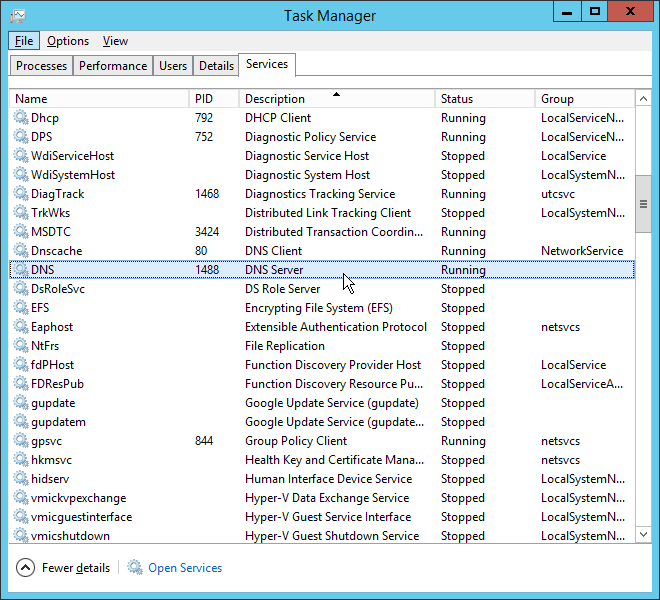
Restart the DNS Server service.
Open DNS Manager.
Right-click on your enterprise’s domain, and click New Host (A or AAAA).
Enter wpad for Name.
Enter the IP address of WSA.
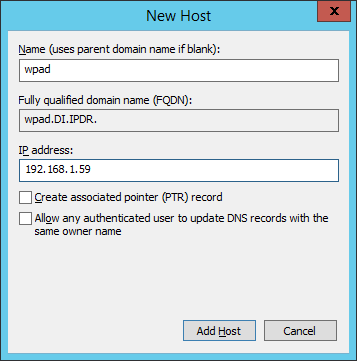
Click Add Host.
This will set up the WPAD proxy file as the default proxy–so browsers that are using “Automatically detect settings” for their proxy setting will find this file. Be aware that this is not sufficient for a secure setup but will allow you to quickly test the proxy’s functionality.
2.14.3.3 Configure Group Policy to Use Explicit Proxy
Note that, at this point, WPAD is vulnerable to an attack where the server hosting WPAD is brought down and the browser automatically attempts to find the next WPAD proxy, which may be controlled by an attacker.
To mitigate this vulnerability, we explicitly point to this proxy file with any browsers used by clients. For Internet Explorer and Google Chrome, it is sufficient to change group policy in Active Directory to direct the change across all systems.
For Mozilla Firefox, see this link (https://support.mozilla.org/en-US/kb/connection-settings-firefox) for configuration, including how to set it to “Use system proxy settings.”
In Group Policy Management, right-click the Default Domain Policy and click Edit.
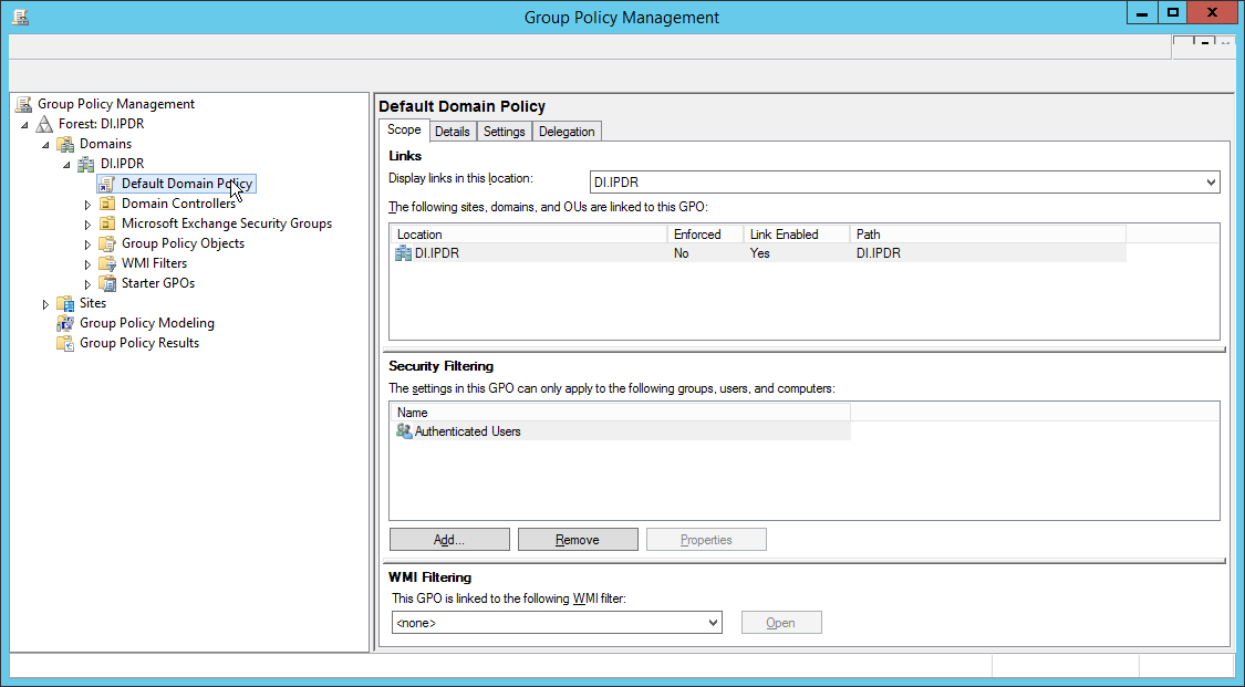
In Group Policy Management Editor, navigate to User Configuration > Preferences > Control Panel Settings > Internet Settings.
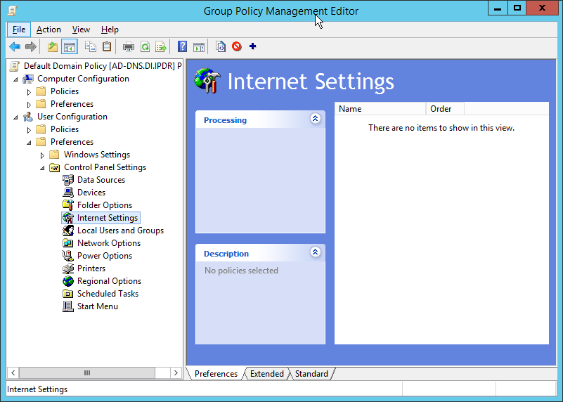
Right-click Internet Settings and select New > Internet Explorer 10.
Click the Connections tab.
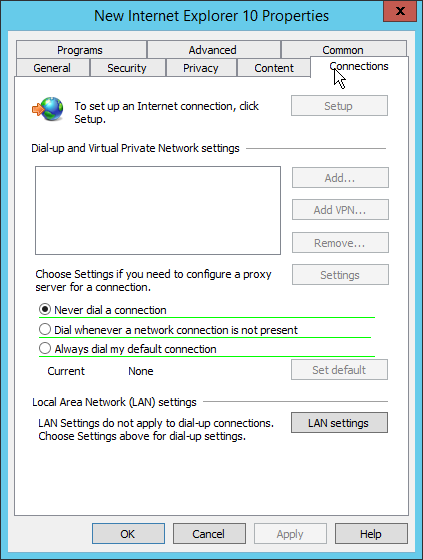
Click LAN Settings.
Enter the address of the WPAD file for address. This will likely take the form http://wpad.my.domain/wpad.dat if you followed these instructions for configuring the proxy file.
Press the F8 key to disable all settings in this dialogue box. (Note: This should underline everything in the box in red.)
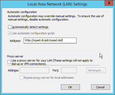
Select the Address you just entered.
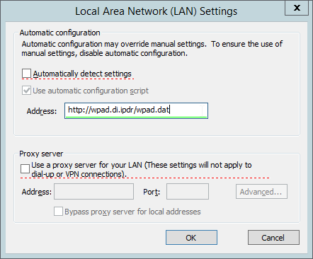
Press F6 to enable this setting. (Note: The explicit WPAD address should now be underlined in green.)
Click OK.
Click OK.
This Group Policy Object will update across all Windows systems whenever gpupdate.exe runs. An insider or technically capable user could manually disable this to avoid using the proxy, but benign clients who do not attempt to circumvent it will be protected from external (internet-based) threats by Cisco WSA. Protection from insiders and local threats on the network is provided by other products in the architecture, such as the network protection component (CryptoniteNXT).
2.14.4 Denylisting
Navigate to Web Security Manager > Custom and External URL Categories.
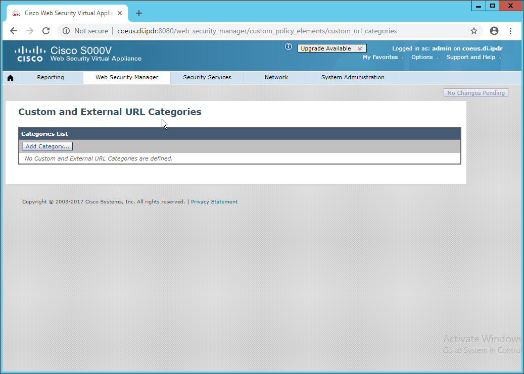
Click Add Category.
Enter a name for Category Name.
Select Local Custom Category. (The other option, External Live Feed Category, allows WSA to use a list of websites hosted somewhere else, potentially externally. For this demonstration we will simply enter websites in the Sites field, but note that this other option is available for convenience.)
For Sites, enter any sites to denylist. (Note: Entering .mysite.abc will include any subdomains of mysite.abc.)
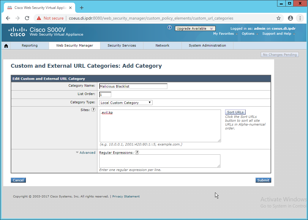
Click Submit.
Navigate to Web Security Manager > Access Policies.
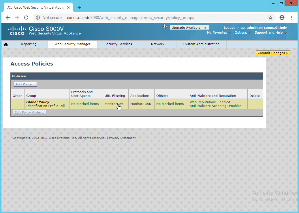
Click the link under URL Filtering.
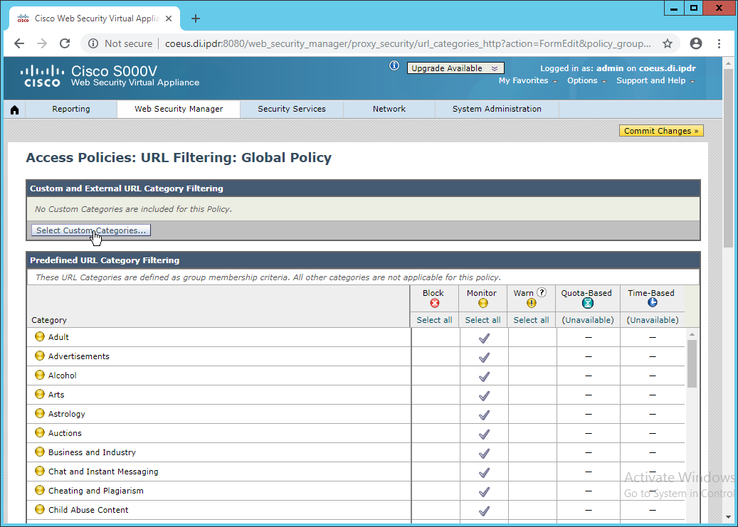
Click Select Custom Categories.
For the category just created, select Include in policy under Setting Selection.
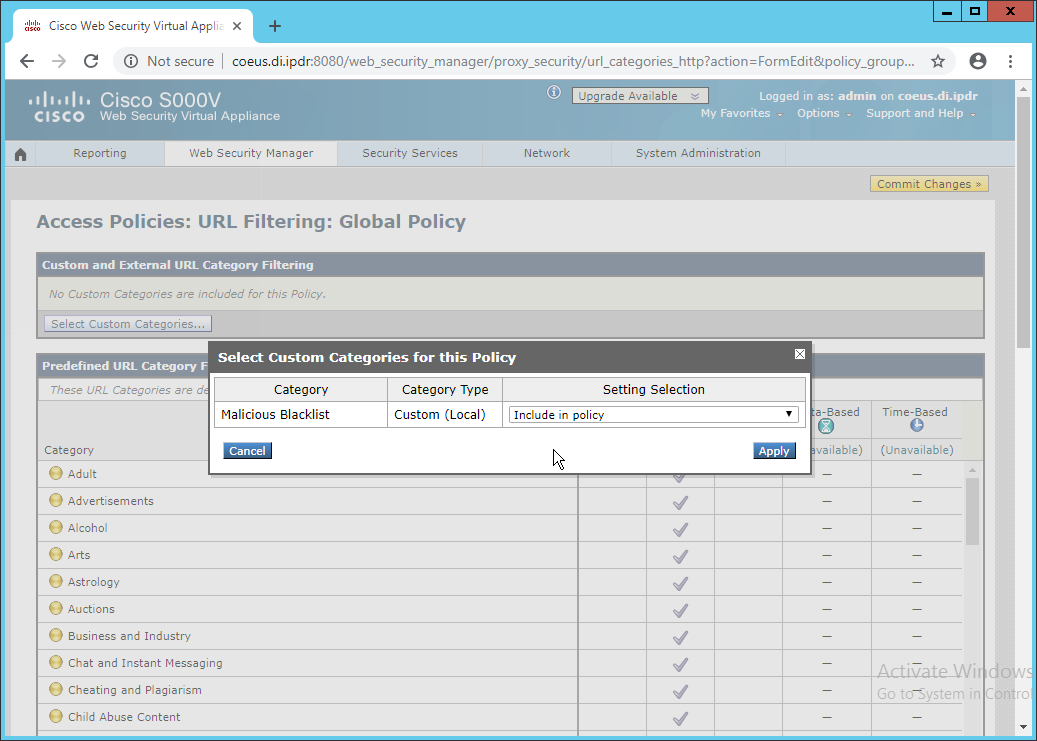
Click Apply.
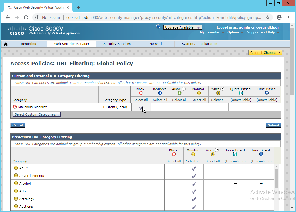
The category should now show under Custom and External URL Category Filtering. Put a checkmark in the Block box. (Selecting Allow lets you permit domains that are being incorrectly classified as malicious.)
Click Submit.
Click Commit Changes.
Enter a comment if desired.
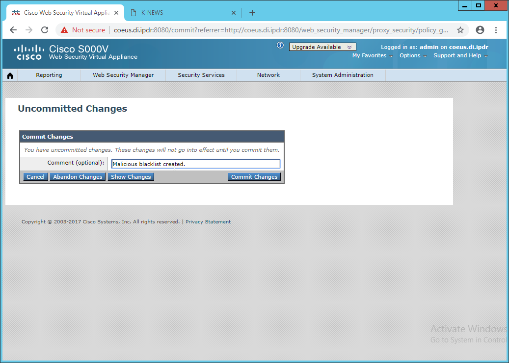
Click Commit Changes.
2.15 Symantec Data Loss Prevention
2.15.1 Install Oracle 12c Enterprise
Unzip the Symantec DLP installation files.
Download the Oracle 12c installation files from https://www.oracle.com if they are not included with the Symantec DLP installation files.
Move both sets of installation files to a temporary directory, such as C:\temp.
Copy the Symantec 12.2.0.1_64_bit_Installation_Tools folder to C:\temp\Oracle\tools.
From a command prompt, navigate to C:tempOracledatabase, assuming the Oracle installation files were unzipped to C:tempOracle.
Run the following command:
> C:\temp\Oracle\database\setup.exe -noconfig -responsefile C:\temp\Oracle\tools\responsefiles\Oracle_12.2.0.1_Enterprise_Edition_Installation_WIN.rsp
Once the wizard opens, you will be asked to configure security updates. If you do not possess a My Oracle Support account, leave the box unchecked and provide an email.
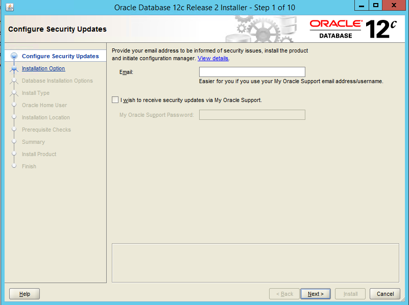
Click Next.
Select Install database software only.
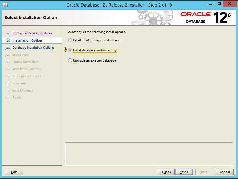
Click Next.
Select Single instance database installation.
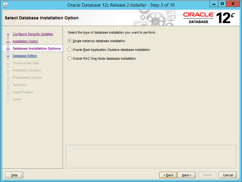
Click Next.
Select Standard Edition.
Click Next.
Select Create New Windows User.
Enter the username and password of a new user for Active Directory.
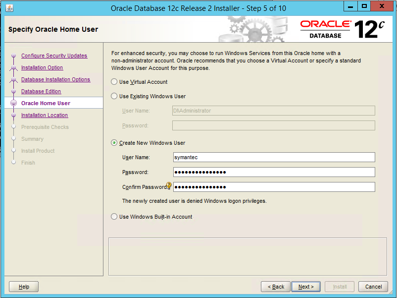
Click Next.
Select a location to install the software, if desired.
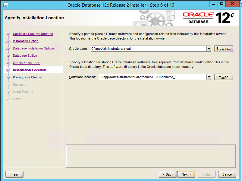
Click Next.
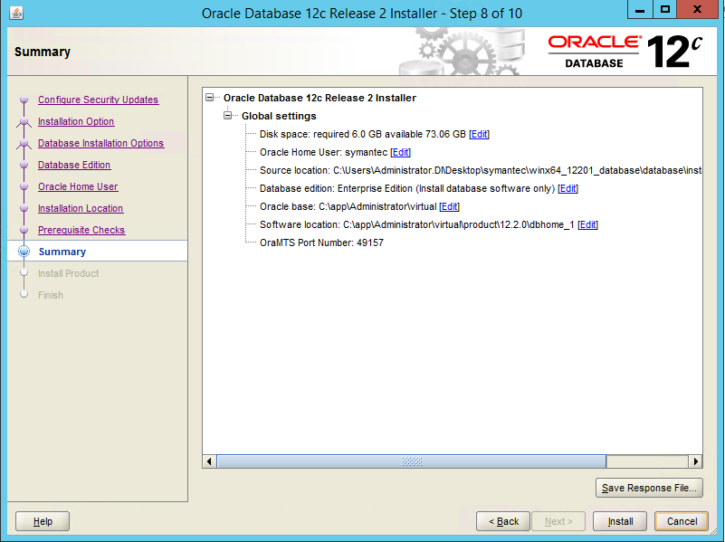
Verify the information and click Install. The installation may take a long time.
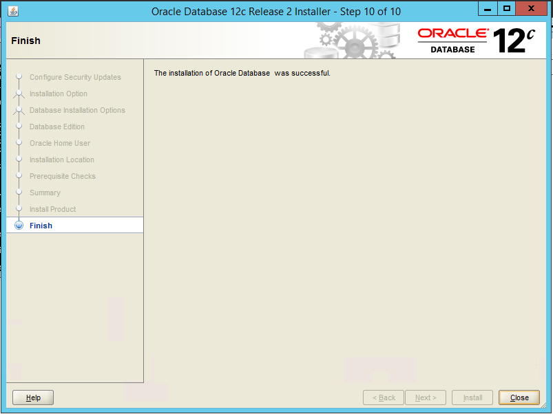
Click Close when the installation is complete.
2.15.2 Create an Oracle Database for Symantec DLP
Set the ORACLE_HOME environment variable by running the following command. Adjust the path accordingly if using a version other than 12.2.0.
> set ORACLE_HOME=C:\app\Administrator\virtual\product\12.2.0\dbhome_1Copy the Oracle database template named Oracle_12.2.0.1_Template_for_64_bit_WIN.dbt from the Symantec DLP zip file into C:\app\Administrator\virtual\product\12.2.0\dbhome_1\assistants\dbca\templates.
Ensure that the response file Oracle_12.2.0.1_DBCA_WIN.rsp is located in the folder C:\temp\Oracle\database\tools\responsefiles.
Run the following command.
> %ORACLE_HOME%\bin\dbca -createDatabase -progressOnly -responseFile C:\temp\Oracle\database\tools\responsefiles\Oracle_12.2.0.1_DBCA_WIN.rsp
Enter a password for the SYS user. (Only the special characters _, #, or $ are allowed.)
Enter a password for the SYSTEM user. (Only the special characters _, #, or $ are allowed.)
Enter a password for the Oracle Home User.
2.15.3 Configuring the Oracle Listener
Ensure that the database services OracleServicePROTECT and DistributedTransactionCoordinator are running.
In the file %ORACLE_HOME%\network\admin\sqlnet.ora, change the line SQLNET.AUTHENTICATION_SERVICES=(NTS) to SQLNET.AUTHENTICATION_SERVICES=(none).
Navigate to Start > All Programs > Oracle 12.2.0 > Configuration and Migration Tools > Net Configuration Assistant and run the program.
Select Listener configuration.
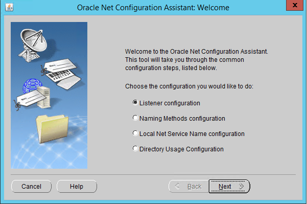
Click Next.
Select Add.
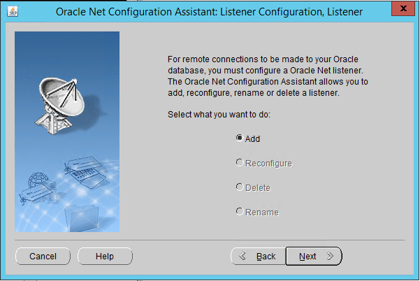
Click Next.
Enter a name for the listener.
Enter a password.
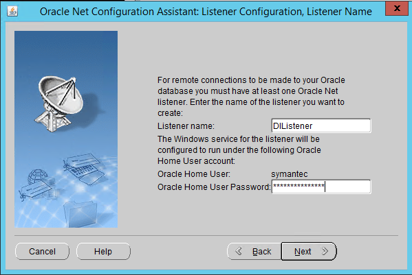
Click Next.
Move the TCP protocol to the Selected Protocols column.
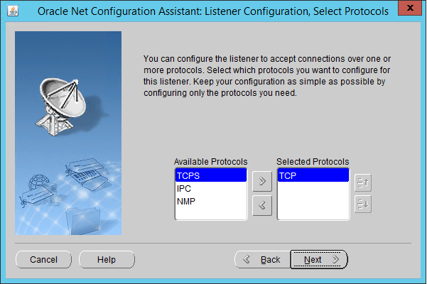
Click Next.
Select Use the standard port number of 1521.
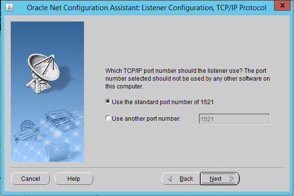
Click Next.
Select No.
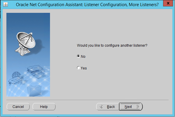
Click Next.
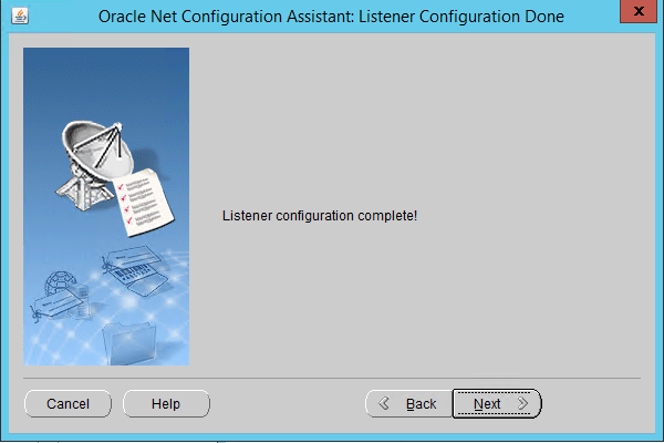
Click Next.
Select Local Net Service Name configuration.

Click Next.
Select Add.
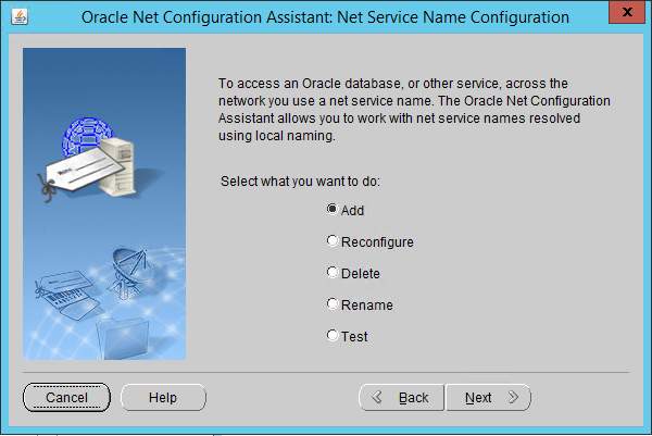
Click Next.
Enter the word “protect” for the name.
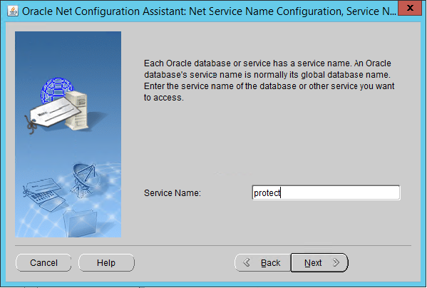
Click Next.
Select TCP.
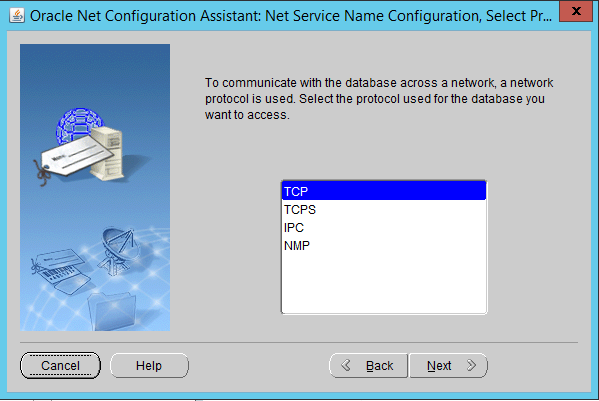
Click Next.
Enter the IP address of the system hosting the Oracle Database.
Select Use the standard port number of 1521.
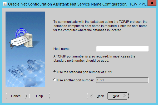
Click Next.
Select No, do not test.
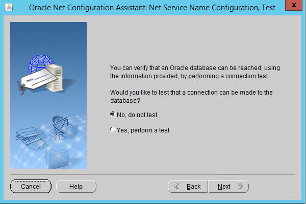
Click Next.
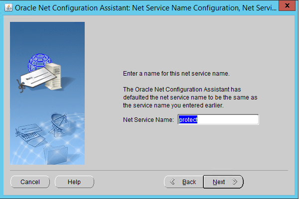
Click Next.
Select No.
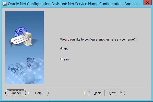
Click Next.
Click Next.
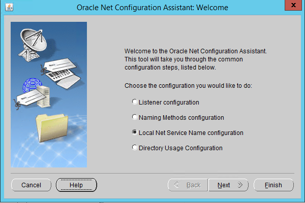
Click Finish.
In an administrative command prompt, run the following command to stop the listener.
> lsnrctl stopOpen the file %ORACLE_HOME%\network\admin\listener.ora.
Change (ADDRESS = (PROTOCOL = IPC)(KEY = <key_value>)) to (ADDRESS = (PROTOCOL = IPC)(KEY = PROTECT)).
Add the line SECURE_REGISTER_LISTENER=(IPC) to the end of the file.
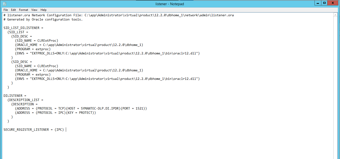
Save the file and exit the editor.
Ensure that OracleServicePROTECT and OracleVssWriterPROTECT services are running in Task Manager.
In an administrative command prompt, run the following command to start the listener. Replace dilistener with the name given to your listener.
> lsnrctl start dilistenerRun the following commands to connect the listener to the database using SQL Plus. Replace password with the password used for the SYS user.
> sqlplus /nolog

> conn sys/password as sysdba
Run the following commands in the SQL prompt. (Note: If errors occur relating to the SPFILE, try replacing ORACLE_HOME or ORACLE_base values in %ORACLE_HOME%\dbs\init.ora with the absolute path. Then run CREATE SPFILE FROM PFILE=’%ORACLE_HOME%\dbs\init.ora’ and CREATE PFILE FROM SPFILE=’%ORACLE_HOME%\dbs\init.ora’. Restart the database after doing this.)
> ALTER SYSTEM SET local_listener = '(DESCRIPTION=(ADDRESS=(PROTOCOL=ipc)(KEY=PROTECT)))' SCOPE=both;

> ALTER SYSTEM REGISTER;

> exit
Run the following command to verify the status of the listeners:
> lsnrctl services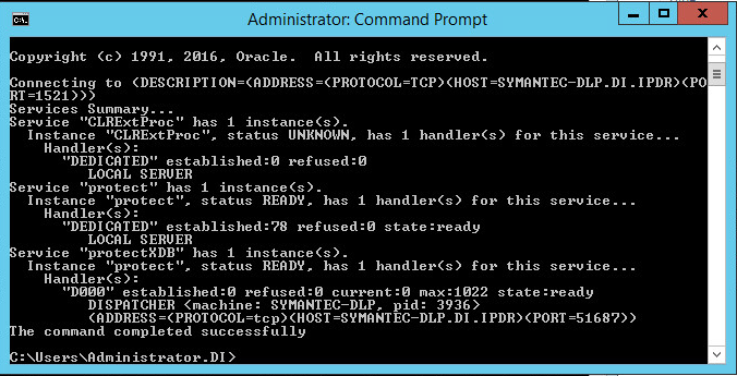
Open a new administrative command window.
Navigate to C:\Temp\Oracle\database\tools.
Run the following command:
> sqlplus /nolog

> @oracle_create_user.sql
Enter the password for the SYS user.
For sid, enter “protect”.
For a username, enter “protect”.
Enter a password for the “protect” user. (The special characters &, $, and # are not allowed.)
When this process is finished, open a new administrative command window and run the following command.
> sqlplus /nologLog in as the SYS user with the following command (replace “password” with the password for the SYS user).
> connect sys/password@protect as sysdaVerify the version information with the following command.
> SELECT * FROM v$version;
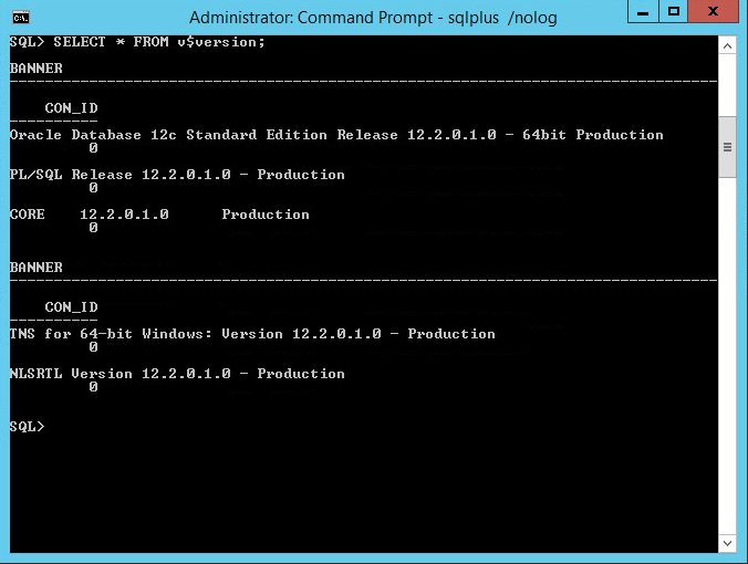
2.15.4 Install Symantec DLP
In the folder DLP Installs\DLP 15.1\Symantec_DLP_15.1_Platform_Win-IN_15.1.0.25021\DLP\15.1\New_Installs\x64\Release, located in the download folder for the DLP files, run ServerJRE.msi.
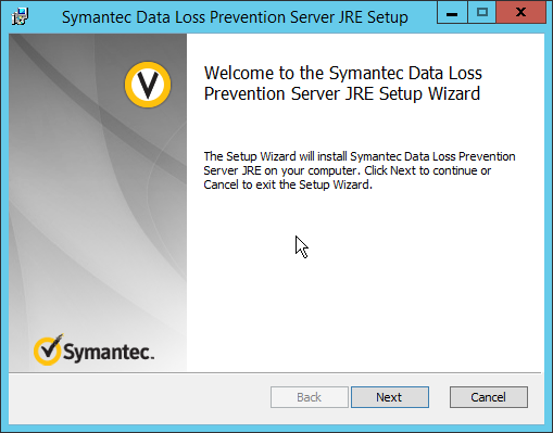
Click Next.
Select I agree to the terms in the license agreement.

Click Next.
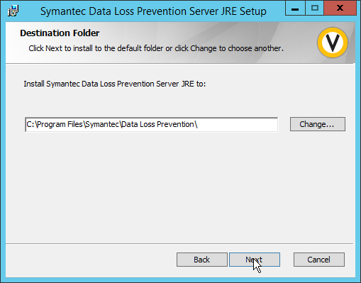
Click Next.
Click Install.
Click Finish.
Run SingleTierServer.msi (located in the same folder as ServerJRE.msi).
Click Next.
Check the box to accept the license agreement.
Click Next.
Click Next.
Select Enabled for FIPS 140-2 Compliant Algorithms.
Click Next.
Click Next.
Click on New Users.
Click Next.
Enter a password and optionally a username.
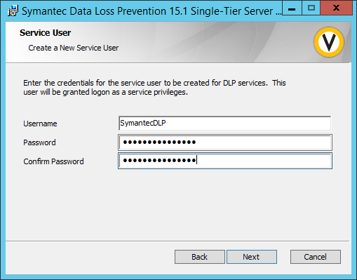
Click Next.
Enter a password and optionally a username.
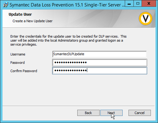
Click Next.
Enter the password used for the “protect” user.
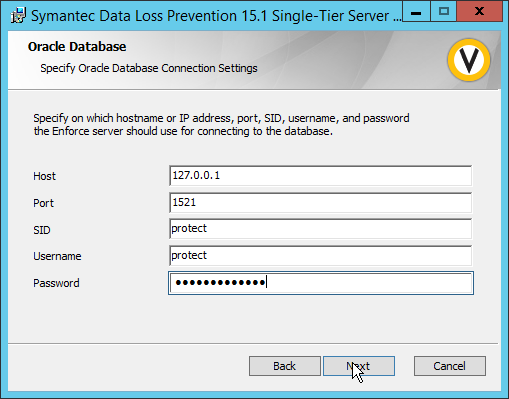
Click Next.
Select Initialize Database.
Click Next.
Set the initial password for logging into the Enforce Administrator account.
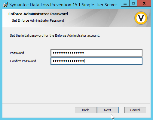
Click Next.
Select Database.
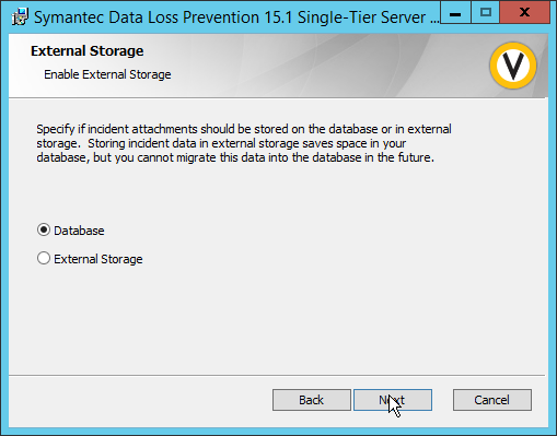
Click Next.
Select None.
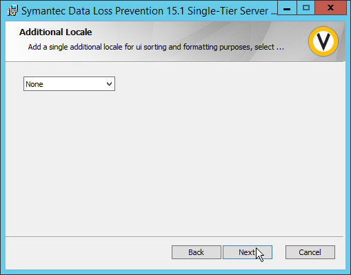
Click Next.
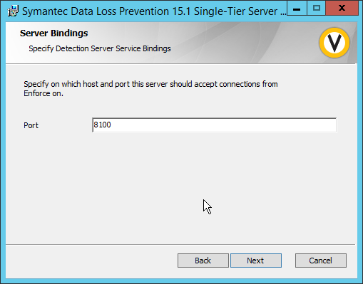
Click Next.
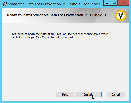
Click Install.
Click Finish.
Ensure that the services are running in Task Manager:
SymantecDLPManager
SymantecDLPIncidentPersister
SymantecDLPNotifier
SymantecDLPDetectionServer
2.15.5 Configure Symantec DLP
Navigate to https://127.0.0.1 in the browser to get to the Symantec DLP web console.
Navigate to System > Settings > General and click Configure.
In the Edit General Settings screen, upload your license file provided by Symantec.
Click Save.
In Task Manager, stop the SymantecDLPManager service.
Copy the classpath.txt file located in <DLP Download Home>\DLP\15.1\Solution_Packs\ and overwrite the classpath.txt located at C:\Program Files\Symantec\Data Loss Prevention\Enforce Server\15.1\Protect\Config\SolutionPackInstaller.
In an administrative command window, use the following commands to import the chosen solution pack. For example, to import the financial solution pack, use:
> cd “C:\Program Files\Symantec\Data Loss Prevention\Enforce Server\15.1\protect\bin”

> .\SolutionPackInstallerexe import “C:\Program Files\Symantec\Data Loss Prevention\Financial_v15.1.vsp”
After this is installed, restart the SymantecDLPManager service.
Log on to the Enforce Web Console as Administrator.
Navigate to System > Servers > Overview.
Click Add Server.
Select the type of Detection Server to add.
Click Next.
Enter a name.
Enter the hostname of the DLP server.
Enter 8100 for the port.
Navigate to System > Settings > General.

Check the box next to Advanced Process Control.
Specify any configuration options according to the needs of your organization.
Click Save.
2.16 Cisco Identity Services Engine
This section details the installation and some configurations for the Cisco Identity Services Engine (ISE). It assumes the use of the ISE virtual machine.
2.16.1 Initial Setup
When prompted to log in for the first time, enter
setup. (You can use the commandreset-configto change these values later.)Enter the desired hostname for the machine.
Enter the desired IP address for the machine. (Ensure that the specified hostname is associated with this IP address in your DNS.)
Enter the netmask for the machine.
Enter the default gateway.
Enter the default DNS domain (the name of your domain).
Enter the primary nameserver (the IP address of your DNS).
Enter a second nameserver if desired.
Enter a Network Time Protocol (NTP) time server.
Enter the timezone.
Enter Y for SSH service.
Enter an administrator username for the machine.
Enter a password twice.
2.16.2 Inventory: Configure SNMP on Routers/Network Devices
See the corresponding vendor documentation for the correct way to enable Simple Network Management Protocol (SNMP) on your network device. Ensure that the community string you choose is considered sensitive, like a password.
2.16.3 Inventory: Configure Device Detection
Log in to the web client by visiting https://hostname/admin but replace hostname with the hostname of the ISE machine.
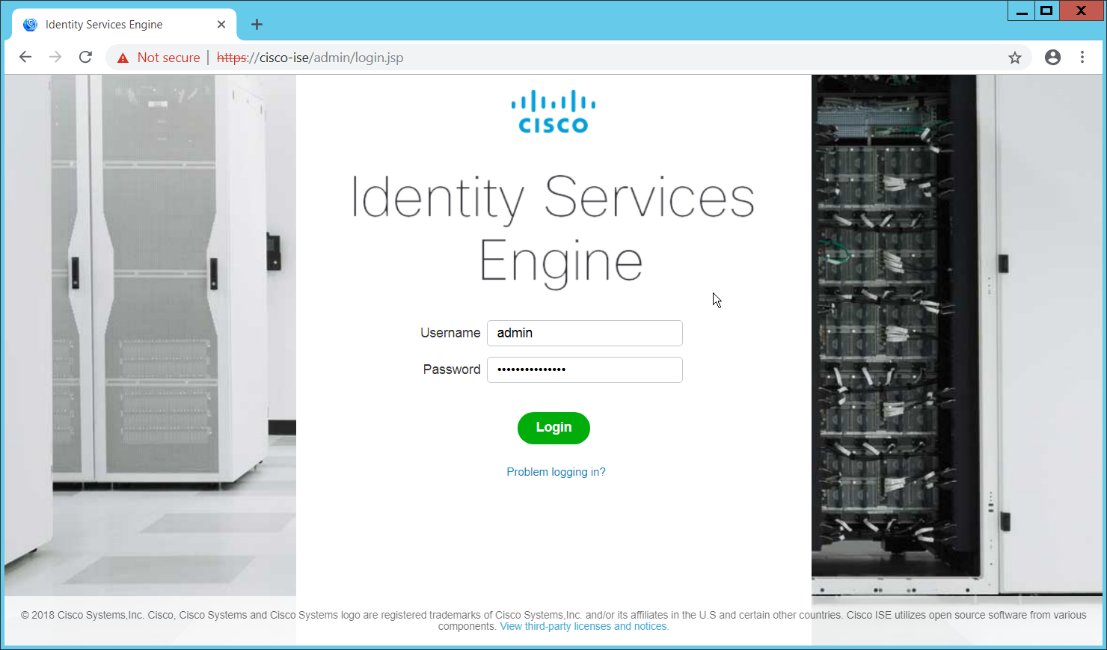
On the top right, use the small Play button to select Visibility Setup.
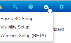
Click Next.
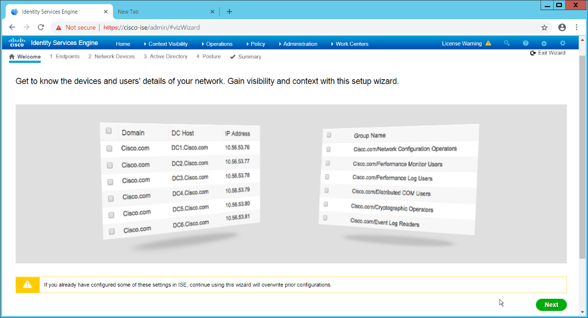
Enter the range of IP addresses to add to ISE’s inventory.
Ensure that Active Scanning is checked.
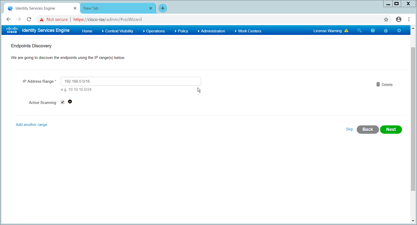
Click Next.
Click the Add Device Manually link.
Enter a name.
Enter the IP address of the network device you configured for SNMP.
Select 1 for SNMP version.
Enter the community string you created.
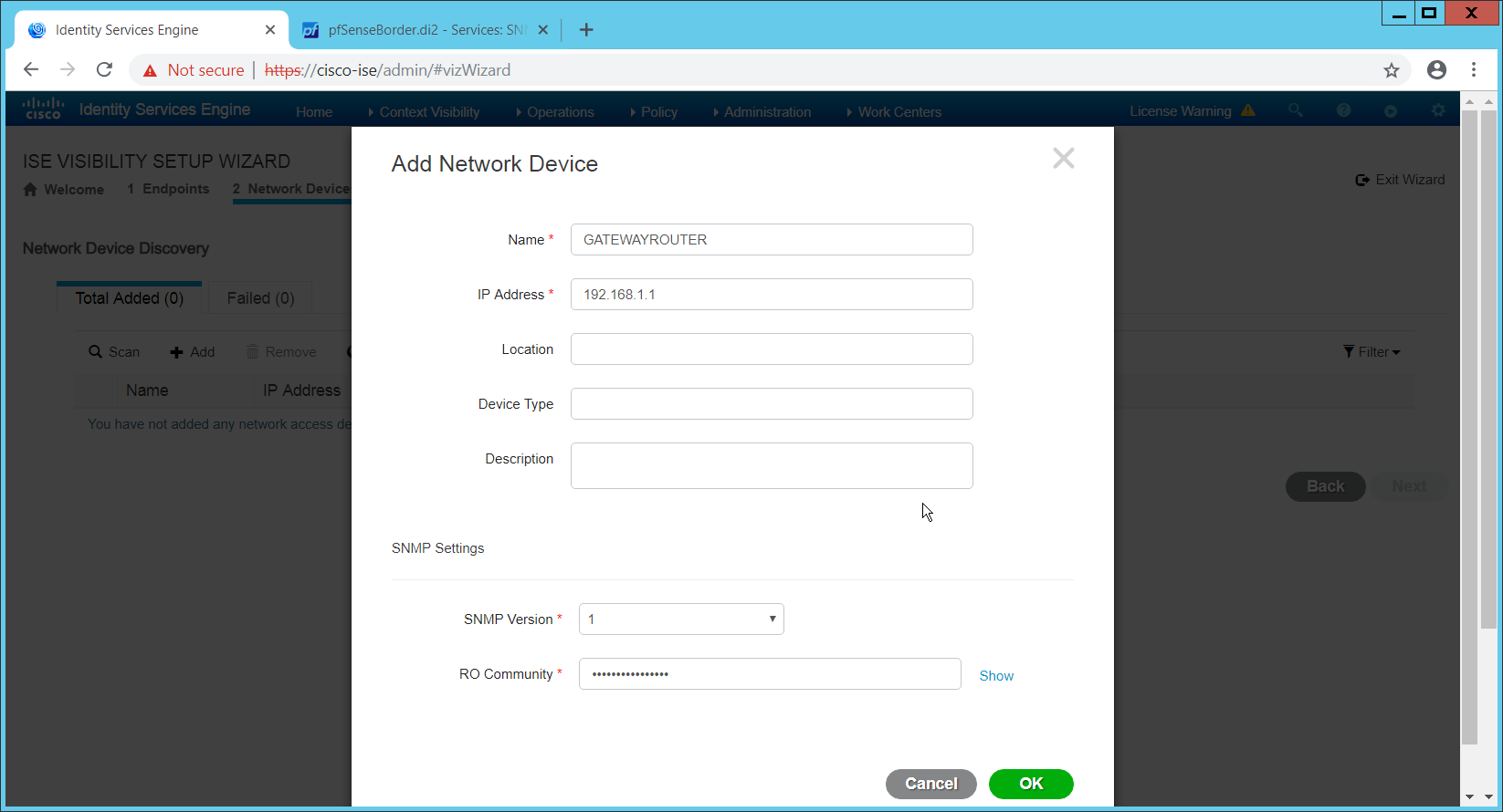
Click OK.
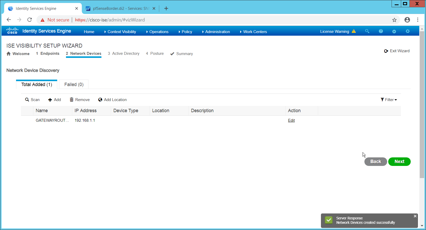
Click Next.
Enter a display name.
Enter the domain name.
Enter the hostname of Cisco ISE.
Enter a username and password.
Click Test Connection to ensure that this works.
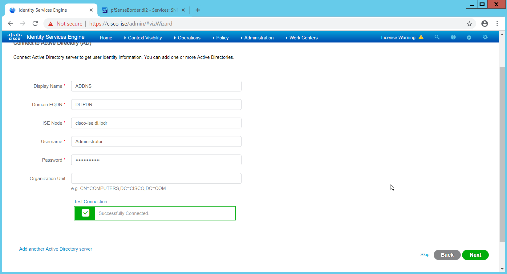
Click Next.
Enter a username and password.
Check the box next to Enable Endpoint Logging.
Check the box next to Include Range.
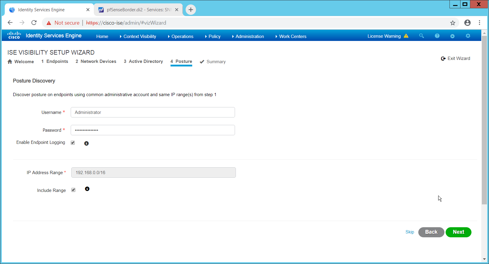
Click Next.
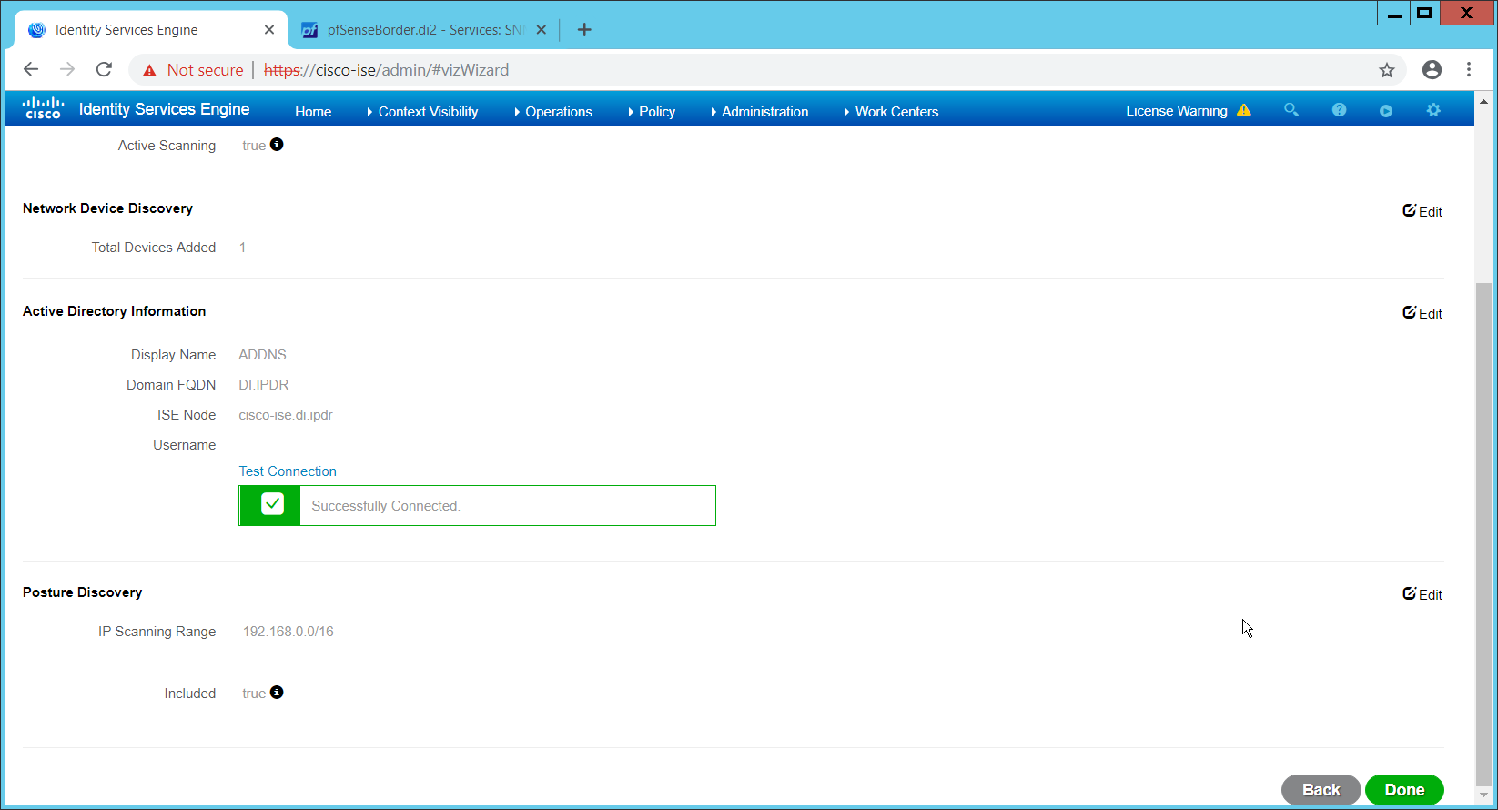
Verify the settings and click Done. (This should begin importing endpoints connected to the network device, and they will be visible on the ISE dashboard.)
2.16.4 Policy Enforcement: Configure Active Directory Integration
Navigate to Administration > Identity Management > External Identity Sources > Active Directory.
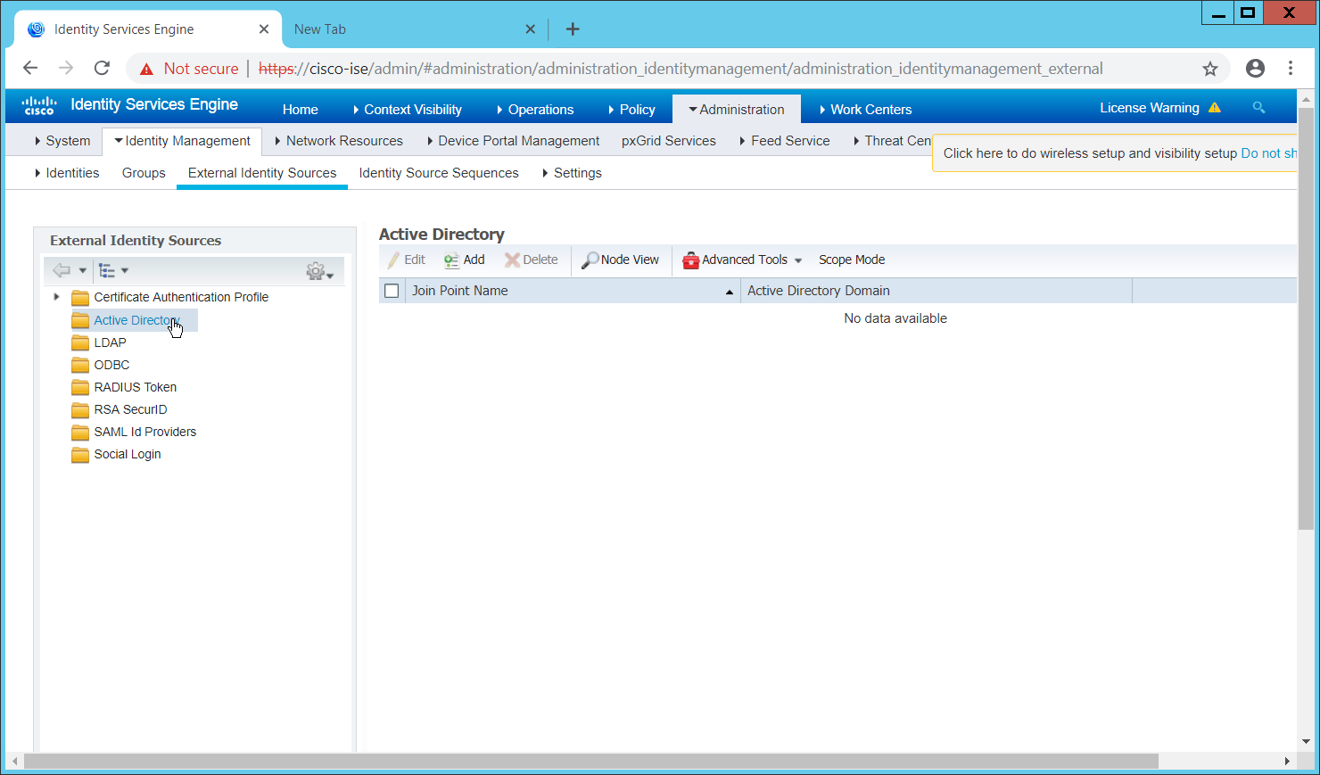
Click Add.
Enter a name.
Enter the domain.
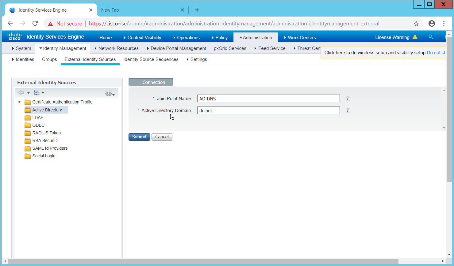
Click Submit.
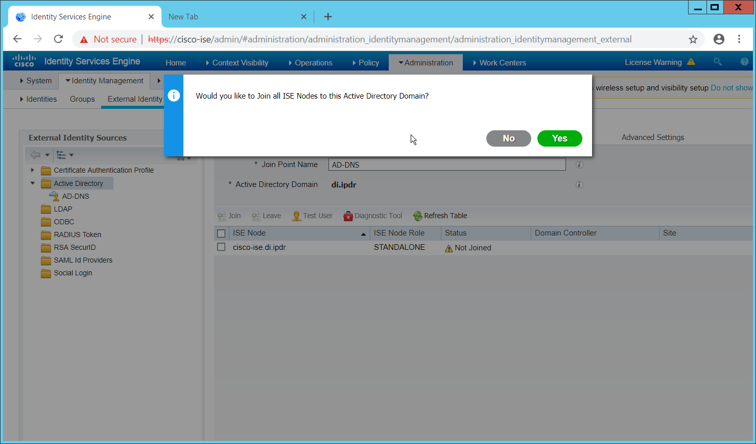
Click Yes.
Enter a username and password to join ISE to the domain.
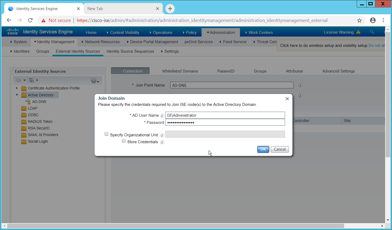
Click OK.
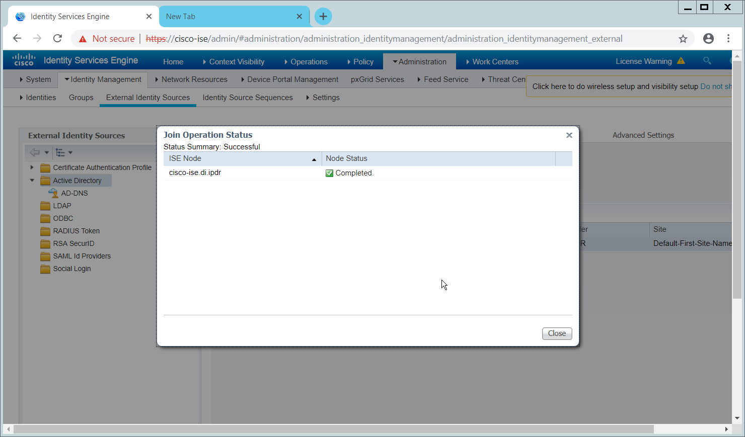
Click Close when the join is finished.
2.16.5 Policy Enforcement: Enable Passive Identity with AD
This configuration allows users to use Active Directory usernames/passwords as authentication for the portal. The web portal will allow clients to download profiling software to ensure that clients have up to date software and can be trusted on the network.
Navigate to Administration > System > Deployment.
Check the box next to ISE.
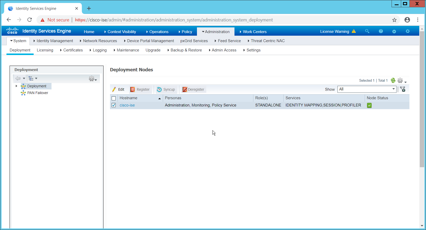
Click Edit.
Check the box next to Enable Passive Identity Service.
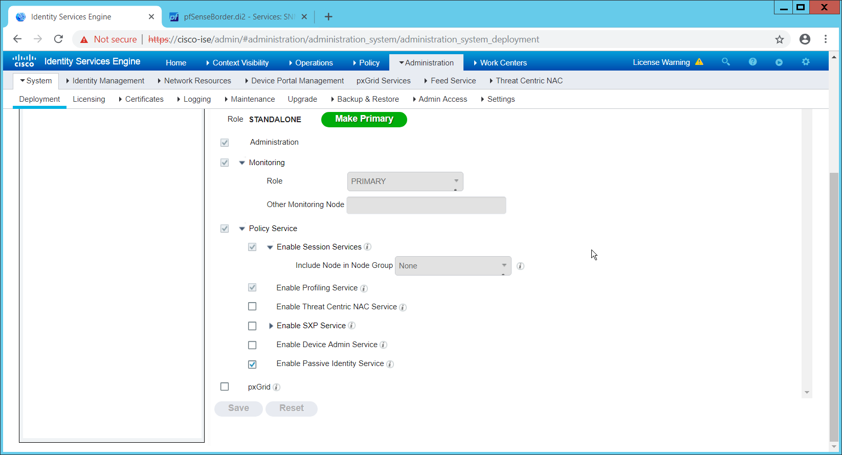
Click Save.
Navigate to Administration > Identity Management > External Identity Sources > Active Directory.
Click the name of the Active Directory machine.
Check the box next to the join point you just created.
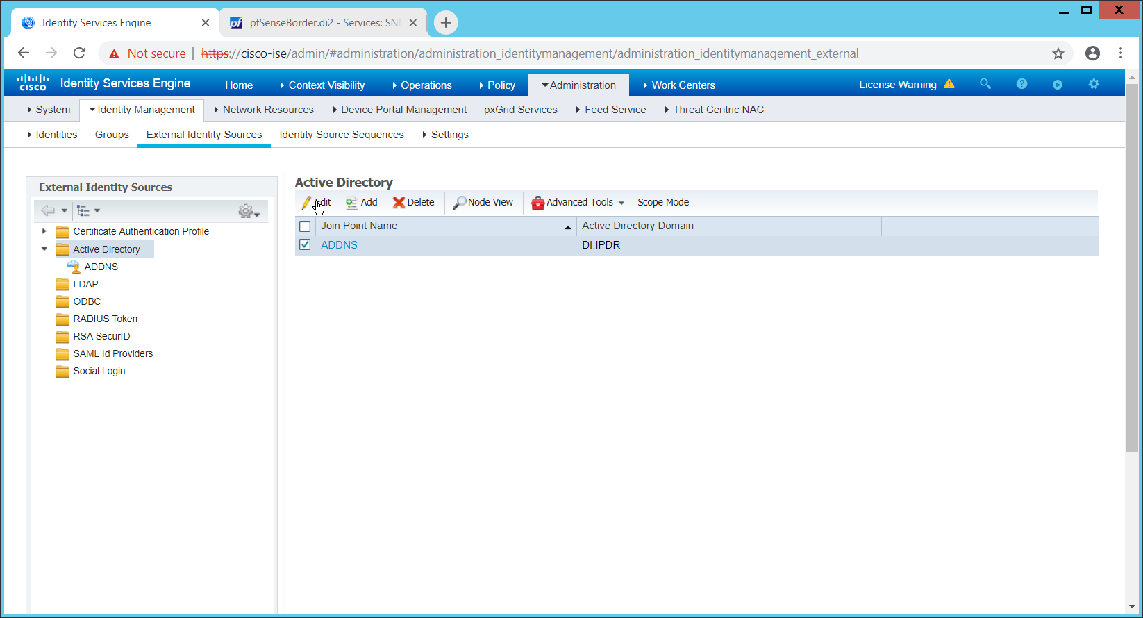
Click Edit.
Click the PassiveID tab.
Click Add DCs if there are no domain controllers listed.
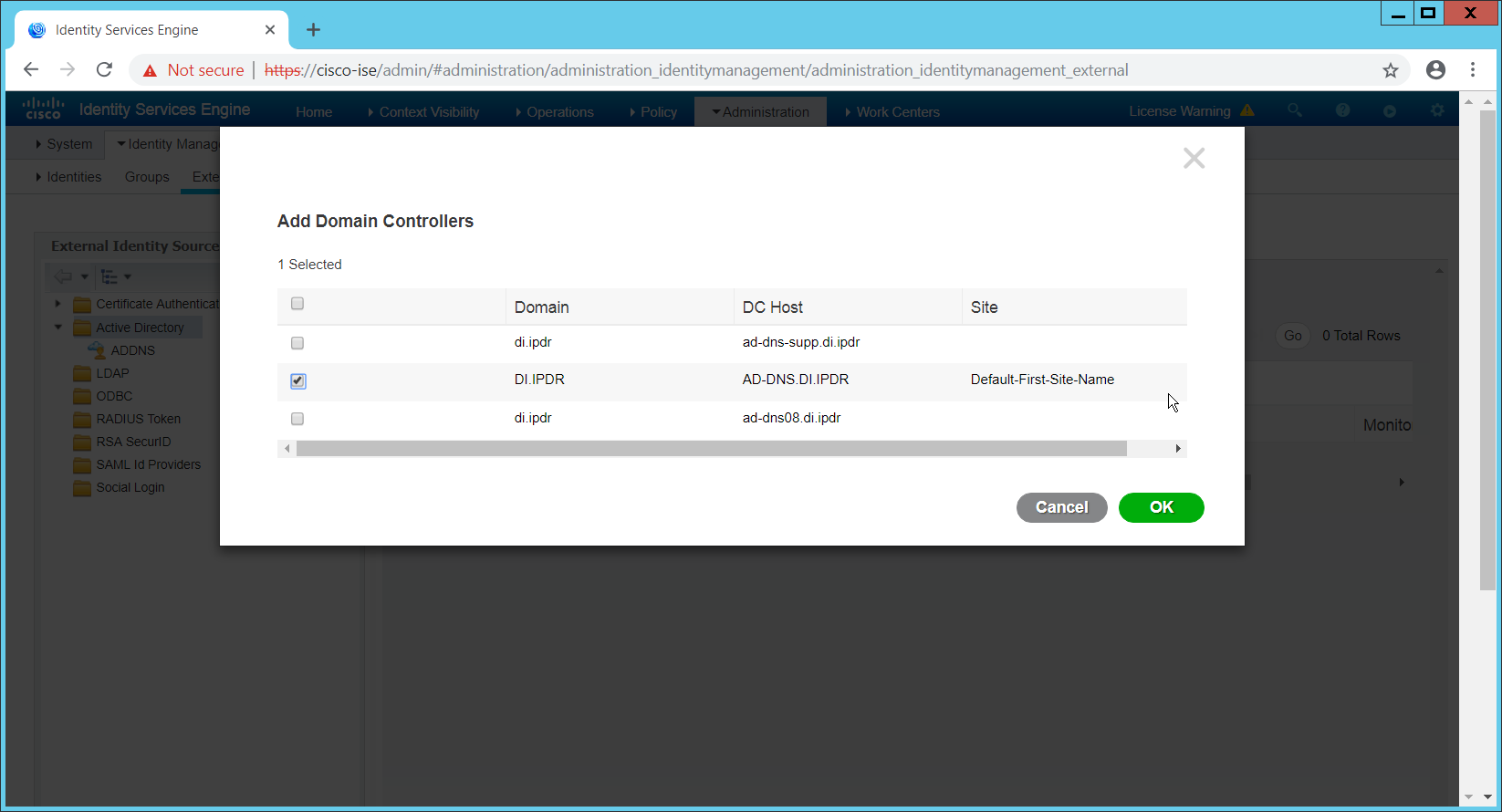
Select the Active Directory domain controller.
Click OK.
Check the box next to the selected domain controller.
Click Edit.
Enter credentials for an administrator account.
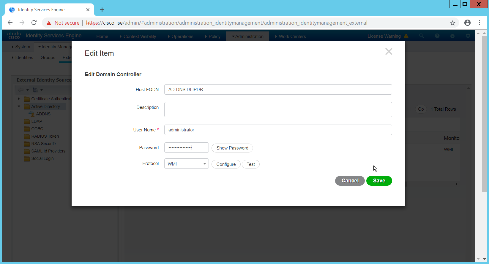
Click Save.
Click Config WMI.
Click OK.
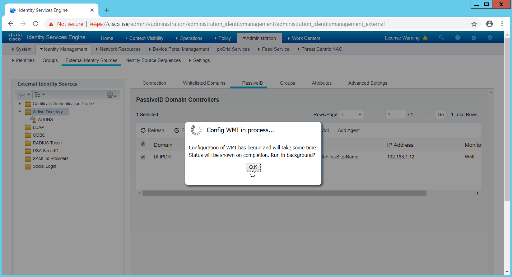
Click OK when this configuration finishes.
Navigate to Administration > System > Settings > Client Provisioning.
Set Enable Automatic Download to Enable.
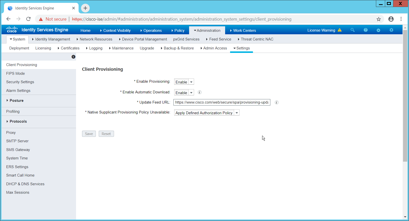
Click Save.
Navigate to Administration > Identity Management > External Identity Sources > Active Directory.
Click the Groups tab.
Click Add > Select Groups from Directory.
Click Retrieve Groups. (This should populate the window with the groups from Active Directory.)
Select them all.
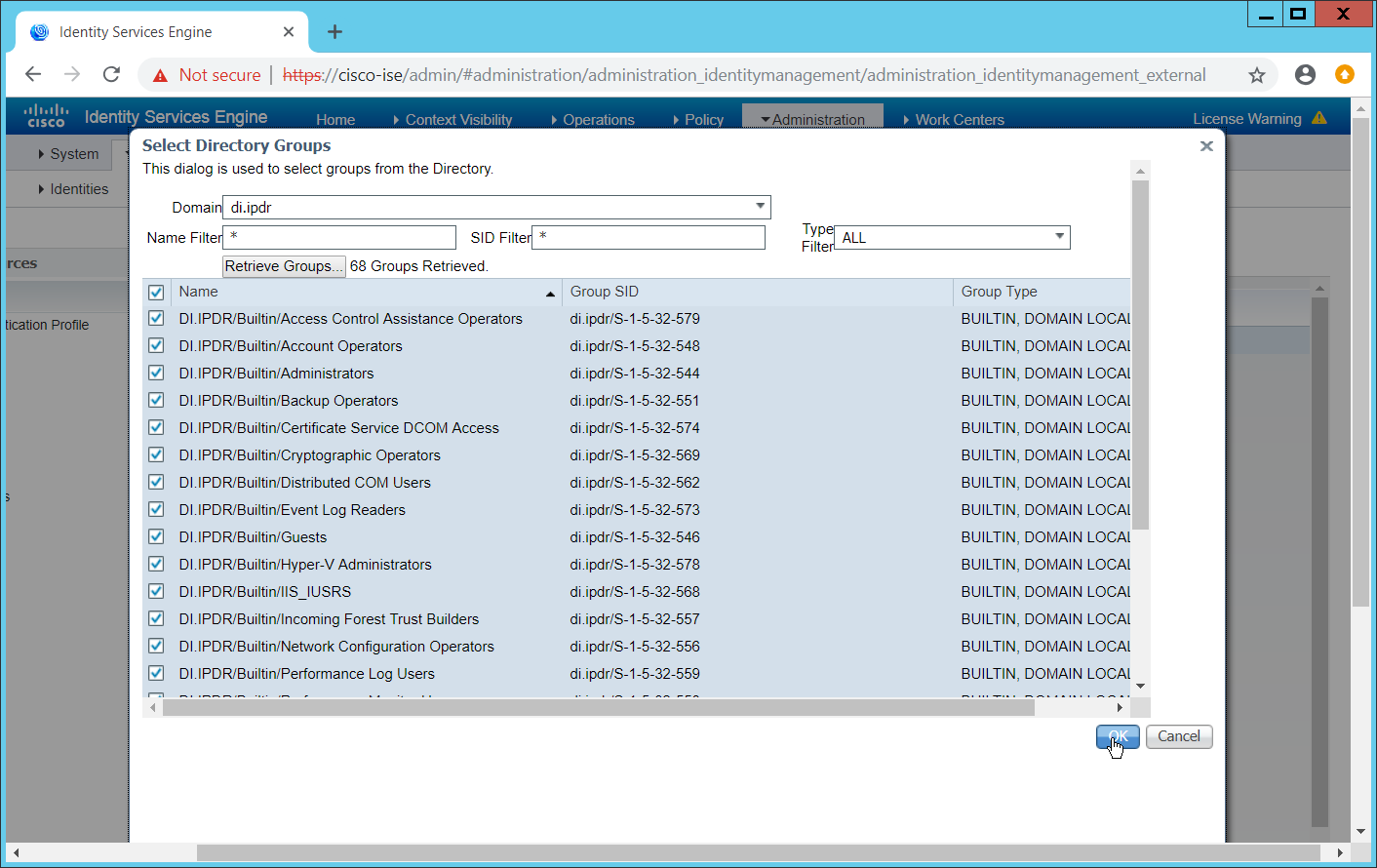
Click OK. (If you add more groups to Active Directory they can be imported in the same way in the future.)
Click the Attributes tab.
Click Add > Select Attributes from Directory.
Enter a username.
Click Retrieve Attributes. (This will populate the window with Active Directory’s available attributes, so they can be used for policy in Cisco ISE.)
Click OK.
Select any desired attributes.
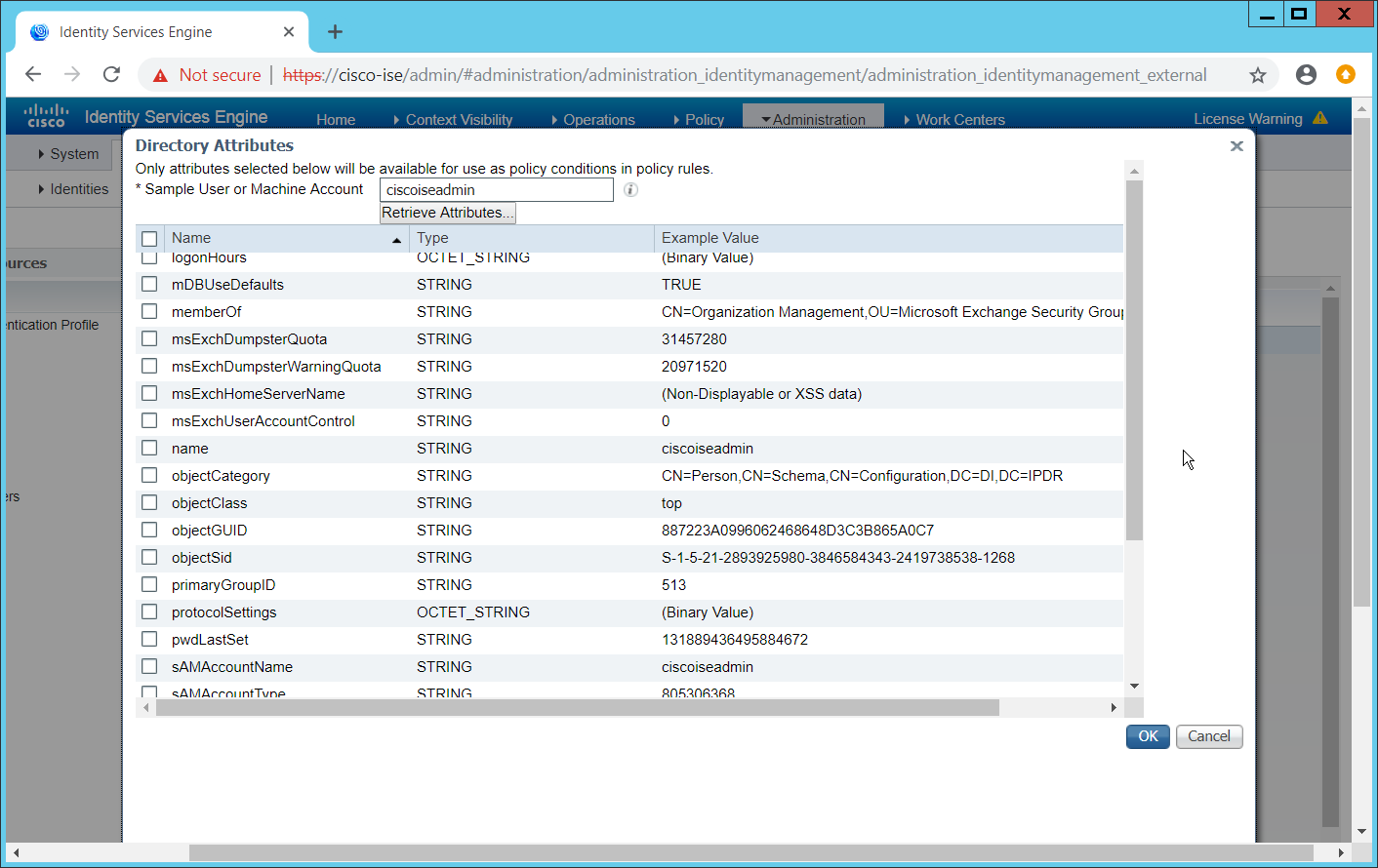
Click OK.
Click Save.
2.16.6 Policy Enforcement: Developing Policy Conditions
Navigate to Policy > Policy Elements > Conditions > Posture.
Expand the Posture section. This will reveal a list of categories for conditions. (Note: These conditions allow you to select or define requirements that endpoints should meet. In typical enterprises, these conditions can be used as requirements to gain network access–however, this strongly depends on the capabilities of your network device.)
As an example, we will require that Cisco AMP be installed on all Windows devices. If you are using a different anti-malware software, locate that instead. Click Anti-Malware Condition.
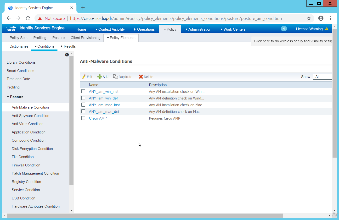
Click Add.
Enter a name.
Enter a description if desired.
Select Windows All for Operating System.
Select Cisco Systems, Inc. for Vendor.
Under Products for Selected Vendor, check the box next to Cisco Advanced Malware Protection with the version number you have installed.
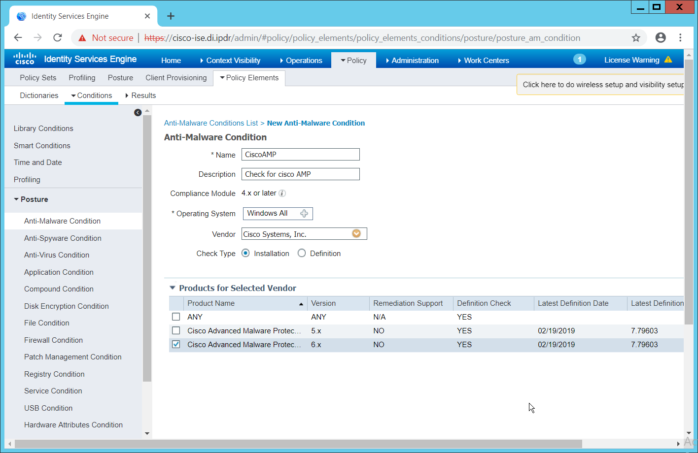
Click Submit.
2.16.7 Policy Enforcement: Developing Policy Results
Navigate to Policy > Policy Elements > Results > Posture > Requirements.
Click one of the black arrows next to the Edit link, and select Insert New Requirement.
Enter a name.
Select Windows All for Operating Systems.
Select 4.x or later for Compliance Module.
Select Temporal Agent for Posture.
Select User Defined Conditions > Anti-Malware Condition > Cisco AMP (substitute Cisco AMP with the name of the condition you just created).
Select Message Text Only for the Remediation Action. (Other remediation actions can be defined by going to Policy > Policy Elements > Results > Posture > Remediation Actions, but there is not an option for Cisco AMP to be installed, so we leave the default for now.)
Enter a Message to inform the user that they must install Cisco AMP.
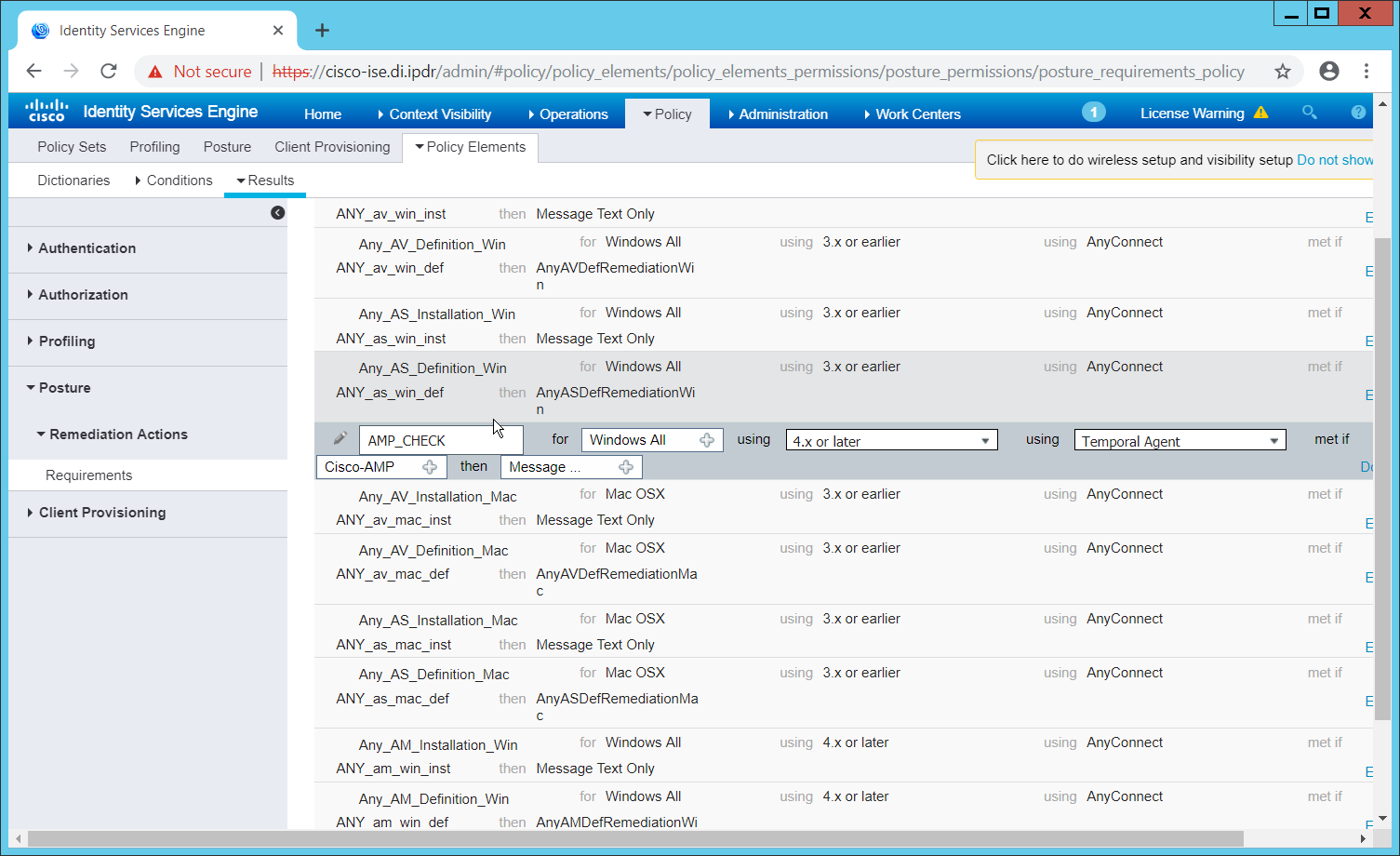
Click Save.
2.16.8 Policy Enforcement: Enforcing a Requirement in Policy
Navigate to Policy > Posture.
Click one of the black arrows next to the Edit link, and select Insert New Policy.
Enter a name.
Select Windows All for Operating Systems.
Select 4.x or later for Compliance Module.
Select Temporal Agent for Posture Type.
Select Cisco AMP (substitute Cisco AMP with the name of the requirement you just created).
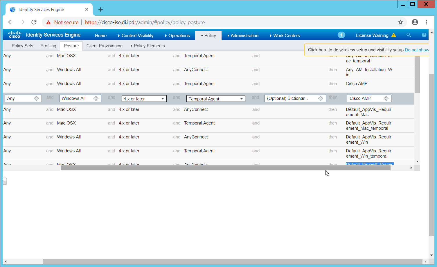
Click Done.
Ensure that the green checkboxes next to the rules you wish to apply are the only checkboxes enabled, as anything enabled will be enforced.
2.16.9 Policy Enforcement: Configuring a Web Portal
Navigate to Administration > Device Portal Management > Client Provisioning.
Select the Client Provisioning Portal (default).
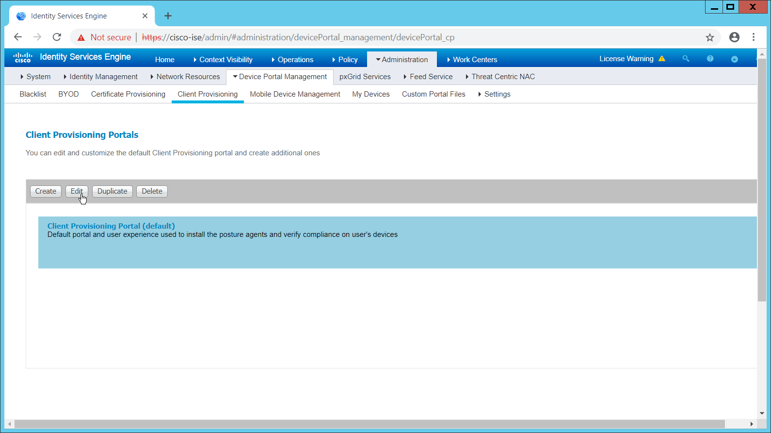
Click Edit.
Under Portal Settings, go to Configure authorized groups and select the groups that should require a Cisco ISE client.
Enter a domain name for FQDN, and add it to your DNS.
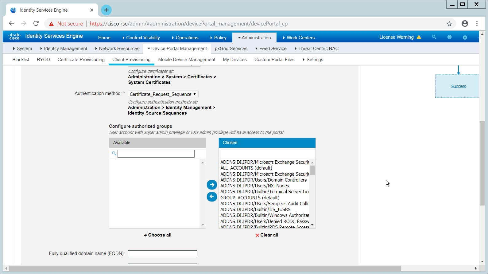
Click Save.
2.16.10 Configuring RADIUS with Your Network Device
Cisco ISE requires a Remote Authentication Dial-In User Service (RADIUS) session for posture to function. Posture refers to ISE’s ability to check that a machine complies with a specified policy, which may be based on the operating system (OS) and may contain requirements such as installation of certain security applications or the presence of configuration files. Machines that are not in compliance can be kept separated from the network. The process for setting this up varies widely among machines, but the overall requirements have commonalities among systems.
The Network Device (i.e., the router or switch) must support RADIUS functions, specifically Authentication, Authorization, and Accounting. Furthermore, it must also support CoA, which is Change of Authorization. To configure this, you must configure your network device to use Cisco ISE as a RADIUS server. What this means is that your network device will forward authentication requests to Cisco ISE, and Cisco ISE will respond with an “accept” or “reject.”
The Network Device must support some form of 802.1x. Note that this is not supported on certain routers, even if RADIUS is supported. 802.1x is a mechanism for authenticating the end workstation to the network device, potentially over wireless or through Ethernet.
This can take various forms, such as a captive web portal, MAC address authentication, or user authentication. A captive web portal, if the device supports it, may be ideal for configuration without the correct hardware.
There are also many switches that provide direct 802.1x username/password authentication. Note that if you choose to use this mechanism, a client is still required, and it will not be in the web browser. Windows has a built-in 802.1x client, which can be configured on network adapters under the Authentication tab. To enable it, you must first start the service Wired AutoConfig, and then the Authentication tab will become available for configuration.
Whatever form of 802.1x is chosen, the request for authentication must be forwarded to Cisco ISE. Cisco ISE will process the request for authentication.
The two steps above detail the authentication phase. Once authenticated, the network device must redirect the user to the client provisioning portal (or to a guest portal), depending on the setup. The URL for this can be acquired from the active Authorization Profile in ISE.
The user will then authenticate to the Guest Portal or Client Provisioning Portal (depending on your setup). The portal will prompt the user to download an executable, which will run posture.
The executable will first check for the existence of a RADIUS session in Cisco ISE for the user who downloaded the executable. It will primarily check the MAC address that visited the ISE web portal against the MAC addresses of existing sessions. If and only if a session exists, it will run posture based on the policy you set up. You can verify that a session exists by navigating to Operations > RADIUS > Live Sessions.
2.16.11 Configuring an Authentication Policy
Navigate to Policy > Policy Elements > Results > Authentication > Allowed Protocols.
Select the Default Network Access protocol or create your own.
Ensure that any protocols that need to be supported for your network setup are allowed. In particular, if using 802.1x, it is likely that you should check the box next to Allow MS-CHAPv2.
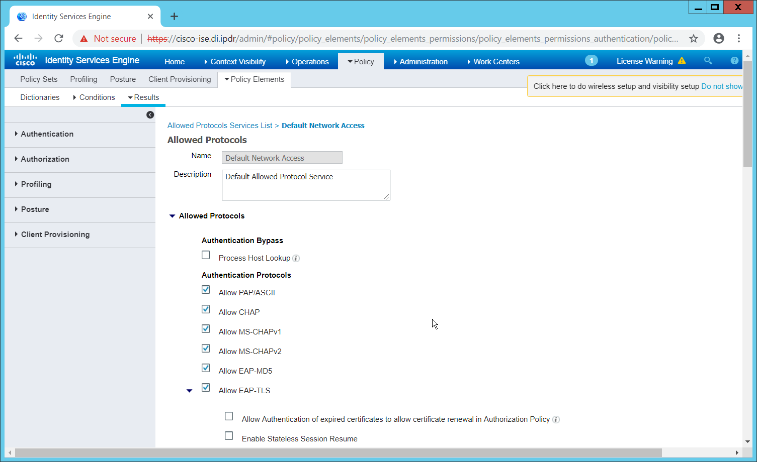
Click Save.
Navigate to Policy > Policy Sets.
Select the default policy.
Ensure that the Allowed Protocol selection matches the allowed protocol you just created/edited.
Expand the Authentication Policy section, and select the ID stores from which to authenticate users. For example, if you set up an Active Directory integration, it may be desirable to authenticate users from there.
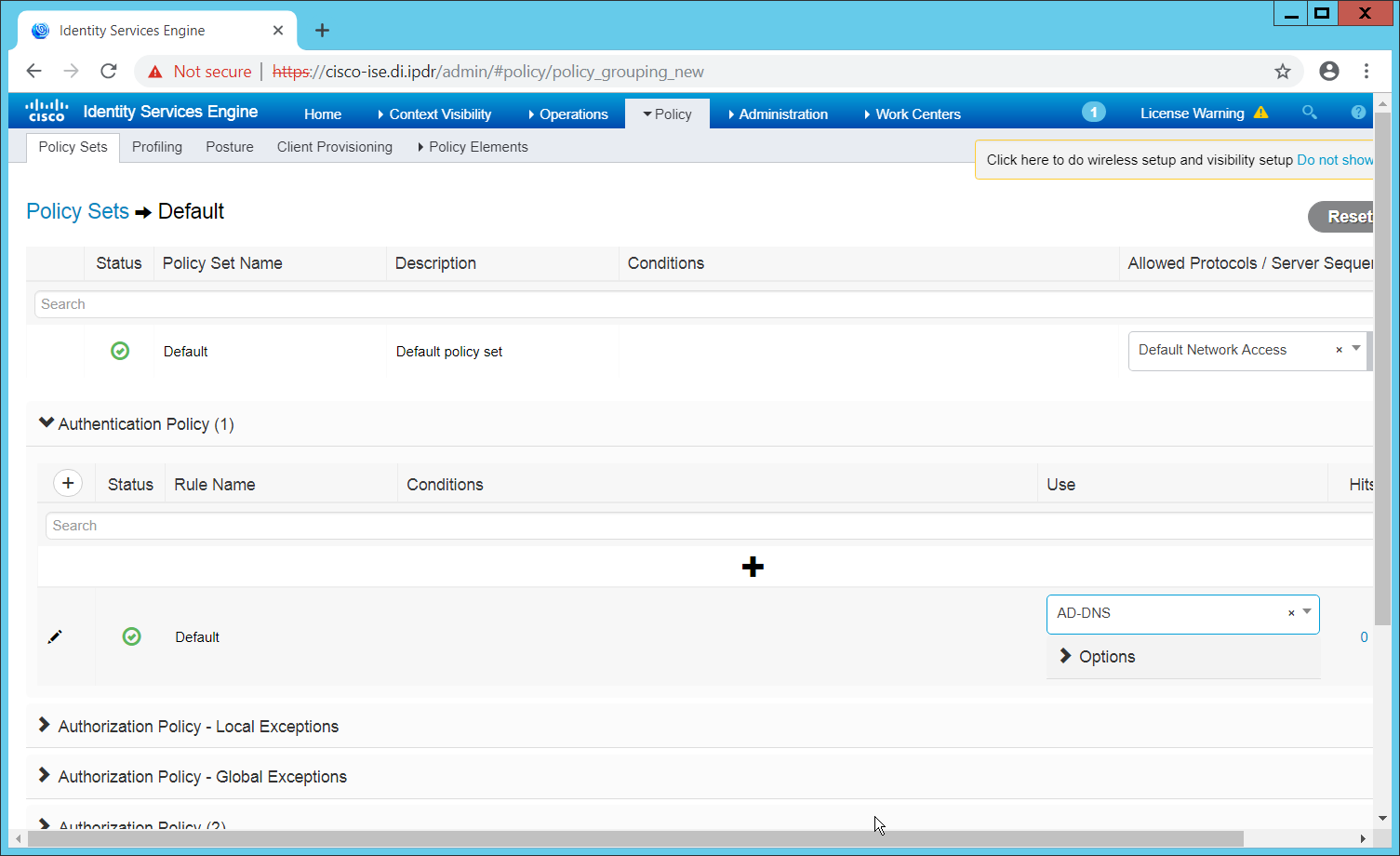
Click Save.
2.16.12 Configuring an Authorization Policy
The Authorization Profile is likely dependent on your network device, but it is possible that the Cisco_Temporal_Onboard profile will work even for non-Cisco devices. You can edit the authorization policy by navigating to Policy > Policy Elements > Results > Authorization > Authorization Profiles.
The temporal onboard profile will attempt to redirect the user to a client-provisioning portal. This redirection will most likely happen only automatically on compatible Cisco network devices. If another device is used, the device may need to manually redirect the user to the client-provisioning portal after authentication. (We accomplished this in pfSense for our build by using a “post-authentication redirection” feature in the Captive Portal.)
Once you are finished configuring the Authorization Profile, navigate to Policy > Policy Sets.
Select the default policy.
Expand the Authorization Policy section.
Note that you can configure this for as many groups and conditions as desired, potentially specifying different authorization profiles for various user groups or levels of authentication, including unauthenticated access. Under Results > Profiles, you can select the authorization profiles you configured.
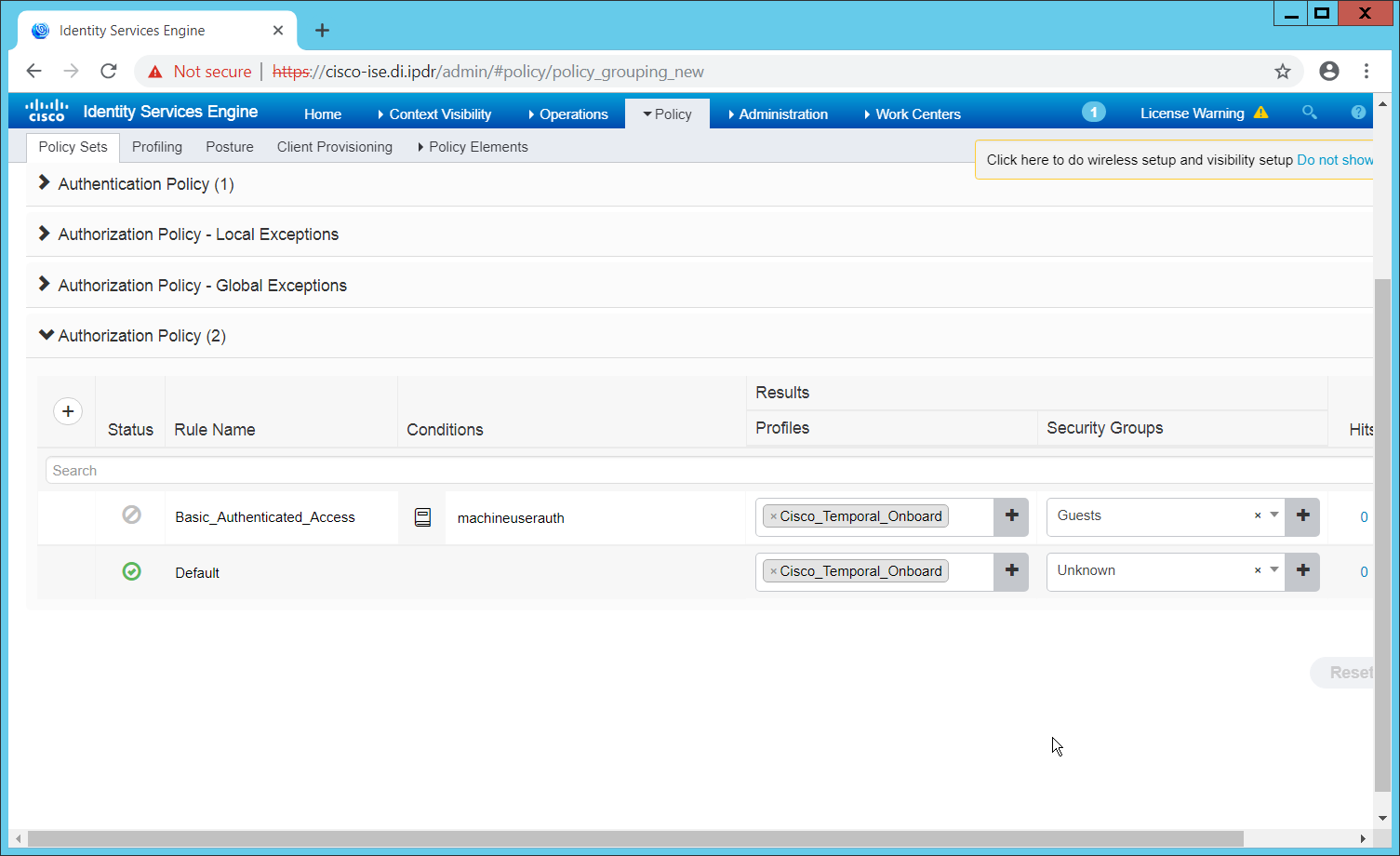
Click Save.
2.17 Tripwire IP360
This section details installation and configuration for Tripwire IP360.
2.17.1 Installation
Move or copy the Tripwire IP360 Virtual Machine into your virtual environment; start Virtual Machine and observe its successful start-up.
Log in using default admin credentials.
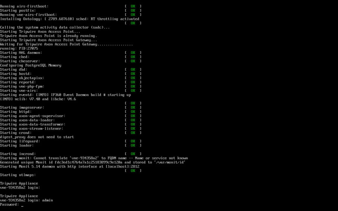
When prompted after initial login, set a new password and record it in a safe location.
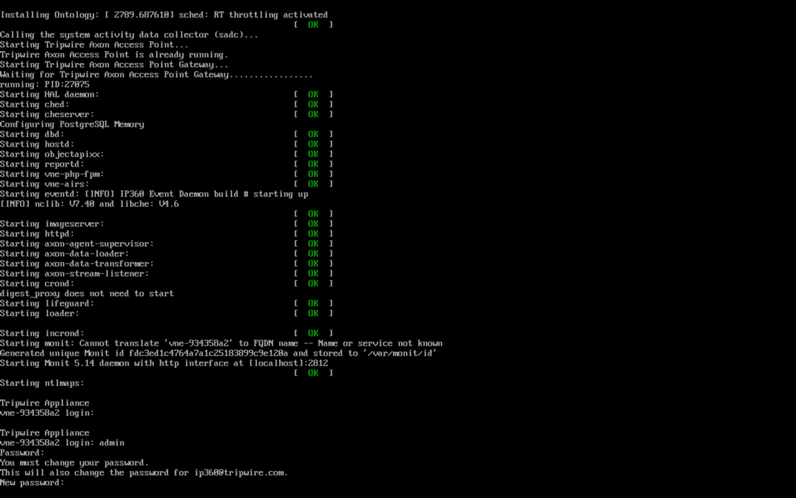
Use the command system hostname update <hostname> to update the system’s hostname in accordance with your environment’s naming scheme.
Use command network interface update <interface> <IP>/<Broadcast IP> to update network interface information in accordance with your environment’s network.
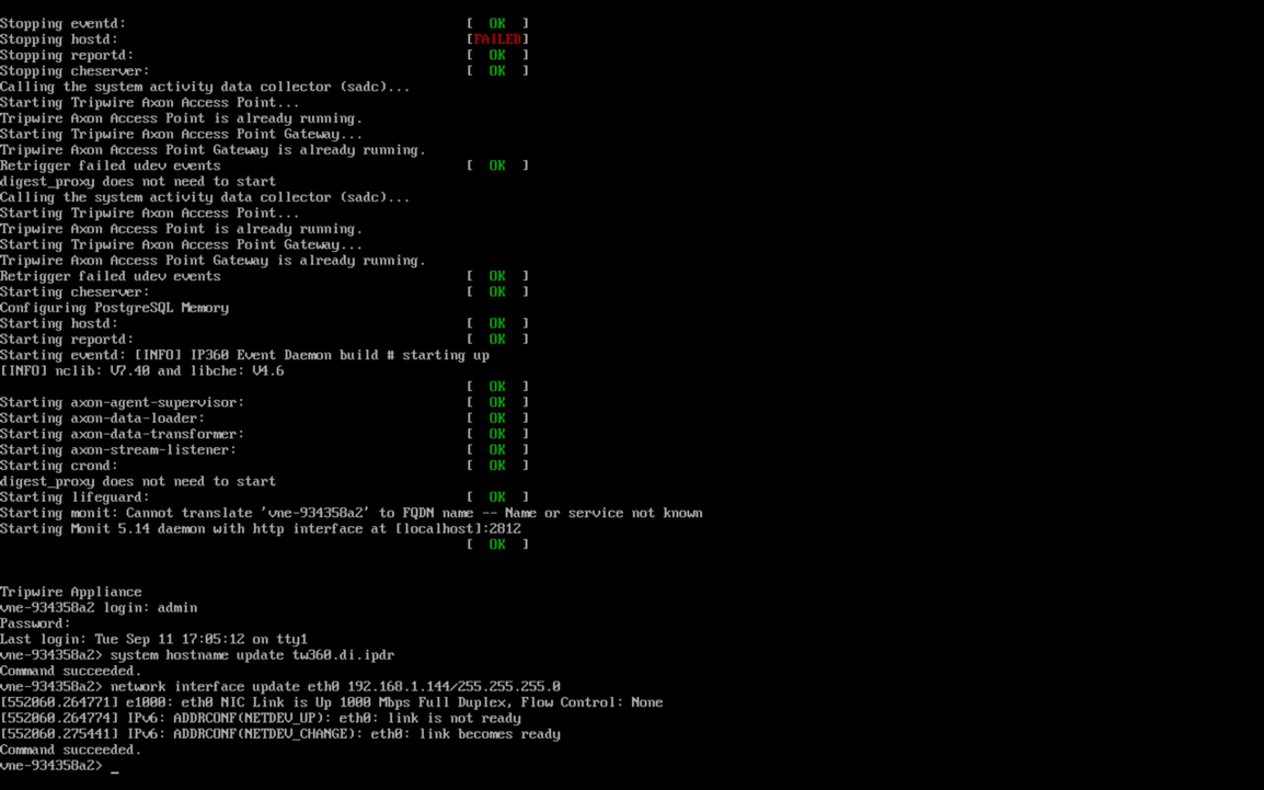
Use command network route_default create <gateway> to update the system’s default gateway information in accordance with your environment’s network.
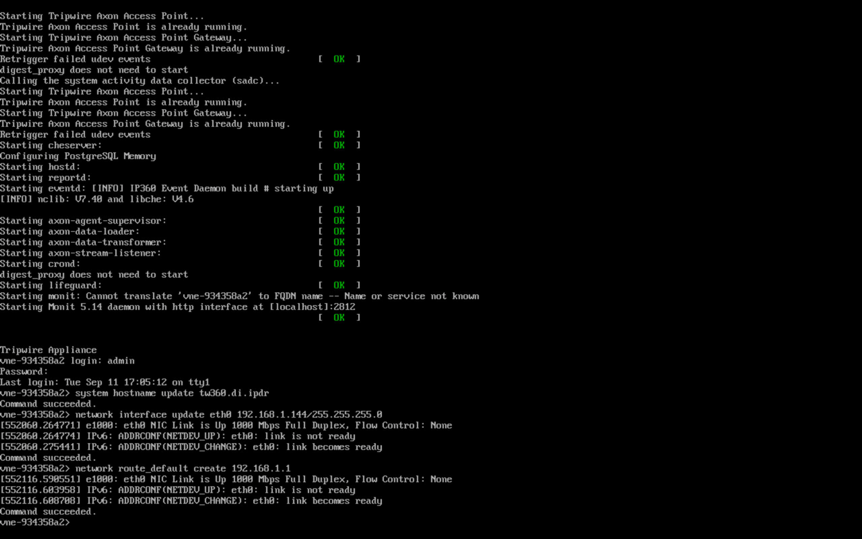
Use command system nameserver create <nameserver IP> to set up the DNS server.
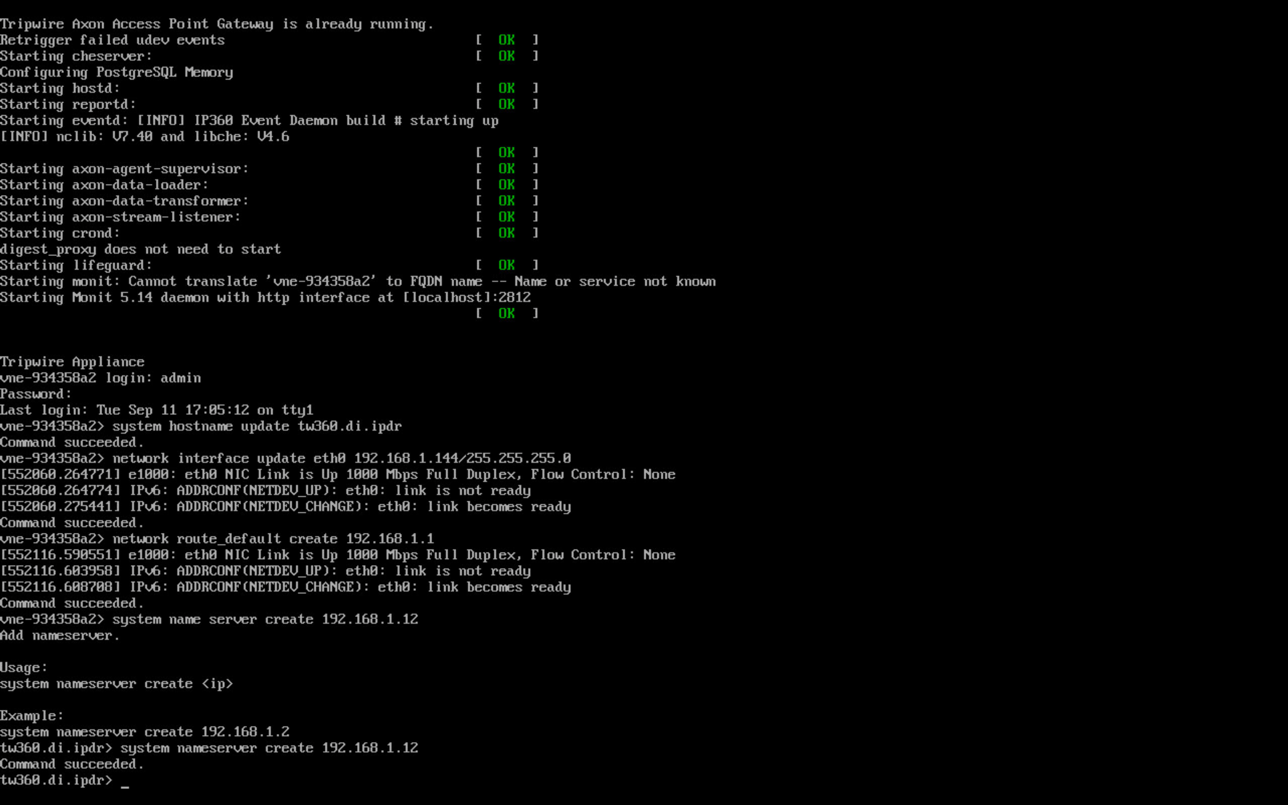
2.17.2 Web Portal
From a web browser that can access the newly installed machine’s IP address, navigate to the IP address and log in using the updated credentials from the setup process.
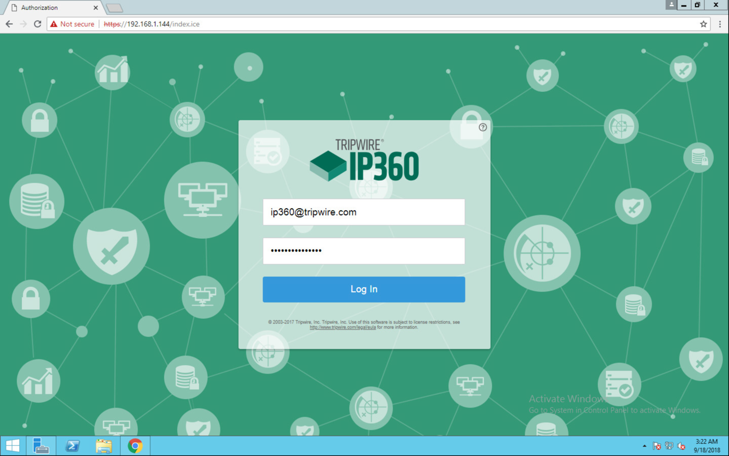
Check the box next to I accept the above User License Agreement.
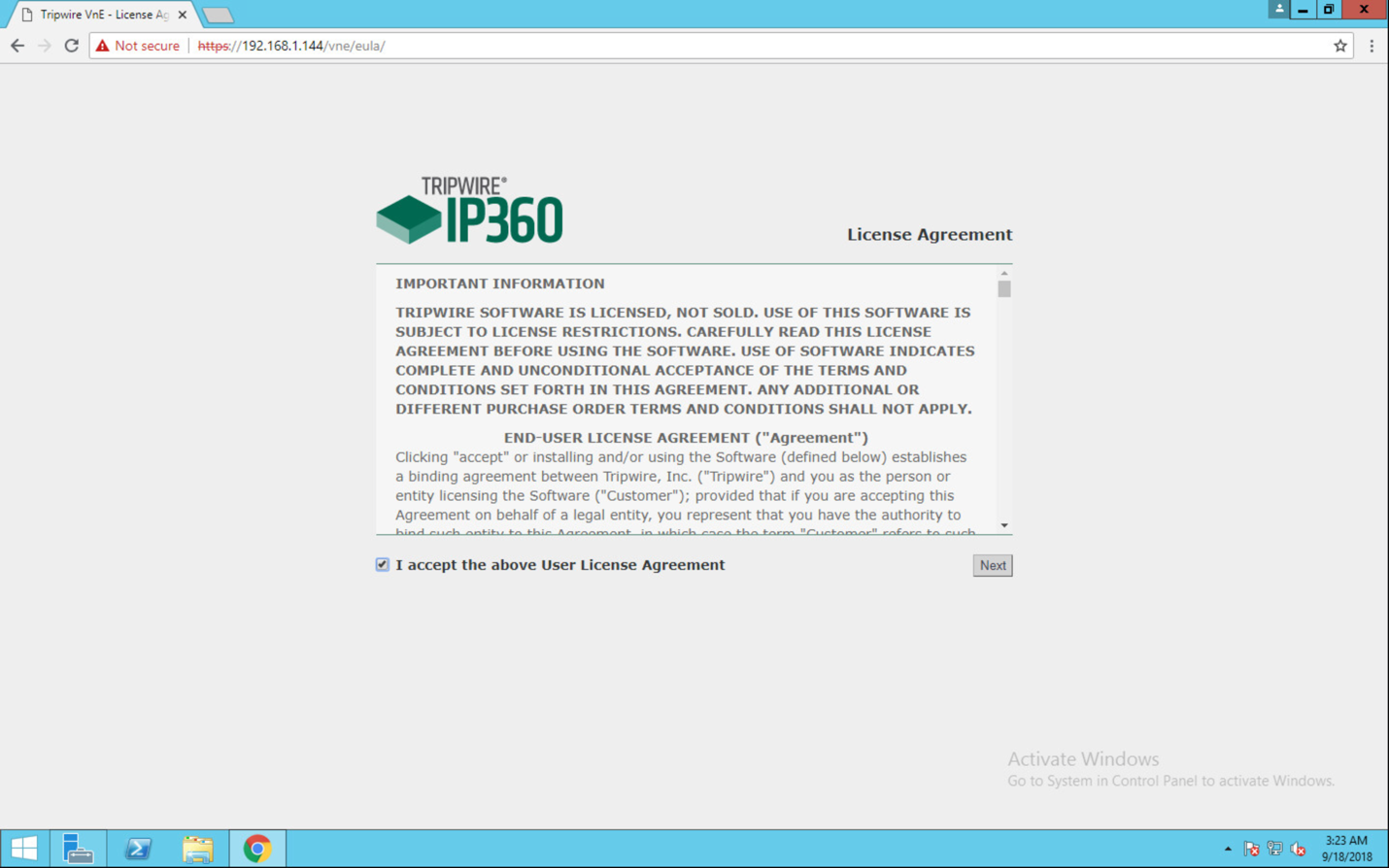
Click Next.
Browse to location of downloaded license file.
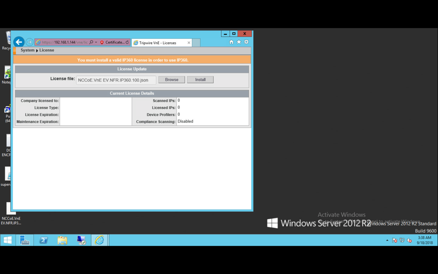
Click Install.
Tripwire IP360 should now be installed and running.
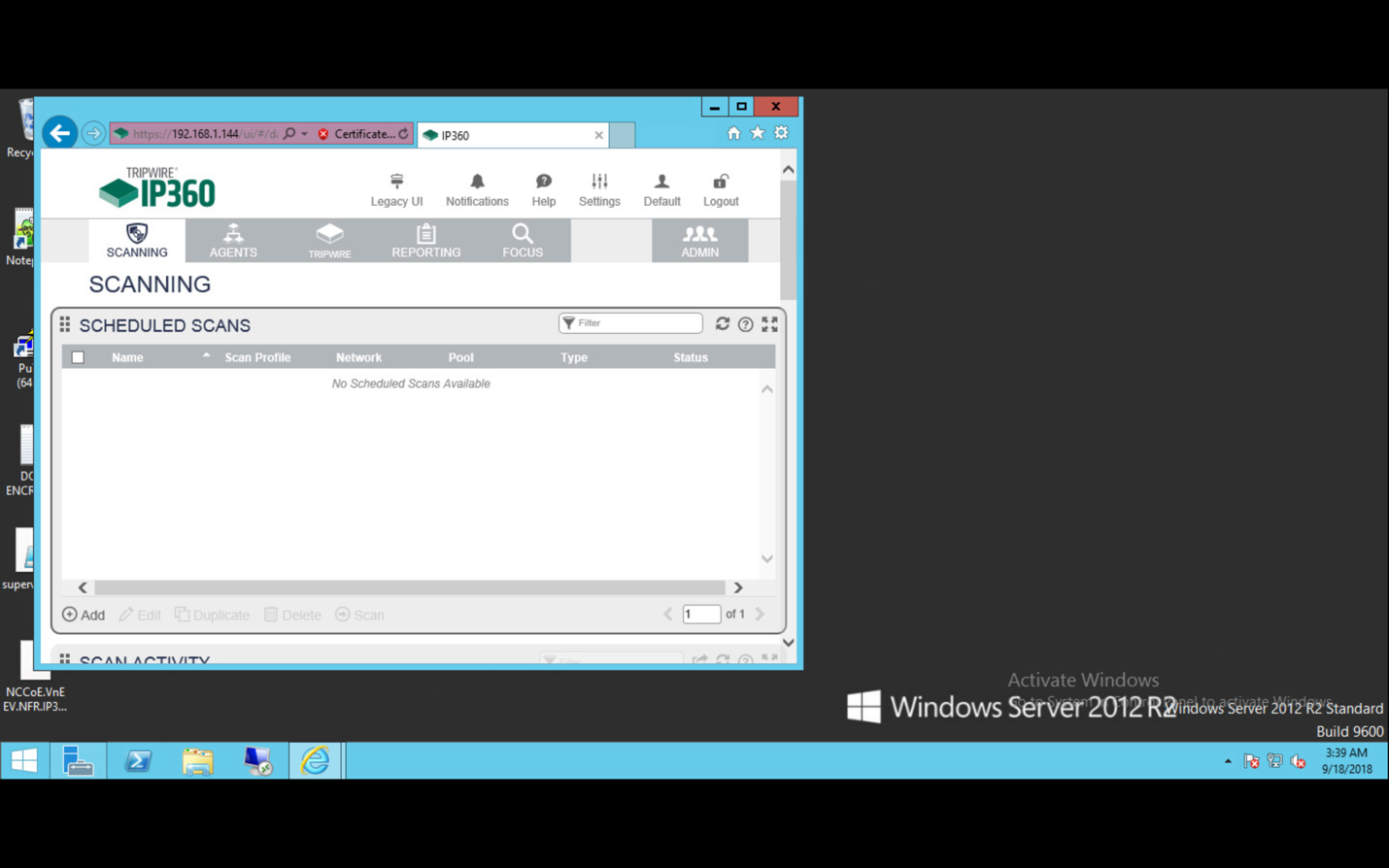
2.17.3 Scanning
This section details instructions for using Tripwire IP360 to run a scan on enterprise systems. The specific details of the scan will vary based on each enterprise’s security needs.
Navigate to the web interface and log in.
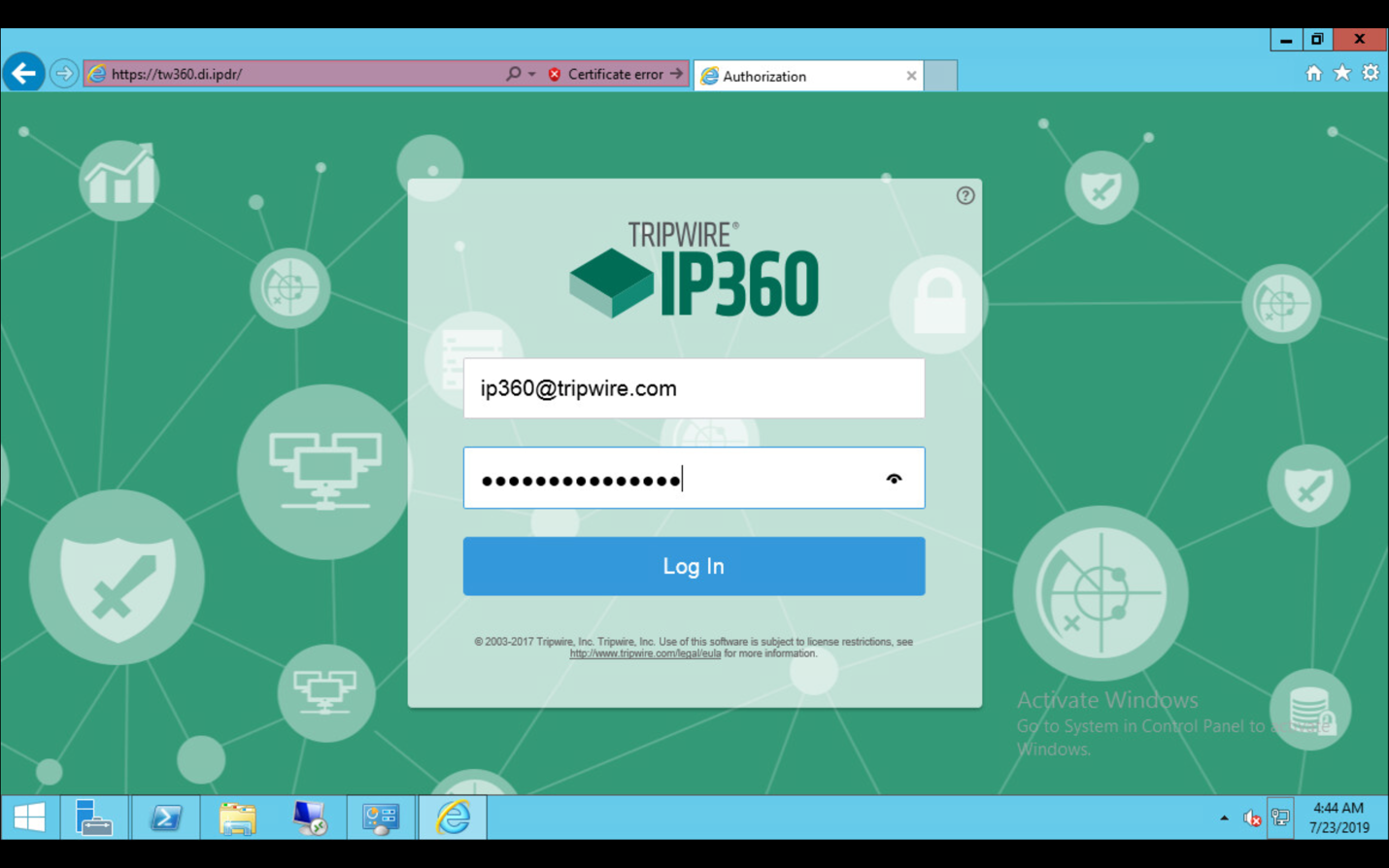
Navigate to the Scanning tab.
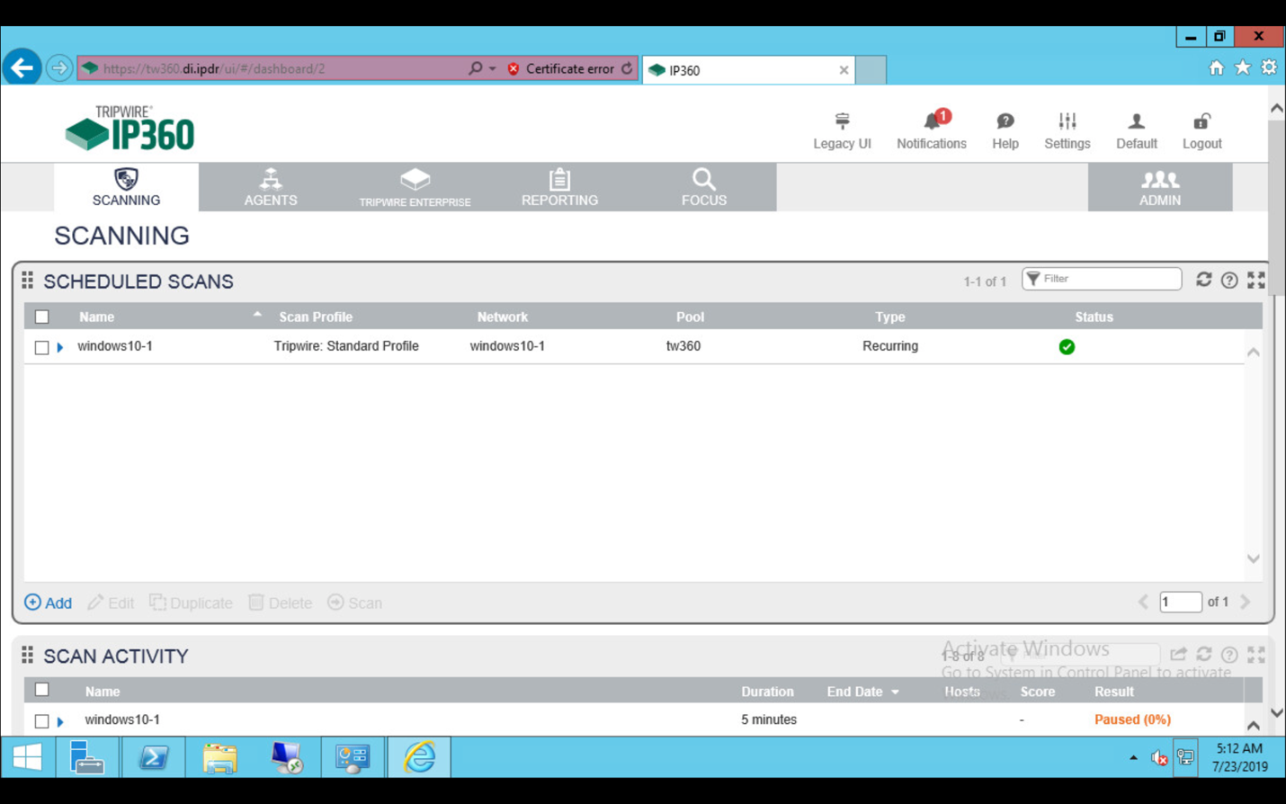
Click Add.
Complete the information regarding the new scan according to the preferences of your organization.
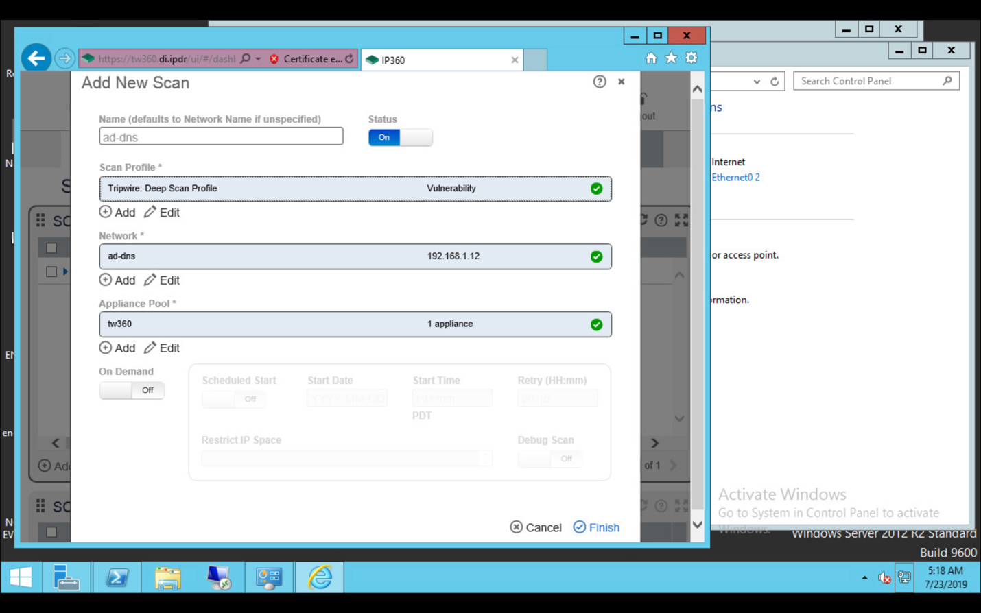
Observe successful scan activity.
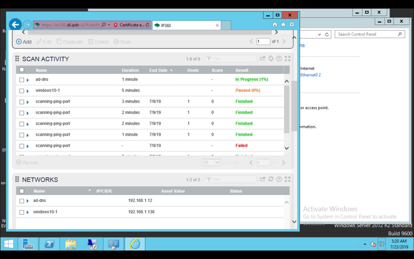
2.18 Integration: Tripwire Log Center and Tripwire Enterprise
Create a user account in Tripwire Log Center by logging into Tripwire Log Center Console.
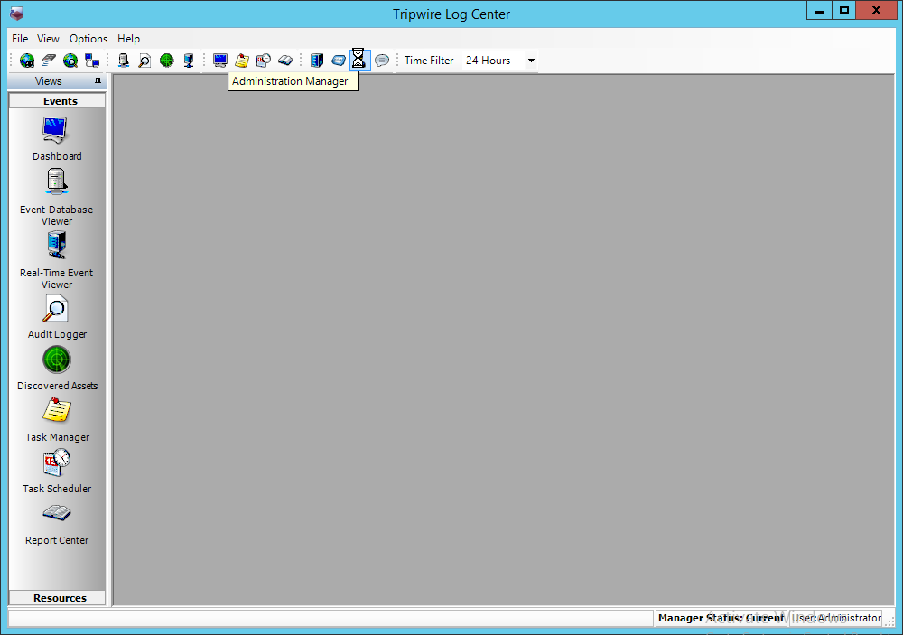
Click the Administration Manager button.
Click User Accounts.
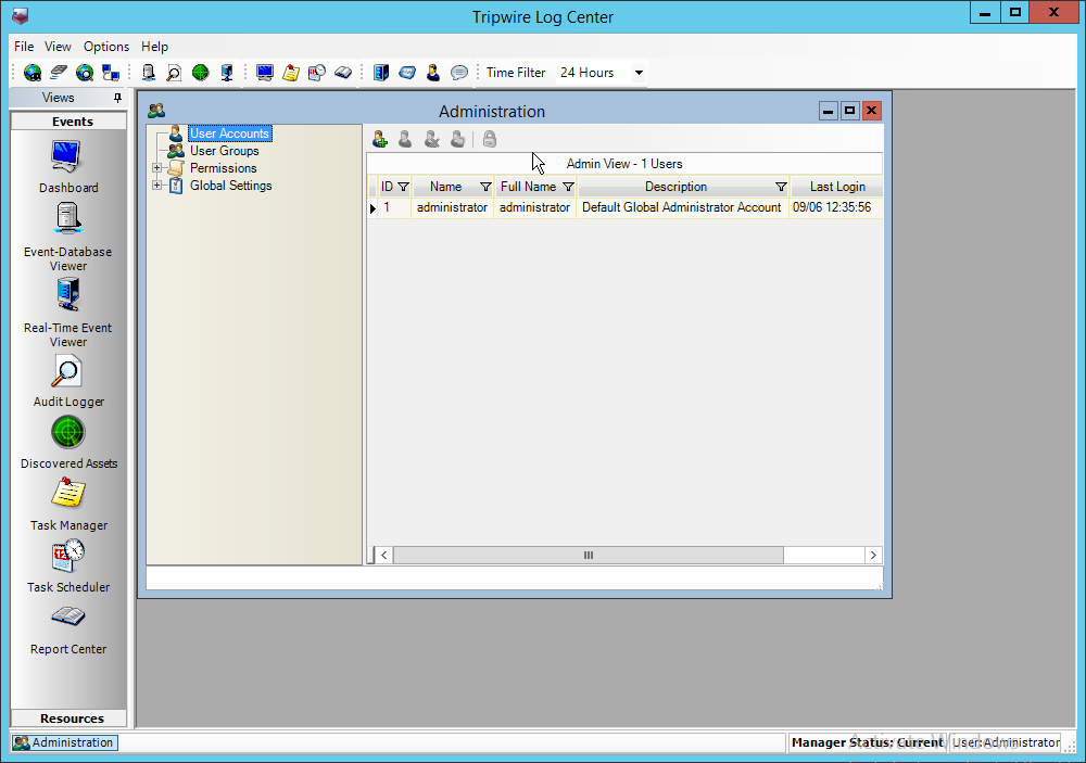
Click the Add button.
Enter the details of the user.
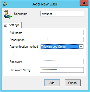
Click Add.
Double-click the user account.
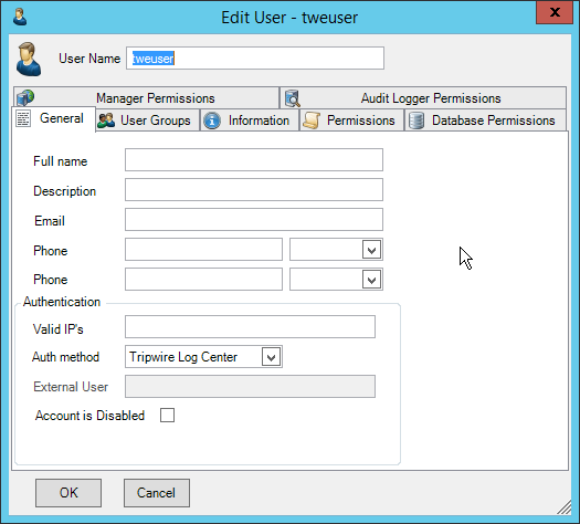
Click the Permissions tab.
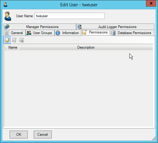
Click Edit list of permissions.
Select Databases.
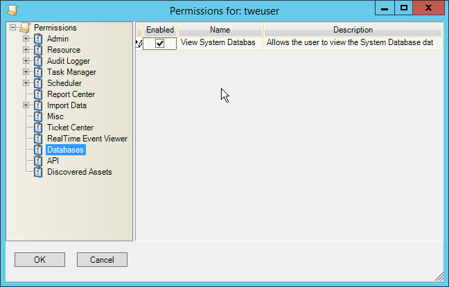
Check the box next to View System Database.
Select API.
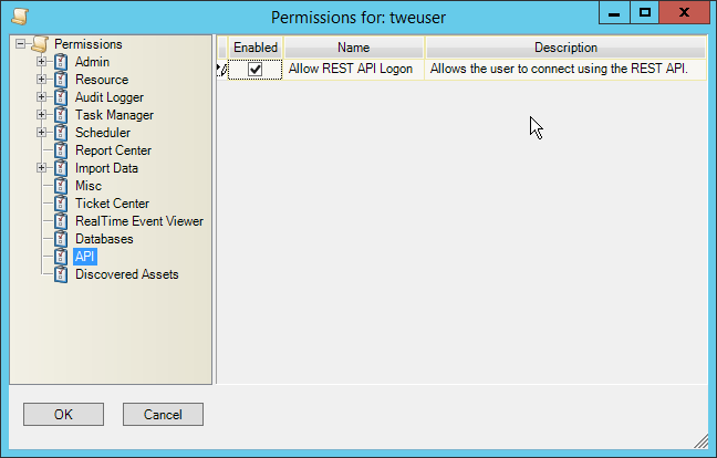
Check the box next to Allow REST API Logon.
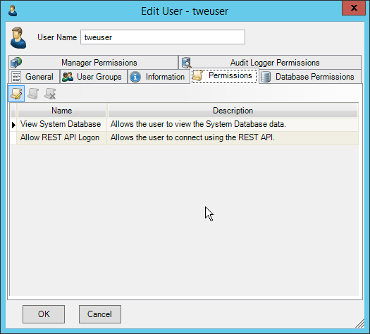
Click OK.
Click OK.
Log in to the Tripwire Enterprise web console.
Click Settings.
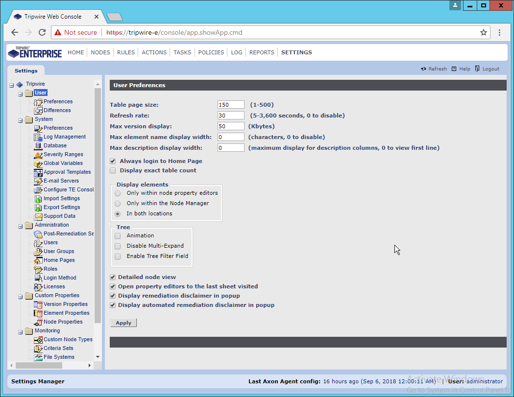
Go to System > Log Management.
Check the box next to Forward TE log messages to syslog.
Enter the hostname and port of the Tripwire Log Center server. The default port is 1468.
Check the box next to Allow TE to use information from Tripwire Log Center.
Enter the service address like this: https://arcsight-cons.di.ipdr:8091/tlc. Replace the hostname with the hostname of your Tripwire Log Center server.
Enter the account information of the account just created for Tripwire Log Center.
You can use Test Connection to verify that the connection is working.
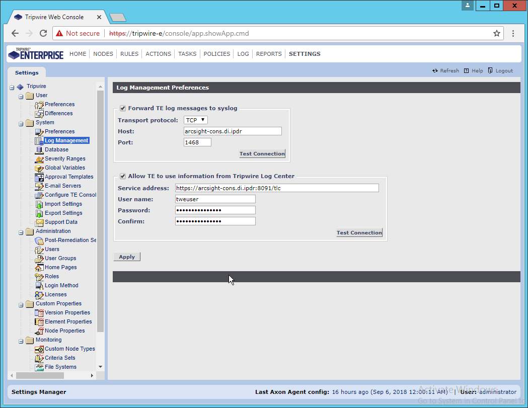
Click Apply when finished.
Go back to the Tripwire Log Center Console.
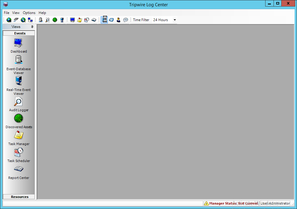
Click Configuration Manager.
Click Resources > Tripwire Enterprise Servers.
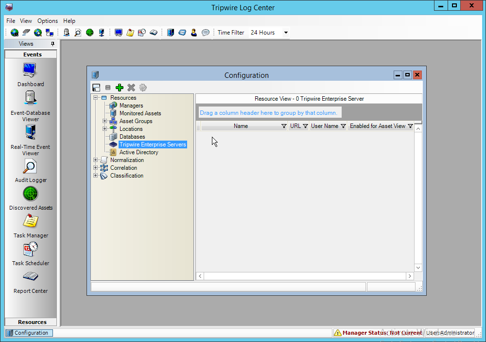
Click Add.
Enter a name for the server.
Enter the URL of the Tripwire Enterprise server.
Enter the name of a user account on the Tripwire Enterprise server. The account must have the following permissions: create, delete, link, load, update, view.
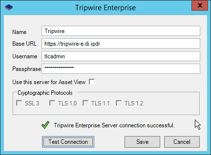
Click Save.
2.19 Integration: Tripwire Log Center and Tripwire IP360
2.19.1 Configure IP360 and Log Center
On the Tripwire Log Center Manager machine, navigate to C:\Program Files\Tripwire\Tripwire Log Center Manager\Agent Services\config.
Copy bridge_sample.properties to bridge.properties.
Modify the Pre-Shared Key to use a password by changing the following line (be sure to remove the “#” sign):
tw.cap.bridge.registrationPreSharedKey=newpasswordhereSave the file.
From the command line, run the following two commands:
> net stop TripwireBridge

> net start TripwireBridge
- On the Tripwire IP360 machine, from the command line, enter the following command to specify the hostname of the Tripwire Log Center (TLC) machine:
> tlc config bridge host update <hostname> Enter the following command using the preshared key specified earlier:
> tlc config bridge password update <password>Enter the following command to start the TLC service on the IP360 machine (this will use port 5670 on the TLC machine by default):
> system service tlc enableDownload the “Content update–June 2018” package from the Tripwire Customer Center.
Open the Tripwire Log Center Console.
Enter the username and password.
Click Login.
Click Options > Import TLC Content > Content.
Select Use a custom file.
Click Browse, and locate the zip file downloaded from the Tripwire Customer Center.
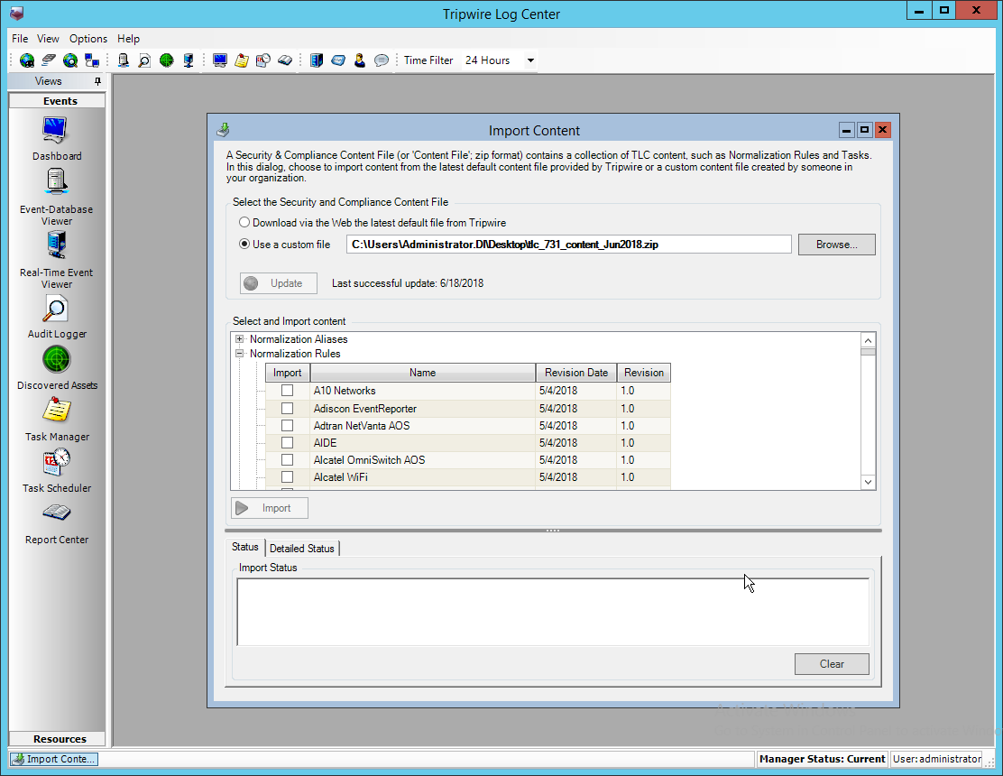
Expand the Normalization Rules section.
Check the box next to Tripwire IP360 VnE.
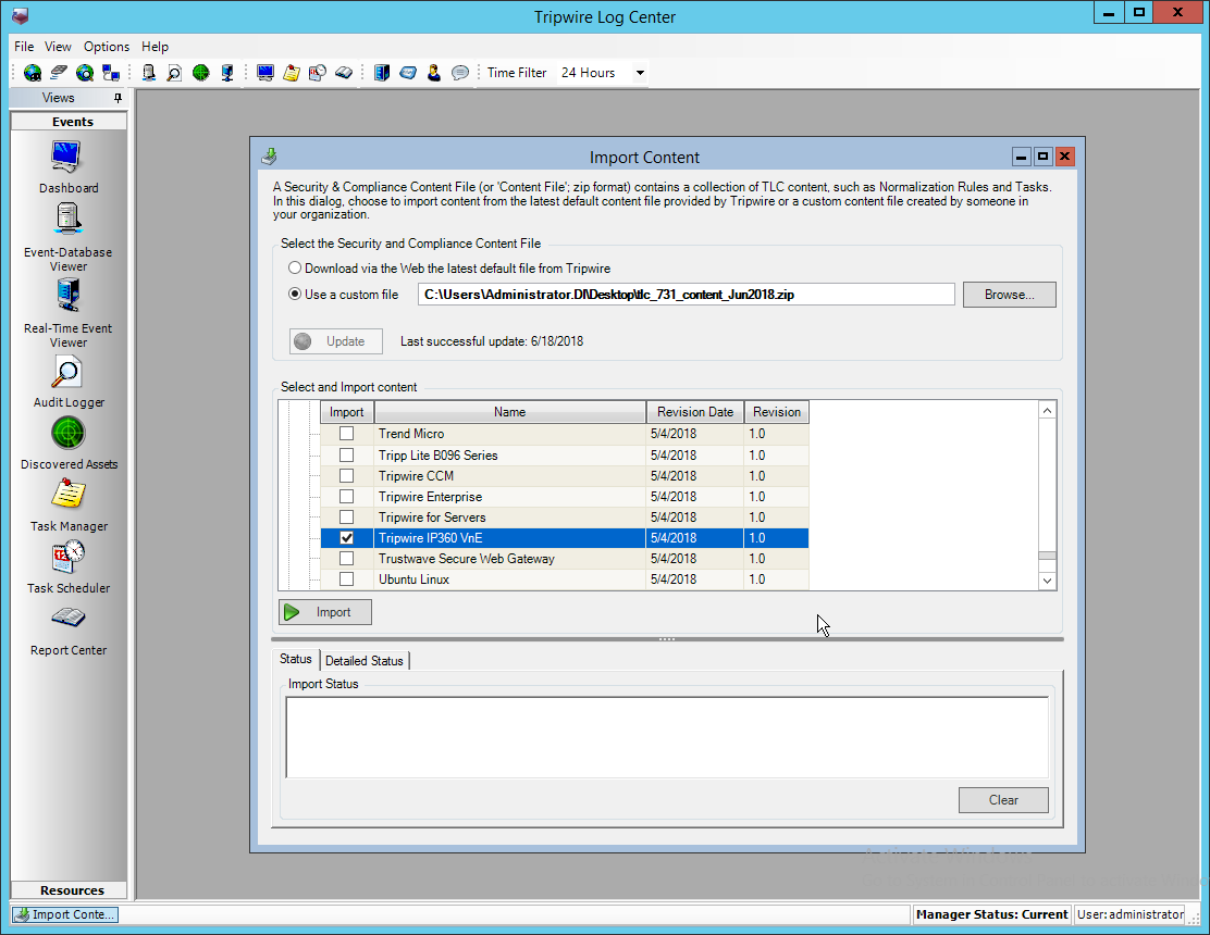
Click Import.
2.19.2 Collect Tripwire IP360 Operational Logs
Click Configuration Manager.
Click Resources > Managers.
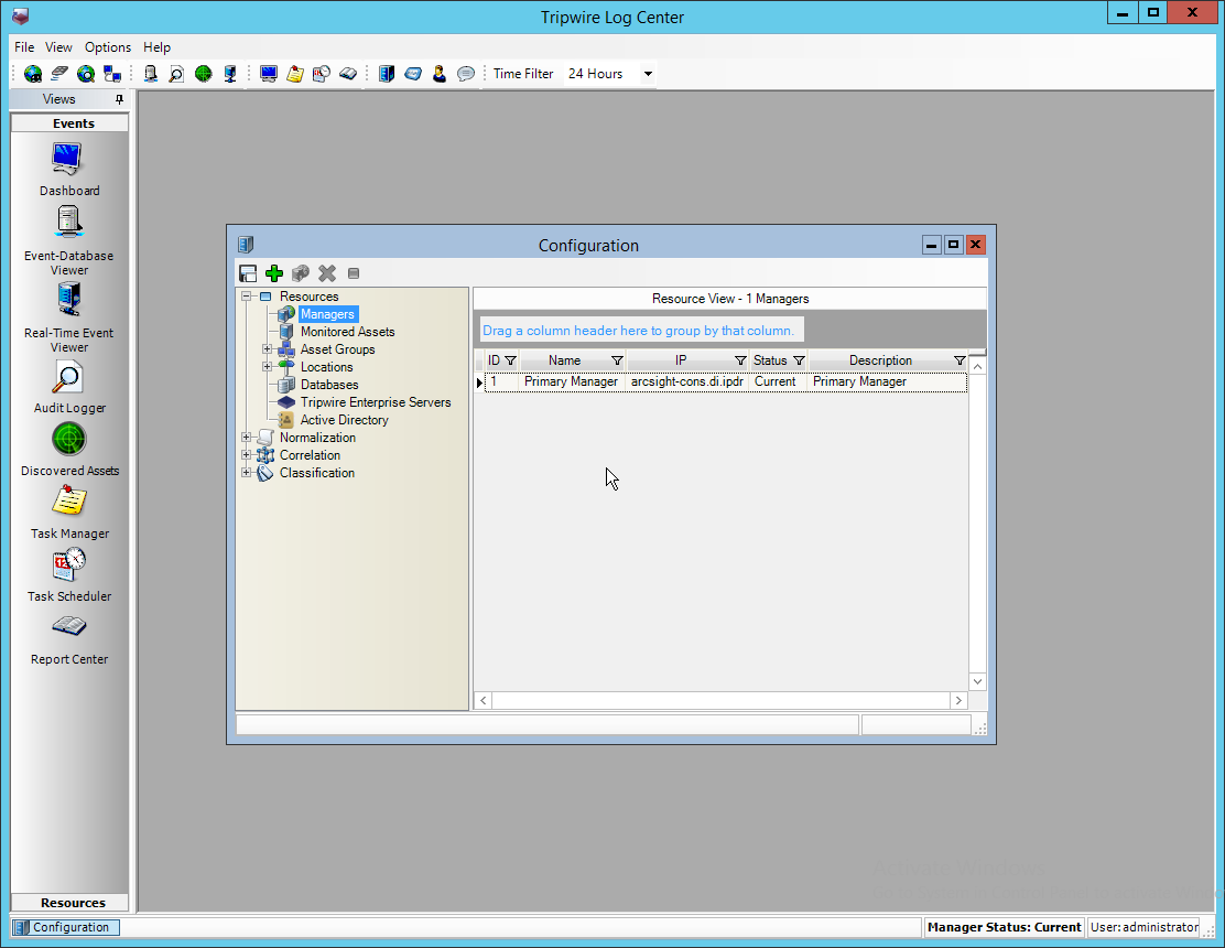
Double-click the Primary Manager.
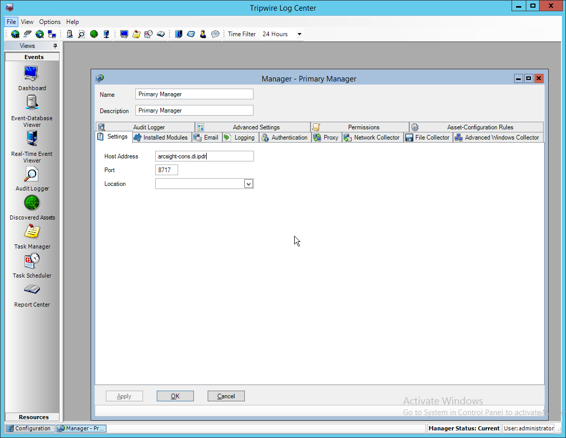
Click the Installed Modules tab.
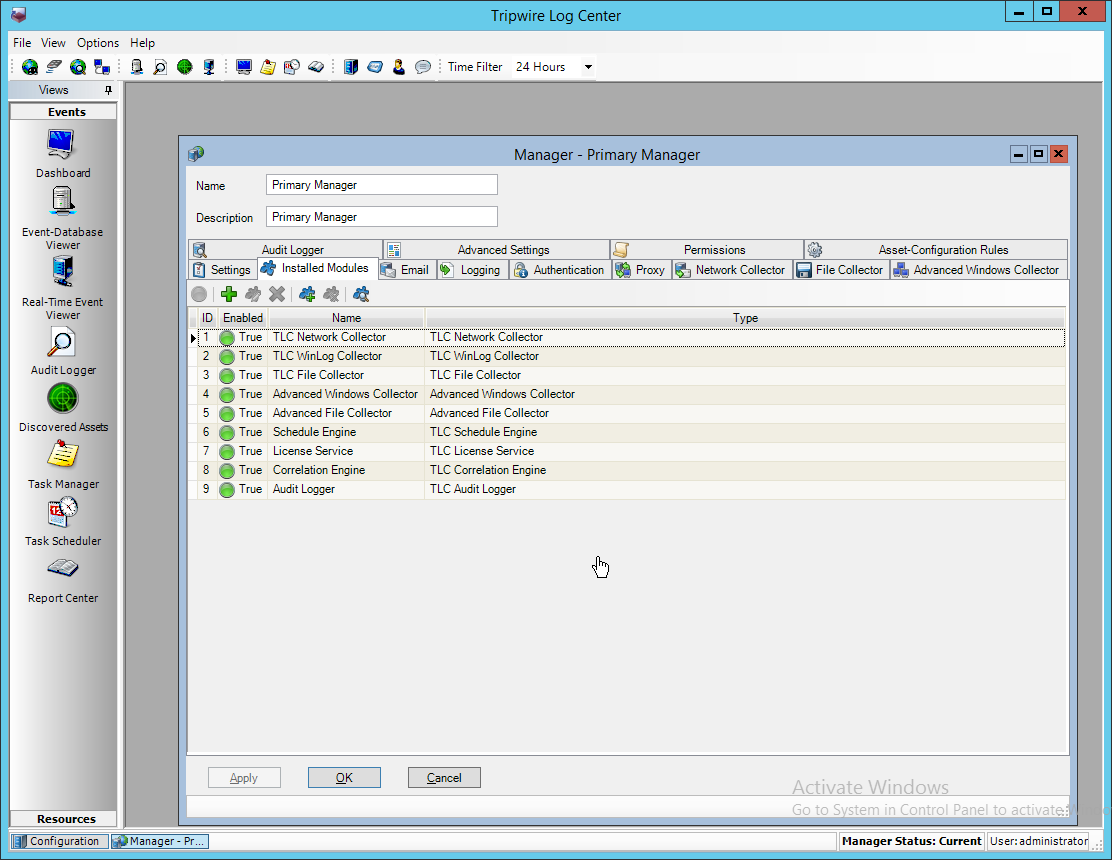
Ensure that there is an Advanced File Collector. If not, click the Create new module button, and specify a name. Set the type to Advanced File Collector. If there is an Advanced File Collector, skip this step.
Click OK.
Click Resources > Asset Groups.
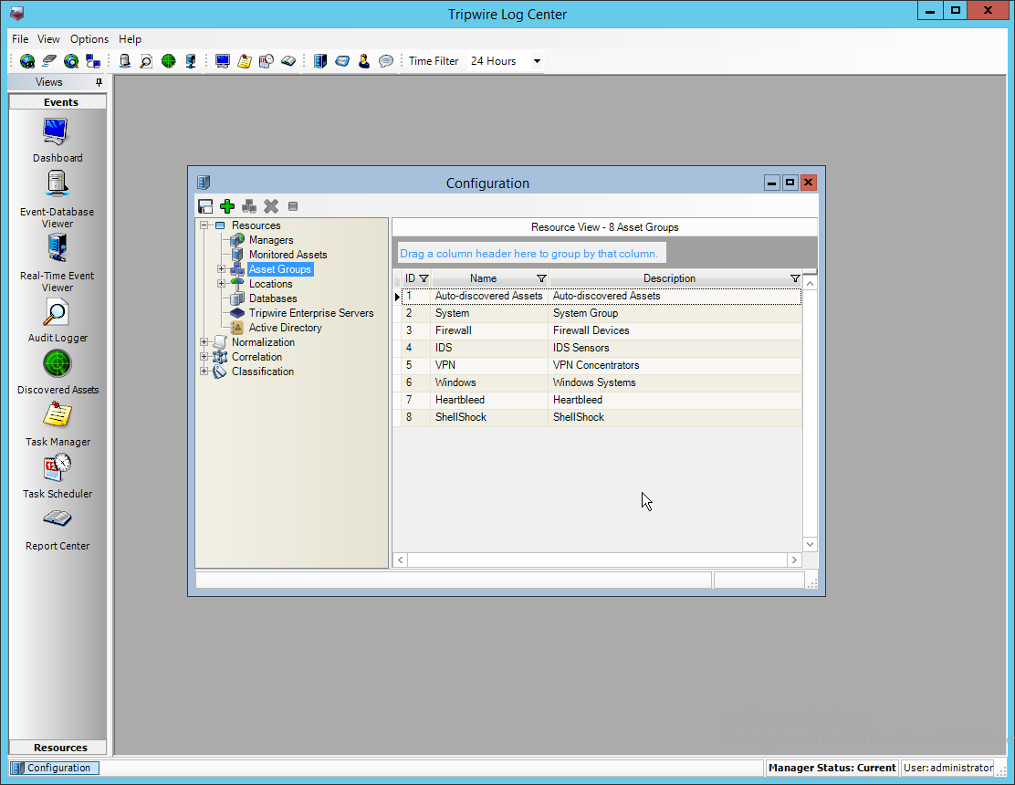
Click Add.
Enter Tripwire VnE Managers in the Name field.
Click the Normalization Rules tab.
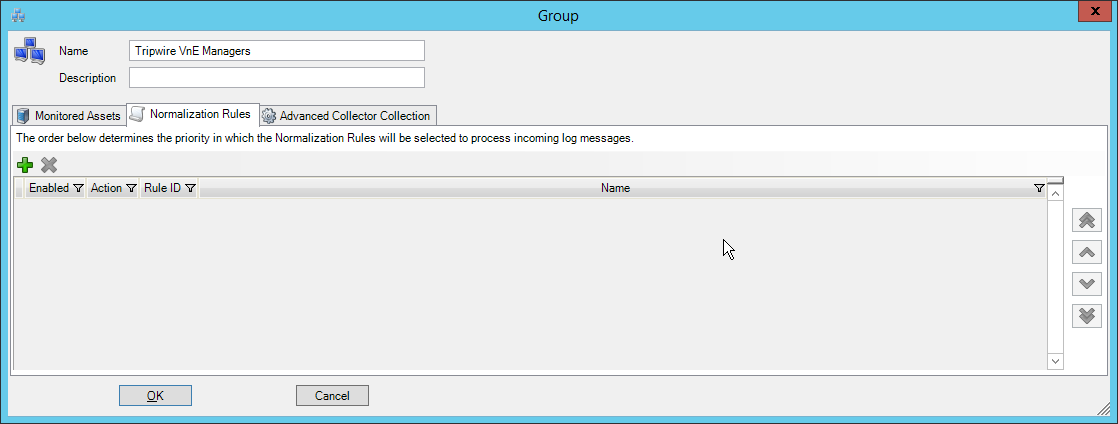
Click Add.
Expand the Tripwire IP360 VnE group.
Click the Check selected rows button at the top to check the box next to everything in this section.
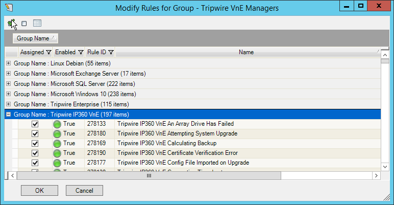
Click OK.
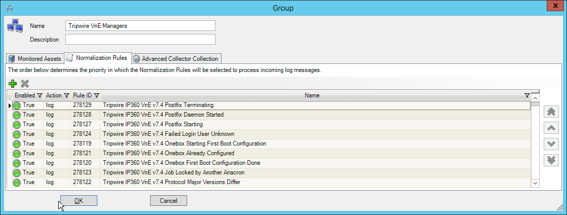
Click OK.
Click Resources > Monitored Assets.
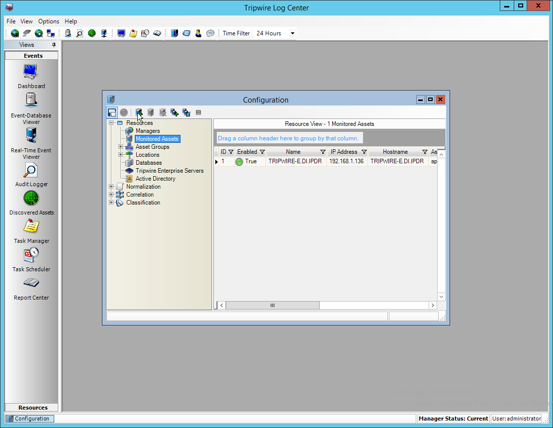
Click Add Monitored Asset.
Enter a name.
Select Advanced File Collector for Collector.
Select the IP360 server from the Hostname drop-down. It may appear as an IP address.
Enter the IP address of the server.
Select ips for Asset type.
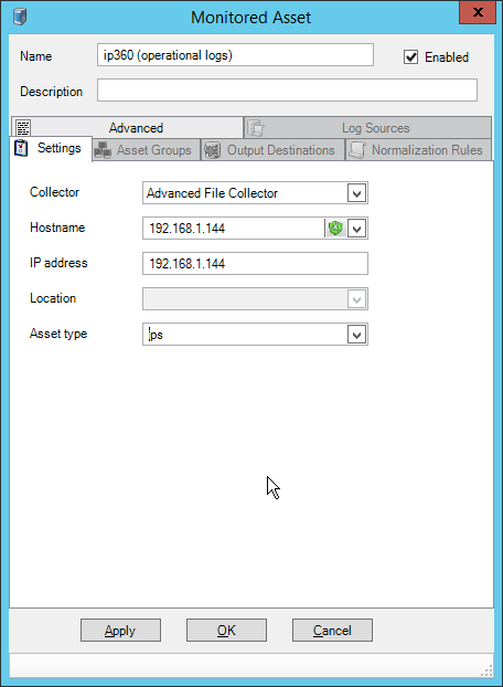
Click the Asset Groups tab.
Click Add.
Select Tripwire VnE Managers.
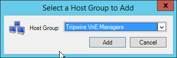
Click Add.
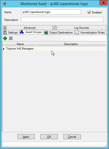
Click the Output Destinations tab.
Click Add.
Select File–Text File for Input Type.
Select Correlation Engine for Output Destination.
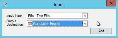
Click Add.
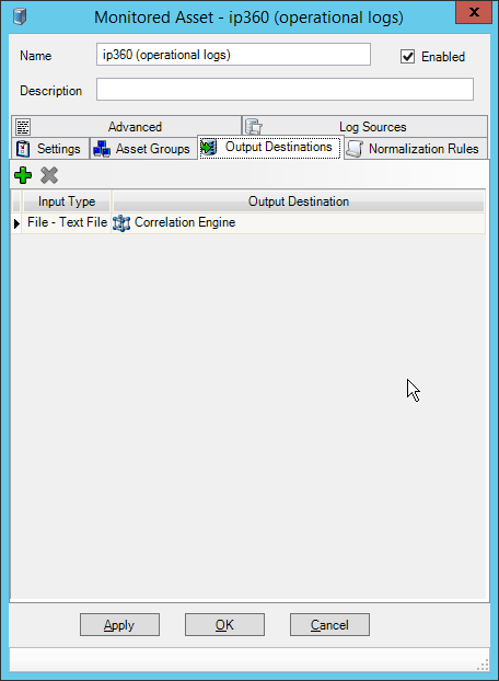
Click the Log Sources tab.
Click Add.
Enter a name for the log.
Enter /data/log/ironwood.log for Log file path.
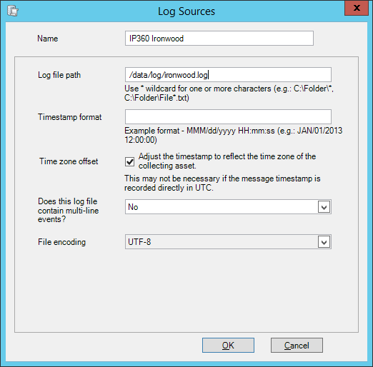
Click OK.
Click Add.
Enter a name for the log.
Enter /data/log/upgrade.log for Log file path.
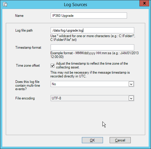
Click OK.
Click Add.
Enter a name for the log.
Enter /var/log/messages for Log file path.
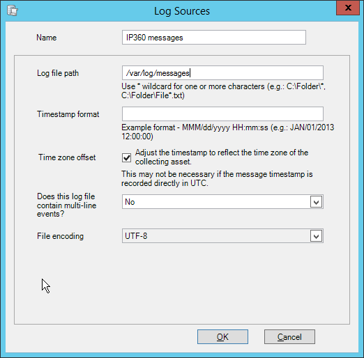
Click OK.
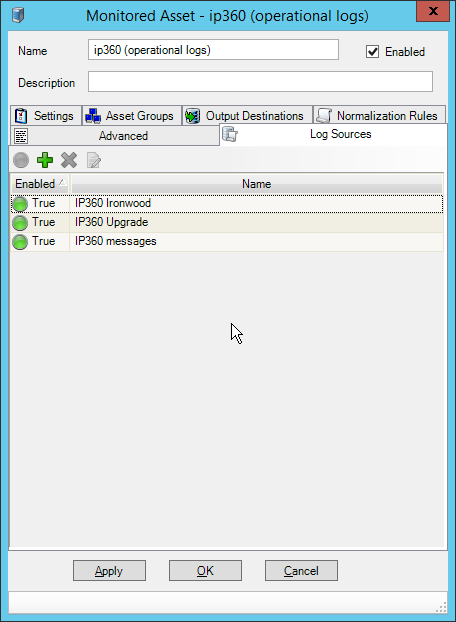
Click OK.
Click Resources > Managers.
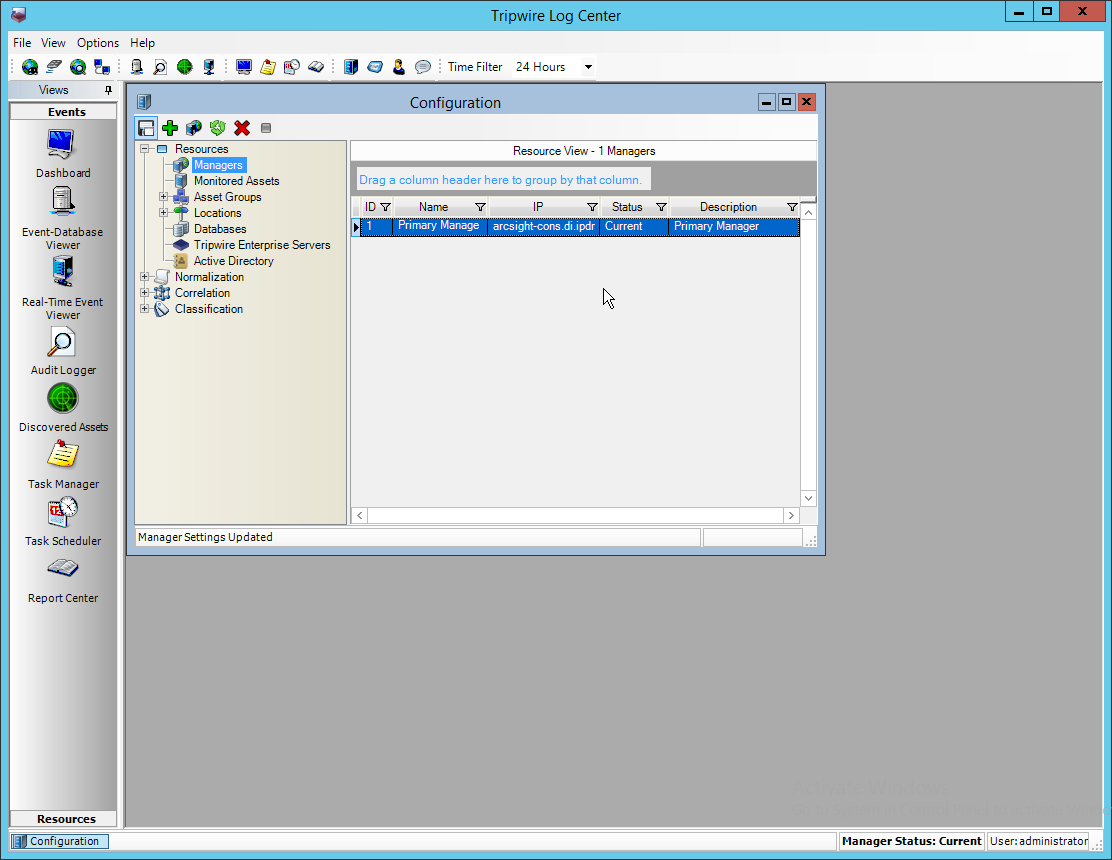
Select the Primary Manager and click Push Updates to Manager.
2.19.3 Configure Tripwire IP360 Scan Results Forwarding
Click Configuration Manager.
Click Resources > Manager.
Double-click the Primary Manager.
Click the Advanced Settings tab.
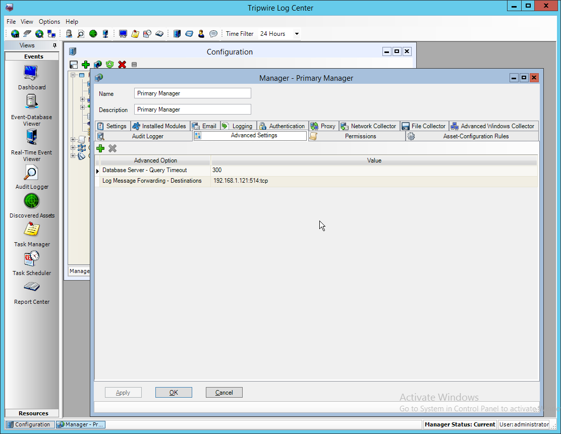
Click Add.
Select Vulnerabilities–IP360 High Value Host Threshold for the Advanced Option.
Enter a number between 0 and 999,999,999 for the Value. This number corresponds to the priority level of the host system being scanned. The value entered will be the minimum value for a host machine to be considered high priority. Half of this value will be the minimum value for a host machine to be considered medium priority.
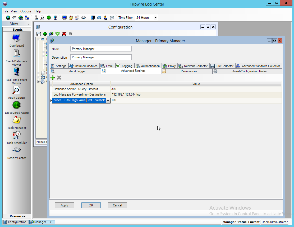
Click Add.
Select Vulnerabilities–IP360 High Risk Score Threshold for the Advanced Option.
Enter a number between 0 and 999,999,999 for the Value. This number corresponds to the risk level of a vulnerability event. The value entered will be the minimum value for an event to be considered high risk. Half of this value will be the minimum value for an event to be considered medium risk.
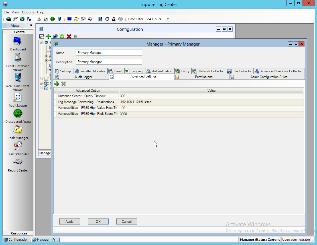
Click Apply.
Click OK.
Click Resources > Monitored Assets.
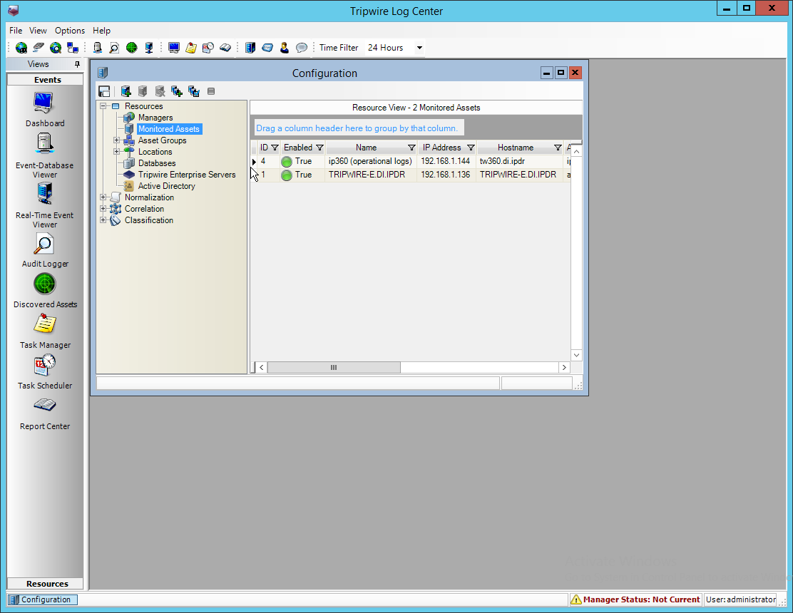
Click Add Asset.
Select TLC File Collector for Collector.
Enter the IP address of the IP360 machine.
Select ips for Asset type.
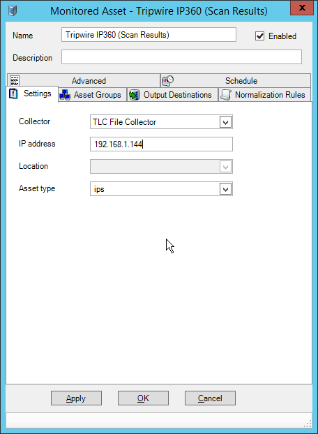
Click the Asset Groups tab.
Click Add.
Select Tripwire VnE Managers for Host Group.
Click Add.
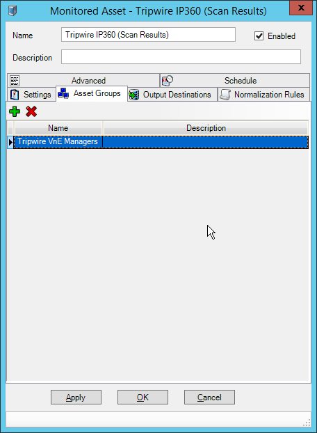
Click the Output Destinations tab.
Select File–IP360 for Input Type.
Select Events for Output Destination.
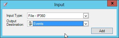
Click Add.
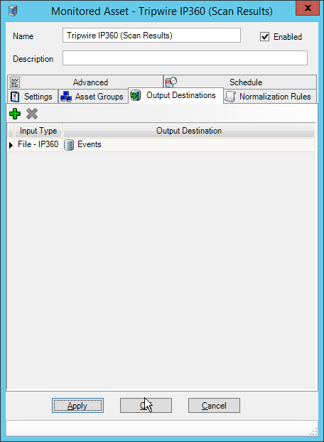
Click OK.
Click Resources > Managers.
Select the Primary Manager.
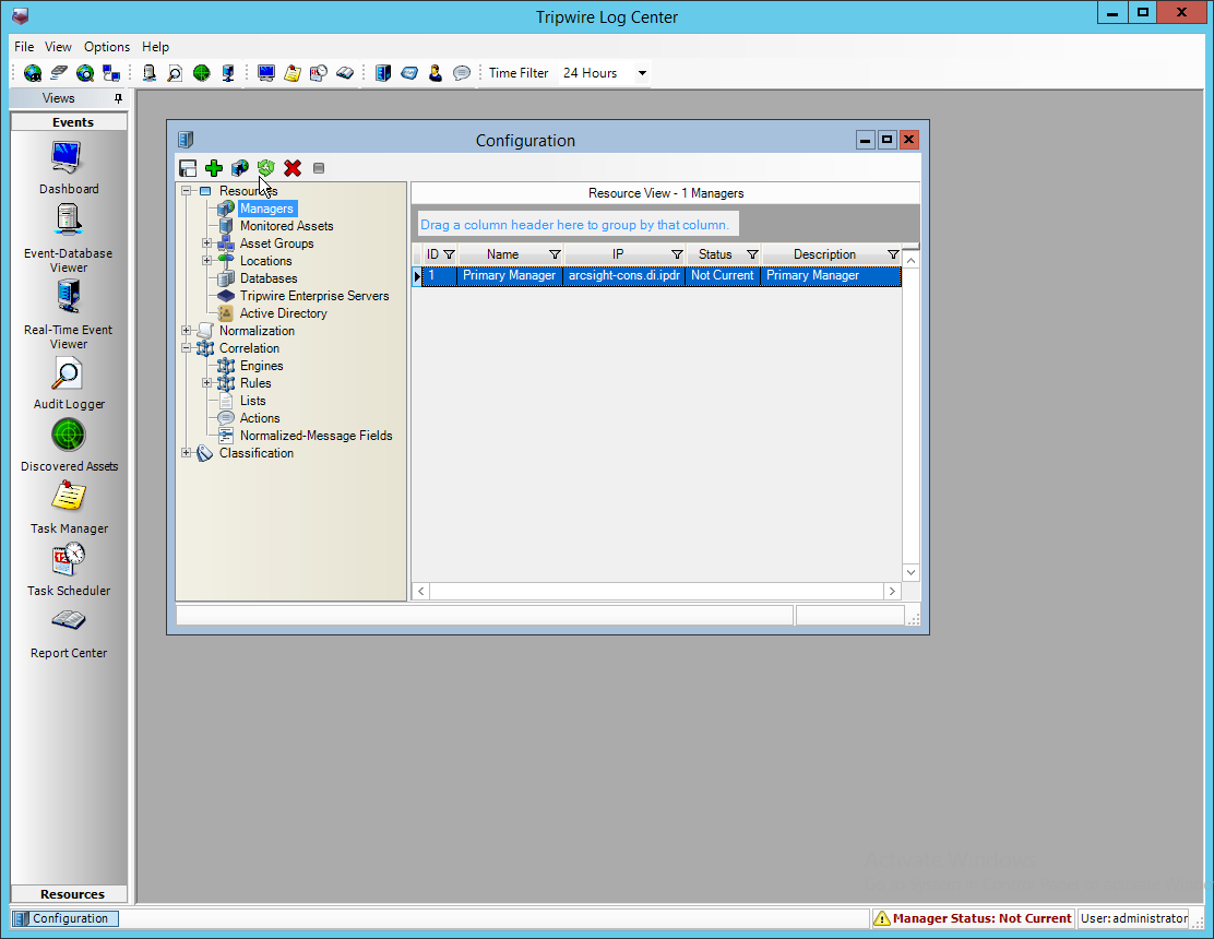
Click Push Update to Manager.
Log in to the Tripwire IP360 Web Console.
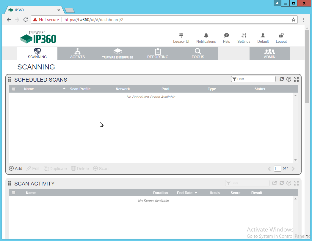
Click Legacy UI at the top.
On the left, click Administer > System > VnE Manager > Automated Export.
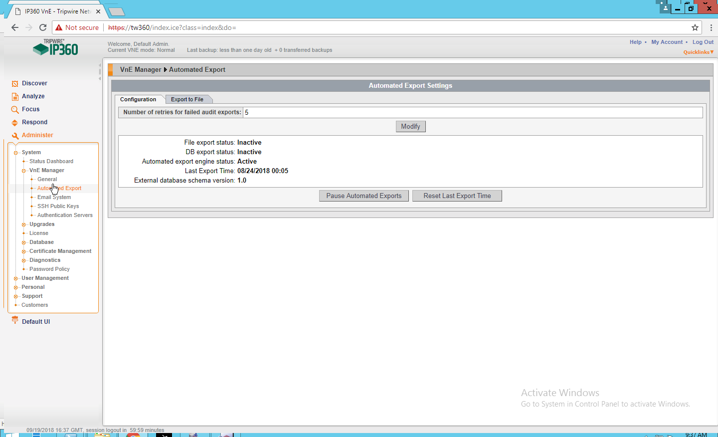
Click the Export to File tab.
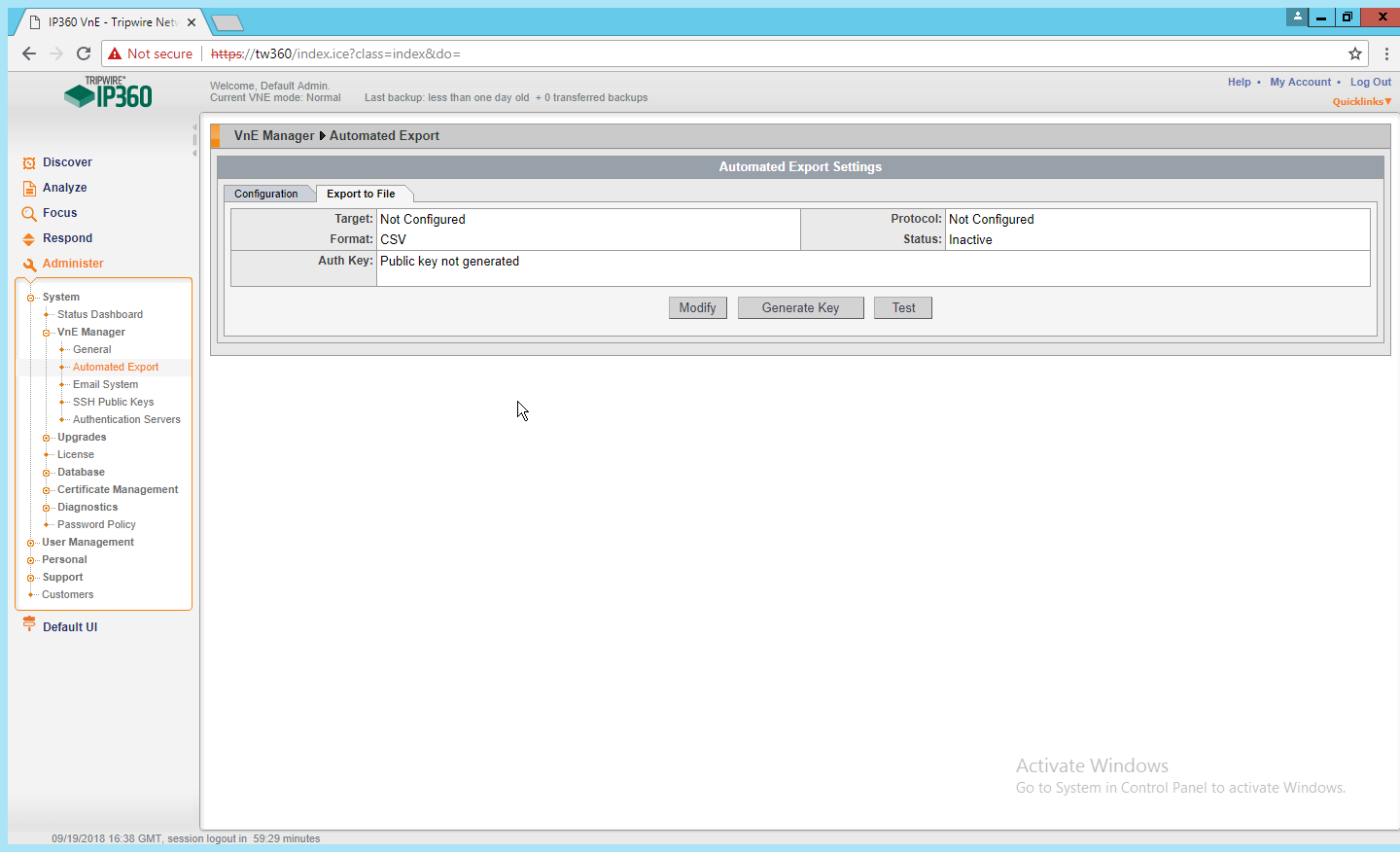
Click Modify.
Enter the username of a TLC user account for User.
Enter the IP address of the TLC Manager for Host.
Enter “/” for the directory.
Select Active.
Select SSH2 DSA (sftp) for Protocol.
Select XML2 for Format.
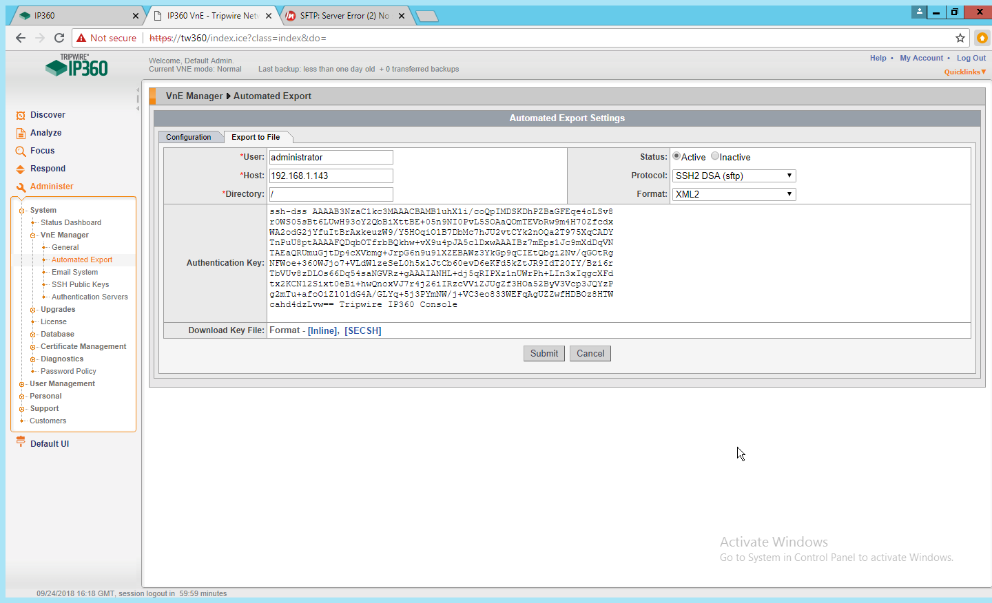
Click Submit.
Download the generated key by clicking [Inline].
In TLC Console, click Configuration Manager.
Click Resources > Managers.
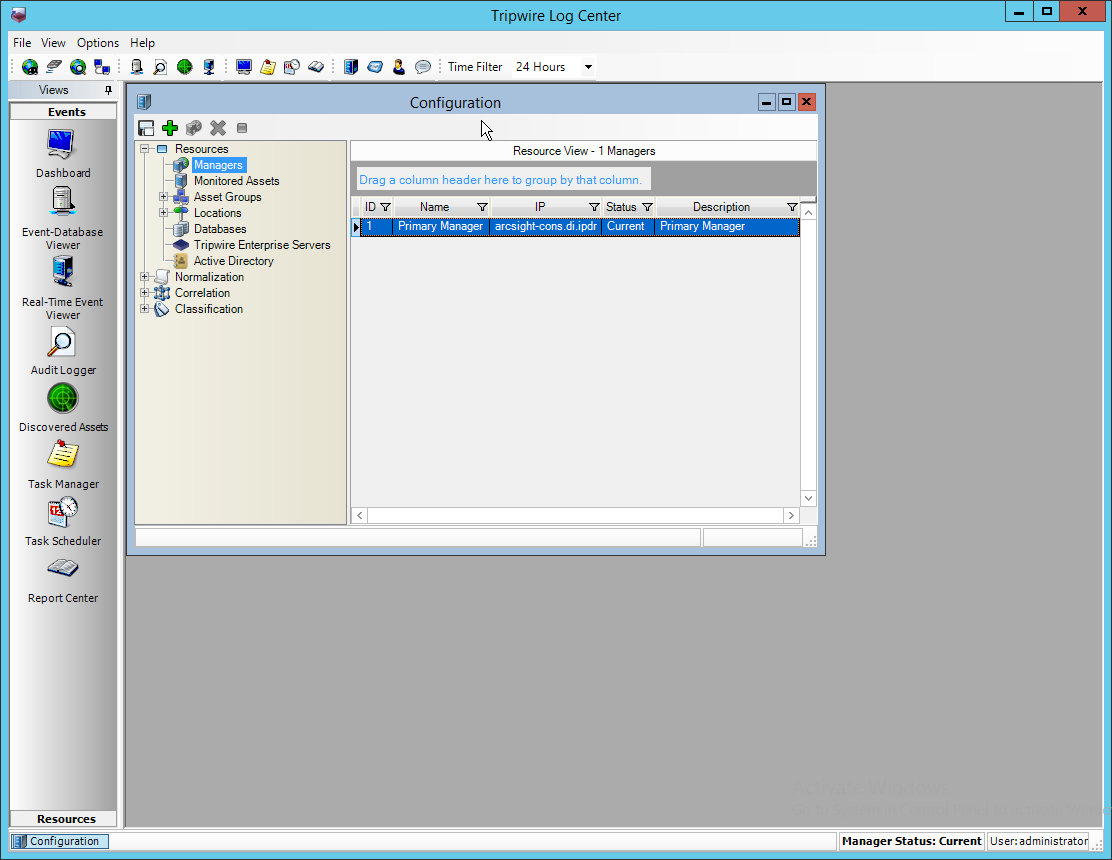
Double-click the Primary Manager.
Click the File Collector tab.
Ensure that the Collect log messages via FTP and SSH option is enabled.
Enter 22 for the port. (Note: The IP360 Integration Guide says to use a different port, but the IP360 system appears to be unable to use a port other than 22.)
Click Add.
Under Users, select the user for whom the key was generated.
Under Key Path, enter the path to the downloaded key.
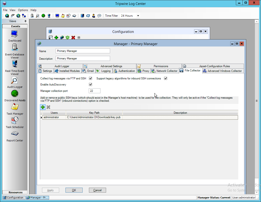
Click OK.
Select the Primary Manager.
Click Push Updates to Manager.
On the IP360 web console, click Test to ensure that the connection is successful.
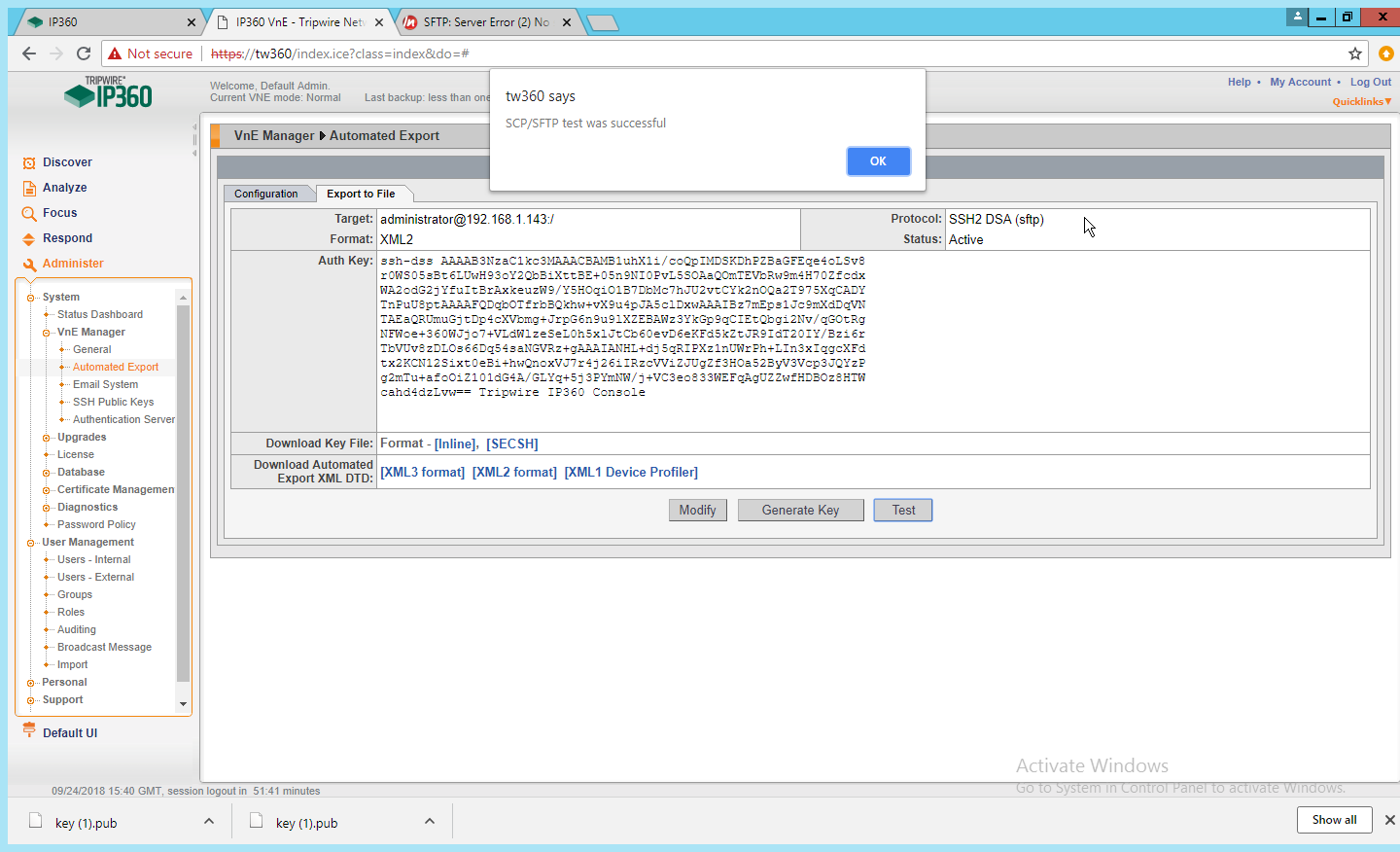
Any recurring scans will now forward the scan results to Tripwire Log Center. To ensure that a scan is recurring, select a scan in Scan Profiles on the main dashboard of the IP360 web console.
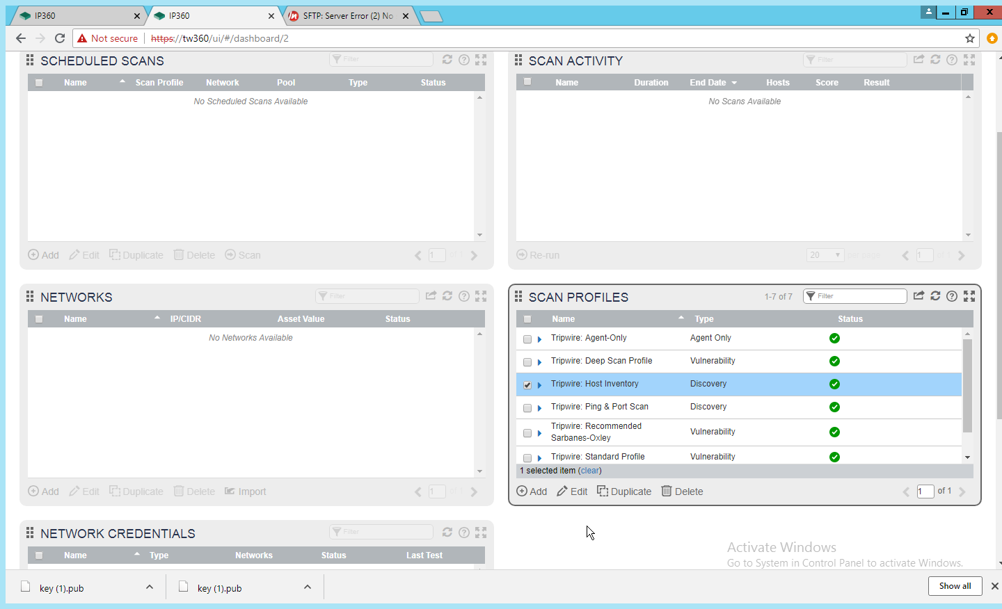
Click Edit.
Click Next until the Scan Schedule page.
Select Recurring, and set a schedule for the scan according to the needs of the organization.
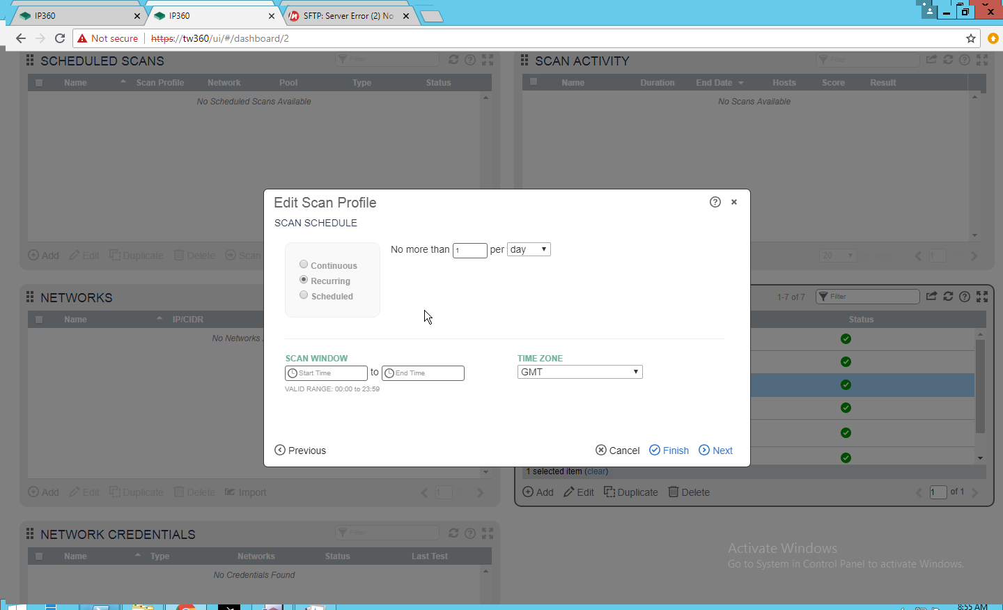
Click Finish.
2.20 Integration: Tripwire Enterprise and Backups
This section details how to back up Tripwire Enterprise configuration data.
To back up Tripwire Enterprise integrity information, refer to the database vendor’s documentation for backing up data.
2.20.1 Export Configuration from Tripwire Enterprise
On the Tripwire Enterprise server, navigate to C:\Program Files\Tripwire\TE\Server\bin.
Run the following command to stop Tripwire Services.
> twservices stopRun the following command to export the configuration files to a backup (replace config.bak with the desired name of the backup).
> tetool backup config.bakRun the following command to restart Tripwire Services.
> twservices start
2.20.2 Back Up the Tripwire Enterprise Configuration
The configuration backup will be stored in the file specified in step 3 of the previous section. To back this up to the enterprise backup server through a Duplicati client, see the documentation in Section 2.8.4 for how to set up a Duplicati instance on the Tripwire Enterprise server, and then simply select the configuration file.
2.21 Integration: Cisco ISE and CryptoniteNXT
This section details an integration between Cisco ISE and CryptoniteNXT, allowing ISE to dictate the Cryptonite registration process based on the posture of the client machine. Please see the CryptoniteNXT Generic RADIUS Integration Guide for more details about the integration.
2.21.1 Requirements for Integrating Cisco ISE and CryptoniteNXT
As described in the ISE installation section, ISE requires RADIUS to be configured to perform posture. As such, this guide assumes the use of some sort of switch to provide RADIUS functionality.
CryptoniteNXT requires the switch to use L2 technologies for the RADIUS server, which means a captive portal will not work for this scenario. The feasibility of this depends on your networking setup.
This integration requires the following:
The switch is bridged to CryptoniteNXT.
Cryptonite is configured to accept RADIUS packets from the switch (detailed below).
Clients on the switch’s Local Area Network (LAN) authenticate to the switch via 802.1x (see your switch’s documentation).
The switch is configured to accept CoA packets from ISE (see ISE installation).
The switch sends RADIUS accounting and authentication packets to Cisco ISE (see ISE installation).
ISE sends an authentication response to the switch and then later uses CoA to modify the authorization based on posture (see ISE installation).
If the authorization is successful, the switch tells the client and forwards the accounting packets to the CryptoniteNXT ACC node (see your switch’s documentation).
2.21.2 Configuring CryptoniteNXT for RADIUS
Open the CryptoniteNXT GUI and log in.
Navigate to the CryptoniteNXT Nodes tab.
Click Enable Editing.
Select the Endpoint node, which will have your switch attached to it.
Under Endpoint Node-Specific Configuration, select Strict Access for Access Control.
Select After Delay for the next field.
Enter -1 for Captive Portal delay.
Enter 5 for the Registration delay.
Select the Gateway node.
Click Save.
Navigate to the Integration tab.
Under Built-In RADIUS Configuration, check the box next to Enable Built-In RADIUS Accounting Server.
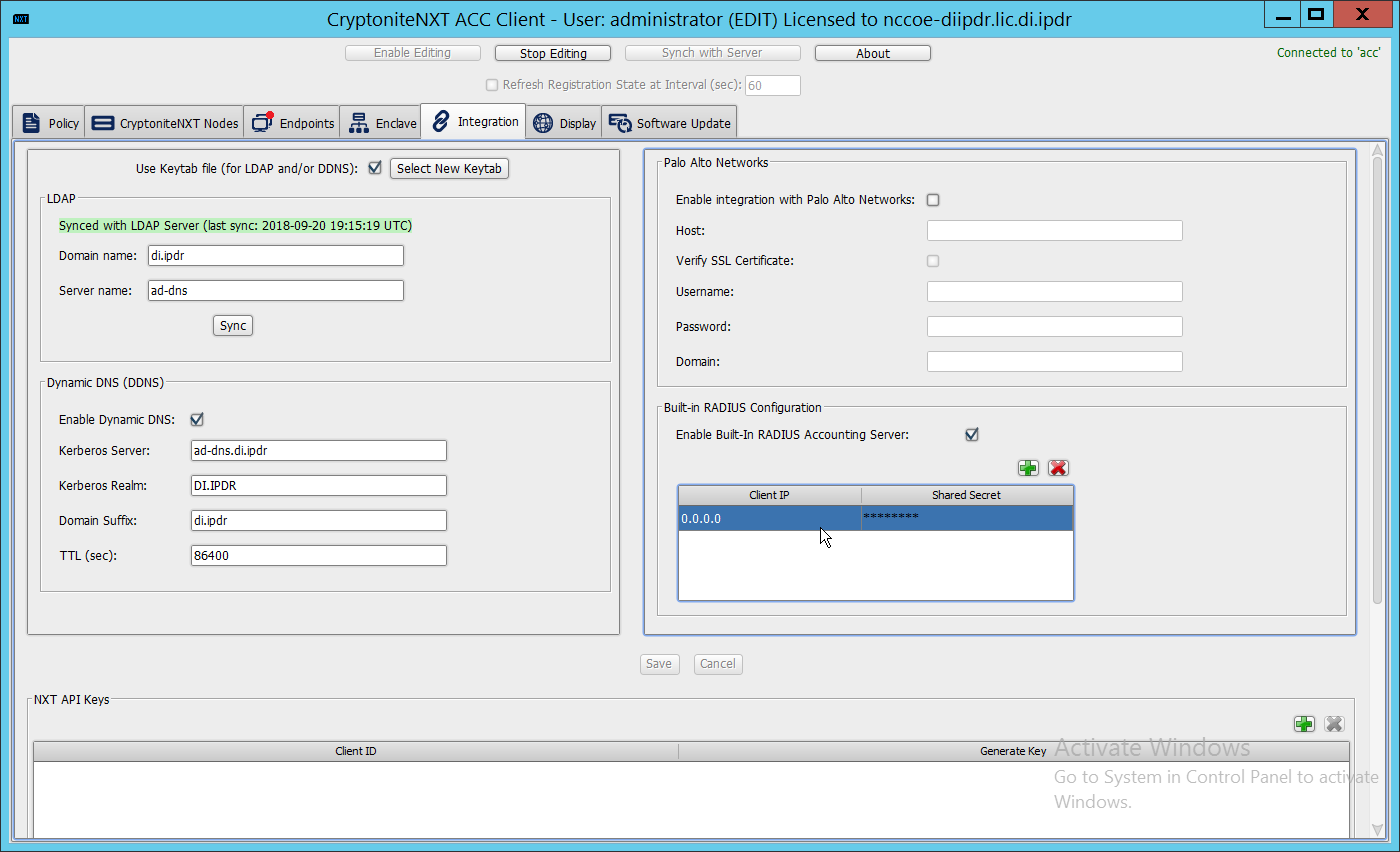
Click the plus button to add the IP of the switch as well as a shared secret. You can use 0.0.0.0/0 as the IP to accept RADIUS Accounting packets from all IPs, however this is not recommended in production.
2.22 Integration: Backups and GreenTec
This section details integration between the backup capability and GreenTec WORMdisks. Because GreenTec WORMdisks provide write protection for files on the disk, they are an ideal place to store important backups. There are a couple options for this integration, but before these backups can be replicated onto secure storage, it is important to be able to identify the location of backups to be replicated.
2.22.1 Locate Backups with FileZilla and Duplicati
To locate backups in FileZilla, open the FileZilla Server console.
Click Edit > Users.
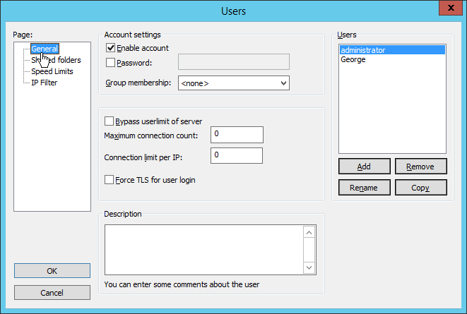
Click Shared folders in the left pane.
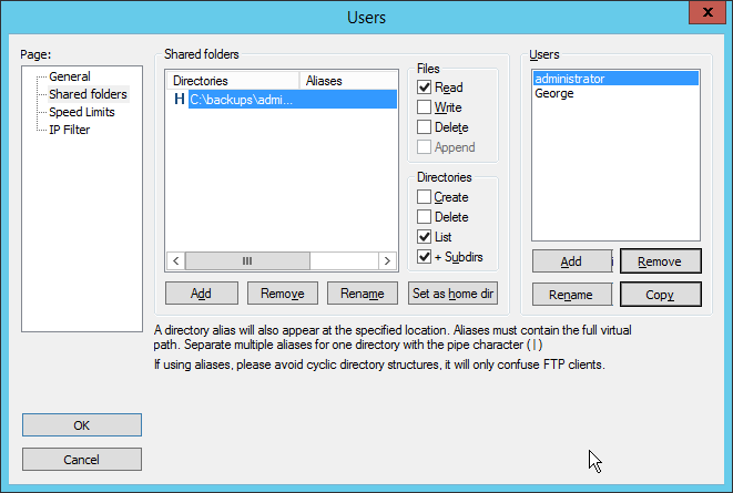
Under Directories is a list of directories in which the selected user can store backups. The one marked H is the default home directory.
The path to the backups from the home directory is specified in the Path on server field in Duplicati (see Section 2.8.6).
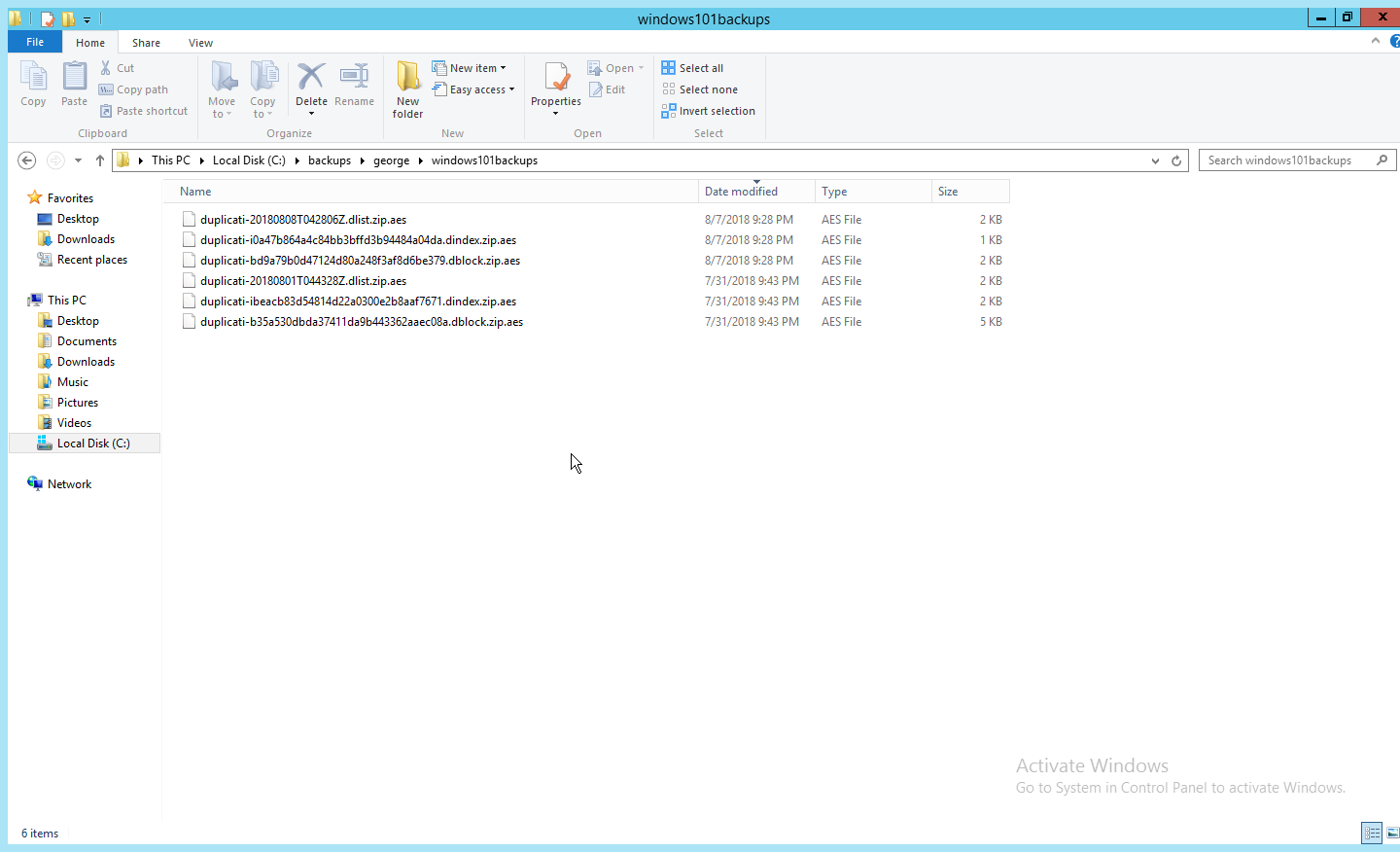
Each backup should have three associated files. An easy way to determine what files belong together is to check the Date Modified field. These files are encrypted.
2.22.2 Back Up to a GreenTec Disk
The first, most flexible option involves backing up the backup server to a separate server with GreenTec WORMdisks. Simply set up a FileZilla server on the GreenTec storage server and a Duplicati client on the backup server (see Section 2.8 for these installation processes). When choosing where to store files on FileZilla, indicate a folder on the GreenTec WORMdisk. Sectors of the disk can be locked using the mechanism in Section 2.6.4, providing firmware-level write security for any backups in the locked sectors.
There are some considerations when doing this. First, if this is done on a schedule and permanent locks are used, space will be consumed quickly and the WORMdisks will need replacements as the space cannot be reused. The trade-off between space and backup frequency must be considered–a lower backup frequency inevitably means more data loss in the event of a restoration, while higher backup frequency increases the cost of maintaining secure storage.
Alternatively, secure storage can be used for specific types of backups, such as “golden disks”–which would contain backups of the basic level of functionality required for the enterprise without necessarily utilizing a backup schedule. This would afford protection for some basic functionality but would forfeit the secure storage capability for day-to-day data.
In addition to the options above, there are other ways to minimize wasted space on a GreenTec disk. Temporary Locks, or TLocks, can be employed after the data is backed up to a GreenTec disk to protect data integrity while making less space unavailable for future use. After the drive is full, a permanent lock should still be executed. Wasted space can also be minimized with the use of dynamic partitions, or with the Force-Field Write-Once File System, which can also reduce the overhead administration of the GreenTec disk.
2.22.3 Configure Network-Accessible GreenTec Disk
Another option for GreenTec disks is to make them network accessible. This allows them to be used specifically in situations where secure storage protection is desired, and it makes them options for backup locations even on servers to which they are not necessarily physically connected.
To configure a GreenTec disk to be network accessible, right-click the disk on the GreenTec server.
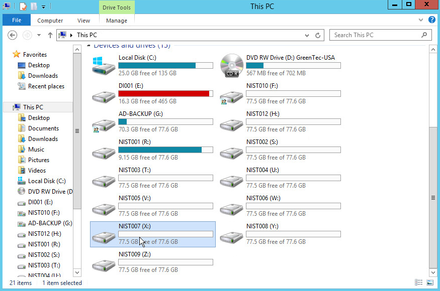
Click Share With > Advanced Sharing.
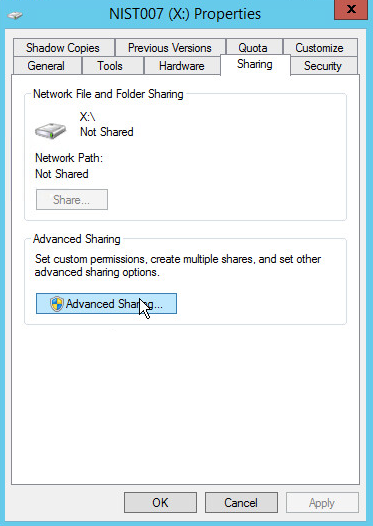
Click Advanced Sharing.
Check the box next to Share this folder.
Enter a name for the drive if desired.
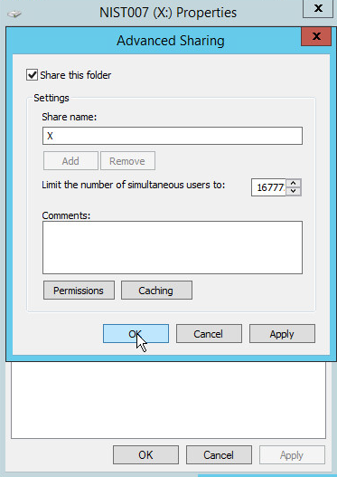
Click OK.
Click Close.
The drive should now be accessible at //SERVER-NAME/X.
2.22.4 Secure Storage for Semperis ADFR
On the Semperis ADFR server, the default backup location is C:\Semperis.
In this folder there is metadata for the backups (C:\Semperis\ADFR) as well as the backups themselves (C:\Semperis\BackupStore).
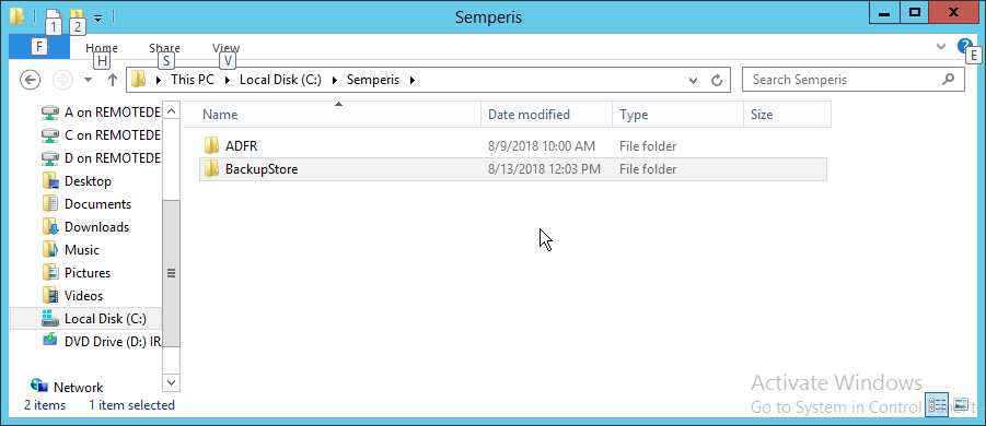
It is important to consider the limitations of the backup software when considering whether to replicate backups to secure storage. Ideally, the replication of backups ensures that they can be used on a separate server when the original server is affected by an incident. The replication of backups in this case can offer some write protection for these specific backup files, but if the entire server is lost, it is not guaranteed that the backups will be usable on a new instance of ADFR. This risk can be mitigated by exporting the configuration of the ADFR server for the purpose of building a failover ADFR server.
Though these backups can be replicated to WORMdisks, this is currently not supported by Semperis ADFR. Instead, Semperis ADFR offers a different type of “secure storage” by not joining to the domain, allowing the machine to be taken offline and brought online only during creation/application of a backup.
2.23 Integration: Micro Focus ArcSight and FileZilla
In this section an integration between ArcSight and FileZilla is detailed so that logs from FileZilla are forwarded to ArcSight by using an ArcSight syslog file connector.
2.23.1 Enable Logs in FileZilla
On the server with FileZilla installed, open FileZilla Server.
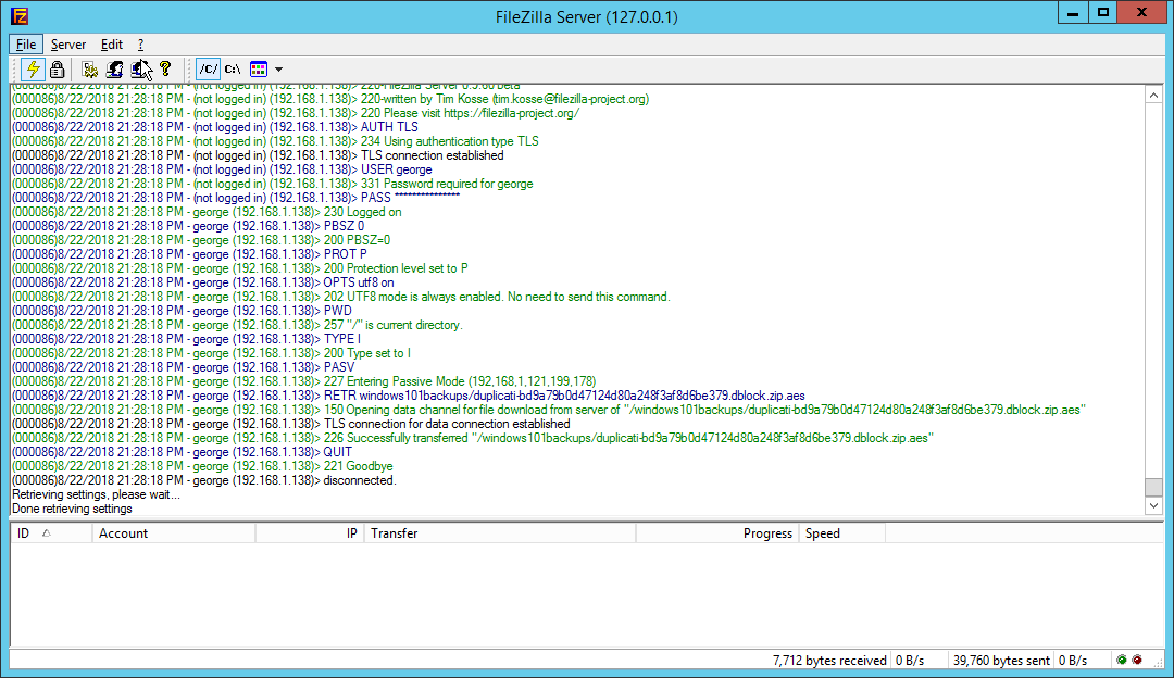
Click Edit > Settings.
Click Logging.
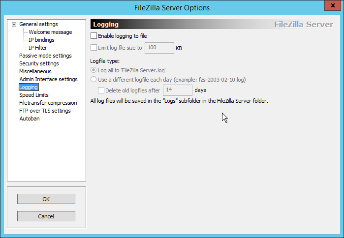
Check the box next to Enable logging to file.
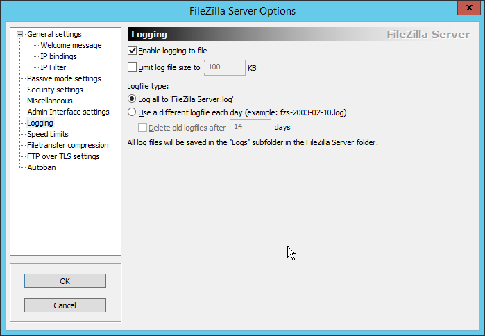
Click OK.
2.23.2 Install Micro Focus ArcSight
Run ArcSight-7.9.0.8084.0-Connector-Win64.exe.
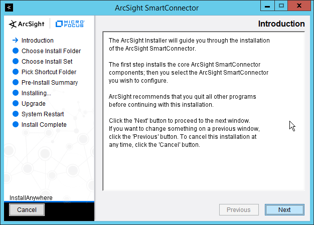
Click Next.
Enter C:\Program Files\ArcSightSmartConnectors\Windows.

Click Next.

Click Next.
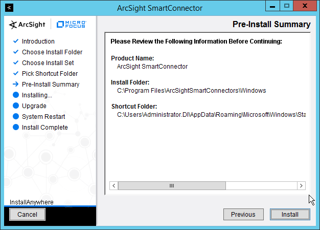
Click Install.
Select Add a Connector.

Click Next.
Select Syslog File.

Click Next.
Enter C:\Program Files (x86)\FileZilla Server\Logs\FileZilla Server.log for File Absolute Path Name.

Click Next.
Select ArcSight Manager (encrypted).

Click Next.
Enter the hostname, port, username, and password for the ArcSight ESM server.

Click Next.
Enter identifying details about the system (only Name is required).

Click Next.
Select Import the certificate to connector from destination.
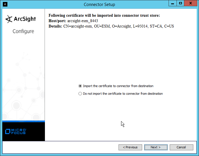
Click Next.

Click Next.
Select Install as a service.
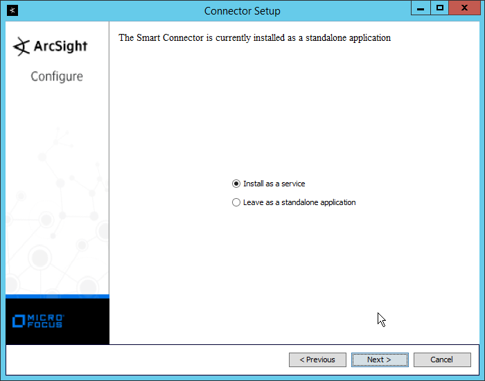
Click Next.
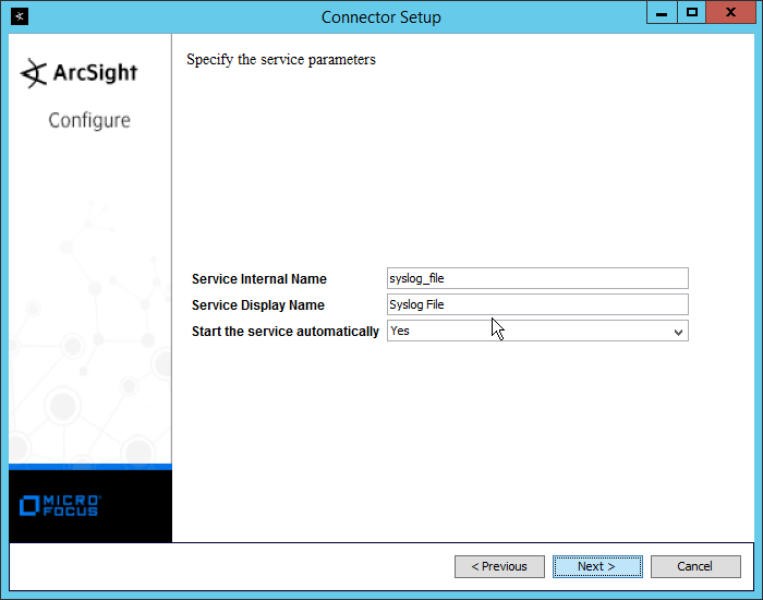
Click Next.
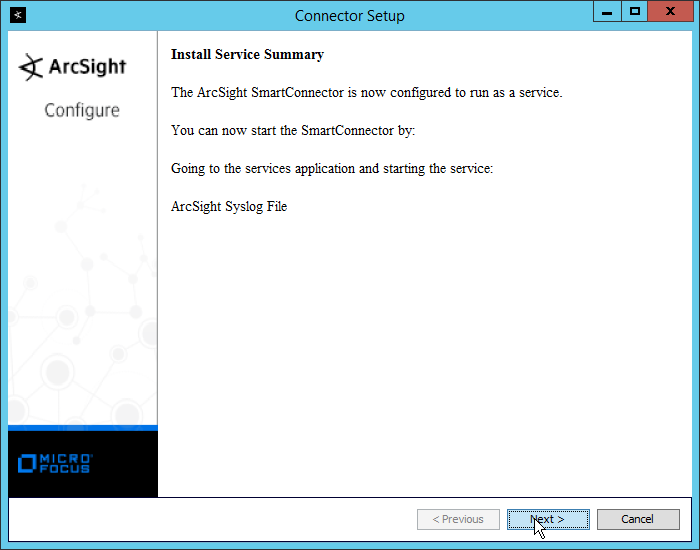
Click Next.
Select Exit.
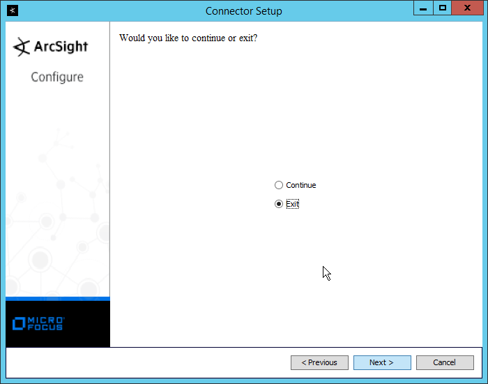
Click Next.
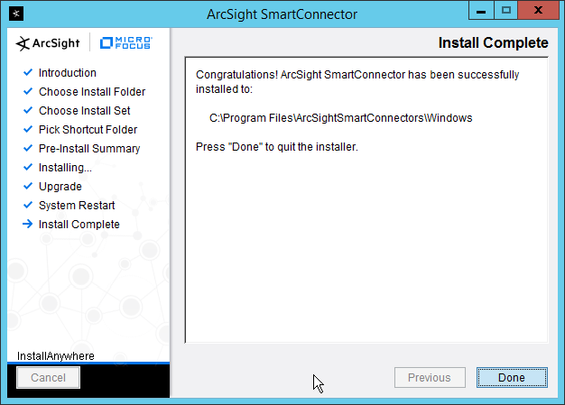
Click Done.
2.24 Integration: Micro Focus ArcSight and Tripwire
This section details forwarding logs from Tripwire Log Center to Micro Focus ArcSight. This will forward Tripwire IP360 and Tripwire Enterprise logs to ArcSight, assuming those logs are being collected by Tripwire Log Center.
2.24.1 Install Micro Focus ArcSight
Run ArcSight-7.9.0.8084.0-Connector-Win64.exe on any server except the one running Tripwire Log Center.
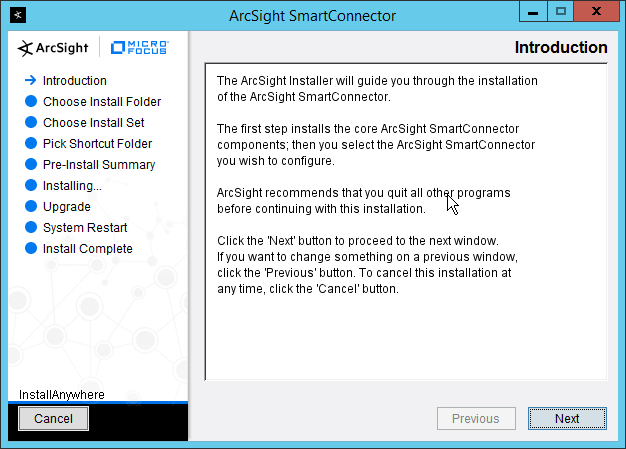
Click Next.
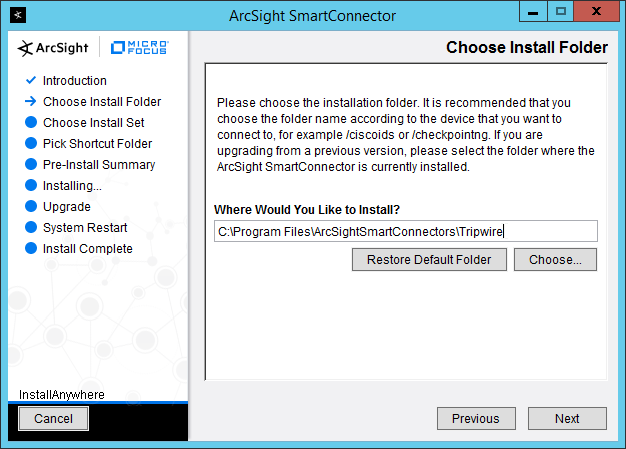
Enter C:\Program Files\ArcSightSmartConnectors\Tripwire.
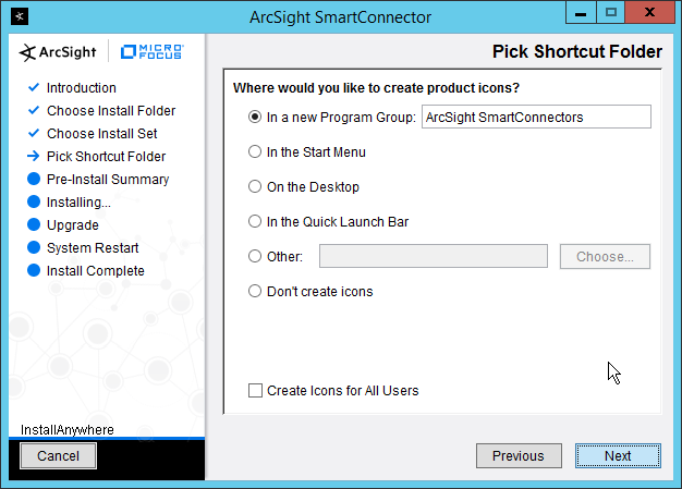
Click Next.
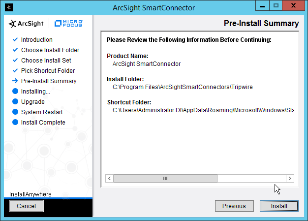
Click Install.
Select Add a Connector.
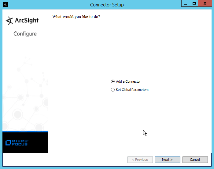
Click Next.
Select Syslog Daemon.

Click Next.
Enter a port for the daemon to run on.
Select Raw TCP for Protocol.

Click Next.
Select ArcSight Manager (encrypted).
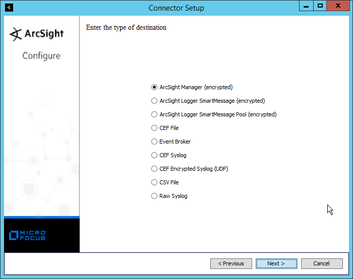
Click Next.
Enter the hostname, port, username, and password for the ArcSight ESM server.

Click Next.
Enter identifying details about the system (only Name is required).

Click Next.
Select Import the certificate to connector from destination.
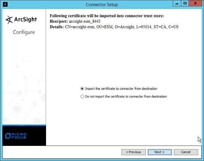
Click Next.

Click Next.
Select Install as a service.

Click Next.

Click Next.

Click Next.
Select Exit.

Click Next.
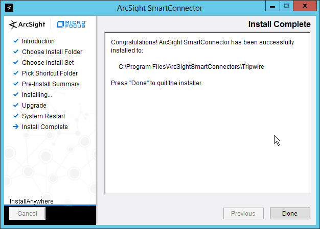
Click Done.
Open the Tripwire Log Center Console.
Go to the Configuration Manager.
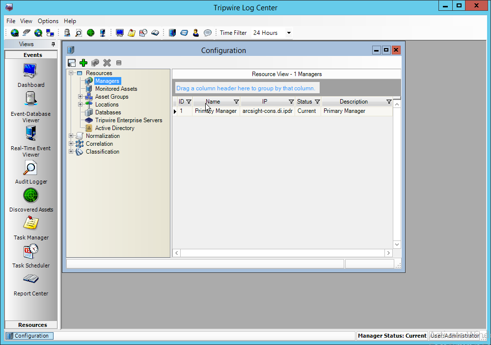
Select Resources > Managers.
Double-click the Primary Manager.
Click the Advanced Settings tab.
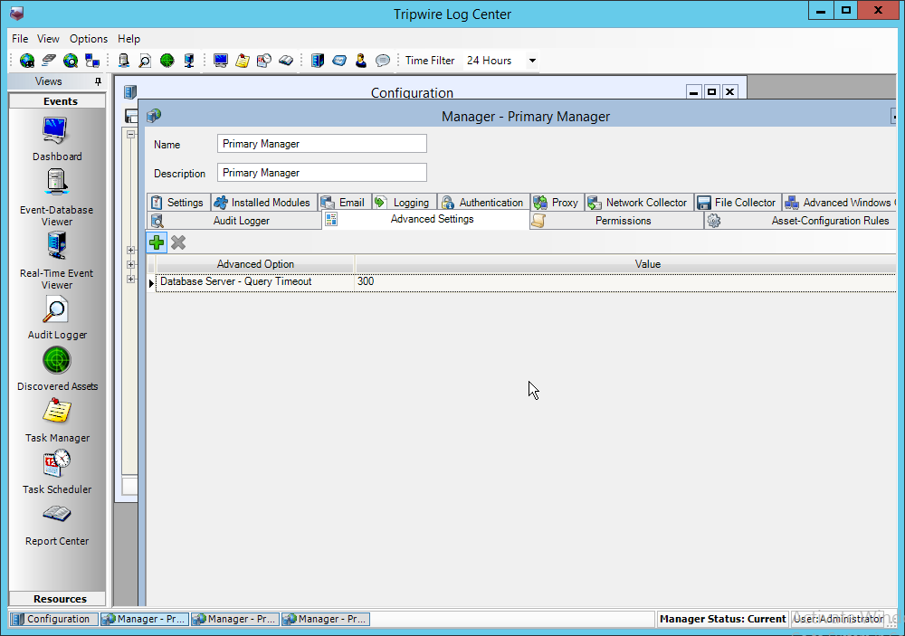
Click the Add button.
In the Advanced Option box select Log Message Forwarding–Destinations.
In the Value box next to it, type <ip_address>:<port>:tcp with the IP address and port of the syslog daemon just created.
Click OK.
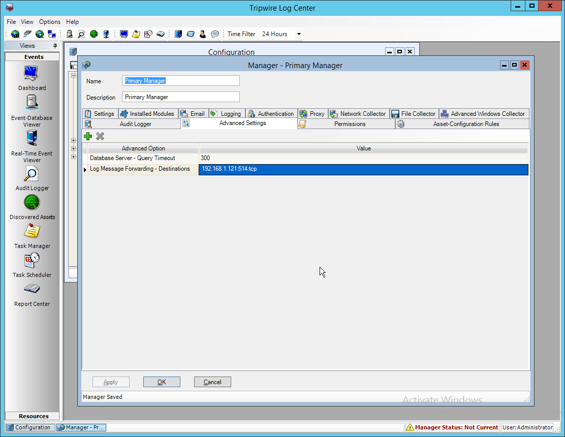
Click OK.
Restart the Tripwire Log Center Manager.
2.25 Integration: Micro Focus ArcSight and Cisco WSA
This integration briefly details how to send logs to an ArcSight syslog collector from Cisco WSA. Please see Section 2.24 for instructions for setting up an ArcSight syslog collector. If a server is already configured, you do not need to install a new one– simply forward logs to the address of that server.
2.25.1 Configure Cisco WSA to Forward Logs
In the Cisco WSA web client, navigate to System Administration > Log Subscriptions.
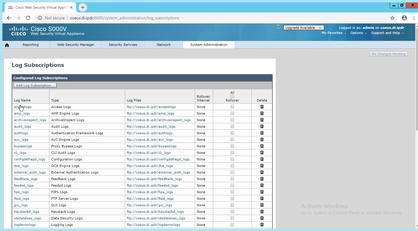
Click Add Log Subscription.
Select Access Logs for Log Type. (These are the logs of client web requests that have gone through the proxy.)
Enter a name for Log Name.
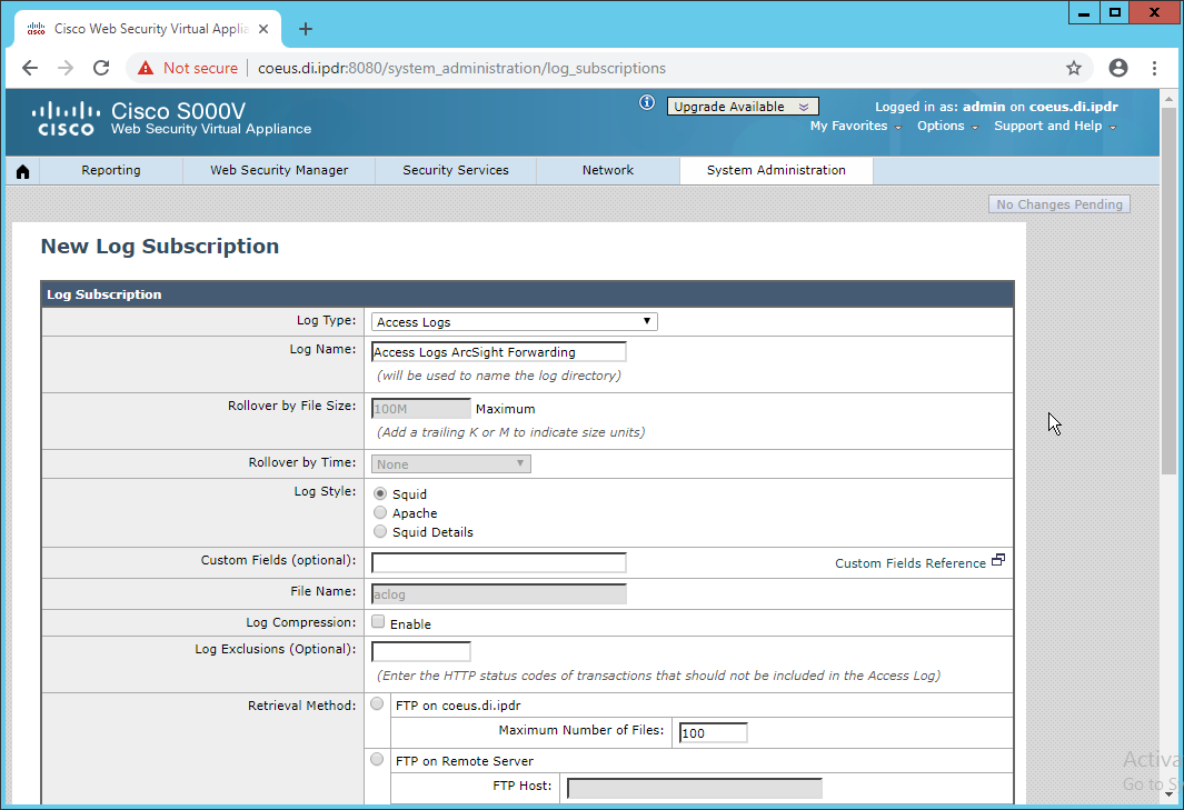
Select Syslog Push.
Enter the hostname of the ArcSight syslog collector server.
Select TCP. (Ensure that your syslog collector server is configured to use TCP.)
Enter 8192 or a custom message-size limit.
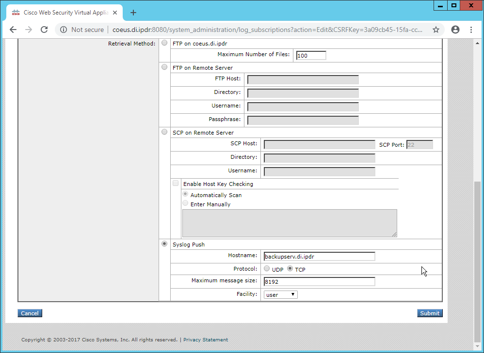
Click Submit.
Click Commit Changes.
Enter a comment if desired.
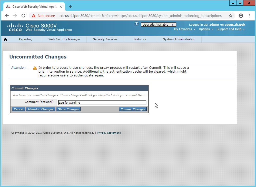
Click Commit Changes. The server will restart, so the web page connection will be temporarily lost.
2.26 Integration: Micro Focus ArcSight and Cisco ISE
This integration briefly details how to send logs to an ArcSight syslog collector from Cisco ISE. Please see Section 2.24 for instructions for setting up an ArcSight syslog collector. If a server is already configured, you do not need to install a new one–simply forward logs to the address of that server.
2.26.1 Configure Cisco ISE to Forward Logs
In the Cisco ISE web client, navigate to Administration > System > Logging > Remote Logging Targets.
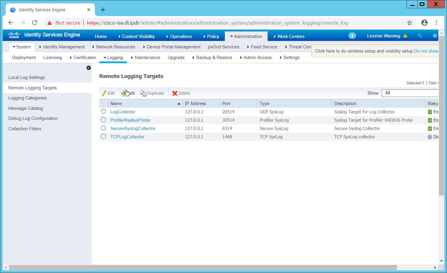
Click Add.
Enter a Name.
Enter the hostname of the ArcSight syslog collector server for Host/IP Address.
Select TCP SysLog for Target Type. (Ensure that your syslog collector server is configured to use TCP.)
Enter 514 or the port used on the syslog server.
Enter 8192 or a custom message-size limit for Maximum Length.
Ensure that Status is set to Enabled.
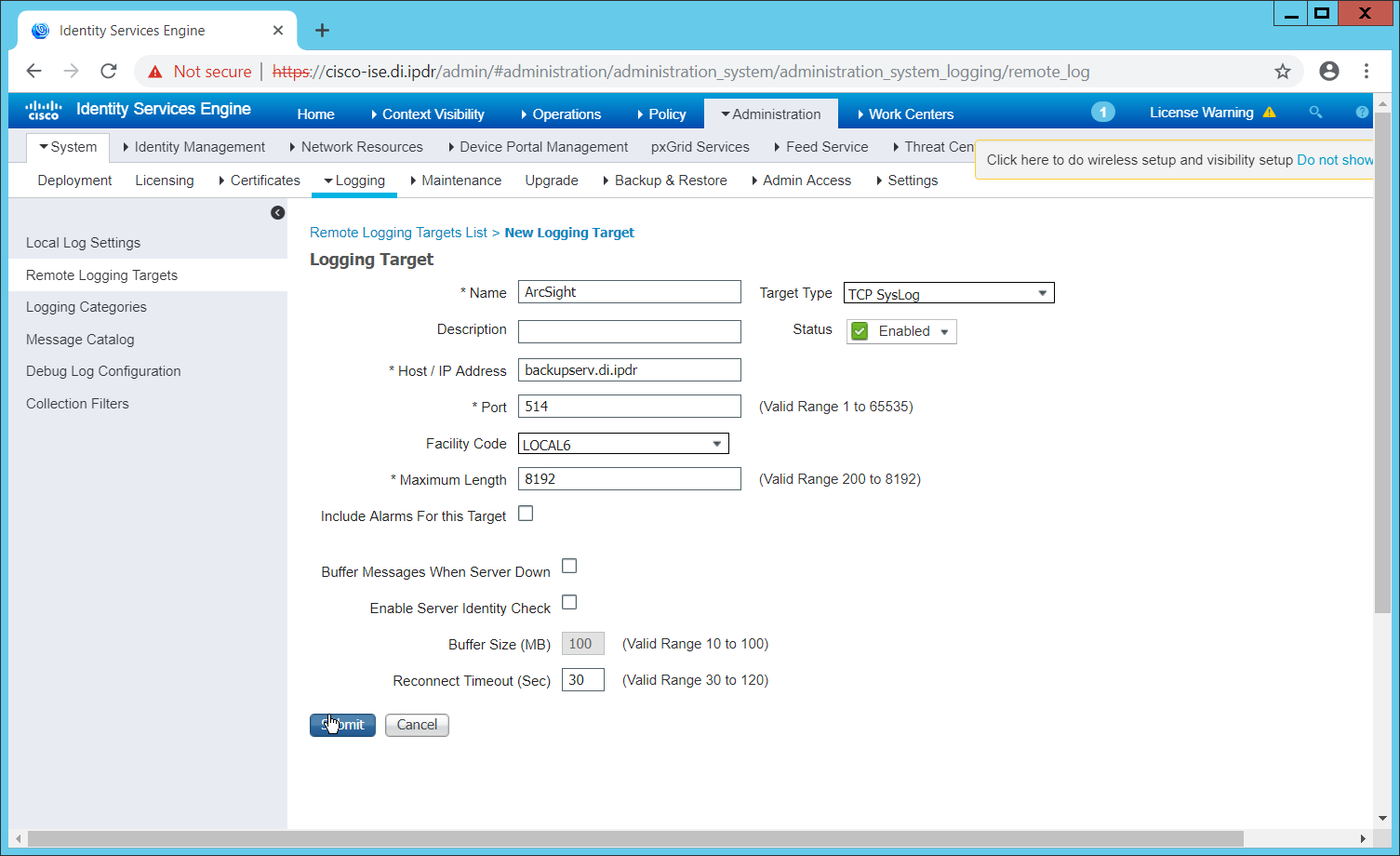
Click Submit.
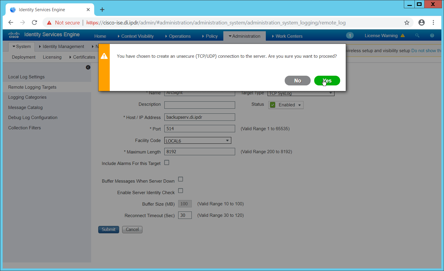
Click Yes.
2.26.2 Select Logs for Forwarding
Navigate to System > Logging > Logging Categories.
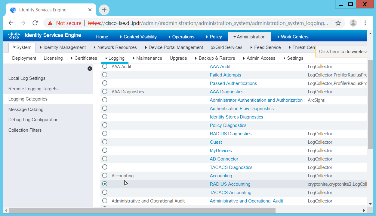
Select a log file to forward to ArcSight.
Click Edit.
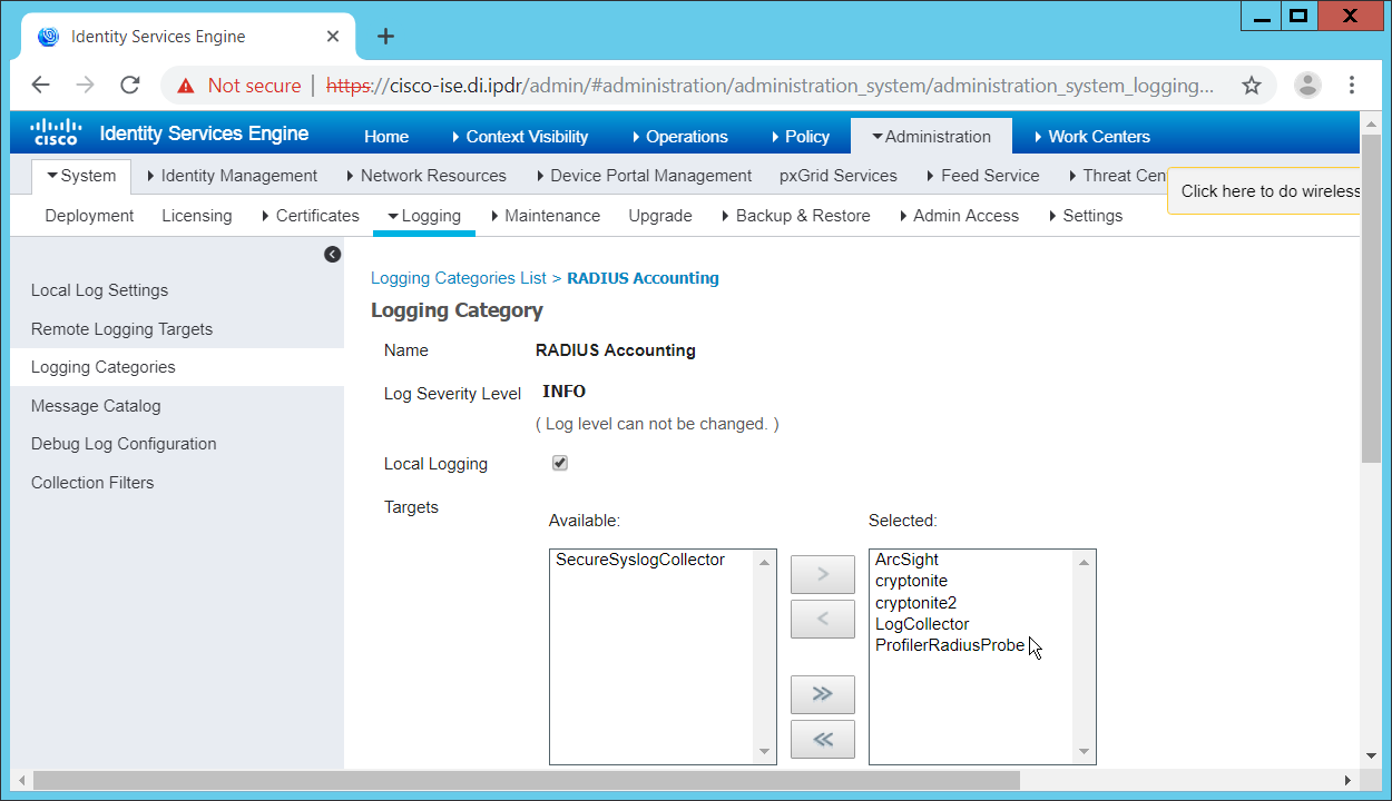
Move the ArcSight logging target you just created to the Selected box.
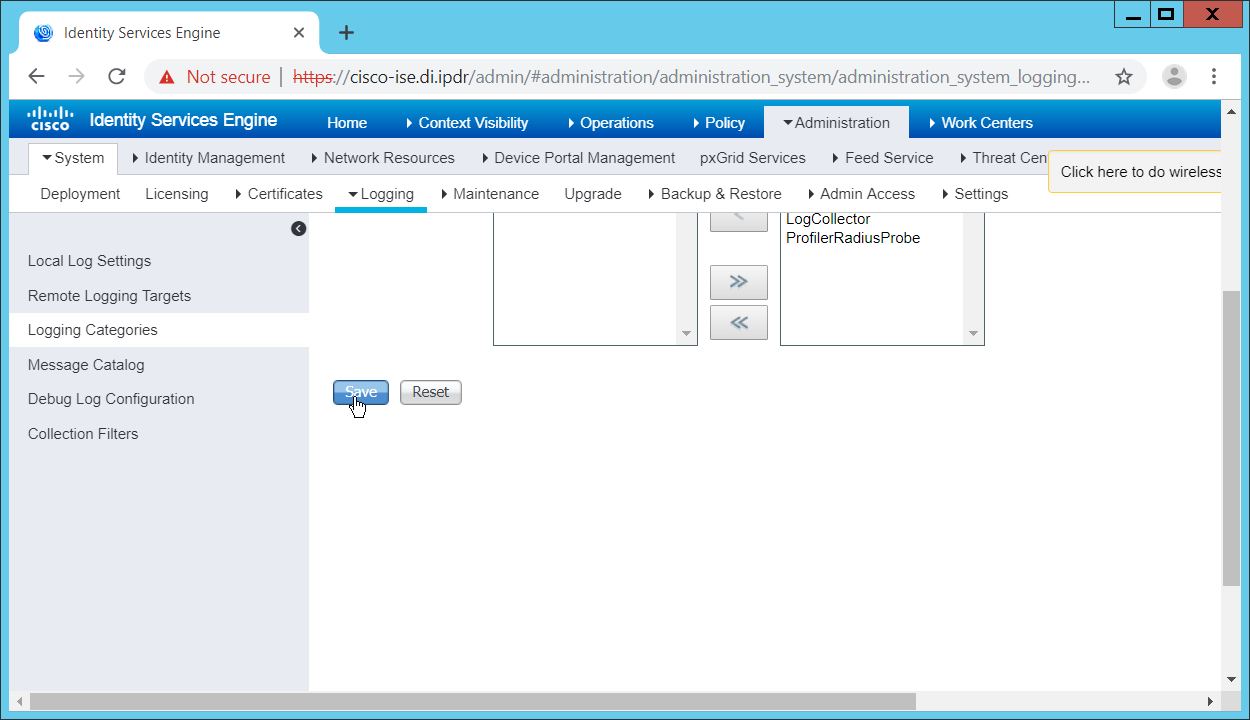
Click Save.
Repeat steps 1–5 for any log files you wish to forward to ArcSight.
2.27 Integration: Micro Focus ArcSight and Symantec DLP
This integration briefly details how to send logs to an ArcSight syslog collector from Symantec DLP. If a server is already configured, you do not need to install a new one–simply forward logs to the address of that server. It is important to note that DLP requires a UDP server, so a TCP syslog server will not work.
2.27.1 Install Micro Focus ArcSight
Run ArcSight-7.9.0.8084.0-Connector-Win64.exe on any server except the one running Cisco Stealthwatch.
Click Next.
Enter C:\Program Files\ArcSightSmartConnectors\WindowsUDP.
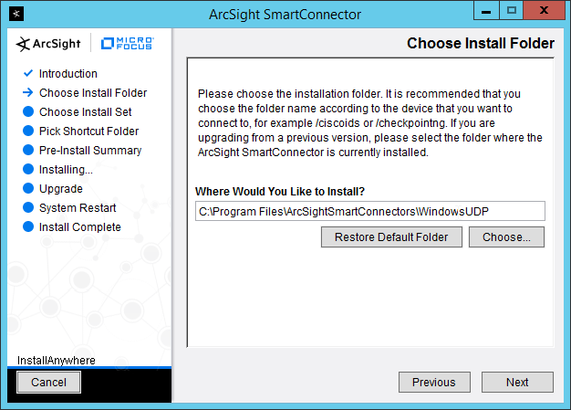
Click Next.

Click Next.
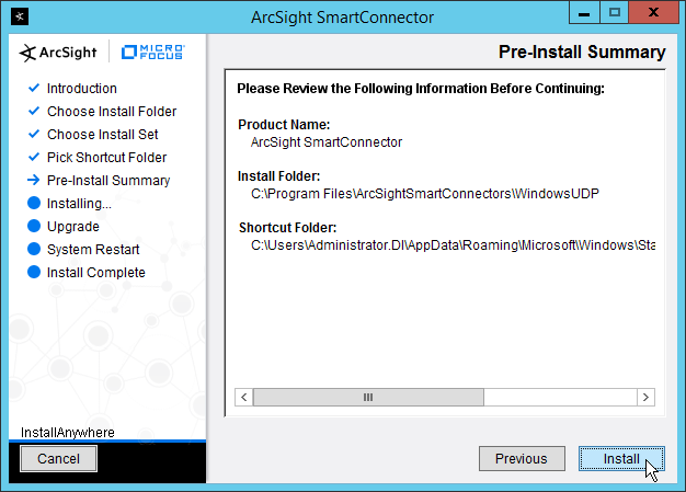
Click Install.
Select Add a Connector.
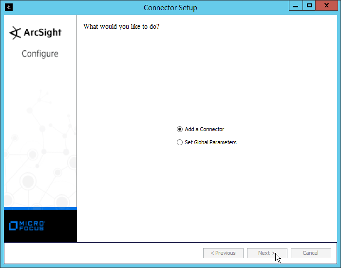
Click Next.
Select Syslog Daemon.

Click Next.
Enter an unused port on which the daemon can run. (Ensure that this port is allowed through the firewall.)
Select UDP for Protocol.

Click Next.
Select ArcSight Manager (encrypted).
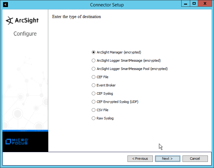
Click Next.
Enter the hostname, port, username, and password for the ArcSight ESM server.
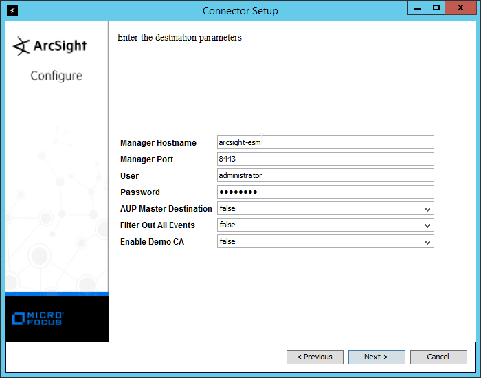
Click Next.
Enter identifying details about the system (only Name is required).

Click Next.
Select Import the certificate to connector from destination.
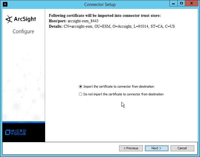
Click Next.

Click Next.
Select Install as a service.

Click Next.
Enter a service name and display name.
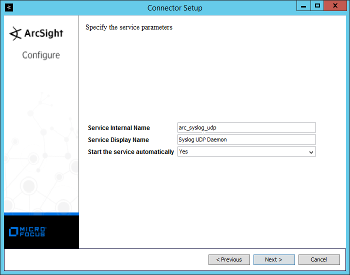
Click Next.
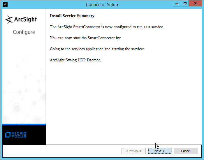
Click Next.
Select Exit.

Click Next.
Click Done.
2.27.2 Configure Symantec DLP to Forward Logs
Log in to the Symantec DLP web console.
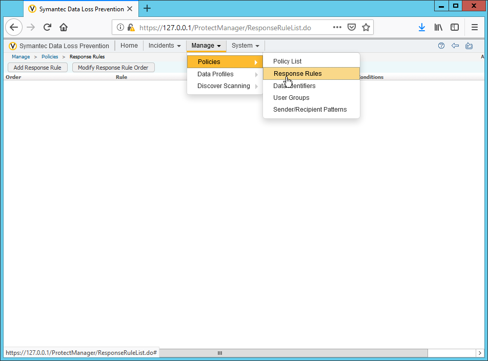
Navigate to Manage > Policies > Response Rules.
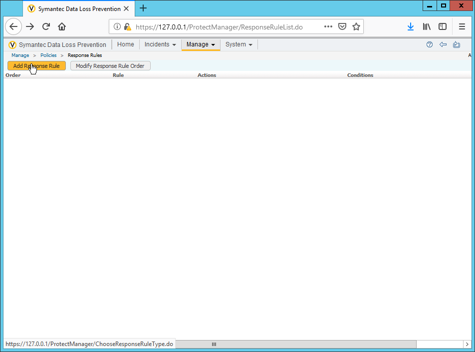
Click Add Response Rule.
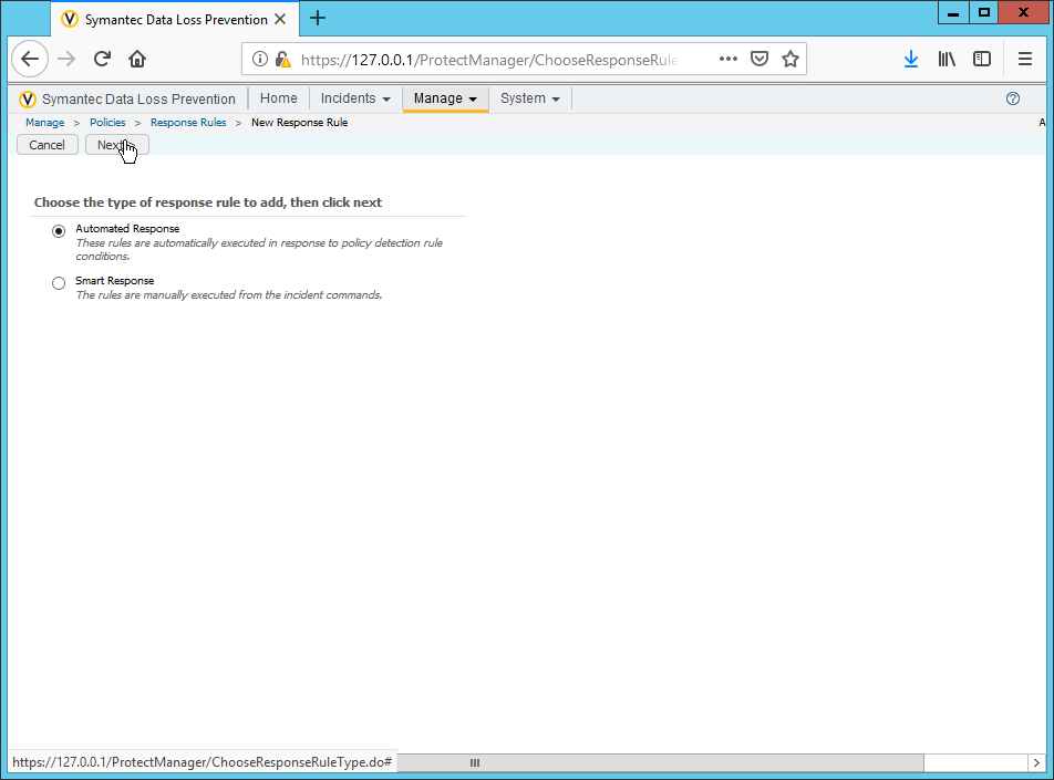
Click Next.
Enter a name for the rule.
Set any conditions for sending syslog messages. If you do not add conditions, all incidents will be forwarded.
Select Log to a Syslog Server for Actions.
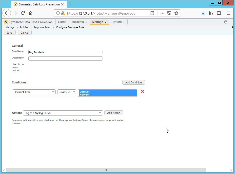
Click Add Action.
Enter the IP address of the ArcSight syslog server.
Enter the port of the ArcSight syslog UDP server.
Select variables and format a log message to include all the information desired to be sent to the ArcSight server. Below is a sample format for the syslog message, which can potentially be parsed according to the needs of your organization.
CEF:0|Symantec|DLP|12.0.1|ruleID|$POLICY$|5|BLOCKED=$BLOCKED$ DATAOWNER_NAME=$DATAOWNER_NAME$ DATAOWNER_EMAIL=$DATAOWNER_EMAIL$
ENDPOINT_DEVICE_ID=$ENDPOINT_DEVICE_ID$ ENDPOINT_MACHINE=$ENDPOINT_MACHINE$ PATH=$PATH$ FILE_NAME=$FILE_NAME$ PARENT_PATH=$PARENT_PATH$
INCIDENT_ID=$INCIDENT_ID$ INCIDENT_SNAPSHOT=$INCIDENT_SNAPSHOT$ MATCH_COUNT=$MATCH_COUNT$ RULES=$RULES$ PROTOCOL=$PROTOCOL$
QUARANTINE_PARENT_PATH=$QUARANTINE_PARENT_PATH$ RECIPIENTS=$RECIPIENTS$ SCAN=$SCAN$ SENDER=$SENDER$ SEVERITY=$SEVERITY$ SUBJECT=$SUBJECT$ TARGET=$TARGET$
FNAME=$ATTACHMENT_NAME$
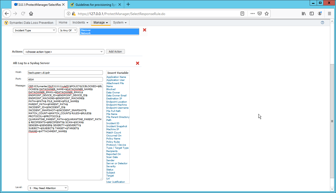
Click Save.
2.28 Integration: Micro Focus ArcSight and CryptoniteNXT
This integration briefly details how to send logs to an ArcSight syslog collector from CryptoniteNXT. Please see Section 2.24 for instructions for setting up an ArcSight syslog collector. If a server is already configured, you do not need to install a new one– simply forward logs to the address of that server. Ensure that you are using a TCP syslog collector. This section assumes that the collector is already under CryponiteNXT’s network protection.
2.28.1 Configure CryptoniteNXT to Forward Logs to ArcSight
Navigate to the Enclave tab in the CryptoniteNXT ACC GUI.
Under SIEM Configuration, check the box next to SIEM is an internal endpoint.
Select the endpoint running the TCP syslog collector.
Enter the port used.
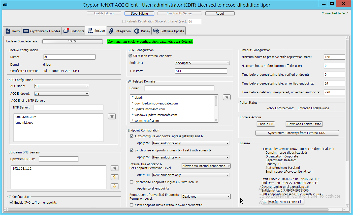
Click Save.
2.29 Integration: Micro Focus ArcSight and Semperis DSP
This integration briefly details how to send logs to an ArcSight syslog collector from Semperis DSP. Please see Section 2.24 for instructions for setting up an ArcSight syslog collector. If a server is already configured, you do not need to install a new one–simply forward logs to the address of that server.
Note: This integration requires Semperis DSP version 2.6.
2.29.1 Configure Semperis DSP to Forward Logs
In Semperis DSP, navigate to Settings > SIEM Integration.
Check the box next to Enable SysLog.
Under Syslog Server, enter the hostname for the ArcSight syslog collector, as well as the port.
Select TCP.
Enter a value for Change Event Polling Frequency based on the needs of your organization– this is how often it will poll for new logs to forward.
Under Change Event Filtering, select AD Changed Items, and Send Operation Log to SysLog. Ensure that All is selected for Partitions.
You can also select any specific operations, classes, and attributes to be forwarded or simply leave as All.
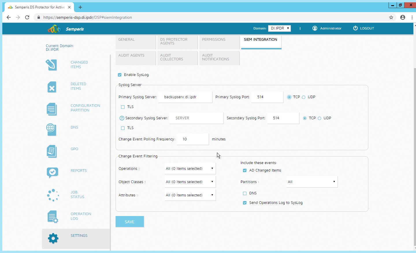
Click Save.
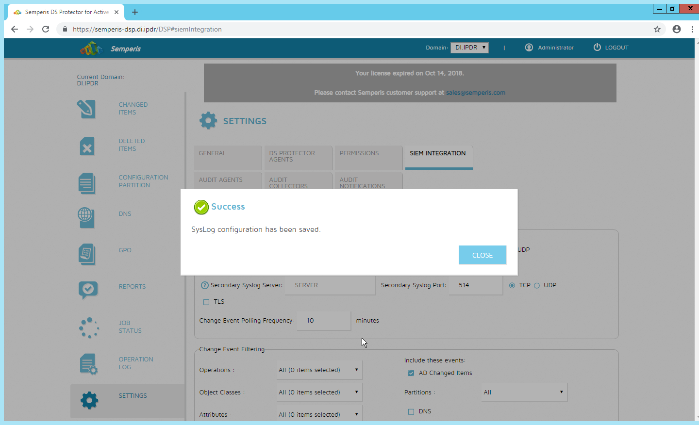
Click Close.
2.30 Integrations: CryptoniteNXT
For the architecture, it is necessary to create the following source groups. If your organization’s desired architecture is different from the one described in this document, it is necessary to adapt the following instructions to avoid loss of network or security function. This section will describe the creation of source groups and destination groups used in this enterprise.
Create the following destination groups and source groups and apply them to the correct endpoints to allow these products and integrations to communicate under CryptoniteNXT.
2.30.1 Active Directory and DNS
This guide assumes the use of Active Directory and DNS on the same Windows 2012 server. The following ports may vary for other products.
Destination Group Name |
Source Group Name |
Protocol |
Port Range |
|---|---|---|---|
ad-dns |
ad-dns-clients |
TCP |
389 |
ad-dns |
ad-dns-clients |
UDP |
389 |
ad-dns |
ad-dns-clients |
UDP |
53 |
ad-dns |
ad-dns-clients |
TCP |
88 |
ad-dns |
ad-dns-clients |
UDP |
88 |
ad-dns |
ad-dns-clients |
TCP |
25 |
ad-dns |
ad-dns-clients |
TCP |
42 |
ad-dns |
ad-dns-clients |
TCP |
137 |
ad-dns |
ad-dns-clients |
TCP |
139 |
ad-dns |
ad-dns-clients |
TCP |
53 |
ad-dns |
ad-dns-clients |
TCP |
636 |
ad-dns |
ad-dns-clients |
TCP |
3268:3269 |
ad-dns |
ad-dns-clients |
TCP |
445 |
ad-dns |
ad-dns-clients |
UDP |
445 |
ad-dns |
ad-dns-clients |
TCP |
9389 |
ad-dns |
ad-dns-clients |
TCP |
5722 |
ad-dns |
ad-dns-clients |
TCP |
464 |
ad-dns |
ad-dns-clients |
UDP |
464 |
ad-dns |
ad-dns-clients |
UDP |
123 |
ad-dns |
ad-dns-clients |
UDP |
137:138 |
ad-dns |
ad-dns-clients |
UDP |
67 |
ad-dns |
ad-dns-clients |
UDP |
2535 |
ad-dns |
ad-dns-clients |
UDP |
49152:65535 |
ad-dns |
ad-dns-clients |
TCP |
49152:65535 |
Endpoint |
Source Groups |
Destination Groups |
|---|---|---|
(all endpoints that need access to AD/DNS) |
ad-dns-clients |
|
AD/DNS server |
ad-dns |
2.30.2 Microsoft Exchange
This guide assumes the use of Microsoft Exchange. The following ports may vary for other products.
Destination Group Name |
Source Group Name |
Protocol |
Port Range |
|---|---|---|---|
exchange |
exchange-clients |
TCP |
443 |
exchange |
exchange-clients |
TCP |
80 |
exchange |
exchange-clients |
TCP |
25 |
exchange |
exchange-clients |
TCP |
379 |
exchange |
exchange-clients |
TCP |
3268:3269 |
exchange |
exchange-clients |
TCP |
636 |
exchange |
exchange-clients |
TCP |
143 |
exchange |
exchange-clients |
TCP |
993 |
exchange |
exchange-clients |
TCP |
110 |
exchange |
exchange-clients |
TCP |
995 |
exchange |
exchange-clients |
TCP |
119 |
exchange |
exchange-clients |
TCP |
563 |
exchange |
exchange-clients |
TCP |
465 |
exchange |
exchange-clients |
TCP |
443691 |
exchange |
exchange-clients |
TCP |
102 |
exchange |
exchange-clients |
TCP |
135 |
exchange |
exchange-clients |
TCP |
389:390 |
exchange |
exchange-clients |
TCP |
53 |
exchange |
exchange-clients |
UDP |
53 |
exchange |
exchange-clients |
TCP |
2525 |
exchange |
exchange-clients |
TCP |
475 |
Endpoint |
Source Groups |
Destination Groups |
|---|---|---|
MS Exchange |
exchange-clients |
exchange |
(all email clients) |
exchange-clients |
|
AD/DNS server |
exchange-clients |
2.30.3 FileZilla
The default port for FileZilla is 21.
To determine the ports being used for your instance, open the FileZilla console.
Navigate to Edit > Settings > General Settings > Listen on these ports, and allow any ports listed here.
If your server listens in passive mode, navigate to Edit > Settings > Passive mode settings > Use custom port range, and allow any ports listed here.
Destination Group Name |
Source Group Name |
Protocol |
Port Range |
|---|---|---|---|
FileZilla |
BackupClients |
TCP |
21 (default–see instructions) |
FileZilla |
BackupClients |
TCP |
51120-511230 (passive mode–see instructions) |
Endpoint |
Source Groups |
Destination Groups |
|---|---|---|
(any endpoints that need to perform backups) |
BackupClients |
|
FileZilla server |
FileZilla |
2.30.4 GreenTec
If GreenTec is configured to use a FileZilla server, refer to the above section. If GreenTec is configured to use Windows Network Share, see below for ports required.
Destination Group Name |
Source Group Name |
Protocol |
Port Range |
|---|---|---|---|
NetworkShare |
GreenTecClients |
TCP |
80 |
NetworkShare |
GreenTecClients |
TCP |
135-139 |
NetworkShare |
GreenTecClients |
TCP |
445 |
Endpoint |
Source Groups |
Destination Groups |
|---|---|---|
(any endpoints that need access to GreenTec disks) |
GreenTecClients |
|
GreenTec server |
NetworkShare |
2.30.5 Tripwire Enterprise
In Tripwire, the Axon Bridge is used for Tripwire Enterprise to contact endpoints. Therefore, the port 5670 must be allowed on endpoints to allow TE to initiate communications. Furthermore, TE requires MSSQL to function, so it must be granted access to that as well.
Destination Group Name |
Source Group Name |
Protocol |
Port Range |
|---|---|---|---|
TripwireEnterprise |
TEClients |
TCP |
443 |
TripwireEnterprise |
TEClients |
TCP |
8080 |
TripwireEnterprise |
TEClients |
TCP |
9898 |
TripwireEnterprise |
TEClients |
TCP |
1169 |
TEAxon |
TripwireE |
TCP |
5670 |
MSSQL |
MSSQLClients |
TCP |
1433 |
Endpoint |
Source Groups |
Destination Groups |
|---|---|---|
(any endpoints that need to be monitored by Tripwire Enterprise) |
TEClients |
TEAxon |
Tripwire Enterprise server |
TripwireE, MSSQLClients |
TripwireEnterprise |
MSSQL server |
MSSQL |
2.30.6 ArcSight ESM
Destination Group Name |
Source Group Name |
Protocol |
Port Range |
|---|---|---|---|
ArcSight |
ArcSightConnectors |
TCP |
8443 |
Endpoint |
Source Groups |
Destination Groups |
|---|---|---|
(any endpoints with an ArcSight Connector installed) |
ArcSightConnectors |
|
ArcSight ESM server |
ArcSight |
2.30.7 Cisco ISE
Please see the CryptoniteNXT Generic RADIUS Integration Guide for instructions on how ISE should be integrated with CryptoniteNXT.
To access the web console for ISE, allow port 443 for any machines that should be able to access the ISE administrative console.
To access the portal for ISE, allow port 8443 (default) for any machines that will need to access the portal. You can find this value by looking at your portal configuration in ISE.
Furthermore, if RADIUS is configured for the posture integration, you will need to add any ports used in RADIUS for both ISE and the internal switch. The default for these is 1812 (Authentication), 1813 (Accounting), and 1700 (CoA). RADIUS can be TCP or UDP, so you can restrict this to your organization’s configuration.
Destination Group Name |
Source Group Name |
Protocol |
Port Range |
|---|---|---|---|
ISE |
ISEConsole |
TCP |
443 |
ISE |
ISEClients |
TCP |
8443 |
radius |
ISESwitch, ISEServer |
TCP |
1812 |
radius |
ISESwitch, ISEServer |
UDP |
1812 |
radius |
ISESwitch, ISEServer |
TCP |
1813 |
radius |
ISESwitch, ISEServer |
UDP |
1813 |
radius |
ISESwitch, ISEServer |
TCP |
1700 |
radius |
ISESwitch, ISEServer |
UDP |
1700 |
Endpoint |
Source Groups |
Destination Groups |
|---|---|---|
(any endpoints that need to do posture under ISE) |
ISEClients |
|
(any endpoints that need to access the ISE web console) |
ISEConsole |
|
ISE server |
ISEServer |
ISE, radius |
(internal switches or RADIUS servers used for ISE Posture) |
ISESwitch, ISEClients |
radius |
Cryptonite ACC Node |
radius |
2.30.8 Semperis DSP
Semperis DSP recommends allowing full network access during the initial database sync. After that, the following ports should be left open for communication.
Destination Group Name |
Source Group Name |
Protocol |
Port Range |
|---|---|---|---|
dsp |
dsp-admin |
TCP |
443 |
dsp |
dsp-agents |
TCP |
8903 |
dsp |
dsp-agents |
TCP |
135 |
dsp |
dsp-agents |
TCP |
445 |
dsp |
dsp-agents |
TCP |
1024:1034 |
ad-dsp |
dsp-client |
TCP |
8772 |
ad-dsp |
dsp-client |
TCP |
8750 |
ad-dsp |
dsp-client |
ICMP |
0:255 |
Endpoint |
Source Groups |
Destination Groups |
|---|---|---|
(any endpoints that need admin access to DSP) |
dsp-admin |
|
Semperis DSP |
ad-dns-clients, dsp-client, exchange-clients |
dsp |
Active Directory server |
dsp-agents |
ad-dsp |
2.30.9 Symantec DLP
This largely depends on how distributed the setup of DLP is. See here for a list of ports required by Symantec DLP: https://support.symantec.com/us/en/article.tech220846.html.
For this build, we used a single server that contained the database, so only the agents and administrative clients needed to be allowed to communicate through Cryptonite.
Destination Group Name |
Source Group Name |
Protocol |
Port Range |
|---|---|---|---|
dlp |
dlp-admin |
TCP |
443 |
dlp |
dlp-clients |
TCP |
10443 |
2.30.10 Cisco WSA
WSA uses a proprietary command line, which means it does not have a way of authenticating to the CryptoniteNXT portal. For devices such as this, there are two options.
The device can be left outside CryptoniteNXT.
The device can be placed under CryptoniteNXT on a CryptoniteNXT Endpoint Node with the portal disabled.
To prevent MAC spoofing, by default Cryptonite pins MAC addresses to the port + VLAN (Virtual LAN) to which a device is connected, so a malicious device connecting to the end-point node with the same MAC as an already connected IP360 would still be required to authenticate. Physical security for the end-point node can further mitigate concerns about MAC spoofing.
If you can find a way to authenticate WSA to CryptoniteNXT or decide to use the disabled portal option with strong physical security, we provide the ports below for integration.
To access the web console for WSA, allow port 8080 for any machines that should be able to access the ISE administrative console.
To access the proxy, allow port 80 and port 3128 for any machines that will need to go through the proxy, which will likely be most clients in the enterprise. Port 80 is for the wpad.dat file, and port 3128 is for the proxy itself.
Destination Group Name |
Source Group Name |
Protocol |
Port Range |
|---|---|---|---|
wsa |
wsa-clients |
TCP |
80 |
wsa |
wsa-clients |
TCP |
3128 |
wsa |
wsa-admin |
TCP |
8080 |
Endpoint |
Source Groups |
Destination Groups |
|---|---|---|
(any endpoints that need to use the proxy to connect to the internet) |
wsa-clients |
|
(any endpoints that need to access the WSA web console) |
wsa-admin |
|
Cisco WSA |
wsa |
2.30.11 Tripwire IP360
IP360 uses a proprietary command line, which means it does not have a way of authenticating to the CryptoniteNXT portal. For devices such as this, there are two options.
The device can be left outside CryptoniteNXT.
The device can be placed under CryptoniteNXT on a CryptoniteNXT Endpoint Node with the portal disabled.
To prevent MAC spoofing, by default Cryptonite pins MAC addresses to the port+VLAN to which a device is connected, so a malicious device connecting to the end-point node with the same MAC as an already connected IP360 would still be required to authenticate. Physical security for the end-point node can further mitigate concerns about MAC spoofing.
If you can find a way to authenticate IP360 to CryptoniteNXT or decide to use the disabled portal option with strong physical security, we provide the ports below for integration.
To access the web console for IP360, allow port 443 for any machines that should be able to access the IP360 administrative console.
IP360 should have access to all ports of the client machines it needs to scan. Another option is to simply add IP360 to all the source groups present in your enterprise, and it will give an overview of the vulnerabilities of clients on ports that CryptoniteNXT is not actively protecting. Alternatively, you can disable policy enforcement temporarily on the CryptoniteNXT Endpoint Node to which IP360 is connected, but you should do this only during scans.
Destination Group Name |
Source Group Name |
Protocol |
Port Range |
|---|---|---|---|
ip360 |
ip360admin |
TCP |
443 |
scantarget |
ip360scanner |
TCP |
1:65535 |
scantarget |
ip360scanner |
UDP |
1:65535 |
scantarget |
ip360scsanner |
ICMP |
0:255 |
Endpoint |
Source Groups |
Destination Groups |
|---|---|---|
(any endpoints need to access the IP360 web console) |
ip360admin |
|
(any endpoints to be fully scanned by IP360) |
scantarget |
|
IP360 |
ip360scanner |
ip360 |
2.30.11.1 Tripwire Log Center, Tripwire IP360, Tripwire Enterprise, and ArcSight ESM
The guide details an integration among Tripwire IP360, Tripwire Enterprise, Tripwire Log Center, and ArcSight ESM. This section describes the ports needed to allow the integrations through Cryptonite.
First, traffic must be allowed from Tripwire Log Center to the MSSQL server. To do this, ensure that Tripwire Log Center can access 1433 on the MSSQL server. (Note: Tripwire Enterprise also has access to this port, as described above in the Tripwire Enterprise section.)
Then traffic from Tripwire Enterprise to Tripwire Log Center should be allowed on ports 8091 and 1468.
Traffic from IP360 to Tripwire Log Center should be allowed on port 22 for the SFTP (Secure FTP) transfer. Also, traffic from Tripwire Log Center to 5670 on Tripwire IP360 should be allowed. If you chose to leave IP360 out of the Cryptonite NXT enclave, Tripwire Log Center will need to be able to reach it externally.
Traffic from Tripwire Log Center to the machine containing the ArcSight TCP syslog container should be allowed on the port configured (in the guide, we use port 514). As a last note, the server running the ArcSight syslog connector requires an IP and not a hostname for its integration with Tripwire Log Center–you must set a static IP for the connector server in Cryptonite and enter this IP in the appropriate place in Tripwire Log Center’s configuration.
Destination Group Name |
Source Group Name |
Protocol |
Port Range |
|---|---|---|---|
MSSQL |
MSSQLClients |
TCP |
1443 |
TLC |
TLCClients |
TCP |
8091 |
TLC |
TLCClients |
TCP |
1468 |
TLC |
TLCClients |
TCP |
22 |
ArcSightTCPSysConn |
TCPSysClients |
TCP |
514 |
ip360 |
ip360admin |
TCP |
5670 |
Endpoint |
Source Groups |
Destination Groups |
|---|---|---|
Tripwire Log Center |
TCPSysClients, MSSQLClients, ip360admin |
TLC |
Tripwire Enterprise |
TLCClients |
|
(server running ArcSight TCP syslog connector) |
ArcSightTCPSysConn |
|
MSSQL |
MSSQL |
|
IP360 |
TLCClients |
ip360 |
2.30.12 FileZilla and ArcSight
The guide details an integration between FileZilla and ArcSight ESM to forward logs from FileZilla to ArcSight. This section describes the ports needed to allow the integrations through Cryptonite.
Because this integration involves the use of an ArcSight Connector directly on the FileZilla server, only one port is needed. The FileZilla server should be able to directly communicate with 8443 on the ArcSight ESM server.
Destination Group Name |
Source Group Name |
Protocol |
Port Range |
|---|---|---|---|
ArcSight |
ArcSightConnectors |
TCP |
8443 |
Endpoint |
Source Groups |
Destination Groups |
|---|---|---|
FileZilla |
ArcSightConnectors |
|
ArcSight ESM |
ArcSight |
2.30.13 Cisco ISE and ArcSight
The guide details an integration between Cisco ISE and ArcSight ESM to forward logs from ISE to ArcSight. This section describes the ports needed to allow the integrations through Cryptonite.
Traffic from Cisco ISE to the machine containing the ArcSight TCP syslog container should be allowed on the port configured (in the guide, we use port 514).
Destination Group Name |
Source Group Name |
Protocol |
Port Range |
|---|---|---|---|
ArcSightTCPSysConn |
TCPSysClients |
TCP |
514 |
Endpoint |
Source Groups |
Destination Groups |
|---|---|---|
Cisco ISE |
TCPSysClients |
|
(server running ArcSight TCP syslog connector) |
ArcSightTCPSysConn |
2.30.14 Cisco WSA and ArcSight
The guide details an integration between Cisco WSA and ArcSight ESM to forward logs from WSA to ArcSight. This section describes the ports needed to allow the integrations through Cryptonite.
Traffic from Cisco WSA to the machine containing the ArcSight TCP syslog container should be allowed on the port configured (in the guide, we use port 514).
Destination Group Name |
Source Group Name |
Protocol |
Port Range |
|---|---|---|---|
ArcSightTCPSysConn |
TCPSysClients |
TCP |
514 |
Endpoint |
Source Groups |
Destination Groups |
|---|---|---|
Cisco WSA |
TCPSysClients |
|
(server running ArcSight TCP syslog connector) |
ArcSightTCPSysConn |
2.30.15 Semperis DSP and ArcSight
The guide details an integration between Semperis DSP and ArcSight ESM to forward logs from DSP to ArcSight. This section describes the ports needed to allow the integrations through Cryptonite.
Traffic from Semperis DSP to the machine containing the ArcSight TCP syslog container should be allowed on the port configured (in the guide, we use port 514).
Destination Group Name |
Source Group Name |
Protocol |
Port Range |
|---|---|---|---|
ArcSightTCPSysConn |
TCPSysClients |
TCP |
514 |
Endpoint |
Source Groups |
Destination Groups |
|---|---|---|
Semperis DSP |
TCPSysClients |
|
(server running ArcSight TCP syslog connector) |
ArcSightTCPSysConn |
2.30.16 Symantec DLP and ArcSight
The guide details an integration between Symantec DLP and ArcSight ESM to forward logs from DLP to ArcSight. This section describes the ports needed to allow the integrations through Cryptonite.
Traffic from Symantec DLP to the machine containing the ArcSight UDP syslog container should be allowed on the port configured (in the guide, we use UDP and port 6514).
Destination Group Name |
Source Group Name |
Protocol |
Port Range |
|---|---|---|---|
ArcSightTCPSysConn |
TCPSysClients |
UDP |
6514 |
Endpoint |
Source Groups |
Destination Groups |
|---|---|---|
Symantec DLP |
TCPSysClients |
|
(server running ArcSight TCP syslog connector) |
ArcSightTCPSysConn |