NIST SPECIAL PUBLICATION 1800-16D
Securing Web Transactions
TLS Server Certificate Management
Volume D:
How-To Guides
Murugiah Souppaya
NIST
Mehwish Akram
Brandon Everhart
Brian Johnson
Brett Pleasant
Susan Symington
The MITRE Corporation
William C. Barker
Strativia
Paul Turner
Venafi
Clint Wilson
DigiCert
Dung Lam
F5
Alexandros Kapasouris
Symantec
Rob Clatterbuck
Jane Gilbert
Thales Trusted Cyber Technologies
June 2020
Final
This publication is available free of charge from: http://doi.org/10.6028/NIST.SP.1800-16
The first draft of this publication is available free of charge from: https://www.nccoe.nist.gov/projects/building-blocks/tls-server-certificate-management

DISCLAIMER
Certain commercial entities, equipment, products, or materials may be identified by name or company logo or other insignia in order to acknowledge their participation in this collaboration or to describe an experimental procedure or concept adequately. Such identification is not intended to imply special status or relationship with NIST or recommendation or endorsement by NIST or NCCoE; neither is it intended to imply that the entities, equipment, products, or materials are necessarily the best available for the purpose.
National Institute of Standards and Technology Special Publication 1800-16D Natl. Inst. Stand. Technol. Spec. Publ. 1800-16D, 223 pages, (June 2020), CODEN: NSPUE2
FEEDBACK
As a private-public partnership, we are always seeking feedback on our practice guides. We are particularly interested in seeing how businesses apply NCCoE reference designs in the real world. If you have implemented the reference design, or have questions about applying it in your environment, please email us at tls-cert-mgmt-nccoe@nist.gov.
All comments are subject to release under the Freedom of Information Act.
NATIONAL CYBERSECURITY CENTER OF EXCELLENCE
The National Cybersecurity Center of Excellence (NCCoE), a part of the National Institute of Standards and Technology (NIST), is a collaborative hub where industry organizations, government agencies, and academic institutions work together to address businesses’ most pressing cybersecurity issues. This public-private partnership enables the creation of practical cybersecurity solutions for specific industries, as well as for broad, cross-sector technology challenges. Through consortia under Cooperative Research and Development Agreements (CRADAs), including technology partners—from Fortune 50 market leaders to smaller companies specializing in information technology security—the NCCoE applies standards and best practices to develop modular, easily adaptable example cybersecurity solutions using commercially available technology. The NCCoE documents these example solutions in the NIST Special Publication 1800 series, which maps capabilities to the NIST Cybersecurity Framework and details the steps needed for another entity to re-create the example solution. The NCCoE was established in 2012 by NIST in partnership with the State of Maryland and Montgomery County, Maryland.
NIST CYBERSECURITY PRACTICE GUIDES
NIST Cybersecurity Practice Guides (Special Publication 1800 series) target specific cybersecurity challenges in the public and private sectors. They are practical, user-friendly guides that facilitate the adoption of standards-based approaches to cybersecurity. They show members of the information security community how to implement example solutions that help them align more easily with relevant standards and best practices, and provide users with the materials lists, configuration files, and other information they need to implement a similar approach.
The documents in this series describe example implementations of cybersecurity practices that businesses and other organizations may voluntarily adopt. These documents do not describe regulations or mandatory practices, nor do they carry statutory authority.
ABSTRACT
Transport Layer Security (TLS) server certificates [D4], [D5] are critical to the security of both internet-facing and private web services. A large- or medium-scale enterprise may have thousands or even tens of thousands of such certificates, each identifying a specific server in its environment. Despite the critical importance of these certificates, many organizations lack a formal TLS certificate management program, and the ability to centrally monitor and manage their certificates. Instead, certificate management tends to be spread across each of the different groups responsible for the various servers and systems in an organization. Central security teams struggle to ensure certificates are being properly managed by each of these disparate groups. Where there is no central certificate management service, the organization is at risk, because once certificates are deployed, current inventories must be maintained to support regular monitoring and certificate maintenance. Organizations that do not properly manage their certificates face significant risks to their core operations, including:
Despite the mission-critical nature of TLS server certificates, many organizations have not defined the clear policies, processes, roles, and responsibilities needed for effective certificate management. Moreover, many organizations do not leverage available automation tools to support effective management of the ever-growing numbers of certificates. The consequence is continuing susceptibility to security incidents.
This NIST Cybersecurity Practice Guide shows large and medium enterprises how to employ a formal TLS certificate management program to address certificate-based risks and challenges. It describes the TLS certificate management challenges faced by organizations; provides recommended best practices for large-scale TLS server certificate management; describes an automated proof-of-concept implementation that demonstrates how to prevent, detect, and recover from certificate-related incidents; and provides a mapping of the demonstrated capabilities to the recommended best practices and to NIST security guidelines and frameworks.
The solutions and architectures presented in this practice guide are built upon standards-based, commercially available, and open-source products. These solutions can be used by any organization managing TLS server certificates. Interoperable solutions are provided that are available from different types of sources (e.g., both commercial and open-source products).
KEYWORDS
Authentication; certificate; cryptography; identity; key; key management; PKI; private key; public key; public key infrastructure; server; signature; TLS; Transport Layer Security
DOCUMENT CONVENTIONS
The terms “shall” and “shall not” indicate requirements to be followed strictly in order to conform to the publication and from which no deviation is permitted.
The terms “should” and “should not” indicate that among several possibilities, one is recommended as particularly suitable, without mentioning or excluding others, or that a certain course of action is preferred but not necessarily required, or that (in the negative form) a certain possibility or course of action is discouraged but not prohibited.
The terms “may” and “need not” indicate a course of action permissible within the limits of the publication.
The terms “can” and “cannot” indicate a possibility and capability, whether material, physical, or causal.
CALL FOR PATENT CLAIMS
This public review includes a call for information on essential patent claims (claims whose use would be required for compliance with the guidance or requirements in this Information Technology Laboratory [ITL] publication). Such guidance and/or requirements may be directly stated in this ITL Publication or by reference to another publication. This call also includes disclosure, where known, of the existence of pending U.S. or foreign patent applications relating to this ITL publication and of any relevant unexpired U.S. or foreign patents.
ITL may require from the patent holder, or a party authorized to make assurances on its behalf, in written or electronic form, either:
a) assurance in the form of a general disclaimer to the effect that such party does not hold and does not currently intend holding any essential patent claim(s); or
b) assurance that a license to such essential patent claim(s) will be made available to applicants desiring to utilize the license for the purpose of complying with the guidance or requirements in this ITL publication either:
i) under reasonable terms and conditions that are demonstrably free of any unfair discrimination; orii) without compensation and under reasonable terms and conditions that are demonstrably free of any unfair discrimination.
Such assurance shall indicate that the patent holder (or third party authorized to make assurances on its behalf) will include in any documents transferring ownership of patents subject to the assurance, provisions sufficient to ensure that the commitments in the assurance are binding on the transferee, and that the transferee will similarly include appropriate provisions in the event of future transfers with the goal of binding each successor-in-interest.
The assurance shall also indicate that it is intended to be binding on successors-in-interest regardless of whether such provisions are included in the relevant transfer documents.
Such statements should be addressed to tls-cert-mgmt-nccoe@nist.gov.
ACKNOWLEDGMENTS
We are grateful to the following individuals for their generous contributions of expertise and time.
Name |
Organization |
|---|---|
Dean Coclin |
DigiCert |
Tim Hollebeek |
DigiCert |
Robert Smith |
F5 |
Nancy Correll |
The MITRE Corporation |
Mary Raguso |
The MITRE Corporation |
Aaron Aubrecht |
Venafi |
Justin Hansen |
Venafi |
The Technology Partners/Collaborators who participated in this build submitted their capabilities in response to a notice in the Federal Register. Respondents with relevant capabilities or product components were invited to sign a Cooperative Research and Development Agreement (CRADA) with NIST, allowing them to participate in a consortium to build this example solution. We worked with:
Technology Partner/Collaborator |
Build Involvement |
|---|---|
DigiCert |
External Certificate Authority and CertCentral console |
F5 |
BIG-IP Local Traffic Manager load balancer |
Thales TCT |
Luna SA 1700 Hardware Security Module |
Symantec |
SSL Visibility Appliance for TLS interception and inspection |
Venafi |
Trust Protection Platform (TLS certificate manager, log server, and scanning tool) |
List of Figures
Figure 1‑1 TLS Server Certificate Management Example Implementation: Logical Architecture
Figure 1‑2 TLS Server Certificate Management Example Implementation: Laboratory Configuration
Figure 1‑3 TLS Lab Logging Infrastructure
Figure 2‑1 Overview of Dependencies Among Components Deployed for the Example Build
Figure 2‑2 Venafi Dashboard Expiration Widget showing the Certificate Expiration Profile
List of Tables
Table 1‑1 Naming and Addressing Information for all Microsoft Windows Servers
Table 1‑2 Naming and Addressing Information for all Microsoft Windows 10 Workstations
Table 1‑3 Naming and Addressing Information for All Fedora-Based Systems
Table 1‑4 Naming and Addressing Information for All CentOS Servers
1 Introduction
Organizations that improperly manage their Transport Layer Security (TLS) server certificates [D4], [D5] risk system outages and security breaches, which can result in revenue loss, harm to reputation, and exposure of confidential data to attackers. TLS is the most widely used protocol for securing web transactions and other communications on internal networks and the internet. TLS certificates are central to the operation and security of internet-facing and private web services. Some organizations have tens of thousands of TLS certificates and keys requiring ongoing maintenance and management.
The National Cybersecurity Center of Excellence (NCCoE) at the National Institute of Standards and Technology (NIST) built a laboratory environment to demonstrate how large and medium enterprises can better manage TLS server certificates in the following ways:
defining operational and security policies and identifying roles and responsibilities
establishing comprehensive certificate inventories and ownership tracking
conducting continuous monitoring of the certificate operation and security status
automating certificate management to minimize human error and maximize efficiency on a large scale
enabling rapid migration to new certificates and keys as needed in response to certificate authority (CA) compromise or discovery of vulnerabilities in cryptographic algorithms or libraries
The following volumes of this guide show information technology (IT) professionals and security engineers how we implemented this example solution. We cover all the products employed in this reference design. We do not re-create the product manufacturers’ documentation, which is presumed to be widely available. Rather, these volumes show how we incorporated the products together in our environment.
Note: These are not comprehensive tutorials. There are many possible service and security configurations for these products that are out of scope for this reference design.
1.1 Practice Guide Structure
This National Institute of Standards and Technology (NIST) Cybersecurity Practice Guide demonstrates a standards-based reference design and provides users with the information they need to replicate automated management of TLS server certificates. This reference design is modular and can be deployed in whole or in part.
This guide contains four volumes:
NIST SP 1800-16A: Executive Summary
NIST SP 1800-16B: Security Risks and Recommended Best Practices
NIST SP 1800-16C: Approach, Architecture, and Security Characteristics–what we built and why
NIST SP 1800-16D: How-To Guides—instructions for building the example solution (you are here)
Depending on your role in your organization, you might use this guide in different ways:
Business decision makers, including chief security and technology officers, will be interested in the Executive Summary, NIST SP 1800-16A, which describes the following topics:
recommendations for TLS server certificate management
challenges that enterprises face in proper deployment, management, and use of TLS
example solution built at the NCCoE
You might share the Executive Summary, NIST SP 1800-16A, with your leadership team members to help them understand the importance of adopting standards-based TLS server certificate management.
Senior information technology and security officers will be informed by NIST SP 1800-16B, which describes the:
TLS server certificate infrastructure and management processes
risks associated with mismanagement of certificates
organizational challenges associated with server certificate management
recommended best practices for server certificate management
recommendations for implementing a successful certificate management program
mapping of best practices for TLS server certificate management to the NIST Framework for Improving Critical Infrastructure Cybersecurity (Cybersecurity Framework) [D4]
application of specific controls defined within NIST Special Publication (SP) 800-53 [D4] to the TLS server certificate management recommended best practices
Technology or security program managers who are concerned with how to identify, understand, assess, and mitigate risk will be interested in NIST SP 1800-16C, which describes what we did and why. The following sections will be of particular interest:
Section 3.4.1, Threats, Vulnerabilities and Risks, provides a description of the risk analysis we performed.
Section 3.4.2, Security Categorization and SP 800-53 Controls [D4], lists the security controls assigned to address TLS server certificate risks.
Section 3.4.3, Security Control Map, maps the security characteristics of this example solution to cybersecurity standards and best practices.
IT professionals who want to implement such an approach will find this whole practice guide useful. You can use this How-To portion of the guide, NIST SP 1800-16D, to replicate all or parts of the build created in our lab. This How-To portion of the guide provides specific product installation, configuration, and integration instructions for implementing the example solution. We do not re-create the product manufacturers’ documentation, which is generally widely available. Rather, we show how we incorporated the products together in our environment to create an example solution.
This guide assumes that IT professionals have experience implementing security products within the enterprise. While we have used a suite of commercial and open source products to address this challenge, this guide does not endorse these particular products. Your organization can adopt this solution or one that adheres to these guidelines in whole, or you can use this guide as a starting point for tailoring and implementing parts of providing automation support for TLS server certificate management. Your organization’s security experts should identify the products that will best integrate with your existing tools and IT system infrastructure. We hope that you will seek products that are congruent with applicable standards and best practices. Section 1.3, Build Architecture Summary, lists the products that we used and maps them to the cybersecurity controls provided by this reference solution.
A NIST Cybersecurity Practice Guide does not describe “the” solution, but a possible solution. We seek feedback on its contents and welcome your input. Comments, suggestions, and success stories will improve subsequent versions of this guide. Please contribute your thoughts to tls-cert-mgmt-nccoe@nist.gov.
1.2 Build Overview
This NIST Cybersecurity Practice Guide addresses the use of commercially available technologies to develop an example implementation for managing TLS server certificates. This project focuses on certificate management in medium and large enterprises that rely on TLS to secure customer-facing and internal applications. The example implementation developed in this project demonstrates how to manage TLS server certificates to reduce outages, improve security, and enable disaster recovery activities. It shows how to establish, assign, change, and track an inventory of TLS certificates; automate management of TLS certificates; perform continuous monitoring of TLS certificates; perform large-scale replacement of certificates that are not trusted; log all certificate and private-key management operations; manage certificates and keys on proxy servers, load balancers, and inspection appliances; and use a Hardware Security Module (HSM). The HSM can securely generate, store, manage, and use private keys corresponding to TLS server certificates, the signing keys of internal certificate authorities (CAs), and symmetric keys that must be kept secret.
1.2.1 Usage Scenarios
The example implementation fulfills the following use cases:
building and maintaining inventory of the enterprise’s deployed TLS server certificates
automating management of those certificates, including use of an external CA and protection of private keys and other secrets by using an HSM
continuously monitoring the certificates for validity
supporting disaster recovery by quickly replacing a large number of certificates
logging all certificate and private-key management operations
for those enterprises with a policy to perform passive inspection, copying private keys from several different TLS servers to the TLS inspection appliance
1.2.1.1 Building the Inventory
The example implementation demonstrates the ability to establish and maintain a systematized inventory of certificates (and keys) in use on the network. It enables a user to discover certificates not currently being managed by the inventory, efficiently enroll and provision new certificates (and keys), store relevant information with those certificates, and discover the absence of an expected certificate from a machine where it should be installed. It also enables certificates to be revoked and to change the owner associated with a certificate, as needed.
1.2.1.2 Automation
The example implementation demonstrates the ability to automatically enroll and provision a new certificate and can replace a certificate approaching expiration. Automated certificate management is demonstrated on various enterprise systems, including load balancers acting as TLS proxies that use remote agentless management, web servers with remote agentless management, web servers using the Automatic Certificate Management Environment (ACME) protocol, and servers that are deployed via development operations (DevOps) technologies by using a certificate management plug-in to the DevOps framework. In conjunction with the demonstration of ACME, HSM is used to securely generate, store, manage, and process the cryptographic key pairs for one TLS server. Remote agentless management was used to automate management of the certificates and keys for this system. In the current effort the NCCoE undertook only a limited demonstration. This limited demonstration employed Kubernetes in a cloud environment where DevOps frameworks are commonly used.
1.2.1.3 Continuous Monitoring
The example implementation demonstrates the ability to continuously monitor TLS certificates (and keys) managed by the inventory system and can act upon the status of any certificate (e.g., report the status of or replace a certificate that has expired, is about to expire, or does not conform to policy). It can send periodic expiration reports to certificate owners to show which of their certificates are nearing expiration, and a variety of notifications and escalating alerts if a certificate’s expiration date approaches. Continuous monitoring also includes periodic network scans to ensure any unaccounted-for certificates are discovered and added to the inventory.
1.2.1.4 Disaster Recovery
The example implementation demonstrates how to quickly replace large numbers of certificates that are located across multiple networks and that are on a variety of server types, because the certificates are no longer trusted. It can replace certificates that:
were issued by a given CA (which would require replacement if the issuing-CA were either compromised or untrusted)
have associated keys dependent on a specific cryptographic algorithm (which would need replacement, e.g., if the algorithm they depend on is no longer considered secure)
have associated keys generated by a specific cryptographic library after a specific date (which would need replacement, e.g., if a bug invaded a library on that date)
The example implementation can also track and report on replacement of large numbers of certificates, so the progress of the large-scale certificate replacement effort can be monitored.
1.2.1.5 Logging
The example implementation demonstrates how to log all certificate and private-key management operations, including certificate creation, installation and revocation key pair generation, certificate requests and request approvals, certificate and key copying, and certificate and key replacement.
1.2.1.6 Passive Inspection
The example implementation demonstrates how to perform passive inspection of encrypted TLS connections. The decision to perform this inspection is complex, because it involves important trade-offs between traffic security and traffic visibility that each organization should weigh for itself. Some organizations have determined that the security risks posed by inspection of internal TLS traffic are not worth the potential benefits of visibility into the encrypted traffic. Other organizations have concluded that the visibility into their internal traffic provided by TLS inspection is worth the trade-off of the weaker encryption and other risks that come with such inspection. For these organizations, TLS inspection may be considered standard practice and may represent a critical component of their threat detection and service assurance strategies.
Organizations that perform TLS traffic inspections can use the example implementation to securely copy private keys from several different TLS servers to the TLS inspection appliance, securely replace expiring keys on servers, and immediately copy those keys to the inspection appliance before expiration—manually and via standardized automated certificate installation. See Appendix A for more detail on passive inspection, including a scenario.
1.2.2 Logical Architecture
Figure 1-1 depicts the example implementation’s logical architecture, which provides a network structure and components that enable various types of TLS server certificate management operations to function. Figure 1-1 illustrates the logical architecture of the TLS server certificate management example implementation—consisting of an external and an internal portion. The external portion contains an external CA that is used to issue TLS certificates for some TLS servers in the example implementation. The internal portion of the network is logically organized into three zones that roughly model a defense-in-depth strategy of grouping components on subnetworks that require increasing levels of security as one moves inward from the perimeter of the organization. The zones comprise a demilitarized zone (DMZ) that sits between the internet and the rest of the enterprise; a data center hosting applications and services widely used across the enterprise; and a more secure data center hosting critical security and infrastructure components, including certificate management components.
At the ingress from the internet within the DMZ, a load balancer acts as a TLS proxy and distributes the traffic it receives from external users across three TLS servers behind it—all serving up the same application: two Apache servers and one Microsoft Internet Information Services (IIS) server. (Note: To maintain the diagram’s simplicity in depicting this network, the connections between individual components are not shown. In the actual network architecture, the load balancer’s network connection to all three TLS servers is shown behind it.) TLS certificate management demonstrates how to enroll and provision new certificates to the load balancer and servers in the DMZ and how to perform overall certificate management on these devices, including automatically replacing a certificate that is nearing expiration.
Within the data center zone of the logical architecture sit various types of web servers, application servers, and a DevOps framework—all act as TLS servers. These components demonstrate the ability to automatically enroll and provision a new certificate and can automatically replace a certificate that is nearing expiration on these different systems. Various types of certificate management are also demonstrated, including remote agentless management, the ACME protocol, and the DevOps certificate management plug-in.
Within the DMZ and the data center zones, taps (depicted as white dots) are used on the network connections between the load balancer and the servers behind it, and on the network connections between the DMZ servers and the second-tier servers in the data center behind them. Taps enable all traffic on the encrypted TLS connections to travel to a TLS inspection appliance for passive decryption. Figure 1-1 depicts this TLS inspection appliance as a faded icon to convey that some organizations, as a matter of policy, may not want to include it as part of their network architecture. However, organizations that consider passive inspection as part of their security assurance strategy can use the certificate manager depicted in the architecture to securely copy private keys from several different TLS servers to the TLS inspection appliance, and to securely replace expiring keys on those servers and immediately copy those keys to the decryption device before expiration—manually and via standardized automated certificate installation.
Figure 1‑1 TLS Server Certificate Management Example Implementation: Logical Architecture
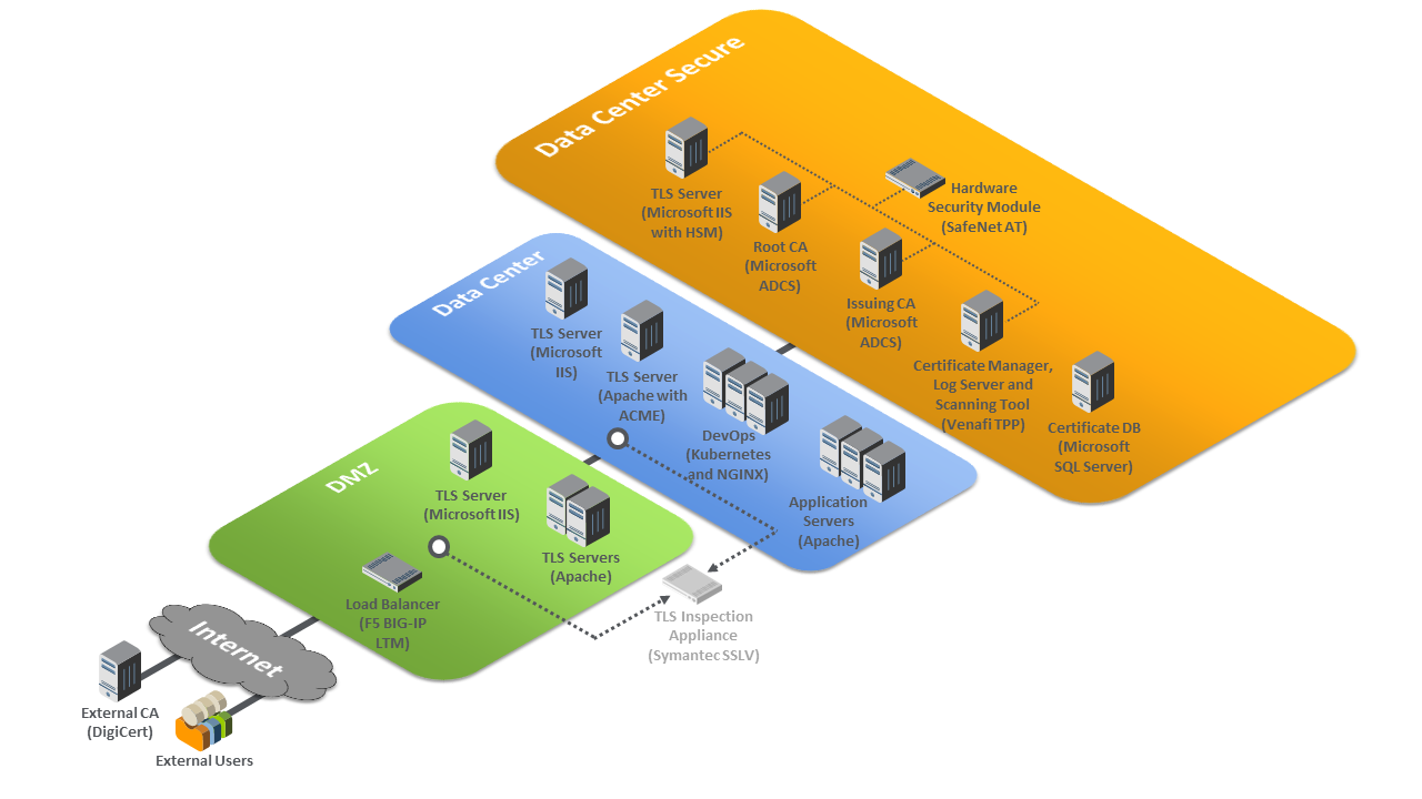
Within the data center secure zone of the logical architecture sit the components that perform TLS server certificate management. These components include internal root and issuing CAs, a certificate manager, a certificate log server, a certificate network scanning tool, a certificate database, and an HSM. For demonstration purposes, a TLS server connected to an HSM is also present in this zone.
The certificate manager can be used in conjunction with the certificate database and the various types of servers in the architecture to demonstrate how to establish and maintain a systematized inventory of certificates (and keys) used on the network. The certificate manager can also continuously monitor TLS certificates (and keys) managed by the inventory system and act upon the status of any certificate (e.g., report a certificate that is expired, about to expire, or does not conform to policy, or it can replace an expired certificate). It can also send expiration reports and notifications to certificate owners and can support disaster recovery by quickly replacing a large number of certificates located throughout the network architecture.
The certificate manager can be used in conjunction with the CAs to enroll and provision certificates (and keys), store attributes with those certificates, and discover the absence of an expected certificate from a machine where it should be installed. The certificate manager can revoke certificates and change the owner associated with that certificate.
The certificate network scanning tool can discover certificates not being managed by the inventory. The certificate log server can record all certificate and private-key management operations, including certificate creation, installation, and revocation; key pair generation; certificate requests and request approvals; certificate and key copying; and certificate and key replacement.
All components in this portion of the architecture—except for the certificate database—are configured to use the HSM, which can securely generate, store, manage, and process the private key corresponding to the TLS server’s certificate. The HSM is capable of storing and protecting the symmetric keys that secure sensitive data in the certificate database, and can generate, store, manage, and process internal CAs’ signing keys.
1.3 Build Architecture Summary
Figure 1-2 depicts the physical architecture of the example implementation deployed in the NCCoE laboratory.
Figure 1‑2 TLS Server Certificate Management Example Implementation: Laboratory Configuration
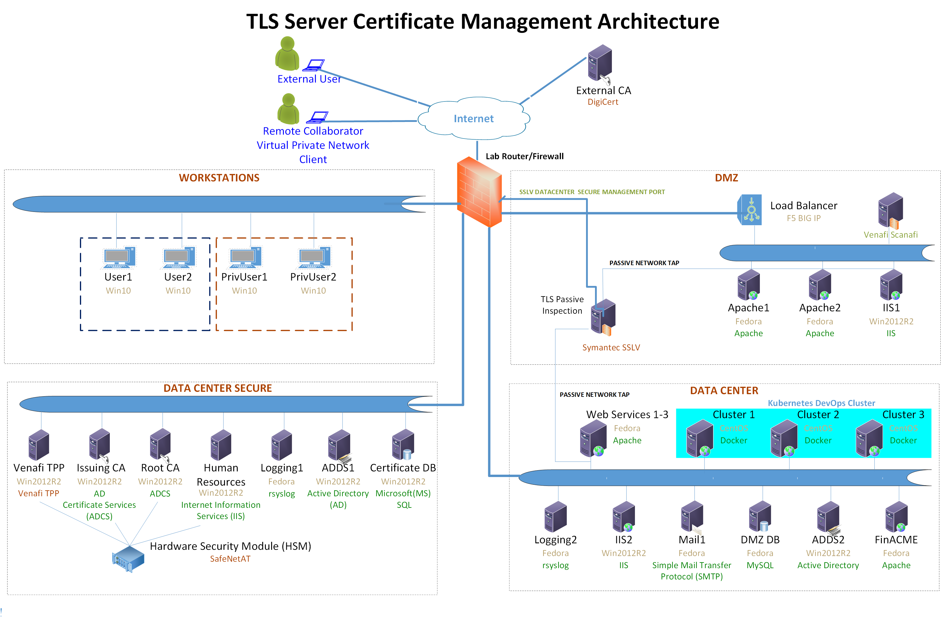
The NCCoE laboratory environment provided the following supporting infrastructure for the example implementation:
firewall-protected connection to the internet where an external CA resides
Windows 2012 server with remote desktop manager, which acts as a jump box to facilitate installation, deployment, and management of server software for collaborative projects
segmented laboratory network backbone that models the separation typically existent between subnetworks belonging to different parts of a medium-to-large-scale enterprise—for example, a DMZ, a data center hosting widely used applications and services, a more secure data center hosting critical security infrastructure components, and a segment containing user workstations
virtual machine and network infrastructure
Windows 2012 server serving as a Microsoft Active Directory (AD) primary domain controller
the Windows 2012 server running AD Certificate Services, including
an internal Root CA that can issue and self-sign its own TLS certificate
an internal issuing CA that:
issues TLS certificates to servers that request them (issue CAs are subordinate to and certified by the root CA)
manages the life cycle of certificates (including request, issuance, enrollment, publication, maintenance, revocation, and expiration)
Microsoft structured query language (SQL) Server hosting the database of TLS certificates and keys, and corresponding configuration data
DevOps automation framework, including Kubernetes, Docker, and Jetstack, that demonstrates automated certificate management when performing open-source container orchestration
Apache, Microsoft IIS, and NGINX servers, which demonstrate various ways of managing TLS server certificates, including remote agentless certificate management, management via the ACME protocol (via the Certbot utility), and management via DevOps
Apache servers used to demonstrate certificate management on second-tier internal application servers
The following collaborator-supplied components were integrated into the above supporting infrastructure to yield the TLS server certificate management example implementation:
Venafi Trust Protection Platform (TPP), which maintains the certificate inventory, performs automated TLS server certificate and private-key management, including monitoring, remediation, and rapid replacement of TLS certificates and keys; TLS certificate and key policy enforcement; automated certificate requests and renewals; automated network scanning for TLS certificates; and logging of certificate and private-key management operations
Symantec SSL Visibility (SSLV), a visibility appliance used to inspect intercepted traffic on encrypted TLS connections
Thales Trusted Cyber Technologies (Thales TCT) Luna SA 1700 HSM, used to securely generate, store, manage, and process the cryptographic key pair; also uses it to sign TLS certificates within a hardened, tamper-resistant physical appliance. It is also used to store other keys, such as the database encryption key and the TLS certificate keys for the key manager component (Venafi TPP) and the CAs
DigiCert external CA, which issues and renews TLS certificates
F5 Networks BIG-IP Local Traffic Manager load balancer, which acts as a TLS proxy and distributes received traffic across a number of other TLS servers
The remainder of this volume describes in detail the installation, configuration, and integration of the above supporting infrastructure and collaborator components.
1.4 Typographic Conventions
The following table presents typographic conventions used in this volume.
Typeface/Symbol |
Meaning |
Example |
|---|---|---|
Italics |
file names and path names; references to documents that are not hyperlinks; new terms; and placeholders |
For detailed definitions of terms, see the NCCoE Glossary. |
Bold |
names of menus, options, command buttons, and fields |
Choose File > Edit. |
|
command-line input, on‑screen computer output, sample code examples, and status codes |
|
Monospace Bold |
command-line user input contrasted with computer output |
service sshd start |
link to other parts of the document, a web URL, or an email address |
All publications from NIST’s NCCoE are available at https://www.nccoe.nist.gov. |
1.5 Supporting Infrastructure
This section is the first in a series of how-to guidance offered in this guide. It contains step-by-step instructions and points to specific, well-known, and trusted information for installing, configuring, and securely maintaining the supporting infrastructure components outlined in previous sections of this document.
All supporting infrastructure components in the following how-to subsections are high-level examples of services and functions that may reside on any network. For example, the Microsoft suite of AD, CA services, domain name server (DNS), web, and database services would typically reside on most organizational networks. Each section follows the other in building the prerequisites. This section on supporting infrastructure is the basis for the subsequent how-to sections on collaborator capabilities.
The lab backbone is the fundamental component of the architecture and forms the basis to develop the implementers’ understanding of the simulated build experience. Guidance is provided for each operating system (OS) installation, with specific instructions on the necessary security and system configurations. Finally, specific ancillary services, installation and security configurations for database services, web services, etc. are provided.
1.5.1 Lab Backbone
The NCCoE has a specific implementation of its supporting lab network infrastructure or lab backbone. Although implementors using this document may possess some or most of the components in the TLS lab backbone, they may encounter slight but significant differences in their lab build. These differences are attributed to how we configured our lab backbone to suit the needs of the TLS lab and the larger multitiered lab community within the NCCoE.
The components and configuration approaches listed below may help clarify what basic capabilities are needed at a minimum to simulate the TLS lab infrastructure backbone.
network topology–designed to provide strict separation of system and workstation duties:
Data Center Secure Network–provides physical and logically secure separation of critical security services from nonprivileged or privileged users without specific security responsibilities
Data Center Network–provides less privileged users with access to security maintenance services that do not require special access to critical security management services
Workstations Network–provides secure, controlled, and monitored access to nonprivileged authorized users to perform organizational business
DMZ–provides secure separation and mitigation of risk to the rest of the critical network services from public access to public-facing services
multiple virtual local area networks (VLANs) and separate subnets–customized naming convention for VLAN names and subnets can be used, or follow the TLS lab approach below:
VLAN 2198 services the Data Center Secure Network 192.168.1.0/24
VLAN 2199 services the Data Center Network 192.168.3.0/24
VLAN 2200 services the Workstations Network 192.168.2.0/24
VLAN 2197 services the DMZ Network 192.168.4.0/24
VLAN 2196 services connections between the F5 load balancer and lab firewall 192.168.5.0/24
VLAN 2202 services wide area network connections between the internet and the firewall; the address used here should mirror whatever is currently used for what the internet provider gave in a subnet address
One or more managed layer three switches must be capable of:
traffic separation for six VLANs with multiple devices on each VLAN (see the architecture diagram for more)
switched port analyzer (SPAN) or port mirroring functions
VLAN trunk ports when using multiple switches
One or more manageable advanced firewalls:
must be capable of accepting at least six Ethernet port connections for all VLANs if using one firewall
must be capable of network address translation (NAT) (port forwarding, hide NAT, and static NAT)
should at least be stateful
should support deep packet inspection for every possible subnet where feasible and financially practical
1.5.2 Supporting Infrastructure Operating Systems
1.5.2.1 Microsoft Windows
Microsoft Windows and Windows Server are within a group of OSs designed by Microsoft to efficiently manage enterprise needs for data storage, applications, networking, and communications. In addition to the standard OSs used, additional ancillary Microsoft services were installed. These are native components of the OS and critical to the TLS lab design. Guidance on configuration of these ancillary services will be discussed later in this document in the Supporting Infrastructure Component Services section.
AD Services
DNS Services
CA Services
1.5.2.1.1 Microsoft Windows and Server Prerequisites
Both Microsoft Windows servers and workstations have minimal hardware prerequisites, listed directly below this paragraph. In addition, TLS lab host configuration information is provided in Table 1-1 and Table 1‑2 below. While it is not imperative that an implementer uses the TLS lab host naming convention and internet protocol (IP) addressing schemes, the tables below may prove useful with informing an organization of the servers and workstations needed should there be customizations to the TLS lab approach.
While the hardware requirements listed below represent the minimum, most business applications of this effort may have higher but differing requirements. All the applications in this TLS build will greatly benefit from adding more than the minimum resources that Microsoft requires, as shown below, in a production environment.
Microsoft’s Minimum Hardware Requirements:
Microsoft Windows Servers 2012
1 gigahertz (GHz) 64-bit processor
512 megabyte (MB) random access memory (RAM)
32 gigabytes (GB) disk space
Microsoft Windows Workstations 2010
1 GHz 64-bit processor
2 GB RAM
20 GB disk space
1.5.2.1.2 Microsoft Windows Server 2012 Installation
For instructions regarding downloading the Microsoft Windows Server 2012, refer to the download and deployment guidance at: https://www.microsoft.com/en-us/evalcenter/evaluate-windows-server-2012-r2.
Given that AD and domain services are critical to the adds1 and adds2 installation process, refer to the Microsoft Active Directory and Domain Services Installation and Configuration section, 1.5.3.1, of this document for full instructions after initial basic installation of the OS.
Please use the table below to name and assign IP addresses to all Microsoft Windows Servers used in the TLS lab build. The Windows Server version used in most cases is Windows 2012 version R2.
Table 1‑1 Naming and Addressing Information for all Microsoft Windows Servers
Host Name |
IP Address |
Subnet |
Gateway |
Software Selection |
|---|---|---|---|---|
iis1.ext-nccoe.org |
192.168.4.4 |
255.255.255.0 |
192.168.4.1 |
Win2012 R2 |
adds1.int-nccoe.org |
192.168.1.6 |
255.255.255.0 |
192.168.1.1 |
Win2012 R2 |
HSMrootca.int-nccoe.org |
192.168.1.10 |
255.255.255.0 |
192.168.1.1 |
Win2012 R2 |
BaseSubCA.int-nccoe.org |
192.168.1.41 |
255.255.255.0 |
192.168.1.1 |
Win2012 R2 |
HRhsm |
192.168.1.16 |
255.255.255.0 |
192.168.1.1 |
Win2012 R2 |
Venafi1 |
192.168.1.81 |
255.255.255.0 |
192.168.1.1 |
Win2012 R2 |
VTPPTrustDB |
192.168.1.89 |
255.255.255.0 |
192.168.1.1 |
Win2012 R2 |
iis2.int-nccoe.org |
192.168.3.5 |
255.255.255.0 |
192.168.3.1 |
Win2012 R2 |
adds2.int-nccoe.org |
192.168.3.7 |
255.255.255.0 |
192.168.3.1 |
Win2012 R2 |
dmzdc.ext-nccoe.org |
192.168.3.8 |
255.255.255.0 |
192.168.3.1 |
Win2012 R2 |
1.5.2.1.3 Microsoft Windows 10 Workstations Installation
For instructions regarding download of the Microsoft Windows 10 workstation used in this TLS lab build, refer to the guidance at https://www.microsoft.com/en-us/software-download/windows10.
Please use the table below to name and assign IP addresses to all Microsoft Windows 10 workstations used in the TLS lab build. The Windows 10 version used in most cases is Windows 10 Pro.
Table 1‑2 Naming and Addressing Information for all Microsoft Windows 10 Workstations
Host Name |
IP Address |
Subnet |
Gateway |
Software Selection |
|---|---|---|---|---|
win10-1.int-nccoe.org |
192.168.2.11 |
255.255.255.0 |
192.168.2.1 |
Win10_Pro |
win10-2.int-nccoe.org |
192.168.2.2 |
255.255.255.0 |
192.168.2.1 |
Win10_Pro |
privuser1.int-nccoe.org |
192.168.2.3 |
255.255.255.0 |
192.168.2.1 |
Win10_Pro |
privuser2.int-nccoe.org |
192.168.2.4 |
255.255.255.0 |
192.168.2.1 |
Win10_Pro |
1.5.2.2 Linux
Linux is a family of free and open-source OSs based on the Linux kernel, an OS kernel first released on September 17, 1991, by Linus Torvalds. Fedora Server is a Red Hat Corporation-supported, short life- cycle, and fully community-supported server OS. Fedora enables system administrators of any skill to freely (in most cases) make use of the very latest technologies available in the open-source community.
The CentOS Linux distribution is no different in its ability to allow mostly free use of world-class security and general IT capabilities. CentOS is a manageable and reproducible platform derived from the sources of Red Hat Enterprise Linux (RHEL) by an open-source community of volunteers.
1.5.2.2.1 Linux Prerequisites
Table 1‑3 and Table 1‑4 include the host names and IPs used in the TLS lab for all Linux machines. The recommended minimum hardware requirements for the default installations of Fedora and CentOS have been noted below. An organization’s requirements may differ. However, it is highly recommended that the maximum optimal configuration (in accordance with the organization’s available resources) for each system be applied, as all the applications used in this TLS lab build will benefit from more than the minimum resources in a production environment.
1 GHz or faster processor
1 GB system memory
10 GB unallocated drive space
1 VMXNET 3 network adapter
1.5.2.2.2 Fedora and CentOS Installation
The OS installation process for the TLS lab Linux machines did not deviate from the standard installation instructions that exist for each Linux distributor. The links below provide standard guidance for the Fedora and CentOS installations.
When running through the installation process, in some cases, a standard Fedora installation for software selection will not suffice. Should this occur, use Table 1-3. If the Software Selection column includes Fedora Server/Basic Web Server, select Fedora Server for Base Environment, then select Basic Web Server installation for add-ons, and when prompted, select software packages during the installation.
The CentOS Software Selection column includes Basic Web Server—select this as the software package to install when prompted during the installation process for CentOS.
Please use Table 1-3 for IP, host name, and other installation-specific options for all Fedora-based systems in the TLS lab build.
Table 1‑3 Naming and Addressing Information for All Fedora-Based Systems
Host Name |
IP Address |
Subnet |
Gateway |
Software Selection |
|---|---|---|---|---|
syslog2.int-nccoe.org |
192.168.3.12 |
255.255.255.0 |
192.168.3.1 |
Fedora Server |
finacme.int-nccoe.org |
192.168.3.61 |
255.255.255.0 |
192.168.3.1 |
Fedora Server/ Basic Web Server |
mail1.int-nccoe.org |
192.168.3.25 |
255.255.255.0 |
192.168.3.1 |
Fedora Server |
dmzdb.ext-nccoe.org |
192.168.3.6 |
255.255.255.0 |
192.168.3.1 |
Fedora Server |
syslog1.int-nccoe.org |
192.168.1.12 |
255.255.255.0 |
192.168.1.1 |
Fedora Server |
apache1.ext-ncccoe.org |
192.168.4.2 |
255.255.255.0 |
192.168.4.1 |
Fedora Server/ Basic Web Server |
apache2.ext-nccoe.org |
192.168.4.3 |
255.255.255.0 |
192.168.4.1 |
Fedora Server/ Basic Web Server |
ws1.int-nccoe.org |
192.168.3.87 |
255.255.255.0 |
192.168.3.1 |
Fedora Server/ Basic Web Server |
ws2.int-nccoe.org |
192.168.3.88 |
255.255.255.0 |
192.168.3.1 |
Fedora Server/ Basic Web Server |
ws3.int-nccoe.org |
192.168.3.89 |
255.255.255.0 |
192.168.3.1 |
Fedora Server/ Basic Web Server |
Please use Table 1-4 for IP, host name, and other installation-specific options for all CentOS servers used in the TLS lab build.
Table 1‑4 Naming and Addressing Information for All CentOS Servers
Host Name |
IP Address |
Netmask |
Gateway |
Software Selection |
|---|---|---|---|---|
scanafi.ext-nccoe.org |
192.168.4.107 |
255.255.255.0 |
192.168.4.1 |
Infrastructure Server |
cluster1.int-nccoe.org |
192.168.3.103 |
255.255.255.0 |
192.168.3.1 |
Basic Web Server |
cluster2.int-nccoe.org |
192.168.3.104 |
255.255.255.0 |
192.168.3.1 |
Basic Web Server |
cluster3.int-nccoe.org |
192.168.3.105 |
255.255.255.0 |
192.168.3.1 |
Basic Web Server |
1.5.3 Supporting Infrastructure Component Services
1.5.3.1 Microsoft Active Directory and Domain Services Installation and Configuration
Active Directory Services (ADS) and DNS work together to store directory data and make those resources available to administrators and users. For example, ADS stores information about user accounts such as names and passwords. Security is integrated with ADS through log-on authentication and enforced access control for user, file, directory, and other system objects in the directory of services. Administrators are able to manage directory data and organization roles across the enterprise. They can assign permissions to users, which allows users to access resources anywhere on the network. ADS authenticates and authorizes all users and computers in a Windows domain network. ADS works in conjunction with Group Policies Objects (GPOs) in assigning and enforcing security policies for all computers.
A DNS is a protocol for how computers translate domain names. It manages a database used to resolve domain names to IP addresses, allowing computers to identify each other on the network. DNS is the primary locator service for AD. ADS is highly dependent on the DNS in most cases, and as a result, most implementations—including the TLS lab—opt to install the DNS service on the same server as the ADS.
1.5.3.1.1 ADS and DNS Prerequisites
Below are the minimum recommended tools, services, and configurations needed to install ADS and DNS.
The adds1 and adds2 hosts should be built with the Windows Server 20012 OS installed. As described in Section 1.5.2.1.2 of this document, there are two ADS and DNS servers. The TLS lab ADS and DNS server names used are adds1.int-nccoe.org and adds2.int-nccoe.org. (Note: The DNS server may be run locally on the same Active Directory Domain Services [ADDS] server.)
local network configurations–all of the local network VLANs, IP addresses, and proper routes
familiarity with Server Manager
Server Manager is a Windows Server management console that allows administrators to install, configure, and manage server roles and features. Administrators can manage local and remote servers without having physical access to them. The ADS and DNS installation process is integrated with Server Manager, which can be used when installing other server roles.
1.5.3.2 ADS and DNS Installation
For instructions on deploying ADS and DNS on a Windows 2012 server, refer to the guidance at one of the links below:
Graphical User Interface (GUI)-Based Installation: https://docs.microsoft.com/en-us/windows-server/identity/ad-ds/deploy/ad-ds-installation-and-removal-wizard-page-descriptions
Command Line-Based Installation: https://docs.microsoft.com/en-us/windows-server/identity/ad-ds/deploy/install-active-directory-domain-services–level-100-
1.5.3.3 Certificate Authority Services
In an organization where public key infrastructure (PKI) has been implemented, a CA is responsible for validating the identity of users and computers. The CA assigns a trusted credential for use in authenticating user and system identities, by issuing a digitally signed and trusted certificate. The CA can also assist in managing revocation and renewal of its signed certificates.
The first CA built and implemented in a PKI environment is often referred to as the root CA. As the originator and root of trust, the root CA authorizes all subsequent CAs, called subordinates or issuing CAs. Subordinate CAs can also designate their own subsidiaries as defined by the root CA, which results in a certificate hierarchy. The metadata supplied in all certificates issued to CAs lower in the hierarchy from the root CA contain a trace path back to the root.
A compromised root CA will cripple any organization that depends on the integrity of its issued PKI certificates, even in lightweight transactions. With full control or significant unauthorized access to the root CA, a malicious actor may fully infiltrate any transaction that relies on the integrity of the trust chain where that root CA presides as the anchor. It is recommended all organizations—size notwithstanding—implement an enterprise stand-alone offline root CA and separate issuing subordinate CA(s) topology wherever possible. Doing so mitigates many of the risks associated with compromised root CAs.
The TLS lab followed Microsoft’s guidance to develop a highly secure offline stand-alone root CA coupled with an enterprise online issuing CA. The following CA installation and configuration how-to guidance aligns with that goal.
1.5.3.3.1 CA Prerequisites
The prerequisite steps to configure the CA(s) include:
Build HSMrootca.int-nccoe.org and BaseSubCA.int-nccoe.org in accordance with the OS installation and configuration instructions in Section 1.5.2.1.2.
Join BaseSubCA.int-nccoe.org to the already created int-nccoe.org domain.
HSMrootca.int-nccoe.org and BaseSubCA.int-nccoe.org should have network connections to all the TLS lab subnets needed for CA certificate issuance.
1.5.3.3.2 Installation of Offline Root and Issuing CA
In this implementation scenario, the offline root CA is built, configured, and established as the root of the trust chain. The root CA is then configured to securely sign and issue certificates for all of its subordinates. Afterward, it is taken completely offline. Being taken offline includes complete power- down and highly secures physical storage of the root CA device (specifically the hard drive if possible).
Installation of the root CA through the Server Manager console can be done by installing Active Directory Certificate Services (ADCS). ADCS is used to create CAs and configure their role to issue and manage certificates. For instructions on installing ADCS on the root CA and issuing CA server, refer to the steps below:
In the Server Manager, select Manage > click on Add Roles and Features.
Follow the Add Roles and Features wizard > in Select Installation Types, select Role-Based or feature installation.
In Select destination server, confirm Select a server from the server pool is selected > select your local computer.
In Select server roles > under Roles, select Active Directory Certificate Services > click Add Features.
In Select features > click Next.
In Active Directory Certificate Services > click Next.
In Select role services > in Roles, select Certification Authority.
In Confirm installation records > click Install.
When installation is complete, click Close.
1.5.3.3.3 Offline Root CA Configuration
After installing ADCS, refer to the steps below to configure and specify cryptographic options for the root CA:
Run Post-deployment Configuration wizard > click on Configure Active Directory Services link.
In Credentials, read the credentials information. If needed, provide administrator credentials.
In Role Services > select Certification Authority.
In Setup Type > select Standalone CA.
In CA Type > select Root CA.
In Private Key > select Create a new private key to specify type of private key.
In Cryptography for CA:
Select a cryptographic provider: RSA#SafeNet Key Storage Provider.
Key Length = 2048
Select the hash algorithm for signing certificates issued by this CA: SHA256.
In CA Name > specify the name of CA > RootCA.
For Validity Period > select 2 Years.
Specify the database location > C:\Window\system32\CertLog.
Review the CA configuration and click Configure.
Click Close when the confirmation message appears.
To configure the CRL Distribution Point (CDP) and Authority Information Access (AIA) extensions on the root CA, follow the steps below:
In Server Manager, go to Tools > select Certification Authority.
Right-click RootCA > click Properties.
Click the Extensions tab. Ensure Select Extension is set to CDP.
In the Specify locations from which users can obtain a certificate revocation list (CRL), do the following:
Select the entry
file://<ServerDNSName>/CertEnroll/<CaName><CRLNameSuffix><DeltaCRLAllowed>.crl and then click Remove. In Confirm removal, click Yes.
Select the entry
http://<ServerDNSName>/CertEnroll/<CaName><CRLNameSuffix><DeltaCRLAllowed>.crl and then click Remove. In Confirm removal, click Yes.
In Specify locations from which users can obtain a certificate revocation list (CRL), click Add.
In Add Location, in Location, type http://BaseSubCA/CertEnroll/<CaName><CRLNameSuffix><DeltaCRLAllowed>.crl and then click OK. This returns to the CA properties dialogue box.
On the Extensions tab, select the following checkboxes:
Include in CRLs. Clients use this to find the Delta CRL locations.
Include in the CDP extension of issued certificates.
In Specify locations from which users can obtain a certificate revocation list (CRL), select the entry that starts with ldap://CN=CATruncatedName>,CRLNameSuffix>,CN=<ServerShortName>.
On the Extensions tab, select the following checkbox:
Include in all CRLs. Specifies where to publish in the Active Directory when publishing manually.
In Specify locations, users can obtain a certificate revocation list (CRL). Select the entry C:\Windowssystem32CertSrvCertEnroll<CaName><CRLNameSuffix><DeltaCRLAllowed>.crl.
On the Extensions tab, select the following checkboxes:
Publish CRLs to this location.
Publish Delta CRLs to this location.
Change Select extension to Authority Information Access (AIA).
In the Specify locations, users can obtain a certificate revocation list (CRL) do the following:
Select the entry http://<ServerDNSName>/CertEnroll/<ServerDNSName>_<CaName><CertificateName>.crt and then click Remove. In Confirm removal, click Yes.
Select the entry file://<ServerDNSName>/CertEnroll/<ServerDNSName>_<CaName><CertificateName>.crt and then click Remove. In Confirm removal, click Yes.
In Specify locations, users can obtain a CRL, click Add.
In Add Location, in Location, type http://BaseSubCA/CertEnroll/<ServerDNSName>_<CaName><CertificateName>.crt and then click OK. This returns to the CA properties dialogue box.
On the Extensions tab, select the following checkbox:
Include in the AIA of issued certificates.
In Specify locations from which users can obtain a certificate revocation list (CRL), select the entry that starts with ldap://CN=CATruncatedName>,CN=AIA,CN=PublicKeyServices.
On the Extensions tab, select the following checkbox:
Include in the AIA extension of issued certificates.
In Specify locations, users can obtain a certificate revocation list CRL. Select the entry C:\Windows\system32\CertSrv\CertEnroll\<ServerDNSName>_<CaName><CertificateName>.crt.
On the Extensions tab, ensure AIA extension of issued certificates is not selected.
When prompted to restart Active Directory Certificate Services, click No. Restart that service later.
Go back to RootCA and expand folders to right-click on Revoked Certificates > select All Tasks > click Publish.
When prompted to Publish CRL, select New CRL > click OK.
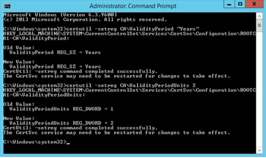
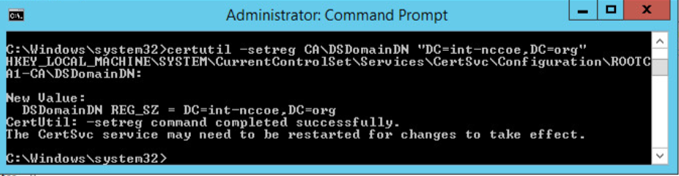
To configure the Registry Settings, run cmd as an administrator and type the following commands:
certutil -setreg CA\ValidityPeriod “Years”

certutil –setreg CA\ValidityPeriodUnits 2
certutil -setreg CA\DSConfigDN “CN=Configuration,DC=int-nccoe,DC=org”
cerutil -setreg CA\DSDomainDN “DC=int-nccoe,DC=org”

For it to accept the new values, restart services > go to Administrative Tools > double-click Certification Authority.
Select the RootCA > right-click to select All Tasks > click Start Service.
Go back to RootCA to expand folders > right-click on Revoked Certificates > select All Tasks > click Publish to publish revoked certificates.
1.5.3.3.4 Enterprise Subordinate/Issuing CA Configuration
After installing ADCS, follow the steps below to configure and specify cryptographic options for the issuing CA:
Run Post-deployment Configuration wizard > click on Configure Active Directory Services link.
In Credentials, read the credentials information. If needed, provide administrator credentials.
In Role Services > select Certification Authority.
In Setup Type > select Enterprise CA.
In CA Type > select Subordinate CA.
In Private Key > select Create a new private key to specify type of private key.
In Cryptography for CA:
Select a cryptographic provider: RSA#SafeNet Key Storage Provider.
Key Length = 2048
Select the hash algorithm for signing certificates issued by this CA: SHA256.
In CA Name > specify the name of the CA > BaseSubCA.
In Certificate Request > select Save a certificate request to file on the target machine > specify folder location > C:BaseSubCA.int-nccoe.org_int-nccoe-BASESUBCA-CA.req.
In CA Database > specify the folder location for the certification database > C:\Windows\system32\CertLog.
In Confirmation > confirm configurations and select Configure > click Close.
Copy the BaseSubCA request file from the BaseSubCA server to the RootCA server at C:\Windows\System32\CertServ\CertEnroll.
Copy rootCA.crl and rootCA.crt to the BaseSubCA server at C:\Windows\System32\CertServ\CertEnroll.
To issue a certificate to the BaseSubCA server from the RootCA server, go to Administrative Tools > double-click Certification Authority.
Select BaseSubCA > right-click to select All Tasks > click Submit new request.
Select and open the request file in the dialogue box.
Go back to the Certification Authority > select BaseSubCA and expand folders > click on Pending Requests.
Right-click the pending certificate > right-click to select All Tasks > click Issue.
Go to Issued Certificates to view the issued certificate.
Double-click on the issued certificate.
Go to the Details tab > click Copy to File.
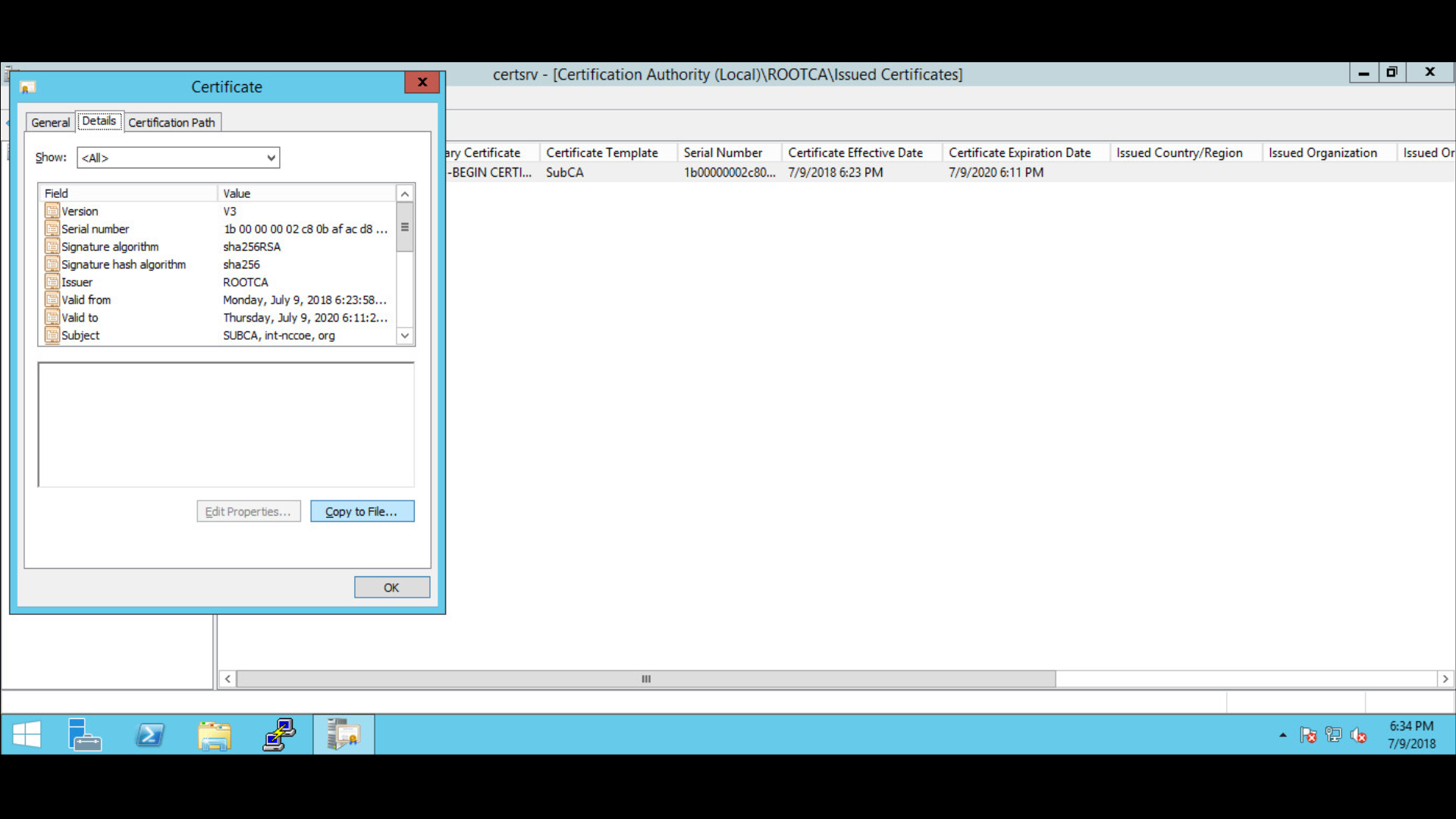
Follow the Certificate Export wizard and select the desired format:
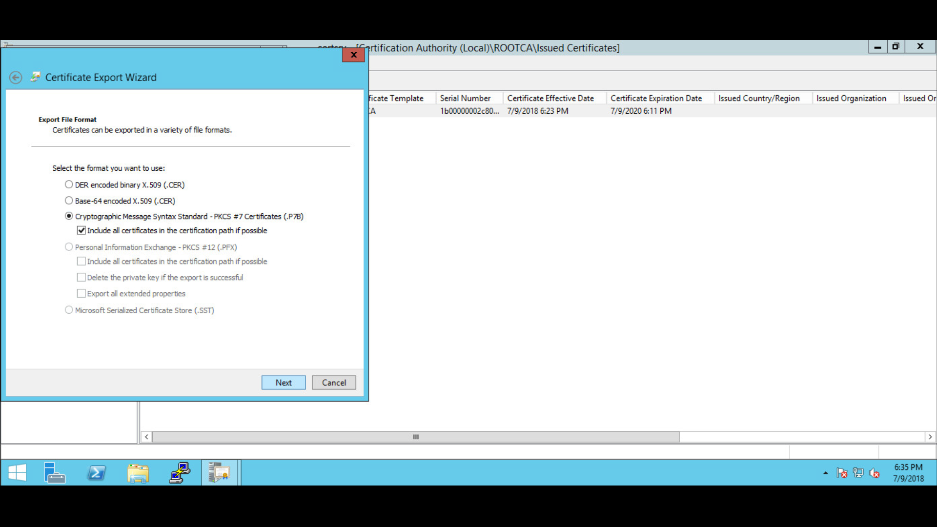
Save the file as subCA > file type is PKCS #7 Certificates (*.p7b).
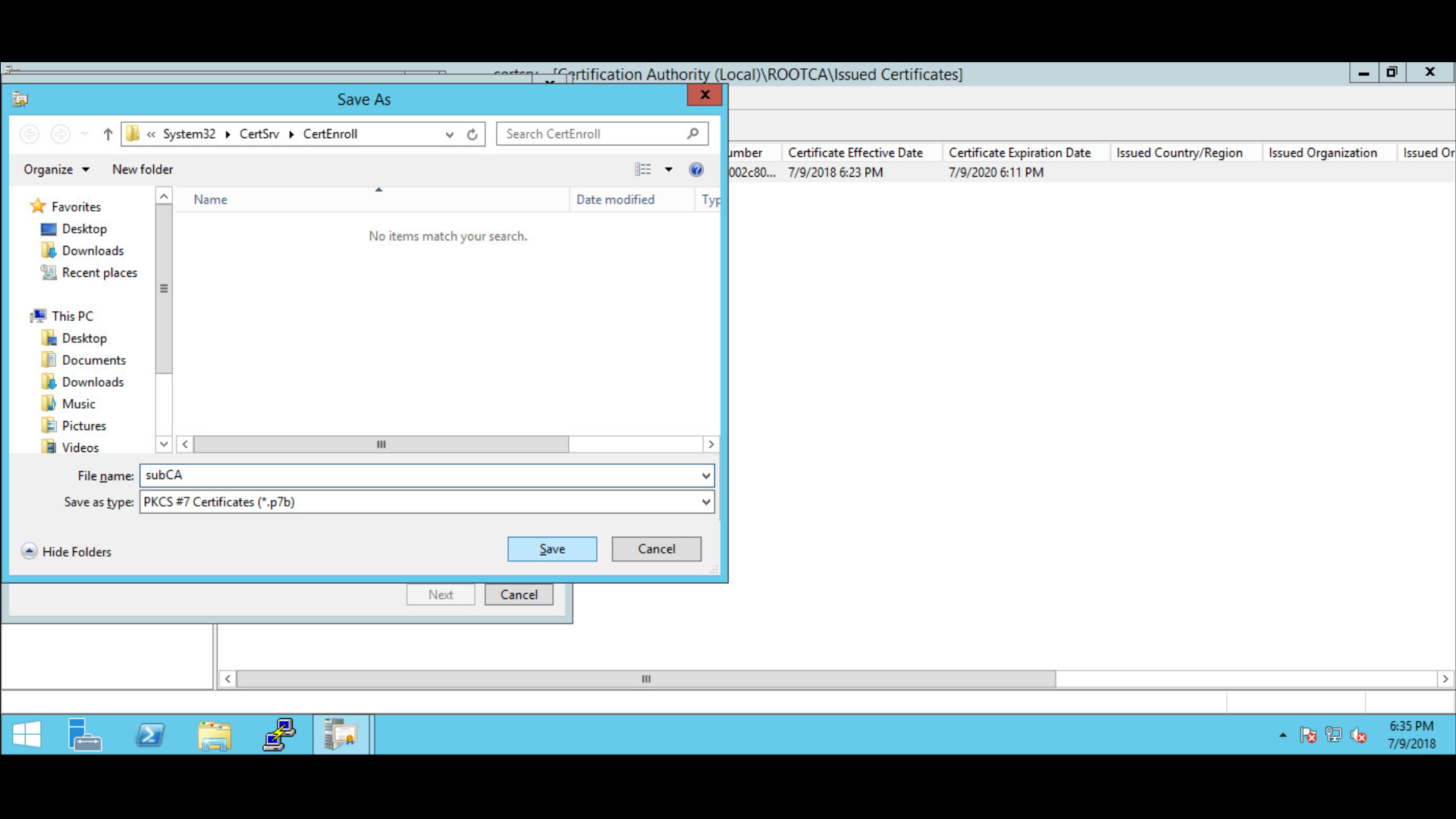
Specify the file name to export:
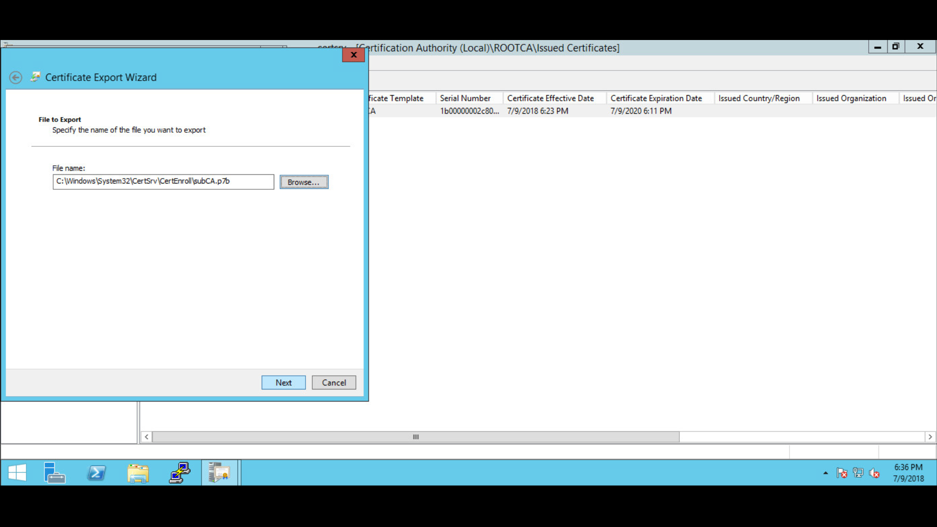
Complete the Certificate Export Wizard by confirming settings > click Finish.
In Export was successful > click OK.
Copy subCA.p7b from the RootCA server at C:\WindowSystem32\CerServ\CertEnroll to the BaseSubCA server at C:\WindowSystem32\CerServ\CertEnroll.
On the BaseSubCA server > shift right-click > open the command prompt.
Publish the CA Root certificate into Directory Services with the following command:
certutil -dspublish -f (tab to rootCA.crt file) RootCA
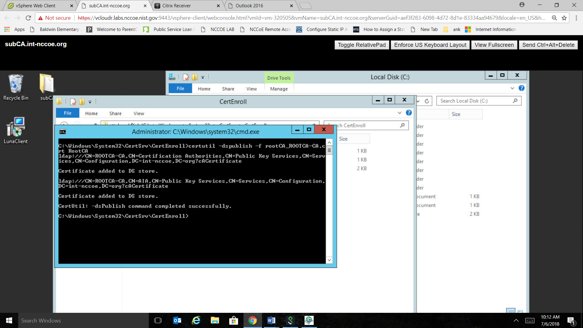
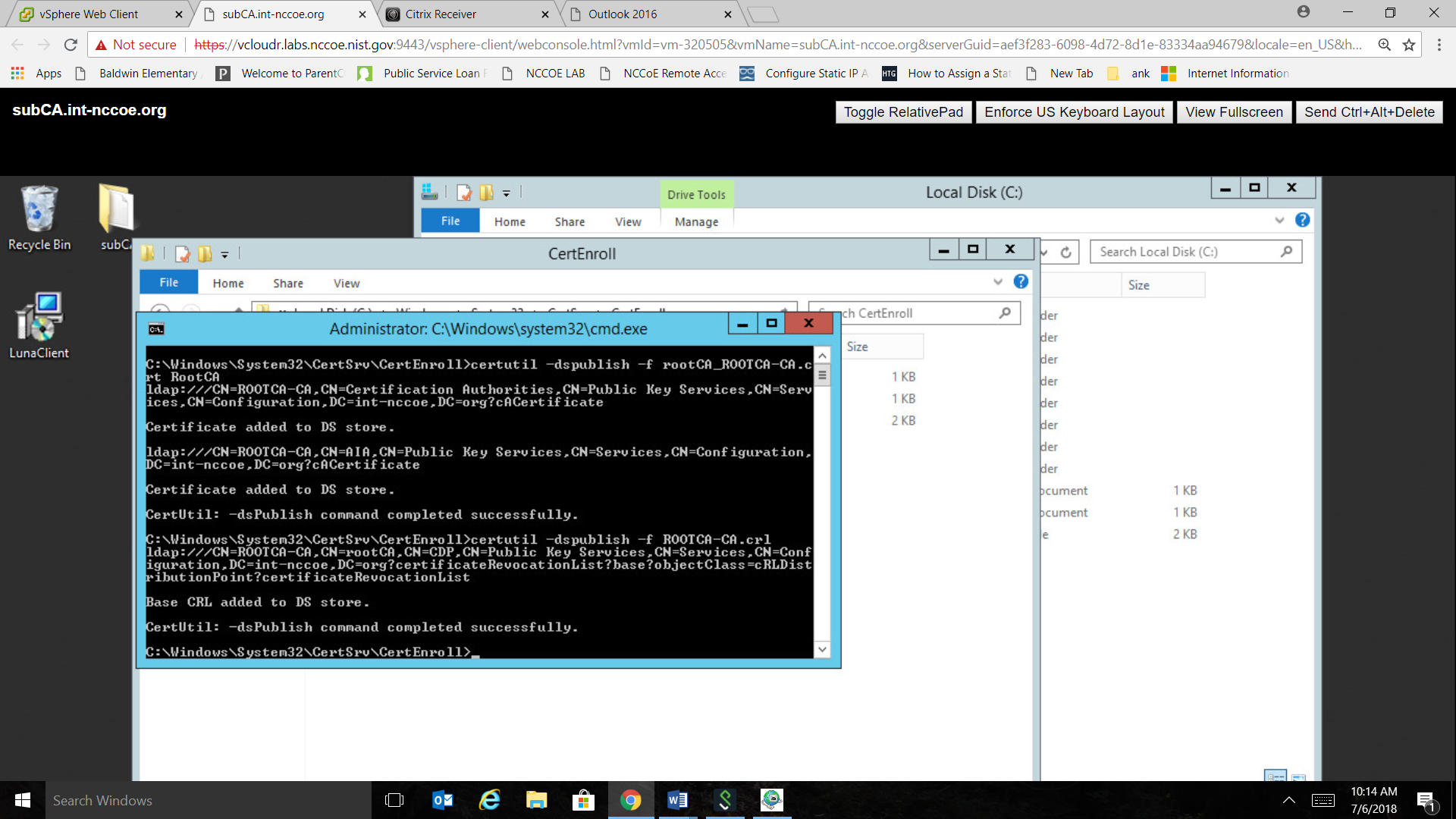
To publish the crl file, type the following command:
certutil -dspublish -f (tab to .crl file)
Set the Domain Policy to make the RootCA trusted by all domain computers.
Install the certificate in the subCA server > go to Administrative Tools > double-click Certification Authority.
Select the CA > right-click to select All Tasks > click Install CA Certificate.
Select the .p7b file to complete the CA installation.
A warning message will be received that the revocation server is offline > click OK to ignore the message.
Power down the RootCA server.
Go to Administrative Tools > right-click the CA > select All Tasks > click Start Service to start services.
Install .crt files on the Default Domain Policy.
Go to the domain controller (DC).
Go to Administrative Tools > open Group Policy Management console.
Go to the organization’s domain > right-click the Default Domain Policy folder > select Edit.
Navigate to Computer Configuration, go to Policies > Window Settings > Security Settings > Public Key Policies > right-click Intermediate Certification Authorities > select Import.
Follow the Certificate Import Wizard > click Next.
Select the subCA.crt file to import > click Next to import file.
Confirm details > click Finish.
A dialogue box will pop up to confirm The import was successful.
Go to Trusted Root Certification Authority folder and right-click> select Import.
Follow the Certificate Import Wizard > click Next.
Select the rootCA.crt file to import > click Next to import file.
Confirm details > click Finish.
A dialogue box will appear to confirm The import was successful.
1.5.4 Database Services
1.5.4.1 Microsoft SQL Database Services
Microsoft SQL (MSQL) Server is a relational database management system developed by Microsoft. As a database server and a software product, its primary function is to store and retrieve data as requested by other software applications. MSQL can operate on the same or another computer across a network.
1.5.4.1.1 Prerequisites for MSQL Database Services
The information below is Microsoft’s recommended minimum for default installation of MSQL. An organization’s requirements may differ. However, all applications can benefit from more than the minimum resources in a production environment.
1.4 GHz 64-bit processor
1 GB RAM
6 GB disk space
administration privileges (local installations must run Setup as an administrator)
One MSQL database was used for the TLS lab build to support the Venafi TPP server. This guide installs only the basic MSQL application on a server. This prepares the specific configurations that are discussed in the Venafi TPP How -To guidance section. As a prerequisite, see the OS installation instructions in Section 1.5.2.1.2 to build the VTPPTrustDB.int-nccoe.org server.
1.5.4.1.2 Installation of MSQL Database Services
To install MSQL on a Windows 2016 Server, follow the Microsoft steps in the link below:
Download here: https://www.microsoft.com/en-us/sql-server/sql-server-downloads?&OCID=AID739534_SEM_at7DarBF&MarinID=sat7DarBF_340829462634_microsoft%20sql%20download_e_c__68045082145_kwd-343189224165_
Install and configure here: https://docs.microsoft.com/en-us/sql/database-engine/install-windows/install-sql-server-from-the-installation-wizard-setup?view=sql-server-2017
Install MSQL as a stand-alone server.
Specify the Database Engineer Configuration in step 15 by selecting SQL Server Administrators.
1.5.4.2 MariaDB Database Services
The original inventors of MySQL developed the MariaDB server, which is highly compatible with MySQL. This allows a drop-in replacement capability with library binary parity and exact matching with MySQL’s application programming interfaces and commands.
Like MySQL, the open-source version of MariaDB can scale and performs as well as most enterprise database servers. The TLS lab uses the MariaDB to serve its public-facing (DMZ) web-based TLS services described in this document.
1.5.4.2.1 Prerequisites for MariaDB Database Services
The host named dmzdb.ext-nccoe.org should have already been set up within the Fedora OS how-to guidance of Section 1.5.2.2.2. Complete this setup prior to installing the MariaDB server.
1.5.4.2.2 Installation of MariaDB Database Services
To download and install MariaDB, please refer to the fedoraproject.org guidance at https://fedoraproject.org/wiki/MariaDB
1.5.4.2.3 Configuration of MariaDB Database Services
MariaDB is used to serve dynamic web content with the Drupal application. All three web servers used in the DMZ must be configured via Drupal to point to one database. As a result, the database must be configured to accept connections from the Drupal web servers. MariaDB can be configured by using the Fedora Linux command line. To start, first set up a secure password for the root and any other administrative accounts (see the MariaDB setup instructions on how to specify other accounts). Log in to the dmzdb.int-nccoe.org by using the local command line shell or secure remote administration client (ssh, putty, openssh). Once logged into the system, use the following command to launch MariaDB from the Fedora Linux:
[root@dmzdb ~]# mysql -pNote: Although the root account is displayed here as the login account, configuring MariaDB with the root user in a production environment is not recommended.
Configure the database to allow remote connections from either the IP addresses or host names used in the TLS lab. If the IP addresses and host names were customized (apache1: 192.168.4.2, apache2: 192.168.4.3, iis1: 192.168.4.4), please double-check and change the IP addresses in the database by using the commands below. If custom host names were used in place of the IP addresses, the database DNS or host resolution is set to properly resolve to the right IP addresses.
[root@dmzdb ~]# mysql -p

Enter password:

Welcome to the MariaDB monitor. Commands end with ; or \\g.

Your MariaDB connection id is 1012018

Server version: 10.2.16-MariaDB MariaDB Server

Copyright (c) 2000, 2018, Oracle, MariaDB Corporation Ab and others.

Type 'help;' or '\h' for help. Type '\c' to clear the current input statement.

MariaDB [(none)]> create database EXT_NCCOE_DB;

MariaDB [(none)]> grant all privileges on EXT_NCCOE_DB.\* to 'EXTADMIN'@'192.168.4.2' IDENTIFIED BY 'YOUR PASSWORD';

MariaDB [(none)]> grant all privileges on EXT_NCCOE_DB.\* to 'EXTADMIN'@'192.168.4.3' IDENTIFIED BY 'YOUR PASSWORD';

MariaDB [(none)]> grant all privileges on EXT_NCCOE_DB.\* to 'EXTADMIN'@'192.168.4.4' IDENTIFIED BY 'YOUR PASSWORD';

MariaDB [(none)]> quit;
Add rules to the local Linux firewall to allow database traffic inbound. Please use the following commands to allow database traffic to inbound ports on the MariaDB server:
Type the following command to allow database connections to Apache:
iptables-I INPUT -p tcp –dport 3306 -mstate --state related, ESTABLISHED, new -j ACCEPT
1.5.5 TLS Web Services
1.5.5.1 Microsoft Internet Information Services
The web server (IIS) role in Windows Server 2012 provides a means for hosting websites, services, and applications. IIS information can be shared with users on the internet, an intranet, or an extranet. IIS is a unified web platform that integrates IIS, ASP.NET, File Transfer Protocol services, Personal Home Page Hypertext Preprocessor (PHP), and Windows Communication Foundation.
The TLS lab utilized the IIS server as a public-facing member of a load balance web cluster for public-facing internet services. It was also used as an intranet server to simulate an employee web-based knowledge management system that is internal to an organization.
1.5.5.1.1 IIS Prerequisites
Complete the following prerequisite steps prior to installing and configuring IIS:
Server iis2.int-nccoe.org should ideally be a member of the domain for more streamlined TLS certificate management.
The IIS administrator must have Request Certificates permission on the issuing CA.
The iis1.int-nccoe.org and iss2.int-nccoe.org servers should be set up per Section 1.5.2.1.2.
Server iis1.int-nccoe.org should be used for the public-facing web-based cluster.
Server iis2.int-nccoe.org should be used as the internal intranet server.
1.5.5.2 IIS Installation
IIS is the topic of this section, however, the PHP is a key component of the IIS installation for the TLS lab implementation of the iis1.int-nccoe.org internet-facing server. PHP is a script language and interpreter and a server-side language that assists IIS and Drupal in serving dynamic web content.
Please follow the instructions in the link below to install IIS and PHP. The iis2.int-nccoe.org server can be set up without PHP installed. Please follow the same instructions below for the iis2 server—skip the PHP part of the installation process.
Windows 2012 Server provides several methods for enrolling certificates: two of these are the Certificate Enrollment Policy (CEP) and Certificate Enrollment Service (CES). The CEP web service enables users and computers to obtain certificate enrollment policy information. This information includes what types of certificates can be requested and what CAs can issue them. CES provides another web service that allows users and computers to perform certificate enrollment by using the hypertext transfer protocol secure (https). To separate traffic, the CES can be installed on a computer that is separate from the CA. Together with the CEP web service, CES enables policy-based certificate enrollment when the client computer is not a member of a domain or when a domain member is not connected to the domain. CEP/CES also enables cross-forest, policy-based certificate enrollment.
For the purpose of the lab, the IIS configuration option selected for authentication type for the CES is Windows integrated authentication. This option provides Kerberos authentication for devices connected to the internal network and joined to a domain. The service account selected is the Use the built-in application pool identity.
To configure the SSL protocol to encrypt network traffic, obtain a certificate for IIS, and configure https on the default website, please refer to the link below.
1.5.5.3 Apache Web Services
The Apache HTTP Server is a free and open-source cross-platform web server software, released under the terms of Apache License 2.0. Apache is developed and maintained by an open community of developers under the Apache Software Foundation.
1.5.5.3.1 Apache Web Services Prerequisites
The Apache web server was used extensively throughout the TLS lab architecture to demonstrate the various means of automated and manual management of TLS certificates. The following servers should be built in accordance with the instructions in Section 1.5.2.2.2.
apache1.ext-ncccoe.org
apache2.ext-nccoe.org
ws1.int-nccoe.org
ws2.int-nccoe.org
ws3.int-nccoe.org
1.5.5.3.2 Apache Installation
PHP is a key component of the Apache installation for the TLS lab implementation of all of the above web servers. PHP assists Apache and Drupal in serving dynamic web content. Please follow the instructions below for installing Apache and PHP.
For the Apache web server installation, please refer to this guidance: https://docs.fedoraproject.org/en-US/fedora/f28/system-administrators-guide/servers/Web_Servers/
All Drupal installations have dependencies on the base PHP application and its supplemental modules. In addition to the base PHP installation, also install the additional modules by using the following command.
dnf install drush php php-mysqli php-json php-mbstring php-gd php-dom php-xml php-simplexml php-cli php-fpm php-mysqlnd php-pdop-gd php-dom php-xml
php-simplexml php
1.5.5.3.3 Apache Web Services Configuration
The TLS lab enabled https on the Apache web servers. For instructions on setting up OpenSSL, refer to the “Using mod_ssl” section from the following link: https://docs.fedoraproject.org/en-US/quick-docs/getting-started-with-apache-http-server/
To allow http and https connections through the local Fedora firewall to Apache, perform the following steps:
Type the following command to allow http connections to Apache:
iptables-I INPUT -p tcp –dport 80 -mstate --state related, ESTABLISHED, new -j ACCEPTType the following command to allow https connections to apache:
iptables-I INPUT -p tcp –dport 443 -mstate --state related, ESTABLISHED, new -j ACCEPT
Save the newly created firewall rules with the following command: iptables-save
1.5.5.4 Drupal Web Content Management Services
Drupal is a scalable, open platform for web content management. Drupal can be installed on multiple OSs, including, Fedora, CentOS, and IIS. The TLS lab utilized Drupal to serve web pages on all three of the load balanced web servers in the public-facing DMZ.
1.5.5.4.1 Drupal Prerequisites
PHP 5.5.9 or higher
MySQL 5.5.3 or MariaDB 5.5.20
Apache or IIS web server
1.5.5.4.2 Drupal Web Content Management System Download and Installation
One server should run throughout the setup process, including the database setup. The remaining two servers should be set up to point to the existing database once the first server has been set up. All web servers should be set up to use MariaDB, not MSQL. Use the guidance below for download, installation, and configuration of Drupal to simulate the TLS lab architecture:
download: https://www.drupal.org/download
Apache installation and configuration: https://www.drupal.org/docs/7/install
IIS installation and configuration: https://www.drupal.org/docs/develop/local-server-setup/windows-development-environment/installing-on-windows-server
1.5.5.4.3 Web Services Drupal Configuration
A web service is a software system designed to support machine-to-machine interaction over a network. A web service is normally accessed over a network and then executed on a remote system hosting the requested services. Web services protocols normally use application programming interfaces (APIs) based on RESTful, simple object access protocol (SOAP), and extensible markup language (XML) protocols. It is a best practice to execute web services that carry critical personally identifiable information and other sensitive information by using TLS-based encrypted communication channels.
The TLS lab tested implementation of passive monitoring for TLS-enabled web services traffic. The rationale behind this approach is covered in the Symantec How-To guide section of this document. In Appendix A, Passive Inspection, see the full description of how the passive monitoring network was configured.
The web services servers are configured to test the basic passive TLS monitoring capability and are not typical of a fully operational web services implementation. The RESTful, SOAP, and XML protocols are not used in the TLS Lab. Rudimentary machine-to-machine communication over a secured TLS network is configured within each DMZ web server by using JavaScript, PHP, and Drupal’s in-line What-You-See-Is-What-You-Get (also known as WYSIWYG) hypertext markup language (HTML) content creation editor. A simple PHP script that was created for each web service prompted each of the three web services servers to retrieve and push its current times to the main web server. The JavaScript included in the Drupal-based DMZ servers was set to grab updates of the time each second by using https connectivity. Use the steps below to re-create this setup.
Part 1: Drupal DMZ Servers Configuration
Log in to Drupal by using the content administrator with enough rights to create a basic page.
Navigate to the following administrative menu item (top of the page on the left side, then use the links within the Content administration page itself to navigate to the remaining sections): Content > Add Content > Basic Page
Verify that a page is displayed that allows entry of data by using a Title and Body HTML form.
Give this page any title.
Before populating the body section of the page, ensure that the Text Format is set to Full Html and PHP. If that selection is not present, enable the PHP Filter module in the Drupal Modules section of Drupal, and try again.
Upon completing step 5, paste the following code into the body of the new document:
<div id="timeid"></div>

<?php

$serveraddress = $_SERVER['SERVER_ADDR'];

$javagettime = <<<EOFF

<script>

mydata = "TEST";

function ExportValues(mydata) {

var xhttp;

if (window.XMLHttpRequest) {

// code for modern browsers

xhttp = new XMLHttpRequest();

} else {

// code for IE6, IE5

xhttp = new ActiveXObject("Microsoft.XMLHTTP");

}

xhttp.onreadystatechange = function() {

if (this.readyState == 4 && this.status == 200) {

document.getElementById("timeid").innerHTML = this.responseText;

}

};

xhttp.open("GET", "https://$serveraddress/PHPTIME.php", true);

xhttp.send();

}

ExportValues(mydata);

setInterval(function(){ ExportValues(mydata); }, 1000);

</script>

EOFF;

echo $javagettime;

?>
Click on the Publishing options tab below, then make sure that Published and Promoted to front page are selected as options.
Save the page.
Repeat these steps for each web services server.
Part II: Drupal DMZ Servers Configuration
The code above in Part I instructs the DMZ web server to connect to itself and execute the script PHPTIME.php within its own Drupal directory. This file will be created here in Part II. The PHPTIME.php file uses a curl script to simulate secure TLS server-to-server communication between the DMZ web server and its designated web services server. Follow the steps below to create this file on all the DMZ web servers.
Log in to the local web administration account for each of the three DMZ-based web servers. Navigate to the local Drupal stored file system where Drupal is served to the public. On Apache servers, this will be /var/www/html/<DRUPAL DIRECTORY NAME USED>. On IIS servers, this will be the Drupal document root for the website instantiation.
Launch a text editor (notepad++ or notepad for Windows or VIM or VI editor for Linux), then paste the following into that file:
<?php

header("Access-Control-Allow-Origin: \*");

$ch = curl_init();

curl_setopt($ch, CURLOPT_URL, 'https://ws2.int-nccoe.org');

curl_setopt($ch, CURLOPT_RETURNTRANSFER, 1);

curl_setopt($ch, CURLOPT_SSL_VERIFYHOST, false);

curl_setopt($ch, CURLOPT_SSL_VERIFYPEER, false);

$result = curl_exec($ch);

if (curl_errno($ch)) {

echo 'Error:' . curl_error($ch);

}

curl_close ($ch);

echo $result;

?>
The following line will need to be changed on each DMZ web server and customized with the individual host name for the web services server assigned to the specific DMZ web server. Each DMZ web server should have its own individual web services server:
curl_setopt($ch, CURLOPT_URL,’https://CHANGE TO YOUR MACHINE NAME’);
Save this file with a .php extension into the root base directory of the Drupal site created for this demonstration.
Web Services Server Configuration
The web services server must be configured to check its own time and send the results back to the requesting DMZ web server via secure communication. Use the following guidance to set up the web services server.
Log in to the command line for each web services server, and navigate to the Apache document root configured in the httpd.conf file for Apache. In most cases it is /var/www/html.
Open a VIM/VI editor and paste the following into that file:
<?php

$sourceip = $_SERVER['HTTP_ORIGIN'];

if (isset($_SERVER["HTTP_ORIGIN"]) === true) {

$origin = $_SERVER["HTTP_ORIGIN"];

$allowed_origins = array(

// ANY

$_SERVER['HTTP_ORIGIN']

// SPECIFIC

"https://192.168.4.2",

"https://apache1.ext-nccoe.org",

"https://tls.nccoe.org",

"https://apache2.ext-nccoe.org",

"https://192.168.4.3",

"https://iis1.ext-nccoe.org",

"https://192.168.4.4"

);

if (in_array($origin, $allowed_origins, true) === true) {

header('Access-Control-Allow-Origin: ' . $origin);

header('Access-Control-Allow-Credentials: true');

header('Access-Control-Allow-Methods: POST');

header('Access-Control-Allow-Headers: Content-Type');

}

if ($_SERVER["REQUEST_METHOD"] === "OPTIONS") {

exit; // OPTIONS request wants only the policy, we can stop here

}

}

$timetime = exec('date');

echo "WEB SERVICES SERVER2's TIME AN DATE IS: ". $timetime;

?>
Remember to save the file in the document root directory under the same name used in the previous section with the .php extension.
Ensure the Apache service is running:
service httpd restart
Web Services Testing Process
Navigate to the public IP of the Drupal web servers (should be the F5 virtual ip or if behind a firewall, the IP address of the firewall used to NAT to the web server cluster behind the F5).
There should be at least three Basic Pages listed on the main site landing page. These should be the pages created in this section to point to the web services server.
Choose one by clicking on its title or Read more link beside the title.
The time should be automatically updating each second to indicate the web server is using its designated web services server to check time via TLS connection (indicated by the https).
If the time updates are not being seen, there could be an issue with the browser application accepting the valid certificate. If self-signed untrusted certificates instead of a trusted certificate are being used on the DMZ web servers, then the web client used (Chrome, Internet Explorer, or Edge) may not trust the individual server being accessed. To discover the issue, press the F12 key on the keyboard, then select the Console tab. If there is an error stating:
Net::ERR_CERT_AUTHORITY_INVALID or any other certificate validation error with an associated IP address, open a new tab and navigate directly to the IP address listed by using 192.168.3.85. If there is the standard certificate error for an untrusted site, then accept the risk if this is a laboratory environment. The time should pop up afterward, and the other tabs with the Drupal time connection will also work now. If this is production system, then a valid certificate will need to be placed on the machine with the IP listed. The client that browses that machine should trust the certificate.
1.5.5.5 Mail Services
The TLS lab utilizes a Simple Mail Transfer Protocol (SMTP) service to accept alerts from all the configured components on the network. The SMTP service was created on a Linux server running Fedora. The mail system was composed of a Dovecot Mail Transfer Agent (MTA) and a Postfix Mail User Agent (MUA). The following section provides guidance on download, installation, and configuration of each service.
1.5.5.5.1 Mail Services Prerequisites
Before installing Dovecot and Postfix, set up the mail1.int-nccoe.org server by using the guidance in Section 1.5.2.2.2.
1.5.5.5.2 Installation and Configuration of Mail Services Postfix Mail Transfer Agent
Postfix is a free and open-source mail transfer agent that routes and delivers electronic mail. To download and install the Postfix MTA, follow the instructions in the following link:
https://docs.fedoraproject.org/en-US/Fedora/12/html/Deployment_Guide/s3-email-mta-postfix-conf.html
Note: The actual main.cf file used in the TLS lab build is in Appendix F.
1.5.5.5.3 Installation and Configuration of Mail Services Dovecot Mail Transfer Agent
Dovecot is an open-source Internet Message Access Protocol (IMAP) and Post Office Protocol 3 Mail User Agent server for Linux systems. It allows TLS administrators to manage and view email received by the Postfix server. To download and install the Dovecot MUA, please refer to the instructions in the following link:
https://wiki.dovecot.org/BasicConfiguration
Note: The actual dovecot.conf file used in the TLS lab build is in Appendix F.
1.5.5.6 Log Aggregation and Correlation Services
“ELK” stands for three open-source projects:
Elasticsearch–a search and analytics engine
Logstash–a server‑side data processing pipeline that ingests data from multiple sources simultaneously, transforms it, and then sends it to a “stash” like Elasticsearch
Kibana–lets users visualize data with charts and graphs in Elasticsearch
The TLS lab utilized the ELK stack log aggregation and correlation services to manage and visualize the remote logging services for all capable supplemental and collaborator products.
The following diagram depicts a view of the TLS lab logging infrastructure.
Figure 1‑3 TLS Lab Logging Infrastructure
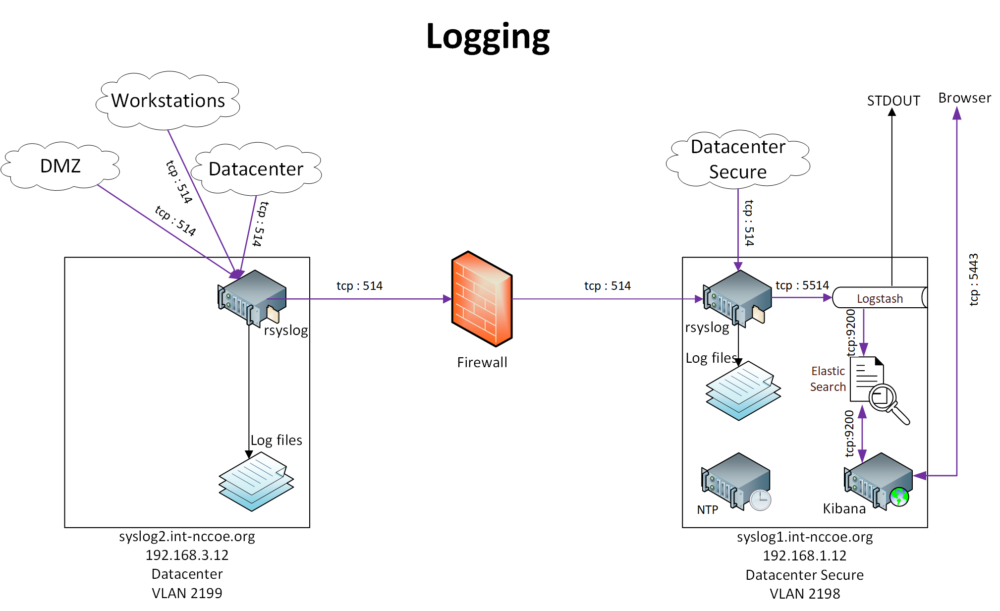
1.5.5.6.1 Prerequisites for Log Aggregation and Correlation Services
In accordance with the logging architecture above, the TLS lab utilized the hosts below. Both hosts must be configured with Fedora, based on the OS configuration guidance in Section 1.5.2.2.2. Configure both servers with rsyslog.
syslog1.int-nccoe.org
syslog2.int-nccoe.org
Logstash requires Java 8 or Java 11.
1.5.5.6.2 Remote System Logging Services
Rsyslog is an open-source software utility used on UNIX and UNIX-like computer systems for forwarding log messages in an IP network.
To install rsyslog use the command
dnf install rsyslog
For more information on configuring rsyslog, refer to the following link:
1.5.5.6.3 Elasticsearch Installation and Configuration
Elasticsearch is a search engine based on the Lucene library. It provides a distributed, multitenant-capable full-text search engine with an http web interface and schema-free JavaScript Object Notation documents. Elasticsearch is developed in Java.
To install and configure Elasticsearch, please refer to the following link:
1.5.5.6.4 Kibana Installation and Configuration
Kibana is an open-source data visualization plug-in for Elasticsearch and provides visualization capabilities on top of the content indexed on an Elasticsearch cluster. Users can create bar, line, and scatter plots (or pie charts) and maps on top of large volumes of data.
To install and configure Kibana, please refer to the following link:
1.5.5.6.5 Logstash Installation and Configuration
Logstash is an open-source, server-side data processing pipeline that ingests data from a multitude of sources simultaneously, transforms it, and then sends it to the user’s favorite stash.
To install and configure Logstash, please refer to the following link:
1.5.6 DevOps Services
The NCCoE undertook a limited DevOps demonstration using a Kubernetes cluster. This limited demonstration included basic DevOps functionality for automated system and application deployment.We showed automated management of TLS server certificates in a container-based environment by useing Kubernetes with Docker, NGINX, and Jetstack Cert-Manager
1.5.6.1 Kubernetes Installation and Configuration
Instructions for installing Kubernetes are available at the following link:
We installed Kubernetes on three CentOS Linux systems (cluster1, cluster2, cluster3.int-nccoe.org).
1.5.6.2 Weave
We used Weave as the virtual network to facilitate communications between the Kubernetes primary and nodes. Instructions for installing Weave can be found at the following link:
1.5.6.3 Docker Installation and Configuration
We used the community edition of Docker with Kubernetes. Instructions for installing Docker on CentOS are found at the following link:
1.5.6.4 Jetstack Cert-Manager Installation and Configuration
We installed Jetstack Cert-Manager on Kubernetes with the necessary components to request certificates from Venafi TPP by using the following command:
kubectl apply -f https://raw.githubusercontent.com/jetstack \\

/cert-manager/venafi/contrib/manifests/cert-manager/with-rbac.yaml
This automatically created a namespace named “cert-manager,” which we used for the rest of our configuration.
1.5.6.5 NGINX Installation and Configuration
NGINX was used as the web server and ingress on Kubernetes. Certificates were associated with the NGINX ingress. Instructions for installing and configuring NGINX on Kubernetes are found at the following link:
In our implementation, we installed NGINX on Kubernetes with the following command into the cert-manager namespace.
kubectl create deployment nginx –image=nginx -n cert-manager
We then created a service for NGINX by using the following command:
kubectl create service nodeport nginx –tcp=80:80 -n cert-manager
2 Product Installation and Configuration Guides
This section of the practice guide contains detailed instructions for installing and configuring all of the TLS collaborator products used to build an instance of the example solution. Each major subsection (2.1, 2.2, 2.x) is dedicated to a collaborator’s product capability. Within each product capability section, descriptions of each product capability align with a Day 0, Day 1, and Day N concept. It is important to note that each day builds on the previous day(s) for prerequisites, and each collaborator capability does the same. So, if the implementer’s intent is to fully replicate the TLS lab environment, then following the order of days and component installations will help make that endeavor more successful.
Day 0 provides how-to guidance from a first-day installation perspective. It is assumed the implementer is getting acclimated with the collaborator product. The implementer should complete all prerequisites, which include complete installations of other collaborator products in some instances or the Supporting Architecture described in Section 1.3. The expectation is for only basic crucial configuration functions to get the system up and running. Otherwise, other configurations should be executed on Day 1, or there may be issues with prerequisites that have not been executed.
Day 1 assumes all Day 0 activities have been completed, including all prerequisites. Expected activities include how-to guidance on more advanced security configuration of functioning in the TLS environment. Day 1 also assists the implementer with configuration guidance for integration with any other collaborator product capabilities.
Day N assists the implementer with all necessary configurations and integrations of systems that help facilitate ongoing security management and maintenance. In most cases, the minimum Day N configuration and integration include security event audit and event logging for TLS systems. In all cases, there are variations of services and offerings, which each collaborator describes in their respective sections.
2.1 Product Installation Sequence (Example Build)
Figure 2-1 shows the dependencies among components deployed for the example build. A solid line with a single arrow signifies hard dependencies. The component from which the arrow points should be installed before the component to which the arrow points. This facilitates phased and secure deployment. A dashed line with a double arrow indicates that integration between the components is not dependent on the installation sequence (i.e., either component can be installed first).
Figure 2‑1 Overview of Dependencies Among Components Deployed for the Example Build
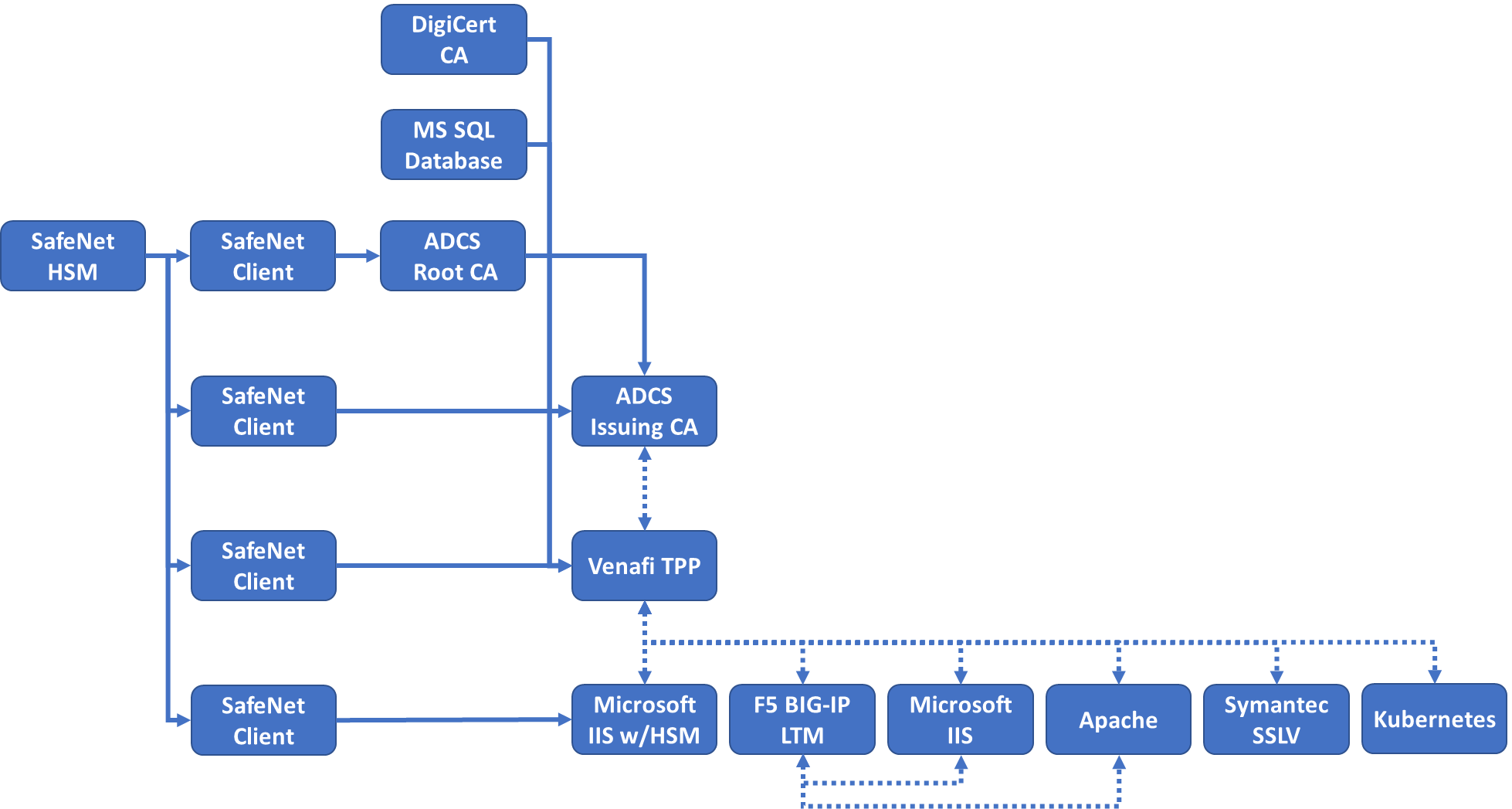
2.2 Thales TCT Luna SA 1700 Hardware Security Module
HSMs are specialized hardware devices dedicated to maintaining the security of sensitive data throughout its life cycle. HSMs provide tamper-evident and intrusion-resistant protection of critical keys and other secrets, and off-loading of processing-intensive cryptographic operations. By performing cryptographic operations within the HSM, sensitive data never leaves the secure confines of the hardened device.
The Thales TCT Luna SA for Government is a network-attached HSM with multiple partitions to effectively provide a many-in-one solution to multiple tenants—each with its own security officer management credentials. Depending on security needs, the Luna SA can be used with or without a secure personal identification number entry device (PED) for controlling management access to the HSM partitions. Utilizing the PED takes the HSM from a Federal Information Processing Standards (FIPS) 140-2 [D1] Level 2 certified device to Level 3. The Luna SA also comes in two performance models: the lower performance 1700, and the high-performance 7000 for transaction-intensive use cases.
2.2.1 Day 0: Product Installation and Standard Configuration
2.2.1.1 Prerequisites
2.2.1.1.1 Rack Space
Installation of the HSM requires rack space with the following characteristics:
standard 1u 1 gin rack mount chassis
dimensions: 19” x 21” x 1.725” (482.6 millimeters [mm] x 533.4 mm x 43.815 mm)
weight capacity: 28 pounds (lb) (12.7 kilograms [kg])
input voltage: 100-240 V.50-60 hertz
power consumption: 180 watts (W) maximum, 155 W typical
temperature: operating 0 degrees Celsius (C)–35 degrees C, storage 20 degrees C–60 degrees C
relative humidity: 5% to 95% (38 degrees C) noncondensing
2.2.1.1.2 Networking
One of two approaches to networking may be used. The steps for the commands in this document assume the NCCoE’s laboratory networking environment will be replicated. An organization may also opt to use its own network settings. In either case, the following Luna SA HSM appliance parameters information will be needed:
IP address that will be assigned to this device (Static IP is recommended)
Host name for the HSM appliance (registered with network DNS)
a domain name where the device will reside
default gateway IP address
DNS Name Server IP address(es)
Search Domain name(s)
device subnet mask
Ethernet device (use eth0, which is the uppermost network jack on the HSM appliance back panel, closest to the power supply, and labeled 1
 )
)
The network must be configured for optimal use of Luna appliances. The following bandwidth and latency recommendations are optimal for performance settings:
bandwidth
minimum supported: 10 megabit (Mb) half-duplex
recommended: at least 100 Mb full duplex—full gigabit Ethernet is supported
Note: Ensure the network switch is set to AUTO negotiation, as the Luna appliance negotiates at AUTO. If the network switch is set to use other than automatic negotiation, there is a risk that the switch and the Luna appliance will settle on a much slower speed than is actually possible in the organization’s network conditions.
network latency
maximum supported: 500 milliseconds (ms)
recommended: 0.5 ms
2.2.1.1.3 Unpacking the Appliance
Follow this checklist to verify that all of items required for the installation are in hand.
Qty |
Item |
1 |
Luna SA HSM appliance |
2 |
power supply cord (one for each power supply; style to suit country for which was ordered) |
1 |
null modem serial cable |
1 |
Universal Serial Bus 2.0 to RS232 serial adapter |
1 |
Set of:
- 2 front mounting brackets with screws
- 2 side bracket guides
- 2 sliding rear brackets (Fit into the guides for rear support adjustable positioning.)
|
1 |
client/software development kit (SDK) software |


2.2.1.2 Rack-Mount the Appliance
Install and adjust rails and brackets to suit the equipment rack.

Mount the appliance in the equipment rack. Alternatively, ignore the rails and mounting tabs, and rest the Luna SA appliance on a mounting tray or shelf suitable for the organization’s specific style and brand of equipment rack.
CAUTION: Support the weight of the appliance until all four brackets are secured.

Insert the power (a) and network (b) cables at the rear panel. For proper redundancy and best reliability, the power cables should connect to two completely independent power sources.
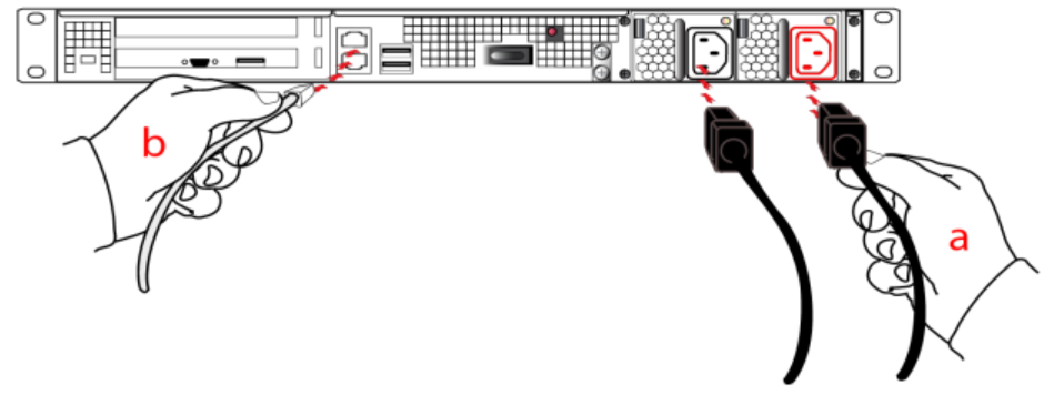
Press and release the Start/Stop switch, on the rear panel.
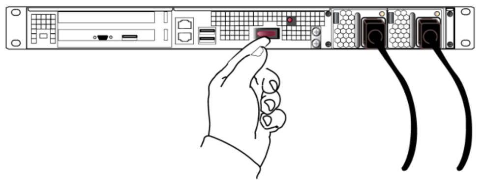
2.2.1.3 Initial Appliance Configuration
This section describes the process to prepare the new HSM Server and one client system for operation with the application. It includes the following steps:
process for first-time login and changing passwords
verify and set the date and time
configure HSM appliance’s IP and network parameters (using static or Dynamic Host Configuration Protocol [DHCP]. In general, we strongly recommend against using DHCP for HSM appliances.)
make network connections (To make a network connection, refer to Section 2.2.1.1.2.)
HSM initialization process
restart services so configuration changes can take effect
2.2.1.3.1 Process for First-Time Login and Changing Passwords
To perform initial login to the HSM appliance, connect a serial cable to serial port on the front of the appliance.
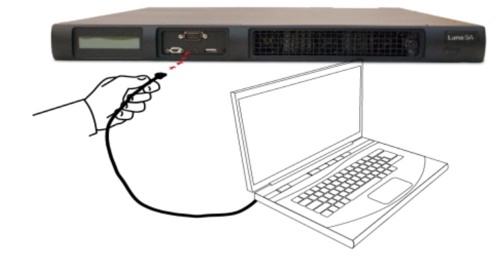
On the management laptop, open the PuTTY application and select a Connection type of Serial with a Speed of 115200.
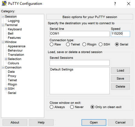
Navigate to the Serial Category on the bottom left side of the window.
Configure the serial connection to support the SSL Visibility Appliance’s console speeds by selecting the following options:
Speed (baud): 115200
Data bits: 8
Stop bits: 1
Parity: None
Flow control: None
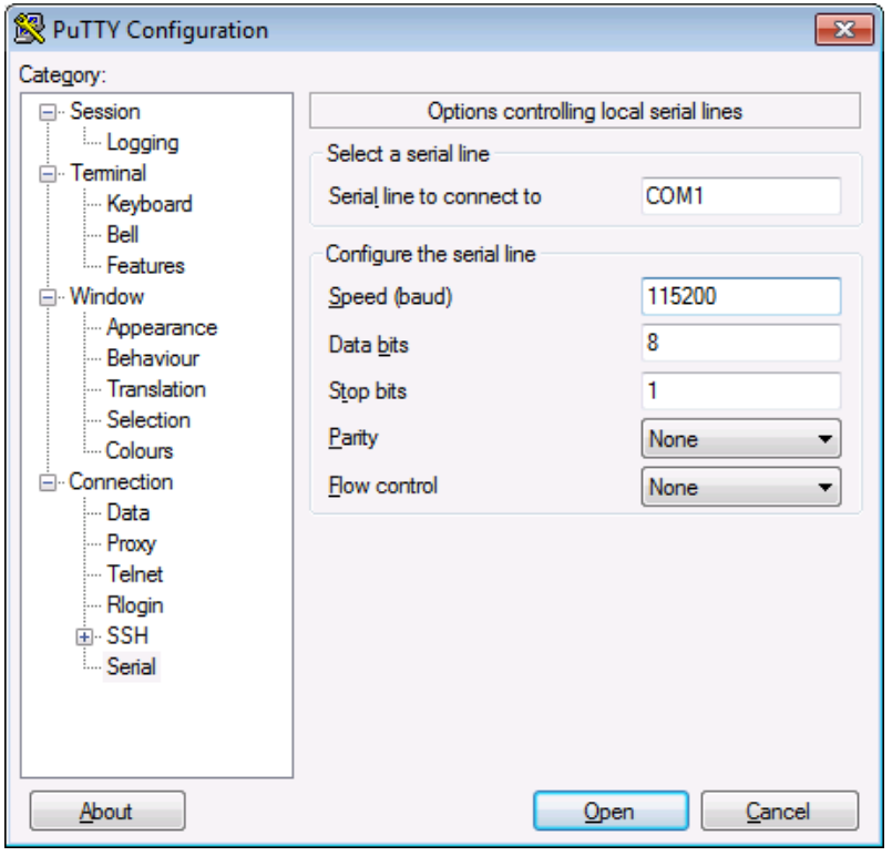
Log in to the appliance by using the default credentials of:
username: bootstrap
password: bootstrap
For security purposes, the user is immediately prompted to change the factory-default password for the admin account.
[localhost] ttyS0 login: admin Password: You are required to change your password immediately (root enforced) Changing password for admin (current) UNIX password:
  A valid password should be a mix of upper and lower case letters, digits, and other characters. You can use an 8 character long
  password with characters from at least 3 of these 4 classes.
  An upper case letter that begins the password and a digit that
  ends it do not count towards the number of character classes used.

Enter new password:
   Re-type new password:
Luna SA 5.4.0-14 Command Line Shell - Copyright (c) 2001-2013 SafeNet, Inc. All
   rights reserved.
Command Result: 0 (Success)
   lunash:>
The above represents a local serial connection; text will differ slightly for a Secure Shell (SSH) connection.
Note: The username and passwords are case-sensitive.
Note: To protect the HSM appliance and its HSM from vulnerabilities due to weak passwords, new passwords must be at least eight characters in length and must include characters from at least three of the following four groups:
– lowercase alphabetic (abcd…xyz)
– uppercase alphabetic (ABCD…XYZ)
– numeric (0123456789)
– special (nonalphanumeric, #*@#$%&…)
Note: Login must occur within two minutes of opening an administration session, or the connection will time out.
2.2.1.3.2 Date and Time
To configure the HSM’s date and time, perform the following steps:
Verify the current date and time on the HSM Server.
At the lunash prompt, type the command:
lunash:>status dateIf the date, time, or time zone is incorrect for the location, change them by using the
lunash sysconfcommand. For example:lunash:>sysconf timezone set Canada/Eastern Timezone set to Canada/Eastern- Use sysconf time to set the system time and date <HH:MM YYYYMMDD> in the format shown. Note that the time is set on a 24-hour clock (00:00 to 23:59).
lunash:> sysconf time 12:55 20190410 Sun April 10 12:55:00 EDT 2019 Optionally to configure Network Time Protocol (NTP), use the following command:
lunash:>sysconf ntp addserver 192.168.1.12Activate the NTP service with the following command:
sysconf ntp enable
2.2.1.3.3 Network Configuration
- Use the network show command to display the current settings and to see how they need to be modified for the network.
lunash:> net show
    Hostname:         HSM
    Domain:           int-nccoe.org


    IP Address (eth0): 192.168.1.13
HW Address (eth0): 00:15:B2:AB:D6:D6
    Mask (eth0): 255.255.255.0
Gateway (eth0):   192.168.1.1

Name Servers: 192.168.1.6
    Search Domain(s): <not set>

Kernel IP routing table
Destination Gateway Genmask Flags Metric Ref Use Iface
Link status
  eth0: Configured
        Link detected: yes
  eth1: Configured
Link detected: no
Command Result : 0 (Success)
lunash:>
Use
network hostnameto set the host name of the HSM appliance (use lowercase characters).lunash:>network hostname HSMUse
network domainto set the name of the network domain in which the HSM Server (appliance) is to operate.lunash:>net domain int-nccoe.orgUse
network dns add nameserver to set the Nameserver IP Address (address for the local name server).
``lunash:>
net dns add nameserver 192.168.1.6Use net dns add searchdomain`` to set the DNS Search Domain (the search list to be used for host name lookups).
lunash:>net dns add searchdomain int-nccoe.orgUse
network interfaceto change network configuration settings. All of thenetwork interfaceparameters are required for the IP setup of the Ethernet device and must be set at the same time for the HSM appliance to connect with the network.[HSM] lunash:>net interface -device eth0 -ip 192.168.1.13 -netmask 255.255.255.0 -gateway 192.168.1.1View the new network settings with network show.
lunash:>network show
2.2.1.3.4 Generate a New HSM Server Certificate
Although the HSM appliance came with a server certificate, good security practice dictates that a new one be generated.
Use
sysconf regenCertto generate a new server certificate:
lunash:> sysconf regenCert 192.168.1.13
WARNING !! This command will overwrite the current server certificate and private
key.
All clients will have to add this server again with this new certificate.
If you are sure that you wish to proceed, then type 'proceed', otherwise type
'quit'
> proceed
Proceeding...
'sysconf regenCert' successful. NTLS must be (re)started before clients can connect.
Please use the 'ntls show' command to ensure that NTLS is bound to an appropriate network device or IP address/hostname for the network device(s) NTLS
should be active on. Use 'ntls bind' to change this binding if necessary.

Command Result: 0 (Success)
lunash:>
2.2.1.3.5 Bind the Network Trust Link Service
From the factory, the network trust link service (NTLS) is bound to the loop-back device by default. To use the appliance on the network, bind the NTLS to one of the two Ethernet ports— ETH0 or ETH1—or to a host name or IP address. Use the ntls show command to see current status.
Use ntls bind to bind the service:
lunash:>\ **ntls bind eth0 -bind 192.168.1.13**
Success: NTLS binding hostname or IP Address 192.168.1.13 set.
NOTICE: The NTLS service must be restarted for new settings to take effect.
If you are sure that you wish to restart NTLS, then type 'proceed', otherwise type 'quit'
> proceed
Proceeding...
Restarting NTLS service...
Stopping ntls:                                             [  OK  ]
Starting ntls:                                             [  OK  ]
Command Result : 0 (Success)
[myluna] lunash:>ntls show
NTLS bound to network device: eth0  IP Address: "192.168.1.13" (eth0)
Command Result : 0 (Success)
NOTE: The “Stopping ntls” operation might fail in the above example, because NTLS is not yet running on a new HSM appliance—ignore this message. The service restarts regardless if the stop was needed.
2.2.1.3.6 Enabling Federal Information Processing Standards 140-2 Mode
In many areas of the information security industry, validations against independent or government standards are considered a desirable or essential attribute of a product. NIST’s FIPS 140 is the pre-eminent standard in the field of cryptography. Enabling FIPS 140-2 [D1] ensures the HSM uses strong cryptographic modules in its operations.
Log in to the APPLIANCE management console (LunaSH) as admin.
SSH into the APPLIANCE
Use these credentials: Username: admin Password: ****YOUR admin PASSWORD****
Check if FIPS 140 mode is enabled.
Command:
hsm showIn the results, look for “The HSM is in FIPS 140-2 approved operation mode.” If this is seen, then stop: FIPS 140-2 mode is already enabled on the HSM. Otherwise, continue.
Log in to the admin role.
Command:
hsm loginPassword: ****YOUR admin PASSWORD****
View HSM Capabilities and Policies.
Command:
hsm showPoliciesIn the results, look for “Allow non-FIPS algorithms” and record its value and code.
Edit HSM Capabilities and Policies.
Command:
hsm changePolicy -policy <code> -value <desired_value>hsm changePolicy -policy 12 -value 1When prompted type:
proceed
Confirm FIPS 140 mode is enabled.
Command:
hsm showIn the results, look for “The HSM is in FIPS 140-2 approved operation mode.” If this is seen, then stop: FIPS 140-2 mode is already enabled on the HSM. Otherwise, further investigation is required.
2.2.1.4 HSM Initialization
In this section, initialize the HSM portion of the Luna appliance and set any required policies. In normal operations, these actions are performed when first commissioning the Luna appliance.
2.2.1.4.1 Initialize a Password-Authenticated HSM
To initialize the HSM, type the following command:
hsm -init -label HSM

    [HSM] lunash:> hsm -init -label HSM
    > Please enter a password for the security officer
    > ********
    Please re-enter password to confirm:
    > ********
    Please enter the cloning domain to use for initializing this
    HSM (press <enter> to use the default domain):
    > ********
    Please re-enter domain to confirm:
    > ********
    CAUTION:  Are you sure you wish to re-initialize this HSM?
    All partitions and data will be erased.
    Type 'proceed' to initialize the HSM, or 'quit'
    to quit now.
    >proceed
    ‘hsm - init’ successful.
When activity is complete, lunash displays a “success” message.
2.2.2 Day 1: Product Integration Configuration
2.2.2.1 Prerequisites
NTL–This step will need to be completed for each system; refer to Section 2.2.2.2.
ADCS–Windows server needs to be running; refer to guide.
IIS–Windows server needs to be running; refer to guide.
Venafi–must be installed and configured; refer to Section 2.2.2.2.
2.2.2.2 Network Trust Link
This section provides directions to configure a Luna Client to communicate with the network-attached Luna SA HSM. A client may have multiple Luna SA HSMs connected—using a slot designation when referencing an assigned Luna SA. The client also assumes the Luna SA is installed and operational but without a partition created for the new client.
The Luna Client is available in Windows and Linux. For Linux systems, refer to Thales TCT’s Configuring a Network Trust Link documentation. In this document, the necessary commands and screenshots are listed for Windows-based systems.
2.2.2.2.1 Install the Luna Client Software
To install the Luna Client software, perform the following steps:
Log in to Windows as Administrator or as a user with administrator privileges.
Insert the Luna Client Software DVD into the optical drive.
Open a file explorer and navigate to D:\windows\64\
Double-click Luna Client.msi.
Click Next at the welcome screen.
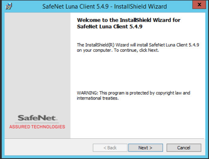
Accept the software license agreement by clicking “I accept the terms in the license agreement” and clicking Next.
In the Choose Destination Location dialogue, accept the default offered and click Next.
Ensure the following options are selected and click Next:
Luna CSP (CAPI)/Luna KSP (CNG)
Luna SDK
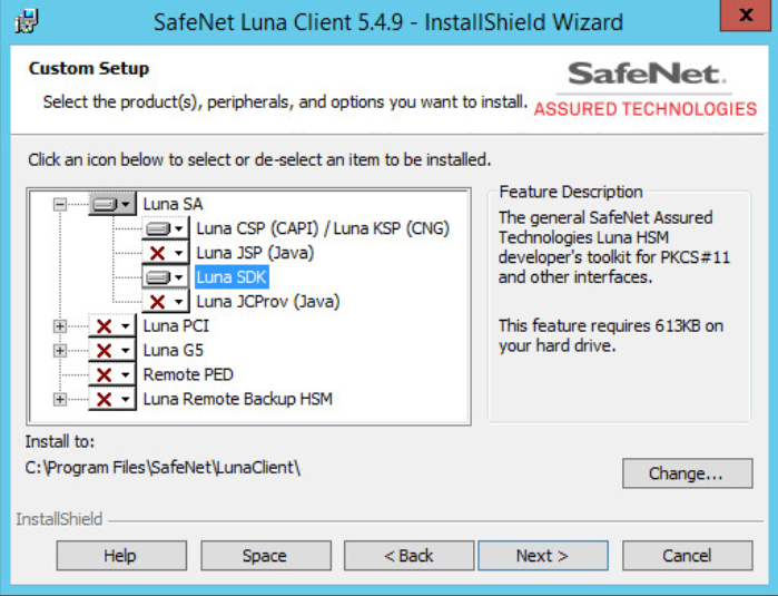
On the Ready to Install page, click Install.
If Windows presents a security notice asking if the user wishes to install the device driver from Thales TCT, click Install to accept.
When the installation completes, click Finish.
2.2.2.2.2 Configure the Luna Client
To establish the NTL, first create a client certificate, and then the client and server certificates are exchanged. The Luna SA appliance is then added as a trusted server in the client.
2.2.2.2.3 Create the Client Certificate
First, create the client certificate by using the Thales TCT VTL command line. This results in a .pem certificate file being created in a \certclient subfolder.
On the client system, from the Windows command environment, run as administrator and navigate to the folder C:Program FilesSafenetLunaClient.

Enter the following command:
vtl createcert –n <client IP address>
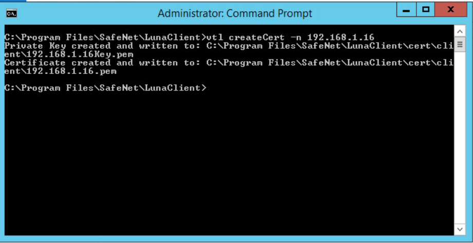
2.2.2.2.4 Transfer the Client Certificate to the Luna SA
Now, transfer the newly created client certificate to the Luna SA by using the PuTTY Secure Copy Protocol (PSCP) or Secure Copy Protocol (SCP) tool.
On the client system using Windows, enter the following command:
pscp “C:\Program Files\SafeNet\LunaClient\cert\client\192.168.1.16.pem” [email protected]:
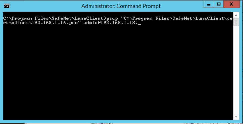
When prompted, enter the appliance administrative password for the Luna SA. The transfer automatically takes place.
2.2.2.2.5 Transfer the Server Certificate from the Luna SA
Using PSCP or SCP, transfer the Luna SA’s server certificate to the client.
On a client system using Windows, enter the following command:
pscp admin@192.168.1.13:server.pem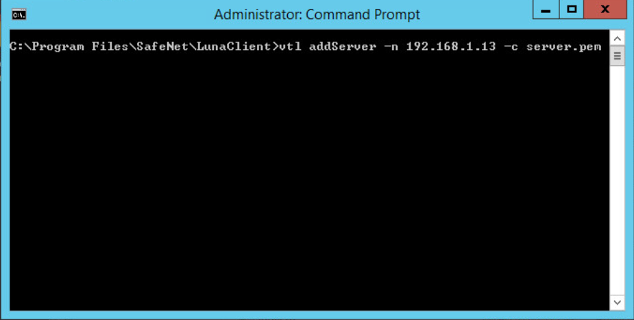
When prompted, enter the administrative password for the Luna SA. The transfer will automatically take place.
2.2.2.2.6 Register the HSM on the Client
The final step in configuring the client is to register the Luna SA’s certificate with the client.
On a client system, enter the following command:
vtl addServer -n <HSM IP Address> -c server.pem
At this point, the client is fully configured and ready to establish a secure link with the HSM.
2.2.2.2.7 Create a Partition (Password Authentication)
Connect into the HSM via SSH or Serial.
At the
lunash:>prompt on the Luna SA, enter the following command:partition create –partition <partition name> -domain <domain name>
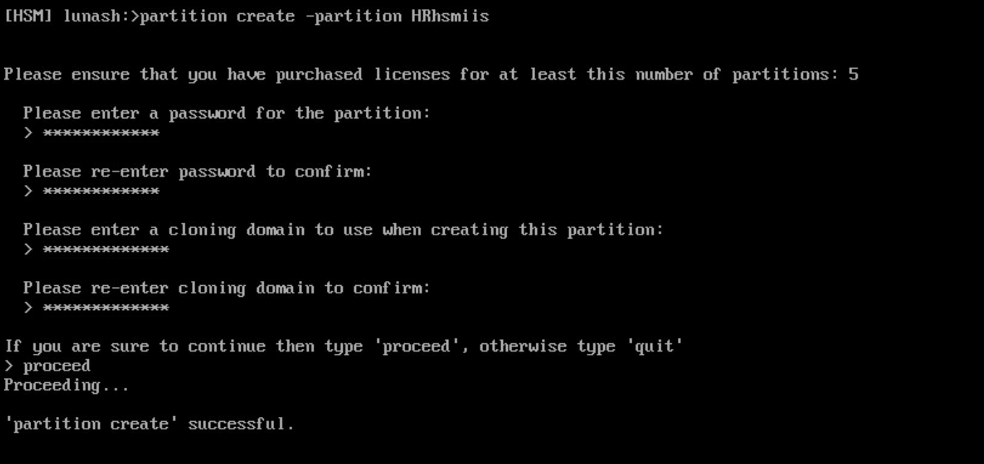
When prompted, enter and re-enter to confirm the partition password.
Enter
proceedwhen prompted.
2.2.2.2.8 Register the Client on the HSM and Assign It to a Partition
Register the client on the HSM and assign it to a partition. Because the HSM was previously created and the client certificate was transferred to it, the HSM can find the certificate file based on the IP address. Assign a name for the client for easy recognition.
On the Luna SA, enter the following command to register the client:
client register –client HRhmsiis -ip 192.168.1.16
On the Luna SA, enter the following command to assign the client to the previously created partition.
client assignPartition -client <client name> -partition <partition name>
On the Luna SA, enter the following command to verify the client is assigned to the proper partition.
client show -client <client name>
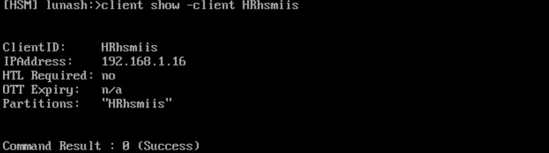
At this point, the HSM is configured, and in the next section, the user will return to the client to verify connectivity and the ability to request cryptographic operations from the client.
2.2.2.2.9 Verify the Network Trust Link
Return to the client and verify it can view the Luna SA and its associated slot and partition. Run the Multitoken2 utility to verify the client can request cryptographic operations from the HSM.
2.2.2.2.10 Verify the Luna SA in Client Server Lists
Verify the Luna SA is in the client’s server lists.
On the client system, from the Windows command environment run as administrator, navigate to the folder C:\Program Files\Safenet\LunaClient.
On the client system, enter the following command and verify the Luna SA is in the list of servers:
vtl listservers

2.2.2.2.11 Verify the Slot and Partition
Verify the slot and the assigned HSM partition can be seen.
On the client system using either Windows and Linux, enter the following command to verify the Luna SA slot and partition are known to the client:
vtl verify
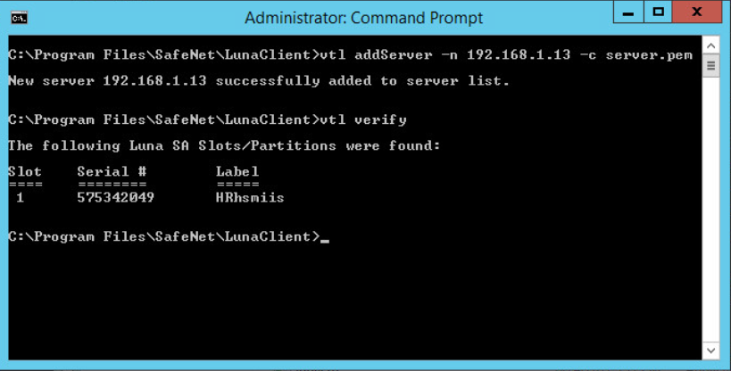
Should this verification fail, check the times on the client and HSM to ensure they are set properly.
2.2.2.2.12 Request Cryptographic Operations on the HSM
Request an actual crypto operation on the HSM to verify full functionality. The Multitoken utility to use is described in the Luna SA product documentation.
On the client system, enter the following command:
multitoken2 –mode rsasigver –key 1024 –slots 1,1,1,1,1When prompted, if continuing, enter y.
Enter the partition password when prompted. The test will begin.
Press the Enter key to terminate the test after verifying that RSA signatures were successfully performed in the statistics table.
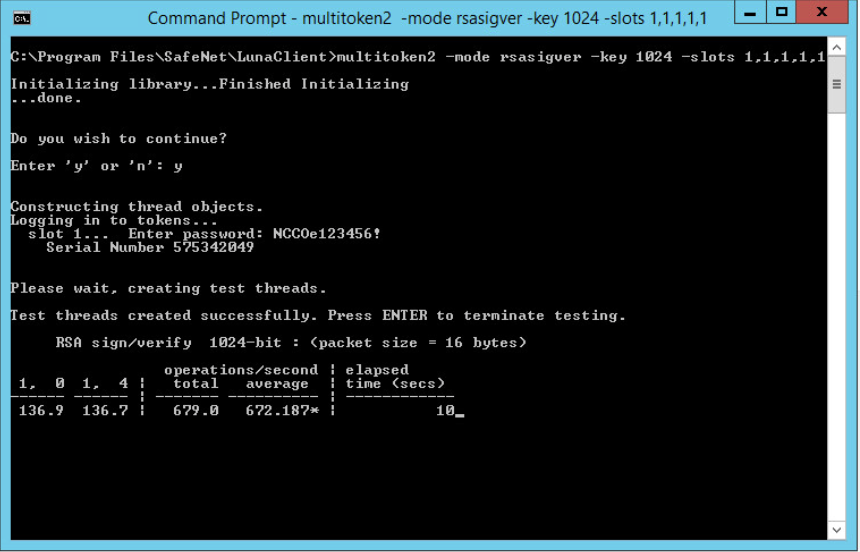
2.2.2.3 ADCS Integration Configuration
This section provides the necessary steps for configuring an ADCS CA to use the Thales TCT Luna SA 1700 HSM for Government, to secure the CA’s private key. This section assumes the Luna HSM client has been installed and configured, as detailed in Section 2.2.1.
Perform the following steps:
Verify the Network Trust Link (NTL) between the Windows Server and the HSM.
Register the Key Storage Provider (KSP) on the Windows Server.
Add the CA role.
Verify the private key for the CA was created on the HSM.
2.2.2.3.1 Prerequisites
To configure Microsoft CA to use the Luna HSM, the following prerequisites must be met:
The Thales TCT Luna HSM is installed and operational.
The Thales TCT Luna Client is installed on the Windows Server where the CA is being added.
The NTL is established between the Luna Client and the Luna HSM. If not, see Section 2.2.2.2.
2.2.2.3.2 Verify the HSM Configuration
Verify the HSM client configuration prior to proceeding by following the steps below:
Open a Command Prompt as Administrator, and change into the Luna Client directory, typically C:\Program Files\SafeNet\LunaClient\
Execute the command
VTL.exeverify to check that the client is configured correctly and the partition is visible. Slot/Partition information should be displayed in response.
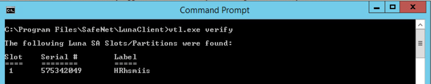
Execute the command
cmulist to see the list of current objects on the HSM, and enter the password when prompted. If nothing has been created on the partition, this list will be blank. Once the CA is configured, the keys created on the HSM are listed.
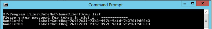
2.2.2.3.3 Register the Key Storage Provider
Beginning with Windows Server 2008, the older CryptoAPI CSP has been superseded by the newer CNGKSP. The Luna Client installation includes a utility to register the Thales TCT HSM for Government as a KSP for use in Windows applications. To register, follow these instructions:
Open Windows Explorer, browse to the KSP folder in the Luna Client installation folder, and double-click on the KSPConfig.exe utility.
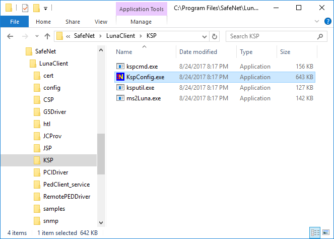
Double-click on Register Or View Security Library, then click Browse.
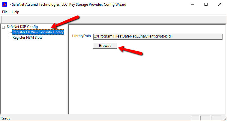
Browse to the Luna Client folder, select cryptoki.dll, and click Open.
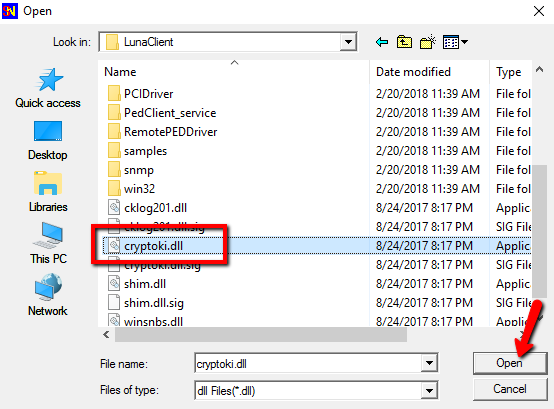
Click on Register to complete the library registration.
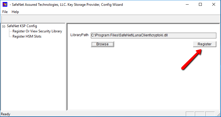
Double-click Register HSM Slots on the left to open the slot registration page. Select the Administrator account and the Domain for the user that will be configuring the CA role. For a server joined to a domain, this should be a Domain or Enterprise Admin account rather than the local machine Administrator. Select the slot for the HSM, enter the Slot Password, and click Register Slot.
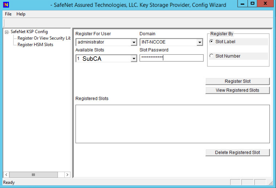
Repeat the slot registration for the user SYSTEM with Domain NT AUTHORITY, and click Register. This is the account used for the CA service—it must also have access to the HSM.
Verify the registration by selecting user and domain and clicking View Registered Slots.
2.2.2.3.4 Add CA Role
For instructions on CA installation and configuration, refer to Section 1.5.3.3.2 on root CAs.
2.2.2.3.5 Verify the Successful Integration on the HSM
As a final step, verify the private key and the public key are stored on the HSM.
Open a command prompt and change to the Luna Client directory, typically C:\Program Files\SafeNet\LunaClient.
Run cmu list to verify the private and public keys for the CA are present on the HSM. They are represented by two “handles.”
The screenshot below shows running the cmu list command before configuring the CA and then after the configuration has been completed.
This completes integration of the Thales TCT Luna SA 1700 HSM for Government with Microsoft Active Directory Certificate Services.
2.2.2.4 IIS Integration Configuration
This section provides the steps necessary to integrate the Microsoft IIS web server and the Thales TCT Luna SA 1700 HSM. The benefit of the integration is that the root private key for IIS is stored in a hardened, FIPS 140-2-certified device.
The following steps explain how to register the Thales TCT Luna SA 1700 HSM as a KSP to store the root certificate’s private key in the HSM.
2.2.2.4.1 Prerequisites
IIS is installed or ready to be installed. The firewall rules may need to be edited to allow https access (typically port 443) and optionally block http (port 80).
If mutual authentication is being performed, the trusted CA’s certificate has been installed.
2.2.2.4.2 Register the Luna KSP
For IIS integration, two accounts need access to the HSM. First, the DOMAINAdministrator account is used for setting up the server—creating the certificate request and installing the certificate. Second, the NT AuthoritySystem account is used by the server to start the IIS service. The KSPConfig utility is used to register the HSM as a KSP for these accounts.
Navigate to the KSP directory under the Luna installation directory, which is typically C:\ProgramFiles\SafeNet\LunaClient.
Run KspConfig.exe to launch the wizard.
When the wizard launches, double-click Register Or View Security Library on the left side of the pane, and then click the Browse button on the right.
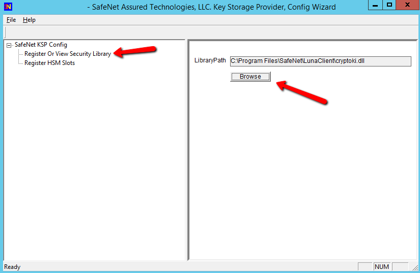
Browse to and select the cryptoki.dll library in the Luna Client directory.
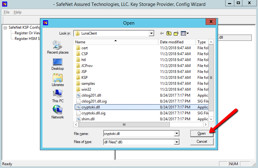
Having selected the dll, click the Register button. The message “Success registering the security library!” displays.
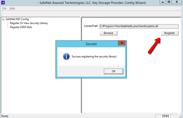
Double-click Register HSM Slots on the left side of the pane.
Verify the correct User and Domain are selected (the Administrator account on the server) and slot is selected (can be registered by slot label or slot number), and enter the Slot Password (HSM partition password).
Click Register Slot to register the slot for that User/Domain. Upon successful registration, a message “The slot was successfully and securely registered” displays.
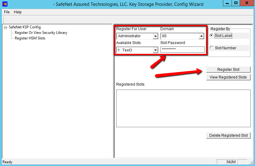
Repeat the steps above to register the slot for the User SYSTEM and Domain NT AUTHORITY.
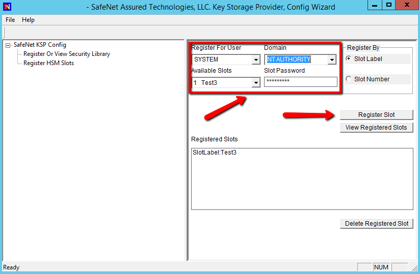
To verify the registered slot, select a User/Domain, and click the View Registered Slots button.
2.2.2.4.3 Setup Synopsis
Verify the NTL between the server and the HSM.
Register the HSM as a KSP.
Install IIS and configure it to use an HSM.
Create a certificate request for IIS, and get it signed.
Install the signed certificate.
Bind the certificate to the web server.
2.2.2.4.4 Install Microsoft IIS
The next step is to install the Web Server (IIS) role by using Server Manager. There are no special considerations surrounding the IIS integration with an HSM. Please follow the installation and configuration steps in Section 1.5.5.2.
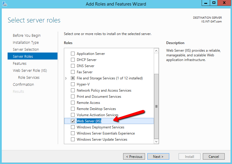
2.2.2.4.5 Create and Install a Certificate for IIS
IIS will need a certificate installed that has been signed by a trusted CA. This involves creating a certification signing request (CSR), then the CA signs it and installs it back in the server. IIS Manager provides an easy way for creating a CSR, but it cannot be used when a key is generated on an external HSM. Instead, use a Microsoft command line utility.
Clients attempting to securely connect to the web server will see an alert if the fully qualified domain name (FQDN) in the Common Name (CN) field (or on more recent browsers, the FQDN in the Subject Alternate Name field) does not match the uniform resource locator (URL) they are accessing. An alert also occurs if the certificate was not issued by a trusted root CA. For this integration, use the FQDN in the CN and Subject Alternative Name (SAN) fields.
2.2.2.4.6 Create a Certificate Signing Request and Private Key
Instructions follow for using the certreq.exe utility to create the CSR and private key in the HSM.
Create a file called request.inf that will contain the necessary information for the utility to create the CSR. The contents of the file are as follows—only those items in blue italics will vary per the organization’s environment and requirements. The CN in the subject and the dns name in the SAN extension must match the full host name that clients enter as the URL in a web browser.
Copying and pasting the text may insert line breaks or change quotation marks to smart (curly) quotation marks. Ensure that each entry is on a single line and that all quotation marks are standard, straight, and double.
In this document, some entries may appear with line breaks such as the Subject=… and %szOID_ENHANCED_KEY_USAGE… lines, but they must be on a single line. In addition, if using Notepad, change the file type to “all files” so it does not create the file with an extension of .txt. The “hide extensions for known file types” option may need to be disabled in Windows Explorer to verify the file is an .inf file rather than a .txt file. The text of the .inf file follows, as well as an image of the how the file should look.
[Version]
  Signature= "$Windows NT$"

  [NewRequest]
  Subject = "C=US,CN=HRhsm.int-nccoe.org,O=SafeNetAT,OU=TLSLAB,L=Gaithersburg,S=Maryland"
  HashAlgorithm = SHA256
  KeyAlgorithm = RSA
  KeyLength = 2048
  ProviderName = "Safenet Key Storage Provider"
  KeyUsage = 0xf0
  MachineKeySet = True
  [EnhancedKeyUsageExtension]
  OID=1.3.6.1.5.5.7.3.1

[Strings]

szOID_SUBJECT_ALT_NAME2 = "2.5.29.17"
  szOID_ENHANCED_KEY_USAGE = "2.5.29.37"
  szOID_PKIX_KP_SERVER_AUTH = "1.3.6.1.5.5.7.3.1" szOID_PKIX_KP_CLIENT_AUTH = "1.3.6.1.5.5.7.3.2"

[Extensions]
   %szOID_SUBJECT_ALT_NAME2% = "{text}dns=HRhsm.int-nccoe.org"
   %szOID_ENHANCED_KEY_USAGE% =
   "{text}%szOID_PKIX_KP_SERVER_AUTH%,%szOID_PKIX_KP_CLIENT_AUTH%"
Example image of file with correct line breaks:
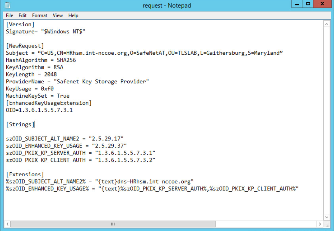
With the information file created, execute the certreq utility to generate a key on the HSM, and the certificate request. The CSR will be output to the file name that the user provides.
certreq.exe –new request.inf <CSR_filename>
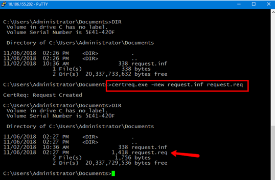
2.2.2.4.7 Get the CSR Signed by a Trusted CA
A trusted CA must sign the generated CSR (example below). The CA authenticates the request and returns a signed certificate or a certificate chain. When the certificate file is received back, save it in the current working directory.
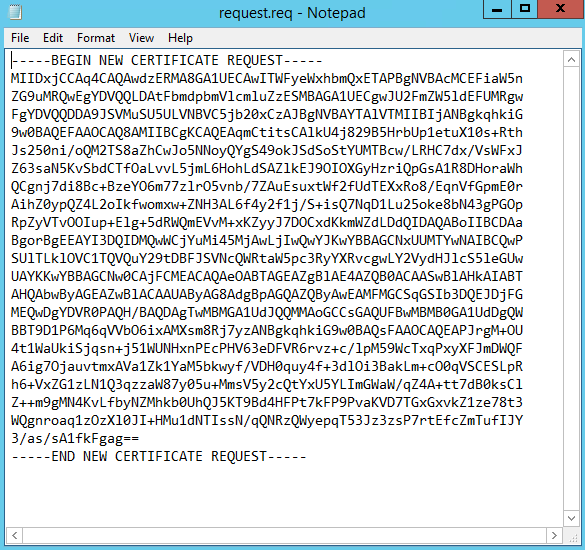
The CSR was signed by using an Enterprise CA. Follow the steps below to create a new template and to sign the certificate request:
Search for and run certsrv.msc, or from Server Manager select Tools > Certification Authority to view the CA. Expand the CA > right-click Certificate Templates > select Manage.
In the Certificate Templates Console, scroll down to find the Web Server template and right-click > select Duplicate Template.

Fill out the various sections of the properties with settings that adhere to the company’s security policies. For this guide, the only thing altered is the Template name in the General tab. This will be the name used when signing the request on the command line.
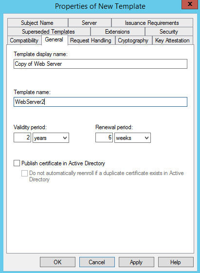
Select the Subject Name tab, and verify that Supply in the request is selected. The FQDN is specified in both the CN and SAN fields in the request file created, and the certificate will use these values.
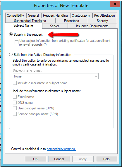
Click OK to finish creating the new template.
Close the Certificate Templates Console > return to the Certificate Authority window.
Click on Action > New > Certificate Template to Issue
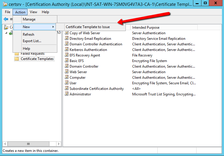
Select the certificate template created > click OK.
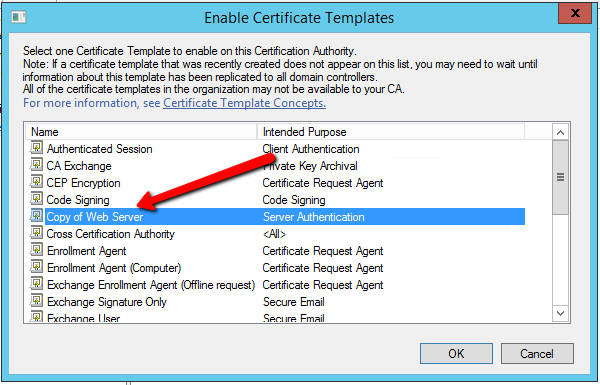
Generate a certificate from the certificate request:
certreq -attrib "CertificateTemplate:<TemplateName>" -submit <certificate request filename>

The user will be prompted to select the CA to use for signing, and a location and file name to save the signed certificate. Once the signed certificate file is created, it can be copied to the IIS server to continue with the integration.
2.2.2.4.8 Install the Signed Certificate
Once the CSR is signed and the signed certificate file is received back, accept and install it by using the certreq utility.
certreq.exe –accept <newcert.crt>
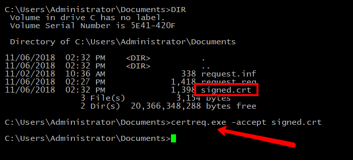
If this step fails, the most common cause is that the issuing CA root certificate is not installed in the server’s certificate store. Verify the issuing CA is trusted, or install the CA certificate into the Local Machine—Trusted Root CA certificate store.
2.2.2.4.9 Bind the Certificate to the IIS Web Server
The final step is to bind the certificate to the IIS web server:
Open the IIS Manager from Start > Administrative Tools > Internet Information Services (IIS) Manager.
Under Sites on the left side of the IIS Manager window, select the desired website.
On the right side of the IIS Manager, click Bindings.
In the Site Bindings window, click Add.
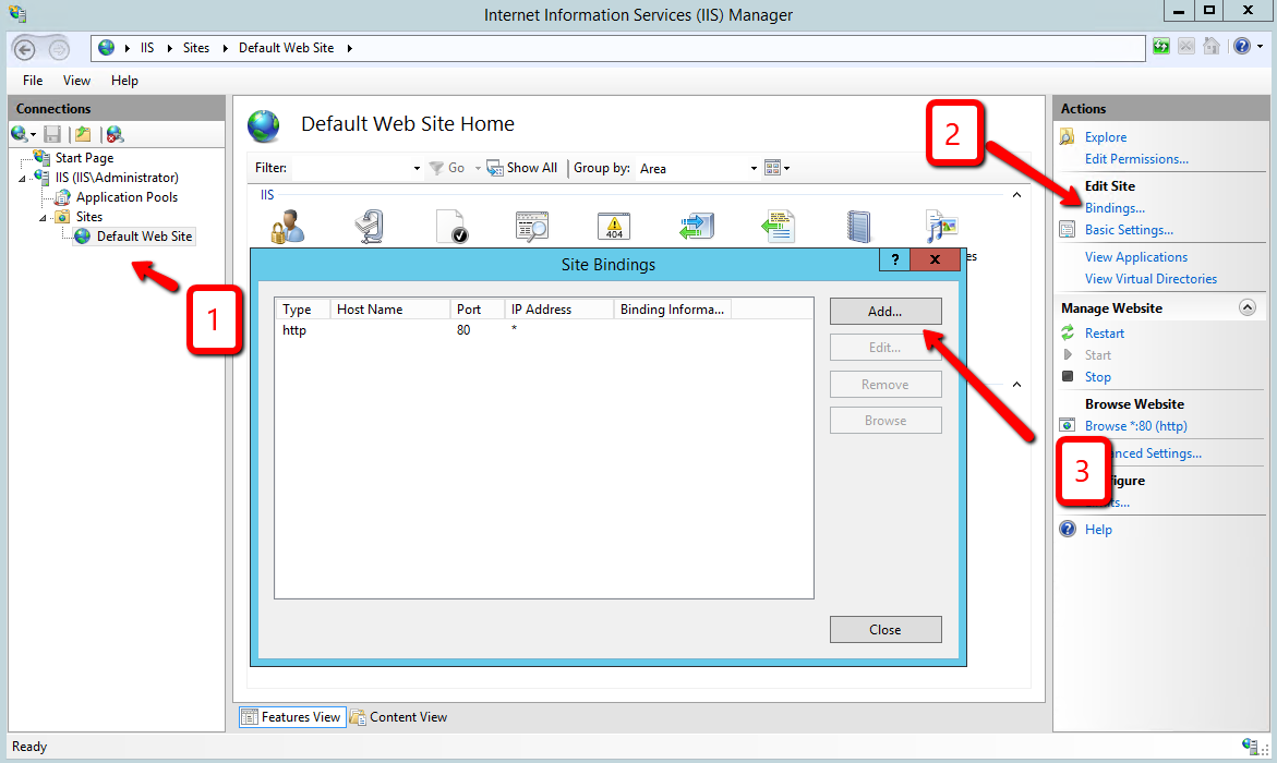
Select the protocol as https.
Select the IP address of the machine running IIS from the IP Address drop-down list, or leave blank to use all available network interfaces.
Enter port 443.

In the SSL certificate: drop-down, select the certificate that was just installed.
Complete the certificate binding in support of SSL/TLS, then click OK.
Verify the connection is working, open a browser, and enter your URL (e.g., https://hrhsm.int-nccoe.org:443). There may be a prompt to accept the certificate for the site. The host name must match the name used in the certificate request and must be registered with the DNS server to resolve the host name to the IP address of the IIS server.
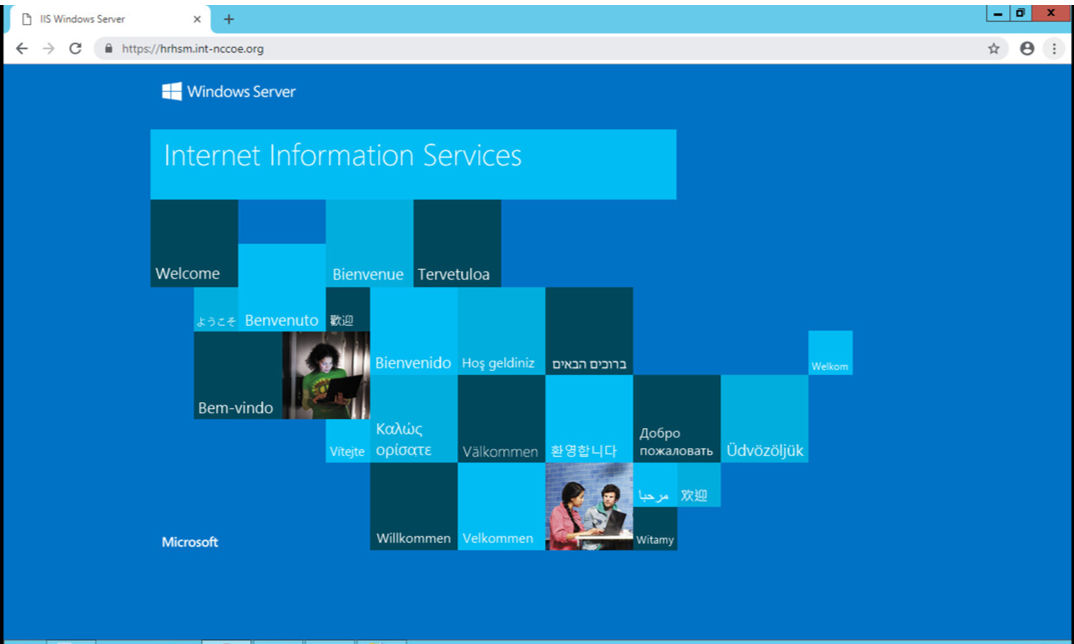
2.2.2.5 Venafi Integration Configuration
This section covers the necessary information to integrate Venafi with the Thales TCT Luna SA 1700 for Government HSM. When integrated with the Luna, Venafi can create and store the primary encryption key used to encrypt and decrypt the Venafi database. In this configuration, the Venafi TPP services will not start unless the key stored in the HSM is accessible. This provides an additional hardened layer of security to protect data in the database.
2.2.2.5.1 Prerequisites
To integrate Venafi with the Luna SA HSM, the following prerequisites must be met:
The Thales TCT Luna HSM is installed and operational.
The Thales TCT Luna Client is installed on the Venafi server.
The NTL is established between the Luna Client and the Luna HSM as described in Section 2.2.2.2.9.
The NTL between the Venafi server and the HSM has been verified.
Venafi has been configured to use the Luna SA HSM.
The primary encryption key was created on the Luna SA HSM and has been verified.
2.2.2.5.2 Verify the Network Trust Link Between Venafi and the HSM
The Luna Client installed on the server enables communication between Venafi and the HSM via a secure connection or an NTL. If the NTL has not been set up during HSM/client installation, reference Section 2.2.2.2 of this guide.
Use the vtl verify command in the installed client directory (typically C:\Program Files\SafeNet\LunaClient) to determine if the connection was established
and that a partition exists on the HSM that the client can access. If no slot and partition are found, the NTL is not established.
The slot number and partition password will be needed when configuring Venafi to use the HSM.
vtl verify
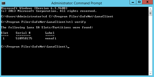
For further configuration between the HSM and Venafi TPP, please reference Section 2.6.13.3.
2.2.3 Day N: Ongoing Security Management and Maintenance
2.2.3.1 Prerequisites
remote system logging server
2.2.3.2 Remote System Logging
Refer to the Luna SA syslog commands to use the remote system logging on any UNIX/Linux system that supports the standard syslog service. Refer to the Luna SA syslog commands under “syslog remotehost” (subcommands “add,” “delete,” and “list”) for more information. The remote host must have User Datagram Protocol (UDP) port 514 open to receive the logging. Refer to the hostʼs OS and firewall documentation for more information.
Type the command below on the Luna SA appliance:
lunash:>syslog remotehost add 192.168.1.12Start syslog with the “-r” option on the receiving or target system to allow it to receive the logs from the Luna SA appliance(s).
2.2.3.3 Audit Logging
With Luna SA, the audit logs can be sent to one or more remote logging servers. Either UDP or Transmission Control Protocol (TCP) protocol can be specified. The default is UDP and port 514.
2.2.3.3.1 UDP Logging
If using UDP protocol for logging:
The following is required in /etc/rsyslog.conf
$ModLoad imudp
$InputUDPServerRun (PORT)
Possible approaches include:
With templates:
$template AuditFile,”/var/log/luna/audit_remote.log”
$syslogfacility-text == ‘local3’ then ?AuditFile;AuditFormat
Without templates:
local3.* /var/log/audit.log;AuditFormat
Dynamic file name:
$template DynFile,”/var/log/luna/%HOSTNAME%.log”
if $syslogfacility-text == ‘local3’ then ?DynFile;AuditFormat
The important thing to remember is that the incoming logs go to local3, and the Port/Protocol that is set on the Luna appliance must be the same that is set on the server running rsyslog.
2.2.3.3.2 TCP Logging
Here is an example to set up a remote Linux system to receive the audit logs by using TCP.
Register the remote Linux system IP address or host name with the Luna SA:
lunash:> audit remotehost add -host 172.20.9.160 -protocol tcp -port 1660
2.3 DigiCert Certificate Authority
2.3.1 Day 0: Installation and Standard Configuration
2.3.1.1 Certificate Prerequisites for Domain Validation and Organization Validation
organization validation–can be an individual or group/team
domain validation process–DNS text (TXT) record validation
must have resolvable FQDN entered in zone file (tls.nccoe.org, app1.tls.nccoe.org)
access to DigiCert’s web-based registration system
account sign-up
2.3.1.2 Standard Configuration
2.3.1.2.1 Account Sign-Up
Start the account sign-up process at https://www.digicert.com/account/signup/.
Complete the Your information, Organization information, and Account information sections.
Read and accept the terms of the Certificate Services Agreement. Check the box to acknowledge acceptance of the terms.
Click the Sign Up button to create a CertCentral account.
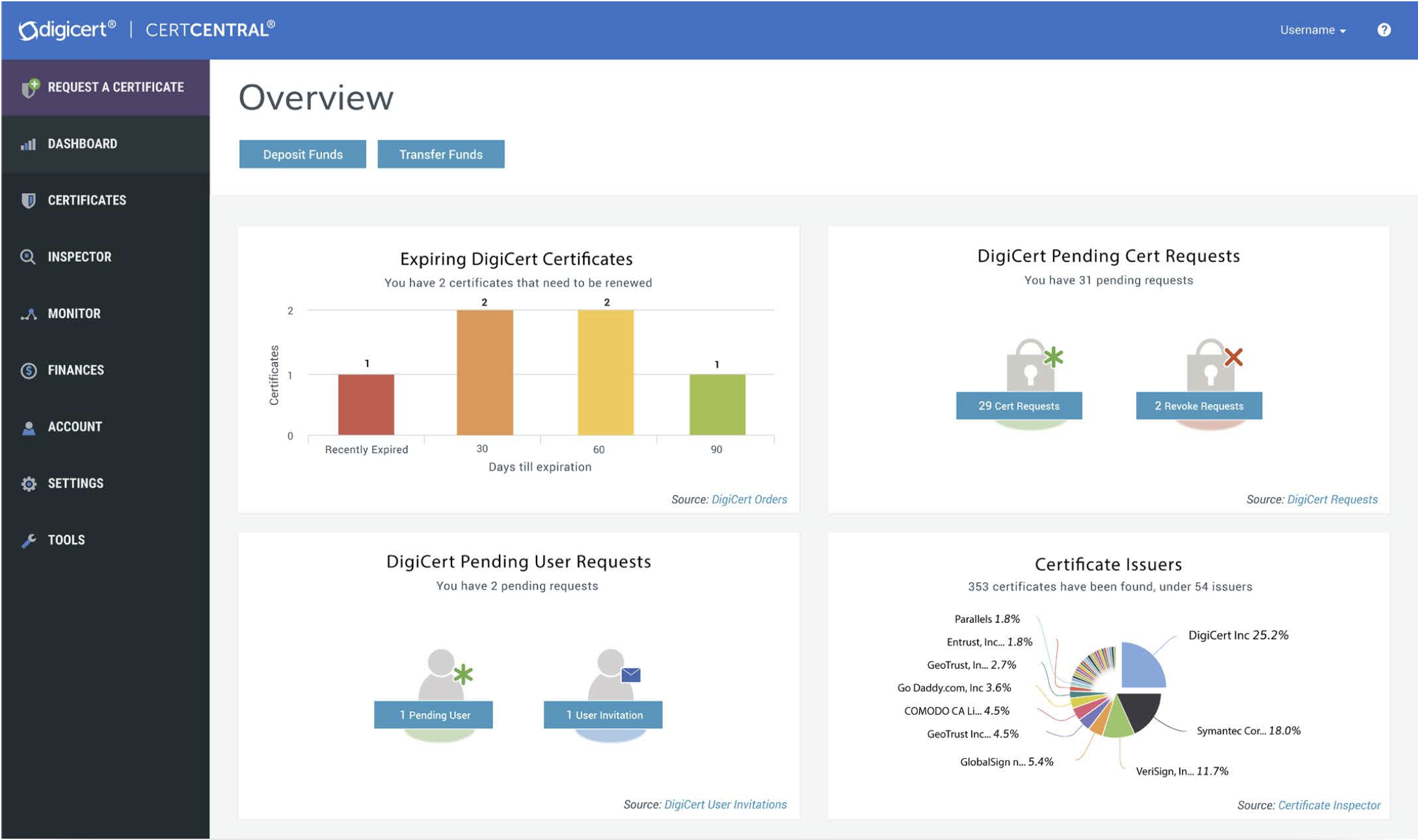
2.3.1.2.2 Language Preferences
Currently, CertCentral supports the following languages:
Deutsch
English
Español
Français
Italiano
Português
한국어
日本語
简体中文
繁體中文
To change the language in the CertCentral account, click the account name at the upper-right side of the screen and select My Profile from the drop-down list.
On the Profile Settings page in the Language drop-down list, select the language preference for the account.
Click Save Changes. The language in CertCentral should now be the same as the one selected.
2.3.1.2.3 Billing Contact
To edit the assigned Billing Contact in the CertCentral account:
In the sidebar menu, click Finances > Settings.
On the Finance Settings page, click Edit under Billing Contact in the right column.
In the Edit Billing Contact window, set or change the contact information.
Click Update Billing Contact to save the change.
2.3.1.2.4 Authentication Settings
Authentication settings allow control over the user login options for the CertCentral account and to set security standards for password requirements and alternative authentication methods.
To access the CertCentral authentication options:
In the CertCentral account in the sidebar menu, click Settings > Authentication Settings.
On this page, the following settings can be changed:
Minimum Length: Change the minimum allowed password character length.
Minimum Categories: Change the variety of characters allowed (uppercase, lowercase, numbers, and symbols).
Expires After: Change the password expiration policy.
Two-Factor Authentication: Enable or disable onetime password two-factor authentication for CertCentral users.
Configure the authentication settings as desired, then click Save Settings.
2.3.1.2.5 Security Assertion Markup Language (SAML) Single Sign-On Prerequisites
SAML is a highly recommended DigiCert feature for secure user authentication. However, it is not required to duplicate the TLS lab setup. For more information on SAML, please refer to guidance at:
https://pages.nist.gov/800-63-3/sp800-63-3.html
Before beginning, make sure the following prerequisites are met:
Have a CertCentral account.
Have SAML enabled on the CertCentral account. (To get the SAML features turned on for the CertCentral account, contact the DigiCert account representative or the DigiCert support team. Once activated, in the sidebar menu, under Settings, see the Single Sign-On and SAML Certificate Request menu options.)
Have an identity provider (IdP).
Have the IdP metadata (dynamic or static).
Have admin privileges on the CertCentral account (or have manager privileges on the CertCentral account with the Allow access to SAML settings permission).
2.3.1.2.6 Organization Validation
To validate an organization, DigiCert firsts verifies the organization requesting a certificate is in good standing. This may include confirming good standing and active registration in corporate registries. It may also include verifying the organization is not listed in any fraud, phishing, or government-restricted entities and anti-terrorism databases. Additionally, DigiCert verifies the organization requesting a certificate is, in fact, the organization to which the certificate will be issued. DigiCert also verifies the organization contact.
In the CertCentral account, using the sidebar menu, click Certificates > Organizations.
On the Organizations page, click New Organization.
On the New Organization page, under Organization Details, enter the specified organization information:
Legal Name |
Enter the organization’s legally registered name. |
Assumed Name |
If the organization has a doing-business-as name and the name should appear on the certificates, enter the name here. If not, leave this box blank. |
Organization Phone Number |
Enter a phone number at which the organization can be contacted. |
Country |
In the drop-down list, select the country where the organization is legally located. |
Address 1 |
Enter the address where the organization is legally located. |
Address 2 |
Enter a second address, if applicable. |
City |
Enter the city where the organization is legally located. |
State/Province/ Territory/Region/ County |
Enter the state, province, territory, region, or county where the organization is legally located. |
Zip Code/Postal Code |
Enter the zip or postal code for the organization’s location. |
Under Validation Contact, provide the contact’s information:
First Name |
Enter the contact’s first name. |
Last Name |
Enter the contact’s last name. |
Job Title |
Enter the contact’s job title. |
Enter an email address at which the contact can be reached. |
|
Phone Number |
Enter a phone number at which the contact can be reached. |
Phone Extension |
Enter the contact’s extension, if applicable. |
When finished, click Save Organization. Submit an organization for validation.
In the CertCentral account, using the sidebar menu, click Certificates > Organizations.
On the Organizations page, use the drop-down list, search box, and column headers to filter the list of organizations.
Click the link for the organization being submitted for validation and authorization for certificates.
On the organization’s information page in the Submit Organization for Validation section, select the validation types (certificates) needed for DigiCert to validate the organization’s information below:
OV—Normal Organization Validation (Recommended)
EV—Extended Organization Validation (EV)
Private SSL—DigiCert Private SSL Certificate
CS—Code Signing Organization Validation
EV CS—Code Signing Organization Extended Validation (EV CS)
DS–Document Signing Validation
Add verified contact (EV/EV CS, and CS).
If the organization validation chosen is not OV, refer to https://docs.digicert.com/manage-certificates/organization-domain-management/managing-domains-cc-guide/ for additional details.
When finished, click Submit for Validation.
2.3.1.2.7 Domain Validation
DigiCert’s domain validation process ensures the organization requesting a certificate is authorized to request a certificate for the domain in question. Domain validation can include emails or phone calls to the contacts listed in a domain’s WHOIS record as well as emails to default administrative addresses at the domain. For example, DigiCert may send an authorization email to the administrator@domain.com or webmaster@domain.com but would not send an authorization email to tech@domain.com.
Note: To validate a domain by using DNS TXT, see the steps below. To use an alternative method, refer to https://docs.digicert.com/manage-certificates/organization-domain-management/managing-domains-cc-guide/.
Step I: Add and Authorize a Domain for TLS/SSL Certificates
In the CertCentral account in the sidebar menu, click Certificates > Domains.
On the Domains page, click New Domain.
On the New Domain page, under Domain Details, enter the following domain information:
- Domain NameIn the box, enter the domain name that the certificates will secure (for example, yourdomain.com).
- OrganizationIn the drop-down list, select the organization to assign to the domain.
Under Validate This Domain For, check the validation types needed for the domain to be validated:
- OV—Normal Organization Validation (Recommended) Use this option to order Standard SSL, Secure Site SSL, Wildcard SSL, Secure Site Wildcard SSL, Multi-Domain SSL, and Secure Site Multi-Domain SSL certificates for this domain.
Under Domain Control Validation (DCV) Method, select DNS TXT Record.
Note: The default DCV method is by verification email.
When finished, click Submit for Validation.
Step II: Use DNS TXT Record to Demonstrate Control Over the Domain
Create the DNS TXT record:
- Under User Actions in the Your unique verification token box, copy the verification token.To copy the value to the clipboard, click in the text field.Note: The unique verification token expires after 30 days. To generate a new token, click the Generate New Token link.
Go to the organization’s DNS provider’s site and create a new TXT record.
In the TXT Value field, paste the verification code copied from the CertCentral account.
Host field
- Base DomainIf validating the base domain, leave the Host field blank, or use the @ symbol (dependent on the DNS provider requirements).
- SubdomainIn the Host field, enter the subdomain being validated.
In the record type field (or equivalent), select TXT.
Select a Time-to-Live value, or use the organization’s DNS provider’s default value.
Save the record.
Verify the DNS TXT record:
In the CertCentral account, using the sidebar menu, click Certificates > Domains.
On the Domains page in the Domain Name column, click the link for the domain.
On the domain information page (e.g., example.com) at the bottom of the page, click Check TXT.
2.3.2 Day 1: Integration Configuration
2.3.2.1 Generate API Key
DigiCert Services API provides the foundation for the CertCentral web portal. Because DigiCert developed CertCentral as an API-first web application, the DigiCert Services API allows one to automate CertCentral web application workflows and typical certificate processes and to streamline certificate management. To access DigiCert Services API documentation, see the DigiCert Developers Portal. The services API uses RESTful conventions. The DigiCert Services API requires a DigiCert Developer API key, which is included in the header as part of each request.
Generate API Key
In the CertCentral account, using the side bar menu, click Account > Account Access.
On the Account Access page in the API Key section, click Add API Key.
In the Add API Key window, in the Description box, enter a description/name for the API key.
In the User drop-down, select the user to whom they key should be assigned/linked.
Note: When linking a key to a user, link that user’s permissions to the key. The API key has the same permissions as the user and can perform any action that the user can.
Click Add API Key.
In the New API Key window, click on the generated key to copy it.
Save the key in a secure location.
Note: The API keys will be displayed only one time. If the window is closed without recording the new API key, the key cannot be recorded again.
When done, click I understand I will not see this again.
2.3.2.2 Venafi Integration (Automated)
Venafi integrates with the DigiCert Services API. The integrated solution leverages DigiCert’s Online Certificate Status Protocol (OCSP) infrastructure and API integration with Venafi’s machine identity protection platform. Customers can customize specific features, from fully automating certificate provisioning to enforcing internal policies, allowing them to address industry regulations such as Payment Card Industry Data Security Standard, Health Insurance Portability and Accountability Act of 1996, and General Data Protection Regulation. The integrated solution also simplifies integration of machine identity protection across a wide variety of systems and allows customers to fulfill certificate requests.
2.3.2.3 Order Certificate Directly Through CertCentral (Manual Process)
The TLS certificate life cycle begins when a TLS certificate is ordered. The process for requesting any of the available certificates is the same:
Create a CSR.
Fill out the order form by clicking the Request a Certificate button from the left navigation bar.
Complete domain control validation for the domains on the order (in other words, demonstrate control over the domains).
Complete organization validation for the organization on the certificate order.
2.3.2.4 Order an OV Single- or Multi-Domain TLS Certificate
When ordering Multi-Domain SSL certificates, add Other Hostnames (SANs) to the certificate order. This option is not available for the single-domain certificates.
Create the CSR.
Select the OV Single- or Multi-Domain SSL/TLS certificate.
In the CertCentral account in the sidebar menu, click Request a Certificate, and then under All Products, click Product Summary.
On the Request a Certificate page, look over the certificate options and select the certificate.
Add the CSR.
On the Request page, under Certificate Settings, upload the CSR to or paste it in the Add Your CSR box.
When copying the text from the CSR file, make sure to include the —–BEGIN NEW CERTIFICATE REQUEST—– and —–END NEW CERTIFICATE REQUEST—– tags.
Common Name
Type the common name in the box, or under Common Name, expand Show Recently Created Domains, and select the domain from the list.
Other Hostnames (SANs)
In the Other Hostnames (SANs) field, enter the additional host names needed for the certificate to be secure.
For Multi-Domain certificates, four SANs are included in the base price of each certificate. Additional SANs (over those included in the base price) increase the cost of the certificate.
Validity Period
Select a validity period for the certificate: one year, two years, custom expiration date, or custom length.
Custom Validity Periods
Certificate pricing is prorated to match the custom certificate length.
- Certificate validity cannot exceed the industry-allowed maximum life-cycle period for the certificate. For example, a 900-day validity period cannot be set for a certificate.
Additional Certificate Options
The information requested in this section is optional.
Expand Additional Certificate Options and provide information as needed.
Signature Hash Unless there is a specific reason for choosing a different signature hash, DigiCert recommends using the default signature hash: Secure Hash Algorithm 256.
Server Platform Select the server or system generated on the CSR.
Organization Unit(s) Adding organization units is optional. This field can be left blank. If the CSR includes an organization unit, we use it to populate the Organization Unit(s) box.
Note: If an organization’s units are included in the order, DigiCert will need to validate them before issuing a certificate.
Auto-Renew To set up automatic renewal for this certificate, check Auto-renew order 30 days before expiration.
With auto-renew enabled, a new certificate order will be automatically submitted when this certificate nears its expiration date. If the certificate still has time remaining before it expires, DigiCert adds the remaining time from the current certificate to the new certificate (as long as 825 days or approximately 27 months).
Note: Auto-renew cannot be used with credit card payments. To automatically renew a certificate, the order must be charged to an account balance.
To add an organization, click Add Organization. Add a new organization or an existing organization in the account.
Note: When adding a new organization, DigiCert will need to validate the organization before issuing a certificate.
Add Contacts
Two different contacts can be added to the order: Organization and Technical.
Organization Contact (required)
The Organization Contact is someone who works for the organization included in the certificate order. DigiCert will contact the Organization Contact to validate the organization and verify the request for OV TLS/SSL certificates. DigiCert also sends this person an order confirmation and renewal emails.
Technical Contact (optional)
In addition to the Organization Contact, the Technical Contact will receive order emails, including the one with the certificate attached, as well as renewal notifications.
Additional Order Options
The information asked for in this section is optional.
Expand Additional Order Options and add information as needed.
Comments to Administrator Enter any information the administrator might need for approving the request, such as the purpose of the certificate.
Order Specific Renewal Message To create a renewal message for this certificate right now, type a renewal message with information possibly relevant to the certificate’s renewal.
Note: Comments and renewal messages are not included in the certificate.
Additional Emails
Enter the email addresses (comma separated) for the people who want to receive the certificate notification emails, such as certificate issuance, duplicate certificate, and certificate renewals.
Note: These recipients cannot manage the order; however, they will receive all the certificate-related emails.
Select Payment Method
Under Payment Information, select a payment method to pay for the certificate.
Certificate Services Agreement
Read the agreement and check I agree to the Certificate Services Agreement.
Click Submit Certificate Request.
2.3.2.5 Manage Order Within CertCentral (Manual)
After submitting the TLS certificate order, DCV and organization validation must be completed before DigiCert can issue the certificate.
If the certificate does not immediately issue, please ensure all Day 0 activities have been completed (Organization Validation and Domain Validation).
2.3.2.6 Download a Certificate from the CertCentral Account
After DigiCert issues the certificate, access it from inside the CertCentral account.
In the CertCentral account, go to the Orders page.
In the sidebar menu, click Certificates > Orders.
On the Orders page, use the filters and advanced search features to locate the certificate to be downloaded.
In the Order # column of the certificate to be downloaded, click the Quick View link.
In the Order # details pane (on the right), using the Download Certificate As drop-down, select the certificate format to be used.
- .crt (best for Apache/Linux) Download the certificate in a .crt format, best for Apache/Linux platforms.
- .pb7 (best for Microsoft and Java) Download the certificate in a .pb7 format, best for Microsoft and Java platforms.
(OPTIONAL) In the Download Certificate As drop-down, click More Options to see more Server Platform options and File Type options or to download only the Certificate, the Intermediate Certificate, or the Root Certificate.
Download a Combined Certificate File
In the Download Certificate window, under Combined Certificate Files, use any of these options to download the combined SSL certificate file.
Platform specific
In the Server Platform drop-down, select the server where the SSL/TLS certificate will be installed, and then click Download.
File type specific
In the File Type drop-down, select the SSL/TLS file format to be downloaded, and then click Download.
In the Download Certificate window, under Individual Certificate Files, use one of these options to download an individual certificate file.
Server certificate file
Under Certificate, click the Download link. Save the server certificate file to the server or workstation, making sure to note the location.
Intermediate certificate file
Under Intermediate Certificate, click the Download link. Save the intermediate certificate file to the server or workstation, making sure to note the location.
Root certificate file
Under Root Certificate, click the Download link. Save the root certificate file to the server or workstation, making sure to note the location.
2.3.3 Day N: Ongoing Security Management and Maintenance
2.3.3.1 Ongoing Auditing
Once the users, divisions, domains, and organizations have been added, an account audit may need to be executed to highlight areas where training is required, reconstruct events, detect intrusions, and discover problem areas.
2.3.3.2 Run an Audit
In the CertCentral account, using the sidebar menu, click Account > Audit Logs.
On the Audit Logs page, use the filters to filter the results of the audit.
Choose a filter (for example, User).
In the filter drop-down, select an option (for example, select a user).
Wait for the filter to modify the audit log before using another filter.
2.3.3.3 Set Up Audit Log Notifications
To be of help to the organization, log data must be reviewed. The audit log notifications feature can be used to keep aware of certain activities as well as make log review more meaningful.
In the CertCentral account, using the sidebar menu, click Account > Audit Logs.
On the Audit Logs page, click Audit Log Notifications.
On the Audit Log Notifications page, under Create a New Notification, take the following steps:
Email Address |
Enter the email address of the person to whom the audit log notifications are to be sent. |
Division |
In the drop-down, select the divisions whose account activity needs to be monitored. |
Notify me about |
Check any of the following options:
|
When finished, click Save Changes.
The designated individual should start receiving the selected audit log notifications.
2.3.3.4 Notification Management
Typically, notifications are not strictly required when utilizing Venafi to manage certificates, as expiring certificates are renewed automatically (or not) based on configured policy within Venafi. However, it is beneficial to configure renewal notifications within CertCentral.
2.3.3.4.1 Account Notifications
Before sending email from an account, assign an email address to receive a copy of any message sent (e.g., approval notifications). Configure renewal notifications and add default renewal messages that include renewal notifications.
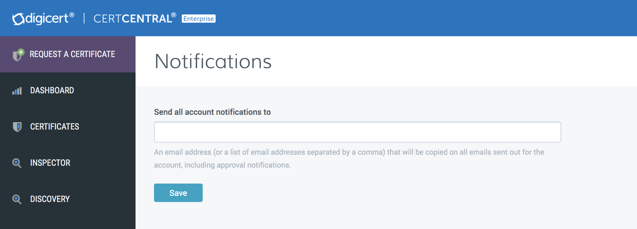
2.3.3.4.2 Set Up Email Notification Accounts
In the CertCentral account’s sidebar menu, click Settings > Notifications.
On the Notifications page in the Send all account notifications to box, add the email addresses that should be copied on all emails sent from the account.
Note: When setting up multiple notification accounts, use commas to separate the email addresses.
When finished, click Save.
2.3.3.4.3 Certificate Renewal Notifications
After DigiCert has issued the first certificate, configure the Certificate Renewal Settings (such as when renewal notifications are sent and to whom notifications are sent) to help prevent unexpected certificate expirations.
When configuring the certificate renewal settings, there are two options:
- Nonescalation Certificate RenewalsThis option sends renewal notifications to the same email addresses at every stage as certificates get closer to expiration or after they have expired.
- Escalation Certificate RenewalsThis option configures email escalation settings in which additional email addresses can receive renewal notifications at critical stages as certificates get closer to expiring or after they have expired. This allows additional oversight of certificate expiration.
2.3.3.4.4 Configure Nonescalation Renewal Notifications
Use the steps below to send all renewal notifications to the same email addresses at every stage as certificates get closer to expiring or after they have expired.
In the CertCentral account’s sidebar menu, click Settings > Preferences.
On the Division Preferences page, scroll down to the Certificate Renewal Settings, and uncheck Enable Escalation.
In the Send request renewal notifications to box, enter the email addresses for the people who should receive the renewal notifications (comma separated).
Under When certificates are scheduled to expire in, check the boxes to indicate when to send renewal notices.
Note: These options determine when email notifications are sent. For example, if only 30 days, 7 days, and 3 days are checked, no email notifications will be sent 90 days or 60 days before certificates expire.
In the Default Renewal Message box, type an optional renewal message for inclusion in all the renewal notification emails.
Click Save Settings when finished.
2.3.3.4.5 Configure Escalation Renewal Notifications
Email escalation settings allow control over what email addresses will receive renewal notifications at each stage as certificates approach or reach expiration.
In the CertCentral account’s sidebar menu, click Settings > Preferences.
On the Division Preferences page, scroll down to Certificate Renewal Settings, and check Enable Escalation.
Under Days before expiration, check the boxes for when renewal notices should be sent.
Under Additional email addresses or distribution lists, enter the email addresses for the people who should receive each renewal notification (comma separated).
In the Default Renewal Message box, type an optional renewal message for inclusion in all renewal notification emails.
Click Save Settings when finished.
2.3.3.5 Managing Custom Order Fields
CertCentral allows users to add custom fields to certificate order forms. Use the custom field metadata to search or sort a set of certificate orders that match the metadata search criteria.
Note: The Custom Fields feature is off by default. To enable this feature for a CertCentral account, please contact a DigiCert account representative.
Once enabled for a CertCentral account, the Custom Order Fields menu option is added to the sidebar menu under Settings (Settings > Custom Order Fields).
2.3.3.5.1 Custom order form field features
Apply to Future and Present Requests–When a custom order form field is added, the field is also added to pending requests. If the field is required, the pending requests cannot be approved until the field is completed.
Apply to Entire Account–When custom order form fields are added, the fields are applied to the order forms for the entire account. Custom order form fields cannot be set per division.
Apply to All Certificate Types–When custom order form fields are created, the fields are added to the order forms for all certificate types (SSL, Client, Code Signing, etc.). A custom order form field cannot be added to the order forms for only SSL certificate types.
Apply to Guest URLs–When custom order form fields are added, these fields are added to the certificates ordered from directly inside the CertCentral account as well as from any guest URLs that have been sent.
Different Types to Choose From–When custom order form fields are created, different types of fields can be added such as single-line and multiple-line text boxes and email address and email address list boxes.
Required or Optional–When custom order form fields are added, they can be required or optional. Required fields must be completed before the order can be approved. Optional fields can be left blank.
Deactivated or Activated–After a custom order form field has been added, the field can be deactivated (removed) and activated (added back) as needed. Deactivated fields are removed from pending requests but not from issued orders. Activated fields are added to pending requests. If the field is required, it must be completed before the request can be approved.
2.3.3.5.2 Add a Custom Field to Request Forms
In the CertCentral account in the sidebar menu, click Settings > Custom Order Fields.
On the Custom Order Form Fields page, click the Add Custom Order Form Field link.
In the Add Custom Order Form Field window, configure the custom field:
Label |
In the box, type a name/label for the field (e.g., Direct Report’s Email Address). |
Input Type |
In the drop-down list, select an input type for the field (i.e., email
address).
Input Types:
|
This field should be required for all new requests |
If the field needs to be completed before the request can be submitted (or approved for pending requests), check this box. Note: If this box is not checked, the field appears on the order form with the word “optional” in the box. The requester does not need to complete the box for the request to be submitted (or approved for pending requests). |
When finished, click Add Custom Form Field.
2.3.3.6 User Management
Add a user to the CertCentral account.
In the CertCentral account in the sidebar menu, click Account > Users.
On the Users page, click Add User.
On the Add User page in the User Details section, enter the new user’s information.
In the User Access section, assign the user a role, and configure their division access if applicable:
Username |
We recommend using the user’s email address. |
Restrict this user to specific divisions |
Check this box if the role should be restricted to specific divisions. Note: This option appears only if divisions within the CertCentral account are being used. |
User is restricted to the following divisions |
Select the divisions to which the role is restricted. Note: This drop-down appears only if “Restrict this user to specific divisions” is checked. |
Allow this user to log in only through SAML Single Sign-On SSO |
Check this box if this user should be restricted from being able to log in with username and password. Note: SAML SSO must be configured in the account and the IdP must be configured with this user’s information. |
Role |
Select a role for the new user: Administrator, Standard User, Finance Manager, or Manager. |
Limit to placing and managing their own orders |
To create a Limited User role, select Standard User, and check this box. |
When finished, click Add User.
What’s next
The newly added user will receive an email with instructions for setting up their account credentials and can use them to sign in to their CertCentral account.
2.3.3.7 Revalidation Processes
Organization and domain validation typically expire in two years. When the validation status nears expiration, CertCentral sends a notification and automatically initiates a revalidation process. The user should complete the steps outlined in Day 0 Organization Validation and Domain Validation. The standards governing the requirements surrounding (re)validation processes are encapsulated in the CA/Browser Forum’s Baseline Requirements (https://cabforum.org/baseline-requirements-documents/). The specific allowed methods of validation will change over time.
Note: This revalidation process is outside the Venafi certificate management processes.
OV validation and revalidation: two years
DV validation and revalidation: two years
EV validation and revalidation: one year
Note: Extended Validation provides additional levels of vetting surrounding the legal entity represented in a certificate. Vetting ensures that a complete picture of the identity, which has proven control over the domain in the certificate, is available to user agents verifying the certificate.
2.4 F5 BIG-IP Local Traffic Manager (LTM)
BIG-IP Virtual Edition (VE) is a version of the BIG-IP system that runs as a virtual machine in specifically supported hypervisors. BIG-IP VE emulates a hardware-based BIG-IP system running a VE-compatible version of BIG-IP software.
2.4.1 Day 0: Installation and Standard Configuration
2.4.1.1 Prerequisites
VMware ESX 6.5
2 virtual Central Processing Units (CPUs)
4 GB RAM
1 x VMXNET3 virtual network adapter or Flexible virtual network adapter (for management)
1 x virtual VMXNET3 virtual network adapter
1 x 100 GB Small Computer System Interface disk, by default
connection to a common NTP source
SMTP for BIG-IP to send email alerts
a computer with internet (browser) access to activate license
license key for F5 BIG-IP
F5 Support ID account
2.4.1.2 Download the Virtual Appliance
To deploy BIG-IP VE, download the open virtualization appliance (OVA) file to your local system.
Open the F5 Downloads page at https://downloads.f5.com.
Log in with an F5 Support ID.
In the Downloads Overview page, click Find a Download button.
In the Select a Product Line page, click the BIG-IP v13.x / Virtual Edition… link.
In the Select a Product Version… page, click the 13.1.1.4_Virtual-Edition link.
In the Software Terms… page, review, then click I Accept button to agree to terms and conditions.
In the Select a Download page, click the BIGIP-13.1.1.4-0.0.4.ALL-scsi.ova link.
In the Download Locations page, click the link nearest to the correct region.
Save the OVA file to the local computer.
2.4.1.3 Deploying the BIG-IP OVA
Use the Deploy Open Virtualization Format (OVF) Template wizard from within the VMware vSphere client. Follow the steps in this procedure to create an instance of the BIG-IP system that runs as a virtual machine on the host system.
Start the vSphere Client and log in.
Launch the Deploy OVF Template wizard.
Select an OVF template from Local file. Select the previously downloaded OVA file.
In the Virtual machine name field, type in
F5lb1.ext-nccoe.org.Then select the location for this virtual machine. Click Next.Select the compute resource and click Next.
Verify that the OVF template details are correct, then click Next.
Review the template details, then click Next.
Review License agreements. Select “I accept…” and click Next.
Read and accept the license agreement, and click Next.
Accept the default value 2 CPUs and click Next.
Accept the default value Thick Provision Lazy Zeroed and click Next.
Assign the networks to the network interface cards (NICs) and click Next.
NIC 1: VLAN 2199 (Datacenter Secure)
NIC 2: VLAN 2201
NIC 3: VLAN 2197 (DMZ)
Review information and click Finish.
2.4.1.4 Assigning a Management IP Address to a BIG-IP VE Virtual Machine
The BIG-IP VE virtual machine needs an IP address assigned to its virtual management port.
In the main vSphere client window, Power On the BIG-IP.
Launch a Console session for the BIG-IP.
At the login prompt, log in as
root / default.At the config # prompt, type
config.The Configure Utility panel appears.
Press Enter for OK.
The Configure IP Address panel appears.
For “Automatic configuration…”, choose No.
For IP Address, type
192.168.3.85Choose OK.For Netmask, type
255.255.255.0. Choose OK.For Management Route, choose Yes.
For Management Route, type
192.168.3.1Choose OK. The Confirm Configuration panel appears. (This Gateway address is used for management traffic.)Review the IP information, and choose Yes. Return to the config # prompt.
2.4.1.5 Log in to BIG-IP for the First Time
After the initial login to the BIG-IP, the Setup Utility will guide through the initial setup process.
Open the browser and navigate to the BIG-IP address https://192.168.3.85.
Log in as the default admin/admin.
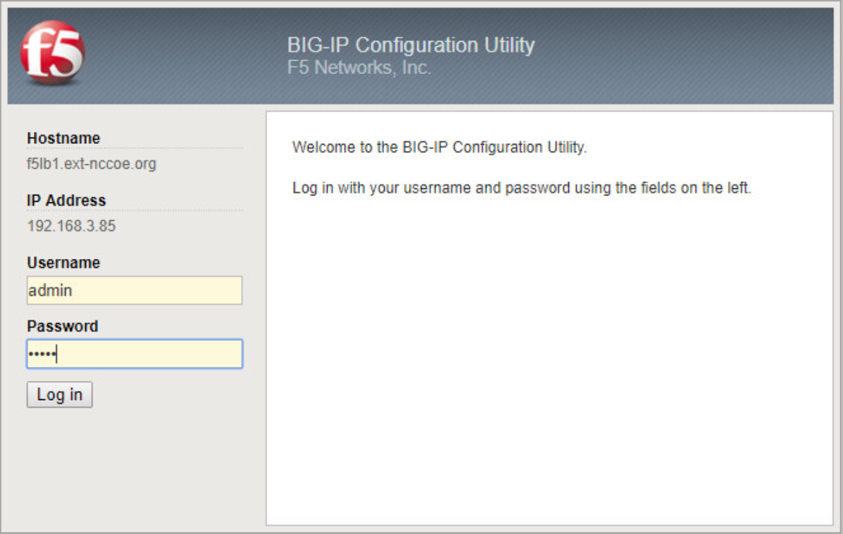
The Setup Utility panel appears, then click Next.
For License, click Activate.
As a prerequisite, the user should already have a BIG-IP VE license key. Copy the key and paste in the Base Registration Key field.
This step is dependent on internet access for the BIG-IP.
If the management route configured in the previous section has a path to internet, select Automatic. Click Next. Review the End User License Agreement (EULA) and click Agree. Then go to step 7.
Otherwise, select Manual. Click Next.
Left-click in the Dossier field, and select all the encrypted text with Ctrl-A. Copy the selected text with Ctrl-C.
Assuming the administration computer has internet access, click the “Click here to access F5…” link. A new browser tab appears.
In the Enter Your Dossier field, paste in the copied text. Click Next.
Review the EULA, and select “I have read and agree… .” Click Next.
Left-click the license text field, and select all text with Ctrl-A. Copy selected text with Ctrl-C.
Return to the BIG-IP Setup Utility. In the License field, paste in the copied text. Click Next.
Some BIG-IP services will restart and log the user off the BIG-IP. It will automatically resume. Click Continue.
Review the License page. Click Next.
On the Resource Provisioning page, verify that the only default value, Local Traffic (LTM), is selected and set to Nominal. Click Next.
On the Device Certificates page, leave the default as self-sign device Certificate. Click Next.
On the Platform page, fill these values. Then click Next.
Field |
Value |
Comments |
Management Port Configuration |
443 |
|
IP Address |
192.168.3.85 |
|
Network Mask |
255.255.255.0 |
|
Management Route |
192.168.3.1 |
|
Host Name |
f5lb1.ext-nccoe.org |
|
Time Zone |
EST |
|
Root Account |
<your password> |
Refer to NIST SP 800-63B for password guidance. |
Admin Account |
<your password> |
Refer to NIST SP 800-63B for password guidance. |
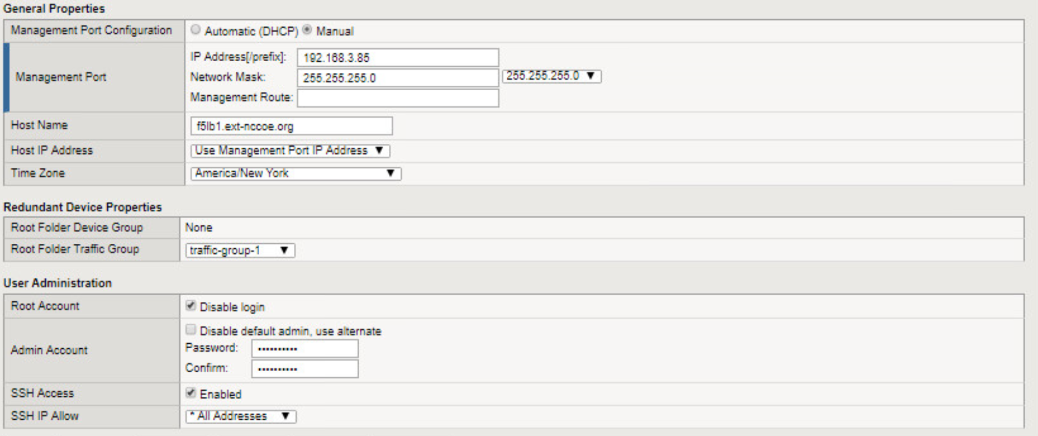
System logs off the user with password change. Log back in with the new admin password.
In the Standard Network Configuration page, click Next.
In the Redundant Device Wizard Options page, Un-Select Display configuration synchronization options.
In the Internal Network Configuration page, fill in these values.
Address |
192.168.4.85 |
Netmask |
255.255.255.0 |
VLAN Interfaces |
internal |
Tagging |
untagged |
Click Add, then click Next.
In the External Network Configuration page, fill in these values.
Address |
192.168.5.86 |
Netmask |
255.255.255.0 |
VLAN Interfaces |
external |
Tagging |
untagged |
Click Add, then click Finished.
2.4.1.6 BIG-IP Configuration Utility
There are at least two ways to administer the BIG-IP.
Use SSH to connect to the BIG-IP to access the command line interface, referred to as traffic management shell (TMSH).
With a web browser, navigate to the management URL—referred to as Configuration utility and mainly used in this guide.
Open browser and navigate to the BIG-IP address https://192.168.3.85.
Log in as admin, and use the password modified from the default during Setup wizard.
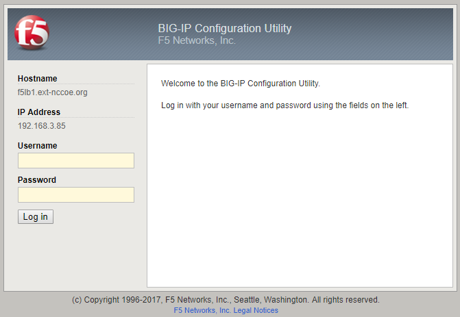
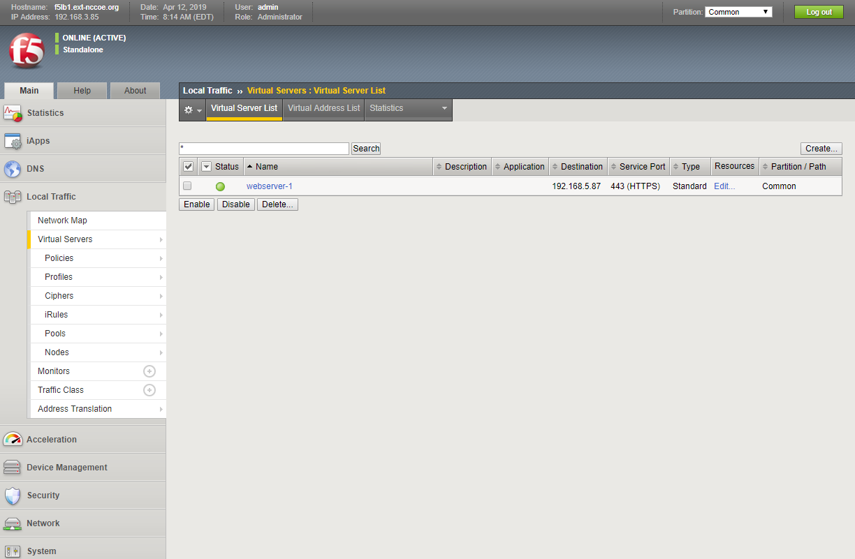
2.4.1.7 Configure NTP
Time synchronization is crucial when multiple BIG-IPs are in a cluster (not covered in this guide). It is also necessary for accuracy of logging information.
Log on to the Configuration utility.
Navigate to Main > System. Then click Configuration > Device > NTP.
The NTP panel appears.
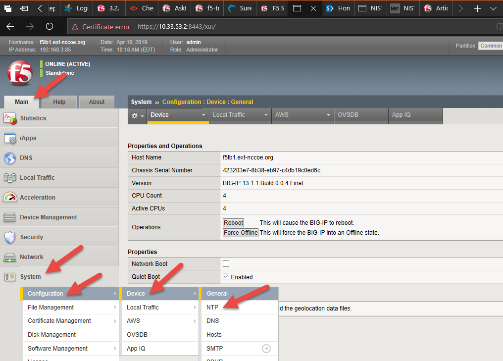
In the Address field, type
time-a-g.nist.gov.Click Add.In the Address field, type
time-b-g.nist.gov.Click Add.Click Update.
2.4.1.8 Configure SMTP
BIG-IP can be configured to send email alerts.
Navigate to Main > System. Then click Configuration > Device > SMTP.
The SMTP panel appears.
In the upper right corner, click the Create button.
The New SMTP Configuration panel appears.
Fill in these values.
Name |
mail1 |
SMTP Server Host Name |
mail1.int-nccoe.org |
Local Host Name |
f5lb1-ext-nccoe.org |
From Address |
f5-big-ip@nccoe.org |
Click Finish.
2.4.1.9 Configure Syslog
Log events either locally on the BIG-IP system or remotely by configuring a remote syslog server.
Log on to the Configuration utility.
Navigate to System > Logs > Configuration > Remote Logging.
In Remote IP field, type
192.168.3.12.Click Add.
Click Update.
2.4.1.10 Secure BIG-IP to NIST SP 800-53
This section provides guidance on using the F5 iApp for NIST SP 800-53 (Revision 5) to configure a BIG-IP device to support security controls according to NIST SP 800-53 (Revision 4): Security and Privacy Controls for Federal Information Systems and Organizations (updated January 2, 2015).
Some controls (policies plus supporting technical measures) that organizations adopt by complying with NIST SP 800-53 (Revision 5) relate to the BIG-IP configuration.
This practice guide discusses the security controls in Appendix F of NIST SP 800-53 (Revision 5) [D2] that apply to BIG-IP configuration and shows how to support them. It also focuses on configuring the management features of the BIG-IP system rather than the network-traffic-processing modules of a system such as BIG-IP Local Traffic Manager. This approach helps the user manage the BIG-IP system as an entity responsive to NIST SP 800-53 (Revision 5) controls. Using BIG-IP as a tool to help control other entities, such as network-based applications, is beyond the scope of this project.
2.4.1.10.1 F5 iApp
F5 iApp is a feature in the BIG-IP system that provides a way to simplify BIG-IP configurations. An iApp template brings together configuration elements, architectural rules, and a management view to deliver an application reliably and efficiently.
2.4.1.10.2 Download the iApp for NIST SP 800-53 (Revision 5) Compliance
In a browser, open the F5 Downloads page at https://downloads.f5.com.
Log in with an F5 Support ID.
In the Downloads Overview page, click Find a Download button.
In the Select a Product Line page, under Product Line column, click iApp Templates.
In the Select a Product Version… page, click iApp-Templates.
Review the EULA, then click I Accept.
In the Select a Download page, click iapps-1.0.0.546.0.zip.
In the Download Locations page, click on the link nearest to the user’s region.
Save the zip file to the local computer.
2.4.1.10.3 Import iApp to BIG-IP
Unzip the downloaded file.
Open browser and navigate to the BIG-IP address https://192.168.3.85.
Log in as admin/admin.
On the left menu, click Main > iApps > Templates. Then on the right side, click Import button.
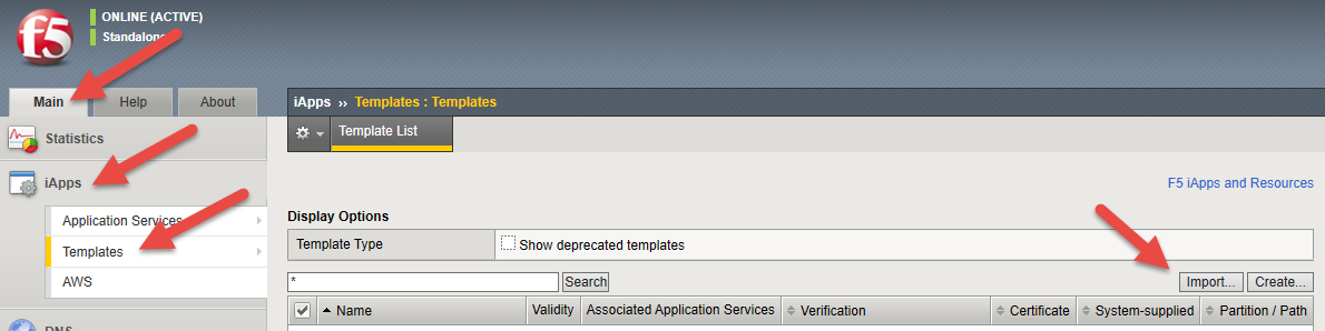
Browse to the file unzip location and to the subfolder \iapps‑1.0.0.546.0SecurityNISTRelease_Candidates.Select the file f5.nist_sp800-53.v1.0.1rc5.tmpl, then click Open.
Click Upload.
On page 2 of the Template List, verify that the f5.nist_sp800-53.v1.0.1rc5 template has been uploaded.
2.4.1.10.4 Deploy the NIST iApp
On the left menu, click Main > iApps > Application Services. Then on the right side, click Create button.
The Template Selection panel appears.
In the Name field, type
nist-800-53.In the Template pull-down, select f5.nist_sp800-53.v1.0.1rc5.
The New Application Service panel appears.
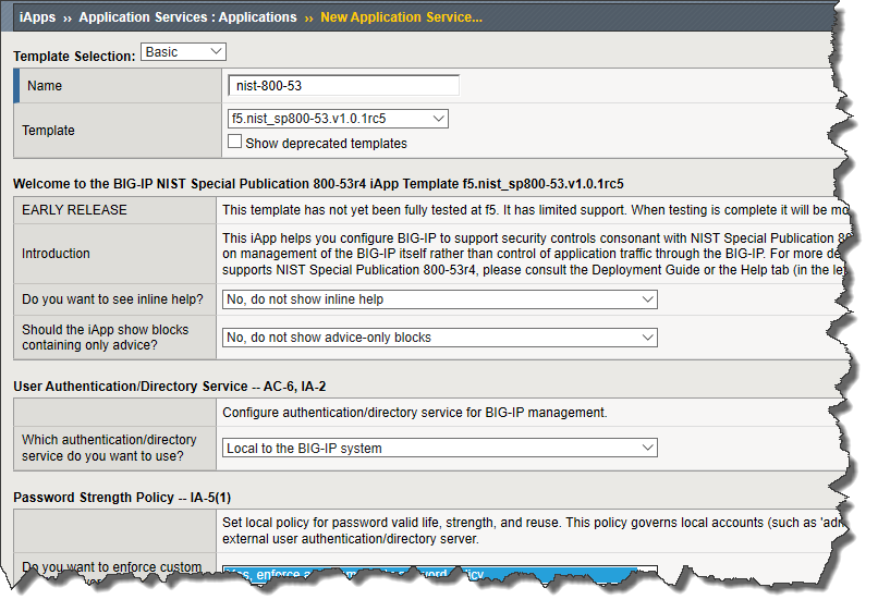
Fill in the iApps with parameters in the following table. Leave everything else as default values.
Password Strength Policy—IA-5(1) |
|
Do you want to enforce custom local password policy? |
“Yes, enforce a custom…” |
How many days should pass before the password expires? |
0 |
How many changes before reuse? |
0 |
How many characters should be the minimum for each setting? |
Length = 8 |
Maximum Failed Login Attempts—AC-7 |
|
Disable account after several failed login attempts? |
“Yes, limit fail…” |
Allow how many consecutive login failures before disabling the account? |
9 |
NTP Configuration—AU-8(1,2) |
|
What is the IP address or FQDN of the primary NTP server? |
time-a-g.nist.gov |
What is the IP address or FQDN of the first alternate NTP server? |
time-b-g.nist.gov |
Syslog Configuration—AU-8, AU-9(2), AU-12(2) |
|
Should log messages use International Standards Organization (ISO) date format? |
“Yes, log messages…” |
Do you want to add syslog servers? |
“Yes, use this iApp…” |
Which syslog servers do you want to add? |
Server: syslog2.int-nccoe.org |
Click Finished.
2.4.2 Day 1: Product Integration Configuration
2.4.2.1 Prerequisites
Venafi installed
web servers for load balance
2.4.2.2 Venafi Integration
For information on integration with Venafi TPP, see Section 2.6.13.1.
2.4.2.3 Load Balance Web Servers
2.4.2.3.1 Create a Pool to Manage https Traffic
A pool (a logical set of devices, such as web servers, that are grouped together to receive and process https traffic) can be created to efficiently distribute the load on the server resources.
On the Main tab, click Local Traffic > Pools.
The Pool List screen opens.
Click Create.
The New Pool screen opens.
In the Name field, type
app1_pool.For the Health Monitors setting, assign https by moving it from the Available list to the Active list.
Use the New Members setting to add each resource to include in the pool:
In the Address field, type
192.168.4.2.In the Service Port field type
443.Click Add.
Repeat step 5 for these three IP addresses.
192.168.4.3192.168.4.4192.168.4.7
Click Finished.
The https load balancing pool appears in the Pool List screen.
2.4.2.3.2 Create Client SSL Profile
Profile for BIG-IP to decrypt traffic from browser
On the Main tab, click Local Traffic > Profiles > SSL > Client.
The SSL Client List screen opens.
Click Create.
The New Client SSL Profile screen opens.
In the Name field, type
app1_client-ssl.In the Certificate Key Chain setting, select the checkbox on the right. Then click Add.
The Add SSL Certificate to Key Chain screen opens.
For Certificate pull-down, select app1.tls.nccoe.org-<value>.
For Key pull-down, select app1.tls.nccoe.org-<value>.
Click Add.
Click Finished.
2.4.2.3.3 Create Server SSL Profile
Profile for BIG-IP to encrypt traffic to web servers:
On the Main tab, click Local Traffic > Profiles > SSL > Server.
The SSL Server List screen opens.
Click Create.
The New Server SSL Profile screen opens.
In the Name field, type
app1_server-ssl.In the Certificate setting, select the checkbox on the right. Then select app1.tls.nccoe.org-<value> in the pull-down.
In the Key setting, select the checkbox on the right. Then select app1.tls.nccoe.org-<value> in the pull-down.
The Add SSL Certificate to Key Chain screen opens.
For Certificate pull-down, select app1.tls.nccoe.org-<value>.
For Key pull-down, select app1.tls.nccoe.org-<value>.
Click Finished.
2.4.2.3.4 Create a Virtual Server to Manage https Traffic
A virtual server can be specified to be either a host virtual server or a network virtual server to manage https traffic.
On the Main tab, click Local Traffic > Virtual Servers.
The Virtual Server List screen opens.
Click the Create button.
The New Virtual Server screen opens.
In the Name field, type
app1_vs.In the Destination Address field, type
192.168.5.85.In the Service Port field, type
443.In the HTTP Profile setting, select http in the pull-down.
In the SSL Profile (Client) setting, from the Available list, select app1_client-ssl, and click the
 button to move over
to the Selected list.
button to move over
to the Selected list.In the SSL Profile (Server) setting, from the Available list, select app1_server-ssl, and click the
button to move over
to the Selected list.In the Source Address Translation setting, select Auto Map in the pull-down.
In the Default Pool setting, select app1_pool in the pull-down.
In the Default Persistence Profile setting, select cookie in the pull-down.
Click Finished.
The https virtual server appears in the Virtual Server List screen.
2.4.2.3.5 Create Redirect Virtual Server from http to https
When a user types http://<virtual server> in the browser, this virtual server redirects the user to the secure site https://<virtual server>.
On the Main tab, click Local Traffic > Virtual Servers.
The Virtual Server List screen opens.
Click the Create button.
The New Virtual Server screen opens.
In the Name field, type
app1_redir_vs.In the Destination Address field, type
192.168.5.85.In the Service Port field, type
80.In the HTTP Profile setting, select http in the pull-down.
In the iRules setting, select _sys_https_redirect in Available, and click the
button to move over to the Enabled list.Click Finished.
The http redirect virtual server appears in the Virtual Server List screen.
2.4.3 Day N: Ongoing Security Management and Maintenance
2.4.3.1 Software Updates
BIG-IP VE updates in the same major version are installed in a similar manner as updates to BIG-IP software already installed on BIG-IP hardware. There is no need to reinstall BIG-IP VE in the hypervisor guest environment to upgrade the system. To update a BIG-IP VE virtual machine, use the Software Management tool in the Configuration utility, or upgrade the software from the command line. The update procedure described in this guide uses the Software Management tool.
2.4.3.1.1 Download the Latest Software
Software release notes contain instructions for that specific installation.
To find the latest software version for an F5 product:
Navigate to F5 Downloads (downloads.f5.com).
Click Find a Download.
Find the product desired for download, and click the link for the appropriate version.
Find and click the link for the update to download.
Read and accept the End User Software license agreement.
Click the file name, choose a download location, and save the file to the computer.
2.4.3.1.2 Upgrading BIG-IP Software
Before upgrading the BIG-IP software, we recommend reviewing the release notes on AskF5 (support.f5.com) in the Documentation section of the product and version. In particular, verify the new version supports the hardware, and carefully review these items:
known issues list
behavior change section(s)
upgrading from earlier versions section
upgrading from earlier configurations section
installation checklist
2.4.3.1.3 Import a BIG-IP VE Software Update
To install an update, BIG-IP software needs access to the ISO file previously downloaded.
Open browser, and navigate to the BIG-IP address https://192.168.3.85
Log in as an admin.
On the Main tab, click System > Software Management.
The Software Management Image List screen opens.
At the right side of the screen, click Import.
The New Image screen opens.
Click Browse to navigate to the downloaded installation file.
When the image name appears in the Software Image field, click Import to begin the operation.
The system presents a progress indicator during the operation.
2.4.3.1.4 Installing a BIG-IP VE update
After import the software image, initiate the installation operation.
On the Main tab of the navigation pane, click System > Software Management.
The Software Management Image List screen opens.
From the Available Images table, select the software image you want to install.
The image properties screen opens.
Click Install.
The Install Software screen opens.
Select the disk you want to install the image on, and type or select a volume name, and click Install.
The upgrade process installs the software on the inactive disk location that you specify. This process usually takes between three and ten minutes.
Tip: If a problem arises during installation, use log messages to troubleshoot a solution. The system stores the installation log file as /var/log/liveinstall.log.
The software image is installed.
2.4.3.1.5 Reboot BIG-IP VE to update
When the installation operation is complete, you can safely reboot into the newly installed volume or partition.
On the Main tab of the navigation pane, click System > Software Management.
The Software Management Image List screen opens.
On the menu bar, click Boot Locations.
The Boot Locations screen opens.
In the Boot Location column, click the link representing the boot location you want to activate.
The properties screen for the boot location opens.
Click Activate.
A confirmation screen opens.
Click OK to initiate the reboot operation.
The system presents progress messages during the restart operation.
When the BIG-IP VE system reboot is complete, the system presents the login screen. To configure the system, log in using an account that has administrative permissions.
2.4.3.2 License and Entitlement
If support is purchased from F5, it is associated with a particular BIG-IP system. A system with an active support contract is considered entitled until the contract expires. To continue receiving support, the contact must be renewed.
Licenses are also associated with modules purchased to run a specific system. Model licenses are considered add-ons to the main license for a system, and are automatically linked to the main BIG-IP system license and eligible for technical support if that system is entitled.
Major software upgrades are only supported for entitled systems and require relicensing of the BIG-IP system. Minor upgrades do not require relicensing.
2.4.3.2.1 Viewing and verifying a BIG-IP system license
Test the validity of the BIG-IP software license by obtaining license information in any of the following ways:
view license information at the command line
request a product license profile from F5
view license profile in BIG-IP iHealth®
view license profile in the Configuration utility
At the command line, type the following command:
tmsh show /sys license
Output displays licensing information for the BIG-IP system should include a list of active modules. For a system with a valid license, output appears similar to the following example:
2.4.3.2.2 Provisioning licenses
If a license is installed for an add-on module on a BIG-IP system, you must provision resources for the module.
Until provisioned, module function is limited in the following ways:
the system does not perform the functions of the licensed module
items related to the module do not appear in Configuration utility menus
the TMOS Shell (tmsh) does not present or permit configuration of objects related to the module.
the bigstart status command returns output similar to the following example for daemons related to the unprovisioned module: <daemon_name> down, Not provisioned For information on provisioning modules, refer to “Modules.”
When you upgrade a BIG-IP system, the install script verifies the Service Check Date with the license check date of the version being installed. If the service check date is missing or the verification process finds your license pre-dates the software’s release date, a line displays in the /var/log/liveinstall.log with a note about the service check date verification, and the installation of the software may continue.
2.4.3.2.3 Reactivating a BIG-IP System License
F5 recommends reactivating the BIG-IP system license before conducting a software upgrade.
Follow these steps to reactivate a BIG-IP system license using the Configuration utility:
Navigate to System > License.
Click Re-activate.
In the Activation Method area, select Automatic (requires outbound connectivity).
Click Next.
2.4.3.2.4 Moving a BIG-IP VE license
BIG-IP VE licenses are permanently associated with the virtual instance. To move a license, contact F5 Technical Support for assistance. However, with BIG-IP 12.1.3.3 and BIG-IP 13.1 and later, you can move the RegKey without contacting support by revoking the instance’s license from tmsh, the Configuration utility, and iControl/REST by using the ‘tmsh revoke sys license’ command on that virtual instance. This action revokes the license and unlocks the RegKey—enabling the user to activate a new virtual machine.
Call F5 Technical Support for assistance if the connection is lost and you want to move the license to the current VE, if hypervisor crashes, or if you can’t access the password or network address.
2.4.3.3 Backup and Data Recovery
BIG-IP software offers two supported methods for backing up and restoring the configuration: user configuration set (UCS) archives and single configuration files. This guide focuses on using the UCS archive only. To create, delete, upload, or download an archive, you must have either administrator or resource administrator role privileges.
2.4.3.3.1 Backup Configuration Data to a UCS Archive
A UCS archive contains BIG-IP configuration data that can fully restore a BIG-IP system in the event of a failure or return material authorization.
Each time you back up the configuration data, the BIG-IP system creates a new UCS archive file in the /var/local/ucs directory. In addition to configuration data, each UCS file contains various configuration files necessary for the BIG-IP system to operate correctly.
A UCS archive contains the following types of BIG-IP system configuration data:
system-specific configuration files (traffic management elements, system and network definitions, and others)
product licenses
user accounts and password information
DNS
zone files
installed SSL keys and certificates
To easily identify the file, include the BIG-IP host name and current time stamp as part of the file name.
F5 recommends keeping a backup copy of the UCS archives on a secure remote server. To restore the BIG-IP system if you can’t access the /var /loca/ucs directory on the BIG-IP system, upload the backup file from the remote server, and use it to restore your system.
2.4.3.3.2 To create a UCS archive using the Configuration utility
When creating a new archive, unless otherwise directed, the BIG-IP system automatically stores it in /var/local/ucs directory—a default location. You can create as many archives as you want, but each archive must have a unique file name.
All boot locations on a BIG-IP system use the same /shared directory, making it a good choice for a UCS save location. Saving an archive to the /shared directory allows you to boot to another boot location and access the archive, and can greatly simplify the recovery from a variety of issues.
Navigate to System > Archives.
Click Create.
Type a unique file name.
To encrypt the archive for Encryption, click Enabled.
To include private keys in the BIG-IP system, for Private Keys, click Include. If you choose to include private keys, store the archive file in a secure environment.
Click Finished.
Click OK after the data is backed up and the file is created.
2.4.3.3.3 To download and copy an archive to another system using the Configuration utility
Navigate to System > Archives.
Click the UCS file name you want to download.
In Archive File, click Download <filename>.ucs.
Save the file.
Find the file in your computer’s Downloads folder and copy it.
2.4.3.3.4 Restoring Configuration Data from a UCS Archive
If the BIG-IP System configuration data becomes corrupted, you can restore the data from the archive currently stored in the directory /var/local/ucs.
When restoring configuration data, F5 recommends running the same version of the BIG-IP software on the BIG-IP system from which it was backed up.
F5 also recommends restoring a UCS file to another platform of the same model where the UCS file was created. Certain core hardware changes can cause a UCS to load properly on dissimilar hardware, requiring manual intervention to correct.
2.4.3.3.5 To restore a configuration in a UCS archive using the Configuration utility
Navigate to System > Archives.
Click the name of the UCS archive you want to restore.
To initiate the UCS archive restore process, click Restore.
When the restoration process is completed, examine the status page for any reported errors before proceeding to the next step.
To return to the Archive List page, click OK.
If you receive activation errors after restoring a UCS archive on a different device, you must reactivate the BIG-IP system license. Restarting the system ensures that the configuration is fully loaded after relicensing,
2.4.3.3.6 Downloading a UCS Archive to a Remote System
Downloading a copy of an existing archive to a remote system protects the configuration data should you need to restore your BIG-IP system and be unable to access the /var/local/ucs directory on the BIG-IP system.
To download an existing archive, first display the properties of the archive to specify the complete path name of the location where you want to save the archive copy.
Navigate to System > Archives.
Click the name of the archive that you want to view.
The General Properties for that archive display.
Click Download: <ucs filename>.
Click Save.
The BIG-IP system downloads a copy of the UCS file to the system from which you initiated the download.
2.4.3.3.7 Uploading a UCS Archive from a Remote System
If a UCS archive on your BIG-IP system is unavailable or corrupted, upload a previously created archive copy from a remote or backup system to replace it.
Navigate to System > Archives.
Click Upload.
Type the complete path and file name of the archive that you want to upload onto the BIG-IP system.
If you do not know the path or file name, click Browse and navigate to the location.
Click Upload.
The specified archive uploads to the /var/local/ucs directory on the BIG-IP system.
2.4.3.3.8 Deleting a UCS Archive
Use the Configuration utility to delete any archive on the BIG-IP system that is stored in the directory /var/ local/ucs.
Navigate to System > Archives.
Select the check box next to the name of the file you want to delete.
Click Delete.
Click Delete again.
The archive is deleted from the /var/local/ucs directory on the BIG-IP system.
2.4.3.4 Log Files and Alerts
This section provides context for our recommended procedures in the form of overviews and supplemental information, including the following topics:
Config for Syslog
Set up SMTP for email alerts
2.4.3.4.1 Managing Log files on a BIG-IP System
Log files track usage or troubleshoot issues—if left unmanaged, they can grow to an unwieldy size. The BIG-IP system uses a utility called logrotate to manage local log files. The logrotate script deletes log files older than the number of days specified by the Logrotate.LogAge database variable. By default, the variable is set to eight. Therefore, the system is configured to delete archive copies that are older than eight days.
To modify the Logrotate.LogAge database variable:
Log in to tmsh at the command line by typing the following command:
tmshModify the age at which log files are eligible for deletion by using the following command syntax:
modify /sys db logrotate.logage value <value 0 - 100>Save the change by typing the following command:
save /sys config
2.4.3.4.2 Audit Logging
Audit logging is an optional way to log messages pertaining to configuration changes that users or services make to the BIG-IP system configuration. Audit logging is also known as master control program.
LOG FILES AND ALERTS—PROCEDURES
(MCP) Audit Logging. As an option, you set up audit logging for any tmsh commands that users type on the command line.
For MCP and tmsh audit logging, select a log level. The log levels will not affect the severity of the log messages but may affect the initiator of the audit event.
2.4.3.5 Technical Support
In addition to Support Centers around the world, there are many technical resources available to customers.
2.4.3.5.1 Phone Support
Open a Case at any of the Network Support Centers:
1-888-882-7535 or (206) 272-6500
International contact numbers: http://www.f5.com/training-support/customer-support/contact/
2.4.3.5.2 AskF5 - Web Support
F5 self-support portal: http://www.askf5.com
2.4.3.5.3 DevCentral - F5 User Community
More than 360,000 members—including F5 engineering resources—are actively contributing, sharing and assisting our peers.
2.4.3.5.4 BIG-IP iHealth
BIG-IP iHealth comprises BIG-IP iHealth Diagnostics and BIG-IP iHealth Viewer. BIG-IP iHealth Diagnostics identifies common configuration problems and known software issues. It also provides solutions and links to more information. With BIG-IP iHealth Viewer, you can see the status of your system at-a-glance, drill down for details, and view your network configuration.
2.4.3.5.5 Subscribing to TechNews
AskF5 Publications Preference Center provides email publications to help keep administrators up-to-date on various F5 updates and other offerings:
TechNews Weekly eNewsletter Up-to-date information about product and hotfix releases, new and updated articles, and new feature notices.
TechNews Notifications Do you want to get release information, but not a weekly eNewsletter? Sign up to get an HTML notification email any time F5 releases a product or hotfix.
Security Alerts Receive timely security updates and ASM attack signature updates from F5.
To subscribe to these updates:
Go to the Communications Preference Center (https://interact.f5.com/F5-Preference-Center.html).
Under My preferences click Show.
Select the updates you want to receive.
Click Submit.
2.4.3.5.6 AskF5 recent additions and updates
You can subscribe to F5 RSS feeds to stay informed about new documents pertaining to your installed products or products of interest. The Recent additions and updates page on AskF5 provides an overview of all the documents recently added to AskF5.
New and updated articles are published over RSS. You can configure feeds that pertain to specific products, product versions, and/or document sets. You can also aggregate multiple feeds into your RSS reader to display one unified list of all selected document.
2.5 Symantec SSL Visibility Appliance
The Symantec SSL Visibility appliance is a high-performance transparent proxy for SSL network communications. It enables a variety of applications to access the plaintext (that is, the original unencrypted data) in SSL encrypted connections, and is designed for security and network appliance manufacturers, enterprise IT organizations, and system integrators. Without compromising any aspect of enterprise policies or government compliance, the SSL Visibility appliance permits network appliances to deploy with highly granular flow analysis while maintaining line rate performance.
2.5.1 Day-0: Install and Standard Configuration
2.5.1.1 Prerequisites
120V or 220V Power Source
computer with browser access to activate license and configure appliance
putty or a terminal emulator
four-post equipment rack with a depth of 27.75” to 37.00” with square mounting holes
category 5E network cables or better (Category 6 or 6A)
license key for SSL Visibility appliance
Broadcom account
DNS Server
SSL VISIBILITY running version 3.X
2.5.1.2 Unpacking the Appliance
Before racking and configuring the SSL Visibility Appliance, ensure the following contents are included in the SSL Visibility shipping package:

2.5.1.3 Rack-Mount the Appliance
The list below shows the requirements to install the SSL Visibility Appliance.
At least 1U rack space (deep enough for a 27” device)–power and management ports at rear
Phillips (cross head) screwdriver
Weight Capacity: 28 lb (12.7 kg)
Dimensions: 17.5” (W) x 19.5” (D) x 1.75” (H) (444.5 mm x495.3 mm x 44.5 mm)
Two available power outlets (110 VAC or 220-240 VAC)
Two IEC-320 power cords (normal server/PC power cords) should the supplied power cords not be suitable for your environment
Cooling for an appliance with two 450W power supply units
To see detailed instructions for installing the SSL Visibility in a rack, please refer to Symantec’s Quick Start guide located at the below link:
2.5.1.4 Connect Cables
To connect the appliance’s cables:
Connect a network cable between the Management Ethernet 1 port, on the rear of the SSL VISIBILITY appliance, and Datacenter Secure network.
Warning: When deploying the SV1800, SV2800, and SV3800 appliances, do not connect to the Management Ethernet 2 port. This port is not functional.
Connect the two AC power cords to the appliance’s AC power inlets on the rear panel. Two power supplies are provided for redundant operation.
Connect the other ends of the power cords to a 120 V or 220 V power source.
2.5.1.5 Power on the Appliance and Verify LEDs
Confirm the appliance’s power cord or power cords are securely connected to a 120 V or 220 V power source.
Power on the appliance by pressing its front-panel power button.
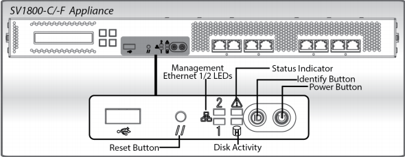
As the appliance boots verify the following:
The LCD displays startup messages while the appliance boots (Appliance Startup, Validating Firmware, Appliance Boot, etc.).
The System Status indicator for the SV1800 changes from red to off.
The LEDs for the Management Ethernet port (connected to a management workstation) light up.
When the boot process is complete, the LCD displays the appliance’s model, software version, and the Up/Down arrows.
2.5.1.6 Initial Appliance Configuration
To perform initial configuration of the SSL Visibility Appliance, connect a serial cable to the DB9 Serial port on the rear of the Appliance.
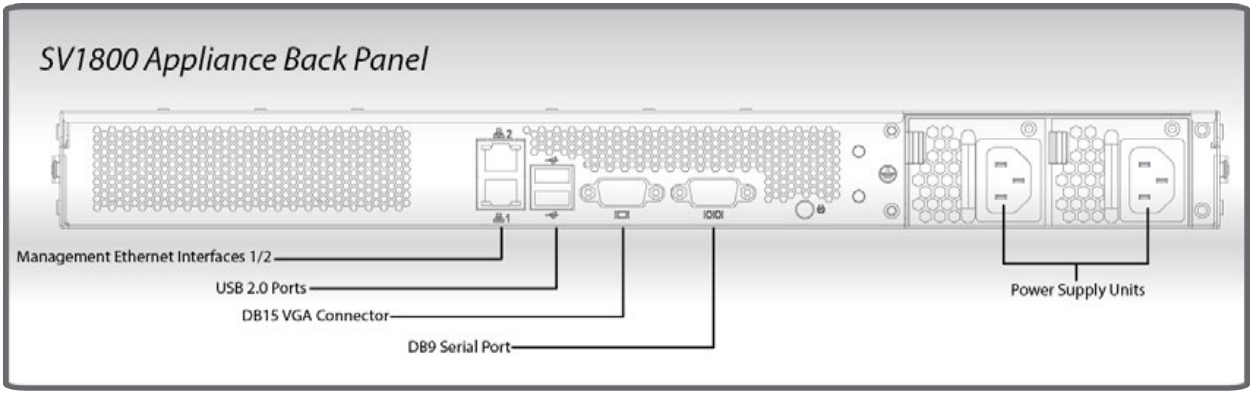
On the management laptop, open up the Putty Application and select a Connection type of Serial with a Speed of 115200.
Navigate to the Serial Category on the bottom left side of the window.
Configure the serial connection to support the SSL Visibility Appliance’s console speeds by selecting the following options:
Speed (baud): 115200
Data bits: 8
Stop bits: 1
Parity: None
Flow Control: None
Login into the appliance by using the default credentials of:
Username: bootstrap
Password: bootstrap
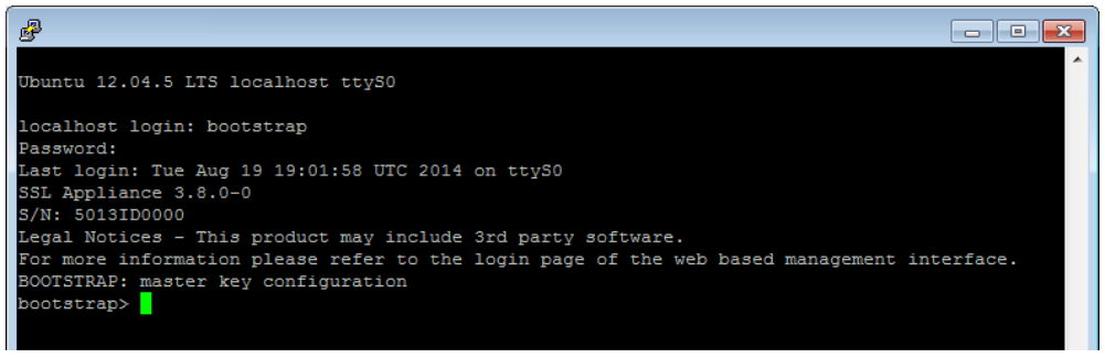
Next, create the master key by running the command:
master key create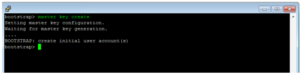
Create a new user by running the command:
user add admin manage-pki manage-appliance manage-policy audit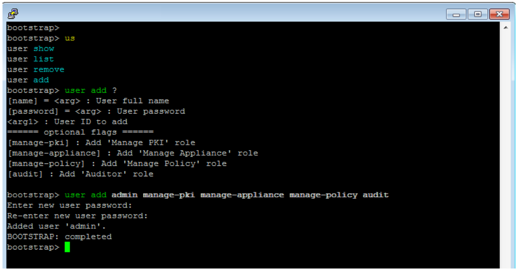
Tip: This step created a single admin user account with all four roles allocated to it. The only requirements for completing the bootstrap phase are that there is a user account with the Manage Appliance role and a user account with the Manage PKI role. These may be the same or different accounts. In most cases, creating a single account with all four roles is the simplest approach.
Run the following command to configure the management network interface with a static IP address:
network set ip 192.168.1.95 netmask 255.255.255.0 gateway 192.68.1.1Reboot the system for the changes to take effect (confirm that you wish to reboot) with the following command:
platform reboot
On reboot, confirm that the “SSL Visibility startup stage 3: CONFIRMED” is displayed as shown below.
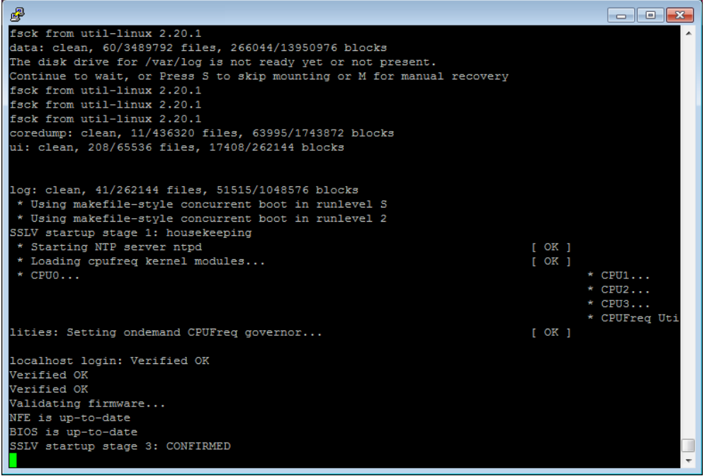
Confirm you can log in to the appliance via your browser. Log in via a web browser, using the format https://192.168.1.95. Log in with the username and password you created.
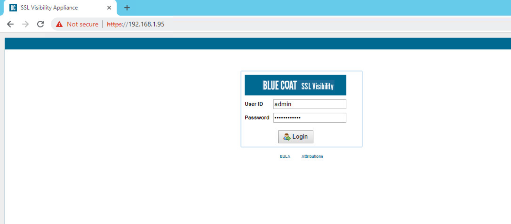
2.5.1.7 Date and Time (NTP)
To configure Date and Time, login into the WebUI by browsing to https://192.168.1.95.
Navigate to localhost > Date/Time.
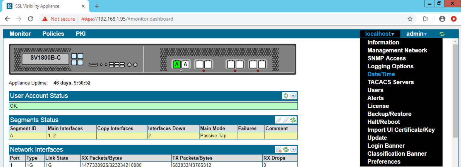
Click on the Add button
 under NTP Servers.
In the server field type time.nist.gov and click OK.
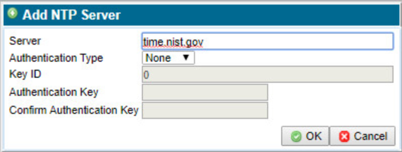
Click Apply Changes to save the new NTP server.
2.5.1.8 Additional Configuration
To add a host name and DNS for the SSL Visibility Appliance, perform the following steps:
Log in to the SSL Visibility by opening a web browser and navigating to https://192.168.1.95.
From the Dashboard page navigate to localhost > Management Network.
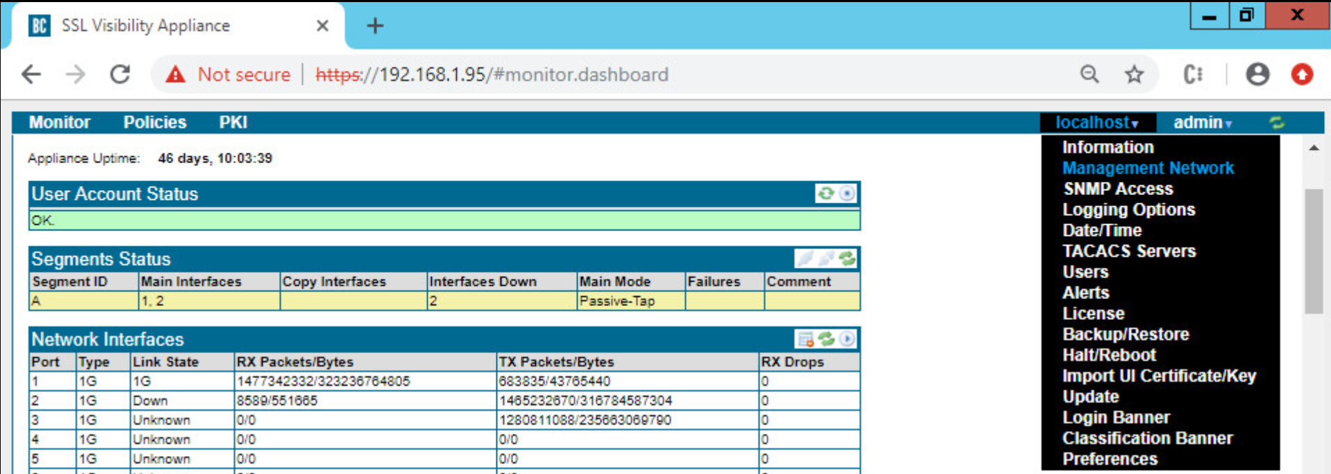
Click the Edit button
 under the Management Network Field.
Enter the following information into the fields:
MTU: 1500
Host Name: SSL Visibility.int-nccoe.org
Primary Nameserver: 192.168.1.6
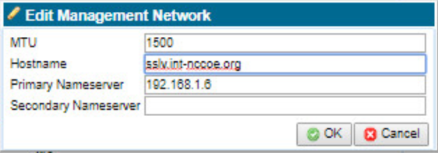
Click Apply Changes.
Click Reboot to restart the system and apply changes (required).
2.5.1.9 Broadcom Account Creation
To create a Broadcom Account, navigate to the following link:
https://portal.broadcom.com/web/guest/registration?source=CA
Enter the requested information and click Next.
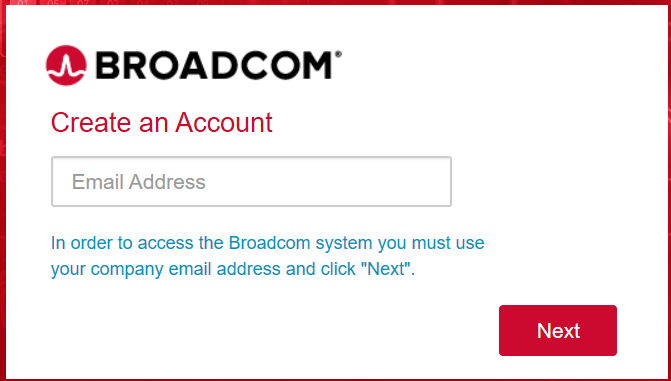
2.5.1.10 License the SSL Visibility Appliance
2.5.1.10.1 Download a Blue Coat License
Using your BlueTouch Online account, log in to the Blue Coat Licensing Portal.
(https://services.bluecoat.com/eservice_enu/licensing/register.cgi).
From the menu on the left side, select SSL Visibility, then select License Download.
When prompted, enter the serial number of your appliance, then press Submit.
Once the license is generated, press Download License File for the required SSL Visibility Appliance.
2.5.1.10.2 Install a Blue Coat License
Select SSL Visibility.int-nccoe.org > License.

Click the Add button
in the License field.On the Upload File tab, use the Choose File button to browse to the license file location.
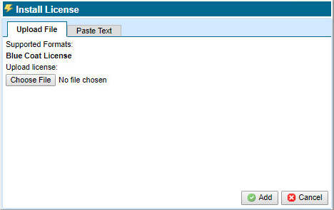
Click Add. You will see a confirmation message and the specific appliance platform model. The license is now installed, and all standard SSL Visibility Appliance features are operational.
2.5.2 Day 1: Product Integration Configuration
2.5.2.1 Prerequisites
Install version 3.x on the SSL Visibility Appliance.
Complete initial configuration as outlined in the Day 0 Section 2.5.1 above.
Required Ports, Protocols and Services:
SSL Visibility 3.x uses the following ports while operating—allow these ports when setting up SSL Visibility:
Inbound Connection to SSL Visibility Appliance
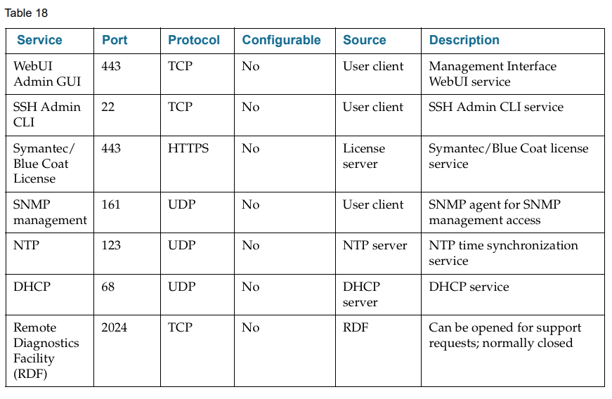
Outbound Connections from SSL Visibility Appliance
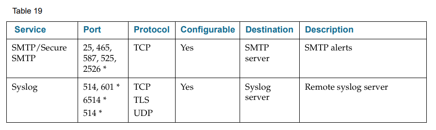
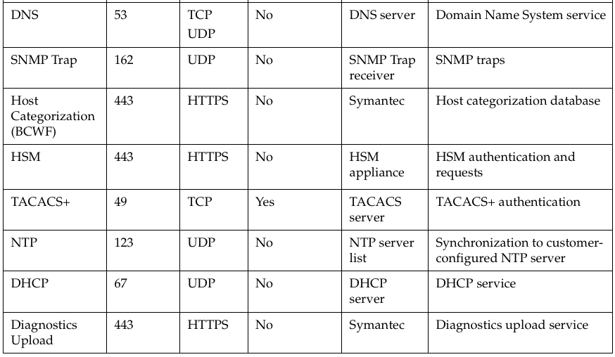
*Common Values For this Port
Required URLs
Ensure connectivity from SSL Visibility to the following URLs:
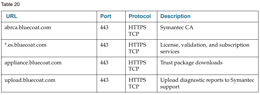
2.5.2.2 Venafi Integration
Venafi TPP was used to copy known server key and certificates to the SSL Visibility appliance for TLS decryption.
For information on integration with Venafi TPP, see Section 2.6.13.9.
2.5.2.3 Ruleset Creation
To ensure your SSL Visibility Appliance is connected and configured properly, create a basic ruleset to test that traffic isn’t getting blocked. To perform this test, create a ruleset with a Catch All Action of Cut Through.
Note: At least one rule must be added to the ruleset for SSL Visibility Appliance to start processing SSL traffic.
Select Policies > Rulesets.
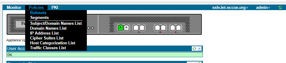
In the Rulesets panel, click the Add
 icon.
icon.In the Add Ruleset window, enter a name for the ruleset and click OK.
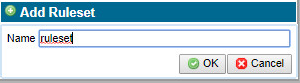
In the Ruleset Options panel, click the Edit
 icon.
icon. 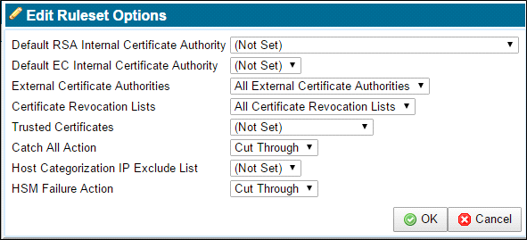
Confirm the Catch All Action is Cut Through.
Apply the Policy Changes.
2.5.2.4 Segment Creation
Note: Before creating the segment, determine your deployment mode and create a ruleset for the segment.
The following pictures demonstrate various passive tap deployment types:
(i).  (ii).
(ii). 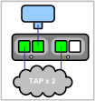 (iii).
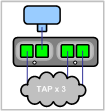
For purpose of this document we used (i).
Note: The latter two tap modes combine traffic from two or three network taps onto a single SSL Visibility Appliance segment. These ports are called aggregation ports.
2.5.2.4.1 Add a Segment
Select Policies > Segments.
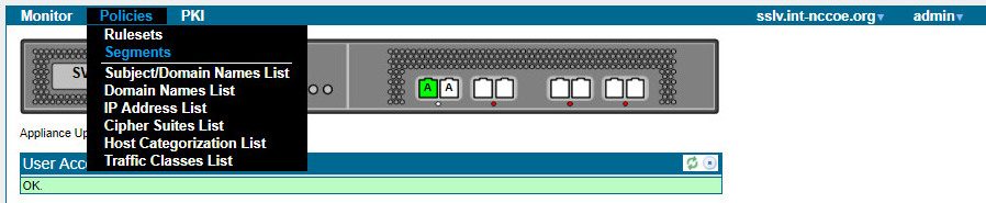
Click the Add
icon in the Segments field.Click Edit to select the Mode of Operation.
For Mode of Operation, choose
Passive
Tap mode.Click OK.
Select the Ruleset you previously created.
Choose the desired Session Log Mode.
Enter a brief description of the segment in the Comments box.
Click OK. The new segment appears in the Segments panel.
Apply the Policy Changes.
2.5.2.4.2 Activate a Segment
Select Policies > Segments.
In the Segments panel, select the segment to activate.
Click the Activate
 icon. The Segment Activation window displays.
Note: During segment activation, a series of screens appear that allow you to select the ports the segment will use, and any copy ports and modes where the copy ports will operate. Connect any copy ports to your passive security devices (for example, Symantec DLP Network Monitor, Security Analytics, or an IDS).
Follow the prompts. Once the segment is active, the system dashboard displays a green background for the segment, and there are entries under Main Interfaces and Copy Interfaces (if applicable to your deployment).
Apply the Policy Changes.
2.5.2.5 Verification
This section walks through verifying that the SSL Visibility is seeing SSL traffic without blocking it (cut through).
To see a list of recent SSL sessions, select Monitor > SSL Session Log.
Look for the domains of the servers that were accessed, and observe the value in the Action column. Since the initial rule you created cuts through all traffic, the Action should say Cut Through for all sessions.

2.5.2.5.1 Create a Rule to Test Decryption
To test the SSL Visibility Appliance is decrypting SSL traffic, add a rule that decrypts everything from a specific source IP (e.g., your laptop).
Note: At least one rule must be added to the ruleset for SSL Visibility Appliance to start processing SSL traffic.
Select Policies > Rulesets.
In the Rulesets panel, select the ruleset that was previously created.
In the Rules panel, click the Insert
icon to add a new rule. The Insert Rule dialog displays.For Action, select Decrypt (Certificate and Key Known).
Select one of the following:
If you imported one certificate, select Known Certificate with Key, and choose the certificate you imported.
If you imported multiple certificates, select Known Certificates with Keys and All Known Certificates with Keys.
For Source IP, enter the IP address of your computer.
Click OK.
Apply the Policy Changes.
Next Step: Use the SSL Session Log to verify that the SSL Visibility Appliance is decrypting properly.
2.5.2.5.2 Verify Decryption
View the SSL Session log to test, and verify the SSL Visibility Appliance is decrypting traffic according to the rules you created.
Access a variety of websites or internal SSL servers. If you have created policies for specific host categories, domains, IP addresses, etc., visit websites that test these policies.
To see a list of recent SSL sessions, select Monitor > SSL Session Log.
Look for the domains of the websites/servers you visited, and observe the value in the Action column. Is the value you expected listed? For example, if you wanted the SSL Visibility Appliance not to decrypt a particular type of traffic, does the Action say Cut Through? For sessions designated as decrypted, does the Action say Decrypt? If unexpected values appear, review your policies.
Note: When a session is decrypted, the Action column will show either Resign Certificate (if the deployment is using the certificate resigning method) or Certificate and Key Known (if you have imported known certificates and keys).
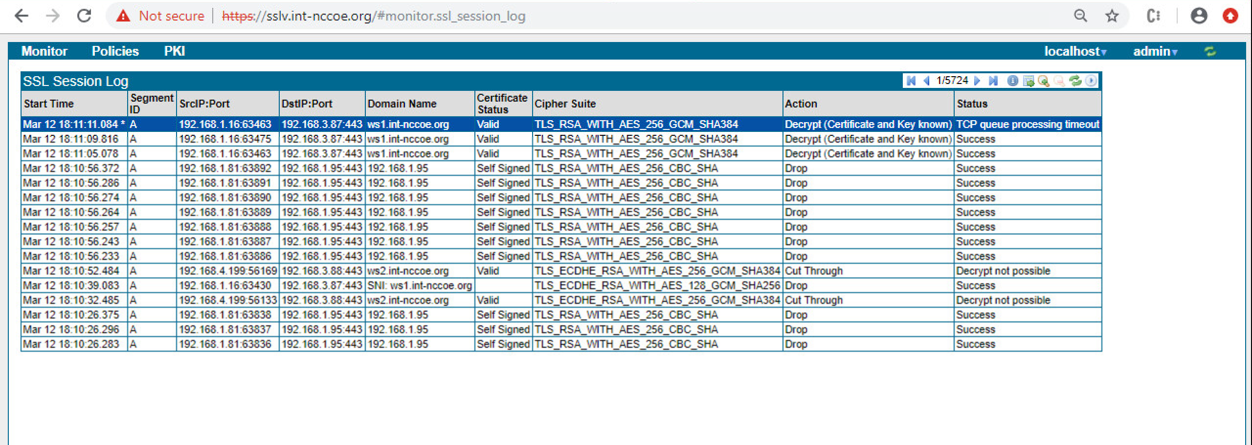
2.5.2.5.3 Other Ways to Learn About this Deployment Method
Download a PDF (https://www.broadcom.com/site-search?q=Visibility+SSL+First+Steps)
View a video tutorial (https://www.youtube.com/watch?v=qxSDDXhE_B8&feature=youtu.be)
2.5.3 Day N: Ongoing Security Management and Maintenance
2.5.3.1 Alerting & Monitoring
2.5.3.1.1 Alerts
Use the Alerts panels to configure the email details the system will use to send out alerts, monitor events, and assess the conditions where an alert is generated. Click Edit to bring up the upper Edit Alert Mail Configuration window to construct details of the email system.
2.5.3.1.2 SNMP Support
The SSL Visibility Appliance supports the more secure SNMP version 3, which maintains authentication and encryption for SNMP monitoring. Symantec recommends disabling SNMP versions 1 and 2c, and the default options of using AES for encryption, and SHA for authentication for SNMP version 3.
For more details, see the SSL Visibility Appliance 3.x Administration & Deployment Guide https://techdocs.broadcom.com/content/broadcom/techdocs/us/en/symantec-security-software/web-and-network-security/ssl-visibility/4-5/ssl-visibility-appliance-admin-deployment.html
2.5.3.1.3 Logging Options
Use Platform Management (SSL Visibility-int.nccoe.org) > Logging Options to enable or disable WebUI TLS logging and to configure remote syslog servers.
Use Logging Options to include Web UI TLS trusted channel establishment and termination logs in the System Log. These events are not included in the System Log by default.
2.5.3.2 Software Update
Use the Update menu item to load and apply a file that will update the system software. Update files are digitally signed and checked before being applied to the system. An invalid update file will not be applied.
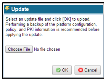
Click Choose File to open a window where you browse the system and select the update file to use. Click OK, and the file is checked; if valid, it is copied to the system and applied.
2.6 Venafi Trust Protection Platform (TPP)
2.6.1 Prerequisites
Venafi TPP requires the following in order to be installed:
Windows Server
Microsoft SQL Server Database
Hardware Security Module (if one will be used)
Microsoft .NET Framework
2.6.2 Installation
We installed Venafi TPP on Microsoft Windows Server 2012. Before starting the Venafi TPP installation, make sure you have configured your database and HSM.
The installation can be automated via a configuration file or manually performed with an installation wizard. The automated installation configuration file for installation into the production environment is typically created based on the Venafi TPP deployment in the DEV testing environment and placed in the user acceptance environment to formally test it. We recommend using the automated installation to reduce the possibility of errors during the installation into the production environment.
Because we were only configuring a single server in our lab environment, we manually installed and configured the product using the wizard. To install the Venafi TPP binaries and supporting files using the wizard, follow steps 1-7 in the Venafi Trust Protection Platform Installation Guide chapter titled “Installing using the Venafi Configuration Console wizard.”
Following step 7, the Venafi Configuration Console is automatically launched and is explained in steps 8-22 where specific integrations with the HSM and database are performed. We performed the following steps in our implementation:
At the prompt for first time or existing installation, select “first-time installation.”
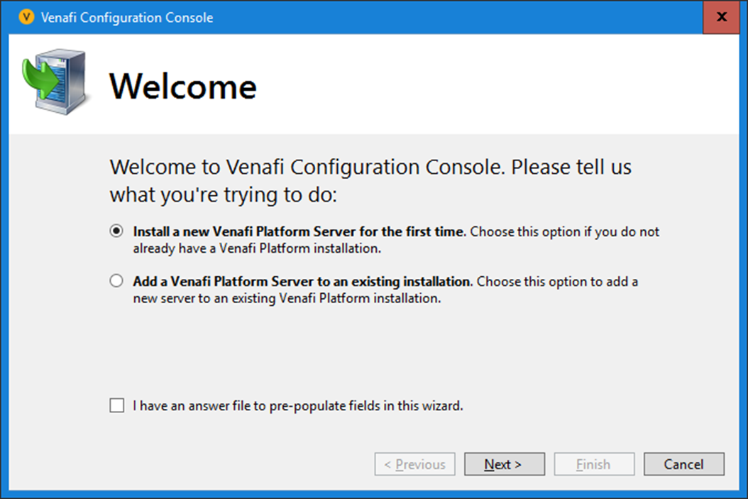
The Venafi Certificate Manager manages TLS server certificates, so it was selected. The Mobile Certificate and SSH Key Managers were not enabled.
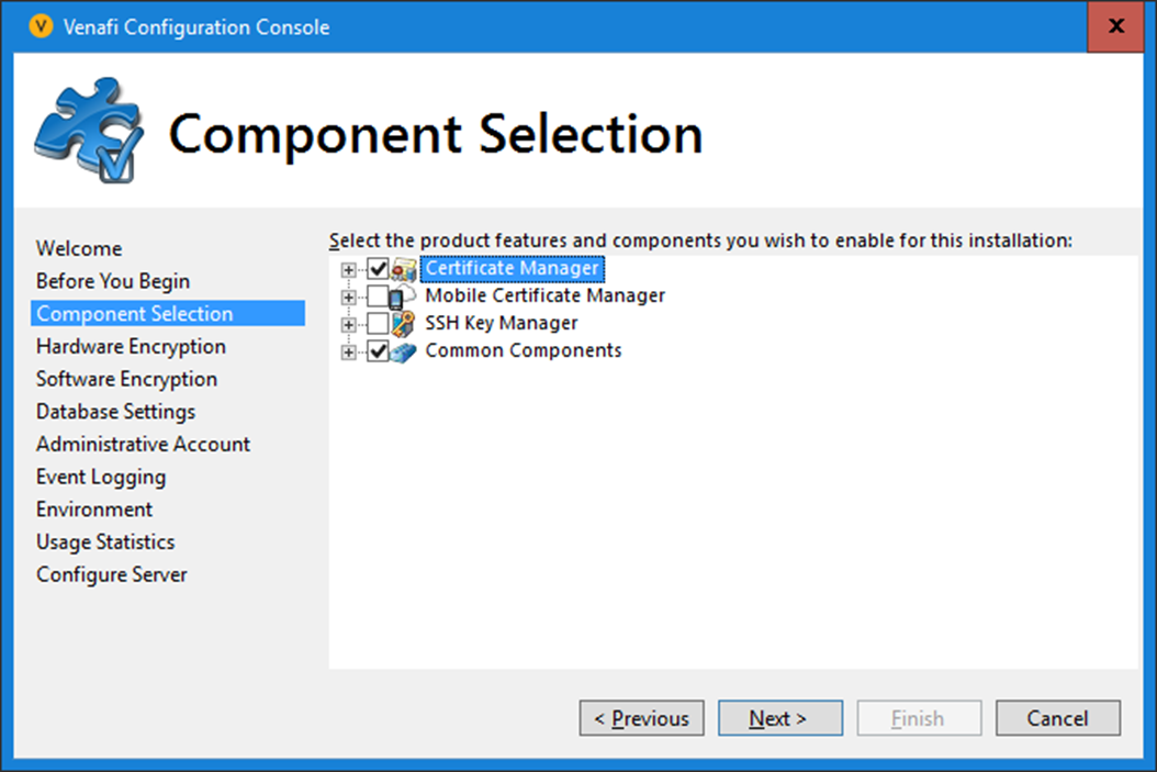
We recommend using an HSM with Venafi TPP to protect the symmetric key that encrypts private keys and credentials in the Venafi TPP database. In our implementation, we integrated with the Thales TCT HSM. We entered the following configuration:
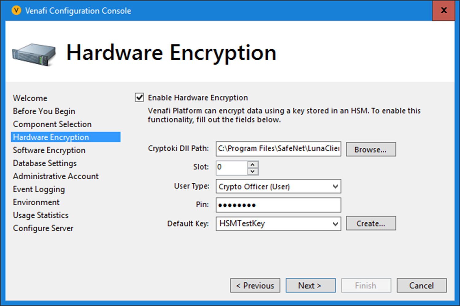
Windows authentication was used to authenticate to Microsoft SQL Server from Venafi TPP. Windows authentication is recommended, because it consolidates user account management, including control of password rules, failed logins, etc.
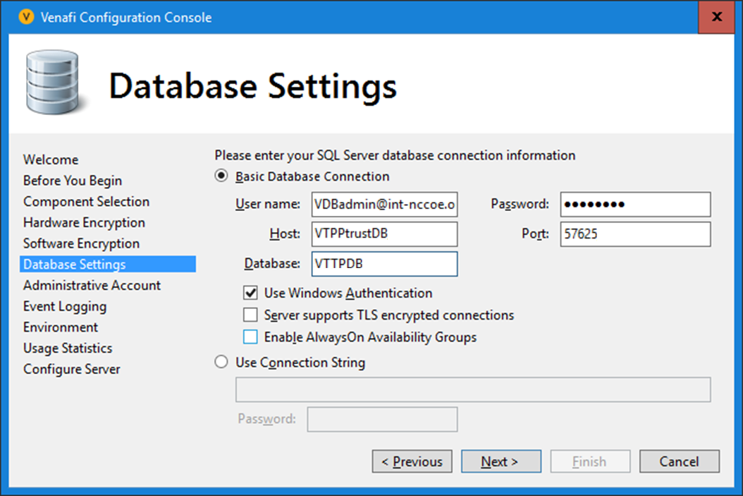
The initial Master Administrator account username was set to “admin,” and the password was also set.
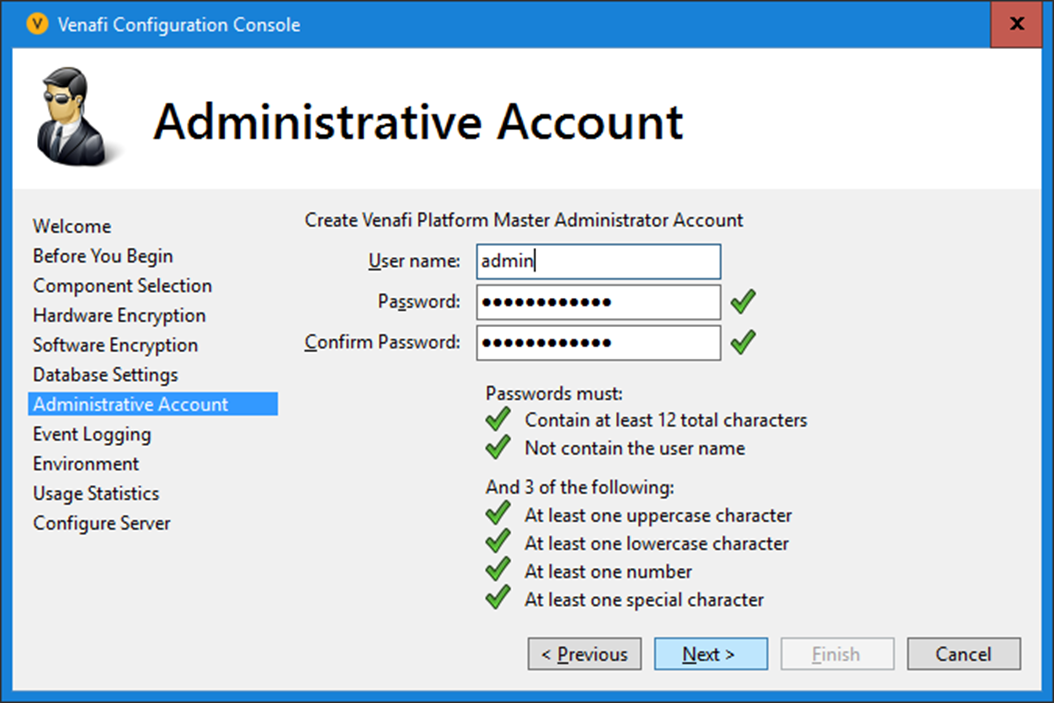
The Venafi TPP server was configured to process logs, as it was the only server in the environment.
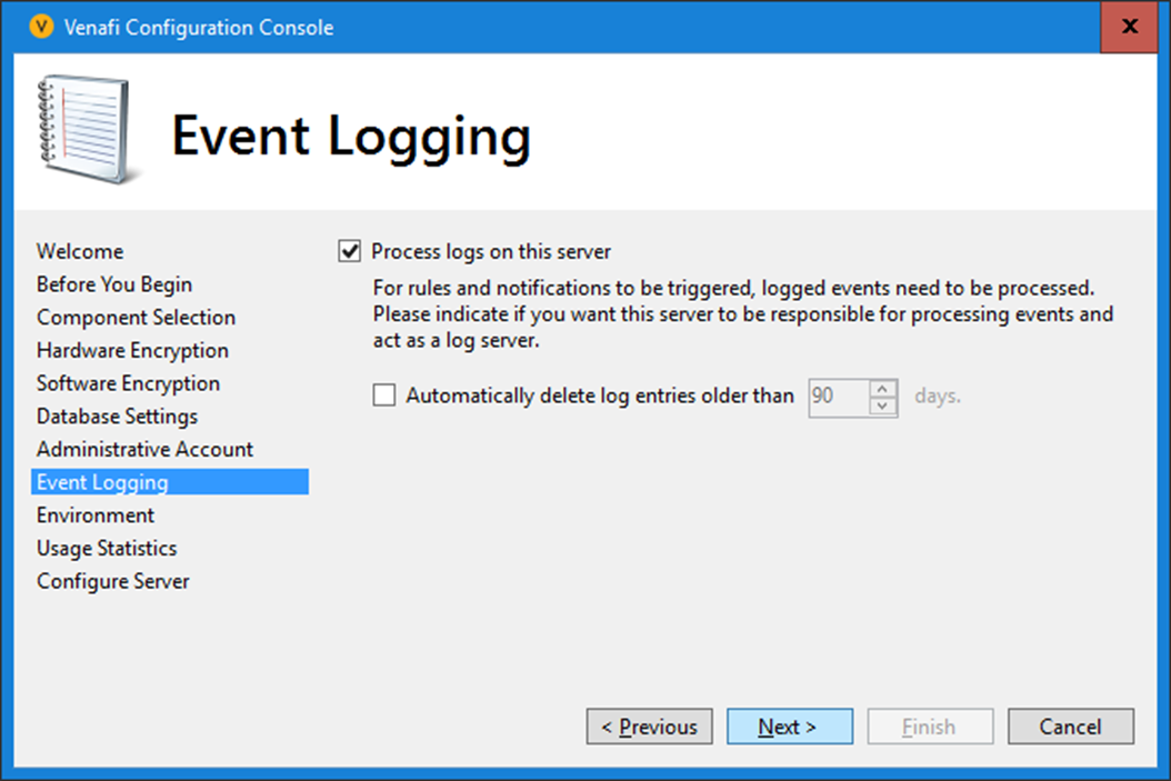
The organization name was set to “NCCoE”; the environment was set to “Test.”
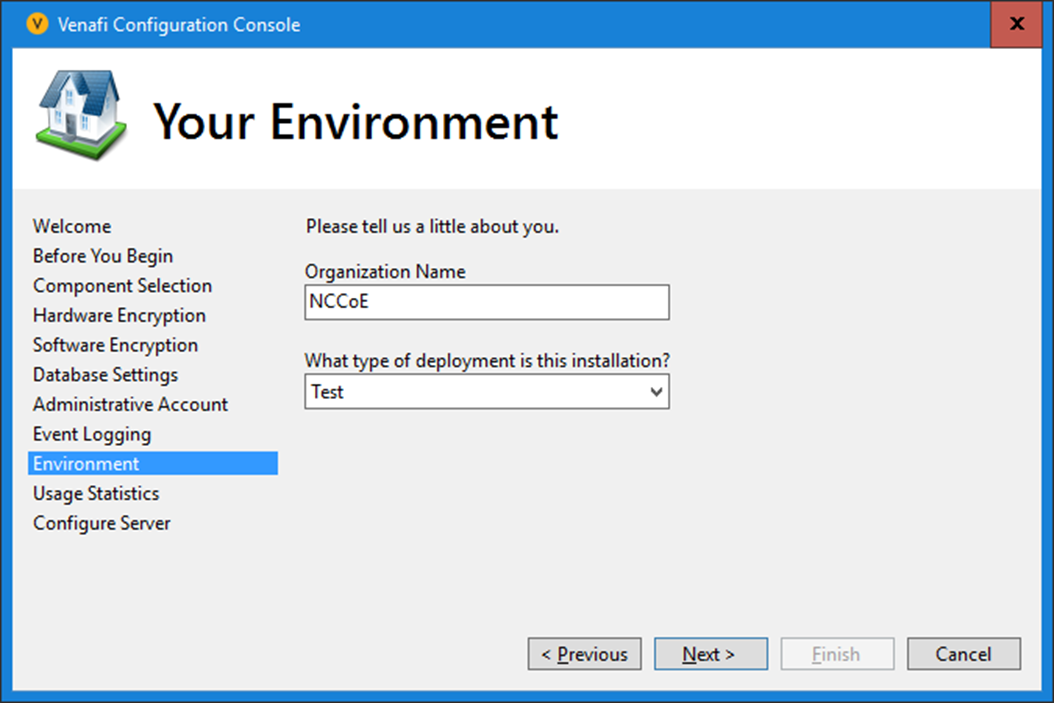
The collection of usage statistics was enabled.
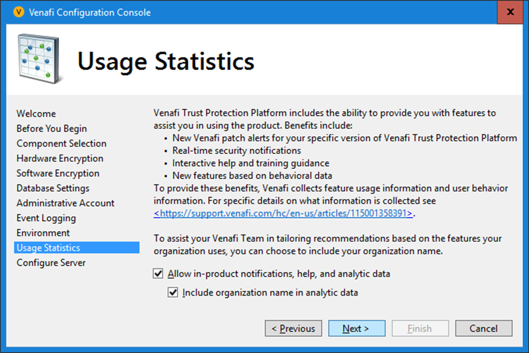
The default log file location was used.
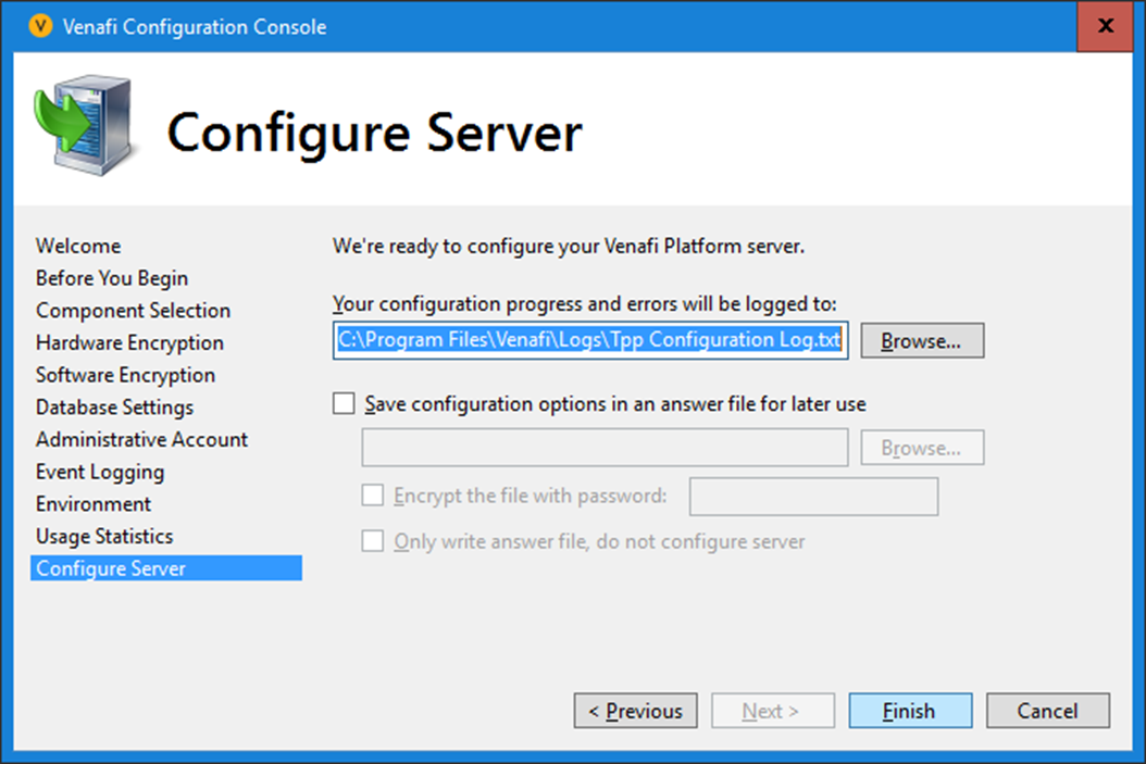
The Finish button was selected, and the configuration of the Venafi TPP server was completed successfully.
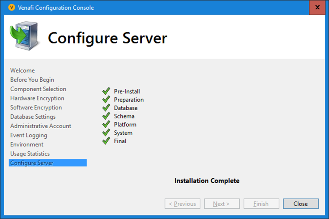
2.6.3 CA Integration
In our implementation, we integrated Venafi TPP with two CAs: DigiCert was used for publicly trusted certificates, and Active Directory Certificate Services for internally trusted certificates.
2.6.3.1 DigiCert
To configure integration with DigiCert so that Venafi TPP can automatically enroll for and retrieve certificates, follow the instructions in the “DigiCert CertCentral” section of the Venafi Trust Protection Platform Certificate Authority and Hosting Platform Integration Guide.
In our implementation, we used DigiCert Multi-SAN SSL certificates. The following configuration was used:
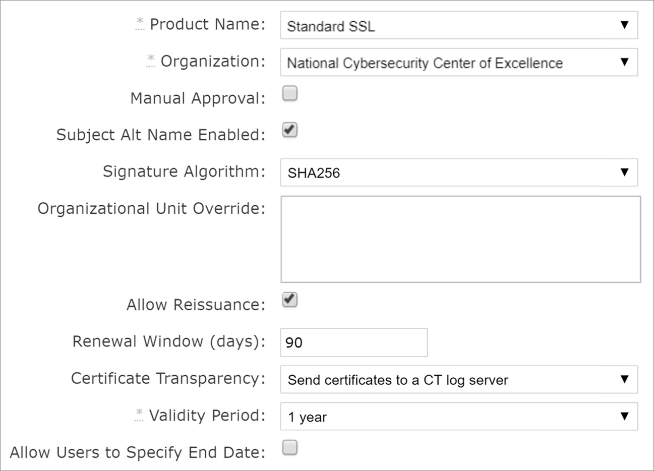
2.6.3.2 Active Directory Certificate Services
We used Microsoft ADCS to issue certificates to TLS servers inside the lab firewall. To configure integration with ADCS so Venafi can automatically enroll for and retrieve certificates, follow the instructions in the “Microsoft Active Directory Certificate Services (ADCS) - Enterprise and Standalone—CA template configuration” section of the Venafi Trust Protection Platform Certificate Authority and Hosting Platform Integration Guide.
In our implementation, we configured the host name, service name, and credential information in Venafi TPP to access the ADCS Issuing CA:
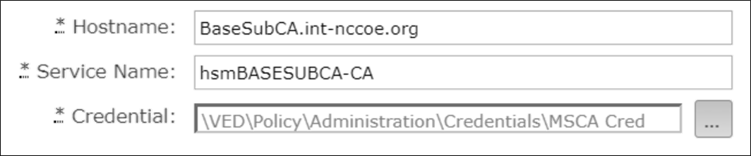
In our implementation, a certificate template named “VenafiRSAWebServer” was configured in ADCS to issue TLS server certificates. The CA template object we used in Venafi TPP to request certificates pointed to this template in ADCS and had the following configuration:
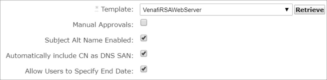
We recommend enabling “Subject Alt Name Enabled” and “Automatically include CN as DNS SAN,” as SANs in lieu of using CNs. Including a CN and SAN in certificates ensures backward compatibility with older clients that only support CNs and compatibility with newer clients that require SANs.
2.6.4 Folder Creation
To create a folder hierarchy for organizing certificate, application, and device objects, refer to the section titled “Managing your policies (folders)” in the Venafi Trust Protection Platform Administration Guide. The following folder structure was created in our implementation of Venafi TPP to match the three ficticious departments of certifciate owners in the lab:

2.6.5 Custom Fields
Follow the instructions in the section titled “Working with Custom Fields” in the Venafi Trust Protection Platform Administration Guide to define additional metadata fields for certificates and other objects. Two custom fields were defined in our Venafi TPP implementation: Biz Owner and Cost Center.
We configured the Biz Owner custom field with a field type of “Identity” to allow the selection of user identities in AD.
The Cost Center custom field was configured with a “String” field type, including a regex to validate that the cost centers that were entered matched the pattern of two letters, one dash, and four numbers. (e.g., AB-1234). A custom error message displays if a cost center doesn’t match the regex pattern entered by a user.
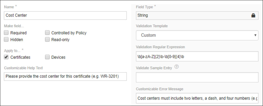
2.6.6 Assigning Certificate Owners
The assignment of certificate owners was done with AD groups Venafi TPP folders in our implementation, to ensure new certificates automatically had the correct owner assigned. The AD groups were created to represent the certificate owners in the four fictitious departments in our implementation. These groups were assigned as contacts and granted permissions at the folder level.
2.6.6.1 Contacts
For information about assigning Contacts to folders in Venafi TPP, refer to the section titled “General configuration options” in the Venafi Trust Protection Platform Administration Guide. Each certificate owner AD group was assigned as a contact to their respective Venafi TPP folder, so they would receive notifications (e.g., impending expirations, errors, etc.).
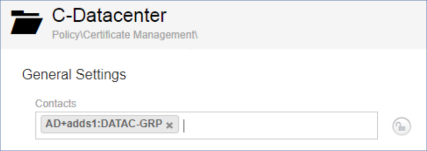
2.6.6.2 Permissions
For instructions on assigning permissions in Venafi TPP, refer to the section titled “Assigning permissions to objects in Aperture” in the Venafi Trust Protection Platform Administration Guide. In our implementation, we assigned each group representing a certificate owner View, Read, Write, Create, Delete, Rename, Associate, and Revoke.
For example, the DATAC-GRP was assigned the following privileges to the C-Datacenter folder in our implementation of Venafi TPP.
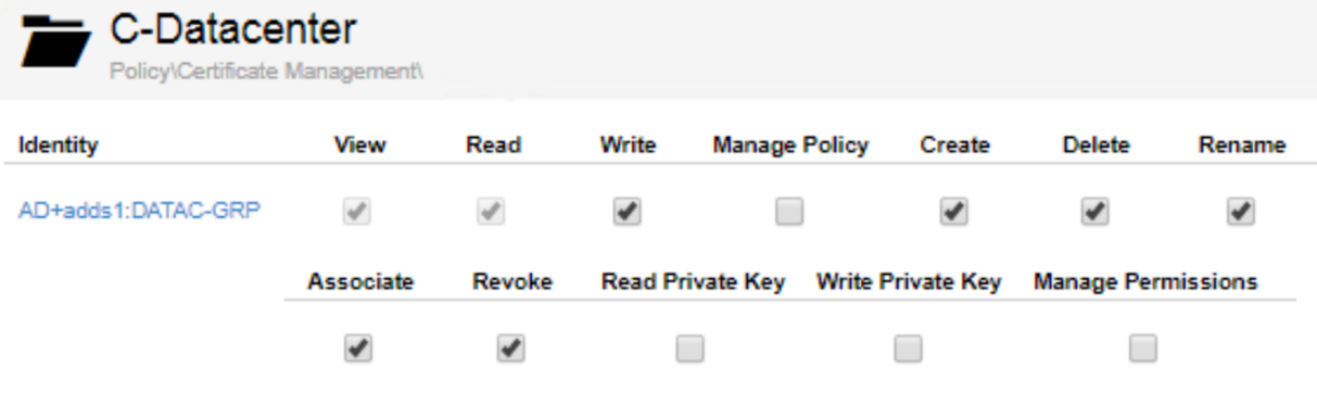
2.6.7 Setting Policies
For information about defining policies on folders in Venafi TPP, refer to the chapter titled “Using policies to manage encryption assets” in the Venafi Trust Protection Platform Administration Guide.
In our Venafi TPP implementation, the following policies were set:
The Organization, City/Locality, State/Province, and Country fields within Subject DNs were locked on a top-level folder, so that those values were required in certificates across all groups.
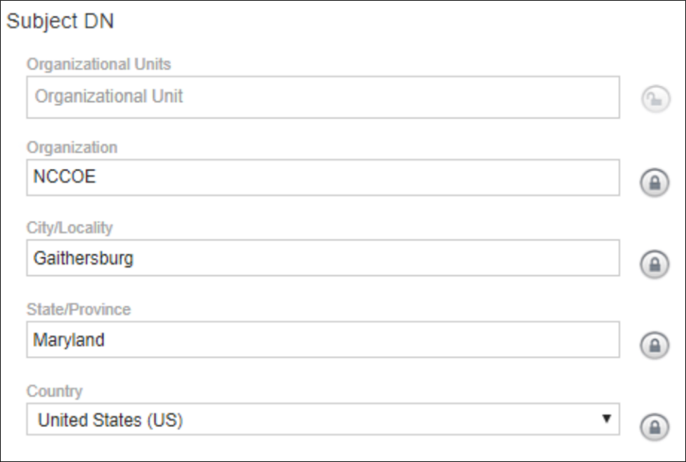
Specific domains were placed on an allowlist. See Section 2.6.8 of this document, the Establishing a Domain Allowlist for more information.
Approvers were assigned and locked at the folder level. See the “Workflow – RA Reviews” Section 2.6.9 of this document for more information.
The key length was set to 2048 on the Certificate Management folder and locked.

The following policies for certificate authorities were configured:
The internal Issuing CA was enforced on the following folders to ensure only internally issued certificates could be used:
DMZI
Datacenter
Datacenter Secure
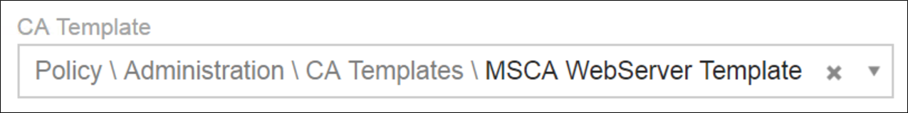
The publicly trusted DigiCert Mulit-SAN CA was enforced on the DMZE folder to ensure only publicly trusted EV certificates could be provisioned to the public facing interfaces of the F5 LTM.
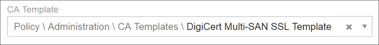
2.6.8 Establishing a Domain Allowlist
To limit security exposure, control the domains for which certificates can be issued. For instructions on configuring the domains for which certificates can be requested in Venafi TPP (establishing a domain allowlist), refer to the section titled “To configure certificate policy on a folder” in the Venafi Trust Protection Platform Certificate Management Guide.
In our implementation, we allowed two internal domains (int-nccoe.org and ext-nccoe.org) for all folders that contained internal resources in Venafi TPP.
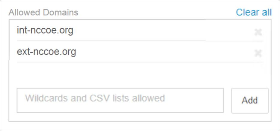
In the DMZE folder containing all the external resources, we also allowed the externally accessible domain (tls.nccoe.org).
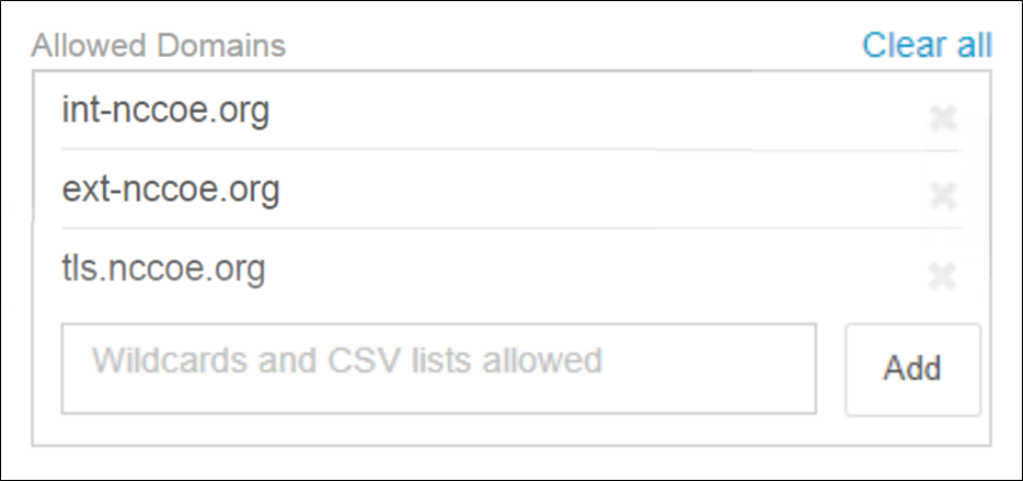
2.6.9 Workflow – RA Reviews
For instructions on configuring workflow gates in Venafi TPP, refer to the section titled “Creating a certificate workflow” in the Venafi Trust Protection Platform Certificate Management Guide. In our implementation, we established a workflow gate for the Datacenter Secure zone. To do so, perform the following steps:
Create a workflow object. Assign the stage to “0.” Select “Approver assigned to object” for Request Approval From.
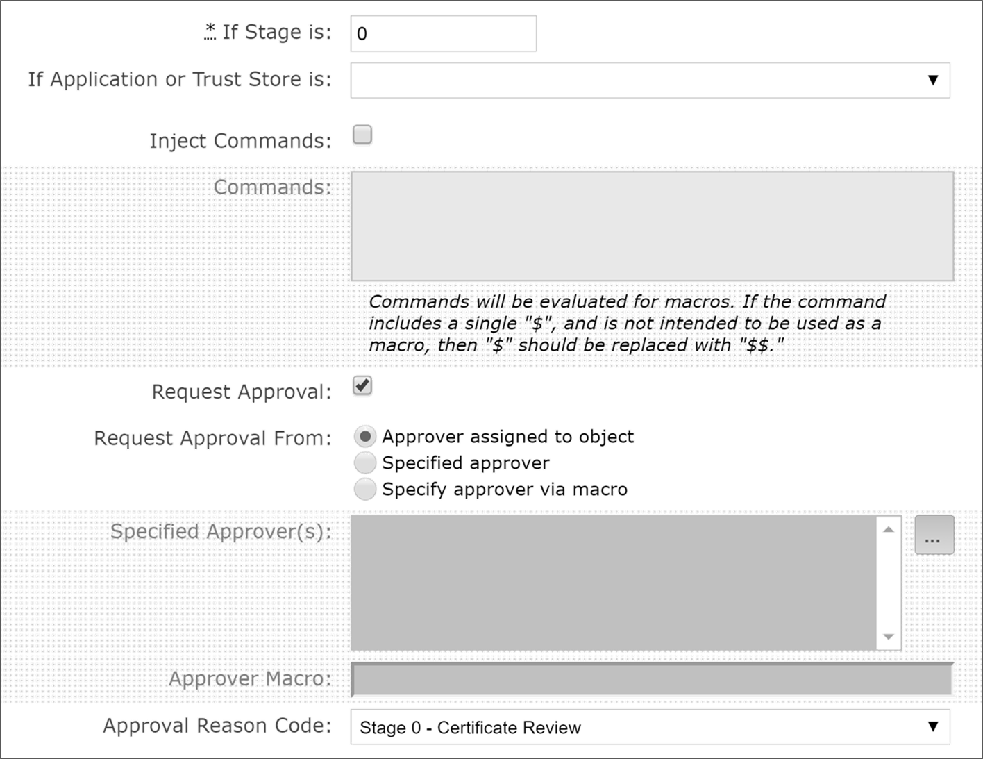
Assign the workflow to the Datacenter Secure folder policy.
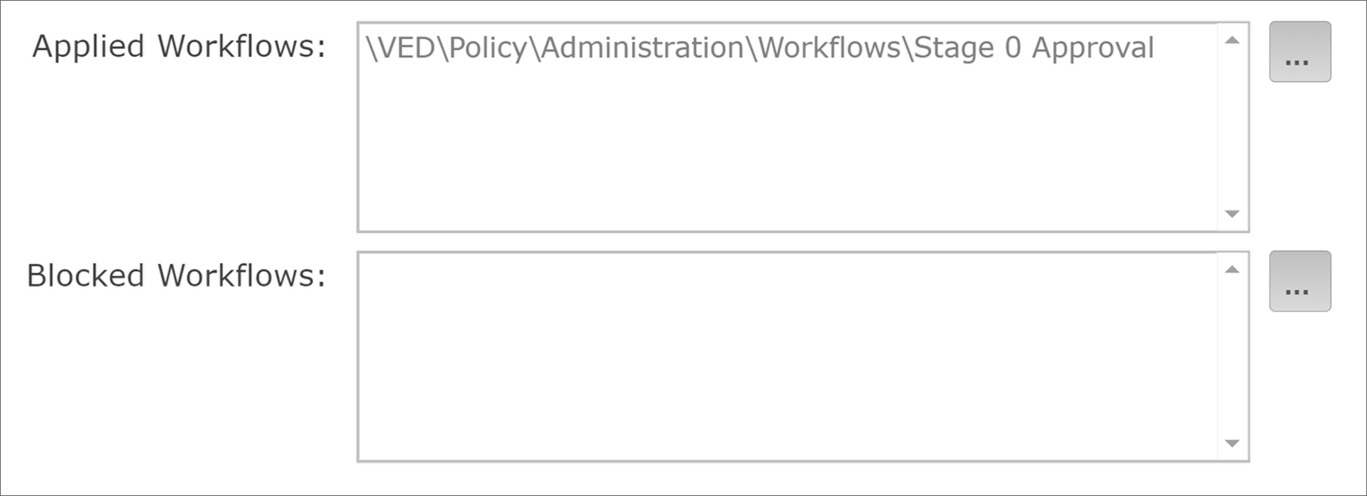
Assign the appropriate AD group (datacs_apprvr) to the Approver(s) for certificates on the Datacenter Secure folder.
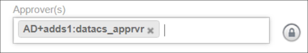
2.6.10 CA Import
Once folder structure, policies, certificate owners, and other configurations are completed, begin building the inventory of certificates—start by importing certificates from the ADCS-issuing CA.
For instructions on configuring imports from ADCS, refer to the chapter titled “Importing certificates from a certificate authority” in Venafi Trust Protection Platform Administration Guide.
In our implementation, we configured Venafi TPP to import certificates from a particular ADCS template named, “WebBulkCertTemplate.” We included expired—not revoked—certificates. We chose not to define any placement rules and placed all certificates into a single folder named ADCS Import.
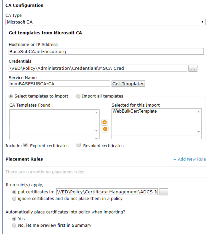
A total of 523 certificates were imported from the ADCS issuing CA.
2.6.11 Network Discovery
It’s possible to accomplish network discovery scanning for TLS server certificates in several ways, including using existing vulnerability assessment tools or the certificate management solution. In our implementation, we used Venafi TPP to perform network discovery scans using two different methods: scanning using Venafi TPP servers and the Scanafi utility.
2.6.11.1 Venafi TPP Server
In our implementation, we used Venafi TPP servers to perform network discovery scans in the Datacenter and Datacenter-Secure network zones. For instructions on performing network discoveries with Venafi TPP servers, see the chapter titled “Discovering certificates and keys” in the Venafi Trust Protection Platform Certificate Management Guide.
2.6.11.2 Scanafi
For information on using Scanafi to perform network discovery scans, refer to the section titled “Automatically calling Discovery/Import from Scanafi” in Venafi Trust Protection Platform Web SDK Developer’s Guide.
In our implementation, we installed Scanafi on a Fedora Linux system in the DMZ network zone. The following command was used to execute a network discovery scan.
./scanafi_linux_x64 --tppurl=https://venafi1.int-nccoe.org \
--tppuser=vscanuser --tpppass=******** --range=192.168.4.0/23 \
--zone="\\VED\\Policy\\Certificate Management\\UNKNOWN ORIGIN" \
--certsonly
2.6.12 Identify Certificate Risks/Vulnerabilities
Following the import of certificates from the ADCS-issuing CA and the network discovery scans, we used the Venafi TPP dashboard to identify certificate risks and vulnerabilities. The following shows the dashboard micro-widgets for our implementation.
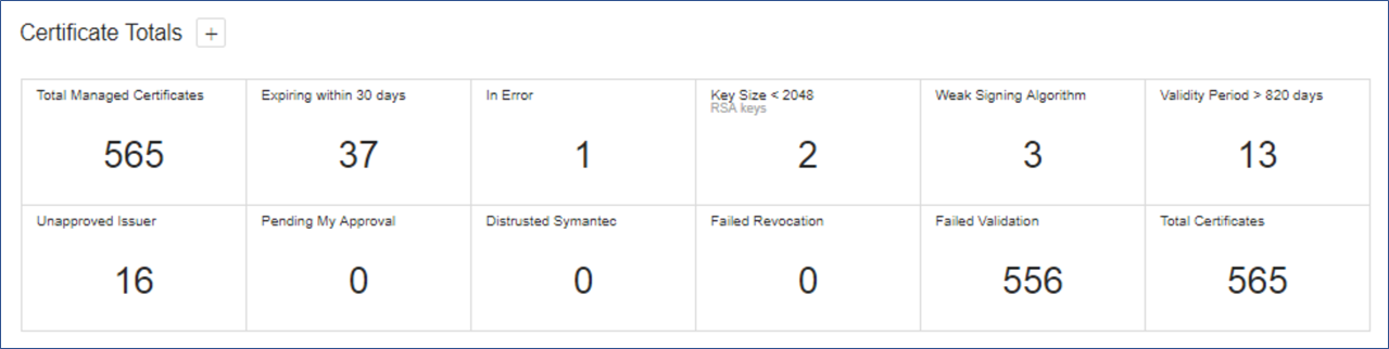
We used this information to identify certificates not compliant with policy (e.g., certificates issued by unapproved CAs or with weak lengths), so they could be replaced.
The dashboard was also used to identify outage risks related to certificate expirations. The following figure displays the Expiration widget of the dashboard that shows the expiration profile for certificates in our implementation.
Figure 2‑2 Venafi Dashboard Expiration Widget showing the Certificate Expiration Profile
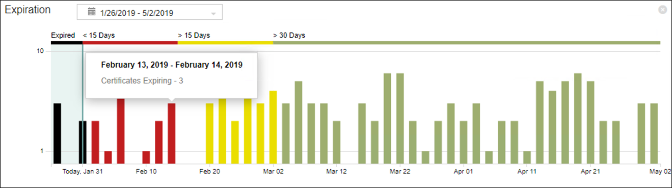
2.6.13 Automate Management
2.6.13.1 F5 BIG-IP LTM
2.6.13.1.1 Discover Existing F5 Certificates and Manage
Venafi TPP can automatically discover existing certificates and configuration through its Onboard Discovery feature. Because most organizations have F5 systems with existing certificates installed, this is a common process for F5 systems we used in our implementation, which included the following steps:
Create an Onboard discovery job to discover certificates on F5 systems. For instructions on how to create Onboard Discovery jobs, refer to the section titled “Using Onboard Discovery” in the Venafi Trust Protection Platform Certificate Management Guide.
Create a device object in Venafi TPP with the address and credentials for the F5 device on which you want to discover and manage certificates.
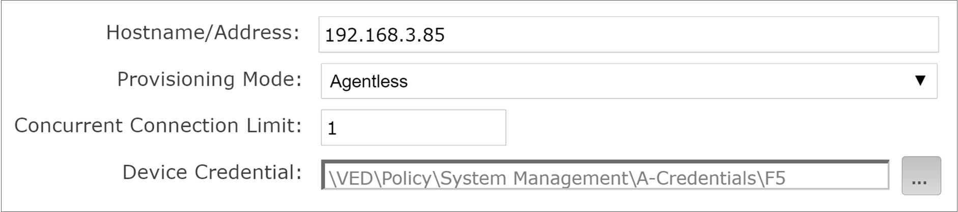
Run the F5 Onboard Discovery job by clicking Run Now.
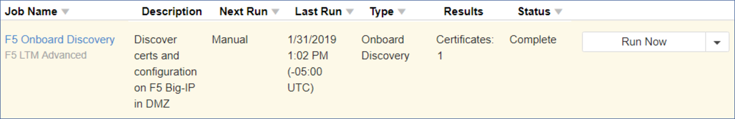
Ensure the discovered certificate(s) are set to automatically renew when they are nearing expiration.
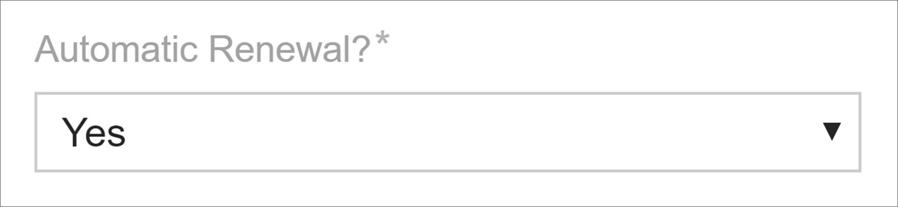
With this discovered configuration, including the certificate, Venafi TPP was set to automatically replace the existing certificate with a new certificate prior to expiration.
2.6.13.1.2 Install a New Certificate on F5
In our implementation, Venafi TPP was used to enroll for and install a new certificate on the F5 LTM in the DMZ. The following steps were used to perform these operations:
Create a new certificate object in the Venafi TPP Aperture console.

Select the appropriate folder.

Select a name for the certificate.
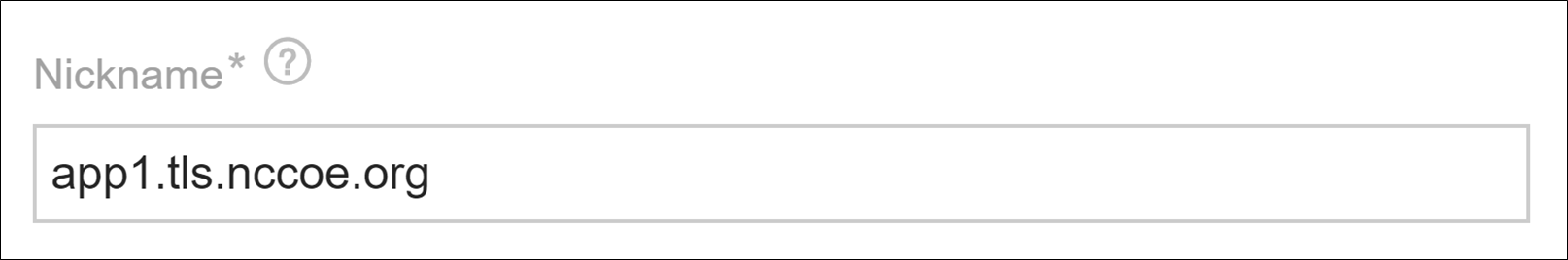
Select the “Provisioning” Management Type to configure the certificate for automated management.
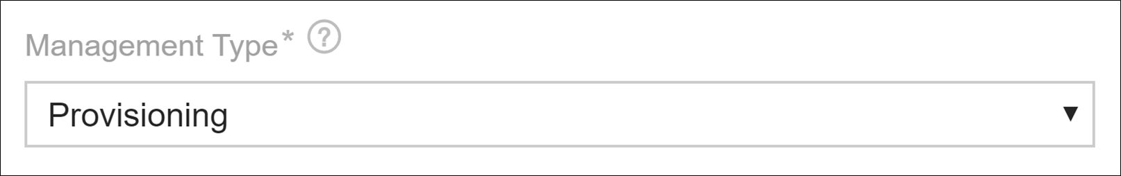
Enter the CN for the certificate.
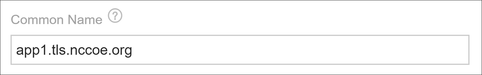
Enter the SANs for the certificate.
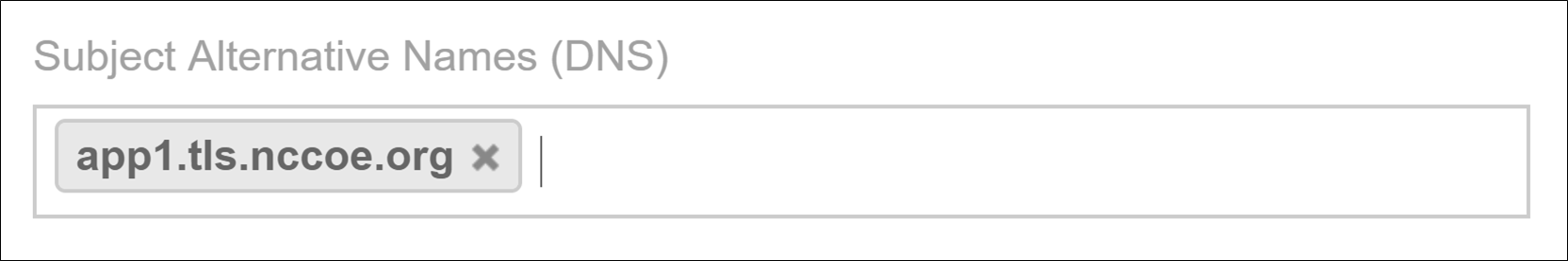
Configure the certificate for automatic renewal and installation when it is nearing expiration.
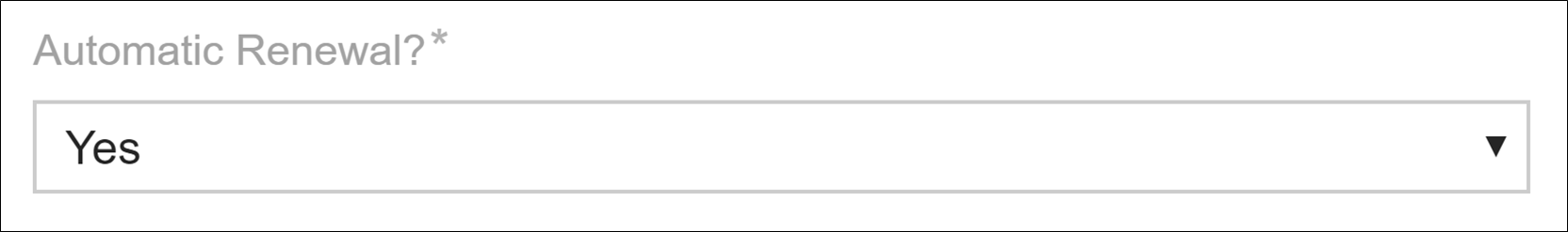
Add a new installation for the certificate, and indicate that management will be automated for that installation.

Select the F5 device where the certificate will be installed.
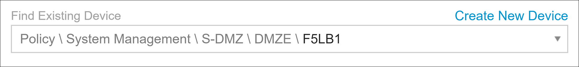
Indicate that the Installation Type is “F5 BIG-IP Local Traffic Manager.”
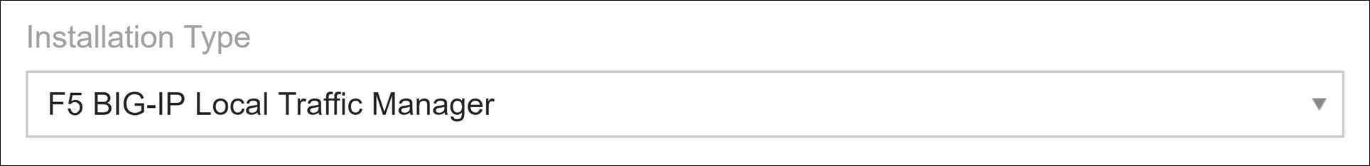
The certificate we were installing was not for securing the administrative interface to the F5 LTM, therefore, we selected “No” for the Device Certificate.

We indicated that Venafi TPP should update the profile when the new certificate was installed. This ensures the configuration was properly set up to use the new certificate.

We instructed Venafi TPP to install the CA certificates with the new certificate—enabling clients connecting to the F5 to validate the certificate signature with the chain.

We chose to have Venafi TPP bundle the CA certificates with the new certificate (in the same file on the F5 device).

An HSM was not installed on the F5 device we were using, so we indicated this to Venafi TPP.

We instructed Venafi TPP to overwrite the existing certificate each time it installed a new certificate (prior to expiration).

We instructed Venafi TPP to delete the existing certificate when the new certificate was installed.

To ensure the certificate was associated with the correct SSL profile on the F5 LTM, we configured the following:
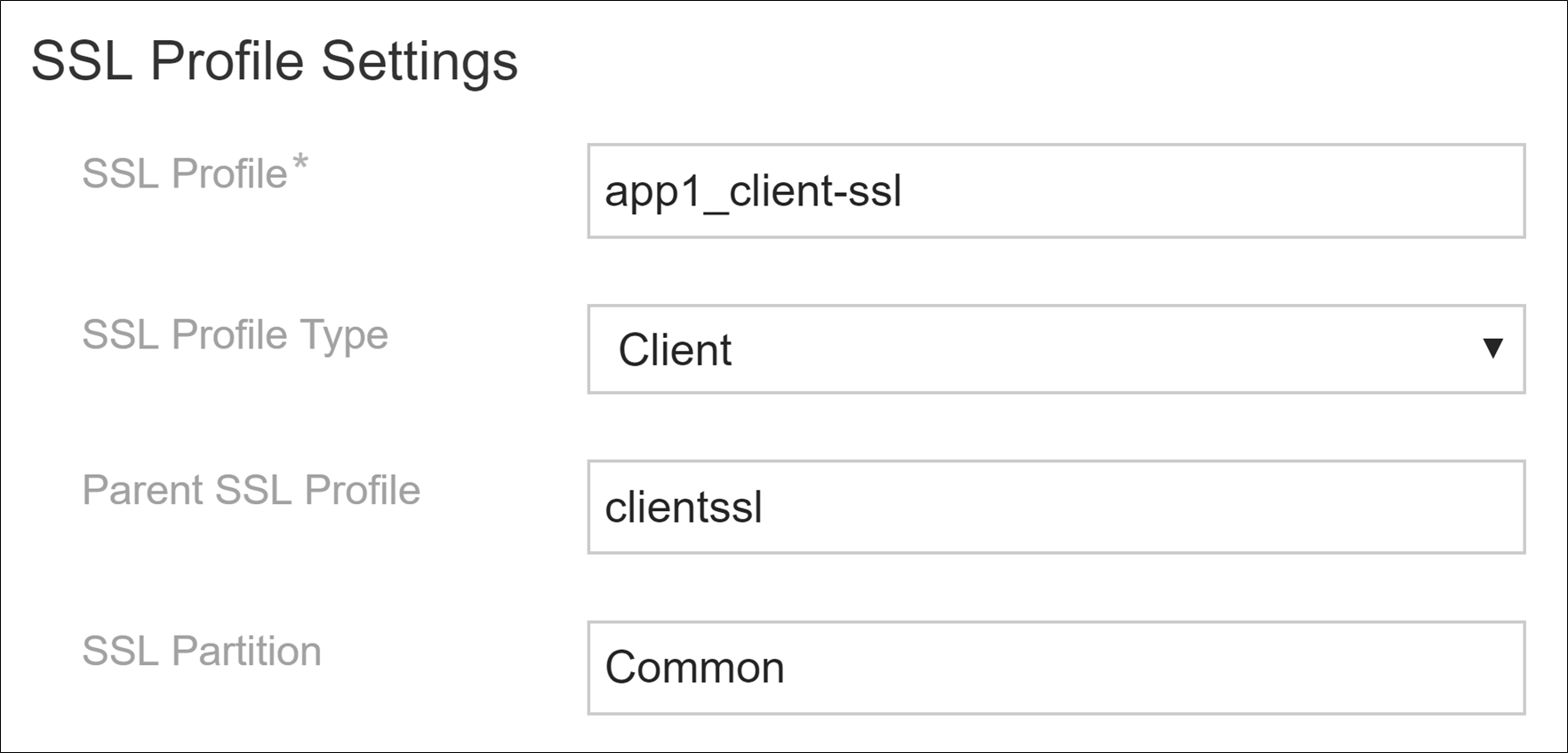
We provided Venafi TPP information about the virtual server where the certificate should be associated.
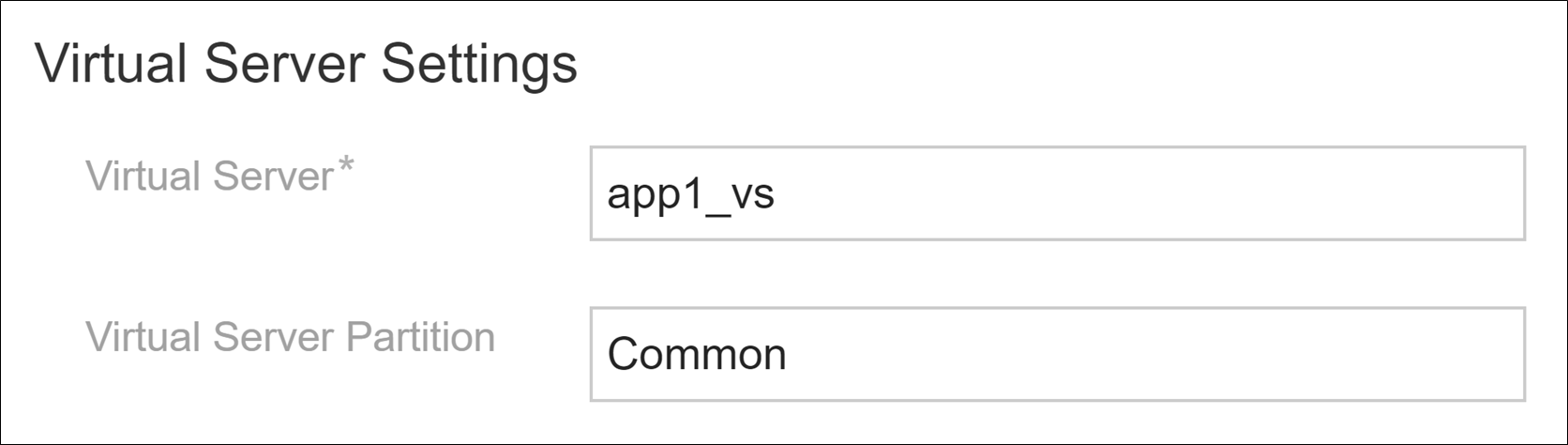
We indicated to Venafi TPP that we did not use mutual authentication or other advanced features on the F5 LTM.

After configuring these settings, we clicked Save.

Click Renew Now on the certificate to start to enroll a new certificate and to install it on the F5 LTM with these configuration settings.
2.6.13.2 Microsoft IIS – Agentless
The Microsoft IIS system we used in our implementation to demonstrate automated management had an existing certificate. Venafi TPP can automatically discover existing certificates and configuration through its Onboard Discovery feature. Consequently, the following process was used:
Create an Onboard discovery job to discover certificates on Microsoft IIS systems. For instructions on how to create Onboard Discovery jobs, refer to the section titled “Using Onboard Discovery” in the Venafi Trust Protection Platform Certificate Management Guide.
Confirm Windows Remote Management (WinRM) service was running on the Windows server hosting IIS.
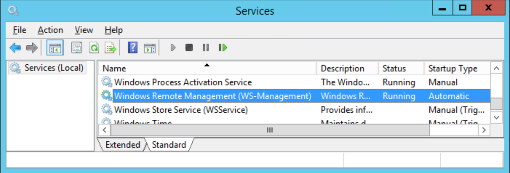
Enable WinRM at the command line.
C:\>winrm quickconfigCreate a device object in Venafi TPP with the address of the Windows server hosting IIS and a credential for Venafi TPP to authenticate to the system.
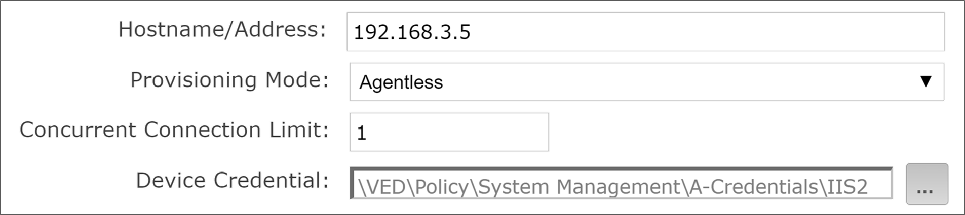
Execute the IIS Onboard Discovery job that applied to the folder where the device was located. The certificate and binding configuration on IIS were discovered.
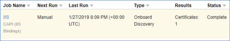
The certificate is discovered.

In addition, IIS binding information is discovered, so that all the necessary configuration for automated management is populated in Venafi TPP.
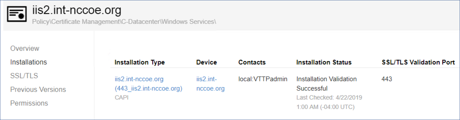
To ensure the certificate automatically renews and is replaced when nearing expiration, confirm the certificate was set to automatically renew prior to expiration.
2.6.13.3 Microsoft IIS with Thales TCT HSM – Agentless
The Venafi TPP server was used to remotely trigger the generation of a key pair and CSR on the Thales TCT HSM. The HSM is connected to the Microsoft IIS server in the Datacenter Secure zone and can enroll a certificate using the generated CSR. It can also install the certificate in the Windows server with the proper configuration for the Microsoft IIS server. The following steps are used to perform these operations:
Ensure the Thales TCT HSM client is installed and configured on a Windows server hosting Microsoft IIS. See Section 2.2.2.4 for instructions.
Create a new certificate object in the Venafi TPP Aperture console.
Select the appropriate folder.

Select a name for the certificate.
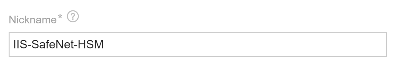
Select the “Provisioning” Management Type to configure the certificate for automated management.
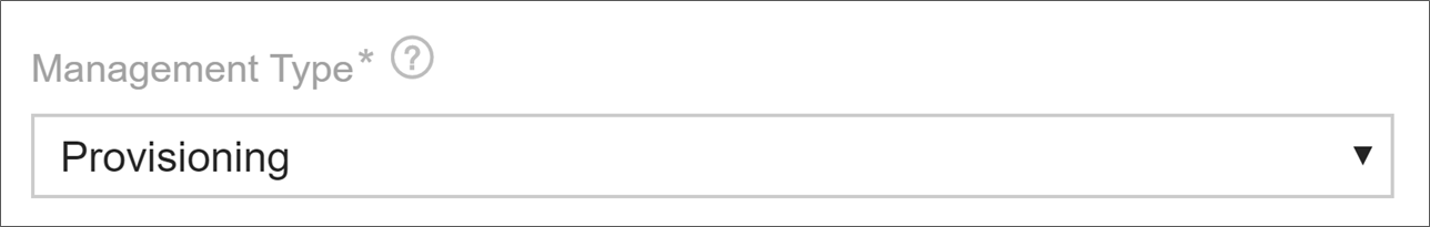
Enter the CN for the certificate.
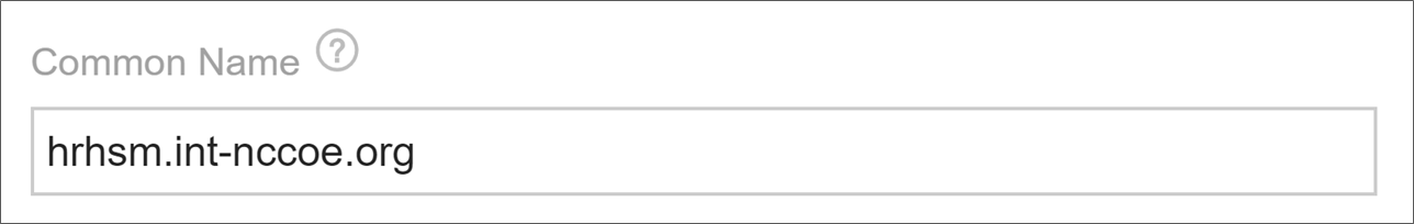
Enter the SANs for the certificate.
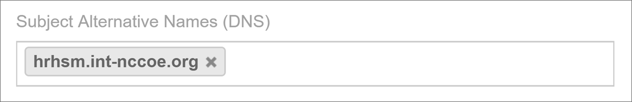
Configure the certificate for automatic renewal and installation when it is nearing expiration.
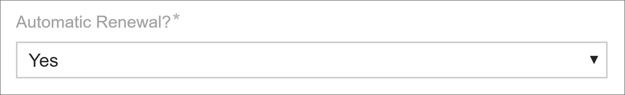
Add a new installation for the certificate and indicate that management is automated for that installation.
Enter the address for the device where the certificate will be installed.
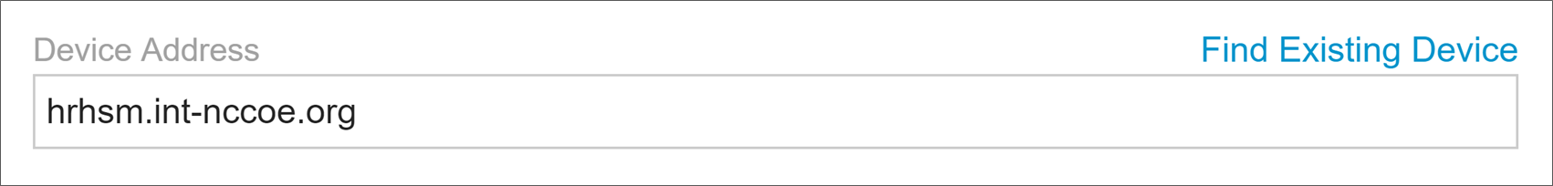
Select the folder where the device object should be created.
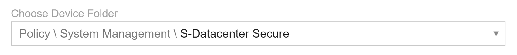
Indicate that the application type for the installation is “Windows CAPI & IIS.”
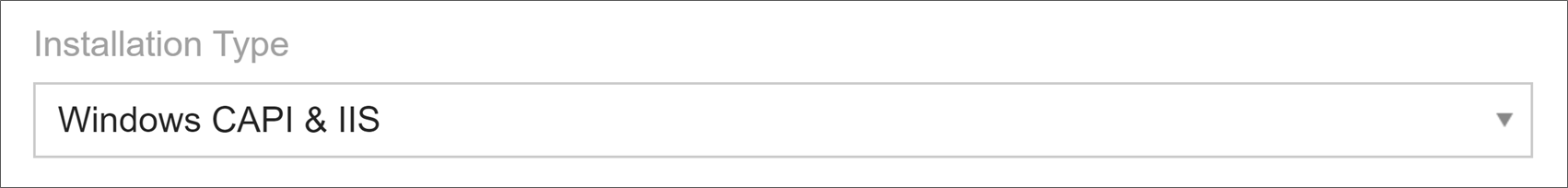
Select the credential to authenticate to the system for management operations.

Enter a CAPI-friendly name for the certificate to be installed.

Click Renew Now on the certificate to start generating a new key pair on the HSM and to start getting a new corresponding certificate.
2.6.13.4 Apache – Agentless
Create a new certificate object in the Venafi TPP Aperture console. For instructions on creating a new certificate, refer to “Creating a new certificate in Aperture” in Venafi Trust Protection Platform Working with Certificates.
Add an installation location for the certificate for the Apache where the certificate will be installed. For instructions on adding an Apache installation in Aperture, refer to the section titled “Creating an Apache application object” in the Venafi Trust Protection Platform Certificate Authority and Hosting Platform Configuration Guide. Notable configuration information that we used in our implementation, includes:
Set the private-key file location to correspond to the Virtual Host configuration on the Apache server.

Set the certificate file location to correspond to the Virtual Host configuration on the Apache server.

Set the CA certificate chain file location to correspond to the Virtual Host configuration on the Apache server.

Instruct Venafi TPP to update the CA chain.

Click Install in the Actions menu to deploy the certificate to the Apache system.
2.6.13.5 Apache – ACME
Venafi TPP was configured as an ACME server in our implementation to support ACME-based requests from internal systems. For instructions on using ACME with Venafi TPP, refer to the section titled “ACME integration with Trust Protection Platform” in the Venafi Trust Protection Platform Certificate Management Guide.
2.6.13.6 Configuring Venafi TPP for ACME
The following steps are needed for configuring Venafi TPP to request certificates using an ACME client.
Configure Venafi TPP to enable the ACME server.
The ACME server is not enabled by default in Venafi TPP.
When ACME is enabled, select the folder where ACME-enrolled certificates are placed.
Enter the address of the Venafi TPP server that will service ACME clients.
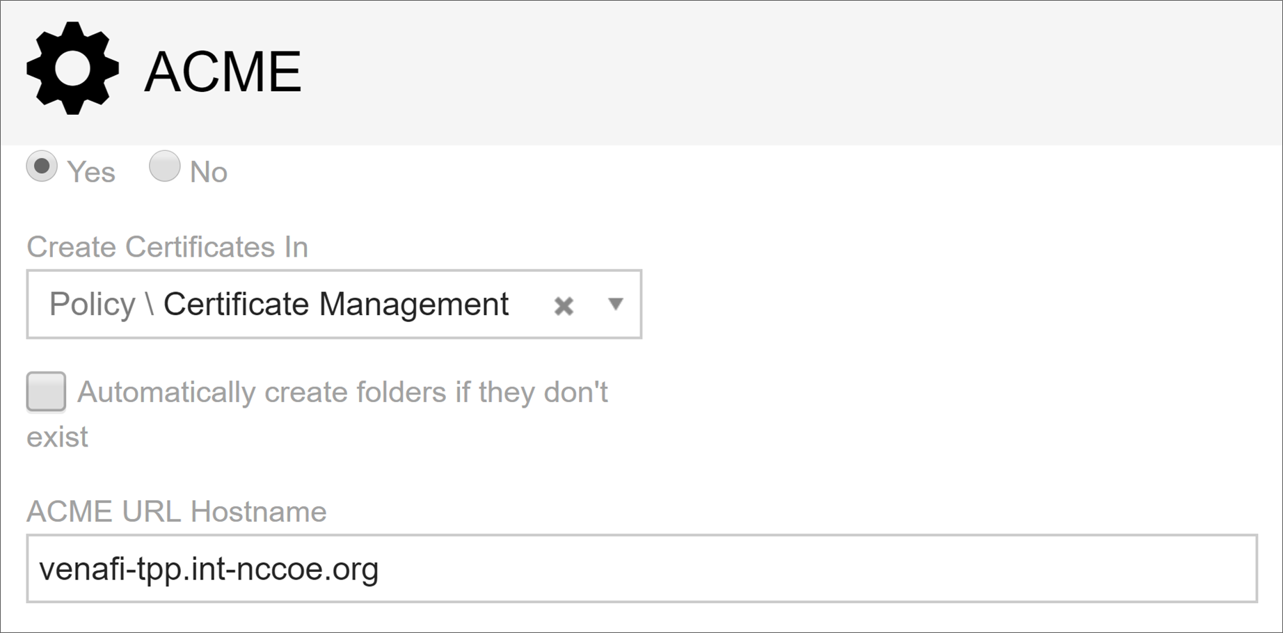
Assign an email address to the requesting account. The ACME protocol requires an email address be provided during the registration process. Venafi TPP must be able to find the entered email address in the local Venafi TPP identity directory or AD (depending on which directory is used).
2.6.13.7 Configuring Certbot for Apache
Certbot is the standard client use for ACME on many systems. Find instructions on installing certbot at the following address: https://certbot.eff.org/. We installed certbot on a Fedora Linux system to automate certificate requests and installation for Apache.
We performed the following steps in our implementation.
Ensure the virtual host is configured in Apache.
Install certbot for Apache.
sudo dnf install certbot certbot-apacheThe root certificate for the CA that issued the Venafi TPP server’s certificate must be trusted on the system where certbot is run. This is done by adding it to one of the following files depending on the OS:
/etc/ssl/certs/ca-certificates.crt", // Debian/Ubuntu/Gentoo etc.

/etc/pki/tls/certs/ca-bundle.crt", // Fedora/RHEL 6

/etc/ssl/ca-bundle.pem", // OpenSUSE

/etc/pki/tls/cacert.pem", // OpenELEC

/etc/pki/ca-trust/extracted/pem/tls-ca-bundle.pem", // CentOS/RHEL 7
Run certbot to request a certificate. A certificate was installed on the Apache system.
certbot certonly \
--server “https://venafi1.int-nccoe.org/vacme/v1/directory” \
--cert-name apache1 --domains apache1.int-nccoe.org \
--apache --email [email protected] --no-eff-email
2.6.13.8 Kubernetes
Instructions for installing, configuring, and using Kubernetes are available on https://kubernetes.io/.
We installed a three-node Kubernetes cluster on three CentOS Linux systems in the Datacenter network zone in our implementation. We installed the following for the Kubernetes deployment:
Docker version 18.09.3, build 774a1f4
kubelet, kubeadm, and kubectl v1.13.4
Weave (as our overlay network)
Once these components were installed, we installed and configured cert-manager in Kubernetes to automatically request certificates for ingresses in Kubernetes. We performed the following steps:
Verified a user account with Venafi TPP WebSDK access and permissions to the folder(s) where certificates are being requested from cert-manager (see the definition of the issuer below). We created a user named “vapirequester” in AD for this purpose. The account was granted Create, Write, Read, and View permissions to a folder named DevOps. We also granted that account WebSDK access.

Verified Jetstack Cert-Manager was installed with the necessary components to request certificates from Venafi TPP. This automatically creates a namespace named “cert-manager,” which we used for the rest of our configuration.
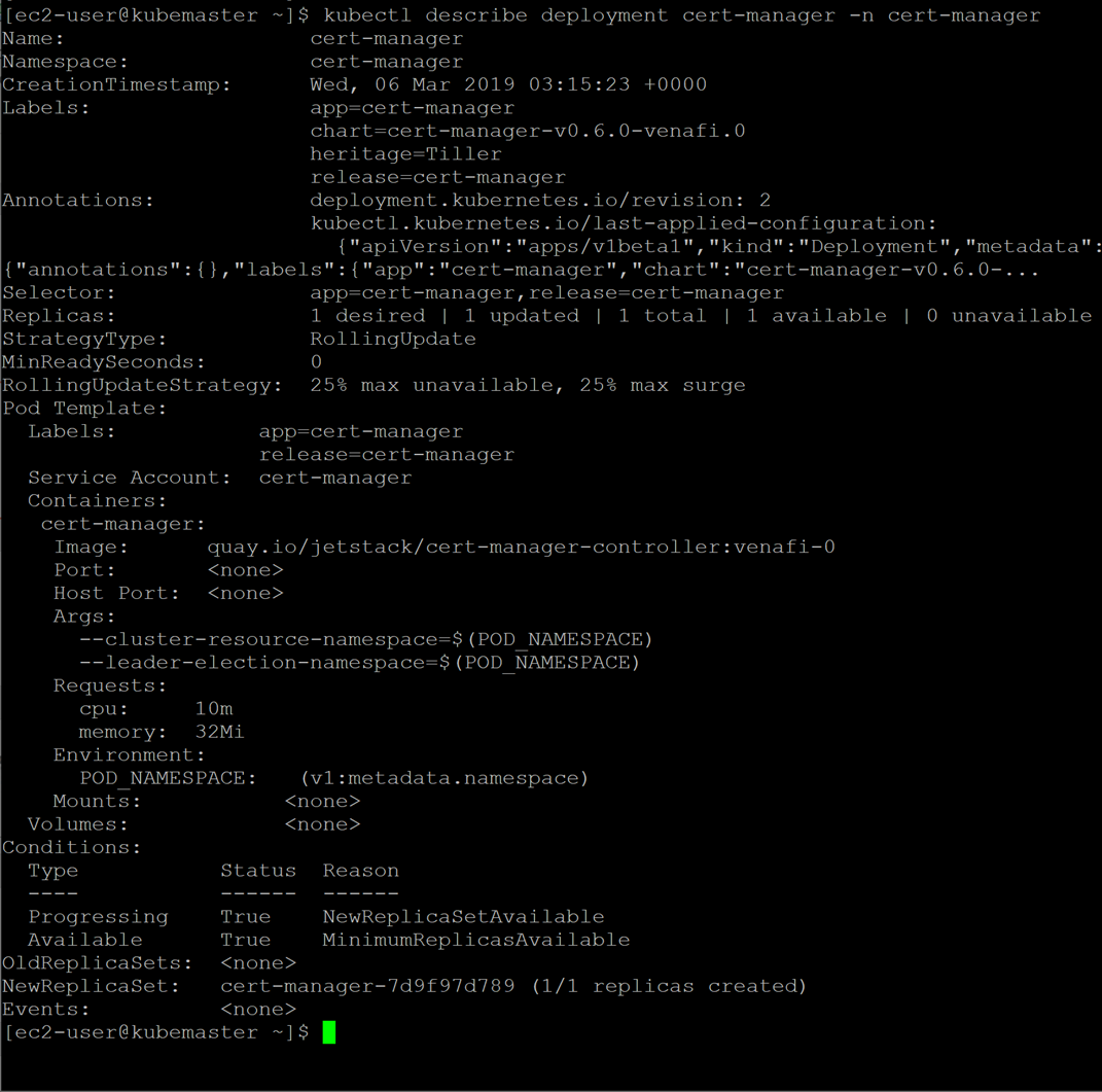
kubectl apply -f https://raw.githubusercontent.com/jetstack \
/cert-manager/venafi/contrib/manifests/cert-manager/with-rbac.yaml
Created Kubernetes secret for authenticating to Venafi TPP.
kubectl create secret generic tppsecret \

--from-literal=username='vapirequester' \

--from-literal=password='********' \

--namespace cert-manager
Copied the Root CA certificate that the certificate on the Venafi TPP chains up to (this is used by cert-manager to validate the Venafi TPP certificate). This was copied to a file named rootca.pem.
Generated a base64 representation of the Root CA certificate.
cat rootca.pem \| base64 \| tr -d '\n'Created a yaml file (tppvenafiissuer.yaml) for the configuration for a cert-manager issuer that points to Venafi TPP. Note that the base64 representation of the Root CA certificate is placed after “caBundle:” with a single space separating (there is no carriage return). The “zone” sets the folder where the requested certificate will be placed.
apiVersion: certmanager.k8s.io/v1alpha1
kind: Issuer
metadata:
  name: tppvenafiissuer
  namespace: cert-manager
spec:
  venafi:
  zone: 'Certificate Management\C-Datacenter\DevOps'
  tpp:
    url: https://venafi1.int-nccoe.org/vedsdk
    credentialsRef:
      name: tppsecret
    caBundle:
LS0tLS1CRUdJTiBDRVJUSUZJQ0FURS0tLS0tCk1JSUMvVENDQWVXZ0F3SUJBZ0lRSnBydys5NUMyNnh
Kd2FEeXFsWUhXekFOQmdrcWhraUc5dzBCQVFzRkFEQVIKTVE4d0RRWURWUVFERXdaU1QwOVVRMEV3SG
hjTk1UZ3dOekE1TWpNME1EUTVXaGNOTWpBd056QTVNak0xTURRNApXakFSTVE4d0RRWURWUVFERXdaU
1QwOVVRMEV3Z2dFaU1BMEdDU3FHU0liM0RRRUJBUVVBQTRJQkR3QXdnZ0VLCkFvSUJBUURaaHZxUXk3
ckZrTnlWenZxSW5GeE4ydVBLTEJRdzl1Mk5kb1NmTXhMTVU5TlB4UUcwOVNyT1V1SSsKYmhkckJNeEt
FbStzMm5PTUNtY3g2SDN1dGp0UmtWU2pxQVZkYnQrVkN0TmtQWlZYTlRKaWlkOFVlTmRYY1dDMQpjMk
M5RUVBNDVUOG94eG10TEkvd0l0N2RaMHpwVldxSitvT1VLVGFIZWpRTFcveUxYWkIvU3AvZzFuUmFOM
XhqCjFZVllRQ2dCMWxVZ0lGQ3lXUzJJSmwvQXMrRjN6ckFOazg1K0krYlBCQ050ZUFYVTNkS0xTU0Nx
WmxqdVZ1YncKa2QwVzhzMDRPRmdCR2lCM2o2MXBydEZZc1N5WlZKYjNKVDRFWnpTMlNBbXlHZlFteVF
heEpJWC9RbmIzSGp5NwpHa0ViaVFqT1FLNE9mYlZiU2tKcTh5bHdmNkhEQWdNQkFBR2pVVEJQTUFzR0
ExVWREd1FFQXdJQmhqQVBCZ05WCkhSTUJBZjhFQlRBREFRSC9NQjBHQTFVZERnUVdCQlRZKzBtL3dwR
EptaEdmUCtxbHJQcUI2M0t5akRBUUJna3IKQmdFRUFZSTNGUUVFQXdJQkFEQU5CZ2txaGtpRzl3MEJB
UXNGQUFPQ0FRRUFGZk5EeWVlK1ZSSGhrUEx1Y1pGeQpmTlNEb0d0alZQckl5Q2J3aXMyQUFOL0xYV2J
MVzlYUG1YOWVwSFJOQ3Zla1RFa0RQam1OVWxFd0cwTGUwbnByCmM3bTVrbDhjYTBNaHhkMUhURm1Xbm
tydjdmRy80dmt6eUhXR0FwekNTcFlyUEhsS0lEaisxUlpmY1VrQ2lWWVQKb2RJL3V3K1A1RTNHalNJZ
HdaK0RoODRFVURhQ0JHc1I1MzZOMnlaMURjekRTUWg5SHBPaTh6b3dYcnFWbzdkcApCYVpsUUNRUGlj
N0hRaE0rS0VLMlVha1J4U1Z2ciszOEJRVyszOS9zbUFET1QxN2o0MmxEcHFpdjRBTWd4cUxWCmdXMFR
sc1pwK1FHRnU1TExjSnVqS3llT09nM2NYanI3S1lwU0FoOVpWNzFpcFRzL2Q4NzdidWdPYURkL2Yrdl
kKSFE9PQotLS0tLUVORCBDRVJUSUZJQ0FURS0tLS0tCgo=
Created the issuer in Kubernetes using the newly created file.
kubectl apply -f tppvenafiissuer.yamlCreated a yaml file for the ingress to the nginx service. Note the annotation ‘certmanager.k8s.io/issuer: “tppvenafiissuer”’ in the yaml file. This tells Jetstack Cert-Manager that it should automatically request and install a certificate from this ingress using the issuer we defined earlier. Cert-manager uses the host name under tls and hosts (kube-ingress.int-nccoe.org) for the CN and SAN it submits in the certificate request to Venafi TPP.
apiVersion: extensions/v1beta1
kind: Ingress
metadata:
  name: nginx-ingress
  namespace: cert-manager
  annotations:
    kubernetes.io/ingress.class: "nginx"
    certmanager.k8s.io/issuer: "tppvenafiissuer"

spec:
  tls:
  - hosts:
    - kube-ingress.int-nccoe.org
    secretName: nginx-cert

  rules:
  - host: kube-ingress.int-nccoe.org
    http:
      paths:
      - path: /
        backend:
          serviceName: nginx
          servicePort: 80
Created the ingress.
kubectl create -f nginx-ingress.yamlOnce the ingress was created, connected with a browser kube-ingress.int-nccoe.org to confirm that a certificate was properly issued through Venafi TPP and installed for the ingress.
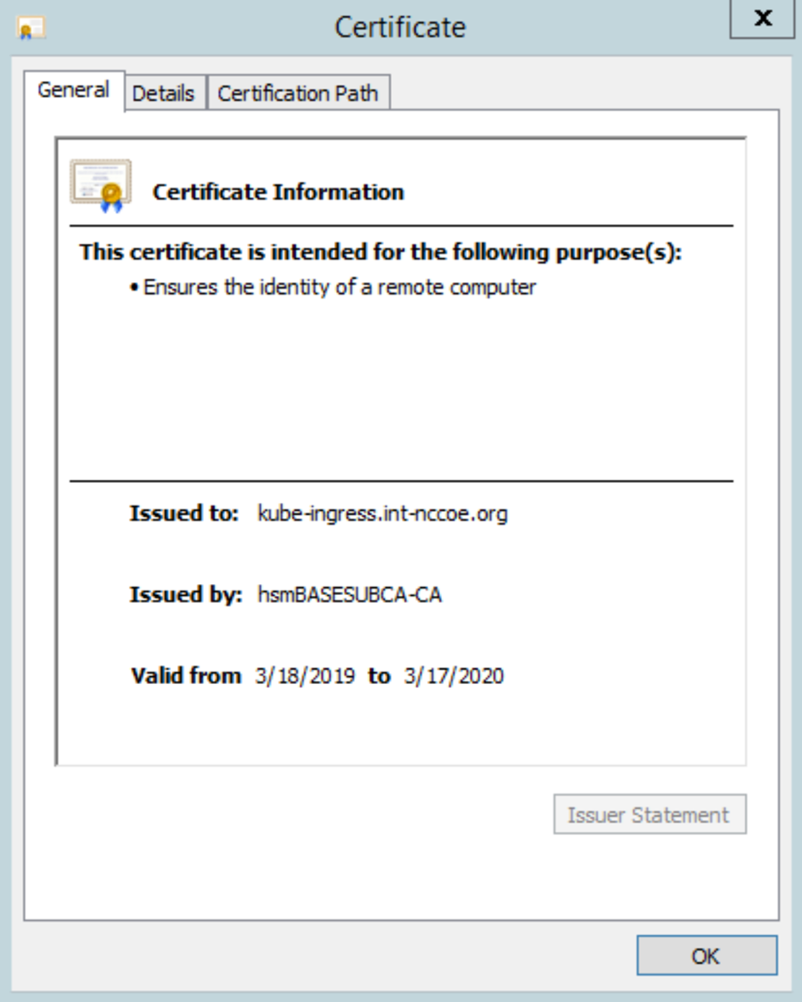
2.6.13.9 Symantec SSL Visibility
In our implementation, we configured Venafi TPP to automatically install TLS certificates and private keys used on several of the TLS servers—including IIS and Apache—onto the Symantec SSL Visibility to inspect traffic going to those servers.
Device object was created in Venafi TPP with the address and credentials for the Symantec SSL Visibility. For instructions on adding a device object, refer to the section titled “Adding Objects” in the Venafi Trust Protection Platform Administration Guide.
To ensure all required certificates and private keys are copied to the TLS inspection device, Venafi includes a feature called Bulk Provisioning. We created a bulk provisioning job.

We named the job to distinguish it from other bulk provisioning jobs.

We selected the device object created above for the Symantec SSL Visibility Appliance as the target to which private keys would be provisioned.
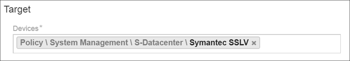
Venafi TPP was instructed to provision private keys associated with certificates in two folders:
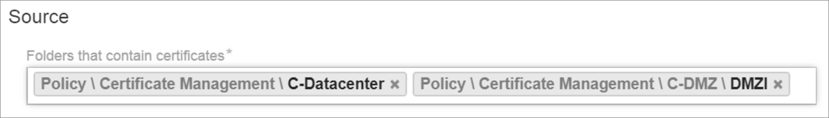
The default options excluded expired and revoked certificates and included historical certificates. Historical certificates are certificates that Venafi replaced by Venafi TPP. These certificates are still valid (not expired) and active on certain systems, though a new certificate was issued. Consequently, it is important to provision them to the TLS inspection appliance to ensure all traffic can be decrypted.

The bulk provisioning job was configured to run every Sunday at midnight to ensure new certificates and private keys are deployed to the TLS inspection device.
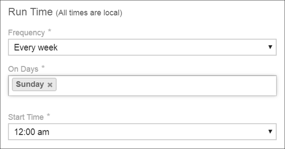
Venafi TPP uses an adaptable framework for bulk provisioning, so these jobs can be customized based on the environment’s requirements. To support bulk provisioning to the Symantec SSL Visibility, the bulk provisioning script has the Venafi TPP copied into the C:Program FilesVenafiScriptsAdaptableBulk directory. The bulk provisioning job was configured to use this script.
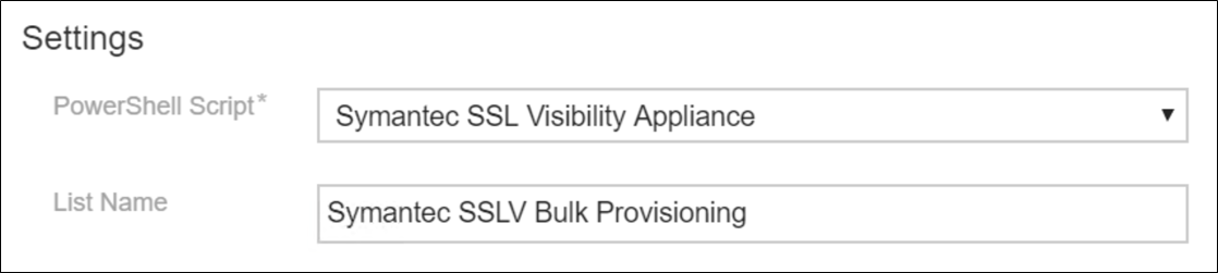
The bulk provisioning job will run once it is saved. The private keys were confirmed to be on the device.
To check if keys are saved in the SSL VISIBILITY, login to the SSL VISIBILITY WebUI by going to https://192.168.1.95
Go to PKI > Known Certificates and Keys.
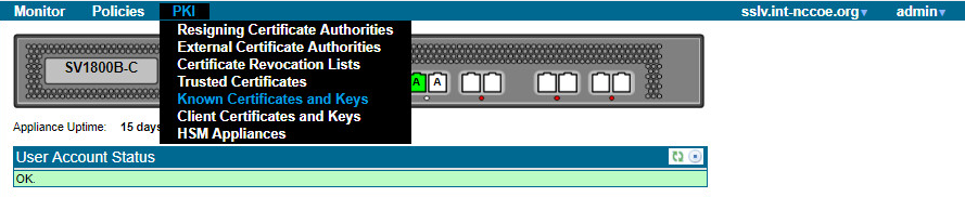
In the Known Certificates with Keys Lists field, click on the all-known-certificates-with-keys field.

The imported certificates and keys are then shown under the Known Certificate with Keys field.

2.6.14 Continuous Monitoring
Venafi TPP provides several tools that can continuously monitor TLS certificates within an enterprise, including scheduled network discovery scanning, monitoring certificates for expiration, and monitoring the operational status of known certificates.
2.6.14.1 Regular Network Scanning
In the lab, Venafi TPP was configured to perform weekly network discovery scans of the Datacenter and Datacenter Secure networks zones from the Venafi TPP server. The scans were scheduled to run at 2:00 a.m. each Sunday. The lab network was small enough for network scans to complete within a few minutes. Nonetheless, blackout periods were configured from 6:00 a.m. to 7:00 p.m. weekdays to ensure network scans were not performed during “normal business hours.”
A notification rule was defined to send an alert to the certificate services team upon discovery of either new certificates or previously unknown certificates (indicating they may have been issued and installed outside of standard processes) installations.
2.6.14.2 Certificate Expiration Monitoring
Significant application outages can occur when a certificate expires while in use. Consequently, it is critical that certificate owners track certificate expiration dates and replace them. The certificate services team can help certificate owners by implementing automated processes that monitor certificate expiration dates and notify the owners.
We used Venafi TPP in the lab to monitor certificate expiration dates and notify certificate owners. The methodology used in the lab followed the recommendations in SP 1800-16 Volume B. A weekly expiration report was scheduled giving certificate owners a list of certificates set to expire within the next 120 days. The following shows an example expiration report from the lab environment. The top of the report summarizes the status of certificates associated with a particular certificate owner.
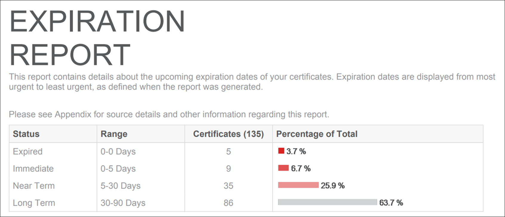
The expiration report lists all of the applicable certificates.
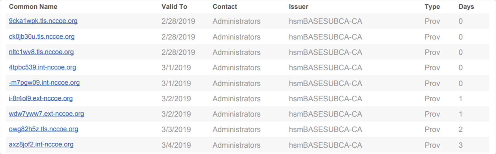
In addition to the reports, notification rules were configured to send emails to the owners of certificates expiring within 30 days. These notifications were configured to send daily, until the certificate was replaced. For any certificate expiring in less than 20 days, a notification rule was configured to send an additional email to escalation contacts, including the person identified as the Biz Owner and an incident response team. The objective was to minimize the amount of email that certificate owners received if all of their certificates were replaced in a timely fashion—ensuring sufficient alerts were sent for those certificates that still needed replacement.
2.6.14.3 Certificate Operation Monitoring
Network discovery scans provide insight into newly installed certificates, however, it’s equally important to monitor the operational state of known certificates. For example, a certificate owner may get a replacement certificate for an installed certificate set to expire. If the certificate isn’t installed prior to its expiration date, an outage can result. They may install the new certificate on several but not all of the systems where the existing certificate is installed, causing the systems that were not updated to fail when the existing certificate expires. Finally, they may install the new certificate in all necessary locations, but not reset the application so the new certificate is read and use by the application, resulting in an outage, because the application is continuing to use the existing certificate that expires.
Venafi TPP provides a service call network certificate validation that automatically checks deployed certificates to ensure the correct certificate is installed and operational, thereby addressing the issues described above. If a certificate issue is detected, the certificate owner is notified. Network certificate validation was enabled on Venafi TPP in the lab.
2.6.14.4 Logging of Certificate-related Security Events
Venafi TPP logs all management operations performed on certificates, including changes that administrators make within the user interfaces, changes via API, and all automated operations that are performed. Errors are also logged. All logged events are automatically stored in the Venafi TPP database. These events can be reviewed in the Venafi TPP console. It also is possible to sort, filter, and export the log events.
The following provides an example of several administrative events logged in our implementation, created by filtering on specific types of administrative events focused on configuration changes:
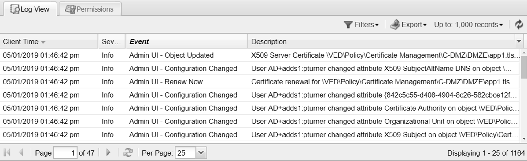
In addition to manually reviewing events within the console, it is possible to configure rules that will automatically send events. These events can be sent via a variety of different channels, including via email, to Splunk, to a syslog server, to an SNMP server, to a file, or to a database. Rules can be defined to send events based on specific criteria. For example, it is possible to send alerts prior to certificate expiration based on a configured set of days prior to expiration.
In our implementation, we configured Venafi TPP to send all events to the syslog server described in Section 1.5.5.6.
A syslog channel was created that pointed to the syslog server.

A rule was created to send a range of events from a severity of emergency to debug to the syslog channel.
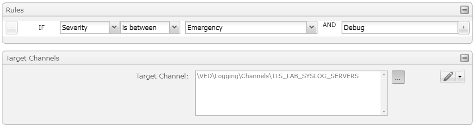
This approach to sending certificate-related events to an external security information and event management (SIEM) system enables all security-related events to be centralized and analyzed cohesively.