NIST SPECIAL PUBLICATION 1800-14B
Protecting the Integrity of Internet Routing:
Border Gateway Protocol (BGP) Route Origin Validation
Volume B:
Approach, Architecture, and Security Characteristics
William Haag
Applied Cybersecurity Division
Information Technology Laboratory
Doug Montgomery
Advanced Network Technologies Division
Information Technology Laboratory
Allen Tan
The MITRE Corporation
McLean, VA
William C. Barker
Dakota Consulting
Silver Spring, Maryland
June 2019
This publication is available free of charge from: https://doi.org/10.6028/NIST.SP.1800-14
The first draft of this publication is available free of charge from: https://www.nccoe.nist.gov/sites/default/files/library/sp1800/sidr-piir-nist-sp1800-14-draft.pdf

DISCLAIMER
Certain commercial entities, equipment, products, or materials may be identified by name or company logo or other insignia in order to acknowledge their participation in this collaboration or to describe an experimental procedure or concept adequately. Such identification is not intended to imply special status or relationship with NIST or recommendation or endorsement by NIST or NCCoE; neither is it intended to imply that the entities, equipment, products, or materials are necessarily the best available for the purpose.
National Institute of Standards and Technology Special Publication 1800-14B, Natl. Inst. Stand. Technol. Spec. Publ. 1800-14B, 173 pages, (June 2019), CODEN: NSPUE2
FEEDBACK
As a private-public partnership, we are always seeking feedback on our Practice Guides. We are particularly interested in seeing how businesses apply NCCoE reference designs in the real world. If you have implemented the reference design, or have questions about applying it in your environment, please email us at sidr-nccoe@nist.gov.
All comments are subject to release under the Freedom of Information Act (FOIA).
National Cybersecurity Center of Excellence
National Institute of Standards and Technology
100 Bureau Drive
Mailstop 2002
Gaithersburg, MD 20899
Email: nccoe@nist.gov
NATIONAL CYBERSECURITY CENTER OF EXCELLENCE
The National Cybersecurity Center of Excellence (NCCoE), a part of the National Institute of Standards and Technology (NIST), is a collaborative hub where industry organizations, government agencies, and academic institutions work together to address businesses’ most pressing cybersecurity issues. This public-private partnership enables the creation of practical cybersecurity solutions for specific industries, as well as for broad, cross-sector technology challenges. Through consortia under Cooperative Research and Development Agreements (CRADAs), including technology partners—from Fortune 50 market leaders to smaller companies specializing in IT security—the NCCoE applies standards and best practices to develop modular, easily adaptable example cybersecurity solutions using commercially available technology. The NCCoE documents these example solutions in the NIST Special Publication 1800 series, which maps capabilities to the NIST Cybersecurity Framework and details the steps needed for another entity to recreate the example solution. The NCCoE was established in 2012 by NIST in partnership with the State of Maryland and Montgomery County, Md.
To learn more about the NCCoE, visit https://www.nccoe.nist.gov/. To learn more about NIST, visit https://www.nist.gov.
NIST CYBERSECURITY PRACTICE GUIDES
NIST Cybersecurity Practice Guides (Special Publication Series 1800) target specific cybersecurity challenges in the public and private sectors. They are practical, user-friendly guides that facilitate the adoption of standards-based approaches to cybersecurity. They show members of the information security community how to implement example solutions that help them align more easily with relevant standards and best practices, and provide users with the materials lists, configuration files, and other information they need to implement a similar approach.
The documents in this series describe example implementations of cybersecurity practices that businesses and other organizations may voluntarily adopt. These documents do not describe regulations or mandatory practices, nor do they carry statutory authority.
ABSTRACT
The Border Gateway Protocol (BGP) is the default routing protocol to route traffic among internet domains. While BGP performs adequately in identifying viable paths that reflect local routing policies and preferences to destinations, the lack of built-in security allows the protocol to be exploited by route hijacking. Route hijacking occurs when an entity accidentally or maliciously alters an intended route. Such attacks can (1) deny access to internet services, (2) detour internet traffic to permit eavesdropping and to facilitate on-path attacks on endpoints (sites), (3) misdeliver internet network traffic to malicious endpoints, (4) undermine Internet Protocol (IP)-address-based reputation and filtering systems, and (5) cause routing instability in the internet. This document describes a security platform that demonstrates how to improve the security of inter-domain routing traffic exchange. The platform provides route origin validation (ROV) by using the Resource Public Key Infrastructure (RPKI) in a manner that mitigates some misconfigurations and malicious attacks associated with route hijacking. The example solutions and architectures presented here are based upon standards-based, open-source, and commercially available products.
KEYWORDS
AS, autonomous systems, BGP, Border Gateway Protocol, DDoS, denial-of-service (DoS) attacks, internet service provider, ISP, Regional Internet Registry, Resource Public Key Infrastructure, RIR, ROA, route hijack, route origin authorization, route origin validation, routing domain, ROV, RPKI
ACKNOWLEDGMENTS
We are grateful to the following individuals for their generous contributions of expertise and time.
| Name | Organization |
|---|---|
| Tim Battles | AT&T |
| Jay Borkenhagen | AT&T |
| Chris Boyer | AT&T |
| Nimrod Levy | AT&T |
| Kathryn Condello | CenturyLink |
| Christopher Garner | CenturyLink |
| Peter Romness | Cisco Systems |
| Tony Tauber | Comcast |
| Jonathan Morgan | Juniper Networks |
| Carter Wyant | Juniper Networks |
| Oliver Borchert | NIST ITL Advanced Networks Technologies Division |
| Kotikalapudi Sriram | NIST ITL Advanced Networks Technologies Division |
| Sean Morgan | Palo Alto Networks |
| Tom Van Meter | Palo Alto Networks |
| Andrew Gallo | The George Washington University |
| Sophia Applebaum | The MITRE Corporation |
| Yemi Fashina | The MITRE Corporation |
| Susan Prince | The MITRE Corporation |
| Susan Symington | The MITRE Corporation |
The Technology Partners/Collaborators who participated in this build submitted their capabilities in response to a notice in the Federal Register. Respondents with relevant capabilities or product components were invited to sign a Cooperative Research and Development Agreement (CRADA) with NIST, allowing them to participate in a consortium to build this example solution. We worked with:
| Technology Partner/Collaborator | Build Involvement |
|---|---|
| AT&T | Subject Matter Expertise |
| CenturyLink | 1 gigabit per second (Gbps) Ethernet Link Subject Matter Expertise |
| Cisco | 7206 VXR Router v15.2 ISR 4331 Router v16.3 2921 Router v15.2 IOS XRv 9000 Router v6.4.1 Subject Matter Expertise |
| Comcast | Subject Matter Expertise |
| Juniper Networks | MX80 3D Universal Edge Router v15.1R6.7 Subject Matter Expertise |
| Palo Alto Networks | Palo Alto Networks Next-Generation Firewall PA-5060 v7.1.10 Subject Matter Expertise |
| The George Washington University | Subject Matter Expertise |
List of Figures
Figure 5-1 The ROV Portion of the RPKI-Based ROV Reference Architecture
Figure 5-2 The Hosted-Model RPKI Reference Architecture
Figure 5-3 The Delegated-Model RPKI Reference Architecture
Figure 5-4 Example ROV and RPKI Reference Architectures
Figure 5-5 Route Origin Validation Usage Scenario
Figure 5-6 Delegated-Model RPKI Usage Scenario
Figure 5-7 SIDR Lab Physical Architecture
Figure 7-1 SIDR Testbed Using the Test Harness
Figure 7-2 SIDR Testbed Using Live Traffic
Figure E-1 SIDR Testbed Using the Test Harness
Figure E-2 SIDR Testbed Using Live Traffic
List of Tables
Table 4-2 Products and Technologies
Table E-1 SIDR Functional Requirements
1. Summary
This National Institute of Standards and Technology (NIST) Cybersecurity Practice Guide addresses the challenge of using existing protocols to improve the security of inter-domain routing traffic exchange in a manner that mitigates accidental and malicious attacks associated with route hijacking.
A route prefix hijack occurs when an autonomous system (AS) accidentally or maliciously originates a Border Gateway Protocol (BGP) update for a route prefix that it is not authorized to originate. For example, a BGP update for Internet Protocol (IP) prefix 192.0.2.0/24 might legitimately be originated by one AS, but a different AS might fraudulently originate a BGP route update for that prefix. Many ASes for which the illegitimate AS is closer (i.e., in terms of a shorter routing path length) would trust the false update, and thus data traffic from them toward the said prefix would be misrouted to the illegitimate AS. The path to the prefix via the false origin AS will be shorter, on average, for about half of all ASes in the internet. So, nearly half of the internet ASes would install the false route in their Forwarding Information Base (FIB).
When an offending AS fraudulently announces a more specific prefix than the prefix announced legitimately by another AS, practically all of the internet ASes would install the false route in their FIB.
This Practice Guide implements and follows various Internet Engineering Task Force (IETF) Request for Comments (RFC) documents that define Resource Public Key Infrastructure (RPKI)-based BGP route origin validation (ROV), such as [RFC_6480], [RFC_6482], [RFC_6811], and [RFC_7115], as well as recommendations of [NIST_SP_800-54], Border Gateway Security. To the extent practicable from a system composition point of view, the security platform design, build, and test processes have followed [NIST SP 800-160]_, Systems Security Engineering: Considerations for a Multidisciplinary Approach in the Engineering of Trustworthy Secure Systems.
The NIST Special Publication (SP) 1800-14 series of documents consists of the following volumes:
- Volume A: an executive-level summary describing the challenge that RPKI-based ROV is designed to address, the ROV solution, and its benefits
- Volume B: a rationale for, and descriptions of, RPKI-based internet routing platforms that perform BGP-based ROV
- Volume C: a series of How-To Guides, including instructions for the installation and configuration of the necessary services, that show system administrators and security engineers how to achieve similar outcomes
The solutions and architectures presented are built upon standards-based, commercially available, and open-source products. These solutions can be used by any organization providing or using internet routing services that is willing to perform the steps necessary to perform and/or benefit from RPKI-based ROV. Interoperable solutions are provided that are available from different types of sources (e.g., both commercial and open-source products).
This summary section (Section 1) describes the challenge addressed by Volume B (Approach, Architecture, and Security Characteristics), the solution demonstrated to address the challenge, and the benefits of the demonstrated solution. Section 2, How to Use This Guide, explains how each volume of this guide may be used by business decision makers, program managers, and information technology (IT) professionals, such as systems administrators. Section 3, Background, provides a high-level project overview. Section 4, Approach, provides a more detailed treatment of the project’s intended audience, scope, assumptions, and the risks that informed it. Section 4 also describes the technologies and components that were provided by industry collaborators to enable platform development, and lists the Cybersecurity Framework Functions supported by each collaborator-contributed component. For each security characteristic supported, it lists not only the Cybersecurity Framework Categories and Subcategories, but also the Security and Privacy Controls for Information Systems and Organizations [NIST SP 800-53]_ controls and additional references, standards, and guidelines that apply to each security function being demonstrated. Section 5, Architecture, describes the RPKI-based ROV reference architecture and the usage scenarios that it supports, as well as the architecture of the laboratory-based solution that was implemented at the National Cybersecurity Center of Excellence (NCCoE). Section 6, Outcome, discusses lessons learned, best practices, and other items relevant to systems administrators’ experiences with respect to integrating the new capabilities into their systems and in systems operations and maintenance. Section 7, Functional and Robustness Results, summarizes the tests that were performed to demonstrate security platform functionality and provides an overview of platform performance in the scenarios demonstrated. Section 8, Recommendations for Follow-on Activities, provides a brief description of future work that could be pursued to promote the adoption of Border Gateway Protocol Security (BGPsec) [RFC_8205] to provide protection for the path information in BGP updates. Appendices are provided for a description of the use of [NIST_SP_800-160] in project design and development; recommended education and training requirements for internet service provider (ISP) operators and enterprises; further discussion of the mapping of the secure inter-domain routing (SIDR) security platform to the Cybersecurity Framework Core; informative security references cited in the Cybersecurity Framework Core; further discussion of assumptions; functional test requirements; results; acronyms; and references.
1.1. Challenge
Attacks against the internet routing functions are probably one of the greatest current threats to today’s internet. Routing attacks can have regional, or even global, impact. There have been numerous incidents in recent years involving control plane anomalies, such as route hijacking, AS path modification attacks (e.g., an AS in the middle maliciously shortens a path to attract more traffic), route leaks, spoofing source addresses, etc., resulting in Denial-of-Service (DoS), unwanted data traffic detours, and performance degradation that is sufficiently severe to seriously disrupt the internet on a very large scale and for periods that can seriously harm organizations, the economy, and national security.
Protocols have been defined that are designed to provide protection against many of the routing attacks mentioned above. The technique that is the subject of this practice guide, RPKI-based ROV, enables operators to verify that the AS that has originated a BGP route advertisement is, in fact, authorized to do so. The use of RPKI-based ROV can provide protection against accidental, and some malicious, route hijacks. A second protocol, BGPsec, allows network operators to verify the validity of the entire routing path across the internet (referred to as path validation). The use of RPKI-based ROV in conjunction with BGPsec can provide protection against malicious route hijacks as well as other routing attacks. Unfortunately, the adoption of both ROV and BGPsec is still very limited. In the case of BGPsec, while the specification of the BGPsec-based path validation is complete [RFC_8205], [RFC_8207], [RFC_8208], [RFC_8210], and open-source implementations [NIST_BGP-SRx], [Parsons_BGPSec] are available, there is still a lack of commercial implementations available from router vendors.
BGPsec also has several other obstacles impeding its deployment, as compared with ROV, such as the fact that support for it will be resource-intensive because it increases the size and number of routing messages that are sent, and each message will require a cryptographic verification of at least one, and most likely multiple, digital signatures. Digital signature verification will be processing-intensive and may require hardware upgrades and/or software optimizations [NANOG69] [V_Sriram]. It also adds a level of complexity with respect to the acquisition and management of public keys for BGP routers, as well as the X.509 certificates used in sharing those keys.
Although the BGP path validation protections of BGPsec have not yet been incorporated into most vendor equipment, the state of implementation of BGP ROV, on the other hand, is more advanced. ROV capabilities have already been incorporated into the equipment of major vendors (e.g., they ship with Cisco, Juniper, and Alcatel/Lucent/Nokia routers). Further RPKI operations and repositories at all five Regional Internet Registries (RIRs) are in production. In some regions of the world, RIRs provide tools and support that facilitate an efficient implementation of RPKI-based ROV. However, commercial adoption to date has been slow, particularly in the North American region. This situation is beginning to change in other regions of the world. As of this writing, Europe, in particular, is approaching route origin authorization (ROA) coverage of approximately 43 percent of their announced Internet Protocol Version 4 (IPv4) address space, due, in part, to forward-looking adoption policies and favorable and flexible usage polices for RPKI services. North America trails Europe, Latin and South America, and Africa in its rate of adoption, with only approximately seven percent of its announced IPv4 address space covered by ROAs.
1.2. Solution
This Practice Guide (NIST SP 1800-14) describes how to use available security protocols, products, and tools to provide RPKI-based ROV in enterprises. This Practice Guide focuses on a proof-of-concept implementation of the IETF security protocols and the NIST implementation guidance needed to protect ISPs and ASes against the consequences of widespread and localized route hijacking attacks. Although it would have been preferable to protect against additional types of routing attacks by also focusing on the more comprehensive solution of BGP path validation in conjunction with ROV, the lack of commercial vendor implementation support for BGPsec makes providing a BGP path validation solution impractical at this time. Hence, this Practice Guide is focusing only on providing ROV.
The proof-of-concept implementation is used to demonstrate BGP ROV, using RPKI, to address and resolve route hijacking issues. The demonstration shows how, by using ROV, an AS can protect routes that it originates and flag and discard (or apply some other policy to, as desired) bogus routes that it receives that do not come from ASes that are authorized to originate the routes. The proof-of-concept implementation demonstrates RPKI-based ROV in realistic deployment scenarios. Also, some additional functionality, performance, robustness, and availability tests suggested by industry collaborators on the team were performed.
This Practice Guide offers detailed deployment guidance, identifies implementation and use issues, and generates best practices and lessons learned. Volume C of this Practice Guide serves as a detailed implementation guide to the practical steps required to implement a cybersecurity reference design that mitigates the inter-domain routing security challenge.
1.3. Benefits
The ROV capabilities demonstrated by the proof-of-concept implementation described in this Practice Guide improve inter-domain routing security by using standards-conformant security protocols to enable an entity that receives a BGP route update to validate whether the AS that has originated it is, in fact, authorized to do so. The capability demonstrated by the proof-of-concept can facilitate the adoption of ROV by ASes by making it easier for entities to use the RPKI to create and validate objects that explicitly and verifiably assert that an AS is authorized to originate routes to a given set of prefixes. The creation of ROAs can be accomplished independently by each address resource holder, and ROV can be deployed by each AS independently. Thus, there is clearly a benefit for early adopters, and deployment grows in a distributed manner. All organizations and individuals who are dependent on the internet stand to benefit greatly from the improvement to the security and stability of the global internet that can be achieved by providing a level of assurance that routing assertions come from the sources that are authorized to originate them. In particular, entities that issue ROA for the prefixes that they hold will benefit from the assurance that accidental hijackings and some malicious hijackings are prevented.
2. How to Use This Guide
This NIST Cybersecurity Practice Guide demonstrates a standards-based reference design and provides users with the information they need to replicate this approach to inter-domain routing security. This reference design is modular and can be deployed in whole or in part.
This guide contains three volumes:
- NIST SP 1800-14A: Executive Summary
- NIST SP 1800-14B: Approach, Architecture, and Security Characteristics — what we built and why (you are here)
- NIST SP 1800-14C: How-To Guides — instructions for building the example solution
Depending on your role in your organization, you might use this guide in different ways:
Business decision makers, including chief security and technology officers, will be interested in the Executive Summary, NIST SP 1800-14A, which describes the following topics:
- challenges that enterprises face in implementing and maintaining ROV
- an example solution built at the NCCoE
- the benefits of adopting the example solution.
Technology or security program managers who are concerned with how to identify, understand, assess, and mitigate risk will be interested in this part of the guide, NIST SP 1800-14B, which describes what we did and why. Section 4.4, Risk Assessment, will be of particular interest. This section provides a description of the risk analysis we performed and maps the security services provided by this example solution to NIST’s Framework for Improving Critical Infrastructure Cybersecurity and to relevant security standards and guidelines.
You might share the Executive Summary, NIST SP 1800-14A, with your leadership team members to help them understand the importance of adopting standards-based ROV approaches to protect your organization’s digital assets.
IT professionals who want to implement an approach like this will find the whole practice guide useful. You can use the How-To portion of the guide, NIST SP 1800-14C, to replicate all or parts of the build created in our lab. The How-To portion of the guide provides specific installation, configuration, and integration instructions for implementing the example solution. We do not recreate the product manufacturers’ documentation, which is generally widely available. Rather, we show how we incorporated the products together in our environment to create an example solution.
This guide assumes that IT professionals have experience in implementing security products within the enterprise. While we have used a suite of commercially available and open-source software products to address this challenge, this guide does not endorse these particular products. Your organization can adopt this solution or one that adheres to these guidelines in whole, or you can use this guide as a starting point for tailoring and implementing parts of a solution that would support the deployment of an ROV-RPKI system and the corresponding business processes. Your organization’s security experts should identify the products that will best integrate with your existing tools and IT system infrastructure. We hope that you will seek products that are congruent with applicable standards and best practices. Section 4.5, Technologies, lists the products we used and maps them to the cybersecurity Functions called out in the Cybersecurity Framework.
2.1. Typographic Conventions
The following table presents typographic conventions used in this volume.
| Typeface/Symbol | Meaning | Example | |
|---|---|---|---|
| Italics | filenames and pathnames, references to documents that are not hyperlinks, new terms, and placeholders | For detailed definitions of terms, see the NCCoE Glossary. | |
| Bold | names of menus, options, command buttons and fields | Choose File > Edit. | |
Monospace
|
command-line input, on-screen computer output, sample code examples, status codes | mkdir
|
|
Monospace Bold
|
command-line user input contrasted with computer output | service sshd start
|
|
| blue text | link to other parts of the document, a web URL, or an email address | All publications from NIST’s National Cybersecurity Center of Excellence are available at https://www.nccoe.nist.gov. | |
3. Background
Most of the routing infrastructure underpinning the internet currently lacks basic security services. In most cases, internet traffic must transit multiple ISPs before reaching its destination. Each network operator implicitly trusts other ISPs to provide (via BGP) the accurate information necessary for network traffic to be routed correctly. When that information is inaccurate, traffic will take inefficient paths through the internet, arrive at malicious sites that masquerade as legitimate destinations, or never arrive at its intended destination. The consequences of these attacks can (1) deny access to internet services; (2) detour internet traffic to permit eavesdropping and to facilitate on-path attacks on endpoints (sites); (3) misdeliver internet network traffic to malicious endpoints, thereby providing the technical underpinning for other forms of cyber attack; (4) undermine IP-address-based reputation and filtering systems; and (5) cause routing instability in the internet. These impacts can be mitigated through the widespread adoption of current and emerging internet routing security protocols.
On April 8, 2010, nearly 15 percent of the world’s internet traffic—including data from the United States (U.S.) Department of Defense and other U.S. government internet services—was redirected through computer networks in China [N_Anderson]. Between February and May 2014, network traffic from 51 networks from 19 different ISPs was repeatedly hijacked in carefully crafted attacks aimed at stealing cryptocurrency [A_Greenberg]. In June 2015, a third-party ISP in Asia asserted that it was the most efficient route to the entire internet, disrupting traffic worldwide and resulting in customers experiencing severe network problems [Saarinen]. In February 2008, YouTube became unreachable from most, if not all, of the internet. In an attempt to block access to a video that the Pakistani government considered blasphemous, Pakistan Telecom inadvertently redirected YouTube’s traffic worldwide to an alternative site [Singel]. While, to date, the impacts of these events range from a loss of access to social media to potential issues of national and economic security, they share a root cause: the internet’s routing infrastructure currently relies on protocols that lack basic security services.
This lack of security in the internet’s routing infrastructure could be mitigated through the widespread adoption of current and emerging internet security protocols. The IETF, with significant contributions from the Department of Homeland Security and NIST, has developed standards and protocols to secure global internet routing. For example, the IETF has defined the RPKI, which is designed to secure the internet’s routing infrastructure. The RPKI enables an enterprise to prove that it holds a range of internet addresses and to identify the ASes that the holder authorizes to originate routes to its addresses by using cryptographically verifiable ROAs. RPKI services are available today from the RIRs, which manage the allocation and registration of internet resources. Commercial routers are available today that are capable of using RPKI data to identify accidental errors in routing announcements by determining that the origin AS in the route contradicts an existing ROA in the RPKI.
ROV provides good protection against the accidental mis-origination of routes, but not necessarily against the intentional (e.g., malicious) mis-origination of routes. If an attacker adds the autonomous system number (ASN) (of the AS that is authorized to originate a route) to the beginning of the AS path in a bogus BGP route update in order to forge the origin AS in that update, then the bogus route update will pass ROV and will not be detected as bogus even though it is, because ROV assumes that the AS path is correct, rather than providing any sort of integrity checking on the AS path.
A separate protocol, BGPsec, augments RPKI-based ROV to detect these types of malicious route announcements by enabling network operators to verify the validity of the entire routing path across the internet (referred to as path validation), as opposed to just validating the authority of the originating AS. If widely implemented together, ROV and BGPsec would significantly improve the security and stability of global internet routing.
Unfortunately, the adoption of ROV and BGPsec security protocols has been slow due to impediments, such as usability, performance, and cost:
- Usability: Internet routing security mechanisms are implemented primarily by ISPs and ASes. As such, the usability impacts are felt mostly by systems administrators for those services. ISP and AS administrators are faced with relatively few application choices, immature documentation, relatively immature products, and relatively complex installation and configuration processes. Furthermore, adding more data, data sources, and maintainers to the BGP decision and policy frameworks imparts several new failure modes. Thus, an already complex troubleshooting landscape can get significantly more complex.
- Performance: Some increase in processing latency may occur due to the processing associated with routing security protocols. With the use of RPKI to address ROV and the addition of an RPKI cache(s), new router operating systems (OSes) may have performance implications. A more significant performance issue is that longer paths to destinations are used due to fewer routing path choices from improper configuration. BGPsec path validation introduces a different set of performance issues. The reduction in available paths would be due to ISP/AS interdependencies that exacerbate the effects of connection refusals due to path validation failures in a path when an ISP/AS has not implemented the required integrity verification functionality. As in the case of Domain Name System Security, many of the connection refusals may be due to certificate management difficulties. The BPGsec protocol to be used for path validation is expected to be resource intensive. Each BGP update will have one or more digital signatures in it, thereby increasing the size of the message. Every one of the AS hops in the AS path will have an associated digital signature that must be verified. Also, each update will be able to carry only a single prefix, so updates will be more numerous.
- Cost: Much of the cost associated with the implementation of ROV using RPKI involves an integration of the few, and still relatively immature, products into existing systems that have an installed applications base, complete with restrictive support agreements. For example, some vendors prohibit the installation of software other than that distributed by themselves. Immature documentation and relatively complex installation and configuration processes add to this labor cost impact. Support contract impacts also represent a very significant cost-based impediment to ROV implementation at this time. If equipment needs to be upgraded, then its support contract may need to be updated or revised. The cost of implementing BGPsec in the future may be significantly larger than RPKI-based ROV. Because ISPs and ASes will need to support an additional type of certificate that binds their ASN to a public key, additional provisions for RPKI and router processing resources (upgraded hardware and router memory) will be needed to support path validation.
Other impediments to adoption include needed security features not being available from a vendor with which significant user sets have restrictive support contracts; incompatibility with potential users’ installed bases; uncertainties associated with installation, integration, and activation processes; support concerns on the part of potential users who rely on software that is subject to frequent updates; resistance to making changes that might change the user experience (regardless of user-experience improvements that may accrue); and simply not being on the potential user’s already-approved long-term system development, upgrade, and support plans (road maps).
The relative immaturity of available components and the lack of ubiquitous support for those components are also impediments to the implementation of route origin and path validation protocols.
Additional labor and support contract costs from equipment upgrades can result in competitive disadvantages. At least at first, mandating ROV can result in reduced routing path options (especially in the face of ISP/AS interdependencies), fewer partner relationship options, and fewer service delivery options.
Although the adoption of both ROV and BGPsec may have been hindered for the reasons mentioned above, the adoption and deployment of BGPsec is expected to be even slower relative to that of ROV. Commercial BGPsec implementations are not currently available. Also, the use of digital signatures in BGPsec adds a level of complexity with respect to the acquisition and management of router public keys, as well as the X.509 certificates used in sharing those keys. The relative scarcity of key management tools means that implementing organizations spend significant expert labor resources on complex cryptographic key-related acquisition, installation, configuration, and management.
ROV, on the other hand, has already been incorporated into the equipment of major vendors (i.e., it ships with Cisco, Juniper, and Alcatel/Lucent/Nokia routers), and all RIRs are in production mode with RPKI services. Furthermore, in some regions of the world, RIRs provide tools and support that facilitate the efficient implementation of these protocols. ROV adoption is sluggish in North America, where demand is insufficient to motivate the adoption of RPKI on a large scale. Customers do not demand ROV from their own network providers because the primary benefit would be to customers of other networks. Network providers are hesitant to invest in routing security because their customers do not demand it. Numerous governmental and industry road maps (e.g., Federal Communications Commission Communications Security, Reliability and Interoperability Council III Working Groups 4 and 6 reports) do call for the incremental deployment of new BGP security technologies. However, market pressure has been insufficient to overcome implementation constraints, and commercial adoption to date has been slow.
As previously mentioned, this situation is beginning to change in other regions of the world. Europe, in particular, is approaching an ROA coverage of approximately 43 percent of its announced IPv4 address space, due, in part, to forward-looking adoption policies and favorable and flexible usage polices for RPKI services. North America trails Europe, Latin and South America, and Africa in its rate of adoption, with only approximately seven percent of its announced IPv4 address space covered by ROA.
Given the lack of commercial vendor implementation support for BGPsec, other obstacles currently hindering its adoption, and the more favorable position of ROV with respect to being standardized and incorporated into vendor equipment, this effort is initially focusing only on BGP ROV.
The proof-of-concept implementation described in this Practice Guide demonstrates the use of available hardware and software to mitigate impediments to the adoption of ROV protocols. It takes advantage of available tools to facilitate implementation, operation, and maintenance; to improve the performance of administration functions; and to reduce the labor requirements that are major contributors to implementation costs. It is anticipated that a successful demonstration of currently available products and tools that mitigate the impediments preventing individual institutions from implementing ROV will foster the increased implementation of routing security protocols to the point that interoperability considerations will favor global implementation.
For hosted RPKI, an RIR provides the infrastructure to host the certificate authorities (CAs) and private keys used to sign the ROAs for address blocks registered in the RIR’s region. An ROA authorizes one or more route prefixes to be originated from an AS and is signed with the private key associated with the prefix holder’s digital end-entity (EE) certificate. The ROA also specifies a maximum prefix length (maxLength) [RFC_6482] so that an announcement of prefixes longer than the maxLength would be invalid. Address holders who are registered with the RIR and have received address allocations from it can access tools provided by the RIR to create and publish ROAs for those addresses. Those ROAs are stored in the RIR’s RPKI repositories. Network operators around the world can retrieve the ROAs from the RIR RPKI repositories, validate their integrity and authenticity, and use the information in the ROAs to detect the validity of the origin AS in the received BGP updates. Depending on the ISP’s or AS’s policy, routes (i.e., updates) that fail ROV may be assigned a lower priority in the route selection or may be discarded. A failed ROV indicates that the ROV evaluation process determines the route to be invalid. For delegated RPKI, address holders (e.g., ISPs, large enterprises) operate a delegated RPKI CA and their own publication point to store associated certificates, keys, and ROAs. This implementation model allows an ISP or other entity to offer hosted or delegated RPKI resources to its customers. This project focused on both the hosted RPKI model and the delegated RPKI model.
4. Approach
4.1. Audience
This guide is intended for individuals responsible for implementing security solutions in organizations’ IT support activities. The information provided in this Practice Guide permits the integration of ROV with minimum changes to the existing infrastructure and with minimum impact to service operations. The technical components will appeal to system administrators, IT managers, IT security managers, and others directly involved in the secure and safe operation of the business IT networks.
4.2. Scope
The scope of this project covers the roles of both address holders and network operators. Address holders are responsible for creating RPKI content, such as ROAs, that can be used to validate that specific ASes are authorized to originate routes to the addresses that they hold. Network operators are responsible for providing BGP-based routing services to clients and their peer networks in other ASes, and use the ROAs and other RPKI content to perform ROV. Note that the same entity may be both an address holder and a network operator.
For address holders, the scope of this project includes the demonstration of two implementation models of RPKI: hosted RPKI and delegated RPKI.
A determination of the vulnerability of the RPKI repository to intrusion and malicious alterations of data was outside the scope of the project. The project included partners and Community of Interest (COI) collaborators from various classes of enterprises, and service providers that contributed to the design and conduct of tests in these areas.
For network operators, the scope of the project focused on the deployment of, and scenarios for the use of, RPKI-ROA information in support of BGP ROV [RFC_6811]. The project tested the functionality of RPKI/ROV components and documented issues and best practices for the operation and use of RPKI validating caches (VCs) and ROV-capable BGP routers. It addressed issues about the robustness and responsiveness of these components, as well as routing policies that can be configured for them. The project included COI and National Cybersecurity Excellence Partnership (NCEP) partners to provide commercial off-the-shelf (COTS) and open-source products that implement the components necessary for BGP network operators to acquire, validate, and use RPKI information to implement BGP ROV. The project also included COI collaborators from various classes of network operators (e.g., enterprise, stub ISPs, regional networks, transit ISPs, internet exchange point operators) that contributed to the design and conduct of tests in realistic scenarios (e.g., BGP routing architectures, exterior border gateway protocol [eBGP] and interior border gateway protocol [iBGP], ISP architectures).
For each deployment scenario, RPKI-based ROV functionality was validated, including various scenarios for BGP ROV results (valid, invalid, and not found [RFC_6811]) and vendor implementation-specific options for RPKI-ROV-based filtering mechanisms. This project has resulted in this freely available NIST Cybersecurity Practice Guide describing steps to demonstrate, deploy, and manage RPKI-based ROV for both enterprises and network operators; identify implementation and interoperability issues; provide sample deployment architectures; and provide lessons learned from employing controls identified in [NIST_SP_800-53].
The IETF has also developed a new protocol called BGPsec, which provides cryptographic protection for the entire AS path in a BGP update. This security extension to BGP would help prevent AS path modification attacks (e.g., maliciously shortening the AS path to redirect traffic). However, commercial router implementations of BGPsec are not currently available. Hence, this effort initially focuses on BGP ROV, and consideration of the BGPsec protocol is currently outside the scope of this project.
4.3. Assumptions
This project assumes that most potential adopters of the demonstrated build or any build components do not already have RPKI-based ROV tools or mechanisms in place, but that they do already have routing systems. This Practice Guide is intended to provide installation, configuration, and integration guidance, and assumes that an organization has the technical resources to implement all or parts of the build or has access to companies that can perform the implementation on its behalf. The guidance provided in this document may be used to provide a complete top-to-bottom solution or may be applied in a modular fashion to provide selected options based on need. It is intended that the benefits of adopting RPKI-based ROV outweigh any additional performance, reliability, or security risks that may be introduced by instantiating the protocols.
RIRs play vital roles in RPKI, both in terms of assisting with the creation of RPKI content by address holders and in terms of making that content available to relying parties (RPs) via repositories that are hosted online. It is assumed that address holders understand the usage of RPKI resources. When using the hosted model, address holders must have agreements in place with an RIR or other hosting authority that enables the address holder to request that the host create, sign, and store ROAs for the address holders’ addresses. When using the delegated model, the address holder must provide and manage its own RPKI infrastructure and CA to create, sign, store, and manage its own ROAs, rather than rely on a host to provide this infrastructure and services. For organizations that choose to use the delegated model and run their own CA, there is open-source software available to create the RPKI infrastructure and securely communicate with the RIR parent system. Network operators who provide BGP-based routing services are responsible for operating RPKI VCs and ROV-capable routers so that they can retrieve ROA information from RPKI repositories and can use it to perform ROV on BGP updates that they receive.
When a router applies ROV to a received BGP update, the router determines whether the update is valid, invalid, or not found. Based on this information, organizations can apply policies to the routes. Valid routes should typically be installed into the routing table, but what a router does with invalid and not found routes is the prerogative of the organization that operates the router, and will depend on local policy. Service provider policies may take into account whether there are requirements to forward routes to customers as well as local considerations. Enterprise policies will depend on enterprise-specific considerations. This project does not attempt to dictate the policies that any organization should implement. As a first step toward adoption, enterprises could simply perform ROV and mark all routes as valid, invalid, or not found. No further policy is needed beyond simply observing the number of routes that are invalid or not found.
4.4. Risk Assessment
While this guide does not present a full risk assessment as discussed in [NIST_SP_800-30] or [NIST_SP_800-37], it does describe the risks associated with unauthorized updates to routing information and identify some route hijacking risks that may be addressed in follow-on project activities.
[NIST_SP_800-30], Guide for Conducting Risk Assessments, states that risk is “a measure of the extent to which an entity is threatened by a potential circumstance or event, and typically a function of (i) the adverse impacts that would arise if the circumstance or event occurs and (ii) the likelihood of occurrence.” The guide further defines risk assessment as “the process of identifying, estimating, and prioritizing risks to organizational operations (including mission, functions, image, and reputation), organizational assets, individuals, other organizations, and the Nation, resulting from the operation of an information system. Part of risk management incorporates threat and vulnerability analyses, and considers the mitigations provided by planned or in-place security controls.”
The NCCoE recommends that any discussion of risk management, particularly at the enterprise level, begins with a comprehensive review of [NIST_SP_800-37], Guide for Applying the Risk Management Framework to Federal Information Systems —material that is available to the public. The Risk Management Framework (RMF) guidance, as a whole, proved to be invaluable in giving us a baseline to assess risks, from which we developed the project, the security characteristics of the build, and this guide.
4.4.1. Threats
The IETF’s Threat Model for BGP Path Security [RFC_7132] points out that BGP routers themselves can inject bogus routing information either by masquerading as any other legitimate BGP router or by distributing unauthorized routing information as themselves. Historically, misconfigured and faulty routers have been responsible for widespread disruptions in the internet. As stated in [RFC_4593], legitimate BGP peers have the context and information to produce believable, yet bogus, routing information, and therefore have the opportunity to cause great damage. Cryptographic protections and operational protections cannot necessarily exclude the bogus information arising from a legitimate peer.
Threats to routing include deliberate exposure, sniffing, traffic analysis, spoofing, false route origination, interference, secure path downgrade, and overload. Of these, spoofing and false origination are most relevant to this project.
Spoofing: occurs when an illegitimate device assumes the identity of a legitimate one. Spoofing, in and of itself, is often not the true attack. Spoofing is special, in that an attacker can use it as a means for launching other types of attacks. For example, if an attacker succeeds in spoofing the identity of a router, then the attacker can send out unrealistic routing information that might cause the disruption of network services. There are a few cases where spoofing can be an attack in and of itself. For example, messages from an attacker that spoof the identity of a legitimate router may cause a neighbor relationship to form and deny the formation of the relationship with the legitimate router. The primary consequence is that the authorized routers, which exchange routing messages with the spoofing router, do not realize that they are neighboring with a router that is faking another routerʼs identity. Another consequence includes the spoofing router gaining access to the routing information.
False route origination: occurs when an attacker sends false routing information. To falsify the routing information, an attacker has to be either the originator or a forwarder of the routing information. The attacker cannot be only a receiver. This project primarily addresses the falsification of route updates. Routers that legitimately forward routing protocol messages are expected to leave some fields unmodified and to modify other fields in certain circumscribed ways. The fields to be modified, the possible new contents of those fields, and their computation from the original fields—the fields that must remain unmodified, etc.—are all detailed in the protocol specification [RFC_4271]. These details may vary depending on the function of the router or its network environment. The primary threat here is misstatement, an action whereby the attacker modifies route attributes in an incorrect manner. In BGP, the attacker might delete some ASNs from the AS path. When forwarding routing information that should not be modified, an attacker can launch the following falsifications:
- Deletion – The attacker deletes valid data in the routing message.
- Insertion – The attacker inserts false information in the routing message.
- Substitution – The attacker replaces valid data in the routing message with false data.
The threat consequences of these falsifications by forwarders include the usurpation of some network resources and related routers, the deception of routers using false paths, and the disruption of the data planes of routers on the false paths. RPKI-based ROV provides protection against deletions, insertions, and substitutions that result in an AS that is not authorized to originate a BGP update being listed as the origin of that update. To protect against attacks on other parts of the AS path, however, BGPsec is needed.
A comprehensive treatment of threats to BGP path security (i.e., threats to other parts of the AS path, besides the origin) can be found in IETF [RFC_7132]. Of particular interest to this project are attacks on an RPKI CA (Section 4.5 of the RFC) because not only path security, but also BGP ROV, relies on the RPKI. Every entity to which Internet Number Resources (INRs) have been allocated/assigned is a CA in the RPKI. These resources include IPv4 or IPv6 address space and ASNs. ASNs are two-byte or four-byte numbers issued by a registry to identify an AS in BGP. Each CA is nominally responsible for managing the repository publication point for the set of signed products that it generates. An INR holder may choose to outsource the operation of the RPKI CA function and the associated publication point. In such cases, the organization operating on behalf of the INR holder becomes the CA, from an operational and security perspective. Note that attacks attributable to a CA may be the result of malice by the CA (i.e., the CA is the adversary) or may result from a compromise of the CA.
The RPKI, upon which BGP ROV and path security rely, has several residual vulnerabilities that are discussed in Sections 4.4 and 4.5 of [RFC_7132]. These vulnerabilities are of two principal forms:
- The RPKI repository system may be attacked in ways that make its contents unavailable, not current, or inconsistent. Such attacks assume that an adversary does not have access to the cryptographic keys needed to generate valid RPKI-signed products. The principal defense against most forms of such DoS attacks is the use of a VC by each RP. The VC ensures the availability of previously acquired RPKI data, in the event that a repository is inaccessible, or the repository contents are deleted (maliciously). Nonetheless, the use of a VC cannot ensure that every RP will always have access to up-to-date RPKI data. An RP, when it detects a problem with acquired repository data, has two options:
- The RP may choose to make use of its VC, employing configuration settings that tolerate expired or stale objects. (Such behavior is, nominally, always within the purview of an RP.) Using cached, expired, or stale data subjects the RP to attacks that take advantage of the RPʼs ignorance of changes to this data.
- The RP may choose to purge expired objects. Purging expired objects removes the security information associated with the real-world INRs to which the objects refer. This is equivalent to the affected INRs not having been afforded protection via the RPKI. Because the use of the RPKI is voluntary, there may always be a set of INRs that are not protected by these mechanisms. Thus, purging moves the affected INRs to the set of non-participating INR holders.
- Any CA in the RPKI may misbehave within the bounds of the INRs allocated to it (e.g., it may issue certificates with duplicate resource allocations or revoke certificates inappropriately). This vulnerability is intrinsic in any Public Key Infrastructure (PKI), but its impact is limited in the RPKI because of the use of the X.509 certificate extensions defined in [RFC_3779] to bind lists of prefixes or AS identifiers to the subject of a certificate. It is anticipated that RPs will deal with such misbehavior through administrative means once it is detected.
4.4.2. Vulnerabilities
Border Gateway Protocol 4 (BGP-4) [RFC_4271] was designed before the internet environment became perilous, and it was originally designed with little consideration for the protection of the information it carries. There were originally no mechanisms internal to BGP that protected against attacks that modified, deleted, forged, or replayed data, any of which has the potential to disrupt overall network routing behavior. (See IETF [RFC_4272] for a BGP security vulnerabilities analysis.) Except for RPKI-based ROV and mechanisms described in BGPsec [RFC_8205], BGP still does not include mechanisms that allow an AS to verify the legitimacy and authenticity of BGP route advertisements. BGP does, however, mandate support for mechanisms to secure peer-to-peer communication (i.e., the links that connect BGP routers).
The MITRE Corporation’s Common Vulnerability and Exposures (CVE) lists more than 85,000 vulnerabilities that can affect the security of information carried over internet services. The full set of vulnerabilities includes elements beyond the scope of this project (e.g., Structured Query Language [SQL] servers, Domain Name System servers, firewalls, routers, other network components [https://cve.mitre.org]). The CVE includes specific vulnerabilities inherent in BGP protocols [RFC_4271]. As in the case of client systems vulnerabilities, NIST’s National Vulnerability Database (https://nvd.nist.gov) is a frequently updated source of vulnerabilities that affect network servers.
4.4.3. Risk
There is a variety of risks resulting from the possibility that vulnerabilities to BGP routing may be exploited. Some examples include the unavailability of services on which revenue depends, legal liability, stimulation of regulatory initiatives, loss of productivity, and damage to organizational reputation. These breaches can be accidental, but they can also be intentional.
- With respect to both service availability and legal liability, failure to deliver services on which customers are dependent can result in multimillion-dollar torts or contract penalties.
- Harm to, or denial of access to, the critical infrastructure and its services have occurred and, if egregious or excessively frequent, may stimulate executive or legislative initiatives imposing security regulations on currently unregulated industries.
- The time and labor expended in recovering from routing-based attacks can result in the loss of operational and maintenance productivity.
- The loss of services on which customers depend can result in a loss of confidence in the reliability of the organization and can do long-term damage to the organization’s reputation.
The use of the Cybersecurity Framework Core is recommended to reduce these risks. The Cybersecurity Framework Core, identified in NIST’s Framework for Improving Critical Infrastructure Cybersecurity, is a set of cybersecurity activities, desired outcomes, and applicable references that are common across critical infrastructure sectors. The Core presents industry standards, guidelines, and practices in a manner that allows for the communication of cybersecurity activities and outcomes across the organization, from the executive level to the implementation/operations level. The Cybersecurity Framework Core consists of five concurrent and continuous Functions—Identify, Protect, Detect, Respond, and Recover. When considered together, these Functions provide a high-level, strategic view of the life cycle of an organization’s management of cybersecurity risk.
4.4.4. Cybersecurity Framework Functions, Categories, and Subcategories Addressed by the SIDR Project
Implementation of the security platform described in this publication addresses aspects of the Protect (PR), Detect (DE), Respond (RS), and Identify (ID) functions of the Cybersecurity Framework, as shown in Table 4-1. For a more detailed discussion of how the various components of the SIDR reference architecture solution support specific subcategories of the Cybersecurity Framework, as well as a discussion of additional references, standards, and guidelines that informed the SIDR Project, refer to Appendix D.
Table 4-1 Security Control Mapping of Cybersecurity Framework Subcategories to Capabilities of the SIDR Reference Architecture Solution
| Example Characteristic | Cybersecurity Standards and Best Practices | ||||
|---|---|---|---|---|---|
| Security Characteristics | Example Capability | Function | Category | Subcategory | Informative References |
| Integrity and Authenticity | Ensure that BGP routes are originated by authorized ASes | PROTECT (PR) | Data Security (PR.DS) | PR.DS-1, PR.DS2, PR.DS-6 |
A.8.2.3, A.13.1.1, A.13.2.1, A.13.2.3, A.14.1.2, A.14.1.3 Rev. 4 SC-8, SC-28 |
| DETECT (DE) | Security Continuous Monitoring (DE.CM) | DE.CM-4, DE.CM-7 |
A.12.2.1 Rev. 4 AU‑12, CA-7, CM-3, CM-8, PE-3, PE-6, PE-20, SI-3, SI-4 |
||
| Detection Processes (DE.DP) | DE.DP-3 |
A.14.2.8 Rev. 4 CA-2, CA-7, PE-3, PM-14, SI-3, SI-4 |
|||
| Anomalous Route Detection | Ensure the detection of unauthorized routes to block misrouting or to report the anomalous events | DETECT (DE) | Detection Processes (DE.DP) | DE.DP-4 |
A.16.1.2 Rev. 4 AU-6, CA-2, CA-7, RA-5, SI-4 |
| System and Application Hardening | Adjust security controls on the server and/or software applications such that security is maximized (“hardened”) while maintaining intended use | PROTECT (PR) | Information Protection Processes and Procedures (PR.IP) | PR.IP-1, PR.IP-2 |
A.12.6.2, A.14.1.1,
A.14.2.1, A.14.2.2,
A.14.2.3, A.14.2.4,
A.14.2.5
SA-11,
SA-12,
SA-15,
SA-17
|
| Device Protection | Ensure the protection of devices, communications, and control networks | PROTECT (PR) | Access Control (PR.AC) | PR.AC-3, PR.AC-5 |
A.6.2.2, A.13.1.1, A.13.1.3, A.13.2.1
AC-20, SC-7
|
| PROTECT (PR) | Protective Technology (PR.PT) | PR.PT-4 |
A.13.1.1, A.13.2.1 Rev. 4 AC-4, AC-17, AC‑18, CP-8, SC-7 |
||
| Incident Response | Ensure the integrity of network connections in the case of incidents that result in a compromise; the effects of the compromise can be limited by the exclusion of systems and devices that have not implemented the integrity mechanisms; when routes that originated from unauthorized ASes are received, these can be logged and reported | RESPOND (RS) | Communications (RS.CO) | RS.CO-2, RS.CO-3 |
A.6.1.3, A.16.1.2, Clause 7.4, Clause 16.1.2 Rev. 4 AU-6, CA-2, CA-7, CP-2, IR-4, IR-6, IR-8, PE-6, RA-5, SI-4 |
| RESPOND (RS) | Mitigation (RS.MI) | RS.MI-1 |
A.16.1.5
IR-4
|
||
4.5. Technologies
Table 4-2 lists all of the technologies used in this project, and provides a mapping among the generic application term, the specific product used, and the security control(s) that the product provides.
Table 4-2 Products and Technologies
| Component | Product | How Component Functions | Cybersecurity Framework Subcategories |
|---|---|---|---|
| ROV-enabled Router | Cisco 7206VXR Cisco 4331 Cisco 2921 Cisco IOS XRv 9000 |
Receives BGP updates, evaluates routes, and installs routes according to policy. This protects network routing integrity and, by extension, data-in-transit and the communication network as a whole. The application of ROV monitors the network for routes that have been originated without authorization. Invalid and not found routes can be tagged and reported; the rejection of invalid routes may help contain or mitigate incidents. | ID.AM-3: Organizational communication and data flows are mapped. ID.AM-4: External information systems are catalogued. PR.AC-5: Network integrity is protected, incorporating network segregation where appropriate. PR.DS-2: Data-in-transit is protected. PR.DS-6: Integrity-checking mechanisms are used to verify software, firmware, and information integrity. PR.PT-4: Communications and control networks are protected. DE.CM-1: The network is monitored to detect potential cybersecurity events. DE.CM-6: External service provider activity is monitored to detect potential cybersecurity events. DE.CM-7: Monitoring for unauthorized personnel, connections, devices, and software is performed. RS.CO-2: Events are reported consistent with established criteria. RS.MI-1: Incidents are contained. RS.MI-2: Incidents are mitigated. |
| Juniper MX80 3D Universal Edge | |||
| RPKI CA | Dragon Research rpki.net RPKI toolkit | Functions as a CA that contains resource certificates attesting to holdings of IP address space and ASNs, and that can issue EE certificates and ROAs for addresses within this space. | PR.AC-1: Identities and credentials are managed for authorized devices and users. |
| RPKI Repository | Dragon Research rpki.net RPKI toolkit | Functions as a trusted repository of RPKI information that makes signed RPKI information, such as ROAs, available to RPs. | PR.AC-1: Identities and credentials are managed for authorized devices and users. |
| VCs | Réseaux IP Européens Network Coordination Centre (RIPE NCC) Validator | RP software; RPKI data from a trusted repository is downloaded to this component and validated; functions as a VC with which the ROV-enabled router interacts. | PR.AC-1: Identities and credentials are managed for authorized devices and users. PR.AC-3: Remote access is managed. |
| Dragon Research rpki.net RPKI toolkit | |||
| Circuit | CenturyLink 1 gigabit per second (Gbps) Ethernet link | Connectivity to the internet. | PR.AC-3: Remote access is managed. |
| Firewall | Palo Alto Networks Next-Generation Firewall PA-5060 | Firewall protecting the lab network from the internet. | PR.AC-3: Remote access is managed. |
4.5.1. ROV-Enabled Routers
The participating router vendors are Cisco and Juniper. These routers contain OSes that can perform ROV. The protocol used by these routers to communicate to the VCs is the RPKI-to-Router protocol [RFC_6810], [RFC_8210]. The routers connect to a 1 Gbps Ethernet link provided by CenturyLink. Route advertisements and updates are provided through this link. The routers connect to the virtual environments that represent their AS infrastructure through 1 Gbps Ethernet links.
4.5.1.1. Cisco Routers
Cisco routers used in the lab are Cisco 7206VXR routers. These “wide area network edge” routers have the following features: support for BGP ROV [RFC_6810], [RFC_6811] ; Quality of Service; Multiprotocol Label Switching; and Voice over IP. They support various interfaces, such as Gigabit Ethernet (GbE) using copper or fiber, mixed-enabled T1/E1, and Packet over Synchronous Optical Network (SONET).
4.5.1.2. Juniper Routers
The Juniper routers used in this lab build are MX80 3D Universal Edge. These routers are described as best used for wide area network, Data Center Interconnect, branch aggregation, and campus applications. They have 10 GbE and modular interface capabilities for supporting a variety of interfaces, including [RFC_6810] and [RFC_6811].
4.5.2. RPKI CA
One of the components of the Dragon Research rpki.net RPKI toolkit is software that functions as a CA that enables resource certificates attesting to holdings of IP address space and ASNs, EE certificates, and ROAs to be created and signed. The Dragon Research rpki.net software is open-source and available via GitHub at https://github.com/dragonresearch/rpki.net.
Note: The above link provides the toolkit, which includes the RPKI CA, repository, and VC.
4.5.3. RPKI Repository
A second component of the Dragon Research rpki.net RPKI toolkit is software that functions as an RPKI repository that stores RPKI information and makes it available to RPs for use in ROV.
4.5.4. VCs
Two different open-source software products were used in the build to serve as VCs: the RIPE NCC Validator, which is recommended for use by the American Registry for Internet Numbers (ARIN), and a third component of the Dragon Research rpki.net RPKI toolkit, which ARIN also references.
4.5.5. Circuit
CenturyLink provided a 1 Gbps circuit that provided connectivity from our laboratory architecture to the internet, through which the RPKI repository system could be accessed, and a full BGP route table was provided.
4.5.6. Firewall
Palo Alto Networks provided a model PA-5060 firewall to protect the lab infrastructure from internet traffic. The firewall provides protection against known and unknown threats. In this deployment, only the ports and connections necessary for the build are configured. All other ports and connections are denied.
5. Architecture
5.1. Overall RPKI-Based ROV Reference Architecture
ROV depends on two separate, complementary functions being performed: ROA creation and ROV. To build a robust RPKI infrastructure to support ROV, all address holders (i.e., all entities that have been allocated IP address space) should ensure that ROAs for their addresses are created, signed, and stored in an RPKI repository system. The RPKI repository system will then make these ROAs and other RPKI information available for use by network operators to perform ROV on the BGP route updates that they receive. Hence, conceptually, there are two reference architectures necessary for supporting RPKI-based ROV: the ROV reference architecture, which is implemented by network operators and is used to perform ROV (Section 5.1.1, Figure 5-1), and the RPKI reference architecture, which is implemented by address holders and is used to create and store RPKI information (e.g., ROAs) (Section 5.1.2, Figure 5-2 and Figure 5-3).
Note that all network operators are also address holders, so network operators will typically implement both reference architectures. On the other hand, not all address holders are network operators, so some address holders (e.g., enterprises that rely on upstream ISPs to perform ROV on their behalf) may implement only the RPKI reference architecture; there is no reason for these address holders to implement the ROV reference architecture because they will not be performing ROV.
5.1.1. ROV Reference Architecture
Figure 5-1 depicts the reference architecture for ROV. As can be seen in Figure 5-1, only three components are needed to perform ROV: an ROV-capable router, a VC, and access to global RPKI repositories. Typically, but not necessarily, the trusted RPKI repositories will be repositories that are hosted by an RIR. This architecture is not intended to represent physical connectivity among the architecture components. Instead, it is meant to illustrate how they exchange information with each other.
Figure 5-1 The ROV Portion of the RPKI-Based ROV Reference Architecture
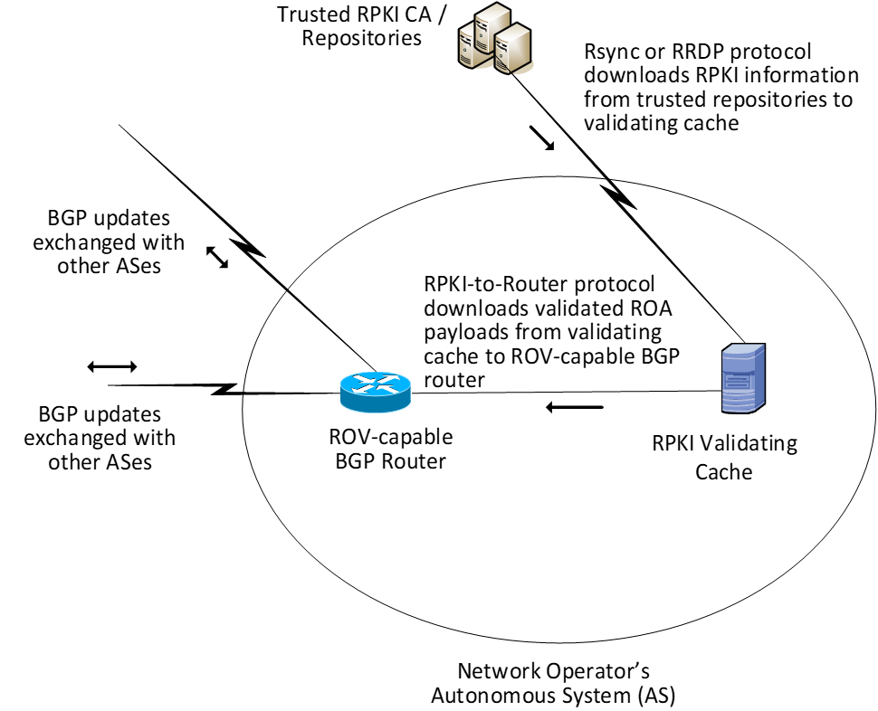
The network operator must deploy two components to perform ROV:
RPKI VC
- The Remote Synchronization (rsync) protocol is required to support interoperability between the RPKI VC and the trusted RPKI repositories. RPKI Repository Delta Protocol (RRDP) [RFC_8182] is also supported by some RIRs for this same purpose.
- The RPKI-to-router protocol [RFC_6810] is required to support interoperability between the RPKI VC and the local ROV-enabled routers, route reflectors, and route servers.
ROV-enabled BGP routers
ROV policy options should be configured on these routers according to network operator policy and according to the network operator’s status:
- Stub AS (i.e., Enterprise) ROV policy configurations
- Transit AS (i.e., ISP) ROV policy configurations
- Intra-AS ROV policy configuration (iBGP ROV signaling [RFC_8097], monitoring, and management)
It is a matter of local policy regarding what action should be taken when an incoming BGP route update is determined to be valid, invalid, or not found. However, the particular actions that are configured to be performed will likely depend on the location of the BGP router that is validating the update (i.e., whether it is located within an ISP that the advertisement is transiting, whether it is located in a stub network, and whether it is an Internet Exchange Point router) as well as on the business model of the entity performing the ROV. More discussion of the considerations related to ROV policy are discussed in the Outcome section (Section 6).
5.1.2. RPKI Reference Architecture
The RPKI reference architecture is used by address holders to create, sign, manage, and store ROAs. ROA information is the foundation on which routers and networks perform ROV. However, not all address holders share a single, uniform perspective of the RPKI reference architecture. Address holders may create ROAs by using either the hosted model or the delegated model, and the structure of the RPKI reference architecture differs according to which of these models is being used. Figure 5-2 (Section 5.1.2.1) depicts the RPKI reference architecture as implemented by address holders using the hosted model, and Figure 5-3 (Section 5.1.2.2) depicts the RPKI reference architecture as implemented by address holders using the delegated model.
5.1.2.1. Hosted-Model RPKI Reference Architecture
Figure 5-2 The Hosted-Model RPKI Reference Architecture
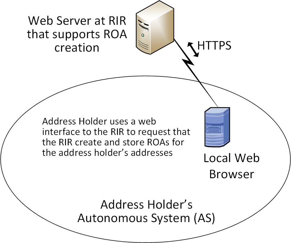
Figure 5-2 depicts the reference architecture for a hosted-model RPKI. As can be seen in the figure, an address holder wishing to use the hosted model of RPKI for ROA creation and storage needs to only have a web interface to the RIR or other authority from which it was allocated its addresses and other resources. As with Figure 5-1, this architecture is not intended to represent physical connectivity among the architecture components. Instead, it is meant to illustrate how they exchange information with each other.
In the hosted model, an RIR (or other authority) is responsible for operating an RPKI CA and repository. The RIR creates and signs ROAs for resources that are within the region that it oversees and that it has allocated. It also stores the ROAs in its repository. The address holder uses a tool (i.e., a web interface) to request that this RIR or other authority create, sign, manage, and store ROAs for its addresses on its behalf. In this model, the address holder does not have any responsibility to stand up or maintain a CA or repository or to directly create or maintain any of the RPKI information stored in it. All tools and applications for creating ROAs reside in the RIRs (or another organization that is hosting the RPKI service). RIRs provide the infrastructure and tools to create and store EE certificates, ROAs, and other RPKI information. Network operators are able to pull ROA information from the RIR (or other authority) repositories and use it to perform ROV.
5.1.2.2. Delegated-Model RPKI Reference Architecture
Figure 5-3 The Delegated-Model RPKI Reference Architecture
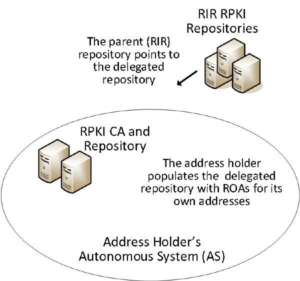
Figure 5-3 depicts the reference architecture for the delegated-model RPKI. As can be seen in the figure, the delegated model of RPKI for ROA creation and storage requires that two components be set up, operated, and maintained by the address holder: a CA and a repository. As with Figure 5-1 and Figure 5-2, this architecture is not intended to represent physical connectivity among the architecture components. Instead, it is meant to illustrate how they exchange information with each other.
In addition to setting up these components, the address holder must obtain an authorization to sub-allocate these resources from the RIR or other authority from which it received its address and other resource allocations as well as a CA certificate for these resources. The address holder must store the private key of its delegated RPKI key pair, exchange the public keys of the key pairs that it creates with its RIR, and store the resource certificates and ROAs in its repository. The CA certificate that the address holder receives from its RIR attests to the fact that the resources have been allocated. When it sub-allocates resources, the address holder may use its CA certificate to issue resource certificates that attest to these sub-allocations. If the address holder has customers to which it sub-allocates addresses, it can offer a hosted model of RPKI to its customers by creating and storing ROAs on behalf of those customers. Alternatively, if the resource holder has customers who want to set up their own delegated model of RPKI, it can authorize them to do so and can provide them with CA certificates attesting to their sub-allocations.
The address holder uses its CA certificate to generate EE certificates and thereby create and sign ROAs for addresses in its allocation, rather than rely on the RIR (or other authority) to do so. Once it creates and signs ROAs, it stores them in its repository and makes them available to VCs via the rsync or RRDP protocol. Network operators performing ROV are able to locate the delegated repository because the repository of the RIR (or other authority) that allocated the resources to the address holder will point to the delegated repository. Hence, although the parent repository is not actually part of the delegated RPKI reference model, the fact that it points to the delegated RPKI repository is crucial.
Because the applications and infrastructure for creating and storing ROAs reside in the address holder’s network, the address holder itself, rather than an RIR or other outside entity, is responsible for the accessibility, robustness, and responsiveness of the delegated CA and repository. As the operator of the CA and repository, the address holder is also responsible for resource certification maintenance; ROA creation, maintenance, and revocation; as well as RPKI management, monitoring, and debugging, as needed. For many organizations, the responsibilities of running a delegated CA, such as the availability and complexity of setting up a CA in a secure fashion, the relative lack of availability of software products supporting the delegated model, developing a Certification Practice Statement, maintaining hardware security modules, and managing the delegated model repository, are found to be burdensome. In addition, there are many issues with running a CA in a delegated model [NIST_SP_800-57_Part_2], [RFC_6484], [RFC_7382]. Available products for supporting the delegated model are limited and were not offered for this project. Consequently, the proof-of-concept demonstration focused mostly on the hosted model.
5.2. Combined ROV and RPKI Reference Architecture Example
Figure 5-4 depicts examples of all three reference architectures (ROV, hosted RPKI, and delegated RPKI) in one realistic network diagram. It shows three ASes (AS A, AS B, and AS C), each of which is capable of participating in RPKI-based ROV, both as a network operator and as an address holder. Figure 5-4 also includes icons representing RIR RPKI CAs and repositories.
Figure 5-4 Example ROV and RPKI Reference Architectures
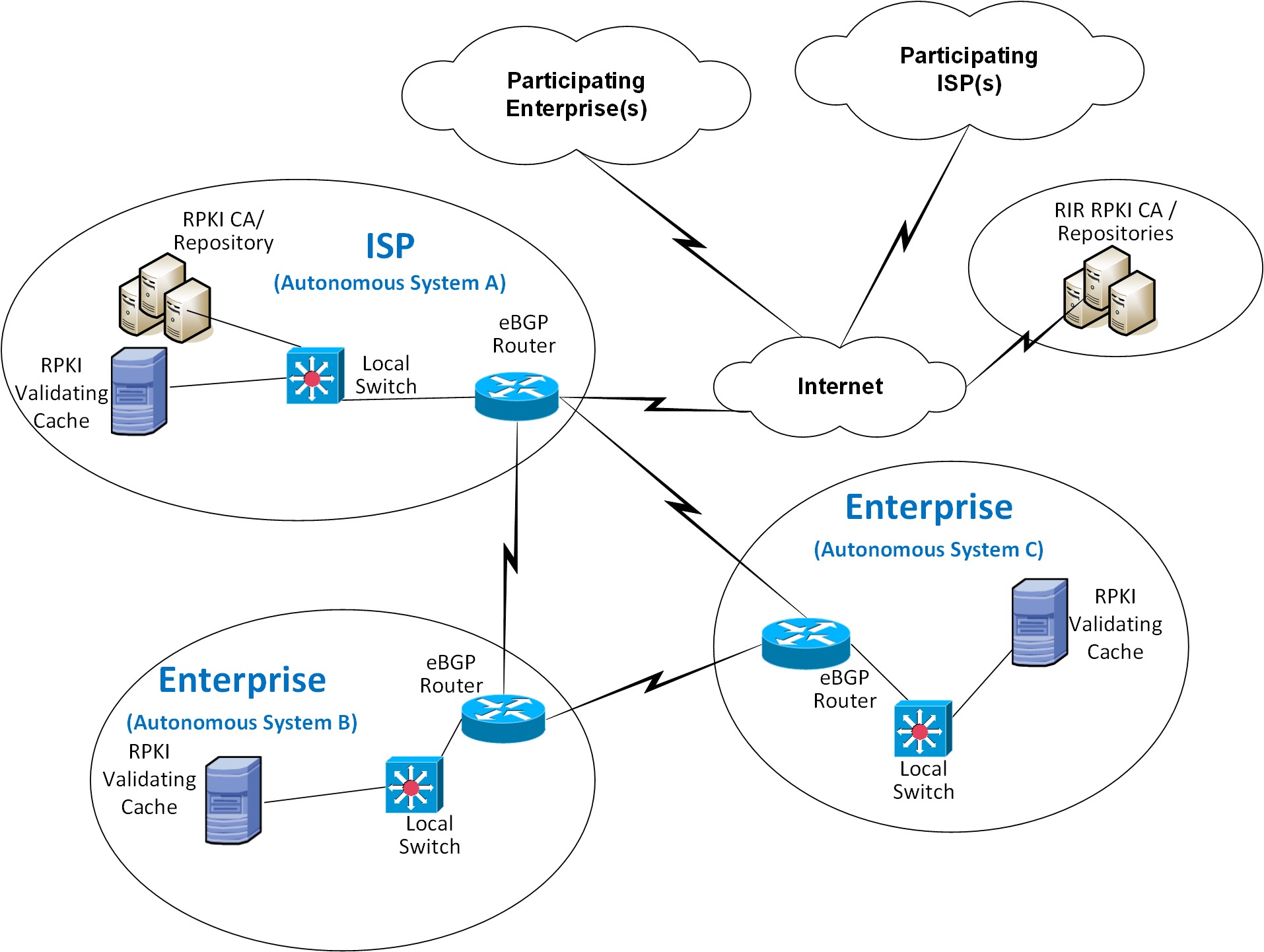
Viewing the architecture in Figure 5-4, in terms of its depiction of address holders, AS A represents an address holder that is implementing the delegated model of RPKI. This AS has set up its own CA and repository and is responsible for creating, signing, and storing ROAs for the addresses that it holds and for any addresses that it may sub-allocate to its customers. ROAs for all addresses that have been allocated to AS A must be downloaded from the repository that is associated with AS A. Assuming that AS A received its address allocation from an RIR, that RIR’s repository will point to AS A’s repository.
On the other hand, AS B and AS C represent address holders that are implementing the hosted model of RPKI. They have not set up their own CA or repositories. When they want to have ROAs created for the addresses that they hold, they must request that the entity that allocated the addresses to them creates, signs, and stores the ROAs on their behalf. AS B or AS C may have received its address allocation from its RIR, in which case it would use a tool (i.e., a web interface to an RIR tool) to request that the RIR creates, manages, and stores its ROAs. Alternatively, AS B or AS C may have received its address allocation from its ISP (i.e., from AS A). In this case, it would rely on AS A to create, manage, and store its ROAs.
Viewing the architecture in Figure 5-4, in terms of its depiction of network operators, all three ASes are network operators that are capable of performing ROV on all BGP updates that they receive. To perform ROV, a network operator must have an ROV-capable router, a VC (local or remote), and the ability for its VC to connect to its RPKI trust anchor (i.e., to the repository associated with AS A or to one of the RIR repositories).
Usage scenarios for ROV and for the RPKI hosted and delegated models are discussed in Section 5.3.
5.3. Usage Scenarios
5.3.1. ROV Usage Scenario
Figure 5-5 depicts the steps of an ROV usage scenario.
Figure 5-5 Route Origin Validation Usage Scenario
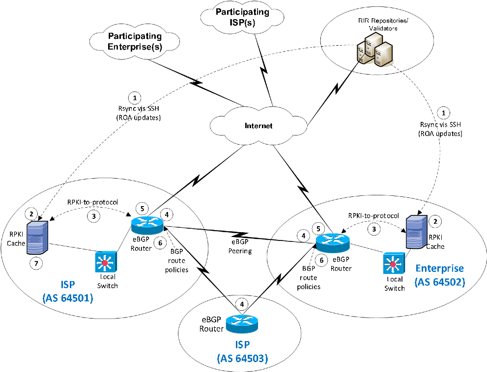
In this scenario, it is assumed that some address holders have created ROAs for the addresses that they hold. These ROAs are stored in the RPKI repository system, and network operators use these ROAs as the basis on which to perform the ROV. The steps of the ROV usage scenario, which are performed by AS 64501 and AS 64502 in their role as network operators, are as follows:
- ROA information is pulled down to the RPKI VC (labelled “RPKI Cache”) in AS 64501 and AS 64502 by using the remote file synchronization protocol rsync or RRDP between the RIR repositories and the VC.
- The RPKI VC receives all ROAs and certificates from the RIR repositories and validates this information.
- In AS 64501 and AS 64502, the RPKI VC communicates with the local eBGP router to send validated ROA payload (VRP) data to the router using the RPKI-to-Router protocol.
- Each eBGP router receives BGP updates from its neighbors.
- Each eBGP router checks the BGP updates against the VRP information received from the RPKI VC and uses this information to evaluate each update as valid, invalid, or not found.
- Each eBGP router makes a routing decision, based on ROV policies, regarding what to do with the route. (Generally, if the route is found to be valid, then it will be accepted. How invalid or not found routes are acted upon depends on local policy.)
5.3.2. Hosted-Model Usage Scenario
To understand the hosted model of RPKI in the context of Figure 5-2, assume that both AS 64501 and AS 64502 (in their role as address holders) have received their IP address allocations from their RIRs. These ASes are responsible for ROA creation, maintenance, and revocation for the addresses that they hold. However, they do not have a locally deployed CA or repository. To create ROAs, these ASes would have to use the hosted model. They would register with their RIR and use its web interface to request that it create, sign, and store ROAs for the addresses that they were allocated by that RIR.
5.3.3. Delegated-Model Usage Scenario
In the context of Figure 5-6, the ISP in AS 64501 is hosting a delegated model of RPKI. It is authorized by the RIR from which it received its IP addresses to sub-allocate those addresses and issue CA certificates for those sub-allocations. It has set up its own CA to create and sign ROAs for these addresses, as well as a repository to store these ROAs and other RPKI data and make them available to network operators that want to perform ROV. It has also ensured that its parent RIR repository points to the repository that is associated with its own AS.
Figure 5-6 Delegated-Model RPKI Usage Scenario
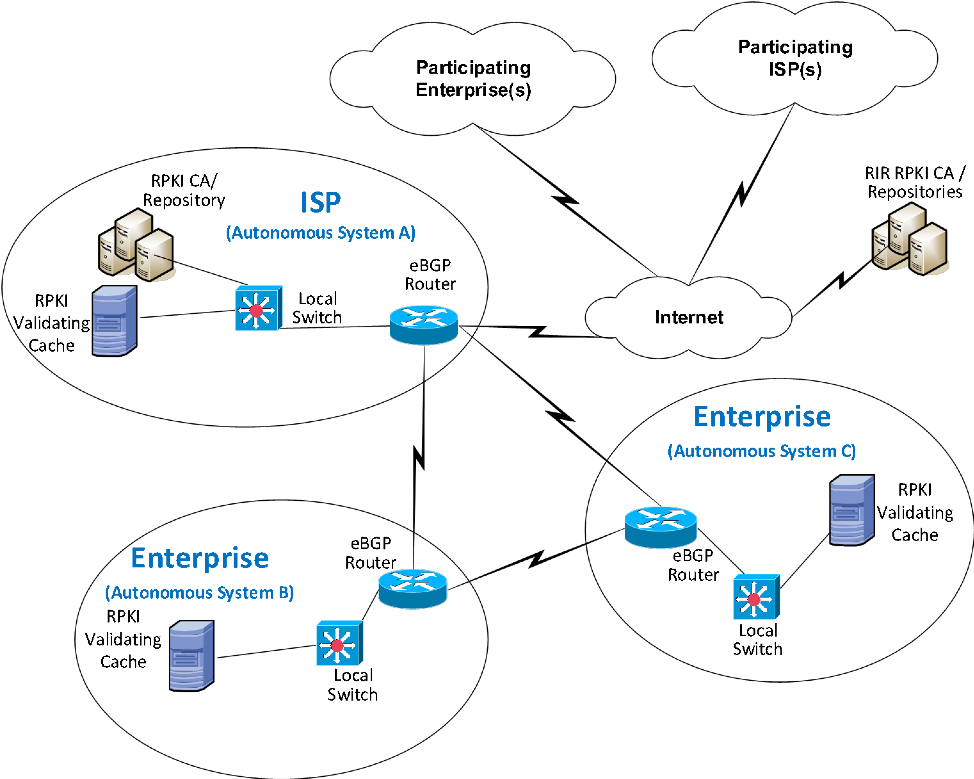
5.4. SIDR Laboratory Architecture
The SIDR laboratory’s physical architecture is depicted in Figure 5-7. It consists of virtual and physical hardware and a physical circuit to CenturyLink, which provides connectivity to the internet where the RIRs reside. The architecture is organized into eight separate networks, each of which is designed to represent a different AS. For example, the network labelled 10.10.0.0/16 represents a transit ISP with AS 65501, the network labelled 10.50.0.0/16 represents a stub enterprise network of an organization with AS 65505, etc. The physical hardware mainly consists of the routers performing ROV and the firewalls that protect the lab infrastructure. The virtual environment hosts the various software components needed to implement the ROV and RPKI reference architectures: a local RPKI repository in AS 65501 that is needed to implement the delegated model of RPKI and various VCs in several ASes that are needed to perform ROV. Four network operators are capable of performing ROV, each of which is depicted as having a local VC: AS 65501, AS 65504, AS 65505, and AS 65507. AS 65500, AS 65502, AS 65503, and AS 65508 do not have VCs and therefore lack the necessary infrastructure to perform ROV. In Figure 5-7, AS 65508 is colored red to represent a malicious attacker that may originate unauthorized BGP updates in an attempt to hijack routes.
Figure 5-7 SIDR Lab Physical Architecture
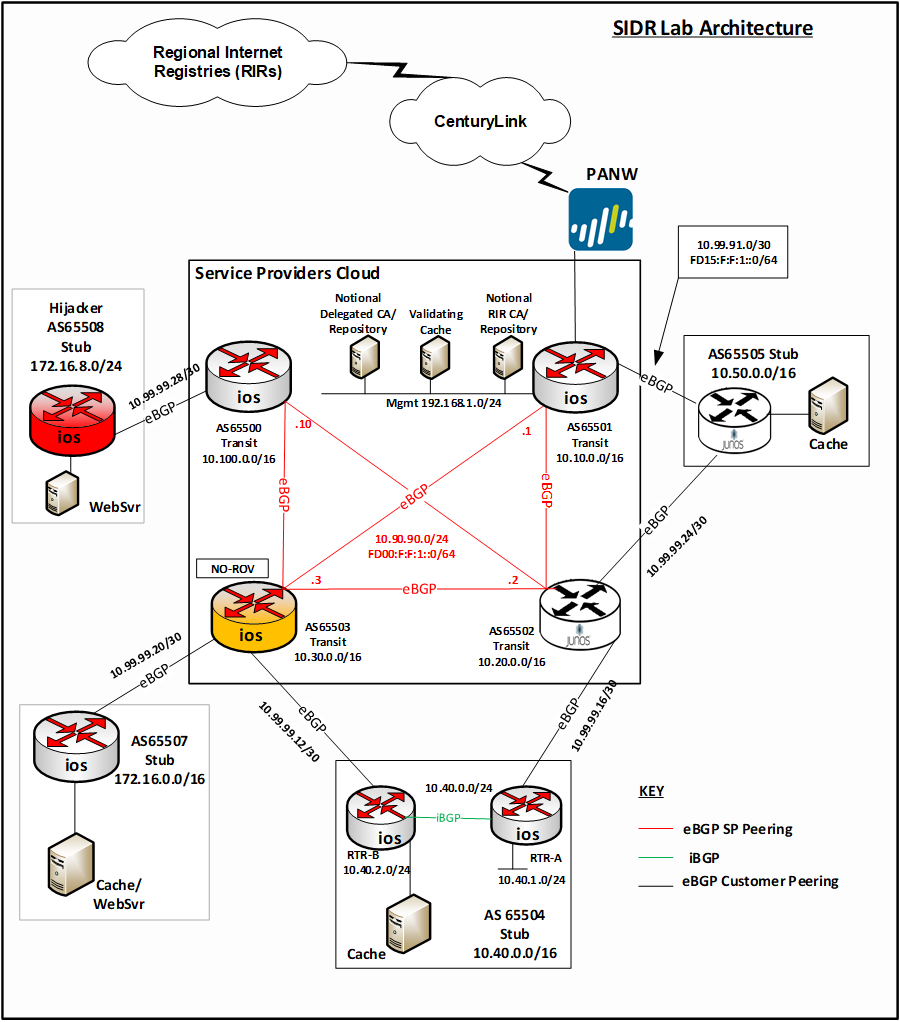
The architecture is designed to support a demonstration of both the hosted model and the delegated model.
Unfortunately, for the hosted model, we did not have address allocations from RIRs, or agreements in place with RIRs, that would give us access to the RIR to create and store ROAs at their repositories. To demonstrate the hosted model without access to RIR ROA creation tools, we set up a root CA and repository in AS 65501 (denoted by the Notional RIR CA/Repository icon in Figure 5-7) and used it to represent a notional RIR. ROAs for AS 65504 and AS 65507 could be stored in the Notional RIR repository just as they would typically be stored in an RIR repository if they had received their address allocations directly from an RIR rather than from our notional RIR.
In Figure 5-7, the delegated model is represented by the icon labelled Delegated CA and Repository that is located within AS 65501 in the Service Providers Cloud. This delegated CA is set up as a child of the notional RIR CA, which, for purposes of simplifying the design, resides on the same subnet. The delegated CA represents a delegated model of RPKI infrastructure that AS 65501 has set up in its own AS to host its own repository and to create and store certificates and ROAs for the addresses that have been allocated to it by the notional RIR. It can store ROAs not only for AS 65501 in this repository, but also for AS 65501’s customer, AS 65505, to whom AS 65501 is assumed to have sub-allocated addresses. Hence, while the delegated CA and repository in AS 65501 represent a delegated RPKI model from the perspective of AS 65501, this model also offers a hosted RPKI service to AS 65505, which does not operate its own repository. As a customer of AS 65501, AS 65505 relies on AS 65501, rather than on the notional RIR, to create, sign, store, and maintain its ROAs.
For purposes of ROV, network operators in all ROV-capable ASes were able to pull down ROAs and other RPKI information not only from the real RIRs, but also from the notional RIR repository and the delegated repository in AS 65501.
6. Outcome
This section discusses ROV-related issues, lessons learned, and best practices.
6.1. ROV Policy Configuration Options
The action to be taken when an incoming BGP route advertisement is determined to be valid, invalid, or not found is determined by local policy. Ultimately, when RPKI adoption has attained a high level of maturity, it is expected that the recommendation will be to drop invalid routes. Until then, invalid routes can be observed and noted, or perhaps assigned lower local preference (LP) values to de-preference them by using policies.
Both Cisco and Juniper provided example policies for organizations to consider deploying with their ROV-capable routers. One candidate policy is to not drop invalid BGP updates. Another candidate policy is to associate varying LP values with routes, depending on how the update that advertised the route is evaluated. For example, routes received in valid updates may be given an LP value higher than the default, routes received in not found updates may be given the default LP value, and routes received in invalid updates may be given an LP value lower than the default.
In addition, researchers affiliated with NIST and the IETF SIDR Working Group are working to investigate and develop how the ROV-capable routers should best use the ROV state in route selection policy.
6.2. Implementation Status of RPKI Components
6.2.1. RPKI VC Component
The deployment or use of a VC (local or remote) is required for the support of ROV. As of this writing, we are aware of three open-source implementations of VCs that are available. The demonstration build used two of these VCs.
The third open-source VC implementation is also available from Raytheon BBN Technologies. Organizations wishing to adopt ROV may wish to investigate the use of this tool, which is called Rpstir. Its software can be found at https://github.com/bgpsecurity/rpstir.
Organizations that deploy open-source VC software should be aware of the possibility that they may eventually be required to assume some responsibility for keeping the software updated and maintained.
6.2.2. RPKI CA and Repository Components
Address holders willing to use the hosted model for ROA creation and storage can depend on their RIR to provide these services for them. Organizations wishing to deploy their own delegated model for ROA creation, maintenance, and storage will need CA and repository software. As of this writing, we are aware of one open-source implementation of CA and RPKI repository software that is available. We were able to use this software successfully to set up a delegated model CA and repository. However, it is not a turnkey product. Rather, its implementation requires a considerable staff investment. Organizations wishing to use the delegated model for RPKI to host their own CA and repository should be aware that, to do so, they will have to either develop their own software or take responsibility for maintaining and supporting the open-source implementation. We did not subject this demonstration implementation to stress, robustness, availability, or other testing that would typically be required before an organization would want to place it into operational use.
6.2.3. ROV-Capable Routers
The commercial implementations of ROV-capable routers that we demonstrated are well-documented and well-supported and can be used easily out of the box. See Section 7, Functional and Robustness Results, for details regarding their functionality.
6.2.4. Lessons Learned
- One of the most important lessons learned from the implementation and testing of the RPKI technologies is to ensure that software properly implements RPKI-based ROV based on the [RFC_6811] and [RFC_8210] specifications. Some versions of an OS may not have the capabilities specified in the RFCs.
- It is important to note that the default configuration for some routers is to exclude invalid prefixes from the routing table, whereas, for other routers, specific policy has to be defined to establish dispositions for valid, invalid, and not found prefixes. Some routers presume that all local routes, including iBGP learned routes, default to valid, especially when community strings are not sent [RFC_8097]. An additional lesson learned worth mentioning is that some routers may be configured for one additional state of “unverified” via a policy statement to indicate the case in which a router did not perform ROV on the particular route. Note: As of September 2018, [RFC_8481] states that all routes should be evaluated and have their state set. After the validation process is complete, the operator can apply any policy based on the evaluation state.
- With the use of RPKI, BGP ROV results in BGP routes that are evaluated as either valid, invalid, or not found. While accepting the valid routes for usage is the default recommendation and is non-controversial, organizations should use their local route selection policies for routes that are invalid or not found. Initially, organizations can simply log the fact that routes have been evaluated as invalid or not found, without changing the routes’ behavior at all. This would be a risk-free method of initiating the adoption of RPKI ROV by monitoring how ROV would affect the routing if policies would be applied to the validation result. However, no increased level of route origin assurance would result from this level of adoption either. Such an initial adoption period—during which all routes are evaluated; statistics are gathered regarding the number of valid, invalid, and not found routes; but no special action is taken for invalid or not found routes—could be helpful, with respect to allowing organizations to determine the extent to which various potential policies that they may be considering using might affect routing.
- When configuring an RP, the trust anchor locator (TAL) of the five RIRs must be provided. In most VCs, four out of five TAL files are pre-loaded. The fifth TAL file, for ARIN, has to be downloaded. One should note that there are three TAL file formats: [RFC_7730], [RFC_6490], and RIPE NCC Validator format. It’s important to be mindful of the TAL file format that the VC uses.
- On iBGP connections, we observed a slight increase in the number of BGP updates when the validation result was conveyed in iBGP using the extended community [RFC_8182]. The reason for this is that prefixes that originally could be incorporated into one update might not have been able to be incorporated into the same update anymore due to different validation results. Additionally, if selected updates change the validation result, then the router will resend the updates with the updated community string. In general, by turning on ROV, there will likely be a slight increase in the number of updates sent. An otherwise stable route whose configuration state changes will be re-signaled with the new extended community as its validation state changes.
Delegated Model
- Whether an address holder should use the hosted or delegated model for issuing ROAs depends on several factors. If the address holder is a large ISP that sub-allocates address space to various subscriber organizations, then it may well determine that it will be to its benefit to stand up its own CA infrastructure and to deploy the delegated model. The hosted model is likely preferable for smaller address holders that will not be sub-allocating their address space to other organizations and that do not necessarily have the resources to deploy, configure, operate, and maintain their own CA infrastructure and RPKI repository—and do so in a way that assures its accessibility, robustness, and responsiveness. Regardless of the model used, all address holders should create ROAs for their addresses in order to enable network operators and RPs to be able to verify the origin of route advertisements that are sent out advertising the address holder’s prefixes.
- The documentation for the rpki.net toolkit, which implements the CA and repository, contains gaps. Moreover, we found that the rpki.net toolkit would benefit from additional debugging tools and guidance. It is, at times, unclear how the agents are interacting with each other. During set-up and for learning purposes, it may be beneficial to run a traffic scanner to see what is being passed between hosts. Through trial and error, we identified the steps needed to complete installation and configuration. We provide these steps in Volume C of this Practice Guide.
- It should be possible to declare an ROA with a time-out. It did not appear that the rpki.net tool could issue an ROA with an explicit time-out.
7. Functional and Robustness Results
We conducted a functional and robustness evaluation of the SIDR example implementation, as deployed in our laboratory, to verify that it worked as expected. The evaluation was intended to verify that the example implementation functioned as expected from several different perspectives:
- a resource holder (e.g., an ISP that sub-allocates the address space it holds and that provides addresses to its customers) setting up its own CA as a delegated RPKI participant and offering either a hosted model or a delegated model (or both) of RPKI support to its customers (i.e., obtaining CA certificates; creating EE certificates; creating, signing, and revoking ROAs; and uploading ROAs and other objects to the RPKI repository)
- an address holder protecting the addresses it holds, by creating and managing ROAs for those addresses by using either the hosted or delegated model
- an RP operating a BGP router and performing ROV on all of the route prefix advertisements that it receives to determine if they are valid, invalid, or not found, and applying configured policy based on the result
In all cases, the evaluation tested functionality, using both IPv4 and Internet Protocol Version 6 (IPv6) addresses. Both virtual and physical ROV-capable routers were used. Access to a live physical circuit was provided by CenturyLink. The circuit delivers full internet routes into the lab via live BGP peering and provides connectivity to the internet where the RIRs reside.
Some testing was performed using live and interactive full internet routes, while other testing was performed using static data injected via a predefined test harness created by NIST. The test harness provides a BGP traffic generation and collection framework—BGPSEC-IO (BIO) [NIST_BGP-SRx]—as well as a mechanism for providing RPKI data by using an RPKI traffic generator, both part of the NIST Border Gateway Protocol Secure Routing Extension (BGP-SRx) Software Suite [NIST_BGP-SRx]. The harness environment was used to ensure that the test scenarios performed can be regenerated using carefully manufactured static data that is pre-populated and controlled via traffic generators and measurement tools.
The VC used in both the functional and robustness tests was the RIPE NCC RPKI Validator Version 2.24. It was chosen because of its inherent flexibilities, including the ability to dynamically add local (white list) entries.
Whereas the RPKI delegated model that was developed in-house was used for preliminary functional tests, all of the documented functional tests were done using the hosted model with locally added entries for ROA data. These entries were added via web-interface/simplified local internet number resource management (SLURM) workload manager files, in the case of the Harness test environment for RIPEv2. We were able to install RIPEv3, on Linux systems by using the binary RPM Package Manager (originally Red Hat Package Manager) distribution. At the time of testing, RIPEv3 had some bugs that prevented us from using it. One issue was the incapability of processing large SLURM files (25-percent coverage of the routing table). This seems to be resolved in the latest binary version. An additional, more pressing issue was that RIPEv3 does not recognize ROA data if no TAL file is configured. The validator reports “no data” to the router. This issue has been reported and is expected to be resolved in a future release.
Figure 7-1 depicts the test bed using the test harness (BGP traffic generation and collection framework [BGPSEC-IO]). Figure 7-2 depicts the test bed using live traffic.
Note: The test bed using live traffic has a Palo Alto Next-Generation Firewall (PANW) that sits between the ISP and the internal environment to allow only the relevant traffic for this project.
Figure 7-1 SIDR Testbed Using the Test Harness
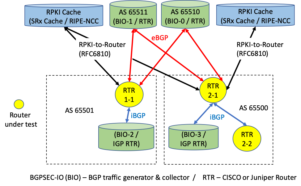
Figure 7-2 SIDR Testbed Using Live Traffic
7.1. Assumptions and Limitations
This functional evaluation has the following limitations:
- It is neither a comprehensive test of all security components nor a red-team exercise.
- It cannot identify all weaknesses.
- The hardware components that were part of the demonstration build were typical of enterprise edge routers or small aggregation routers.
- The scaling tests that were performed included numbers of routers and peers that are typical of enterprise interconnectivity. In this context, we used routing tables of sizes similar to the full current internet routing table (approximately 700,000 routes).
- ISPs will require further testing, in terms of the number of routes, route changes, and sources of routes that are larger than the current global routing table, to handle future expected growth. In addition, carriers will need to test geographically distributed validators as well as anycast-capable validators. Testing of the impact of timing issues will also be required.
The functional evaluation also does not include the laboratory infrastructure security evaluation. It is assumed that its devices are hardened. Testing these devices would reveal only weaknesses in implementation that would not be relevant to those adopting this reference architecture. It is also important to note the need to harden the implementation if this Practice Guide is used by others, such as enterprise networking organizations or ISPs, as a roadmap for deployment. Although Section 4.4 and Section 4.5 describe [NIST_SP_800-53] controls addressed by the demonstrated capabilities, they do not list the full set of [NIST_SP_800-53] controls that apply to routers and routing systems. For example, issues such as signature validation and transfer protocol security must be addressed in any operational implementation.
Section 11 of the RPKI-to-router specification [RFC_6810] provides guidance regarding securing the protocol. The security considerations taken for our demonstration build (e.g., firewall rules) are documented in Volume C of this Practice Guide.
7.2. Functional Test Requirements
This section provides a summary of the functional requirements that were tested. A detailed table of functional test requirements and their corresponding tests is provided in Appendix E.
7.2.1. ROV Functional Requirements
The SIDR example implementation included a capability for BGP routers to perform ROV on all routes that they receive in BGP update messages. The router was capable of accurately establishing an initial validation state (valid, invalid, or not found) for a given route, and marking the route accordingly. The router was also capable of accurately reevaluating that route’s validation state after RPKI test data has been perturbed and re-marking the route (where applicable). Tests were performed for the following cases:
- routes received through eBGP and iBGP updates
- local static routes redistributed into BGP
- routes redistributed into BGP from an interior gateway protocol (IGP)
- routes redistributed into BGP from an iBGP
- router cache synchronization
7.2.2. Delegated RPKI-Model Functional Requirements
The SIDR example implementation included the capability for a resource holder to set up its own delegated CA, create its own repository, and offer a hosted service to its customers, including the ability to publish customer ROAs to its repository, delete customer ROAs from its repository, and have customer ROAs expire from its repository. The ROAs in this delegated CA repository were included in the RPKI data that RPs downloaded to their VCs, and VRPs derived from these ROAs were provided to RP routers via the RPKI-to-router protocol.
7.3. Functional Test Findings
Securing the routing system is an important task for the internet. While RPKI-based ROV does not claim to solve all inherent security issues with the use of the BGP routing protocol, it provides significant progress in helping resolve some of the issues surrounding BGP route hijacks. To verify the maturity and effectiveness of RPKI technology, numerous functionality tests were performed using the prototype implementation in the NCCoE lab. It is important to note that most issues encountered during functional tests were quickly resolved either by installing an updated router OS provided by a vendor or by setting up some optional configuration.
Not all proposed test cases could be performed. The following observations resulted from completing the functional tests:
- Not all RIRs currently support RRDP.
- RIRs implement the hosted model differently from each other. RIRs offer different user interfaces and different RPKI support services.
- At the time of our testing, some interoperability issues were discovered in the iBGP signaling of the RPKI validation state between the various
implementations under test.
- During the course of the project, these issues were fixed in the affected implementations. Prerelease fixed versions of implementations were re-tested, and the interoperability issues were resolved.
- We expect that future full releases of the affected implementations will incorporate these fixes as well.
- Some versions of router software provided to this project did not correctly evaluate aggregated routes with the AS_SET attribute. Bug reports were filed with
the implementors.
- Users should verify support for proper BGP update validation in the presence of AS_SET.
- It was discovered that vendors evaluate locally learned routes (iBGP) differently. For example, some implementations default to valid for locally learned routes, while others determine the validity of locally learned routes via policy statements.
- There were router-to-VC interaction cases in which serial requests of delta ROA information did not completely conform with [RFC_6810]. Some
VC versions do not support deltas in the RPKI-to-router protocol implementation [RFC_6810]. With the current scale of the deployed RPKI, it
does not seem to produce issues; however, with a larger amount of RPKI coverage, this could cause unnecessary delays, especially for high poll frequencies.
- Users should verify support for incremental updates in the RPKI-to-router protocol.
7.4. Robustness Findings
To test the impact of RPKI ROV on BGP routing convergence, we initially measured the convergence time of a router with one peer by using a full BGP table dump (approximately 700,000 BGP routes) without using ROV or any other policies to gather a baseline. We repeated the tests by adding RPKI origin validation by using 25%, 50%, 75%, and 100% ROA coverage. With no additional routing policies added, we observed an approximate increase of two percent to seven percent in convergence time across all tested platforms.
Note that this finding only provides a baseline from a single router standpoint. Scalability scenarios were not performed. Scalability of RPKI ROV would include other aspects of an enterprise or an ISP’s network infrastructure design. Enterprises and ISPs should identify their own scalability requirements for further evaluation.
8. Recommendations for Follow-on Activities
8.1. Standards Initiatives
In the course of our testing, the SIDR Project identified clarifications that might be made to some ROV-related and RPKI-related IETF specifications to potentially reduce ambiguity and improve interoperability. The IETF is progressing with such clarifying specifications.
8.2. Future Demonstration Activities
As was discussed earlier in this document, while ROV can help detect when an ISP or enterprise originates an update for an address that it is not authorized to announce (route hijacking), it is not able to detect when an AS makes an unauthorized modification of routing path information in a BGP update that it forwards. Such path modification attacks can deny access to internet services, detour traffic, misdeliver traffic to malicious endpoints, undermine protection systems, and cause routing instability. The BGPsec protocol, which has recently been finalized within the IETF, is designed to protect against such path modification attacks. There are currently open-source prototype implementations of BGPsec available (e.g., NIST BGP-SRx Software Suite [NIST_BGP-SRx], and the Parsons-enhanced BIRD implementation [Parsons_BGPSec]).
As commercial implementations also become available, the NCCoE may consider further demonstration in support of resource certification in ISPs that have many customers with provider-independent prefixes. The NCCoE will also consider a project to build and demonstrate a BGPsec solution by using available protocols, products, and tools and publish a practice guide of lessons learned.
RPKI-based BGP ROV and BGPsec implemented together have the potential to greatly increase the security of the BGP routing protocol, enabling an entity that receives a BGP update to validate that the AS that is listed as the originating AS is, in fact, the AS that originated the update, that the path to that AS that is in the update has not been modified in an unauthorized manner, and that the AS that originated the update was authorized to do so.
BGPsec and ROV work hand-in-hand to secure internet routing. A follow-on project to promote the adoption of BGPsec can be expected to increase the adoption of not only BGPsec, but also of ROV. Organizations that implement one can be expected to be eager to implement the other.
8.3. Tool Development and Maintenance
As was mentioned earlier, commercial routers that support ROV are available from multiple vendors, and these products are supported and maintained. Some other key components, such as VCs, publication point software, and RPKI and CA tools, however, are not available with typical commercial support and backing. Ideally, commercial vendors will make this software available and will support and maintain these products.
Organizations wishing to use the delegated model for RPKI to host their own CA and repository should be aware that, to do so, they will have to either develop their own software or take responsibility for maintaining and supporting the open-source implementations.
8.4. Infrastructure Testing
Further testing on scalability and robustness issues with equipment and configurations with a scale similar to that of ISP networks should be considered.
The security of the infrastructure used to deploy either a hosted or delegated model will need to be tested. If carriers are using either model, then the integrity and availability of RIR implementations will directly affect the operation of the network. For example, a compromise of an RIR may lead to accepting incorrect routes or denying valid routes, or it may make the service unavailable. A DoS of the RIR may make updates of RPKI information unavailable. That may impact operations, due to stale routing data. In addition, the security and availability of the various communication paths will need to be tested. This includes transferring RPKI data from a repository to a VC and from a VC to routers.
8.5. Research Activities
Additional research is needed to determine how ROV-capable routers should best use the ROV evaluation state in the route selection policy. As was mentioned earlier, researchers affiliated with NIST and the IETF Working Group are investigating this question. Ideally, in the future, it will be possible to easily configure various policies based on this research in ROV-capable routers.
Appendix A Application of Systems Security Engineering: Considerations for a Multidisciplinary Approach in the Engineering of Trustworthy Secure Systems (NIST SP 800-160) to the Secure Inter-Domain Routing Project
The Secure Inter-Domain Routing (SIDR) Project used [NIST_SP_800-160] within a framework for planning and conducting the Internet Routing Security Project. [NIST_SP_800-160] addresses the engineering-driven perspective and actions necessary to develop more defensible and survivable systems, inclusive of the machine, physical, and human components that compose the systems and the capabilities and services delivered by those systems. It starts with and builds upon a set of well-established international standards for systems and software engineering published by the International Organization for Standardization (ISO), the International Electrotechnical Commission (IEC), and the Institute of Electrical and Electronics Engineers (IEEE), and infuses systems security engineering methods, practices, and techniques into those systems and software engineering activities. The objective is to address security issues from a stakeholder’s protection needs, concerns, and requirements, and to use established engineering processes to ensure that such needs, concerns, and requirements are addressed with appropriate fidelity and rigor early and in a sustainable manner throughout the life cycle of the system.
The full integration of the systems security engineering discipline into the systems and software engineering discipline involves fundamental changes in the traditional ways of doing business within organizations—breaking down institutional barriers that, over time, have isolated security activities from the mainstream organizational management and technical processes, including, for example, the system development life cycle, acquisition/procurement, and enterprise architecture. The integration of these interdisciplinary activities requires the strong support of senior leaders and executives, and increased levels of communication among all stakeholders who have an interest in, or are affected by, the systems being developed or enhanced.
The Internet Routing Security Project offered an opportunity to attempt to implement the principles underlying [NIST_SP_800-160] at the project level and to uncover any issues associated with project-level application of those principles.
[NIST_SP_800-160] defines systems security engineering as part of a multidisciplinary systems engineering effort that:
- defines stakeholder security objectives, protection needs and concerns, security requirements, and associated validation methods
- defines system security requirements and associated verification methods
- develops security views and viewpoints of the system architecture and design
- identifies and assesses vulnerabilities and susceptibility to life-cycle disruptions, hazards, and threats
- designs proactive and reactive security functions encompassed within a balanced strategy to control asset loss and associated loss consequences
- provides security considerations to inform systems engineering efforts with the objective to reduce errors, flaws, and weaknesses that may constitute security vulnerability leading to unacceptable asset loss and consequences
- identifies, quantifies, and evaluates the costs/benefits of security functions and considerations to inform the analysis of alternatives, engineering trade-offs, and risk treatment decisions [The term “risk treatment” as defined in [ISO 73] is used in [ISO_IEC_IEEE_15288:2015].
- performs system security analyses in support of decision making, risk management, and engineering trades
- demonstrates, through evidence-based reasoning, that security claims for the system have been satisfied
- provides evidence to substantiate claims for the trustworthiness of the system
- leverages multiple security and other specialties to address all feasible solutions to deliver a trustworthy, secure system
The Systems Security Engineering Framework [McEvilley15] provides a conceptual view of the key contexts within which systems security engineering activities are conducted. The framework defines, bounds, and focuses the systems security engineering activities and tasks, both technical and non-technical, toward the achievement of stakeholder security objectives and presents a coherent, well-formed, evidence-based case that those objectives have been achieved. The framework is independent of the system type and the engineering or acquisition process model and is not to be interpreted as a sequence of flows or process steps, but rather as a set of interacting contexts, each with its own checks and balances. The systems security engineering framework emphasizes an integrated, holistic security perspective across all stages of the system life cycle and is applied to satisfy the milestone objectives of each life-cycle stage. The framework defines three contexts within which the systems security engineering activities are conducted. These are the problem context, the solution context, and the trustworthiness context.
- The problem context defines the basis for an acceptably and adequately secure system, given the stakeholder’s mission, capability, performance needs and concerns; the constraints imposed by stakeholder concerns related to cost, schedule, and risk and loss tolerance; and other constraints associated with life-cycle concepts for the system.
- The solution context transforms the stakeholder security requirements into design requirements for the system; addresses all security architecture, design, and related aspects necessary to realize a system that satisfies those requirements; and produces sufficient evidence to demonstrate that those requirements have been satisfied to the degree possible, practicable, and acceptable to stakeholders.
- The trustworthiness context is a decision-making context that provides an evidence-based demonstration, through reasoning, that the system-of-interest is deemed trustworthy based upon a set of claims derived from security objectives.
The systems security engineering framework also includes a closed-loop feedback for interactions among and between the three framework contexts, and the requisite system security analyses to continuously identify and address variances as they are introduced into the engineering effort. The feedback loop also helps achieve continuous process improvements for the system.
The SIDR Project was not the development of an operational system from scratch; rather, it was a demonstration of a proof-of-concept platform composed of off-the-shelf components in order to enable legacy systems to mitigate a defined set of cybersecurity threats. As such, many longer-term life-cycle processes (e.g., supply, human resource management, configuration management, transition) were primarily treated only in the Practice Guide in explaining how the platform might be used operationally. The SIDR Project was planned and conducted in six phases: Initiation, Planning, Design, Execution, Control, and Closing.
This project took the following (often recursive) steps in demonstrating the adaptation and use of [NIST_SP_800-160] to provide a project planning framework for the internet routing project at the National Cybersecurity Center of Excellence (NCCoE):
- Develop, state, and support the value proposition of the candidate project for the following overlapping Communities of Interest:
- internet customers and users
- internet service providers (ISPs)
- routing product vendors
- security product vendors
- Define the project requirements:
- security objectives
- security requirements
- operational and design constraints
- success determination and/or measurement
- life-cycle security issues
- Describe, design, develop, and build the solution:
- specification of required components and component characteristics
- identify potential sources for components possessing the necessary characteristics
- define component-interface and related performance requirements
- solicit participation from sources of necessary components
- enter into collaboration agreements with sources of necessary components
- coordinate proof-of-concept architecture of composed security platform with collaborators
- build and demonstrate the security platform to realize the security aspects of the solution
- document the security platform’s performance against project requirements as evidence for the security aspects of the solution
- Document project results:
- demonstration of value proposition
- demonstrated security improvements and residual risks
- security platform build and integration details
- how to use the security platform in a manner that achieves security objectives
From an [ISO_IEC_IEEE_15288:2015] life-cycle point of view, the Initiation phase of the project mapped to the following processes:
- Organization Project Enabling Process
- Human Resource Management
- Technical Management Process
- Portfolio Management
- Project Assessment and Control
- Decision Management
- Risk Management
- Technical Process
- Business or Mission Analysis
- Stakeholder Needs and Requirements Definition
- Project Planning
- System Requirements Definition
- Architecture Definition Processes
The Planning phase mapped to the following [ISO_IEC_IEEE_15288:2015] life-cycle processes:
- Agreement Process
- Acquisition
- Supply [collaborator function]
- Project Enabling Process
- Risk Management
- Human Resource Management
- Quality Management
- Knowledge Management
- Technical Management Process
- Portfolio Management
- Project Planning
- Decision Management
- Risk Management
- Project Assessment and Control
- Information Management
- Measurement
- Quality Assurance
- Technical Process
- Business/Mission Analysis
- Architecture Definition
- Design Definition
- System Analysis
- Stakeholder Needs and Requirements Definition
- System Requirements Definition
- Implementation
- Integration
- Disposal
The Design phase mapped to the following [ISO_IEC_IEEE_15288:2015] life-cycle processes:
- Project Enabling Process
- Infrastructure Management
- Technical Management Process
- Portfolio Management
- Project Planning
- Decision Management
- Configuration Management
- Risk Management
- Project Assessment and Control
- Technical Process
- Business/Mission Analysis
- Architecture Definition
- Design Definition
- System Analysis
- Stakeholder Needs and Requirements Definition
- Implementation
- Integration
- Verification
The Execution phase mapped to the following [ISO_IEC_IEEE_15288:2015] life-cycle processes:
- Agreement Process
- Acquisition
- Supply [collaborator function]
- Project Enabling Process
- Infrastructure Management
- Quality Management
- Knowledge Management
- Technical Management Process
- Project Assessment and Control
- Configuration Management
- Risk Management
- Quality Assurance
- Technical Process
- Implementation
- Integration
- Verification
The Control phase mapped to the following [ISO_IEC_IEEE_15288:2015] life-cycle processes:
- Project Enabling Process
- Infrastructure Management
- Quality Management
- Knowledge Management
- Technical Management Process
- Project Assessment and Control
- Information Management
- Risk Management
- Quality Assurance
- Measurement
- Technical Process
- Implementation
- Integration
- Verification
The Closing phase mapped to the following [ISO_IEC_IEEE_15288:2015] life-cycle processes:
- Project Enabling Process
- Infrastructure Management
- Quality Management
- Knowledge Management
- Technical Management Process
- Project Planning
- Information Management
- Risk Management
- Quality Assurance
- Measurement
- Technical Process
- Business or Mission Analysis
- Implementation
- Verification
- Validation
Keeping the feedback aspect of the context framework in mind, we mapped the primary focus of each project phase to each of the context’s component elements as follows:
- The problem context:
- determining life-cycle security concepts – Initiation
- defining security objectives – Initiation
- defining security requirements – Initiation and Planning
- determining measures of success – Initiation and Planning
- The solution context:
- defining the security aspects of the solution – Planning and Design
- realizing the security aspects of the solution – Design and Execution
- producing evidence for the security aspects of the solution – Execution and Control
- The trustworthiness context:
- developing and maintaining the assurance case – Execution and Control
- demonstrating that the assurance case is satisfied – Control and Closing
Establishing the three contexts helped ensure that the engineering of the system was driven by a sufficiently complete understanding of the problem articulated in a set of stakeholder security objectives that reflected protection needs and security concerns—instead of by security solutions brought forth in the absence of consideration of the entire problem space and its associated constraints. Moreover, the approach resulted in explicit focus and a set of activities to demonstrate the worthiness of the solution in providing adequate security across competing, and often conflicting, constraints.
One will note that, as we moved from Problem to Solution to Analysis elements of the [NIST_SP_800-160] framework, the need for adaptation increased. This was partly due to the fact that the output of an NCCoE project is a proof-of-concept demonstration, not a finished commercial product or government system. Organizations adapting NCCoE security platforms to their own environments will necessarily alter the demonstrated solution as needed to fit their own physical, operational, and contractual environments and will perform trustworthiness analyses in the context of their own risk acceptance perceptions and constraints. In employing [NIST SP 800-160]_in this Internet Routing Security Project, the project engineers recognized that the candidate project involved the composition of several security-dedicated and security-purposed components in demonstrating upgrades to fielded systems while continuing to sustain day-to-day operations. Internet routing was accomplished using constantly evolving systems of systems. While the motivation for the proposed upgrades was reactive, with respect to already realized attacks, the critical nature of internet routing systems is such that the planned security enhancements cannot be permitted to disrupt internet operations. Although current internet routing systems are generally built on operating systems that have both known and unknown security deficiencies, it is not currently practical to retire critical elements of the existing systems. Consequently, the security platform as demonstrated necessarily retained many existing vulnerabilities. The composition of the platform needed to be engineered in a manner that reduced the consequences of its flawed foundation.
The systems security engineering aspects of the project also accommodated context sensitive considerations. Among these were the private-sector ownership, operation, and use of key internet components and the need to support widely varying stakeholder assessments of asset value and risk tolerance. Context sensitivity addressed multiple contexts and perceptions of return on investment.
The following material explains the project life-cycle framework elements to which the [NIST_SP_800-160] activities and tasks are mapped.
When mapped against the NCCoE’s project management framework, the activities and tasks took place at each of the following project phases, as identified in the subsections below.
A.1 Project Initiation
Project initiation activities included initiation, concept, and business-case-review milestones.
A.1.1 Initiation
The initiation milestone involved identifying the business need, developing a Rough Order of Magnitude (ROM) cost and preliminary schedule, and identifying basic business and technical risks. The outcome of the initiation phase was the decision to invest in a full business case analysis and preliminary project management plan. In the case of the SIDR Project, meeting the initiation milestone involved both NIST’s Information Technology Laboratory (ITL) Advanced Network Technology Division (ANTD) staff and NCCoE staff interactions with standards activities (e.g., the Internet Engineering Task Force [IETF]) and industry organizations (e.g., the North American Network Operators Group [NANOG]) to identify the business need and basic business and technical risks. Subsequently, ANTD and the NCCoE staff developed ROM cost information and a preliminary schedule as part of a business case that was submitted to the NCCoE Governance Team for approval to proceed with the project. Note that the project did not move to the next phase until following [NIST_SP_800-160] guidelines (to the extent appropriate for this type of project) was added to the proposal.
The initiation activity was focused primarily on the following systems security engineering tasks described in Chapter 3 of [NIST_SP_800-160]:
- Define and Authorize the Security Aspects of the Project (PM-1):
- Portfolio Management (PM-1.2) – Prioritize, select, and establish new business opportunities, ventures, or undertakings with consideration for security objectives and concerns.
- Human Resources Management (HR-1):
- HR-1.1 – Identify systems security engineering skills needed based on current and expected projects.
- HR-1.2 – Identify existing systems security engineering skills of personnel.
- Business and Mission Analysis (BA-1):
- BA-1.1 – Identify stakeholders who will contribute to the identification and assessment of any mission, business, or operational problems or opportunities.
- BA-1.2 – Review organizational problems and opportunities with respect to desired security objectives.
- BA-1.3 – Define the security aspects of the business or mission analysis strategy.
- BA-1.4 – Identify, plan for, and obtain access to enabling systems or services to support the security aspects of the business or mission analysis process.
- Stakeholder Protection Needs and Security Requirements Definition (SN-1):
- SN-1.1 – Identify the stakeholders who have a security interest in the system throughout its life cycle.
- SN-1.2 – Define the stakeholder protection needs and security requirements definition strategy.
- SN-1.3 – Identify, plan for, and obtain access to enabling systems or services to support the security aspects of the stakeholder needs and requirements definition process.
A.1.2 Concept
The concept milestone identified the high-level business and functional requirements to develop the full business case analysis and preliminary project management plan for the proposed project. The outcomes of the concept phase were the selection to the NCCoE cybersecurity project portfolio; approval of the initial project cost, schedule, and performance baselines; and issuance of a Project Charter. Meeting the concept milestone involved a two-step process. First, an initiative proposal that included an industry assessment report, a Community of Interest report, and a concept milestone plan was submitted to the NCCoE Governance Team. Following the approval of the initiative proposal, a project risk assessment, technology research report, standards report, outreach/engagement plan, communications plan, and high-level project plan were submitted to the NCCoE Governance Team as parts of a business case with a needs assessment summary.
The concept activity was focused primarily on the following systems security engineering tasks described in Chapter 3 of [NIST_SP_800-160]:
- Define and Authorize Security Aspects of the Project (PM-1):
- Portfolio Management (PM-1.2) – Prioritize, select, and establish new business opportunities, ventures, or undertakings with consideration for security objectives and concerns (continued from the initiation phase).
- Portfolio Management (PM-1.3) – Define the security aspects of projects, accountabilities, and authorities.
- Portfolio Management (PM-1.4) – Identify the security aspects of projects, accountabilities, and authorities.
- Human Resources Management (HR-2.1) – Establish a plan for systems security engineering skills and development.
- Project Planning (PL-1.1) – Identify the security objectives and security constraints for the project.
- Business and Mission Analysis (BA-1) – This was essentially a continuation of the tasks from the continuation phase.
- Define the Security Aspects of the Problem Space (BA-2):
- BA-2.1 – Analyze the problems and opportunities in the context of the security objectives and measures of success to be achieved.
- BA-2.2 – Define the security aspects and considerations of the business or operational problem.
- Characterize the Security Aspects of the Solution Space (BA-3):
- BA-3.1 – Define the security aspects of the preliminary operational concepts and other concepts in life-cycle stages.
- BA-3.2 – Identify alternative solution classes that can achieve the security objectives within limitations, constraints, and other considerations.
- Define Stakeholder Protection Needs (SN-2):
- SN-2.1 – Define the security context of use across all preliminary life-cycle concepts.
- SN-2.2 – Identify stakeholder assets and asset classes.
- SN-2.3 – Prioritize assets based on the adverse consequences of asset loss.
- SN-2.4 – Determine the susceptibility to adversity and uncertainty.
- SN-2.5 – Identify stakeholder protection needs.
- SN-2.6 – Prioritize and down-select the stakeholder protection needs.
- SN-2.7 – Define the stakeholder protection needs and rationale.
- Develop the Security Aspects of Operational and Other Life-Cycle Concepts (SN-3):
- SN-3.1 – Define a representative set of scenarios to identify all required protection capabilities and security measures that correspond to anticipated operational and other life-cycle concepts.
- SN-3.2 – Identify the security-relevant interaction between users and the system.
A.1.3 Business Case Review
A business case review was conducted by the NCCoE Governance Team after all requirements of the initiation phase were completed. The business case is a documented, structured proposal for a cybersecurity project that is prepared to facilitate a selection decision for the proposed project by the NCCoE Governance Team. The business case described the reasons and justification for the project in terms of cybersecurity performance, needs and/or problems, and expected benefits. It identified the high-level requirements that needed to be satisfied and an analysis of proposed alternative solutions. Based on the NCCoE Governance Team’s review of the business case and needs assessment, the project was approved.
The business case review was focused primarily on the following systems security engineering tasks described in Chapter 3 of [NIST_SP_800-160]:
- Define and Authorize the Security Aspects of Projects (PM-1):
- PM-1.8 – Authorize each project to commence execution with consideration of the security aspects of project plans.
- Define the Security Aspects of the Problem or Opportunity Space (BA-2) – This was essentially a continuation of the task from the concept phase.
A.2 Project Planning
Project planning activities include project management planning, project definition, team formation, and requirements analysis milestones.
A.2.1 Project Management Plan
Supporting the planning milestone, the NCCoE completed the development of a full project management plan and schedule. The preliminary plan was developed as part of the business case, but it was reviewed and refined in the course of weekly project review meetings. Project planning synthesized information from an analysis of capabilities requirements, resource requirements, risk information, and cost estimates, and developed a project baseline, a plan for laboratory setup and team formation, and a project management plan. It provided a structure and an implementation approach to ensure that the project could be successfully managed to completion.
The project management planning activity was focused primarily on the following systems security engineering tasks described in Chapter 3 of [NIST_SP_800-160]:
- Prepare for Security Aspects of Acquisition (AQ-1):
- AQ-1.1 – Define the security aspects for how acquisition will be conducted. [for laboratory set-up and excludes collaborator and NCEP contributions]
- Define and Authorize the Security Aspects of Projects (PM-1):
- PM-1.5 – Identify and allocate resources for the achievement of the security aspects of project goals and objectives.
- PM-1.7 – Specify the security aspects of project reporting requirements and review milestones that govern the execution of each project.
- Develop Systems Security Engineering Skills (HR-2) – This was a continuation of the task initiated in the concept development phase.
- Plan Security Quality Management (QM-1):
- QM-1.1 – Establish security quality management objectives.
- QM-1.2 – Establish security quality management policies, standards, and procedures.
- QM-1.3 – Define responsibilities and authority for the implementation of security quality management.
- QM-1.4 – Define security quality evaluation criteria and methods.
- QM-1.5 – Provide resources, data, and information for security quality management.
- Plan Security Knowledge Management (KM-1):
- KM-1.1 – Define the security aspects of the knowledge management strategy.
- KM-1.2 – Identify the security knowledge, skills, and knowledge assets to be managed.
- KM-1.3 – Identify projects that can benefit from the application of the security knowledge, skills, and knowledge assets.
- Define the Security Aspects of the Problem (PL-1):
- PL-1.4 – Identify the security activities and tasks of the work breakdown structure.
- Plan the Security Aspects of the Project and Technical Management (PL-2):
- PL-2.1 – Define and maintain the security aspects of a project schedule based on management and technical objectives and work estimates.
- PL-2.2 – Define the security achievement criteria and major dependencies on external inputs and outputs for life-cycle-stage decision gates.
- PL-2.3 – Define the security-related costs for the project and plan the budget informed by those projected costs.
- PL-2.4 – Define the systems security engineering roles, responsibilities, accountabilities, and authorities.
- PL-2.5 – Define the security aspects of infrastructure and services required.
- PL-2.6 – Plan the security aspects of acquisition of materials and enabling systems and services supplied from outside the project.
- PL-2.7 – Generate and communicate a plan for the project and technical management and execution, including reviews that address all security considerations.
- Plan for the Security Aspects of Project Assessment and Control (PA-1):
- PA-1.1 – Define the security aspects of the project assessment strategy.
- PA-1.2 – Define the security aspects of the project control strategy.
- Prepare for Decisions with Security Implications (DM-1):
- DM-1.1 – Define the security aspects of the decision management strategy.
- DM-1.2 – Identify the security aspects of the circumstances and need for a decision.
- DM-1.3 – Involve stakeholders with relevant security expertise in the decision making in order to draw on their experience and knowledge.
- Prepare for the Security Aspects of Configuration Management (CM-1):
- CM-1.1 – Define the security aspects of a configuration management strategy.
- CM-1.2 – Define the approach for the secure archive and retrieval for configuration items, configuration management artifacts, data, and information.
- Prepare for the Security Aspects of Information Management (IM-1):
- IM-1.1 – Define the security aspects of the information management strategy.
- IM-1.2 – Define protections for information items that will be managed.
- IM-1.3 – Designate authorities and responsibilities for the security aspects of information management.
- IM-1.4 – Define protections for specific information item content, formats, and structure.
- IM-1.5 – Define the security aspects of information maintenance actions.
- Prepare for Security Measurement (MS-1):
- MS-1.1 – Define the security aspects of the measurement strategy.
- MS-1.2 – Describe the characteristics of the organization that are relevant to security measurement.
- MS-1.3 – Identify and prioritize the security-relevant information needs.
- MS-1.4 – Select and specify measures that satisfy the security-relevant information needs.
- MS-1.5 – Define procedures for the collection, analysis, access, and reporting of security-relevant data.
- MS-1.6 – Define criteria for evaluating the security-relevant information items and the process used for the security aspects of measurement.
- MS-1.7 – Identify, plan for, and obtain enabling systems or services to support the security aspects of measurement.
- Prepare for Security Quality Assurance (QA-1):
- QA-1.1 – Define the security aspects of the quality assurance strategy.
- QA-1.2 – Establish independence of security quality assurance from other life-cycle processes.
- Prepare for Stakeholder Protection Needs and Security Requirements Definition (SN-1):
- SN-1.1 – Identify the stakeholders who have a security interest in the system throughout its life cycle.
- SN-1.2 – Define the stakeholder protection needs and security requirements definition strategy.
- SN-1.3 – Identify, plan for, and obtain access to enabling systems or services to support the security aspects of the stakeholder needs and requirements definition process.
- Prepare for the Security Aspects of System Analysis (SA-1):
- SA-1.1 – Identify the security aspects of the problem or question that requires system analysis.
- SA-1.2 – Identify the stakeholders of the security aspects of system analysis.
- SA-1.3 – Define the objectives, scope, level of fidelity, and level of assurance of the security aspects of system analysis.
- SA-1.4 – Select the methods associated with the security aspects of system analysis.
- SA-1.5 – Define the security aspects of the system analysis strategy.
- SA-1.6 – Identify, plan for, and obtain access to enabling systems or services to support the security aspects of the system analysis process.
- SA-1.7 – Collect the data and inputs needed for the security aspects of system analysis.
- Prepare for the Security Aspects of Implementation (IP-1):
- IP-1.1 – Develop the security aspects of the implementation strategy.
- IP-1.2 – Identify constraints from the security aspects of the implementation strategy and technology on the system requirements, architecture, design, or implementation techniques.
- IP-1.3 – Identify, plan for, and obtain access to enabling systems or services to support the security aspects of implementation.
- Prepare for the Security Aspects of Disposal (DS-1) [The focus is on the protection of government property and of collaborator intellectual property and
components.]:
- DS-1.1 – Develop the security aspects of the disposal strategy.
- DS-1.2 – Identify the system constraints resulting from the security aspects of disposal to be incorporated into the system requirements, architecture, and design.
- DS-1.3 – Identify, plan for, and obtain the enabling systems or services to support the secure disposal of the system.
- DS-1.4 – Specify secure storage criteria for the system if it is to be stored.
- DS-1.5 – Identify and preclude terminated personnel or disposed system elements and materials from being returned to service.
A.2.2 Project Definition
The project definition milestone helped ensure that the requirements that are associated with the project result are specified as clearly as possible. This involved identifying the expectations that all of the involved parties had regarding the project result. The project definition activity took the form of a Project Description that documented a common understanding as to what was included in, and excluded from, the project. The scope element of the Project Description dealt only with the boundaries of the project and did not address cost or schedule. Because changes in scope are inevitable as project requirements become more refined, contingencies for scope management were built into the project management plan to accept only those significant scope changes that were approved by the NCCoE Governance Team. The Project Description was published on the NCCoE’s website (https://nccoe.nist.gov/projects/building-blocks/secure-inter-domain-routing).
The project definition activity was focused primarily on the following systems security engineering tasks described in Chapter 3 of [NIST_SP_800-160]:
- Prepare for Security Aspects of Supply (SP-1):
- SP-1.1 – Identify the security aspects of the acquirer’s need for a product or service.
- SP-1.2 – Define the security aspects of the supply strategy. [The focus is on the protection of government property and of collaborator intellectual property and components.]
- Develop System Security Engineering Skills (HR-2) – This was a continuation of the task initiated in the concept development and project plan development phases.
- Define the Security Aspects of the Project (PL-1):
- PL-1.5 – Define and maintain the security aspects of processes that will be applied on the project.
- Plan the Security Aspects of the Project and Technical Management (PL-2):
- PL-2.5 – Define the security aspects of infrastructure and services required.
- PL-2.6 – Plan the security aspects of acquisition of materials and enabling systems and services supplied from outside the project.
- Analyze the Security Aspects of Decision Information (DM-2):
- DM-2.1 – Select and declare the security aspects of the decision management strategy for each decision.
- DM-2.2 – Determine the desired security outcomes and measurable security selection criteria.
- DM-2.3 – Identify the security aspects of the trade space and alternatives.
- DM-2.4 – Evaluate each alternative against the security evaluation criteria.
- Plan Security Risk Management (RM-1):
- RM-1.1 – Define the security aspects of the risk management strategy.
- RM-1.2 – Define and record the security context of the risk management process.
- Evaluate and Select Solution Classes (BA-4):
- BA-4.1 – Assess each alternative solution class, taking into account the security objectives, limitations, constraints, and other relevant security considerations.
- BA-4.2 – Select the preferred alternative solution class (or classes) based on the identified security objectives, trade space factors, and other criteria defined by the organization.
- Define Stakeholder Protection Needs (SN-2) – This was a continuation of the task from the concept phase.
- Develop the Security Aspects of Operational and Other Life-Cycle Concepts (SN-3):
- SN-3.1 – Define a representative set of scenarios to identify all required protection capabilities and security measures that correspond to anticipated operational and other life-cycle concepts.
- SN-3.2 – Identify the security-relevant interaction between users and the system.
- Transform Stakeholder Protection Needs into Security Requirements (SN-4) – This was a continuation of the task from the concept phase.
- Prepare for System Security Requirements Definition (SR-1) – This is a continuation of the task from the concept phase.
- Define System Security Requirements (SR-2):
- SR-2.1 – Define each security function that the system is required to perform.
- SR-2.2 – Define system security requirements, security constraints on system requirements, and rationale.
- SR-2.3 – Incorporate system security requirements and associated constraints into system requirements and define rationale.
- Analyze System Security in System Requirements (SR-3):
- SR-3.1 – Analyze the complete set of system requirements in consideration of security concerns.
- SR-3.2 – Define security-driven performance and assurance measures that enable the assessment of technical achievement.
- SR-3.3 – Provide the analyzed system security requirements and security-driven constraints to applicable stakeholders for review.
- SR-3.4 – Resolve system security requirements and security-driven constraints issues.
- Prepare for Architecture Definition from the Security Viewpoint (AR-1) – This a continuation of the activity from the initiation phase.
- Develop Security Aspects of the Architecture (AR-2):
- AR-2.1 – Define the concept of secure function for the system at the architecture level.
- AR-2.2 – Select, adapt, or develop the security viewpoints and model kinds based on stakeholder security concerns.
- AR-2.3 – Identify the security architecture frameworks to be used in developing the security models and security views of the system architecture.
- AR-2.4 – Record the rationale for the selection of architecture frameworks that address security concerns, security viewpoints, and security model types.
- Develop Security Models and Security Views of Candidate Architectures (AR-3):
- AR-3.1 – Define the security context and boundaries of the system in terms of interfaces, interconnections, and interactions with external entities.
- AR-3.2 – Identify architectural entities and relationships between entities that address key stakeholder security concerns and system security requirements.
- AR-3.3 – Allocate security concepts, properties, characteristics, behavior, functions, or constraints to architectural entities.
- AR-3.4 – Select, adapt, or develop security models of the candidate architectures.
- AR-3.5 – Compose views in accordance with security viewpoints to express how the architecture addresses stakeholder security concerns and meets stakeholder and system security requirements.
- AR-3.6 – Harmonize the security models and security views with each other and with the concept of secure function.
- Select Candidate Architecture (AR-5):
- AR-5.1 – Assess each candidate architecture against the security requirements and security-related constraints.
- AR-5.2 – Assess each candidate architecture against stakeholder security concerns using evaluation criteria.
- AR-5.3 – Select the preferred architecture(s) and capture key security decisions and rationale for those decisions.
- AR-5.4 – Establish the security aspects of the architecture baseline of the selected architecture.
- Prepare for Security Design Definition (DE-1):
- DE-1.1 – Apply the concept of secure function for the system at the design level.
- DE-1.2 – Determine the security technologies required for each system element composing the system.
- DE-1.3 – Determine the types of security design characteristics.
- DE-1.4 – Define the principles for secure evolution of the system design.
- DE-1.5 – Define the security aspects of the design definition strategy.
- DE-1.6 – Identify, plan for, and obtain access to enabling systems or services to support the security aspects of the design definition process.
- Establish Security Design Characteristics and Enablers for Each System Element (DE-2):
- DE-2.1 – Allocate system security requirements to system elements.
- DE-2.2 – Transform security architectural characteristics into security design characteristics.
- DE-2.3 – Define the necessary security design enablers.
- DE-2.4 – Examine security design alternatives.
- DE-2.5 – Refine or define the security interfaces between the system elements and with external entities.
- DE-2.6 – Develop the security design artifacts.
- Assess the Alternatives for Obtaining Security-Relevant System Elements (DE-3):
- DE-3.1 – Identify security-relevant non-developmental items (NDI) that may be considered for use.
- DE-3.2 – Assess each candidate NDI and new design alternative against the criteria developed from expected security design characteristics or system element security requirements to determine suitability for the intended application.
- DE-3.3 – Determine the preferred alternative among candidate NDI solutions and new design alternatives for a system element.
- Prepare for the Security Aspects of Implementation (IP-1) – This is a continuation of the task from the project management planning phase.
- Prepare for the Security Aspects of Integration (IN-1):
- IN-1.1 – Identify and define checkpoints for the trustworthy secure operation of the assembled interfaces and selected system functions.
- IN-1.3 – Identify, plan for, and obtain access to enabling systems or services to support the security aspects of integration.
- IN-1.4 – Identify the constraints resulting from the security aspects of integration to be incorporated into the system requirements, architecture, or design.
A.2.3 Team Formation
During the form collaborative team milestone, the NCCoE initiated a Federal Register Notice (FRN) process to announce the project and to request Letters of Interest (LOIs) from organizations desiring to participate in the project, linked the Project Description on the NCCoE’s public website to the FRN, and worked with the NIST Technology Partnerships Office (TPO) to create the Cooperative Research and Development Agreements (CRADAs) needed to support the project. A CRADA is a written agreement between a private company and a government agency to work together on a project. To formally accept CRADA collaborators, we needed to receive LOIs from potential collaborators. LOIs were reviewed for consistency with the project requirements as stated in the FRN, and the NCCoE project staff supported the TPO negotiation of CRADAs with interested organizations. Once a CRADA was signed, the organizations that had entered into the agreement became part of the project team. Outcomes of this milestone were a published FRN, signed CRADAs, and a roster of collaborators.
The team formation activity was focused primarily on the following systems security engineering tasks described in Chapter 3 of [NIST_SP_800-160]:
- Prepare for Security Aspects of the Acquisition (AQ-1) [Here, AQ-2 is applied to the process employed to advertise for and acquire collaborators. Build
components are provided by the collaborators.]:
- AQ-1.2 – Prepare a request for a product or service that includes the security requirements.
- Advertise the Acquisition and Select the Supplier to Conform with the Security Aspects of the Acquisition (AQ-2):
- AQ-2.1 – Communicate the request for a product or service to potential suppliers consistent with security requirements.
- AQ-2.2 – Select one or more suppliers that meet the security criteria.
- Establish and Maintain the Security Aspects of Agreements (AQ-3) [The focus of AR-3 was on CRADAs for this project. NIST’s Technology Partnerships
Organization had the lead for CRADAs.]:
- AQ-3.1 – Develop an agreement with the supplier to satisfy the security aspects of acquiring the product or service and supplier acceptance criteria.
- AQ-3.2 – Identify and evaluate the security impact of necessary changes to the agreement.
- AQ-3.3 – Negotiate and institute changes to the agreement with the supplier to address identified security impacts.
- Prepare for Security Aspects of Supply (SP-1):
- SP-1.1 – Identify the security aspects of the acquirer’s need for a product or service.
- Response to a Solicitation (SP-2):
- SP-2.1 – Evaluate a request for a product or service with respect to the feasibility of satisfying the security criteria.
- SP-2.2 – Prepare a response that satisfies the security criteria expressed in the solicitation.
- Establish and Maintain the Security Aspects of Agreements (SP-3) [SP-2 and SP-3 are collaborator functions.]:
- SP-3.1 – Develop an agreement with the acquirer to satisfy the security aspects of the product or service and security acceptance criteria.
- SP-3.2 – Identify and evaluate the security impact of necessary changes to the agreement.
- SP-3.3 – Negotiate and institute changes to the agreement with the acquirer to address identified security impacts.
- Acquire and Provide Systems Security Engineering Skills to Projects (HR-3):
- HR-3.1 – Obtain qualified systems security engineering personnel to meet project needs.
- HR-3.2 – Maintain and manage the pool of skilled systems security engineering personnel to staff ongoing projects.
- HR-3.3 – Make personnel assignments based on the specific systems security engineering needs of the project and staff development needs.
- Define the Security Aspects of the Project (PL-1):
- PL-1.2 – Define the security aspects of the project scope as established in agreements.
- Manage System Security Requirements (SR-4):
- SR-4.1 – Obtain explicit agreement on the system security requirements and security-driven constraints.
- SR-4.2 – Maintain traceability of system security requirements and security-driven constraints.
- SR-4.3 – Provide security-relevant information items required for systems requirements definition to baselines.
- Perform the Security Aspects of Implementation (IP-2):
- IP-2.1 – Realize or adapt system elements in accordance with the security aspects of the implementation strategy, defined implementation procedures, and
security-driven constraints.
- IP-2.2 – Develop initial training materials for users for operation, sustainment, and support.
- IP-2.3 – Securely package and store system elements.
- IP-2.4 – Record evidence that system elements meet the system security requirements.
- Prepare for the Security Aspects of Integration (IN-1):
- IN-1.2 – Develop the security aspects of the integration strategy (continued from the project definition phase).
- Perform the Security Aspects of Integration (IN-2):
- IN-2.1 – Obtain implemented system elements in accordance with security criteria and requirements established in agreements and schedules.
A.2.4 Requirements Analysis
During the requirements analysis milestone, the cybersecurity project requirements that were documented during the earlier phases were validated by project team members and were further analyzed and decomposed into functional and non-functional requirements that define the cybersecurity project in more detail regarding inputs, processes, outputs, and interfaces. A logical and physical depiction of the data entities, relationships, and attributes of the system/application were also created. During the requirements analysis milestone, the initial strategy for testing and implementation was considered. Updates were made, as required, to the Project Description and the project plan.
The requirements analysis activity was focused primarily on the following systems security engineering tasks described in Chapter 3 of [NIST_SP_800-160]:
- Prepare for the Security Aspects of Supply (SP-1):
- SP-1.2 – Define the security aspects of the supply strategy [Verified that collaborator contributions met security requirements as stated in the FRN and the Project Description.]
- Define and Authorize the Security Aspects of Projects (PM-1) [Looked at functional interdependencies among NCCoE internet security projects.]:
- PM-1.6 – Identify the security aspects of any multi-project interfaces and dependencies to be managed or supported by each project.
- Evaluate the Security Aspects of the Portfolio of Projects (PM-2):
- PM-2.1 – Evaluate the security aspects of projects to confirm ongoing viability.
- PM-2.2 – Continue or redirect projects that are satisfactorily progressing or can be expected to progress satisfactorily by appropriate redirection in consideration of project security aspects.
- Assess Security Quality Management (QM-2):
- QM-2.1 – Obtain and analyze quality assurance evaluation results in accordance with the defined security quality evaluation criteria.
- QM-2.2 – Assess customer security quality satisfaction.
- QM-2.3 – Conduct periodic reviews of project quality assurance activities for compliance with the security quality management policies, standards, and procedures.
- QM-2.4 – Monitor the status of security quality improvements on processes, products, and services.
- Activate the Security Aspects of the Project (PL-3):
- PL-3.1 – Obtain authorization for the security aspects of the project.
- PL-3.2 – Submit requests and obtain commitments for the resources required to perform the security aspects of the project.
- PL-3.3 – Implement the security aspects of the project plan.
- Assess the Security Aspects of the Project (PA-2):
- PA-2.1 – Assess the alignment of the security aspects of project objectives and plans with the project context.
- PA-2.2 – Assess the security aspects of the management and technical plans against objectives to determine adequacy and feasibility.
- PA-2.3 – Assess the security aspects of the project and its technical status against appropriate plans to determine actual and projected cost, schedule, and performance variances.
- PA-2.4 – Assess the adequacy of the security roles, responsibilities, accountabilities, and authorities associated with the project.
- PA-2.5 – Assess the adequacy and availability of resources allocated to the security aspects of the project.
- Prepare for Decisions with Security Implications (DM-1):
- DM-1.3 – Involve stakeholders with relevant security expertise in the decision making in order to draw on their experience and knowledge (continued from project management planning).
- Manage the Security Aspects of the Risk Profile (RM-2) [Conducted as part of the Practice Guide Volume B development.]:
- RM-2.1 – Define and record the security risk thresholds and conditions under which a level of risk may be accepted.
- RM-2.2 – Establish and maintain the security aspects of the risk profile.
- RM-2.3 – Provide the security aspects of the risk profile to stakeholders based on their needs.
- Perform Process Security Evaluations (QA-3):
- QA-3.1 – Evaluate project life-cycle processes for conformance to established security criteria, contracts, standards, and regulations.
- QA-3.2 – Evaluate tools and environments that support or automate the process for conformance to established security criteria, contracts, standards, and regulations.
- QA-3.3 – Evaluate supplier processes for conformance to process security requirements.
- Analyze Stakeholder Security Requirements (SN-5):
- SN-5.1 – Analyze the complete set of stakeholder security requirements.
- SN-5.2 – Define critical security-relevant performance and assurance measures that enable the assessment of technical achievement.
- SN-5.3 – Validate that stakeholder protection needs and expectations have been adequately captured and expressed by the analyzed security requirements.
- SN-5.4 – Resolve stakeholder security requirements issues.
- Analyze System Security in System Requirements (SR-3) – Continued from project definition.
- Establish Security Design Characteristics and Enablers for Each System Element (DE-1) – Continued from project definition.
- Assess the Alternatives for Obtaining Security-Relevant System Elements (DE-3) – Continued from project definition.
- Perform the Security Aspects of System Analysis (SA-2):
- SA-2.1 – Identify and validate the assumptions associated with the security aspects of system analysis.
- SA-2.2 – Apply the selected security analysis methods to perform the security aspects of required system analysis.
- SA-2.3 – Review the security aspects of the system analysis results for quality and validity.
- SA-2.4 – Establish conclusions, recommendations, and rationale based on the results of the security aspects of system analysis. [Conducted as part of the Practice Guide Volume B development.]
- SA-2.5 – Record the results of the security aspects of system analysis.
A.3 Build Design
Build design activities include design drafting, coordinating and refining the design to produce a final design, and conducting a successful detailed design review.
A.3.1 Draft Design
The draft design milestone sought to develop detailed specifications that emphasize the physical solution to cybersecurity needs. The system requirements and logical description of the entities, relationships, and attributes of the data that were documented during the requirements analysis phase were further refined and allocated in the Project Description, cybersecurity build design documentation, and design material included in NIST Special Publication (SP) 1800-14B and NIST SP 1800-14C that were organized in a way suitable for implementation within the constraints of the project’s physical environment.
The draft design activity was focused primarily on the following systems security engineering tasks described in Chapter 3 of [NIST_SP_800-160]:
- Establish the Secure Infrastructure (IF-1):
- IF-1.1 – Define the infrastructure security requirements.
- IF-1.2 – Identify, obtain, and provide the infrastructure resources and services that provide security functions and services that are adequate to securely implement and support projects.
- Make and Manage Security Decisions (DM-3):
- DM-3.1 – Determine preferred alternative for each security-informed and security-based decision.
- DM-3.2 – Record the security-informed or security-based resolution, decision rationale, and assumptions.
- DM-3.3 – Record, track, evaluate, and report the security aspects of security-informed and security- based decisions.
- Analyze Security Risk (RM-3):
- RM-3.1 – Identify security risks in the categories described in the security risk management context.
- RM-3.2 – Estimate the likelihood of occurrence and consequences of each identified security risk.
- RM-3.3 – Evaluate each security risk against its security risk thresholds.
- RM-3.4 – Define risk treatment strategies and measures for each security risk that does not meet its security risk threshold.
- Treat Security Risk (RM-4):
- RM-4.1 – Identify recommended alternatives for security risk treatment.
- RM-4.2 – Implement the security risk treatment alternatives selected by stakeholders.
- RM-4.3 – Identify and monitor those security risks accepted by stakeholders to determine if any future risk treatment actions are necessary.
- RM-4.4 – Coordinate management action for the identified security risk treatments.
- Perform the Security Aspects of Configuration Identification (CM-2):
- CM-2.1 – Identify the security aspects of system elements and information items that are configuration items.
- CM-2.2 – Identify the security aspects of the hierarchy and structure of system information.
- CM-2.3 – Establish the security nomenclature for system, system element, and information item identifiers.
- CM-2.4 – Define the security aspects of baseline identification throughout the system life cycle.
- CM-2.5 – Obtain acquirer and supplier agreement for security aspects to establish a baseline.
- Develop the Security Aspects of Operational and Other Life-Cycle Concepts (SN-3) – Continued from project definition activity.
- Develop Security Models and Security Views of Candidate Architectures (AR-3) – Continued from project definition activity.
- Assess the Alternatives for Obtaining Security-Relevant System Elements (DE-2) – Continued from project definition activity.
- Manage the Security Design (DE-4):
- DE-4.1 – Map the security design characteristics to the system elements.
- DE-4.2 – Capture the security design and rationale.
- DE-4.3 – Maintain traceability of the security aspects of the system design.
- DE-4.4 – Provide security-relevant information items required for the system design definition to baselines.
- Manage the Security Aspects of System Analysis (SA-3):
- SA-3.1 – Maintain traceability of the security aspects of the system analysis results.
- SA-3.2 – Provide security-relevant system analysis information items that have been selected for baselines.
- Perform the Security Aspects of Implementation (IP-2) – Continued from team formation activity.
- Perform the Security Aspects of Integration (IN-2):
- IN-2.1 – Obtain implemented system elements in accordance with security criteria and requirements established in agreements and schedules (continued from team formation activity).
- IN-2.2 – Assemble the implemented systems elements to achieve secure configurations.
- IN-2.3 – Perform checks of the security characteristics of interfaces, functional behavior, and behavior across interconnections.
- Prepare for the Security Aspects of Verification (VE-1):
- VE-1.1 – Identify the security aspects within the verification scope and corresponding security-focused verification actions.
- VE-1.2 – Identify the constraints that can potentially limit the feasibility of the security-focused verification actions.
- VE-1.3 – Select the appropriate methods or techniques for the security aspects of verification and the associated security criteria for each security-focused verification action.
- VE-1.4 – Define the security aspects of the verification strategy.
- VE-1.5 – Identify the system constraints resulting from the security aspects of the verification strategy to be incorporated into the system requirements, architecture, or design.
- VE-1.6 – Identify, plan for, and obtain access to enabling systems or services to support the security aspects of verification.
A.3.2 Final Design
During the final design milestone, the final architecture diagram and build design were completed and documented. The outcome of the design milestone was the successful completion of the detailed design reviews with the NCCoE Governance Team.
The final design activity was focused primarily on the following systems security engineering tasks described in Chapter 3 of [NIST_SP_800-160]:
- Establish the Secure Infrastructure (IF-1):
- IF-1.1 – Define the infrastructure security requirements (continued from design drafting activity).
- Make and Manage Security Decisions (DM-3) – Continued from design drafting activity.
- Analyze Security Risk (RM-3) – Continued from design drafting activity.
- Treat Security Risk (RM-4) – Continued from design drafting activity.
- Perform the Security Aspects of Configuration Identification (CM-2) – Continued from design drafting activity.
- Relate Security Views of the Architecture to the Design (AR-4):
- AR-4.1 – Identify the security-relevant system elements that relate to architectural entities and the nature of these relationships.
- AR-4.2 – Define the security interfaces, interconnections, and interactions between the system elements and with external entities.
- AR-4.3 – Allocate system security requirements to architectural entities and system elements.
- AR-4.4 – Map security-relevant system elements and architectural entities to security design characteristics.
- AR-4.5 – Define the security design principles for the system design and evolution that reflect the concept of secure function.
- Select Candidate Architecture (AR-5):
- AR-5.1 – Assess each candidate architecture against the security requirements and security-related constraints.
- AR-5.2 – Assess each candidate architecture against stakeholder security concerns by using evaluation criteria.
- AR-5.3 – Select the preferred architecture(s) and capture key security decisions and rationale for those decisions.
- AR-5.4 – Establish the security aspects of the architecture baseline of the selected architecture.
- Manage the Security View of the Selected Architecture (AR-6):
- AR-6.1 – Formalize the security aspects of the architecture governance approach and specify security governance-related roles and responsibilities, accountabilities, and authorities.
- AR-6.2 – Obtain explicit acceptance of the security aspects of the architecture by stakeholders.
- AR-6.3 – Maintain concordance and completeness of the security architectural entities and their security-related architectural characteristics.
- AR-6.4 – Organize, assess, and control the evolution of the security models and security views of the architecture.
- AR-6.5 – Maintain the security aspects of the architecture definition and evaluation strategy.
- AR-6.6 – Maintain traceability of the security aspects of the architecture.
- AR-6.7 – Provide security-relevant information items required for architecture definition to baselines.
- Manage the Security Aspects of System Analysis (SA-3) – Continued from design drafting activity.
- Perform the Security Aspects of Implementation (IP-2) – Continued from design drafting activity.
- Perform the Security Aspects of Integration (IN-2) – Continued from design drafting activity.
- Prepare for the Security Aspects of Verification (VE-1) – Continued from design drafting activity.
A.3.3 Detailed Design Review
The detailed design review is a formal inspection of the high-level architectural design of the project’s cybersecurity solution and its internal and external interfaces. Following consensus by the project team regarding the build design, the final high-level architecture and build design were provided to the NCCoE Governance Team. This provided the NCCoE Governance Team with information necessary for a design review to achieve agreement and confidence that the design satisfied the functional and non-functional requirements and was in conformance with the solution architecture. The overall project status, proposed technical solutions, evolving software products, associated documentation, and capacity estimates were reviewed to determine completeness and consistency with design standards; to raise and resolve any technical and/or project-related issues; and to identify and mitigate project, technical, security, and/or business risks affecting continued detailed design and subsequent development, testing, implementation, and operations and maintenance activities.
The detailed design review activity was focused primarily on the following systems security engineering tasks described in Chapter 3 of [NIST_SP_800-160]:
- Evaluate the Security Aspects of the Portfolio of Projects (PM-2):
- PM-2.1 – Evaluate the security aspects of projects to confirm ongoing viability.
- PM-2.2 – Continue or redirect projects that are satisfactorily progressing or can be expected to progress satisfactorily by appropriate redirection in consideration of project security aspects.
- Activate the Security Aspects of the Project (PL-3):
- PL-3.1 – Obtain authorization for the security aspects of the project.
- PL-3.2 – Submit requests and obtain commitments for the resources required to perform the security aspects of the project.
- PL-3.3 – Implement the security aspects of the project plan.
- Assess the Security Aspects of the Project (PA-2):
- PA-2.1 – Assess the alignment of the security aspects of project objectives and plans with the project context.
- PA-2.2 – Assess the security aspects of the management and technical plans against objectives to determine adequacy and feasibility.
- PA-2.3 – Assess the security aspects of the project and its technical status against appropriate plans to determine actual and projected cost, schedule, and performance variances.
- PA-2.4 – Assess the adequacy of the security roles, responsibilities, accountabilities, and authorities associated with the project.
- PA-2.5 – Assess the adequacy and availability of resources allocated to the security aspects of the project.
- PA-2.6 – Assess progress using measured security achievement and milestone completion.
- PA-2.7 – Conduct required management and technical reviews, audits, and inspections with full consideration for the security aspects of the project.
- PA-2.9 – Analyze security measurement results and make recommendations.
- PA-2.10 – Record and provide security status and security findings from the assessment tasks.
- Manage the Security View of the Selected Architecture (AR-6) – Continued from final design activity.
- Perform the Security Aspects of System Analysis (SA-2):
- SA-2.1 – Identify and validate the assumptions associated with the security aspects of system analysis.
- SA-2.2 – Apply the selected security analysis methods to perform the security aspects of required system analysis.
- SA-2.3 – Review the security aspects of the system analysis results for quality and validity.
- SA-2.4 – Establish conclusions, recommendations, and rationale based on the results of the security aspects of system analysis. [Conducted as part of the Practice Guide Volume B development.]
- SA-2.5 – Record the results of the security aspects of system analysis.
- Perform Security-Focused Verification (VE-2):
- Define the security aspects of the verification procedures, each supporting a security-focused verification action.
A.4 Build Execution
During the build milestone, the project team transformed any specifications for software harnesses (glue code) identified and documented in the detailed design phase into machine-executable form, and ensured that all of the individual components of the SIDR solution functioned correctly and interfaced properly with other components within the system/application. System hardware, networking and telecommunications equipment, and commercial off-the-shelf / government off-the-shelf software were acquired and configured (see Section 4.5).
The build activity was focused primarily on the following systems security engineering tasks described in Chapter 3 of [NIST_SP_800-160]:
Monitor the Security Aspects of Agreements (AQ-4): [This task set focuses primarily on CRADAs with collaborators.]
- AQ-4.1 – Assess the execution of the security aspects of the agreement.
- AQ-4.2 – Provide data needed by the supplier in a secure manner in order to achieve timely resolution of issues.
Accept Products and Services (AQ-5):
- AQ-5.1 – Confirm that the delivered product or service complies with the security aspects of the agreement.
- AQ-5.2 – Accept the product or service from the supplier or other party, as directed by the security criteria in the agreement.
Execute the Security Aspects of Agreements (SP-4): [SP-4 and SP-5 are primarily collaborator functions.]
- SP-4.1 – Execute the security aspects of the agreement according to the engineering project plans.
- SP-4.2 – Assess the execution of the security aspects of the agreement.
Deliver and Support the Security Aspects of Products and Services (SP-5):
- SP-5.1 – Deliver the product or service in accordance with the security aspects and considerations.
- SP-5.2 – Provide security assistance to the acquirer as stated in the agreement.
- SP-5.3 – Transfer the responsibility for the product or service to the acquirer or other party, as directed by the security aspects and considerations in the agreement.
Establish the Secure Infrastructure (IF-1):
- IF-1.2 – Identify, obtain, and provide the infrastructure resources and services that provide security functions and services that are adequate to securely implement and support projects.
Maintain the Secure Infrastructure (IF-2):
- IF-2.1 – Evaluate the degree to which delivered infrastructure resources satisfy project protection needs.
- IF-2.2 – Identify and provide security improvements or changes to the infrastructure resources as the project requirements change.
Perform Security Quality Management Corrective and Preventive Actions (QM-3):
- QM-3.1 – Plan corrective actions when security quality management objectives are not achieved.
- QM-3.2 – Plan preventive actions when there is a sufficient risk that security quality management objectives will not be achieved.
- QM-3.3 – Monitor security quality management corrective and preventive actions to completion and inform relevant stakeholders.
Manage Security Knowledge, Skills, and Knowledge Assets (KM-4):
- KM-4.1 – Maintain security knowledge, skills, and knowledge assets.
- KM-4.2 – Monitor and record the use of security knowledge, skills, and knowledge assets.
- KM-4.3 – Periodically reassess the currency of the security aspects of technology and market needs of the security knowledge assets.
Assess the Security Aspects of the Project (PA-2):
- PA-2.9 – Analyze security measurement results and make recommendations (continued from detailed design review).
Control the Security Aspects of the Project (PA-3):
- PA-3.1 – Initiate the actions needed to address identified security issues.
- PA-3.2 – Initiate the security aspects of necessary project replanning.
- PA-3.3 – Initiate change actions when there is a contractual change to cost, time, or quality due to the security impact of an acquirer or supplier request.
- PA-3.4 – Recommend the project to proceed toward the next milestone or event, if justified, based on the achievement of security objectives and performance
measures.
Monitor Security Risks (RM-5):
- RM-5.1 – Continually monitor all risks and the security risk management context for changes and evaluate the security risks when their state has changed.
- RM-5.2 – Implement and monitor measures to evaluate the effectiveness of security risk treatment.
- RM-5.3 – Monitor, on an ongoing basis, the emergence of new security risks and sources of risk throughout the life cycle.
Perform Security Configuration Change Management (CM-3):
- CM-3.1 – Identify security aspects of requests for change and requests for variance. to identify any security aspects. A request for variance is also referred to as a request for deviation, waiver, or concession.
- CM-3.2 – Determine the security aspects of action to coordinate, evaluate, and disposition requests for change or requests for variance.
- CM-3.3 – Incorporate security aspects in requests submitted for review and approval.
- CM-3.4 – Track and manage the security aspects of approved changes to the baseline, requests for change, and requests for variance.
Perform Product/Service Security Evaluations (QA-2):
- QA-2.1 – Evaluate products and services for conformance to established security criteria, contracts, standards, and regulations.
- QA-2.2 – Perform the security aspects of verification and validation of the outputs of the life cycle processes to determine conformance to specified security requirements.
Treat Security Incidents and Problems (QA-5):
- QA-5.1 – The security aspects of incidents are recorded, analyzed, and classified.
- QA-5.2 – The security aspects of incidents are resolved or elevated to problems.
- QA-5.3 – The security aspects of problems are recorded, analyzed, and classified.
- QA-5.4 – Treatments for the security aspects of problems are prioritized and implementation is tracked.
- QA-5.6 – Stakeholders are informed of the status of the security aspects of incidents and problems.
- QA-5.7 – The security aspects of incidents and problems are tracked to closure.
Perform the Security Aspects of Implementation (IP-2) – Continued from detailed design review.
Manage the Results of the Security Aspects of Implementation (IP-3):
- IP-3.1 – Record the security aspects of implementation results and any security-related anomalies encountered.
- IP-3.2 – Maintain traceability of the security aspects of implemented system elements.
- IP-3.3 – Provide security-relevant information items required for implementation to baselines.
Perform the Security Aspects of Integration (IN-2) – Continued from the design phase.
Manage the Results of the Security Aspects of Integration (IN-3):
- IN-3.1 – Record the security aspects of integration results and any security anomalies encountered.
- IN-3.2 – Maintain traceability of the security aspects of integrated system elements.
- IN-3.3 – Provide security-relevant information items required for integration to baselines.
Prepare for the Security Aspects of Verification (VE-1) – Continued from the design phase.
Perform Security-Focused Verification (VE-2):
- VE-2.1 – Define the security aspects of the verification procedures, each supporting one or a set of security-focused verification actions (continued from detailed design review).
A.5 Control/Testing
The primary purpose of the test milestone was to determine that the cybersecurity solution developed and tested during the Execution phase was ready for publication. During the Control phase, formally controlled and focused testing was performed to uncover errors and bugs in the cybersecurity solution prior to publication that needed to be resolved. See Section 7 of this publication.
The Control/test activity was focused primarily on the following systems security engineering tasks described in Chapter 3 of [NIST_SP_800-160]:
- Maintain the Secure Infrastructure (IF-2) – Continued from build phase.
- Perform Security Quality Management Corrective and Preventive Actions (QM-3) – Continued from build phase.
- Manage Security Knowledge, Skills, and Knowledge Assets (KM-4) – Continued from build phase.
- Assess the Security Aspects of the Project (PA-2):
- PA-2.9 – Analyze security measurement results and make recommendations (continued from build phase).
- PA-2.10 – Record and provide security status and security findings from the assessment tasks.
- Control the Security Aspects of the Project (PA-3) – Continued from build phase.
- Monitor Security Risks (RM-5) – Continued from build phase.
- Perform the Security Aspects of Information Management (IM-2):
- IM-2.1 – Securely obtain, develop, or transform the identified information items.
- IM-2.2 – Securely maintain information items and their storage records and record the security status of information. Perform Product and Service Security Evaluations (QA-2) (continued from build phase).
- Perform Process Security Evaluations (QA-3):
- QA-3.1 – Evaluate project life-cycle processes for conformance to established security criteria, contracts, standards, and regulations.
- QA-3.2 – Evaluate tools and environments that support or automate the process for conformance to established security criteria, contracts, standards, and regulations.
- QA-3.3 – Evaluate supplier processes for conformance to process security requirements.
- Treat Security Incidents and Problems (QA-5) – Continued from build phase.
- Manage Results of the Security Aspects of Implementation (IP-3) – Continued from build phase.
- Manage Results of the Security Aspects of Integration (IN-3) – Continued from build phase.
- Perform Security-Focused Verification (VE-2):
- VE-2.2 – Perform security verification procedures.
- VE-2.3 – Analyze security-focused verification results against any established expectations and success criteria.
- Manage Results of Security-Focused Verification (VE-3):
- VE-3.1 – Record the security aspects of verification results and any security anomalies encountered.
- VE-3.2 – Record the security characteristics of operational incidents and problems and track their resolution.
A.6 Project Closing
Project closing activities included drafting and publishing the Practice Guide. Ongoing activities may continue to include additional capability demonstrations.
A.6.1 Draft Practice Guide
During the compose Practice Guide milestone, the cybersecurity solution operated in a full-scale demonstration environment to show readiness for sustained use and operations, and was ready for draft publication as a NIST 1800-series publication.
The draft Practice Guide activity was focused primarily on the following systems security engineering tasks described in Chapter 3 of [NIST_SP_800-160]:
- Share Security Knowledge and Skills Throughout the Organization (KM-2):
- KM-2.1 – Establish and maintain a classification for capturing and sharing security knowledge and skills.
- KM-2.2 – Capture or acquire security knowledge and skills.
- KM-2.3 – Share security knowledge and skills across the organization.
- Manage Security Knowledge, Skills, and Knowledge Assets (KM-4) – Continued from Control/test phase.
- Define the Security Aspects of the Problem (PL-1):
- PL-1.3 – Define and maintain a security view of the life-cycle model and its constituent stages.
- Manage the Security Aspects of the Risk Profile (RM-2):
- RM-2.1 – Define and record the security risk thresholds and conditions under which a level of risk may be accepted.
- RM-2.2 – Establish and maintain the security aspects of the risk profile.
- RM-2.3 – Provide the security aspects of the risk profile to stakeholders based on their needs.
- Analyze Security Risks (RM-3) – Revisited process employed during the design phase.
- Treat Security Risk (RM-4) – Revisited process employed during the design phase.
- Perform the Security Aspects of Information Management (IM-2):
- IM-2.1 – Securely obtain, develop, or transform the identified information items (continued from Control/test phase).
- IM-2.2 – Securely maintain information items and their storage records and record the security status of information (continued from Control/test phase).
- IM-2.3 – Securely publish, distribute, or provide access to information and information items to designated stakeholders.
- IM-2.4 – Securely archive designated information.
- IM-2.5 – Securely dispose of unwanted or invalid information or information that has not been validated.
- Manage Quality Assurance Records and Reports (QA-4):
- QA-4.1 – Create records and reports related to the security aspects of quality assurance activities.
- QA-4.2 – Securely maintain, store, and distribute records and reports.
- QA-4.3 – Identify the security aspects of incidents and problems associated with product, service, and process evaluations.
- Manage the Security Aspects of Business/Mission Analysis (BA-5):
- BA-5.1 – Maintain traceability of the security aspects of business or mission analysis.
- BA-5.2 – Provide security-relevant information items required for business or mission analysis to baselines.
- Manage the Security Aspects of System Analysis (SA-3) – Revisited process employed during the design phase.
- Manage Results of the Security Aspects of Implementation (IP-3) – Continued from build and Control/test phases.
- Manage Results of Security-Focused Verification (VE-3):
- VE-3.3 – Obtain stakeholder agreement that the system or system element meets the specified system security requirements and characteristics.
- Prepare for the Security Aspects of Validation (VA-1):
- VA-1.1 – Identify the security aspects of the validation scope and corresponding security-focused validation.
- VA-1.2 – Identify the constraints that can potentially limit the feasibility of the security-focused validation actions.
- VA-1.3 – Select the appropriate methods or techniques for the security aspects of validation and the associated security criteria for each security-focused validation action.
- VA-1.4 – Develop the security aspects of the validation strategy.
- VA-1.5 – Identify system constraints resulting from the security aspects of validation to be incorporated into the stakeholder security requirements.
- VA-1.6 – Identify, plan for, and obtain access to enabling systems or services to support the security aspects of validation.
A.6.2 Special Publication Process
During the publish SP milestone, comments on the Cybersecurity Practice Guide were resolved, and it was published as a NIST SP.
The SP activity was focused primarily on the following systems security engineering tasks described in Chapter 3 of [NIST_SP_800-160]:
- Share Security Knowledge Assets Throughout the Organization (KM-3):
- KM-3.3 – Securely share knowledge assets across the organization.
- Define the Security Aspects of the Problem (PL-1) – Continued activity from the draft Practice Guide phase:
- PL-1.3 – Define and maintain a security view of the life-cycle model and its constituent stages.
- Manage the Security Aspects of the Risk Profile (RM-2) – Continued activity from the draft Practice Guide phase.
- Analyze Security Risks (RM-3) – Continued activity from the draft Practice Guide phase.
- Treat Security Risk (RM-4) – Continued activity from the draft Practice Guide phase.
- Manage Quality Assurance Records and Reports (QA-4) – Continued activity from the draft Practice Guide phase.
- Manage the Security Aspects of Business/Mission Analysis (BA-5) – Continued activity from the draft Practice Guide phase.
- Manage Results of the Security Aspects of Implementation (IP-3) – Continued activity from the draft Practice Guide phase.
- Prepare for the Security Aspects of Validation (VA-1) – Continued activity from the draft Practice Guide phase.
Appendix B Cybersecurity Education and Training
B.1 Assumptions and Limitations
Internet service provider (ISP) personnel have many duties related to operating a service provider network, of which cybersecurity is only one part. Likewise, enterprise personnel have many duties related to operating the enterprise’s own network, of which cybersecurity is only one part. This appendix discusses only Resource Public Key Infrastructure (RPKI)-based route origin validation (ROV)-specific training that is recommended for enterprise and ISP personnel.
B.2 Staff Role Perspective
The perspective from which a staff member will need to be familiar with software, equipment, and procedures and to consult pertinent standards will differ depending on that staff member’s role within the organization (regardless of whether the organization is an ISP or an enterprise):
- The procurement staff will need to understand ROV and RPKI standards to the extent that they are able to ensure that the standards are supported by the equipment being purchased.
- Managers will need to understand these standards to the extent that they are able to ensure that their organization has all software, equipment, personnel, and procedures in place to perform their RPKI-based ROV role(s) correctly and in a manner that is consistent with business policies and objectives.
- Operations and maintenance personnel will need to understand these standards to the extent that these personnel will enable the staff to support day-to-day RPKI-based ROV operations.
B.3 ISP Versus Enterprise Training Requirements
There is not necessarily a strict distinction between the type of RPKI-based ROV training that is needed at enterprises versus that which is needed at ISPs. Rather, the type of training that is required depends more on the roles that each organization assumes with respect to RPKI-based ROV.
All ISPs have dual RPKI-based ROV roles, in the sense that they serve as both network operators and address holders. In their capacity as network operators, they are concerned with obtaining and using RPKI information to perform ROV; in their capacity as address holders, they are concerned with creating route origin authorizations (ROAs) to help protect their addresses from being hijacked. Hence, the ISP staff need training in both the ROV-related and RPKI-related areas.
Unlike ISPs, enterprises do not necessarily need to perform ROV. Instead, an enterprise may rely on its service provider to perform ROV on its behalf. If an enterprise does not perform ROV, then its staff does not need training in ROV-related areas; however, if the enterprise does perform ROV, then its staff will need the same ROV training as the ISP staff.
Assuming that an enterprise is an address holder, it will need training in RPKI-related areas. One important difference between the RPKI training needed at ISPs versus enterprises stems from the fact that an ISP has a choice of deploying either the hosted or delegated model of RPKI, whereas an enterprise will always use the hosted model.
B.4 ROV Training Requirements
Organizations (whether they be ISPs or enterprises) that will perform ROV will need training in, and familiarity with, the following items:
- Border Gateway Protocol (BGP) routers
- RPKI validating caches (VCs)
B.5 ISP RPKI Training Requirements
ISPs will need training in, and familiarity with, the following areas:
- general RPKI information
- depending on which model the ISP chooses to use, either of the following two models:
- RPKI hosted model
- RPKI delegated model
Managers at the ISP who are responsible for choosing which model to use will need to be familiar with both the hosted and delegated models.
B.6 Enterprise RPKI Training Requirement
Enterprises that are address holders and that want to create ROAs to protect those addresses will need training in, and familiarity with, the following areas:
- general RPKI information
- RPKI hosted model
B.7 List of Standards and other Training Materials
The standards and other material with which the staff should be familiar under each topic area that is relevant to ROV and RPKI are as follows:
BGP Router Information:
- [RFC_6810], The Resource Public Key Infrastructure (RPKI) to Router Protocol
- [RFC_8210], The Resource Public Key Infrastructure (RPKI) to Router Protocol, Version 1
- [RFC_6811], BGP Prefix Origin Validation
- [RFC_8097], BGP Prefix Origin Validation State Extended Community
- Information regarding the configuration and use of the ROV-specific components of the border routers being used, including configuring routing policy based on the validation state
RPKI VC Information:
- [RFC_5781], The rsync URI Scheme
- [RFC_8182], The RPKI Repository Delta Protocol (RRDP)
- [RFC_6487], A Profile for X.509 PKIX Resource Certificates
- [RFC_6488], Signed Object Template for the Resource Public Key Infrastructure (RPKI)
- information regarding the installation and use of the specific VC software being used
- [RFC_6486], Manifests for the Resource Public Key Infrastructure (RPKI)
General RPKI Information:
- [RFC_6481], A Profile for Resource Certificate Repository Structure
- [RFC_7730], Resource Public Key Infrastructure (RPKI) Trust Anchor Locator
RPKI Hosted-Model Information:
The ISP staff should be familiar with the Regional Internet Registry (RIR) (or other authority) web interface that they will need to use to request the creation and storage of ROAs for their addresses. The ISP staff should receive training in both the mechanics of how to use the web interface and the meaning and ramifications of selecting various available options. (This information is of interest only to enterprises and to ISPs that plan to use the hosted model of RPKI for generating and storing ROAs for their addresses.)
RPKI Delegated-Model Information:
It is assumed that staff at these ISPs are already familiar with all standards related to running an X.509 certificate authority (CA), in general, independent of ROV. In addition, to be able to support the extensions to X.509 that are required for a delegated-model CA to support ROV, the ISP staff should be familiar with the following standards and other material:
- [RFC_3779], X.509 Extensions for IP Addresses and AS Identifiers
- [RFC_6480], An Infrastructure to Support Secure Internet Routing
- [RFC_6481], A Profile for Resource Certification Repository Structure
- [RFC_6482], A Profile for Route Origin Authorizations (ROAs)
- [RFC_7115], Origin Validation Operation Based on the Resource Public Key Infrastructure (RPKI) (operational considerations)
- [RFC_6492], A Protocol for Provisioning Resource Certificates
(This information is of interest only to ISPs that plan to set up their own CA and repository publication point.)
Appendix C Secure Inter-Domain Routing Project Mapping to the Cybersecurity Framework Core and Informative References
This appendix provides more detailed information regarding the security controls mapping of the Cybersecurity Framework categories and subcategories to the functionality supported by components of the secure inter-domain routing (SIDR) reference architecture solution, as well as a discussion of additional references, standards, and guidelines that informed the SIDR Project.
C.1 Cybersecurity Framework Functions, Categories, and Subcategories Addressed by the Secure Inter-Domain Routing Project
The following Cybersecurity Framework categories and subcategories are supported by the SIDR Project:
- The Protect function involves developing and implementing the appropriate safeguards needed to ensure the delivery of critical infrastructure services. The following SIDR platform capabilities support the Protect function:
- The Integrity and Authenticity of Routing information (ensuring that Border Gateway Protocol [BGP] routes are originated from an authorized autonomous system [AS]) supports the Data Security (PR.DS) category under the Protect *function. The *Data Security (PR.DS) category includes managing information and data that are consistent with the organization’s risk strategy to protect the confidentiality, integrity, and availability of information. The following subcategories are supported by the platform:
- PR.DS-1 − Data-at-rest is protected.
- PR.DS-2 − Data-in-transit is protected.
- PR.DS-6 − Integrity checking mechanisms are used to verify information integrity.
- System and Application Hardening (adjusting security controls on the server and/or software applications such that security is maximized [“hardened”] while maintaining the intended use) supports the Information Protection Processes and Procedures (PR.IP) category under the Protect function. The Information Protection Processes and Procedures category involves maintaining and using security policies, processes, and procedures to manage the protection of information systems and assets.
- Device Protection (ensuring the protection of devices, communications, and control networks) supports the Access Control *and *Protective Technology categories under the Protect function:
- Access Control (PR.AC) includes the limiting of access to logical assets to authorized users and processes. The following subcategories are supported by the platform:
- PR.AC-3 – Remote access is managed.
- PR.AC-5 – Network integrity is protected, incorporating network segregation where appropriate.
- Protective Technology (PR.PT) includes managing technical security solutions to ensure that the security and resilience of systems and assets are consistent with related policies, procedures, and agreements. A subcategory supported by the platform is as follows:
- PR.PT-4 – Communications and control networks are protected.
The Detect function involves developing and implementing the appropriate activities to identify the occurrence of a cybersecurity event. Protecting the authenticity of routing information and detecting anomalous routes support the following categories under the *Detect *function:
- Security Continuous Monitoring (DE.CM) includes monitoring information systems and assets to identify cybersecurity events. The following subcategories are
supported by the platform:
- DE.CM-4 – Malicious code is detected.
- DE.CM-7 – Monitoring for unauthorized personnel, connections, devices, and software is performed.
- Detection Processes (DE.DP) include maintaining and testing detection processes and procedures to ensure timely and adequate awareness of anomalous events.
The following subcategories are supported by the platform:
- DE.DP-3 – Detection processes are tested.
- DE.DP-4 – Event detection information is communicated to appropriate parties.
- Security Continuous Monitoring (DE.CM) includes monitoring information systems and assets to identify cybersecurity events. The following subcategories are
supported by the platform:
The Respond function involves supporting the development and implementation of the appropriate activities that take action regarding a detected cybersecurity event. Platform capabilities that support the Respond function include ensuring the integrity of network connections in the case of incidents that result in a compromise. The effects of the compromise can be limited by the exclusion of systems and devices that have not implemented the integrity mechanisms. Also, when routes that originated from unauthorized ASes are received, these routes can be logged and reported. The platform supports the Communications and Mitigation categories under the Response function:
- Communications (RS.CO) includes the coordination of response activities with internal and external stakeholders. The following subcategories are supported
by the platform:
- RS.CO-2 – Events are reported consistent with response plans.
- RS.CO-3—Information is shared consistent with response plans.
- Mitigation (RS.MI) includes preventing the expansion of events, mitigating their effects, and eradicating incidents. A subcategory supported by the
platform is as follows:
- RS.MI-1 – Incidents are contained.
- Communications (RS.CO) includes the coordination of response activities with internal and external stakeholders. The following subcategories are supported
by the platform:
C.2 Cybersecurity References Directly Tied to Those Cybersecurity Framework Categories and Subcategories Addressed by the Secure Inter-Domain Routing Project
The following references are mapped to the Cybersecurity *Framework *subcategories identified in Table 4-1 (Section 4.4.4) as being addressed by the SIDR security platform:
- Information Technology – Security techniques – Information security management systems – Requirements ([ISO_IEC_27001:2013]) Sections A.6.1.3, A.6.1.5, A.6.2.2, A.8.2.3, A.12.1.2, A.12.2.1, A.12.5.1, A.12.6.2, A.13.1.1, A.13.1.3, A.13.2.1, A.13.2.3, A.14.1.1, A.14.1.2, A.14.1.3, A.14.2.1, A.14.2.2, A.14.2.3, A.14.2.4, A.14.2.5, A.14.2.8, A.16.1.2, and A.16.1.5.
- Security and Privacy Controls for Federal Information Systems and Organizations ([NIST_SP_800-53]) controls AC-4, AC-17, AC-18, AC-19, AC-20, AU-6, AU-12, CA-2, CA-7, CM-2, CM-3, CM-4, CM-5, CM-6, CM-7, CM-8, CM-9, CP-2, CP-8, IR-4, IR-6, IR-8, PE-3, PE-6, PE-20, PL-8, PM-14, RA-5, SA-3, SA-4, SA-8, SA-10, SA-11, SA-12, SA-15, SA-17, SC-7, SC-28, SI-3, and SI-4.
C.3 Cybersecurity References Directly Tied to Those Cybersecurity Framework Categories and Subcategories Addressed by the Secure Inter-Domain Routing Project
The references, standards, and guidelines that informed the SIDR Project include federal policies and standards, National Institute of Standards and Technology (NIST) guidelines and recommendations, and Internet Engineering Task Force (IETF) standards (published as Requests for Comments [RFCs]). Relevant documents include [OMB_A-130]; [FIPS_140-2]; [NIST_SP_800-37] Rev. 1; [NIST_SP_800-53] Rev. 4; [NIST_SP_800-54]; [NIST_SP_800-57_Part_1]; [NIST_SP_800-130]; [NIST_SP_800-152]; [NIST_SP_800-160]; NIST Framework for Improving Critical Infrastructure Cybersecurity; and [RFC_3882], [RFC_4012], [RFC_4593], [RFC_5280], [RFC_5575], [RFC_6092], [RFC_6472], [RFC_6480], [RFC_6481], [RFC_6495], [RFC_6810], [RFC_6811], [RFC_6907], [RFC_7115], [RFC_7318], [RFC_7454], [RFC_7674], [RFC_7908], [RFC_7909], [RFC_8097], [RFC_8182], and [RFC_8205]. The project was also informed by several internet drafts on BGP security and robustness (see Appendix D).
Appendix D Assumptions Underlying the Build
This project was guided by the following assumptions.
D.1 Security and Performance
An underlying assumption was that the benefits of using the Resource Public Key Infrastructure (RPKI) and route origin validation (ROV) tools and protocols demonstrated in this project outweighed any additional performance risks that may be introduced by instantiating the security protocols. The assessment of the security of current systems and networks is out of scope for this project. A key assumption is that most potential adopters of the demonstrated builds, or of any build components, do not already have RPKI-based ROV protocols in place. We focused on what potential security impacts were being introduced to end users if they implement this solution. The goal of this solution was to provide RPKI-based ROV services without introducing additional performance or reliability risks into existing systems, but there is always an inherent risk of increased overhead and interoperability issues when adding systems and adding new features into an existing system.
D.2 Modularity
The modular approach taken in this project was based on one of the National Cybersecurity Center of Excellence (NCCoE) core operating tenets. It was assumed that organizations already have routing systems in place. Our philosophy is that a combination of certain components or a single component can improve routing security for an organization; the organization may not need to remove or replace most of its existing infrastructure. For example, some commercial routers already come with ROV/[RFC_6811] implemented. It is only a matter of turning it on. This guide provides a complete top-to-bottom solution and is also intended to provide various options based on need.
D.3 Technical Implementation
This Practice Guide is written from a “how-to” perspective, and its foremost purpose is to provide details on how to install, configure, and integrate the components. The NCCoE assumes that an organization has the technical resources to implement all or parts of the build or has access to companies that can perform the implementation on its behalf.
D.4 Operating System and Virtual Machine Environments
This project used commercially available routers and open-source software integrated into a VMware vCenter server Version 6.0.0 Build 3018523 virtual machine (VM) environment. It is assumed that user organizations will be able to use physical or virtual routers and will be able to install the demonstrated applications on cloud-hosted VMs, local VMs, or local native server client environments.
D.5 Address Holder Environments
It is assumed that address holders understand the usage of RPKI resources and have agreements in place with a Regional Internet Registry (RIR) or other authority that enables route origin authorizations (ROAs) for addresses that they hold to be created and signed. The address holder has two options for creating the ROAs: the hosted or delegated model.
D.5.1 Hosted
In the hosted model, the address holder assumes the responsibility of having the Internet Protocol (IP) addresses that it holds registered with the proper RIR to create end-entity (EE) certificates and ROAs. The RPKI infrastructure that is used to create the certificate authority (CA) certificates and store ROAs is managed by the RIR. Address holders should have ROAs only in the RPKI repository corresponding to the RIR or other authority that allocated or administers the address prefixes that are in the ROAs.
D.5.2 Delegated
Unlike the hosted environment, in the delegated environment, the RPKI infrastructure that is used to create the CA certificates and ROAs is managed by the address holder’s organization. It is assumed that the address holder or their organization has the resources to design, configure, and operate the components of the RPKI infrastructure. The actual design and implementation of the RPKI infrastructure can be the responsibility of the address holder or can be assigned to the network operators or other information technology (IT) groups within the organization. In this model, a transit internet service provider (ISP) in the allocation hierarchy may offer the RPKI service of maintaining certificates, private keys, and ROAs to its customers.
D.6 Network Operator Environment
Network operators provide Border Gateway Protocol (BGP)-based routing services to route traffic to and from endpoints within their network and customer/peer networks in other autonomous systems (ASes). (Note that network operators may also be address holders, but whether they are or not does not impact their role as network operators.) For this document, the network operator is responsible for operating and managing the network environment, including monitoring and managing tools used for ROV, such as RPKI validating caches and RPKI-aware BGP routers. From an operational standpoint, when RPKI, ROAs, and ROV are being used, the network operator’s role does not change depending on whether a hosted or delegated RPKI model is being used. In both cases, network operators are responsible for using ROA information to perform BGP ROV on routes that they receive.
D.7 Regional Internet Registry Environments
RIRs play vital roles in RPKI, both in terms of assisting with the creation of RPKI content by address holders and in terms of making that content available to relying parties. Regarding RPKI content creation for the hosted RPKI model, the RIRs provide an online hosting service to enable their customers to generate EE certificates and ROAs. For example, the Réseaux IP Européens Network Coordination Centre (RIPE NCC) provides a web-based portal for its customers to securely log into and manage their ROAs. For organizations that choose to use the delegated model and run their own CA, there is open-source software available to create the RPKI infrastructure and securely communicate with the RIR parent system.
RIRs also make the content of their RPKI repositories available to relying parties so that relying parties can use this information to perform ROV on the route advertisements that they receive. When a hosted model of RPKI has been used to cause the RIR to assist in the creation of an ROA, the RIR stores that ROA in its repository and makes the ROA directly available to all relying parties. When a delegated model of RPKI has been used to create an ROA, the RIR stores, in its repository, the Universal Resource Indicator (URI) that relying parties need to use to locate the publication point for the ROA.
D.8 Route Acceptance Decisions for Invalid and Not Found Routes
With the use of RPKI, BGP ROV results in BGP routes that are evaluated as either valid, invalid, or not found. While accepting the valid routes for usage is the default recommendation and non-controversial, organizations should use their local route selection policies for routes that are invalid or not found.
D.8.1 Decision Made by Service Provider
Service providers may have policies that are different due to their own local policies or the need to pass on routes to their customers. It is outside the scope of this project to consider incremental or partial deployment models that may be encountered by large commercial ISPs.
D.8.2 Decision Made by Enterprise
Enterprises that receive a default route from their service provider will not need to perform ROV because there is no need to use BGP ROV in this case. All traffic from the enterprise will always travel on the same single (default) route from the enterprise to its ISP. All traffic to the enterprise will travel on a static route from the ISP to the enterprise’s public IP address range. On the other hand, enterprises that receive BGP routes from their peers will need to have a policy regarding how to address routes that are invalid or not found.
Appendix E Functional Test Requirements and Results
E.1 Functional Test Plans
This test plan presents the functional requirements and associated test cases necessary to conduct the functional evaluation of the secure inter-domain routing (SIDR) example implementation. The SIDR example implementation is currently deployed in a lab at the National Cybersecurity Center of Excellence (NCCoE). The implementation tested is described in Section 7. The test cases are performed using the architectures shown in Figure E-1 and Figure E-2. Figure E-1 depicts the testbed using the test harness (Border Gateway Protocol [BGP] traffic generation and collection framework – BGPSEC-IO [BIO]). Figure E-2 depicts the testbed using live traffic.
Figure E-1 SIDR Testbed Using the Test Harness
Figure E-2 SIDR Testbed Using Live Traffic
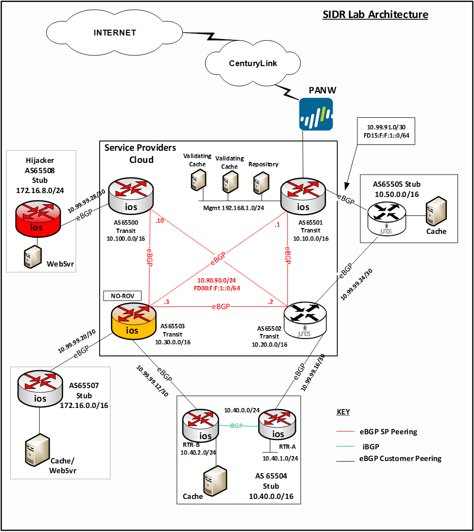
E.2 Requirements
Table E-1 identifies the SIDR functional evaluation requirements that are addressed in this test plan, and their associated test cases.
Table E-1 SIDR Functional Requirements
| Capability Requirement (CR) Identifier (ID) | Parent Requirement | Sub-Requirement 1 | Sub-Requirement 2 | Test Case |
|---|---|---|---|---|
| CR-1 | The SIDR example implementation shall include a capability for BGP routers to perform route origin validation (ROV) on all routes that they receive in BGP update messages. The router will be capable of accurately establishing an initial validation state (valid, invalid, or not found) for a given route and marking the route accordingly. The router will also be capable of accurately re-evaluating that route’s validation state after Resource Public Key Infrastructure (RPKI) test data has been perturbed, re-marking the route (if applicable). | |||
| CR-1.1 | The advertised route is initially evaluated as valid. The single route origin authorization (ROA) that had made the route valid is removed from the RPKI; there is no ROA that covers the route, so the route is re-evaluated as not found. | |||
| CR-1.1.1 | IPv4 address type | SIDR-ROV-1.1.1 | ||
| CR-1.1.2 | IPv6 address type | SIDR-ROV-1.1.2 | ||
| CR-1.2 | The advertised route is initially evaluated as valid. The single ROA that had made the route valid is removed from the RPKI. There is another ROA that covers the route, but the autonomous system number (ASN) in this ROA does not match that of the route’s origin, so the route is re-evaluated as invalid. | |||
| CR-1.2.1 | IPv4 address type | SIDR-ROV-1.2.1 | ||
| CR-1.2.2 | IPv6 address type | SIDR-ROV-1.2.2 | ||
| CR-1.3 | The advertised route is initially evaluated as valid. The single ROA that had made the route valid is removed from the RPKI. There is another ROA that covers the route, but its maximum prefix length is less than the prefix length of the route, so the route is re-evaluated as invalid. | |||
| CR-1.3.1 | IPv4 address type | SIDR-ROV-1.3.1 | ||
| CR-1.3.2 | IPv6 address type | SIDR-ROV-1.3.2 | ||
| CR-1.4 | The advertised route is initially evaluated as valid. An ROA that had made the route valid is removed from the RPKI; there remains another ROA that matches the route, so the route still evaluates as valid. | |||
| CR-1.4.1 | IPv4 address type | SIDR-ROV-1.4.1 | ||
| CR-1.4.2 | IPv6 address type | SIDR-ROV-1.4.2 | ||
| CR-1.5 | The advertised route is initially evaluated as not found. An ROA that matches the route is added to the RPKI, so the route is re-evaluated as valid. | |||
| CR-1.5.1 | IPv4 address type | SIDR-ROV-1.5.1 | ||
| CR-1.5.2 | IPv6 address type | SIDR-ROV-1.5.2 | ||
| CR-1.6 | The advertised route is initially evaluated as not found. An ROA that covers this route, but that has an ASN different from that of the route’s origin, is added to the RPKI, so the route is re-evaluated as invalid. | |||
| CR-1.6.1 | IPv4 address type | SIDR-ROV-1.6.1 | ||
| CR-1.6.2 | IPv6 address type | SIDR-ROV-1.6.2 | ||
| CR-1.7 | The advertised route is initially evaluated as invalid due to an ROA that covers this route, but that has an ASN different from that of the route’s origin. A second ROA that matches this route is added to the RPKI, so the route is re-evaluated as valid. | |||
| CR-1.7.1 | IPv4 address type | SIDR-ROV-1.7.1 | ||
| CR-1.7.2 | IPv6 address type | SIDR-ROV-1.7.2 | ||
| CR-1.8 | The advertised route is initially evaluated as invalid due to the presence of one ROA that covers this route, but that has an ASN different from that of the route’s origin. This is the only ROA that covers the route. It is deleted from the RPKI, so the route is re-evaluated as not found. | |||
| CR-1.8.1 | IPv4 address type | SIDR-ROV-1.8.1 | ||
| CR-1.8.2 | IPv6 address type | SIDR-ROV-1.8.2 | ||
| CR-1.9 | The advertised route is initially evaluated as invalid. There are two ROAs that cover this route, both of which have ASNs different from the route’s origin. Only one of these ROAs is deleted from the RPKI, so the route still evaluates as invalid. | |||
| CR-1.9.1 | IPv4 address type | SIDR-ROV-1.9.1 | ||
| CR-1.9.2 | IPv6 address type | SIDR-ROV-1.9.2 | ||
| CR-1.10 | The advertised route is initially evaluated to be invalid due to the fact that it contains AS_SET, even though there is an ROA that covers the route and that has a maximum length greater than the route’s prefix. A second advertisement is received for this same route that does not contain AS_SET and that is matched by the ROA that is already in the RPKI. The route in this second advertisement is evaluated as valid. | |||
| CR-1.10.1 | IPv4 address type | SIDR-ROV-1.10.1 | ||
| CR-1.10.2 | IPv6 address type | SIDR-ROV-1.10.2 | ||
| CR-2 | The SIDR example implementation shall include a capability for BGP routers to perform ROV on all routes that are redistributed into BGP from another source, such as another protocol or a locally defined static route. The router will be capable of accurately establishing an initial validation state (valid, invalid, or not found) for a given route, marking the route accordingly, and applying appropriate policy depending on the result. The router will also be capable of accurately re-evaluating that route’s validation state after RPKI test data has been perturbed, re-marking the route (if applicable), and applying appropriate policy depending on the (possibly) new result. | |||
| CR-2.1 | A route is redistributed into BGP from a locally defined static route. This route is initially evaluated as valid. The single ROA that had made the route valid is removed from the RPKI. There is another ROA that covers the route, but the ASN in this ROA does not match that of the route’s origin, so the route is re-evaluated as invalid. | |||
| CR-2.1.1 | IPv4 address type | SIDR-ROV-2.1.1 | ||
| CR-2.1.2 | IPv6 address type | SIDR-ROV-2.1.2 | ||
| CR-2.1.3 | IPv4 address type and virtual router instead of physical router | SIDR-ROV-2.1.3 | ||
| CR-2.2 | A route is redistributed into BGP from a locally defined static route. The route is initially evaluated as not found. An ROA that matches the route is added to the RPKI, so the route is re-evaluated as valid. | |||
| CR-2.2.1 | IPv4 address type | SIDR-ROV-2.2.1 | ||
| CR-2.2.2 | IPv6 address type | SIDR-ROV-2.2.2 | ||
| CR-2.3 | A route is redistributed into BGP from a locally defined static route. The advertised route is initially evaluated as not found. An ROA that covers this route, but that has an ASN different from that of the route’s origin, is added to the RPKI, so the route is re-evaluated as invalid. | |||
| CR-2.3.1 | IPv4 address type | SIDR-ROV-2.3.1 | ||
| CR-2.3.2 | IPv6 address type | SIDR-ROV-2.3.2 | ||
| CR-3.1 | A route is redistributed into BGP from an interior gateway protocol (IGP). This route is initially evaluated as valid. The single ROA that had made the route valid is removed from the RPKI; there is no ROA that covers the route, so the route is re-evaluated as not found. | |||
| CR-3.1.1 | IPv4 address type | SIDR-ROV-3.1.1 | ||
| CR-3.2 | A route is redistributed into BGP from an IGP. This route is initially evaluated as invalid due to an ROA that covers this route, but that has an ASN different from that of the route’s origin. A second ROA that matches this route is added to the RPKI, so the route is re-evaluated as valid. | |||
| CR-3.2.1 | IPv4 address type | SIDR-ROV-3.2.1 | ||
| CR-3.3 | A route is redistributed into BGP from an IGP. This route is initially evaluated as invalid due to the presence of one ROA that covers this route, but that has an ASN different from that of the route’s origin. This is the only ROA that covers the route. It is deleted from the RPKI, so the route is re-evaluated as not found. | |||
| CR-3.3.1 | IPv4 address type | SIDR-ROV-3.3.1 | ||
| CR-4 | The SIDR example implementation shall include a capability for BGP routers to be configured with a policy that treats locally defined interior border gateway protocol (iBGP) routes differently from other iBGP routes. In particular, it will be possible to configure router policy such that invalid locally generated iBGP routes and invalid locally defined static routes are not dropped, but other invalid iBGP routes are. | |||
| CR-4.1 | The router under test (RUT) implements its configured policy, which is to retain invalid routes if they are locally generated iBGP routes or locally defined static routes, but to drop all other invalid iBGP routes. | |||
| CR-4.1.1 | IPv4 address type | SIDR-ROV-4.1.1 | ||
| IPv6 address type | SIDR-ROV-4.1.1 | |||
| CR-4.2 | ROV-capable routers can evaluate routes correctly within an iBGP network by using a single, but shared, VC for the iBGP peers, whether the routes are received via an exterior border gateway protocol (eBGP), IGP, static, or from a local network. | |||
| CR-4.2.1 | IPv4 address type with Router A | SIDR-ROV-4.2.1 | ||
| IPv6 address type with Router A | SIDR-ROV-4.2.1 | |||
| CR-4.2.2 | IPv4 address type with Router B | SIDR-ROV-4.2.2 | ||
| IPv6 address type with Router B | SIDR-ROV-4.2.2 | |||
| CR-4.3 | ROV-capable routers can evaluate routes correctly using eBGP, IGP, static, and local network routes within an iBGP network using one shared VC within iBGP peers without Extended Community Strings. | |||
| CR-4.3.1 | IPv4 address type with Router A | SIDR-ROV-4.3.1 | ||
| IPv6 address type with Router A | SIDR-ROV-4.3.1 | |||
| CR-4.3.2 | IPv4 address type with Router B | SIDR-ROV-4.3.2 | ||
| IPv6 address type with Router B | SIDR-ROV-4.3.2 | |||
| CR-4.4 | ROV-capable routers can evaluate routes correctly using eBGP, IGP, static, and local network routes within an iBGP network using one shared VC within iBGP peers with Extended Community Strings. | |||
| CR-4.4.1 | IPv4 address type with Router A | SIDR-ROV-4.4.1 | ||
| IPv6 address type with Router A | SIDR-ROV-4.4.1 | |||
| CR-4.4.2 | IPv4 address type with Router B | SIDR-ROV-4.4.2 | ||
| IPv6 address type with Router B | SIDR-ROV-4.4.2 | |||
| CR-4.5 | ROV-capable routers can evaluate routes correctly using eBGP, IGP, static, and local network routes within an iBGP network using two distinct VCs for the iBGP peers while enabling Extended Community Strings. | |||
| CR-4.5.1 | IPv4 address type with Router A | SIDR-ROV-4.5.1 | ||
| IPv6 address type with Router A | SIDR-ROV-4.5.1 | |||
| CR-4.6 | ROV-capable routers can evaluate routes correctly using eBGP, IGP, static, and local network routes within an iBGP network using two distinct VCs with conflicting records for the iBGP peers while enabling Extended Community String. | |||
| CR-4.6.1 | IPv4 address type with Router A | SIDR-ROV-4.6.1 | ||
| IPv6 address type with Router A | SIDR-ROV-4.6.1 | |||
| CR-5 | The SIDR example implementation shall be capable of applying policies to the ROV-route selection process. | |||
| CR-5.1 | The router can be configured such that invalid routes are discarded and not found routes are installed with a low local preference (LP) value. | |||
| CR-5.1.1 | IPv4 address type | SIDR-ROV-5.1.1 | ||
| IPv6 address type | SIDR-ROV-5.1.1 | |||
| CR-5.1.1 | The router can be configured such that invalid routes are installed with the lowest LP value, valid routes are installed with the highest LP value, and not found routes are installed with an LP value in between. | |||
| CR-5.1.2 | IPv4 address type | SIDR-ROV-5.1.2 | ||
| IPv6 address type | SIDR-ROV-5.1.2 | |||
| CR-6 | The SIDR example implementation shall be capable of having the router and VC synchronize properly such that the correct RPKI information is received at the router following a disruption to the connectivity between a router and its VC. | |||
| CR-6.1 | The router and the VC get re‑synchronized properly after a loss of connectivity. | |||
| CR-6.1.1 | IPv4 address type | SIDR-ROV-6.1.1 | ||
| IPv6 address type | SIDR-ROV-6.1.1 | |||
| CR-6.2 | The router and the VC get re‑synchronized properly after the VC loses power. | |||
| CR-6.2.1 | IPv4 address type | SIDR-ROV-6.2.1 | ||
| IPv6 address type | SIDR-ROV-6.2.1 | |||
| CR-6.3 | The router and the VC get re‑synchronized properly after the router loses power. | |||
| CR-6.3.1 | IPv4 address type | SIDR-ROV-6.3.1 | ||
| IPv6 address type | SIDR-ROV-6.3.1 | |||
| CR-6.4 | The router synchronizes to a different VC after disconnecting from a previous VC. | |||
| CR-6.4.1 | IPv4 address type | SIDR-ROV-6.4.1 | ||
| IPv6 address type | SIDR-ROV-6.4.1 | |||
| CR-6.5 | The router is connected to two VC with identical RPKI information, and then one of those VC is shut down. | |||
| CR-6.5.1 | IPv4 address type | SIDR-ROV-6.5.1 | ||
| IPv6 address type | SIDR-ROV-6.5.1 | |||
| CR-6.6 | The router is connected to two VCs that have different RPKI information, and then one of those VCs is shut down. | |||
| CR-6.6.1 | IPv4 address type | SIDR-ROV-6.6.1 | ||
| IPv6 address type | SIDR-ROV-6.6.1 | |||
| CR-7 | The SIDR example implementation shall include the capability for a resource holder to set up its own delegated certificate authority (CA), create its own repository, and offer a hosted service to its customers, including the ability to publish customer ROAs to its repository, delete customer ROAs from its repository, and have customer ROAs expire from its repository. The ROAs in this delegated CA repository will be included in the RPKI data that relying parties download to their VCs, and validated ROA payloads (VRPs) derived from these ROAs will be provided to relying-party routers via the RPKI-to-router protocol. | |||
| CR-7.1 | A resource holder is able to set up its own delegated CA, create its own repository, create ROAs for the addresses that it holds, and store these ROAs in its own repository. | |||
| CR-7.1.1 | IPv4 address type | SIDR-DM-7.1.1 | ||
| CR-7.2 | A delegated CA is able to create ROAs on behalf of its customers and store them in its repository. | |||
| CR-7.2.1 | IPv4 address type | SIDR-DM-7.2.1 | ||
| CR-7.3 | A delegated CA is able to delete/revoke an ROA, from its own repository, that it has created for addresses that it holds. | |||
| CR-7.3.1 | IPv4 address type | SIDR-DM-7.1.1 | ||
| CR-7.4 | A delegated CA is able to delete/revoke an ROA, from its own repository, that it has created and is storing on behalf of its customers. | |||
| CR-7.4.1 | IPv4 address type | SIDR-DM-7.2.1 | ||
| CR-7.5 | A delegated CA is able to create ROAs, for addresses that it holds, that will expire as designed. | |||
| CR-7.5.1 | IPv4 address type | SIDR-DM-7.1.1 | ||
| CR-7.6 | A delegated CA is able to create ROAs, on behalf of its customers, that will expire as designed. | |||
| CR-7.6.1 | IPv4 address type | SIDR-DM-7.2.1 | ||
| CR-7.7 | ROAs that are stored in the delegated CA’s repository are downloaded to the VCs that relying parties construct, validate, and maintain. | |||
| CR-7.7.1 | IPv4 address type | SIDR-DM-7.1.1 and 7.2.1 | ||
| CR-7.8 | The VRP information that is downloaded by routers from VCs using the RPKI-to-router protocol includes information derived from ROAs that are stored in the delegated CA’s repository. | |||
| CR-7.8.1 | IPv4 address type | SIDR-DM-7.1.1 and 7.2.1 |
E.3 Tests
The remaining subsections provide the tests that have been designed to validate that the SIDR example implementation meets each of the SIDR functional requirements specified in Table E-1 above. Each test consists of multiple fields that collectively identify the objective of the test, the steps required to implement the test, and how to assess the results of the test. Table E-2 provides a template of a test case, including a description of each field in the test case.
Unless otherwise specified, these tests are written under the assumption that the amount of time that elapses between any test step and the next is sufficient to allow modifications that are made to the global RPKI to propagate down to the VC and then to the RUT. This means that if an ROA is updated in one step of the test, then the effects that this ROA has on the validation state of routes in the RUT’s router information base will be evident in the next step of the test.
Table E-2 Test Case Fields
| Test Case Field | Description | ||
|---|---|---|---|
| Test Objective | Lists the requirement being tested (as identified in the table of SIDR functional test requirements). Describes the objective of the test case. | ||
| Preconditions | The starting state of the test case. Preconditions indicate various starting state items, such as a specific capability configuration required or specific protocol and content. | ||
| IPv4 or IPv6? | States which type of addresses are being used. | Test Harness or Hardware with Live RPKI? | Indicates the source of the test data. |
| Test Procedure | The step-by-step actions required to implement the test case. A procedure may consist of a single sequence of steps or multiple sequences of steps (with delineation) to indicate variations in the test procedure. | ||
| Expected Results | The expected results for each variation in the test procedure, assuming that the test functions as intended. | ||
| Actual Results | As expected or the observed results. | ||
| Additional Comments (If Needed) | None. | ||
E.3.1 SIDR ROV Test Cases —Routes Received in BGP Updates
During all harness tests, the RUT communicates the validation result of selected routes to an iBGP peer by using the Extended Community String specified in [RFC 8097]_ or via the regular community string using the type 0x4300 and values 0–2, as specified in [RFC 8097]_, only in 4-octet notation, rather than 8-octet notation. However, visual verification was used with appropriate show commands to verify the expected results with tests performed using hardware with a live RPKI data stream.
The route validation results, as well as the RPKI table within the RUT, will be retrieved and logged. For all tests, the commands used are as follows:
- Cisco:
- To “Verify that this route is installed in the routing table” and “Verify that the RUT evaluates this route advertisement as valid, invalid, or not found,”
use:
show ip bgp. - To “Verify that the RUT receives VRP information,” use:
show ip bgp rpki table.
- To “Verify that this route is installed in the routing table” and “Verify that the RUT evaluates this route advertisement as valid, invalid, or not found,”
use:
- Juniper:
- To “Verify that this route is installed in the routing table” and “Verify that the RUT evaluates this route advertisement as valid, invalid, or not found,”
use:
show table. - To “Verify that the RUT receives VRP information,” use:
show validation database.
- To “Verify that this route is installed in the routing table” and “Verify that the RUT evaluates this route advertisement as valid, invalid, or not found,”
use:
E.3.1.1 Test Case: SIDR-ROV-1.1.1 and 1.1.2
| Test Objective | Test SIDR Requirement CR-1.1. Show that the ROV-capable router correctly evaluates received routes in the following situation: The advertised route is initially evaluated as valid. The single ROA that had made the route valid is removed from the RPKI; there is no ROA that covers the route, so the route is re-evaluated as not found. (valid not found) | ||
| Preconditions | The testbed is configured with the topology and ASNs as depicted in the Testbed Architecture in Figure E-1 and Figure E-2. The router is set up to accept every BGP route, regardless of the validation state. No ROAs have been published that cover 10.100.0.0/16. RUT is Router AS 65501. The following configuration for Router AS65501 has been added: Test 1-1-1 Config.txt | ||
| IPv4 or IPv6? | Both | Test Harness or Hardware with Live RPKI? | Both |
| Test Procedure |
For IPv6, use IP address FD10:100:100:1::/64 in place of 10.100.0.0/16. |
||
| Expected Results | IPv4 Results: Each of the expected results in Steps 3, 4, 5, and 7 above are verified. | ||
| Actual Results | Test completed and functions as intended in Steps 3, 4, 5, and 7. | ||
| Additional Comments (If Needed) | Changes in the validation state of selected routes are also observed via iBGP traffic. Step 5 is observed by monitoring the incoming traffic on its iBGP peer. | ||
Test case SIDR-ROV-1.1.2 is identical to test case SIDR-ROV-1.1.1, except that IPv6 addresses are used instead of IPv4 addresses.
Note: Test case SIDR-ROV-1.1.1 was also completed using the Cisco IOS-XR image running on VMware. Using the same procedures, AS65501 was replaced by this Cisco IOS-XR router with the configuration of the attached file:
E.3.1.2 Test Case: SIDR-ROV-1.2.1 and 1.2.2
| Test Objective | Test SIDR Requirement CR-1.2. Show that the ROV-capable router correctly evaluates received routes in the following situation: The advertised route is initially evaluated as valid. The single ROA that had made the route valid is removed from the RPKI. There is another ROA that covers the route, but the ASN in this ROA does not match that of the route’s origin, so the route is re-evaluated as invalid. (valid invalid) | ||
| Preconditions | The testbed is configured with the topology, IP addressing scheme, and ASNs as depicted in the Testbed Architecture in Figure E-1 and Figure E-2. The router is set up to accept every BGP route, regardless of the validation state. RUT is Router AS65501. The attached file shows the configuration for Router AS65501 that has been added. Test 2-1-1 Config.txt | ||
| IPv4 or IPv6? | Both | Test Harness or Hardware with Live RPKI? | Both |
| Procedure |
For IPv6, use IP address FD10:100:100:1::/64 in place of 10.100.0.0/16. |
||
| Expected Results | Each of the expected results in Steps 4, 5, 6, and 8 above are verified. | ||
| Actual Results | Test completed and functions as intended in Steps 4, 5, 6, and 8. | ||
| Additional Comments (If Needed) | Changes in the validation state of selected routes are also observed via iBGP traffic. Step 6 is validated by monitoring the incoming traffic on its iBGP peer. | ||
Test case SIDR-ROV-1.2.2 is identical to test case SIDR-ROV-1.2.1, except that IPv6 addresses are used instead of IPv4 addresses.
E.3.1.3 Test Case: SIDR-ROV-1.3.1 and 1.3.2
| Test Objective | Test SIDR Requirement CR-1.3.1. Show that the ROV-capable router correctly evaluates received routes in the following situation: The advertised route is initially evaluated as valid. The single ROA that had made the route valid is removed from the RPKI. There is another ROA that covers the route, but its maximum prefix length is less than the prefix length of the route, so the route is re-evaluated as invalid. (valid invalid) | ||
| Preconditions | The testbed is configured with the topology, IP addressing scheme, and ASNs as depicted in the Testbed Architecture in Figure E-1 and Figure E-2. The router is set up to accept every BGP route, regardless of the validation state. | ||
| IPv4 or IPv6? | Both | Test Harness or Hardware with Live RPKI? | Both |
| Procedure |
For IPv6, use IP address FD10:100:100:1::/64 in place of 10.100.0.0/16. |
||
| Expected Results | Each of the expected results in Steps 4, 5, 6, and 8 above are verified. | ||
| Actual Results | Test completed and functions as intended in Steps 4, 5, 6, and 8. | ||
| Additional Comments (If Needed) | Changes in the validation state of selected routes are also observed via iBGP traffic. Step 6 is validated by monitoring the incoming traffic on its iBGP peer. | ||
Test case SIDR-ROV-1.3.2 is identical to test case SIDR-ROV-1.3.1, except that IPv6 addresses are used instead of IPv4 addresses.
E.3.1.4 Test Case: SIDR-ROV-1.4.1 and 1.4.2
| Test Objective | Test SIDR Requirement CR-1.4.1. Show that the ROV-capable router correctly evaluates received routes in the following situation: The advertised route is initially evaluated as valid. An ROA that had made the route valid is removed from the RPKI; there remains another ROA that matches the route, so the route still evaluates as valid. (valid valid) | ||
| Preconditions | The testbed is configured with the topology, IP addressing scheme, and ASNs as depicted in the Testbed Architecture in Figure E-1 and Figure E-2. The router is set up to accept every BGP route, regardless of the validation state. | ||
| IPv4 or IPv6? | Both | Test Harness or Hardware with Live RPKI? | Both |
| Procedure |
For IPv6, use IP address FD10:100:100:1::/64 in place of 10.100.0.0/16. |
||
| Expected Results | Each of the expected results in Steps 4, 5, 6, 8, and 9 above are verified. | ||
| Actual Results | Test completed and functions as intended in Steps 4, 5, 6, 8, and 9. | ||
| Additional Comments (If Needed) | Changes in the validation state of selected routes are also observed via iBGP traffic. Steps 6 and 9 are validated by monitoring the incoming traffic on its iBGP peer. | ||
Test case SIDR-ROV-1.4.2 is identical to test case SIDR-ROV-1.4.1, except that IPv6 addresses are used instead of IPv4 addresses.
E.3.1.5 Test Case: SIDR-ROV-1.5.1 and 1.5.2
| Test Objective | Test SIDR Requirement CR-1.5.1. Show that the ROV-capable router correctly evaluates received routes in the following situation: The advertised route is initially evaluated as not found. An ROA that matches the route is added to the RPKI, so the route is re-evaluated as valid. (not found valid) | ||
| Preconditions | The testbed is configured with the topology, IP addressing scheme, and ASNs as depicted in the Testbed Architecture in Figure E-1 and Figure E-2. The router is set up to accept every BGP route, regardless of the validation state. No ROAs have been published that cover 10.100.0.0/16. | ||
| IPv4 or IPv6? | Both | Test Harness or Hardware with Live RPKI? | Both |
| Procedure |
For IPv6, use IP address FD10:100:100:1::/64 in place of 10.100.0.0/16. |
||
| Expected Results | Each of the expected results in Steps 1, 3, 4, 6, and 7 above are verified. | ||
| Actual Results | Test completed and functions as intended in Steps 1, 3, 4, 6, and 7. | ||
| Additional Comments (If Needed) | Changes in the validation state of selected routes are also observed via iBGP traffic. Steps 1 and 3 are verified combined. Steps 4 and 7 are verified monitoring the incoming traffic via iBGP peer. | ||
Test case SIDR-ROV-1.5.2 is identical to test case SIDR-ROV-1.5.1, except that IPv6 addresses are used instead of IPv4 addresses.
E.3.1.6 Test Case: SIDR-ROV-1.6.1 and 1.6.2
| Test Objective | Test SIDR Requirement CR-1.6.1. Show that the ROV-capable router correctly evaluates received routes in the following situation: The advertised route is initially evaluated as not found. An ROA that covers this route, but that has an ASN different from that of the route’s origin, is added to the RPKI, so the route is re-evaluated as invalid. (not found invalid) | ||
| Preconditions | The testbed is configured with the topology, IP addressing scheme, and ASNs as depicted in the Testbed Architecture in Figure E-1 and Figure E-2. The router is set up to accept every BGP route, regardless of the validation state. No ROAs have been published that cover 10.100.0.0/16. | ||
| IPv4 or IPv6? | Both | Test Harness or Hardware with Live RPKI? | Both |
| Procedure |
For IPv6, use IP address FD10:100:100:1::/64 in place of 10.100.0.0/16. |
||
| Expected Results | Each of the expected results in Steps 1, 3, 4, 6, and 7 above are verified. | ||
| Actual Results | Test completed and functions as intended in Steps 1, 3, 4, 6, and 7. | ||
| Additional Comments (If Needed) | Changes in the validation state of selected routes are also observed via iBGP traffic. Steps 1 and 3 are verified combined. Steps 4 and 7 are verified monitoring the incoming traffic via iBGP peer. | ||
Test case SIDR-ROV-1.6.2 is identical to test case SIDR-ROV-1.6.1, except that IPv6 addresses are used instead of IPv4 addresses.
E.3.1.7 Test Case: SIDR-ROV-1.7.1 and 1.7.2
| Test Description | Test SIDR Requirement CR-1.7.1. Show that the ROV-capable router correctly evaluates received routes in the following situation: The advertised route is initially evaluated as invalid due to an ROA that covers this route, but that has an ASN different from that of the route’s origin. A second ROA that matches this route is added to the RPKI, so the route is re-evaluated as valid. (invalid valid) | ||
| Preconditions | The testbed is configured with the topology, IP addressing scheme, and ASNs as depicted in the Testbed Architecture in Figure E-1 and Figure E-2. The router is set up to accept every BGP route, regardless of the validation state. | ||
| IPv4 or IPv6? | Both | Test Harness or Hardware with Live RPKI? | Both |
| Procedure |
For IPv6, use IP address FD10:100:100:1::/64 in place of 10.100.0.0/16. |
||
| Expected Results | Each of the expected results in Steps 3, 4, 5, 7, and 8 above are verified. | ||
| Actual Results | Test completed and functions as intended in Steps 3, 4, 5, 7, and 8. | ||
| Additional Comments (If Needed) | Changes in the validation state of selected routes are also observed via iBGP traffic. Steps 5 and 8 are verified monitoring the incoming traffic via iBGP peer. | ||
Test case SIDR-ROV-1.7.2 is identical to test case SIDR-ROV-1.7.1, except that IPv6 addresses are used instead of IPv4 addresses.
E.3.1.8 Test Case: SIDR-ROV-1.8.1 and 1.8.2
| Test Objective | Test SIDR Requirement CR-1.8.1. Show that the ROV-capable router correctly evaluates received routes in the following situation: The advertised route is initially evaluated as invalid due to the presence of one ROA that covers this route, but that has an ASN different from that of the route’s origin. This is the only ROA that covers the route. It is deleted from the RPKI, so the route is re-evaluated as not found. (invalid not found) | ||
| Preconditions | The testbed is configured with the topology, IP addressing scheme, and ASNs as depicted in the Testbed Architecture in Figure E-1 and Figure E-2. The router is set up to accept every BGP route, regardless of the validation state. No ROAs have been published that cover 10.100.0.0/16. | ||
| IPv4 or IPv6? | Both | Test Harness or Hardware with Live RPKI? | Both |
| Procedure |
For IPv6, use IP address FD10:100:100:1::/64 in place of 10.100.0.0/16. |
||
| Expected Results | Each of the expected results in Steps 3, 4, 5, 7, and 8 above are verified. | ||
| Actual Results | Test completed and functions as intended in Steps 3, 4, 5, 7, and 8. | ||
| Additional Comments (If Needed) | Changes in the validation state of selected routes are also observed via iBGP traffic. Steps 5 and 8 are verified monitoring the incoming traffic via iBGP peer. | ||
Test case SIDR-ROV-1.8.2 is identical to test case SIDR-ROV-1.8.1, except that IPv6 addresses are used instead of IPv4 addresses.
E.3.1.9 Test Case: SIDR-ROV-1.9.1 and 1.9.2
| Test Objective | Test SIDR Requirement CR-1.9.1. Show that the ROV-capable router correctly evaluates received routes in the following situation: The advertised route is initially evaluated as invalid. There are two ROAs that cover this route, both of which have ASNs different from that of the route’s origin. Only one of these ROAs is deleted from the RPKI, so the route still evaluates as invalid. (invalid invalid) | ||
| Preconditions | The testbed is configured with the topology, IP addressing scheme, and ASNs as depicted in the Testbed Architecture in Figure E-1 and Figure E-2. The router is set up to accept every BGP route, regardless of the validation state. | ||
| IPv4 or IPv6? | Both | Test Harness or Hardware with Live RPKI? | Both |
| Procedure |
For IPv6, use IP address FD10:100:100:1::/64 in place of 10.100.0.0/16. |
||
| Expected Results | Each of the expected results in Steps 4, 5, 6, 8, and 9 above are verified. | ||
| Actual Results | Test completed and functions as intended in Steps 4, 5, 6, 8, and 9. | ||
| Additional Comments (If Needed) | Changes in the validation state of selected routes are also observed via iBGP traffic. Steps 6 and 9 are verified monitoring the incoming traffic via iBGP peer. | ||
Test case SIDR-ROV-1.9.2 is identical to test case SIDR-ROV-1.9.1, except that IPv6 addresses are used instead of IPv4 addresses.
E.3.1.10 Test Case: SIDR-ROV-1.10.1 and 1.10.2
| Test Objective | Test SIDR Requirement CR-1.4.1. Show that the ROV-capable router correctly evaluates received routes in the following situation: The advertised route is initially evaluated to be invalid due to the fact that it contains AS_SET, even though there is an ROA that covers the route and that has a maximum length greater than the route’s prefix. The route is re-announced, this time without the AS_SET in the path. The route in the second advertisement is evaluated as valid. (invalid valid) | ||
| Preconditions | The testbed is configured with the topology, IP addressing scheme, and ASNs as depicted in the Testbed Architecture in Figure E-1 and Figure E-2. The router is set up to accept every BGP route, regardless of the validation state. The following configuration for Routers AS65501, AS65504, AS65507, and AS65511 has been added: Test 1-10-1.txt | ||
| IPv4 or IPv6? | Both | Test Harness or Hardware with Live RPKI? | Both |
| Procedure |
For IPv6, use IP address FD40:40:40:40::68/64, FD60:6060:6060:60::1/64, FD10:100:100:1::1/64. |
||
| Expected Results | Each of the expected results in Steps 6, 7, 10, and 11 above are verified. | ||
| Actual Results | In a few cases, Step 6 did not have the expected result. We found that, in some implementations, the aggregated route/prefix 10.0.0.0/8, 65511 (65504, 65507) was evaluated as not found instead of invalid, as stipulated in [RFC 8210]. |
||
| Additional Comments (If Needed) | Most commercially provided platforms did validate routes containing AS_SET as not found, whether covering ROAs exist or not. | ||
Test case SIDR-ROV-1.10.2 is identical to test case SIDR-ROV-1.10.1, except that IPv6 addresses are used instead of IPv4 addresses.
E.3.2 SIDR ROV Test Cases – Local Static Routes Redistributed into BGP
E.3.2.1 Test Case: SIDR-ROV-2.1.1, 2.1.2, and 2.1.3
| Test Objective | Test SIDR Requirement CR-2.1.1. Show that the ROV-capable router correctly evaluates received routes in the following situation: A route is redistributed into BGP from a locally defined static route. This route is initially evaluated as valid. The single ROA that had made the route valid is removed from the RPKI. There is another ROA that covers the route, but the ASN in this ROA does not match that of the route’s origin, so the route is re-evaluated as invalid. (valid invalid) (This test case is analogous to test case SIDR-ROV-1.2.1, but this test case evaluates a route that has been redistributed into BGP from a static route, rather than a route that was received as a BGP update.) |
||
| Preconditions | The testbed is configured with the topology, IP addressing scheme, and ASNs as depicted in the Testbed Architecture in Figure E-2. The router is set up to accept every BGP route, regardless of the validation state. No ROAs have been published that cover 10.10.0.0/16. The following configuration for Router AS65501 has been added: Test 2-1-1 Config.txt | ||
| IPv4 or IPv6? | Both | Test Harness or Hardware with Live RPKI? | Hardware with Live RPKI |
| Procedure |
For IPv6, use IP address FD10:10:10:10::/64 in place of 10.10.0.0/16. |
||
| Expected Results | Each of the expected results in Steps 5, 6, 8, and 9 above are verified. | ||
| Actual Results | Test completed and functions as expected. | ||
| Additional Comments (If Needed) | We noticed that, while some vendors’ implementation evaluates local routes (e.g., prefixes learned from static, IGP, and connected routes) as valid, others assess the same routes as unverified. | ||
Test case SIDR-ROV-2.1.2 is identical to test case SIDR-ROV-2.1.1, except that IPv6 addresses are used instead of IPv4 addresses. The following configuration for Routers AS65501 and AS65505 was added prior to running the test: Test 2-1-1B Config.txt
Test case SIDR-ROV-2.1.3 is identical to test case SIDR-ROV-2.1.1, except that the Cisco IOS XR virtual router was used instead of the Cisco 7206 physical router. The following configuration for the Cisco IOS XR virtual router was added prior to running the test: Test 2-1-1 XR Config.txt
E.3.2.2 Test Case: SIDR-ROV-2.2.1 and 2.2.2
| Test Objective | Test SIDR Requirement CR-2.2.1. Show that the ROV-capable router correctly evaluates received routes in the following situation: A route is redistributed into BGP from a locally defined static route. This route is initially evaluated as not found. An ROA that matches the route is added to the RPKI, so the route is re-evaluated as valid. (not found valid) (This test case is analogous to test case SIDR-ROV-1.5.1, but this test case evaluates a route that has been redistributed into BGP from a static route, rather than a route that was received as a BGP update.) |
||
| Preconditions | The testbed is configured with the topology, IP addressing scheme, and ASNs as depicted in the Testbed Architecture in Figure E-1. The router is set up to accept every BGP route, regardless of the validation state. No ROAs have been published that cover the route 10.10.1.0/16. The following configuration for Routers AS65501 and AS65505 has been added: Test 2-2-1 Config.txt | ||
| IPv4 or IPv6? | Both | Test Harness or Hardware with Live RPKI? | Hardware with Live RPKI |
| Procedure |
For IPv6, use IP address FD10:10:10:10::/64 in place of 10.10.0.0/16. |
||
| Expected Results | Each of the expected results in Steps 4, 5, 7, and 8 above are verified. | ||
| Actual Results | Test completed and functions as expected. | ||
| Additional Comments (If Needed) | None | ||
Test case SIDR-ROV-2.2.2 is identical to test case SIDR-ROV-2.2.1, except that IPv6 addresses are used instead of IPv4 addresses. The following configuration for Router AS65505 was updated prior to running the test: Test 2-2-1B Config.txt
E.3.2.3 Test Case: SIDR-ROV-2.3.1 and 2.3.2
| Test Objective | Test SIDR Requirement CR-2.3.1. Show that the ROV-capable router correctly evaluates received routes in the following situation: A route is redistributed into BGP from a locally defined static route. This route is initially evaluated as not found. An ROA that covers this route, but that has an ASN different from that of the route’s origin, is added to the RPKI, so the route is re-evaluated as invalid. (not found invalid) (This test case is analogous to test case SIDR-ROV-1.6.1, but this test case evaluates a route that has been redistributed into BGP from a static route, rather than a route that was received as a BGP update.) |
||||
| Preconditions | The testbed is configured with the topology, IP addressing scheme, and ASNs as depicted in the Testbed Architecture in Figure E-1 and Figure E-2. The router is set up to accept every BGP route, regardless of the validation state. No ROAs have been published that cover the route 10.10.1.0/16. The following configuration for Routers AS65501 and AS65505 has been added: Test 2-3-1 Config.txt | ||||
| IPv4 or IPv6? | Both | Test Harness or Hardware with Live RPKI? | Both | ||
| Procedure |
For IPv6, use IP address FD10:10:10:10::/64 in place of 10.10.0.0/16. |
||||
| Expected Results | Each of the expected results in Steps 4, 5, 7, and 8 above are verified. | ||||
| Actual Results | Test completed and functions as expected. | ||||
| Additional Comments (If Needed) | None | ||||
Test case SIDR-ROV-2.3.2 is identical to test case SIDR-ROV-2.3.1, except that IPv6 addresses are used instead of IPv4 addresses. The following configuration for Router AS65505 was updated prior to running the test: Test 2-3-1B Config.txt
E.3.3 SIDR ROV Test Cases — Routes Redistributed into BGP from an IGP
E.3.3.1 Test Case: SIDR-ROV-3.1.1
| Test Objective | Test SIDR Requirement CR-3.1.1. Show that the ROV-capable router correctly evaluates received routes in the following situation: A route is redistributed into BGP from an IGP. This route is initially evaluated as valid. The single ROA that had made the route valid is removed from the RPKI; there is no ROA that covers the route, so the route is re-evaluated as not found. (valid not found) (This test case is analogous to test case SIDR-ROV-1.1.1, but this test case evaluates a route that has been redistributed into BGP from an IGP, rather than a route that was received as a BGP update.) |
||
| Preconditions | The testbed is configured with the topology, IP addressing scheme, and ASNs as depicted in the Testbed Architecture in Figure E-1 and Figure E-2. The router is set up to accept every BGP route, regardless of the validation state. No ROAs have been published that cover the route 10.10.0.0/16. The following configuration for Routers AS65501 and AS65505 has been added: Test 3-1-1 Config.txt | ||
| IPv4 or IPv6? | IPv4 | Test Harness or Hardware with Live RPKI? | Both |
| Procedure |
For IPv6, use IP address FD10:10:10:10::/64 in place of 10.10.0.0/16. |
||
| Expected Results | Each of the expected results in Steps 4, 5, 7, and 8 above are verified. | ||
| Actual Results | Test completed and functions as expected. | ||
| Additional Comments (If Needed) | None | ||
E.3.3.2 Test Case: SIDR-ROV-3.2.1
| Test Objective | Test SIDR Requirement CR-3.2.1. Show that the ROV-capable router correctly evaluates received routes in the following situation: A route is redistributed into BGP from an IGP. This route is initially evaluated as invalid due to an ROA that covers this route, but that has an ASN different from that of the route’s origin. A second ROA that matches this route is added to the RPKI, so the route is re-evaluated as valid. (invalid valid) (This test case is analogous to test case SIDR-ROV-1.7.1, but this test case evaluates a route that has been redistributed into BGP from an IGP, rather than a route that was received as a BGP update.) |
||
| Preconditions | The testbed is configured with the topology, IP addressing scheme, and ASNs as depicted in the Testbed Architecture in Figure E-1 and Figure E-2. The router is set up to accept every BGP route, regardless of the validation state. The following configuration for Routers AS65501 and AS65505 has been added: Test 3-2-1 Config.txt | ||
| IPv4 or IPv6? | IPv4 | Test Harness or Hardware with Live RPKI? | Both |
| Procedure |
For IPv6, use IP address FD10:10:10:10::/64 in place of 10.10.0.0/16. |
||
| Expected Results | Each of the expected results in Steps 4, 5, 7, and 8 above are verified. | ||
| Actual Results | Test completed and functions as expected. | ||
| Additional Comments (If Needed) | None | ||
E.3.3.3 Test Case: SIDR-ROV-3.3.1
| Test Objective | Test SIDR Requirement CR-3.3.1. Show that the ROV-capable router correctly evaluates received routes in the following situation: A route is redistributed into BGP from an IGP. This route is initially evaluated as invalid due to the presence of one ROA that covers this route, but that has an ASN different from that of the route’s origin. This is the only ROA that covers the route. It is deleted from the RPKI, so the route is re-evaluated as not found. (invalid not found) (This test case is analogous to test case SIDR-ROV-1.8.1, but this test case evaluates a route that has been redistributed into BGP from an IGP, rather than a route that was received as a BGP update.) |
||
| Preconditions | The testbed is configured with the topology, IP addressing scheme, and ASNs as depicted in the Testbed Architecture in Figure E-1 and Figure E-2. The router is set up to accept every BGP route, regardless of the validation state. No ROAs have been published that cover 10.10.0.0/16. The following configuration for Routers AS65501 and AS65505 has been added: Test 3-3-1 Config.txt | ||
| IPv4 or IPv6? | IPv4 | Test Harness or Hardware with Live RPKI? | Both |
| Procedure |
For IPv6, use IP address FD10:10:10:10::/64 in place of 10.10.0.0/16. |
||
| Expected Results | Each of the expected results in Steps 4, 5, 7, and 8 above are verified. | ||
| Actual Results | Test completed and functions as expected. | ||
| Additional Comments (If Needed) | None | ||
E.3.4 iBGP Testing
E.3.4.1 Test Case: SIDR-ROV-4.1.1
| Test Objective | Test SIDR Requirement CR-4.1. Show that the ROV-capable router correctly implements its policy to treat locally defined iBGP routes differently from other iBGP routes. In particular, show that the router can be configured to drop invalid routes, unless the route is a locally generated iBGP or a locally defined static route. Define two route prefixes in iBGP: Prefix A, which is locally generated, and Prefix B, which is not. Define Prefix C, which is an eBGP route. Define a static route, D. Ensure that all four routes will be evaluated and marked as invalid due to having exactly one ROA that covers each route, but that ROA has an ASN different from that of the route’s origin. Configure routing policy such that Prefixes A and D (which are locally generated) will not be dropped. Validate that Prefixes A and D are inserted into the routing table, whereas Prefixes B and C are not. This test case is similar to test case SIDR-ROV-2.3.1, but, in this test case, the invalid non-locally defined static route that evaluates as invalid is dropped. It is also similar to test case SIDR-ROV-2.5.1, but, in this test case, the invalid non‑locally generated iBGP route that evaluates as invalid is dropped. |
||
| Preconditions | The testbed is configured with the topology, IP addressing scheme, and ASNs as depicted in the Testbed Architecture in Figure E-2. The RUT is configured with a policy of discarding invalid routes unless those invalid routes are locally generated iBGP or locally defined static routes. There is at least one iBGP route that is not locally generated. The following configuration for Routers AS65501 and AS65501i has been added: Test 4-1-1 Config.txt | ||
| IPv4 or IPv6? | Both | Test Harness or Hardware with Live RPKI? | Hardware with Live RPKI |
| Procedure |
For IPv6, use FD10:10:10:10::/64, FD20:20:20:1::1/64, FD30:30:30:1::1/64, FD40:40:40:1::1/64. |
||
| Expected Results | Each of the expected results in Steps 3, 9, 10, and 11 above are verified. | ||
| Actual Results | Vendor implementation varies. Certain vendors present all local routes and prefixes as valid, while others show them as unverified. | ||
| Additional Comments (If Needed) | Whereas [RFC 6810] stipulates that routes or prefixes learned locally (IGP, static and connected) should be designated as not found, vendor implementation variables interpret them as either unverified or valid. | ||
E.3.4.2 Test Case: SIDR-ROV-4.2.1
| Test Objective | Examine RPKI validation by using eBGP, IGP, static, and local network routes within an iBGP network by using a single, but shared, VC within the iBGP peers. | ||
| Preconditions | The testbed is configured with the topology, IP addressing scheme, and ASNs as depicted in the Testbed Architecture in Figure E-2. AS 65511 is connected to AS 65501, and AS 65501 consists of two routers speaking iBGP. The edge router is connected to AS 65511 via eBGP and labeled AS65501-R1-1 and the iBGP peer AS65501i-R1-2. The RPKI VC 1 contains all used IP prefixes (10.10.0.0/16, 10.20.0.0/16, 10.30.0.0/16, and 10.40.0.0/16), but is assigned to origin AS 65509. The outcome should result in invalid based on the validation algorithm. Note: All routers are configured to NOT drop invalid. Traffic A: 10.20.0.0/16 is a route originated by AS 65511. Traffic B: There are three routes: one learned via IGP (10.30.0.0/16), another via static (10.10.0.0/16), and the third via local (10.40.0.0/16) network. AS65501-R1-1: Configure connection to RPKI VC 1, NO Extended Community String. AS65501i-R1-2: Configure router as plain BGP (no RPKI). The following configuration for Routers AS65501 and AS65501i was added: Test 4-2-1 Config.txt |
||
| IPv4 or IPv6? | Both | Test Harness or Hardware with Live RPKI? | Hardware with Live RPKI |
| Procedure |
For IPv6, use FD10:10:10:10::/64, FD20:20:20:1::1/64, FD30:30:30:1::1/64, FD40:40:40:1::1/64. |
||
| Expected Results | Each of the expected results in Steps 3, 4, 5, 6, 8, and 9 above are verified. | ||
| Actual Results | Vendor implementation varies. Certain vendors present all local routes and prefixes as valid, while others show them as unverified. | ||
| Additional Comments (If Needed) | Whereas [RFC 6810] stipulates that routes or prefixes learned locally (IGP, static, and connected) should be designated as not found, vendor implementation variable interprets them as either unverified or valid. | ||
Test case SIDR-ROV-4.2.2 is identical to test case SIDR-ROV-4.2.1, except that a Juniper router was used instead of a Cisco router for Router AS65501i. The following configuration for Routers AS65501 and AS65501i was updated prior to running the test: Test 4-2-1 Juniper Config.txt
E.3.4.3 Test Case: SIDR-ROV-4.3.1
| Test Objective | Examine RPKI validation by using eBGP, IGP, static, and local network routes within an iBGP network using one shared VC within the iBGP peers without the Extended Community Strings configuration. | ||
| Preconditions | The testbed is configured with the topology, IP addressing scheme, and ASNs as depicted in the Testbed Architecture in Figure E-2. AS 65511 is connected to AS 65501, and AS 65501 consists of two routers speaking iBGP. The edge router is connected to AS 65511 via eBGP and labeled as AS65501-R1-1, and the iBGP peer labeled as. AS65501i-R1-2. The RPKI VC 1 contains all used IP prefixes (10.10.0.0/16, 10.20.0.0/16, 10.30.0.0/16, and 10.40.0.0/16), but is assigned to origin AS 65509. The outcome should result in invalid based on the validation algorithm. All routers are configured to NOT drop invalid. Traffic A is a route originated by AS 65501. Traffic B has three routes: one learned via IBGP network, one via static network, and one via local network. R1-1: Configure connection to RPKI VC 1, NO Extended Community String. R1-2: Configure connection to RPKI VC 1. The following configuration for Routers AS65501 and AS65501i was added: Test 4-3-1 Config.txt |
||
| IPv4 or IPv6? | Both | Test Harness or Hardware with Live RPKI? | Hardware with Live RPKI |
| Procedure |
For IPv6, use FD10:10:10:10::/64, FD20:20:20:1::1/64, FD30:30:30:1::1/64, FD40:40:40:1::1/64. |
||
| Expected Results | Each of the expected results in Steps 3, 4, 5, 6, and 8 above are verified. | ||
| Actual Results | Vendor implementation varies. Certain vendors present all local routes and prefixes as valid, while others show them as unverified. | ||
| Additional Comments (If Needed) | Whereas [RFC 6810] stipulates that routes or prefixes learned locally (IGP, static, and connected) should be designated as not found, vendor implementation differ and designate them as either unverified or valid. | ||
Test case SIDR-ROV-4.3.2 is identical to test case SIDR-ROV-4.3.1, except that a Juniper router was used instead of a Cisco router for Router AS65501i. The following configuration for Routers AS65501 and AS65501i was updated prior to running the test: Test 4-3-1 Juniper Config.txt
E.3.4.4 Test Case: SIDR-ROV-4.4.1
| Test Objective | Examine RPKI validation by using eBGP, IGP, static, and local network routes within an iBGP network using one shared VC within the iBGP peers. (With Extended Community Strings) | ||
| Preconditions | The testbed is configured with the topology, IP addressing scheme, and ASNs as depicted in the Testbed Architecture in Figure E-2. AS 65511 is connected to AS 65501, and AS 65501 consists of two routers speaking iBGP. The edge router is connected to AS 65511 via eBGP and labeled AS65501-R1-1 and the iBGP peer as AS65501i-R1-2. The RPKI VC 1 contains all used IP prefixes (10.10.0.0/16, 10.20.0.0/16, 10.30.0.0/16, and 10.40.0.0/16) but is assigned to origin AS 65509. The outcome should result in invalid based on the validation algorithm. All routers are configured to NOT drop invalid. Traffic A is a route originated by AS 65501. Traffic B has three routes: one learned via IBGP network, one via static network, and one via local network. R1-1: Configure connection to RPKI VC 1, enable Extended Community String. R1-2: Configure router as plain BGP (no RPKI). The following configuration for Routers AS65501 and AS65501i was added: Test 4-4-1 Config.txt |
||
| IPv4 or IPv6? | Both | Test Harness or Hardware with Live RPKI? | Hardware with Live RPKI |
| Procedure |
For IPv6, use FD10:10:10:10::/64, FD20:20:20:1::1/64, FD30:30:30:1::1/64, FD40:40:40:1::1/64. |
||
| Expected Results | Each of the expected results in Steps 3, 4, 5, 6, 8, and 9 above are verified. | ||
| Actual Results | Vendor implementation varies. Certain vendors present all local routes and prefixes as valid, while others show them as unverified. | ||
| Additional Comments (If Needed) | Whereas [RFC 6810] stipulates that routes or prefixes learned locally (IGP, static, and connected) should be designated as not found, vendor implementation differ and designate them as either unverified or valid. | ||
Test case SIDR-ROV-4.4.2 is identical to test case SIDR-ROV-4.4.1, except that a Juniper router was used instead of a Cisco router for Router AS65501i. The following configuration for Router AS65501i was updated prior to running the test: Test 4-4-1 Juniper Config.txt
E.3.4.5 Test Case: SIDR-ROV-4.5.1
| Test Objective | Examine RPKI validation by using eBGP, IGB, static, and local network routes within an iBGP network using two distinct VCs (VCs 1 and 2) within the iBGP peers while enabling Extended Community String. | ||
| Preconditions | The testbed is configured with the topology, IP addressing scheme, and ASNs as depicted in the Testbed Architecture in Figure E-2. AS 65511 is connected to AS 65501, and AS 65501 consists of two routers speaking iBGP. The edge router connected to AS 65511 is labeled R1-1, and the iBGP peer to AS65501-R1-1 is labeled AS65501i-R1-2. The RPKI VC 1 contains all used IP prefixes, but for origin 65509. The RPKI VC 2 contains all used IP prefixes of Traffic A with origin 65511, and IP prefixes of Traffic B with origin 65501. VC 1 should result in invalid for all routes in R1-1, and VC 2 will result in valid for all routes in R1-2 if validated using the RPKI validation algorithm. All routers are configured to NOT drop invalid. Traffic A is a route originated by AS 65511. Traffic B has three routes: one learned via IBGP network, one via static network, and one via local network. R1-1: Configure the connection to RPKI VC 1 and enable Extended Community String. R1-2: Configure the connection to RPKI VC 2 and enable Extended Community String. The following configuration for Routers AS65501 and AS65501i has been added: Test 4-5-1 Config.txt |
||
| IPv4 or IPv6? | Both | Test Harness or Hardware with Live RPKI? | Hardware with Live RPKI |
| Procedure |
For IPv6, use FD10:10:10:10::/64, FD20:20:20:1::/64, FD30:30:30:1::/64, FD40:40:40:1::/64. |
||
| Expected Results | Each of the expected results in Steps 3, 4, 5, 6, 8, and 9 above will be verified. | ||
| Actual Results | Vendor implementation varies. Certain vendors present all local routes and prefixes as valid, while others show them as unverified. | ||
| Additional Comments (If Needed) | Whereas [RFC 6810] stipulates that routes or prefixes learned locally (IGP, static, and connected) should be designated as not found, vendor implementation differ and designate them as either unverified or valid. | ||
E.3.4.6 Test Case: SIDR-ROV-4.6.1
| Test Objective | Examine RPKI validation by using eBGP, IGP, static, and local network routes within an iBGP network using two distinct VCs with conflicting records within the iBGP peers while enabling Extended Community String. Verify the validation state of the RUT. | ||
| Preconditions | The testbed is configured with the topology, IP addressing scheme, and ASNs as depicted in the Testbed Architecture in Figure E-2. AS 65511 is connected to AS 65501, and AS 65501 consists of two routers speaking iBGP. The edge router connected to AS 65511 is labeled R1-1, and the iBGP peer to AS65501-R1-1 is labeled AS65501i-R1-2. The RPKI VC 1 contains all used IP prefixes, except for origin 65509. The RPKI VC 2 contains all used IP prefixes of Traffic A with origin 65511, and IP prefixes of Traffic B with origin 65501. VC 1 should result in invalid for all routes in R1-1, and VC 2 will result in valid for all routes in R1-2, if validated using the RPKI validation algorithm. All routers are configured to NOT drop invalid. Traffic A is a route originated by AS 65511. Traffic B has three routes: one learned via IGP, one via static network, and one via local network. R1-1: Configure the connection to RPKI VC 1 and enable Extended Community String. R1-2: Configure the connection to RPKI VC 2 and enable Extended Community String. The following configuration for Routers AS65501 and AS65501i has been added: Test 4-6-1 Config.txt |
||
| IPv4 or IPv6? | Both | Test Harness or Hardware with Live RPKI? | Hardware with Live RPKI |
| Procedure |
For IPv6, use FD10:10:10:10::/64, FD20:20:20:1::/64, FD30:30:30:1::/64, FD40:40:40:1::/64. |
||
| Expected Results | Each of the expected results in Steps 3, 4, 5, 6, 8, and 9 above will be verified. | ||
| Actual Results | Vendor implementation varies. Certain vendors present all local routes and prefixes as valid, while others show them as unverified. | ||
| Additional Comments (If Needed) | Whereas [RFC 6810] stipulates that routes or prefixes learned locally (IGP, static, and connected) should be designated as not found, vendor implementation differ and designate them as either unverified or valid. | ||
E.3.5 Applying Policies to ROV – Route Selection Process
E.3.5.1 Test Case: SIDR-ROV-5.1.1
| Test Objective | RUT: If the route is invalid, discard the route; if the route is not found, install the route with a low local preference (LP) value. | ||
| Preconditions | The testbed is configured with the topology, IP addressing scheme, and ASNs as depicted in the Testbed Architecture in Figure E-1 and Figure E-2. | ||
| IPv4 or IPv6? | Both | Test Harness or Hardware with Live RPKI? | Both |
| Procedure |
For IPv6, use FD10:10:10:0::/64, FD20:20:20::/64, FD30:30:30::/64, FD40:40:40::/64. |
||
| Expected Results | Invalid routes will be discarded. Not found routes will have an LP of 90. Valid routes will be inserted in the routing table with a default LP. |
||
| Actual Results | All implemented polices performed as expected. | ||
| Additional Comments (If Needed) | Note that one vendor (e.g., Cisco) discards invalid routes by default, while another vendor leaves the decision to discard to its customer. | ||
E.3.5.2 Test Case: SIDR-ROV-5.1.2
| Test Objective | RUT: Allow the installation of invalid routes and configure policies such that: If the route is invalid, install the route with LP=70. If the route is not found, install the route with LP=80. If the route is valid, install the route with LP=110. |
||
| Preconditions | The testbed is configured with the topology, IP addressing scheme, and ASNs as depicted in the Testbed Architecture in Figure E-1 and Figure E-2. | ||
| IPv4 or IPv6? | Both | Test Harness or Hardware with Live RPKI? | Both |
| Procedure |
For IPv6, use FD10:10:10:0::/64, FD20:20:20::/64, FD30:30:30::/64, FD40:40:40::/64. |
||
| Expected Results | Invalid routes with LP=70 Not found routes with LP=80 Valid routes with LP=110 |
||
| Actual Results | All implemented policies performed as expected. | ||
| Additional Comments (If Needed) | Note that one vendor (e.g., Cisco) discards invalid routes by default, while another vendor leaves the decision to discard to its customer. | ||
E.3.6 Router Cache Synchronization
E.3.6.1 Test Case: SIDR-ROV-6.1.1
| Test Objective | Test SIDR Requirements CR-6.1.1, when working with IPv4/6 addresses. Show that the RUT receives and installs VRPs into the RPKI database properly after a loss of connectivity to the RPKI validator. | ||
| Preconditions | The testbed is configured with the topology, IP addressing scheme, and ASNs as depicted in the Testbed Architecture in Figure E-1 and Figure E-2. The RUT’s VC is empty, and the RPKI validator/cache is empty. The following configuration for the Cisco IOS XR router is used as the baseline for this test: Test 6-1-1 Config.txt |
||
| IPv4 or IPv6? | Both | Test Harness or Hardware with Live RPKI? | Both |
| Procedure |
|
||
| Expected Results | Each of the expected results in Steps 1, 3, and 8 above will be verified. | ||
| Actual Results | The test completed and the functions were as intended in Steps 1, 3, and 8. | ||
| Additional Comments (If Needed) | The TCP connection was disrupted by shutting down the TCP interface. After reenabling the interface, a new TCP session was established. | ||
E.3.6.2 Test Case: SIDR-ROV-6.2.1
| Test Objective | Test SIDR Requirements CR-6.2.1 when working with IPv4/6 addresses. Show that the RUT and the RPKI validator function properly when the RPKI validator loses power, causing it to lose state. | ||
| Preconditions | The testbed is configured with the topology, IP addressing scheme, and ASNs as depicted in the Testbed Architecture in Figure E-1 and Figure E-2. The RUT’s cache is empty, and the RPKI validator/cache is empty. The following configuration for the Cisco IOS XR router is used as the baseline for this test: Test 6-2-1 Config.txt |
||
| IPv4 or IPv6? | Both | Test Harness or Hardware with Live RPKI? | Both |
| Procedure |
|
||
| Expected Results | Each of the expected results in Steps 1, 3, and 6 above will be verified. | ||
| Actual Results | The test was completed, and the functions were as intended in Steps 1, 3, and 6, but only if the VC presented a new session ID [RFC 6810] for the newly created session. | ||
| Additional Comments (If Needed) | In cases where the cache presented the router erroneously with a re-used session ID, not all router implementations cleared the previous validation state correctly and immediately. This problem was resolved, after a configurable time period of one minute up to one hour. | ||
E.3.6.3 Test Case: SIDR-ROV-6.3.1
| Test Objective | Test SIDR Requirements CR-6.3.1 when working with IPv4/6 addresses. Show that the RUT receives and installs VRPs into the RPKI database properly after the RUT experienced a loss of power. | ||
| Preconditions | The testbed is configured with the topology, IP addressing scheme, and ASNs as depicted in the Testbed Architecture in Figure E-1 and Figure E-2. The RUT’s cache is empty, and the RPKI validator/cache is empty. The following configuration for the Cisco IOS XR router is used as the baseline for this test: Test 6-3-1 Config.txt |
||
| IPv4 or IPv6? | Both | Test Harness or Hardware with Live RPKI? | Both |
| Procedure |
|
||
| Expected Results | Each of the expected results in Steps 1, 3, and 8 above will be verified. | ||
| Actual Results | The results were as expected. | ||
| Additional Comments (If Needed) | None | ||
E.3.6.4 Test Case: SIDR-ROV-6.4.1
| Test Objective | Test SIDR Requirements CR-6.4.1 when working with IPv4/6 addresses. Show that the RUT receives and installs VRPs into the RPKI database properly when switching to a cache with a different RPKI state. | ||
| Preconditions | The testbed is configured with the topology, IP addressing scheme, and ASNs as depicted in the Testbed Architecture in Figure E-1 and Figure E-2. The RUT’s cache is empty, and RPKI validator/Caches 1 and 2 are empty. The following configuration for the Cisco IOS XR router is used as the baseline for this test: Test 6-4-1 |
||
| IPv4 or IPv6? | Both | Test Harness or Hardware with Live RPKI? | Both |
| Procedure |
|
||
| Expected Results | Each of the expected results in Steps 1, 3, and 6 above will be verified. | ||
| Actual Results | The results were as expected. | ||
| Additional Comments (If Needed) | This experiment included operator involvement. In our test cases, we did not encounter any issues with the remaining stale data, but, even if we had, clearing the table would resolve the issue. Also, all vendor systems that we used perform a union on the validation databases. Therefore, it will be good practice to add the new cache and retrieve the VRP data prior to removing the old cache, to keep churn in the routing table to a minimum. |
||
E.3.6.5 Test Case: SIDR-ROV-6.5.1
| Test Objective | Test SIDR Requirements CR-6.5.1 when working with IPv4/6 addresses. Show that the RUT receives and installs VRPs of two identical RPKI caches into the RPKI database properly. Then, Cache 1 disappears. | ||
| Preconditions | The testbed is configured with the topology, IP addressing scheme, and ASNs as depicted in the Testbed Architecture in Figure E-1 and Figure E-2. The RUT’s cache is empty, and RPKI validator/Caches 1 and 2 are empty. The following configuration for the Cisco IOS XR router is used as the baseline for this test: Test 6-5-1 Config.txt |
||
| IPv4 or IPv6? | Both | Test Harness or Hardware with Live RPKI? | Both |
| Procedure |
|
||
| Expected Results | Each of the expected results in Steps 1, 4, 6, 8, and 10 above will be verified. | ||
| Actual Results | Results were as expected. | ||
| Additional Comments (If Needed) | The vendor implementations act differently, mainly controlled by their configurations. This means that one implementation identified the loss of the cache faster than the other. We determined that the router that kept data longer cleared stale data after a configured time span between one minute and one hour. | ||
E.3.6.6 Test Case: SIDR-ROV-6.6.1
| Test Objective | Test SIDR Requirements CR-6.6.1 when working with IPv4/6 addresses. Show that the RUT receives and installs VRPs of two RPKI caches with a slightly different view on the RPKI into the RPKI database properly. Then, Cache 1 disappears. | ||
| Preconditions | The testbed is configured with the topology, IP addressing scheme, and ASNs as depicted in the Testbed Architecture in Figure E-1 and Figure E-2. The RUT’s cache is empty, and RPKI validator/Caches 1 and 2 are empty. Test 6-6-1 Config.txt |
||
| IPv4 or IPv6? | Both | Test Harness or Hardware with Live RPKI? | Both |
| Procedure |
|
||
| Expected Results | Each of the expected results in Steps 1, 4, 6, 8, 10, 12, and 13 above will be verified. | ||
| Actual Results | Results were as expected. | ||
| Additional Comments (If Needed) | The vendor implementations act differently, mainly controlled by their configurations. This means that one implementation identified the loss of the cache faster than the other. We determined that the router that kept data longer cleared stale data after a configured time span between one minute and one hour. Also, all router implementations that were tested take a union of the connected caches. |
||
E.3.7 SIDR Delegated Model Test Cases
Test case SIDR-ROV-2.7.2 is identical to test case SIDR-ROV-2.7.1, except that IPv6 addresses are used instead of IPv4 addresses.
The following tests are designed to verify capabilities related to the implementation of a delegated CA.
E.3.7.1 Test Case: SIDR-DM-7.1.1
| Test Objective | Test SIDR Requirements CR-7.1.1 when working with IPv4 addresses. Show that a resource holder can set up its own CA as a delegated RPKI participant and create, store, and manage ROAs for its own addresses in its own repository, and that this ROA information will be downloaded to local VCs and provided to routers that are performing ROV. Furthermore, show that ROAs will be removed from the RPKI upon expiration. (In this test case, a resource holder sets up its own delegated CA and repository and demonstrates the ability to create, manage, and store ROAs for itself. The resource holder demonstrates the ability to create, manage, and store ROAs for its customers.) |
||
| Preconditions | The testbed is configured with the topology, IP addressing scheme, and ASNs as depicted in the Testbed Architecture in Figure E-2.
|
||
| IPv4 or IPv6? | IPv4 | Test Harness or Hardware? | Hardware |
| Procedure |
|
||
| Expected Results | Each of the expected results in Steps 5, 7, 9, 11, 13, 15, 17, 19, and 21 are be verified. | ||
| Actual Results | Unable to complete certain steps. See comments below. | ||
| Additional Comments (If Needed) | Observations (with comments). Steps 6 through 10 cannot be met because the Dragon Research Labs rpki.net toolkit does not permit specifying an expiration date of an EE certificate. According to the creators of the only documented delegated RPKI toolkit, the toolkit was designed under the assumption that all ROAs in the repository should have current EE certificates. If their EE certificate is expired, then it shouldn’t be in the repository. There is debate as to whether this is a sound model. For example, the American Registry for Internet Numbers’ (ARIN’s) hosted RPKI model permits the specification of EE certificate expiration dates. All test procedures are possible, with the exception of the specification of an EE certificate expiration date. |
||
E.3.7.2 Test Case: SIDR-DM-7.2.1
| Test Objective | Test SIDR Requirements CR-7.2.1 when working with IPv4 addresses. Show that a resource holder can set up its own CA as a delegated RPKI participant and create, store, and manage ROAs on behalf of its customers in its own repository, and that this ROA information will be downloaded to local VCs and provided to routers that are performing ROV. Furthermore, show that these ROAs will be removed from the RPKI upon expiration. (In this test case, a resource holder sets up its own delegated CA and repository and demonstrates the ability to create, manage, and store ROAs on behalf of its customers. ) |
||
| Preconditions |
|
||
| IPv4 or IPv6? | IPv4 | Test Harness or Hardware? | Hardware |
| Procedure |
|
||
| Expected Results | Each of the expected results in Steps 4, 6, 8, 10, 12, and 14 above will be verified. | ||
| Actual Results | Unable to complete certain steps. See the comments below. | ||
| Additional Comments (If Needed) | Observations (with comments). Similar to Appendix E.3.7.1, Steps 6 through 10 cannot be met because the Dragon Research Labs rpki.net toolkit does not permit specifying an expiration date of an EE certificate. According to the creators of the only documented delegated RPKI toolkit, the toolkit was designed under the assumption that all ROAs in the repository should have current EE certificates. If their EE certificate is expired, then it shouldn’t be in the repository. There is debate as to whether this is a sound model. For example, ARIN’s hosted RPKI model permits the specification of EE certificate expiration dates. All test procedures are possible, with the exception of the specification of an EE certificate expiration date. |
||
Appendix F Acronyms
| ANTD | Advanced Network Technology Division |
| ARIN | American Registry for Internet Numbers |
| AS | Autonomous System |
| ASN | Autonomous System Number |
| BGP | Border Gateway Protocol |
| BGP-4 | Border Gateway Protocol 4 |
| BGPsec | Border Gateway Protocol Security |
| BGP-SRx | Border Gateway Protocol Secure Routing Extension |
| BIO | BGPSEC-IO |
| CA | Certificate Authority |
| COI | Community of Interest |
| COTS | Commercial Off-The-Shelf |
| CR | Capability Requirement |
| CRADA | Cooperative Research and Development Agreement |
| CVE | Common Vulnerability and Exposures |
| DE | Detect |
| DoS | Denial of Service |
| eBGP | Exterior Border Gateway Protocol |
| EE | End-Entity |
| FIB | Forwarding Information Base |
| FIPS | Federal Information Processing Standards |
| FOIA | Freedom of Information Act |
| FRN | Federal Register Notice |
| GbE | Gigabit(s) Ethernet |
| Gbps | Gigabit(s) per Second (Billions of Bits per Second) |
| iBGP | Interior Border Gateway Protocol |
| ID | Identifier |
| ID | Identify |
| IEC | International Electrotechnical Commission |
| IEEE | Institute of Electrical and Electronics Engineers |
| IETF | Internet Engineering Task Force |
| IGP | Interior Gateway Protocol |
| INR | Internet Number Resource |
| IP | Internet Protocol |
| IPv4 | Internet Protocol Version 4 |
| IPv6 | Internet Protocol Version 6 |
| ISO | International Organization for Standardization |
| ISP | Internet Service Provider |
| IT | Information Technology |
| ITL | Information Technology Lab |
| LOI | Letter of Interest |
| LP | Local Preference |
| maxLength | Maximum Prefix Length |
| NANOG | North American Network Operators Group |
| NCCoE | National Cybersecurity Center of Excellence |
| NCEP | National Cybersecurity Excellence Partnership |
| NDI | Non-Developmental Items |
| NIST | National Institute of Standards and Technology |
| OS | Operating System |
| PANW | Palo Alto Next-Generation Firewall |
| PKI | Public Key Infrastructure |
| PR | Protect |
| RFC | Request for Comments |
| RIPE NCC | Réseaux IP Européens Network Coordination Centre |
| RIR | Regional Internet Registry |
| RMF | Risk Management Framework |
| ROA | Route Origin Authorization |
| ROM | Rough Order of Magnitude |
| ROV | Route Origin Validation |
| RP | Relying Party |
| RPKI | Resource Public Key Infrastructure |
| RRDP | RPKI Repository Delta Protocol |
| RS | Respond |
| rsync | Remote Synchronization |
| RUT | Router Under Test |
| SIDR | Secure Inter-Domain Routing |
| SLURM | Simplified Local Internet Number Resource Management |
| SONET | Synchronous Optical Network |
| SP | Special Publication |
| SQL | Structured Query Language |
| TAL | Trust Anchor Locator |
| TCP | Transmission Control Protocol |
| TPO | Technology Partnerships Office |
| U.S. | United States |
| URI | Uniform Resource Identifier |
| VC | Validating Cache |
| VM | Virtual Machine |
| VRP | Validated ROA Payload |
Appendix G References
| [A_Greenberg] | A. Greenberg, Wired.com Security, “Hacker Redirects Traffic from 19 Internet Providers to Steal Bitcoins,” August 7, 2014. |
| [FIPS_140-2] | Security Requirements for Cryptographic Modules, FIPS 140-2 (including change notices as of 12-03-2002), National Institute of Standards and Technology, May 2001. Available: http://csrc.nist.gov/publications/fips/fips140-2/fips1402.pdf. |
| [ISO_IEC_27001:2013] | (1, 2, 3, 4, 5, 6, 7, 8, 9, 10) Information Technology – Security techniques – Information security management systems – Requirements, ISO/IEC 27001:2013, International Organization for Standards, October 2013. Available: https://www.iso.org/standard/54534.html. |
| [ISO_IEC_IEEE_15288:2015] | (1, 2, 3, 4, 5, 6, 7) Systems and software engineering — System life cycle processes, ISO/IEC/IEEE 15288:2015, International Organization for Standards, May 2015. Available: https://www.iso.org/standard/63711.html. |
| [McEvilley15] | M. McEvilley, Towards a Notional Framework for Systems Security Engineering, The MITRE Corporation, NDIA 18th Annual Systems Engineering Conference, October 2015. |
| [N_Anderson] | N. Anderson, Ars Technica, “How China swallowed 15% of ‘Net traffic for 18 minutes,” November 17, 2010. Available: https://arstechnica.com/information-technology/2010/11/how-china-swallowed-15-of-net-traffic-for-18-minutes/. |
| [NANOG69] | M. Adalier, K. Sriram, O. Borchert, K. Lee, and D. Montgomery, “High Performance BGP Security: Algorithms and Architectures,” North American Network Operators Group (NANOG69), February 2017. Available: https://nanog.org/meetings/abstract?id=3043. |
| [NIST_BGP-SRx] | (1, 2, 3, 4) BGP Secure Routing Extension (BGP SRx) Prototype, National Institute of Standards and Technology, [website]. Available: https://www.nist.gov/services-resources/software/bgp-secure-routing-extension-bgp-srx-prototype. |
| [NIST_SP_800-130] | E. Barker, M. Smid, D. Branstad, and S. Chokhani, A Framework for Designing Cryptographic Key Management Systems, NIST SP 800-130, National Institute of Standards and Technology, August 2013. Available: http://dx.doi.org/10.6028/NIST.SP.800-130. |
| [NIST_SP_800-152] | E. Barker, M. Smid, and D. Branstad, A Profile for U.S. Federal Cryptographic Key Management Systems, NIST SP 800-152, National Institute of Standards and Technology, October 2015. Available: http://dx.doi.org/10.6028/NIST.SP.800-152. |
| [NIST_SP_800-160] | (1, 2, 3, 4, 5, 6, 7, 8, 9, 10, 11, 12, 13, 14, 15, 16, 17, 18, 19, 20, 21, 22, 23, 24) Systems Security Engineering: An Integrated Approach to Building Trustworthy Resilient Systems, NIST SP 800-160 Second Public Draft, National Institute of Standards and Technology, November 2016. Available: https://doi.org/10.6028/NIST.SP.800-160. |
| [NIST_SP_800-30] | (1, 2) Guide for Conducting Risk Assessments, NIST SP 800-30 Revision 1, National Institute of Standards and Technology, September 2012. Available: https://nvlpubs.nist.gov/nistpubs/Legacy/SP/nistspecialpublication800-30r1.pdf. |
| [NIST_SP_800-37] | (1, 2, 3) Guide for Applying the Risk Management Framework to Federal Information Systems: A Security Life Cycle Approach, NIST SP 800-37 Revision 1, National Institute of Standards and Technology, February 2010. Available: http://dx.doi.org/10.6028/NIST.SP.800-37r1. |
| [NIST_SP_800-53] | (1, 2, 3, 4, 5, 6, 7, 8, 9, 10, 11, 12, 13, 14) Security and Privacy Controls for Federal Information Systems and Organizations, NIST SP 800-53 Revision 4, Joint Task Force Transformation Initiative, National Institute of Standards and Technology, April 2013. Available: http://dx.doi.org/10.6028/NIST.SP.800-53r4. |
| [NIST_SP_800-54] | (1, 2) D. R. Kuhn, K. Sriram, and D. Montgomery, Border Gateway Protocol Security, NIST SP 800-54, July 2007. Available: https://doi.org/10.6028/NIST.SP.800-54. |
| [NIST_SP_800-57_Part_1] | Recommendation for Key Management — Part 1: General, NIST SP 800-57 Part 1 Revision 3 and Draft Revision 4, National Institute of Standards and Technology, January 2016. Available: https://doi.org/10.6028/NIST.SP.800-57p1r3 http://dx.doi.org/10.6028/NIST.SP.800-57pt1r4. |
| [NIST_SP_800-57_Part_2] | Recommendation for Key Management — Part 2: Best Practices for Key Management Organization, NIST SP 800-57 Part 2, National Institute of Standards and Technology, August 2005. Available: https://doi.org/10.6028/NIST.SP.800-57pt2r1f. |
| [OMB_A-130] | Managing Federal Information as a Strategic Resource, OMB Circular A-130, Executive Office of the President, Office of Management and Budget, July 28, 2016. Available: https://www.whitehouse.gov/sites/whitehouse.gov/files/omb/circulars/A130/a130revised.pdf. |
| [Parsons_BGPSec] | (1, 2) The BGPsec enabled Bird Routing Daemon, Secure Routing, [website]. Available: http://www.securerouting.net/tools/bird/ |
| [RFC_3779] | (1, 2) C. Lynn, S. Kent, and K. Seo, X.509 Extensions for IP Addresses and AS Identifiers, RFC 3779, June 2004. Available: https://www.ietf.org/rfc/rfc3779.txt. |
| [RFC_3882] | D. Turk, Configuring BGP to Block Denial-of-Service Attacks, RFC 3882, September 2004. Available: https://tools.ietf.org/rfc/rfc3882.txt. |
| [RFC_4012] | L. Blunk, J. Damas, F. Parent, and A. Robachevsky, Routing Policy Specification Language next generation (RPSLng), RFC 4012, March 2005. Available: https://tools.ietf.org/html/rfc4012. |
| [RFC_4271] | (1, 2, 3) Y. Rekhter, T. Li, and S. Hares, A Border Gateway Protocol 4 (BGP-4), RFC 4271, January 2006. Available: https://www.ietf.org/rfc/rfc4271.txt. |
| [RFC_4272] | S. Murphy, BGP Security Vulnerabilities Analysis, RFC 4272, January 2006. Available: https://www.ietf.org/rfc/rfc4272.txt. |
| [RFC_4593] | (1, 2) A. Babir, S. Murphy, and Y. Yang, Generic Threats to Routing Protocols, RFC 4593, October 2006. Available: https://www.ietf.org/rfc/rfc4593.txt. |
| [RFC_5280] | D. Cooper, S. Santesson, S. Farrell, S. Boeyen, R. Housley, and W. Polk, Internet X.509 Public Key Infrastructure Certification and Certificate Revocation List (CRL) Profile, RFC 5280, May 2008. Available: https://www.ietf.org/rfc/rfc5280.txt. |
| [RFC_5575] | P. Marques et al., Dissemination of Flow Specification Rules, RFC 5575, August 2009. Available: https://tools.ietf.org/html/rfc5575. |
| [RFC_5781] | S. Weiler, D. Ward, and R. Housley, The rsync URI Scheme, RFC 5781, February 2010. Available: https://tools.ietf.org/html/rfc5781. |
| [RFC_6092] | J. Woodyatt, Recommended Simple Security Capabilities in Customer Premises Equipment (CPE) for Providing Residential IPv6 Internet Service, RFC 6092, January 2011. Available: https://tools.ietf.org/html/rfc6092. |
| [RFC_6472] | W. Kumari and K. Sriram, Recommendation for Not Using AS_SET and AS_CONFED_SET in BGP, RFC 6472, December 2011. Available: https://tools.ietf.org/html/rfc6472. |
| [RFC_6480] | (1, 2, 3) M. Lepinski and S. Kent, An Infrastructure to Support Secure Internet Routing, RFC 6480, February 2012. Available: https://tools.ietf.org/html/rfc6480. |
| [RFC_6481] | (1, 2, 3) G. Huston, R. Loomans, and G. Michaelson, A Profile for Resource Certificate Repository Structure, RFC 6481, February 2012. Available: https://tools.ietf.org/html/rfc6481. |
| [RFC_6482] | (1, 2, 3) M. Lepinski, S. Kent, and D. Kong, A Profile for Route Origin Authorizations (ROAs), RFC 6482, February 2012. Available: https://tools.ietf.org/html/rfc6482. |
| [RFC_6484] | S. Kent, D. Kong, K. Seo, and R. Watro, Certificate Policy (CP) for the Resource Public Key Infrastructure (RPKI), RFC 6484, February 2012. Available: http://tools.ietf.org/html/rfc6484. |
| [RFC_6486] | R. Austein, G. Huston, S. Kent, and M. Lepinski, Manifests for the Resource Public Key Infrastructure (RPKI), RFC 6486, February 2012. Available: https://tools.ietf.org/html/rfc6486. |
| [RFC_6487] | G. Huston, G. Michaelson, and R. Loomans, A Profile for X.509 PKIX Resource Certificates, RFC 6487, February 2012. Available: https://tools.ietf.org/html/rfc6487. |
| [RFC_6488] | M. Lepinski, A. Chi, and S. Kent, Signed Object Template for the Resource Public Key Infrastructure (RPKI), RFC 6488, February 2012. Available: https://tools.ietf.org/html/rfc6488. |
| [RFC_6490] | G. Huston, S. Weiler, G. Michaelson, and S. Kent, Resource Public Key Infrastructure Trust Anchor Locator, RFC 6490, February 2012. Available: https://tools.ietf.org/html/rfc6490. |
| [RFC_6492] | G. Huston, R. Loomans, B. Ellacott, and R. Austein, A Protocol for Provisioning Resource Certificates, RFC 6492, February 2012. Available: https://tools.ietf.org/html/rfc6492. |
| [RFC_6495] | R. Gagliano, S. Krishnan, and A. Kukec, Subject Key Identifier (SKI) SEcure Neighbor Discovery (SEND) Name Type Fields, RFC 6495, February 2012. Available: https://tools.ietf.org/html/rfc6495. |
| [RFC_6810] | (1, 2, 3, 4, 5, 6, 7, 8, 9) R. Bush and R. Austein, The Resource Public Key Infrastructure (RPKI) to Router Protocol, RFC 6810, January 2003. Available: https://tools.ietf.org/html/rfc6810. |
| [RFC_6811] | (1, 2, 3, 4, 5, 6, 7, 8, 9) P. Mohapatra, J. Scudder, D. Ward, R. Bush, and R. Austein, BGP Prefix Origin Validation, RFC 6811, January 2013. Available: https://tools.ietf.org/pdf/rfc6811.pdf. |
| [RFC_6907] | T. Manderson, K. Sriram, and R. White, Use Cases and Interpretations of Resource Public Key Infrastructure (RPKI) Objects for Issuers and Relying Parties, RFC 6907, March 2013. Available: https://tools.ietf.org/html/rfc6907. |
| [RFC_7115] | (1, 2, 3) R. Bush, Origin Validation Operation Based on the Resource Public Key Infrastructure (RPKI), RFC 7115, January 2014. Available: https://tools.ietf.org/html/rfc7115. |
| [RFC_7132] | (1, 2, 3) S. Kent and A. Chi, Threat Model for BGP Path Security, RFC 7132, February 2014. Available: https://tools.ietf.org/html/rfc7132. |
| [RFC_7318] | A. Newton and G. Huston, Policy Qualifiers in Resource Public Key Infrastructure (RPKI) Certificates, RFC 7318, July 2014. Available: https://tools.ietf.org/html/rfc7318. |
| [RFC_7382] | S. Kent, D. Kong, and K. Seo, Template for a Certification Practice Statement (CPS) for the Resource PKI (RPKI), RFC 7382, April 2015. Available: https://tools.ietf.org/html/rfc7382. |
| [RFC_7454] | J. Durand, I. Pepelnjak, and G. Doering, BGP Operations and Security, RFC 7454, February 2015. Available: https://tools.ietf.org/html/rfc7454. |
| [RFC_7674] | J. Haas, Clarification of the Flowspec Redirect Extended Community, RFC 7674, October 2015. Available: https://tools.ietf.org/html/rfc7674. |
| [RFC_7730] | (1, 2) G. Huston, S. Weiler, G. Michaelson, and S. Kent, Resource Public Key Infrastructure (RPKI) Trust Anchor Locator, RFC 7730, January 2016. Available: https://tools.ietf.org/html/rfc7730. |
| [RFC_7908] | K. Sriram, D. Montgomery, D. McPherson, E. Osterweil, and B. Dickson, Problem Definition and Classification of BGP Route Leaks, RFC 7908, June 2016. Available: https://tools.ietf.org/html/rfc7908. |
| [RFC_7909] | R. Kisteleki and B. Haberman, Securing Routing Policy Specification Language (RPSL) Objects with Resource Public Key Infrastructure (RPKI) Signatures, RFC 7909, June 2016. Available: https://tools.ietf.org/html/rfc7909. |
| [RFC_8097] | (1, 2, 3, 4) P. Mohapatra, K. Patel, J. Scudder, D. Ward, and R. Bush, BGP Prefix Origin Validation State Extended Community, RFC 8097, March 2017. Available: https://tools.ietf.org/html/rfc8097. |
| [RFC_8182] | (1, 2, 3, 4) T. Bruijnzeels, O. Muravskiy, B. Weber, and R. Austein, The RPKI Repository Delta Protocol (RRDP), RFC 8182, July 2017. Available: https://tools.ietf.org/html/rfc8182. |
| [RFC_8205] | (1, 2, 3, 4) M. Lepinski and K. Sriram, BGPsec Protocol Specification, RFC 8205, September 2017. Available: https://tools.ietf.org/html/rfc8205. |
| [RFC_8208] | S. Turner and O. Borchert, BGPsec Algorithms, Key Formats, and Signature Formats. Available: https://tools.ietf.org/html/rfc8208 |
| [RFC_8207] | R. Bush, BGPsec Operational Considerations, RFC 8207, September 2017. Available: https://tools.ietf.org/html/rfc8207. |
| [RFC_8210] | (1, 2, 3, 4) R. Bush and R. Austein, The Resource Public Key Infrastructure (RPKI) to Router Protocol, RFC 8210, September 2017. Available: https://tools.ietf.org/html/rfc8210. |
| [RFC_8481] | R. Bush, Clarifications to BGP Origin Validation Based on Resource Public Key Infrastructure (RPKI), RFC 8481, September 2018. Available: https://tools.ietf.org/html/rfc8481 |
| [RPKI_ARIN] | Resource Public Key Infrastructure (RPKI), American Registry for Internet Numbers, [website]. Available: https://www.arin.net/resources/rpki/index.html. |
| [Saarinen] | J. Saarinen, itnews.com, “Australia’s Internet Hit Hard by Massive Malaysian Route Leak,” June 15, 2015. |
| [Singel] | R. Singel, Wired.com, “Pakistan’s Accidental YouTube Re-routing Exposes Trust Flaw in Net,” February 25, 2008. |
| [V_Sriram] | V. Sriram and D. Montgomery, “Design and analysis of optimization algorithms to minimize cryptographic processing in BGP security protocols,” Computer Communications, Vol. 106, pp. 75-85, DOI 10.1016/j.comcom.2017.03.007, July 2017. Available: https://www.sciencedirect.com/science/article/pii/S0140366417303365. |