NIST SPECIAL PUBLICATION 1800-15C
Securing Small-Business and Home Internet of Things (IoT) Devices:
Mitigating Network-Based Attacks Using Manufacturer Usage Description (MUD)
Volume C:
How-to Guides
Mudumbai Ranganathan
NIST
Steve Johnson
Ashnwini Kadam
Craig Pratt
Darshak Thakore
CableLabs
Eliot Lear
Cisco
William C. Barker
Dakota Consulting
Adnan Baykal
Global Cyber Alliance
Drew Cohen
Kevin Yeich
MasterPeace Solutions
Yemi Fashina
Parisa Grayeli
Joshua Harrington
Joshua Klosterman
Blaine Mulugeta
Susan Symington
The MITRE Corporation
May 2021
FINAL
This publication is available free of charge from:
https://doi.org/10.6028/NIST.SP.1800-15
Draft versions of this publication is available free of charge from: https://www.nccoe.nist.gov/library/securing-small-business-and-home-internet-things-iot-devices-mitigating-network-based

DISCLAIMER
Certain commercial entities, equipment, products, or materials may be identified by name or company logo or other insignia in order to acknowledge their participation in this collaboration or to describe an experimental procedure or concept adequately. Such identification is not intended to imply special status or relationship with NIST or recommendation or endorsement by NIST or NCCoE; neither is it intended to imply that the entities, equipment, products, or materials are necessarily the best available for the purpose.
National Institute of Standards and Technology Special Publication 1800-15C, Natl. Inst. Stand. Technol. Spec. Publ. 1800-15C, 243 pages, (May 2021), CODEN: NSPUE2
FEEDBACK
As a private-public partnership, we are always seeking feedback on our practice guides. We are particularly interested in seeing how businesses apply NCCoE reference designs in the real world. If you have implemented the reference design, or have questions about applying it in your environment, please email us at mitigating-iot-ddos-nccoe@nist.gov.
All comments are subject to release under the Freedom of Information Act.
NATIONAL CYBERSECURITY CENTER OF EXCELLENCE
The National Cybersecurity Center of Excellence (NCCoE), a part of the National Institute of Standards and Technology (NIST), is a collaborative hub where industry organizations, government agencies, and academic institutions work together to address businesses’ most pressing cybersecurity issues. This public-private partnership enables the creation of practical cybersecurity solutions for specific industries, as well as for broad, cross-sector technology challenges. Through consortia under Cooperative Research and Development Agreements (CRADAs), including technology partners—from Fortune 50 market leaders to smaller companies specializing in information technology security—the NCCoE applies standards and best practices to develop modular, easily adaptable example cybersecurity solutions using commercially available technology. The NCCoE documents these example solutions in the NIST Special Publication 1800 series, which maps capabilities to the NIST Cybersecurity Framework and details the steps needed for another entity to re-create the example solution. The NCCoE was established in 2012 by NIST in partnership with the State of Maryland and Montgomery County, Maryland.
NIST CYBERSECURITY PRACTICE GUIDES
NIST Cybersecurity Practice Guides (Special Publication 1800 series) target specific cybersecurity challenges in the public and private sectors. They are practical, user-friendly guides that facilitate the adoption of standards-based approaches to cybersecurity. They show members of the information security community how to implement example solutions that help them align more easily with relevant standards and best practices, and provide users with the materials lists, configuration files, and other information they need to implement a similar approach.
The documents in this series describe example implementations of cybersecurity practices that businesses and other organizations may voluntarily adopt. These documents do not describe regulations or mandatory practices, nor do they carry statutory authority.
ABSTRACT
The goal of the Internet Engineering Task Force’s Manufacturer Usage Description (MUD) architecture is for Internet of Things (IoT) devices to behave as intended by the manufacturers of the devices. This is done by providing a standard way for manufacturers to indicate the network communications that a device requires to perform its intended function. When MUD is used, the network will automatically permit the IoT device to send and receive only the traffic it requires to perform as intended, and the network will prohibit all other communication with the device, thereby increasing the device’s resilience to network-based attacks. In this project, the NCCoE has demonstrated the ability to ensure that when an IoT device connects to a home or small-business network, MUD can be used to automatically permit the device to send and receive only the traffic it requires to perform its intended function. This NIST Cybersecurity Practice Guide explains how MUD protocols and tools can reduce the vulnerability of IoT devices to botnets and other network-based threats as well as reduce the potential for harm from exploited IoT devices. It also shows IoT device developers and manufacturers, network equipment developers and manufacturers, and service providers who employ MUD-capable components how to integrate and use MUD to satisfy IoT users’ security requirements.
KEYWORDS
access control; bootstrapping; botnets; firewall rules; flow rules; Internet of Things (IoT); Manufacturer Usage Description (MUD); network segment; onboarding; router; server; threat signaling; update server; Wi-Fi Easy Connect.
DOCUMENT CONVENTIONS
The terms “shall” and “shall not” indicate requirements to be followed strictly to conform to the publication and from which no deviation is permitted.
The terms “should” and “should not” indicate that among several possibilities, one is recommended as particularly suitable without mentioning or excluding others or that a certain course of action is preferred but not necessarily required or that (in the negative form) a certain possibility or course of action is discouraged but not prohibited.
The terms “may” and “need not” indicate a course of action permissible within the limits of the publication.
The terms “can” and “cannot” indicate a possibility and capability, whether material, physical, or causal.
Acronyms used in figures can be found in the Acronyms appendix.
ACKNOWLEDGMENTS
We are grateful to the following individuals for their generous contributions of expertise and time.
Name |
Organization |
|---|---|
Allaukik Abhishek |
Arm |
Michael Bartling |
Arm |
Mark Walker |
CableLabs |
Tao Wan |
CableLabs |
Russ Gyurek |
Cisco |
Peter Romness |
Cisco |
Brian Weis |
Cisco |
Rob Cantu |
CTIA |
Dean Coclin |
DigiCert |
Avesta Hojjati |
DigiCert |
Clint Wilson |
DigiCert |
Katherine Gronberg |
Forescout |
Tim Jones |
Forescout |
Rae’-Mar Horne |
MasterPeace Solutions, Ltd. |
Nate Lesser |
MasterPeace Solutions, Ltd. |
Tom Martz |
MasterPeace Solutions, Ltd. |
Daniel Weller |
MasterPeace Solutions, Ltd. |
Nancy Correll |
The MITRE Corporation |
Sallie Edwards |
The MITRE Corporation |
Drew Keller |
The MITRE Corporation |
Sarah Kinling |
The MITRE Corporation |
Karri Meldorf |
The MITRE Corporation |
Mary Raguso |
The MITRE Corporation |
Allen Tan |
The MITRE Corporation |
Mo Alhroub |
Molex |
Jaideep Singh |
Molex |
Bill Haag |
NIST |
Tim Polk |
NIST |
Murugiah Souppaya |
NIST |
Paul Watrobski |
NIST |
Bryan Dubois |
Patton Electronics |
Stephen Ochs |
Patton Electronics |
Karen Scarfone |
Scarfone Cybersecurity |
Matt Boucher |
Symantec A Division of Broadcom |
Petros Efstathopoulos |
Symantec A Division of Broadcom |
Bruce McCorkendale |
Symantec A Division of Broadcom |
Susanta Nanda |
Symantec A Division of Broadcom |
Yun Shen |
Symantec A Division of Broadcom |
Pierre-Antoine Vervier |
Symantec A Division of Broadcom |
John Bambenek |
ThreatSTOP |
Russ Housley |
Vigil Security |
The Technology Partners/Collaborators who participated in this build submitted their capabilities in response to a notice in the Federal Register. Respondents with relevant capabilities or product components were invited to sign a Cooperative Research and Development Agreement (CRADA) with NIST, allowing them to participate in a consortium to build this example solution. We worked with:
Technology Partner/Collaborator |
Build Involvement |
|---|---|
Subject matter expertise |
|
Micronets Gateway Micronets cloud infrastructure Prototype IoT devices–Raspberry Pi with Wi-Fi Easy Connect support Micronets mobile application |
|
Cisco Catalyst 3850S MUD manager |
|
Subject matter expertise |
|
Private Transport Layer Security certificate Premium Certificate |
|
Forescout appliance–VCT-R Enterprise manager–VCEM-05 |
|
Quad9 DNS service, Quad9 Threat Application Programming Interface ThreatSTOP threat MUD file server |
|
Yikes! router Yikes! cloud Yikes! mobile application |
|
Molex light-emitting diode light bar Molex Power over Ethernet Gateway |
|
Subject matter expertise |
|
Subject matter expertise |
List of Figures
Figure 1‑1 Reference Architecture
Figure 1‑2 NCCoE Physical Architecture
Figure 2‑1 Physical Architecture–Build 1
List of Tables
Table 2‑1 Cisco 3850-S Switch Running Configuration
1 Introduction
The following volumes of this guide show information technology (IT) professionals and security engineers how we implemented this example solution. We cover all of the products employed in this reference design. We do not re-create the product manufacturers’ documentation, which is presumed to be widely available. Rather, these volumes show how we incorporated the products together in our environment.
Note: These are not comprehensive tutorials. There are many possible service and security configurations for these products that are out of scope for this reference design.
1.1 How to Use this Guide
This National Institute of Standards and Technology (NIST) Cybersecurity Practice Guide demonstrates a standards-based reference design for mitigating network-based attacks by securing home and small-business Internet of Things (IoT) devices. The reference design is modular, and it can be deployed in whole or in part. This practice guide provides users with the information they need to replicate four example MUD-based implementations of this reference design. These example implementations are referred to as Builds, and this volume describes in detail how to reproduce each one.
This guide contains four volumes:
NIST SP 1800-15A: Executive Summary – why we wrote this guide, the challenge we address, why it could be important to your organization, and our approach to solving this challenge
NIST SP 1800-15B: Approach, Architecture, and Security Characteristics – what we built and why, including the risk analysis performed, and the security control map
NIST SP 1800-15C: How-To Guides – instructions for building the example implementations, including all the security relevant details that would allow you to replicate all or parts of this project (you are here)
NIST SP 1800-15D: Functional Demonstration Results – describes the functional demonstration results for the four implementations of the MUD-based reference solution
Depending on your role in your organization, you might use this guide in different ways:
Business decision makers, including chief security and technology officers, will be interested in the Executive Summary, NIST SP 1800-15A, which describes the following topics:
challenges that enterprises face in trying to mitigate network-based attacks by securing home and small-business IoT devices
example solutions built at the National Cybersecurity Center of Excellence (NCCoE)
benefits of adopting the example solutions
Technology or security program managers who are concerned with how to identify, understand, assess, and mitigate risk will be interested in NIST SP 1800-15B, which describes what we did and why. The following sections will be of particular interest:
Section 3.4, Risk Assessment, describes the risk analysis we performed.
Section 5.2, Security Control Map, maps the security characteristics of these example solutions to cybersecurity standards and best practices.
You might share the Executive Summary, NIST SP 1800-15A, with your leadership team members to help them understand the importance of adopting a standards-based solution for mitigating network-based attacks by securing home and small-business IoT devices.
IT professionals who want to implement an approach like this will find this whole practice guide useful. You can use this How-To portion of the guide, NIST SP 1800-15C, to replicate all or parts of one or all four builds created in our lab. This How-To portion of the guide provides specific product installation, configuration, and integration instructions for implementing the example solutions. We do not re-create the product manufacturers’ documentation, which is generally widely available. Rather, we show how we incorporated the products together in our environment to create an example solution.
This guide assumes that IT professionals have experience implementing security products within the enterprise. While we have used a suite of products to address this challenge, this guide does not endorse these particular products. Your organization can adopt one of these solutions or one that adheres to these guidelines in whole, or you can use this guide as a starting point for tailoring and implementing parts of a Manufacturer Usage Description (MUD)-based solution. Your organization’s security experts should identify the products that will best integrate with your existing tools and IT system infrastructure. We hope that you will seek products that are congruent with applicable standards and best practices. NIST SP 1800-15B lists the products that we used in each build and maps them to the cybersecurity controls provided by this reference solution.
A NIST Cybersecurity Practice Guide does not describe “the” solution, but a possible solution. In the case of this guide, it describes four possible solutions. Comments, suggestions, and success stories will improve subsequent versions of this guide. Please contribute your thoughts to mitigating-iot-ddos-nccoe@nist.gov.
1.2 Build Overview
This NIST Cybersecurity Practice Guide addresses the challenge of using standards-based protocols and available technologies to mitigate network-based attacks by securing home and small-business IoT devices. It identifies three key forms of protection:
use of the MUD specification to automatically permit an IoT device to send and receive only the traffic it requires to perform as intended, thereby reducing the potential for the device to be the victim of a network-based attack, as well as the potential for the device, if compromised, to be used in a network-based attack
use of network-wide access controls based on threat intelligence to protect all devices (both MUD-capable and non-MUD-capable) from connecting to domains that are known current threats
automated secure software updates to all devices to ensure that operating system (OS) patches are installed promptly
Four builds that serve as example solutions of how to support the MUD specification have been implemented and demonstrated as part of this project. This practice guide provides instructions for reproducing these four builds.
1.2.1 Usage Scenarios
Each of the four builds is designed to fulfill the use case of a MUD-capable IoT device being onboarded and used on home and small-business networks, where plug-and-play deployment is required. All four builds include both MUD-capable and non-MUD-capable IoT devices. MUD-capable IoT devices include the Molex Power over Ethernet (PoE) Gateway and Light Engine as well as four development kits (devkits) that the National Cybersecurity Center of Excellence (NCCoE) configured to perform actions such as power a light-emitting diode (LED) bulb on and off, start network connections, and power a connected lighting device on and off. These MUD-capable IoT devices interact with external systems to access notional, secure updates and various cloud services, in addition to interacting with conventional personal computing devices, as permitted by their MUD files. Non-MUD-capable IoT devices deployed in the builds include three cameras, two mobile phones, two connected lighting devices, a connected assistant, a connected printer, a baby monitor with remote control and video and audio capabilities, a connected wireless access point, and a connected digital video recorder. The cameras, connected lighting devices, baby monitor, and connected digital video recorder are all controlled and managed by a mobile phone. In combination, these devices are capable of generating a wide range of network traffic that could reasonably be expected on a home or small-business network.
1.2.2 Reference Architecture Overview
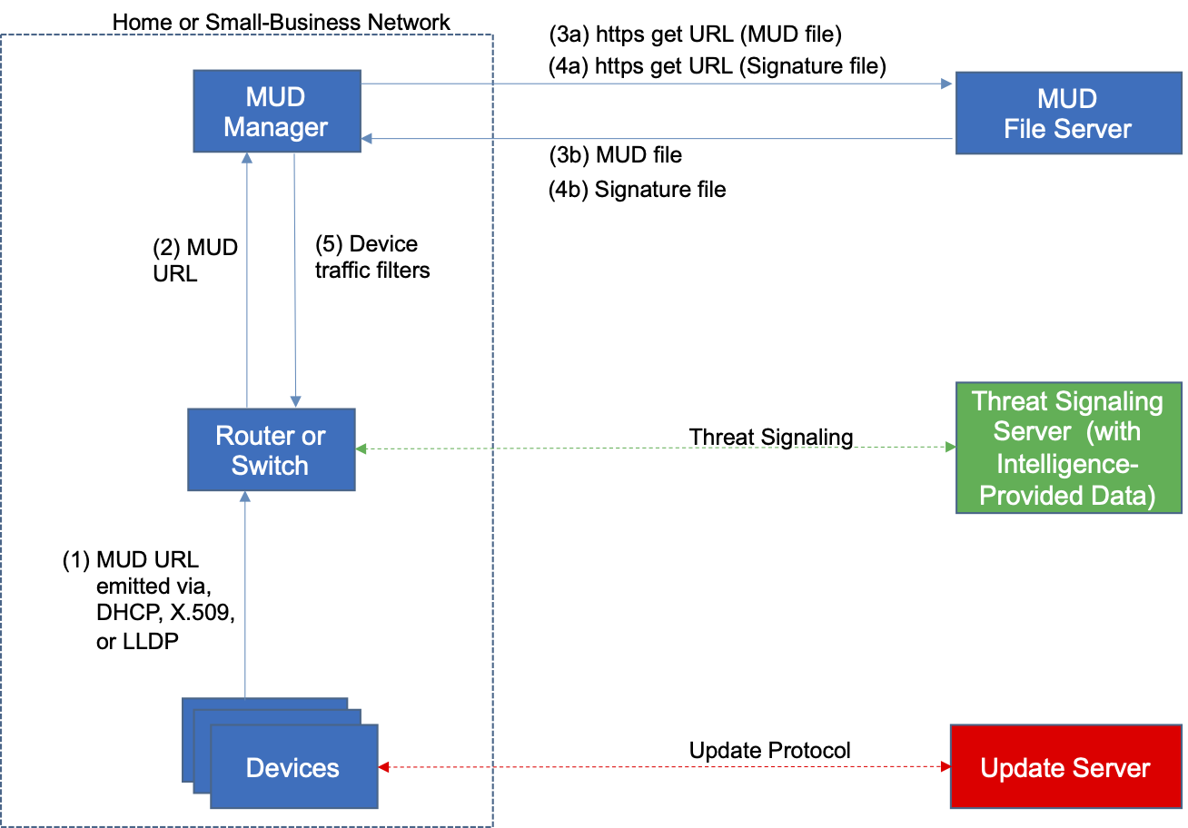
Figure 1‑1 depicts a general reference design for all four builds. It consists of three main components: support for MUD, support for threat signaling, and support for periodic updates.
Figure 1‑1 Reference Architecture
1.2.2.1 Support for MUD
A new functional component, the MUD manager, is introduced to augment the existing networking functionality offered by the home/small-business network router or switch. Note that the MUD manager is a logical component. Physically, the functionality it provides can and often will be combined with that of the network router or switch in a single device.
IoT devices must somehow be associated with a MUD file. The MUD specification describes three possible mechanisms through which the IoT device can provide the MUD file URL to the network: inserting the MUD URL into the Dynamic Host Configuration Protocol (DHCP) address requests that they generate when they attach to the network (e.g., when powered on), providing the MUD URL in a Link Layer Discovery Protocol (LLDP) frame, or providing the MUD URL as a field in an X.509 certificate that the device provides to the network via a protocol such as Tunnel Extensible Authentication Protocol. In addition, the MUD specification provides flexibility to enable other mechanisms by which MUD file URLs can be associated with IoT devices. One such alternative mechanism is to associate the device with its MUD file by using the device’s bootstrapping information that is conveyed as part of the Wi-Fi Easy Connect (also referred to as Device Provisioning Protocol—DPP) onboarding process. This is the mechanism implemented in Build 3.
Figure 1‑1 uses labeled arrows to depict the steps involved in supporting MUD:
The IoT device emits a MUD URL by using a mechanism such as DHCP, LLDP, or X.509 certificate (step 1).
The router extracts the MUD URL from the protocol frame of whatever mechanism was used to convey it and forwards this MUD URL to the MUD manager (step 2).
Once the MUD URL is received, the MUD manager uses https to request the MUD file from the MUD file server by using the MUD URL provided in the previous step (step 3a); if successful, the MUD file server at the specified location will serve the MUD file (step 3b).
Next, the MUD manager uses https to request the signature file associated with the MUD file (step 4a) and upon receipt (step 4b) verifies the MUD file by using its signature file.
The MUD file describes the communications requirements for the IoT device. Once the MUD manager has determined the MUD file to be valid, the MUD manager converts the access control rules in the MUD file into access control entries (e.g., access control lists—ACLs, firewall rules, or flow rules) and installs them on the router or switch (step 5).
Once the device’s access control rules are applied to the router or switch, the MUD-capable IoT device will be able to communicate with approved local hosts and internet hosts as defined in the MUD file, and any unapproved communication attempts will be blocked.
1.2.2.2 Support for Updates
To provide additional security, the reference architecture also supports periodic updates. All builds include a server that is meant to represent an update server to which MUD will permit devices to connect. Each IoT device on an operational network should be configured to periodically contact its update server to download and apply security patches, ensuring that it is running the most up-to-date and secure code available. To ensure that such updates are possible, the IoT device’s MUD file must explicitly permit the IoT device to receive traffic from the update server. Although regular manufacturer updates are crucial to IoT security, the builds described in this practice guide demonstrate only the ability to receive faux updates from a notional update server.
1.2.2.3 Support for Threat Signaling
To provide additional protection for both MUD-capable and non-MUD-capable devices, the reference architecture also incorporates support for threat signaling. The router or switch can receive threat feeds from a threat signaling server to use as a basis for restricting certain types of network traffic. For example, both MUD-capable and non-MUD-capable devices can be prevented from connecting to internet domains that have been identified as potentially malicious.
1.2.2.4 Build-Specific Features
The reference architecture depicted in Figure 1‑1 is intentionally general. Each build instantiates this reference architecture in a unique way, depending on the equipment used and the capabilities supported. The logical and physical architectures of each build are depicted and described in NIST SP 1800-15B: Approach, Architecture, and Security Characteristics. While all four builds support MUD and the ability to receive faux updates from a notional update server, only Build 2 currently supports threat signaling. Only Build 3 currently supports onboarding MUD-capable devices using the Wi-Fi Alliance Wi-Fi Easy Connect protocol. Build 1 and Build 2 include nonstandard device discovery technology to discover, inventory, profile, and classify attached devices. Such classification can be used to validate that the access being granted to each device is consistent with that device’s manufacturer and model. In Build 2, a device’s manufacturer and model can be used as a basis for identifying and enforcing that device’s traffic profile.
Briefly, the four builds of the reference architecture that have been completed and demonstrated are as follows:
Build 1 uses products from Cisco Systems, DigiCert, Forescout, and Molex. The Cisco MUD manager supports MUD, and the Forescout virtual appliances and enterprise manager perform non-MUD-related device discovery on the network. Molex PoE Gateway and Light Engine is used as a MUD-capable IoT device. Certificates from DigiCert are also used.
Build 2 uses products from MasterPeace Solutions Ltd., Global Cyber Alliance (GCA), ThreatSTOP, and DigiCert. The MasterPeace Solutions Yikes! router, cloud service, and mobile application support MUD as well as perform device discovery on the network and apply additional traffic rules to both MUD-capable and non-MUD-capable devices based on device manufacturer and model. The GCA threat agent, Quad9 DNS service, and ThreatSTOP threat MUD file server support threat signaling. Certificates from DigiCert are also used.
Build 3 uses products from CableLabs and DigiCert. CableLabs Micronets (e.g., Micronets Gateway, Micronets Manager, Micronets mobile phone application, and related service provider cloud-based infrastructure) supports MUD and implements the Wi-Fi Alliance’s Wi-Fi Easy Connect protocol to securely onboard devices to the network. It also uses software-defined networking to create separate trust zones (e.g., network segments) called micronets to which devices are assigned according to their intended network function. Certificates from DigiCert are also used.
Build 4 uses software developed at the NIST Advanced Networking Technologies Laboratory. This software supports MUD and is intended to serve as a working prototype of the MUD request for comments (RFC) to demonstrate feasibility and scalability. Certificates from DigiCert are also used.
The logical architectures and detailed descriptions of Builds 1, 2, 3, and 4 can be found in NIST SP 1800-15B: Approach, Architecture, and Security Characteristics.
1.2.3 Physical Architecture Overview
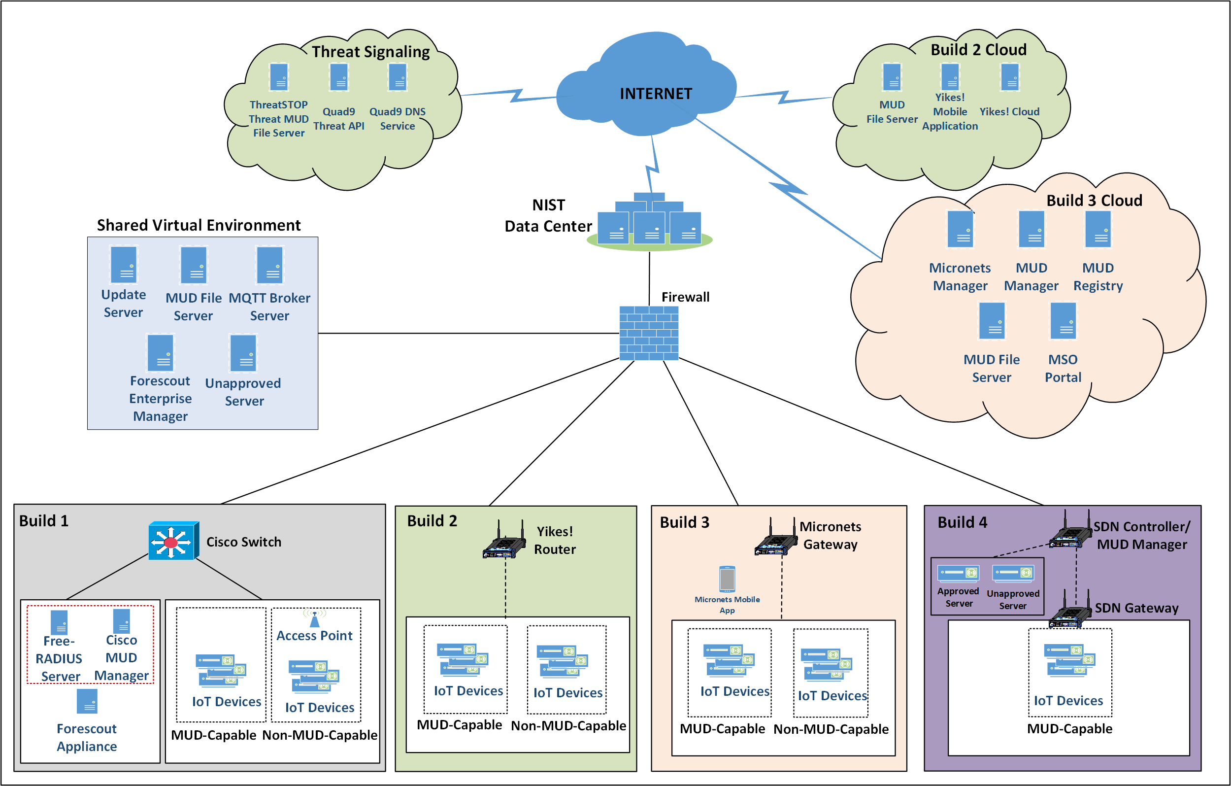
Figure 1‑2 depicts the high-level physical architecture of the NCCoE laboratory environment. This implementation currently supports four builds and has the flexibility to implement additional builds in the future. As depicted, the NCCoE laboratory network is connected to the internet via the NIST data center. Access to and from the NCCoE network is protected by a firewall. The NCCoE network includes a shared virtual environment that houses an update server, a MUD file server, an unapproved server (i.e., a server that is not listed as a permissible communications source or destination in any MUD file), a Message Queuing Telemetry Transport (MQTT) broker server, and a Forescout enterprise manager. These components are hosted at the NCCoE and are used across builds where applicable. The Transport Layer Security (TLS) certificate and Premium Certificate used by the MUD file server are provided by DigiCert.
The following four builds, as depicted in the diagram, are supported within the physical architecture:
Build 1 network components consist of a Cisco Catalyst 3850-S switch, a Cisco MUD manager, a FreeRADIUS server, and a virtualized Forescout appliance on the local network. Build 1 also requires support from all components that are in the shared virtual environment, including the Forescout enterprise manager.
Build 2 network components consist of a MasterPeace Solutions Ltd. Yikes! router on the local network. Build 2 requires support from the MUD file server, Yikes! cloud, and a Yikes! mobile application that are resident on the Build 2 cloud. The Yikes! router includes threat-signaling capabilities (not depicted) that have been integrated with it. Build 2 also requires support from threat-signaling cloud services that consist of the ThreatSTOP threat MUD file server, Quad9 threat application programming interface (API), and Quad9 DNS service. Build 2 uses only the update server and unapproved server components that are in the shared virtual environment.
Build 3 network components consist of a CableLabs Micronets Gateway/wireless access point (AP). The Gateway/wireless AP resides on the local network and operates in conjunction with various service provider components and partner/service provider offerings that reside in the Micronets virtual environment in the Build 3 cloud. The Micronets Gateway is controlled by a Micronets Manager that resides in the Build 3 cloud and that coordinates a number of cloud-based Micronets micro-services, some of which are depicted. Build 3 also includes a Micronets mobile application that provides the user and device interfaces for device onboarding.
Build 4 network components consist of a software-defined networking (SDN)-capable gateway/switch on the local network and an SDN controller/MUD manager and approved and unapproved servers that are located remotely from the local network. Build 4 also uses the MUD file server that is resident in the shared virtual environment.
IoT devices used in all four builds include both MUD-capable and non-MUD-capable IoT devices. The MUD-capable IoT devices used, which vary across builds, include Raspberry Pi, ARTIK, u-blox, Intel UP Squared, BeagleBone Black, NXP i.MX 8M (devkit), and the Molex Light Engine controlled by PoE Gateway. Non-MUD-capable devices used, which also vary across builds, include a wireless access point, cameras, a printer, mobile phones, lighting devices, a connected assistant device, a baby monitor, and a digital video recorder. Each of the completed builds and the roles that their components play in their architectures are explained in more detail in NIST SP 1800-15B.
The remainder of this guide describes how to implement Builds 1, 2, 3, and 4.
Figure 1‑2 NCCoE Physical Architecture
1.3 Typographic Conventions
The following table presents typographic conventions used in this volume.
Typeface/Symbol |
Meaning |
Example |
|---|---|---|
Italics |
file names and path names; references to documents that are not hyperlinks; new terms; and placeholders |
For language use and style guidance, see the NCCoE Style Guide. |
Bold |
names of menus, options, command buttons, and fields |
Choose File > Edit. |
Monospace |
command-line input, onscreen computer output, sample code examples, and status codes |
|
Monospace (block) |
multi-line input, on-screen computer output, sample code examples, status codes |
% mkdir -v nccoe_projects
mkdir: created directory 'nccoe_projects'
|
blue text |
link to other parts of the document, a web URL, or an email address |
All publications from NIST’s NCCoE are available at https://www.nccoe.nist.gov. |
2 Build 1 Product Installation Guides
This section of the practice guide contains detailed instructions for installing and configuring all the products used to implement Build 1. For additional details on Build 1’s logical and physical architectures, please refer to NIST SP 1800-15B.
2.1 Cisco MUD Manager
This section describes how to deploy Cisco’s MUD manager version 1.0, which uses a MUD-based authorization system in the network, using Cisco Catalyst switches, FreeRADIUS, and Cisco MUD manager.
2.1.1 Cisco MUD Manager Overview
The Cisco MUD manager is an open-source implementation that works with IoT devices that emit their MUD URLs. In this implementation we tested two MUD URL emission methods: DHCP and LLDP. The MUD manager is supported by a FreeRADIUS server that receives MUD URLs from the switch. The MUD URLs are extracted by the DHCP server and are sent to the MUD manager via Remote Authentication Dial-In User Service (RADIUS) messages. The MUD manager is responsible for retrieving the MUD file and corresponding signature file associated with the MUD URL. The MUD manager verifies the legitimacy of the file and then translates the contents to an Internet Protocol (IP) ACL-based policy that is installed on the switch.
The version of the Cisco MUD manager used in this project is a proof-of-concept implementation that is intended to introduce advanced users and engineers to the MUD concept. It is not a fully automated MUD manager implementation, and some protocol features are not present. At implementation, the “model” construct was not yet implemented. In addition, if a DNS-based system changes its address, this will not be noticed. Also, IPv6 access has not been fully supported.
2.1.2 Cisco MUD Manager Configurations
The following subsections document the software, hardware, and network configurations for the Cisco MUD manager.
2.1.2.1 Hardware Configuration
Cisco requires installing the MUD manager and FreeRADIUS on a single server with at least 2 gigabytes of random access memory. This server must integrate with at least one switch or router on the network. For this build we used a Catalyst 3850-S switch.
2.1.2.2 Network Configuration
The MUD manager and FreeRADIUS server instances were installed and configured on a dedicated machine leveraged for hosting virtual machines in the Build 1 lab environment. This machine was then connected to virtual local area network (VLAN) 2 on the Catalyst 3850-S and assigned a static IP address.
2.1.2.3 Software Configuration
For this build, the Cisco MUD manager was installed on an Ubuntu 18.04.01 64-bit server. However, there are many approaches for implementation. Alternatively, the MUD manager can be built via docker containers provided by Cisco.
The Cisco MUD manager can operate on Linux operating systems, such as
Ubuntu 18.04.01
Amazon Linux
The Cisco MUD manager requires the following installations and components:
OpenSSL
cJSON
MongoDB
Mongo C driver
Libcurl
FreeRADIUS server
At a high level, the following software configurations and integrations are required:
The Cisco MUD manager requires integration with a switch (such as a Catalyst 3850-S) that connects to an authentication, authorization, and accounting (AAA) server that communicates by using the RADIUS protocol (i.e., a RADIUS server).
The RADIUS server must be configured to identify a MUD URL received in an accounting request message from a device it has authenticated.
The MUD manager must be configured to process a MUD URL received from a RADIUS server and return access control policy to the RADIUS server, which is then forwarded to the switch.
2.1.3 Setup
2.1.3.1 Preinstallation
Cisco’s DevNet GitHub page provides documentation that we followed to complete this section: https://github.com/CiscoDevNet/MUD-Manager/tree/3.0.1#dependancies
Open a terminal window, and enter the following command to log in as root:
sudo su
Change to the root directory:
cd /
To install OpenSSL from the terminal, enter the following command:
apt-get install openssl
If unable to link to OpenSSL, install it by entering this command:
apt-get install libcurl4-openssl-dev
To install cJSON, download it from GitHub by entering the following command:
git clone https://github.com/DaveGamble/cJSON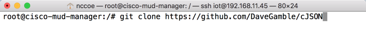
Change directories to the cJSON folder by entering the following command:
cd cJSON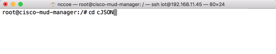
Build cJSON by entering the following commands:
make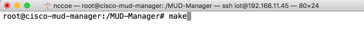
make install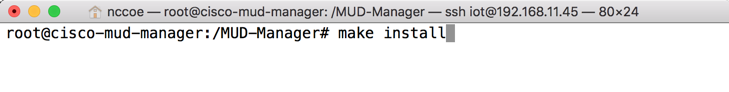
Change directories back a folder by entering the following command:
cd ..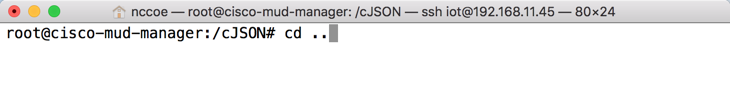
To install MongoDB, enter the following commands:
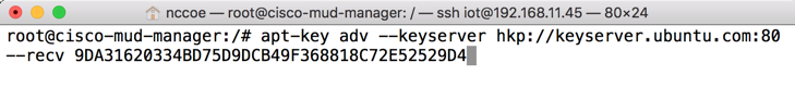
Import the public key:
apt-key adv --keyserver hkp://keyserver.ubuntu.com:80 --recv 9DA31620334BD75D9DCB49F368818C72E52529D4
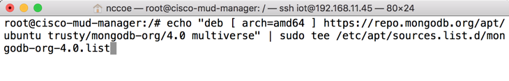
Create a list file for MongoDB:
echo "deb [ arch=amd64 ] https://repo.mongodb.org/apt/ubuntu trusty/mongodb-org/4.0 multiverse" \| sudo tee /etc/apt/sources.list.d/mongodb-org-4.0.list
Reload the local package database:
apt-get update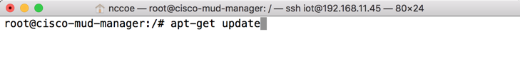
Install the MongoDB packages:
apt-get install -y mongodb
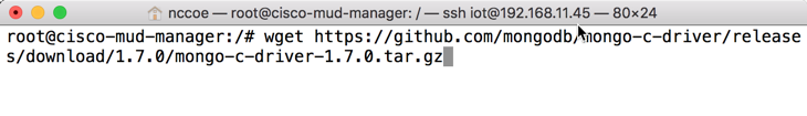
To install the Mongo C driver, enter the following command:
wget https://github.com/mongodb/mongo-c-driver/releases/download/1.7.0/mongo-c-driver-1.7.0.tar.gz
Untar the file by entering the following command:
tar -xzf mongo-c-driver-1.7.0.tar.gz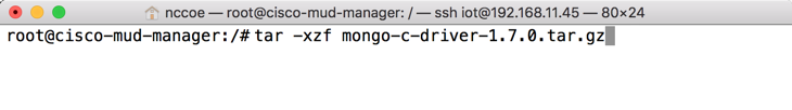
Change into the mongo-c-driver-1.7.0 directory by entering the following command:
cd mongo-c-driver-1.7.0/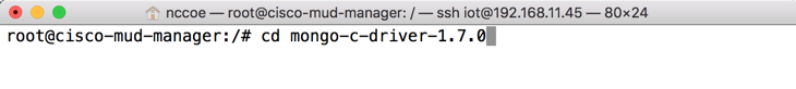
Build the Mongo C driver by entering the following commands:
./configure --disable-automatic-init-and-cleanup --with-libbson=bundled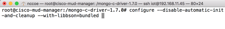
makemake install
Change directories back a folder by entering the following command:
cd ..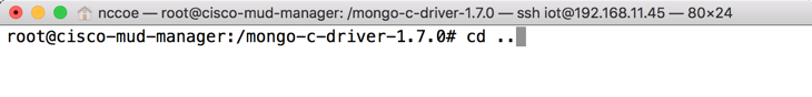
To install libcurl, enter the following command:
sudo apt-get install libcurl4-openssl-dev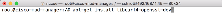
2.1.3.2 MUD Manager Installation
A portion of the steps in this section are documented on Cisco’s DevNet GitHub page: https://github.com/CiscoDevNet/MUD-Manager/tree/3.0.1#building-the-mud-manager
Open a terminal window, and enter the following command to log in as root:
sudo suChange to the root directory by entering the following command:
cd /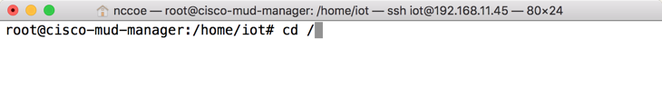
To install the MUD manager, download it from Cisco’s GitHub by entering the following command:
git clone https://github.com/CiscoDevNet/MUD-Manager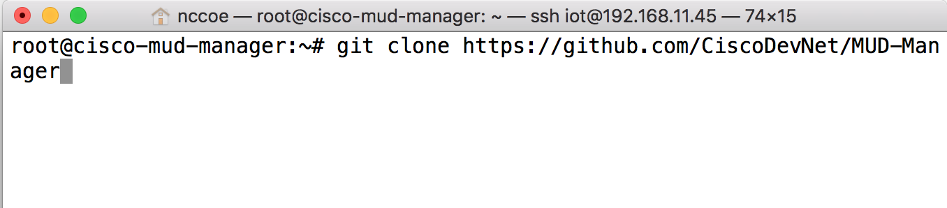
Change into the MUD manager directory:
cd MUD-Manager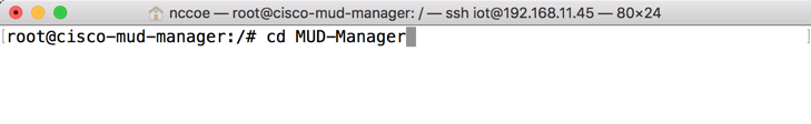
Build the MUD manager by entering the following commands:
./configure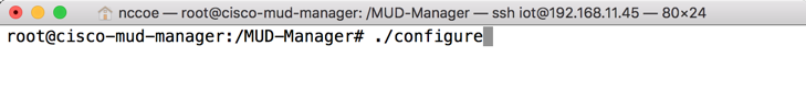
Note: If a “pkg-config error” is thrown, run the command below to install the missing package:
apt-get install pkg-config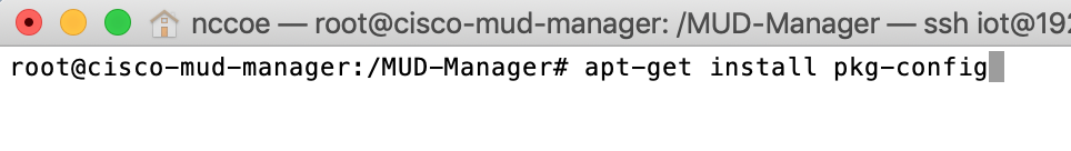
makeNote: If an “ac.local error” is thrown, run the command below to install the missing package:
apt-get install automake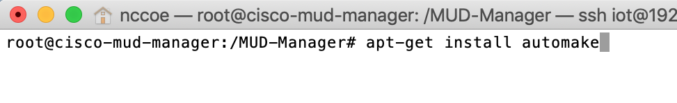
make install
2.1.3.3 MUD Manager Configuration
This section describes configuring the MUD manager to communicate with the NCCoE MUD file server and defining the attributes used for translating the fetched MUD files. Details about the configuration file and additional fields that can be set within this file can be accessed here: https://github.com/CiscoDevNet/MUD-Manager#editing-the-configuration-file.
In the terminal, change to the MUD manager directory:
cd /MUD-Manager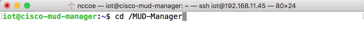
Copy the contents of the sample mud_manager_conf.json file to a different file:
sudo cp examples/mud_manager_conf.json mud_manager_conf_nccoe.json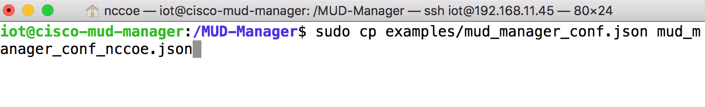
Modify the contents of the new MUD manager configuration file:
sudo vim mud_manager_conf_nccoe.json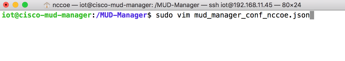
{

   "MUD_Manager_Version" : 3,

   "MUDManagerAPIProtocol" : "http",

   "ACL_Prefix" : "ACS:",

   "ACL_Type" : "dACL-ingress-only",

   "COA_Password" : "cisco",

   "VLANs" : [

      { "VLAN_ID" : 3,

        "v4addrmask" : "192.168.13.0 0.0.0.255"

      },

      { "VLAN_ID" : 4,

        "v4addrmask" : "192.168.14.0 0.0.0.255"

      },

      { "VLAN_ID" : 5,

        "v4addrmask" : "192.168.15.0 0.0.0.255"

      }

   ],

   "Manufacturers" : [

      { "authority" : "mudfileserver",

        "cert" : "/home/mudtester/digicertca-chain.crt",

        "web_cert": "/home/mudtester/digicertchain.pem",

        "my_controller_v4" : "192.168.10.125",

        "my_controller_v6" : "2610:20:60CE:630:B000::7",

        "local_networks_v4" : "192.168.10.0 0.0.0.255",

        "local_networks_v6" : "2610:20:60CE:630:B000::",

        "vlan_nw_v4" : "192.168.13.0 0.0.0.255",

        "vlan" : 3

      },

      {

      "authority" : "www.gmail.com",

        "cert" : "/home/mudtester/digicertca-chain.crt",

        "web_cert": "/home/mudtester/digicertchain.pem",

        "vlan_nw_v4" : "192.168.14.0 0.0.0.255",

        "vlan" : 4

      }

   ],

   "DNSMapping" : {

      "www.osmud.org" : "198.71.233.87",

      "www.mqttbroker.com" : "192.168.4.6",

      "us.dlink.com" : "54.187.217.118",

      "www.nossl.net": "40.68.201.127",

      "www.trytechy.com" : "99.84.104.21"

    },

    "DNSMapping_v6" : {

      "www.mqttbroker.com" : "2610:20:60CE:630:B000::6",

      "www.updateserver.com" : "2610:20:60CE:630:B000::7",

      "www.dominiontea.com": "2a03:2880:f10c:83:face:b00c:0:25de"

    },

    "ControllerMapping" : {

      "https://www.google.com" : "192.168.10.104",

      "http://lightcontroller.example2.com": "192.168.4.77",

      "http://lightcontroller.example.com": "192.168.4.78"

    },

    "ControllerMapping_v6" : {

      "https:/www.google.com" : "ffff:2343:4444:::",

      "http://lightcontroller.example2.com": "ffff:2343:4444:::",

      "http://lightcontroller.example.com": "ffff:2343:4444:::"

     },

     "DefaultACL" : ["permit tcp any eq 22 any","permit udp any eq 68 any eq 67","permit udp any any eq 53", "deny ip any any"],

     "DefaultACL_v6" : ["permit udp any any eq 53", "deny ipv6 any any"]

  }
Details about the contents of the configuration file can be found at the link provided at the start of this section.
2.1.3.4 FreeRADIUS Installation
Install the dependencies for FreeRADIUS:
sudo apt-get install -y libtalloc-dev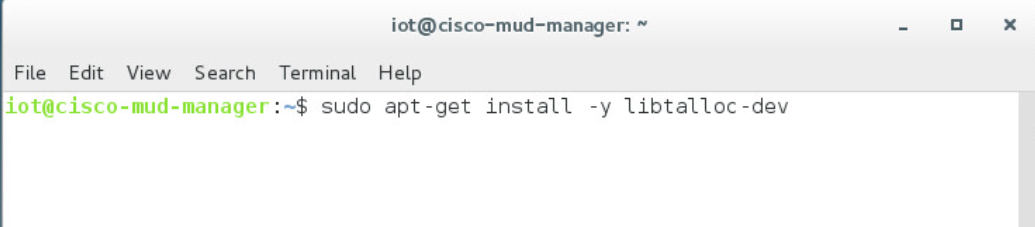
sudo apt-get install -y libjson-c-dev
sudo apt-get install -y libcurl4-gnutls-dev
sudo apt-get install -y libperl-dev
sudo apt-get install -y libkqueue-dev
sudo apt-get install -y libssl-dev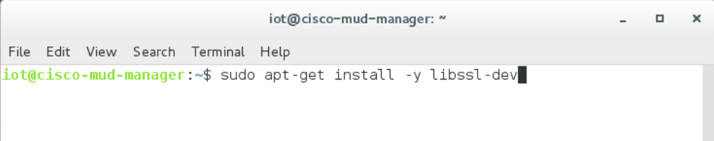
Download the source by entering the following command. (Note: Version 3.0.19 and later are recommended.)
wget ftp://ftp.freeradius.org/pub/freeradius/freeradius-server-3.0.19.tar.gz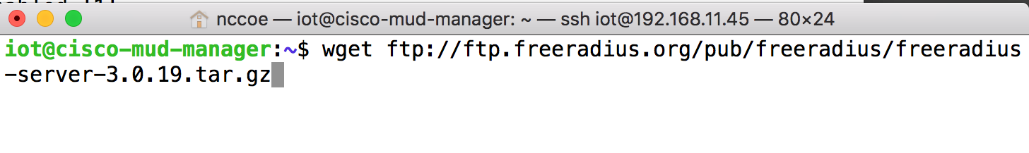
Untar the downloaded file by entering the following command:
tar -xf freeradius-server-3.0.19.tar.gz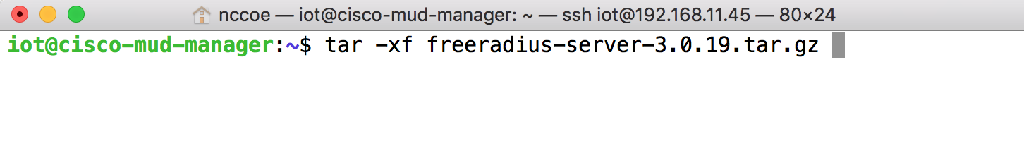
Move the FreeRADIUS directory to the root directory:
sudo mv freeradius-server-3.0.19/ /
Change to the FreeRADIUS directory:
cd /freeradius-server-3.0.19/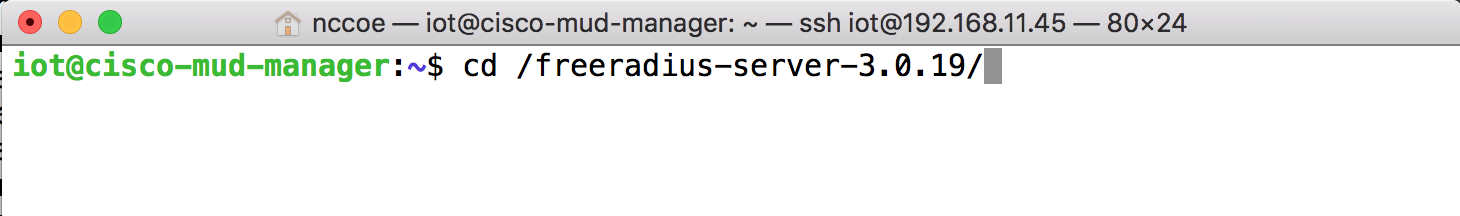
Make and install the source by entering the following:
sudo ./configure --with-rest --with-json-c --with-perl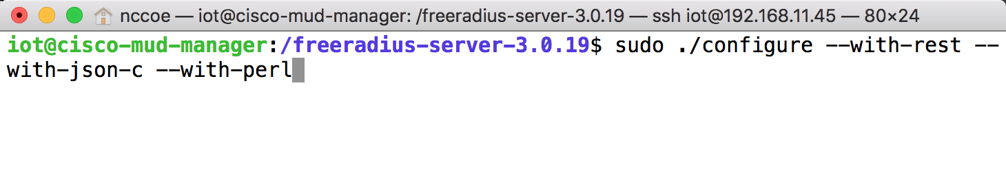
sudo make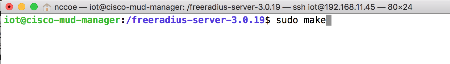
sudo make install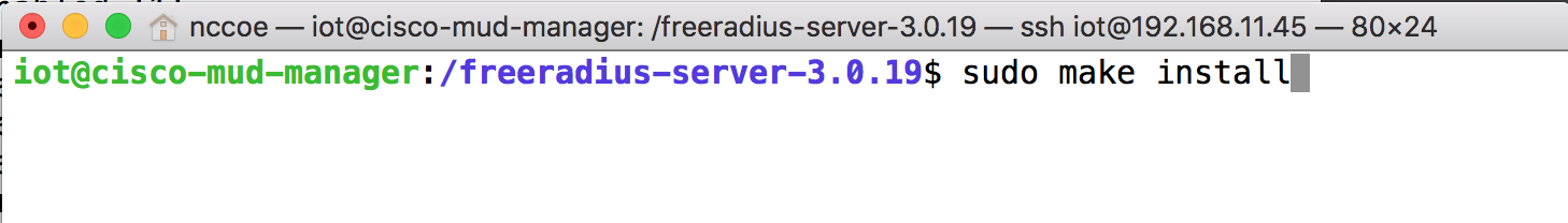
2.1.3.5 FreeRADIUS Configuration
Change to the FreeRADIUS subdirectory in the MUD manager directory:
cd /MUD-Manager/examples/AAA-LLDP-DHCP/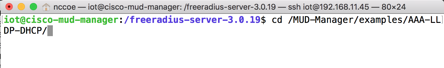
Run the setup script:
sudo ./FR-setup.sh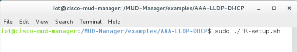
Enter the following command to log in as root:
sudo su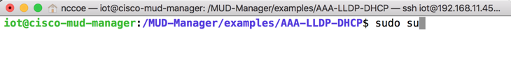
Change to the RADIUS directory:
cd /usr/local/etc/raddb/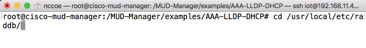
Open the clients.conf file:
vim clients.conf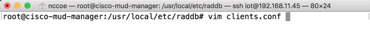
Add the network access server (NAS) as an authorized client in the configuration file on the server by adding an entry for the NAS in the client.conf file that is opened. (Note: replace the IP address below with the IP address of the NAS, and insert the “secret” configured on the NAS to talk to the RADIUS servers.)
client 192.168.10.2 {
   ipaddr = 192.168.10.2
   secret = cisco
}
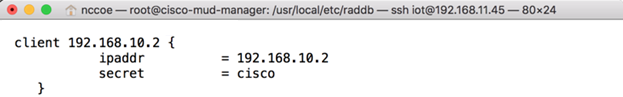
Save and close the file.
2.1.3.6 Start MUD Manager and FreeRADIUS Server
Start and enable the database by executing the following commands:
sudo systemctl start mongod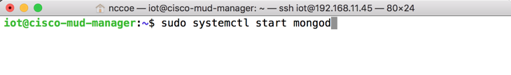
sudo systemctl enable mongod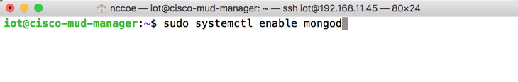
Start the MUD manager in the foreground with logging enabled by entering the following command:
sudo mud_manager -f /MUD-Manager/mud_manager_conf_nccoe.json -l 3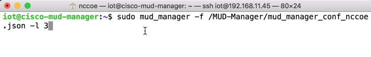
The following output should appear if the service started successfully:
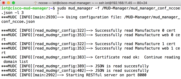
Start the FreeRADIUS service in the foreground with logging enabled by entering the following command:
sudo radiusd -Xxx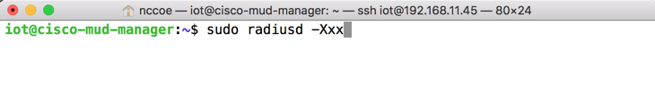
At this point all the processes required to support MUD are running on the server side, and the next step is to configure the Cisco Catalyst switch. Once the switch configuration detailed in the Cisco Switch–Catalyst 3850-S setup section is completed, any DHCP activity on the network should appear in the output of the FreeRADIUS and MUD manager logs.
2.2 MUD File Server
2.2.1 MUD File Server Overview
For this build, the NCCoE built a MUD file server hosted within the lab infrastructure. This file server signs and stores the MUD files along with their corresponding signature files for the MUD-capable IoT devices used in the build. The MUD file server is also responsible for serving the MUD file and the corresponding signature file upon request from the MUD manager.
2.2.2 Configuration Overview
The following subsections document the software and network configurations for the MUD file server.
2.2.2.1 Network Configuration
This server was hosted in the NCCoE’s virtual environment, functioning as a cloud service. Its IP address was statically assigned.
2.2.2.2 Software Configuration
For this build, the server ran on the CentOS 7 operating system. The MUD files and signatures were hosted by an Apache web server and configured to use Secure Sockets Layer/Transport Layer Security (SSL/TLS) encryption.
2.2.2.3 Hardware Configuration
The MUD file server was hosted in the NCCoE’s virtual environment, functioning as a cloud service.
2.2.3 Setup
The following subsections describe the process for configuring the MUD file server.
2.2.3.1 Apache Web Server
The Apache web server was set up by using the official Apache documentation at https://httpd.apache.org/docs/current/install.html. After that, SSL/TLS encryption was set up by using the digital certificate and key obtained from DigiCert. This was set up by using the official Apache documentation, found at https://httpd.apache.org/docs/current/ssl/ssl_howto.html.
2.2.3.2 MUD File Creation and Signing
This section details creating and signing a MUD file on the MUD file server. The MUD specification does not mandate that this signing process be performed on the MUD file server itself.
2.2.3.2.1 MUD File Creation
An online tool called MUD Maker was used to build MUD files. Once the permitted communications have been defined for the IoT device, proceed to www.mudmaker.org to leverage the online tool. There is also a list of sample MUD files on the site, which can be used as a reference. Upon navigating to www.mudmaker.org, complete the following steps to create a MUD file:
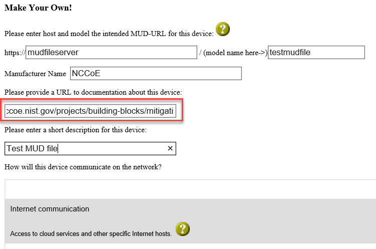
Specify the host that will be serving the MUD file and the model name of the device in the appropriate input fields, which are outlined in red in the screenshot below. (Note: this will result in the MUD URL for this device.)
Sample input: mudfileserver, testmudfile
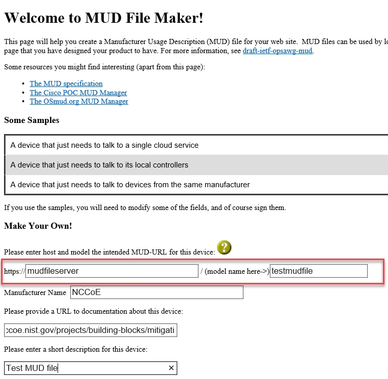
Specify the Manufacturer Name of the device in the appropriate input field, which is outlined in red in the screenshot below:
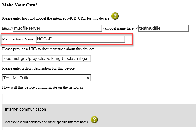
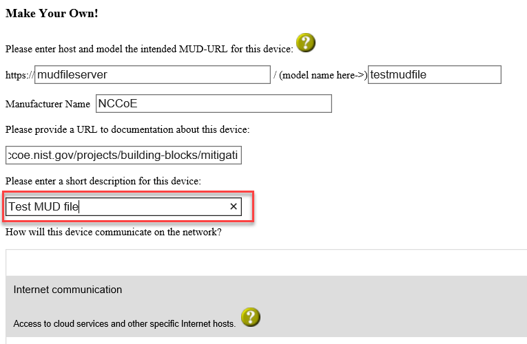
Include a URL to provide documentation about this device in the appropriate input field, which is outlined in red in the screenshot below:
Include a short description of the device in the appropriate input field, which is outlined in red in the screenshot below:
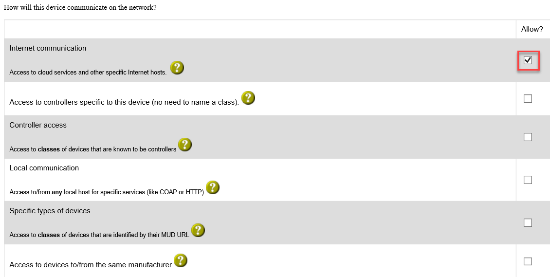
Check the boxes for the types of network communication that are allowed for the device:
Specify the IP version that the device leverages:
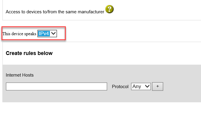
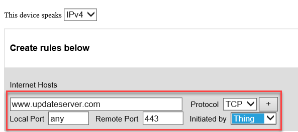
Specify values for the fields (Internet Hosts, Protocol, Local Port, Remote Port, and Initiated by) that describe the communications that will be permitted for the device:
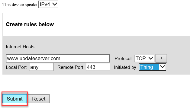
Click Submit to generate the MUD file:
Once completed, the page will redirect to the following page that outputs the MUD file on the screen. Click Download to download the MUD file, which is a .JSON file:
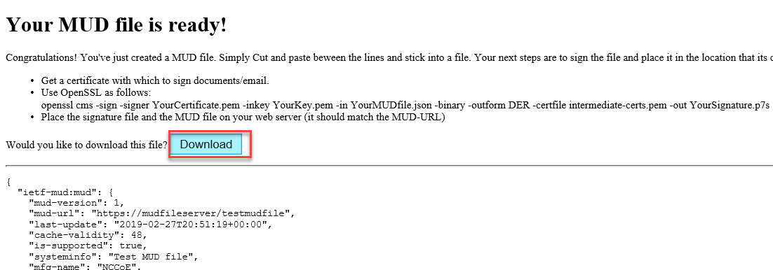
Click Save to store a copy of the MUD file:

2.2.3.2.2 MUD File Signature Creation and Verification
In this build, OpenSSL is used to sign and verify MUD files. This example uses the MUD file created in the previous section, which is named ublox.json; the Signing Certificate; the Private Key for the Signing Certificate; the Intermediate Certificate for the Signing Certificate; and the Certificate of the Trusted Root Certificate Authority (CA) for the Signing Certificate.
Sign the MUD file by using the following command:
sudo openssl cms -sign -signer <Signing Certificate> -inkey <Private Key for Signing Certificate> -in <Name of MUD File> -binary -outform DER -binary-certfile <Intermediate Certificate for Signing Certificate> -out <Name of MUD File without the .json file extension>.p7s
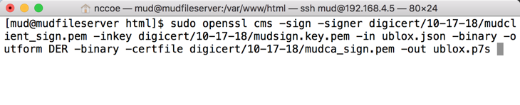
This will create a signature file for the MUD file that has the same name as the MUD file but ends with the .p7s file extension, i.e., in our case ublox.p7s.
Manually verify the MUD file signature by using the following command:
sudo openssl cms -verify -in <Name of MUD File>.p7s -inform DER -content <Name of MUD File>.json -CAfile <Certificate of Trusted Root Certificate Authority for Signing Certificate>
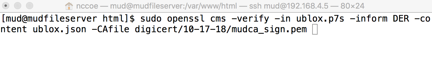
If a valid file signature was created successfully, a corresponding message should appear. Both the MUD file and MUD file signature should be placed on the MUD file server in the Apache server directory.
2.3 Cisco Switch–Catalyst 3850-S
2.3.1 Cisco 3850-S Catalyst Switch Overview
The switch used in this build is an enterprise-class, layer 3 switch. It is a Cisco Catalyst 3850-S that had been modified to support MUD functionality as a proof-of-concept implementation. In addition to providing DHCP services, the switch acts as a broker for connected IoT devices for authentication, authorization, and accounting through a FreeRADIUS server. The Link Layer Discovery Protocol (LLDP) is enabled on ports that MUD-capable devices are plugged into to help facilitate recognition of connected IoT device features, capabilities, and neighbor relationships at layer 2. Additionally, an access session policy is configured on the switch to enable port control for multihost authentication and port monitoring. The combined effect of these switch configurations is a dynamic access list, which has been generated by the MUD manager, being active on the switch to permit or deny access to and from MUD-capable IoT devices.
2.3.2 Configuration Overview
The following subsections document the network, software, and hardware configurations for the Cisco Catalyst 3850-S switch.
2.3.2.1 Network Configuration
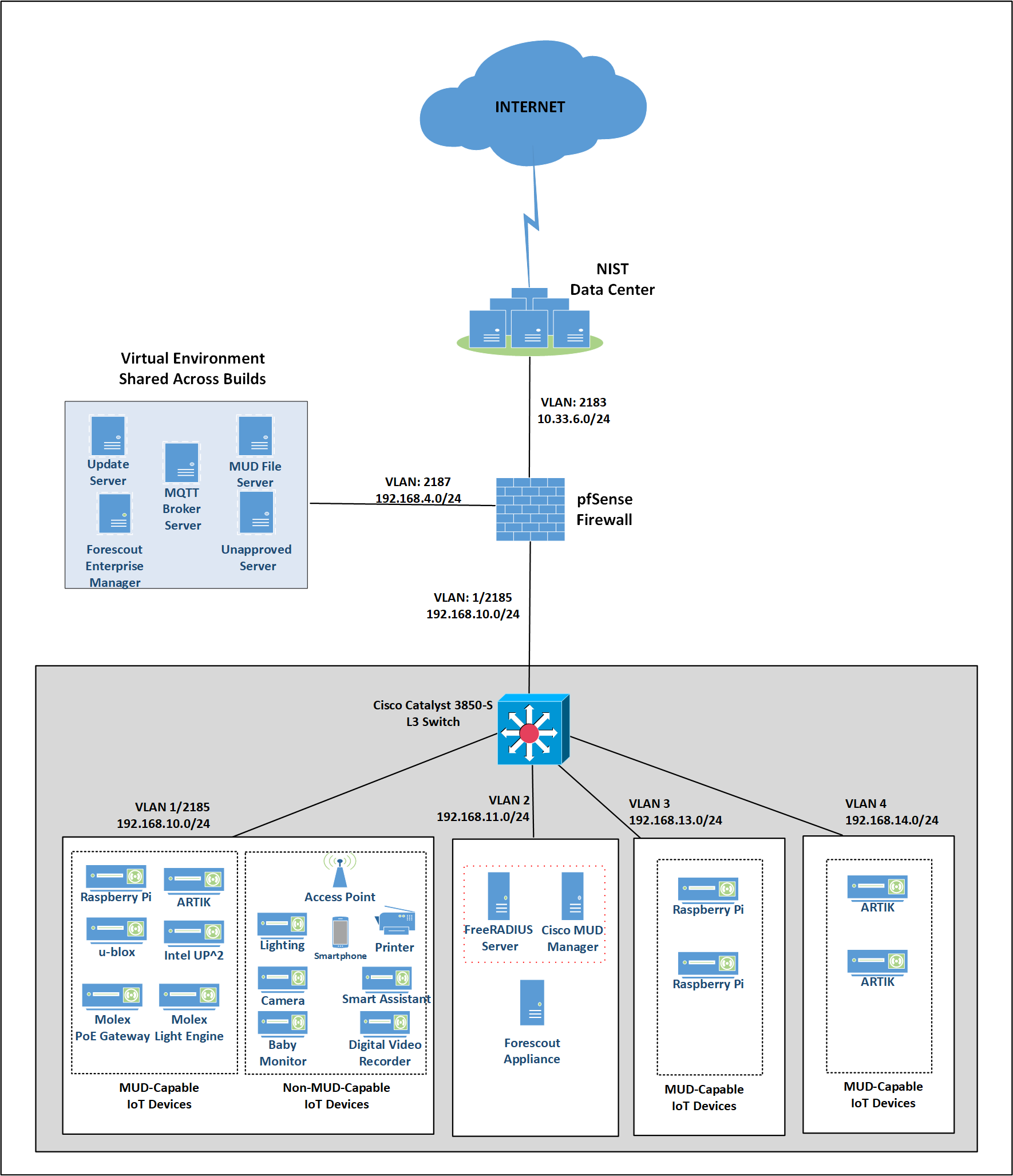
This section describes how to configure the required Cisco Catalyst 3850-S switch to support the build. A special image for the Catalyst 3850-S was provided by Cisco to support MUD-specific functionality. In our build, the switch is integrated with a DHCP server and a FreeRADIUS server, which together support delivery of the MUD URL to the MUD manager via either DHCP or LLDP. The MUD manager is also able to generate and send a dynamic access list to the switch, via the RADIUS server, to permit or deny access to and from the IoT devices. In addition to hosting directly connected IoT devices on VLANs 1, 3, and 4, the switch hosts both the MUD manager and the FreeRADIUS servers on VLAN 2. As illustrated in Figure 2‑1, each locally configured VLAN is protected by a firewall that connects the lab environment to the NIST data center, which provides internet access for all connected devices.
Figure 2‑1 Physical Architecture–Build 1
2.3.2.2 Software Configuration
The prototype, MUD-capable Cisco 3850-S used in this build is running internetwork operating system (IOS) version 16.09.02.
2.3.2.3 Hardware Configuration
The Catalyst 3850-S switch configured in the lab consists of 24 one-gigabit Ethernet ports with two optional 10-gigabit Ethernet uplink ports. A customized version of Cat-OS is installed on the switch. The versions of the OS are as follows:
Cat3k_caa-guestshell.16
Cat3k_caa-rpbase.16.06
Cat3k_caa-rpcore.16.06
Cat3k_caa-srdriver.16.06.0
Cat3k_caa-webui.16.06.0
2.3.3 Setup
Table 2‑1 lists the Cisco 3850-S switch running configuration used for the lab environment. In addition to the IOS version and a few generic configuration items, configuration items specifically relating to integration with the MUD manager and IoT devices are highlighted in bold fonts; these include DHCP, LLDP, AAA, RADIUS, and policies regarding access session. Table 2‑1 also provides a description of each configuration item for ease of understanding.
Table 2‑1 Cisco 3850-S Switch Running Configuration
Configuration Item |
Description |
|---|---|
version 16.9 no service pad service timestamps debug datetime msec service timestamps log datetime msec service call-home no platform punt-keepalive disable-kernel-core ! hostname Build1 ! |
general overview of configuration information needed to configure AAA to use RADIUS and configure the RADIUS server itself. Note that the FreeRADIUS and AAA passwords must match. |
aaa new-model ! |
enables AAA |
aaa authentication dot1x default group radius |
creates an 802.1X AAA authentication method list |
aaa authorization network default group radius |
configures network authorization via RADIUS, including network-related services such as VLAN assignment |
aaa accounting identity default start-stop group radius |
enables accounting method list for session-aware networking subscriber services |
aaa accounting network default start-stop group radius ! |
enables accounting for all network-related service requests |
aaa server radius dynamic-author
!
aaa session-id common
|
enables dynamic authorization local server configuration mode and specifies a RADIUS client/key from which a device accepts change of authorization (CoA) and disconnect requests |
radius server AAA address ipv4 192.168.11.45 auth-port 1812 |
enables AAA server from the list of multiple AAA servers configured |
acct-port 1813
|
uses the IP address and ports on which the FreeRADIUS server is listening |
ip routing ! |
|
ip dhcp excluded-address 192.168.10.1 192.168.10.100 ! |
DHCP server configuration to exclude selected addresses from pool |
ip dhcp pool NCCOE-V3
!
|
DHCP server configuration to assign IP address to devices on VLAN 3 |
ip dhcp pool NCCOE-V4
!
|
DHCP server configuration to assign IP address to devices on VLAN 4 |
ip dhcp pool NCCOE
!
|
DHCP server configuration to assign IP address to devices on VLAN 1 |
ip dhcp snooping ip dhcp snooping vlan 1,3 ! |
enables DHCP snooping globally specifically enables DHCP snooping on VLANs 1 and 3 |
access-session attributes filter-list list mudtest
access-session accounting attributes filter-spec include list mudtest
access-session monitor
!
|
configures access-session attributes to cause LLDP Time Length Values (including the MUD URL) to be forwarded in an accounting message to the AAA server |
dot1x logging verbose |
global configuration command to filter 802.1x authentication verbose messages |
ldp run ! |
enables LLDP, a discovery protocol that runs over layer 2 (the data link layer) to gather information on non-Cisco-manufactured devices |
policy-map type control subscriber mud-mab-test
!
|
configures identity control policies that define the actions that session-aware networking takes in response to specified conditions and subscriber events |
template mud-mab-test
!
|
enables policy-map (mud-mab-test) and template to cause media access control (MAC) authentication bypass (MAB) to happen dynamically applies an interface template to a target sets the authorization state of a port. The default value is force-authorized. applies the above previously configured control policy called mud-mab-test |
interface GigabitEthernet1/0/13
!
|
statically applies an interface template to a target, i.e., an IoT device |
interface GigabitEthernet1/0/14
!
|
statically applies an interface template to a target, i.e., an IoT device |
interface GigabitEthernet1/0/15
!
|
statically applies an interface template to a target, i.e., an IoT device |
interface GigabitEthernet1/0/16
!
|
statically applies an interface template to a target, i.e., an IoT device |
interface GigabitEthernet1/0/17
!
|
statically applies an interface template to a target, i.e., an IoT device |
interface GigabitEthernet1/0/18
!
|
statically applies an interface template to a target, i.e., an IoT device |
interface GigabitEthernet1/0/19
!
|
statically applies an interface template to a target, i.e., an IoT device |
interface GigabitEthernet1/0/20
|
statically applies an interface template to a target, i.e., an IoT device |
interface Vlan1
!
|
configure and address VLAN1 interface for inter-VLAN routing |
interface Vlan2
!
|
configure and address VLAN2 interface for inter-VLAN routing |
interface Vlan3
!
|
configure and address VLAN3 interface for inter-VLAN routing |
interface Vlan4
!
|
configure and address VLAN4 interface for inter-VLAN routing |
interface Vlan5
!
|
configure and address VLAN5 interface for inter-VLAN routing |
! ip default-gateway 192.168.10.1 ip forward-protocol nd ip http server ip http authentication local ip http secure-server ip route 0.0.0.0 0.0.0.0 192.168.10.1 ip route 192.168.12.0 255.255.255.0 192.168.5.1 ! |
2.4 DigiCert Certificates
2.4.1 DigiCert CertCentral® Overview
DigiCert’s CertCentral® web-based platform allows provisioning and management of publicly trusted X.509 certificates for a variety of purposes. After establishing an account, clients can log in, request, renew, and revoke certificates by using only a browser. For this build, two certificates were provisioned: a private TLS certificate for the MUD file server to support the https connection from the MUD manager to the MUD file server, and a Premium Certificate for signing the MUD files.
2.4.2 Configuration Overview
This section typically documents the network, software, and hardware configurations, but that is not necessary for this component.
2.4.3 Setup
DigiCert allows certificates to be requested through its web-based platform, CertCentral. A user account is needed to access CertCentral. For details on creating a user account and setting up an account, follow the steps described here: https://docs.digicert.com/get-started/.
2.4.3.1 TLS Certificate
For this build, we leveraged DigiCert’s private TLS certificate because the MUD file server is hosted internally. This certificate supports https connections to the MUD file server, which are required by the MUD manager. Additional information about the TLS certificates offered by DigiCert can be found at https://www.digicert.com/security-certificate-support/.
For instructions on how to order a TLS certificate, proceed to the DigiCert documentation found here, and follow the process for the specific TLS certificate being requested: https://docs.digicert.com/manage-certificates/order-your-ssltls-certificates/.
Once requested, integrate the certificate onto the MUD file server as described in Section 2.2.3.1.
2.5 IoT Devices
2.5.1 Molex PoE Gateway and Light Engine
This section provides configuration details of the MUD-capable Molex PoE Gateway and Light Engine used in the build. This component emits a MUD URL that uses LLDP.
2.5.1.1 Configuration Overview
The Molex PoE Gateway runs firmware created and provided by Molex. This firmware was modified by Molex to emit a MUD URL that uses an LLDP message.
2.5.1.1.1 Network Configuration
The Molex PoE Gateway is connected to the network over a wired Ethernet connection. The IP address is assigned dynamically by using DHCP.
2.5.1.1.2 Software Configuration
For this build, the Molex PoE Gateway is configured with Molex’s PoE Gateway firmware, version 1.6.1.8.4.
2.5.1.1.3 Hardware Configuration
The Molex PoE Gateway used in this build is model number 180993-0001, dated March 2017.
2.5.1.2 Setup
The Molex PoE Gateway is controlled via the Constrained Application Protocol (CoAP), and CoAP commands were used to ensure that device functionality was maintained during the MUD process.
2.5.1.2.1 DHCP Client Configuration
The device uses the default DHCP client included in the Molex PoE Gateway firmware.
2.5.2 IoT Development Kits–Linux Based
This section provides configuration details for the Linux-based IoT development kits used in the build, which emit MUD URLs by using DHCP. It also provides information regarding a basic IoT application used to test the MUD process.
2.5.2.1 Configuration Overview
The devkits run various flavors of Linux-based operating systems and are configured to emit a MUD URL during a typical DHCP transaction. They also run a Python script that allows the devkits to receive and process commands by using the MQTT protocol, which can be sent to peripherals connected to the devkits.
2.5.2.1.1 Network Configuration
The devkits are connected to the network over a wired Ethernet connection. The IP address is assigned dynamically by using DHCP.
2.5.2.1.2 Software Configuration
For this build, the Raspberry Pi is configured on Raspbian 9, the Samsung ARTIK 520 is configured on Fedora 24, and the Intel UP Squared Grove is configured on Ubuntu 16.04 LTS. The devkits also utilized dhclient as the default DHCP client. This DHCP client is provided with many Linux distributions and can be installed using a preferred package manager if not currently present.
2.5.2.1.3 Hardware Configuration
The hardware used for these devkits included the Raspberry Pi 3 Model B, Samsung ARTIK 520, and Intel UP Squared Grove.
2.5.2.2 Setup
The following subsection describes setting up the devkits to send a MUD URL during the DHCP transaction and to act as a connected device by leveraging an MQTT broker server (we describe setting up the MQTT broker server in Section 2.8).
2.5.2.2.1 DHCP Client Configuration
We leveraged dhclient as the default DHCP client for these devices due to the availability of the DHCP client on different Linux platforms and the ease of emitting MUD URLs via DHCP.
To set up the dhclient configuration:
Open a terminal on the device.
Ensure that any other conflicting DHCP clients are disabled or removed.
Install the dhclient package (if needed).
Edit the dhclient.conf file by entering the following command:
sudo nano /etc/dhcp/dhclient.conf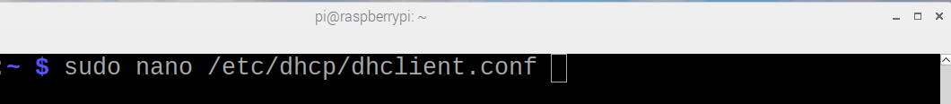
Add the following lines:
option mud-url code 161 = text;

send mud-url = "<insert URL for MUD File here>";
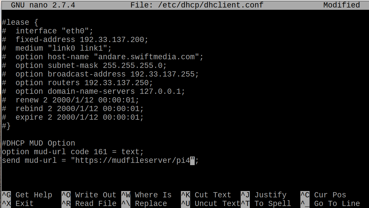
Save and close the file.
Reboot the device:
reboot
Open a terminal.
Execute the dhclient:
sudo dhclient -v
2.5.2.2.2 IoT Application for Testing
The following Python application was created by the NCCoE to enable the devkits to act as basic IoT devices:
#Program: IoTapp.
#Version: 1.0
#Purpose: Provide IoT capabilities to devkit.
#Protocols: MQTT.

#Functionality: Allow remote control of LEDs on connected breadboard.

#Libraries
import paho.mqtt.client as mqttClient
import time
import RPi.GPIO as GPIO

#Global Variables
BrokerAddress = "192.168.1.87" #IP address of Broker(Server), change as needed. Best practice would be a registered domain name that can be queried for appropriate server address.

BrokerPort = "1883" #Default port used by most MQTT Brokers. Would be 1883 if using Transport Encryption with TLS.
ConnectionStatus = "Disconnected" #Status of connection to Broker. Should be either "Connected" or "Disconnected".
LED = 26

#Supporting Functions
def on_connect(client, userdata, flags, rc): #Function for connection status to Broker.
   if rc == 0:

      ConnectionStatus = "Connected to Broker!"
      print(ConnectionStatus)

   else:
      ConnectionStatus = "Connection Failed!"
      print(ConnectionStatus)

def on_message(client, userdata, msg): #Function for parsing message data.
   if "ON" in msg.payload:
      print("ON!")
      GPIO.output(LED, 1)

   if "OFF" in msg.payload:
      print("OFF!")
      GPIO.output(LED, 0)

def MQTTapp():
   client = mqttClient.Client() #New instance.
   client.on_connect = on_connect
   client.on_message = on_message
   client.connect(BrokerAddress, BrokerPort)
   client.loop_start()
   client.subscribe("test")
   try:
      while True:
         me.sleep(1)

   except KeyboardInterrupt:
      print("8")
      client.disconnect()
      client.loop_stop()

#Main Function

def main():

   GPIO.setmode(GPIO.BCM)
   GPIO.setup(LED, GPIO.OUT)

   print("Main function has been executed!")
   MQTTapp()

if \__name_\_ == "__main__":
   main()
2.5.3 IoT Development Kit–u-blox C027-G35
This section details configuration of a u-blox C027-G35, which emits a MUD URL by using DHCP, and a basic IoT application used to test MUD rules.
2.5.3.1 Configuration Overview
This devkit runs the Arm Mbed-OS and is configured to emit a MUD URL during a typical DHCP transaction. It also runs a basic IoT application to test MUD rules.
2.5.3.1.1 Network Configuration
The u-blox C027-G35 is connected to the network over a wired Ethernet connection. The IP address is assigned dynamically by using DHCP.
2.5.3.1.2 Software Configuration
For this build, the u-blox C027-G35 was configured on the Mbed-OS 5.10.4 operating system.
2.5.3.1.3 Hardware Configuration
The hardware used for this devkit is the u-blox C027-G35.
2.5.3.2 Setup
The following subsection describes setting up the u-blox C027-G35 to send a MUD URL in the DHCP transaction and to act as a connected device by establishing network connections to the update server and other destinations.
2.5.3.2.1 DHCP Client Configuration
To add MUD functionality to the Mbed-OS DHCP client, the following two files inside Mbed-OS require modification:
mbed-os/features/lwipstack/lwip/src/include/lwip/prot/dhcp.h
NOT mbed-os/features/lwipstack/lwip/src/include/lwip/dhcp.h
mbed-os/features/lwipstack/lwip/src/core/ipv4/lwip_dhcp.c
Changes to include/lwip/prot/dhcp.h:
Add the following line below the greatest DCHP option number (67) on line 170:

Changes to core/ipv4/lwip_dhcp.c:
Change within container around line 141:
To
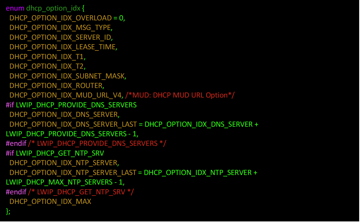
enum dhcp_option_idx(at line 141) before the first#if, add
It should now look like the screenshot below:
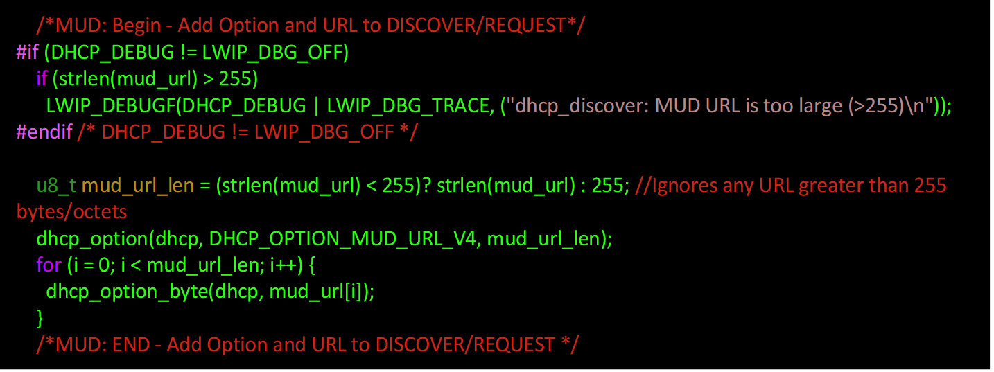
Change within the function around line 975:
To the list of local variables for
static err_t dhcp_discover(struct netif *netif), add the desired MUD URL (www.example.com used here):
Note: The MUD URL must be less than 255 octets/bytes/characters long.
Within
if (result == ERR_OK)after![dhcp_option(dhcp, DHCP_OPTION_PARAMETER_REQUEST_LIST, LWIP_ARRAYSIZE(dhcp_discover_request_options)); for (i = 0; i < LWIP_ARRAYSIZE(dhcp_discover_request_options); i++) { dhcp_option_byte(dhcp, dhcp_discover_request_options[i]); }](../_images/image811.png)
and before:

add:
Change within the function around line 1486:
Within the following function:

Within
switch(op)beforedefault, add the following case (around line 1606):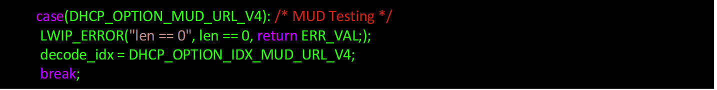
Compile by using the following command:
2.5.3.2.2 IoT Application for Testing
The following application was created by the NCCoE to enable the devkit to test the build as a MUD-capable device:
#include "mbed.h"
#include "EthernetInterface.h"

//DigitalOut led1(LED1);
PwmOut led2(LED2);
Serial pc(USBTX, USBRX);

float brightness = 0.0;

// Network interface
EthernetInterface net;

// Socket demo
int main() {
   int led1 = true;

   for (int i = 0; i < 4; i++) {

      led2 = (led1)? 0.5 : 0.0;

      led1 = !led1;
      wait(0.5);
   }

   for (int i = 0; i < 8; i++) {

      led2 = (led1)? 0.5 : 0.0;

      led1 = !led1;
      wait(0.25);
   }

   for (int i = 0; i < 8; i++) {

      led2 = (led1)? 0.5 : 0.0;

      led1 = !led1;
      wait(0.125);
   }

   TCPSocket socket;
   char sbuffer[] = "GET / HTTP/1.1\r\nHost: www.updateserver.com\r\n\r\n";
   char bbuffer[] = "GET / HTTP/1.1\r\nHost: www.unapprovedserver.com\r\n\r\n";
   int scount, bcount;
   char rbuffer[64];
   char brbuffer[64];
   int rcount, brcount;

   /* By default grab an IP address */
   // Bring up the ethernet interface
   pc.printf("Ethernet socket example\r\n");
   net.connect();
   // Show the network address
   const char *ip = net.get_ip_address();
   pc.printf("IP address is: %s\r\n", ip ? ip : "No IP");
   socket.open(&net);
   /* End of default IP address */

   pc.printf("Press U to turn LED1 brightness up, D to turn it down, G to get IP, R to release IP, H for HTTP request, B for blocked HTTP request\r\n");

   while(1) {

      char c = pc.getc();

      if((c == 'u') && (brightness < 0.5)) {
         brightness += 0.01;
         led2 = brightness;
      }

      if((c == 'd') && (brightness > 0.0)) {
         brightness -= 0.01;
         led2 = brightness;
      }

      if(c == 'g'){
         // Bring up the ethernet interface
         pc.printf("Sending DHCP Request...\r\n");
         net.connect();
         // Show the network address
         const char *ip = net.get_ip_address();
         pc.printf("IP address is: %s\r\n", ip ? ip : "No IP");
      }

      if(c == 'r'){
         socket.close();
         net.disconnect();
         pc.printf("IP Address Released\r\n");
      }

      if(c == 'h'){
         pc.printf("Sending HTTP Request...\r\n");
         // Open a socket on the network interface, and create a TCP connection
         socket.open(&net);
         socket.connect("*www.updateserver.com*", 80);
         // Send a simple http request
         scount = socket.send(sbuffer, sizeof sbuffer);
         pc.printf("sent %d [%.*s]\r\n", scount, strstr(sbuffer, "\r\n")-sbuffer, sbuffer);
         // Receive a simple http response and print out the response line
         rcount = socket.recv(rbuffer, sizeof rbuffer);
         pc.printf("recv %d [%.*s]\r\n", rcount, strstr(rbuffer, "\r\n")-rbuffer, rbuffer);
         socket.close();
      }

      if(c == 'b'){
         pc.printf("Sending Blocked HTTP Request...\r\n");
         // Open a socket on the network interface, and create a TCP connection
         socket.open(&net);
         socket.connect("www.unapprovedserver.com", 80);
         // Send a simple http request
         bcount = socket.send(bbuffer, sizeof bbuffer);
         pc.printf("sent %d [%.*s]\r\n", bcount, strstr(bbuffer, "\r\n")-bbuffer, bbuffer);
         // Receive a simple http response and print out the response line
         brcount = socket.recv(brbuffer, sizeof brbuffer);
         pc.printf("recv %d [%.*s]\r\n", brcount, strstr(brbuffer, "\r\n")-brbuffer, brbuffer);
         socket.close();
      }

   }

}
2.5.4 IoT Devices–Non-MUD-Capable
This section details configuration of non-MUD-capable IoT devices attached to the implementation network. These include several types of devices, such as cameras, mobile phones, lighting, a connected assistant, a printer, a baby monitor, a wireless access point, and a digital video recorder. These devices did not emit a MUD URL or have MUD capabilities of any kind.
2.5.4.1 Configuration Overview
These non-MUD-capable IoT devices are unmodified and still retain the default manufacturer configurations.
2.5.4.1.1 Network Configuration
These IoT devices are configured to obtain an IP address via DHCP.
2.5.4.1.2 Software Configuration
The software on these devices is configured according to standard manufacturer instructions.
2.5.4.1.3 Hardware Configuration
The hardware used in these devices is unmodified from manufacturer specifications.
2.5.4.2 Setup
These devices were set up according to the manufacturer instructions and connected to the Cisco switch via Ethernet cable or connected wirelessly through the wireless access point.
2.5.4.2.1 DHCP Client Configuration
These IoT devices used the default DHCP clients provided by the original manufacturer and were not modified in any way.
2.6 Update Server
This section describes how to implement a server that will act as an update server. It will attempt to access and be accessed by the IoT device, in this case one of the development kits we built in the lab.
2.6.1 Update Server Overview
The update server is an Apache web server that hosts mock software update files to be served as software updates to our IoT device devkits. When the server receives an http request, it sends the corresponding update file.
2.6.2 Configuration Overview
The following subsections document the software, hardware, and network requirements for the update server.
2.6.2.1 Network Configuration
The IP address was statically assigned.
2.6.2.2 Software Configuration
For this build, the update server was configured on the Ubuntu 18.04 LTS operating system.
2.6.2.3 Hardware Configuration
The update server was hosted in the NCCoE’s virtual environment, functioning as a cloud service.
2.6.3 Setup
The Apache web server was set up by using the official Apache documentation at https://httpd.apache.org/docs/current/install.html. After completing the process, the SSL/TLS encryption was set up by using the digital certificate and key obtained from DigiCert. This was set up by using the official Apache documentation, found at https://httpd.apache.org/docs/current/ssl/ssl_howto.html.
The following configurations were made to the server to host the update file:
Open a terminal.
Change directories to the Hypertext Markup Language (HTML) folder:
cd /var/www/html/
Create the update file. (Note: this is a mock update file.)
touch IoTsoftwareV2.tar.gz
2.7 Unapproved Server
This section describes how to implement a server that will act as an unapproved server. It will attempt to access and to be accessed by an IoT device, in this case one of the MUD-capable devices on the implementation network.
2.7.1 Unapproved Server Overview
The unapproved server is an internet host that is not explicitly authorized in the MUD file to communicate with the IoT device. When the IoT device attempts to connect to this server, the router or switch should not allow this traffic because it is not an approved internet service as defined by the corresponding MUD file. Likewise, when the server attempts to connect to the IoT device, this traffic should be denied at the router or switch.
2.7.2 Configuration Overview
The following subsections document the software, hardware, and network configurations for the unapproved server.
2.7.2.1 Network Configuration
The unapproved server hosts a web server that is accessed via Transmission Control Protocol (TCP) port 80. Any applications that request access to this server need to be able to connect on this port. Use firewall-cmd, iptables, or any other system utility for manipulating the firewall to open this port.
2.7.2.2 Software Configuration
For this build, the CentOS 7 OS was leveraged with an Apache web server.
2.7.2.3 Hardware Configuration
The unapproved server was hosted in the NCCoE’s virtual environment, functioning as a cloud service. The IP address was statically assigned.
2.7.3 Setup
The following subsection describes the setup process for configuring the unapproved server.
2.7.3.1 Apache Web Server
The Apache web server was set up by using the official Apache documentation at https://httpd.apache.org/docs/current/install.html. SSL/TLS encryption was not used for this server.
2.8 MQTT Broker Server
2.8.1 MQTT Broker Server Overview
For this build, the open-source tool Mosquitto was used as the MQTT broker server. The server communicates publish and subscribe messages among multiple clients. For our implementation, this server allows mobile devices set up with the appropriate application to communicate with the MQTT-enabled IoT devices in the build. The messages exchanged by the devices are on and off messages, which allow the mobile device to control the LED light on the MQTT-enabled IoT device.
2.8.2 Configuration Overview
The following subsections document the software, hardware, and network requirements for the MQTT broker server.
2.8.2.1 Network Configuration
The MQTT broker server was hosted in the NCCoE’s virtual environment, functioning as a cloud service. The IP address was statically assigned.
The server is accessed via TCP port 1883. Any clients that require access to this server need to be able to connect on this port. Use firewall-cmd, iptables, or any other system utility for manipulating the firewall to open this port.
2.8.2.2 Software Configuration
For this build, the MQTT broker server was configured on an Ubuntu 18.04 LTS operating system.
2.8.2.3 Hardware Configuration
This server was hosted in the NCCoE’s virtual environment, functioning as a cloud service. The IP address was statically assigned.
2.8.3 Setup
In this section we describe setting up the MQTT broker server to communicate messages to and from the controlling application and the IoT device.
2.8.3.1 Mosquitto Setup
Install the open-source MQTT broker server, Mosquitto, by entering the following command:
sudo apt-get update && sudo apt-get install mosquitto
Following the installation, this implementation leveraged the default configuration of the Mosquitto server. The MQTT broker server was set up by using the official Mosquitto documentation at https://mosquitto.org/man/.
2.9 Forescout–IoT Device Discovery
This section describes how to implement Forescout’s appliance and enterprise manager to provide device discovery on the network.
2.9.1 Forescout Overview
The Forescout appliance discovers, catalogs, profiles, and classifies the devices that are connected to the demonstration network. When a device is added to or removed from the network, the Forescout appliance is updated and actively monitors these devices on the network. The administrator will be able to manage multiple Forescout appliances from a central point by integrating the appliance with the enterprise manager.
2.9.2 Configuration Overview
The following subsections document the software, hardware, and network requirements for the Forescout appliance and enterprise manager.
2.9.2.1 Network Configuration
The virtual Forescout appliance was hosted on VLAN 2 of the Cisco switch. It was set up with just the monitor interface. The network configuration for the Forescout appliance was completed by using the official Forescout documentation at https://docs.forescout.com/bundle/Installation_Guide_8.0.1/resource/Installation_Guide_8.0.1.pdf (see Chapters 2 and 8).
The virtual enterprise manager was hosted in the virtual environment that is shared across each build.
2.9.2.2 Software Configuration
The build leveraged a virtual Forescout appliance VCT-R version 8.0.1 along with a virtual enterprise manager VCEM-05 version 8.0.1. Both virtual appliances were built on a Linux OS supported by Forescout.
Forescout provides software for managing the appliances on the network. The Forescout console is software that allows management of the Forescout appliance/enterprise manager and visualization of the data gathered by the appliances.
2.9.2.3 Hardware Configuration
The build leveraged a virtual Forescout appliance, which was set up in the lab environment on a dedicated machine hosting the local virtual machines in Build 1.
The virtual enterprise manager was hosted in the NCCoE’s virtual environment with a static IP assignment.
2.9.3 Setup
In this section we describe setting up the virtual Forescout appliance and the virtual enterprise manager.
2.9.3.1 Forescout Appliance Setup
The virtual Forescout appliance was set up by using the official Forescout documentation at https://docs.forescout.com/bundle/Installation_Guide_8.0.1/resource/Installation_Guide_8.0.1.pdf (see Chapters 3 and 8).
2.9.3.2 Enterprise Manager Setup
The enterprise manager was set up by using the official Forescout documentation at https://docs.forescout.com/bundle/Installation_Guide_8.0.1/resource/Installation_Guide_8.0.1.pdf (see Chapters 4 and 8).
Using the enterprise manager, we configured the following modules:
Endpoint
Network
Authentication
Core Extension
Device Profile Library—https://www.Forescout.com/wp-content/uploads/2018/04/CounterACT_Device_Profile_Library.pdf
IoT Posture Assessment Library—https://www.Forescout.com/wp-content/uploads/2018/04/CounterACT_IoT_Posture_Assessment_Library-1.pdf
Network Interface Card (NIC) Vendor DB—https://www.Forescout.com/wp-content/uploads/2018/04/CounterACT_NIC_Vendor_DB_17.0.12.pdf
Windows Applications—https://www.Forescout.com/wp-content/uploads/2018/04/CounterACT_Windows_Applications.pdf
Windows Vulnerability Database (DB)—https://www.Forescout.com/wp-content/uploads/2018/04/CounterACT_Windows_Vulnerability_DB_18.0.2.pdf
eyeExtend Connect Module - https://docs.forescout.com/bundle/connect-module-1-7-rn/page/connect-module-1-7-rn.About-eyeExtend-Connect-Module-1.7.html
3 Build 2 Product Installation Guides
This section of the practice guide contains detailed instructions for installing and configuring the products used to implement Build 2. For additional details on Build 2’s logical and physical architectures, please refer to NIST SP 1800-15B.
3.1 Yikes! MUD Manager
This section describes the Yikes! MUD manager version v1.1.3, which is a software package deployed on the Yikes! router. It should not require configuration as it should be fully functioning upon connecting the Yikes! router to the network.
3.1.1 Yikes! MUD Manager Overview
The Yikes! MUD manager is a software package supported by MasterPeace within the Yikes! physical router. The version of the Yikes! router used in this implementation supports IoT devices that leverage DHCP as their default MUD emission method.
3.1.2 Configuration Overview
At this implementation, no additional network, software, or hardware configuration was required to enable the Yikes! MUD manager capability on the Yikes! router.
3.1.3 Setup
At this implementation, no setup was required to enable the Yikes! MUD manager capability on the Yikes! router. See the Yikes! Router section for details on the router setup.
3.2 MUD File Server
3.2.1 MUD File Server Overview
For this build, the NCCoE leveraged a MUD file server hosted by MasterPeace. This file server hosts MUD files along with their corresponding signature files for the MUD-capable IoT devices used in Build 2. The MUD file server is responsible for serving the MUD file and the corresponding signature file upon request from the MUD manager. These files were created by the NCCoE and provided to MasterPeace to host due to the Yikes! cloud component requirement that the MUD file server be internet accessible to display the contents of the MUD file in the Yikes! user interface (UI).
To build an on-premises MUD file server and to create MUD files for MUD-capable IoT devices, please follow the instructions in Build 1’s MUD File Server section.
3.3 Yikes! DHCP Server
This section describes the Yikes! DHCP server, which should also be fully functional out of the box and should not require any modification upon receipt.
3.3.1 Yikes! DHCP Server Overview
The Yikes! DHCP server is MUD capable and, like the Yikes! MUD manager and Yikes! threat-signaling agent, is a logical component within the Yikes! router. In addition to dynamically assigning IP addresses, it recognizes the DHCP option (161) and logs DHCP events that include this option to a log file. This log file is monitored by the Yikes! MUD manager, which is responsible for handling the MUD requests.
3.3.2 Configuration Overview
At this implementation, no additional network, software, or hardware configuration was required to enable the Yikes! DHCP server capability on the Yikes! router.
3.3.3 Setup
At this implementation, no additional setup was required.
3.4 Yikes! Router
This section describes how to implement and configure the Yikes! router, which requires minimal configuration from a user standpoint.
3.4.1 Yikes! Router Overview
The Yikes! router is a customized original equipment manufacturer product, which at implementation was a preproduction product. It is a self-contained router, Wi-Fi access point, and firewall that communicates locally with Wi-Fi devices and wired devices. The Yikes! router leveraged in this implementation was developed on an OpenWRT base router with the Yikes! capabilities added on. The Yikes! router hosts all the software necessary to enable a MUD infrastructure on premise. It also communicates with the Yikes! cloud and threat-signaling services to support additional capabilities in the network.
At this implementation, the Yikes! MUD manager, DHCP server, and GCA threat-signaling components all reside on the Yikes! router and are configured to function without any additional configuration.
3.4.2 Configuration Overview
3.4.2.1 Network Configuration
Implementation of a Yikes! router requires an internet source such as a Digital Subscriber Line (DSL) or cable modem.
3.4.2.2 Software Configuration
At this implementation, no additional software configuration was required to set up the Yikes! router.
3.4.2.3 Hardware Configuration
At this implementation, no additional hardware configuration was required to set up the Yikes! router.
3.4.3 Setup
As stated earlier, the version of the Yikes! router used in Build 2 was preproduction, so MasterPeace may have performed some setup and configuration steps that are not documented here. Those additional steps, however, are not expected to be required to set up the production version of the router. The following setup steps were performed:
Unbox the Yikes! router and provided accessories.
Connect the Yikes! router’s wide area network port to an internet source (e.g., cable modem or DSL).
Plug the power supply into the Yikes! router.
Power on the Yikes! router.
After powering on the router, the network password must be provided so the router can authenticate itself to the network. In addition, best security practices (not documented here), such as changing the router’s administrative password, should be followed in accordance with the security policies of the user.
3.5 DigiCert Certificates
DigiCert’s CertCentral web-based platform allows provisioning and management of publicly trusted X.509 certificates for a variety of purposes. After establishing an account, clients can log in, request, renew, and revoke certificates by using only a browser. For Build 2, the Premium Certificate created in Build 1 was leveraged for signing the MUD files. To request and implement DigiCert certificates, follow the documentation in Build 1’s DigiCert Certificates section and subsequent sections.
3.6 IoT Devices
3.6.1 IoT Development Kits—Linux Based
3.6.1.1 Configuration Overview
This section provides configuration details for the Linux-based IoT development kits used in the build, which emit MUD URLs by using DHCP. It also provides information regarding a basic IoT application used to test the MUD process.
3.6.1.1.1 Network Configuration
The devkits are connected to the network over both a wired Ethernet connection and wirelessly. The IP address is assigned dynamically by using DHCP.
3.6.1.1.2 Software Configuration
For this build, Raspberry Pi is configured on Raspbian 9, the Samsung ARTIK 520 is configured on Fedora 24, the NXP i.MX 8m is configured on Yocto Linux, and the BeagleBone Black is configured on Debian 9.5. The devkits also utilized a variety of DHCP clients, including dhcpcd and dhclient (see Build 1’s IoT Development Kits–Linux Based section for dhclient configurations). This build introduced dhcpcd as a method for emitting a MUD URL for all devkits in this build, apart from the NXP i.MX 8m, which leveraged dhclient. Dhcpcd is provided with many Linux distributions and can be installed using a preferred package manager if not currently present.
3.6.1.1.3 Hardware Configuration
The hardware used for these devkits included the Raspberry Pi 3 Model B, Samsung ARTIK 520, NXP i.MX 8m, and BeagleBone Black.
3.6.1.2 Setup
The following subsection describes setting up the devkits to send a MUD URL during the DHCP transaction using dhcpcd as the DHCP client on the Raspberry Pi. For dhclient instructions, see Build 1’s Setup and DHCP Client Configuration sections.
3.6.1.2.1 DHCP Client Configuration
These devkits utilized dhcpcd version 7.2.3. Configuration consisted of adding the following line to the file located at /etc/dhcpcd.conf:
mudurl https://<example-url>
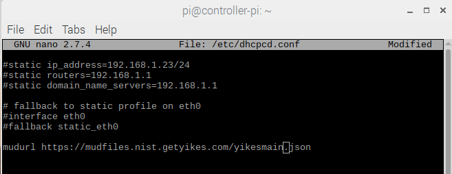
3.7 Update Server
Build 2 leveraged the preexisting update server that is described in Build 1’s Update Server section. To implement a server that will act as an update server, see the documentation in Build 1’s Update Server section. The update server will attempt to access and be accessed by the IoT device, which, in this case, is one of the development kits we built in the lab.
3.8 Unapproved Server
Build 2 leverages the preexisting unapproved server that is described in Build 1’s Unapproved Server section. To implement a server that will act as an unapproved server, see the documentation in Build 1’s Unapproved Server section. The unapproved server will attempt to access and to be accessed by an IoT device, which, in this case, is one of the MUD-capable devices on the implementation network.
3.9 Yikes! IoT Device Discovery, Categorization, and Traffic Policy Enforcement (Yikes! Cloud and Yikes! Mobile Application)
This section describes how to implement and configure Yikes! IoT device discovery, categorization, and traffic policy enforcement, which is a capability supported by the Yikes! router, Yikes! cloud, and Yikes! mobile application.
3.9.1 Yikes! IoT Device Discovery, Categorization, and Traffic Policy Enforcement Overview
The Yikes! router provides an IoT device discovery service for Build 2. Yikes! discovers, inventories, profiles, and classifies devices connected to the local network consistent with each device’s type and allows traffic enforcement policies to be configured by the user through the Yikes! mobile application.
Yikes! isolates every device on the network so that, by default, no device is permitted to communicate with any other device. Devices added to the network are automatically identified and categorized based on information such as DHCP header, MAC address, operating system, manufacturer, and model.
Using the Yikes! mobile application, users can define fine-grained device filtering. The enforcement can be set to enable specific internet access (north/south) and internal network access to specific devices (east/west) as determined by category-specific rules.
3.9.2 Configuration Overview
3.9.2.1 Network Configuration
No network configurations outside Yikes! router network configurations are required to enable this capability.
3.9.2.2 Software Configuration
MasterPeace performed some software configuration on the Yikes! router after it was deployed as part of Build 2. Aside from this, no additional software configuration was required to support device discovery. When the production version of the Yikes! router is available, it is not expected to require configuration. The Yikes! mobile application was still in development during deployment. The build used the web-based Yikes! mobile application from a laptop in the lab environment to display and configure device information and traffic policies.
3.9.2.3 Hardware Configuration
At this implementation, the Yikes! mobile application was not published in an application store. For this reason, a desktop was leveraged to load the web page hosting the “mobile application.”
3.9.3 Setup
Once devices have been added to the network on the Yikes! router, they will appear in the Yikes! cloud inventory, which is accessible via the Yikes! mobile application. At this implementation, the Yikes! mobile application and the processes associated with the Yikes! cloud service were under development. It is possible that the design of the UI and the workflow will change for the final implementation of the mobile application.
3.9.3.1 Yikes! Router and Account Cloud Registration
At this implementation, the Yikes! router and cloud account registration processes were under development. As a result, this section will not describe how to associate a Yikes! router with a Yikes! cloud instance. The steps below show the process for account registration at this implementation.
Open a browser and access the Yikes! UI. (Note: in the preproduction version of the router, accessing the UI required inputting a URL provided by MasterPeace.)
Click on the Register button to sign up for an account:
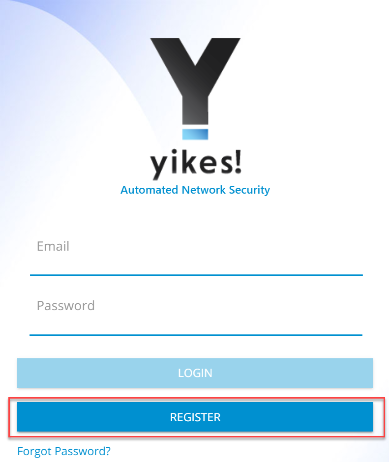
Populate the requested information for the account: First Name, Last Name, Email, and Password. Click Sign Up:
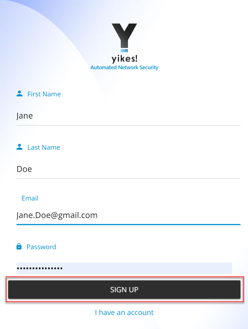
Note: There will be additional steps related to associating the Yikes! router with the Yikes! account being created. However, at this implementation, this process was still under development.
Once the account is approved and linked to the Yikes! router, Log in with the credentials created in step 3:
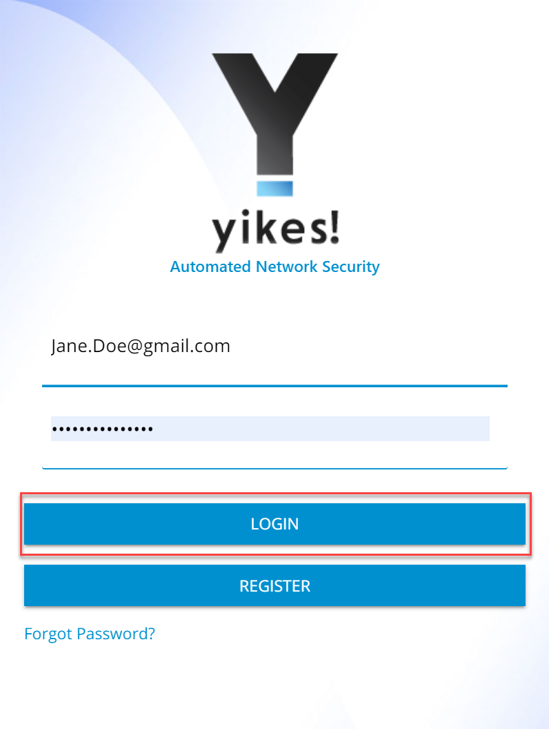
The home screen will show the network overview:
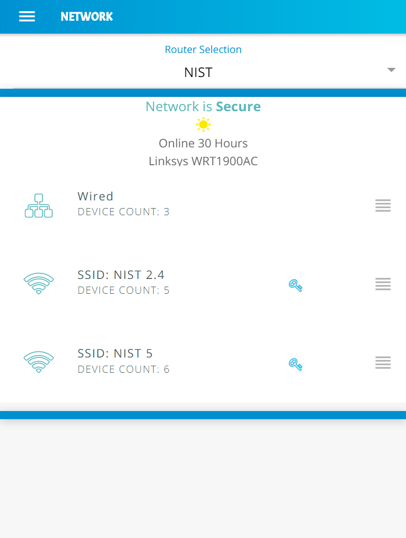
3.9.3.2 Yikes! MUD-Capable IoT Device Discovery
This section details the Yikes! MUD-capable IoT device discovery capability. This feature is accessible through the Yikes! mobile application and identifies all MUD-capable IoT devices that are connected to the network.
Open the menu pane in the UI:
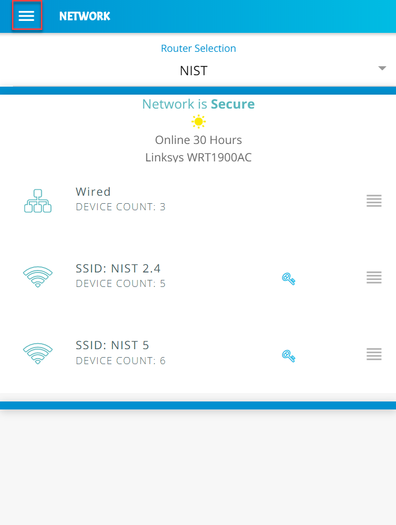
Click the Devices button to open the devices menu:
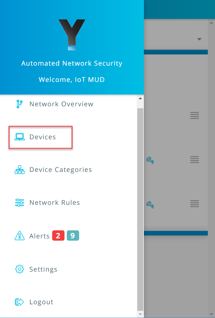
Click the MUD tab to switch from the ALL device view to review the MUD-capable IoT devices connected to the network:
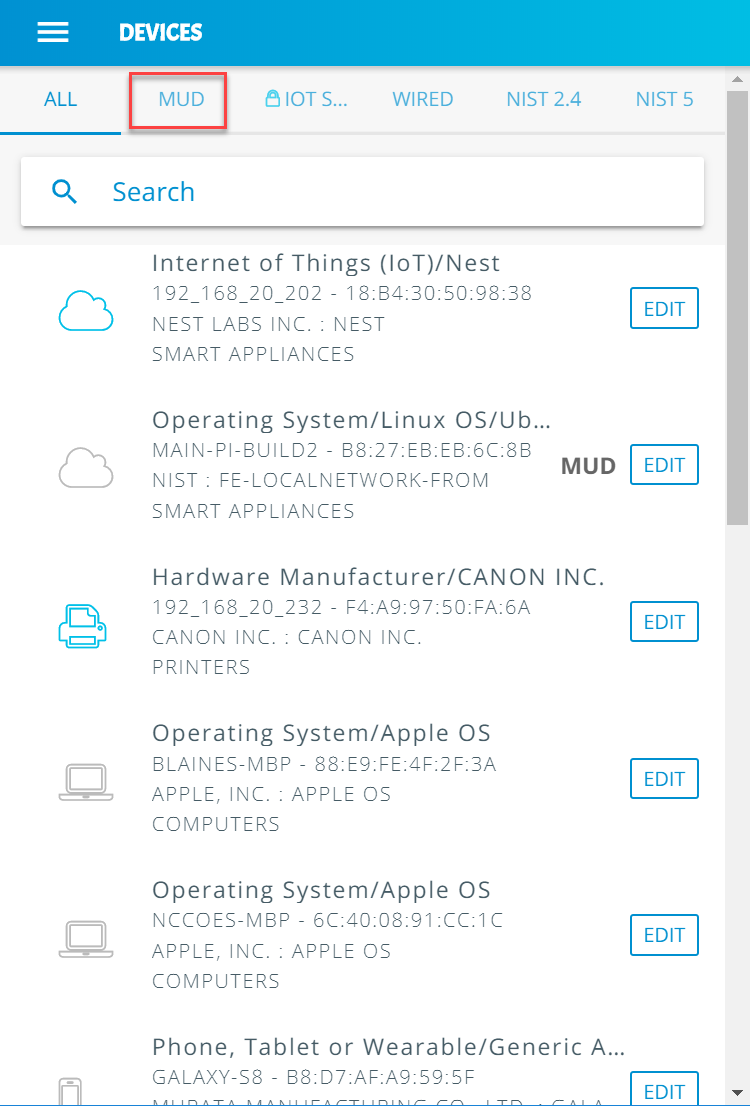
All MUD-capable devices on the network will have the MUD label as seen below:
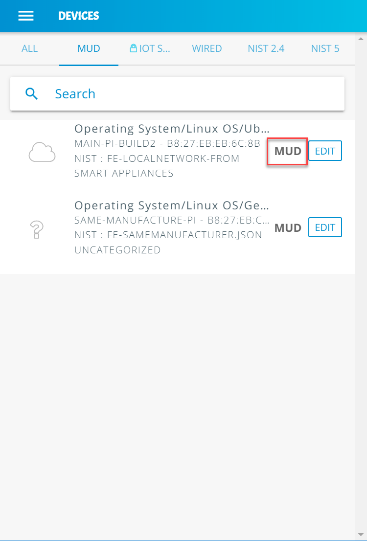
3.9.3.3 Yikes! Alerts
This section details the Yikes! alerting capability. This feature is accessible through the Yikes! mobile application and notifies users when new devices have been connected to the network. Additionally, this feature alerts the user when new devices are not recognized as known devices and are placed in the uncategorized device category by the Yikes! cloud.
From the Yikes! mobile application, the user can edit the information about the device (e.g., name, make, and model) and modify the device’s category or can choose to ignore the alert by removing the notification.
Open the menu pane in the UI:
Click Alerts to open the Alerts menu:
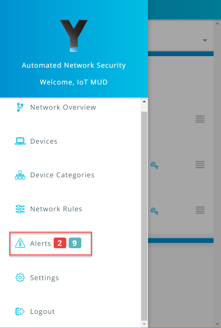
Select a device to edit the device information and category by clicking Edit Device:
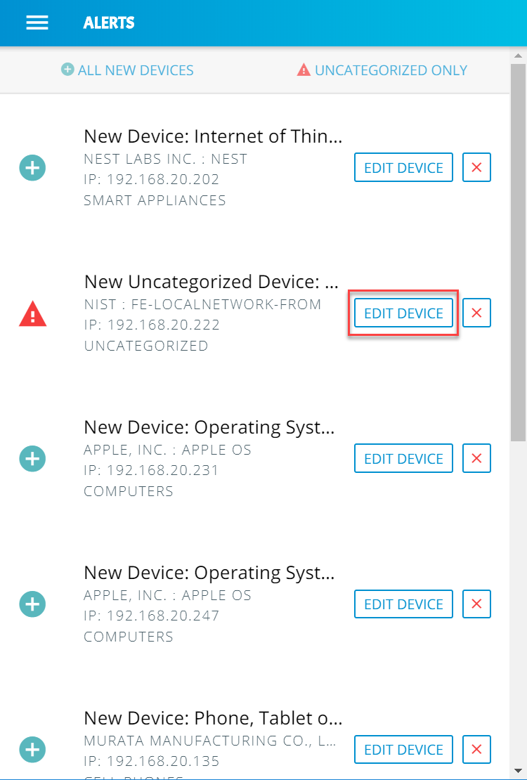
Modify the Category of the device by clicking the device’s current category:
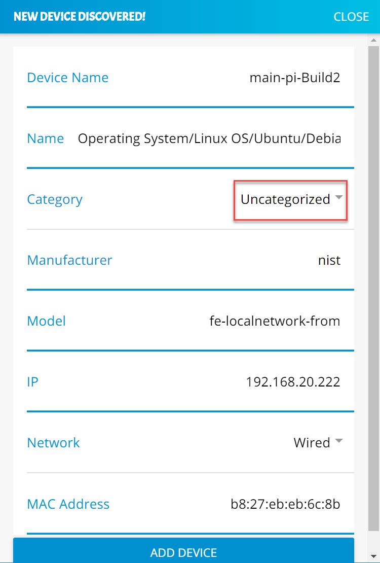
Select the desired category, in this case Smart Appliances, and click OK:
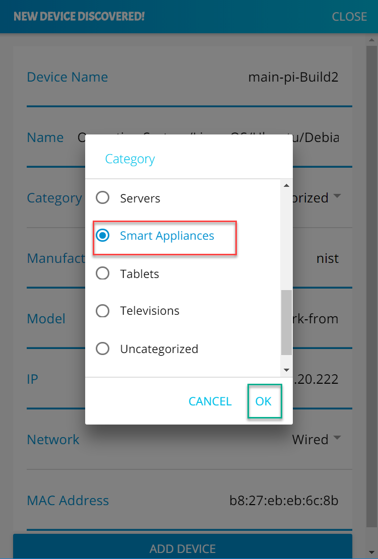
The device Category will update to reflect the new selection. Click Add Device to complete the process:
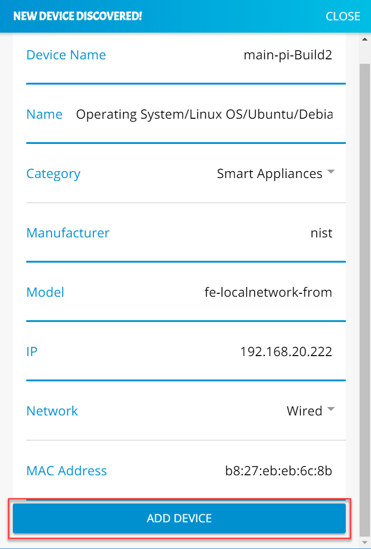
The alerts menu will update and no longer include the device that was just modified and added:
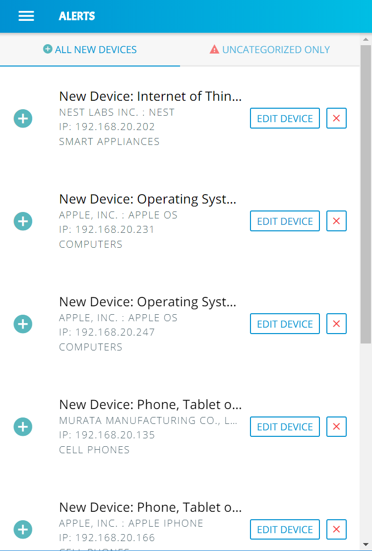
3.9.3.4 Yikes! Device Categories and Setting Rules
The Yikes! mobile application provides the capability to view predefined device categories and set rules for local communication between categories of devices on the local network and internet rules for all devices in a selected category.
Click the menu bar to open the menu pane:
Click the Device Categories option to view all device categories:
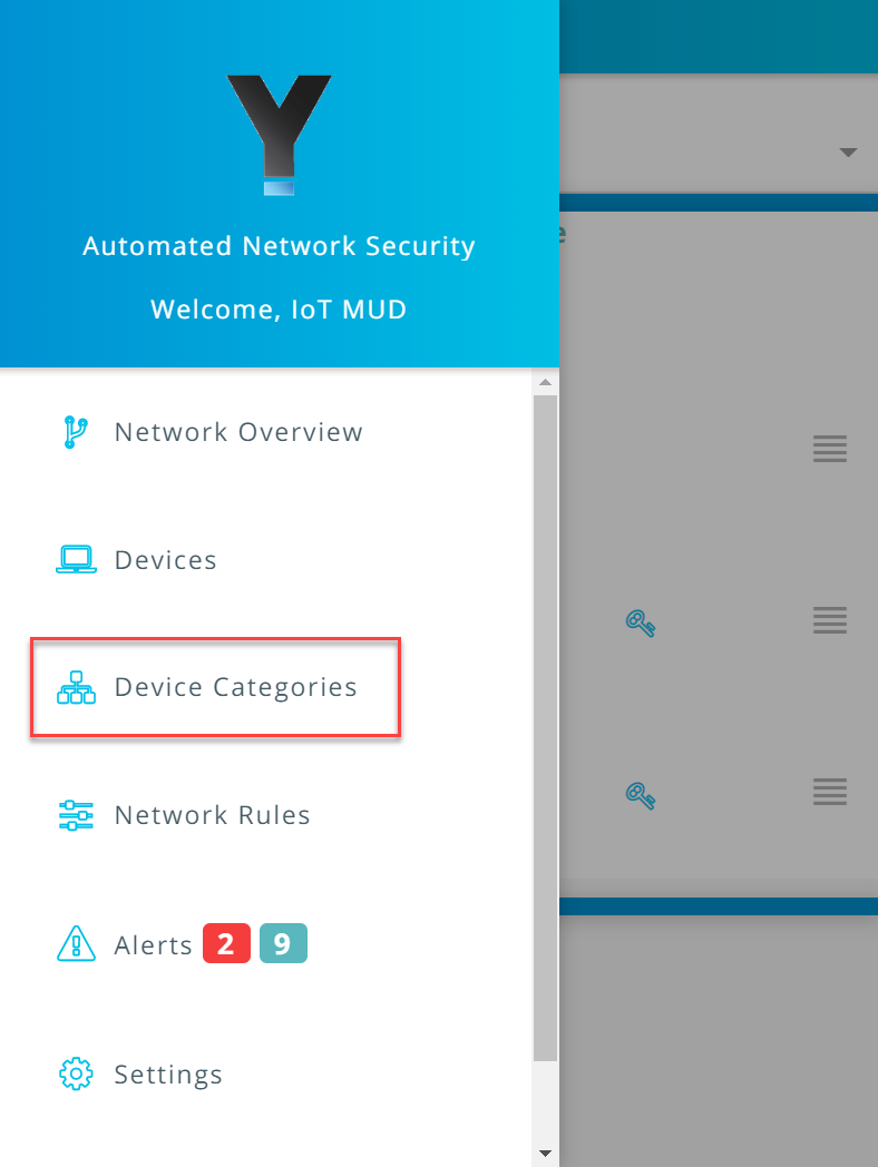
Select the category of device to view and configure rules:
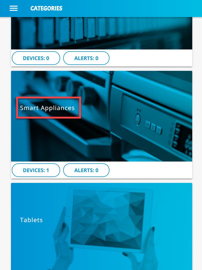
Modify local rules by clicking on the category of devices with which the selected category is permitted to communicate:
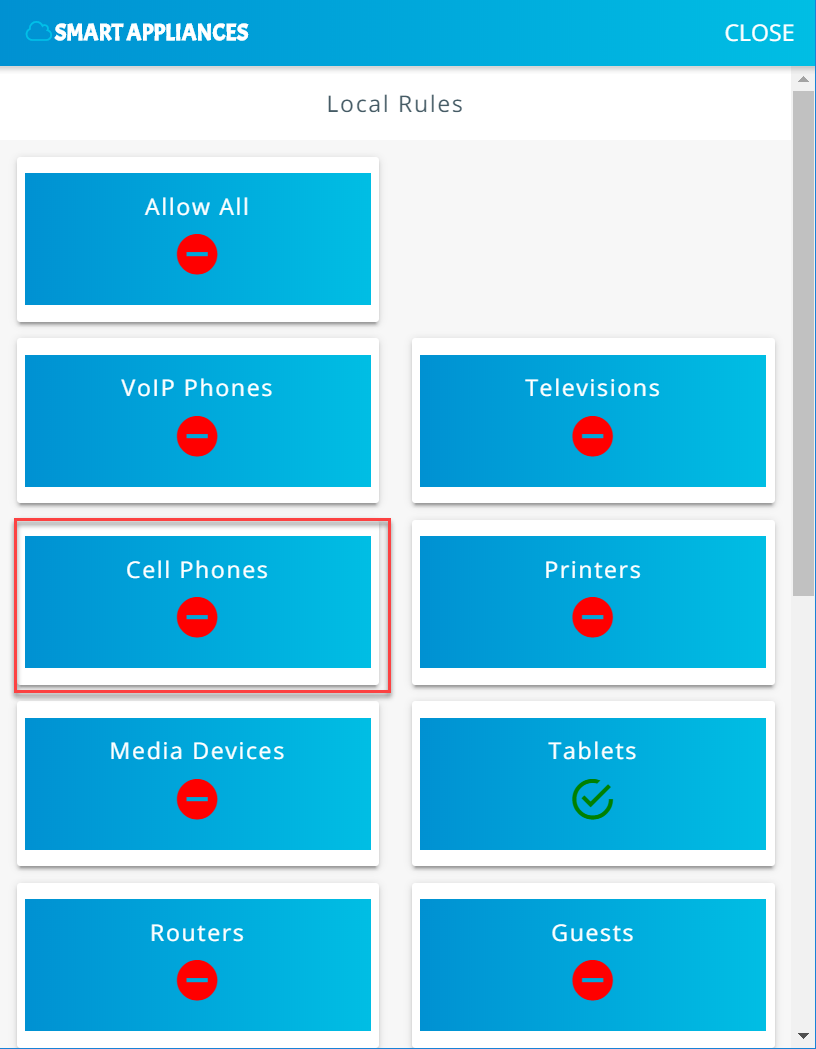
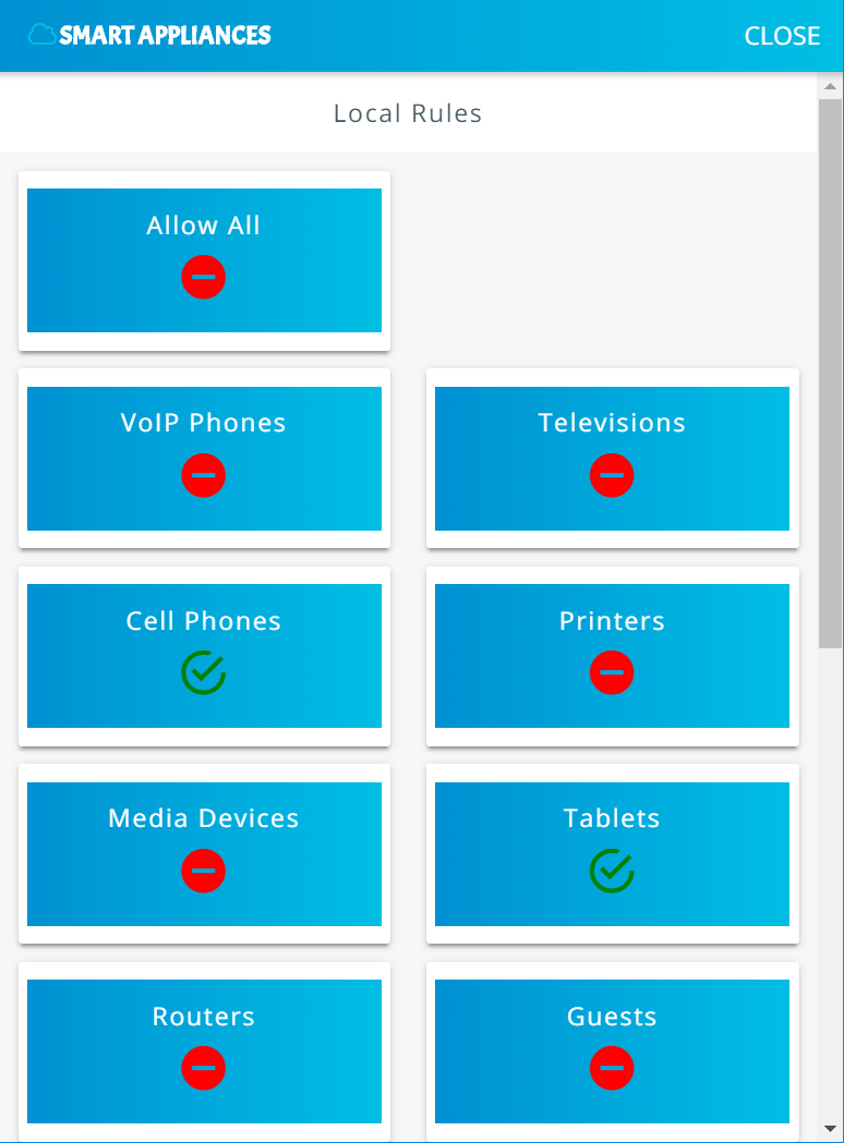
Scroll to the bottom of the page to view the current Internet Rules for this category, and change the permissions by clicking on IoT Specific Sites:
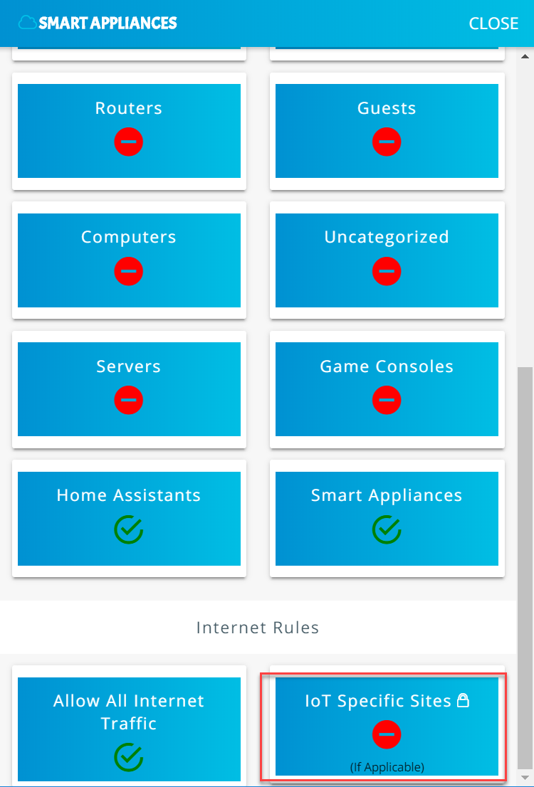
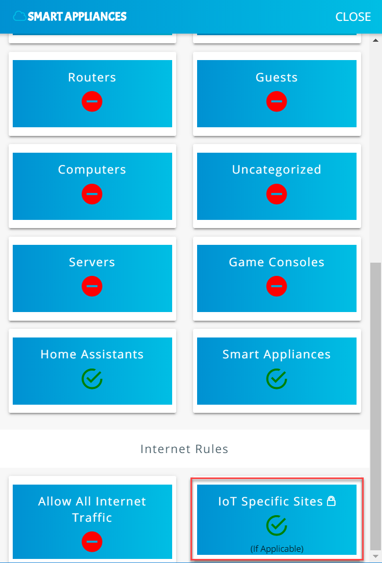
Smart appliances should now be permitted to communicate locally to Smart Appliances, Home Assistants, Tablets, Cell Phones, and, externally, to IoT Specific Sites.
3.9.3.5 Yikes! Network Rules
The Yikes! mobile application allows reviewing the rules that have been implemented on the network. These rules are divided into two main sections: Local Rules and Internet Rules. Local rules display the local communications permitted for each category of devices. Internet rules display the internet communications permitted for each category of devices. This section reviews the rules defined for Smart Appliances in Yikes! Device Categories and Setting Rules UI:
Click Network Rules to navigate to the rules menu:
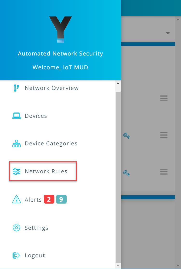
Click Local Rules to view the permitted local communications for each device category:
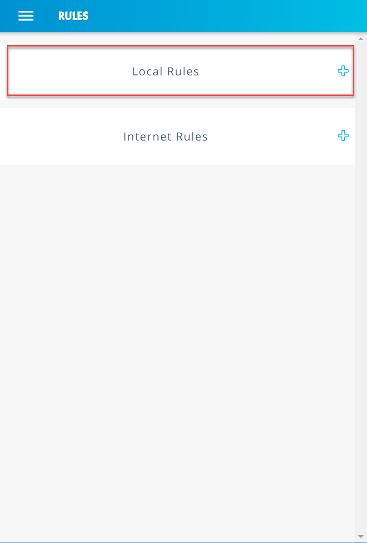
Scroll down to view the local rules for the Smart Appliances category:
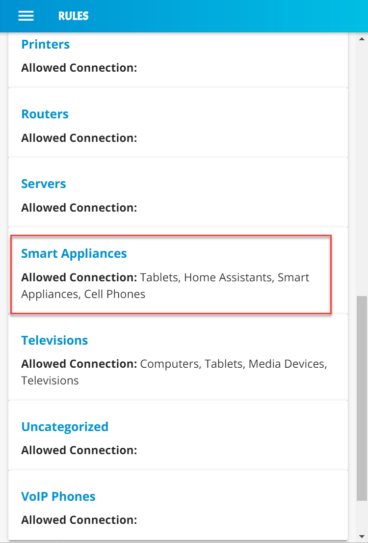
Minimize the rules by clicking the Local Rules button:
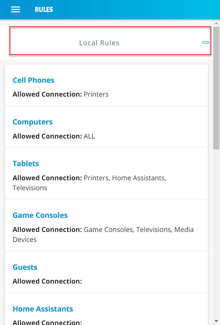
Expand the rules that show internet rules for device categories by clicking Internet Rules:
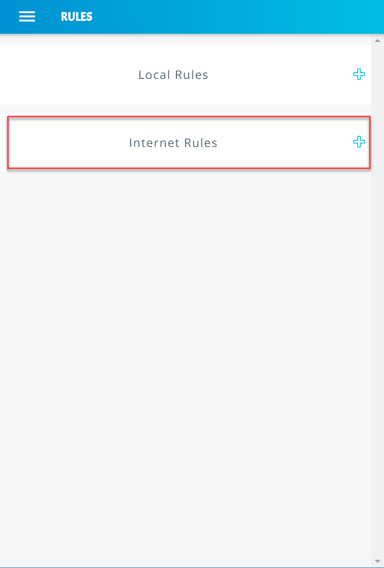
Scroll down to view the internet rules for the Smart Appliances category:
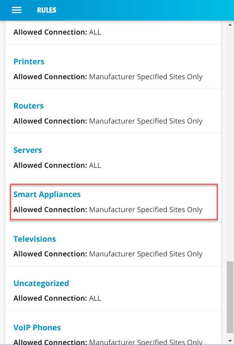
Minimize the rules by clicking the Internet Rules button:
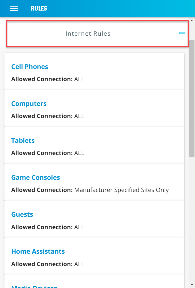
3.10 GCA Quad9 Threat Signaling in Yikes! Router
This section describes the threat-signaling service provided by GCA in the Yikes! router. This capability should not require configuration because the Quad9 Active Threat Response (Q9Thrt) open-source software should be fully functional when the Yikes! router to connects to the network. Please see the Q9Thrt GitHub page for details on this software: https://github.com/osmud/q9thrt#q9thrt.
3.10.1 GCA Quad9 Threat Signaling in Yikes! Router Overview
The GCA Q9Thrt leverages DNS traffic by using Quad9 DNS services and threat intelligence from ThreatSTOP. As detailed in NIST SP 1800-15B, Q9Thrt is integrated into the Yikes! router and relies on the availability of three third-party services in the cloud: Quad9 DNS service, Quad9 threat API, and ThreatSTOP threat MUD file server. The Yikes! router is integrated with GCA Q9Thrt capabilities implemented, configured, and enabled out of the box.
3.10.2 Configuration Overview
At this implementation, no additional network, software, or hardware configuration was required to enable GCA Q9Thrt on the Yikes! router.
3.10.3 Setup
At this implementation, no additional setup was required to enable GCA Q9Thrt on the Yikes! router. See the Yikes! Router section for details on the router setup.
To take advantage of threat signaling, the Yikes! router uses the Quad9 DNS services for domain name resolution. GCA Quad threat signaling depends upon the Quad9 DNS services to be up and running. The Quad9 threat API must also be available to provide the Yikes! router with information regarding specific threats. In addition, for any given threat that is found, the MUD file server provided by the threat intelligence service that has flagged that threat as potentially dangerous must also be available. These are third-party services that GCA Q9Thrt relies upon to be set up, configured, and available.
It is possible to implement the Q9Thrt feature onto a non-Yikes! router. To integrate the Q9Thrt feature onto an existing router, see the open-source software on GitHub: https://github.com/osmud/q9thrt.
This software was designed for and has been integrated successfully using the OpenWRT platform but has the potential to be integrated into various networking environments. Instructions on how to deploy Q9thrt onto an existing router can be found on https://github.com/osmud/q9thrt#q9thrt.
4 Build 3 Product Installation Guides
This section of the practice guide contains detailed instructions for installing, configuring, and integrating the products used to implement Build 3. For additional details on Build 3’s logical and physical architectures, please refer to NIST SP 1800-15B.
4.1 Product Installation
4.1.1 DigiCert Certificates
DigiCert’s CertCentral web-based platform allows provisioning and management of publicly trusted X.509 certificates for a variety of purposes. After establishing an account, clients can log in, request, renew, and revoke certificates by using only a browser. For Build 3, the Premium Certificate created in Build 1 was leveraged for signing the MUD files. Additionally, this implementation leveraged a standard SSL certificate to secure the cloud servers. You will need to request standard SSL certificates for each of the servers in your implementation. For this build we requested standard SSL certificates for two servers—the MUD file server and the Micronets service provider cloud server. To request and implement DigiCert certificates, follow the documentation in Build 1’s DigiCert Certificates section and subsequent sections.
Once you have received the requested certificates, you can store these on the respective servers in your desired location. For this demonstration, we simply stored them in the workspace directory on the appropriate servers, but it is likely these would be stored in the /usr/lib or /etc/lib directories.
4.1.2 MUD Manager
This section describes the CableLabs MUD manager, which, for this implementation, is a cloud-provided service. This implementation leveraged the nccoe-build-3 branch of CableLabs MUD manager Git release. This service can be hosted by the implementer or another party. This documentation describes setting up your own MUD manager.
4.1.2.1 MUD Manager Overview
The CableLabs MUD manager is used by the Micronets Manager as a utility service to retrieve MUD files from a passed URL, parse the MUD file, and produce device communication restriction declarations that can be passed to the associated Micronets Gateway Service.
This Micronets MUD manager is hosted in the service provider cloud and for this implementation is on the same server as the other Micronets services. The MUD manager is responsible for retrieving MUD files and their associated signature files and executing verification as outlined in the MUD specification. It generates the ACLs for the device based on the MUD file and provides this information to the Micronets Manager.
4.1.2.2 Configuration Overview
The following subsections document the software and network configurations for the MUD manager. Please note that the MUD manager, Micronets Manager, Websocket Proxy, MUD registry, and MSO portal are all implemented on the same server, nccoe-server1.micronets.net.
4.1.2.2.1 Network Configuration
The nccoe-server1.micronets.net server was hosted outside the lab environment on a Linode cloud-hosted Linux server. Its IP address was statically assigned.
4.1.2.2.2 Software Configuration
For this build, the server ran on an Ubuntu 18.04 LTS operating system. The MUD manager runs in its own docker container and is configured to use SSL/TLS encryption.
The following software is required to install, configure, and operate the MUD manager:
an Ubuntu 18.04 LTS server reachable by the server hosting the Micronets Manager instances and any Micronets gateways
docker (v18.06 or higher)
curl
NGINX
4.1.2.2.3 Hardware Configuration
The following hardware is required to install, configure, and operate the MUD manager:
4 gigabyte (GB) of RAM
50 GB of free disk space
4.1.2.3 Setup
The subsequent sections describe installing, configuring, and confirming general operation for the MUD manager.
4.1.2.3.1 Install and Set Up Dependencies
Make directory for downloading micronets-related scripts and packages:
mkdir Projects/micronets/Install docker, curl, and NGINX by entering the following command:
sudo apt install docker curl nginxCreate an NGINX config file for this server. (Note: If you are following the architecture for this implementation, all Micronets cloud components will be hosted on this server, and this will be the same config file that will be modified to add routes to the different Micronets services.)
sudo vim /etc/nginx/sites-available/<ServerURL>
sudo vim /etc/nginx/sites-available/nccoe-server1.micronets.netAdd the following configuration block to the file and add the path to the certificate and key file received from your DigiCert standard SSL. (Note: additional locations will be added to this configuration block as you continue to set up the different Micronets services.)
server {

   listen 443 ssl;
   listen [::]:443 ssl;

   root /var/www/html;

   index index.html index.htm index.nginx-debian.html;

   server_name nccoe-server1.micronets.net;

   location / {

      try_files $uri $uri/ =404;

   }

   ssl_certificate /home/micronets-dev/Projects/micronets/cert/nccoe-server1_micronets_net.crt;

   ssl_certificate_key /home/micronets-dev/Projects/micronets/cert/nccoe-server1_micronets_net.key;

}
Enable the file by creating a link from it to the sites-enabled directory, which NGINX reads from during start-up:
sudo ln -s /etc/nginx/sites-available/nccoe-server1.micronets.net /etc/nginx/sites-enabled/nccoe-server1.micronets.net
Next, test to make sure that there are no syntax errors in the NGINX files:
sudo nginx -tYou should see output similar to the following:

If there are no problems, restart NGINX to enable your changes:
sudo systemctl restart nginx
4.1.2.3.2 Installing MUD Manager
Change directory to the Projects/micronets/ folder:
cd Projects/micronets/Download the management script by executing the following command:
curl -O https://raw.githubusercontent.com/cablelabs/micronets-mud-tools/nccoe-build-3/bin/micronets-mud-manager
Install and execute the management script:
sudo install -v -o root -m 755 -D -t /etc/micronets/micronets-mud-manager.d/ micronets-mud-manager
You should see output similar to the following:
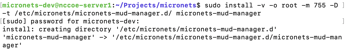
Open the management script to configure it for your implementation by entering the following command:
sudo vim /etc/micronets/micronets-mud-manager.d/micronets-mud-managerOnce the file is opened, modify the default variables in the management script to point to the server hosting our Micronets manager by changing the DEF_CONTROLLER_ADDRESS variable:
DEF_CONTROLLER_ADDRESS=nccoe-server1.micronets.net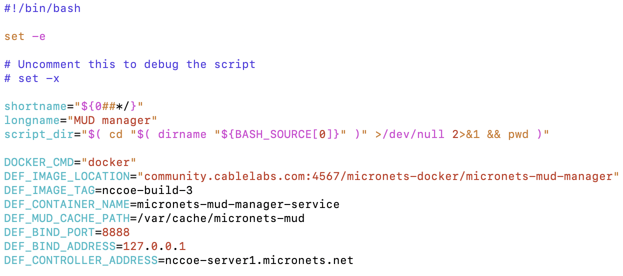
Download the docker image by entering the following command:
/etc/micronets/micronets-mud-manager.d/micronets-mud-manager docker-pullYou should see output similar to the following:
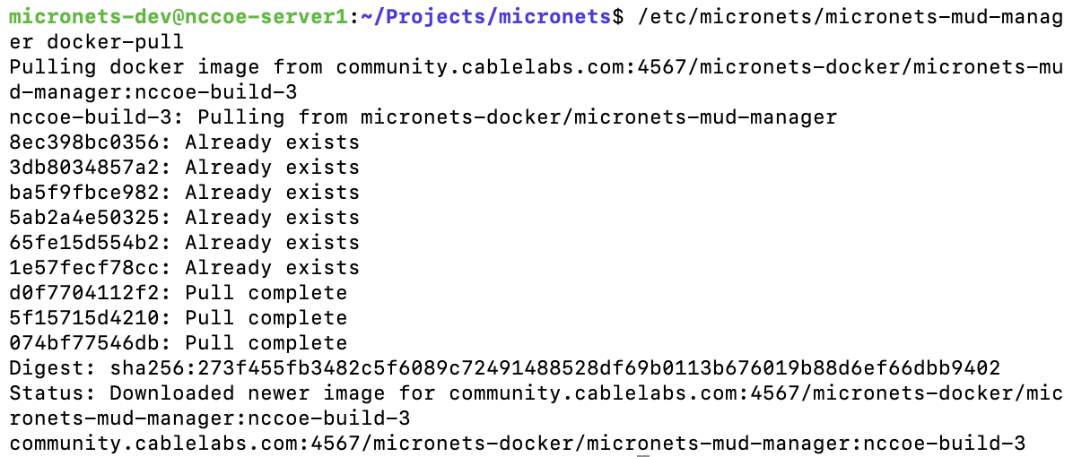
Next, set up the MUD cache directory by using the management script and entering the following command:
sudo /etc/micronets/micronets-mud-manager.d/micronets-mud-manager setup-cache-dirLast, start the MUD manager by entering the following command to run the docker container:
/etc/micronets/micronets-mud-manager.d/micronets-mud-manager docker-runYou should see output similar to the following:
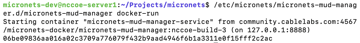
Verify that the MUD manager is running by using the following command and reviewing the logs:
/etc/micronets/micronets-mud-manager.d/micronets-mud-manager docker-logsYou should see output similar to the following:
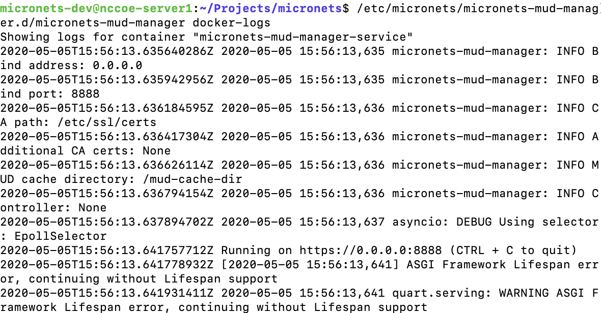
Set up a proxy pass to the MUD manager by adding the following entry to the NGINX server block:
Open the NGINX sites-available file for the server:
sudo vim /etc/nginx/sites-available/nccoe-server1.micronets.netAdd the following location to the server block:
location /micronets/mud-manager/ {

   proxy_pass http://localhost:8888/;

}
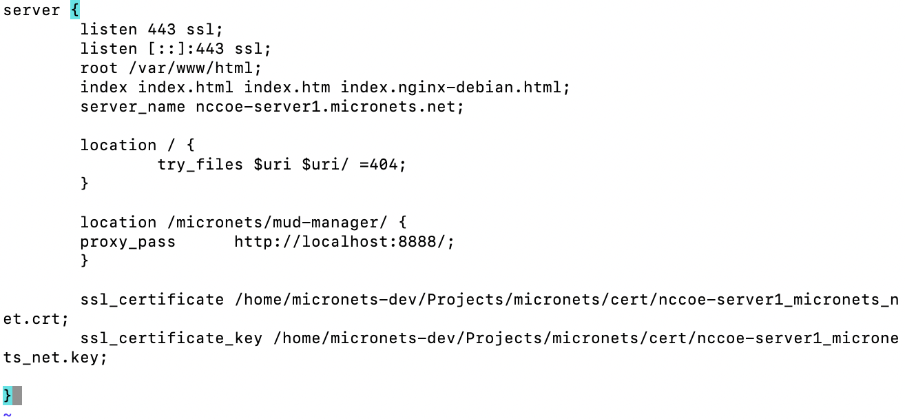
Reload the NGINX server by executing the following command:
sudo nginx -s reload
4.1.2.3.3 Operation
In this section, we test general operation of the MUD manager.
Test the MUD manager by retrieving a MUD file and using the following command (replace the MUD manager URL with the URL you created in Section 4.1.2.3.1):
curl -q -X POST -H "Content-Type: application/json" \
https://nccoe-server1.micronets.net/micronets/mud-manager/getMudFile \
-d '{"url": "https://alpineseniorcare.com/micronets-mud/ciscopi.json"}'
You should see the MUD file requested printed in the terminal:
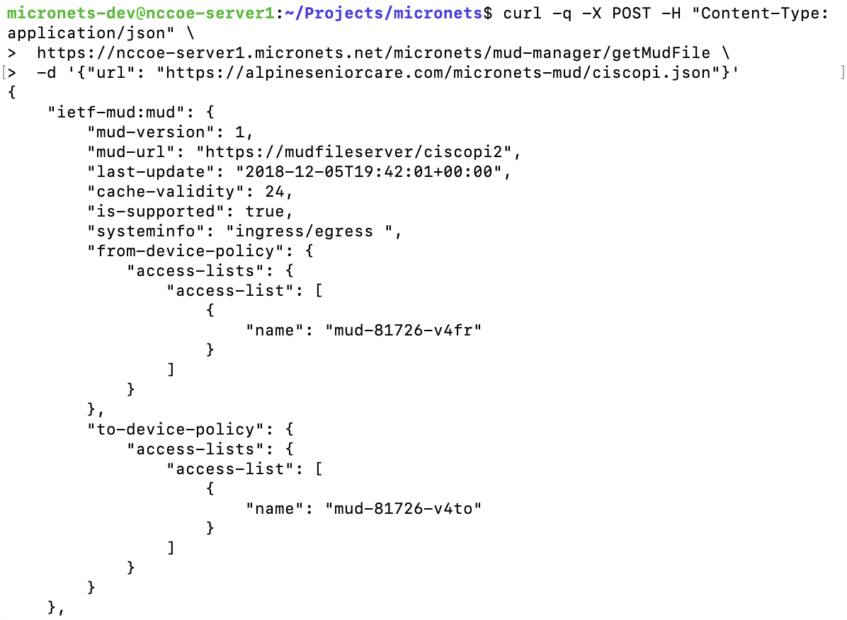
Check the MUD file cache directory to confirm that the MUD file requested is stored in the cache:
ls -1 /var/cache/micronets-mud/You should see the MUD file you just requested stored in the cache directory:
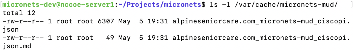
Now that the MUD manager has successfully retrieved its first MUD file, you can clear the cache by entering the following command:
/etc/micronets/micronets-mud-manager.d/micronets-mud-manager clear-cache-dirYou should see the following output once the command above has been executed:
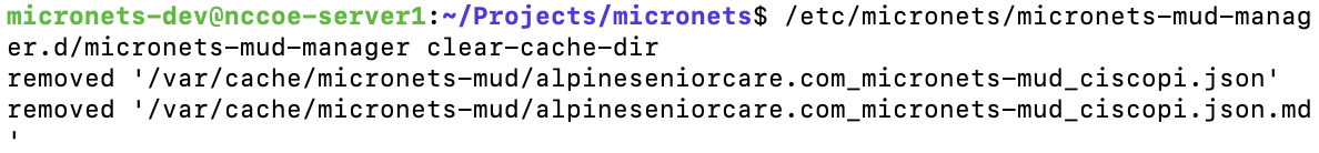
To output a list of additional docker commands supported by the management script, you can execute the following command:
/etc/micronets/micronets-mud-manager.d/micronets-mud-manager ––You should see output similar to the following:
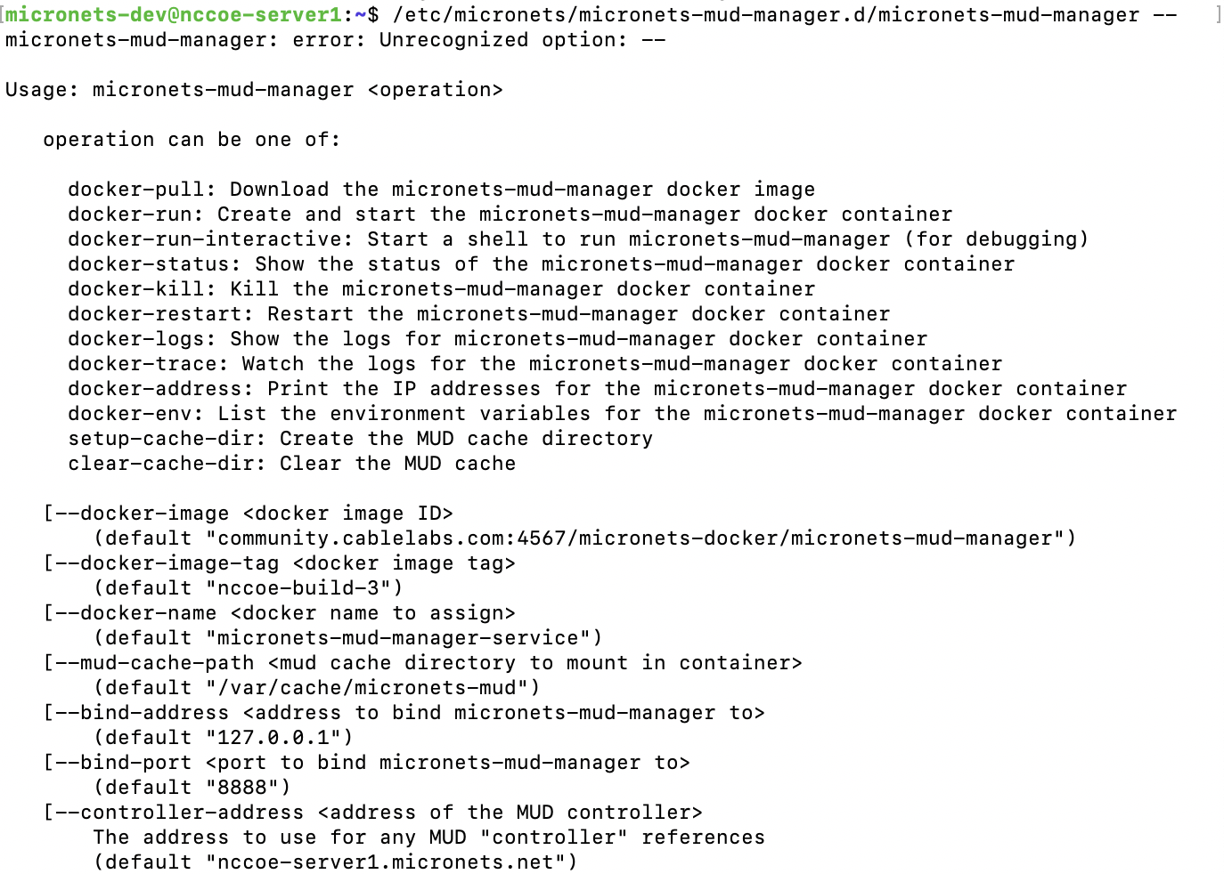
4.1.3 MUD File Server
This section describes the CableLabs MUD file server, which is a cloud-hosted service. The Build 3 implementation is designed a bit differently from the other three builds insofar as it requires a MUD registry to be incorporated in the solution as described in Volume B. We describe the MUD registry in this section of the documentation.
4.1.3.1 MUD File Server Overview
In the absence of a commercial MUD file server for use in this project, the NCCoE leveraged a Linode cloud-hosted Linux server to create the MUD file server that is accessible via the internet. This file server stores the MUD files along with their corresponding signature files for the IoT devices used in the project. Upon receiving a GET request for the MUD files and signatures, it serves the request to the MUD manager by using https.
4.1.3.2 Configuration Overview
The following subsections document the software and network configurations for the MUD file server.
4.1.3.2.1 Network Configuration
This server was hosted outside the lab environment on a Linode cloud-hosted Linux server. Its IP address was statically assigned.
4.1.3.2.2 Software Configuration
For this build, the server ran on an Ubuntu 18.04 LTS operating system. The MUD files and signatures were hosted by an NGINX web server and configured to use SSL/TLS encryption.
4.1.3.2.3 Hardware Configuration
The following hardware is required to install, configure, and operate the MUD file server:
4 GB of RAM
50 GB of free disk space
4.1.3.3 Setup
4.1.3.3.1 NGINX Web Server
Update your local package index by entering the following command:
sudo apt updateInstall NGINX by entering the following command:
sudo apt install nginxCreate the directory where the MUD files will be stored on the MUD file server as follows:
sudo mkdir -p /var/www/nccoe-server2.micronets.net/html/micronets-mud/Create an NGINX config file for this server. (Note: If you are following the architecture for this implementation, all Micronets cloud components will be hosted on this server, and this will be the same config file that will be modified to add routes to the different Micronets services.)
sudo vim /etc/nginx/sites-available/<ServerURL>
Below is an example of this command:
sudo vim /etc/nginx/sites-available/nccoe-server2.micronets.netAdd the following configuration block to the file. (Note: additional locations will be added to this configuration block as you continue to set up the different Micronets services.)
server {
    listen 443 ssl;
    listen [::]:443 ssl;
    root /var/www/nccoe-server2.micronets.net/html;
    index index.html index.htm index.nginx-debian.html;
    server_name nccoe-serve2.micronets.net;
    location / {
        # First attempt to serve request as file, then
        # as directory, then fall back to displaying a 404.
        try_files $uri $uri/ =404;
    }
    if ($scheme != "https") {
        return 301 https://$host$request_uri;
    }
    ssl_certificate /home/micronets-dev/Projects/micronets/cert/nccoe-server2_micronets_net.crt;
    ssl_certificate_key /home/micronets-dev/Projects/micronets/cert/nccoe-server2_micronets_net.key;
    include /etc/nginx/micronets-subscriber-forwards/*.conf;
}
Enable the file by creating a link from it to the sites-enabled directory, which NGINX reads from during startup:
sudo ln -s /etc/nginx/sites-available/nccoe-server2.micronets.net \
/etc/nginx/sites-enabled/nccoe-server2.micronets.net
Next, test to make sure that there are no syntax errors in any of your NGINX files:
sudo nginx -tYou should see output similar to the following:
If there are no problems, restart NGINX to enable your changes:
sudo systemctl restart nginx
4.1.3.3.2 MUD File Creation and Signing
To create MUD files for MUD-capable IoT devices, please follow the instructions in Build 1’s MUD File Serversection. Once MUD files and signature files are created, they can be stored in the web server directory created on the MUD file server in the previous section.
4.1.4 Micronets Gateway
This section describes the CableLabs Micronets Gateway, which, for this implementation, is an on-premises component. This implementation leveraged the nccoe-build-3 tagged version of CableLabs Micronets Gateway Git release. This documentation describes setting up your own Micronets gateway.
4.1.4.1 Micronets Gateway Overview
The Micronets Gateway establishes a connection to the Micronets Manager through the Websocket Proxy and receives traffic flow rules and other configuration information that it applies and enforces. Additionally, the Micronets Gateway supports wired and wireless connections, MUD-defined ACLs, and DPP onboarding.
4.1.4.2 Configuration Overview
The following subsections document the software and network configurations for the Micronets Gateway.
4.1.4.2.1 Network Configuration
Implementation of a Micronets gateway requires an internet source such as a digital subscriber line (DSL) or cable modem.
4.1.4.2.2 Software Configuration
The Micronets Gateway runs an Ubuntu 16.04 LTS server, which can support all the software dependencies and packages that will be installed during setup.
4.1.4.2.3 Hardware Configuration
For this implementation, we leveraged a Shuttle XPC slim DH170 with the following specs:
x86_64 processor (Intel or AMD)
at least two Ethernet ports
wireless adapter with a QUALCOMM Atheros AR9271 chipset
2 GB or higher of RAM
4.1.4.3 Setup
4.1.4.3.1 Install Dependencies
If Micronets is already installed and running, you should stop the services first by executing the following commands:
sudo systemctl stop micronets-gw.service

sudo systemctl stop micronets-hostapd.service
Update your local package index by entering the following command:
sudo apt-get updateYou should see the following output from this command:
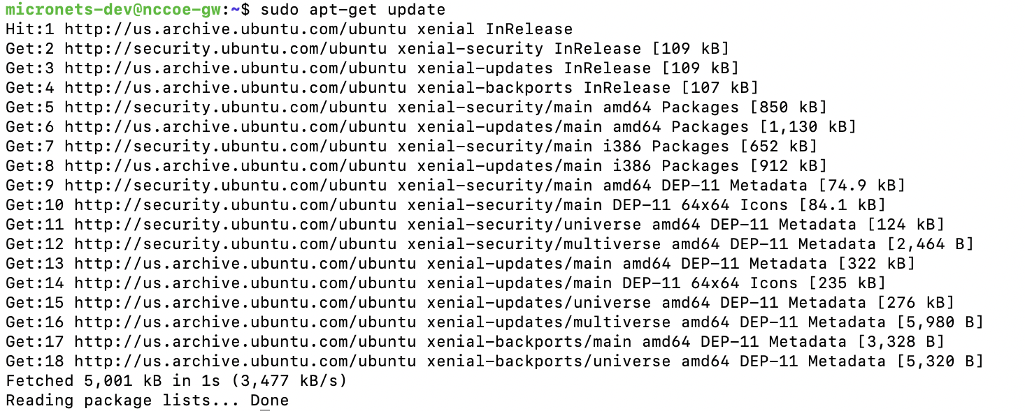
Install the python-pip, virtualenv, dnsmasq, python-six, and libnl-route-3-200 packages by executing the following command:
sudo apt-get -y install python-pip virtualenv dnsmasq python-six libnl-route-3-200If the packages are not already installed, you should see the following output from this command:
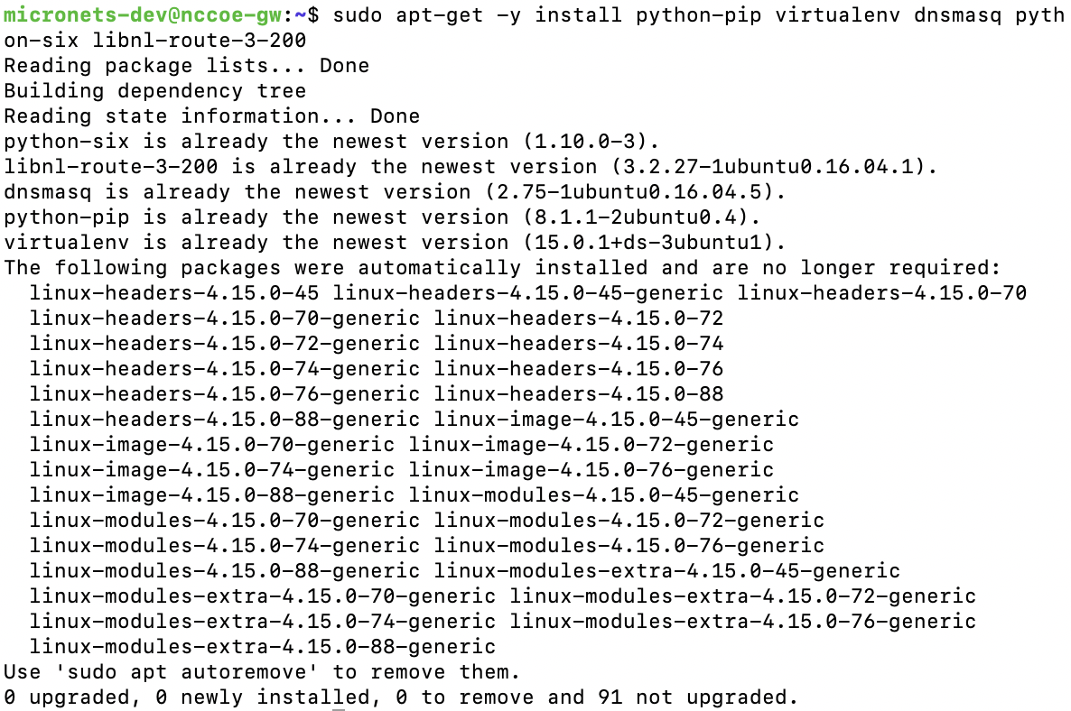
Install openvswitch version 2.9.2 and its dependencies from the CableLabs micronets-gw github repository by executing the following for loop:
for package in libopenvswitch_2.9.2-1_amd64.deb \

      openvswitch-common_2.9.2-1_amd64.deb \

      openvswitch-switch_2.9.2-1_amd64.deb ;

do curl -L -O https://github.com/cablelabs/micronets-gw/releases/download/1.0.55/${package};

sudo dpkg -i ${package};

done
You should see the following output from this command:
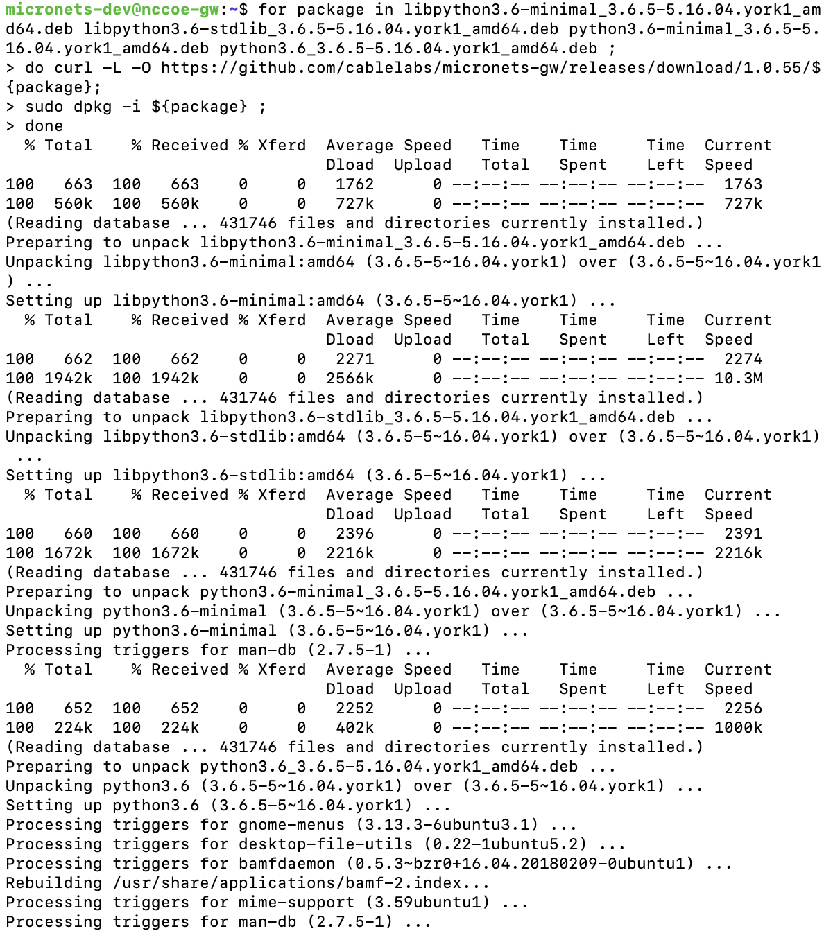
Install Python version 3.6 and its dependencies from the CableLabs micronets-gw github repository by executing the following for loop:
for package in libpython3.6-minimal_3.6.5-5.16.04.york1_amd64.deb \

      libpython3.6-stdlib_3.6.5-5.16.04.york1_amd64.deb \

      python3.6-minimal_3.6.5-5.16.04.york1_amd64.deb \

      python3.6_3.6.5-5.16.04.york1_amd64.deb ;

do curl -L -O https://github.com/cablelabs/micronets-gw/releases/download/1.0.55/${package};
You should see the following output from this command:
4.1.4.3.2 Install Micronets Packages
Enter the following command to download the Micronets hostapd package:
curl -L -O https://github.com/cablelabs/micronets-gw/releases/download/1.0.55/micronets-hostapd-1.0.21.deb
You should see output similar to the following:
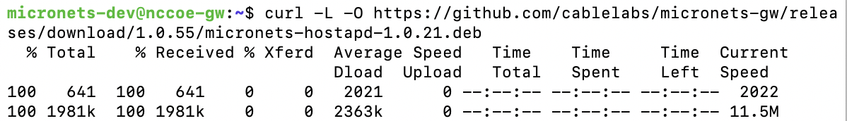
Enter the following command to de-package the Micronets hostapd package:
sudo dpkg -i micronets-hostapd-1.0.21.debYou should see output similar to the following:
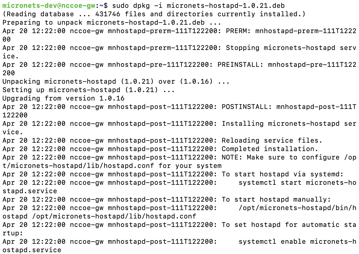
Enter the following command to download the Micronets Gateway package:
curl -L -O https://github.com/cablelabs/micronets-gw/releases/download/1.0.55/micronets-gw-1.0.55.deb
You should see output similar to the following:
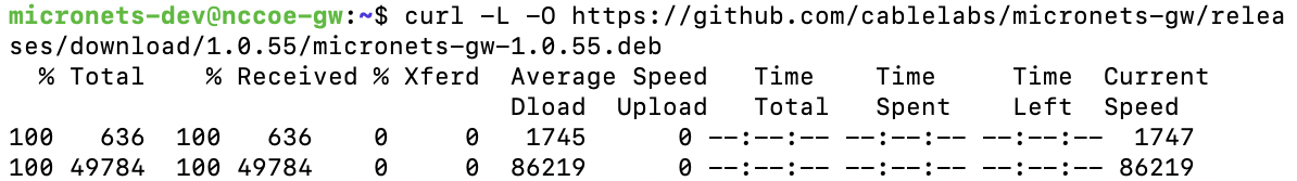
Enter the following command to install the Micronets hostapd package:
sudo dpkg -i micronets-gw-1.0.55.debAfter a bit of a delay, you should see output similar to the following:

Enable autostart for the Micronets hostapd service by entering the following command:
sudo systemctl enable micronets-hostapd.serviceEnable autostart for the Micronets Gateway Service by entering the following command:
sudo systemctl enable micronets-gw.serviceStart the Micronets hostapd service by entering the following command:
sudo systemctl start micronets-hostapd.serviceStart the Micronets Gateway Service by entering the following command:
sudo systemctl start micronets-gw.serviceVerify that the gateway service started successfully by running the following command:
sudo systemctl status micronets-gw.serviceVerify that the Micronets hostapd service started successfully by running the following command:
sudo systemctl status micronets-hostapd.service
CableLabs documentation notes that installing the micronets-gw package should produce the following results:
installation of the Micronets Gateway Service in the /opt/micronets-gw directory
installation of the ifup/down and dnsmasq extension scripts for configuration of openvswitch and the micronets-gw service via /etc/network/interfaces
installation of a sample/etc/network/interfaces file in /opt/micronets-gw/doc/interfaces.sample
installation and start of the micronets-gw-service systemd service
4.1.5 IoT Devices
This section provides configuration details for the Linux-based IoT development kits used in the build, which can be onboarded via DPP. It also provides information regarding a basic IoT application used to test the MUD process.
4.1.5.1 IoT Devices Overview
Build 3, like the other builds in this project, leverages the Raspberry Pi devkit with capabilities developed to make these devices both MUD- and DPP-capable. The Raspberry Pi runs the Raspbian 9 OS and is provisioned with one bootstrapping public/private key pair during device setup. The Micronets Proto-Pi software developed by CableLabs in combination with the added hardware outlined in the configuration section adds DPP capability to these devices. There are two onboarding mechanisms called modes supported by the Micronets Proto-Pi software: DPP mode and clinic mode. The clinic mode provides an onboarding mechanism via automated installation of Wi-Fi security certificates, and the DPP mode provides QR code–based device onboarding. For this implementation, we only describe setting up and leveraging the Micronets Proto-Pi software in DPP mode. If you would like to leverage the clinic mode of this software, follow the documentation provided by CableLabs: https://github.com/cablelabs/micronets-pi3/blob/nccoe-build-3/README.md#Installation.
4.1.5.2 Configuration Overview
The following subsections document the software and network configurations for the Micronets Proto-Pi device.
4.1.5.2.1 Network Configuration
The following network configurations are required to install, configure, and operate the Micronets Proto-Pi device:
wired network connection to a separate access point that provides both initial internet access to self-register the device and remote management access to the device during setup
4.1.5.2.2 Software Configuration
The following software is required to install, configure, and operate the Micronets Proto-Pi device:
tool for flashing images to Secure Digital (SD) card (This implementation leveraged balenaEtcher: https://www.balena.io/etcher/.)
latest Raspbian image from:
CableLabs at the following link (this image has Secure Shell (SSH) and Visual (vi) preinstalled): https://www.dropbox.com/s/37ygauo02ltxirf/raspbian-buster-ssh-updates.zip?dl=0
Or you can download the latest Buster distribution and install packages yourself from the following link: https://www.raspberrypi.org/software/operating-systems/
4.1.5.2.3 Hardware Configuration
The following hardware is required to install, configure, and operate the Micronets Proto-Pi device:
Raspberry Pi (version 3B+)
SD card
Alfa adapter
Ethernet cable
4.1.5.3 Setup
4.1.5.3.1 Install Dependencies
Connect the SD card to your computer.
Open balenaEtcher (or whatever tool you have downloaded for flashing SD cards).
Click Select image, and select the Raspbian image you downloaded:
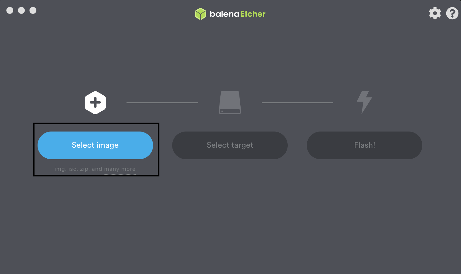
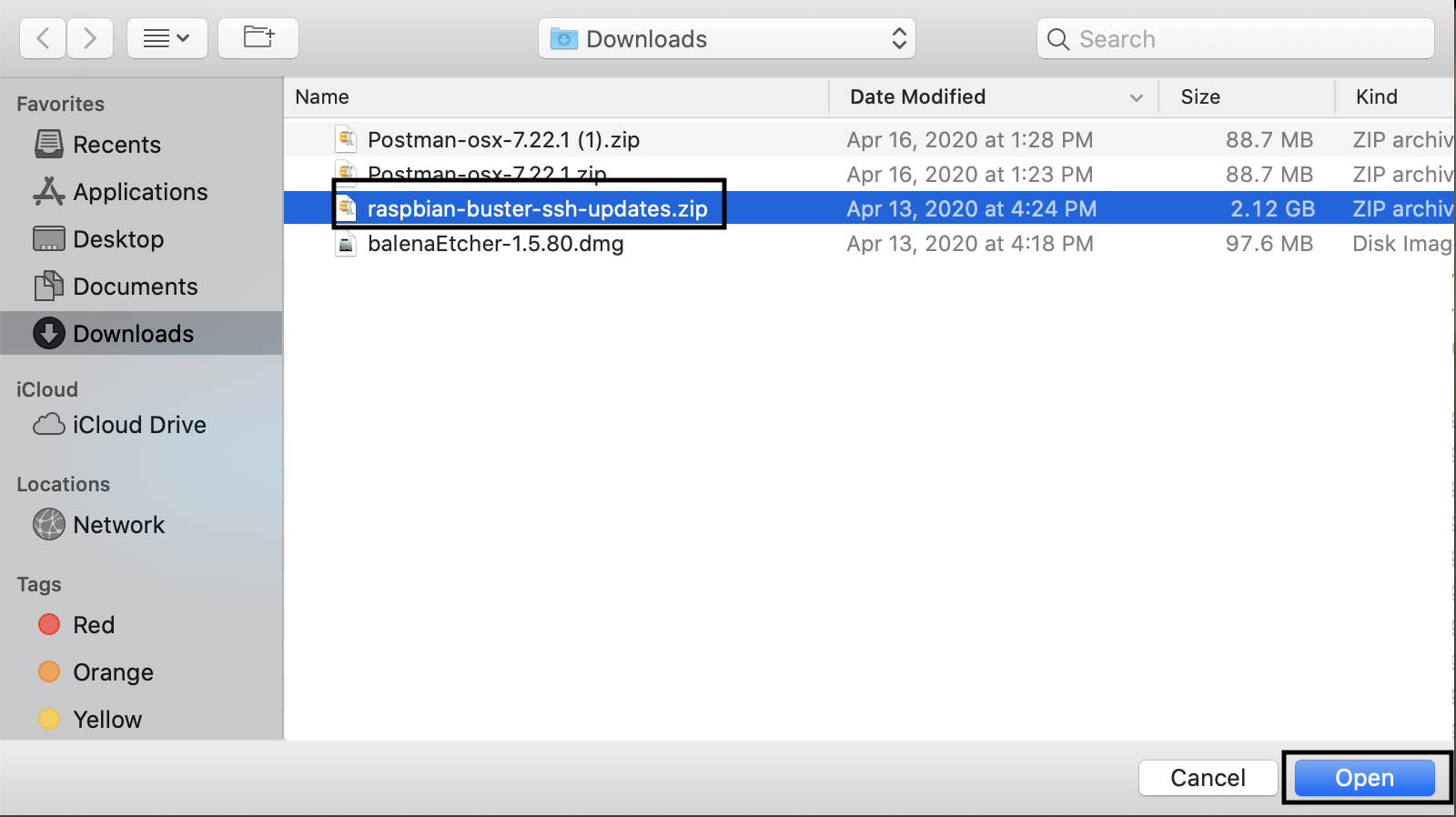
Click Select target, and select the SD card you connected to the computer (the software may automatically recognize the target):
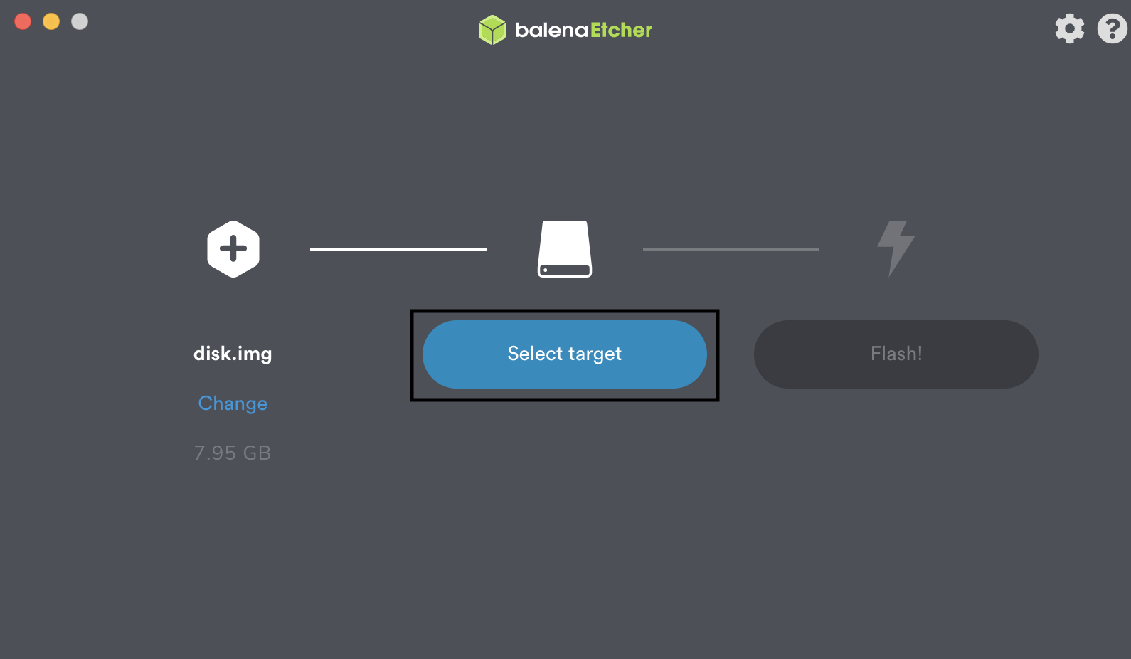
You should see something similar to the following:
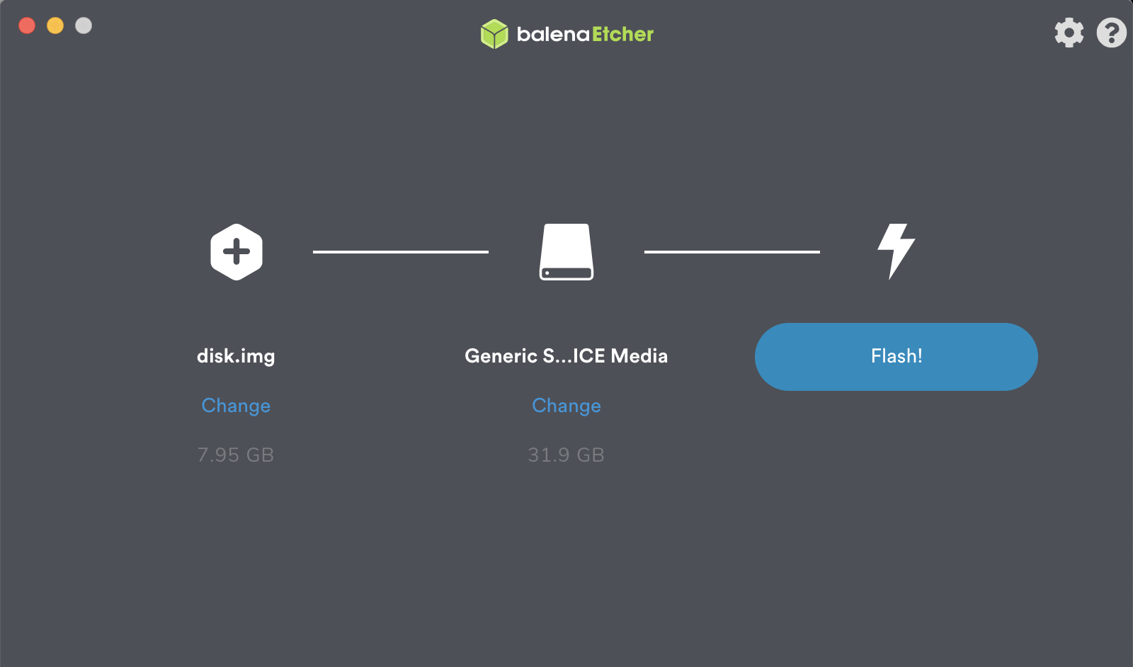
Click Flash! to start the flashing process:
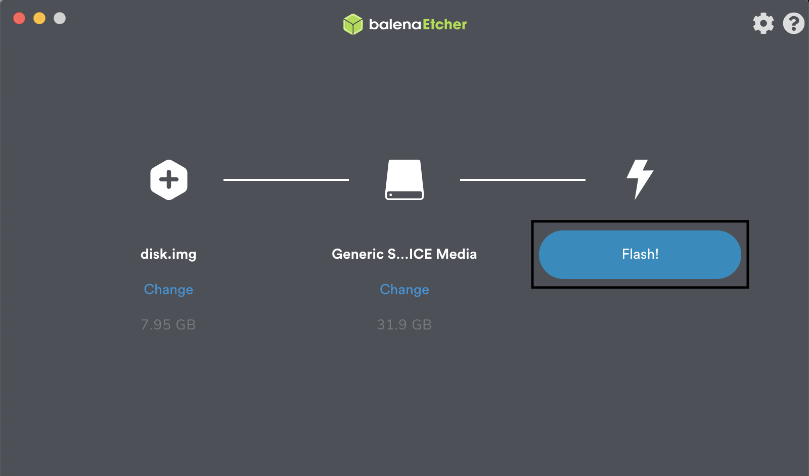
You may be prompted to enter your password, as seen below:
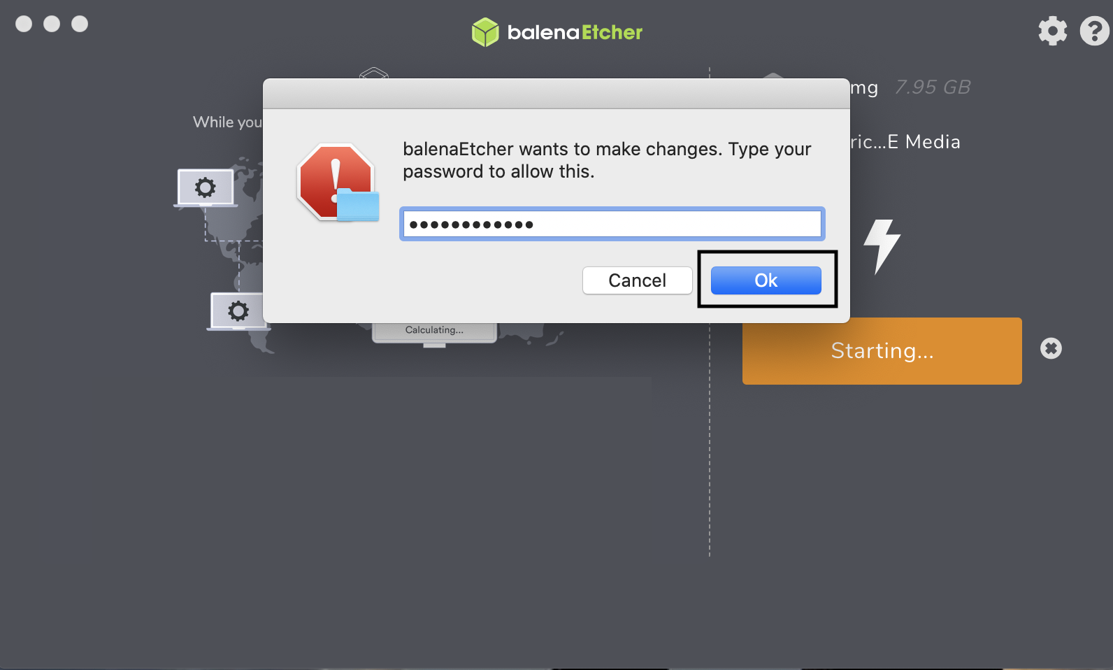
When the flashing has completed, you should see output similar to the following:
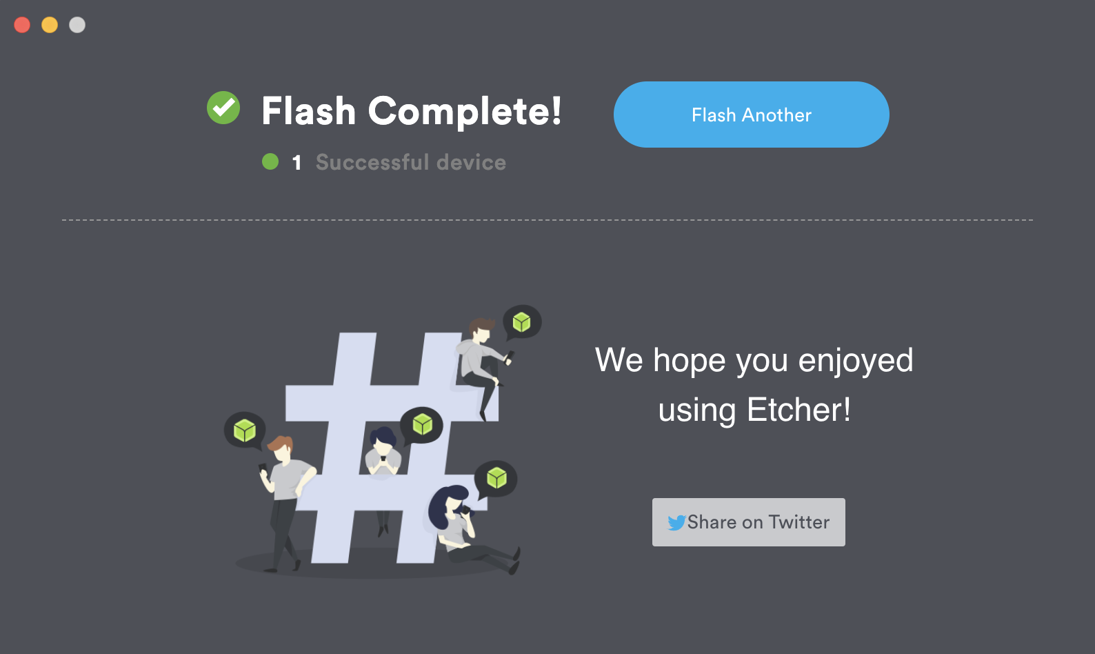
4.1.5.3.2 Install Micronets Proto-Pi
Insert the SD card to the Raspberry Pi, and connect power using a micro–Universal Serial Bus (USB) cable.
Connect to the Raspberry Pi from a remote machine by using SSH:
Note: You will need to figure out the Ethernet IP address of the Raspberry Pi, which can be done by looking at the DHCP assignments on the gateway to which you connected the Raspberry Pi.
Enter the following command once you have identified the device’s IP address:
ssh pi@[ipaddress]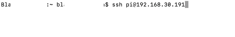
You will be prompted to continue connecting, as this is the first time connecting to the device:
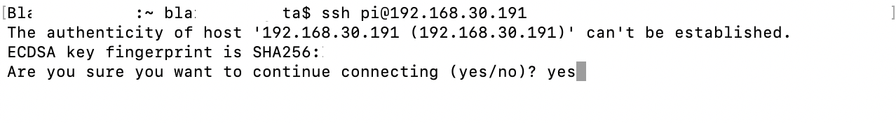
Enter the password for the Raspberry Pi:
Note: The password is “micronets” if you are leveraging the CableLabs Raspberry Pi image:
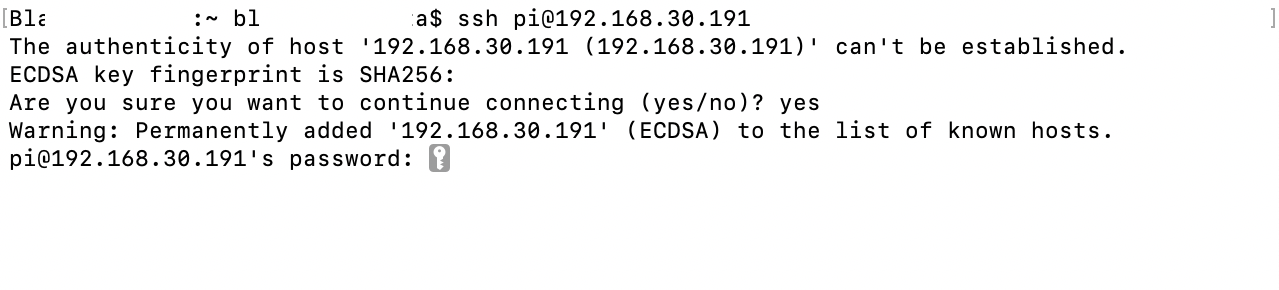
You will now have access to a terminal on the Raspberry Pi:
![This image shows the expected result after the command "ssh pi@[ipaddress]" has been used to connect to the Raspberry Pi.](../_images/image147.png)
Ensure that you are in the home directory by entering the following command:
cd ~Download the Micronets Proto-Pi software from GitHub by entering the following command:
git clone https://git@github.com/cablelabs/micronets-pi3.gitYou should see output similar to the following:
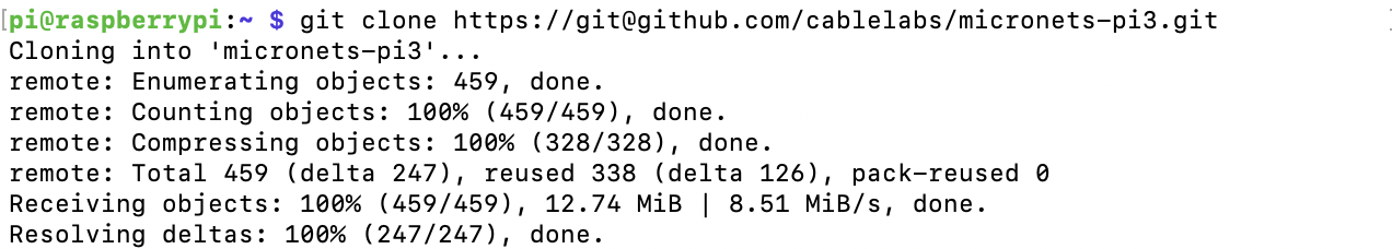
Change into the micronets-pi3 directory by entering the following command:
cd micronets-pi3/Check out the nccoe-build-3 branch by entering the following branch:
git checkout nccoe-build-3You should see output similar to the following:

Change into the deploy directory by entering the following command:
cd deploy/Install the Micronets Proto-Pi software by entering the following command:
./installWhen prompted to accept disk space required, input Y as seen below:
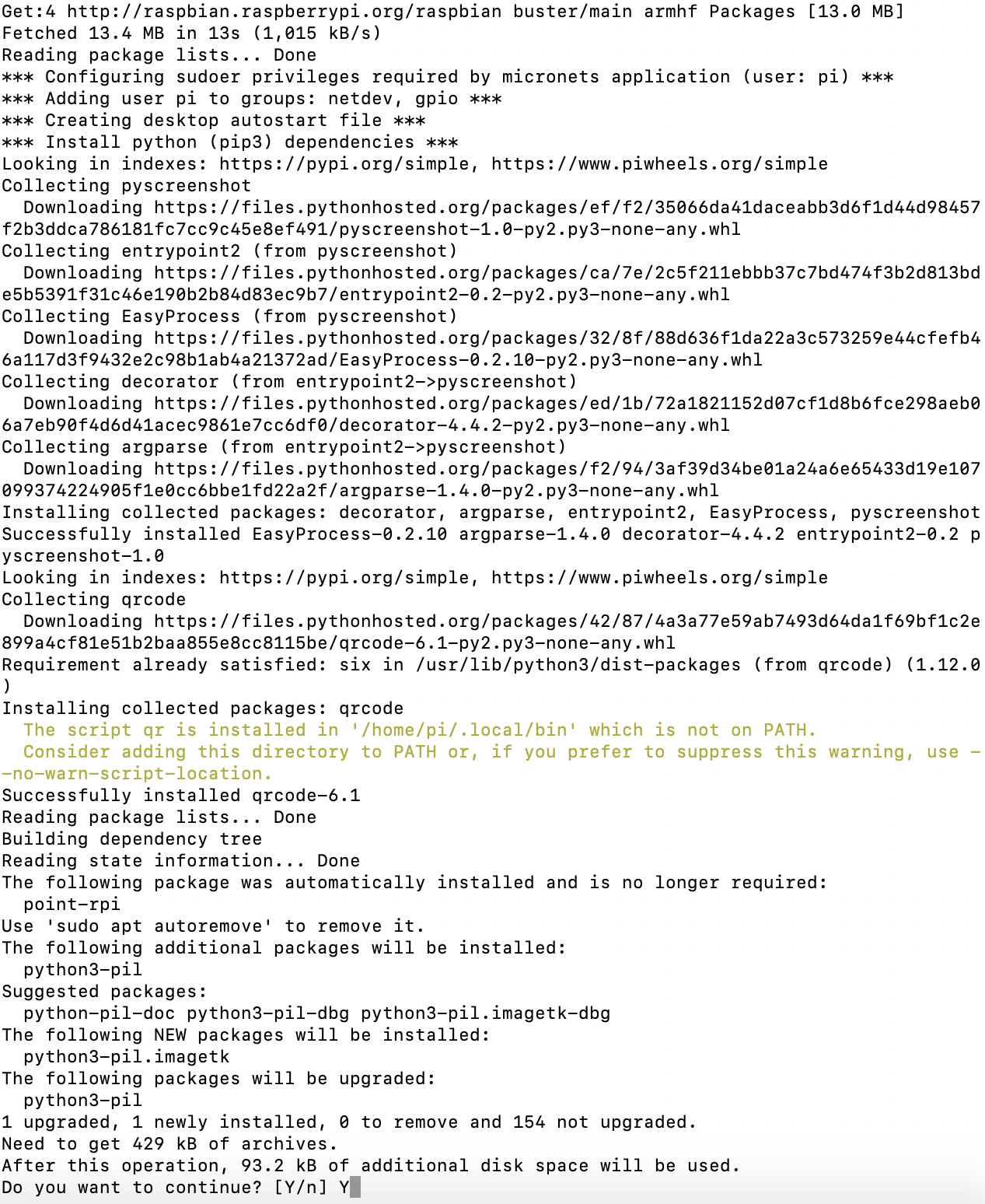
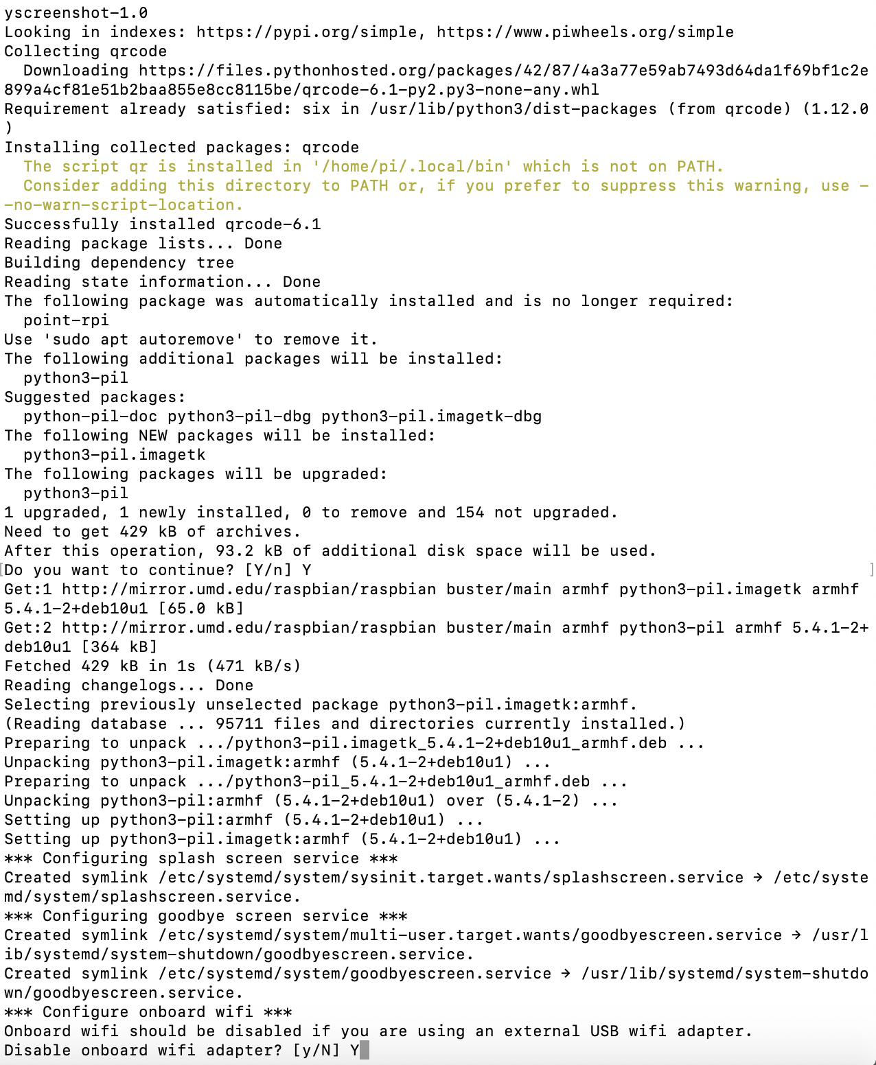
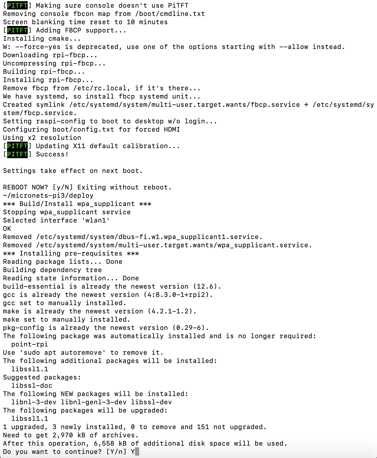
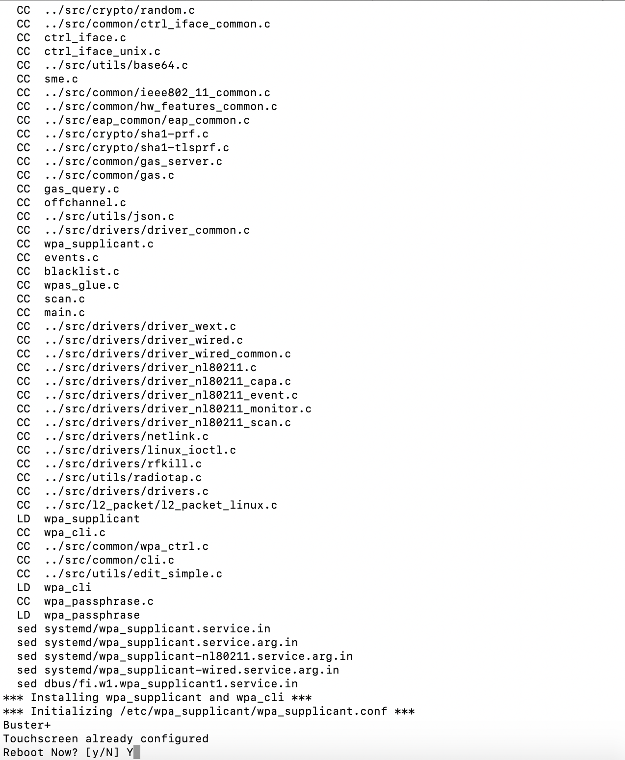
4.1.5.3.3 Operation
Four buttons are used for general operation in the Micronets Proto-Pi application. These buttons are on the right side of the application and will be described in the upcoming sections.
Accessing Raspberry Pi Using Virtual Network Computing (VNC )Viewer:
Access the Raspberry Pi using the VNC Viewer, enter the IP address of the Raspberry Pi, and click Connect:
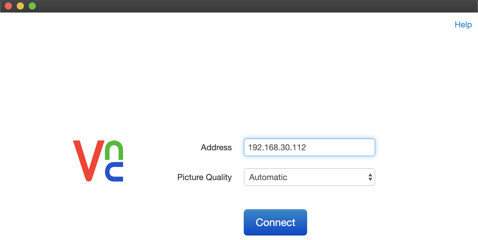
You will be prompted to accept and store the signature for this device as it is the first time connecting to it. Click OK:
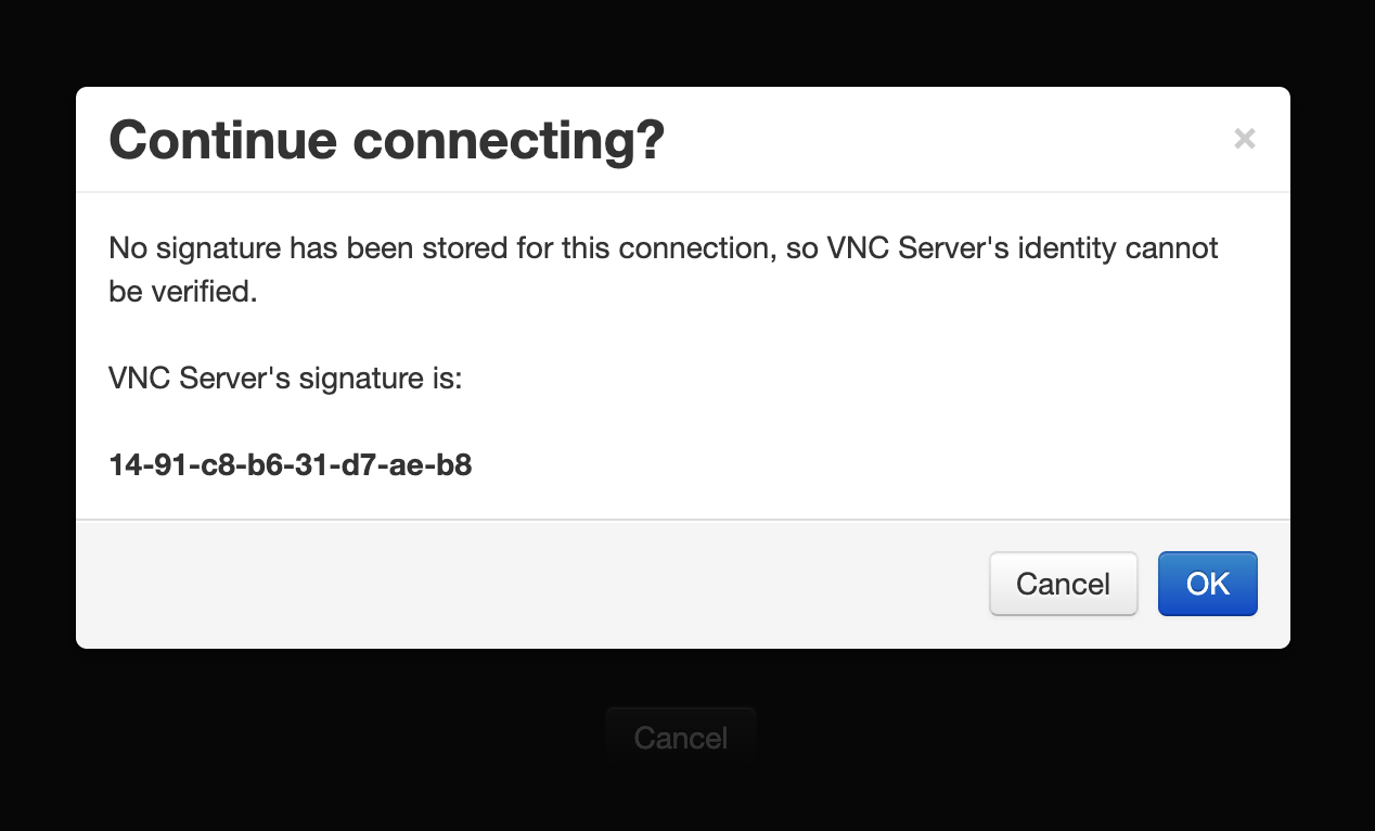
Once accepted, proceed to log in with the username and password, as seen below:
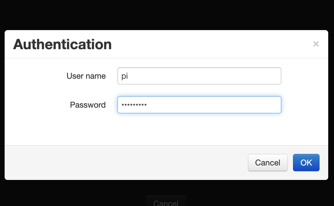
You should see the Micronets Proto-Pi application on the screen as seen below:
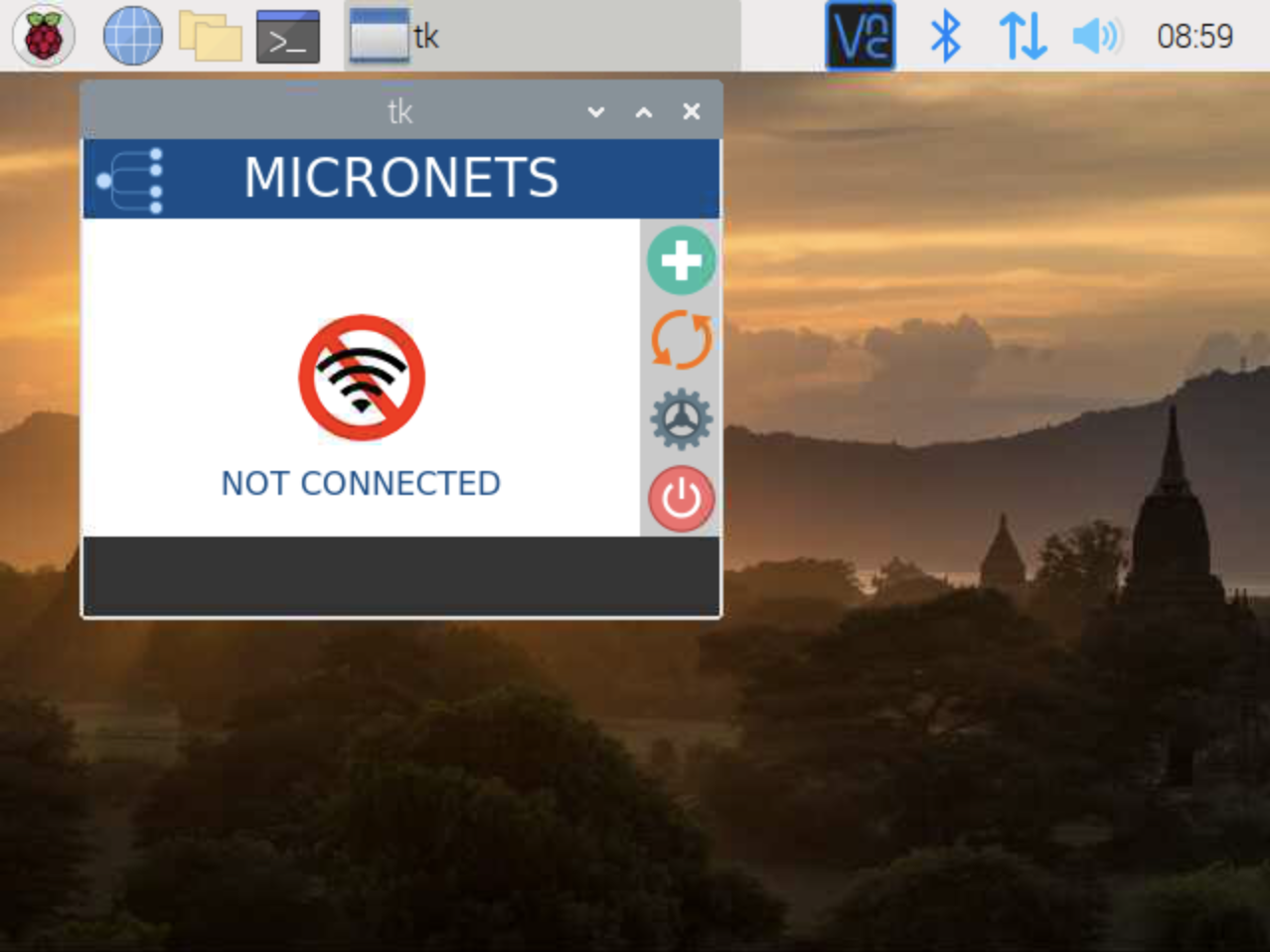
The onboard button described in the following steps allows the user to initiate the onboard operation:
Click the green button to initiate the onboard process:
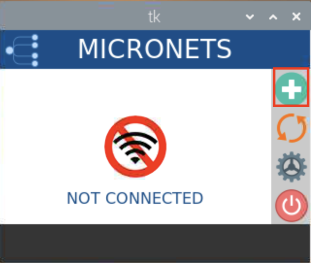
A QR code will appear as seen below. The mobile application will be used to scan this QR code for onboarding:
The cycle button described in the following steps turns the Wi-Fi off/on to reconnect to the configured service set identifier (SSID).
Click the orange cycle button:
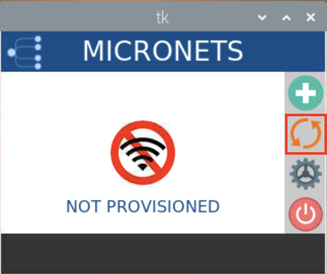
You should see output similar to the following:
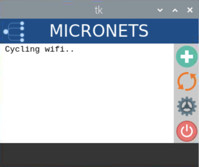
The settings button described in the following steps will open the settings menu, which has four different operations/buttons:
Click the gear button:
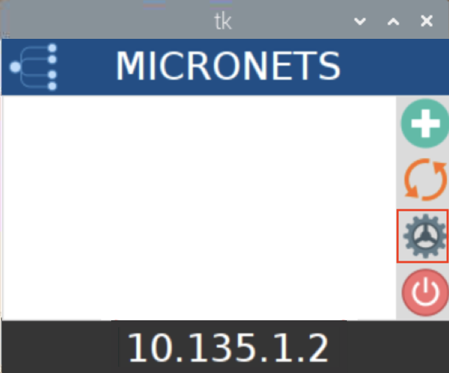
The following menu will appear:
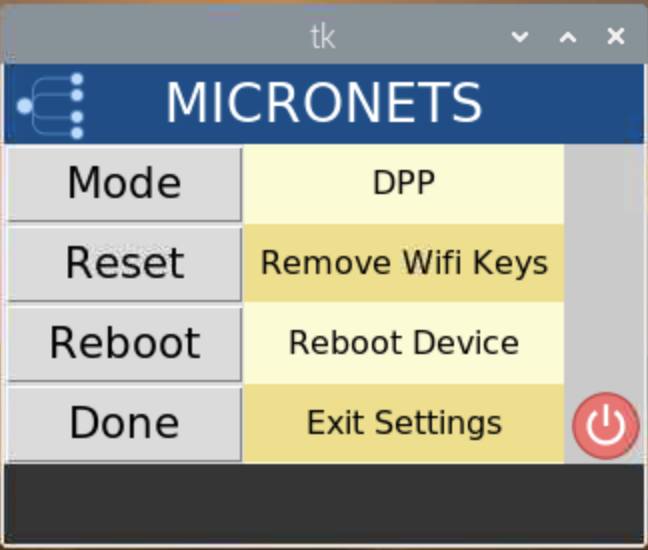
Click the Mode button to change the onboarding mode from DPP to clinic, and vice versa:
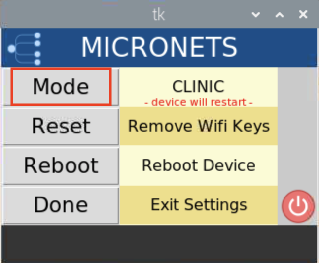
The following screen displays:
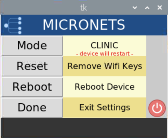
Click the Mode button again to return to DPP mode:
You will see the following change to your screen:
Click the Reset button to clear Wi-Fi credentials. (Note: If the device is in clinic mode, it will restore the credentials for the clinic Wi-Fi.)
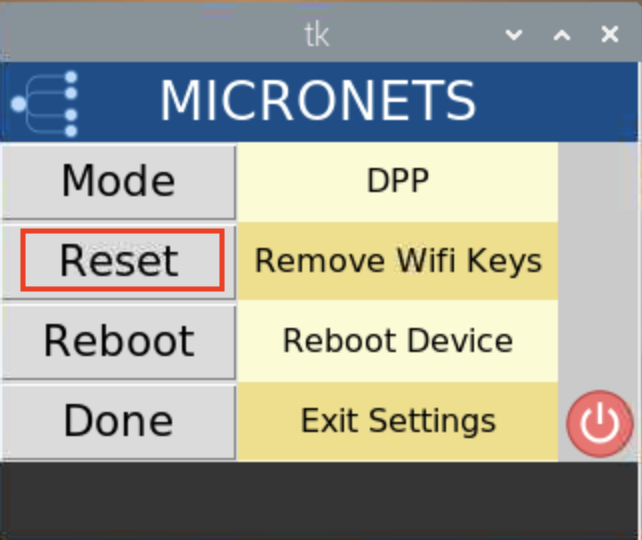
You should see output similar to the following:
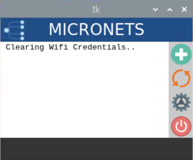
Click the Reboot button to reboot the Pi:
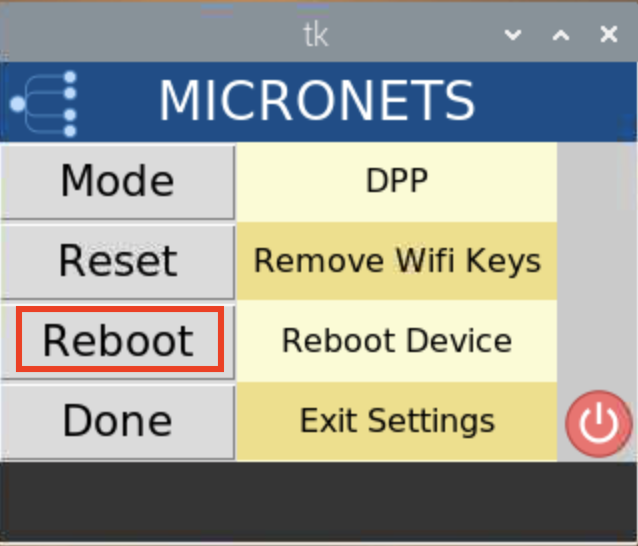
You should see output similar to the following:
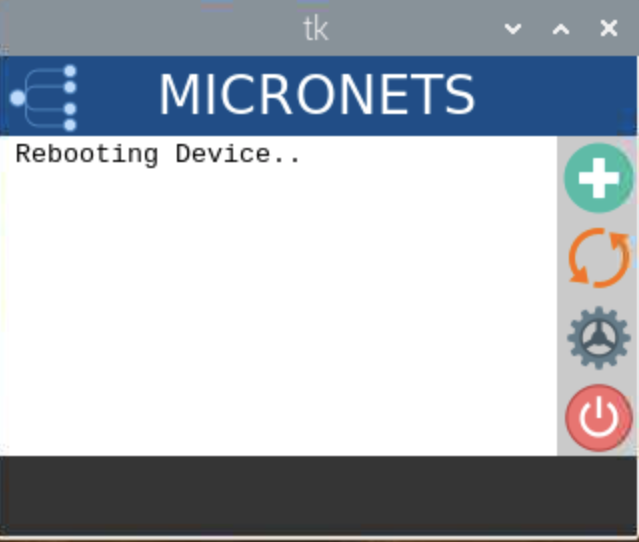
Click the Done button to exit the settings screen:
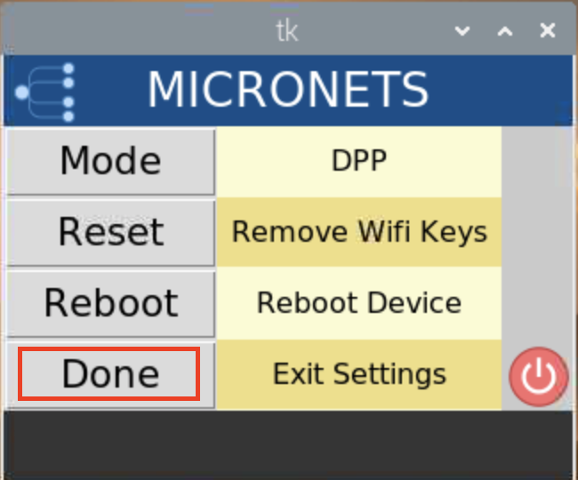
You should see output similar to the following:
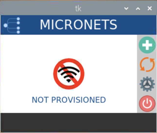
The power button described in the following steps appears on the main screen of the Micronets Proto-Pi application and is used to restart the application as well as shut down the Pi entirely:
Tap the power button to restart the application:
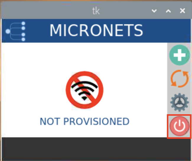
You should see output similar to the following:

Next, the following screen should appear:
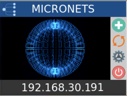
Finally, the main screen appears as seen below:
Hold the power button to shut down the Pi:
You should see output similar to the following:
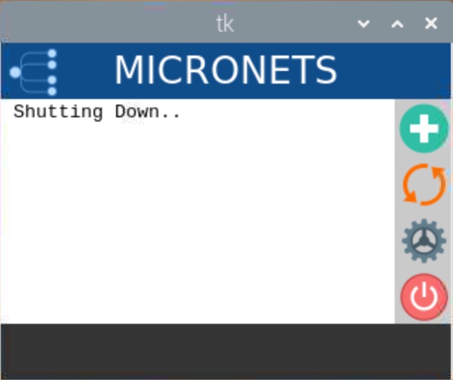
4.1.6 Update Server
Build 3 leverages the preexisting update server that is described in Build 1’s Update Server section. To implement a server that will act as an update server, see the documentation in Build 1’s Update Server section. The update server will attempt to access and be accessed by the IoT device, which, in this case, is one of the development kits we built in the lab.
4.1.7 Unapproved Server
Build 3 leverages the preexisting unapproved server that is described in Build 1’s Unapproved Server section. To implement a server that will act as an unapproved server, see the documentation in Build 1’s Unapproved Server section. The unapproved server will attempt to access and be accessed by an IoT device, which, in this case, is one of the MUD-capable devices on the implementation network.
4.1.8 CableLabs MUD Registry
This section describes the CableLabs MUD registry, which, for this implementation, is a cloud-provided service. This implementation leveraged the nccoe-build-3 branch of CableLabs MUD registry Git release. This service can be hosted by the implementer or another party. This documentation describes setting up your own MUD registry.
4.1.8.1 CableLabs MUD Registry Overview
The Micronets MUD registry provides the capability to look up the MUD URL that is associated with a particular device. This registration and MUD URL association can be done manually or by the device using self-registration.
4.1.8.2 Configuration Overview
The following subsections document the software and network configurations for the MUD registry. Please note that the MUD manager, Micronets Manager, Websocket Proxy, MUD registry, and MSO portal are all implemented on the same server, nccoe-server1.micronets.net. Many of these configurations have already been covered in previous sections of this document but are repeated here for consistency.
4.1.8.2.1 Network Configuration
This server was hosted outside the lab environment on a Linode cloud-hosted Linux server. Its IP address was statically assigned.
4.1.8.2.2 Software Configuration
For this build, the server ran on an Ubuntu 18.04 LTS operating system. The MUD registry runs in its own docker container and is configured to use SSL/TLS encryption.
The following software is required to install, configure, and operate the MUD registry:
an Ubuntu 18.04 LTS server reachable by the server hosting the Micronets Manager instances and any Micronets gateways
docker (v18.06 or higher)
curl
NGINX
4.1.8.2.3 Hardware Configuration
The following hardware is required to install, configure, and operate the MUD registry:
4 GB of RAM
50 GB of free disk space
4.1.8.3 Setup
4.1.8.3.1 Install and Configure MUD Registry
Log in to docker by using the following command:
docker loginYou should see output similar to the following:
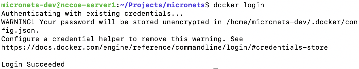
Retrieve the nccoe-build-3 tagged image by entering the following command:
docker pull community.cablelabs.com:4567/micronets-docker/micronets-mud-registry:nccoe-build-3
Execute the following command to run the image that was just retrieved:
The command will follow the syntax below. Replace <MUDFILESERVER_URL> with your MUD file server URL:
docker run -d -p 127.0.0.1:3082:3082 –env mud_base_uri=https:// <MUDFILESERVER_URL> -v /etc/micronets/micronets-mud-registry.d/:/etc/micronets/config–name=micronets-mud-registry community.cablelabs.com:4567/micronets-docker/micronets-mud-registry:nccoe-build-3
docker run -d -p 127.0.0.1:3082:3082 --env mud_base_uri=https://nccoe-server2.micronets.net/micronets-mud -v
/etc/micronets/micronets-mud-registry.d/:/etc/micronets/config --name=micronets-mud-registry
community.cablelabs.com:4567/micronets-docker/micronets-mud-registry:nccoe-build-3
Configure your own vendor code for your implementation by completing the following steps:
Create and modify the mud-registry.conf file by executing the following command. (Note: The configuration file must be named “mud-registry.conf” and must reside in a host folder that is passed to the docker instance in the docker run command executed in the previous step.)
sudo vim /etc/micronets/micronets-mud-registry.d/mud-registry.confReplace <VENDOR-CODE> with your choice of vendor name, <MUDREGISTRY_URL> with the MUD registry URL, and <MUDFILESERVER_URL> with the MUD file server URL:
{“vendors” : {“<VENDOR-CODE> “: “https:// <MUDREGISTRY_URL> /registry/devices”, “ABCD”: “https://abcd-domain.com:3082/vendors”}, “mud_base_uri”: “https:// <MUDFILESERVER_URL> /micronets-mud”, “device_db_file”: “/etc/micronets/config/device-registration.nedb”}For this implementation, we added the following:
{
   "vendors" : {
      "TEST": "https://nccoe-server1.micronets.net/registry/devices",
     "ABCD": "https://abcd-domain.com:3082/vendors"
   },
   "mud_base_uri": "https://nccoe-server2.micronets.net/micronets-mud",
   "device_db_file": "/etc/micronets/config/device-registration.nedb"
}
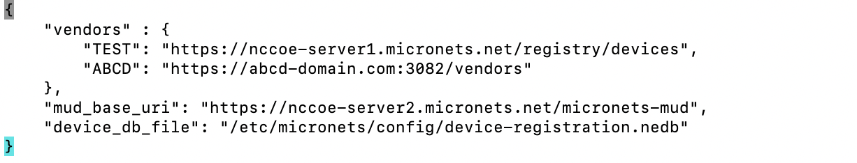
Modify the sites-available file for the NGINX server to route appropriate traffic to the docker container by executing the following commands:
Open the sites-available file for the NGINX server by entering the following command:
sudo vim /etc/nginx/sites-available/nccoe-server1.micronets.netMap the location for the /registry/devices so it is routed to vendors/ in the docker instance running on port 3082 and for the /mud/ to be passed to the global registry by adding the following to the server block:
location /registry/devices {
    proxy_pass http://localhost:3082/vendors/;
}
location /mud/{
    proxy_pass http://localhost:3082/registry/;
}
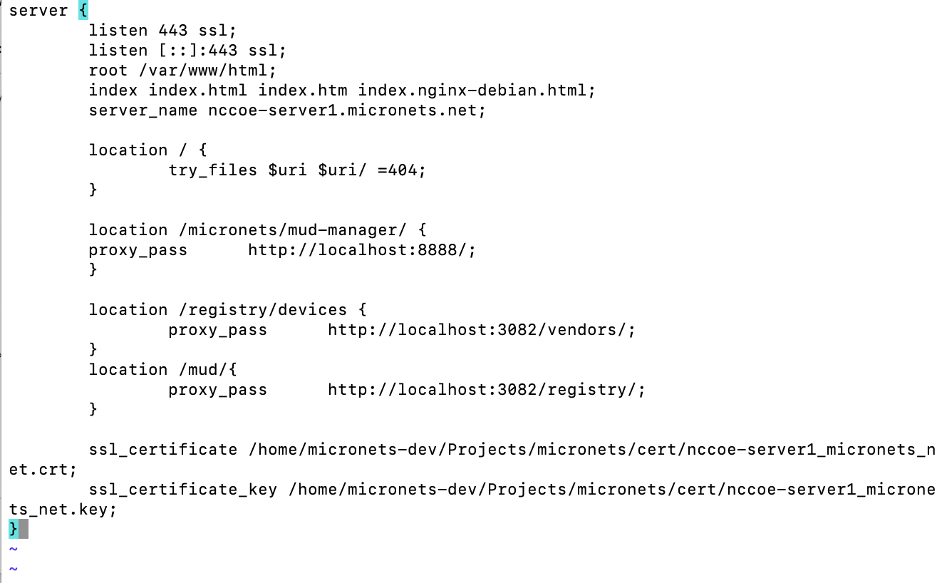
4.1.9 CableLabs Micronets Manager for SDN Control
This section describes the CableLabs Micronets Manager, which, for this implementation, is a cloud-provided service. This implementation leveraged the nccoe-build-3 branch of CableLabs Micronets Manager Git release. This service can be hosted by the implementer or another party. This documentation describes setting up your own Micronets Manager.
4.1.9.1 CableLabs Micronets Manager Overview
The Micronets Manager provides micro-services to the implementation. It receives onboarding requests, bootstrapping information, and more for a particular subscriber and is a core component for handing off requests among different components in the architecture.
4.1.9.2 Configuration Overview
The following subsections document the software and network configurations for the Micronets Manager. Please note that these instructions have the MUD manager, Micronets Manager, Websocket Proxy, MUD registry, and MSO portal all deployed onto the same server, nccoe-server1.micronets.net. Many of these configurations are already covered in previous sections of this document but are repeated here for consistency.
4.1.9.2.1 Network Configuration
This server was hosted outside the lab environment on a Linode cloud-hosted Linux server. Its IP address was statically assigned.
4.1.9.2.2 Software Configuration
For this build, the server ran on an Ubuntu 18.04 LTS operating system. The Micronets Manager runs in its own docker container and is configured to use SSL/TLS encryption.
The following software is required to install, configure, and operate the Micronets Manager:
an Ubuntu 18.04 LTS server reachable by any Micronets gateways
docker (v18.06 or higher)
docker-compose (v1.23.1 or higher)
OpenSSL (1.0.2g or higher)
curl
NGINX (1.14.0 or higher)
4.1.9.2.3 Hardware Configuration
The following hardware is required to install, configure, and operate the Micronets Manager:
4 GB of RAM
50 GB of free disk space
4.1.9.3 Setup
4.1.9.3.1 Install Dependencies
Install docker, docker-compose, openssl, curl, and NGINX by entering the following command:
sudo apt-get install docker docker-compose openssl curl nginx
4.1.9.3.2 Install and Configure the Micronets Manager
Ensure the version of docker-compose is correct and upgrade if needed:
Check the current version by entering the following command:
docker-compose ––versionYou should see the version output as seen below:

If the version is earlier than v1.23.1, run the following command to install a new version in /usr/local/bin directory:
Download the docker-compose utility:
curl -s -L -O https://github.com/docker/compose/releases/download/1.24.1/docker-compose-Linux-`uname -m\`
Install the docker-compose utility to the appropriate directory:
sudo install -v -o root -m 755 docker-compose-Linux-`uname -m\` /usr/local/bin/docker-compose
You should see output similar to the following:
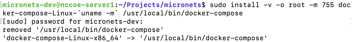
Download the Micronets Manager management script, and install it by entering the following commands:
Download the Micronets Manager management script:
curl -s -O https://raw.githubusercontent.com/cablelabs/micronets-manager/nccoe-build-3/scripts/mm-container
Download the docker-compose utility:
curl -s -O https://raw.githubusercontent.com/cablelabs/micronets-manager/nccoe-build-3/scripts/docker-compose.yml
Install the management script to the appropriate location:
sudo install -v -o root -m 755 -D -t /etc/micronets/micronets-manager.d mm-container
You should see output similar to the following:
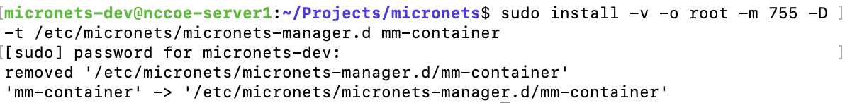
Install the docker-compose utility to the appropriate location:
sudo install -v -o root -m 644 -D -t /etc/micronets/micronets-manager.d docker-compose.yml
You should see output similar to the following:

Copy the Micronets Manager server cert/key and the Websocket Proxy root CA cert created in earlier steps for use by the Micronets Manager docker container(s):
Install the certificates and keys by entering the following command:
sudo install -v -o root -m 600 -D -t /etc/micronets/micronets-manager.d/lib micronets-manager.{cert,key}.pem micronets-ws-root.cert.pem
You should see output similar to the following:
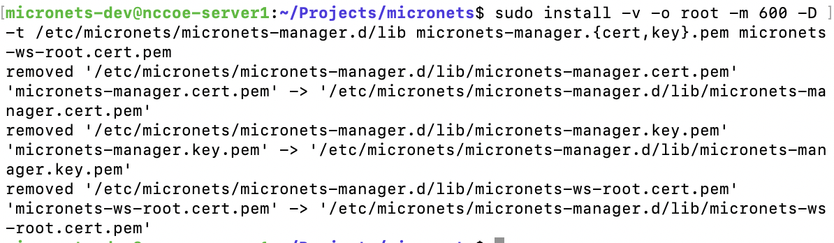
Create a placeholder micronets-ws-proxy.pkeycert.pem file. This file is not used, but the Micronets Manager currently checks for it:
sudo touch /etc/micronets/micronets-manager.d/lib/micronets-ws-proxy.pkeycert.pem
Copy the shared secret value generated during the MSO portal installation:
sudo install -v -o root -g docker -m 660 -D -t /etc/micronets/micronets-manager.d/lib mso-auth-secret
You should see output similar to the following:

Execute the following command to download the Micronets Manager docker image. (Note: If you cannot connect to the docker service, use sudo usermod -aG docker to add the user account to the docker group.)
/etc/micronets/micronets-manager.d/mm-container pullYou should see output similar to the following:
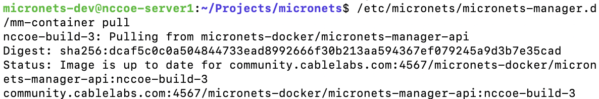
Complete the following step to configure NGINX for the Micronets Manager:
The Micronets Manager management script creates NGINX forward entries that provide a unique URI for each Micronets Manager docker image. To create the infrastructure for these entries, run:
sudo /etc/micronets/micronets-manager.d/mm-container setup-web-proxyYou should see output similar to the following:
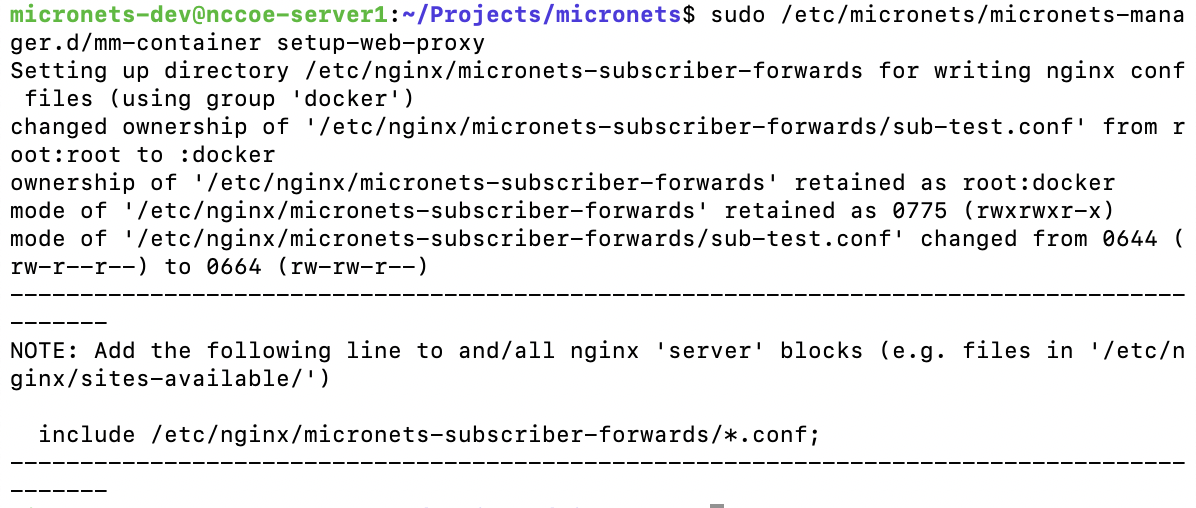
This sets up the folder to dynamically create forwarding entries for Micronets Manager instances as they are created/removed. But the site files in /etc/nginx/sites-available/ need the following added to the server blocks to enable forwarding subscriber operations to the correct docker container.
Open the NGINX sites-available file created in:
sudo vim /etc/nginx/sites-available/nccoe-server1.micronets.netAdd the following entry to the file:
include /etc/nginx/micronets-subscriber-forwards/*.conf;For example:
server {
   server_name nccoe-server1.micronets.net;
   {…]
   include /etc/nginx/micronets-subscriber-forwards/*.conf;
}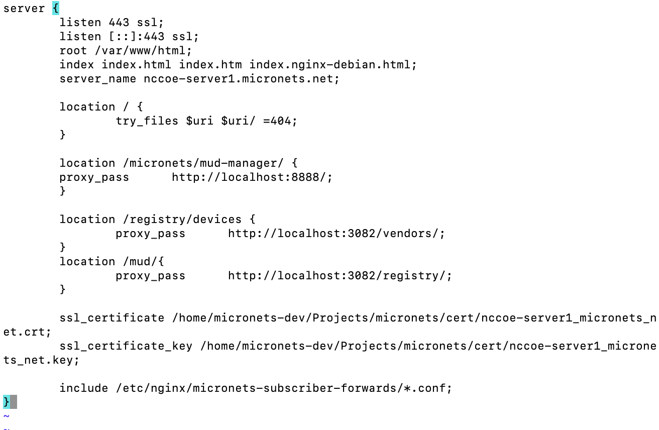
Complete the following steps to configure the Micronets Manager to communicate with other Micronets services on the server:
Open the docker-compose.yml file by entering the following command:
sudo vim /etc/micronets/micronets-manager.d/docker-compose.ymlModify the following environmental variables in the docker-compose.yml file. Replace <ServerURL> with your server URL:
MM_API_PUBLIC_BASE_URL: https://\ **<ServerURL>**/sub/${MM_SUBSCRIBER_ID}/api

MM_APP_PUBLIC_BASE_URL: https:// **<ServerURL>**/sub/${MM_SUBSCRIBER_ID}/app

MM_IDENTITY_SERVER_BASE_URL: https://\ **<ServerURL>**:8888/

MM_MSO_PORTAL_BASE_URL: https:// **<ServerURL>**/micronets/mso-portal

MM_MUD_MANAGER_BASE_URL: https:// **<ServerURL>**/micronets/mud-manager

MM_MUD_REGISTRY_BASE_URL: https:// **<ServerURL>**/micronets/mud/v1

MM_GATEWAY_WEBSOCKET_BASE_URL: wss://\ **<ServerURL>**:5050/micronets/v1/ws-proxy/gw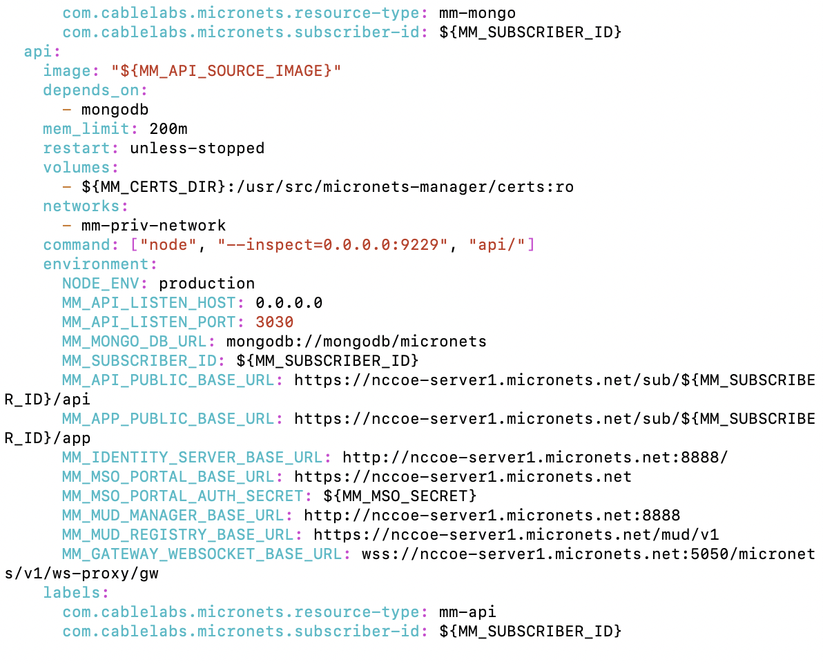
4.1.10 Micronets Websocket Proxy
This section describes the CableLabs Micronets Websocket Proxy, which, for this implementation, is a cloud-provided service. This implementation leverages the nccoe-build-3 branch of CableLabs Micronets Websocket Proxy Git release. This service can be hosted by the implementer or another party. This documentation describes setting up your own Micronets Manager.
4.1.10.1 Micronets Websocket Proxy Overview
The Micronets Websocket Proxy is a service for establishing a Websocket connection between a subscriberʼs gateway and Micronets Manager. This connection is leveraged to issue representational state transfer (REST) commands to the gateway and to receive event notifications from the gateway.
4.1.10.2 Configuration Overview
The following subsections document the software and network configurations for the Websocket Proxy. Please note that the MUD manager, Micronets Manager, Websocket Proxy, MUD registry, and MSO portal are all implemented on the same server, nccoe-server1.micronets.net. Many of these configurations are already covered in previous sections of this document but are repeated here for consistency.
4.1.10.2.1 Network Configuration
This server was hosted outside the lab environment on a Linode cloud-hosted Linux server. Its IP address was statically assigned.
4.1.10.2.2 Software Configuration
For this build, the server ran on an Ubuntu 18.04 LTS operating system. The Websocket Proxy runs in its own docker container and is configured to use SSL/TLS encryption.
The following software is required to install, configure, and operate the Websocket Proxy:
an Ubuntu 18.04 LTS server reachable by the Micronets Manager and any Micronets gateways
docker (v18.06 or higher)
docker-compose (v1.23.1 or higher)
curl
Python 3.6+
Python virtualenv package
4.1.10.2.3 Hardware Configuration
The following hardware is required to install, configure, and operate the Websocket Proxy:
4 GB of RAM
50 GB of free disk space
4.1.10.3 Setup
Change to the working directory by entering the following command:
cd Projects/micronets/If you have not already created this directory:
Execute the following command:
mkdir Projects/micronets/Next, change directories by entering the following command:
cd Projects/micronets/
Download and install the cert generation scripts by executing the following commands:
Download the script to generate the root certificates:
curl -s -Ohttps://raw.githubusercontent.com/cablelabs/micronets-ws-proxy/nccoe-build-3/bin/gen-root-certDownload the script to generate leaf certificates:
curl -s -Ohttps://raw.githubusercontent.com/cablelabs/micronets-ws-proxy/nccoe-build-3/bin/gen-leaf-certInstall both scripts by executing the following command:
sudo install -v -o root -m 755 -D -t /etc/micronets/micronets-ws-proxy.d/ gen-*-cert
You should see output similar to the following:
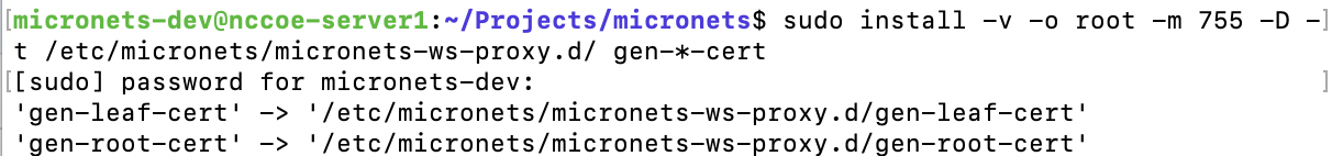
Create the root certificate for the Websocket Proxy:
/etc/micronets/micronets-ws-proxy.d/gen-root-cert --cert-basename micronets-ws-root \
  --subject-org-name "Micronets Websocket Root Cert" \
  --expiration-in-days 3650
You should see output similar to the following:
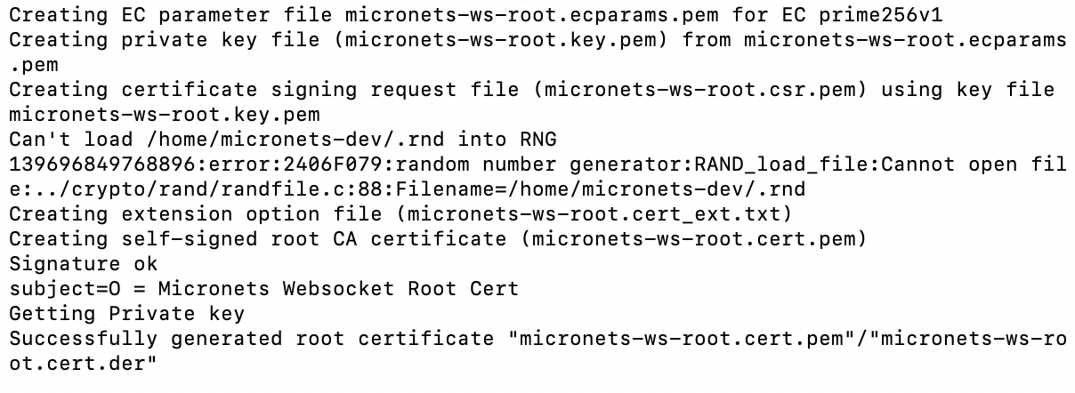
Create the Websocket Proxyʼs server certificate and private key by entering the following command. (Note: This certificate and key host the Websocket Proxy server.)
/etc/micronets/micronets-ws-proxy.d/gen-leaf-cert --cert-basename micronets-ws-proxy \
   --subject-org-name "Micronets Websocket Proxy Cert" \
   --expiration-in-days 3650 \
   --ca-certfile micronets-ws-root.cert.pem \
   --ca-keyfile micronets-ws-root.key.pem
You should see output similar to the following:
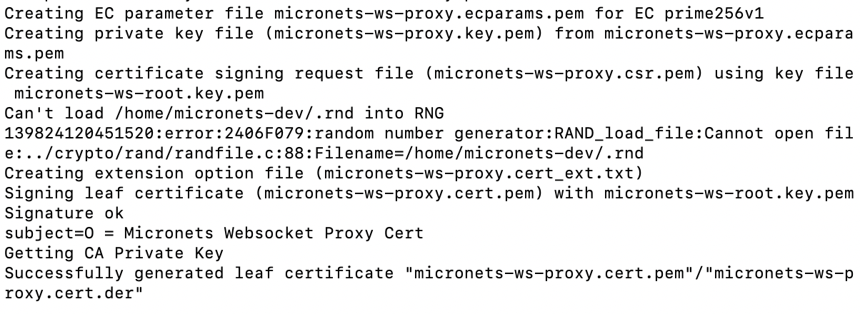
Combine the private key and certificate into one file by entering the following command:
cat micronets-ws-proxy.cert.pem micronets-ws-proxy.key.pem \
   > micronets-ws-proxy.pkeycert.pem
Generate the client certificate and key to be used by the Micronets Manager to connect to the Websocket Proxy. (Note: these files will enable the Micronets Manager to connect to the proxy.)
/etc/micronets/micronets-ws-proxy.d/gen-leaf-cert --cert-basename micronets-manager \
   --subject-org-name "Micronets Manager Websocket Client Cert" \
   --expiration-in-days 3650 \
   --ca-certfile micronets-ws-root.cert.pem \
   --ca-keyfile micronets-ws-root.key.pem
You should see output similar to the following:
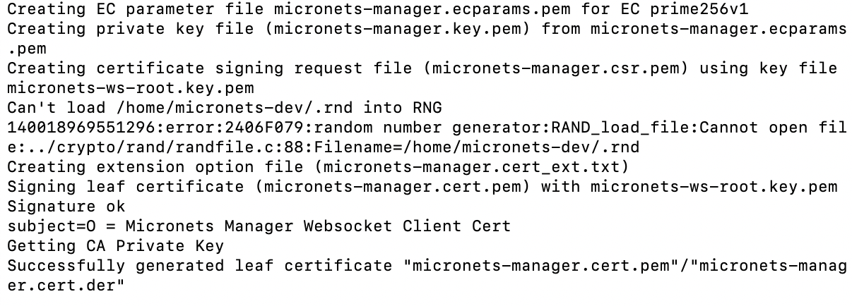
Combine the private key and certificate into one file by entering the following command:
cat micronets-manager.cert.pem micronets-manager.key.pem \
   > micronets-manager.pkeycert.pem
Generate the certificate and key to be used by the Micronets Gateway to connect to the Websocket Proxy. (Note: these files will enable the Micronets Gateway to connect to the proxy.)
/etc/micronets/micronets-ws-proxy.d/gen-leaf-cert --cert-basename micronets-gw-service \
   --subject-org-name "Micronets Gateway Service Websocket Client Cert" \
   --expiration-in-days 3650 \
   --ca-certfile micronets-ws-root.cert.pem \
   --ca-keyfile micronets-ws-root.key.pem
You should see output similar to the following:
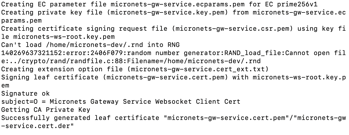
Combine the private key and certificate into one file by entering the following command:
cat micronets-gw-service.cert.pem micronets-gw-service.key.pem \
   > micronets-gw-service.pkeycert.pem
Download and install the management script by entering the following commands:
Download the micronets-ws-proxy script:
curl -s -Ohttps://raw.githubusercontent.com/cablelabs/micronets-ws-proxy/nccoe-build-3/bin/micronets-ws-proxyInstall the script to the appropriate directory:
sudo install -v -o root -m 755 -D -t /etc/micronets/micronets-ws-proxy.d/ micronets-ws-proxy
You should see output similar to the following:

Copy the Websocket Proxy server cert and key for use by the Websocket Proxy docker container:
sudo install -v -o root -m 600 -D -t /etc/micronets/micronets-ws-proxy.d/lib \
micronets-ws-proxy.pkeycert.pem micronets-ws-root.cert.pem
You should see output similar to the following:
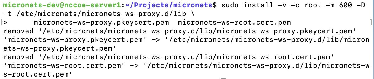
Download the Micronets Websocket Proxy docker image. (Note: if you cannot connect to the docker service, use sudo usermod -aG docker to add the user account to the docker group.)
/etc/micronets/micronets-ws-proxy.d/micronets-ws-proxy docker-pullYou should see output similar to the following:
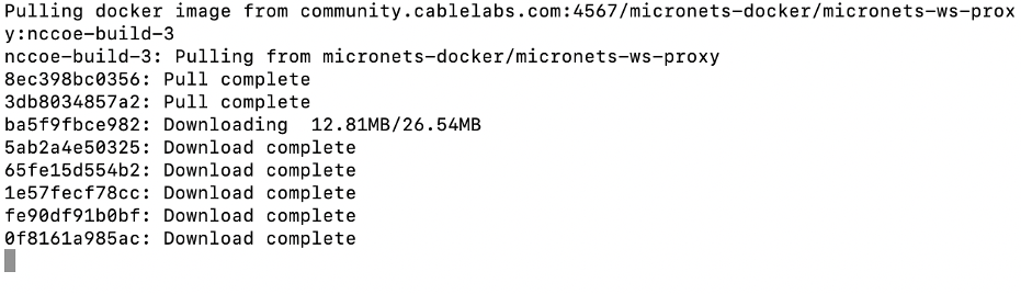
Start the Websocket Proxy:
/etc/micronets/micronets-ws-proxy.d/micronets-ws-proxy docker-runYou should see output similar to the following:
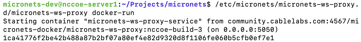
Verify that the Websocket Proxy is running:
/etc/micronets/micronets-ws-proxy.d/micronets-ws-proxy docker-logsYou should see output similar to the following:
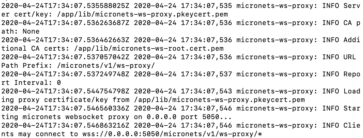
Verify the Websocket Proxy credentials by executing the following steps:
Download the Websocket test client script:
curl -Ohttps://raw.githubusercontent.com/cablelabs/micronets-ws-proxy/nccoe-build-3/bin/websocket-test-client.pyDownload the requirements text file:
curl -Ohttps://raw.githubusercontent.com/cablelabs/micronets-ws-proxy/nccoe-build-3/requirements.txtClear out the nonroot installation of virtualenv, and set the Python interpreter to use Python 3.6 for the script installation:
virtualenv --clear -p $(which python3.6) $PWD/virtualenvYou should see output similar to the following:
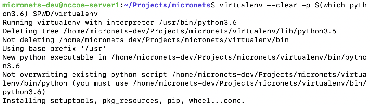
Install virtualenv and pass the requirements text file:
./virtualenv/bin/pip install -r requirements.txtYou should see output similar to the following:
Run the Websocket test client script:
./virtualenv/bin/python websocket-test-client.py \
   --client-cert micronets-manager.pkeycert.pem \
   --ca-cert micronets-ws-root.cert.pem \
   wss://localhost:5050/micronets/v1/ws-proxy/test/mm
You should see output similar to the following:
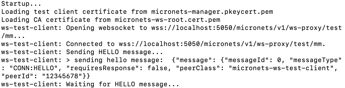
Verify communication from the test client to the Websocket Proxy by checking the logs:
/etc/micronets/micronets-ws-proxy.d/micronets-ws-proxy docker-logsYou should see output similar to the following:
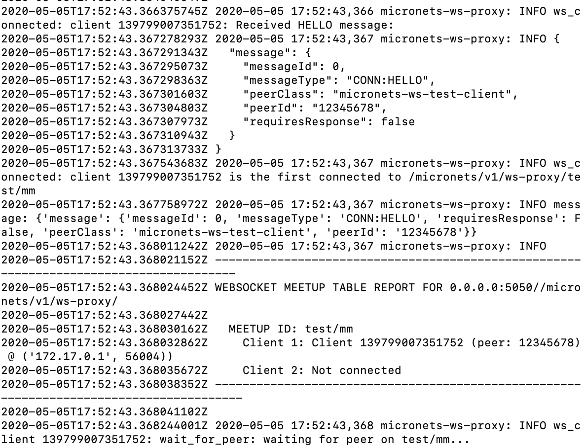
Save the micronets-manager.pkeycert.pem, micronets-gw-service.pkeycert.pem, and micronets-ws-root.cert.pem files for configuring the Micronets Manager and Micronets Gateway components.
4.1.11 Micronets iPhone Application for Device Onboarding
This section describes the CableLabs Micronets iPhone application, which is a mobile application used for onboarding DPP-capable devices. This implementation leverages the latest CableLabs Micronets iPhone application Git release. This documentation describes setting up your own Micronets iPhone application.
4.1.11.1 Micronets iPhone Application Overview
The Micronets iPhone application is responsible for sending onboarding requests and related elements to the MSO portal when the user initiates the onboarding process on the Micronets Proto-Pi device and scans the QR code. If building with an Android phone, follow the documentation provided here: https://github.com/cablelabs/micronets-mobile/blob/nccoe-build-3/README.md#android
4.1.11.2 Configuration Overview
The following subsections document the software and network configurations for the Micronets iPhone application.
4.1.11.2.1 Network Configuration
The mobile phone on which the Micronets application is being installed should have internet access via either the cellular network or Wi-Fi.
4.1.11.2.2 Software Configuration
The following software is required to install, configure, and operate the Micronets iPhone application:
macOS (minimum version 10.13; High Sierra)
Apple iOS Developer license
Node (minimum version 8)
Cordova (version 8.0.0; problems with version 9)
Xcode (minimum version 9.2)
ImageMagick
Brew
4.1.11.2.3 Hardware Configuration
The following hardware is required to install, configure, and operate the Micronets iPhone application:
Apple computing system (laptop or desktop)
Apple iPhone (any model compatible with iOS 10.3 and above)
4.1.11.3 Setup
4.1.11.3.1 Install Dependencies
Install Node by entering the following command in the terminal:
brew install nodeInstall ImageMagick by entering the following command in the terminal:
brew install imagemagickInstall Cordova version 8.0.0 by entering the following command:
sudo npm install -g cordova@8.0.0Install ios-deploy, which Cordova uses to cable-load the application, by entering the following command:
sudo npm install -g --unsafe-perm=true ios-deployNote: The unsafe-perm flag is required on macOS versions El Capitan and higher.
If you run into an EACCES: permission denied error, attempt the following fixes:
sudo chown -R $USER:$GROUP ~/.npmsudo chown -R $USER:$GROUP ~/.configOpen Xcode, and add Xcode to your command-line tools:
Preferences > Location > Command Line Tools
Select your Xcode version as seen in screenshot below:
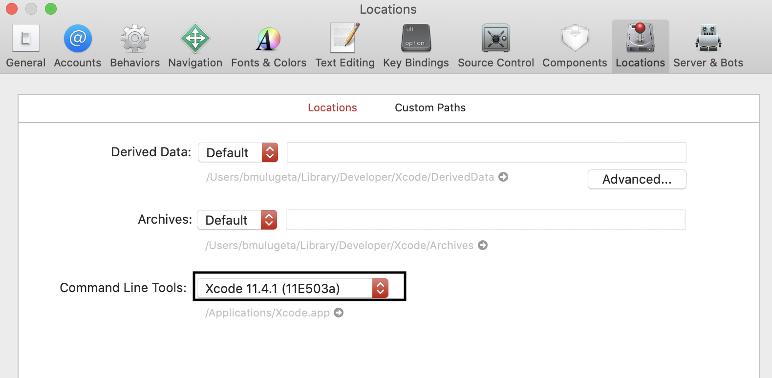
4.1.11.3.2 Build Micronets iPhone Application
Check out the repo that contains the Micronets mobile application build by entering the following command:
git clonehttps://www.github.com/cablelabs/micronets-mobile.git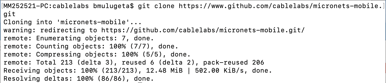
Enter the Micronets mobile directory by entering the following command:
cd micronets-mobileAdd the target platform by entering the following command:
cordova platform add ios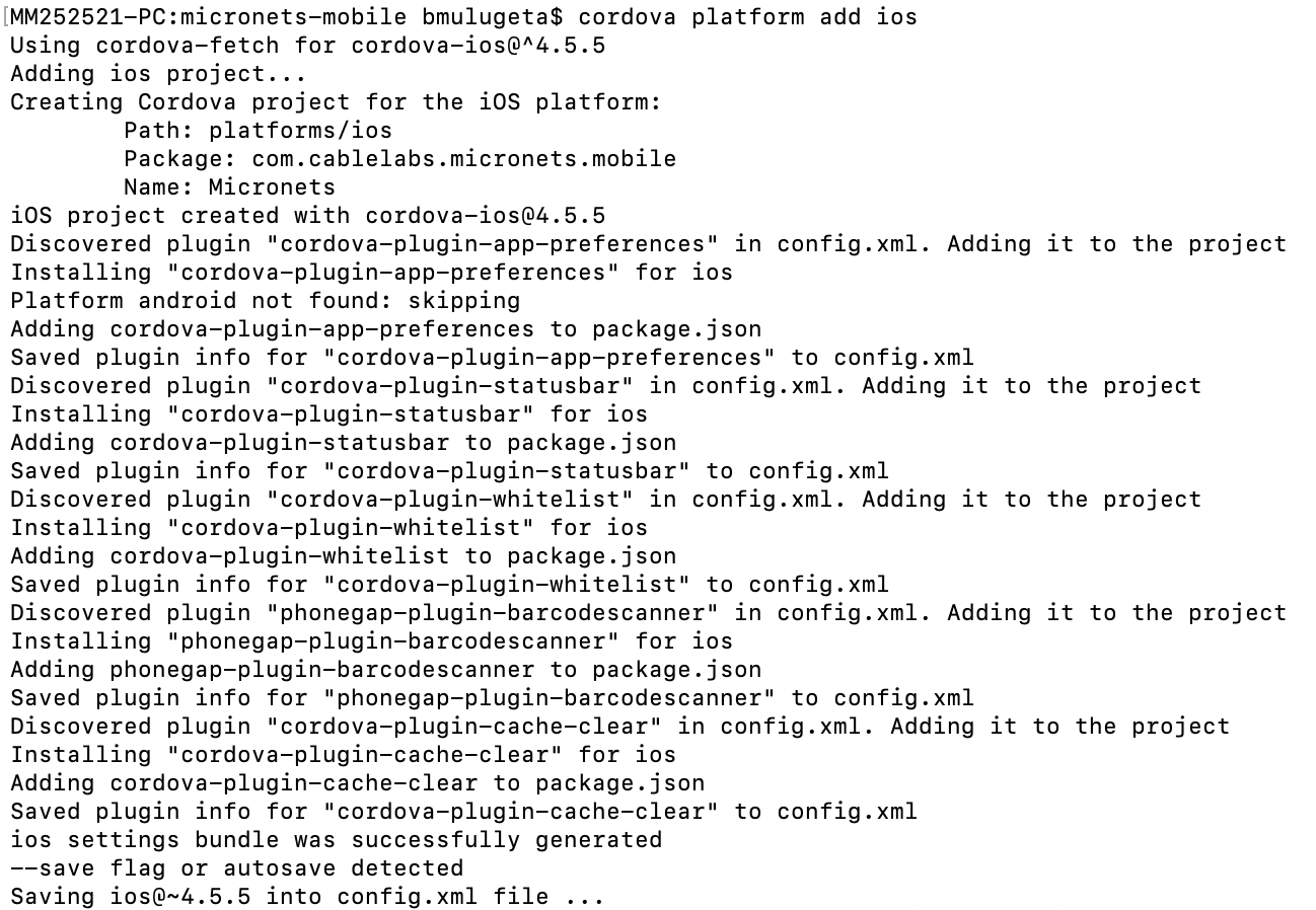
Generate iOS icon set by entering the following command:
npx app-icon generateYou should see the following output:
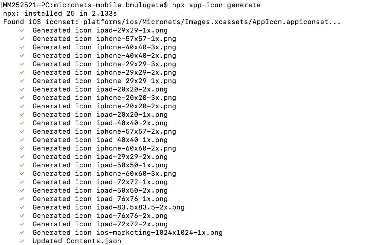
Plug your iPhone into your computer, unlock your phone, and open to home screen. (You will need to allow developer use of the phone. You will be prompted.)
Run the following command to build the mobile application:
cordova run ios --device --buildFlag='-UseModernBuildSystem=0'You should see output similar to the following:
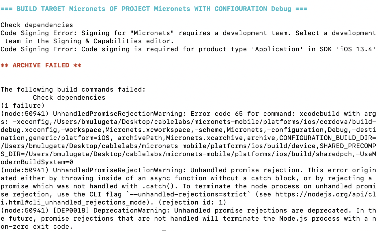
Note: This initial attempt to build is expected to fail. It is necessary to open the project in Xcode and change some settings.
Open the project file platforms/ios/Micronets.xcodeproj in Xcode.
Click the Micronets icon in the navigator pane on the left. The properties pane should now be visible on the right:
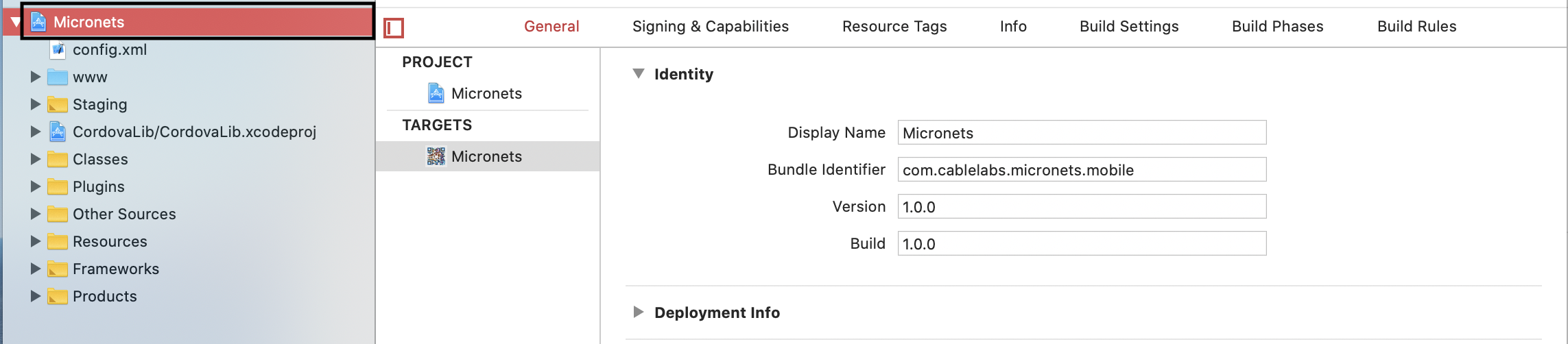
Select Micronets under TARGETS:
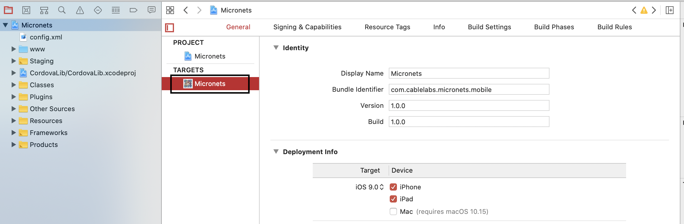
Select the Signing & Capabilities tab in the heading:

Ensure Automatically manage signing is checked:
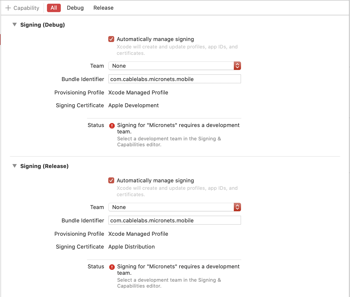
You will see the following notification. Select Enable Automatic:
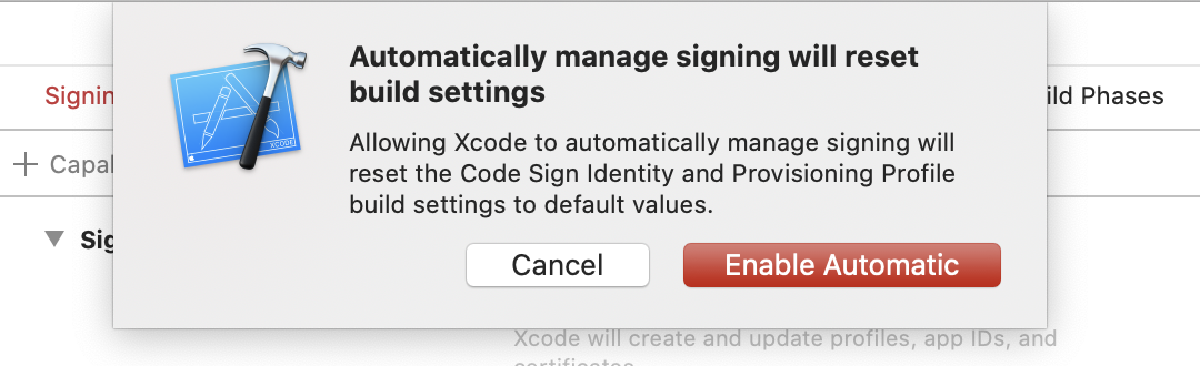
The Automatically manage signing setting should now be selected as seen below:
Ensure that your team is selected under the Team drop-down:

Note: If you encounter the following error to register the bundle identifier, proceed to step a:
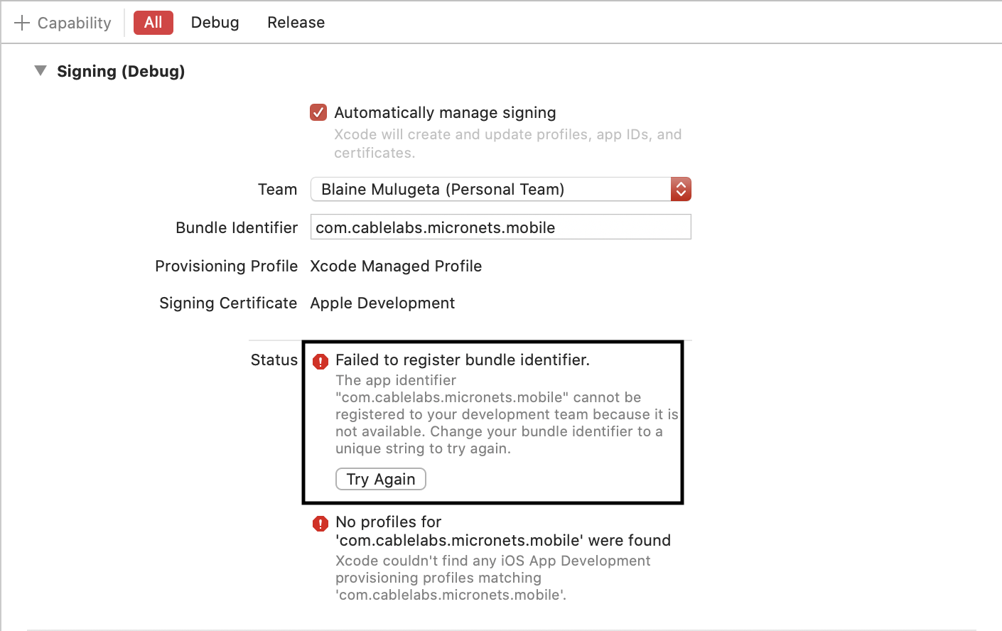
Change the Bundle Identifier to your own unique identifier:
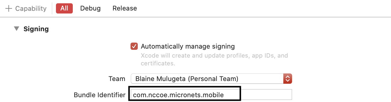
Navigate to the config.xml file by selecting as shown below:
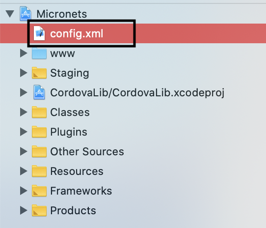
Modify the widget id from com.cablelabs.micronets.mobile to the build identifier created in step a as seen below:
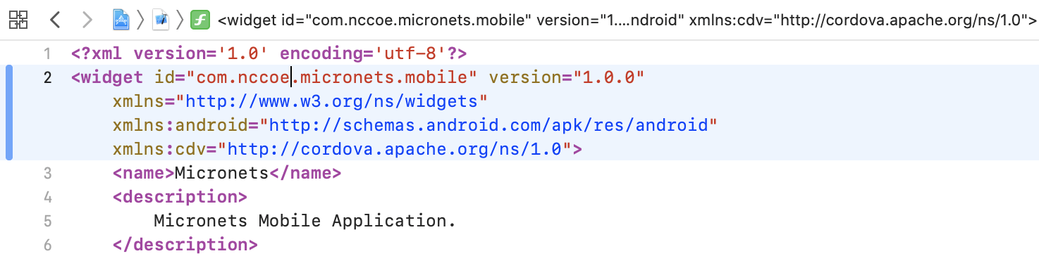
Select the General tab in the heading:
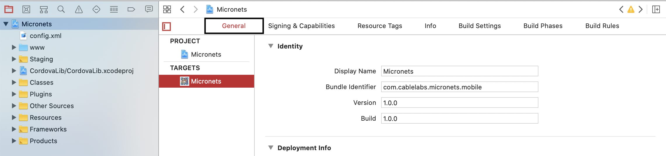
Under Deployment Info, make the following modifications:
Select the deployment Target (suggested 10.3)
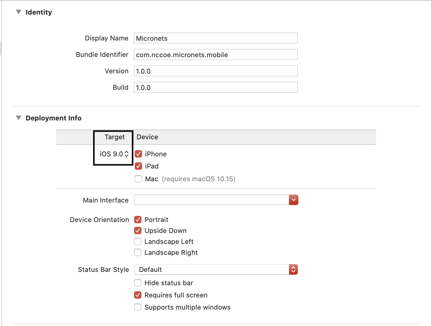
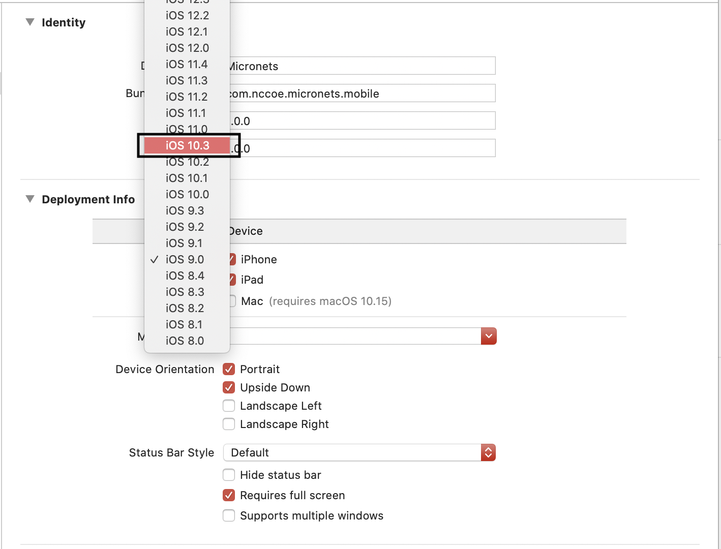
Select Device type iPhone and iPad, Device Orientation Portrait and Upside Down, Status Bar style Hide status bar:
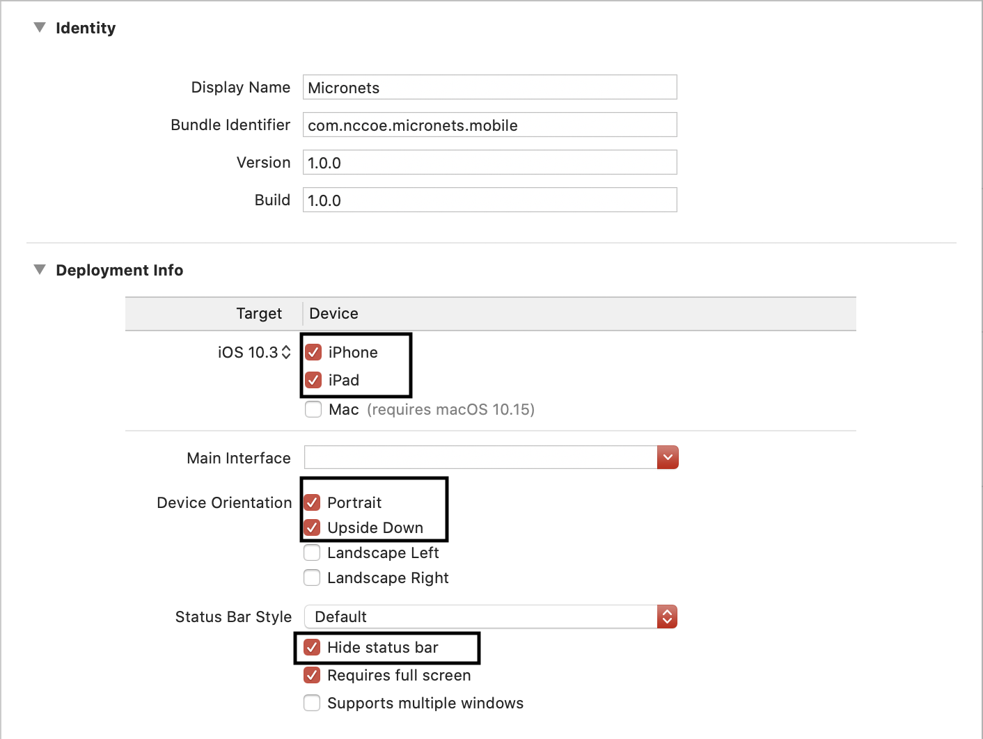
Select the Info tab, and make the following modifications:

On the last entry in Custom iOS Target Properties, hover over the down arrow.
A plus sign appears. Click it to create a new property.
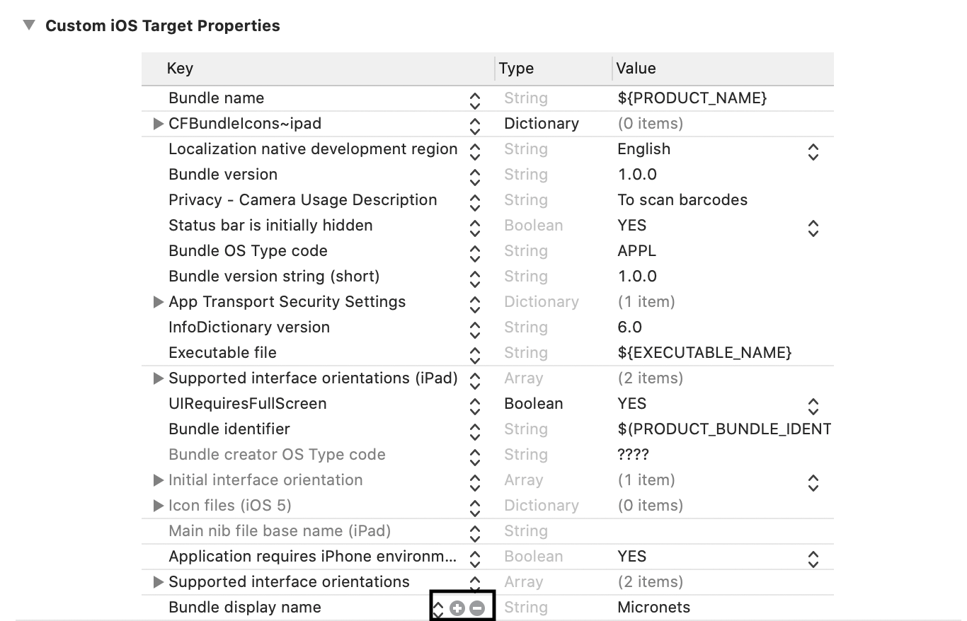
In the combo box drop-down, start typing View controller, and choose the auto-fill suggestion View controller-based status bar appearance:
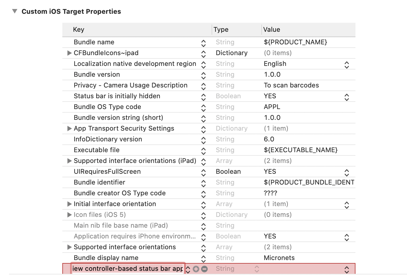
Click enter to add this entry. Ensure this entry is set to NO.
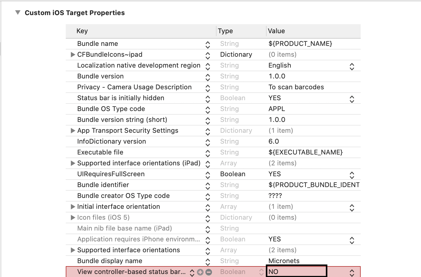
Return to the terminal, and run the following command (ensure the iPhone is unlocked first):
cordova run ios --device --buildFlag='-UseModernBuildSystem=0'Note: You may see an UnhandledPromiseRejectionWarning as seen below, but the application should still have been loaded onto your iPhone:
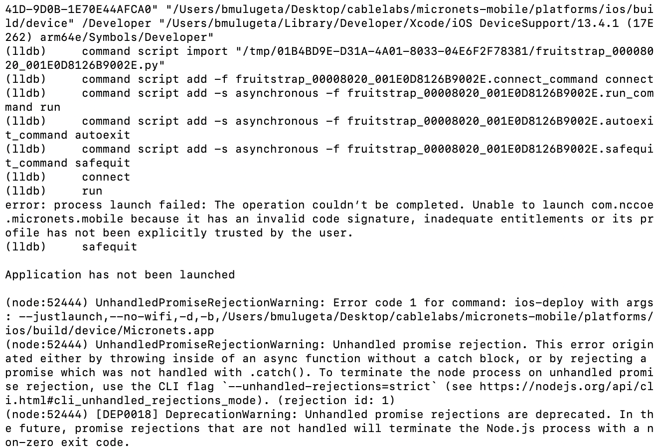
4.1.12 MSO Portal Bootstrapping Interface to the Onboarding Manager
This section describes the CableLabs Micronets MSO portal, which, for this implementation, is a cloud-provided service. This implementation leverages the nccoe-build-3 branch of CableLabs Micronets MSO portal Git release. This service can be hosted by the implementer or another party. This documentation describes setting up your own MSO portal.
4.1.12.1 MSO Portal Overview
The MSO portal is the interface between the Micronets iPhone application and the Micronets Manager. It is responsible for passing onboarding requests and respective onboarding information to the Micronets Manager to complete the request.
4.1.12.2 Configuration Overview
The following subsections document the software and network configurations for the MSO portal. Please note that the MUD manager, Micronets Manager, Websocket Proxy, MUD registry, and MSO portal are all implemented on the same server, nccoe-server1.micronets.net. Many of these configurations are already covered in previous sections of this document but are repeated here for consistency.
4.1.12.2.1 Network Configuration
This server was hosted outside the lab environment on a Linode cloud-hosted Linux server. Its IP address was statically assigned.
4.1.12.2.2 Software Configuration
The following software is required to install, configure, and operate the MSO portal:
docker (v18.06 or higher)
docker-compose (v1.23.1 or higher)
OpenSSL (1.0.2g or higher)
NGINX and requisite certificates if https is to be supported
4.1.12.2.3 Hardware Configuration
The following hardware is required to install, configure, and operate the MSO portal:
4 GB of RAM
50 GB of free disk space
4.1.12.3 Setup
4.1.12.3.1 Install Dependencies
Install docker, docker-compose, openssl, and NGINX by entering the following command:
sudo apt-get install docker docker-compose openssl nginx
4.1.12.3.2 Install and Configure MSO Portal
Install a newer version of docker-compose, if necessary. (Ubuntu 18.04 comes with an older version.)
Check the current version by entering the following command:
docker-compose --versionThe result should be similar to the following:
If the version is earlier than v1.23.1, run the following commands to install a new version in /usr/local/bin:
Download the docker compose utility:
curl -L -O https://github.com/docker/compose/releases/download/1.24.1/docker-compose-Linux-`uname -m’
Install the docker compose utility into the appropriate directory:
sudo install -v -o root -m 755 docker-compose-Linux-`uname -m\` /usr/local/bin/docker-compose
The result should be similar to the following:
Download and install the MSO portal management script by entering the following commands:
Download the MSO portal management script by executing the following command:
curl -Ohttps://raw.githubusercontent.com/cablelabs/micronets-mso-portal/nccoe-build-3/scripts/mso-portalDownload the docker-compose.yml file by executing the following command:
curl -Ohttps://raw.githubusercontent.com/cablelabs/micronets-mso-portal/nccoe-build-3/scripts/docker-compose.ymlInstall the MSO portal management script to the appropriate directory by executing the following command:
sudo install -v -o root -m 755 -D -t /etc/micronets/mso-portal.d mso-portalThe result should be similar to the following:

Install the docker-compose.yml management script to the appropriate directory by executing the following command:
sudo install -v -o root -m 644 -D -t /etc/micronets/mso-portal.d docker-compose.yml
The result should be similar to the following:

Note: The MSO portal management script contains default values that can be modified directly in your copy of the management script or overridden via command-line parameters. Run /etc/micronets/mso-portal.d –help to see the options.
Download the MSO portal docker image by executing the following command. (Note: If you cannot connect to the docker service, you can use sudo usermod -aG docker <username> to add the user account to the docker group.)
/etc/micronets/mso-portal.d/mso-portal docker-pullThe result should be similar to the following:
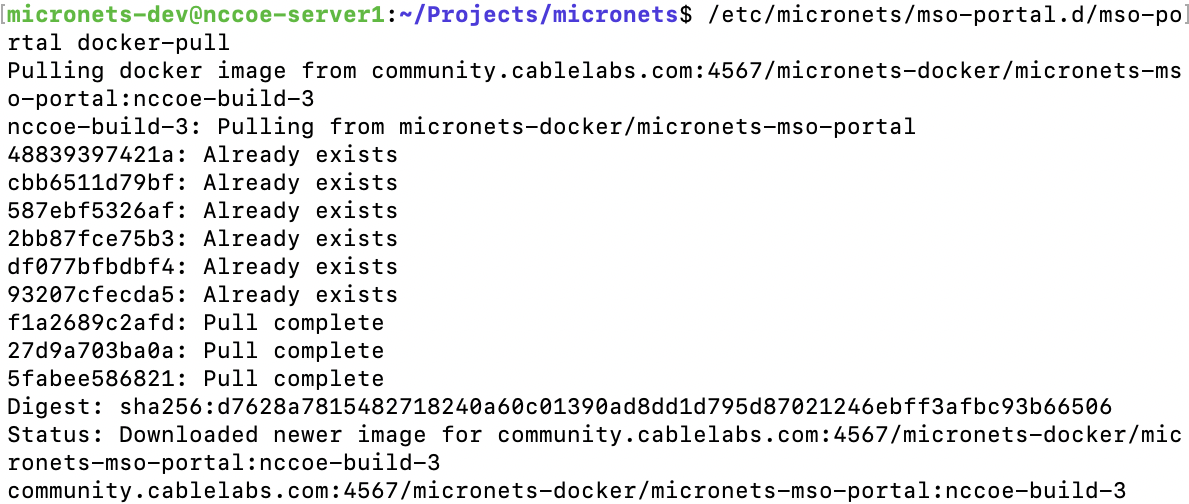
Generate a shared secret for enabling communication between the Micronets Manager instances and the MSO portal:
sudo /etc/micronets/mso-portal.d/mso-portal create-mso-secretThe result should be similar to the following:
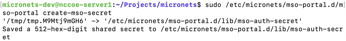
Note: This value will need to be copied to the Micronets Manager host server to allow Micronets Manager instances to access the MSO portal APIs.
Configure MSO portal URLs:
Open the mso-portal file by entering the following command:
sudo vim /etc/micronets/mso-portal.d/mso-portalModify the parameters of the MSO portal management script to reflect the public end points of the MSO portal service. For example:
The DEF_MSO_API_BASE_URL path variable can be set to:
DEF_MSO_API_BASE_URL="https://nccoe-server1.micronets.net/micronets/mso-portal/"
The DEF_WS_PROXY_BASE_URL path variable can be set to:
DEF_WS_PROXY_BASE_URL="wss://nccoe-server1.micronets.net:5050/micronets/v1/ws-proxy/gw"
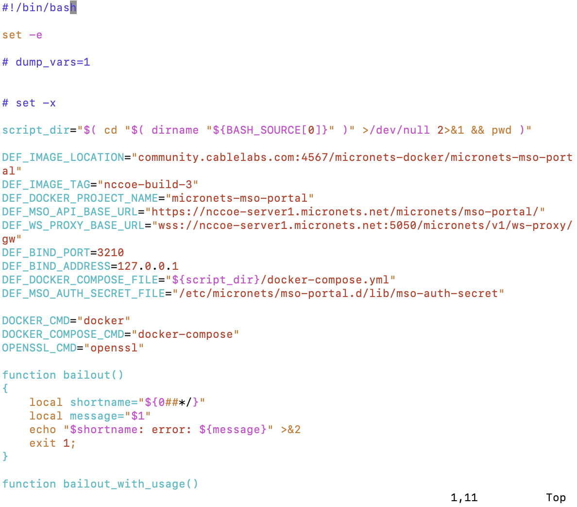
Start the MSO portal docker image by executing the following command:
sudo /etc/micronets/mso-portal.d/mso-portal docker-runThe result should be similar to the following:
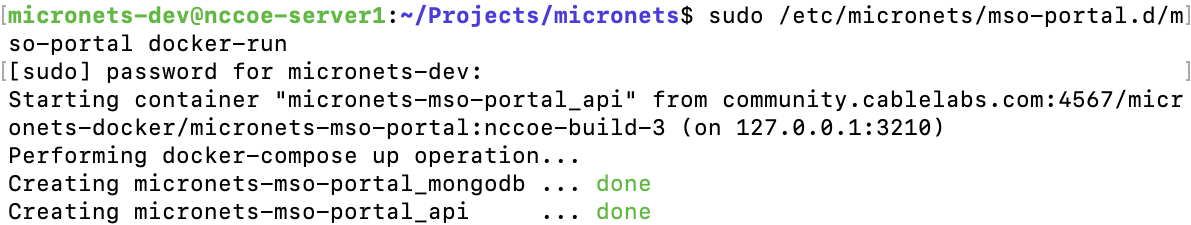
Verify that the MSO portal started successfully by executing the following command:
/etc/micronets/mso-portal.d/mso-portal docker-logsYou should see output like the following at the end of the log:
Feathers application started on “http://0.0.0.0:3210”
Feathers webSocketBaseUrl “wss://<ServerURL>:5050/micronets/v1/ws-proxy/gw”
Feathers publicApiBaseUrl “https://< ServerURL>/micronets/mso-portal/”
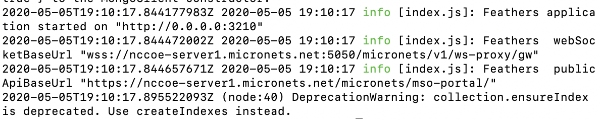
To securely expose the MSO API, configure your NGINX server block to allow the https proxy to redirect to localhost port 3210:
Open the NGINX sites-available file for the server:
sudo vim /etc/nginx/sites-available/nccoe-server1.micronets.netAdd the following location to the server block:
server {
      […]
   location /micronets/mso-portal/ {
      proxy_pass http://127.0.0.1:3210/;
   }
      […]
}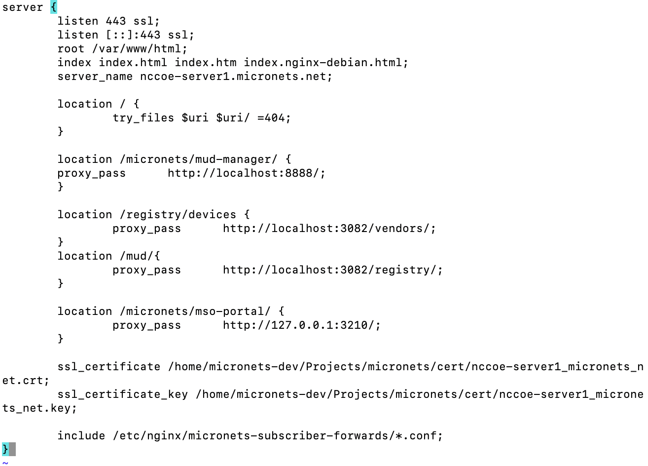
4.2 Product Integration and Operation
This section details integration and operation of the Micronets components that were previously installed in the product installation section. Please ensure that the components from that section are installed as described before proceeding to the following sections.
4.2.1 Adding an MSO Subscriber
This section describes adding an MSO portal subscriber. This subscriber account will allow a valid connection and association among the Micronets mobile application, Micronets Gateway, and Micronets services.
4.2.1.1 Prerequisites
To successfully complete this section, complete the product installation section.
4.2.1.2 Instructions
Add a subscriber and associated user account and password to the MSO portal by entering the following command. (Note: be sure to use the server URL that reflects the location of your MSO portal.)
curl -s -X POST https://nccoe-server1.micronets.net/micronets/mso-portal/portal/v1/subscriber \
   -H "Content-Type: application/json" \
   -d '{
      "id" : "subscriber-001",
      "ssid" : "micronets-gw",
      "name" : "Subscriber 001",
      "gatewayId":"micronets-gw",
      "username":"micronets",
      "password":"micronets"
   }' \
| json_pp
You should see output similar to the following:
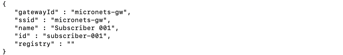
Start the Micronets Manager for the subscriber by executing the following command:
sudo /etc/micronets/micronets-manager.d/mm-container start subscriber-001You should see output similar to the following:
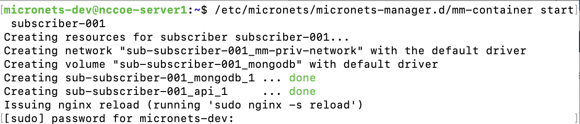
Check the logs to confirm that the Micronets Manager for the new subscriber started successfully by executing the following command:
/etc/micronets/micronets-manager.d/mm-container logs subscriber-001You should see output similar to the following:
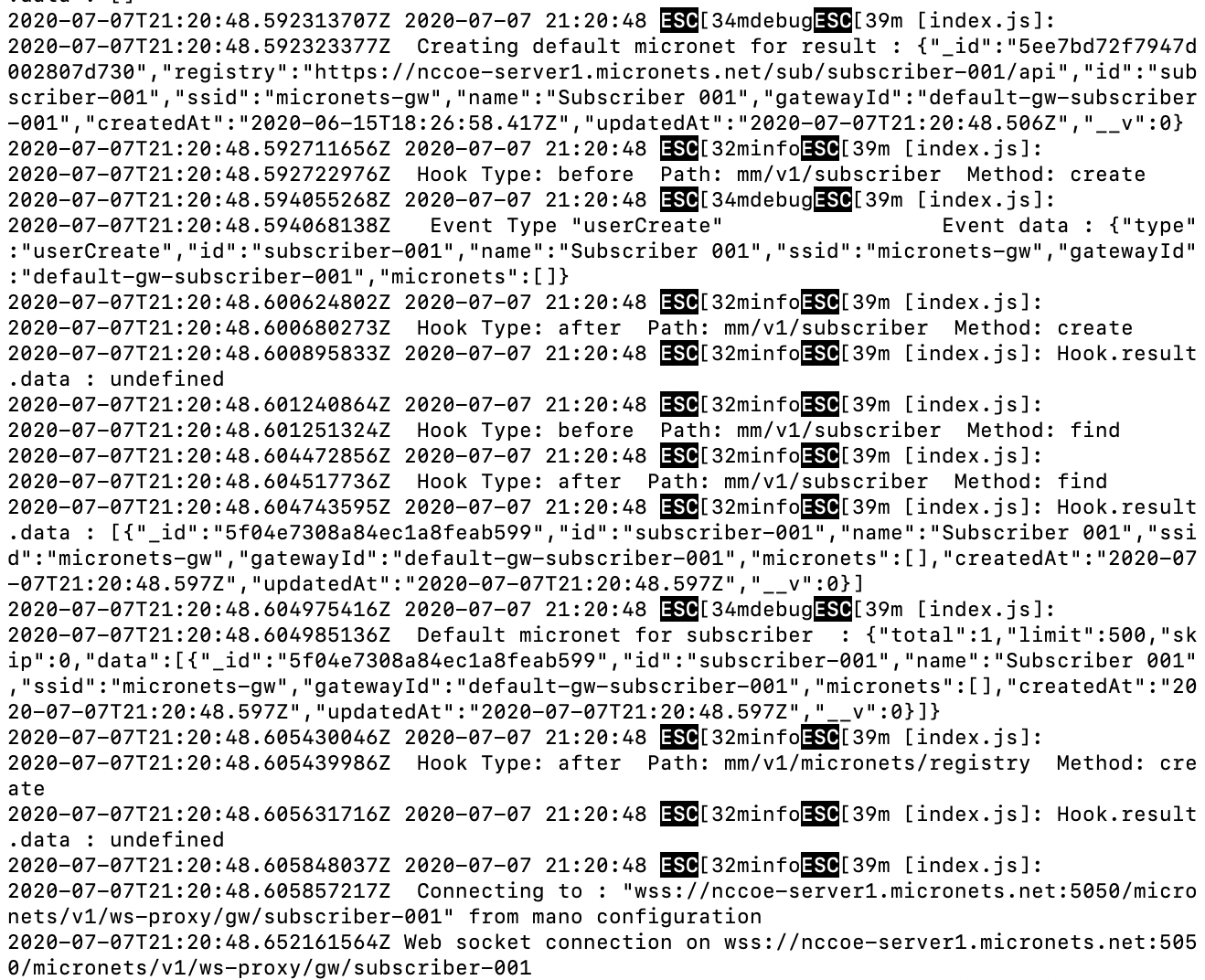
Verify that the Micronets Manager for the subscriber has registered with the MSO portal by executing the following command:
curl -s https://my-server.org/micronets/mso-portal/portal/v1/subscriber/subscriber-001 | json_pp
You should see output similar to the following:
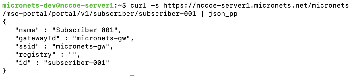
4.2.2 Associating the Micronets Gateway with a Subscriber
This section describes associating an MSO portal subscriber with the Micronets Gateway. For additional instructions not detailed in this documentation, please follow the link to the CableLabs documentation: https://github.com/cablelabs/micronets-gw/releases/tag/1.0.62-u18.04 (for Micronets Gateway configuration) and https://github.com/cablelabs/micronets/blob/nccoe-build-3/docs/operation/gateway-4subscriber.md (for operations documentation).
4.2.2.1 Prerequisites
To successfully complete this section, complete the product installation section and complete Section 4.2.1. Ensure that all steps have been successfully completed before proceeding to the instructions.
4.2.2.2 Instructions
Create the /etc/network/interfaces file on the Micronets Gateway:
Open a terminal on the Micronets Gateway. If this is the first installation of the Micronets Gateway, copy the sample interfaces file to your /etc/network/interfaces file by entering the following command:
sudo cp /opt/micronets-gw/doc/interfaces.sample /etc/network/interfacesModify the /etc/network/interfaces file:
Retrieve the desired interface names on the gateway by running the following command in a terminal on the gateway:
ifconfigConfigure your wireless and wired interface by renaming the corresponding portion of the file to reference the respective interface name, as seen in the config below:
#
# A wired interface managed by the Micronets gateway
#
allow-brmn001 enp1s0
iface enp1s0 manual
  ovs_type OVSPort
  ovs_bridge brmn001
  ovs_port_req 4
  ovs_port_initial_state blocked
#
# A wireless interface managed by the Micronets gateway
#
allow-brmn001 wlp2s0
iface wlp2s0inet manual
  ovs_type OVSPort
  ovs_bridge brmn001
  ovs_port_req 3
  ovs_port_initial_state blocked
Confirm that the bridge entry contains an ovs_ports line referring to the micronet interfaces (enp1s0 and wlp2s0) as seen in the config below:
auto brmn001
allow-ovs brmn001
iface brmn001 inet manual
  ovs_type OVSBridge
  ...
# the ovs_ports should list all wired and wireless interfaces under Micronets management
  ovs_ports diagout1 enp1s0 wlp2s0
  ...
Confirm that the entry in the interfaces file for the wired interface is set up correctly for the network to supply the uplink (the uplink interface is enp1s0) and get its address via DHCP so the configuration is similar to the following:
#
# The uplink port
#
auto eth enp1s0
iface eth0inet dhcp
Confirm that the bridge entry contains an ovs_bridge_uplink_port line referring to the uplink interface as seen in the config below:
auto brmn001
allow-ovs brmn001
iface brmn001 inet manual
  ovs_type OVSBridge
  ...
  # This is the port that's connected to the Internet
  ovs_bridge_uplink_port enp1s0
  ...
Reboot the gateway to apply the changes to the /etc/network/interfaces file by executing the following command:
sudo reboot
Create a gateway configuration file for the Micronets Gateway to register for the subscriber:
Copy and save the MAC addresses and corresponding interface names output by executing the following command:
ifconfigNavigate to the /etc/network/interfaces file on the gateway, and copy the subnets configurations, which will be used for the gateway configuration file in the following steps:
sudo vim /etc/network/interfacesCopy and save the subnet and ranges associated with the interfaces identified in the previous step from this file. (Note: these are at the bottom of the file.)
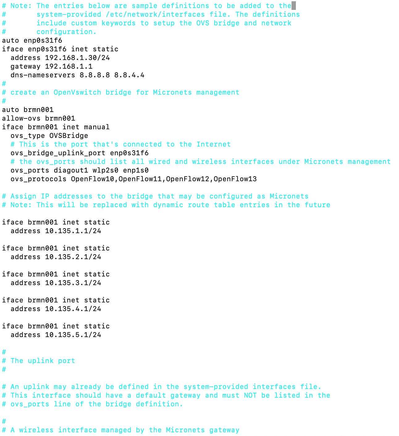
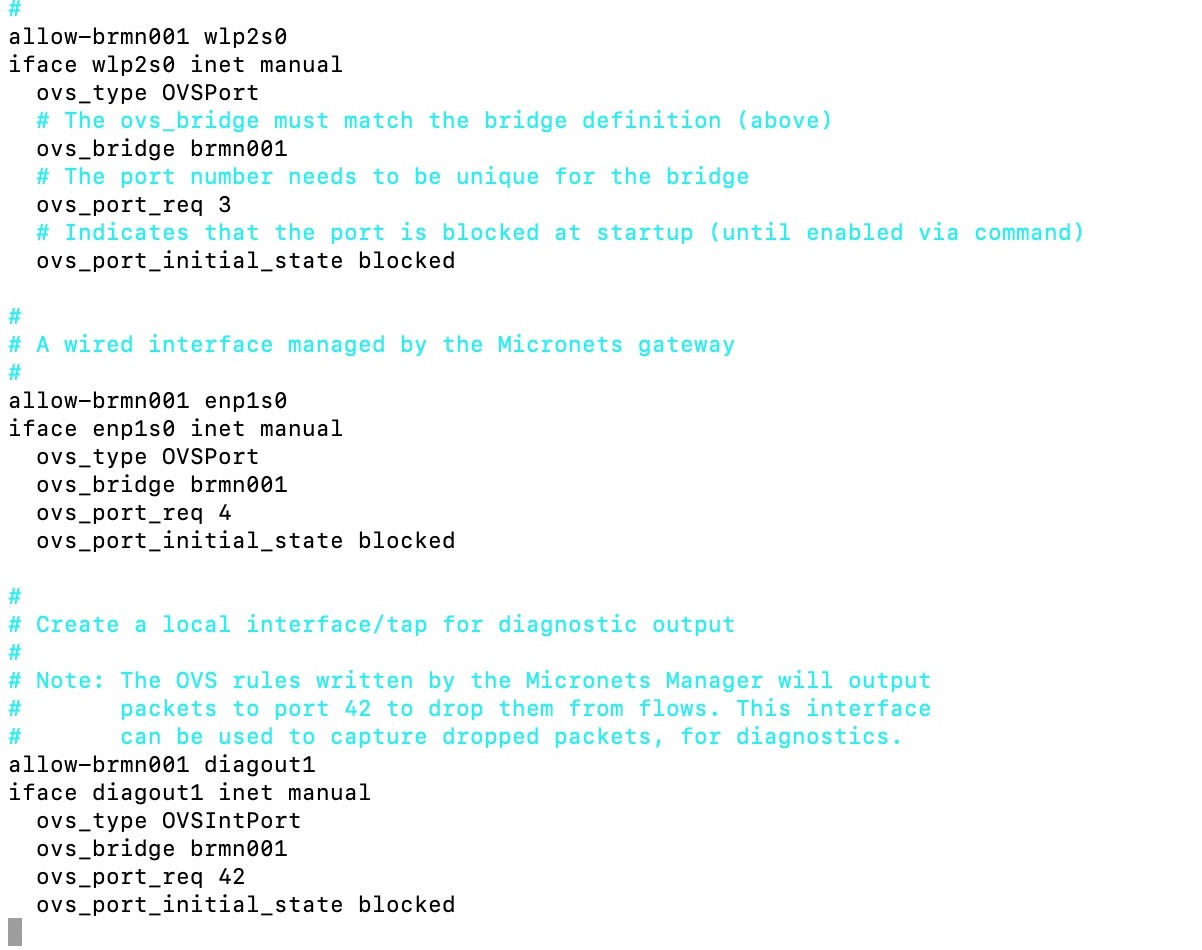
Create the gateway config file by entering the following command:
sudo vim gateway-config-001.jsonModify the following configuration to include your gateway’s MAC address and subnets as seen below, and copy them into the gateway-config-001.json file.
Be sure to modify the ipv4SubnetRanges definition to match the bridge subnet range—e.g., the file above defines five different subnets ranging from 10.135.1.1/24– 10.135.5.1/24, so we set octetC to have a minimum of 1 and a maximum of 5, and octetD to have a minimum of 2 and a maximum of 254, as seen in the config below:
{
    "version": "1.0",
    "gatewayId": "micronets-gw",
    "gatewayModel": "proto-gateway",
    "gatewayVersion": {"major":1, "minor":0, "micro":0},
    "configRevision": 1,
    "vlanRanges": [
        {"min":1000, "max":4095}
    ],
    "micronetInterfaces": [
        {
            "medium": "wifi",
            "name": "wlp2s0",
            "macAddress": "20:16:d8:2b:4b:41",
            "ssid": "micronets-gw",
            "dpp": {
                "supportedAkms": ["psk"]
            },
            "ipv4SubnetRanges": [
                {
                    "id": "range001",
                    "subnetRange": {"octetA": 10,
                        "octetB": 135,
                        "octetC": {"min":1, "max":5}
                    },
                    "subnetGateway": {"octetD": 1},
                    "deviceRange": {"octetD": {"min":2, "max":254}}
                }
            ]
        },
        {
            "medium": "ethernet",
            "name": "enp1s0",
            "macAddress": "80:ee:73:dc:64:1d",
            "ipv4Subnets": [
                {
                    "id": "range001",
                    "subnetRange": {"octetA": 10,
                        "octetB": 135,
                        "octetC": 250
                    },
                    "subnetGateway": {"octetD": 1},
                    "deviceRange": {"octetD": {"min":2, "max":254}}
                }
            ]
        }
    ]
}
Register a gateway configuration for a subscriber with the subscriber’s Micronets Manager instance by entering the following command (with the subscriber being subscriber-001 in this case):
curl -s -X POST https://nccoe-server1.micronets.net/sub/subscriber-001/api/mm/v1/micronets/odl \

-H "Content-Type: application/json" -d @./gateway-config-001.json | json_pp
You should see output similar to the following:
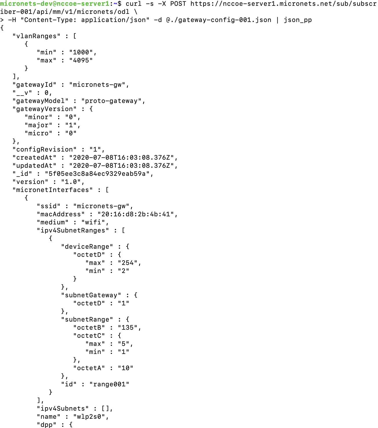
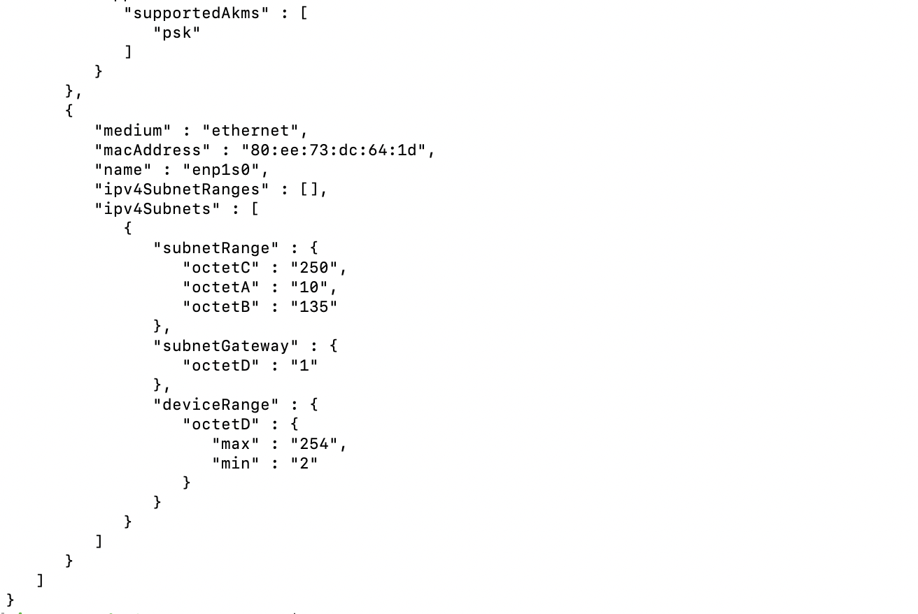
Confirm that the gateway ID is updated in the MSO portal by executing the following command:
curl -s https://nccoe-server1.micronets.net/micronets/mso-portal/portal/v1/subscriber/subscriber-001 | json_pp
You should see output similar to the following:
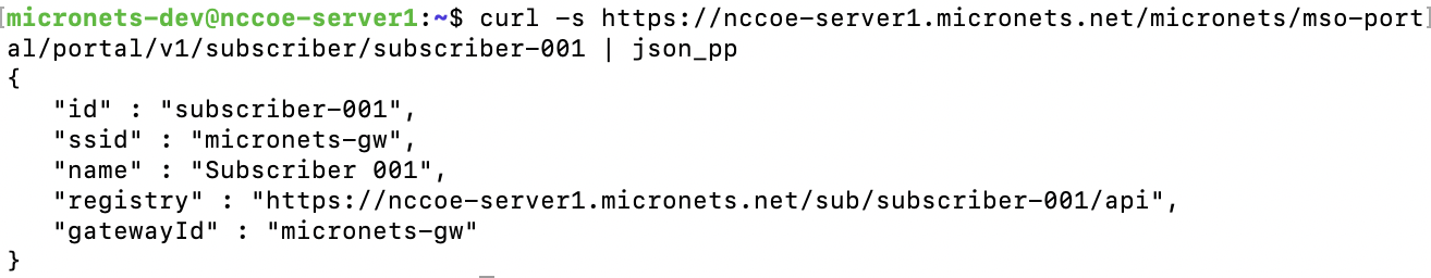
Configure the Micronets Gateway with the Websocket Proxy keys provisioned for the gateway:
Copy the client cert and key as well as the Websocket root certificate, created in the product installation section, from the cloud server into the gateway by executing the following commands from the gateway:
Copy the micronets-gw-service.pkeycert.pem to the gateway:
scp micronets-dev@nccoe-server1.micronets.net:Projects/micronets/micronets-gw-service.pkeycert.pem .
You should see the following output:

Copy the micronets-ws-root.cert.pem to the gateway:
scp micronets-dev@nccoe-server1.micronets.net:Projects/micronets/micronets-ws-root.cert.pem .
You should see the following output:

Copy them into the gateway service library to be loaded when the gateway is restarted:
sudo cp -v micronets-gw-service.pkeycert.pem micronets-ws-root.cert.pem /opt/micronets-gw/lib/
Change the Websocket lookup URL to use the MSO portal service on your server by completing the following commands:
Open the Micronets Gateway config file by executing the following command:
sudo vim /opt/micronets-gw/config.pyModify the WEBSOCKET_LOOKUP_URL and GATEWAY_ID to match the MSO portal Websocket lookup end point created in the product installation section and the Micronets Gateway ID:
WEBSOCKET_LOOKUP_URL = 'https://nccoe-server1.micronets.net/micronets/mso-portal/portal/v1/socket?gatewayId={gateway_id}'

GATEWAY_ID = 'micronets-gw'
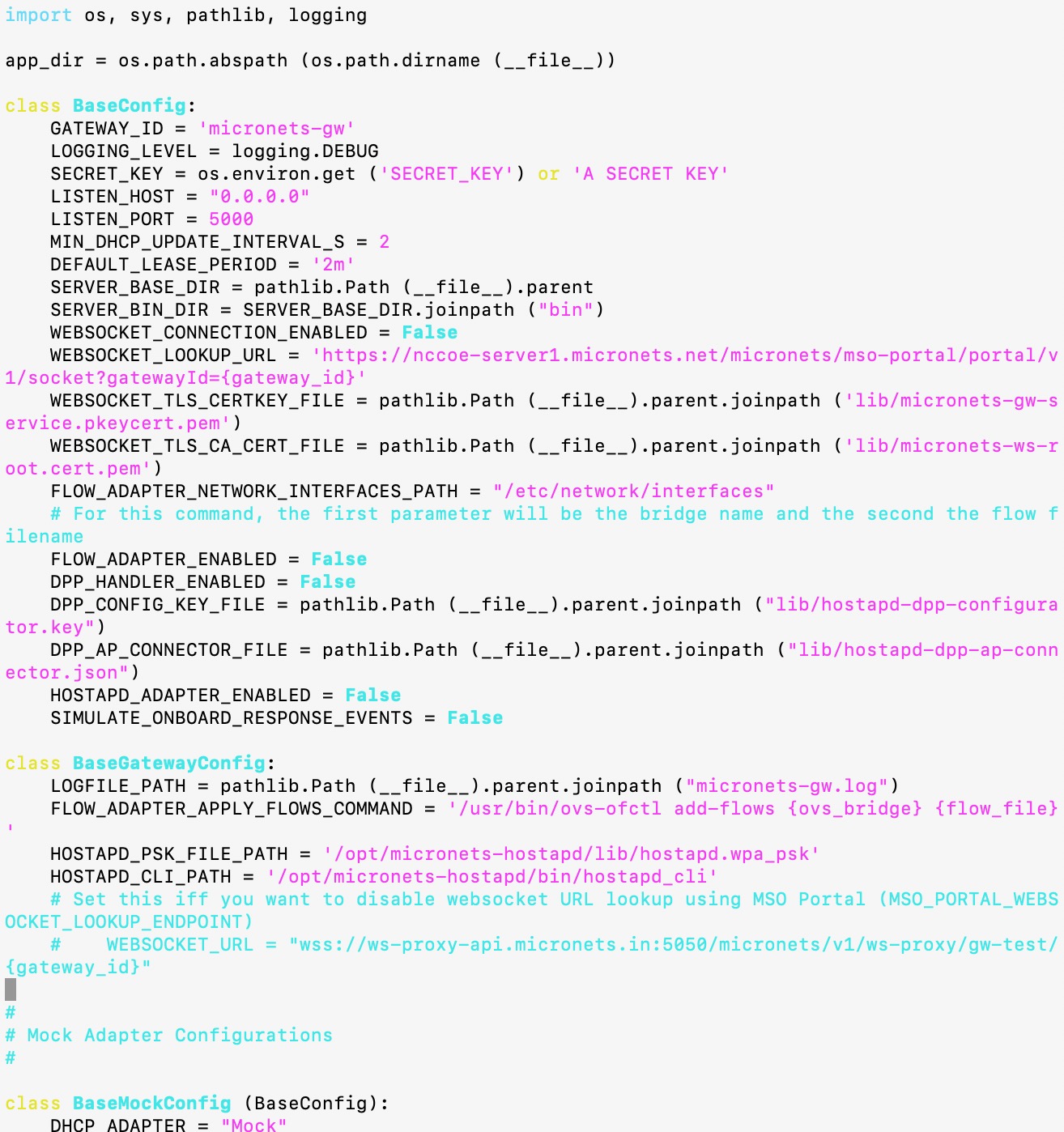
Restart the Micronets Gateway Service by executing the following command:
sudo systemctl restart micronets-gw.serviceCheck the Micronets Gateway Service log (/opt/micronets-gw/micronets-gw.log ) to verify that the gatewayʼs Websocket registration status was successful:
cat /opt/micronets-gw/micronets-gw.logYou should see output similar to the following:
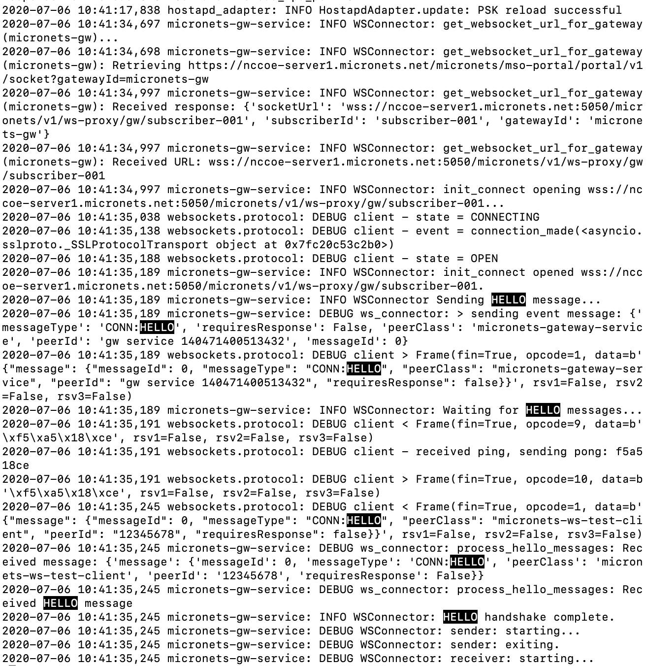
Confirm the establishment of the gateway-manager control connection by examining the Websocket Proxy connection reports in the Websocket Proxy log:
/etc/micronets/micronets-ws-proxy docker-logs | lessLook for the following in the log (with the MEETUP ID matching the subscriber name in question):
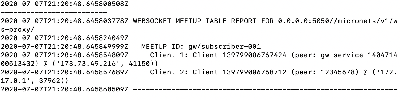
This indicates that the Micronets Gateway Service and the Micronets Manager for the subscriber connected and can exchange provisioning commands and event indications.
4.2.3 Integrating Micronets Proto-Pi Device
This section describes associating an MSO portal subscriber with the Micronets Gateway. For additional instructions not detailed in this documentation, please follow the link to the CableLabs documentation: https://github.com/cablelabs/micronets-pi3/blob/nccoe-build-3/README.md#Operation.
4.2.3.1 Prerequisites
To successfully complete this section, be sure to have completed the product installation section associated with the Micronets Proto-Pi device. Ensure all steps have been successfully completed before proceeding to the instructions.
4.2.3.2 Instructions
Connect to the Raspberry Pi via SSH by entering the following command:
ssh pi@192.168.30.191You will be prompted to enter the device password; the password will remain the same.
Change to the keys directory by entering the following command:
cd micronets-pi3/keys/Output the content of the proto-pi.dpp.pub file to copy the public key for this device. (Note: you will need to store this device key for registering the device with the MUD registry if doing so manually.)
cat proto-pi.dpp.pubHighlight and copy the key that was output by the previous command:
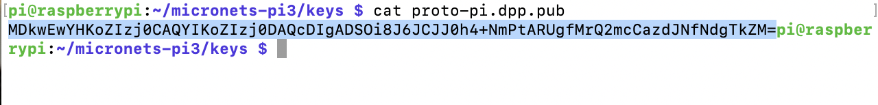
Modify the config.json file to include the key that was copied in the previous step, and modify the parameters of the file to match your setup:
sudo vim ~/micronets-pi3/config/config.jsonThe original file before editing should be similar to the following screenshot:
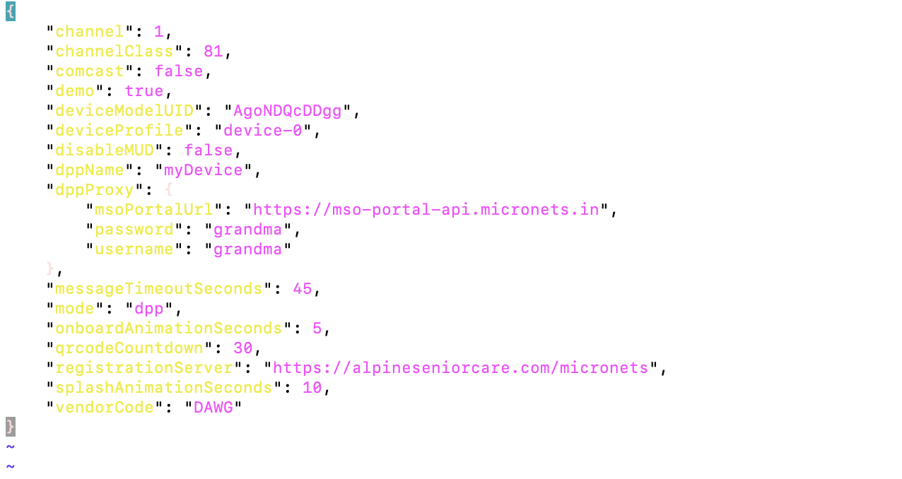
If doing manual device registration, edit the file to reflect the correct DeviceModelUID (should be the same name as the MUD file associated with this device), dppMUDUrl, msoPortalUrl, registrationServer, vendorCode as seen below:
{
    "channel": 1,
    "channelClass": 81,
    "comcast": false,
    "demo": true,
    "deviceModelUID": "nist-model-fe_northsouth.json",
    "deviceProfile": "device-0",
    "disableMUD": false,
    "dppMUDUrl": "https://nccoe-server1.microents.net/mud/v1/mud-url/TEST/MDkwEwYHKoZIzj0CAQYIKoZIzj0DAQcDIgACxjMF8Ucp6d3gRBImv78eGEMwB5igS2Kt5bnXI7VeBrc=",
    "dppName": "myDevice",
    "dppProxy": {
        "msoPortalUrl": "https://nccoe-server1.micronets.net/micronets/mso-portal/",
        "password": "grandma",
        "username": "grandma"
    },
    "messageTimeoutSeconds": 45,
    "mode": "dpp",
    "onboardAnimationSeconds": 5,
    "qrcodeCountdown": 30,
    "registrationServer": "https://nccoe-server1.micronets.net/registry/devices",
    "splashAnimationSeconds": 10,
    "vendorCode": "TEST"
}
If enabling self-registry, follow the steps described in this documentation: https://github.com/cablelabs/micronets-pi3/blob/nccoe-build-3/README.md#dpp-mode-mud-registry
Reboot the device for the new config file to take effect:
sudo reboot
4.2.4 Updating MUD Registry
This section describes the HTTP API operations for interacting with the MUD registry. The instructions detail how to register a MUD-capable device and its MUD URL with a vendor. For additional API operations not documented here, follow the link to the CableLabs MUD registry operation documentation: https://github.com/cablelabs/micronets-mud-registry/blob/nccoe-build-3/README.md#Operation.
4.2.4.1 Prerequisites
To successfully complete this section, be sure to have completed the product installation section.
4.2.4.2 Instructions
Retrieve the device registry URL for a vendor by entering the following curl command:
/mud/v1/device-registry/:vendor-code
curl -L https://nccoe-server1.micronets.net/mud/v1/device-registry/TESTYou should see output similar to the following:

Register a device with a vendor’s registry. This requires the device model UID and the public key, which can be modified and retrieved through the Micronets Proto-Pi:
/registry/devices/register-device/:device-model-UID64/:public-key
curl -X POST https://nccoe-server1.micronets.net/registry/devices/register-device/nist-model-fe_northsouth.json/MDkwEwYHKoZIzj0CAQYIKoZIzj0DAQcDIgADSOi8J6JCJJ0h4+NmPtARUgfMrQ2mcCazdJNfNdgTkZM=
You should see output similar to the following:
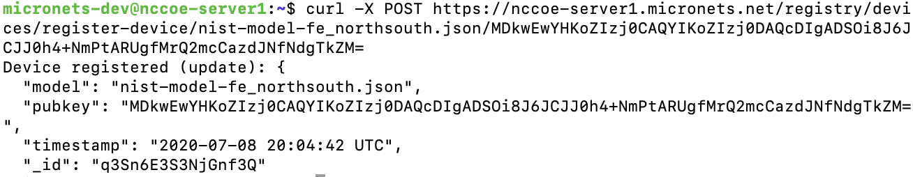
Retrieve the MUD registry URL for a vendor:
/mud/v1/mud-registry/:vendor-code
curl https://nccoe-server1.micronets.net/mud/v1/mud-registry/TESTYou should see output similar to the following:

Lookup a MUD URL from the vendor MUD registry:
/registry/devices/mud-registry/:public-key
curl https://nccoe-server1.micronets.net/registry/devices/mud-registry/MDkwEwYHKoZIzj0CAQYIKoZIzj0DAQcDIgADSOi8J6JCJJ0h4+NmPtARUgfMrQ2mcCazdJNfNdgTkZM=
You should see output similar to the following:

Delete a device from the MUD registry. (Note: if you do this step, the device will no longer be associated with a MUD file. Therefore, you should execute this command only if you do not intend to onboard the device with MUD capabilities.)
/registry/devices/remove-device/:public-key
curl -L -X POST https://nccoe-server1.micronets.net/registry/devices/remove-device/MDkwEwYHKoZIzj0CAQYIKoZIzj0DAQcDIgADSOi8J6JCJJ0h4+NmPtARUgfMrQ2mcCazdJNfNdgTkZM=
You should see output similar to the following:
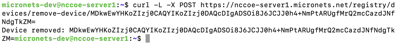
4.2.5 Integrating the Micronets iPhone App with MSO Portal
This section describes integrating the Micronets iPhone application with the MSO portal. For additional instructions not detailed in this documentation, please follow the link to the CableLabs documentation: https://github.com/cablelabs/micronets-mobile/blob/nccoe-build-3/README.md#Operation.
4.2.5.1 Prerequisites
A valid network connection on the iPhone is required as well as the completion of the product installation section related to the Micronets iPhone application.
4.2.5.2 Instructions
Open the Micronets mobile application:
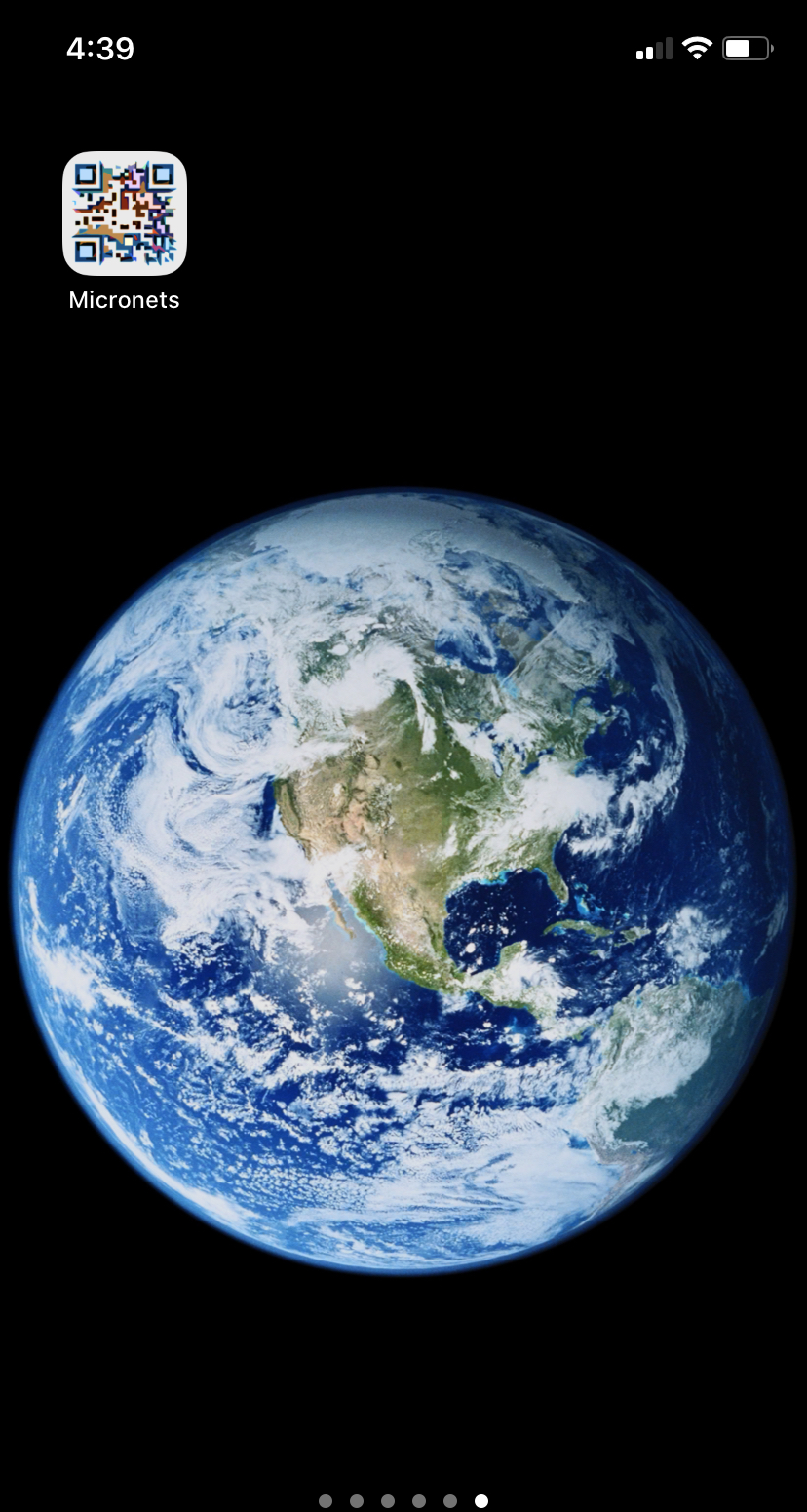
From the splash screen, click the gear button in the upper right corner to open the settings page:

Modify the following fields in the general settings:
Mode - DPP or Clinic: We select DPP; if you are selecting the Clinic mode, please follow the documentation for details related to the Clinic mode.
Debug - Leave this off, as CableLabs will be deprecating this in the future.
Enable MUD – If enabled, it will try to fetch the MUD file for the scanned device and prepopulate the Submit form prior to onboarding.
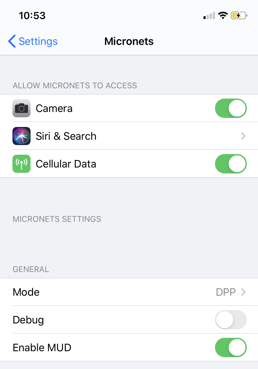
Modify the servers for the Micronets application:
DPP – MSO portal server URL for submitting onboard requests
IdOra – Server for user authentication. (Note: this is only required if utilizing the Clinic Mode.)
MUD – MUD registry server for looking up MUD files using the vendor code and public key in the QRCode. (Note: this only needs to be changed if you are deploying your own MUD registry.)
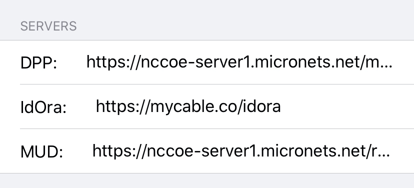
Back on the Micronets mobile application, enter your subscriber credentials and click SIGN IN:
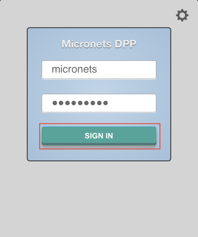
Click the READY TO SCAN button to open the camera for onboarding:
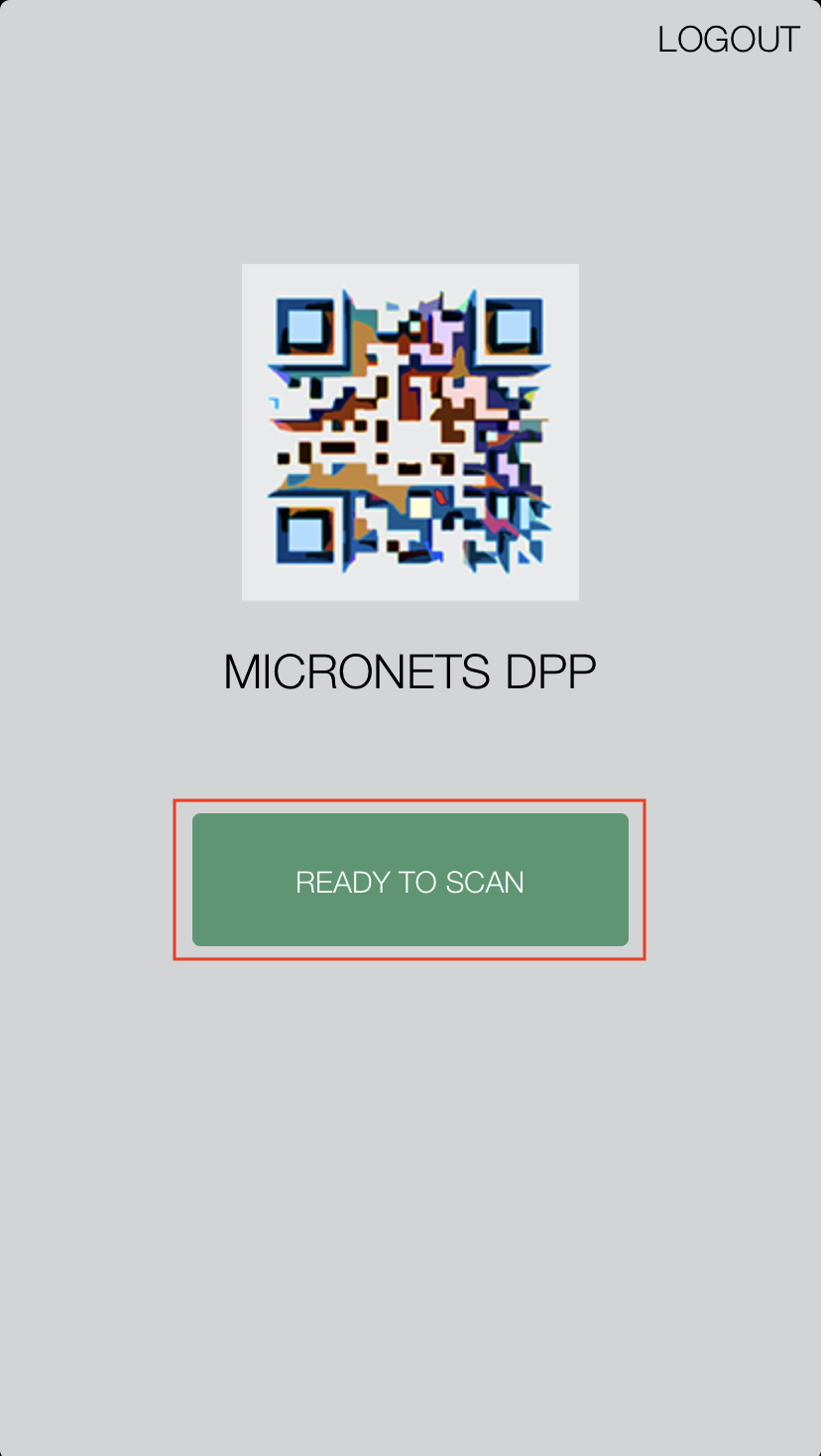
If prompted, allow the Micronets application camera access by clicking OK:
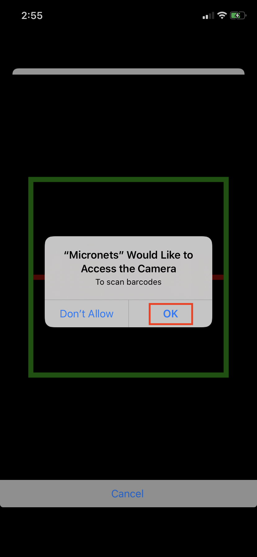
4.2.6 Onboarding Micronets Proto-Pi to a Micronet
This section describes how to onboard a configured Micronets Proto-Pi device to a micronet using the Micronet iPhone app. For additional instructions not detailed in this documentation, please follow the link to the CableLabs documentation: https://github.com/cablelabs/micronets-pi3/blob/nccoe-build-3/README.md#Operation.
4.2.6.1 Prerequisites
To successfully complete this section, the following is required:
a Raspberry Pi with the Micronets Proto-Pi software installed and configured
an iOS or Android phone with the Micronets application installed and configured
a Micronets subscriber account configured in Section 4.2.1
a gateway device associated with the Micronets subscriber configured in Section 4.2.2
4.2.6.2 Instructions
If leveraging the self-registration feature for MUD onboarding, ensure that an ethernet cable is connected to the Raspberry Pi running the Micronets Proto-Pi software.
Power on the Pi device. If leveraging the self-registration feature, the device will automatically be registered on first run.
On the mobile device, open the Micronets mobile application and log in with your subscriber credentials.
On the Mobile device, tap the Ready to Scan button:
On the Pi, click the Onboard icon:
You should see a QR code appear on the screen:
Scan the QRCode with the Micronet mobile application:
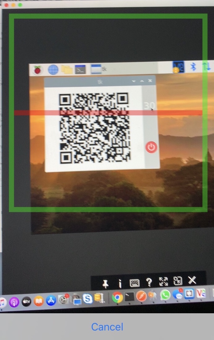
On the next screen that appears on the Micronets mobile application, input the following information in a timely fashion. (Note: these steps must be completed while the device is still in onboard mode.)
If a MUD file was found, the device CLASS and NAME will be pre-populated; modify as needed. In the case that a MUD file was not found, populate the CLASS and NAME manually.
Set the MODE to STA. (Note: the Mode should always be STA as of the time of this implementation.)
Tap the ONBOARD button to send the onboarding request to the MSO portal.
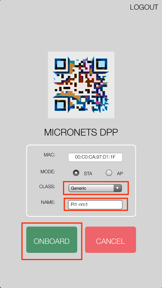
On the Pi, you will see the device has been onboarded to the Micronets Gateway and has received an IP address:
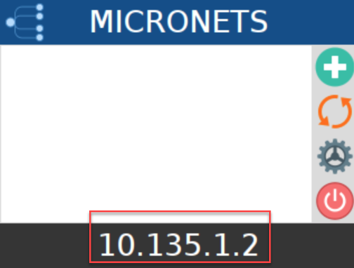
4.2.7 Interacting with Micronets Manager
The Micronets Manager, which is hosted in the cloud, has API endpoints exposed in order to allow implementers to manage the Micronets Gateway through the Micronets Manager service. This section describes how to set up postman and execute different functions.
4.2.7.1 Prerequisites
4.2.7.2 Instructions
Once Postman is installed and set up on the laptop, proceed to the following site to download the Micronets Manager Linode postman collections:
Follow the links:
Open the Postman application and sign in.
Click the import button to import the collections downloaded in step 1:
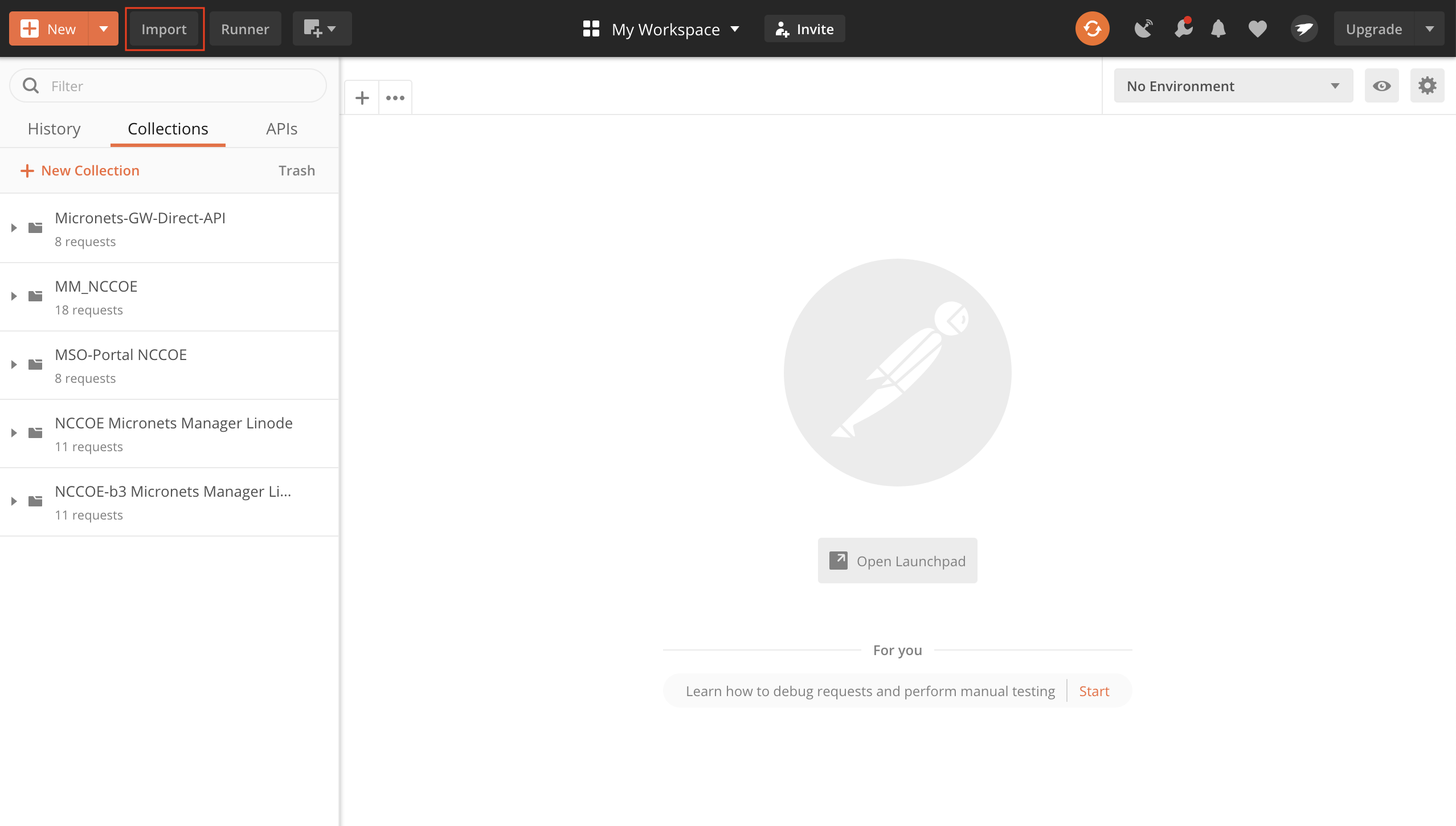
Next, click upload files:
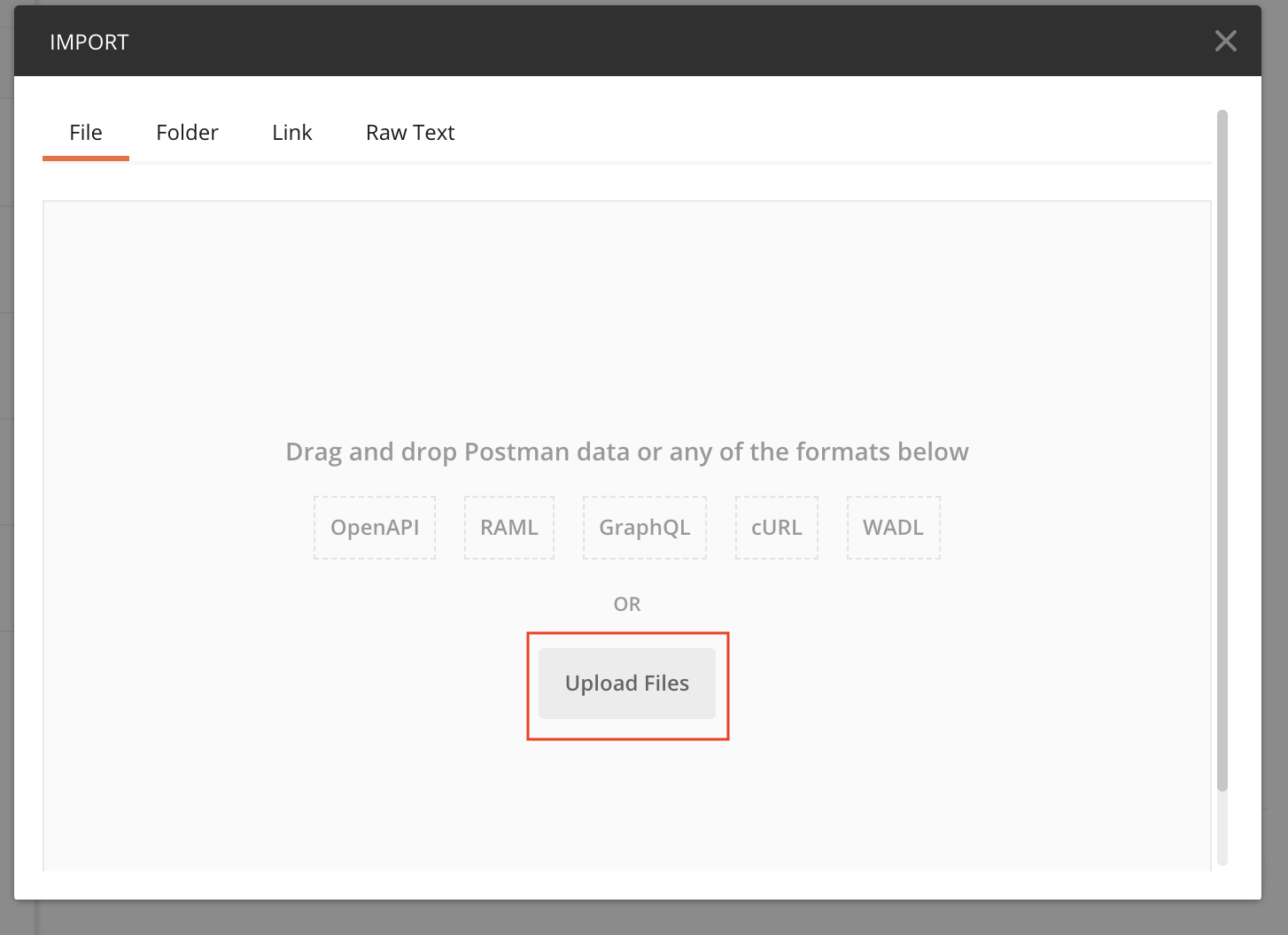
Select the Postman and global environmental variables collections downloaded in step 1:
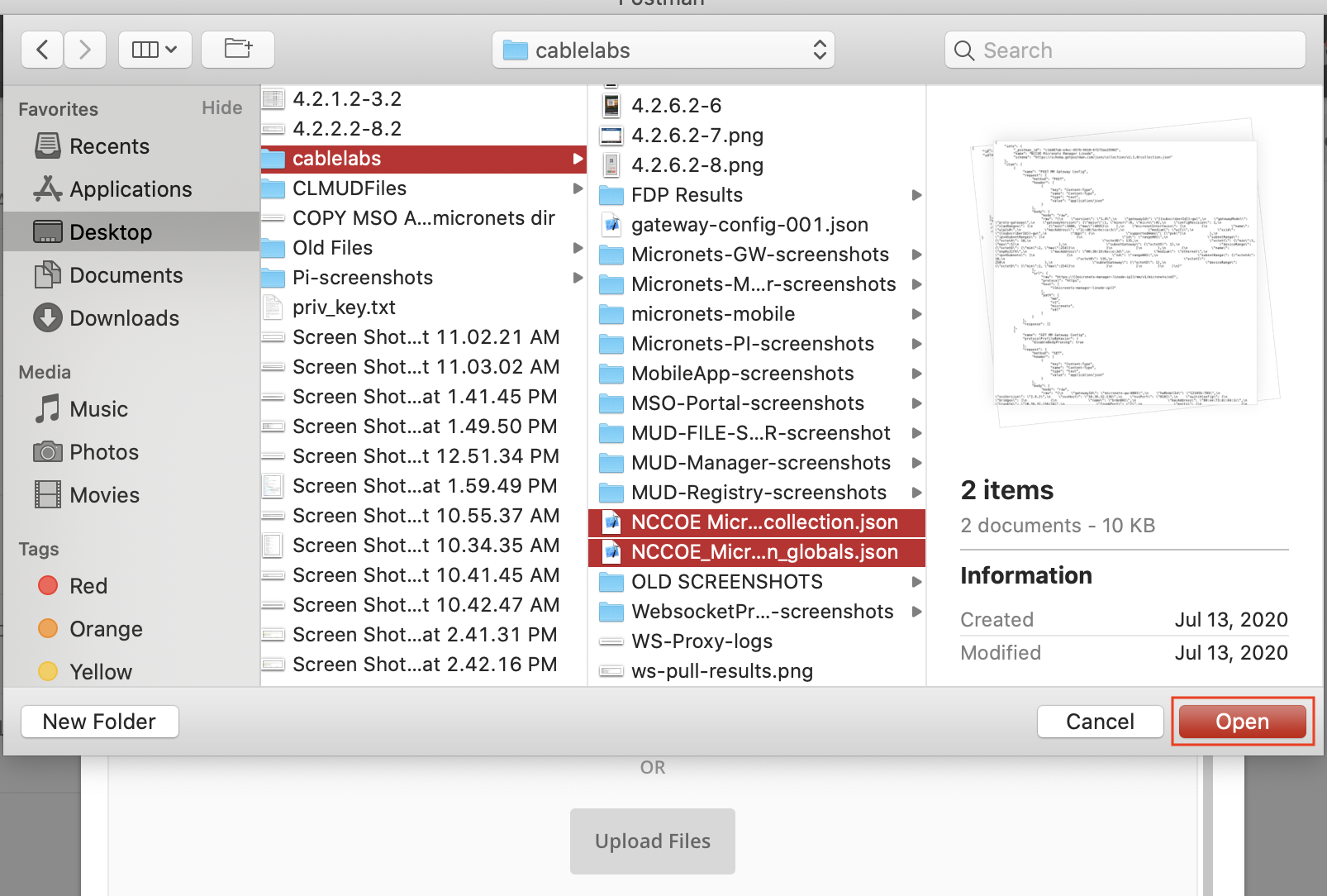
Confirm your import and click Import:
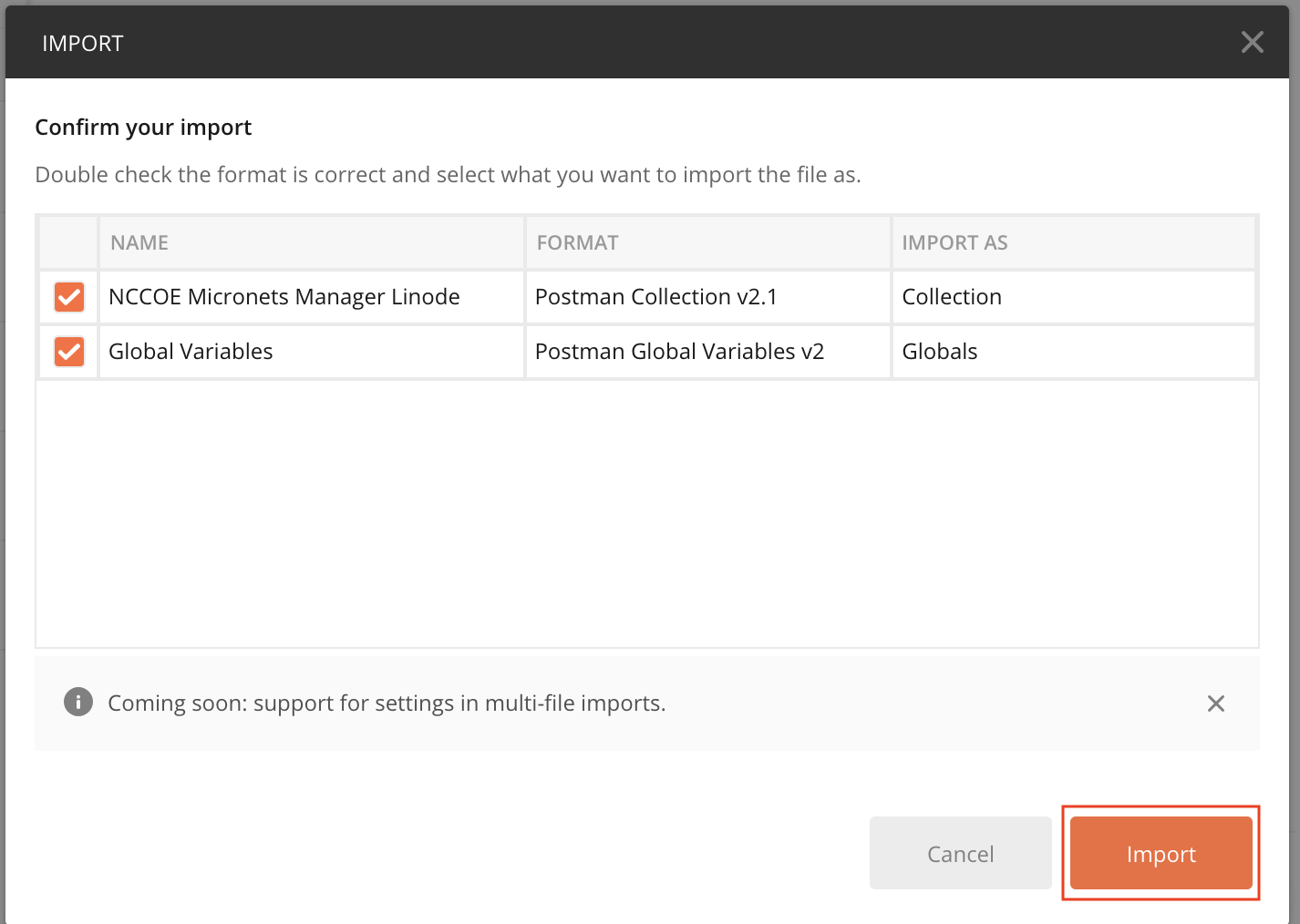
You will need to set the Globals for the micronets-manager-linode-ip, subscriberId, and mso-portal-linode-ip:
Click the gear button in the top right-hand corner of the application to Manage Environments:
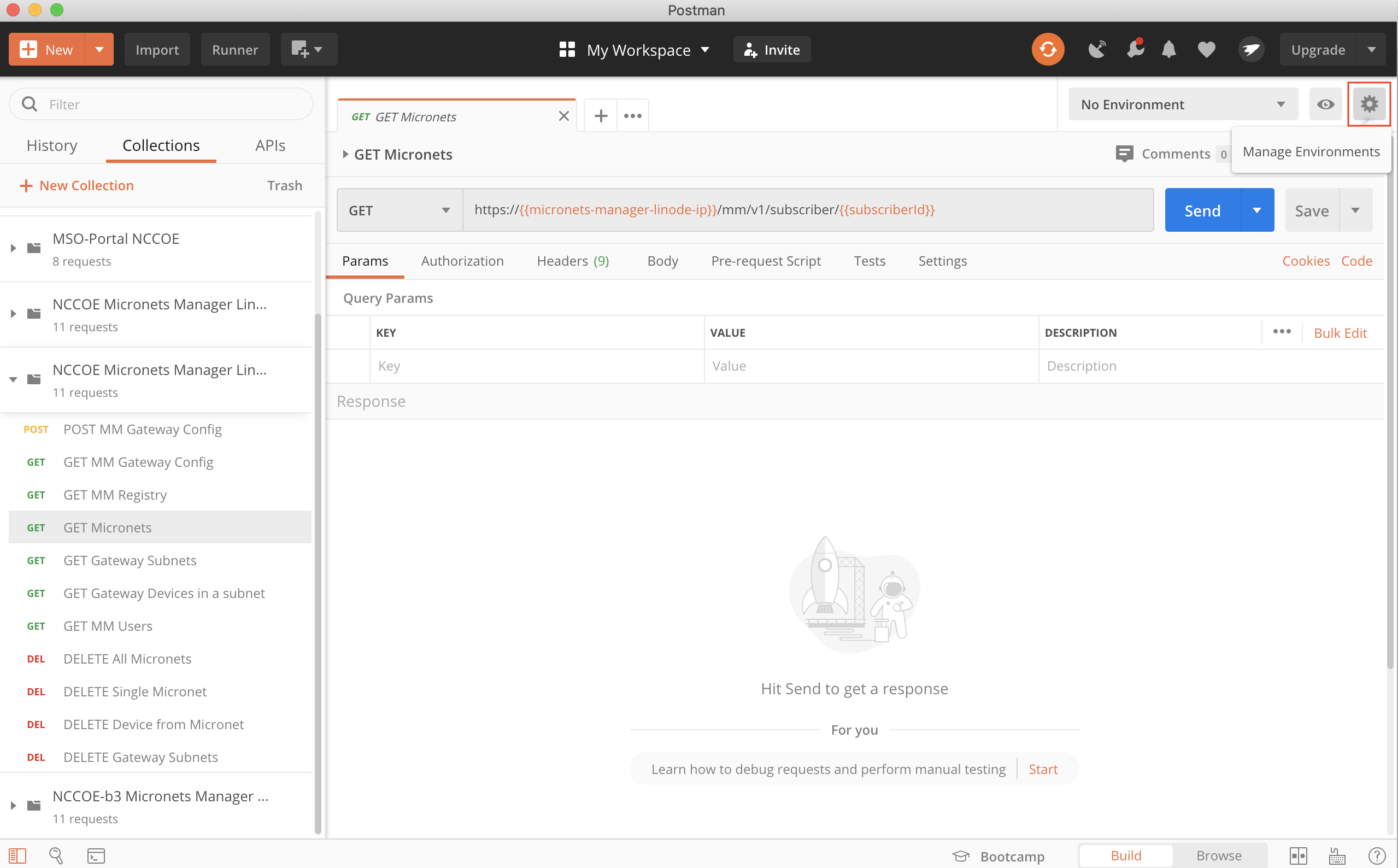
Click Globals:
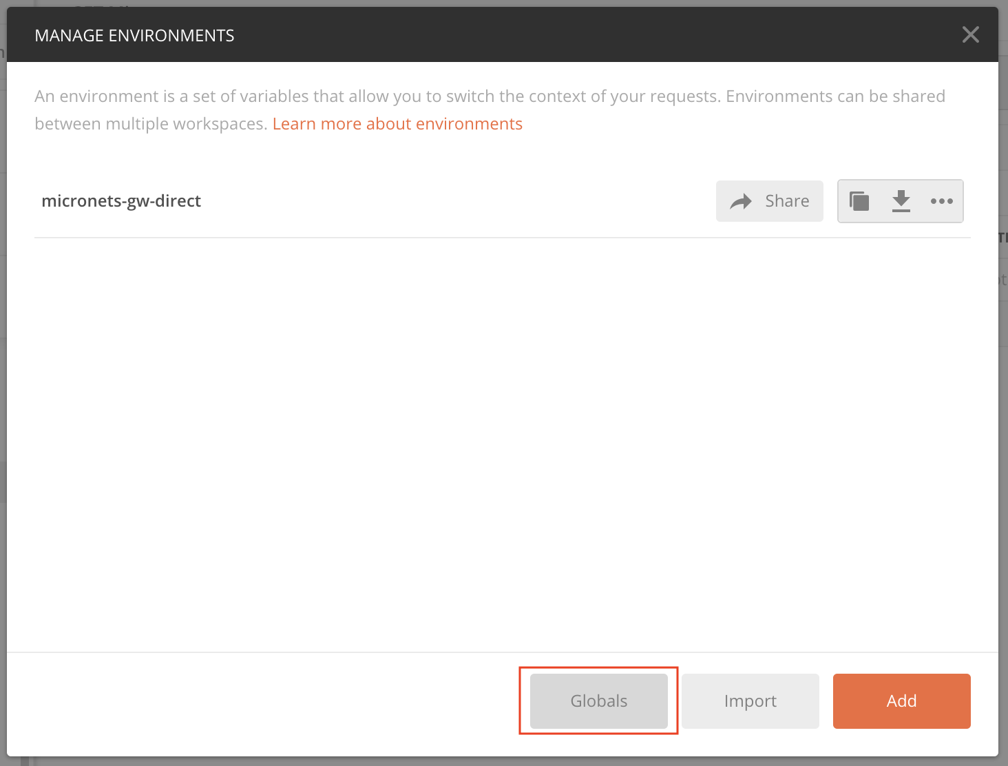
Modify the current values for the micronets-manager-linode-ip, subscriberId, and mso-portal-linode-ip variables as follows and click Save:
micronets-manager-linode-ip: nccoe-server1.micronets.net
subscriberId: subscriber-001
mso-portal-linode-ip: nccoe-server1.micronets.net
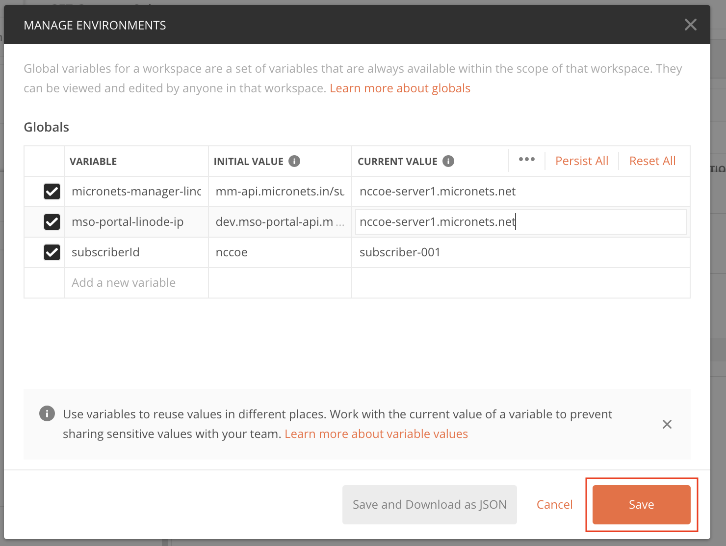
Exit out of the menu:
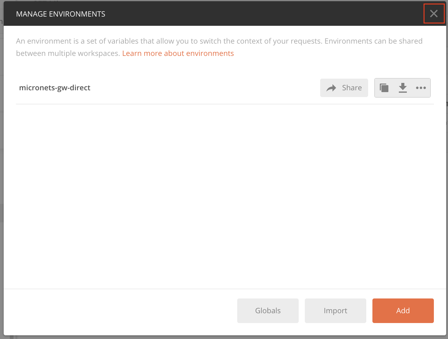
Next, open the Postman collection and review and modify the URLs for the calls to ensure the API endpoint paths match your implementation:
Modify the GET MM Gateway Config command to reflect the following. Executing this command will pull the current Gateway config from the Micronets Manager:
http://{{micronets-manager-linode-ip}}/mm/v1/micronets/odl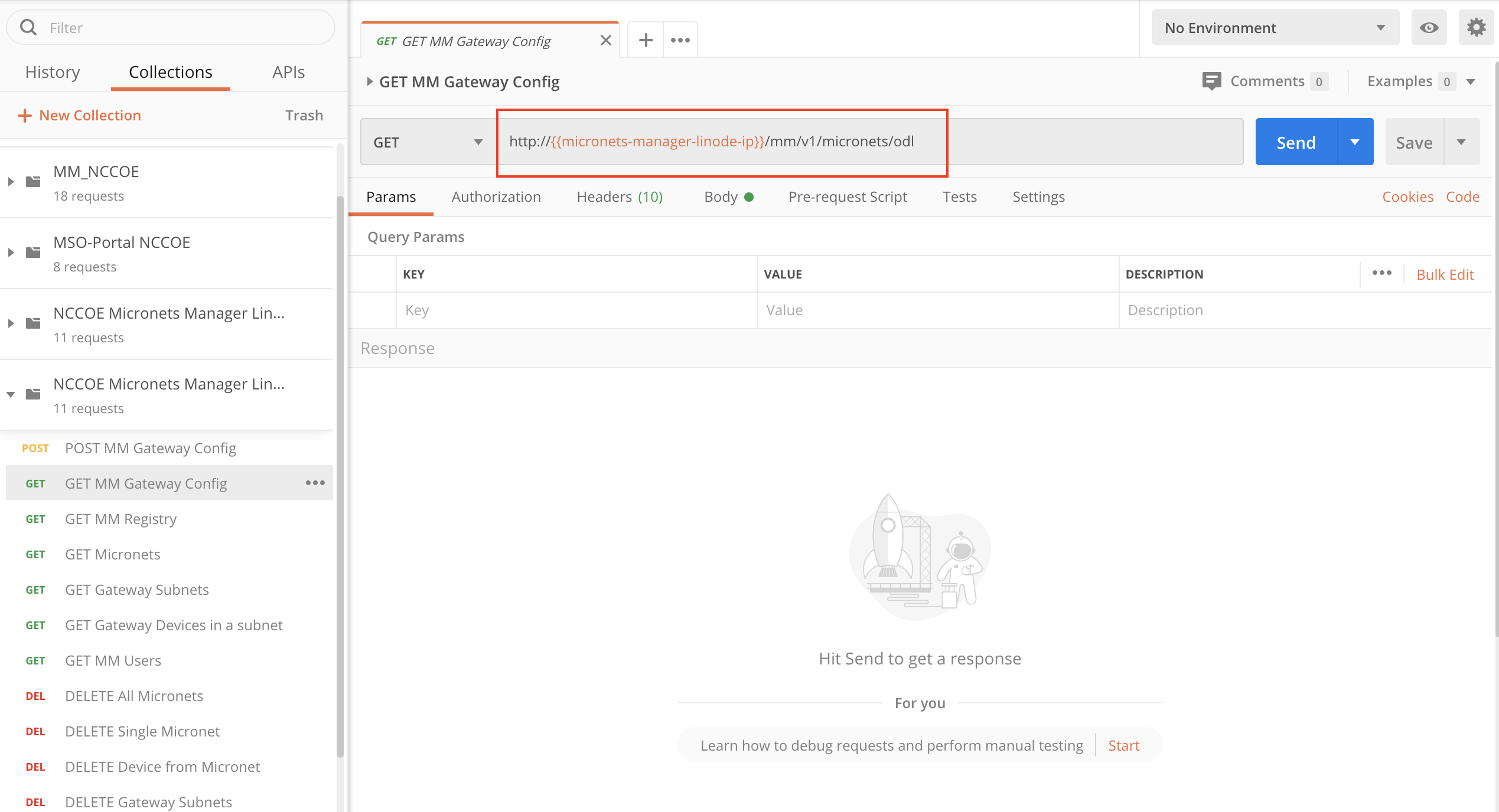
Modify the GET MM Registry command to reflect the following. Executing this command will pull the current registry from the Micronets Manager:
https://{{micronets-manager-linode-ip}}/mm/v1/micronets/registry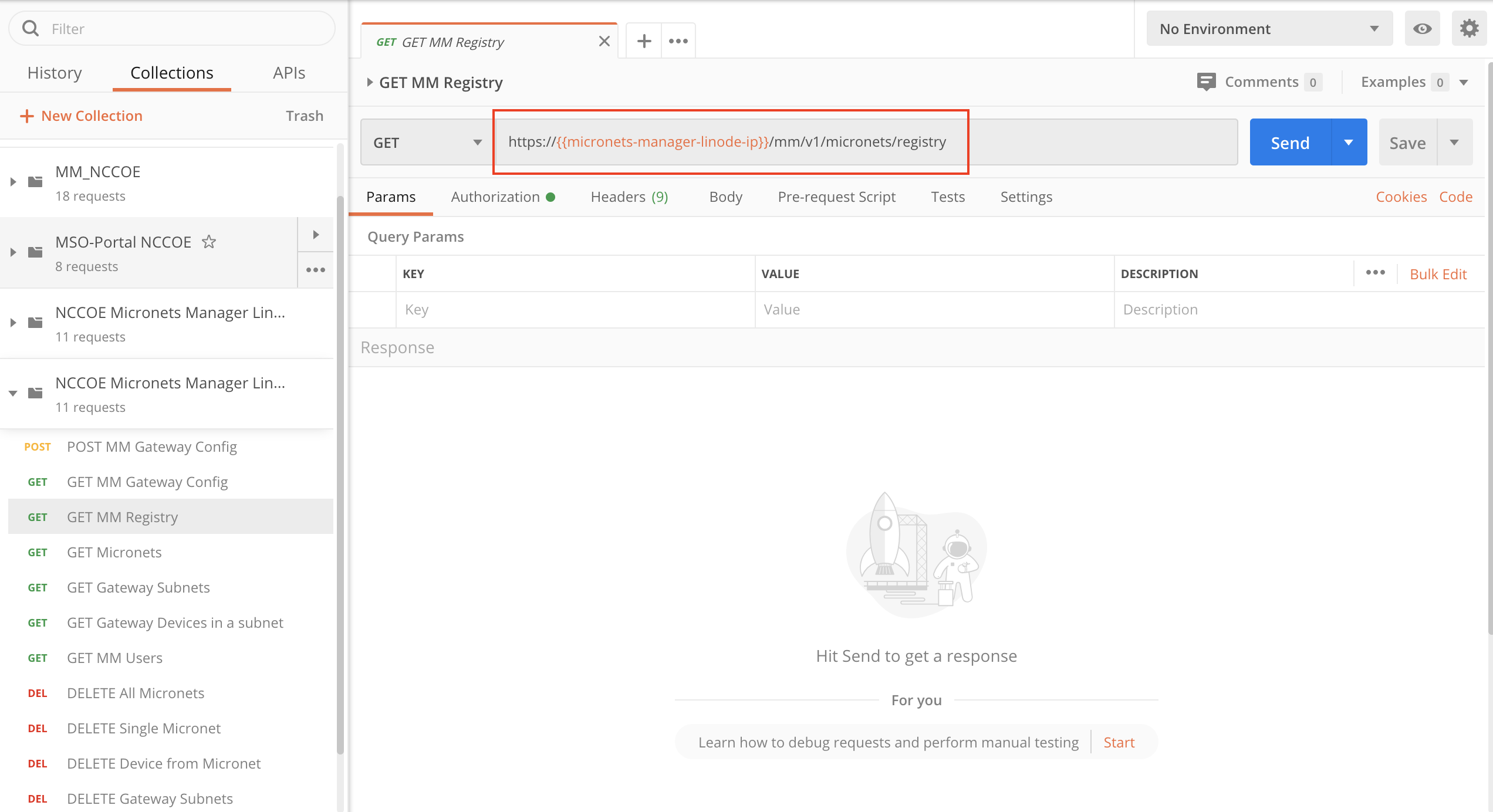
Modify the GET Micronets command to reflect the following. Executing this command will pull a list of the current micronets on the Gateway from the Micronets Manager:
https://{{micronets-manager-linode-ip}}/sub/{{subscriberId}}/api/mm/v1/subscriber/{{subscriberId}}
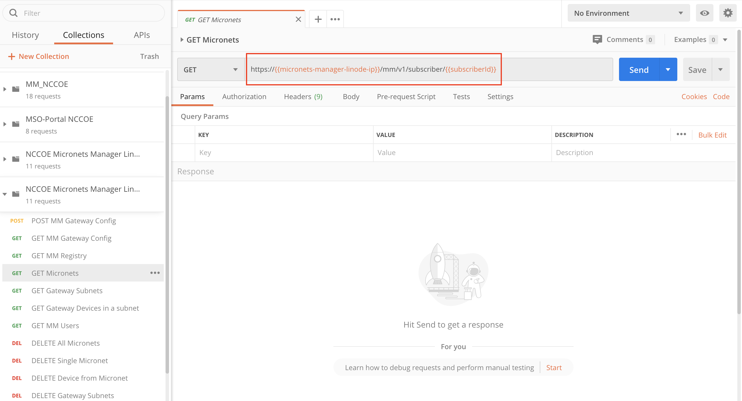
Modify the GET Gateway Subnets command to reflect the following. Executing this command will pull a list of the current subnets on the Gateway from the Micronets Manager:
https://{{micronets-manager-linode-ip}}/sub/{{subscriberId}}/api/mm/v1/dhcp/subnets
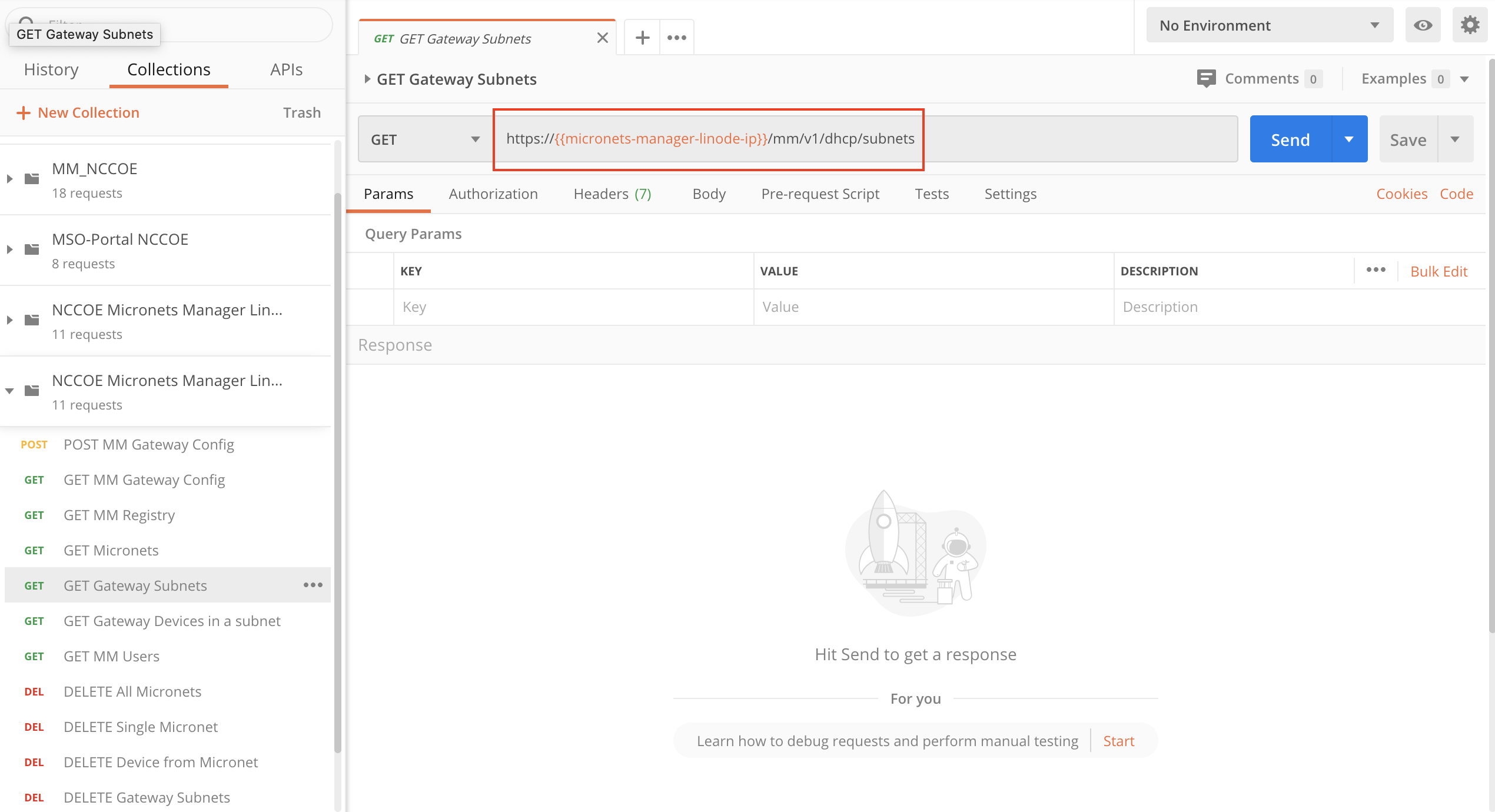
Modify the GET Gateway Devices in a subnet command to reflect the following. Executing this command will pull a list of the current devices in a subnet on the Gateway from the Micronets Manager:
https://{{micronets-manager-linode-ip}}/sub/{{subscriberId}}/api/mm/v1/dhcp/subnets/subnetId/devices
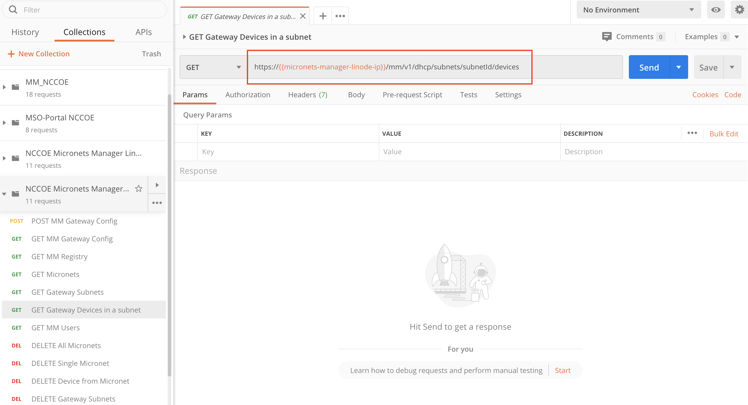
Modify the GET MM Users command to reflect the following. Executing this command will pull a list of the users associated with the subscriber ID from the Micronets Manager:
https://{{micronets-manager-linode-ip}}/sub/{{subscriberId}}/api/mm/v1/micronets/users
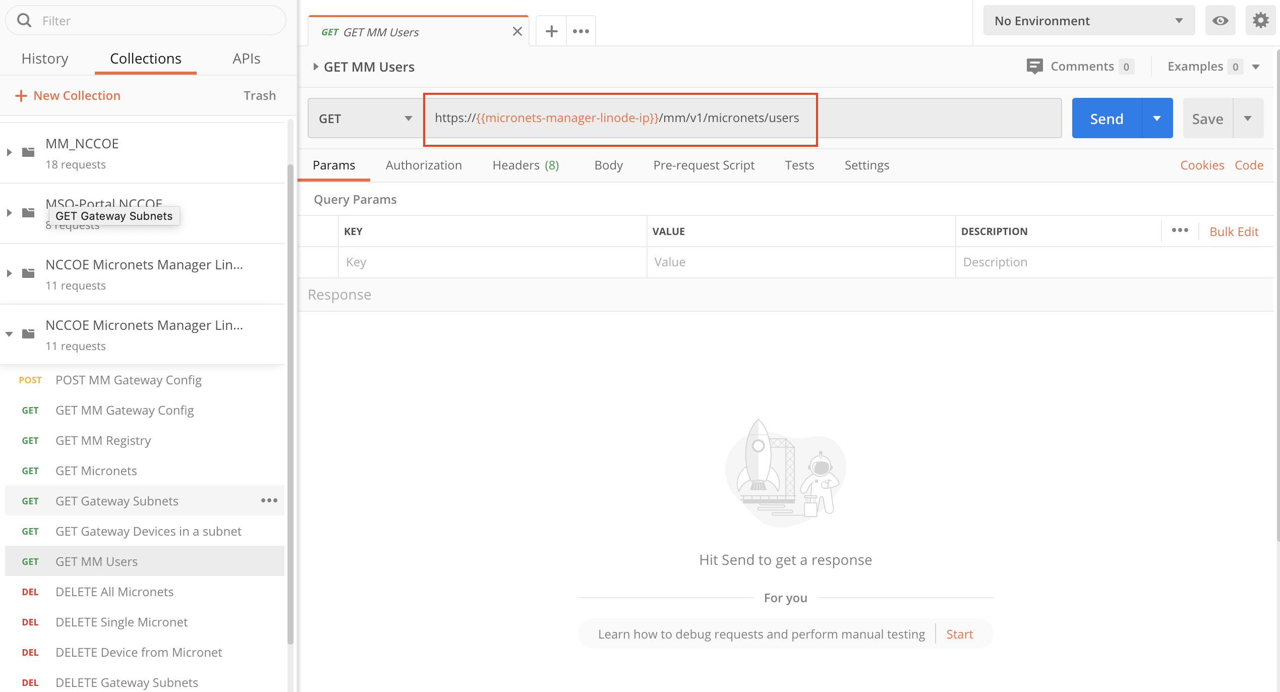
Modify the DELETE All Micronets command to reflect the following. Executing this command will delete all of the current micronets on the Gateway via the Micronets Manager:
https://{{micronets-manager-linode-ip}}/sub/{{subscriberId}}/api/mm/v1/subscriber/{{subscriberId}}/micronets
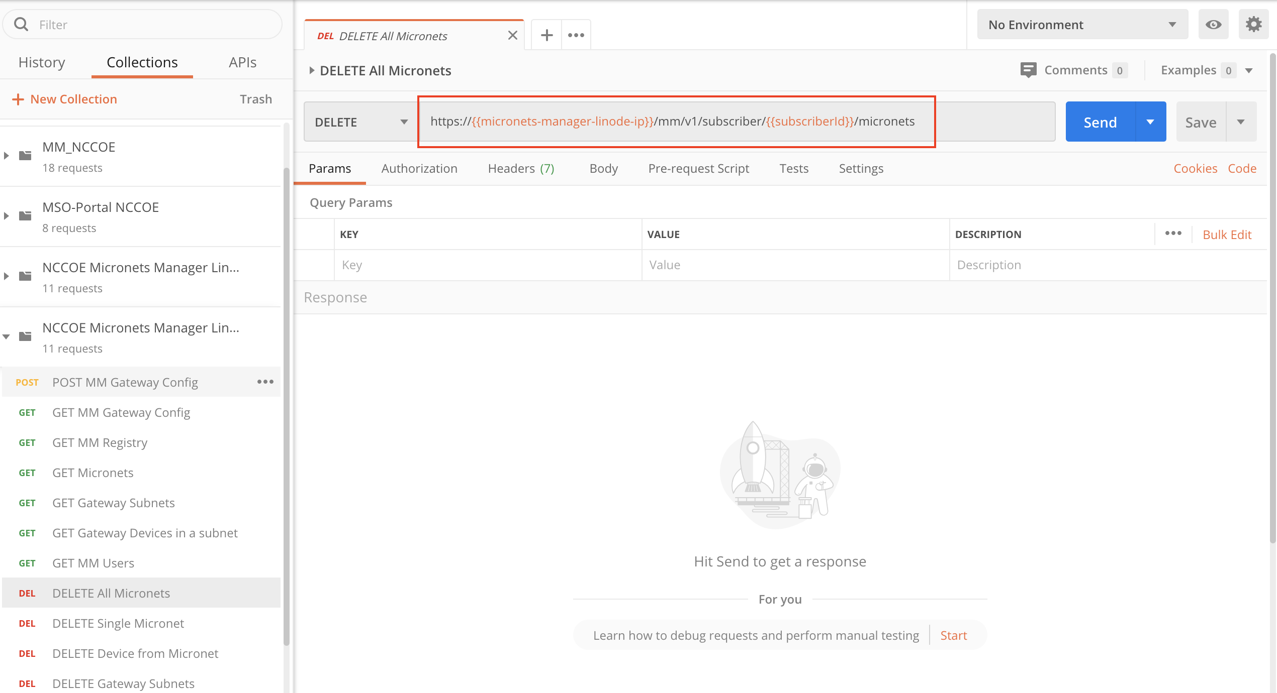
Modify the DELETE Single Micronets command to reflect the following. Executing this command will delete a specific micronet on the Gateway via the Micronets Manager. This command is to be modified before executing to specify the <micronetID>, which can be retrieved by executing the GET Micronets command:
https://{{micronets-manager-linode-ip}}/sub/{{subscriberId}}/api/mm/v1/subscriber/{{subscriberId}}/micronets/<micronetID>
Below is an example of this command:
https://{{micronets-manager-linode-ip}}/sub/{{subscriberId}}/api/mm/v1/subscriber/{{subscriberId}}/micronets/2453819029
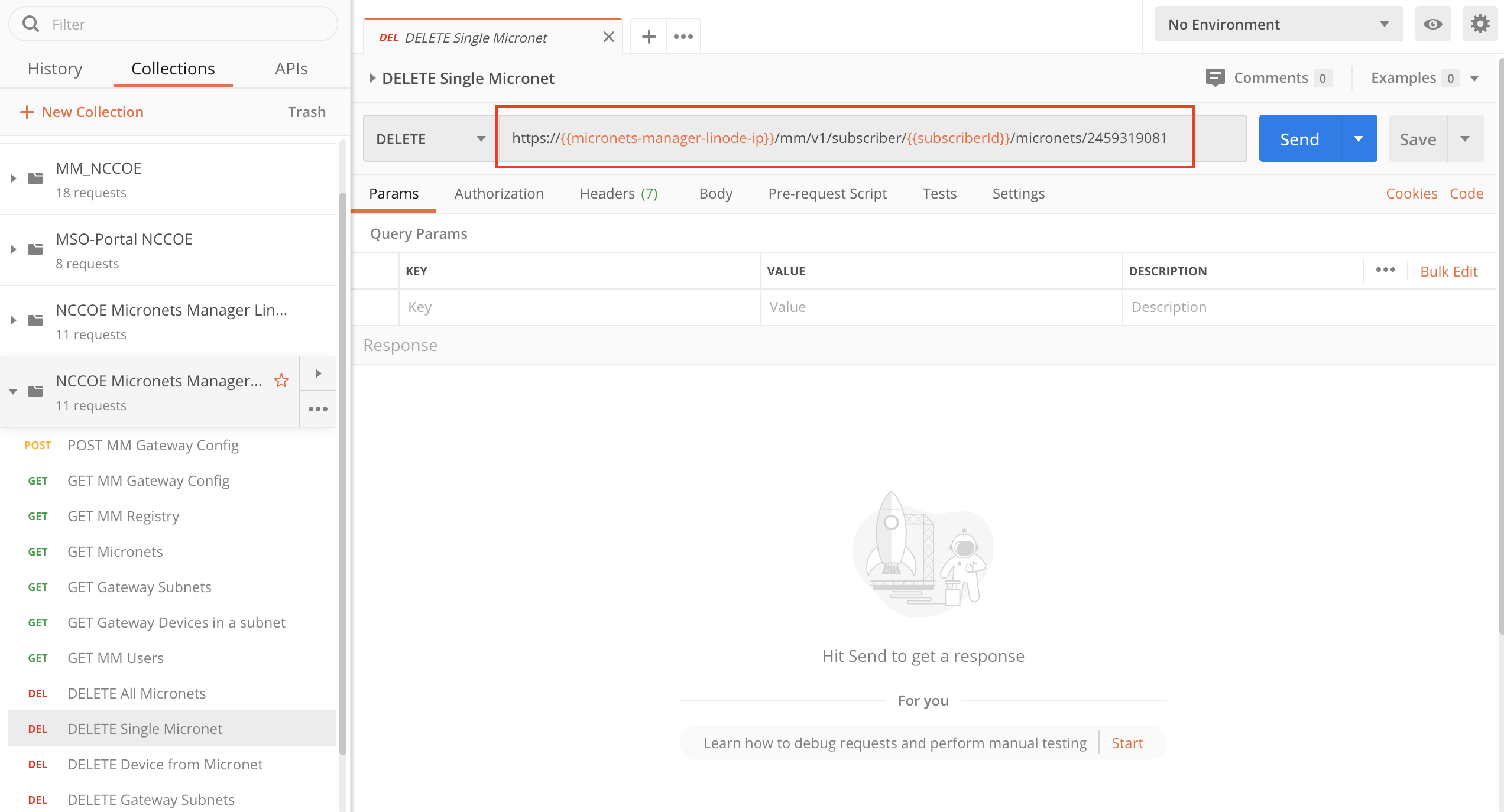
Modify the DELETE Device from Micronet command to reflect the following. Executing this command will delete a specific device from a particular micronet on the Gateway via the Micronets Manager. This command is to be modified before executing to specify the <micronetID> and <deviceID>, which can be retrieved by executing the GET Micronets command:
https://{{micronets-manager-linode-ip}}/sub/{{subscriberId}}/api/mm/v1/subscriber/{{subscriberId}}/micronets/<micronetID> /devices/<deviceID>
Below is an example of this command:
https://{{micronets-manager-linode-ip}}/sub/{{subscriberId}}/api/mm/v1/subscriber/{{subscriberId}}/micronets/2136369149/devices/da34c7219c2c97f0e2c2838e66c725d137f3c097
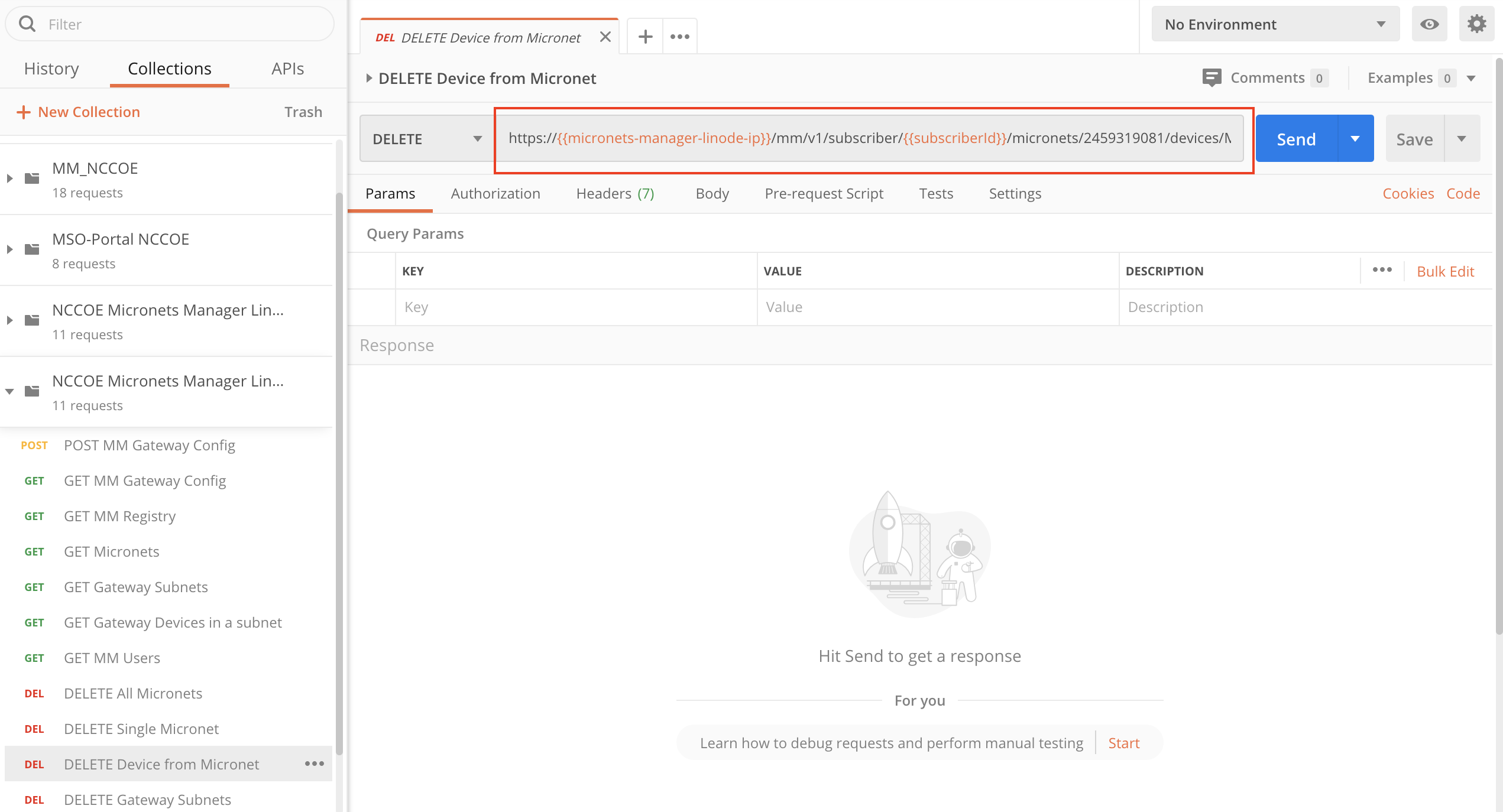
Modify the DELETE Gateway Subnets command to reflect the following. Executing this command will delete all subnets on the Gateway via the Micronets Manager:
https://{{micronets-manager-linode-ip}}/sub/{{subscriberId}}/api/mm/v1/dhcp/subnets
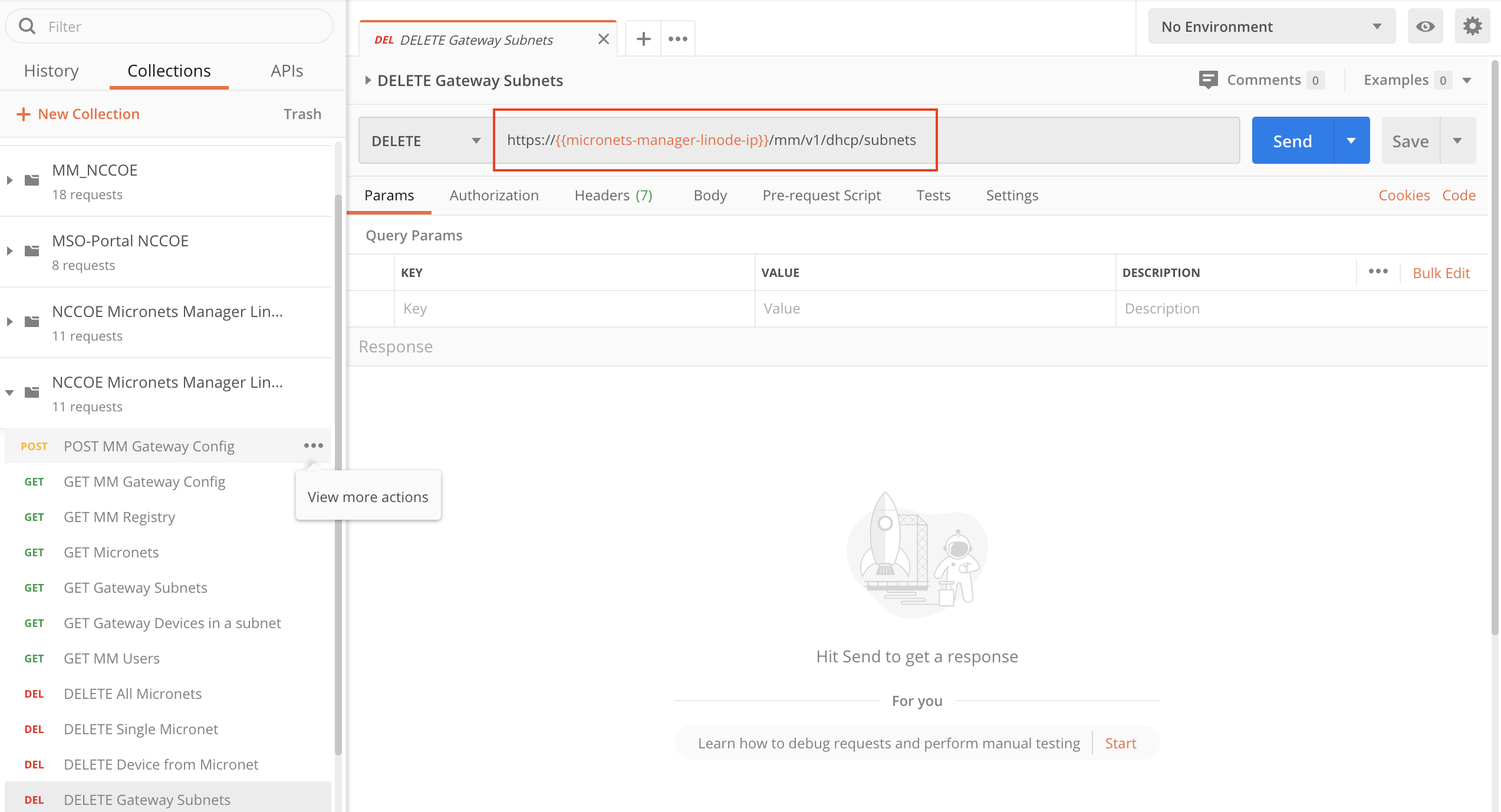
4.2.8 Removing Micronets Proto-Pi from a Micronet
Removing a Micronets Proto-Pi from a micronet will remove the network credentials from the device. For additional instructions not detailed in this documentation, please follow the link to the CableLabs documentation: https://github.com/cablelabs/micronets/blob/nccoe-build-3/docs/operation/pi-offboarding.md.
4.2.8.1 Prerequisites
To successfully complete this section, the following are required:
a Raspberry Pi with the Micronets Proto-Pi software installed and configured
a device that is currently onboarded to the Micronets Gateway
4.2.8.2 Instructions
Power on the Micronets Proto-Pi device.
Tap Settings:
Tap Reset:
You should see output similar to the following:
4.2.9 Removing an MSO Subscriber
Removing a subscriber involves removing the subscriber from the MSO portal database, removing the subscriber’s micronets, and removing the subscriberʼs Micronets Manager. For additional instructions not detailed in this documentation, please follow the link to the CableLabs documentation: https://github.com/cablelabs/micronets/blob/nccoe-build-3/docs/operation/pi-offboarding.md.
4.2.9.1 Prerequisites
To successfully complete this section, be sure to have first completed both the product installation section and the section that details adding the MSO portal.
4.2.9.2 Instructions
Remove the subscriber from the MSO portal:
curl -s -X DELETE https://nccoe-server1.micronets.net/micronets/mso-portal/portal/v1/subscriber/subscriber-001 | json_pp
Verify that the subscriber is removed from the MSO portal by executing the following commands:
Check if the subscriber ID is present in the subscriber list:
curl -s https://nccoe-server1.micronets.net/micronets/mso-portal/portal/v1/subscriber/subscriber-001 | json_pp
You should see output similar to the following:

Next, check if the user is present in the list of users in the MSO portal:
curl -s https://nccoe-server1.micronets.net/micronets/mso-portal/portal/v1/users | json_pp
You should see output similar to the following:
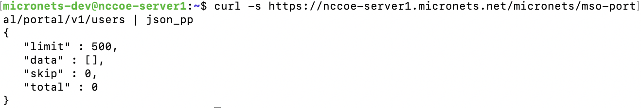
Finally, check to see if there is a socket present for the subscriber ID:
curl -s https://nccoe-server1.micronets.net/micronets/mso-portal/portal/v1/socket/subscriber-001 | json_pp
You should see output similar to the following:
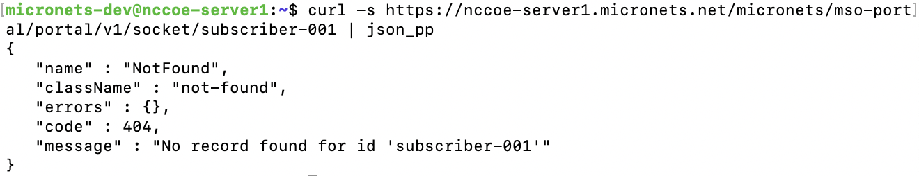
Note: There could be scenarios where the commands above do not show empty lists. If that is the case, the subscriber has not been deleted properly. You can delete the subscriber entries in the MSO portal subtables by executing the following commands:
Delete the subscriber ID from the user list manually:
curl -s -X DELETE https://nccoe-server1.micronets.net/micronets/mso-portal/portal/v1/users/subscriber-001 | json_ppDelete the subscriber ID from the socket list manually:
curl -s -X DELETE https://nccoe-server1.micronets.net/micronets/mso-portal/portal/v1/socket/subscriber-001
Remove all the micronets for the subscriber using:
curl -s -X DELETE https://nccoe-server1.micronets.net/sub/subscriber-001/api/mm/v1/subscriber/subscriber-001/micronets
You should see output similar to the following:
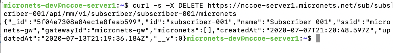
This will remove the micronets on the connected Micronets Gateway. If the gateway is not connected to its peer Micronets Manager, the micronets can be deleted directly on the gateway using:
curl -s -X DELETE http://localhost:5000/micronets/v1/gateway/micronetsYou can verify that the micronets have been deleted by running:
curl -s https://nccoe-server1.micronets.net/sub/subscriber-001/api/mm/v1/subscriber/subscriber-001/micronets
This should return an empty micronets list.
Remove the Micronets Manager docker container for a subscriber by running:
/etc/micronets/micronets-manager.d/mm-container delete subscriber-001You will be prompted to remove the config file:
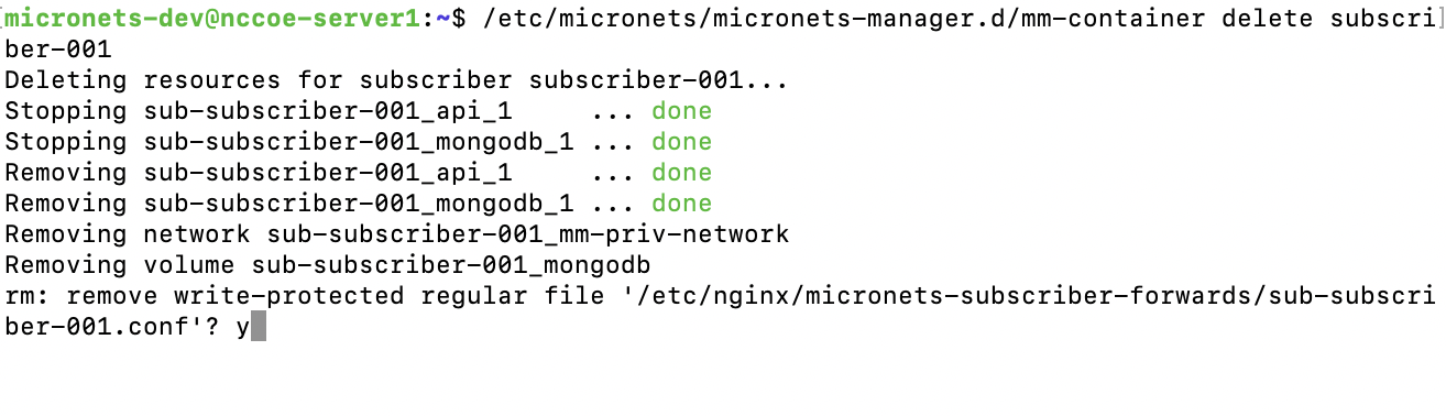
Lastly, you will be prompted to provide sudo privileges:
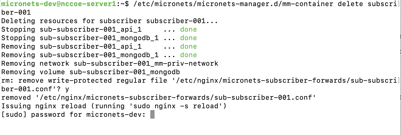
Confirm the Micronets Manager for the subscriber is removed by executing the following command:
curl -s https://nccoe-server1.micronets.net/sub/subscriber-001/api/mm/v1/subscriber/subscriber-001
5 Build 4 Product Installation Guides
This section of the practice guide contains detailed instructions for installing and configuring the products used to implement Build 4. For additional details on Build 4’s logical and physical architectures, please refer to NIST SP 1800-15B.
5.1 NIST SDN Controller/MUD Manager
5.1.1 NIST SDN Controller/MUD Manager Overview
This is a limited implementation that is intended to introduce a MUD manager build on top of an SDN controller. Build 4 implements all the abstractions in the MUD specification. At testing, this build uses strictly IPv4, and DHCP is the only standardized mechanism that it supports to associate MUD URLs with devices.
Build 4 uses a MUD manager built on the OpenDaylight SDN controller. This build works with IoT devices that emit their MUD URLs through DHCP. The MUD manager works by snooping the traffic passing through the controller to detect the emission of a MUD URL. The MUD URL extracted by the MUD manager is then used to retrieve the MUD file and corresponding signature file associated with the MUD URL. The signature file is used to verify the legitimacy of the MUD file. The MUD manager then translates the access control entries in the MUD file into flow rules that are pushed to the switch.
5.1.2 Configuration Overview
The following subsections document the software, hardware, and network configurations for the Build 4 SDN controller/MUD manager.
5.1.2.1 Hardware Configuration
This build requires installing the SDN controller/MUD manager on a server with at least two gigabytes of random access memory. This server must connect to at least one SDN-capable switch or router on the network, which is the MUD policy enforcement point. The MUD manager works with any OpenFlow 1.3-enabled SDN switch. For this implementation, a Northbound Networks Zodiac WX wireless SDN access point was used as the SDN switch.
5.1.2.2 Network Configuration
The SDN controller/MUD manager instance was installed and configured on a dedicated machine leveraged for hosting virtual machines in the Build 4 lab environment. The SDN controller/MUD manager listens on port 6653 for Open vSwitch (OVS) inbound connections, which are initiated by the OVS instance running on the Northbound Networks access point.
5.1.2.3 Software Configuration
For this build, the SDN controller/MUD manager was installed on an Ubuntu 18.04.01 64-bit server.
The SDN controller/MUD manager requires the following installations and components:
Java SE Development Kit 8
Apache Maven 3.5 or higher
5.1.3 Preinstallation
Build 4’s GitHub page provides documentation that was followed to complete this section: https://github.com/usnistgov/nist-mud.
Install JDK 1.8: https://www.oracle.com/technetwork/java/javase/downloads/jdk8-downloads-2133151.html.
Install Maven 3.5 or higher: https://maven.apache.org/download.cgi.
5.1.4 Setup
Execute the following command to clone the Git project:
git clone https://github.com/usnistgov/nist-mud.git
Copy the contents of
nist-mud/maven/settings.xmlto~/.m2by executing the commands below:cd nist-mud/maven/ mkdir ~/.m2 cp settings.xml ~/.m2
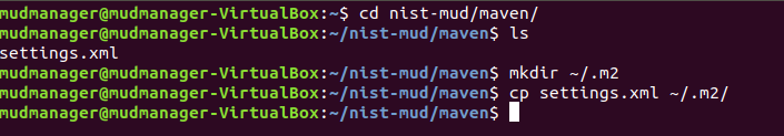
In the nist-mud directory, run the commands below:
cd

cd nist-mud/

mvn -e clean install -nsu -Dcheckstyle.skip -DskipTests -Dmaven.javadoc.skip=true

Open port 6653 on the controller stack for TCP access so the switches can connect by executing the command below:
sudo ufw allow 6653/tcp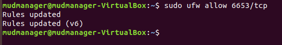
OpenDaylight uses port 8181 for the REST API. That port should be opened if access to the REST API is desired from outside the controller machine. Open port 8181 by executing the command below:
sudo ufw allow 8181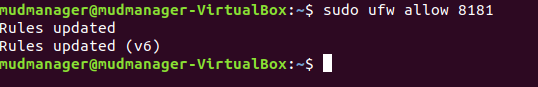
Change to the bin directory by executing the command below:
~/nist-mud/sdnmud-aggregator/karaf/target/assembly/binRun the command below:
./karaf clean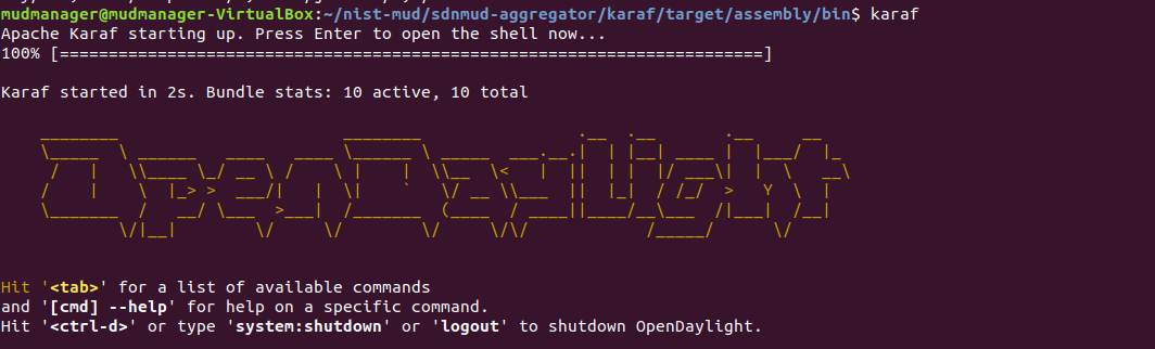
At the Karaf prompt, install MUD capabilities using:
feature:install features-sdnmud
Check if the feature is running by using the command
feature:list | grep sdnmudin Karaf.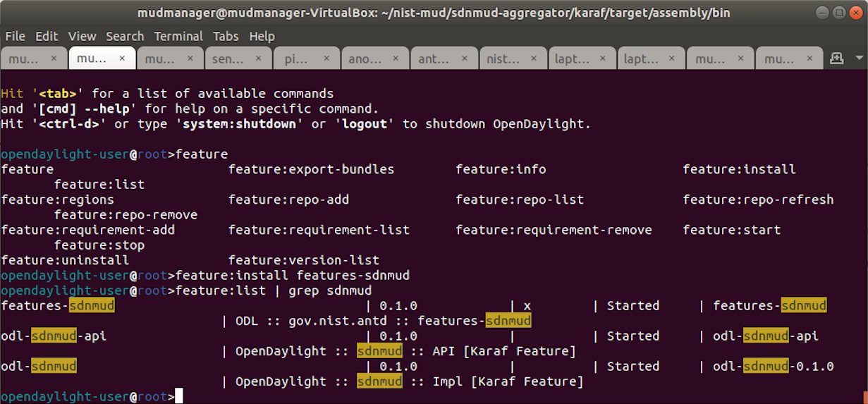
On the SDN controller/MUD manager host, run a script to configure the SDN controller and add bindings for the controller abstractions defined in the test MUD files. This script pushes configuration information for the MUD manager application (
sdnmud-config.json) as well as network configuration information for the managed local area network (LAN) (controllerclass-mapping.json). The latter file specifies bindings for the controller classes that are used in the MUD file as well as subnet information for classification of local addresses. These are scoped to a single policy enforcement point, which is identified by a switch-id. By default, the switch ID isopenflow:MAC-addresswhereMAC-addressis the MAC address of the switch interface that connects to the SDN controller (in decimal). This must be unique per switch. Note too, that we identify whether a switch is wireless.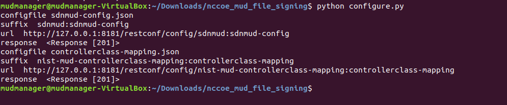
Example Python script (configure.py):
import requests
import json
import argparse
import os

if \__name__=="__main__":
    if os.environ.get("CONTROLLER_ADDR") is None:
        print "Please set environment variable CONTROLLER_ADDR to the address of the opendaylight controller"

    controller_addr = os.environ.get("CONTROLLER_ADDR")

    headers= {"Content-Type":"application/json"}
    for (configfile,suffix) in {
        ("sdnmud-config.json", "sdnmud:sdnmud-config"),
        ("controllerclass-mapping.json","nist-mud-controllerclass-mapping:controllerclass-mapping")
    }:
        data = json.load(open(configfile))
        print "configfile", configfile
        print "suffix ", suffix
        url = "http://" + controller_addr + ":8181/restconf/config/" + suffix
        print "url ", url
        r = requests.put(url, data=json.dumps(data), headers=headers , auth=('admin', 'admin'))
        print "response ", r
Example controller class mapping (controllerclass-mapping.json):
{
    "controllerclass-mapping" : {
        "switch-id" : "openflow:123917682138002",
        "controller" : [
            {
                "uri" : "urn:ietf:params:mud:dns",
                "address-list" : [ "10.0.41.1" ]
            },
            {
                "uri" : "urn:ietf:params:mud:dhcp",
                "address-list" : [ "10.0.41.1" ]
            },
            {
                "uri" : "*https://controller.nist.local*",
                "address-list" : [ "10.0.41.225" ]
            },
            {
                "uri" : "*https://sensor.nist.local/nistmud1*",
                "address-list" : [ "10.0.41.225" ]
           }
        ],
        "local-networks": [ "10.0.41.0/24" ],
        "wireless" : true
    }
}
Example SDN MUD configuration (sdnmud-config.json):
{
    "sdnmud-config" : {
        "ca-certs": "lib/security/cacerts",
        "key-pass" : "changeit",
        "trust-self-signed-cert" : true,
        "mfg-id-rule-cache-timeout": 120,
        "relaxed-acl" : false
    }
}
5.2 MUD File Server
5.2.1 MUD File Sever Overview
The MUD file server is responsible for serving the MUD file and the corresponding signature file upon request from the MUD manager. For testing purposes, the MUD file server is run on 127.0.0.1 on the same machine as the MUD manager. This allows us to examine the logs to check if the MUD file has been retrieved. For testing purposes, host name verification for the TLS connection to the MUD file server is disabled in the configuration of the MUD manager.
5.2.2 Configuration Overview
The following subsections document the software, hardware, and network configurations for the MUD file server.
5.2.2.1 Hardware Configuration
The MUD file server was hosted on the same machine as the SDN controller.
5.2.2.2 Network Configuration
The MUD file server was hosted on the same machine as the SDN controller. To direct the MUD manager to retrieve the MUD files from the MUD file server, the host
name of the two manufacturers that are present in the MUD URLs used for testing are both mapped to 127.0.0.1 in the /etc/hosts file of the Java Virtual
Machine in which the MUD manager is running. This static configuration is read by the MUD manager when it starts. The name resolution information in the
/etc/hosts file directs the MUD manager to retrieve the test MUD files from the MUD file server.
5.2.2.3 Software Configuration
In this build, serving MUD files requires Python 2.7 and the Python requests package. These may be installed using apt and pip. After creation of the MUD files by using mudmaker.org, the MUD files were signed, and the certificates used for signing were imported into the trust store of the Java Virtual Machine in which the MUD manager is running.
5.2.3 Setup
5.2.3.1 MUD File Creation
This build also leveraged the MUD Maker online tool found at www.mudmaker.org. For detailed instructions on creating a MUD file using this online tool, please refer to Build 1’s MUD File Creation section.
5.2.3.2 MUD File Signing
Sign and import the desired MUD files. An example script (
sign-and-import1.sh) can be found below.
The shell script that was used in this build is shown below. This script generates a signature based on the private key of a DigiCert-issued certificate and imports the certificate into the trust store of the Java Virtual Machine. This is done for both MUD files.
CACERT=DigiCertCA.crt
MANUFACTURER_CRT=nccoe_mud_file_signing.crt
MANUFACTURER_KEY=mudsign.key.pem
MANUFACTURER_ALIAS=sensor.nist.local
MANUFACTURER_SIGNATURE=mudfile-sensor.p7s
MUDFILE=mudfile-sensor.json
openssl cms -sign -signer $MANUFACTURER_CRT -inkey $MANUFACTURER_KEY -in $MUDFILE -binary -noattr -outform DER -certfile $CACERT -out $MANUFACTURER_SIGNATURE
openssl cms -verify -binary -in $MANUFACTURER_SIGNATURE -signer $MANUFACTURER_CRT -inform DER -content $MUDFILE
MANUFACTURER_ALIAS=otherman.nist.local
MUDFILE=mudfile-otherman.json
MANUFACTURER_SIGNATURE=mudfile-otherman.p7s
openssl cms -sign -signer $MANUFACTURER_CRT -inkey $MANUFACTURER_KEY -in $MUDFILE -binary -noattr -outform DER -certfile $CACERT -out $MANUFACTURER_SIGNATURE
openssl cms -verify -binary -in $MANUFACTURER_SIGNATURE -signer $MANUFACTURER_CRT -inform DER -content $MUDFILE
sudo -E $JAVA_HOME/bin/keytool -delete -alias digicert -keystore $JAVA_HOME/jre/lib/security/cacerts -storepass changeit
sudo -E $JAVA_HOME/bin/keytool -importcert -file $CACERT -alias digicert -keystore $JAVA_HOME/jre/lib/security/cacerts -storepass changeit
5.2.3.3 MUD File Serving
Run a script that serves desired MUD files and signatures. An example Python script (mudfile-server.py) can be found below.
Save a copy of the mudfile-server.py Python script onto the NIST SDN controller/MUD manager configured in Section 5.1:
import BaseHTTPServer, SimpleHTTPServer
import ssl
import urlparse

# Dummy manufacturer server for testing
class MyHTTPRequestHandler(SimpleHTTPServer.SimpleHTTPRequestHandler):

    def do_GET(self):
        print ("DoGET " + self.path)
        self.send_response(200)
        if self.path == "/nistmud1" :
            with open("mudfile-sensor.json", mode="r") as f:
                data = f.read()
            print("Read " + str(len(data)) + " chars ")
            self.send_header("Content-Length", len(data))
            self.end_headers()
            self.wfile.write(data)
        elif self.path == "/nistmud2" :
            with open("mudfile-otherman.json", mode="r") as f:
                data = f.read()
            print("Read " + str(len(data)) + " chars ")
            self.send_header("Content-Length", len(data))
            self.end_headers()
            self.wfile.write(data)
        elif self.path == "/nistmud1/mudfile-sensor.p7s":
            with open("mudfile-sensor.p7s",mode="r") as f:
                data = f.read()
            print("Read " + str(len(data)) + " chars ")
            self.send_header("Content-Length", len(data))
            self.end_headers()
            self.wfile.write(data)
        elif self.path == "/nistmud2/mudfile-otherman.p7s":
            with open("mudfile-otherman.p7s",mode="r") as f:
                data = f.read()
            print("Read " + str(len(data)) + " chars ")
            self.send_header("Content-Length", len(data))
            self.end_headers()
            self.wfile.write(data)
        else:
            print("UNKNOWN URL!!")
            self.wfile.write(b'Hello, world!')

httpd = BaseHTTPServer.HTTPServer(('0.0.0.0', 443), MyHTTPRequestHandler)
httpd.socket = ssl.wrap_socket (httpd.socket, keyfile='./mudsigner.key', certfile='./mudsigner.crt', server_side=True)
httpd.serve_forever()
From the same directory as the previous step, execute the command below to start the MUD file server:
sudo -E python mudfile-server.py
5.3 Northbound Networks Zodiac WX Access Point
5.3.1 Northbound Networks Zodiac WX Access Point Overview
The Zodiac WX, in addition to being a wireless access point, includes the following logical components: an SDN switch, a NAT router, a DHCP server, and a DNS server. The Zodiac WX is powered by OpenWRT and Open vSwitch. Open vSwitch directly integrates into the wireless configuration. The Zodiac WX works with any standard OpenFlow-compatible controllers and requires no modifications because it appears to the controller as a standard OpenFlow switch.
5.3.2 Configuration Overview
The following subsections document the network, software, and hardware configurations for the SDN-capable Northbound Networks Zodiac WX.
5.3.2.1 Network Configuration
The access point is configured to have a static public address on the public side of the NAT. For purposes of testing, we use 203.0.113.x addresses on the public network. The public side of the NAT is given the address of 203.0.113.1. The DHCP server is set up to allocate addresses to wireless devices on the LAN. The SDN controller/MUD manager is connected to the public side of the NAT. The Open vSwitch configuration for the access point is given the address of the SDN controller, which is shown in the setup below.
5.3.2.2 Software Configuration
At this implementation, no additional software configuration was required.
5.3.2.3 Hardware Configuration
At this implementation, no additional hardware configuration was required.
5.3.3 Setup
On the Zodiac WX, DNSmasq supports both DHCP and DNS. For testing purposes, it will be necessary to access several web servers (two update servers called www.nist.local and an unapproved server called www.antd.local). The following commands enable the Zodiac WX to resolve the web server host names to their IP addresses.
Set up the access point to resolve the addresses for the web server host names by opening the file
/etc/dnsmasq.confon the access point.Add the following line to the
dnsmasq.conffile:addn-hosts=/etc/hosts.nist.local
The file
/etc/hosts.nist.localhas the host name to address mapping. The mapping used for our tests is shown below (Note that the host www.nist.local maps to two addresses on the public side).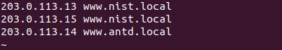
On the Zodiac WX configuration web page in the System->Startup tab, indicate where (IP address and port) the Open vSwitch Daemon connects to the controller.
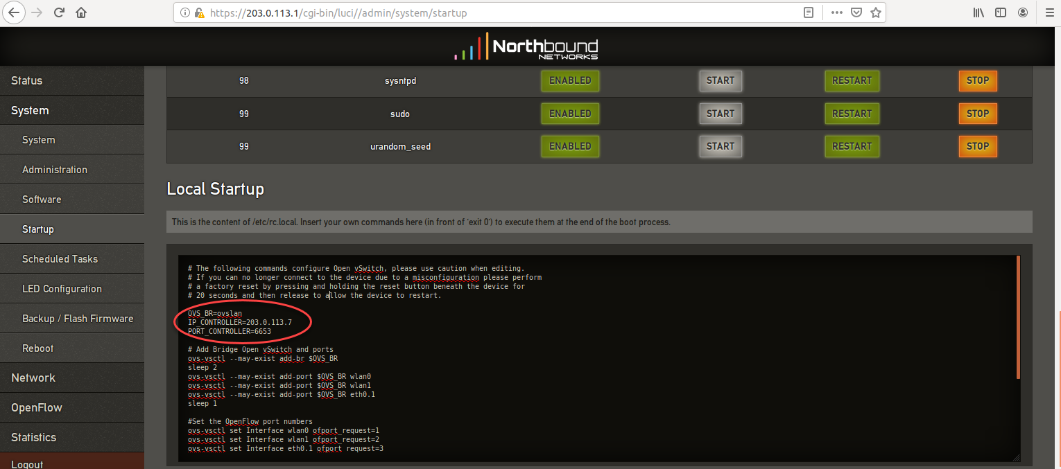
5.4 DigiCert Certificates
DigiCert’s CertCentral web-based platform allows provisioning and management of publicly trusted X.509 certificates for a variety of purposes. After establishing an account, clients can log in, request, renew, and revoke certificates by using only a browser. For Build 4, the Premium Certificate created in Build 1 was leveraged for signing the MUD files. To request and implement DigiCert certificates, follow the documentation in Build 1’s DigiCert Certificates section and subsequent sections.
5.5 IoT Devices
5.5.1 IoT Devices Overview
This section provides configuration details for the Linux-based Raspberry Pis used in the build, which emit MUD URLs by using DHCP.
5.5.2 Configuration Overview
The devices used in this build were multiple Raspberry Pi development kits that were configured to act as IoT devices. The devices run Raspbian 9, a Linux-based operating system, and are configured to emit a MUD URL during a typical DHCP transaction. These devices were used to test interactions related to MUD capabilities.
5.5.2.1 Network Configuration
The kits are connected to the network over a wireless connection. Their IP addresses are assigned dynamically by the DHCP server on the Zodiac WX access point.
5.5.2.2 Software Configuration
The Raspberry Pis are configured on Raspbian. They also utilized dhclient as their default DHCP clients to manually initiate a DHCP interaction. This DHCP
client is provided with many Linux distributions and can be installed using a preferred package manager if not currently present. Dhclient uses a configuration
file: /etc/dhclient.conf. This needs to be modified to include the MUD URL that the device will emit in its DHCP requests. (The modification details are
provided in the setup information below.)
5.5.2.3 Hardware Configuration
Multiple Raspberry Pi 3 Model B devices were used.
5.5.3 Setup
Each Raspberry Pi used in this build was intended to represent a different class of device (manufacturer, other manufacturer, local networks, controller classes). The type of device was determined by the MUD URL being emitted by the device. If no MUD URL is emitted, the device is an unclassified local network device.
On each Pi, changes were made to
/etc/network/interfacesto add a line that allows the Pi to authenticate to the access point. The following line is added to the network interface as shown below:wpa-conf /etc/wpa_supplicant/wpa_supplicant.conf.northbound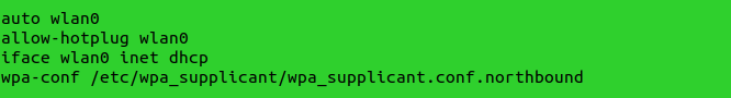
The file (
/etc/wpa_supplicant/wpa_supplicant.conf.northbound) is shown below: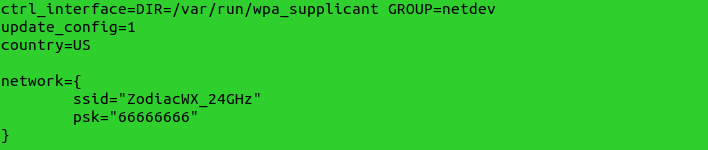
A dhclient configuration file can be altered (by adding information) to allow for emission of a MUD URL in the DHCP transaction. Modify the
dhclient.conffile with the command:vi /etc/dhcp/dhclient.confA send MUD URL line must be added as well as a
mud-urlin the request line. In this build, multiple MUD URLs were transmitted, depending on the type of the device. Example alterations made to dhclient configuration files can be seen below:send mud-url = "https://sensor.nist.local/nistmud1"; send mud-url = "https://otherman.nist.local/nistmud2";
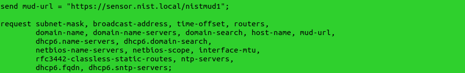
To control the time at which the MUD URL is emitted, we manually reacquire the DHCP address rather than have the device acquire the MUD URL on boot. Emit the MUD URL and attain an IP address by sending the altered dhclient configuration file manually with the following commands:
sudo rm /var/lib/dhcp/dhclient.leases

sudo ifconfig wlan0 0.0.0.0

sudo dhclient -v wlan0 -cf /etc/dhcp/dhclient.conf.toaster
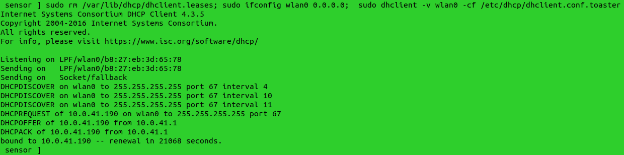
5.6 Update Server
5.6.1 Update Server Overview
This section provides configuration details for the Linux-based IoT development kit used in the build, which acts as an update server. This update server will attempt to access and be accessed by the IoT device, which, in this case, is one of the development kits built in the lab. The update server is a web server that hosts mock software update files to be served as software updates to our IoT device devkits. When the server receives an http request, it sends the corresponding update file.
5.6.2 Configuration Overview
The devkit runs Raspbian 9, a Linux-based operating system, and is configured to act as an update server. This host was used to test approved internet interactions related to MUD capabilities.
5.6.2.1 Network Configuration
The web server host has a static public IP address configuration and is connected to the access point on the wired interface. It is given an address on the 203.0.113 network.
5.6.2.2 Software Configuration
The Raspberry Pi is configured on Raspbian. The devkit also utilized a simple Python script to run an http server to test MUD capabilities.
5.6.2.3 Hardware Configuration
The hardware used for this devkit includes a Raspberry Pi 3 Model B.
5.6.3 Setup
The primary configuration needed for the web server device is done with the DNS mapping on the Zodiac WX access point to be discussed in the section related to setup of the Northbound Networks Zodiac WX Access Point The Raspberry Pi is required to run a simple http server.
Copy the example Python script below onto the Raspberry Pi:
Example Python script (
httpserver.py):import SimpleHTTPServer import SocketServer import argparse if __name__ == "__main__": parser = argparse.ArgumentParser() parser.add_argument("-H", help="Host address", default="0.0.0.0") parser.add_argument("-P", help="Port ", default="80") args = parser.parse_args() hostAddr = args.H PORT = int(args.P) Handler = SimpleHTTPServer.SimpleHTTPRequestHandler httpd = SocketServer.TCPServer((hostAddr, PORT), Handler) print "serving at port", PORT httpd.serve_forever()
From the same directory as the script copied in the previous step, execute the command below to start the http server:
sudo python httpserver.py -P 443
5.7 Unapproved Server
5.7.1 Unapproved Server Overview
This section provides configuration details for the Linux-based IoT development kit used in the build, which acts as an unapproved internet host. This host will attempt to access and to be accessed by an IoT device, which, in this case, is one of the MUD-capable devices on the network.
The unapproved server is an internet host that is not explicitly authorized in the MUD file to communicate with the IoT device. When the IoT device attempts to connect to this server, the switch should not allow this traffic because it is not an approved internet service per the corresponding MUD file. Likewise, when the server attempts to connect to the IoT device, this traffic should be denied at the switch.
5.7.2 Configuration Overview
The devkit runs Raspbian 9, a Linux-based operating system, and is configured to act as an unapproved internet host. This host was used to test unapproved internet interactions related to MUD capabilities.
5.7.2.1 Network Configuration
The web host has a static public IP address configuration and is connected to the access point on the wired interface. It is given an address on the 203.0.113 network.
5.7.2.2 Software Configuration
The Raspberry Pi is configured on Raspbian. The devkit also utilized a simple Python script to run an http server to test MUD capabilities.
5.7.2.3 Hardware Configuration
The hardware used for this devkit includes a Raspberry Pi 3 Model B.
5.7.3 Setup
The primary configuration needed for the web server device is accomplished by the DNS mapping on the Zodiac WX access point to be discussed in the section related to setup of the Northbound Networks Zodiac WX Access Point. The Raspberry Pi is required to run a simple http server.
Copy the example Python script below onto the Raspberry Pi:
Example Python script (
httpserver.py):import SimpleHTTPServer import SocketServer import argparse if __name__ == "__main__": parser = argparse.ArgumentParser() parser.add_argument("-H", help="Host address", default="0.0.0.0") parser.add_argument("-P", help="Port ", default="80") args = parser.parse_args() hostAddr = args.H PORT = int(args.P) Handler = SimpleHTTPServer.SimpleHTTPRequestHandler httpd = SocketServer.TCPServer((hostAddr, PORT), Handler) print "serving at port", PORT httpd.serve_forever()
From the same directory as the script copied in the previous step, execute the command below to start the http server:
sudo python httpserver.py -P 443